Embed Size (px)
Citation preview
Installation, Operation andMaintenance Manual
VLT® 6000 SeriesAdjustable Frequency Drive
12/01 23-6108-00Revision K
2 VLT is a registered Danfoss trademark
Rotating shafts and electrical equipment canbe hazardous. Therefore, it is stronglyrecommended that all electrical work conformto National Electrical Code (NEC) and all localregulations. Installation, start-up andmaintenance should be performed only byqualified personnel.
Factory recommended procedures, included in this manual, should befollowed. Always disconnect electrical power before working on theunit.
Although shaft couplings or belt drives are generally not furnished bythe manufacturer, rotating shafts, couplings and belts must be protectedwith securely mounted metal guards that are of sufficient thickness toprovide protection against flying particles such as keys, bolts andcoupling parts. Even when the motor is stopped, it should be consid-ered “alive” as long as its controller is energized. Automatic circuits maystart the motor at any time. Keep hands away from the output shaft untilthe motor has completely stopped and power is disconnected from thecontroller.
Motor control equipment and electronic controls are connected tohazardous line voltages. When servicing drives and electronic controls,there will be exposed components at or above line potential. Extremecare should be taken to protect against shock. Stand on an insulatingpad and make it a habit to use only one hand when checking compo-nents. Always work with another person in case of an emergency.Disconnect power whenever possible to check controls or to performmaintenance. Be sure equipment is properly grounded. Wear safetyglasses whenever working on electric control or rotating equipment.
Safety Guidelines1. The drive must be disconnected from the AC line before any
service work is done.2. The “Stop/Off” key on the local control panel of the drive does not
disconnect the equipment from the AC line and is not to be used asa safety switch.
3. Correct protective grounding of the equipment must be estab-lished. The user must be protected against supply voltage and themotor must be protected against overload in accordance withapplicable national and local regulations.
4. Ground currents are higher than 3 mA.
Warnings Against Unintended Start1. While the drive is connected to the AC line, the motor can be
brought to a stop by means of external switch closures, serial buscommands or references. If personal safety considerations make itnecessary to ensure that no unintended start occurs, these stopsare not sufficient.
2. During programming of parameters, the motor may start. Becertain that no one is in the area of the motor or driven equipmentwhen changing parameters.
3. A motor that has been stopped may start unexpectedly if faultsoccur in the electronics of the drive, or if an overload, a fault in thesupply AC line or a fault in the motor connection or other faultclears.
4. If the “Local/Hand” key is activated, the motor can only be broughtto a stop by means of the “Stop/Off” key or an external safetyinterlock.
Motor Overload Protection
NOTEIt is responsibility of user or person installingdrive to provide proper grounding and branchcircuit protection for incoming power andmotor overload according to National ElectricalCode (NEC) and local codes.
The electronic thermal relay (ETR) in UL listed VLTs provides Class 20motor overload protection in accordance with the NEC in single motorapplications when parameter 117 is set for ETR TRIP and parameter105 is set for rated motor current.
Touching electrical parts may be fatal – even after equipment has
been disconnected from AC line. To be sure that capacitors have
fully discharged, wait 14 minutes after power has been removed
before touching any internal component.
Copyright © 2001, Danfoss Graham
3VLT is a registered Danfoss trademark
Table of Contents
General ................................................................................................................................................................................................................... 5Clearances......................................................................................................................................................................................................... 5Plenum Mounting ................................................................................................................................................................................................ 5Grounding Plate ................................................................................................................................................................................................. 5Shielded Wires ................................................................................................................................................................................................... 5UL, C-UL, and CE Conformity ............................................................................................................................................................................ 5
Cross Reference — Model Number to VLT Type ..................................................................................................................................................... 6Input Fuses ............................................................................................................................................................................................................. 7Internal Drive Fuses ................................................................................................................................................................................................ 7Locations of Conduit Entry, Terminal Blocks and Switches ......................................................................................................................................... 8Location of Input Power (Mains) and Output Power (Motor Terminal Blocks) ........................................................................................................... 11Power Connections ............................................................................................................................................................................................... 14
Input Power Connection ................................................................................................................................................................................... 14Motor Wiring Connection ................................................................................................................................................................................... 14Grounding ........................................................................................................................................................................................................ 14Electronic Thermal Protection ............................................................................................................................................................................ 14Terminal Tightening Torque .............................................................................................................................................................................. 15Terminal Tightening Torque (continued) ............................................................................................................................................................ 16Terminal Tightening Torque (continued) ............................................................................................................................................................ 17External DC Bus Connection ............................................................................................................................................................................ 18Multiple Motors ................................................................................................................................................................................................. 18High Voltage Form C Relay .............................................................................................................................................................................. 18
Control Connections .............................................................................................................................................................................................. 19Electrical Installation, Control Terminals ............................................................................................................................................................. 19Typical Control Connections ............................................................................................................................................................................. 20Electrical Installation, Control Wiring .................................................................................................................................................................. 21DIP Switches 1 through 4 ................................................................................................................................................................................. 21Ground Leakage Current ................................................................................................................................................................................. 21Galvanic Isolation ............................................................................................................................................................................................. 22Extra Safety Protection ...................................................................................................................................................................................... 22Electrical Noise ................................................................................................................................................................................................. 22
Application Control Connection Examples .............................................................................................................................................................. 23Control Panel ........................................................................................................................................................................................................ 24
Keys for Parameter Changes ........................................................................................................................................................................... 24Indicator Lamps ................................................................................................................................................................................................ 25Local Control .................................................................................................................................................................................................... 25Display Modes ................................................................................................................................................................................................. 25Changing Data ................................................................................................................................................................................................. 27Changing Numeric Values ................................................................................................................................................................................ 27Changing Functional Values ............................................................................................................................................................................. 27Changing Numeric Values in a List .................................................................................................................................................................... 27
Quick Menu ........................................................................................................................................................................................................... 28To Enter or Change Quick Menu Parameter Data ............................................................................................................................................. 28Example of Changing Parameter Data .............................................................................................................................................................. 28Extended Menu ................................................................................................................................................................................................ 29Manual Initialization of Parameters ..................................................................................................................................................................... 29Uploading Parameters ...................................................................................................................................................................................... 29
VLT 6000 Start-Up ................................................................................................................................................................................................ 30Pre-installation Checks ...................................................................................................................................................................................... 30Installation Checks ............................................................................................................................................................................................ 30Setting Up Drive for Motor Start ......................................................................................................................................................................... 30Operational Tests — HAND .............................................................................................................................................................................. 30Operational Tests — AUTO .............................................................................................................................................................................. 30Final Adjustments .............................................................................................................................................................................................. 30
4 VLT is a registered Danfoss trademark
Programming......................................................................................................................................................................................................... 31Description of Parameters ................................................................................................................................................................................. 31Setup Configuration and Parameters Copy ....................................................................................................................................................... 31
Operation and DisplayParameters 000 through 017 ............................................................................................................................................................................ 31Setup of User-defined Readout ......................................................................................................................................................................... 32
Load and MotorParameters 100 through 117 ............................................................................................................................................................................ 36Procedure for Automatic Motor Adaptation: ........................................................................................................................................................ 38DC Braking ...................................................................................................................................................................................................... 40Motor Thermal Protection .................................................................................................................................................................................. 41References and LimitsParameters 200 through 228 ............................................................................................................................................................................ 42Reference Handling .......................................................................................................................................................................................... 43Reference Type ............................................................................................................................................................................................... 46Warning Functions ............................................................................................................................................................................................ 48
Inputs and OutputsParameters 300 through 328 ............................................................................................................................................................................ 50Analog Inputs ................................................................................................................................................................................................... 53Analog/Digital Outputs ....................................................................................................................................................................................... 56Relay Outputs ................................................................................................................................................................................................... 59
Application FunctionsParameters 400 through 427 ........................................................................................................................................................................... 61Sleep Mode ...................................................................................................................................................................................................... 61Feedback Signals in Open Loop ....................................................................................................................................................................... 65
PID for Process Regulation .................................................................................................................................................................................... 66Feedback ......................................................................................................................................................................................................... 66Reference (Setpoint) ......................................................................................................................................................................................... 66Inverse Regulation ........................................................................................................................................................................................... 66Anti-windup ...................................................................................................................................................................................................... 66Start-up Conditions ........................................................................................................................................................................................... 66Differentiator Gain Limit ...................................................................................................................................................................................... 67Lowpass Filter .................................................................................................................................................................................................. 67Optimization of the Process Regulator ................................................................................................................................................................ 67
PID Overview ....................................................................................................................................................................................................... 67Feedback Handling .......................................................................................................................................................................................... 67
Serial Communication for FC Protocol .................................................................................................................................................................... 72Protocols .......................................................................................................................................................................................................... 72Packet Communication ...................................................................................................................................................................................... 72
Serial CommunicationParameters 500 through 566 ............................................................................................................................................................................ 82Warning Words, Extended Status Word and Alarm Word ................................................................................................................................... 88
Service FunctionsParameters 600 through 631 ............................................................................................................................................................................ 90
Relay Card FunctionsParameters 700 through 711 ............................................................................................................................................................................ 95Electrical Installation of the Relay Card .............................................................................................................................................................. 95
Status Messages ................................................................................................................................................................................................... 96Warnings and Alarms ........................................................................................................................................................................................ 98Warnings .......................................................................................................................................................................................................... 99Alarms .............................................................................................................................................................................................................. 99
Factory Settings ................................................................................................................................................................................................... 104
SOFTWARE VERSION NOTICE: These Operating Instructions are used for all VLT 6000Series Drives with software version 2.X and all prior versions. The software version numbercan be determined from parameter 624, Software Version.
5VLT is a registered Danfoss trademark
GeneralThe specific installation instructions may vary depending upon themodel of VLT 6000 Series being installed. When this occurs, the modelcan be identified by a “VLT Type 6XXX” number. This number can befound on the red nameplate on the outside left side of the driveenclosure, or the outside right side of a drive with an auxiliaryenclosure. A cross reference from the VLT Type to the model numbercan be found on the next page.
The drive must always be installed vertically. To ensure that no injuryor damage occurs, the drive must always be firmly attached to the wallor the floor before further installation work is carried out.
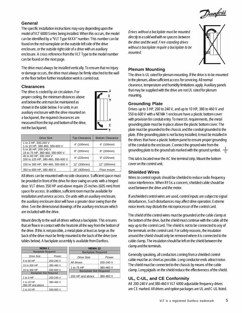
ClearancesThe drive is cooled by air circulation. Forproper cooling, the minimum distances aboveand below the unit must be maintained asshown in the table below. For units in anauxiliary enclosure with the drive mounted ona backpanel, the required clearances aremeasured from the top and bottom of the drive,not the backpanel.
All drives can be mounted with no side clearance. Sufficient space mustbe provided in front of the drive for door swing on units with a hingeddoor. VLT drives 350 HP and above require 25 inches (605 mm) frontspace for access. In addition, sufficient room must be available forinstallation and service access. On units with an auxiliary enclosure,the auxiliary enclosure door will have a greater door swing than thedrive. See the dimensional drawings of the auxiliary enclosure whichare included with the drive.
Mount directly to the wall all drives without a backplate. This ensuresthat air flow is in contact with the heatsink all the way from the bottom ofthe drive. If this is not possible, a metal plate at least as large as theback of the drive must be firmly mounted to the back of the drive (seetables below). A backplate assembly is available from Danfoss.
Drives without a backplate must be mounteddirectly to a solid wall with no spacers betweenthe drive and the wall. Free-standing driveswithout a backplate require a backplate to bemounted.
Plenum MountingThe drive is UL rated for plenum mounting. If the drive is to be mountedin the plenum, allow sufficient access for servicing. All normalclearance, temperature and humidity limitations apply. Auxiliary panelsthat may be supplied with the drive are not UL rated for plenummounting.
Grounding PlateDrives up to 3 HP, 200 to 240 V, and up to 10 HP, 380 to 460 V and550 to 600 V with a NEMA 1 enclosure have a plastic bottom coverwith provision for conduit entry. To meet UL requirements, the metalgrounding plate must be in place above the plastic bottom cover. Theplate must be grounded to the chassis and the conduit grounded to theplate. If the grounding plate is not factory installed, it must be installed inthe drives that have a plastic bottom panel to ensure proper groundingof the conduit to the enclosure. Connect the ground wire from thegrounding plate to the ground tab marked with the ground symbol.
This tab is located near the AC line terminal strip. Mount the bottomcover on the control unit.
Shielded WiresWires to control signals should be shielded to reduce radio frequencynoise interference. When RFI is a concern, shielded cable should beused between the drive and the motor.
If unshielded control wires are used, control inputs are subject to signaldisturbances. Such disturbances may affect drive operation. Extremenoise levels may disturb the microprocessor of the control card.
The shield of the control wires must be grounded at the cable clamp atthe bottom of the drive, but the shield must continue with the cable all theway up to the control card. The shield is not to be connected to any ofthe terminals on the control card. For safety reasons, the insulationaround the shield should only be removed where it is connected to thecable clamp. The insulation should be left on the shield between theclamp and the terminals.
Generally speaking, all conductors coming from a shielded controlcable must be as short as possible. Long conductor ends attract noise.The shield must be connected to the chassis by means of the cableclamp. Long pigtails on the shield reduce the effectiveness of the shield.
UL, C-UL, and CE ConformityAll 200-240 V and 380-460 V VLT 6000 adjustable frequency drivesare CE marked. All drives and option packages are UL and C-UL listed.
NEMA 1 Backplate Required
Drive Size Power
5 to 60 HP 200-240 V
15 to 300 HP 380-460 V
15 to 300 HP 550-600 V Backplate Not Required
1 to 3 HP 200-240 V
1 to 10 HP 350 HP and above
380-460 V
1 to 10 HP 550-600 V
X
X
Drive Size Top Clearance Bottom Clearance
1 to 3 HP, 200-240 V 1 to 10 HP, 380-460, 550-600 V 4" (100mm) 4" (100mm)
5 to 30 HP, 200-240 V 15 to 75 HP, 380-460, 550-600 V 8" (200mm) 8" (200mm)
40 to 60 HP, 200-240 V 100 to 125 HP, 380-460, 550-600 V 9" (225mm) 9" (225mm)
150 to 300 HP, 380-460, 550-600 V 12" (300mm) 12" (300mm)
350 to 600 HP, 380-460 V 16" (400mm) Floor mount
NEMA 12 Backplate Required
Drive Size Power
All drives 200-240 V
1 to 75 HP 380-460 V Backplate Not Required
100 HP and above 380-460 V
6 VLT is a registered Danfoss trademark
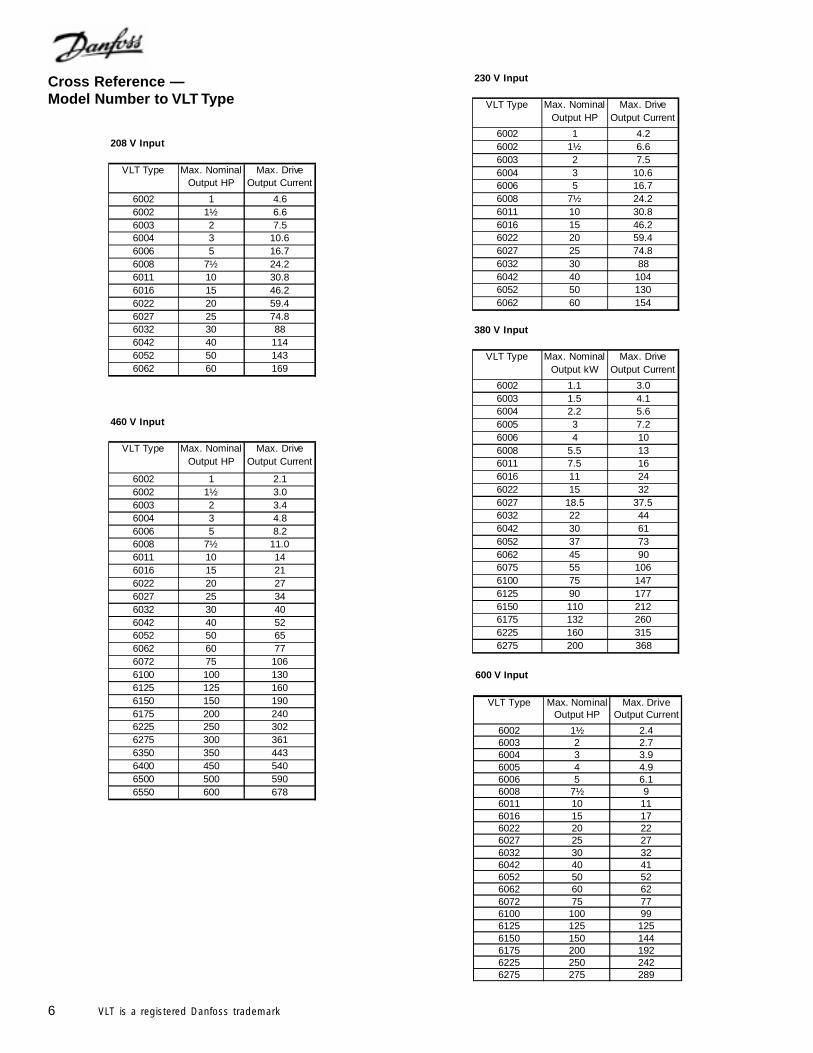
Cross Reference —Model Number to VLT Type
230 V Input
VLT Type Max. Nominal Output HP
Max. Drive Output Current
6002 1 4.26002 1½ 6.66003 2 7.56004 3 10.66006 5 16.76008 7½ 24.26011 10 30.86016 15 46.26022 20 59.46027 25 74.86032 30 886042 40 1046052 50 1306062 60 154
380 V Input
VLT Type Max. Nominal Output kW
Max. Drive Output Current
6002 1.1 3.06003 1.5 4.16004 2.2 5.66005 3 7.26006 4 106008 5.5 136011 7.5 166016 11 246022 15 326027 18.5 37.56032 22 446042 30 616052 37 736062 45 906075 55 1066100 75 1476125 90 1776150 110 2126175 132 2606225 160 3156275 200 368
208 V Input
VLT Type Max. Nominal Output HP
Max. Drive Output Current
6002 1 4.66002 1½ 6.66003 2 7.56004 3 10.66006 5 16.76008 7½ 24.26011 10 30.86016 15 46.26022 20 59.46027 25 74.86032 30 886042 40 1146052 50 1436062 60 169
460 V Input
VLT Type Max. Nominal Output HP
Max. Drive Output Current
6002 1 2.16002 1½ 3.06003 2 3.46004 3 4.86006 5 8.26008 7½ 11.06011 10 146016 15 216022 20 276027 25 346032 30 406042 40 526052 50 656062 60 776072 75 1066100 100 1306125 125 1606150 150 1906175 200 2406225 250 3026275 300 3616350 350 4436400 450 5406500 500 5906550 600 678
600 V Input
VLT Type Max. Nominal Output HP
Max. Drive Output Current
6002 1½ 2.46003 2 2.76004 3 3.96005 4 4.96006 5 6.16008 7½ 96011 10 116016 15 176022 20 226027 25 276032 30 326042 40 416052 50 526062 60 626072 75 776100 100 996125 125 1256150 150 1446175 200 1926225 250 2426275 275 289
7VLT is a registered Danfoss trademark
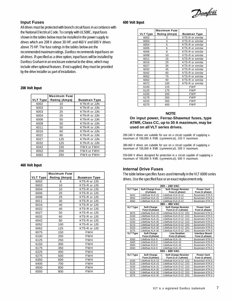
Input FusesAll drives must be protected with branch circuit fuses in accordance withthe National Electrical Code. To comply with UL508C, input fusesshown in the tables below must be installed in the power supply todrives which are 208 V above 30 HP, and 460 V and 600 V drivesabove 75 HP. The fuse ratings in the tables below are therecommended maximum ratings. Danfoss recommends input fuses onall drives. If specified as a drive option, input fuses will be installed byDanfoss Graham in an enclosure external to the drive, which mayinclude other optional features. If not supplied, they must be providedby the drive installer as part of installation.
460 Volt Input
208 Volt Input
600 Volt Input
NOTEOn input power, Ferraz-Shawmut fuses, typeATMR, Class CC, up to 30 A maximum, may beused on all VLT series drives.
Internal Drive FusesThe table below specifies fuses used internally in the VLT 6000 seriesdrives. Use the specified fuse or an exact replacement only.
200-240 V drives are suitable for use on a circuit capable of supplying amaximum of 100,000 A RMS (symmetrical), 250 V maximum.
380-460 V drives are suitable for use on a circuit capable of supplying amaximum of 100,000 A RMS (symmetrical), 500 V maximum.
550-600 V drives designed for protection in a circuit capable of supplying amaximum of 100,000 A RMS (symmetrical), 600 V maximum.
VLT TypeMaximum Fuse Rating (Amps) Bussman Type
6002 10 KTN-R or JJN6003 15 KTN-R or JJN6003 20 KTN-R or JJN6004 25 KTN-R or JJN6006 50 KTN-R or JJN6008 50 KTN-R or JJN6011 50 KTN-R or JJN6016 60 KTN-R or JJN6022 80 KTN-R or JJN6027 125 KTN-R or JJN6032 125 KTN-R or JJN6042 150 FWX or FWH6052 200 FWX or FWH6062 250 FWX or FWH
VLT TypeMaximum Fuse Rating (Amps) Bussman Type
6002 6 KTS-R or JJS6003 10 KTS-R or JJS6004 10 KTS-R or JJS6006 20 KTS-R or JJS6008 25 KTS-R or JJS6011 30 KTS-R or JJS6016 40 KTS-R or JJS6022 40 KTS-R or JJS6027 50 KTS-R or JJS6032 60 KTS-R or JJS6042 80 KTS-R or JJS6052 100 KTS-R or JJS6062 125 KTS-R or JJS6075 150 FWH6100 200 FWH6125 250 FWH6150 300 FWH6175 350 FWH6225 400 FWH6275 500 FWH6350 600 FWH6400 700 FWH6500 800 FWH6550 800 FWH
VLT TypeMaximum Fuse Rating (Amps) Bussman Type
6002 3 KTS-R or similar6003 4 KTS-R or similar6004 5 KTS-R or similar6005 6 KTS-R or similar6006 8 KTS-R or similar6008 10 KTS-R or similar6011 15 KTS-R or similar6016 20 KTS-R or similar6027 35 KTS-R or similar6032 45 KTS-R or similar6042 60 KTS-R or similar6052 75 KTS-R or similar6062 90 KTS-R or similar6072 100 KTS-R or similar6100 125 FWP6125 175 FWP6150 200 FWP6175 250 FWP6225 350 FWP6275 400 FWP
200 – 240 VAC VLT Type Soft Charge Fuse
(3 phase) Soft Charge Resistor
Fuse (1 phase) Power Card
Fuse (1 phase) 6042 Littelfuse KLK-15 Littelfuse KLK-D-12 Bussmann KTK-5 6052 Littelfuse KLK-15 Littelfuse KLK-D-12 Bussmann KTK-5 6062 Littelfuse KLK-15 Littelfuse KLK-D-12 Bussmann KTK-5
380 – 460 VAC VLT Type Soft Charge
Fuse (3 phase) Soft Charge Resistor Fuse (1 or 2 phase)
Power Card Fuse (1 phase)
6075 Littelfuse KLK-15 Littelfuse KLK-D-12 (2X) Bussmann KTK-5 6100 Littelfuse KLK-15 Littelfuse KLK-D-12 (1X) Bussmann KTK-5 6125 Littelfuse KLK-15 Littelfuse KLK-D-12 (1X) Bussmann KTK-5 6150 Littelfuse KLK-30 Littelfuse KLK-D-12 (1X) Bussmann KTK-5 6175 Littelfuse KLK-30 Littelfuse KLK-D-12 (2X) Bussmann KTK-5 6225 Littelfuse KLK-30 Littelfuse KLK-D-12 (2X) Bussmann KTK-5 6275 Littelfuse KLK-30 Littelfuse KLK-D-12 (2X) Bussmann KTK-5
VLT Type Soft Charge Fuse (3 phase)
Line Snubber Fuse (3 phase)
Interface Board Fuse (1 phase)
6350 Littelfuse KLK-9 Littelfuse KLK-15 Bussmann KTK-5 6400 Littelfuse KLK-9 Littelfuse KLK-15 Bussmann KTK-5 6500 Littelfuse KLK-9 Littelfuse KLK-15 Bussmann KTK-5 6550 Littelfuse KLK-9 Littelfuse KLK-15 Bussmann KTK-5
550 – 600 VAC
VLT Type Soft Charge Fuse (3 phase)
Soft Charge Resistor Fuse (1 or 2 phase)
Power Card Fuse (1 phase)
6100 Littelfuse KLK-15 Littelfuse KLK-D-12 (1X) Bussmann KTK-5 6125 Littelfuse KLK-15 Littelfuse KLK-D-12 (1X) Bussmann KTK-5 6150 Littelfuse KLK-15 Littelfuse KLK-D-12 (1X) Bussmann KTK-5 6175 Littelfuse KLK-30 Littelfuse KLK-D-12 (2X) Bussmann KTK-5 6225 Littelfuse KLK-30 Littelfuse KLK-D-12 (2X) Bussmann KTK-5 6275 Littelfuse KLK-30 Littelfuse KLK-D-12 (2X) Bussmann KTK-5
8 VLT is a registered Danfoss trademark
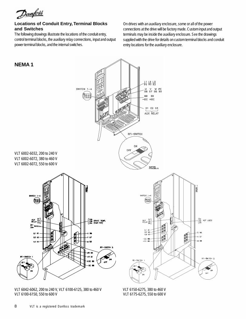
Locations of Conduit Entry, Terminal Blocksand Switches
NEMA 1
VLT 6002-6032, 200 to 240 VVLT 6002-6072, 380 to 460 V
VLT 6042-6062, 200 to 240 V, VLT 6100-6125, 380 to 460 V VLT 6150-6275, 380 to 460 V
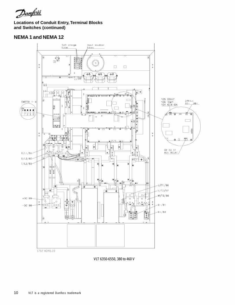
The following drawings illustrate the locations of the conduit entry,control terminal blocks, the auxiliary relay connections, input and outputpower terminal blocks, and the internal switches.
On drives with an auxiliary enclosure, some or all of the powerconnections at the drive will be factory made. Custom input and outputterminals may be inside the auxiliary enclosure. See the drawingssupplied with the drive for details on custom terminal blocks and conduitentry locations for the auxiliary enclosure.
VLT 6002-6072, 550 to 600 V
VLT 6100-6150, 550 to 600 V VLT 6175-6275, 550 to 600 V
9VLT is a registered Danfoss trademark
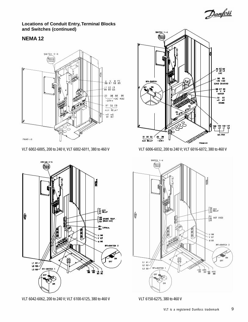
VLT 6002-6005, 200 to 240 V, VLT 6002-6011, 380 to 460 V VLT 6006-6032, 200 to 240 V; VLT 6016-6072, 380 to 460 V
VLT 6042-6062, 200 to 240 V; VLT 6100-6125, 380 to 460 V VLT 6150-6275, 380 to 460 V
Locations of Conduit Entry, Terminal Blocksand Switches (continued)
NEMA 12
10 VLT is a registered Danfoss trademark
NEMA 1 and NEMA 12
VLT 6350-6550, 380 to 460 V
Locations of Conduit Entry, Terminal Blocksand Switches (continued)
11VLT is a registered Danfoss trademark
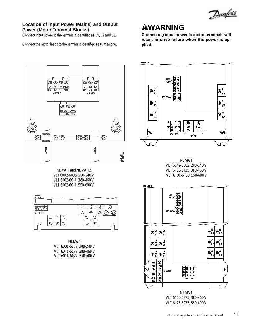
Location of Input Power (Mains) and OutputPower (Motor Terminal Blocks)Connect input power to the terminals identified as L1, L2 and L3.
Connect the motor leads to the terminals identified as U, V and W.
Connecting input power to motor terminals willresult in drive failure when the power is ap-plied.
NEMA 1VLT 6006-6032, 200-240 VVLT 6016-6072, 380-460 V
NEMA 1 and NEMA 12VLT 6002-6005, 200-240 VVLT 6002-6011, 380-460 V
NEMA 1VLT 6042-6062, 200-240 VVLT 6100-6125, 380-460 V
NEMA 1VLT 6150-6275, 380-460 VVLT 6175-6275, 550-600 V
VLT 6100-6150, 550-600 V
VLT 6016-6072, 550-600 V
VLT 6002-6011, 550-600 V
12 VLT is a registered Danfoss trademark
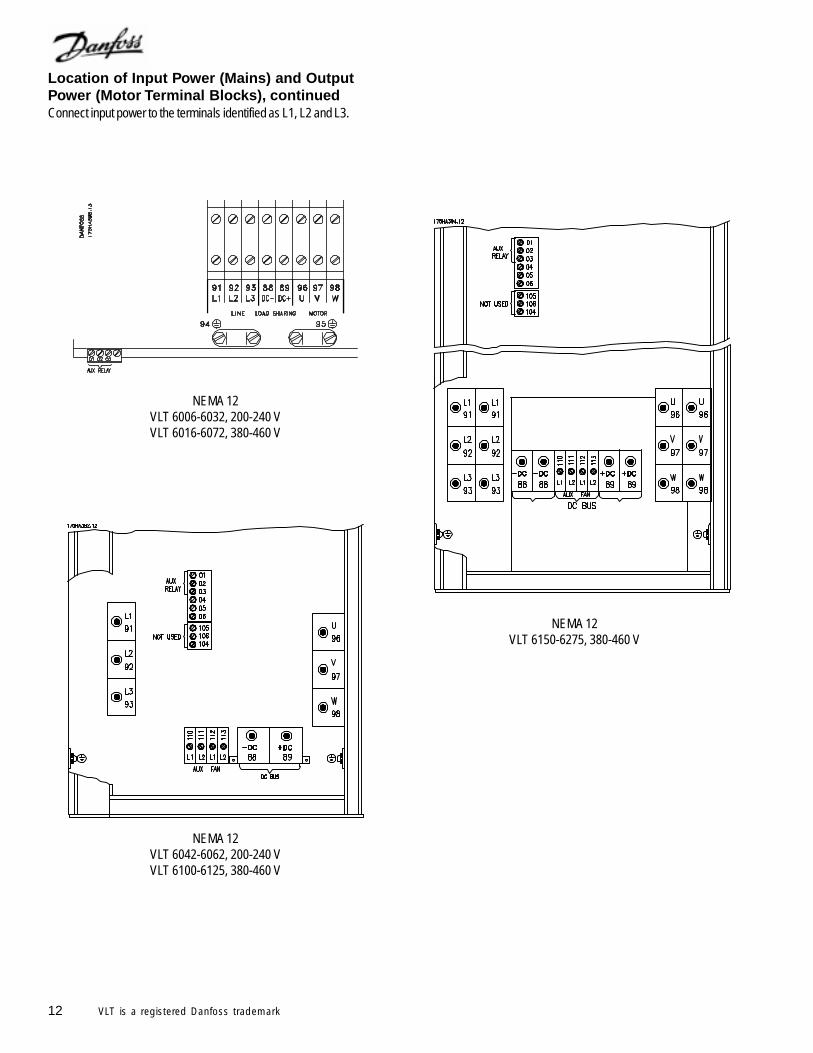
NEMA 12VLT 6006-6032, 200-240 VVLT 6016-6072, 380-460 V
NEMA 12VLT 6042-6062, 200-240 VVLT 6100-6125, 380-460 V
NEMA 12VLT 6150-6275, 380-460 V
Location of Input Power (Mains) and OutputPower (Motor Terminal Blocks), continuedConnect input power to the terminals identified as L1, L2 and L3.
13VLT is a registered Danfoss trademark
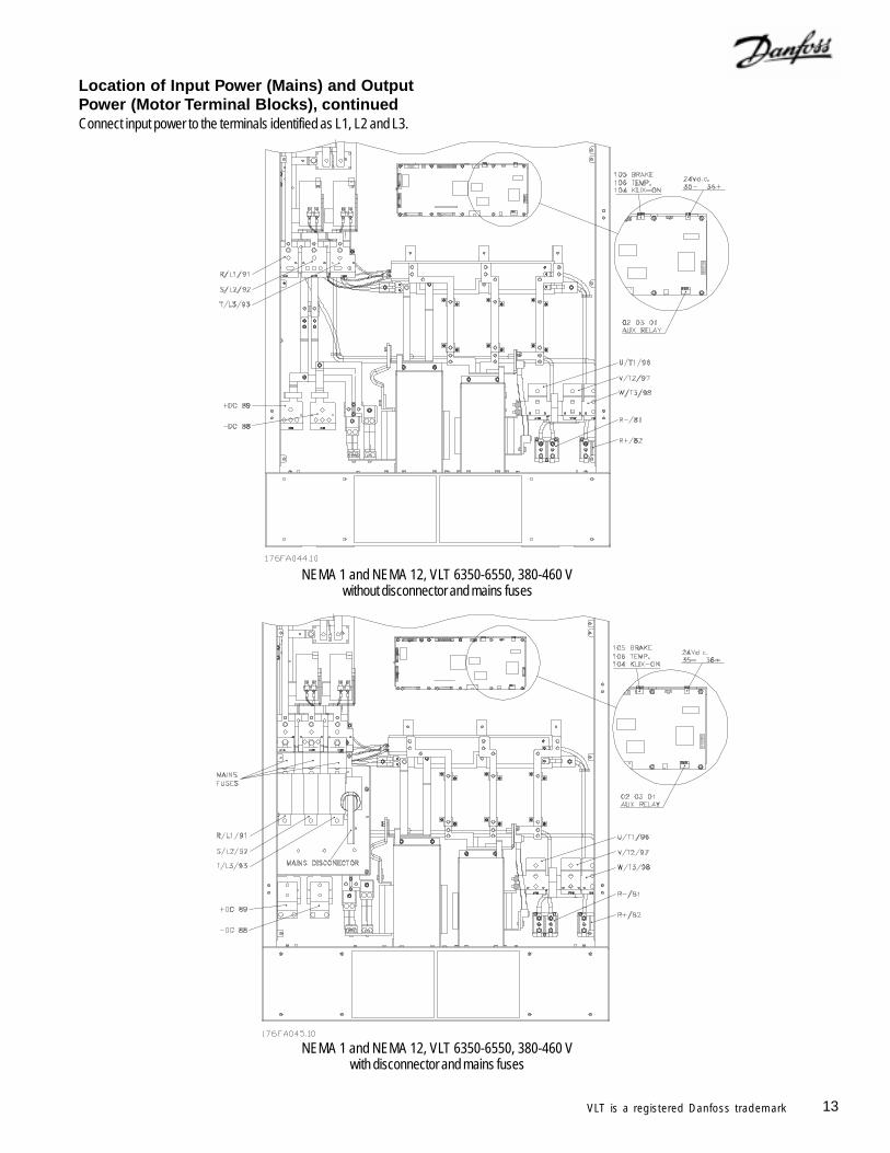
Location of Input Power (Mains) and OutputPower (Motor Terminal Blocks), continuedConnect input power to the terminals identified as L1, L2 and L3.
NEMA 1 and NEMA 12, VLT 6350-6550, 380-460 Vwithout disconnector and mains fuses
NEMA 1 and NEMA 12, VLT 6350-6550, 380-460 Vwith disconnector and mains fuses
14 VLT is a registered Danfoss trademark
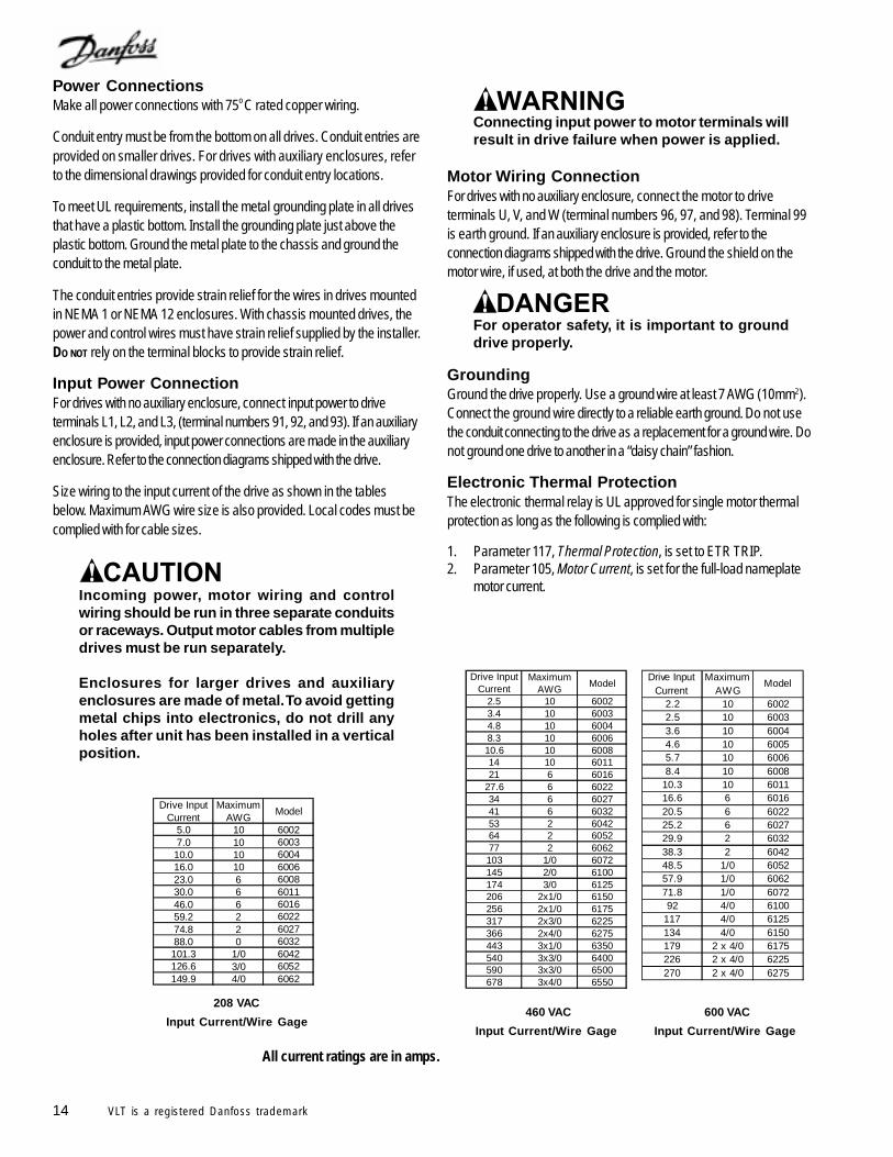
Power ConnectionsMake all power connections with 75o C rated copper wiring.
Conduit entry must be from the bottom on all drives. Conduit entries areprovided on smaller drives. For drives with auxiliary enclosures, referto the dimensional drawings provided for conduit entry locations.
To meet UL requirements, install the metal grounding plate in all drivesthat have a plastic bottom. Install the grounding plate just above theplastic bottom. Ground the metal plate to the chassis and ground theconduit to the metal plate.
The conduit entries provide strain relief for the wires in drives mountedin NEMA 1 or NEMA 12 enclosures. With chassis mounted drives, thepower and control wires must have strain relief supplied by the installer.DO NOT rely on the terminal blocks to provide strain relief.
Input Power ConnectionFor drives with no auxiliary enclosure, connect input power to driveterminals L1, L2, and L3, (terminal numbers 91, 92, and 93). If an auxiliaryenclosure is provided, input power connections are made in the auxiliaryenclosure. Refer to the connection diagrams shipped with the drive.
Size wiring to the input current of the drive as shown in the tablesbelow. Maximum AWG wire size is also provided. Local codes must becomplied with for cable sizes.
Incoming power, motor wiring and controlwiring should be run in three separate conduitsor raceways. Output motor cables from multipledrives must be run separately.
Enclosures for larger drives and auxiliaryenclosures are made of metal. To avoid gettingmetal chips into electronics, do not drill anyholes after unit has been installed in a verticalposition.
460 VAC
Input Current/Wire Gage
208 VAC
Input Current/Wire Gage
All current ratings are in amps.
Connecting input power to motor terminals willresult in drive failure when power is applied.
Motor Wiring ConnectionFor drives with no auxiliary enclosure, connect the motor to driveterminals U, V, and W (terminal numbers 96, 97, and 98). Terminal 99is earth ground. If an auxiliary enclosure is provided, refer to theconnection diagrams shipped with the drive. Ground the shield on themotor wire, if used, at both the drive and the motor.
GroundingGround the drive properly. Use a ground wire at least 7 AWG (10mm2).Connect the ground wire directly to a reliable earth ground. Do not usethe conduit connecting to the drive as a replacement for a ground wire. Donot ground one drive to another in a “daisy chain” fashion.
Electronic Thermal ProtectionThe electronic thermal relay is UL approved for single motor thermalprotection as long as the following is complied with:
1. Parameter 117, Thermal Protection, is set to ETR TRIP.2. Parameter 105, Motor Current, is set for the full-load nameplate
motor current.
For operator safety, it is important to grounddrive properly.
600 VAC
Input Current/Wire Gage
Drive Input Current
Maximum AWG
Model
2.2 10 60022.5 10 60033.6 10 60044.6 10 60055.7 10 60068.4 10 6008
10.3 10 601116.6 6 601620.5 6 602225.2 6 602729.9 2 603238.3 2 604248.5 1/0 605257.9 1/0 606271.8 1/0 607292 4/0 6100
117 4/0 6125134 4/0 6150179 2 x 4/0 6175226 2 x 4/0 6225270 2 x 4/0 6275
Drive Input Current
Maximum AWG
Model
5.0 10 60027.0 10 600310.0 10 600416.0 10 600623.0 6 600830.0 6 601146.0 6 601659.2 2 602274.8 2 602788.0 0 6032101.3 1/0 6042126.6 3/0 6052149.9 4/0 6062
Drive Input Current
Maximum AWG
Model
2.5 10 60023.4 10 60034.8 10 60048.3 10 600610.6 10 600814 10 601121 6 6016
27.6 6 602234 6 602741 6 603253 2 604264 2 605277 2 6062103 1/0 6072145 2/0 6100174 3/0 6125206 2x1/0 6150256 2x1/0 6175317 2x3/0 6225366 2x4/0 6275443 3x1/0 6350540 3x3/0 6400590 3x3/0 6500678 3x4/0 6550
15VLT is a registered Danfoss trademark
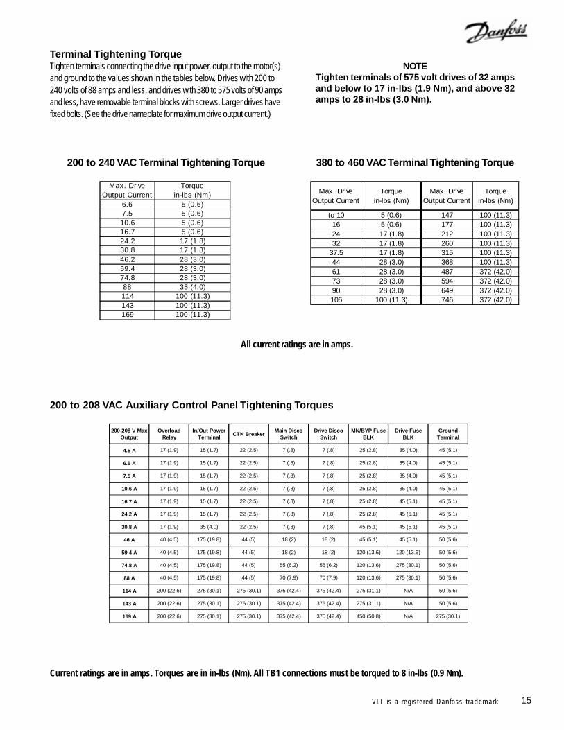
Current ratings are in amps. Torques are in in-lbs (Nm). All TB1 connections must be torqued to 8 in-lbs (0.9 Nm).
200 to 208 VAC Auxiliary Control Panel Tightening Torques
200 to 240 VAC Terminal Tightening Torque 380 to 460 VAC Terminal Tightening Torque
Max. Drive Output Current
Torque in-lbs (Nm)
6.6 5 (0.6)7.5 5 (0.6)10.6 5 (0.6)16.7 5 (0.6)24.2 17 (1.8)30.8 17 (1.8)46.2 28 (3.0)59.4 28 (3.0)74.8 28 (3.0)88 35 (4.0)114 100 (11.3)143 100 (11.3)169 100 (11.3)
Max. Drive Output Current
Torque in-lbs (Nm)
Max. Drive Output Current
Torque in-lbs (Nm)
to 10 5 (0.6) 147 100 (11.3)16 5 (0.6) 177 100 (11.3)24 17 (1.8) 212 100 (11.3)32 17 (1.8) 260 100 (11.3)
37.5 17 (1.8) 315 100 (11.3)44 28 (3.0) 368 100 (11.3)61 28 (3.0) 487 372 (42.0)73 28 (3.0) 594 372 (42.0)90 28 (3.0) 649 372 (42.0)106 100 (11.3) 746 372 (42.0)
Terminal Tightening TorqueTighten terminals connecting the drive input power, output to the motor(s)and ground to the values shown in the tables below. Drives with 200 to240 volts of 88 amps and less, and drives with 380 to 575 volts of 90 ampsand less, have removable terminal blocks with screws. Larger drives havefixed bolts. (See the drive nameplate for maximum drive output current.)
NOTETighten terminals of 575 volt drives of 32 ampsand below to 17 in-lbs (1.9 Nm), and above 32amps to 28 in-lbs (3.0 Nm).
All current ratings are in amps.
200-208 V Max Output
Overload Relay
In/Out Power Terminal
CTK BreakerMain Disco
SwitchDrive Disco
SwitchMN/BYP Fuse
BLKDrive Fuse
BLKGround
Terminal
4.6 A 17 (1.9) 15 (1.7) 22 (2.5) 7 (.8) 7 (.8) 25 (2.8) 35 (4.0) 45 (5.1)
6.6 A 17 (1.9) 15 (1.7) 22 (2.5) 7 (.8) 7 (.8) 25 (2.8) 35 (4.0) 45 (5.1)
7.5 A 17 (1.9) 15 (1.7) 22 (2.5) 7 (.8) 7 (.8) 25 (2.8) 35 (4.0) 45 (5.1)
10.6 A 17 (1.9) 15 (1.7) 22 (2.5) 7 (.8) 7 (.8) 25 (2.8) 35 (4.0) 45 (5.1)
16.7 A 17 (1.9) 15 (1.7) 22 (2.5) 7 (.8) 7 (.8) 25 (2.8) 45 (5.1) 45 (5.1)
24.2 A 17 (1.9) 15 (1.7) 22 (2.5) 7 (.8) 7 (.8) 25 (2.8) 45 (5.1) 45 (5.1)
30.8 A 17 (1.9) 35 (4.0) 22 (2.5) 7 (.8) 7 (.8) 45 (5.1) 45 (5.1) 45 (5.1)
46 A 40 (4.5) 175 (19.8) 44 (5) 18 (2) 18 (2) 45 (5.1) 45 (5.1) 50 (5.6)
59.4 A 40 (4.5) 175 (19.8) 44 (5) 18 (2) 18 (2) 120 (13.6) 120 (13.6) 50 (5.6)
74.8 A 40 (4.5) 175 (19.8) 44 (5) 55 (6.2) 55 (6.2) 120 (13.6) 275 (30.1) 50 (5.6)
88 A 40 (4.5) 175 (19.8) 44 (5) 70 (7.9) 70 (7.9) 120 (13.6) 275 (30.1) 50 (5.6)
114 A 200 (22.6) 275 (30.1) 275 (30.1) 375 (42.4) 375 (42.4) 275 (31.1) N/A 50 (5.6)
143 A 200 (22.6) 275 (30.1) 275 (30.1) 375 (42.4) 375 (42.4) 275 (31.1) N/A 50 (5.6)
169 A 200 (22.6) 275 (30.1) 275 (30.1) 375 (42.4) 375 (42.4) 450 (50.8) N/A 275 (30.1)
16 VLT is a registered Danfoss trademark
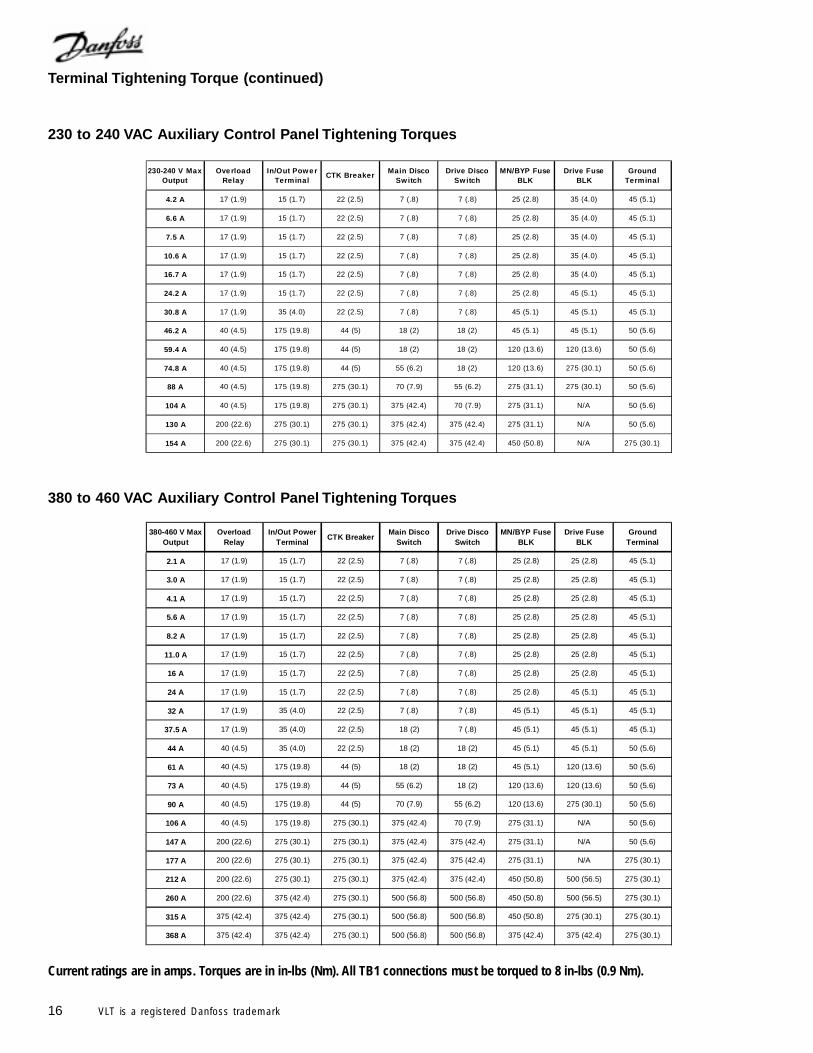
230 to 240 VAC Auxiliary Control Panel Tightening Torques
230-240 V Max Output
Ove rload Relay
In/Out Powe r Terminal
CTK BreakerMain Disco
SwitchDrive Disco
SwitchMN/BYP Fuse
BLKDrive Fuse
BLKGround
Terminal
4.2 A 17 (1.9) 15 (1.7) 22 (2.5) 7 (.8) 7 (.8) 25 (2.8) 35 (4.0) 45 (5.1)
6.6 A 17 (1.9) 15 (1.7) 22 (2.5) 7 (.8) 7 (.8) 25 (2.8) 35 (4.0) 45 (5.1)
7.5 A 17 (1.9) 15 (1.7) 22 (2.5) 7 (.8) 7 (.8) 25 (2.8) 35 (4.0) 45 (5.1)
10.6 A 17 (1.9) 15 (1.7) 22 (2.5) 7 (.8) 7 (.8) 25 (2.8) 35 (4.0) 45 (5.1)
16.7 A 17 (1.9) 15 (1.7) 22 (2.5) 7 (.8) 7 (.8) 25 (2.8) 35 (4.0) 45 (5.1)
24.2 A 17 (1.9) 15 (1.7) 22 (2.5) 7 (.8) 7 (.8) 25 (2.8) 45 (5.1) 45 (5.1)
30.8 A 17 (1.9) 35 (4.0) 22 (2.5) 7 (.8) 7 (.8) 45 (5.1) 45 (5.1) 45 (5.1)
46.2 A 40 (4.5) 175 (19.8) 44 (5) 18 (2) 18 (2) 45 (5.1) 45 (5.1) 50 (5.6)
59.4 A 40 (4.5) 175 (19.8) 44 (5) 18 (2) 18 (2) 120 (13.6) 120 (13.6) 50 (5.6)
74.8 A 40 (4.5) 175 (19.8) 44 (5) 55 (6.2) 18 (2) 120 (13.6) 275 (30.1) 50 (5.6)
88 A 40 (4.5) 175 (19.8) 275 (30.1) 70 (7.9) 55 (6.2) 275 (31.1) 275 (30.1) 50 (5.6)
104 A 40 (4.5) 175 (19.8) 275 (30.1) 375 (42.4) 70 (7.9) 275 (31.1) N/A 50 (5.6)
130 A 200 (22.6) 275 (30.1) 275 (30.1) 375 (42.4) 375 (42.4) 275 (31.1) N/A 50 (5.6)
154 A 200 (22.6) 275 (30.1) 275 (30.1) 375 (42.4) 375 (42.4) 450 (50.8) N/A 275 (30.1)
380-460 V Max Output
Overload Relay
In/Out Power Terminal
CTK BreakerMain Disco
SwitchDrive Disco
SwitchMN/BYP Fuse
BLKDrive Fuse
BLKGround
Terminal
2.1 A 17 (1.9) 15 (1.7) 22 (2.5) 7 (.8) 7 (.8) 25 (2.8) 25 (2.8) 45 (5.1)
3.0 A 17 (1.9) 15 (1.7) 22 (2.5) 7 (.8) 7 (.8) 25 (2.8) 25 (2.8) 45 (5.1)
4.1 A 17 (1.9) 15 (1.7) 22 (2.5) 7 (.8) 7 (.8) 25 (2.8) 25 (2.8) 45 (5.1)
5.6 A 17 (1.9) 15 (1.7) 22 (2.5) 7 (.8) 7 (.8) 25 (2.8) 25 (2.8) 45 (5.1)
8.2 A 17 (1.9) 15 (1.7) 22 (2.5) 7 (.8) 7 (.8) 25 (2.8) 25 (2.8) 45 (5.1)
11.0 A 17 (1.9) 15 (1.7) 22 (2.5) 7 (.8) 7 (.8) 25 (2.8) 25 (2.8) 45 (5.1)
16 A 17 (1.9) 15 (1.7) 22 (2.5) 7 (.8) 7 (.8) 25 (2.8) 25 (2.8) 45 (5.1)
24 A 17 (1.9) 15 (1.7) 22 (2.5) 7 (.8) 7 (.8) 25 (2.8) 45 (5.1) 45 (5.1)
32 A 17 (1.9) 35 (4.0) 22 (2.5) 7 (.8) 7 (.8) 45 (5.1) 45 (5.1) 45 (5.1)
37.5 A 17 (1.9) 35 (4.0) 22 (2.5) 18 (2) 7 (.8) 45 (5.1) 45 (5.1) 45 (5.1)
44 A 40 (4.5) 35 (4.0) 22 (2.5) 18 (2) 18 (2) 45 (5.1) 45 (5.1) 50 (5.6)
61 A 40 (4.5) 175 (19.8) 44 (5) 18 (2) 18 (2) 45 (5.1) 120 (13.6) 50 (5.6)
73 A 40 (4.5) 175 (19.8) 44 (5) 55 (6.2) 18 (2) 120 (13.6) 120 (13.6) 50 (5.6)
90 A 40 (4.5) 175 (19.8) 44 (5) 70 (7.9) 55 (6.2) 120 (13.6) 275 (30.1) 50 (5.6)
106 A 40 (4.5) 175 (19.8) 275 (30.1) 375 (42.4) 70 (7.9) 275 (31.1) N/A 50 (5.6)
147 A 200 (22.6) 275 (30.1) 275 (30.1) 375 (42.4) 375 (42.4) 275 (31.1) N/A 50 (5.6)
177 A 200 (22.6) 275 (30.1) 275 (30.1) 375 (42.4) 375 (42.4) 275 (31.1) N/A 275 (30.1)
212 A 200 (22.6) 275 (30.1) 275 (30.1) 375 (42.4) 375 (42.4) 450 (50.8) 500 (56.5) 275 (30.1)
260 A 200 (22.6) 375 (42.4) 275 (30.1) 500 (56.8) 500 (56.8) 450 (50.8) 500 (56.5) 275 (30.1)
315 A 375 (42.4) 375 (42.4) 275 (30.1) 500 (56.8) 500 (56.8) 450 (50.8) 275 (30.1) 275 (30.1)
368 A 375 (42.4) 375 (42.4) 275 (30.1) 500 (56.8) 500 (56.8) 375 (42.4) 375 (42.4) 275 (30.1)
380 to 460 VAC Auxiliary Control Panel Tightening Torques
Terminal Tightening Torque (continued)
Current ratings are in amps. Torques are in in-lbs (Nm). All TB1 connections must be torqued to 8 in-lbs (0.9 Nm).
17VLT is a registered Danfoss trademark
550-600 V Max Output
Overload Relay
In/Out Power Terminal
CTK BreakerMain Disco
SwitchDrive Disco
SwitchMN/BYP Fuse
BLKDrive Fuse
BLKGround
Terminal
1.7 A 17 (1.9) 15 (1.7) 50 (5.6) 7 (.8) 7 (.8) 25 (2.8) 25 (2.8) 45 (5.1)
2.4 A 17 (1.9) 15 (1.7) 50 (5.6) 7 (.8) 7 (.8) 25 (2.8) 25 (2.8) 45 (5.1)
2.7 A 17 (1.9) 15 (1.7) 50 (5.6) 7 (.8) 7 (.8) 25 (2.8) 25 (2.8) 45 (5.1)
3.9 A 17 (1.9) 15 (1.7) 50 (5.6) 7 (.8) 7 (.8) 25 (2.8) 25 (2.8) 45 (5.1)
6.1 A 17 (1.9) 15 (1.7) 50 (5.6) 7 (.8) 7 (.8) 25 (2.8) 25 (2.8) 45 (5.1)
9.0 A 17 (1.9) 15 (1.7) 50 (5.6) 7 (.8) 7 (.8) 25 (2.8) 25 (2.8) 45 (5.1)
11.0 A 17 (1.9) 15 (1.7) 50 (5.6) 7 (.8) 7 (.8) 25 (2.8) 25 (2.8) 45 (5.1)
17 A 17 (1.9) 15 (1.7) 50 (5.6) 7 (.8) 7 (.8) 25 (2.8) 45 (5.1) 45 (5.1)
22 A 17 (1.9) 15 (1.7) 50 (5.6) 7 (.8) 7 (.8) 45 (5.1) 45 (5.1) 45 (5.1)
27 A 17 (1.9) 35 (4.0) 50 (5.6) 7 (.8) 7 (.8) 45 (5.1) 45 (5.1) 45 (5.1)
32 A 17 (1.9) 35 (4.0) 50 (5.6) 18 (2) 18 (2) 45 (5.1) 120 (13.6) 45 (5.1)
41 A 40 (4.5) 35 (4.0) 50 (5.6) 18 (2) 18 (2) 45 (5.1) 120 (13.6) 50 (5.6)
52 A 40 (4.5) 175 (19.8) 50 (5.6) 70 (7.9) 55 (6.2) 120 (13.6) 120 (13.6) 50 (5.6)
62 A 40 (4.5) 175 (19.8) 50 (5.6) 70 (7.9) 55 (6.2) 120 (13.6) 120 (13.6) 50 (5.6)
77 A 40 (4.5) 175 (19.8) 275 (30.1) 70 (7.9) 55 (6.2) 120 (13.6) 120 (13.6) 50 (5.6)
99 A 40 (4.5) 175 (19.8) 275 (30.1) 375 (42.4) 70 (7.9) 275 (31.1) 275 (30.1) 50 (5.6)
125 A 200 (22.6) 275 (30.1) 275 (30.1) 375 (42.4) 375 (42.4) 275 (31.1) N/A 50 (5.6)
144 A 200 (22.6) 275 (30.1) 275 (30.1) 375 (42.4) 375 (42.4) 275 (31.1) N/A 275 (30.1)
192 A 200 (22.6) 275 (30.1) 275 (30.1) 375 (42.4) 375 (42.4) 450 (50.8) N/A 275 (30.1)
242 A 375 (42.4) 375 (42.4) 275 (30.1) 500 (56.8) 500 (56.8) 450 (50.8) 500 (56.5) 275 (30.1)
289 A 375 (42.4) 375 (42.4) 275 (30.1) 500 (56.8) 500 (56.8) 375 (42.4) 275 (30.1) 275 (30.1)
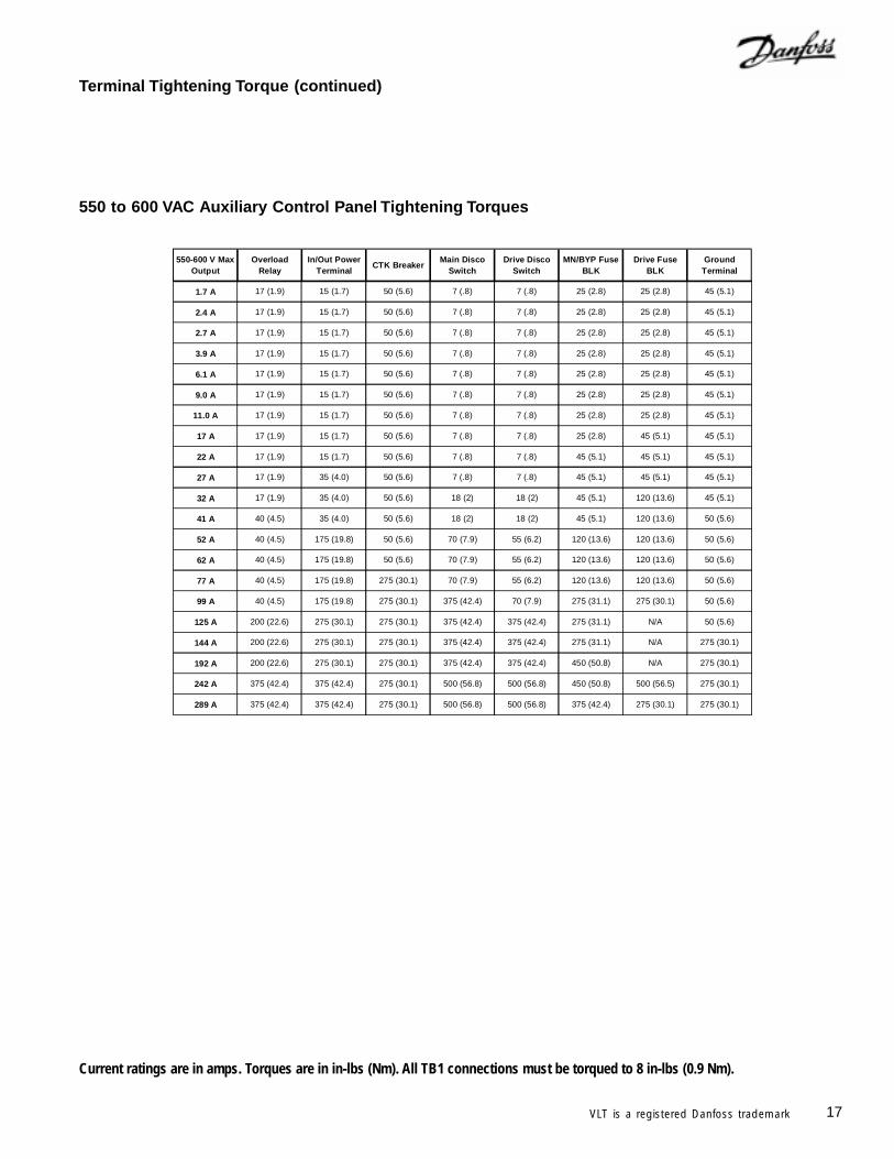
550 to 600 VAC Auxiliary Control Panel Tightening Torques
Terminal Tightening Torque (continued)
Current ratings are in amps. Torques are in in-lbs (Nm). All TB1 connections must be torqued to 8 in-lbs (0.9 Nm).
18 VLT is a registered Danfoss trademark
When multiple motors are used, VLT 6000 electronicthermal relay cannot be used to provide individualmotor protection. A separate motor overload mustbe supplied for each motor.
If the multiple motors are of significantly different sizes, starting problemsmay occur. This is because the higher electrical resistance of smallermotors will require more start voltage than larger motors.
NOTEAutomatic Motor Adaptation and AutomaticEnergy Optimization cannot be used formultiple motor installations.
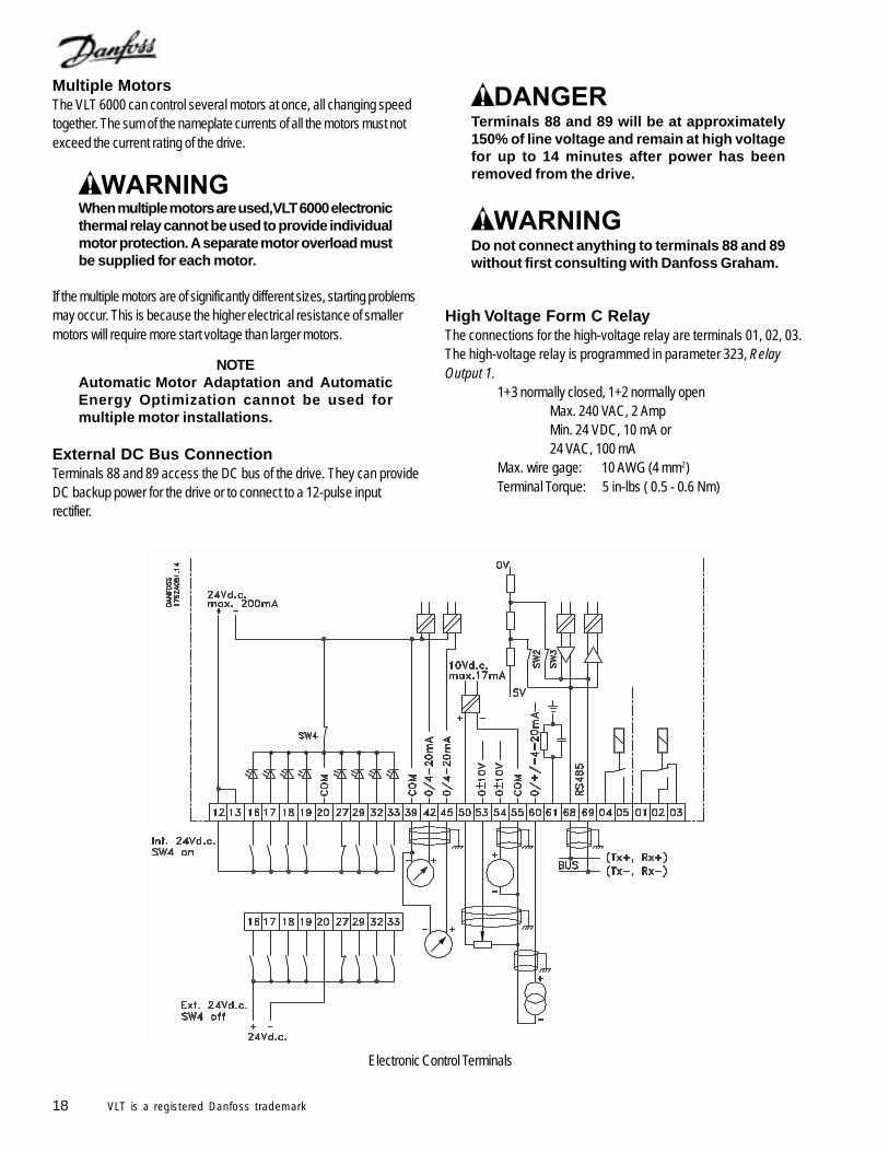
External DC Bus ConnectionTerminals 88 and 89 access the DC bus of the drive. They can provideDC backup power for the drive or to connect to a 12-pulse inputrectifier.
Terminals 88 and 89 will be at approximately150% of line voltage and remain at high voltagefor up to 14 minutes after power has beenremoved from the drive.
Do not connect anything to terminals 88 and 89without first consulting with Danfoss Graham.
High Voltage Form C RelayThe connections for the high-voltage relay are terminals 01, 02, 03.The high-voltage relay is programmed in parameter 323, RelayOutput 1.
1+3 normally closed, 1+2 normally openMax. 240 VAC, 2 AmpMin. 24 VDC, 10 mA or24 VAC, 100 mA
Max. wire gage: 10 AWG (4 mm2)Terminal Torque: 5 in-lbs ( 0.5 - 0.6 Nm)
Multiple MotorsThe VLT 6000 can control several motors at once, all changing speedtogether. The sum of the nameplate currents of all the motors must notexceed the current rating of the drive.
Electronic Control Terminals
19VLT is a registered Danfoss trademark
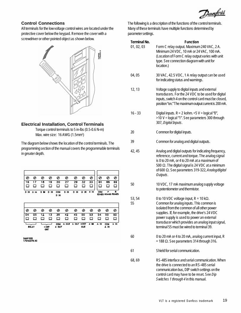
Control ConnectionsAll terminals for the low voltage control wires are located under theprotective cover below the keypad. Remove the cover with ascrewdriver or other pointed object as shown below.
Electrical Installation, Control TerminalsTorque control terminals to 5 in-lbs (0.5-0.6 N-m)Max. wire size: 16 AWG (1.5mm2)
The diagram below shows the location of the control terminals. Theprogramming section of the manual covers the programmable terminalsin greater depth.
The following is a description of the functions of the control terminals.Many of these terminals have multiple functions determined byparameter settings.
Terminal No. Function01, 02, 03 Form C relay output. Maximum 240 VAC, 2 A.
Minimum 24 VDC, 10 mA or 24 VAC, 100 mA.(Location of Form C relay output varies with unittype. See connection diagram with unit forlocation.)
04, 05 30 VAC, 42.5 VDC, 1 A relay output can be usedfor indicating status and warnings.
12, 13 Voltage supply to digital inputs and externaltransducers. For the 24 VDC to be used for digitalinputs, switch 4 on the control card must be closed,position “on.” The maximum output current is 200 mA.
16 - 33 Digital inputs. R = 2 kohm. <5 V = logical “0”,
>10 V = logical “1”. See parameters 300 through307, Digital Inputs.
20 Common for digital inputs.
39 Common for analog and digital outputs.
42, 45 Analog and digital outputs for indicating frequency,reference, current and torque. The analog signalis 0 to 20 mA, or 4 to 20 mA at a maximum of500 Ω. The digital signal is 24 VDC at a minimumof 600 Ω. See parameters 319-322, Analog/digitalOutputs.
50 10 VDC, 17 mA maximum analog supply voltageto potentiometer and thermistor.
53, 54 0 to 10 VDC voltage input, R = 10 kΩ.55 Common for analog inputs. This common is
isolated from the common of all other powersupplies. If, for example, the drive’s 24 VDCpower supply is used to power an externaltransducer which provides an analog input signal,terminal 55 must be wired to terminal 39.
60 0 to 20 mA or 4 to 20 mA, analog current input, R= 188 Ω. See parameters 314 through 316.
61 Shield for serial communication.
68, 69 RS-485 interface and serial communication. Whenthe drive is connected to an RS-485 serialcommunication bus, DIP switch settings on thecontrol card may have to be reset. See DipSwitches 1 through 4 in this manual.
20 VLT is a registered Danfoss trademark
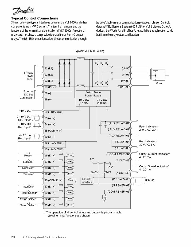
Typical Control ConnectionsShown below are typical interfaces between the VLT 6000 and othercomponents in an HVAC system. The terminal numbers and thefunctions of the terminals are identical on all VLT 6000s. An optionalrelay card, not shown, can provide four additional Form C outputrelays. The RS-485 connections allow direct communication through
91 (L1)
92 (L2)
93 (L3)
(U) 96
(V) 97
(W) 98
(AUX RELAY) 01
( AUX RELAY) 02
(AUX RELAY) 03
Fault Indication*240 V AC, 2 A
(PE) 95
(RELAY) 04
(RELAY) 05
Run Indication*30 V AC, 1 A
(COM A OUT) 39
(A OUT) 42
(A OUT) 45
Output Current Indication*4 - 20 mA
88 (-)
89 (+)
99 (PE)Motor
3 PhasePower
Input
ExternalDC Bus
Connection
Output Speed Indication*4 - 20 mA
Switch ModePower Supply
24 V DC200 mA
+ -
(P RS-485) 68
(N RS-485) 69
(COM RS-485) 61
+
-RS-485
SW2 SW3
5 V
10 V DC17 mA
+ -
50 (+10 V OUT)
60 (A IN)
+10 V DC
0 - 10 V DCRef. Input*
0 - 10 V DCRef. Input*
4 - 20 mARef. Input*
54 (A IN)
55 (COM A IN)
53 (A IN)
12 (+24 V OUT)
13 (+24 V OUT)
SW4
Preset Speed*
Setup Select*
Setup Select*
Reset*
Lockout*
Run/Stop*
Reverse*
Interlock*
16 (D IN)
17 (D IN)
18 (D IN)
19 (D IN)
20 (COM D IN)
27 (D IN)
29 (D IN)
32 (D IN)
33 (D IN)
0 V
RS-485Interface
Typical* VLT 6000 Wiring
* The operation of all control inputs and outputs is programmable.* Typical terminal functions are shown.
the drive’s built-in serial communication protocols: Johnson ControlsMetasys® N2, Siemens System 600 FLN®, or VLT Software Dialog®.Modbus, LonWorks® and Profibus® are available through option cardsthat fit into the relay output card location.
21VLT is a registered Danfoss trademark
Incoming power, motor wiring and controlwiring should be run in three separate conduitsor raceways.
Electrical Installation, Control Wiring
Torque: 5 - 6 in-lbsScrew size: M3
Shielded control wires are recommended. To reduce interference fromelectrical noise, ground the cable shield at a cable clamp, as shownbelow, at both ends. Connect the shield to the grounded clamp. Verylong control wires may create 60 Hz interference. To resolve this,connect one end of the shield to earth with a 0.1 µF capacitor, keepingthe leads as short as possible. If interference persists, disconnect thegrounded shield connection at the end opposite to the drive.
DIP Switches 1 through 4DIP switches are located on the control card.
They are used for serial communication and the common of digitalinputs 16 through 33. The switch positions shown are the factorysettings.
Switch 1 is not used.
Switches 2 and 3 are used for terminating serial communication. On thefirst and last drive in a multiple device network, or on the only drive of asingle drive network, switches 2 and 3 must be ON (the default setting).On all other drives in a multiple device network, set switches 2 and 3 toOFF.
Switch 4 separates the common for the internal 24 VDC supply from thecommon of the external 24 VDC supply. Normally this switch is ON andthe power supply is present at terminals 12 and 13. Set Switch 4 to theOFF position when an external 24 VDC supply is used.
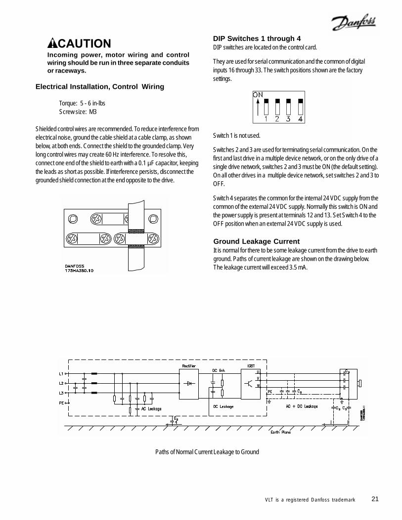
Paths of Normal Current Leakage to Ground
Ground Leakage CurrentIt is normal for there to be some leakage current from the drive to earthground. Paths of current leakage are shown on the drawing below.The leakage current will exceed 3.5 mA.
22 VLT is a registered Danfoss trademark
Electrical NoiseIn general, electrical noise can be divided into two forms: wire-borneelectromagnetic interference (EMI), and radiating radio frequencyinterference (RFI).
Using shielded motor cables reduces RFI but increases EMI. This isbecause shielded wires have a greater capacitance than unshieldedwires. Unshielded input power connections to the drive generate morenoise in the radio frequency range on the AC line. The shield reducesthe radiated noise, but increases the low-frequency electromagneticnoise on the AC line. But, since the noise current is taken back to theunit through the shield, only a small electromagnetic field is generatedfrom shielded motor wires.
With an EMI filter, the noise level on the AC line will be reduced toabout the same level for shielded and unshielded wires alike.
Connect the motor wiring shield, if used, in the enclosure of the drive aswell as at the motor. Use shield brackets to avoid “pigtail” shield ends.Even short “pigtails” increase the shield’s impedance at higherfrequencies, which reduces the shield’s effect and increases the noiseproduced.
It is generally easier and less complicated to use unshielded motorwires than shielded cables. If unshielded wires are used, the RFI willbe greater. But, since the strength of the radiated signal decreases withdistance from the signal source, radiated noise is generally not aproblem.
To reduce the noise level from the total system (drive + installation)make the motor wiring as short as possible.
Provide separate conduits, or raceways, for power, motor and controlwiring to provide the greatest immunity from distortion.
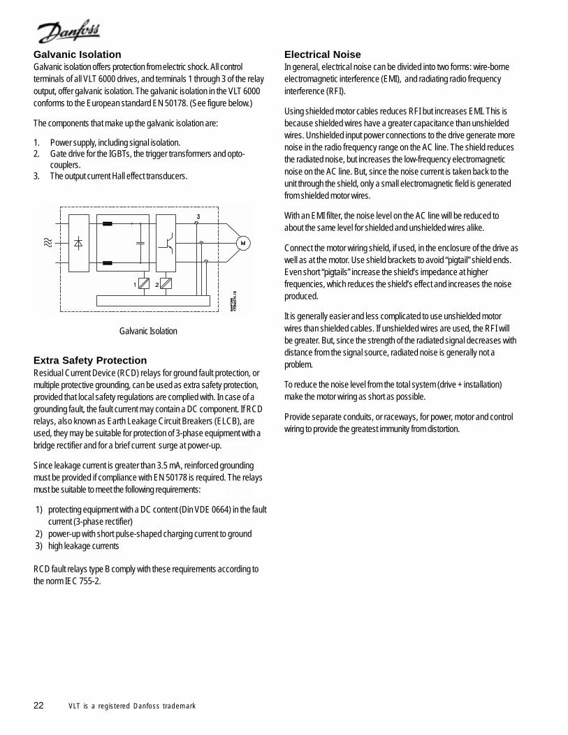
Galvanic IsolationGalvanic isolation offers protection from electric shock. All controlterminals of all VLT 6000 drives, and terminals 1 through 3 of the relayoutput, offer galvanic isolation. The galvanic isolation in the VLT 6000conforms to the European standard EN 50178. (See figure below.)
The components that make up the galvanic isolation are:
1. Power supply, including signal isolation.2. Gate drive for the IGBTs, the trigger transformers and opto-
couplers.3. The output current Hall effect transducers.
Extra Safety ProtectionResidual Current Device (RCD) relays for ground fault protection, ormultiple protective grounding, can be used as extra safety protection,provided that local safety regulations are complied with. In case of agrounding fault, the fault current may contain a DC component. If RCDrelays, also known as Earth Leakage Circuit Breakers (ELCB), areused, they may be suitable for protection of 3-phase equipment with abridge rectifier and for a brief current surge at power-up.
Since leakage current is greater than 3.5 mA, reinforced groundingmust be provided if compliance with EN 50178 is required. The relaysmust be suitable to meet the following requirements:
1) protecting equipment with a DC content (Din VDE 0664) in the faultcurrent (3-phase rectifier)
2) power-up with short pulse-shaped charging current to ground3) high leakage currents
RCD fault relays type B comply with these requirements according tothe norm IEC 755-2.
Galvanic Isolation
23VLT is a registered Danfoss trademark
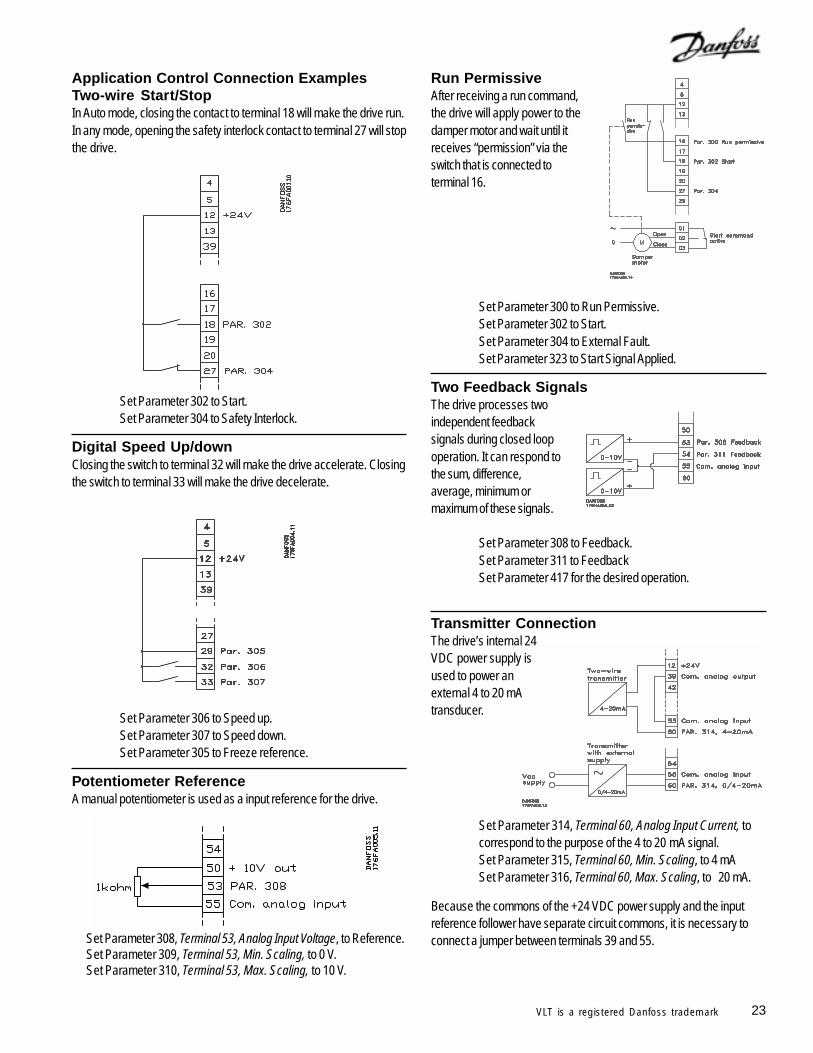
Application Control Connection ExamplesTwo-wire Start/StopIn Auto mode, closing the contact to terminal 18 will make the drive run.In any mode, opening the safety interlock contact to terminal 27 will stopthe drive.
Set Parameter 302 to Start.Set Parameter 304 to Safety Interlock.
Digital Speed Up/downClosing the switch to terminal 32 will make the drive accelerate. Closingthe switch to terminal 33 will make the drive decelerate.
Set Parameter 306 to Speed up.Set Parameter 307 to Speed down.Set Parameter 305 to Freeze reference.
Potentiometer ReferenceA manual potentiometer is used as a input reference for the drive.
Set Parameter 308, Terminal 53, Analog Input Voltage, to Reference.Set Parameter 309, Terminal 53, Min. Scaling, to 0 V.Set Parameter 310, Terminal 53, Max. Scaling, to 10 V.
Run PermissiveAfter receiving a run command,the drive will apply power to thedamper motor and wait until itreceives “permission” via theswitch that is connected toterminal 16.
Set Parameter 300 to Run Permissive.Set Parameter 302 to Start.Set Parameter 304 to External Fault.Set Parameter 323 to Start Signal Applied.
Two Feedback SignalsThe drive processes twoindependent feedbacksignals during closed loopoperation. It can respond tothe sum, difference,average, minimum ormaximum of these signals.
Set Parameter 308 to Feedback.Set Parameter 311 to FeedbackSet Parameter 417 for the desired operation.
Transmitter ConnectionThe drive’s internal 24VDC power supply isused to power anexternal 4 to 20 mAtransducer.
Set Parameter 314, Terminal 60, Analog Input Current, tocorrespond to the purpose of the 4 to 20 mA signal.Set Parameter 315, Terminal 60, Min. Scaling, to 4 mASet Parameter 316, Terminal 60, Max. Scaling, to 20 mA.
Because the commons of the +24 VDC power supply and the inputreference follower have separate circuit commons, it is necessary toconnect a jumper between terminals 39 and 55.
24 VLT is a registered Danfoss trademark
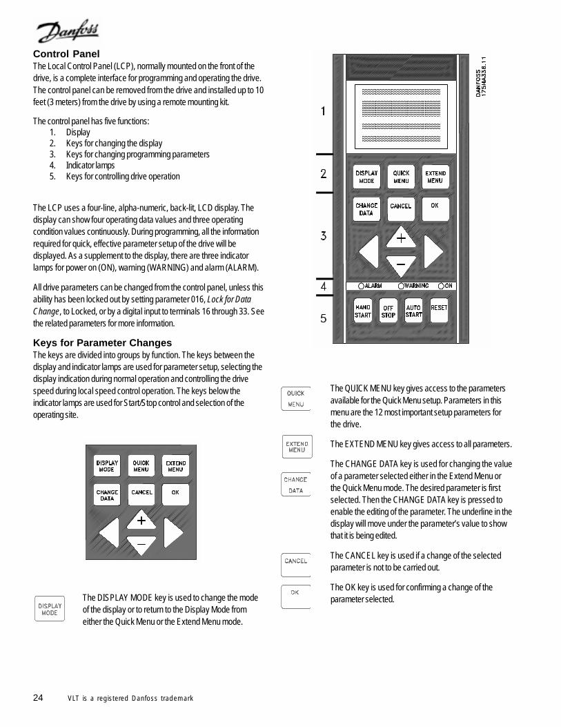
Control PanelThe Local Control Panel (LCP), normally mounted on the front of thedrive, is a complete interface for programming and operating the drive.The control panel can be removed from the drive and installed up to 10feet (3 meters) from the drive by using a remote mounting kit.
The control panel has five functions:1. Display2. Keys for changing the display3. Keys for changing programming parameters4. Indicator lamps5. Keys for controlling drive operation
The LCP uses a four-line, alpha-numeric, back-lit, LCD display. Thedisplay can show four operating data values and three operatingcondition values continuously. During programming, all the informationrequired for quick, effective parameter setup of the drive will bedisplayed. As a supplement to the display, there are three indicatorlamps for power on (ON), warning (WARNING) and alarm (ALARM).
All drive parameters can be changed from the control panel, unless thisability has been locked out by setting parameter 016, Lock for DataChange, to Locked, or by a digital input to terminals 16 through 33. Seethe related parameters for more information.
Keys for Parameter ChangesThe keys are divided into groups by function. The keys between thedisplay and indicator lamps are used for parameter setup, selecting thedisplay indication during normal operation and controlling the drivespeed during local speed control operation. The keys below theindicator lamps are used for Start/Stop control and selection of theoperating site.
The DISPLAY MODE key is used to change the modeof the display or to return to the Display Mode fromeither the Quick Menu or the Extend Menu mode.
The QUICK MENU key gives access to the parametersavailable for the Quick Menu setup. Parameters in thismenu are the 12 most important setup parameters forthe drive.
The EXTEND MENU key gives access to all parameters.
The CHANGE DATA key is used for changing the valueof a parameter selected either in the Extend Menu orthe Quick Menu mode. The desired parameter is firstselected. Then the CHANGE DATA key is pressed toenable the editing of the parameter. The underline in thedisplay will move under the parameter’s value to showthat it is being edited.
The CANCEL key is used if a change of the selectedparameter is not to be carried out.
The OK key is used for confirming a change of theparameter selected.
25VLT is a registered Danfoss trademark
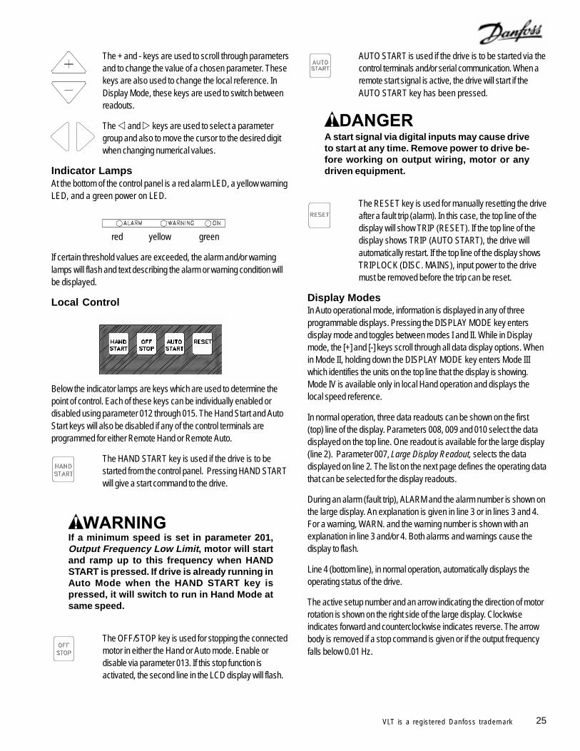
The + and - keys are used to scroll through parametersand to change the value of a chosen parameter. Thesekeys are also used to change the local reference. InDisplay Mode, these keys are used to switch betweenreadouts.
The and keys are used to select a parametergroup and also to move the cursor to the desired digitwhen changing numerical values.
Indicator LampsAt the bottom of the control panel is a red alarm LED, a yellow warningLED, and a green power on LED.
red yellow green
If certain threshold values are exceeded, the alarm and/or warninglamps will flash and text describing the alarm or warning condition willbe displayed.
Local Control
Below the indicator lamps are keys which are used to determine thepoint of control. Each of these keys can be individually enabled ordisabled using parameter 012 through 015. The Hand Start and AutoStart keys will also be disabled if any of the control terminals areprogrammed for either Remote Hand or Remote Auto.
The HAND START key is used if the drive is to bestarted from the control panel. Pressing HAND STARTwill give a start command to the drive.
If a minimum speed is set in parameter 201,Output Frequency Low Limit, motor will startand ramp up to this frequency when HANDSTART is pressed. If drive is already running inAuto Mode when the HAND START key ispressed, it will switch to run in Hand Mode atsame speed.
The OFF/STOP key is used for stopping the connectedmotor in either the Hand or Auto mode. Enable ordisable via parameter 013. If this stop function isactivated, the second line in the LCD display will flash.
AUTO START is used if the drive is to be started via thecontrol terminals and/or serial communication. When aremote start signal is active, the drive will start if theAUTO START key has been pressed.
A start signal via digital inputs may cause driveto start at any time. Remove power to drive be-fore working on output wiring, motor or anydriven equipment.
The RESET key is used for manually resetting the driveafter a fault trip (alarm). In this case, the top line of thedisplay will show TRIP (RESET). If the top line of thedisplay shows TRIP (AUTO START), the drive willautomatically restart. If the top line of the display showsTRIPLOCK (DISC. MAINS), input power to the drivemust be removed before the trip can be reset.
Display ModesIn Auto operational mode, information is displayed in any of threeprogrammable displays. Pressing the DISPLAY MODE key entersdisplay mode and toggles between modes I and II. While in Displaymode, the [+] and [-] keys scroll through all data display options. Whenin Mode II, holding down the DISPLAY MODE key enters Mode IIIwhich identifies the units on the top line that the display is showing.Mode IV is available only in local Hand operation and displays thelocal speed reference.
In normal operation, three data readouts can be shown on the first(top) line of the display. Parameters 008, 009 and 010 select the datadisplayed on the top line. One readout is available for the large display(line 2). Parameter 007, Large Display Readout, selects the datadisplayed on line 2. The list on the next page defines the operating datathat can be selected for the display readouts.
During an alarm (fault trip), ALARM and the alarm number is shown onthe large display. An explanation is given in line 3 or in lines 3 and 4.For a warning, WARN. and the warning number is shown with anexplanation in line 3 and/or 4. Both alarms and warnings cause thedisplay to flash.
Line 4 (bottom line), in normal operation, automatically displays theoperating status of the drive.
The active setup number and an arrow indicating the direction of motorrotation is shown on the right side of the large display. Clockwiseindicates forward and counterclockwise indicates reverse. The arrowbody is removed if a stop command is given or if the output frequencyfalls below 0.01 Hz.
26 VLT is a registered Danfoss trademark
The table below gives the operating data options for the first andsecond lines of the display.
Data Item: Unit:Resulting reference, % %Resulting reference unit chosen in par. 415Frequency Hz% of maximum output frequency %Motor current APower kWPower HPOutput energy kWhHours run hoursUser defined readout unit chosen in par. 006Setpoint 1 unit chosen in par. 415Setpoint 2 unit chosen in par. 415Feedback 1 unit chosen in par. 415Feedback 2 unit chosen in par. 415Feedback unit chosen in par. 415Motor voltage VDC link voltage VThermal load on motor %Thermal load on VLT %Input status, digital input binary codeInput status, analog terminal 53 VInput status, analog terminal 54 VInput status, analog terminal 60 mAPulse reference HzExternal reference %Heat sink temperature oC
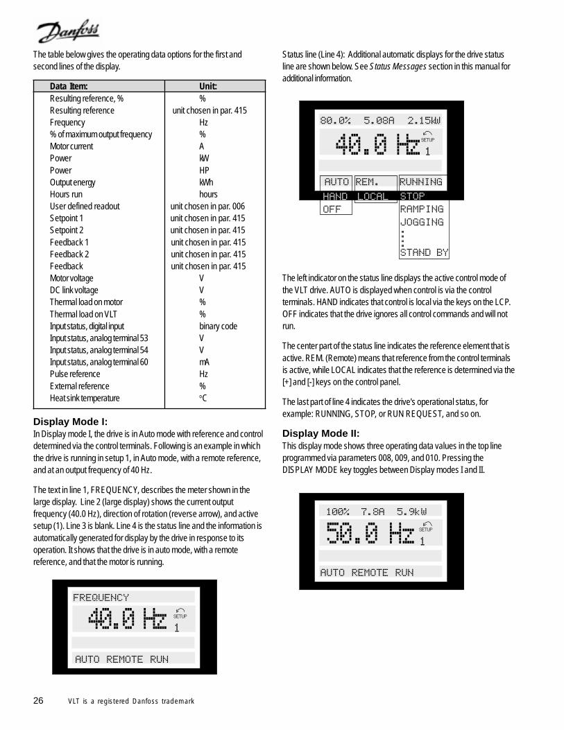
Display Mode I:In Display mode I, the drive is in Auto mode with reference and controldetermined via the control terminals. Following is an example in whichthe drive is running in setup 1, in Auto mode, with a remote reference,and at an output frequency of 40 Hz.
The text in line 1, FREQUENCY, describes the meter shown in thelarge display. Line 2 (large display) shows the current outputfrequency (40.0 Hz), direction of rotation (reverse arrow), and activesetup (1). Line 3 is blank. Line 4 is the status line and the information isautomatically generated for display by the drive in response to itsoperation. It shows that the drive is in auto mode, with a remotereference, and that the motor is running.
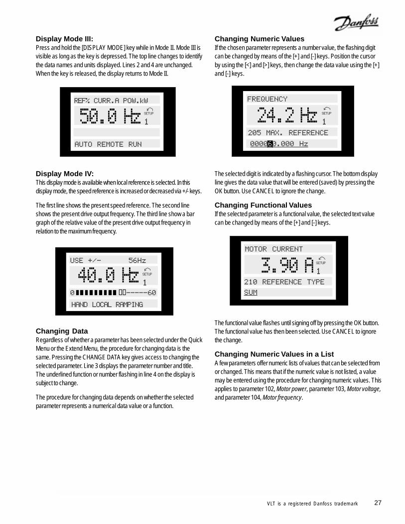
Status line (Line 4): Additional automatic displays for the drive statusline are shown below. See Status Messages section in this manual foradditional information.
The left indicator on the status line displays the active control mode ofthe VLT drive. AUTO is displayed when control is via the controlterminals. HAND indicates that control is local via the keys on the LCP.OFF indicates that the drive ignores all control commands and will notrun.
The center part of the status line indicates the reference element that isactive. REM. (Remote) means that reference from the control terminalsis active, while LOCAL indicates that the reference is determined via the[+] and [-] keys on the control panel.
The last part of line 4 indicates the drive's operational status, forexample: RUNNING, STOP, or RUN REQUEST, and so on.
Display Mode II:This display mode shows three operating data values in the top lineprogrammed via parameters 008, 009, and 010. Pressing theDISPLAY MODE key toggles between Display modes I and II.
! "
##
27VLT is a registered Danfoss trademark
Changing DataRegardless of whether a parameter has been selected under the QuickMenu or the Extend Menu, the procedure for changing data is thesame. Pressing the CHANGE DATA key gives access to changing theselected parameter. Line 3 displays the parameter number and title.The underlined function or number flashing in line 4 on the display issubject to change.
The procedure for changing data depends on whether the selectedparameter represents a numerical data value or a function.
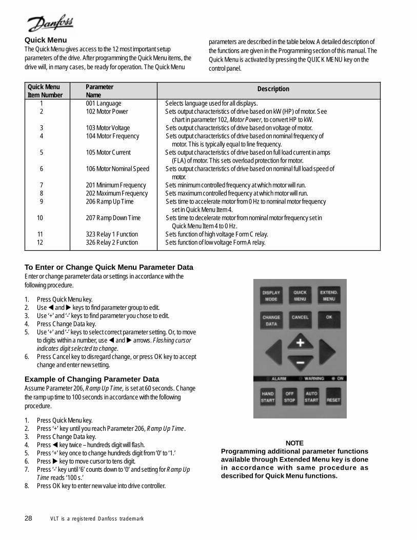
Display Mode III:Press and hold the [DISPLAY MODE] key while in Mode II. Mode III isvisible as long as the key is depressed. The top line changes to identifythe data names and units displayed. Lines 2 and 4 are unchanged.When the key is released, the display returns to Mode II.
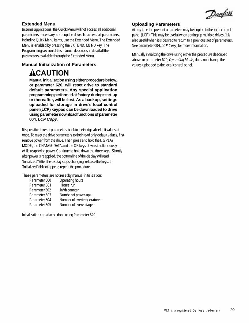
Display Mode IV:This display mode is available when local reference is selected. In thisdisplay mode, the speed reference is increased or decreased via +/- keys.
The first line shows the present speed reference. The second lineshows the present drive output frequency. The third line show a bargraph of the relative value of the present drive output frequency inrelation to the maximum frequency.
$%&'
##
((&&&&&'
Changing Numeric ValuesIf the chosen parameter represents a number value, the flashing digitcan be changed by means of the [+] and [-] keys. Position the cursorby using the [<] and [>] keys, then change the data value using the [+]and [-] keys.
The selected digit is indicated by a flashing cursor. The bottom displayline gives the data value that will be entered (saved) by pressing theOK button. Use CANCEL to ignore the change.
Changing Functional ValuesIf the selected parameter is a functional value, the selected text valuecan be changed by means of the [+] and [-] keys.
The functional value flashes until signing off by pressing the OK button.The functional value has then been selected. Use CANCEL to ignorethe change.
Changing Numeric Values in a ListA few parameters offer numeric lists of values that can be selected fromor changed. This means that if the numeric value is not listed, a valuemay be entered using the procedure for changing numeric values. Thisapplies to parameter 102, Motor power, parameter 103, Motor voltage,and parameter 104, Motor frequency.
)
'
*
28 VLT is a registered Danfoss trademark
Quick MenuThe Quick Menu gives access to the 12 most important setupparameters of the drive. After programming the Quick Menu items, thedrive will, in many cases, be ready for operation. The Quick Menu
Quick Menu Parameter DescriptionItem Number Name
1 001 Language Selects language used for all displays.2 102 Motor Power Sets output characteristics of drive based on kW (HP) of motor. See
chart in parameter 102, Motor Power, to convert HP to kW.3 103 Motor Voltage Sets output characteristics of drive based on voltage of motor.4 104 Motor Frequency Sets output characteristics of drive based on nominal frequency of
motor. This is typically equal to line frequency.5 105 Motor Current Sets output characteristics of drive based on full load current in amps
(FLA) of motor. This sets overload protection for motor.6 106 Motor Nominal Speed Sets output characteristics of drive based on nominal full load speed of
motor.7 201 Minimum Frequency Sets minimum controlled frequency at which motor will run.8 202 Maximum Frequency Sets maximum controlled frequency at which motor will run.9 206 Ramp Up Time Sets time to accelerate motor from 0 Hz to nominal motor frequency
set in Quick Menu Item 4.10 207 Ramp Down Time Sets time to decelerate motor from nominal motor frequency set in
Quick Menu Item 4 to 0 Hz.11 323 Relay 1 Function Sets function of high voltage Form C relay.12 326 Relay 2 Function Sets function of low voltage Form A relay.
To Enter or Change Quick Menu Parameter DataEnter or change parameter data or settings in accordance with thefollowing procedure.
1. Press Quick Menu key.2. Use and keys to find parameter group to edit.3. Use ‘+’ and ‘-’ keys to find parameter you chose to edit.4. Press Change Data key.5. Use ‘+’ and ‘-’ keys to select correct parameter setting. Or, to move
to digits within a number, use and arrows. Flashing cursorindicates digit selected to change.
6. Press Cancel key to disregard change, or press OK key to acceptchange and enter new setting.
Example of Changing Parameter DataAssume Parameter 206, Ramp Up Time, is set at 60 seconds. Changethe ramp up time to 100 seconds in accordance with the followingprocedure.
1. Press Quick Menu key.2. Press ‘+’ key until you reach Parameter 206, Ramp Up Time.3. Press Change Data key.4. Press key twice – hundreds digit will flash.5. Press ‘+’ key once to change hundreds digit from ‘0’ to ‘1.’6. Press key to move cursor to tens digit.7. Press ‘-’ key until ‘6’ counts down to ‘0’ and setting for Ramp Up
Time reads ‘100 s.’8. Press OK key to enter new value into drive controller.
NOTEProgramming additional parameter functionsavailable through Extended Menu key is donein accordance with same procedure asdescribed for Quick Menu functions.
parameters are described in the table below. A detailed description ofthe functions are given in the Programming section of this manual. TheQuick Menu is activated by pressing the QUICK MENU key on thecontrol panel.
29VLT is a registered Danfoss trademark
Extended MenuIn some applications, the Quick Menu will not access all additionalparameters necessary to set up the drive. To access all parameters,including Quick Menu items, use the Extended Menu. The ExtendedMenu is enabled by pressing the EXTEND. MENU key. TheProgramming section of this manual describes in detail all theparameters available through the Extended Menu.
Manual Initialization of Parameters
Manual initialization using either procedure below,or parameter 620, will reset drive to standarddefault parameters. Any special applicationprogramming performed at factory, during start-upor thereafter, will be lost. As a backup, settingsuploaded for storage in drive’s local controlpanel (LCP) keypad can be downloaded to driveusing parameter download functions of parameter004, LCP Copy.
It is possible to reset parameters back to their original default values atonce. To reset the drive parameters to their read only default values, firstremove power from the drive. Then press and hold the DISPLAYMODE, the CHANGE DATA and the OK keys down simultaneouslywhile reapplying power. Continue to hold down the three keys. Shortlyafter power is reapplied, the bottom line of the display will read“Initialized.” After the display stops changing, release the keys. If“Initialized” did not appear, repeat the procedure.
These parameters are not reset by manual initialization:Parameter 600 Operating hoursParameter 601 Hours runParameter 602 kWh counterParameter 603 Number of power-upsParameter 604 Number of overtemperaturesParameter 605 Number of overvoltages
Initialization can also be done using Parameter 620.
Uploading ParametersAt any time the present parameters may be copied to the local controlpanel (LCP). This may be useful when setting up multiple drives. It isalso useful when it is desired to return to a previous set of parameters.See parameter 004, LCP Copy, for more information.
Manually initializing the drive using either the procedure describedabove or parameter 620, Operating Mode, does not change thevalues uploaded to the local control panel.
30 VLT is a registered Danfoss trademark
VLT 6000 Start-Up
Pre-installation Checks1. Compare drive model number to what was ordered.2. Ensure each of following are rated for same voltage:
• Drive• Power line• Motor
3. Record following motor data:• Voltage• Frequency• Full load current• Full load speed• Power — convert HP to kW (See conversion table in parameter
102, Motor Power, in this manual.)4. Ensure that rated drive current is equal to or greater than total full
load current.• For multiple motor operations, add up full load current ratings of
all motors.• Drive can be at most one size smaller than motor.• If drive rating is less than motor, full motor output cannot be achieved.
5. Check motor wiring:• Any disconnect between drive and motor should be interlocked
to drive safety interlock circuit to avoid unwanted drive trips.• No power factor correction capacitors can be connected between
drive and motor.• Two speed motors must be wired permanently for full speed.• Y-start, -run motors must be wired permanently for run.
Installation Checks1. Input fusing in power supply for all drives must be provided (see
Input Fuses section in this manual).2. Environmental concerns — for standard NEMA 1 drive:
• Clean air supply• Dry air (max 95% relative humidity, non-condensing)• 14oF to 104oF ambient temperature operating range, or as rated• 3,300 foot maximum elevation with no derating
3. Mounting• Vertical• Drives with heat sink fins exposed in back of unit must be
mounted against a solid surface (see Clearances section in thismanual).
• Keep any construction dirt out of drive.4. Wiring
• Wire drive in accordance with instructions and diagrams receivedwith drive.
• Separate conduits must be provided to drive for input power,output power, and control wiring.
• Note that safety interlock and remote run/stop circuitry is 115 VACfor drives with bypasses.
• Use knockouts or conduit entry plates. Avoid metal shavings in cabinet.
• Protect signal wires from noise.• Ground each drive individually.• Double check input and output power wiring for correct location.
Setting Up Drive for Motor StartEnter motor nameplate data into drive through Quick Menu.1. Parameter 101:
• If one motor is connected to drive, set to AEO FUNCTION.• If more than one motor connected to drive, set to MULTIPLE
MOTORS. (Parameter 108, MULTIPLE MOTOR STARTINGVOLTAGE should be adjusted later to provide reliable starts andminimum starting current.)
2. Parameter 102, MOTOR POWER (in kW) (See conversion table inparameter 102, Motor Power, in this manual.)
3. Parameter 103, MOTOR VOLTAGE4. Parameter 104, MOTOR FREQUENCY5. Parameter 105, MOTOR CURRENT6. Parameter 106, MOTOR SPEED7. Parameter 107, (optional) select AUTOMATIC MOTOR ADAPTA-
TION and run AMA in accordance with procedure in parameter107, Automatic Motor Adaptation, in this manual.
8. Press HAND START key to initiate operation in local control.
Operational Tests — HAND1. Check motor rotation from drive. If incorrect, disconnect input
power from drive and reverse two leads between drive and motor.2. If a bypass is provided, check motor rotation in bypass mode. If
incorrect, disconnect input power from drive and reverse two inputpower leads.
3. Accelerate motor quickly to full speed and verify operation.4. Decelerate motor quickly to stop and verify operation.5. Operate motor over entire speed range while closely checking for
resonance.
Operational Tests — AUTO1. Ensure that drive follows run/stop and safety interlock commands
from system.2. Ensure drive follows speed reference, or feedback, from system.
Final Adjustments1. Use parameters 216 through 220 to reject any resonant points.2. Lock out keypad functions, as required.
General Troubleshooting1. Display Messages:
• AUTO START—Drive has tripped off and is in process ofautomatically restarting.
• TRIP—Drive has tripped off. Press RESET to start.• TRIP LOCKED—Drive has tripped off. Remove and apply
power before restarting with RESET.2. Refer to Warnings and Alarms section in this manual.3. Check tightness of all connections and wires for proper location.4. Measure input signals.5. Check drive input and output for balanced voltage and current.
31VLT is a registered Danfoss trademark
Programming
Using the Extend Menu key, it is possible to access to allthe parameters for the drive.
Description of ParametersParameters are grouped by function. The groups are:
Operation and Display Parameters 001 through 017Load and Motor Parameters 100 through 117References and Limits Parameters 200 through 228Input and Outputs Parameters 300 through 328Application Functions Parameters 400 through 427Serial Communication Parameters 500 through 566Service Functions Parameters 600 through 631Relay Card Functions Parameters 700 through 711
The numbers shown in the square brackets ([ ]) after the parametervalues are used in serial communications to choose the parametervalue from the list. They are not shown on the local control panel whenprogramming the drive locally.
Setup Configuration and Parameters CopyThe VLT 6000 has four independent parameter setups that can beprogrammed. Each setup acts independently in controlling the drive.Example applications would be programming different setups forday/night or summer/winter operation. Any of the four setups can beused.
The setup is selected in parameter 002, Active Setup, for programmingand operation. Setups are changed manually by switching betweenactive setups in parameter 002. It is also possible to change setupsthrough digital inputs or serial communication by selecting Multi-setup inparameter 002 and providing an external signal.
The number of the active setup selected is shown on the keypaddisplay under Setup in the second line of the display.
A short cut to programming more than one setup is possible by usingparameter 003, Setup Copy. This enables copying one setup toanother setup. After copying parameter settings from one setup, justthose parameters unique to the other setups need be changed.
All setups can be transferred from one VLT drive to another by usingthe VLT's removable keypad. Parameter 004, LCP Copy, allows thisfunction. First, upload all parameter values to the keypad. The keypadcan then be removed and plugged into another VLT drive where allparameter values can be downloaded. If motor or drive sizes differ,Download Power-independent Parameters can be selected inparameter 004 to omit downloading motor and current dependent data.
Operation and DisplayParameters 000 through 017This parameter group deals with the display, control keys and othergeneral functions.
001 Language (Language)Value: English (ENGLISH) [0]
German (DEUTSCH) [1]French (FRANCAIS) [2]Danish (DANSK) [3]Spanish (ESPAÑOL) [4]Italian (ITALIANO) [5]Swedish (SVENSKA) [6]Dutch (NEDERLANDS) [7]Portuguese (PORTUGUESA) [8]Finnish (SUOMI) [9]
Function:This parameter determines the language to be used on the display.
Description of choice:Select the display language.
002 Active Setup (ACTIVE SETUP)Value:
Factory Setup (FACTORY SETUP) [0] Setup 1 (SETUP 1) [1]
Setup 2 (SETUP 2) [2]Setup 3 (SETUP 3) [3]Setup 4 (SETUP 4) [4]Multi-setup (MULTI SETUP) [5]
Function:This parameter defines the setup number that controls the drive.
All parameters can be programmed in four individual parameter setups,Setup 1, Setup 2, Setup 3 and Setup 4.
There is also a pre-programmed, read-only setup, called FactorySetup.
Description of choice:The Factory Setup contains the parameter values preset at the factory.This data can be used as a default setup to reset parameters to aknown state.
Setups 1 through 4 are four individual setups that can be selected asrequired.
Multi-setup is used if remote switching between different setups isrequired. Terminals 16, 17, 29, 32, 33 and the serial communicationport can be used for switching between setups.
Indicates default parameter. Depending upon the application, the drive may be delivered with other parameters selected.
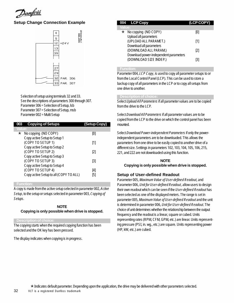
32 VLT is a registered Danfoss trademark
Setup Change Connection Example
Selection of setup using terminals 32 and 33.See the descriptions of parameters 300 through 307.Parameter 306 = Selection of Setup, lsbParameter 307 = Selection of Setup, msbParameter 002 = Multi Setup
003 Copying of Setups (Setup Copy)Value: No copying (NO COPY) [0]
Copy active Setup to Setup 1(COPY TO SETUP 1) [1]Copy active Setup to Setup 2(COPY TO SETUP 2) [2]Copy active Setup to Setup 3(COPY TO SETUP 3) [3]Copy active Setup to Setup 4(COPY TO SETUP 4) [4]Copy active Setup to all (COPY TO ALL) [5]
Function:A copy is made from the active setup selected in parameter 002, ActiveSetup, to the setup or setups selected in parameter 003, Copying ofSetups.
NOTECopying is only possible when drive is stopped.
Description of choice:The copying starts when the required copying function has beenselected and the OK key has been pressed.
The display indicates when copying is in progress.
004 LCP Copy (LCP COPY)Value: No copying (NO COPY) [0]
Upload all parameters(UPLOAD ALL PARAMET.) [1]Download all parameters(DOWNLOAD ALL PARAM.) [2]Download power-independent parameters(DOWNLOAD SIZE INDEP.) [3]
Function:Parameter 004, LCP Copy, is used to copy all parameter setups to orfrom the Local Control Panel (LCP). This can be used to store abackup copy of all parameters in the LCP or to copy all setups fromone drive to another.
Description of choice:Select Upload All Parameters if all parameter values are to be copiedfrom the drive to the LCP.
Select Download All Parameters if all parameter values are to becopied from the LCP to the drive on which the control panel has beenmounted.
Select Download Power-independent Parameters if only the power-independent parameters are to be downloaded. This allows theparameters from one drive to be easily copied to another drive of adifferent size. Settings in parameters 102, 103, 104, 105, 106, 215,221, and 222 are not downloaded using this function.
NOTECopying is only possible when drive is stopped.
Setup of User-defined ReadoutParameter 005, Maximum Value of User-defined Readout, andParameter 006, Unit for User-defined Readout, allow users to designtheir own readout which can be seen if the User-defined Readout hasbeen selected as one of the displayed meters. The range is set inparameter 005, Maximum Value of User-defined Readout and the unitis determined in parameter 006, Unit for User-defined Readout. Thechoice of unit determines whether the relationship between the outputfrequency and the readout is a linear, square or cubed. Unitsrepresenting rates (RPM, CFM, GPM, etc.) are linear. Units represent-ing pressure (PSI, in. wg., etc.) are square. Units representing power(HP, kW, etc.) are cubed.
Indicates default parameter. Depending upon the application, the drive may be delivered with other parameters selected.
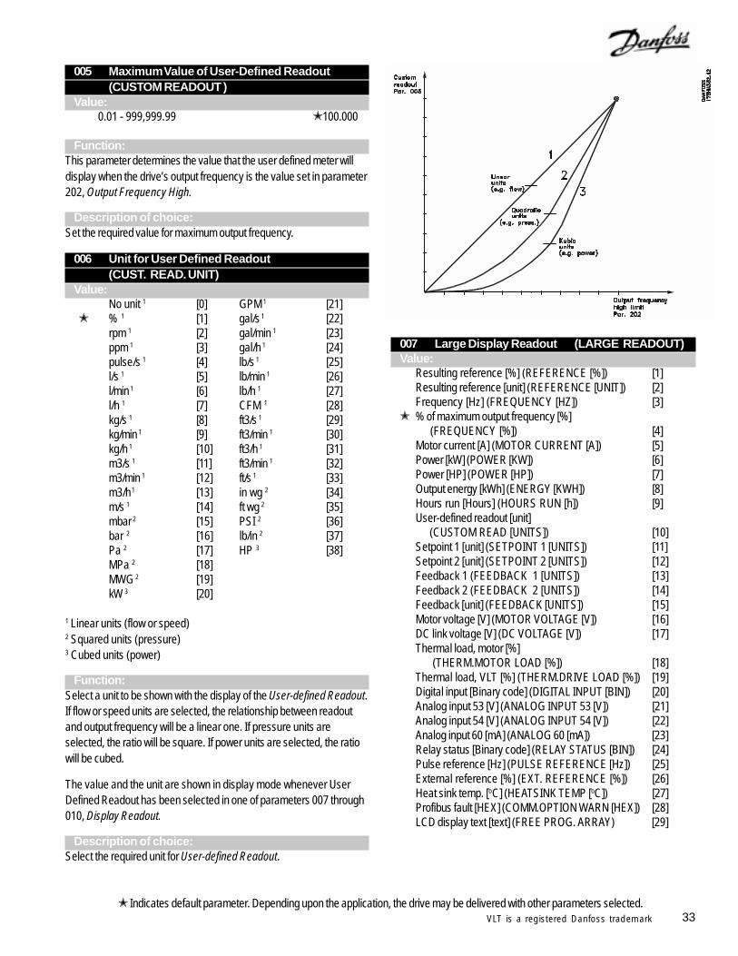
33VLT is a registered Danfoss trademark
005 Maximum Value of User-Defined Readout(CUSTOM READOUT )
Value:0.01 - 999,999.99 100.000
Function:This parameter determines the value that the user defined meter willdisplay when the drive’s output frequency is the value set in parameter202, Output Frequency High.
Description of choice:Set the required value for maximum output frequency.
006 Unit for User Defined Readout(CUST. READ. UNIT)
Value:No unit 1 [0] GPM 1 [21]
% 1 [1] gal/s 1 [22]rpm 1 [2] gal/min 1 [23]ppm 1 [3] gal/h 1 [24]pulse/s 1 [4] lb/s 1 [25]l/s 1 [5] lb/min 1 [26]l/min 1 [6] lb/h 1 [27]l/h 1 [7] CFM 1 [28]kg/s 1 [8] ft3/s 1 [29]kg/min 1 [9] ft3/min 1 [30]kg/h 1 [10] ft3/h 1 [31]m3/s 1 [11] ft3/min 1 [32]m3/min 1 [12] ft/s 1 [33]m3/h 1 [13] in wg 2 [34]m/s 1 [14] ft wg 2 [35]mbar 2 [15] PSI 2 [36]bar 2 [16] lb/in 2 [37]Pa 2 [17] HP 3 [38]MPa 2 [18]MWG 2 [19]kW 3 [20]
1 Linear units (flow or speed)2 Squared units (pressure)3 Cubed units (power)
Function:Select a unit to be shown with the display of the User-defined Readout.If flow or speed units are selected, the relationship between readoutand output frequency will be a linear one. If pressure units areselected, the ratio will be square. If power units are selected, the ratiowill be cubed.
The value and the unit are shown in display mode whenever UserDefined Readout has been selected in one of parameters 007 through010, Display Readout.
Description of choice:Select the required unit for User-defined Readout.
Indicates default parameter. Depending upon the application, the drive may be delivered with other parameters selected.
007 Large Display Readout (LARGE READOUT)Value:
Resulting reference [%] (REFERENCE [%]) [1]Resulting reference [unit] (REFERENCE [UNIT]) [2]Frequency [Hz] (FREQUENCY [HZ]) [3]
% of maximum output frequency [%] (FREQUENCY [%]) [4]Motor current [A] (MOTOR CURRENT [A]) [5]Power [kW] (POWER [KW]) [6]Power [HP] (POWER [HP]) [7]Output energy [kWh] (ENERGY [KWH]) [8]Hours run [Hours] (HOURS RUN [h]) [9]User-defined readout [unit] (CUSTOM READ [UNITS]) [10]Setpoint 1 [unit] (SETPOINT 1 [UNITS]) [11]Setpoint 2 [unit] (SETPOINT 2 [UNITS]) [12]Feedback 1 (FEEDBACK 1 [UNITS]) [13]Feedback 2 (FEEDBACK 2 [UNITS]) [14]Feedback [unit] (FEEDBACK [UNITS]) [15]Motor voltage [V] (MOTOR VOLTAGE [V]) [16]DC link voltage [V] (DC VOLTAGE [V]) [17]Thermal load, motor [%] (THERM.MOTOR LOAD [%]) [18]Thermal load, VLT [%] (THERM.DRIVE LOAD [%]) [19]Digital input [Binary code] (DIGITAL INPUT [BIN]) [20]Analog input 53 [V] (ANALOG INPUT 53 [V]) [21]Analog input 54 [V] (ANALOG INPUT 54 [V]) [22]Analog input 60 [mA] (ANALOG 60 [mA]) [23]Relay status [Binary code] (RELAY STATUS [BIN]) [24]Pulse reference [Hz] (PULSE REFERENCE [Hz]) [25]External reference [%] (EXT. REFERENCE [%]) [26]Heat sink temp. [oC] (HEATSINK TEMP [oC]) [27]Profibus fault [HEX] (COMM.OPTION WARN [HEX]) [28]LCD display text [text] (FREE PROG. ARRAY) [29]
34 VLT is a registered Danfoss trademark Indicates default parameter. Depending upon the application, the drive may be delivered with other parameters selected.
Function:This parameter allows a choice of the data value to be shown in thelarge display when power is applied to the drive. In Display ModeI, the+ and - keys change this display when the drive is in operation.
Description of choice:No readout can only be selected in parameters 008 through 010, SmallDisplay Readout, but not in parameter 007, Large Display Readout.
Resulting reference [%] gives the total of all references as apercentage of parameter 205, Maximum Reference.
Reference [unit] gives the total of all references. This is displayed inHz in open loop. In closed loop, the reference unit is selected inparameter 415, Process Units.
Frequency [Hz] gives the output frequency of the drive.
% of maximum output frequency [%] is the output frequency as apercentage of parameter 202, Output Frequency High Limit.
Motor current [A] is the average phase current of the motor.
Power [kW] is the actual power, in kW, delivered to the motor.
Power [HP] is the actual power, in HP, delivered to the motor.
Output energy [kWh] is the energy delivered by the motor since thelatest reset was made using parameter 618, Reset of kWh Counter.
Hours run [hours] is the number of hours that the motor has runsince the latest reset was made using parameter 619, Reset of HoursRun Counter.
User Defined readout [-] is a user defined value, calculated on thebasis of the present output frequency, as well as the scaling inparameter 005, Maximum Value of User-Defined Readout, and theunit in parameter 006, Unit for User-Defined Readout.
Setpoint 1 [unit] is the setpoint value programmed in parameter 418,Setpoint 1. The unit is selected in parameter 415, Process Units.
Setpoint 2 [unit] is the setpoint value programmed in parameter 419,Setpoint 2. The unit is selected in parameter 415, Process Units.
Feedback 1 [unit] is the value of the feedback signal applied toTerminal 53. The unit is selected in parameter 415, Process Units.
Feedback 2 [unit] is the value of the feedback signal applied toTerminal 54. The unit is selected in parameter 415, Process Units.
Feedback [unit] is the total feedback signal using the unit scalingselected in parameter 413, Minimum Feedback; parameter 414Maximum Feedback; parameter 415, Process Units; and parameter417, 2 Feedback Calc.
Motor voltage [V] is the voltage supplied to the motor.
DC link voltage [V] is the drive DC bus voltage.
Thermal load, motor [%] is the calculated thermal load of the motor.100% is the cutout limit. See also parameter 117, Motor ThermalProtection.
Thermal load, VLT [%] is the calculated thermal load of the drive.100% is the trip point.
Digital input [binary code] is the signal status from the 8 digitalinputs (16, 17, 18, 19, 27, 29, 32 and 33). Terminal 16 corresponds tothe bit at the far left. (0 = no signal, 1 = connected signal.)
Analog input 53 [V] is the voltage applied to terminal 53.
Analog input 54 [V] is the voltage applied to terminal 54.
Analog input 60 [mA] is the current applied to terminal 60.
Relay status [binary code] displays the open or closed position ofrelays 1 through 6 in binary code. Open is 0 and closed 1, read left toright (positions 7 and 8, displayed in parameter 007, are not used.)
Pulse reference [Hz] is the pulse frequency in Hz applied to terminal17 or terminal 29.
External reference [%] is the sum of the external references as apercentage of parameter 205, Maximum Reference.
Heat sink temp. [°C] is the present heat sink temperature of the drive.The trip point is 90 ± 5°C for NEMA 1 units, 80 ± 5°C for NEMA 12.
Profibus fault [HEX] is enabled when the Profibus protocol option isinstalled and corresponds to the warnings in Profibus parameter 953.
LCD display text [text] displays the text programmed in parameter533, Display Text 1, and 534, Display Text 2, through the serialcommunications port..
008 Small Display Readout 1.1(SMALL READOUT 1)
Value:See parameter 007, Large Display Readout
Reference, %
Function:This parameter selects the meter to be displayed on the left display online 1. Showing three different meters on line 1 is recommended whensetting up the PID. This allows tracking how the process reacts to achange of reference.
Description of choice:There is a choice of 26 different meters. See parameter 007, LargeDisplay Readout.
009 Small Display Readout 1.2(SMALL READOUT 2)
Value:See parameter 007, Large Display Readout
Motor current [A]
35VLT is a registered Danfoss trademark
Indicates default parameter. Depending upon the application, the drive may be delivered with other parameters selected.
Function:See the functional description for parameter 008, Small DisplayReadout.
Description of choice:There is a choice of 26 meters, see parameter 007 Large DisplayReadout.
010 Small Display Readout 1.3(SMALL READOUT 3)
Value:See parameter 007 Large Display Readout
Power [HP]
Function:See the functional description for parameter 008 Small Data Readout.
Description of choice:There is a choice of 26 different data values, see parameter 007 LargeDisplay Readout.
011 Unit of Local Reference (UNIT OF LOC REF)Value:
Hz (HZ) [0] % of output frequency range (%) (% OF FMAX) [1]
Function:This parameter sets the unit that will be displayed in Display Mode IVwhen the drive’s speed is being controlled locally.
Description of choice:Choose the desired unit for local reference.
012 Hand Start on LCP (HAND START BUTTON)Value:
Disable (DISABLE) [0] Enable (ENABLE) [1]
Function:This parameter allows disabling the Hand/Start key on the keypad.
Description of choice:If Disable is selected in this parameter, the Hand/Start key will bedisabled.
013 OFF/STOP on LCP (STOP BUTTON)Value:
Disable (DISABLE) [0] Enable (ENABLE) [1]
Function:This parameter allows disabling the Off/Stop key on the keypad.
Description of choice:If Disable is selected in this parameter, the Off/Stop key will be disabled.
If Disable is selected, motor cannot be stoppedby Off/Stop key.
014 Auto Start on LCP (AUTO START BTTN)Value
Disable (DISABLE) [0] Enable (ENABLE) [1]
Function:This parameter allows disabling the Auto/Start key on the keypad.
Description of choice:If Disable is selected in this parameter, the Auto/Start key will bedisabled.
P 015015 Reset on LCP (RESET BUTTON)Value:
Disable (DISABLE) [0] Enable (ENABLE) [1]
Function:This parameter allows disabling the Reset key on the keypad.
Description of choice:If Disable is selected in this parameter, the Reset key will be inactive.
Do not disable Reset unless a remote reset isavailable through digital inputs and parameters300 through 307.
016 Lock for Data Change (DATA CHANGE LOCK)Value: Not Locked (NOT LOCKED) [0]
Locked (LOCKED) [1]
Function:This parameter allows locking out parameter changes at the localcontrol panel.
Description of choice:If Locked is selected, data modifications in the parameters cannot bemade. Parameter changes will be possible through serial communica-tion.
Parameters 007 through 010, Display Readout can be changed at thelocal control panel.
The local control panel can also be locked or unlocked by a digitalinput controlled by parameters 300 through 307.
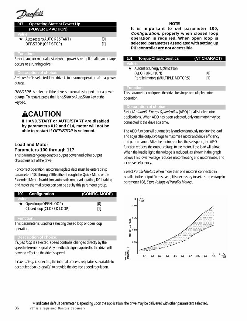
36 VLT is a registered Danfoss trademark Indicates default parameter. Depending upon the application, the drive may be delivered with other parameters selected.
017 Operating State at Power Up(POWER UP ACTION)
Value: Auto restart (AUTO RESTART) [0]
OFF/STOP (OFF/STOP) [1]
Function:Selects auto or manual restart when power is reapplied after an outageoccurs to a running drive.
Description of choice:Auto restart is selected if the drive is to resume operation after a poweroutage.
OFF/STOP is selected if the drive is to remain stopped after a poweroutage. To restart, press the Hand/Start or Auto/Start key at thekeypad.
If HAND/START or AUTO/START are disabledby parameters 012 and 014, motor will not beable to restart if OFF/STOP is selected.
Load and MotorParameters 100 through 117This parameter group controls output power and other outputcharacteristics of the drive.
For correct operation, motor nameplate data must be entered intoparameters 102 through 106 either through the Quick Menu or theExtended Menu. In addition, automatic motor adaptation, DC brakingand motor thermal protection can be set by this parameter group.
100 Configuration (CONFIG. MODE)Value: Open loop (OPEN LOOP) [0]
Closed loop (CLOSED LOOP) [1]
Function:This parameter is used for selecting closed loop or open loopoperation.
Description of choice:If Open loop is selected, speed control is changed directly by thespeed reference signal. Any feedback signal applied to the drive willhave no effect on the drive’s speed.
If Closed loop is selected, the internal process regulator is available toaccept feedback signal(s) to provide the desired speed regulation.
NOTEIt is important to set parameter 100,Configuration, properly when closed loopoperation is required. When open loop isselected, parameters associated with setting upPID controller are not accessible.
Characteristics101 Torque Characteristics ( VT CHARACT)Value: Automatic Energy Optimization
(AEO FUNCTION) [0]Parallel motors (MULTIPLE MOTORS) [1]
Function:This parameter configures the drive for single or multiple motoroperation.
Description of choice:Select Automatic Energy Optimization (AEO) for all single motorapplications. When AEO has been selected, only one motor may beconnected to the drive at a time.
The AEO function will automatically and continuously monitor the loadand adjust the output voltage to maximize motor and drive efficiencyand performance. After the motor reaches the set speed, the AEOfunction reduces the output voltage to the motor, if the load will allow.When the load is light, the voltage is reduced, as shown in the graphbelow. This lower voltage reduces motor heating and motor noise, andincreases efficiency.
Select Parallel motors when more than one motor is connected inparallel to the output. In this case, it is necessary to set a start voltage inparameter 108, Start Voltage of Parallel Motors.
37VLT is a registered Danfoss trademark
Indicates default parameter. Depending upon the application, the drive may be delivered with other parameters selected.
It is very important that values set in param-eters 102, Motor Power, through 106, Rated MotorSpeed, correspond accurately to nameplate dataof motor.
102 Motor Power (MOTOR POWER)Value:
0.25 kW (0.33 HP) [25]0.37 kW (0.5 HP) [37]0.55 kW (0.75 HP) [55]0.75 kW (1 HP) [75]1.1 kW (1.5 HP) [110]1.5 kW (2 HP) [150]2.2 kW (3 HP) [220]3 kW -- [300]4 kW (5 HP) [400]5.5 kW (7.5 HP) [550]7.5 kW (10 HP) [750]11 kW (15 HP) [1100]15 kW (20 HP) [1500]18.5 kW (25 HP) [1850]22 kW (30 HP) [2200]30 kW (40 HP) [3000]37 kW (50 HP) [3700]45 kW (60 HP) [4500]55 kW (75 HP) [5500]75 kW (100 HP) [7500]90 kW (125 HP) [9000]110 kW (150 HP) [11000]132 kW (175 HP) [13200]160 kW (200 HP) [16000]200 kW (300 HP) [20000]250 kW -- [25000]300 kW -- [30000]315 kW (350 HP) [31500]355 kW (450 HP) [35500]400 kW (500 HP) [40000]450 kW (600 HP) [50000] Depends on the unit
Function:Set the power value that corresponds to the nameplate power of themotor. The default setting is the full rating of the drive.
Description of choice:Select a value that equals the nameplate data on the motor. It is alsopossible to set any power within the range of the drive.
103 Motor Voltage (MOTOR VOLTAGE)Value:
200 V [200]208 V [208]220 V [220]230 V [230]240 V [240]380 V [380]400 V [400]415 V [415]440 V [440]460 V [460]480 V [480]500 V [500]575 V [575]
Depends on the unitFunction:
Set the rated motor voltage.
Description of choice:Select a value that equals the nameplate data on the motor. This maybe less than the input voltage. It is also possible to set any voltagewithin the range of the drive.
104 Motor Frequency (MOTOR FREQUENCY)Value:
50 Hz (50 Hz) [50] 60 Hz (60 Hz) [60]
Function:This is where the rated motor frequency is selected. This is usually thefrequency of the power line.
Description of choice:Select the desired value. It is also possible to set any frequency withinthe range of the drive.
Enter correct value in parameter 105, Motor Cur-rent, since this forms part of VVC+ control.Changing values in parameter 102, Motor Power,or parameter 103, Motor Voltage, after motorcurrent has been entered in parameter 105, mayautomatically change the value in parameter 105.
105 Motor Current (MOTOR CURRENT)Value:0.01 to drive rating
Set based on motor nameplate.
Function:The rated motor current in amps is used for setting output current andproviding motor thermal protection. It is important to set the motorcurrent to the full load current rating (FLA) of the motor.
Description of choice:Set a value that equals the nameplate data on the motor.
38 VLT is a registered Danfoss trademark Indicates default parameter. Depending upon the application, the drive may be delivered with other parameters selected.
Enter correct value in parameter 106, RatedMotor Speed, since this forms part of VVC+
control feature. Changing value in parameter104, Motor Frequency, after rated motor speedhas been entered in parameter 106, mayautomatically change the value in parameter 106.
106 Rated Motor Speed (MOTOR NOM. SPEED)Value:
100 through 60000 Depends on parameter 102, Motor Power
Function:This is where the value is set that corresponds to the rated motorspeed shown on the motor nameplate.
Description of choice:Choose a value that corresponds to the motor nameplate data.
107 Automatic Motor Adaptation, AMA(AUTO MOTOR ADAPT)
Value: Optimization disable (NO AMA) [0]
Automatic adaptation (RUN AMA) [1]Limited AMA (RUN LIMITED AMA) [2]
Function:Automatic Motor Adaptation (AMA) is an advanced procedure thatmeasures electrical characteristics of the motor. This procedure doesnot cause the motor to run.
AMA optimizes the adjustment of the drive to the motor. This feature isparticularly useful when the drive-to-motor cable length is long, andwith nonstandard motors or high HP motors. Although it is notnecessary to run AMA, it is highly recommended for optimum operationand increases the capability of the Automatic Energy Optimizationfunction selectable in parameter 101, Torque Characteristics.
For the best adjustment of the drive, it is recommended to carry outAMA on a cold motor.
Repeated AMA operation may lead to a heatingof motor that will result in an increase of statorresistance. This will reduce accuracy. Allowmotor to cool before running AMA.
If an output LC-filter has been connected between the drive and themotor, select Limited AMA. If the complete AMA procedure is desired,remove the LC-filter, run Automatic Adaptation (RUN AMA), andreinstall the filter.
NOTESome motors (such as motors with 6 or morepoles) may be unable to run AutomaticAdaptation. Limited AMA is a procedure whichcan be effective in such cases since resultsmeasure motor’s stator and effects of cablelength. Multiple motor applications cannot useAMA.
The following must be noted when either AMA function is used:
- Before running AMA, the correct nameplate data for the motormust be entered in parameters 102 through 106.
- Total automatic motor adaptation may take up to 10 minutes.- Alarms and warnings will be shown in the display if faults occur
during motor adaptation.- AMA can only be carried out if the rated motor current of the motor
is at least 35% of the rated output current of the drive.
Description of choice:Select Automatic Adaptation if the drive is to carry out a completeautomatic motor adaptation procedure.
Select Limited AMA if an LC-filter has been placed between the driveand the motor, for a motor with 6 or more poles, or if AutomaticAdaptation was unsuccessful. Some drives may display AutomaticAdaptation with LC-filter rather than Limited AMA. The functions arethe same.
Procedure for Automatic Motor Adaptation:1. Set motor parameters 102 through 106 according to motor
nameplate data.2. Connect 24 VDC from terminal 12, or from external source, to
terminal 27.3. Select either Automatic Adaptation or Limited AMA in parameter
107, Automatic Motor Adaptation.4. Start drive by pressing Hand Start or connect terminal 18 (start) to
terminal 12 and press Auto Start.To stop automatic adaptation or limited AMA prior to completion:
Press OFF/STOP key.After a normal sequence is complete, the display reads: AMA STOP
Press RESET key. Drive is now ready for operation.
NOTERESET key must be pressed after AMAis completed to save results to drive.
If there is a fault, the display reads: ALARM 221. Check alarms section in this manual for possible causes of alarm.2. Press RESET key to clear fault.
If there is a warning, the display reads: WARNING (39 through 42)1. Check warnings section in this manual for possible causes of
warning.2. Press CHANGE DATA key and select Continue if AMA is to
continue despite warning, or press OFF/STOP key to stop AMA.
39VLT is a registered Danfoss trademark
108 Start Voltage of Parallel Motors(MULTIM.START VOLT)
Value:0.0 through parameter 103 Motor Voltage depends on par. 103 Motor Voltage
Function:This parameter sets the voltage at 0 Hz for all drives with two or moremotors connected in parallel.
The start voltage represents a supplementary voltage input to themotor. Increasing the start voltage will increase the starting torque. Astart voltage is especially useful for small motors (<5 HP) as they havea higher stator resistance than larger motors.
This function is only active if Parallel Motors has been selected inparameter 101, Torque Characteristics.
Description of choice:To set the start voltage, monitor the motor current while starting the loadand choose the starting voltage that gives the lowest starting current.Start with a small value and increase only as required for reliablestarting.
109 Resonance Dampening (RESONANCE DAMP.)Value:0 to 500 % 100 %
Function:High-frequency resonances in the motor can be eliminated by adjustingthis parameter.
Description of choice:Adjust the dampening percentage for smoothest high speed operation.
110 High Breakaway Torque (HIGH START TORQ.)Value:0.0 to 0.5 sec. OFF
Function:The drive is able to breakaway high friction loads. This high startingtorque, approximately 1.6 x rated torque is available for up to 0.5seconds. The current level is limited by the protective circuits of thedrive. OFF corresponds to 0.0 sec.
Description of choice:Set the time for which high starting torque is desired.
111 Start Delay (START DELAY)Value:0.0 to 120.0 sec. 0.0 sec.
Function:This parameter allows a delayed start of the drive after the conditionsfor start have been fulfilled. After the start delay time has elapsed, thedrive will start and ramp up to the commanded speed.
Description of choice:Set the desired time before the drive will start.
112 Motor Preheat (MOTOR PREHEAT)Value: Disable (DISABLE) [0]
Enable (ENABLE) [1]
Function:The motor preheat function protects the motor from condensation byrunning a small DC current through the motor. Motor preheat is onlyactive during stop when control voltage is applied to terminal 27.
Description of choice:Select Disable if this function is not required. Select Enable to activate motorpreheating. The amount of motor preheating is set in parameter 113.
Be sure to check parameter 113 if parameter112, Motor Preheat, is enabled. Excessive currentor preheating time may damage motor. Do notapply any more current than required.
113 Motor Preheat DC Current(PREHEAT DC-CURR.)
Value:0 to 100 % 50 %
The maximum value depends on the rated motor current.
Function:The motor can be preheated when stopped by applying DC current toit. A holding torque can also be provided.
Description of choice:The motor can be preheated by means of a DC current. At 0%, thefunction is inactive; at a value higher than 0%, a DC current will besupplied to the motor whenever it is stopped. A windmilling fan can beheld by providing a holding toque by using this parameter.
Indicates default parameter. Depending upon the application, the drive may be delivered with other parameters selected.
40 VLT is a registered Danfoss trademark
DC BrakingApplying DC current to the motor will brake the motor. Parameter 114,DC Braking Current, sets the DC braking current as a percentage ofthe rated motor current. Parameter 115, DC Braking Time, sets theamount of time that the DC current will be applied. Parameter 116, DCBrake Cut-in Frequency, sets the frequency at which DC brakingbegins when the motor decelerates during a stop.
If terminal 19 or 27 (parameters 303 or 304 Digital Input) has beenprogrammed to DC Braking Inverse and shifts from logic ‘1’ to logic ‘0’,the DC braking will be activated immediately.
When the start signal on terminal 18 changes from logic ‘1’ to logic ‘0’,the DC braking will be activated when the output frequency becomeslower than the brake cut-in frequency.
If a DC brake current is set in parameter 114, the drive’s switchingfrequency will be limited to 4 kHz during the braking.
A high braking current supplied for a long timewill overheat motor. Use only the DC brakingcurrent and time required.
Do not use DC braking function if inertia ofdriven load is more than 20 times inertia ofmotor.
114 DC Braking Current (DC BRAKE CURRENT)Value:
0 to 100% 50 %The maximum value depends on the rated motor current.
Function:This parameter is used for setting the DC braking current that isapplied:
1. When the DC brake frequency set in parameter 116 DC BrakeCut-in Frequency has been reached during a stop.
2. When DC brake inverse is active via terminal 19 or 27, or via theserial bus.
The DC braking current will be active for the duration of the DCbraking time set in parameter 115 DC Braking Time.
Description of choice:To be set as a percentage value of the rated motor current set inparameter 105 Motor Current.
100% DC braking current corresponds to the value set in parameter105.
Most HVAC applications do not required brakingor holding. It is suggested that parameter 114remain set at 0 unless braking or holding torqueis required.
115 DC Braking Time (DC BRAKE TIME)Value:0.0 to 60.0 sec. 10.0 sec.
Function:This parameter sets the time that the DC braking is active.
Description of choice:Set the desired time.
116 DC Brake Cut-in Frequency(DC BRAKE CUT-IN)
Value:0.0 (OFF) to setting of parameter 202 OFF
Function:This parameter is used for setting the frequency at which DC brakingbegins after a stop command is issued.
Description of choice:Set the desired frequency for braking to begin upon deceleration.
Indicates default parameter. Depending upon the application, the drive may be delivered with other parameters selected.
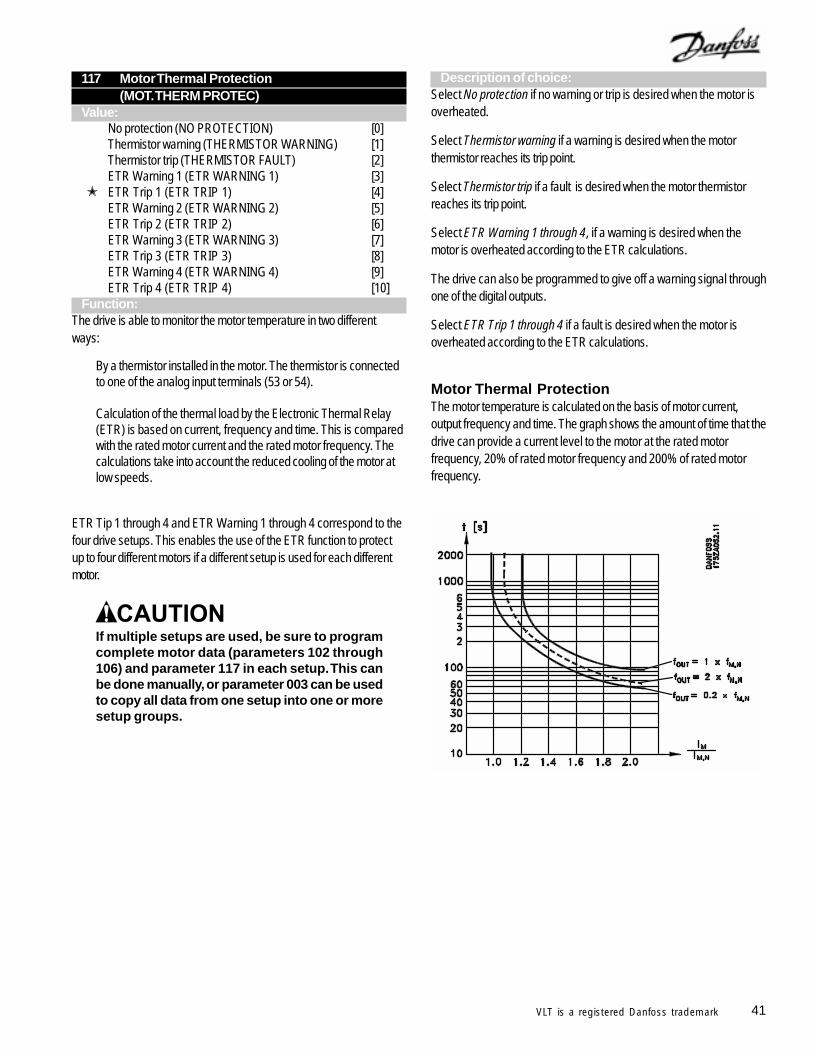
41VLT is a registered Danfoss trademark
117 Motor Thermal Protection(MOT. THERM PROTEC)
Value:No protection (NO PROTECTION) [0]Thermistor warning (THERMISTOR WARNING) [1]Thermistor trip (THERMISTOR FAULT) [2]ETR Warning 1 (ETR WARNING 1) [3]
ETR Trip 1 (ETR TRIP 1) [4]ETR Warning 2 (ETR WARNING 2) [5]ETR Trip 2 (ETR TRIP 2) [6]ETR Warning 3 (ETR WARNING 3) [7]ETR Trip 3 (ETR TRIP 3) [8]ETR Warning 4 (ETR WARNING 4) [9]ETR Trip 4 (ETR TRIP 4) [10]
Function:The drive is able to monitor the motor temperature in two differentways:
By a thermistor installed in the motor. The thermistor is connectedto one of the analog input terminals (53 or 54).
Calculation of the thermal load by the Electronic Thermal Relay(ETR) is based on current, frequency and time. This is comparedwith the rated motor current and the rated motor frequency. Thecalculations take into account the reduced cooling of the motor atlow speeds.
ETR Tip 1 through 4 and ETR Warning 1 through 4 correspond to thefour drive setups. This enables the use of the ETR function to protectup to four different motors if a different setup is used for each differentmotor.
If multiple setups are used, be sure to programcomplete motor data (parameters 102 through106) and parameter 117 in each setup. This canbe done manually, or parameter 003 can be usedto copy all data from one setup into one or moresetup groups.
Motor Thermal ProtectionThe motor temperature is calculated on the basis of motor current,output frequency and time. The graph shows the amount of time that thedrive can provide a current level to the motor at the rated motorfrequency, 20% of rated motor frequency and 200% of rated motorfrequency.
Description of choice:Select No protection if no warning or trip is desired when the motor isoverheated.
Select Thermistor warning if a warning is desired when the motorthermistor reaches its trip point.
Select Thermistor trip if a fault is desired when the motor thermistorreaches its trip point.
Select ETR Warning 1 through 4, if a warning is desired when themotor is overheated according to the ETR calculations.
The drive can also be programmed to give off a warning signal throughone of the digital outputs.
Select ETR Trip 1 through 4 if a fault is desired when the motor isoverheated according to the ETR calculations.
42 VLT is a registered Danfoss trademark Indicates default parameter. Depending upon the application, the drive may be delivered with other parameters selected.
References and LimitsParameters 200 through 228In this parameter group, the frequencies and references of the driveare set.
This parameter group includes:
- Setting of ramp times- Choice of four preset references- Setting four bypass frequencies- Setting maximum current to motor- Setting warning limits for current, frequency, reference and
feedback
200 Output Frequency Range(FREQUENCY RANGE)
Value:
0 to 120 Hz (0 - 120 HZ) [0]
0 to 1000 Hz (0 - 1000 HZ) [1]
Function:Choose one of two maximum output frequency ranges.
Description of choice:Select the output frequency range that includes the highest outputfrequency required for normal operation.
HVAC applications seldom require outputfrequency greater than 120 Hz. Check withDanfoss Graham, manufacturer of motor, ormanufacturer of driven equipment beforeselecting 0 - 1000 Hz range.
201 Output Frequency Low Limit(MIN. FREQUENCY)
Value: 0.0 to parameter 202 0.0 HZ
Function:Set the minimum speed at which the motor is to run.
Description of choice:A value from 0.0 Hz to the Output Frequency High Limit
frequency set
in parameter 202 can be selected. The drive will not be able to runcontinuously at an output frequency below this value in any mode.
202 Output Frequency High Limit(MAX. FREQUENCY)
Value:Parameter 201 to parameter 200 60 Hz
Function:Set the highest speed at which the motor is to run.
NOTEOutput frequency of drive can never assumevalue higher than 1/10th of switching frequency.See parameter 407, Switching Frequency.
Description of choice:Set a value between the low frequency limit, set in parameter 201, andthe frequency range limit, set in parameter 200. The drive will not beable to run continuously at an output frequency above this value in anymode.
HVAC applications seldom require output fre-quency greater than 60 Hz. Check with DanfossGraham, manufacturer of motor, and manufac-turer of driven equipment before selectingmaximum frequency greater than 60 Hz.
NOTEFor fan applications, factory setting of param-eter 201 is 6 Hz. For pump applications, factorysetting for parameter 201 is 18 Hz.
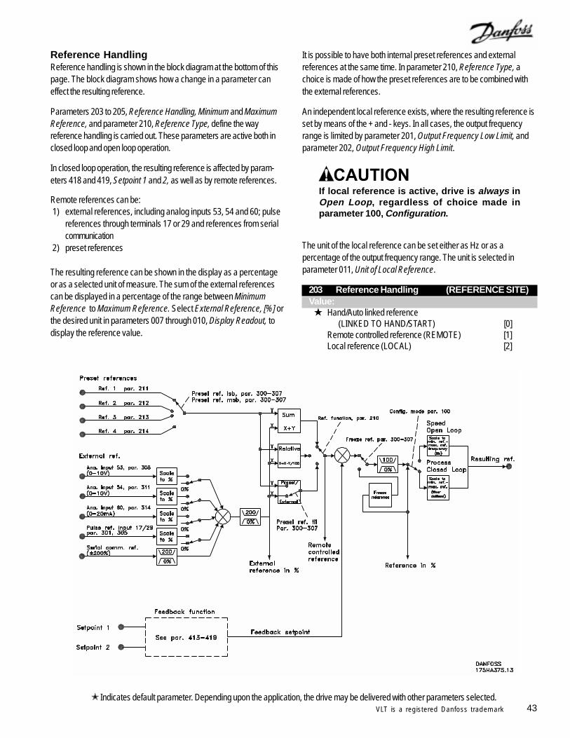
43VLT is a registered Danfoss trademark
Reference HandlingReference handling is shown in the block diagram at the bottom of thispage. The block diagram shows how a change in a parameter caneffect the resulting reference.
Parameters 203 to 205, Reference Handling, Minimum and MaximumReference, and parameter 210, Reference Type, define the wayreference handling is carried out. These parameters are active both inclosed loop and open loop operation.
In closed loop operation, the resulting reference is affected by param-eters 418 and 419, Setpoint 1 and 2, as well as by remote references.
Remote references can be:1) external references, including analog inputs 53, 54 and 60; pulse
references through terminals 17 or 29 and references from serialcommunication
2) preset references
The resulting reference can be shown in the display as a percentageor as a selected unit of measure. The sum of the external referencescan be displayed in a percentage of the range between MinimumReference to Maximum Reference. Select External Reference, [%] orthe desired unit in parameters 007 through 010, Display Readout, todisplay the reference value.
It is possible to have both internal preset references and externalreferences at the same time. In parameter 210, Reference Type, achoice is made of how the preset references are to be combined withthe external references.
An independent local reference exists, where the resulting reference isset by means of the + and - keys. In all cases, the output frequencyrange is limited by parameter 201, Output Frequency Low Limit, andparameter 202, Output Frequency High Limit.
If local reference is active, drive is always inOpen Loop, regardless of choice made inparameter 100, Configuration.
The unit of the local reference can be set either as Hz or as apercentage of the output frequency range. The unit is selected inparameter 011, Unit of Local Reference.
203 Reference Handling (REFERENCE SITE)Value:
Hand/Auto linked reference
(LINKED TO HAND/START) [0]Remote controlled reference (REMOTE) [1]Local reference (LOCAL) [2]
Indicates default parameter. Depending upon the application, the drive may be delivered with other parameters selected.
44 VLT is a registered Danfoss trademark
Function:This parameter chooses the active resulting reference. If Hand/Autolinked reference is selected, the resulting reference will depend onwhether the drive is in Hand or Auto mode.
The table below shows which reference is active when Hand/Autolinked reference, Remote reference or Local reference has beenselected. The Hand mode or Auto mode can be selected via thekeypad or by a digital input set in parameters 300 through 307 DigitalInputs.
Reference Handling Hand Mode Auto Mode Hand/Auto Local ref. active Remote ref. active Remote Remote ref. active Remote ref. active Local Local ref. active Local ref. active
Description of choice:If Hand/Auto linked reference is chosen, the motor speed in Handmode will be set by the local reference, while in Auto mode it is set bythe remote references and any setpoints selected.
If Remote reference is selected, the motor speed will depend onremote references and any setpoints selected, regardless of whetherHand mode or Auto mode has been chosen.
If Local reference is selected, the motor speed will only depend on thelocal reference set via the control panel, regardless of whether Handmode or Auto mode has been selected.
204 Minimum Reference (MIN. REFERENCE)Value:
If parameter 100, Configuration = Open loop,0.000Hz to parameter 205, Maximum Reference. 0.000 Hz
If parameter 100 Configuration = Closed loop,parameter 413, Minimum Feedback, toparameter 205, Maximum Reference. 0.000 Hz
Function:The Minimum Reference sets the minimum value of the sum of allreferences. If Closed loop has been selected in parameter 100,Configuration, the minimum reference is limited by parameter 413,Minimum Feedback.
Minimum reference is ignored when the local reference is active. In thiscase, minimum reference is determined by parameter 201, MinimumFrequency.
NOTEFor fan applications, factory setting of param-eter 204 is 6 Hz. For pump applications, factorysetting for parameter 204 is 18 Hz.
The unit for the reference can be seen from the following table:
UnitParameter 100 Configuration = Open loop HzParameter 100 Configuration = Closed loop Par. 415
Description of choice:Minimum Reference is the lowest reference value that can be set forthe drive.
205 Maximum Reference (MAX. REFERENCE)Value:If parameter 100, Configuration = Open loop,parameter 204, Minimum Reference, to 1000.000 Hz 60.000 Hz
If parameter 100, Configuration = Closed loop,parameter 204, Minimum Reference, toparameter 414, Maximum Feedback. 60.000 Hz
Function:The Maximum Reference sets the maximum value of the sum of allreferences. If Closed loop has been selected in parameter 100,Configuration, the maximum reference cannot be set above parameter414, Maximum Feedback. The Maximum Reference is ignored whenthe local reference is active.
The reference unit can be determined from the following table:
UnitParameter 100 Configuration = Open loop HzParameter 100 Configuration = Closed loop Par. 415
Description of choice:Maximum reference is the highest reference value that can be set forthe drive.
Indicates default parameter. Depending upon the application, the drive may be delivered with other parameters selected.
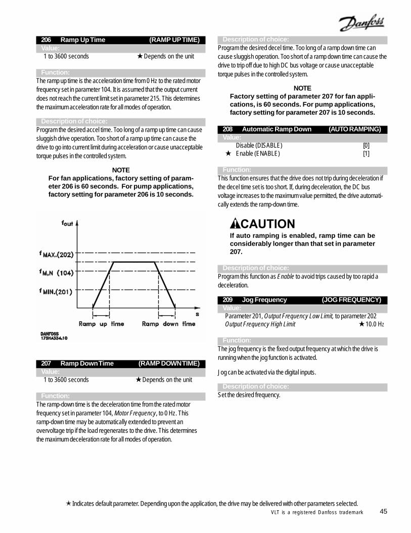
45VLT is a registered Danfoss trademark
206 Ramp Up Time (RAMP UP TIME)Value:1 to 3600 seconds Depends on the unit
Function:The ramp up time is the acceleration time from 0 Hz to the rated motorfrequency set in parameter 104. It is assumed that the output currentdoes not reach the current limit set in parameter 215. This determinesthe maximum acceleration rate for all modes of operation.
Description of choice:Program the desired accel time. Too long of a ramp up time can causesluggish drive operation. Too short of a ramp up time can cause thedrive to go into current limit during acceleration or cause unacceptabletorque pulses in the controlled system.
NOTEFor fan applications, factory setting of param-eter 206 is 60 seconds. For pump applications,factory setting for parameter 206 is 10 seconds.
207 Ramp Down Time (RAMP DOWN TIME)Value:1 to 3600 seconds Depends on the unit
Function:The ramp-down time is the deceleration time from the rated motorfrequency set in parameter 104, Motor Frequency, to 0 Hz. Thisramp-down time may be automatically extended to prevent anovervoltage trip if the load regenerates to the drive. This determinesthe maximum deceleration rate for all modes of operation.
Description of choice:Program the desired decel time. Too long of a ramp down time cancause sluggish operation. Too short of a ramp down time can cause thedrive to trip off due to high DC bus voltage or cause unacceptabletorque pulses in the controlled system.
NOTEFactory setting of parameter 207 for fan appli-cations, is 60 seconds. For pump applications,factory setting for parameter 207 is 10 seconds.
208 Automatic Ramp Down (AUTO RAMPING)Value:
Disable (DISABLE) [0] Enable (ENABLE) [1]
Function:This function ensures that the drive does not trip during deceleration ifthe decel time set is too short. If, during deceleration, the DC busvoltage increases to the maximum value permitted, the drive automati-cally extends the ramp-down time.
If auto ramping is enabled, ramp time can beconsiderably longer than that set in parameter207.
Description of choice:Program this function as Enable to avoid trips caused by too rapid adeceleration.
209 Jog Frequency (JOG FREQUENCY)Value:Parameter 201, Output Frequency Low Limit, to parameter 202Output Frequency High Limit 10.0 HZ
Function:The jog frequency is the fixed output frequency at which the drive isrunning when the jog function is activated.
Jog can be activated via the digital inputs.
Description of choice:Set the desired frequency.
Indicates default parameter. Depending upon the application, the drive may be delivered with other parameters selected.
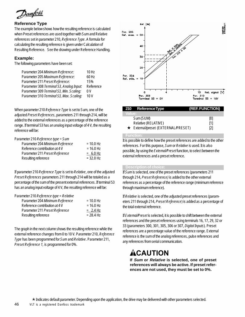
46 VLT is a registered Danfoss trademark
210 Reference Type (REF. FUNCTION)Value:
Sum (SUM) [0]Relative (RELATIVE) [1]
External/preset (EXTERNAL/PRESET) [2]
Function:It is possible to define how the preset references are added to the otherreferences. For this purpose, Sum or Relative is used. It is alsopossible, by using the External/Preset function, to select between theexternal references and a preset reference.
Description of choice:If Sum is selected, one of the preset references (parameters 211through 214, Preset Reference) is added to the other externalreferences as a percentage of the reference range (minimum referencethrough maximum reference).
If Relative is selected, one of the adjusted preset references (param-eters 211 through 214, Preset Reference) is added as a percentage ofthe total external reference.
If External/Preset is selected, it is possible to shift between the externalreferences and the preset references using terminals 16, 17, 29, 32 or33 (parameters 300, 301, 305, 306 or 307, Digital Inputs). Presetreferences are a percentage value of the reference range. Externalreference is the sum of the analog references, pulse references andany references from serial communication.
If Sum or Relative is selected, one of presetreferences will always be active. If preset refer-ences are not used, they must be set to 0%.
Reference TypeThe example below shows how the resulting reference is calculatedwhen Preset references are used together with Sum and Relativereferences set in parameter 210, Reference Type. A formula forcalculating the resulting reference is given under Calculation ofResulting Reference. See the drawing under Reference Handling.
Example:The following parameters have been set:
Parameter 204 Minimum Reference: 10 HzParameter 205 Maximum Reference: 60 HzParameter 211 Preset Reference: 15%Parameter 308 Terminal 53, Analog Input: ReferenceParameter 309 Terminal 53, Min. Scaling: 0 VParameter 310 Terminal 53, Max. Scaling: 10 V
When parameter 210 Reference Type is set to Sum, one of theadjusted Preset References, parameters 211 through 214, will beadded to the external references as a percentage of the referencerange. If terminal 53 has an analog input voltage of 4 V, the resultingreference will be:
Parameter 210 Reference type = SumParameter 204 Minimum Reference = 10.0 HzReference contribution at 4 V = 16.0 HzParameter 211 Preset Reference = 6.0 HzResulting reference = 32.0 Hz
If parameter 210 Reference Type is set to Relative, one of the adjustedPreset References parameters 211 through 214 will be totaled as apercentage of the sum of the present external references. If terminal 53has an analog input voltage of 4 V, the resulting reference will be:
Parameter 210 Reference type = RelativeParameter 204 Minimum Reference = 10.0 HzReference contribution at 4 V = 16.0 HzParameter 211 Preset Reference = 2.4 HzResulting reference = 28.4 Hz
The graph in the next column shows the resulting reference while theexternal reference changes from 0 to 10 V. Parameter 210, ReferenceType has been programmed for Sum and Relative. Parameter 211,Preset Reference 1, is programmed for 0%.
Indicates default parameter. Depending upon the application, the drive may be delivered with other parameters selected.
47VLT is a registered Danfoss trademark
211 Preset Reference 1 (PRESET REF. 1)212 Preset Reference 2 (PRESET REF. 2)213 Preset Reference 3 (PRESET REF. 3)214 Preset Reference 4 (PRESET REF. 4)Value:-100.00 % to +100.00 % 0.00% of the reference range or external reference
Function:Four different preset references can be programmed in parameters 211to 214, Preset Reference. The preset reference is stated as apercentage of the reference range or as a percentage of the otherexternal references, depending upon the choice made in parameter210, Reference Type.
The choice of preset references is made by activating terminals 16, 17,29, 32 or 33, as shown in the table below.
Terminal 17/29/33 Terminal 16/29/32 preset reference msb preset reference lsb
0 0 Preset reference 1 0 1 Preset reference 2 1 0 Preset reference 3 1 1 Preset reference 4
Description of choice:Set the required preset reference(s) that is/are to be used.
215 Current Limit (CURRENT LIMIT)Value:0.1 to 1.1 x rated current 1.1 x rated current
Function:This is where the maximum output current is set. If the motor attempts todraw more than this amount of current, the drive will reduce its outputfrequency until the current is less than or equal to the current limitvalue.
The factory setting corresponds to the rated output current. If thecurrent limit is to be used as motor protection, the rated motor currentmust be set. If the current limit is set within the range of 1.0 to 1.1 timesthe rated output current of the drive, the drive can only handle currentgreater than its rated output intermittently. After the load has beenhigher than rated output current limit, it must be reduced to a level that islower than the rated current of the drive for a period of time.
Note that if the current limit is set to less than the maximum value of thedrive, acceleration torque is reduced correspondingly.
Description of choice:Set the required maximum output current.
216 Frequency Bypass, Bandwidth(FREQUENCY BYPASS B.W.)
Value:0 (OFF) to 100 Hz DISABLED
Function:Mechanical resonance in the driven system sometimes makes itdesirable to avoid operation at critical speeds.
These output frequencies can be programmed in parameters 217through 220.
In this parameter, Frequency Bypass, Bandwidth, the width of thefrequency to be bypassed is defined.
Description of choice:The bypass bandwidth is equal to the programmed bandwidthfrequency. This bandwidth will be centered around each bypassfrequency.
217 Frequency Bypass 1 (BYPASS FREQ. 1)218 Frequency Bypass 2 (BYPASS FREQ. 2)219 Frequency Bypass 3 (BYPASS FREQ. 3)220 Frequency Bypass 4 (BYPASS FREQ. 4)Value:0 to 120 or 1000 HZ 120.0 Hz
The frequency range depends on the selection made in parameter200, Output Frequency Range.
Function:Some systems require that some output frequencies be avoidedbecause of mechanical resonance problems in the system.
Description of choice:Enter the frequencies to be avoided.
See also parameter 216, Frequency Bypass, Bandwidth.
Indicates default parameter. Depending upon the application, the drive may be delivered with other parameters selected.
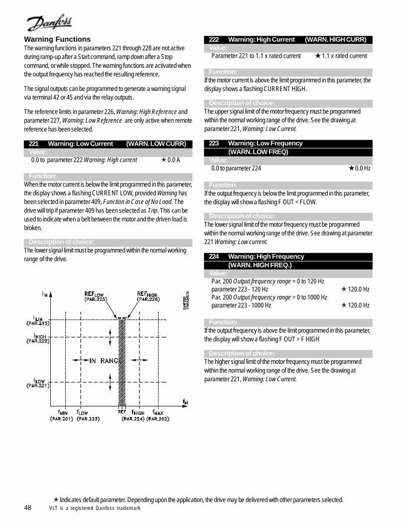
48 VLT is a registered Danfoss trademark
Warning FunctionsThe warning functions in parameters 221 through 228 are not activeduring ramp-up after a Start command, ramp down after a Stopcommand, or while stopped. The warning functions are activated whenthe output frequency has reached the resulting reference.
The signal outputs can be programmed to generate a warning signalvia terminal 42 or 45 and via the relay outputs.
The reference limits in parameter 226, Warning: High Reference andparameter 227, Warning: Low Reference are only active when remotereference has been selected.
221 Warning: Low Current (WARN. LOW CURR)Value:0.0 to parameter 222 Warning: High current 0.0 A
Function:When the motor current is below the limit programmed in this parameter,the display shows a flashing CURRENT LOW, provided Warning hasbeen selected in parameter 409, Function in Case of No Load. Thedrive will trip if parameter 409 has been selected as Trip. This can beused to indicate when a belt between the motor and the driven load isbroken.
Description of choice:The lower signal limit must be programmed within the normal workingrange of the drive.
222 Warning: High Current (WARN. HIGH CURR)Value:Parameter 221 to 1.1 x rated current 1.1 x rated current
Function:If the motor current is above the limit programmed in this parameter, thedisplay shows a flashing CURRENT HIGH.
Description of choice:The upper signal limit of the motor frequency must be programmedwithin the normal working range of the drive. See the drawing atparameter 221, Warning: Low Current.
223 Warning: Low Frequency(WARN. LOW FREQ)
Value:0.0 to parameter 224 0.0 Hz
Function:If the output frequency is below the limit programmed in this parameter,the display will show a flashing F OUT < FLOW.
Description of choice:The lower signal limit of the motor frequency must be programmedwithin the normal working range of the drive. See drawing at parameter221 Warning: Low current.
224 Warning: High Frequency(WARN. HIGH FREQ.)
Value:Par. 200 Output frequency range = 0 to 120 Hzparameter 223 - 120 Hz 120.0 HzPar. 200 Output frequency range = 0 to 1000 Hzparameter 223 - 1000 Hz 120.0 Hz
Function:If the output frequency is above the limit programmed in this parameter,the display will show a flashing F OUT > F HIGH
Description of choice:The higher signal limit of the motor frequency must be programmedwithin the normal working range of the drive. See the drawing atparameter 221, Warning: Low Current.
Indicates default parameter. Depending upon the application, the drive may be delivered with other parameters selected.

49VLT is a registered Danfoss trademark
225 Warning: Low Reference(WARN. LOW REF)
Value:-999,999.999 - High Reference (par. 226) -999,999.999 Hz
Function:When the total remote reference is less than the limit programmed in thisparameter, the display shows a flashing REF. < REF. LOW
The reference limits in parameter 226, Warning: High Reference andparameter 225, Warning: Low Reference are only active when remotereference has been selected.
In Open Loop, the unit for the reference is Hz, while in Closed Loopthe unit is programmed in parameter 415, Process Units.
Description of choice:When parameter 100, Configuration, has been programmed for OpenLoop, the lower signal limit of the reference must be programmed withinthe normal working range of the drive. If parameter 100 is pro-grammed as Closed Loop, Low Reference must be within thereference range programmed in parameters 204 and 205.
226 Warning: High Reference(WARN. HIGH REF)
Value:Reference Low
(par. 225) to 999,999.999 -999,999.999 Hz
Function:If the resulting reference is below the limit programmed in this param-eter, the display flashes REF. > REF. HIGH.,
The reference limits in parameter 226 Warning: High Reference andparameter 225 Warning: Low Reference are only active when remotereference has been selected.
In Open Loop, the unit for the reference is Hz, while in Closed Loopthe unit is programmed in parameter 415, Process Units.
Description of choice:The high reference warning must be programmed within the normalworking range of the drive, provided parameter 100 Configuration hasbeen programmed for Open Loop. If parameter 100 has beenprogrammed for Closed Loop, Reference High must be within thereference range programmed in parameters 204 and 205.
227 Warning: Low Feedback(WARN .LOW FDBK)
Value:-999,999.999 to High Feedback (parameter 228)
-999,999.999
Function:If the feedback signal is below the limit of Low Feedback programmedin this parameter, the display will flash FEEDBACK < FOB LOW.
The unit for feedback is programmed in parameter 415, Process Units.
Description of choice:Set the desired value within the feedback range, parameter 413,Minimum Feedback, and parameter 414, Maximum Feedback.
228 Warning: High Feedback(WARN. HIGH FDBK)
Value:Low Feedback (parameter 227) to 999,999.999
999,999.999
Function:If the feedback signal is above the limit programmed in this parameter,the display will show a flashing FEEDBACK > FOB HIGH.
The unit for feedback is programmed in parameter 415, Process Units.
Description of choice:Set the required value within the feedback range, parameter 413,Minimum Feedback, and parameter 414, Maximum Feedback.
Indicates default parameter. Depending upon the application, the drive may be delivered with other parameters selected.
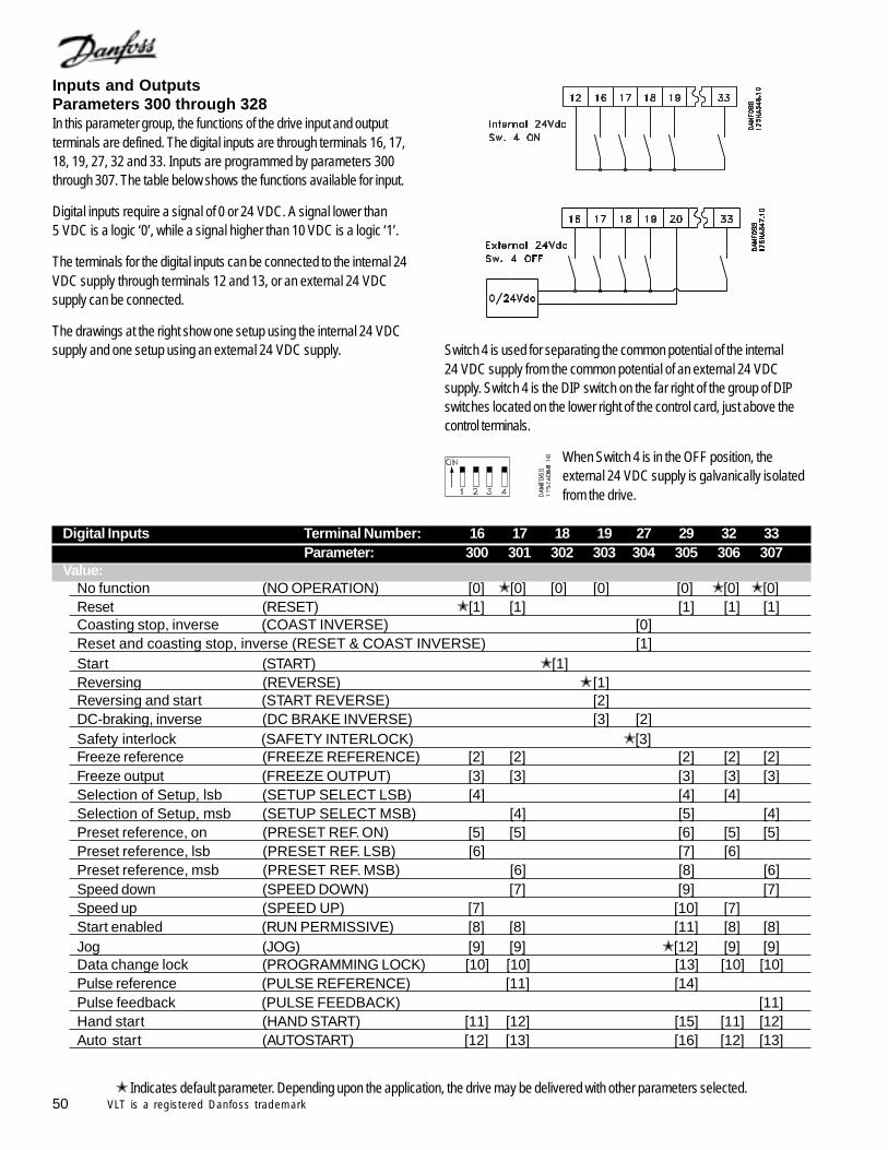
50 VLT is a registered Danfoss trademark
Inputs and OutputsParameters 300 through 328In this parameter group, the functions of the drive input and outputterminals are defined. The digital inputs are through terminals 16, 17,18, 19, 27, 32 and 33. Inputs are programmed by parameters 300through 307. The table below shows the functions available for input.
Digital inputs require a signal of 0 or 24 VDC. A signal lower than5 VDC is a logic ‘0’, while a signal higher than 10 VDC is a logic ‘1’.
The terminals for the digital inputs can be connected to the internal 24VDC supply through terminals 12 and 13, or an external 24 VDCsupply can be connected.
The drawings at the right show one setup using the internal 24 VDCsupply and one setup using an external 24 VDC supply.
Indicates default parameter. Depending upon the application, the drive may be delivered with other parameters selected.
Switch 4 is used for separating the common potential of the internal24 VDC supply from the common potential of an external 24 VDCsupply. Switch 4 is the DIP switch on the far right of the group of DIPswitches located on the lower right of the control card, just above thecontrol terminals.
When Switch 4 is in the OFF position, theexternal 24 VDC supply is galvanically isolatedfrom the drive.
Digital Inputs Terminal Number: 16 17 18 19 27 29 32 33Parameter: 300 301 302 303 304 305 306 307
Value:No function (NO OPERATION) [0] [0] [0] [0] [0] [0] [0]Reset (RESET) [1] [1] [1] [1] [1]Coasting stop, inverse (COAST INVERSE) [0]Reset and coasting stop, inverse (RESET & COAST INVERSE) [1]Start (START) [1]Reversing (REVERSE) [1]Reversing and start (START REVERSE) [2]DC-braking, inverse (DC BRAKE INVERSE) [3] [2]Safety interlock (SAFETY INTERLOCK) [3]Freeze reference (FREEZE REFERENCE) [2] [2] [2] [2] [2]Freeze output (FREEZE OUTPUT) [3] [3] [3] [3] [3]Selection of Setup, lsb (SETUP SELECT LSB) [4] [4] [4]Selection of Setup, msb (SETUP SELECT MSB) [4] [5] [4]Preset reference, on (PRESET REF. ON) [5] [5] [6] [5] [5]Preset reference, lsb (PRESET REF. LSB) [6] [7] [6]Preset reference, msb (PRESET REF. MSB) [6] [8] [6]Speed down (SPEED DOWN) [7] [9] [7]Speed up (SPEED UP) [7] [10] [7]Start enabled (RUN PERMISSIVE) [8] [8] [11] [8] [8]Jog (JOG) [9] [9] [12] [9] [9]Data change lock (PROGRAMMING LOCK) [10] [10] [13] [10] [10]Pulse reference (PULSE REFERENCE) [11] [14]Pulse feedback (PULSE FEEDBACK) [11]Hand start (HAND START) [11] [12] [15] [11] [12]Auto start (AUTOSTART) [12] [13] [16] [12] [13]
51VLT is a registered Danfoss trademark
Function:In parameters 300 through 307, Digital Inputs, the functions ofterminals 16 through 33 are selected.
These options are shown in the table on the previous page.
Description of choice:No Function is selected if the drive is not to react to signals transmittedto the terminal.
Reset allows reset of the drive after a resettable fault. Not all faults canbe reset without removing and reapplying the input power. Faults thatrequire the removal of input power are called trip lock faults. SeeWarnings and Alarms.
Coasting Stop, Inverse is used to release the motor immediately byturning off the output transistors. The motor will coast freely to a stop.Inverse indicates a closed terminal sends the stop signal. Logic ‘0’implements coasting to a stop.
Reset and Coasting Stop, Inverse is used for activating coastingstop at the same time as reset. Inverse indicates a closed terminalsends the stop signal. Logic ‘0’ implements coasting stop and reset.
DC Braking, Inverse is used for stopping the motor by energizing itwith a DC voltage for a given time, as set by parameters 114 and 115.Inverse indicates a closed terminal sends the braking signal. Logic ‘0’implements DC braking. See the DC braking parameters.
Safety Interlock is the same as Coasting Stop, Inverse, except SafetyInterlock generates an alarm message on the display when terminal 27is logic ‘0’. The alarm message will also be active through digital outputs42 and 45 and relay outputs 1 and 2, if programmed for SafetyInterlock.
Do not choose Safety Interlock for drives withsoftware version 1.03. See parameter 624 todetermine software version of drive.
Start is selected for a remote Start/Stop command.Logic ‘1’ = Start. Logic ‘0’ = Stop.
Reversing is used for changing the direction of rotation of the motor.Logic ‘0’ is for forward. Logic ‘1’ is for reverse. The drive can be safelyreversed while it is driving the motor. The reversing signal onlychanges the direction of rotation, it does not activate the start function. Itis not active in Closed Loop mode.
Reversing and Start is used for Start/Stop and reversing using thesame signal. A start signal through terminal 18 starts the drive in theforward direction. If both terminal 18 and a reversing and start terminalare given a logic ‘1’ at the same time, the drive will not start. It is notactive in Closed Loop.
Freeze Reference freezes the present reference. The frozenreference can only be changed by means of Speed Up or SpeedDown. The frozen reference is saved after a stop command and whenpower is removed.
Freeze Output freezes the present output frequency. The frozenoutput frequency can now only be changed by means of Speed Up orSpeed Down.
If Freeze Output is active, the drive cannot bestopped via terminal 18.
To stop the drive when Freeze Output is active, one of the fourmethods listed below must be used.
- Turn off the Freeze Output function and perform a normal stop.- Press the keypad Off/Stop key.- Remove the control voltage to terminal 27.- If terminal 19 is programmed in parameter 303 for DC Brake
Inverse, remove the control voltage to it.
Selection of Setup, Lsb* and Selection of Setup, Msb** enablesdigital selection of the four possible setups. To enable this, parameter002 Active Setup must be set to Multi Setup.
Setup, Msb Setup, Lsb Setup 1 0 0 Setup 2 0 1 Setup 3 1 0 Setup 4 1 1
*Lsb - Least significant bit. **Msb - Most significant bit.
Preset Reference, on is used for switching between remote controlledreference and preset reference. This assumes that Remote/preset hasbeen selected in parameter 210, Reference Type. Logic ‘0’ = remotecontrolled references active; logic ‘1’ = one of the four preset refer-ences is active in accordance with the table below.
Preset Reference, Lsb and Preset reference, Msb enables achoice of one of the four preset references, in accordance with the tablebelow.
Preset ref. msb Preset ref. lsb Preset ref. 1 0 0 Preset ref. 2 0 1 Preset ref. 3 1 0 Preset ref. 4 1 1
Speed Up and Speed Down are selected if digital control of the up/down speed is desired. This function is only active if Freeze Referenceor Freeze Output has been selected.
52 VLT is a registered Danfoss trademark
As long as there is a logic ‘1’ on the terminal selected for Speed Up, thereference or the output frequency will increase by the Ramp-up Timeset in parameter 206.
As long as there is a logic ‘1’ on the terminal selected for Speed Down,the reference or the output frequency will decrease by the Ramp-downTime set in parameter 207.
Pulses (logic ‘1’ minimum high for 3 ms and a minimum pause of 3 ms)will lead to a change of speed of 0.1% (reference) or 0.1 Hz (outputfrequency).
Example:Terminal Terminal Freeze ref./
(16) (17) Freeze output No speed change 0 0 1 Speed down 0 1 1 Speed up 1 0 1 Speed down 1 1 1
The speed reference frozen through the control panel can be changedeven if the drive has stopped. In addition, the frozen reference will beretained in memory after power interruption.
Run Permissive. Run Permissive is used to require a second “runpermission” signal in addition to the normal run command, either inHand or Auto mode. When a run command alone is given, the displaywill show RUN REQ., but the drive will not start. The drive can alsoindicate that a run has been requested through one of the transistorizedor relay outputs. When, in addition to the run command, a logic ‘1’ isapplied to the Run Permissive terminal, the drive will run. If more thanone terminal is programmed for Run Permissive, a logic ‘1’ at any ofthese terminals will allow the drive to run.
Jog is used to start the drive and run it at the frequency set inparameter 209, Jog Frequency. Jog is active in both Hand and Automode.
Jog is not active if a stop command has been given through the keypador terminal 27.
Data change lock is selected if changes to parameters are not to bemade via the control panel. It is be possible to change parametersthrough the serial bus.
Pulse reference is selected if the frequency of a pulse train is to beused as a reference signal. 0 Hz corresponds to parameter 204,Minimum Reference. The frequency set in parameter 327, PulseReference, Maximum Frequency corresponds to parameter 205Maximum Reference.
Pulse feedback is selected if the frequency of a pulse train is to beused as a feedback signal. Parameter 328, Pulse Feedback, MaximumFrequency is the pulse frequency that corresponds to maximumfeedback.
Hand start is selected if an external signal is used to switch the driveto Hand mode. A logic ‘1’ (Hand Start active) will start the motor. A logic‘0’ will stop the motor. The drive will then be in OFF/STOP mode,unless there is an active Auto Start signal from an external source.Programming one of the digital inputs for Hand Start will disable theLCP Hand Start and Auto Start keys.
Active Hand and Auto signals from digital in-puts can cause drive to start unexpectedly.Remove power from drive before servicingdriven equipment.
Auto start is selected if an external signal is sent to switch the drive toAuto mode. When a start signal is active on the control terminals or theserial communication port, the drive will start the motor. If Auto Start andHand Start are active at the same time on the control terminals, AutoStart will have the higher priority. If Auto Start and Hand Start are notactive, the motor will stop and the drive will then be in the OFF/STOPmode. Programming one of the digital inputs for Auto Start will disablethe LCP Hand Start and Auto Start keys.
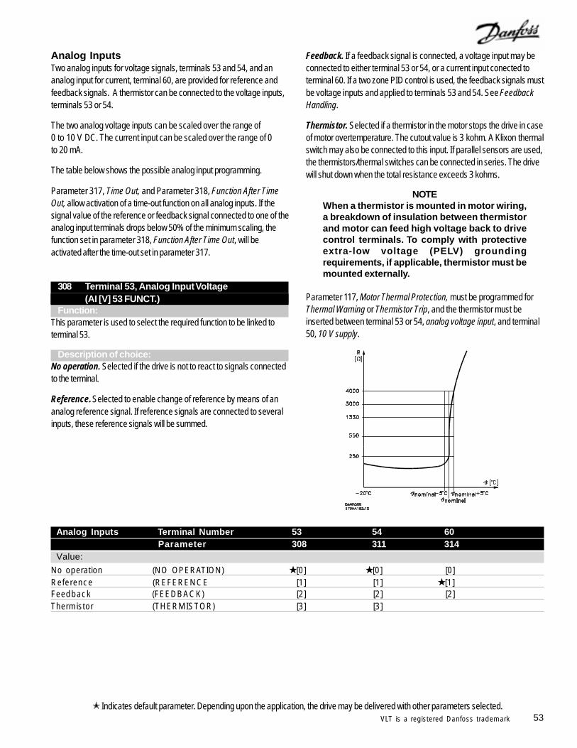
53VLT is a registered Danfoss trademark
Analog InputsTwo analog inputs for voltage signals, terminals 53 and 54, and ananalog input for current, terminal 60, are provided for reference andfeedback signals. A thermistor can be connected to the voltage inputs,terminals 53 or 54.
The two analog voltage inputs can be scaled over the range of0 to 10 V DC. The current input can be scaled over the range of 0to 20 mA.
The table below shows the possible analog input programming.
Parameter 317, Time Out, and Parameter 318, Function After TimeOut, allow activation of a time-out function on all analog inputs. If thesignal value of the reference or feedback signal connected to one of theanalog input terminals drops below 50% of the minimum scaling, thefunction set in parameter 318, Function After Time Out, will beactivated after the time-out set in parameter 317.
Analog Inputs Terminal Number53 (Voltage) 54 (Voltage)60 (Current)
Indicates default parameter. Depending upon the application, the drive may be delivered with other parameters selected.
Analog Inputs Terminal Number 53 54 60Parameter 308 311 314
Value:
No operation (NO OPERATION) [0] [0] [0]Reference (REFERENCE [1] [1] [1]Feedback (FEEDBACK) [2] [2] [2]Thermistor (THERMISTOR) [3] [3]
308 Terminal 53, Analog Input Voltage(AI [V] 53 FUNCT.)
Function:This parameter is used to select the required function to be linked toterminal 53.
Description of choice:No operation. Selected if the drive is not to react to signals connectedto the terminal.
Reference. Selected to enable change of reference by means of ananalog reference signal. If reference signals are connected to severalinputs, these reference signals will be summed.
Feedback. If a feedback signal is connected, a voltage input may beconnected to either terminal 53 or 54, or a current input conected toterminal 60. If a two zone PID control is used, the feedback signals mustbe voltage inputs and applied to terminals 53 and 54. See FeedbackHandling.
Thermistor. Selected if a thermistor in the motor stops the drive in caseof motor overtemperature. The cutout value is 3 kohm. A Klixon thermalswitch may also be connected to this input. If parallel sensors are used,the thermistors/thermal switches can be connected in series. The drivewill shut down when the total resistance exceeds 3 kohms.
NOTEWhen a thermistor is mounted in motor wiring,a breakdown of insulation between thermistorand motor can feed high voltage back to drivecontrol terminals. To comply with protectiveextra-low voltage (PELV) groundingrequirements, if applicable, thermistor must bemounted externally.
Parameter 117, Motor Thermal Protection, must be programmed forThermal Warning or Thermistor Trip, and the thermistor must beinserted between terminal 53 or 54, analog voltage input, and terminal50, 10 V supply.
54 VLT is a registered Danfoss trademark
309 Terminal 53, Minimum Scaling(AI 53 SCALE LOW)
Value:0.0 to 10.0 V 0.0 V
Function:This parameter is used for setting the signal value that corresponds tothe minimum reference or the minimum feedback, parameter 204,Minimum Reference, or parameter 413, Minimum Feedback. SeeReference Handling or Feedback Handling.
Description of choice:Set the required voltage value. For reasons of accuracy, voltagelosses in long signal lines should be compensated for. If the time outfunctions in parameter 317, Time Out, and parameter 318, FunctionAfter Time Out, are to be used, the value must be set to > 1 V.
310 Terminal 53, Maximum Scaling(AI 53 SCALE HIGH)
Value:0.0 to 10.0 V 10.0 V
Function:This parameter is used to set the signal value that corresponds to themaximum reference value or the maximum feedback, parameter 205,Maximum Reference, or parameter 414, Maximum Feedback. SeeReference Handling or Feedback Handling.
Description of choice:Set the required voltage value.
For reasons of accuracy, voltage losses in long signal lines should becompensated for.
311 Terminal 54, Analog Input Voltage(AI [V] 54 FUNCT.)
Value:See the description of parameter 308. No operation
Function:This parameter selects the function of terminal 54.
The input signal is scaled by parameter 312, Terminal 54, MinimumScaling, and by parameter 313, Terminal 54, Maximum Scaling.
Description of choice:See description of parameter 308.
For reasons of accuracy, voltage losses in long signal lines should becompensated for.
312 Terminal 54, Minimum Scaling(AI 54 SCALE LOW)
Value:0.0 to 10.0 V 0.0 V
Function:This parameter is used to set the signal value that corresponds to theminimum reference value or the minimum feedback, parameter 204,Minimum Reference, and parameter 413, Minimum Feedback. SeeReference Handling or Feedback Handling.
Description of choice:Set the required voltage value. For reasons of accuracy, voltagelosses in long signal lines should be compensated for.
If the time out function is to be applied, parameter 317, Time Out, andparameter 318, Function After Time Out, the value must be set to > 1 V.
313 Terminal 54, Maximum Scaling(AI 54 SCALE HIGH)
Value:0.0 to 10.0 V 10.0 V
Function:This parameter is used to set the signal value that corresponds to themaximum reference value or the maximum feedback, parameter 205,Maximum Reference, or parameter 414, Maximum Feedback. SeeReference Handling or Feedback Handling.
Description of choice:Set the required voltage value. For reasons of accuracy, voltagelosses in long signal lines should be compensated for.
314 Terminal 60, Analog Input Current(AI [mA] 60 FUNCT.)
Value:See description of parameter 308. Reference
Function:This parameter selects the function of terminal 60.
Scaling of the input signal is set by parameter 315, Terminal 60,Minimum Scaling, and by parameter 316, Terminal 60, MaximumScaling.
Description of choice:See description of parameter 308, Terminal 53, Analog Input Voltage.
Indicates default parameter. Depending upon the application, the drive may be delivered with other parameters selected.
55VLT is a registered Danfoss trademark
315 Terminal 60, Minimum Scaling(AI 60 SCALE LOW)
Value:0.0 to 20.0 mA 4.0 mA
Function:This parameter determines the signal value that corresponds to theminimum reference or the minimum feedback, parameter 204 MinimumReference, parameter 413, Minimum Feedback. See ReferenceHandling or Feedback Handling.
Description of choice:Set the required current value.
If the time-out function is to be used, parameter 317, Time Out, andparameter 318, Function After Time Out, the value must be set to> 2 mA.
316 Terminal 60, Maximum Scaling(AI 60 SCALE HIGH)
Value:0.0 to 20.0 mA 20.0 mA
Function:This parameter determines the signal value that corresponds to themaximum reference or maximum feedback, parameter 205, MaximumReference Value, or parameter 414, Maximum Feedback. SeeReference Handling or Feedback Handling.
Description of choice:Set the desired current value.
317 Time Out(LIVE ZERO TIME)
Value:1 to 99 sec. 10 sec.
Function:If the signal value of the reference or feedback signal connected to oneof the input terminals 53, 54 or 60 drops to below 50% of the minimumscaling for a longer period than the Live Zero time, the function selectedin parameter 318, Function After Time Out, will be activated.
This function will only be active if, in parameter 309 or 312, a value hasbeen selected for Terminals 53 and 54, Minimum Scaling, that exceeds1 V, or if, in parameter 315, Terminal 60, Minimum Scaling, a valuehas been selected that exceeds 2 mA.
Description of choice:Set the desired time.
318 Function After Time Out(LIVE ZERO FUNCT.)
Value: Off (NO FUNCTION) [0]
Freeze output frequency(FREEZE OUTPUT FREQ.) [1]Stop (STOP) [2]Jog (JOG FREQUENCY) [3]Max. output frequency (MAX FREQUENCY) [4]Stop and trip (STOP AND TRIP) [5]
Function:This is where to select the function to be activated after the end of thetime-out period, parameter 317, Time Out.
If a time-out function occurs at the same time as a bus time-out function,parameter 510, Bus Time Interval Function, the time-out function inparameter 318 will be activated.
Description of choice:The output frequency of the drive can:- go to minimum (NO FUNCTION)- be frozen at the present value (FREEZE OUTPUT
FREQUENCY)- stop (STOP)- run at the jog frequency set in parameter 209
(JOG FREQUENCY)- run at the maximum frequency set in parameter 202
(MAX. FREQUENCY)- stop and send an alarm (STOP AND TRIP)
Indicates default parameter. Depending upon the application, the drive may be delivered with other parameters selected.
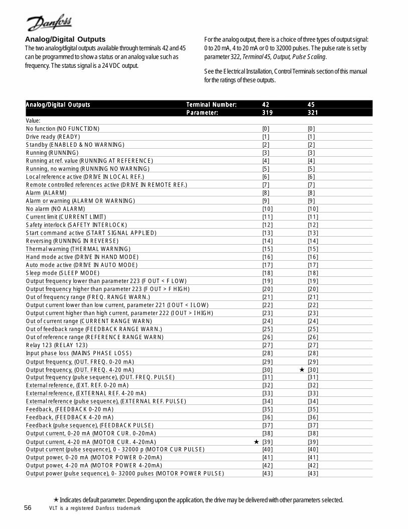
56 VLT is a registered Danfoss trademark
For the analog output, there is a choice of three types of output signal:0 to 20 mA, 4 to 20 mA or 0 to 32000 pulses. The pulse rate is set byparameter 322, Terminal 45, Output, Pulse Scaling.
See the Electrical Installation, Control Terminals section of this manualfor the ratings of these outputs.
Analog/Digital OutputsThe two analog/digital outputs available through terminals 42 and 45can be programmed to show a status or an analog value such asfrequency. The status signal is a 24 VDC output.
Analog/Digital OutputsAnalog/Digital OutputsAnalog/Digital OutputsAnalog/Digital OutputsAnalog/Digital Outputs terminal no.terminal no.terminal no.terminal no.terminal no.Analog/Digital OutputsAnalog/Digital OutputsAnalog/Digital OutputsAnalog/Digital OutputsAnalog/Digital Outputs TTTTTerminal Numbererminal Numbererminal Numbererminal Numbererminal Number::::: 4242424242 4545454545
Parameter:Parameter:Parameter:Parameter:Parameter: 319319319319319 321321321321321Value:No function (NO FUNCTION) [0] [0]Drive ready (READY) [1] [1]Standby (ENABLED & NO WARNING) [2] [2]Running (RUNNING) [3] [3]Running at ref. value (RUNNING AT REFERENCE) [4] [4]Running, no warning (RUNNING NO WARNING) [5] [5]Local reference active (DRIVE IN LOCAL REF.) [6] [6]Remote controlled references active (DRIVE IN REMOTE REF.) [7] [7]Alarm (ALARM) [8] [8]Alarm or warning (ALARM OR WARNING) [9] [9]No alarm (NO ALARM) [10] [10]Current limit (CURRENT LIMIT) [11] [11]Safety interlock (SAFETY INTERLOCK) [12] [12]Start command active (START SIGNAL APPLIED) [13] [13]Reversing (RUNNING IN REVERSE) [14] [14]Thermal warning (THERMAL WARNING) [15] [15]Hand mode active (DRIVE IN HAND MODE) [16] [16]Auto mode active (DRIVE IN AUTO MODE) [17] [17]Sleep mode (SLEEP MODE) [18] [18]Output frequency lower than parameter 223 (F OUT < F LOW) [19] [19]Output frequency higher than parameter 223 (F OUT > F HIGH) [20] [20]Out of frequency range (FREQ. RANGE WARN.) [21] [21]Output current lower than low current, parameter 221 (I OUT < I LOW) [22] [22]Output current higher than high current, parameter 222 (I OUT > I HIGH) [23] [23]Out of current range (CURRENT RANGE WARN) [24] [24]Out of feedback range (FEEDBACK RANGE WARN.) [25] [25]Out of reference range (REFERENCE RANGE WARN) [26] [26]Relay 123 (RELAY 123) [27] [27]Input phase loss (MAINS PHASE LOSS) [28] [28]Output frequency, (OUT. FREQ. 0-20 mA) [29] [29]Output frequency, (OUT. FREQ. 4-20 mA) [30] [30]Output frequency (pulse sequence), (OUT. FREQ. PULSE) [31] [31]External reference, (EXT. REF. 0-20 mA) [32] [32]External reference, (EXTERNAL REF. 4-20 mA) [33] [33]External reference (pulse sequence), (EXTERNAL REF. PULSE) [34] [34]Feedback, (FEEDBACK 0-20 mA) [35] [35]Feedback, (FEEDBACK 4-20 mA) [36] [36]Feedback (pulse sequence), (FEEDBACK PULSE) [37] [37]Output current, 0-20 mA (MOTOR CUR. 0-20mA) [38] [38]Output current, 4-20 mA (MOTOR CUR. 4-20mA) [39] [39]Output current (pulse sequence), 0 - 32000 p (MOTOR CUR PULSE) [40] [40]Output power, 0-20 mA (MOTOR POWER 0-20mA) [41] [41]Output power, 4-20 mA (MOTOR POWER 4-20mA) [42] [42]Output power (pulse sequence), 0- 32000 pulses (MOTOR POWER PULSE) [43] [43]
Indicates default parameter. Depending upon the application, the drive may be delivered with other parameters selected.
57VLT is a registered Danfoss trademark
Function:These outputs can act both as digital and analog outputs. If used as adigital output, a 0 or 24 VDC signal is transmitted. If used as an analogoutput, either a 0 to 20 mA signal, a 4 to 20 mA signal, or a pulsesequence with a frequency of 0 to up to 32,000 Hz is transmitted.
Description of choice:No function. Selected if this output is always to remain off.
Drive ready. The drive’s control card receives a supply voltage andthe drive is ready for operation.
Stand by. The drive is ready for operation, but no start command hasbeen given. No warning.
Running. The drive is running or the drive is in the sleep mode.
Running at ref. value. The drive is at the speed commanded by thereference.
Running, no warning. The drive is running and there are nowarnings.
Local reference active. The motor’s speed is being controlled by thelocal reference through the keypad. This output will also be on if thedrive is set up for local speed control but the jog function has beenactivated.
Remote references active. The motor’s speed is being controlled bya remote reference or a preset speed.
Alarm. The drive has been stopped by an alarm.
Alarm or warning. An alarm or a warning exists in the drive.
No alarm. The drive has no alarm.
Current limit. The output current is greater than or equal to the valueprogrammed in parameter 215, Current Limit. The speed of the driveis being limited to keep the current from increasing.
Safety interlock. Terminal 27 has been programmed for SafetyInterlock in parameter 304, and no control voltage has been applied to it.
Start command active. The drive is either running or it has receiveda run command. This is commonly used in conjunction with the drive’srun permissive control.
Reversing. The drive is running in the reverse direction.
Thermal warning. The temperature limit of either the motor, the drive,or a thermistor connected to an analog input has been exceeded.
Hand mode active. The drive is operating in the Hand run/stop mode.
Auto mode active. The drive is operating in the Auto run/stop mode.
Sleep mode. The drive is stopped because of Sleep Mode.
Output frequency lower than low frequency warning level. Theoutput frequency is lower than the value set in parameter 223,Warning: Low Frequency.
Output frequency higher than high frequency warning level.The output frequency is higher than the value set in parameter 224,Warning: High Frequency.
Out of frequency range. The output frequency is outside thefrequency range programmed in parameter 223, Warning: LowFrequency, and 224, Warning: High Frequency.
Output current lower than low current warning level. The outputcurrent is lower than the value set in parameter 221, Warning: LowCurrent. This can be used to indicate a broken belt.
Output current higher than high current warning level. Theoutput current is higher than the value set in parameter 222, Warning:High Current.
Out of current range. The output current is outside the rangeprogrammed in parameter 221, Warning: Low Current, and parameter222, Warning: High Current.
Out of feedback range. The feedback signal is outside the rangeprogrammed in parameter 227 Warning: Low Feedback, and 228Warning: High feedback.
Out of reference range. The reference is outside the rangeprogrammed in parameter 225, Warning: Low Reference, andparameter 226, Warning: High Reference.
Relay 123. This function is only used when a Profibus option card is installed.
Input phase loss. An incoming power phase is missing.
Output frequency: 0 to 20 mA, 4 to 20 mA, and 0 to 32,000pulses. An output signal proportional to the output frequency in therange from 0 to Output Frequency, High Limit, set by parameter 202.
External reference: 0 to 20 mA, 4 to 20 mA, and 0 to 32,000pulses. An output signal proportional to the resulting reference valuein the range from Minimum Reference to Maximum Reference, set byparameters 204 and 205.
Feedback Minimum to Feedback Maximum: 0 to 20 mA, 4 to 20mA, and 0 to 32,000 pulses. An output signal proportional to thereference value in the range from Minimum Feedback to MaximumFeedback, set by parameters 412 and 413.
Output Current: to 20 mA, 4 to 20 mA, and 0 to 32,000 pulses.An output signal proportional to the output current in the range from 0 tothe maximum drive output current.
Output power: 0 to 20 mA, 4 to 20 mA, and 0 to 32,000 pulses.Generates an output signal proportional to the present output power. 20mA corresponds to the value set by parameter 102, Motor Power.
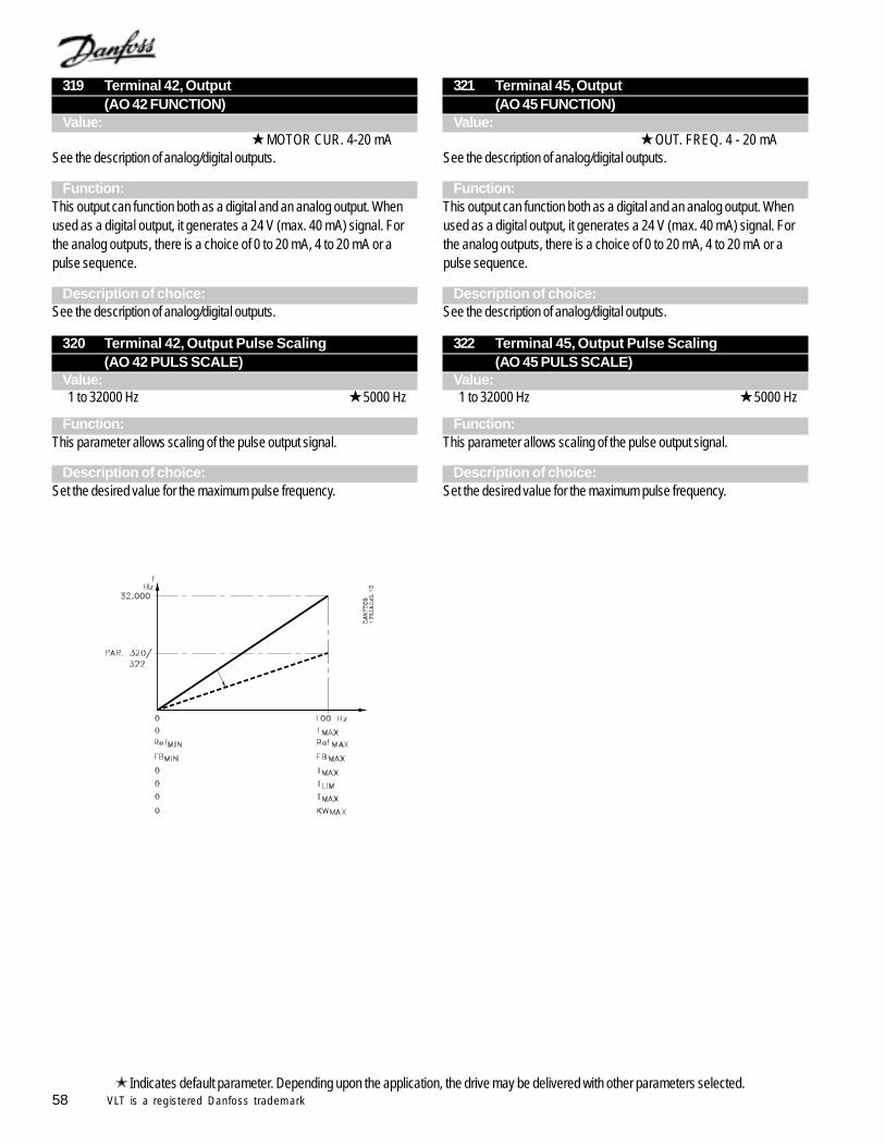
58 VLT is a registered Danfoss trademark
319 Terminal 42, Output(AO 42 FUNCTION)
Value:
MOTOR CUR. 4-20 mA
See the description of analog/digital outputs.
Function:This output can function both as a digital and an analog output. Whenused as a digital output, it generates a 24 V (max. 40 mA) signal. Forthe analog outputs, there is a choice of 0 to 20 mA, 4 to 20 mA or apulse sequence.
Description of choice:See the description of analog/digital outputs.
320 Terminal 42, Output Pulse Scaling(AO 42 PULS SCALE)
Value:1 to 32000 Hz 5000 Hz
Function:This parameter allows scaling of the pulse output signal.
Description of choice:Set the desired value for the maximum pulse frequency.
Indicates default parameter. Depending upon the application, the drive may be delivered with other parameters selected.
321 Terminal 45, Output(AO 45 FUNCTION)
Value: OUT. FREQ. 4 - 20 mA
See the description of analog/digital outputs.
Function:This output can function both as a digital and an analog output. Whenused as a digital output, it generates a 24 V (max. 40 mA) signal. Forthe analog outputs, there is a choice of 0 to 20 mA, 4 to 20 mA or apulse sequence.
Description of choice:See the description of analog/digital outputs.
322 Terminal 45, Output Pulse Scaling(AO 45 PULS SCALE)
Value:1 to 32000 Hz 5000 Hz
Function:This parameter allows scaling of the pulse output signal.
Description of choice:Set the desired value for the maximum pulse frequency.
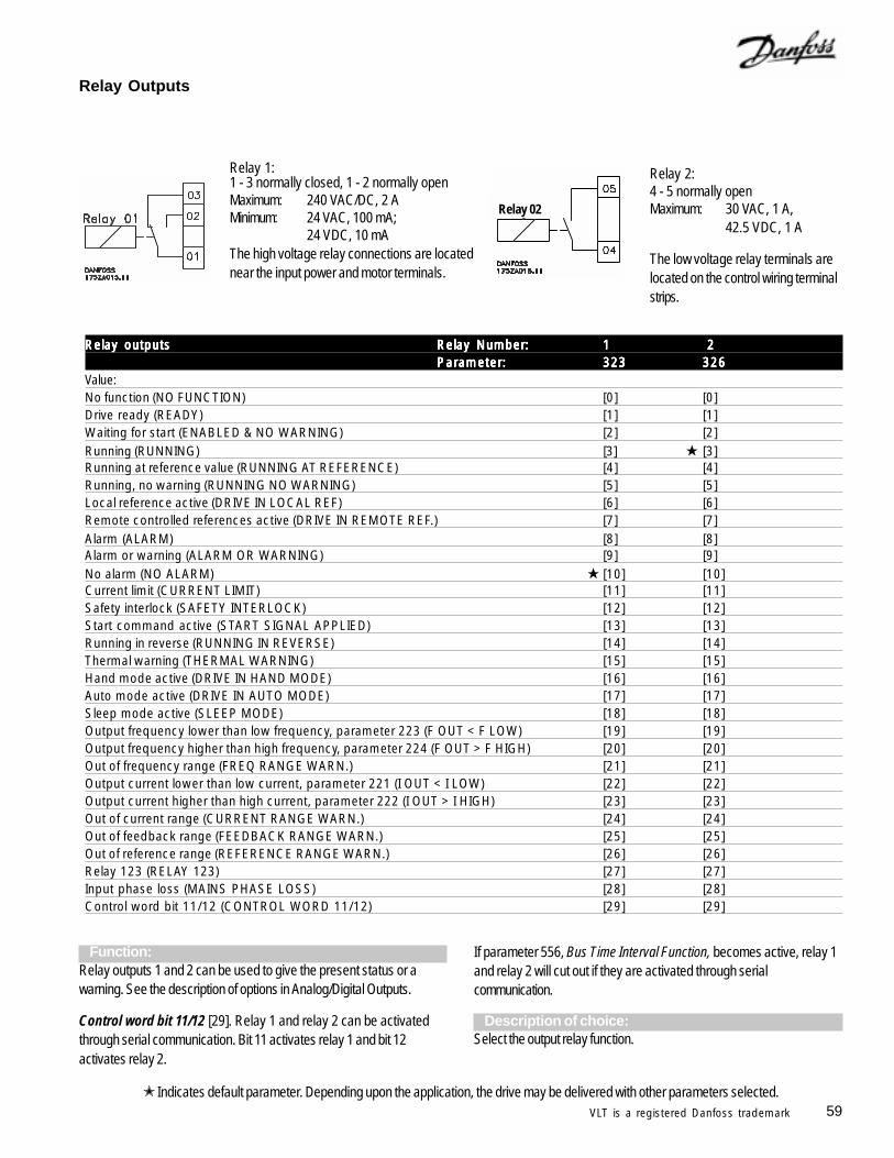
59VLT is a registered Danfoss trademark
Relay outputsRelay outputsRelay outputsRelay outputsRelay outputs Relay Number:Relay Number:Relay Number:Relay Number:Relay Number: 11111 2 2 2 2 2Parameter:Parameter:Parameter:Parameter:Parameter: 323323323323323 326326326326326
Value:No function (NO FUNCTION) [0] [0]Drive ready (READY) [1] [1]Waiting for start (ENABLED & NO WARNING) [2] [2]Running (RUNNING) [3] [3]Running at reference value (RUNNING AT REFERENCE) [4] [4]Running, no warning (RUNNING NO WARNING) [5] [5]Local reference active (DRIVE IN LOCAL REF) [6] [6]Remote controlled references active (DRIVE IN REMOTE REF.) [7] [7]Alarm (ALARM) [8] [8]Alarm or warning (ALARM OR WARNING) [9] [9]No alarm (NO ALARM) [10] [10]Current limit (CURRENT LIMIT) [11] [11]Safety interlock (SAFETY INTERLOCK) [12] [12]Start command active (START SIGNAL APPLIED) [13] [13]Running in reverse (RUNNING IN REVERSE) [14] [14]Thermal warning (THERMAL WARNING) [15] [15]Hand mode active (DRIVE IN HAND MODE) [16] [16]Auto mode active (DRIVE IN AUTO MODE) [17] [17]Sleep mode active (SLEEP MODE) [18] [18]Output frequency lower than low frequency, parameter 223 (F OUT < F LOW) [19] [19]Output frequency higher than high frequency, parameter 224 (F OUT > F HIGH) [20] [20]Out of frequency range (FREQ RANGE WARN.) [21] [21]Output current lower than low current, parameter 221 (I OUT < I LOW) [22] [22]Output current higher than high current, parameter 222 (I OUT > I HIGH) [23] [23]Out of current range (CURRENT RANGE WARN.) [24] [24]Out of feedback range (FEEDBACK RANGE WARN.) [25] [25]Out of reference range (REFERENCE RANGE WARN.) [26] [26]Relay 123 (RELAY 123) [27] [27]Input phase loss (MAINS PHASE LOSS) [28] [28]Control word bit 11/12 (CONTROL WORD 11/12) [29] [29]
Relay Outputs
Relay 1: Relay 2:4 - 5 normally openMaximum: 30 VAC, 1 A,
42.5 VDC, 1 A
The low voltage relay terminals arelocated on the control wiring terminalstrips.
Function:Relay outputs 1 and 2 can be used to give the present status or awarning. See the description of options in Analog/Digital Outputs.
Control word bit 11/12 [29]. Relay 1 and relay 2 can be activatedthrough serial communication. Bit 11 activates relay 1 and bit 12activates relay 2.
Indicates default parameter. Depending upon the application, the drive may be delivered with other parameters selected.
1 - 3 normally closed, 1 - 2 normally openMaximum: 240 VAC/DC, 2 AMinimum: 24 VAC, 100 mA;
24 VDC, 10 mAThe high voltage relay connections are locatednear the input power and motor terminals.
If parameter 556, Bus Time Interval Function, becomes active, relay 1and relay 2 will cut out if they are activated through serialcommunication.
Description of choice:Select the output relay function.
Relay 02
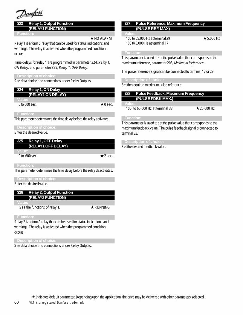
60 VLT is a registered Danfoss trademark
323 Relay 1, Output Function(RELAY1 FUNCTION)
Function: NO ALARM
Relay 1 is a form C relay that can be used for status indications andwarnings. The relay is activated when the programmed conditionoccurs.
Time delays for relay 1 are programmed in parameter 324, Relay 1,ON Delay, and parameter 325, Relay 1, OFF Delay.
Description of choice:See data choice and connections under Relay Outputs.
324 Relay 1, ON Delay(RELAY1 ON DELAY)
Value:0 to 600 sec. 0 sec.
Function:This parameter determines the time delay before the relay activates.
Description of choice:Enter the desired value.
325 Relay 1, OFF Delay(RELAY1 OFF DELAY)
Value:0 to 600 sec. 2 sec.
Function:This parameter determines the time delay before the relay deactivates.
Description of choice:Enter the desired value.
326 Relay 2, Output Function(RELAY2 FUNCTION)
Value: See the functions of relay 1. RUNNING
Function:Relay 2 is a form A relay that can be used for status indications andwarnings. The relay is activated when the programmed conditionoccurs.
Description of choice:See data choice and connections under Relay Outputs.
327 Pulse Reference, Maximum Frequency(PULSE REF. MAX)
Value:100 to 65,000 Hz at terminal 29 5,000 Hz100 to 5,000 Hz at terminal 17
Function:This parameter is used to set the pulse value that corresponds to themaximum reference, parameter 205, Maximum Reference.
The pulse reference signal can be connected to terminal 17 or 29.
Description of choice:Set the required maximum pulse reference.
328 Pulse Feedback, Maximum Frequency(PULSE FDBK MAX.)
Value:100 to 65,000 Hz at terminal 33 25,000 Hz
Function:This parameter is used to set the pulse value that corresponds to themaximum feedback value. The pulse feedback signal is connected toterminal 33.
Description of choice:Set the desired feedback value.
Indicates default parameter. Depending upon the application, the drive may be delivered with other parameters selected.
61VLT is a registered Danfoss trademark
Application FunctionsParameters 400 through 427Special functions of the drive are set up in this parameter group. Thisincludes the proportional, integral, derivative controller (PID) andsetting the sleep mode function.
Additionally, this parameter group includes:- Reset function- Flying start- Interference reduction- Loss of load- Carrier frequency- Selection of process units
400 Reset Function (RESET FUNCTION)Value:
Manual reset (MANUAL RESET) [0]Automatic reset x 1 (AUTOMATIC X 1) [1]Automatic reset x 2 (AUTOMATIC X 2) [2]Automatic reset x 3 (AUTOMATIC X 3) [3]Automatic reset x 4 (AUTOMATIC X 4) [4]Automatic reset x 5 (AUTOMATIC X 5) [5]Automatic reset x 10 (AUTOMATIC X 10) [6]Automatic reset x 15 (AUTOMATIC X 15) [7]Automatic reset x 20 (AUTOMATIC X 20) [8]
Infinite automatic reset (INFINITE AUTOMATIC) [9]
Function:This parameter allows a choice of manual or automatic reset after a faulttrip. There is also a choice of the number of times the unit will attempt torestart. The time between each attempt is set in parameter 401,Automatic Restart Time.
Description of choice:If Manual Reset is selected, the Reset key must be pressed or a digitalinput given to reset the drive.
If auto reset after a fault trip is desired, select one of the Automatic resetchoices.
If any automatic reset choices are selected,motor can start without warning.
401 Automatic Restart Time(AUTORESTART TIME)
Value:0 to 600 seconds 10 sec.
Function:This parameter sets the automatic reset time delay until each reset isattempted. One of the automatic resets must be selected in parameter400, Reset Function.
Description of choice:Set the desired time before each restart attempt.
When parameter 402, Flying Start, is enabled,motor may turn forward and reverse a fewrevolutions even with motor stopped. In highlydynamic pumping processes, it is recommendedto disable Flying Start function.
402 Flying Start (FLYING START)Value: Disable (DISABLE) [0]
Enable (ENABLE) [1]DC brake and start (DC BRAKE AND START) [3]
Function:This function makes it possible for the drive to ‘catch’ a rotating motorwhen the drive is started. The drive will sense the speed of rotation anddirection of rotation of the motor and synchronize with it.
This function is active whenever a start command is present.
For the drive to catch the spinning motor, the motor speed must belower than the maximum frequency set in parameter 202.
Description of choice:Select Disable if this function is not required.
Select Enable if the drive is to ‘catch’ and control a rotating motor.
Select DC brake and start if the drive is to brake the motor by means ofthe DC brake first, and then start. Ensure that parameters 114 through116, DC Braking, are set appropriately. Select DC brake and start if themotor may be externally driven at a significant speed in the reversedirection.
NOTEFor fan applications, factory setting for FlyingStart is Enable. For pump applications, factorysetting for Flying Start is Disable.
Sleep ModeSleep mode makes it possible to stop the drive when the systemdemand drops below a preset level. When the demand increases to ahigher preset level, the drive will restart. A significant amount of energycan be saved using sleep mode. Unlike a set-back time clock, the driveis always available to run when the demand reaches the preset “wakeup” level. Sleep mode is not active if Local Reference is selected inparameter 203, Reference Handling, or if the Jog function activates viadigital inputs. Sleep mode operates in both Open Loop and ClosedLoop.
Activate sleep mode in parameter 403, Sleep Mode Timer. In thisparameter, set how long the output frequency must be lower than thesleep frequency set in parameter 404, Sleep Frequency, before sleepmode activates. After the set time, the drive will ramp down the motor toa stop, as controlled by parameter 207, Ramp Down Time. If the output
Indicates default parameter. Depending upon the application, the drive may be delivered with other parameters selected.
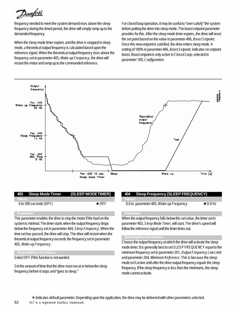
62 VLT is a registered Danfoss trademark
frequency needed to meet the system demand rises above the sleepfrequency during the timed period, the drive will simply ramp up to thedemanded frequency.
When the sleep mode timer expires and the drive is stopped in sleepmode, a theoretical output frequency is calculated based upon thereference signal. When the theoretical output frequency rises above thefrequency set in parameter 405, Wake-up Frequency, the drive willrestart the motor and ramp up to the commanded reference.
For closed loop operation, it may be useful to “over satisfy” the systembefore putting the drive into sleep mode. The boost setpoint parameterprovides for this. After the sleep mode timer expires, the drive will resetthe set point based on the value in parameter 406, Boost Setpoint.Once this new setpoint is satisfied, the drive enters sleep mode. Asetting of 100% in parameter 406, Boost Setpoint, indicates no setpointboost. Boost setpoint is only active in Closed Loop, selected inparameter 100, Configuration.
403 Sleep Mode Timer (SLEEP MODE TIMER)Value:0 to 300 seconds (OFF) OFF
Function:This parameter enables the drive to stop the motor if the load on thesystem is minimal. The timer starts when the output frequency dropsbelow the frequency set in parameter 404, Sleep Frequency. When thetime set has passed, the drive will stop. The drive will restart when thetheoretical output frequency exceeds the frequency set in parameter405, Wake-up Frequency.
Description of choice:Select OFF if this function is not wanted.
Set the amount of time that the drive must run at or below the sleepfrequency before it stops and “goes to sleep.”
404 Sleep Frequency (SLEEP FREQUENCY)Value:0.0 to parameter 405, Wake-up Frequency 0.0 Hz
Function:When the output frequency falls below this set value, the timer set inparameter 403, Sleep Mode Timer, will start. The drive’s speed willfollow the reference signal until the timer times out.
Description of choice:Choose the output frequency at which the drive will activate the sleepmode timer. It is generally best to set SLEEP FREQUENCY equal to theminimum frequency set in parameter 201, Output Frequency Low Limitand parameter 204, Minimum Reference. This is because the sleepmode isn’t active until after the drive output frequency equals the sleepfrequency. If the sleep frequency is less than the minimums, the sleepmode cannot activate.
Indicates default parameter. Depending upon the application, the drive may be delivered with other parameters selected.
63VLT is a registered Danfoss trademark
405 Wake-up Frequency (WAKEUP FREQUENCY)Value:Parameter 404 to parameter 202, Maximum Frequency
60 Hz
Function:When the theoretical output frequency exceeds the preset value, thedrive restarts the motor.
Description of choice:Set the required frequency.
406 Boost Setpoint (BOOST SETPOINT)Value:0 to 200 % 100 % of setpoint
Function:This function can only be used if Closed Loop has been selected inparameter 100, Configuration.
In some systems, it may advantageous to increase the set point of thesystem before the drive stops the motor. This extends the time that thedrive will be stopped and reduces cycling of the motor.
Description of choice:Set the required Boost Setpoint as a percentage of the resultingreference under normal operation. 100% corresponds to the boost.
407 Switching Frequency (SWITCHING FREQ.)Value:Depends on the current rating of the unit.
Function:The value of this parameter determines the maximum switchingfrequency of the inverter. If Fixed Switching Frequency has beenselected in parameter 408, Interference Reduction Method, this will bethe fixed inverter switching frequency. Changing the switchingfrequency may reduce audible noise from the motor. The outputfrequency of the drive can never be a greater than 1/10 of theswitching frequency.
Description of choice:When the motor is running, the switching frequency may be adjustedby parameter 407, Switching Frequency, until the sound level is as lowas possible.
Switching frequencies higher than 4.5 kHz will result in automaticderating of the maximum continuous output current of the drive. Thederate is linear from 4.5 kHz to the maximum switching frequency of thedrive. At maximum switching frequency, the continuous output currentfrom the drive will be limited to 60% of the rated current. To avoidpossible problems at high load when using a high switching frequency,it may be desirable to select Automatic Switching Frequency Modulationin parameter 408, below.
Switching frequencies higher than 4.5 kHzautomatically derate maximum continuousoutput of drive.
408 Interference Reduction Method(NOISE REDUCTION)
Value: ASFM (ASFM) [0]
Fixed switching freq. (FIXED SWITCHING FREQ.) [1]LC filter fitted (LC-FILTER CONNECTED) [2]
Function:Used to select different methods for reducing the amount of audiblenoise from the motor.
Description of choice:ASFM (Automatic Switching Frequency Modulation) uses themaximum switching frequency possible while providing the outputrequired by the load. The load is automatically monitored and theswitching frequency set accordingly. The maximum switching frequencyis set in parameter 407, Switching Frequency.
Fixed Switching Frequency makes it possible to set a fixed switchingfrequency. The switching frequency is set in parameter 407, SwitchingFrequency.
LC-filter fitted is to be used if an LC filter is installed between the driveand the motor. This prevents excessive heating of the LC filter.
409 Function in Case of No Load(FUNCT. LOW CURR.)
Value:Trip (TRIP) [0]
Warning (WARNING) [1]
Function:This parameter can be used for monitoring the V-belt of a fan or otherpower transmission component to make sure it has not broken. Thisfunction is activated when the output current goes below the current levelset in parameter 221, Warning: Low Current. This function is not activeduring a start until the drive has reached the speed reference. It is alsonot active while the drive is stopped or while it is decelerating to a stop.
Description of choice:In the case of a Trip, the drive will stop the motor if the output currentdrops below the value set in parameter 221.
If Warning is selected, the drive will give a warning if the output currentdrops below the value set in parameter 221.
Indicates default parameter. Depending upon the application, the drive may be delivered with other parameters selected.
64 VLT is a registered Danfoss trademark
410 Function at Input Phase Loss(MAINS FAILURE)
Value:Trip (TRIP) [0]Autoderate & Warning (AUTODERATE & WARNING) [1]Warning (WARNING) [2]
Function:This determines the action of the drive when one of the incoming powerphases is lost. Some action is required to control the level of ripplevoltage on the DC bus to avoid damage to the DC bus capacitors.
Description of choice:At Trip, the drive stops the motor within a few seconds (depending ondrive size).
If Autoderate & Warning is selected, the drive will export a warningand reduce the output current to 30% of maximum current
to maintain
operation.
If Warning is selected, life expectancy of drivewill be reduced when input phase loss persists.
At Warning, only a warning will be exported when an input phase lossoccurs, but in severe cases, other extreme conditions might result in atrip.
Drive display will show MAINS PHASE LOSS.
For drives with software version 2.0 or later, select Autoderate &Warning. Set parameter 412, Trip Delay Overcurrent, to OFF.
At phase loss, the cooling fan of NEMA 12 drivescannot be powered. To avoid overheating, ex-ternal power supply can be connected. ContactDanfoss Graham for further information.
411 Function at Drive Overtemperature(FUNCT. OVERTEMP)
Value:Trip (TRIP) [0]Autoderate & Warning (AUTODERATE & WARNING) [1]
Function:Select the function to be activated when the drive is exposed to anovertemperature condition.
Description of choice:At Trip, the drive stops the motor and exports an alarm.
At Autoderate & Warning, the drive first reduces the switchingfrequency to minimize internal loss. If the overtemperature conditionpersists, the drive reduces the output current until the heat sinktemperature stabilizes. A warning is issued when the function is active.
For drives with software version 2.0 or later, select Autoderate &Warning. Set parameter 412, Trip Delay Overcurrent, to OFF.
412 Trip Delay Overcurrent(OVERLOAD DELAY)
Value:OFF or 0 to 60 sec. 60 sec.
Function:When the output current has reached the current limit set in parameter215, Current Limit, and remains there for the time selected in thisparameter, the drive will trip.
Description of choice:Select how long the drive will run in current limit before it trips.
Indicates default parameter. Depending upon the application, the drive may be delivered with other parameters selected.
65VLT is a registered Danfoss trademark
Feedback Signals in Open LoopIn some drives, feedback signals and feedback parameters are onlyused in closed loop operation. In the VLT 6000, the feedback signalsare also active in open loop operation. Although they don’t effect thespeed of the drive, they can be displayed on the drive’s meters.Parameters 227 and 228 can set high and low limits for the feedbacksignals, which can activate warnings.
For open or closed loop operation, the feedback signal is scaled inparameters 413 and 414 Minimum and Maximum Feedback, and theunit displayed is chosen in parameter 415, Process Units.
413 Minimum Feedback(MIN. FEEDBACK)
Value:-999,999.999 to Maximum Feedback, Parameter 414 0.000
Function:Parameters 413 Minimum Feedback and 414 Maximum Feedback,are used to scale the feedback signal.
Description of choice:Set the value to be shown on the display when the feedback signal is atits minimum value.
414 Maximum Feedback(MAX. FEEDBACK)
Value:Minimum Feedback to 999,999.999 100.000
Function:See the description of parameter 413, Minimum Feedback.
Description of choice:Set the value to be shown on the display when the feedback signal is atits maximum value.
415 Units Relating to Closed Loop(REF. / FDBK. UNIT)
Value:No unit [0] °C [21]
% [1] GPM [22]rpm [2] gal/s [23]ppm [3] gal/min [24]pulse/s [4] gal/h [25]l/s [5] lb/s [26]l/min [6] lb/min [27]l/h [7] lb/h [28]kg/s [8] CFM [29]kg/min [9] ft3/s [30]kg/h [10] ft3/min [31]m3/s [11] ft3/h [32]m3/min [12] ft/s [33]m3/h [13] in wg [34]m/s [14] ft wg [35]mbar [15] PSI [36]bar [16] lb/in2 [37]Pa [17] HP [38]kPa [18] °F [39]m wg [19]kW [20]
Function:Selects the unit shown on the feedback display.
The selected unit is used if Reference [unit] or Feedback [unit] hasbeen selected in one of the parameters 007 through 010, as well as inthe Display Mode. It will be the unit for Minimum/Maximum Feedback.In Closed Loop, the unit is also used as the unit for Minimum/MaximumReference and Minimum/Maximum Feedback, as well as Setpoint 1and Setpoint 2.
Description of choice:Select the unit for the reference/feedback signal.
Indicates default parameter. Depending upon the application, the drive may be delivered with other parameters selected.
66 VLT is a registered Danfoss trademark
PID for Process RegulationThe built-in proportional, integral, derivative (PID) controller in thedrive maintains a constant condition (pressure, temperature, flow, etc.)in the system. It adjusts motor speed based upon a reference and/orsetpoint and the feedback signal. The PID controller is activated bysetting parameter 100, Configuration, to Closed loop.
A transmitter supplies the PID controller with a feedback signal from theprocess to indicate its current state. The type of feedback signal in usedepends upon the type of process.
This means that deviations that occur between the reference/setpointand the actual process state are sensed. Such deviations arecompensated for by the PID regulator by adjusting the output frequencyas required by the difference (or error) between the reference/setpointand the feedback signal.
The PID controller in the drive has been designed for use in HVACapplications and to perform a number of specialized functions.Previously, it was necessary for a building management system tohandle these special functions by installing extra modules to programthe system.
With the VLT 6000, there is no need for extra modules to be installed.Only the reference and/or setpoint and a selected feedback signal needto be programmed. An advanced feature of the VLT 6000 is the drive’sability to accept two feedback signals, making two-zone regulationpossible.
Voltage drop in long control cables can be compensated for by usingthe scaling parameters for the analog inputs.
FeedbackThe feedback signal must be connected to the drive according to thetable below, depending on the type of feedback signal and the settingsof the associated parameters listed.
Feedback type Terminal Parameters Pulse 33 307 Voltage 53 or 54 308, 309, 310 or
311, 312, 313 Current 60 314, 315, 316 Bus feedback 1* 68 and 69 537 Bus feedback 2* 68 and 69 538* The bus feedbacks can only be set by serial communication.
If two analog feedback signals are to be used, they both must bevoltage signals.
The Minimum Feedback and Maximum Feedback, parameters 413and 414, must be set for the feedback signals. The type of process unitfor the signals is selected in parameter 415, Process Units.
Reference (Setpoint)In parameter 205, Maximum Reference, the maximum value of the sumof all reference signals is set.
The Minimum Reference, set in parameter 204, indicates the smallestvalue that the resulting reference can assume.
The reference range cannot exceed the feedback range.
If multiple Preset References are required, use multiple setups or setthem in parameters 211 to 214 Preset Reference. See ReferenceHandling.
If a current signal is used as a feedback signal, voltage can be used asan analog reference. Use the table below to decide which terminal touse and which parameters to program.
Reference type Terminal Parameters Pulse 17 or 29 301 or 305 Voltage 53 or 54 308, 309, 310 or
311, 312, 313 Current 60 314, 315, 316 Preset reference 211, 212, 213, 214 Setpoints 418, 419 Bus reference * 68 and 69* The bus reference can only be set by serial communication.
Terminals that are not used should be set to No function.
Inverse RegulationNormal regulation means that the motor speed increases when thereference/setpoint is higher than the feedback signal. Inverse regula-tion means that the motor speed decreases when the reference/setpointis higher than the feedback signal. If there is a need for inverseregulation, inverse must be programmed in parameter 420, PIDNormal/Inverse Control.
Anti-windupThe process controller is factory set with an active anti-windup function.This function ensures that when either a frequency limit or a current limitis reached, the integrator will be reset to zero. If the frequency limit orcurrent limit is cleared, the integrator will turn on again. This functioncan be disabled in parameter 421, PID Anti-windup.
Start-up ConditionsIn some applications, the optimum setting of the process regulator takesa long time to reach. In such cases, a start-up frequency can beentered in parameter 422, PID Start-up Frequency. The drive willramp directly to this frequency before PID control begins. This avoidscontrol by deviation between the reference/setpoint and the actual stateof the process during acceleration. It also avoids overshoot of theprocess requirement during acceleration due to lag in the feedbacksignal.
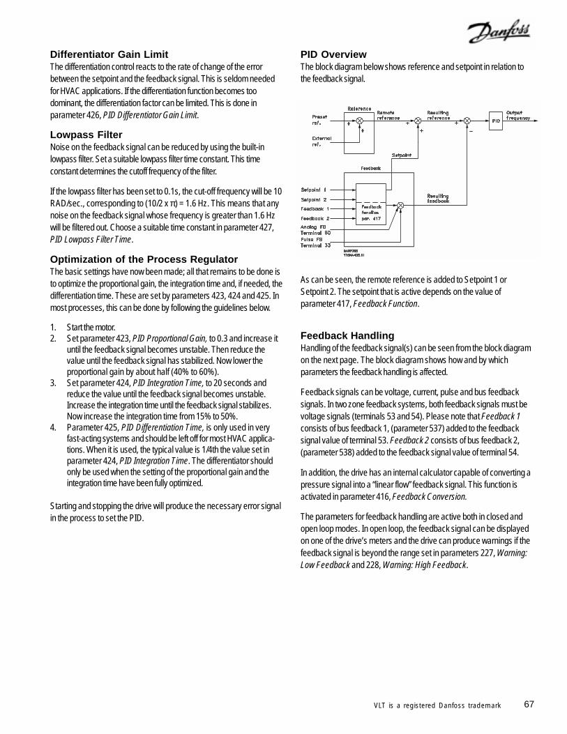
67VLT is a registered Danfoss trademark
Differentiator Gain LimitThe differentiation control reacts to the rate of change of the errorbetween the setpoint and the feedback signal. This is seldom neededfor HVAC applications. If the differentiation function becomes toodominant, the differentiation factor can be limited. This is done inparameter 426, PID Differentiator Gain Limit.
Lowpass FilterNoise on the feedback signal can be reduced by using the built-inlowpass filter. Set a suitable lowpass filter time constant. This timeconstant determines the cutoff frequency of the filter.
If the lowpass filter has been set to 0.1s, the cut-off frequency will be 10RAD/sec., corresponding to (10/2 x π) = 1.6 Hz. This means that anynoise on the feedback signal whose frequency is greater than 1.6 Hzwill be filtered out. Choose a suitable time constant in parameter 427,PID Lowpass Filter Time.
Optimization of the Process RegulatorThe basic settings have now been made; all that remains to be done isto optimize the proportional gain, the integration time and, if needed, thedifferentiation time. These are set by parameters 423, 424 and 425. Inmost processes, this can be done by following the guidelines below.
1. Start the motor.2. Set parameter 423, PID Proportional Gain, to 0.3 and increase it
until the feedback signal becomes unstable. Then reduce thevalue until the feedback signal has stabilized. Now lower theproportional gain by about half (40% to 60%).
3. Set parameter 424, PID Integration Time, to 20 seconds andreduce the value until the feedback signal becomes unstable.Increase the integration time until the feedback signal stabilizes.Now increase the integration time from 15% to 50%.
4. Parameter 425, PID Differentiation Time, is only used in veryfast-acting systems and should be left off for most HVAC applica-tions. When it is used, the typical value is 1/4th the value set inparameter 424, PID Integration Time. The differentiator shouldonly be used when the setting of the proportional gain and theintegration time have been fully optimized.
Starting and stopping the drive will produce the necessary error signalin the process to set the PID.
PID OverviewThe block diagram below shows reference and setpoint in relation tothe feedback signal.
As can be seen, the remote reference is added to Setpoint 1 orSetpoint 2. The setpoint that is active depends on the value ofparameter 417, Feedback Function.
Feedback HandlingHandling of the feedback signal(s) can be seen from the block diagramon the next page. The block diagram shows how and by whichparameters the feedback handling is affected.
Feedback signals can be voltage, current, pulse and bus feedbacksignals. In two zone feedback systems, both feedback signals must bevoltage signals (terminals 53 and 54). Please note that Feedback 1consists of bus feedback 1, (parameter 537) added to the feedbacksignal value of terminal 53. Feedback 2 consists of bus feedback 2,(parameter 538) added to the feedback signal value of terminal 54.
In addition, the drive has an internal calculator capable of converting apressure signal into a “linear flow” feedback signal. This function isactivated in parameter 416, Feedback Conversion.
The parameters for feedback handling are active both in closed andopen loop modes. In open loop, the feedback signal can be displayedon one of the drive’s meters and the drive can produce warnings if thefeedback signal is beyond the range set in parameters 227, Warning:Low Feedback and 228, Warning: High Feedback.
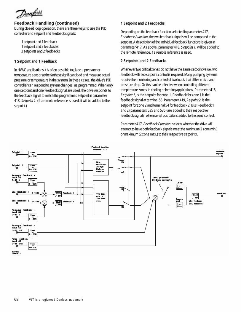
68 VLT is a registered Danfoss trademark
Feedback Handling (continued)During closed loop operation, there are three ways to use the PIDcontroller and setpoint and feedback signals:
1 setpoint and 1 feedback1 setpoint and 2 feedbacks2 setpoints and 2 feedbacks
1 Setpoint and 1 Feedback
In HVAC applications it is often possible to place a pressure ortemperature sensor at the farthest significant load and measure actualpressure or temperature in the system. In these cases, the drive's PIDcontroller can respond to system changes, as programmed. When onlyone setpoint and one feedback signal are used, the drive responds tothe feedback signal to match the programmed setpoint in parameter418, Setpoint 1. (If a remote reference is used, it will be added to thesetpoint.)
1 Setpoint and 2 Feedbacks
Depending on the feedback function selected in parameter 417,Feedback Function, the two feedback signals will be compared to thesetpoint. A description of the individual feedback functions is given inparameter 417. As above, parameter 418, Setpoint 1, will be added tothe remote reference, if a remote reference is used.
2 Setpoints and 2 Feedbacks
Whenever two critical zones do not have the same setpoint value, twofeedback with two setpoint control is required. Many pumping systemsrequire the monitoring and control of two loads that differ in size andpressure drop. Or this can be effective when controlling differenttemperature zones in cooling or heating applications. Parameter 418,Setpoint 1, is the setpoint for zone 1. Feedback for zone 1 is thefeedback signal at terminal 53. Parameter 419, Setpoint 2, is thesetpoint for zone 2 and terminal 54 for feedback 2. Bus Feedback 1and 2 (parameters 535 and 536) are added to their respectivefeedback signals, when serial bus data is added to the zone control.
Parameter 417, Feedback Function, selects whether the drive willattempt to have both feedback signals meet the minimum (2 zone min.)or maximum (2 zone max.) to their respective setpoints.
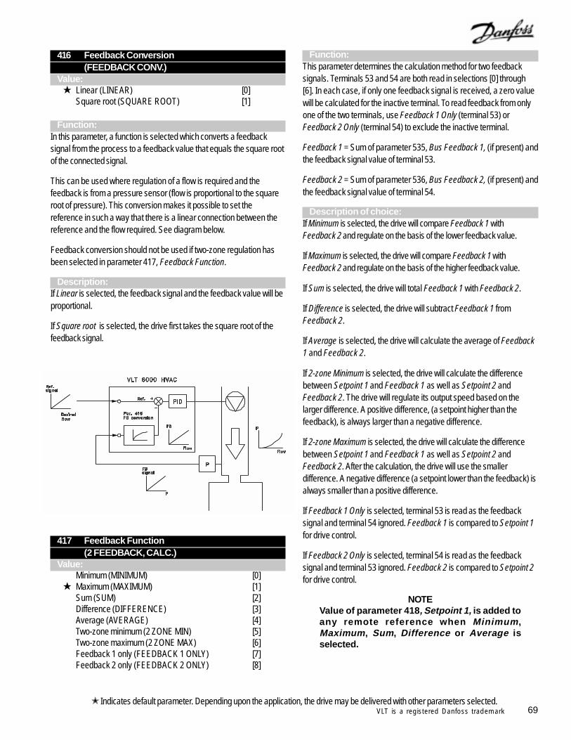
69VLT is a registered Danfoss trademark
416 Feedback Conversion(FEEDBACK CONV.)
Value: Linear (LINEAR) [0]
Square root (SQUARE ROOT) [1]
Function:In this parameter, a function is selected which converts a feedbacksignal from the process to a feedback value that equals the square rootof the connected signal.
This can be used where regulation of a flow is required and thefeedback is from a pressure sensor (flow is proportional to the squareroot of pressure). This conversion makes it possible to set thereference in such a way that there is a linear connection between thereference and the flow required. See diagram below.
Feedback conversion should not be used if two-zone regulation hasbeen selected in parameter 417, Feedback Function.
Description:If Linear is selected, the feedback signal and the feedback value will beproportional.
If Square root is selected, the drive first takes the square root of thefeedback signal.
417 Feedback Function(2 FEEDBACK, CALC.)
Value:Minimum (MINIMUM) [0]
Maximum (MAXIMUM) [1]Sum (SUM) [2]Difference (DIFFERENCE) [3]Average (AVERAGE) [4]Two-zone minimum (2 ZONE MIN) [5]Two-zone maximum (2 ZONE MAX) [6]Feedback 1 only (FEEDBACK 1 ONLY) [7]Feedback 2 only (FEEDBACK 2 ONLY) [8]
Function:This parameter determines the calculation method for two feedbacksignals. Terminals 53 and 54 are both read in selections [0] through[6]. In each case, if only one feedback signal is received, a zero valuewill be calculated for the inactive terminal. To read feedback from onlyone of the two terminals, use Feedback 1 Only (terminal 53) orFeedback 2 Only (terminal 54) to exclude the inactive terminal.
Feedback 1 = Sum of parameter 535, Bus Feedback 1, (if present) andthe feedback signal value of terminal 53.
Feedback 2 = Sum of parameter 536, Bus Feedback 2, (if present) andthe feedback signal value of terminal 54.
Description of choice:If Minimum is selected, the drive will compare Feedback 1 withFeedback 2 and regulate on the basis of the lower feedback value.
If Maximum is selected, the drive will compare Feedback 1 withFeedback 2 and regulate on the basis of the higher feedback value.
If Sum is selected, the drive will total Feedback 1 with Feedback 2.
If Difference is selected, the drive will subtract Feedback 1 fromFeedback 2.
If Average is selected, the drive will calculate the average of Feedback1 and Feedback 2.
If 2-zone Minimum is selected, the drive will calculate the differencebetween Setpoint 1 and Feedback 1 as well as Setpoint 2 andFeedback 2. The drive will regulate its output speed based on thelarger difference. A positive difference, (a setpoint higher than thefeedback), is always larger than a negative difference.
If 2-zone Maximum is selected, the drive will calculate the differencebetween Setpoint 1 and Feedback 1 as well as Setpoint 2 andFeedback 2. After the calculation, the drive will use the smallerdifference. A negative difference (a setpoint lower than the feedback) isalways smaller than a positive difference.
If Feedback 1 Only is selected, terminal 53 is read as the feedbacksignal and terminal 54 ignored. Feedback 1 is compared to Setpoint 1for drive control.
If Feedback 2 Only is selected, terminal 54 is read as the feedbacksignal and terminal 53 ignored. Feedback 2 is compared to Setpoint 2for drive control.
NOTEValue of parameter 418, Setpoint 1, is added toany remote reference when Minimum,Maximum, Sum, Difference or Average isselected.
Indicates default parameter. Depending upon the application, the drive may be delivered with other parameters selected.
70 VLT is a registered Danfoss trademark
418 Setpoint 1(SETPOINT 1)
Value:Feedback Minimum to Feedback Maximum 0.000
Function:Setpoint 1 is used to provide the setpoint reference for PID control withone feedback signal. It is also used for the setpoint for zone one intwo-setpoint PID control. External and preset references may be addedto its value.
In open loop, Setpoint 1 should be set to 0 to prevent parameter 417,Feedback Function, from affecting the reference.
See description of parameter 417, Feedback Function.
Description of choice:Set the desired value within the programmed minimum and maximum.The process unit is selected in parameter 415, Process Units.
419 Setpoint 2(SETPOINT 2)
Value: Feedback minimum to Feedback maximum 0.000
Function:Setpoint 2 is used to provide the setpoint reference for zone two intwo-zone PID. In open loop, Setpoint 2 should be set to 0, to preventparameter 417, Feedback Function, from affecting the reference.
See description of parameter 417.
Description of choice:Set the required value. The process unit is selected in parameter 415,Process Units.
420 PID Normal/Inverse Control(PID NOR/INV. CTRL)
Value: Normal (NORMAL) [0]
Inverse (INVERSE) [1]Function:
This determines how the drive’s PID controller responds to an errorbetween the setpoint and feedback.
Used in Closed Loop, (parameter 100).
Description of choice:Select normal when the drive is to reduce the output frequency as thefeedback signal increases.
Select inverse when the drive is to increase the output frequency as thefeedback signal increases.
421 PID Anti-windup(PID ANTI WINDUP)
Value:Off (DISABLE) [0]
On (ENABLE) [1]Function:
It is possible to choose whether the PID controller integrator is tocontinue to sum the error signal when it is not possible to increase ordecrease the output frequency to correct the error.
Used in Closed Loop, parameter 100.
Description of choice:The factory setting is On, which means that the error integrator iscleared if either the current limit, the voltage limit or the maximum orminimum frequency has been reached. The integrator will not functionagain until regulation is possible. Select Off if the integrator is tocontinue integrating even if it is not possible to correct the error.
422 PID Start-up Frequency(PID START VALUE)
Value:Minimum frequency to maximum frequency
(set by parameters 201 and 202) 0 Hz
Function:Each time the drive is given a start command, the start-up frequency isthe speed the drive accelerates to before PID control is activated. Thedrive will follow the acceleration ramp when a start signal is received asif in open loop. When the programmed start-up frequency is reached, itwill change to closed loop operation.
Used in Closed Loop, parameter 100.
Description of choice:Set the required start frequency. For software versions prior to 2.0, donot set this frequency between 0.1 and 7.7 Hz.
If drive is running in current limit before desiredstart frequency is obtained, PID control will notbe activated. To avoid this, start frequency mustbe low enough to ensure drive does not go intocurrent limit. This can be done during operation.
Indicates default parameter. Depending upon the application, the drive may be delivered with other parameters selected.
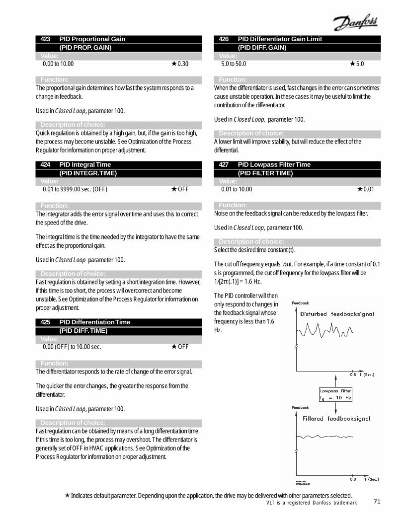
71VLT is a registered Danfoss trademark
423 PID Proportional Gain(PID PROP. GAIN)
Value:0.00 to 10.00 0.30
Function:The proportional gain determines how fast the system responds to achange in feedback.
Used in Closed Loop, parameter 100.
Description of choice:Quick regulation is obtained by a high gain, but, if the gain is too high,the process may become unstable. See Optimization of the ProcessRegulator for information on proper adjustment.
424 PID Integral Time(PID INTEGR.TIME)
Value:0.01 to 9999.00 sec. (OFF) OFF
Function:The integrator adds the error signal over time and uses this to correctthe speed of the drive.
The integral time is the time needed by the integrator to have the sameeffect as the proportional gain.
Used in Closed Loop parameter 100.
Description of choice:Fast regulation is obtained by setting a short integration time. However,if this time is too short, the process will overcorrect and becomeunstable. See Optimization of the Process Regulator for information onproper adjustment.
425 PID Differentiation Time(PID DIFF. TIME)
Value:0.00 (OFF) to 10.00 sec. OFF
Function:The differentiator responds to the rate of change of the error signal.
The quicker the error changes, the greater the response from thedifferentiator.
Used in Closed Loop, parameter 100.
Description of choice:Fast regulation can be obtained by means of a long differentiation time.If this time is too long, the process may overshoot. The differentiator isgenerally set of OFF in HVAC applications. See Optimization of theProcess Regulator for information on proper adjustment.
426 PID Differentiator Gain Limit(PID DIFF. GAIN)
Value:5.0 to 50.0 5.0
Function:When the differentiator is used, fast changes in the error can sometimescause unstable operation. In these cases it may be useful to limit thecontribution of the differentiator.
Used in Closed Loop, parameter 100.
Description of choice:A lower limit will improve stability, but will reduce the effect of thedifferential.
427 PID Lowpass Filter Time(PID FILTER TIME)
Value:0.01 to 10.00 0.01
Function:Noise on the feedback signal can be reduced by the lowpass filter.
Used in Closed Loop, parameter 100.
Description of choice:Select the desired time constant (t).
The cut off frequency equals ½πt. For example, if a time constant of 0.1s is programmed, the cut off frequency for the lowpass filter will be1/[2π (.1)] = 1.6 Hz.
The PID controller will thenonly respond to changes inthe feedback signal whosefrequency is less than 1.6Hz.
Indicates default parameter. Depending upon the application, the drive may be delivered with other parameters selected.
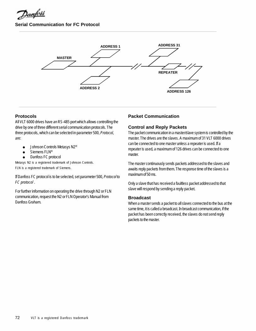
72 VLT is a registered Danfoss trademark
Serial Communication for FC Protocol
ProtocolsAll VLT 6000 drives have an RS-485 port which allows controlling thedrive by one of three different serial communication protocols. Thethree protocols, which can be selected in parameter 500, Protocol,are:
Johnson Controls Metasys N2®
Siemens FLN®
Danfoss FC protocolMetasys N2 is a registered trademark of Johnson Controls.
FLN is a registered trademark of Siemens.
If Danfoss FC protocol is to be selected, set parameter 500, Protocol toFC protocol .
For further information on operating the drive through N2 or FLNcommunication, request the N2 or FLN Operator’s Manual fromDanfoss Graham.
Packet Communication
Control and Reply PacketsThe packet communication in a master/slave system is controlled by themaster. The drives are the slaves. A maximum of 31 VLT 6000 drivescan be connected to one master unless a repeater is used. If arepeater is used, a maximum of 126 drives can be connected to onemaster.
The master continuously sends packets addressed to the slaves andawaits reply packets from them. The response time of the slaves is amaximum of 50 ms.
Only a slave that has received a faultless packet addressed to thatslave will respond by sending a reply packet.
BroadcastWhen a master sends a packet to all slaves connected to the bus at thesame time, it is called a broadcast. In broadcast communication, if thepacket has been correctly received, the slaves do not send replypackets to the master.
ADDRESS 1
MASTER
ADDRESS 126ADDRESS 2
ADDRESS 31
REPEATER
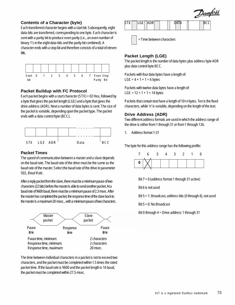
73VLT is a registered Danfoss trademark
Contents of a Character (byte)Each transferred character begins with a start bit. Subsequently, eightdata-bits are transferred, corresponding to one byte. Each character issent with a parity bit to produce even parity (i.e., an even number ofbinary 1’s in the eight data-bits and the parity bit combined). Acharacter ends with a stop bit and therefore consists of a total of elevenbits.
Start 0 1 2 3 4 5 6 7 Even Stopbit Parity Bit
Packet Buildup with FC ProtocolEach packet begins with a start character (STX) = 02 Hex, followed bya byte that gives the packet length (LGE) and a byte that gives thedrive address (ADR). Next a number of data bytes is sent. The size ofthe packet is variable, depending upon the packet type. The packetends with a data control byte (BCC).
STX LGE ADR Data BCC
Packet TimesThe speed of communication between a master and a slave dependson the baud rate. The baud rate of the drive must be the same as thebaud rate of the master. Select the baud rate of the drive in parameter502, Baud Rate.
After a reply packet from the slave, there must be a minimum pause of twocharacters (22 bits) before the master is able to send another packet. At abaud rate of 9600 baud, there must be a minimum pause of 2.3 msec. Afterthe master has completed the packet, the response time of the slave back tothe master is a maximum 20 msec., with a minimum pause of two characters.
Pause time, minimum: 2 charactersResponse time, minimum: 2 charactersResponse time, maximum: 20 msec.
The time between individual characters in a packet is not to exceed twocharacters, and the packet must be completed within 1.5 times the ratedpacket time. If the baud rate is 9600 and the packet length is 16 baud,the packet must be completed within 27.5 msec.
STX LGE ADR DATA BCC
= Time between characters
Packet Length (LGE)The packet length is the number of data bytes plus address byte ADRplus data control byte BCC.
Packets with four data bytes have a length of:LGE = 4 + 1 + 1 = 6 bytes
Packets with twelve data bytes have a length of:LGE = 12 + 1 + 1 = 14 bytes
Packets that contain text have a length of 10+n bytes. Ten is the fixedcharacters, while ‘n’ is variable, depending on the length of the text.
Drive Address (ADR)Two different address formats are used in which the address range ofthe drive is either from 1 through 31 or from 1 through 126.
1. Address format 1-31
The byte for this address range has the following profile:
7 6 5 4 3 2 1 0
0
Bit 7 = 0 (address format 1 through 31 active)
Bit 6 is not used
Bit 5 = 1: Broadcast, address bits (0 through 4), not used
Bit 5 = 0: No Broadcast
Bit 0 through 4 = Drive address 1 through 31
- - - - - -
- - - - - -
Pausetime
Responsetime
Pausetime
Master packet
Slave packet
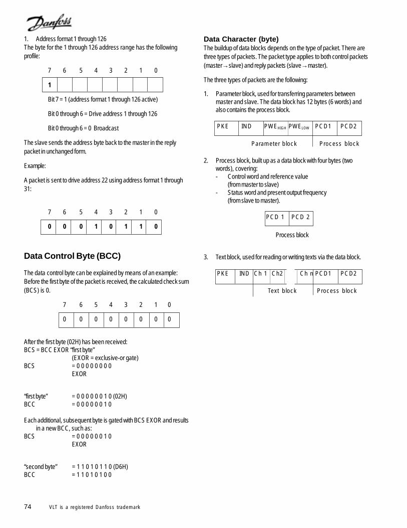
74 VLT is a registered Danfoss trademark
Data Character (byte)The buildup of data blocks depends on the type of packet. There arethree types of packets. The packet type applies to both control packets(master→slave) and reply packets (slave→master).
The three types of packets are the following:
1. Parameter block, used for transferring parameters betweenmaster and slave. The data block has 12 bytes (6 words) andalso contains the process block.
PKE IND PWEHIGH PWELOW PCD1 PCD2
Parameter block Process block
2. Process block, built up as a data block with four bytes (twowords), covering:- Control word and reference value
(from master to slave)- Status word and present output frequency
(from slave to master).
PCD 1 PCD 2
Process block
3. Text block, used for reading or writing texts via the data block.
PKE IND Ch 1 Ch2 Ch n PCD1 PCD2
Text block Process block
1. Address format 1 through 126The byte for the 1 through 126 address range has the followingprofile:
7 6 5 4 3 2 1 0
1
Bit 7 = 1 (address format 1 through 126 active)
Bit 0 through 6 = Drive address 1 through 126
Bit 0 through 6 = 0 Broadcast
The slave sends the address byte back to the master in the replypacket in unchanged form.
Example:
A packet is sent to drive address 22 using address format 1 through31:
7 6 5 4 3 2 1 0
0 0 0 1 0 1 1 0
Data Control Byte (BCC)
The data control byte can be explained by means of an example:Before the first byte of the packet is received, the calculated check sum(BCS) is 0.
7 6 5 4 3 2 1 0
0 0 0 0 0 0 0 0
After the first byte (02H) has been received:BCS = BCC EXOR “first byte”
(EXOR = exclusive-or gate)BCS = 0 0 0 0 0 0 0 0
EXOR
“first byte” = 0 0 0 0 0 0 1 0 (02H)BCC = 0 0 0 0 0 0 1 0
Each additional, subsequent byte is gated with BCS EXOR and resultsin a new BCC, such as:
BCS = 0 0 0 0 0 0 1 0EXOR
“second byte” = 1 1 0 1 0 1 1 0 (D6H)BCC = 1 1 0 1 0 1 0 0
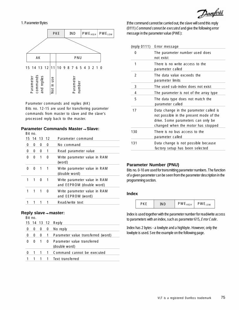
75VLT is a registered Danfoss trademark
1. Parameter Bytes
15 14 13 12 11 10 9 8 7 6 5 4 3 2 1 0
Parameter commands and replies (AK)Bits no. 12-15 are used for transferring parametercommands from master to slave and the slave'sprocessed reply back to the master.
PNU
PKE
AK
Par
amet
erco
mm
and
san
d re
plie
s
Par
amet
ernu
mbe
r
Not
in u
se
IND PWEHIGH PWELOW
If the command cannot be carried out, the slave will send this reply(0111) Command cannot be executed and give the following errormessage in the parameter value (PWE):
(reply 0111) Error message
0 The parameter number used doesnot exist
1 There is no write access to theparameter called
2 The data value exceeds theparameter limits
3 The used sub-index does not exist
4 The parameter is not of the array type
5 The data type does not match theparameter called
17 Data change in the parameter called isnot possible in the present mode of thedrive. Some parameters can only bechanged when the motor has stopped
130 There is no bus access to theparameter called
131 Data change is not possible becausefactory setup has been selected
Parameter Commands Master→→→→→Slave:Bit no.15 14 13 12 Parameter command
0 0 0 0 No command
0 0 0 1 Read parameter value
0 0 1 0 Write parameter value in RAM(word)
0 0 1 1 Write parameter value in RAM(double word)
1 1 0 1 Write parameter value in RAMand EEPROM (double word)
1 1 1 0 Write parameter value in RAMand EEPROM (word)
1 1 1 1 Read/write text
Reply slave→→→→→master:Bit no.15 14 13 12 Reply
0 0 0 0 No reply
0 0 0 1 Parameter value transferred (word)
0 0 1 0 Parameter value transferred(double word)
0 1 1 1 Command cannot be executed
1 1 1 1 Text transferred
Parameter Number (PNU)Bits no. 0-10 are used for transmitting parameter numbers. The functionof a given parameter can be seen from the parameter description in theprogramming section.
Index
Index is used together with the parameter number for read/write accessto parameters with an index, such as parameter 615, Error Code.
Index has 2 bytes - a lowbyte and a highbyte. However, only thelowbyte is used. See the example on the following page.
PKE IND PWEHIGH PWELOW
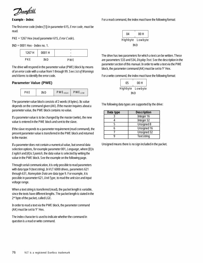
76 VLT is a registered Danfoss trademark
For a read command, the index must have the following format:
04 00 H
The drive has two parameters for which a text can be written. Theseare parameters 533 and 534, Display Text. See the description in theparameter section of this manual. In order to write a text via the PWEblock, the parameter command (AK) must be set to 'F' Hex.
For a write command, the index must have the following format:
05 00 H
The following data types are supported by the drive:
Data type Description3 Integer 164 Integer 325 Unsigned 86 Unsigned 167 Unsigned 329 Text string
Unsigned means there is no sign included in the packet.
Example - Index:
The first error code (index [1]) in parameter 615, Error code, must beread.
PKE = 1267 Hex (read parameter 615, Error Code).
IND = 0001 Hex - Index no. 1.
1267 H 0001 H
The drive will respond in the parameter value (PWE) block by meansof an error code with a value from 1 through 99. See List of Warningsand Alarms to identify the error code.
Parameter Value (PWE)
The parameter value block consists of 2 words (4 bytes). Its valuedepends on the command given (AK). If the master inquires about aparameter value, the PWE block contains no value.
If a parameter value is to be changed by the master (write), the newvalue is entered in the PWE block and sent to the slave.
If the slave responds to a parameter requirement (read command), thepresent parameter value is transferred in the PWE block and returnedto the master.
If a parameter does not contain a numerical value, but several dataselection options, for example parameter 001, Language, where [0] isEnglish and [4] is Spanish, the data value is selected by writing thevalue in the PWE block. See the example on the following page.
Through serial communication, it is only possible to read parameterswith data type 9 (text string). In VLT 6000 drives, parameters 621through 631, Nameplate Data are data type 9. For example, it ispossible in parameter 621, Unit Type, to read the unit size and inputvoltage range.
When a text string is transferred (read), the packet length is variable,since the texts have different lengths. The packet length is stated in the2nd byte of the packet, called LGE.
In order to read a text via the PWE block, the parameter command(AK) must be set to ‘F’ Hex.
The index character is used to indicate whether the command inquestion is a read or write command.
PKE IND PWEHIGH PWELOW
PKE IND PWE
LowbyteHighbyte
IND
LowbyteHighbyteIND
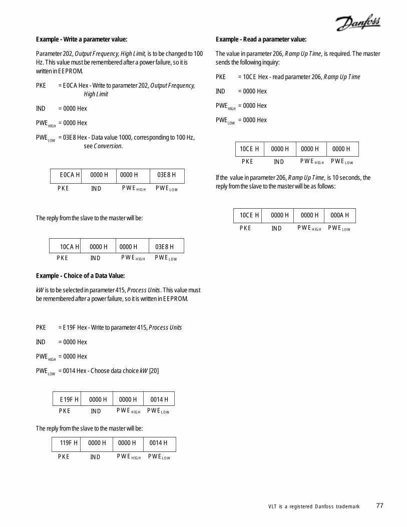
77VLT is a registered Danfoss trademark
PKE IND PWEHIGH PWELOW
PKE IND PWEHIGH PWELOW
PKE IND PWEHIGH PWELOW
PKE IND PWEHIGH PWELOW
Example - Write a parameter value:
Parameter 202, Output Frequency, High Limit, is to be changed to 100Hz. This value must be remembered after a power failure, so it iswritten in EEPROM.
PKE = E0CA Hex - Write to parameter 202, Output Frequency,High Limit
IND = 0000 Hex
PWEHIGH
= 0000 Hex
PWELOW
= 03E8 Hex - Data value 1000, corresponding to 100 Hz,see Conversion.
E0CA H 0000 H 0000 H 03E8 H
The reply from the slave to the master will be:
10CA H 0000 H 0000 H 03E8 H
Example - Choice of a Data Value:
kW is to be selected in parameter 415, Process Units. This value mustbe remembered after a power failure, so it is written in EEPROM.
PKE = E19F Hex - Write to parameter 415, Process Units
IND = 0000 Hex
PWEHIGH
= 0000 Hex
PWELOW
= 0014 Hex - Choose data choice kW [20]
E19F H 0000 H 0000 H 0014 H
The reply from the slave to the master will be:
119F H 0000 H 0000 H 0014 H
PKE IND PWEHIGH PWELOW
PKE IND PWEHIGH PWELOW
Example - Read a parameter value:
The value in parameter 206, Ramp Up Time, is required. The mastersends the following inquiry:
PKE = 10CE Hex - read parameter 206, Ramp Up Time
IND = 0000 Hex
PWEHIGH
= 0000 Hex
PWELOW
= 0000 Hex
10CE H 0000 H 0000 H 0000 H
If the value in parameter 206, Ramp Up Time, is 10 seconds, thereply from the slave to the master will be as follows:
10CE H 0000 H 0000 H 000A H
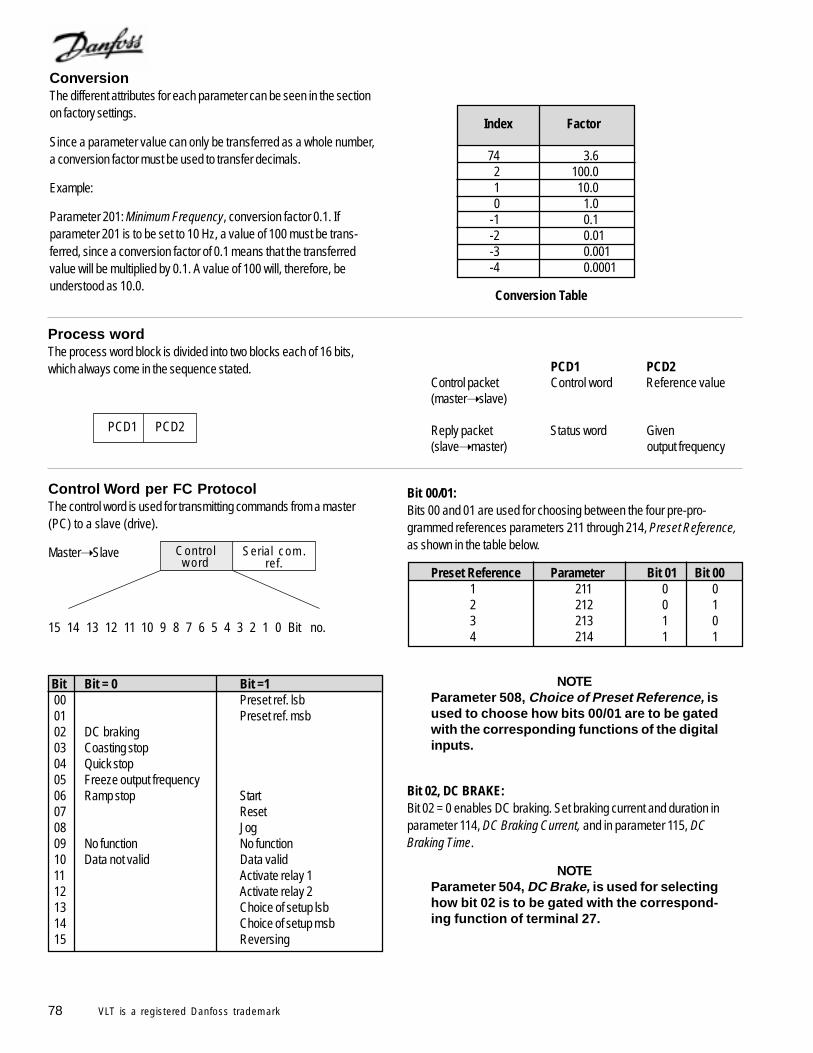
78 VLT is a registered Danfoss trademark
PCD1 PCD2Control packet Control word Reference value(master slave)
Reply packet Status word Given(slave master) output frequency
Process wordThe process word block is divided into two blocks each of 16 bits,which always come in the sequence stated.
PCD1 PCD2
Index Factor
74 3.62 100.01 10.00 1.0
-1 0.1-2 0.01-3 0.001-4 0.0001
ConversionThe different attributes for each parameter can be seen in the sectionon factory settings.
Since a parameter value can only be transferred as a whole number,a conversion factor must be used to transfer decimals.
Example:
Parameter 201: Minimum Frequency, conversion factor 0.1. Ifparameter 201 is to be set to 10 Hz, a value of 100 must be trans-ferred, since a conversion factor of 0.1 means that the transferredvalue will be multiplied by 0.1. A value of 100 will, therefore, beunderstood as 10.0.
Control Word per FC ProtocolThe control word is used for transmitting commands from a master(PC) to a slave (drive).
Master Slave
15 14 13 12 11 10 9 8 7 6 5 4 3 2 1 0 Bit no.
Bit Bit = 0 Bit =1 00 Preset ref. lsb 01 Preset ref. msb 02 DC braking 03 Coasting stop 04 Quick stop 05 Freeze output frequency 06 Ramp stop Start 07 Reset 08 Jog 09 No function No function 10 Data not valid Data valid 11 Activate relay 1 12 Activate relay 2 13 Choice of setup lsb 14 Choice of setup msb 15 Reversing
Bit 00/01:Bits 00 and 01 are used for choosing between the four pre-pro-grammed references parameters 211 through 214, Preset Reference,as shown in the table below.
Preset Reference Parameter Bit 01 Bit 001 211 0 02 212 0 13 213 1 04 214 1 1
NOTEParameter 508, Choice of Preset Reference, isused to choose how bits 00/01 are to be gatedwith the corresponding functions of the digitalinputs.
Bit 02, DC BRAKE:Bit 02 = 0 enables DC braking. Set braking current and duration inparameter 114, DC Braking Current, and in parameter 115, DCBraking Time.
NOTEParameter 504, DC Brake, is used for selectinghow bit 02 is to be gated with the correspond-ing function of terminal 27.
Serial com.ref.
Controlword
Conversion Table
79VLT is a registered Danfoss trademark
Bit 03, Coasting Stop:Bit 03 = 0 means that the drive will coast to a stop.Bit 03 = 1 means that the drive is able to start the motor, provided theother conditions for starting are fulfilled.
NOTEIn parameter 503, Coasting Stop, the choice ismade of how bit 03 is to be gated with the cor-responding function of terminal 27.
Bit 04, Quick Stop:Bit 04 = 0 leads to a stop in which the motor speed is ramped down to astop as set in parameter 207, Ramp Down Time.
Bit 05, Freeze Output Frequency:Bit 05 = 0 means that the given output frequency is frozen. The frozenoutput frequency can now only be changed with the digital inputsprogrammed for Speed Up and Speed Down.
NOTEIf Freeze Output is active, drive cannot bestopped via Bit 06, Start, or through terminal18. Drive can only be stopped in following ways: Bit 03, Coasting Stop Terminal 27 Bit 02, DC Braking Terminal 19 programmed for DC Braking
Bit 06, Ramp Stop/Start:Bit 06 = 0 leads to a stop in which the motor speed is ramped down tostop through parameter 207, Ramp Down Time.Bit 06 = 1 means that the drive is able to start the motor, provided theother conditions for starting are fulfilled.
NOTEParameter 505, Start, determines how bit 06,Ramp Stop/Start, is gated and correspondingfunction of terminal 18.
Bit 07, Reset:Bit 07 = 0 leads to no reset.Bit 07 = 1 means that a trip is reset.Reset is activated on the leading edge of the signal, at the time thesignal changes from logic 0 to logic 1.
Bit 08, Jog:Bit 08 = 1 means that the output frequency is determined by parameter209, Jog Frequency.
Bit 09, No function:Bit 09 has no function.
Bit 10, Data Not Valid/Data Valid:Used for telling the drive whether the control is to be used or ignored.Bit 10 = 0 means that the control word is ignored.Bit 10 = 1 means that the control word is used. This function is relevantbecause the control word is always contained in the packet, regardlessof the type of packet used. Therefore it is possible to disconnect thecontrol word if it is not to be used in connection with updating or readingof parameters.
Bit 11, Relay 1:Bit 11 = 0 Relay 1 is not activated.Bit 11 = 1 Relay 1 is activated, provided Control Word Bits 11/12 hasbeen selected in parameter 323, Relay Outputs.
Bit 12, Relay 2:Bit 12 = 0 Relay 2 is not activated.Bit 12 = 1 Relay 2 is activated, provided Control Word Bits 11/12 hasbeen selected in parameter 326, Relay Outputs.
NOTEIf time-out period set in parameter 556, Bus TimeInterval Function, is exceeded, relays 1 and 2will have voltage removed if activated via serialcommunication.
Bits 13/14, Choice of Setup:Bits 13 and 14 are used to choose among the four menu setups inaccordance with the following table:
Setup Bit 14 Bit 131 0 02 0 13 1 04 1 1
This function is only possible if Multi-setup has been selected inparameter 004.
NOTEIn parameter 507, Choice of Setup, a choice ismade of how bits 13/14 are gated with corre-sponding function of digital inputs.
Bit 15, No function/reversing:Bit 15 = 0 leads to no reversingBit 15 = 1 leads to reversingIn the factory setting, reversing has been selected as digital inparameter 506, Reversing. Bit 15 will only allow reversing, if bus orlogic or has been selected, or logic and has been selected and asignal is present at terminal 19.
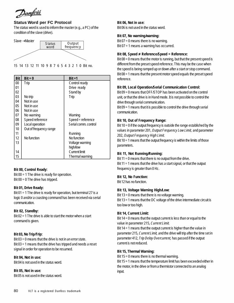
80 VLT is a registered Danfoss trademark
Status Word per FC ProtocolThe status word is used to inform the master (e.g., a PC) of thecondition of the slave (drive).
Slave Master
15 14 13 12 11 10 9 8 7 6 5 4 3 2 1 0 Bit no.
Bit Bit = 0 Bit =1 00 Trip Control ready 01 Drive ready 02 Stand by 03 No trip Trip 04 Not in use 05 Not in use 06 Not in use 07 No warning Warning 08 Speed reference Speed = reference 09 Local operation Serial comm. control 10 Out of frequency range 11 Running 12 No function No function 13 Voltage warning
high/low 14 Current limit 15 Thermal warning
Bit 00, Control Ready:Bit 00 = 1 The drive is ready for operation.Bit 00 = 0 The drive has tripped.
Bit 01, Drive Ready:Bit 01 = 1 The drive is ready for operation, but terminal 27 is alogic 0 and/or a coasting command has been received via serialcommunication.
Bit 02, Standby:Bit 02 = 1 The drive is able to start the motor when a startcommand is given.
Bit 03, No Trip/Trip:Bit 03 = 0 means that the drive is not in an error state.Bit 03 = 1 means that the drive has tripped and needs a resetsignal in order for operation to be resumed.
Bit 04, Not in use:Bit 04 is not used in the status word.
Bit 05, Not in use:Bit 05 is not used in the status word.
Bit 06, Not in use:Bit 06 is not used in the status word.
Bit 07, No warning/warning:Bit 07 = 0 means there is no warning.Bit 07 = 1 means a warning has occurred.
Bit 08, Speed ≠≠≠≠≠ Reference/Speed = Reference:Bit 08 = 0 means that the motor is running, but that the present speed isdifferent from the preset speed reference. This may be the case whenthe speed is being ramped up or down after a start or stop command.Bit 08 = 1 means that the present motor speed equals the preset speedreference.
Bit 09, Local Operation/Serial Communication Control:Bit 09 = 0 means that OFF/STOP has been activated on the controlunit, or that the drive is in Hand mode. It is not possible to control thedrive through serial communication.Bit 09 = 1 means that it is possible to control the drive through serialcommunication.
Bit 10, Out of Frequency Range:Bit 10 = 0 if the output frequency is outside the range established by thevalues in parameter 201, Output Frequency Low Limit, and parameter202, Output Frequency High Limit.Bit 10 = 1 means that the output frequency is within the limits of thoseparameters.
Bit 11, Not Running/Running:Bit 11 = 0 means that there is no output from the drive.Bit 11 = 1 means that the drive has a start signal, or that the outputfrequency is greater than 0 Hz.
Bit 12, No Function:Bit 12 has no function.
Bit 13, Voltage Warning High/Low:Bit 13 = 0 means that there is no voltage warning.Bit 13 = 1 means that the DC voltage of the drive intermediate circuit istoo low or too high.
Bit 14, Current Limit:Bit 14 = 0 means that the output current is less than or equal to thevalue in parameter 215, Current Limit.Bit 14 = 1 means that the output current is higher than the value inparameter 215, Current Limit, and the drive will trip after the time set inparameter 412, Trip Delay Overcurrent, has passed if the outputcurrent is not reduced.
Bit 15, Thermal Warning:Bit 15 = 0 means there is no thermal warning.Bit 15 = 1 means that the temperature limit has been exceeded either inthe motor, in the drive or from a thermistor connected to an analoginput.
Outputfrequency
Statusword
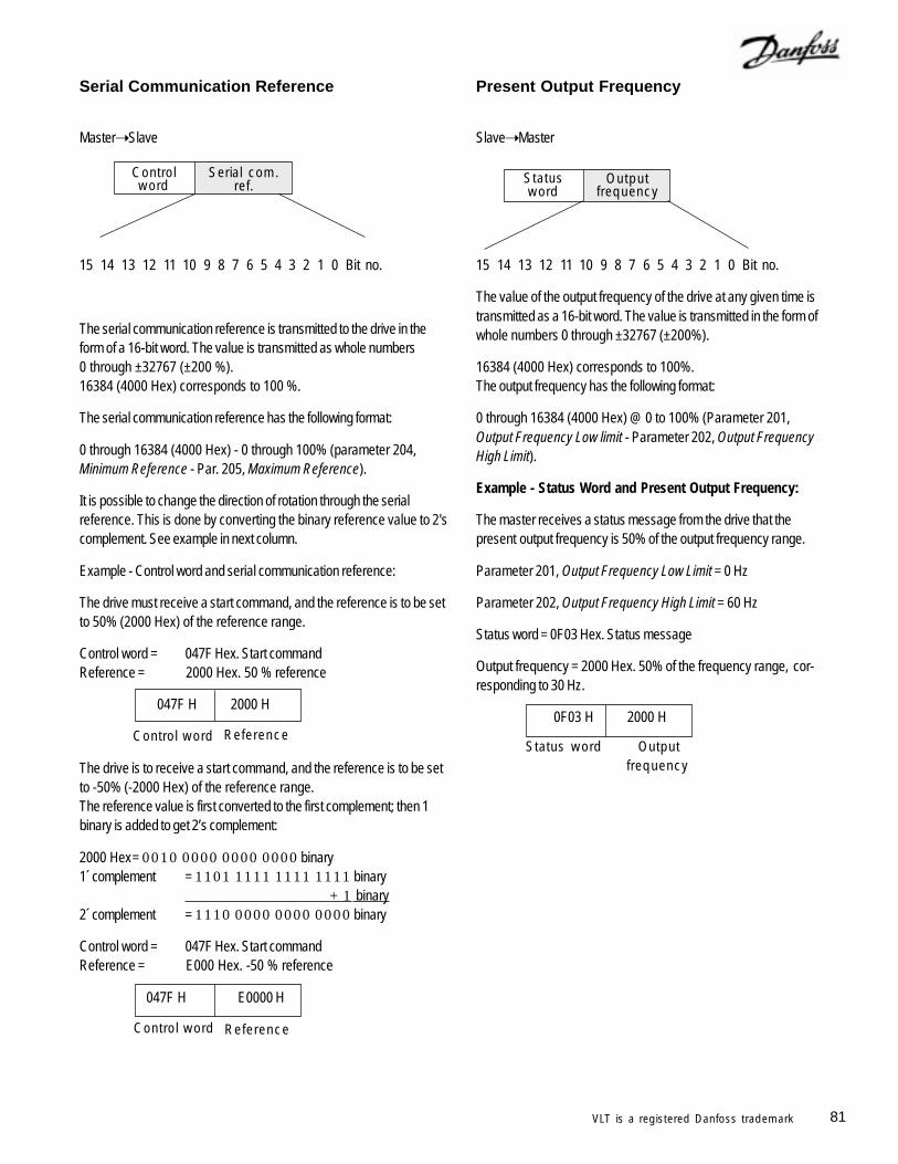
81VLT is a registered Danfoss trademark
Present Output Frequency
Slave Master
15 14 13 12 11 10 9 8 7 6 5 4 3 2 1 0 Bit no.
The value of the output frequency of the drive at any given time istransmitted as a 16-bit word. The value is transmitted in the form ofwhole numbers 0 through ±32767 (±200%).
16384 (4000 Hex) corresponds to 100%.The output frequency has the following format:
0 through 16384 (4000 Hex) @ 0 to 100% (Parameter 201,Output Frequency Low limit - Parameter 202, Output FrequencyHigh Limit).
Example - Status Word and Present Output Frequency:
The master receives a status message from the drive that thepresent output frequency is 50% of the output frequency range.
Parameter 201, Output Frequency Low Limit = 0 Hz
Parameter 202, Output Frequency High Limit = 60 Hz
Status word = 0F03 Hex. Status message
Output frequency = 2000 Hex. 50% of the frequency range, cor-responding to 30 Hz.
0F03 H 2000 H
Outputfrequency
Status word
Outputfrequency
Statusword
Serial Communication Reference
Master Slave
15 14 13 12 11 10 9 8 7 6 5 4 3 2 1 0 Bit no.
The serial communication reference is transmitted to the drive in theform of a 16-bit word. The value is transmitted as whole numbers0 through ±32767 (±200 %).16384 (4000 Hex) corresponds to 100 %.
The serial communication reference has the following format:
0 through 16384 (4000 Hex) - 0 through 100% (parameter 204,Minimum Reference - Par. 205, Maximum Reference).
It is possible to change the direction of rotation through the serialreference. This is done by converting the binary reference value to 2'scomplement. See example in next column.
Example - Control word and serial communication reference:
The drive must receive a start command, and the reference is to be setto 50% (2000 Hex) of the reference range.
Control word = 047F Hex. Start commandReference = 2000 Hex. 50 % reference
047F H 2000 H
The drive is to receive a start command, and the reference is to be setto -50% (-2000 Hex) of the reference range.The reference value is first converted to the first complement; then 1binary is added to get 2’s complement:
2000 Hex= 0010 0000 0000 0000 binary1´ complement = 1101 1111 1111 1111 binary
+ 1 binary2´ complement = 1110 0000 0000 0000 binary
Control word = 047F Hex. Start commandReference = E000 Hex. -50 % reference
047F H E0000 H
Serial com.ref.
Controlword
ReferenceControl word
ReferenceControl word
82 VLT is a registered Danfoss trademark
Serial CommunicationParameters 500 through 566This parameter group sets up the drive for serial communication.
There is a choice of three protocols: FC (VLT protocol), JohnsonControls Metasys N2 and Siemens FLN. In order to use serialcommunication to control the drive, address and baud rate must alwaysbe set. In addition to controlling the drive, operational data from thedrive including reference, feedback, motor temperature and others canbe read through serial communication.
500 Protocol(PROTOCOL)
Value: FC protocol (FC PROTOCOL) [0]
Metasys N2 (METASYS N2) [1]Landis & Staefa FLN (FLN) [2]
Function:There is a choice of three different protocols.
Description of choice:Select the required control word protocol.
501 Address(ADDRESS)
Value:Parameter 500 Protocol = FC protocol
0 through 126 1Parameter 500 Protocol = Metasys N2
1 through 255 1Parameter 500 Protocol = FLN
0 through 98 1Function:
In this parameter it is possible to allocate an address in a serialcommunication network to each drive.
Description of choice:The individual drive must be given a unique address. If the number ofdrives exceeds 31, a repeater must be used. Parameter 501, Address,cannot be chosen via serial communication but is set via the keypad.
502 Baud Rate(BAUDRATE)
Value:300 Baud (300 BAUD) [0]600 Baud (600 BAUD) [1]1200 Baud (1200 BAUD) [2]2400 Baud (2400 BAUD) [3]4800 Baud (4800 BAUD) [4]
9600 Baud (9600 BAUD) [5]Function:
In this parameter, the speed at which data is transmitted via serialcommunication is programmed. Baud rate is defined as the number ofbits transmitted per second.
Description of choice:The transmission speed of the drive must be set at a value thatcorresponds to the transmission speed of the master. Parameter 502,Baud Rate, cannot be selected through serial communication; it must beset by the keypad. The data transmission time itself, which is determinedby the baud rate selected, is only part of the total communication time.
503 Coasting Stop(COASTING)
Value:Digital input (DIGITAL INPUT) [0]Serial communication (SERIAL PORT) [1]Logic and (LOGIC AND) [2]
Logic or (LOGIC OR) [3]Function:
In parameters 503 through 508, a choice can be made to control thedrive via the digital inputs and/or by serial communication.
If Digital input is selected, the command can only be carried outthrough digital input.
If Serial communication is selected, the command can only be carriedout through serial communication.
If Logic and is selected, the command must be by both serial communi-cation and a digital input.
If Logic or is selected, the command can be made by either digital orserial communication.
Description of choice:The tables below show whether the motor is running or coasting whenDigital Input, Serial Communication, Logic and or Logic or has beenselected.
NOTETerminal 27 and bit 03 of control word are activewhen logic 0 is selected.
Indicates default parameter. Depending upon the application, the drive may be delivered with other parameters selected.
Digital Input Serial CommunicationSerial Serial
Term. 27 Comm. Function Term. 27 Comm. Function0 0 Coasting 0 0 Coasting0 1 Coasting 0 1 Motor run1 0 Motor run 1 0 Coasting1 1 Motor run 1 1 Motor run
Logic and Logic orSerial Serial
Term. 27 Comm. Function Term. 27 Comm. Function0 0 Coasting 0 0 Coasting0 1 Motor run 0 1 Coasting1 0 Motor run 1 0 Coasting1 1 Motor run 1 1 Motor run
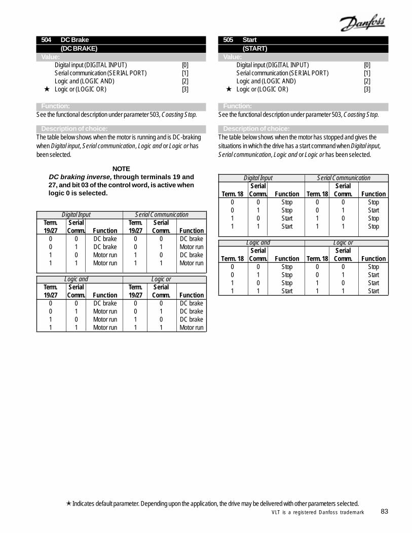
83VLT is a registered Danfoss trademark
505 Start(START)
Value:Digital input (DIGITAL INPUT) [0]Serial communication (SERIAL PORT) [1]Logic and (LOGIC AND) [2]
Logic or (LOGIC OR) [3]
Function:See the functional description under parameter 503, Coasting Stop.
Description of choice:The table below shows when the motor has stopped and gives thesituations in which the drive has a start command when Digital input,Serial communication, Logic and or Logic or has been selected.
504 DC Brake(DC BRAKE)
Value:Digital input (DIGITAL INPUT) [0]Serial communication (SERIAL PORT) [1]Logic and (LOGIC AND) [2]
Logic or (LOGIC OR) [3]
Function:See the functional description under parameter 503, Coasting Stop.
Description of choice:The table below shows when the motor is running and is DC-brakingwhen Digital input, Serial communication, Logic and or Logic or hasbeen selected.
NOTEDC braking inverse, through terminals 19 and27, and bit 03 of the control word, is active whenlogic 0 is selected.
Indicates default parameter. Depending upon the application, the drive may be delivered with other parameters selected.
Digital Input Serial CommunicationTerm. Serial Term. Serial19/27 Comm. Function 19/27 Comm. Function
0 0 DC brake 0 0 DC brake0 1 DC brake 0 1 Motor run1 0 Motor run 1 0 DC brake1 1 Motor run 1 1 Motor run
Logic and Logic orTerm. Serial Term. Serial19/27 Comm. Function 19/27 Comm. Function
0 0 DC brake 0 0 DC brake0 1 Motor run 0 1 DC brake1 0 Motor run 1 0 DC brake1 1 Motor run 1 1 Motor run
Digital Input Serial CommunicationSerial Serial
Term. 18 Comm. Function Term. 18 Comm. Function0 0 Stop 0 0 Stop0 1 Stop 0 1 Start1 0 Start 1 0 Stop1 1 Start 1 1 Stop
Logic and Logic orSerial Serial
Term. 18 Comm. Function Term. 18 Comm. Function0 0 Stop 0 0 Stop0 1 Stop 0 1 Start1 0 Stop 1 0 Start1 1 Start 1 1 Start
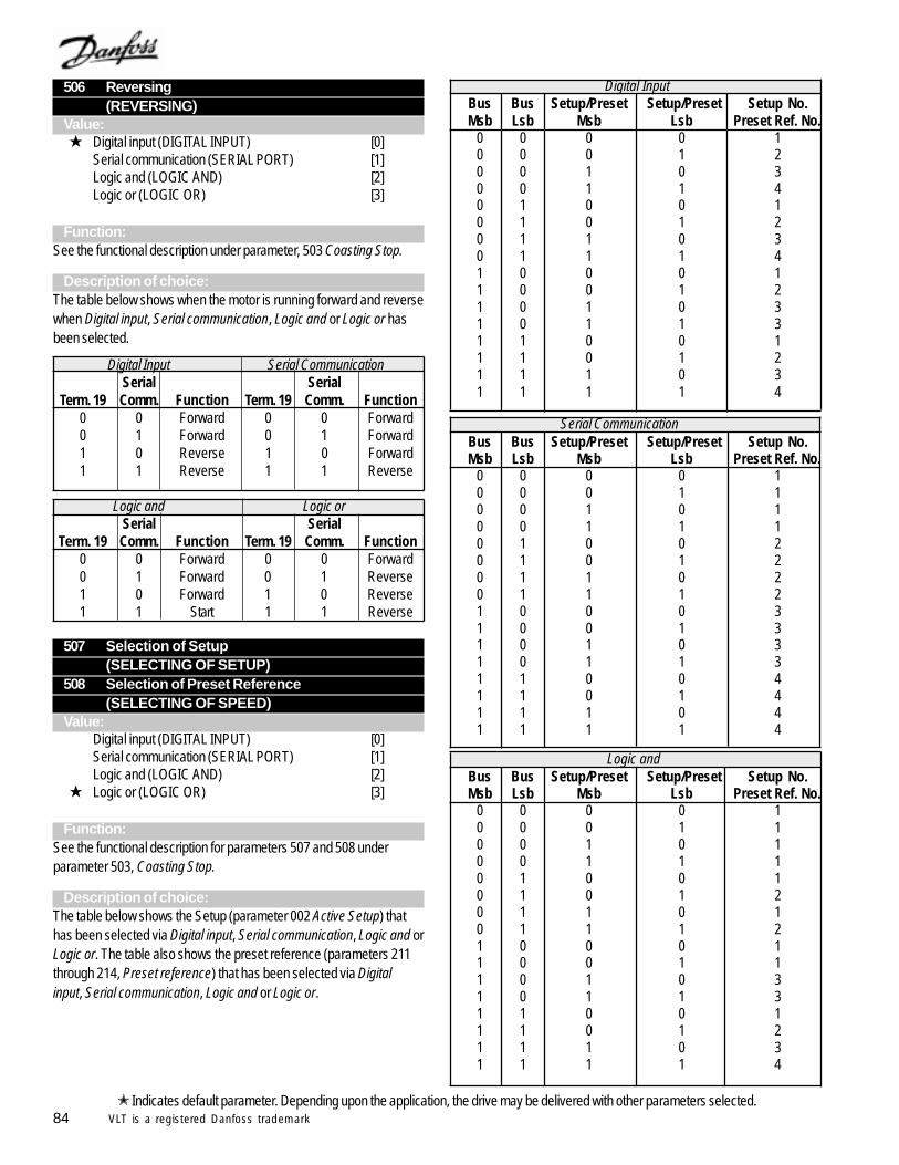
84 VLT is a registered Danfoss trademark
Bus Bus Setup/Preset Setup/Preset Setup No.Msb Lsb Msb Lsb Preset Ref. No.
0 0 0 0 10 0 0 1 10 0 1 0 10 0 1 1 10 1 0 0 20 1 0 1 20 1 1 0 20 1 1 1 21 0 0 0 31 0 0 1 31 0 1 0 31 0 1 1 31 1 0 0 41 1 0 1 41 1 1 0 41 1 1 1 4
507 Selection of Setup(SELECTING OF SETUP)
508 Selection of Preset Reference(SELECTING OF SPEED)
Value:Digital input (DIGITAL INPUT) [0]Serial communication (SERIAL PORT) [1]Logic and (LOGIC AND) [2]
Logic or (LOGIC OR) [3]
Function:See the functional description for parameters 507 and 508 underparameter 503, Coasting Stop.
Description of choice:The table below shows the Setup (parameter 002 Active Setup) thathas been selected via Digital input, Serial communication, Logic and orLogic or. The table also shows the preset reference (parameters 211through 214, Preset reference) that has been selected via Digitalinput, Serial communication, Logic and or Logic or.
Digital InputBus Bus Setup/Preset Setup/Preset Setup No.Msb Lsb Msb Lsb Preset Ref. No.
0 0 0 0 10 0 0 1 20 0 1 0 30 0 1 1 40 1 0 0 10 1 0 1 20 1 1 0 30 1 1 1 41 0 0 0 11 0 0 1 21 0 1 0 31 0 1 1 31 1 0 0 11 1 0 1 21 1 1 0 31 1 1 1 4
506 Reversing(REVERSING)
Value: Digital input (DIGITAL INPUT) [0]
Serial communication (SERIAL PORT) [1]Logic and (LOGIC AND) [2]Logic or (LOGIC OR) [3]
Function:See the functional description under parameter, 503 Coasting Stop.
Description of choice:The table below shows when the motor is running forward and reversewhen Digital input, Serial communication, Logic and or Logic or hasbeen selected.
Logic andBus Bus Setup/Preset Setup/Preset Setup No.Msb Lsb Msb Lsb Preset Ref. No.
0 0 0 0 10 0 0 1 10 0 1 0 10 0 1 1 10 1 0 0 10 1 0 1 20 1 1 0 10 1 1 1 21 0 0 0 11 0 0 1 11 0 1 0 31 0 1 1 31 1 0 0 11 1 0 1 21 1 1 0 31 1 1 1 4
Indicates default parameter. Depending upon the application, the drive may be delivered with other parameters selected.
Serial Communication
Digital Input Serial CommunicationSerial Serial
Term. 19 Comm. Function Term. 19 Comm. Function0 0 Forward 0 0 Forward0 1 Forward 0 1 Forward1 0 Reverse 1 0 Forward1 1 Reverse 1 1 Reverse
Logic and Logic orSerial Serial
Term. 19 Comm. Function Term. 19 Comm. Function0 0 Forward 0 0 Forward0 1 Forward 0 1 Reverse1 0 Forward 1 0 Reverse1 1 Start 1 1 Reverse
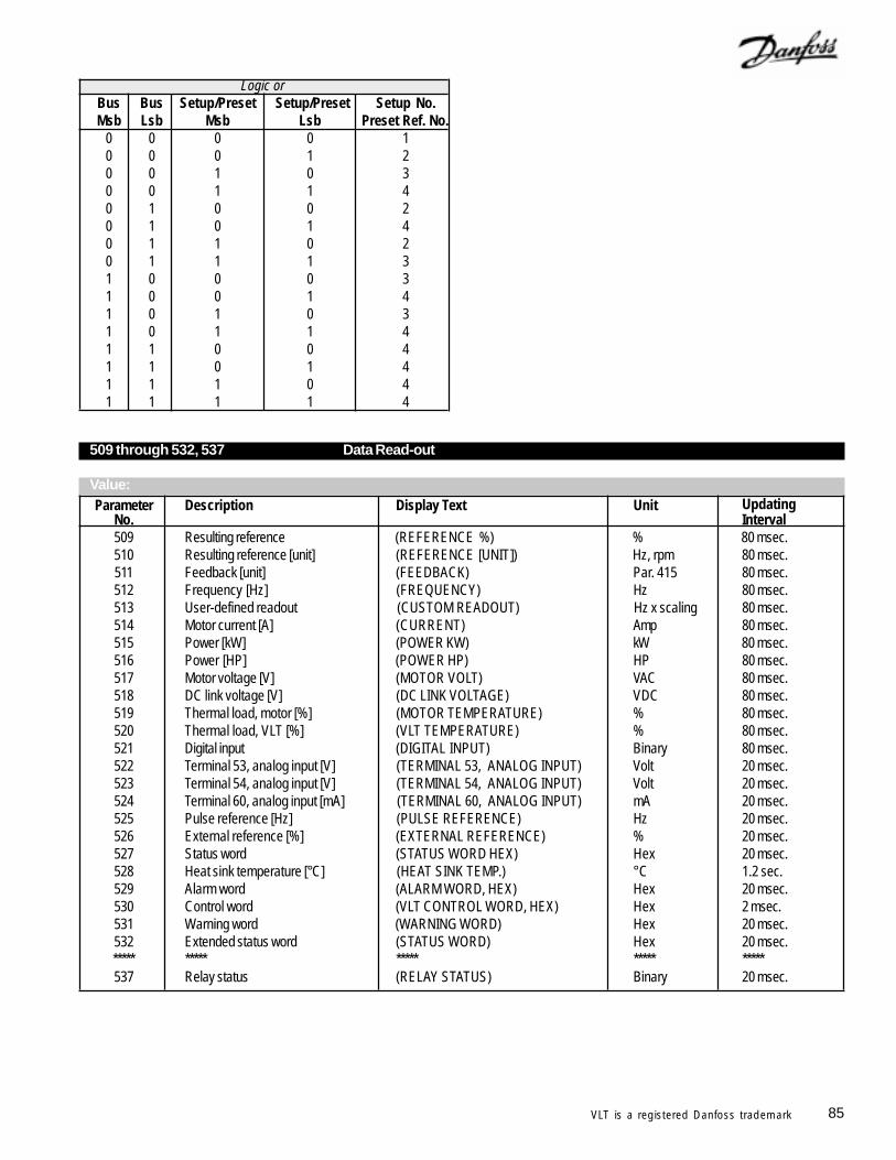
85VLT is a registered Danfoss trademark
509 through 532, 537 Data Read-out
Value:Parameter Description Display Text Unit Updating
No. Interval509 Resulting reference (REFERENCE %) % 80 msec.510 Resulting reference [unit] (REFERENCE [UNIT]) Hz, rpm 80 msec.511 Feedback [unit] (FEEDBACK) Par. 415 80 msec.512 Frequency [Hz] (FREQUENCY) Hz 80 msec.513 User-defined readout (CUSTOM READOUT) Hz x scaling 80 msec.514 Motor current [A] (CURRENT) Amp 80 msec.515 Power [kW] (POWER KW) kW 80 msec.516 Power [HP] (POWER HP) HP 80 msec.517 Motor voltage [V] (MOTOR VOLT) VAC 80 msec.518 DC link voltage [V] (DC LINK VOLTAGE) VDC 80 msec.519 Thermal load, motor [%] (MOTOR TEMPERATURE) % 80 msec.520 Thermal load, VLT [%] (VLT TEMPERATURE) % 80 msec.521 Digital input (DIGITAL INPUT) Binary 80 msec.522 Terminal 53, analog input [V] (TERMINAL 53, ANALOG INPUT) Volt 20 msec.523 Terminal 54, analog input [V] (TERMINAL 54, ANALOG INPUT) Volt 20 msec.524 Terminal 60, analog input [mA] (TERMINAL 60, ANALOG INPUT) mA 20 msec.525 Pulse reference [Hz] (PULSE REFERENCE) Hz 20 msec.526 External reference [%] (EXTERNAL REFERENCE) % 20 msec.527 Status word (STATUS WORD HEX) Hex 20 msec.528 Heat sink temperature [°C] (HEAT SINK TEMP.) °C 1.2 sec.529 Alarm word (ALARM WORD, HEX) Hex 20 msec.530 Control word (VLT CONTROL WORD, HEX) Hex 2 msec.531 Warning word (WARNING WORD) Hex 20 msec.532 Extended status word (STATUS WORD) Hex 20 msec.***** ***** ***** ***** *****537 Relay status (RELAY STATUS) Binary 20 msec.
Logic orBus Bus Setup/Preset Setup/Preset Setup No.Msb Lsb Msb Lsb Preset Ref. No.
0 0 0 0 10 0 0 1 20 0 1 0 30 0 1 1 40 1 0 0 20 1 0 1 40 1 1 0 20 1 1 1 31 0 0 0 31 0 0 1 41 0 1 0 31 0 1 1 41 1 0 0 41 1 0 1 41 1 1 0 41 1 1 1 4
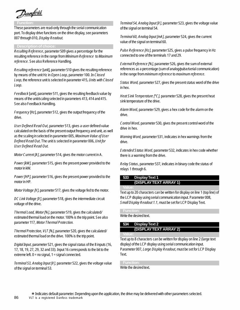
86 VLT is a registered Danfoss trademark
Function:These parameters are read-only through the serial communicationport. To display drive functions on the drive display, see parameters007 through 010, Display Readout.
Description of choice:Resulting Reference, parameter 509 gives a percentage for theresulting reference in the range from Minimum Reference to Maximumreference. See also Reference Handling.
Resulting reference [unit], parameter 510 gives the resulting referenceby means of the unit Hz in Open Loop, parameter 100. In ClosedLoop, the reference unit is selected in parameter 415, Units with ClosedLoop.
Feedback [unit], parameter 511, gives the resulting feedback value bymeans of the unit/scaling selected in parameters 413, 414 and 415.See also Feedback Handling.
Frequency [Hz], parameter 512, gives the output frequency of thedrive.
User Defined Read Out, parameter 513, gives a user defined valuecalculated on the basis of the present output frequency and unit, as wellas the scaling in selected in parameter 005, Maximum Value of UserDefined Read Out. The unit is selected in parameter 006, Unit forUser Defined Read Out.
Motor Current [A], parameter 514, gives the motor current in A.
Power [kW], parameter 515, gives the present power provided to themotor in kW.
Power [HP], parameter 516, gives the present power provided to themotor in HP.
Motor Voltage [V], parameter 517, gives the voltage fed to the motor.
DC Link Voltage [V], parameter 518, gives the intermediate circuitvoltage of the drive.
Thermal Load, Motor [%], parameter 519, gives the calculated/estimated thermal load on the motor. 100% is the trip point. See alsoparameter 117, Motor Thermal Protection.
Thermal Protection, VLT [%], parameter 520, gives the calculated/estimated thermal load on the drive. 100% is the trip point.
Digital Input, parameter 521, gives the signal status of the 8 inputs (16,17, 18, 19, 27, 29, 32 and 33). Input 16 corresponds to the bit to theextreme left. 0 = no signal, 1 = signal connected.
Terminal 53, Analog Input [V], parameter 522, gives the voltage valueof the signal on terminal 53.
Terminal 54, Analog Input [V], parameter 523, gives the voltage valueof the signal on terminal 54.
Terminal 60, Analog Input [mA], parameter 524, gives the currentvalue of the signal on terminal 60.
Pulse Reference [Hz], parameter 525, gives a pulse frequency in Hzconnected to one of the terminals 17 and 29.
External Reference [%], parameter 526, gives the sum of externalreferences as a percentage (sum of analog/pulse/serial communication)in the range from minimum reference to maximum reference.
Status Word, parameter 527, gives the present status word of the drivein hex.
Heat Sink Temperature [°C], parameter 528, gives the present heatsink temperature of the drive.
Alarm Word, parameter 529, gives a hex code for the alarm on thedrive.
Control Word, parameter 530, gives the present control word of thedrive in hex.
Warning Word, parameter 531, indicates in hex warnings from thedrive.
Extended Status Word, parameter 532, indicates in hex code whetherthere is a warning from the drive.
Relay Status, parameter 537, indicates in binary code the status ofrelays 1 through 6.
533 Display Text 1(DISPLAY TEXT ARRAY 1)
Value:Text up to 20 characters can be written for display on line 1 (top line) ofthe LCP display using serial communication input. Parameter 008,Small Display Readout 1.1, must be set for LCP Display Text.
Function:Write the desired text.
534 Display Text 2(DISPLAY TEXT ARRAY 2)
Value:Text up to 8 characters can be written for display on line 2 (large textdisplay) of the LCP display using serial communication input.Parameter 007, Large Display Readout, must be set for LCP DisplayText.
Function:Write the desired text.
Indicates default parameter. Depending upon the application, the drive may be delivered with other parameters selected.
87VLT is a registered Danfoss trademark
536 Bus Feedback 2(BUS FEEDBACK 2)
Value:0 through 16384 decimal (0 through 4000 Hex) 0
Function:Via serial communication, a bus feedback value can be written in thisparameter that will become part of the feedback handling system. BusFeedback 2 will be added to any feedback value on terminal 54.
Description of choice:Write the required bus feedback value via the serial communication.
537 Relay Status(RELAY STATUS)
Value:binary (0 = open, 1 = closed) 0
Description of choice:See Data Read-out for parameters 509 through 532, 537 on previouspage for relay status description.
NOTEParameters 555, Bus Time Interval, and 556, BusTime Interval Function, are only active whenFC Protocol has been selected in parameter500, Protocol.
555 Bus Time Interval(BUS TIME INTERVAL)
Value:1 to 99 sec. 60 sec.
Function:In this parameter, the maximum time allowed between the receipt of twopackets in a row is set. If this time is exceeded, the serial communicationis assumed to have stopped and the choice made in parameter 556,Bus Time Interval Function, will be carried out.
Description of choice:Set the required time.
Indicates default parameter. Depending upon the application, the drive may be delivered with other parameters selected.
556 Bus Time Interval Function(BUS TIME INTERVAL FUNCTION)
Value: Off (NO FUNCTION) [0]
Freeze output (FREEZE OUTPUT) [1]Stop (STOP) [2]Jogging (JOG FREQUENCY) [3]Max. output frequency (MAX FREQUENCY) [4]Stop and trip (STOP AND TRIP) [5]
Function:In this parameter, the required reaction from the drive is selected whenthe time set in parameter 555, Bus Time Interval, has been exceeded.
Description of choice:The output frequency of the drive can be frozen at the present value,frozen as selected in parameter 211, Preset Reference 1, frozen asselected in parameter 202, Maximum Output Frequency, or stop andshow a fault.
560 N2 override release time(N2 OVER.REL.TIME)
Value:1 - 65533 sec. OFF
FunctionThe maximum time is set between the receipt of two N2 messages. If thetime is exceeded, serial communication is assumed stopped. All N2points which are overridden will be released in the following order:
1. Analog outputs2. Binary outputs3. Internal floating points4. Internal integer points5. Internal byte points
N2 point addresses are released in numerical order beginning with 1(or 0).
Description of choice:Set the required time.
535 Bus Feedback 1(BUS FEEDBACK1)
Value:0 through 16384 decimal (0 through 4000 Hex) 0
Function:Via the serial communication port, this parameter allows writing of a busfeedback value which will then form part of the feedback handling. BusFeedback 1 will be added to any feedback value registered on terminal53.
Description of choice:Write the required bus feedback value via serial communication.
88 VLT is a registered Danfoss trademark
Warning Words, Extended Status Word andAlarm WordWarning Word, Extended Status Word and Alarm Word are shown inhex format on the display. If there is more than one warning or alarm,the sum of the warnings or alarms will be shown.
The descriptions of the Extended Status Words, Warning Words andAlarm Words can be read out via the serial bus in parameter 531,Warning Word; 532, Extended Status Word; and 529, Alarm Word.
565 FLN bus time interval(FLN TIME INTER.)
Value:1 - 65534 sec. 60 sec.
FunctionThe maximum time is set between the receipt of two FLN messages. Ifthe time is exceeded, serial communication is assumed stopped andthe required reaction is set in parameter 566, FLN Bus Time IntervalFunction.
Description of choice:Set the required time.
566 FLN bus time interval function(FLN TIME FUNCT.)
Value: Off (NO FUNCTION) [0]
Freeze output (FREEZE OUTPUT) [1]Stop (STOP) [2]Jogging (JOG FREQUENCY) [3]Max. output frequency (MAX.SPEED) [4]Stop and trip (STOP AND TRIP) [5]
FunctionThe required reaction from the adjustable frequency drive is selectedwhen the time set in parameter 565, FLN Bus Time Interval, has beenexceeded.
Description of choice:The output frequency of the adjustable frequency drive can be frozenat the present value at any given time, frozen at parameter 211, PresetReference 1, frozen at parameter 202, Max. Output Frequency, orstop output and show a fault.
Hex Code Extended Status Word (Paramater 532)00000001 Autoramping00000002 Start delay00000004 Sleep boost active00000008 Sleep mode active00000010 Automatic motor adaptation completed00000020 Automatic motor adaptation running00000040 Reverse start (not for VLT 6000)00000080 Normal ramping00000100 Reversing00000200 At reference00000400 Running00000800 Local reference = 0, Remote = 100001000 OFF = 100002000 Hand = 1, Auto = 000004000 Run request00008000 No run permission00010000 Freeze output frequency00020000 Freeze output blocked00040000 Jogging00080000 No jog permission00100000 Stand by00200000 Stopped00400000 DC braking stop00800000 Drive ready01000000 Relay 123 active (Profibus only)02000000 Drive ready04000000 Control ready08000000 Start prevented10000000 Profibus OFF3 active20000000 Profibus OFF2 active40000000 Profibus OFF1 active80000000 Reserved
89VLT is a registered Danfoss trademark
Hex Code Warning Word (Parameter 531)00000001 Reference high00000002 Control card fault00000004 Power card fault00000008 HPFB bus timeout00000010 RS-485 timeout00000020 Overcurrent00000040 Current limit00000080 Motor thermistor00000100 Motor overtemperature00000200 Inverter overtemperature00000400 Undervoltage00000800 Overvoltage00001000 Voltage warning low00002000 Voltage warning high00004000 Input phase fault00008000 Live zero fault00010000 Under 10 Volt (terminal 50)00020000 Reference low00040000 Feedback high00080000 Feedback low00100000 Output current high00200000 Out of frequency range6666600400000 Profibus communication fault00800000 Output current low01000000 Output frequency high02000000 Output frequency low04000000 AMA - motor too small08000000 AMA - motor too big10000000 AMA - check par. 102, 103, or 10520000000 AMA - check par. 102, 104, or 10640000000 Reserved80000000 Reserved
Hex Code Alarm Word (Parameter 529)00000001 Unknown fault00000002 Trip locked00000004 AMA fault00000008 HPFB fault00000010 RS-485 timeout00000020 Short circuit00000040 SMPS fault00000080 Ground fault00000100 Overcurrent00000200 Current limit00000400 Motor thermistor00000800 Motor thermal00001000 Inverter thermal00002000 Undervoltage00004000 Overvoltage00008000 Input phase loss00010000 Live zero fault00020000 Heat sink overtemperature00040000 Motor phase W missing00080000 Motor phase V missing00100000 Motor phase U missing00200000 Profibus communication fault00400000 Inverter fault00800000 Output current low01000000 External fault02000000 Reserved04000000 Reserved08000000 Reserved10000000 Reserved
90 VLT is a registered Danfoss trademark
Service FunctionsParameters 600 through 631
This parameter group contains functions useful for troubleshooting thedrive including operating data, data log and fault log.
It also has information on the nameplate data of the drive.
Function:These parameters can be read out through the serial communicationport as well as on the control panel display.
Description of choice:Parameter 600, Operating Hours
Shows the number of hours the drive has had power applied. Thevalue is saved every hour and when the power is removed. Thisvalue cannot be reset.
Parameter 601, Hours Run
Shows the number of hours the drive has powered the motor. Thisparameter can be reset in parameter 619, Reset of Hours RunCounter. The value is saved every hour and when the power isremoved.
Parameter 602, kWh Counter
Shows the output power of the drive. The calculation is based on themean value in kWh over one hour. This value can be reset usingparameter 618, Reset of kWh Counter.
Parameter 603 Number of Power Ups.
Shows the number of times power has been applied to the drive.
Parameter 604, Number of Overtemperature Trips
Shows the number of overtemperature trips from the heatsink tempera-ture sensor on the drive.
Parameter 605, Number of Overvoltage Trips
Shows the number of overvoltage trips from the sensor of DC linkvoltage of the drive. The count is only taken when Alarm 7 Overvolt-age is activated.
600-605 Operating Data Value:Value:Parameter Description Display Unit RangeNumber Operating Data: Text600 Operating Hours (OPERATING HOURS) Hours 0 through 130,000.0601 Hours Run (RUNNING HOURS) Hours 0 through 130,000.0602 kWh Counter (KWH COUNTER) kWh -603 Number of Power-ups (POWER UPS) Occurences 0 through 9999604 Number of Overtemp Trips (OVER TEMPS) Occurences 0 through 9999605 Number of Overvoltage Trips (OVER VOLTS) Occurences 0 through 9999
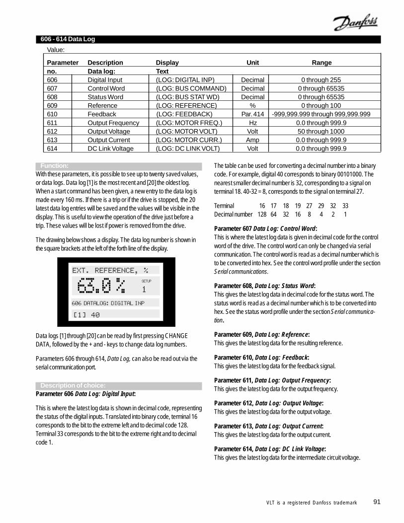
91VLT is a registered Danfoss trademark
Function:With these parameters, it is possible to see up to twenty saved values,or data logs. Data log [1] is the most recent and [20] the oldest log.When a start command has been given, a new entry to the data log ismade every 160 ms. If there is a trip or if the drive is stopped, the 20latest data log entries will be saved and the values will be visible in thedisplay. This is useful to view the operation of the drive just before atrip. These values will be lost if power is removed from the drive.
The drawing below shows a display. The data log number is shown inthe square brackets at the left of the forth line of the display.
Data logs [1] through [20] can be read by first pressing CHANGEDATA, followed by the + and - keys to change data log numbers.
Parameters 606 through 614, Data Log, can also be read out via theserial communication port.
Description of choice:Parameter 606 Data Log: Digital Input:
This is where the latest log data is shown in decimal code, representingthe status of the digital inputs. Translated into binary code, terminal 16corresponds to the bit to the extreme left and to decimal code 128.Terminal 33 corresponds to the bit to the extreme right and to decimalcode 1.
606 - 614 Data Log
Value:
Parameter Description Display Unit Rangeno. Data log: Text606 Digital Input (LOG: DIGITAL INP) Decimal 0 through 255607 Control Word (LOG: BUS COMMAND) Decimal 0 through 65535608 Status Word (LOG: BUS STAT WD) Decimal 0 through 65535609 Reference (LOG: REFERENCE) % 0 through 100610 Feedback (LOG: FEEDBACK) Par. 414 -999,999.999 through 999,999.999611 Output Frequency (LOG: MOTOR FREQ.) Hz 0.0 through 999.9612 Output Voltage (LOG: MOTOR VOLT) Volt 50 through 1000613 Output Current (LOG: MOTOR CURR.) Amp 0.0 through 999.9614 DC Link Voltage (LOG: DC LINK VOLT) Volt 0.0 through 999.9
The table can be used for converting a decimal number into a binarycode. For example, digital 40 corresponds to binary 00101000. Thenearest smaller decimal number is 32, corresponding to a signal onterminal 18. 40-32 = 8, corresponds to the signal on terminal 27.
Terminal 16 17 18 19 27 29 32 33Decimal number 128 64 32 16 8 4 2 1
Parameter 607 Data Log: Control Word:This is where the latest log data is given in decimal code for the controlword of the drive. The control word can only be changed via serialcommunication. The control word is read as a decimal number which isto be converted into hex. See the control word profile under the sectionSerial communications.
Parameter 608, Data Log: Status Word:This gives the latest log data in decimal code for the status word. Thestatus word is read as a decimal number which is to be converted intohex. See the status word profile under the section Serial communica-tion.
Parameter 609, Data Log: Reference:This gives the latest log data for the resulting reference.
Parameter 610, Data Log: Feedback:This gives the latest log data for the feedback signal.
Parameter 611, Data Log: Output Frequency:This gives the latest log data for the output frequency.
Parameter 612, Data Log: Output Voltage:This gives the latest log data for the output voltage.
Parameter 613, Data Log: Output Current:This gives the latest log data for the output current.
Parameter 614, Data Log: DC Link Voltage:This gives the latest log data for the intermediate circuit voltage.
'* )+
'' #, #
-.
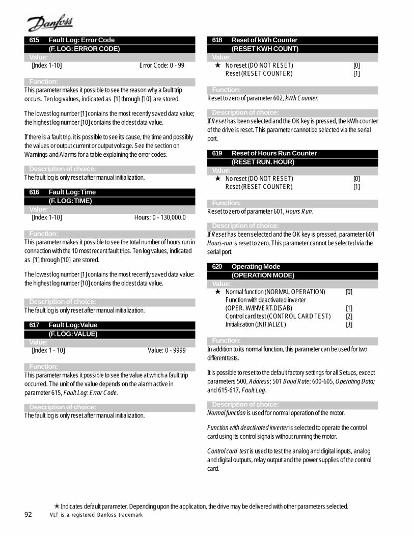
92 VLT is a registered Danfoss trademark
615 Fault Log: Error Code(F. LOG: ERROR CODE)
Value:[Index 1-10] Error Code: 0 - 99
Function:This parameter makes it possible to see the reason why a fault tripoccurs. Ten log values, indicated as [1] through [10] are stored.
The lowest log number [1] contains the most recently saved data value;the highest log number [10] contains the oldest data value.
If there is a fault trip, it is possible to see its cause, the time and possiblythe values or output current or output voltage. See the section onWarnings and Alarms for a table explaining the error codes.
Description of choice:The fault log is only reset after manual initialization.
616 Fault Log: Time(F. LOG: TIME)
Value:[Index 1-10] Hours: 0 - 130,000.0
Function:This parameter makes it possible to see the total number of hours run inconnection with the 10 most recent fault trips. Ten log values, indicatedas [1] through [10] are stored.
The lowest log number [1] contains the most recently saved data value:the highest log number [10] contains the oldest data value.
Description of choice:The fault log is only reset after manual initialization.
617 Fault Log: Value(F. LOG: VALUE)
Value:[Index 1 - 10] Value: 0 - 9999
Function:This parameter makes it possible to see the value at which a fault tripoccurred. The unit of the value depends on the alarm active inparameter 615, Fault Log: Error Code.
Description of choice:The fault log is only reset after manual initialization.
618 Reset of kWh Counter(RESET KWH COUNT)
Value: No reset (DO NOT RESET) [0]
Reset (RESET COUNTER) [1]
Function:Reset to zero of parameter 602, kWh Counter.
Description of choice:If Reset has been selected and the OK key is pressed, the kWh counterof the drive is reset. This parameter cannot be selected via the serialport.
619 Reset of Hours Run Counter(RESET RUN. HOUR)
Value: No reset (DO NOT RESET) [0]
Reset (RESET COUNTER) [1]
Function:Reset to zero of parameter 601, Hours Run.
Description of choice:If Reset has been selected and the OK key is pressed, parameter 601Hours-run is reset to zero. This parameter cannot be selected via theserial port.
620 Operating Mode(OPERATION MODE)
Value: Normal function (NORMAL OPERATION) [0]
Function with deactivated inverter(OPER. W/INVERT.DISAB) [1]Control card test (CONTROL CARD TEST) [2]Initialization (INITIALIZE) [3]
Function:In addition to its normal function, this parameter can be used for twodifferent tests.
It is possible to reset to the default factory settings for all Setups, exceptparameters 500, Address; 501 Baud Rate; 600-605, Operating Data;and 615-617, Fault Log.
Description of choice:Normal function is used for normal operation of the motor.
Function with deactivated inverter is selected to operate the controlcard using its control signals without running the motor.
Control card test is used to test the analog and digital inputs, analogand digital outputs, relay output and the power supplies of the controlcard.
Indicates default parameter. Depending upon the application, the drive may be delivered with other parameters selected.
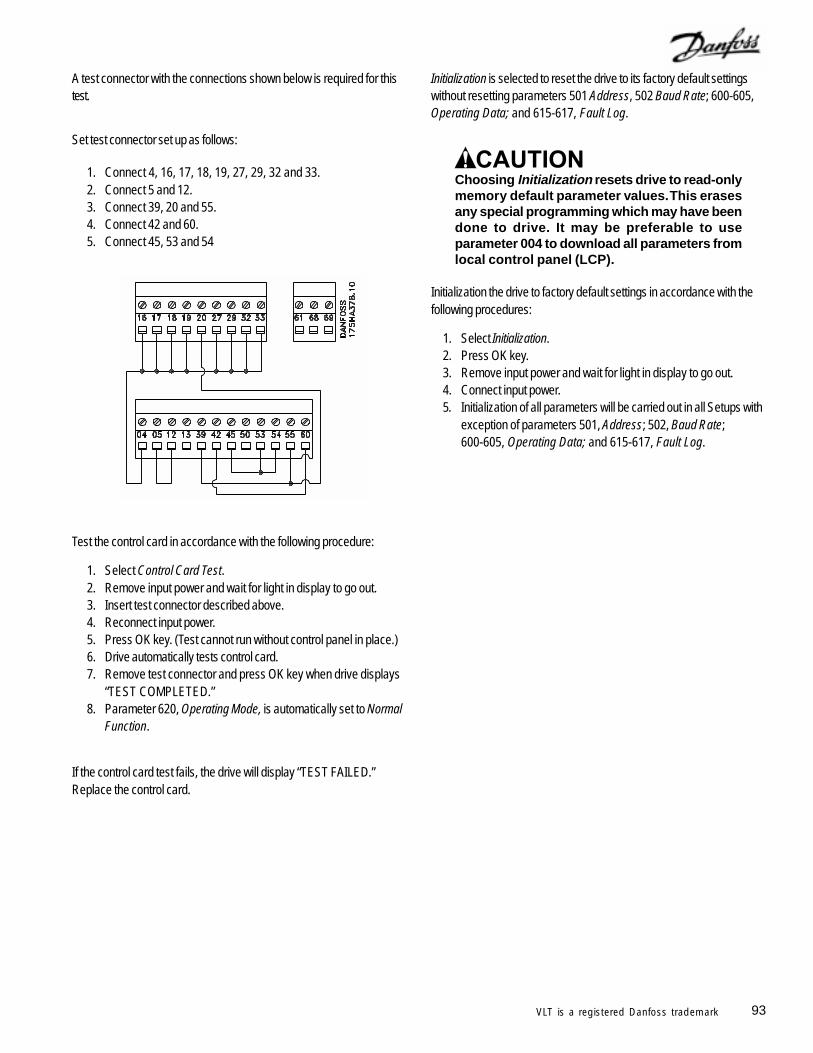
93VLT is a registered Danfoss trademark
A test connector with the connections shown below is required for thistest.
Set test connector set up as follows:
1. Connect 4, 16, 17, 18, 19, 27, 29, 32 and 33.2. Connect 5 and 12.3. Connect 39, 20 and 55.4. Connect 42 and 60.5. Connect 45, 53 and 54
Test the control card in accordance with the following procedure:
1. Select Control Card Test.2. Remove input power and wait for light in display to go out.3. Insert test connector described above.4. Reconnect input power.5. Press OK key. (Test cannot run without control panel in place.)6. Drive automatically tests control card.7. Remove test connector and press OK key when drive displays
“TEST COMPLETED.”8. Parameter 620, Operating Mode, is automatically set to Normal
Function.
If the control card test fails, the drive will display “TEST FAILED.”Replace the control card.
Initialization is selected to reset the drive to its factory default settingswithout resetting parameters 501 Address, 502 Baud Rate; 600-605,Operating Data; and 615-617, Fault Log.
Choosing Initialization resets drive to read-onlymemory default parameter values. This erasesany special programming which may have beendone to drive. It may be preferable to useparameter 004 to download all parameters fromlocal control panel (LCP).
Initialization the drive to factory default settings in accordance with thefollowing procedures:
1. Select Initialization.2. Press OK key.3. Remove input power and wait for light in display to go out.4. Connect input power.5. Initialization of all parameters will be carried out in all Setups with
exception of parameters 501, Address; 502, Baud Rate;600-605, Operating Data; and 615-617, Fault Log.
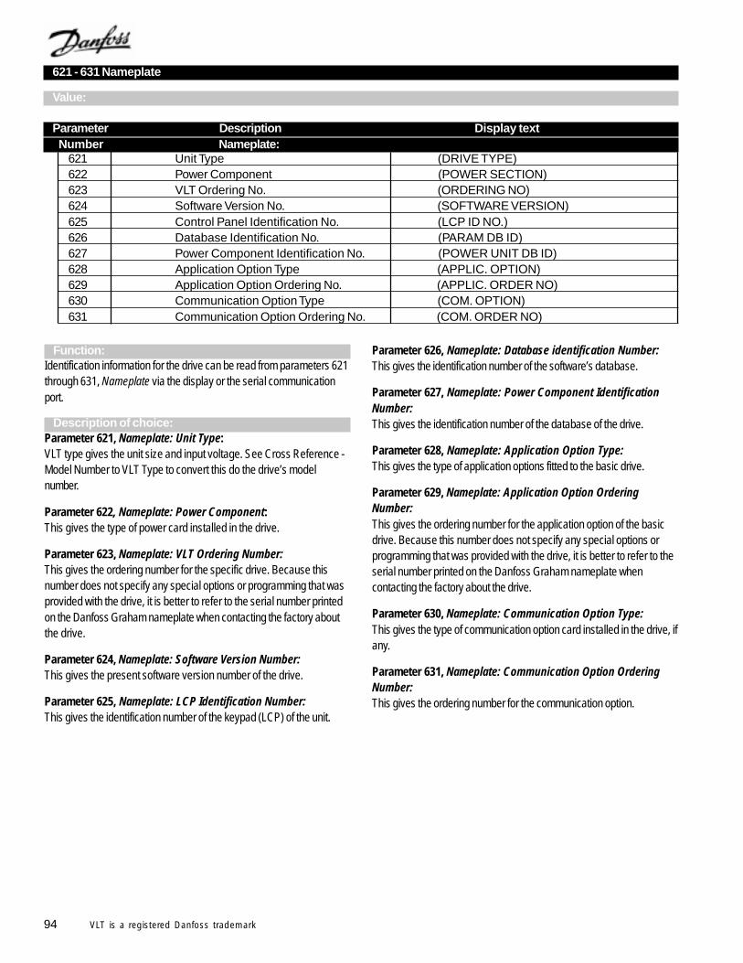
94 VLT is a registered Danfoss trademark
621 - 631 Nameplate
Value:
Parameter Description Display text Number Nameplate:
621 Unit Type (DRIVE TYPE)622 Power Component (POWER SECTION)623 VLT Ordering No. (ORDERING NO)624 Software Version No. (SOFTWARE VERSION)625 Control Panel Identification No. (LCP ID NO.)626 Database Identification No. (PARAM DB ID)627 Power Component Identification No. (POWER UNIT DB ID)628 Application Option Type (APPLIC. OPTION)629 Application Option Ordering No. (APPLIC. ORDER NO)630 Communication Option Type (COM. OPTION)631 Communication Option Ordering No. (COM. ORDER NO)
Function:Identification information for the drive can be read from parameters 621through 631, Nameplate via the display or the serial communicationport.
Description of choice:Parameter 621, Nameplate: Unit Type:VLT type gives the unit size and input voltage. See Cross Reference -Model Number to VLT Type to convert this do the drive’s modelnumber.
Parameter 622, Nameplate: Power Component:This gives the type of power card installed in the drive.
Parameter 623, Nameplate: VLT Ordering Number:This gives the ordering number for the specific drive. Because thisnumber does not specify any special options or programming that wasprovided with the drive, it is better to refer to the serial number printedon the Danfoss Graham nameplate when contacting the factory aboutthe drive.
Parameter 624, Nameplate: Software Version Number:This gives the present software version number of the drive.
Parameter 625, Nameplate: LCP Identification Number:This gives the identification number of the keypad (LCP) of the unit.
Parameter 626, Nameplate: Database identification Number:This gives the identification number of the software’s database.
Parameter 627, Nameplate: Power Component IdentificationNumber:This gives the identification number of the database of the drive.
Parameter 628, Nameplate: Application Option Type:This gives the type of application options fitted to the basic drive.
Parameter 629, Nameplate: Application Option OrderingNumber:This gives the ordering number for the application option of the basicdrive. Because this number does not specify any special options orprogramming that was provided with the drive, it is better to refer to theserial number printed on the Danfoss Graham nameplate whencontacting the factory about the drive.
Parameter 630, Nameplate: Communication Option Type:This gives the type of communication option card installed in the drive, ifany.
Parameter 631, Nameplate: Communication Option OrderingNumber:This gives the ordering number for the communication option.
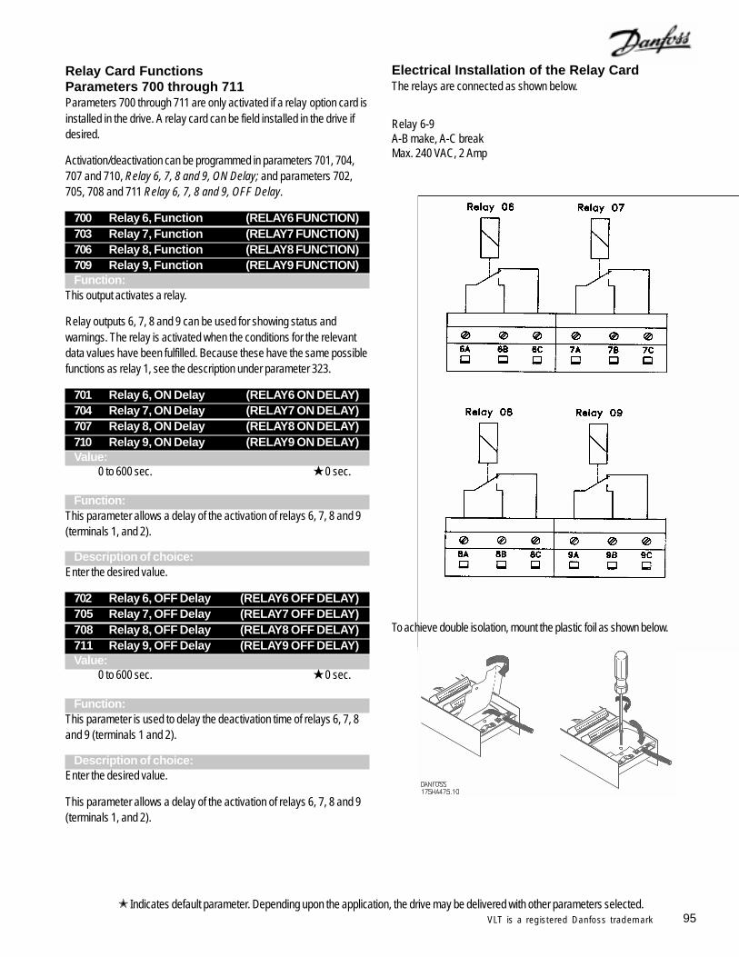
95VLT is a registered Danfoss trademark
Relay Card FunctionsParameters 700 through 711Parameters 700 through 711 are only activated if a relay option card isinstalled in the drive. A relay card can be field installed in the drive ifdesired.
Activation/deactivation can be programmed in parameters 701, 704,707 and 710, Relay 6, 7, 8 and 9, ON Delay; and parameters 702,705, 708 and 711 Relay 6, 7, 8 and 9, OFF Delay.
700 Relay 6, Function (RELAY6 FUNCTION)703 Relay 7, Function (RELAY7 FUNCTION)706 Relay 8, Function (RELAY8 FUNCTION)709 Relay 9, Function (RELAY9 FUNCTION)Function:
This output activates a relay.
Relay outputs 6, 7, 8 and 9 can be used for showing status andwarnings. The relay is activated when the conditions for the relevantdata values have been fulfilled. Because these have the same possiblefunctions as relay 1, see the description under parameter 323.
701 Relay 6, ON Delay (RELAY6 ON DELAY)704 Relay 7, ON Delay (RELAY7 ON DELAY)707 Relay 8, ON Delay (RELAY8 ON DELAY)710 Relay 9, ON Delay (RELAY9 ON DELAY)Value:
0 to 600 sec. 0 sec.
Function:This parameter allows a delay of the activation of relays 6, 7, 8 and 9(terminals 1, and 2).
Description of choice:Enter the desired value.
702 Relay 6, OFF Delay (RELAY6 OFF DELAY)705 Relay 7, OFF Delay (RELAY7 OFF DELAY)708 Relay 8, OFF Delay (RELAY8 OFF DELAY)711 Relay 9, OFF Delay (RELAY9 OFF DELAY)Value:
0 to 600 sec. 0 sec.
Function:This parameter is used to delay the deactivation time of relays 6, 7, 8and 9 (terminals 1 and 2).
Description of choice:Enter the desired value.
This parameter allows a delay of the activation of relays 6, 7, 8 and 9(terminals 1, and 2).
Indicates default parameter. Depending upon the application, the drive may be delivered with other parameters selected.
Electrical Installation of the Relay CardThe relays are connected as shown below.
To achieve double isolation, mount the plastic foil as shown below.
Relay 6-9A-B make, A-C breakMax. 240 VAC, 2 Amp
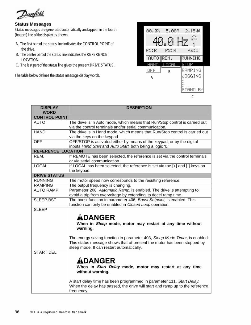
96 VLT is a registered Danfoss trademark
DISPLAY WORD
DESRIPTION
CONTROL POINT AUTO The drive is in Auto mode, which means that Run/Stop control is carried out
via the control terminals and/or serial communication. HAND The drive is in Hand mode, which means that Run/Stop control is carried out
via the keys on the keypad OFF OFF/STOP is activated either by means of the keypad, or by the digital
inputs Hand Start and Auto Start, both being a logic ‘0.’ REFERENCE LOCATION REM. If REMOTE has been selected, the reference is set via the control terminals
or via serial communication. LOCAL If LOCAL has been selected, the reference is set via the [+] and [-] keys on
the keypad. DRIVE STATUS RUNNING The motor speed now corresponds to the resulting reference. RAMPING The output frequency is changing. AUTO RAMP Parameter 208, Automatic Ramp, is enabled. The drive is attempting to
avoid a trip from overvoltage by extending its decel ramp time. SLEEP.BST The boost function in parameter 406, Boost Setpoint, is enabled. This
function can only be enabled in Closed Loop operation. SLEEP
When in Sleep mode, motor may restart at any time without warning.
The energy saving function in parameter 403, Sleep Mode Timer, is enabled. This status message shows that at present the motor has been stopped by sleep mode. It can restart automatically.
START DEL When in Start Delay mode, motor may restart at any time without warning.
A start delay time has been programmed in parameter 111, Start Delay. When the delay has passed, the drive will start and ramp up to the reference frequency.
Status MessagesStatus messages are generated automatically and appear in the fourth(bottom) line of the display as shown.
A. The first part of the status line indicates the CONTROL POINT ofthe drive.
B. The center part of the status line indicates the REFERENCELOCATION.
C. The last part of the status line gives the present DRIVE STATUS.
The table below defines the status massage display words.
! "
##
AB
C
,,*,
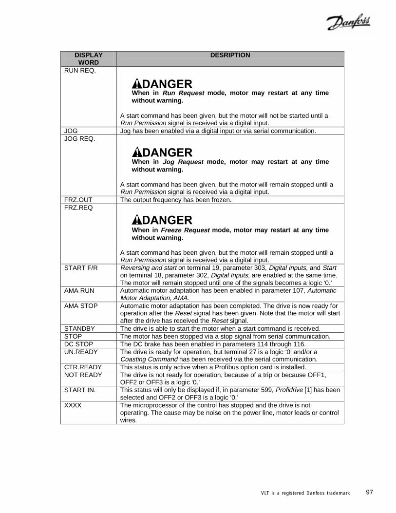
97VLT is a registered Danfoss trademark
DISPLAY WORD
DESRIPTION
RUN REQ.
When in Run Request mode, motor may restart at any time without warning.
A start command has been given, but the motor will not be started until a Run Permission signal is received via a digital input.
JOG Jog has been enabled via a digital input or via serial communication. JOG REQ.
When in Jog Request mode, motor may restart at any time without warning.
A start command has been given, but the motor will remain stopped until a Run Permission signal is received via a digital input.
FRZ.OUT The output frequency has been frozen. FRZ.REQ
When in Freeze Request mode, motor may restart at any time without warning.
A start command has been given, but the motor will remain stopped until a Run Permission signal is received via a digital input.
START F/R Reversing and start on terminal 19, parameter 303, Digital Inputs, and Start on terminal 18, parameter 302, Digital Inputs, are enabled at the same time. The motor will remain stopped until one of the signals becomes a logic ‘0.’
AMA RUN Automatic motor adaptation has been enabled in parameter 107, Automatic Motor Adaptation, AMA.
AMA STOP Automatic motor adaptation has been completed. The drive is now ready for operation after the Reset signal has been given. Note that the motor will start after the drive has received the Reset signal.
STANDBY The drive is able to start the motor when a start command is received. STOP The motor has been stopped via a stop signal from serial communication. DC STOP The DC brake has been enabled in parameters 114 through 116. UN.READY The drive is ready for operation, but terminal 27 is a logic ‘0’ and/or a
Coasting Command has been received via the serial communication. CTR.READY This status is only active when a Profibus option card is installed. NOT READY The drive is not ready for operation, because of a trip or because OFF1,
OFF2 or OFF3 is a logic ‘0.’ START IN. This status will only be displayed if, in parameter 599, Profidrive [1] has been
selected and OFF2 or OFF3 is a logic ‘0.’ XXXX The microprocessor of the control has stopped and the drive is not
operating. The cause may be noise on the power line, motor leads or control wires.
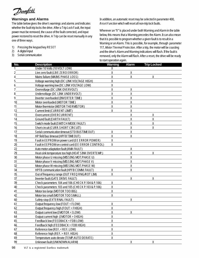
98 VLT is a registered Danfoss trademark
Warnings and AlarmsThe table below gives the drive’s warnings and alarms and indicateswhether the fault trip locks the drive. After a Trip Lock Fault, the inputpower must be removed, the cause of the fault corrected, and inputpower restored to reset the drive. A Trip can be reset manually in anyone of three ways.
1) Pressing the keypad key RESET2) A digital input3) Serial communication
In addition, an automatic reset may be selected in parameter 400,Reset Function which will reset all non-trip lock faults.
Wherever an “X” is placed under both Warning and Alarm in the tablebelow, this means that a Warning precedes the Alarm. It can also meanthat it is possible to program whether a given fault is to result in aWarning or an Alarm. This is possible, for example, through parameter117, Motor Thermal Protection. After a trip, the motor will be coastingand the drive’s Alarm and Warning indications will flash. If the fault isremoved, only the Alarm will flash. After a reset, the drive will be readyto start operation again.
No. Description Warning Alarm Trip Locked1 Under 10 Volts (10 VOLT LOW) X2 Live zero fault (LIVE ZERO ERROR) X X4 Mains failure (MAINS PHASE LOSS) X X X5 Voltage warning high (DC LINK VOLTAGE HIGH) X6 Voltage warning low (DC LINK VOLTAGE LOW) X7 Overvoltage (DC LINK OVERVOLT) X X8 Undervoltage (DC LINK UNDERVOLT) X X9 Inverter overloaded (INVERTER TIME) X X10 Motor overloaded (MOTOR TIME) X X11 Motor thermistor (MOTOR THERMISTOR) X X12 Current limit (CURRENT LIMIT) X X13 Overcurrent (OVERCURRENT) X X14 Ground fault (EARTH FAULT) X X15 Switch mode fault (SWITCH MODE FAULT) X X16 Short circuit (CURR.SHORT CIRCUIT) X X17 Serial communication timeout (STD BUSTIMEOUT) X X18 HP field bus timeout (HPFB TIMEOUT) X X19 Fault in EEPROM on power card (EE ERROR POWER) X20 Fault in EEPROM on control card (EE ERROR CONTROL) X22 Auto motor adaptation fault (AMA FAULT) X29 Heat-sink temperature too high (HEAT SINK OVERTEMP.) X X30 Motor phase U missing (MISSING MOT.PHASE U) X31 Motor phase V missing (MISSING MOT.PHASE V) X32 Motor phase W missing (MISSING MOT.PHASE W) X34 HPFB communication fault (HPFB COMM. FAULT) X X35 Out of frequency range (OUT FREQ RNG/ROT LIM) X37 Inverter fault (GATE DRIVE FAULT) X X39 Check parameters 104 and 106 (CHECK P.104 & P.106) X40 Check parameters 103 and 105 (CHECK P.103 & P.106) X41 Motor too large (MOTOR TOO BIG) X42 Motor too small (MOTOR TOO SMALL) X60 Safety stop (EXTERNAL FAULT) X61 Output frequency low (FOUT < FLOW) X62 Output frequency high (FOUT > FHIGH) X63 Output current low (I MOTOR < I LOW) X X64 Output current high (I MOTOR > I HIGH) X65 Feedback low (FEEDBACK < FDB LOW) X66 Feedback high (FEEDBACK > FDB HIGH) X67 Reference low (REF. < REF. LOW) X68 Reference high (REF. > REF. HIGH) X69 Temperature auto derate (TEMP.AUTO DERATE) X99 Unknown fault (UNKNOWN ALARM) X X
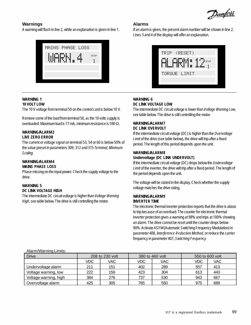
99VLT is a registered Danfoss trademark
WarningsA warning will flash in line 2, while an explanation is given in line 1.
WARNING 110 VOLT LOWThe 10 V voltage from terminal 50 on the control card is below 10 V.
Remove some of the load from terminal 50, as the 10 volts supply isoverloaded. Maximum load is 17 mA, minimum resistance is 590 Ω.
WARNING/ALARM 2LIVE ZERO ERRORThe current or voltage signal on terminal 53, 54 or 60 is below 50% ofthe value preset in parameters 309, 312 and 315 Terminal, MinimumScaling.
WARNING/ALARM 4MAINS PHASE LOSSPhase missing on the input power. Check the supply voltage to thedrive.
WARNING 5DC LINK VOLTAGE HIGHThe intermediate DC circuit voltage is higher than Voltage WarningHigh, see table below. The drive is still controlling the motor.
Alarm/Warning Limits:Drive 208 to 230 volt 380 to 460 volt 550 to 600 volt
VDC VAC VDC VAC VDC VACUndervoltage alarm 211 151 402 289 557 413Voltage warning, low 222 159 423 304 613 443Voltage warning, high 384 276 737 530 943 667Overvoltage alarm 425 305 765 550 975 689
AlarmsIf an alarm is given, the present alarm number will be shown in line 2.Lines 3 and 4 of the display will offer an explanation.
WARNING 6DC LINK VOLTAGE LOWThe intermediate DC circuit voltage is lower than Voltage Warning Low,see table below. The drive is still controlling the motor.
WARNING/ALARM 7DC LINK OVERVOLTIf the intermediate circuit voltage (DC) is higher than the OvervoltageLimit of the drive (see table below), the drive will trip after a fixedperiod. The length of this period depends upon the unit.
WARNING/ALARM 8Undervoltage (DC LINK UNDERVOLT)If the intermediate circuit voltage (DC) drops below the UndervoltageLimit of the inverter, the drive will trip after a fixed period. The length ofthe period depends upon the unit.
The voltage will be stated in the display. Check whether the supplyvoltage matches the drive rating.
WARNING/ALARM 9INVERTER TIMEThe electronic thermal inverter protection reports that the drive is aboutto trip because of an overload. The counter for electronic thermalinverter protection gives a warning at 98% and trips at 100% showingan alarm. The drive cannot be reset until the counter drops below90%. Activate ASFM (Automatic Switching Frequency Modulation) inparameter 408, Interference Reduction Method, or reduce the carrierfrequency in parameter 407, Switching Frequency.
#
#,
/0
#
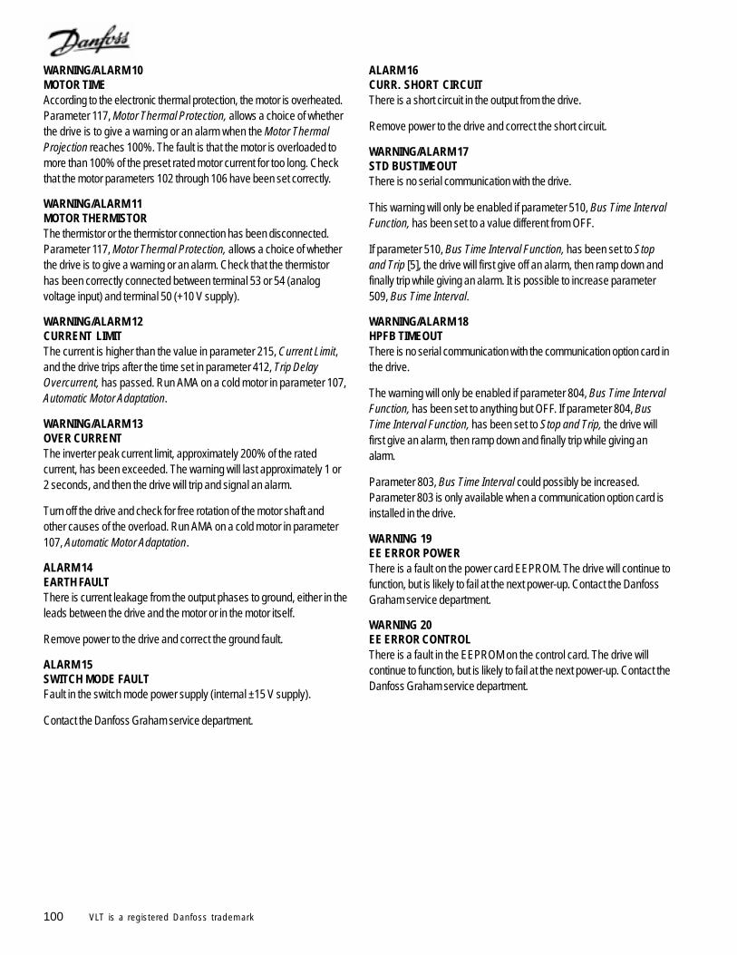
100 VLT is a registered Danfoss trademark
WARNING/ALARM 10MOTOR TIMEAccording to the electronic thermal protection, the motor is overheated.Parameter 117, Motor Thermal Protection, allows a choice of whetherthe drive is to give a warning or an alarm when the Motor ThermalProjection reaches 100%. The fault is that the motor is overloaded tomore than 100% of the preset rated motor current for too long. Checkthat the motor parameters 102 through 106 have been set correctly.
WARNING/ALARM 11MOTOR THERMISTORThe thermistor or the thermistor connection has been disconnected.Parameter 117, Motor Thermal Protection, allows a choice of whetherthe drive is to give a warning or an alarm. Check that the thermistorhas been correctly connected between terminal 53 or 54 (analogvoltage input) and terminal 50 (+10 V supply).
WARNING/ALARM 12CURRENT LIMITThe current is higher than the value in parameter 215, Current Limit,and the drive trips after the time set in parameter 412, Trip DelayOvercurrent, has passed. Run AMA on a cold motor in parameter 107,Automatic Motor Adaptation.
WARNING/ALARM 13OVER CURRENTThe inverter peak current limit, approximately 200% of the ratedcurrent, has been exceeded. The warning will last approximately 1 or2 seconds, and then the drive will trip and signal an alarm.
Turn off the drive and check for free rotation of the motor shaft andother causes of the overload. Run AMA on a cold motor in parameter107, Automatic Motor Adaptation.
ALARM 14EARTH FAULTThere is current leakage from the output phases to ground, either in theleads between the drive and the motor or in the motor itself.
Remove power to the drive and correct the ground fault.
ALARM 15SWITCH MODE FAULTFault in the switch mode power supply (internal ±15 V supply).
Contact the Danfoss Graham service department.
ALARM 16CURR. SHORT CIRCUITThere is a short circuit in the output from the drive.
Remove power to the drive and correct the short circuit.
WARNING/ALARM 17STD BUSTIMEOUTThere is no serial communication with the drive.
This warning will only be enabled if parameter 510, Bus Time IntervalFunction, has been set to a value different from OFF.
If parameter 510, Bus Time Interval Function, has been set to Stopand Trip [5], the drive will first give off an alarm, then ramp down andfinally trip while giving an alarm. It is possible to increase parameter509, Bus Time Interval.
WARNING/ALARM 18HPFB TIMEOUTThere is no serial communication with the communication option card inthe drive.
The warning will only be enabled if parameter 804, Bus Time IntervalFunction, has been set to anything but OFF. If parameter 804, BusTime Interval Function, has been set to Stop and Trip, the drive willfirst give an alarm, then ramp down and finally trip while giving analarm.
Parameter 803, Bus Time Interval could possibly be increased.Parameter 803 is only available when a communication option card isinstalled in the drive.
WARNING 19EE ERROR POWERThere is a fault on the power card EEPROM. The drive will continue tofunction, but is likely to fail at the next power-up. Contact the DanfossGraham service department.
WARNING 20EE ERROR CONTROLThere is a fault in the EEPROM on the control card. The drive willcontinue to function, but is likely to fail at the next power-up. Contact theDanfoss Graham service department.
101VLT is a registered Danfoss trademark
ALARM 22AMA FAULTA fault has been found during automatic motor adaptation (AMA). Thetext shown in the display indicates a fault message.
AMA can only be carried out if there are no alarms during the AMAprocess.
CHECK 103, 105Parameter 103 or 105 has a wrong setting. Correct the settingand repeat AMA.
LOW P 105The motor is too small for AMA to be carried out. If AMA is to beenabled, the rated motor current, parameter 105, must be higherthan 35% of the rated output current of the drive.
ASYMMETRICAL IMPEDANCEAMA has detected an asymmetrical impedance in the motorconnected to the system. The motor could be defective.
MOTOR TOO BIGThe motor connected to the system is too big for AMA to becarried out. The setting in parameter 102 does not match themotor used.
MOTOR TOO SMALLThe motor connected to the system is too small for AMA to becarried out. The setting in parameter 102 does not match themotor used.
TIME OUTAMA fails because of noisy measuring signals. Retry until AMA issuccessfully completed. Please note that repeated AMA runs mayheat the motor to a level where the stator resistance is increased.
INTERRUPTED BY USERAMA has been interrupted by the user.
INTERNAL FAULTAn internal fault has occurred in the drive. Contact DanfossGraham service department.
LIMIT VALUE FAULTThe parameter values found for the motor are outside theacceptable range within which the drive is able to work.
MOTOR ROTATESThe motor shaft is rotating. Make sure that the load is not able tomake the motor shaft rotate while the AMA is being performed.Then start AMA all over.
ALARM 29HEAT SINK OVER TEMP.The heatsink temperature became too high. For NEMA 1 drives, thelimit is 90°C. For NEMA 12 drives, the limit is 80°C. The tolerance is±5°C. The fault cannot be reset until the temperature of the heatsinkhas fallen below 60°C.
The fault could be due to the following:- Ambient temperature too high- Air obstructed- Cooling fan(s) not operating- Motor leads too long- Too high a switching frequency
ALARM 30MISSING MOT.PHASE UMotor phase U, as indicated by the letters on the output terminal block,is missing or has a high impedance.
Remove power to the drive and check motor phase U.
ALARM 31MISSING MOT.PHASE VMotor phase V, as indicated by the letters on the output terminal block ismissing or has a high impedance.
Remove power to the drive and check motor phase V.
ALARM 32MISSING MOT.PHASE WMotor phase W, as indicated by the letters on the output terminal blockis missing or has a high impedance.
Remove power to the drive and check motor phase W.
WARNING/ALARM 34HPFB COMM. FAULTThe serial communication on the communication option card is notworking.
WARNING 35OUT FREQ RNG/ROT LIMThis warning will occur if the output frequency has reached its OutputFrequency Low Limit , parameter 201, or Output Frequency HighLimit, parameter 202. If the drive is in Closed Loop, parameter 100, thewarning will show in the display.
102 VLT is a registered Danfoss trademark
ALARM 37GATE DRIVE FAULTAn output IGBT or the power card is defective. Contact the DanfossGraham service department.
Auto Optimization Warnings 39 through 42Automatic motor adaptation has stopped, because some parametershave probably been improperly set, or the motor used in too large orsmall for AMA to be carried out.
A choice must be made by pressing CHANGE DATA and choosing‘Continue’ + OK or ‘Stop’ + OK.
If parameters need to be changed, select ‘Stop’, change the parametersand run AMA again.
WARNING 39CHECK PAR. 104, 106Parameters 104, Motor Frequency, or 106, Rated Motor Speed, haveprobably not been set correctly. Correct the setting and run AMAagain.
WARNING 40CHECK PAR. 103, 105Parameter 103 Motor Voltage, or 105 Motor Current, has not been setcorrectly. Correct the setting and run AMA again.
WARNING 41MOTOR TOO BIGThe motor used is probably too large for AMA to be carried out. Thesetting in parameter 102 Motor Power, may not match the motor. Checkthe motor and select ‘Continue’ or [STOP].
WARNING 42MOTOR TOO SMALLThe motor used is probably too small for AMA to be carried out. Thesetting in parameter 102 Motor Power, may not match the motor. Checkthe motor and select ‘Continue’ or [STOP].
ALARM 60EXTERNAL FAULTTerminal 27, parameter 304, Digital Inputs, has been programmed fora Safety Interlock and is a logic ‘0’.
WARNING 61FOUT < FLOWThe output frequency is lower than parameter 223, Warning: LowFrequency.
WARNING 62FOUT > FHIGHThe output frequency is higher than parameter 224, Warning: HighFrequency.
WARNING/ALARM 63I MOTOR < I LOWThe output current is lower than parameter 221, Warning: LowCurrent. Select the required function in parameter 409, Function inCase of No Load.
WARNING 64I MOTOR > I HIGHThe output current is higher than parameter 222, Warning: HighCurrent.
WARNING 65FEEDBACK < FDB LOWThe resulting feedback value is lower than parameter 227, Warning:Low Feedback.
WARNING 66FEEDBACK > FDB HIGHThe resulting feedback value is higher than parameter 228, Warning:High Feedback.
WARNING 67REF. < REF LOWThe remote controlled reference is lower than parameter 225,Warning: Low Reference.
WARNING 68REF. > REF HIGHThe remote controlled reference is higher than parameter 226,Warning: High Reference.
WARNING 69TEMP.AUTO DERATEThe heat sink temperature has exceeded the maximum value and theauto derating function in parameter 411, Function at Over Temp, isactive.
WARNING 99UNKNOWN ALARMAn unknown fault has occurred which the software is not able tohandle. Contact Danfoss Graham service department.
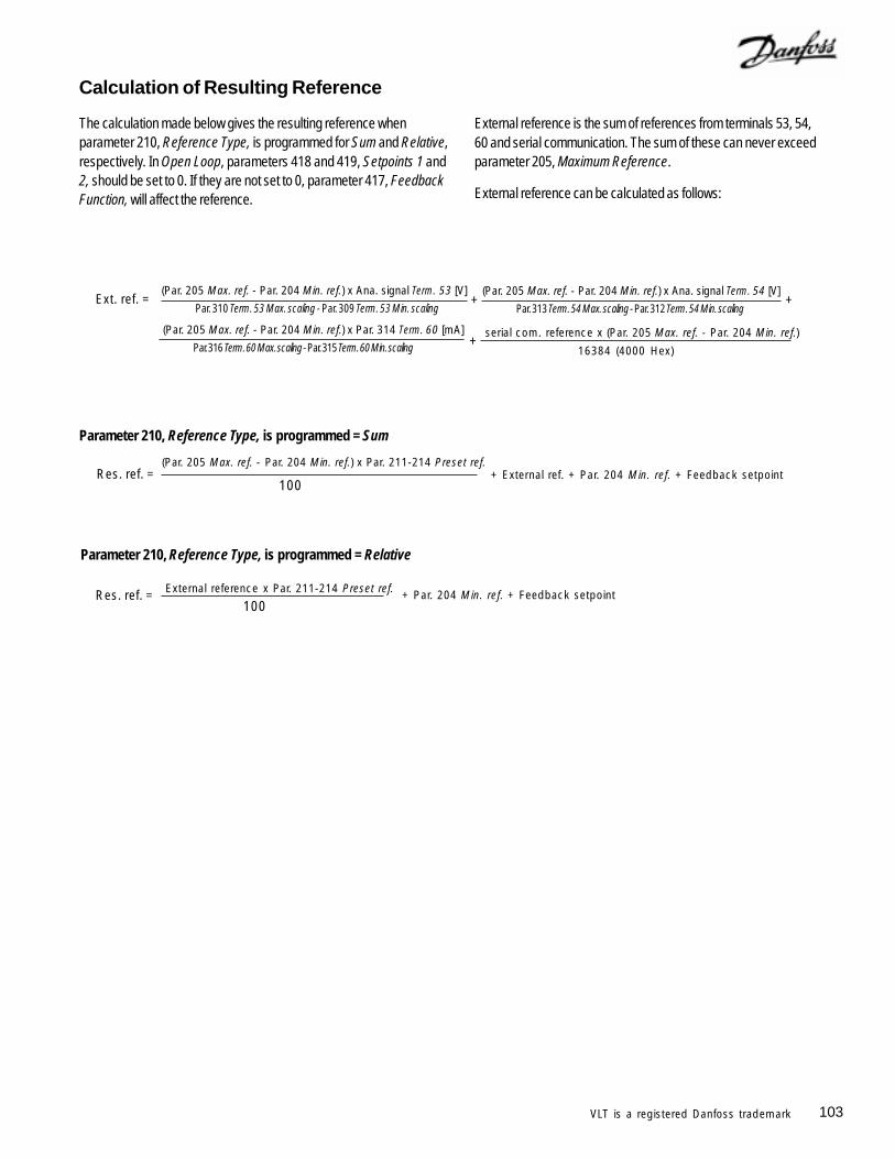
103VLT is a registered Danfoss trademark
Calculation of Resulting Reference
The calculation made below gives the resulting reference whenparameter 210, Reference Type, is programmed for Sum and Relative,respectively. In Open Loop, parameters 418 and 419, Setpoints 1 and2, should be set to 0. If they are not set to 0, parameter 417, FeedbackFunction, will affect the reference.
External reference is the sum of references from terminals 53, 54,60 and serial communication. The sum of these can never exceedparameter 205, Maximum Reference.
External reference can be calculated as follows:
+ External ref. + Par. 204 Min. ref. + Feedback setpoint
External reference x Par. 211-214 Preset ref.
Parameter 210, Reference Type, is programmed = Relative
+ Par. 204 Min. ref. + Feedback setpointRes. ref. =100
Parameter 210, Reference Type, is programmed = Sum
Res. ref. =(Par. 205 Max. ref. - Par. 204 Min. ref.) x Par. 211-214 Preset ref.
100
Ext. ref. =Par. 310 Term. 53 Max. scaling - Par. 309 Term. 53 Min. scaling
(Par. 205 Max. ref. - Par. 204 Min. ref.) x Ana. signal Term. 53 [V]+
Par. 313 Term. 54 Max. scaling - Par. 312 Term. 54 Min. scaling
(Par. 205 Max. ref. - Par. 204 Min. ref.) x Ana. signal Term. 54 [V]+
Par. 316 Term. 60 Max. scaling - Par. 315 Term. 60 Min. scaling
(Par. 205 Max. ref. - Par. 204 Min. ref.) x Par. 314 Term. 60 [mA]+ serial com. reference x (Par. 205 Max. ref. - Par. 204 Min. ref.)
16384 (4000 Hex)
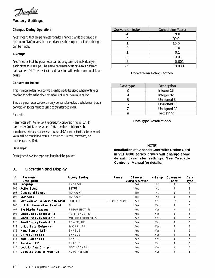
104 VLT is a registered Danfoss trademark
0.. Operation and Display
# # # # # ParameterParameterParameterParameterParameter Factory SettingFactory SettingFactory SettingFactory SettingFactory Setting RangeRangeRangeRangeRange ChangesChangesChangesChangesChanges 4-Setup4-Setup4-Setup4-Setup4-Setup ConversionConversionConversionConversionConversion DataDataDataDataDataDescriptionDescriptionDescriptionDescriptionDescription During OperationDuring OperationDuring OperationDuring OperationDuring Operation IndexIndexIndexIndexIndex TTTTTypeypeypeypeype
001 LanguageLanguageLanguageLanguageLanguage ENGLISH Yes No 0 5
002 Active SetupActive SetupActive SetupActive SetupActive Setup SETUP 1 Yes No 0 5
003 Copying of SetupsCopying of SetupsCopying of SetupsCopying of SetupsCopying of Setups NO COPY No No 0 5
004 LCP CopyLCP CopyLCP CopyLCP CopyLCP Copy NO COPY No No 0 5
005 Max Value of User-defined ReadoutMax Value of User-defined ReadoutMax Value of User-defined ReadoutMax Value of User-defined ReadoutMax Value of User-defined Readout 100.000 0 - 999.999,999 Yes Yes -2 4
006 Unit for User-defined ReadoutUnit for User-defined ReadoutUnit for User-defined ReadoutUnit for User-defined ReadoutUnit for User-defined Readout % Yes Yes 0 5
007 Big Display ReadoutBig Display ReadoutBig Display ReadoutBig Display ReadoutBig Display Readout FREQUENCY, % Yes Yes 0 5
008 Small Display Readout 1.1Small Display Readout 1.1Small Display Readout 1.1Small Display Readout 1.1Small Display Readout 1.1 REFERENCE, % Yes Yes 0 5
009 Small Display Readout 1.2Small Display Readout 1.2Small Display Readout 1.2Small Display Readout 1.2Small Display Readout 1.2 MOTOR CURRENT, A Yes Yes 0 5
010 Small Display Readout 1.3Small Display Readout 1.3Small Display Readout 1.3Small Display Readout 1.3Small Display Readout 1.3 POWER, HP Yes Yes 0 5
011 Unit of Local ReferenceUnit of Local ReferenceUnit of Local ReferenceUnit of Local ReferenceUnit of Local Reference % OF F MAX Yes Yes 0 5
012 Hand Start on LCPHand Start on LCPHand Start on LCPHand Start on LCPHand Start on LCP ENABLE Yes Yes 0 5
013 OFF/OFF/OFF/OFF/OFF/STOPSTOPSTOPSTOPSTOP on LCP on LCP on LCP on LCP on LCP ENABLE Yes Yes 0 5
014 Auto Start on LCPAuto Start on LCPAuto Start on LCPAuto Start on LCPAuto Start on LCP ENABLE Yes Yes 0 5
015 Reset on LCPReset on LCPReset on LCPReset on LCPReset on LCP ENABLE Yes Yes 0 5
016 Lock for Data ChangeLock for Data ChangeLock for Data ChangeLock for Data ChangeLock for Data Change NOT LOCKED Yes Yes 0 5
017 Operating State at Power-upOperating State at Power-upOperating State at Power-upOperating State at Power-upOperating State at Power-up AUTO RESTART Yes Yes 0 5
Factory Settings
Changes During Operation:
“Yes” means that the parameter can be changed while the drive is inoperation. “No” means that the drive must be stopped before a changecan be made.
4-Setup:
“Yes” means that the parameter can be programmed individually ineach of the four setups. The same parameter can have four differentdata values. “No” means that the data value will be the same in all foursetups.
Conversion Index:
This number refers to a conversion figure to be used when writing orreading to or from the drive by means of serial communication.
Since a parameter value can only be transferred as a whole number, aconversion factor must be used to transfer decimals.
Example:
Parameter 201: Minimum Frequency, conversion factor 0.1. Ifparameter 201 is to be set to 10 Hz, a value of 100 must betransferred, since a conversion factor of 0.1 means that the transferredvalue will be multiplied by 0.1. A value of 100 will, therefore, beunderstood as 10.0.
Data type:
Data type shows the type and length of the packet.
Conversion Index Conversion Factor 74 3.6 2 100.0 1 10.0 0 1.0 -1 0.1 -2 0.01 -3 0.001 -4 0.0001
Data type Description3 Integer 16
4 Integer 325 Unsigned 86 Unsigned 167 Unsigned 32
9 Text string
Conversion Index Factors
Data Type Descriptions
NOTEInstallation of Cascade Controller Option Cardin VLT 6000 series drives will change somedefault parameter settings. See CascadeController Manual for details.
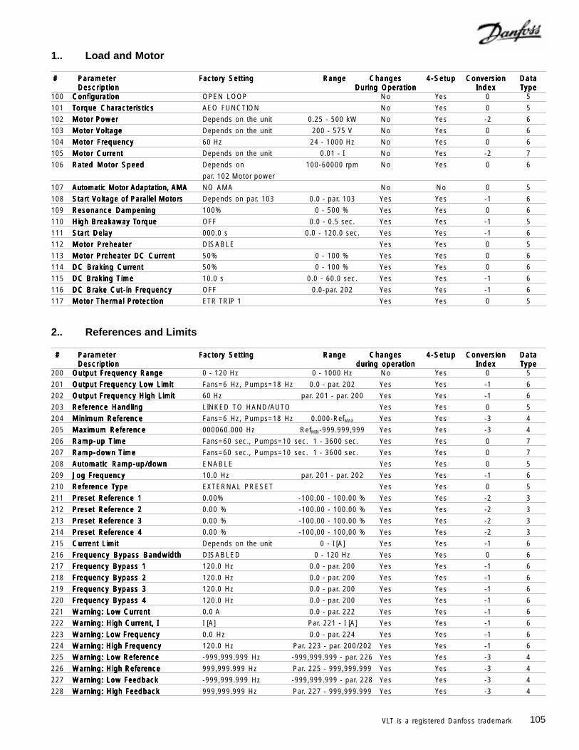
105VLT is a registered Danfoss trademark
2.. References and Limits
# # # # # ParameterParameterParameterParameterParameter Factory SettingFactory SettingFactory SettingFactory SettingFactory Setting RangeRangeRangeRangeRange ChangesChangesChangesChangesChanges 4-Setup4-Setup4-Setup4-Setup4-Setup ConversionConversionConversionConversionConversion DataDataDataDataDataDescriptionDescriptionDescriptionDescriptionDescription during operationduring operationduring operationduring operationduring operation IndexIndexIndexIndexIndex TTTTTypeypeypeypeype
200 Output Frequency RangeOutput Frequency RangeOutput Frequency RangeOutput Frequency RangeOutput Frequency Range 0 - 120 Hz 0 - 1000 Hz No Yes 0 5
201 Output Frequency Low LimitOutput Frequency Low LimitOutput Frequency Low LimitOutput Frequency Low LimitOutput Frequency Low Limit Fans=6 Hz, Pumps=18 Hz 0.0 - par. 202 Yes Yes -1 6
202 Output Frequency High LimitOutput Frequency High LimitOutput Frequency High LimitOutput Frequency High LimitOutput Frequency High Limit 60 Hz par. 201 - par. 200 Yes Yes -1 6
203 Reference HandlingReference HandlingReference HandlingReference HandlingReference Handling LINKED TO HAND/AUTO Yes Yes 0 5
204 Minimum ReferenceMinimum ReferenceMinimum ReferenceMinimum ReferenceMinimum Reference Fans=6 Hz, Pumps=18 Hz 0.000-RefMAX Yes Yes -3 4
205 Maximum ReferenceMaximum ReferenceMaximum ReferenceMaximum ReferenceMaximum Reference 000060.000 Hz RefMIN-999.999,999 Yes Yes -3 4
206 Ramp-up TRamp-up TRamp-up TRamp-up TRamp-up Timeimeimeimeime Fans=60 sec., Pumps=10 sec. 1 - 3600 sec. Yes Yes 0 7
207 Ramp-down TRamp-down TRamp-down TRamp-down TRamp-down Timeimeimeimeime Fans=60 sec., Pumps=10 sec. 1 - 3600 sec. Yes Yes 0 7
208 Automatic Ramp-up/downAutomatic Ramp-up/downAutomatic Ramp-up/downAutomatic Ramp-up/downAutomatic Ramp-up/down ENABLE Yes Yes 0 5
209 Jog FrequencyJog FrequencyJog FrequencyJog FrequencyJog Frequency 10.0 Hz par. 201 - par. 202 Yes Yes -1 6
210 ReferReferReferReferReference Tence Tence Tence Tence Typeypeypeypeype EXTERNAL PRESET Yes Yes 0 5
211 Preset Reference 1Preset Reference 1Preset Reference 1Preset Reference 1Preset Reference 1 0.00% -100.00 - 100.00 % Yes Yes -2 3
212 Preset Reference 2Preset Reference 2Preset Reference 2Preset Reference 2Preset Reference 2 0.00 % -100.00 - 100.00 % Yes Yes -2 3
213 Preset Reference 3Preset Reference 3Preset Reference 3Preset Reference 3Preset Reference 3 0.00 % -100.00 - 100.00 % Yes Yes -2 3
214 Preset Reference 4Preset Reference 4Preset Reference 4Preset Reference 4Preset Reference 4 0.00 % -100,00 - 100,00 % Yes Yes -2 3
215 Current LimitCurrent LimitCurrent LimitCurrent LimitCurrent Limit Depends on the unit 0 - I [A] Yes Yes -1 6
216 Frequency Bypass BandwidthFrequency Bypass BandwidthFrequency Bypass BandwidthFrequency Bypass BandwidthFrequency Bypass Bandwidth DISABLED 0 - 120 Hz Yes Yes 0 6
217 Frequency Bypass 1Frequency Bypass 1Frequency Bypass 1Frequency Bypass 1Frequency Bypass 1 120.0 Hz 0.0 - par. 200 Yes Yes -1 6
218 Frequency Bypass 2Frequency Bypass 2Frequency Bypass 2Frequency Bypass 2Frequency Bypass 2 120.0 Hz 0.0 - par. 200 Yes Yes -1 6
219 Frequency Bypass 3Frequency Bypass 3Frequency Bypass 3Frequency Bypass 3Frequency Bypass 3 120.0 Hz 0.0 - par. 200 Yes Yes -1 6
220 Frequency Bypass 4Frequency Bypass 4Frequency Bypass 4Frequency Bypass 4Frequency Bypass 4 120.0 Hz 0.0 - par. 200 Yes Yes -1 6
221 Warning: Low CurrentWarning: Low CurrentWarning: Low CurrentWarning: Low CurrentWarning: Low Current 0.0 A 0.0 - par. 222 Yes Yes -1 6
222 Warning: High Current, IWarning: High Current, IWarning: High Current, IWarning: High Current, IWarning: High Current, I I [A] Par. 221 - I [A] Yes Yes -1 6
223 Warning: Low FrequencyWarning: Low FrequencyWarning: Low FrequencyWarning: Low FrequencyWarning: Low Frequency 0.0 Hz 0.0 - par. 224 Yes Yes -1 6
224 Warning: High FrequencyWarning: High FrequencyWarning: High FrequencyWarning: High FrequencyWarning: High Frequency 120.0 Hz Par. 223 - par. 200/202 Yes Yes -1 6
225 Warning: Low ReferenceWarning: Low ReferenceWarning: Low ReferenceWarning: Low ReferenceWarning: Low Reference -999,999.999 Hz -999,999.999 - par. 226 Yes Yes -3 4
226 Warning: High ReferenceWarning: High ReferenceWarning: High ReferenceWarning: High ReferenceWarning: High Reference 999,999.999 Hz Par. 225 - 999,999.999 Yes Yes -3 4
227 Warning: Low FeedbackWarning: Low FeedbackWarning: Low FeedbackWarning: Low FeedbackWarning: Low Feedback -999,999.999 Hz -999,999.999 - par. 228 Yes Yes -3 4
228 Warning: High FeedbackWarning: High FeedbackWarning: High FeedbackWarning: High FeedbackWarning: High Feedback 999,999.999 Hz Par. 227 - 999,999.999 Yes Yes -3 4
1.. Load and Motor
# # # # # ParameterParameterParameterParameterParameter Factory SettingFactory SettingFactory SettingFactory SettingFactory Setting RangeRangeRangeRangeRange ChangesChangesChangesChangesChanges 4-Setup4-Setup4-Setup4-Setup4-Setup ConversionConversionConversionConversionConversion DataDataDataDataDataDescriptionDescriptionDescriptionDescriptionDescription During OperationDuring OperationDuring OperationDuring OperationDuring Operation IndexIndexIndexIndexIndex TTTTTypeypeypeypeype
100 ConfigurationConfigurationConfigurationConfigurationConfiguration OPEN LOOP No Yes 0 5
101 TTTTTorororororque Characteristicsque Characteristicsque Characteristicsque Characteristicsque Characteristics AEO FUNCTION No Yes 0 5
102 Motor PowerMotor PowerMotor PowerMotor PowerMotor Power Depends on the unit 0.25 - 500 kW No Yes -2 6
103 Motor VoltageMotor VoltageMotor VoltageMotor VoltageMotor Voltage Depends on the unit 200 - 575 V No Yes 0 6
104 Motor FrequencyMotor FrequencyMotor FrequencyMotor FrequencyMotor Frequency 60 Hz 24 - 1000 Hz No Yes 0 6
105 Motor CurrentMotor CurrentMotor CurrentMotor CurrentMotor Current Depends on the unit 0.01 - I No Yes -2 7
106 Rated Motor SpeedRated Motor SpeedRated Motor SpeedRated Motor SpeedRated Motor Speed Depends on 100-60000 rpm No Yes 0 6
par. 102 Motor power
107 Automatic Motor Adaptation, AMAAutomatic Motor Adaptation, AMAAutomatic Motor Adaptation, AMAAutomatic Motor Adaptation, AMAAutomatic Motor Adaptation, AMA NO AMA No No 0 5
108 Start Voltage of Parallel MotorsStart Voltage of Parallel MotorsStart Voltage of Parallel MotorsStart Voltage of Parallel MotorsStart Voltage of Parallel Motors Depends on par. 103 0.0 - par. 103 Yes Yes -1 6
109 Resonance DampeningResonance DampeningResonance DampeningResonance DampeningResonance Dampening 100% 0 - 500 % Yes Yes 0 6
110 High BrHigh BrHigh BrHigh BrHigh Breakaway Teakaway Teakaway Teakaway Teakaway Torororororquequequequeque OFF 0.0 - 0.5 sec. Yes Yes -1 5
111 Start DelayStart DelayStart DelayStart DelayStart Delay 000.0 s 0.0 - 120.0 sec. Yes Yes -1 6
112 Motor PreheaterMotor PreheaterMotor PreheaterMotor PreheaterMotor Preheater DISABLE Yes Yes 0 5
113 Motor Preheater DC CurrentMotor Preheater DC CurrentMotor Preheater DC CurrentMotor Preheater DC CurrentMotor Preheater DC Current 50% 0 - 100 % Yes Yes 0 6
114 DC Braking CurrentDC Braking CurrentDC Braking CurrentDC Braking CurrentDC Braking Current 50% 0 - 100 % Yes Yes 0 6
115 DC Braking TDC Braking TDC Braking TDC Braking TDC Braking Timeimeimeimeime 10.0 s 0.0 - 60.0 sec. Yes Yes -1 6
116 DC Brake Cut-in FrequencyDC Brake Cut-in FrequencyDC Brake Cut-in FrequencyDC Brake Cut-in FrequencyDC Brake Cut-in Frequency OFF 0.0-par. 202 Yes Yes -1 6
117 Motor Thermal ProtectionMotor Thermal ProtectionMotor Thermal ProtectionMotor Thermal ProtectionMotor Thermal Protection ETR TRIP 1 Yes Yes 0 5
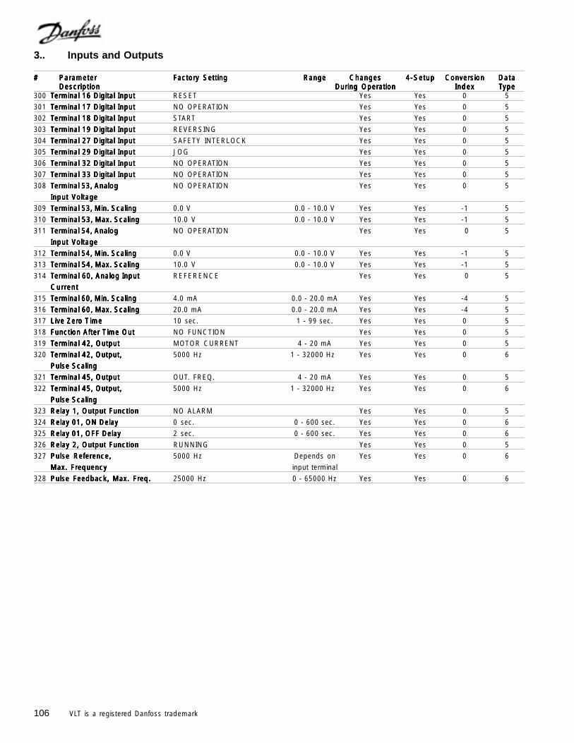
106 VLT is a registered Danfoss trademark
3.. Inputs and Outputs
##### ParameterParameterParameterParameterParameter Factory SettingFactory SettingFactory SettingFactory SettingFactory Setting RangeRangeRangeRangeRange ChangesChangesChangesChangesChanges 4-Setup4-Setup4-Setup4-Setup4-Setup ConversionConversionConversionConversionConversion DataDataDataDataDataDescriptionDescriptionDescriptionDescriptionDescription During OperationDuring OperationDuring OperationDuring OperationDuring Operation IndexIndexIndexIndexIndex TTTTTypeypeypeypeype
300 TTTTTerminal 16 Digital Inputerminal 16 Digital Inputerminal 16 Digital Inputerminal 16 Digital Inputerminal 16 Digital Input RESET Yes Yes 0 5
301 TTTTTerminal 17 Digital Inputerminal 17 Digital Inputerminal 17 Digital Inputerminal 17 Digital Inputerminal 17 Digital Input NO OPERATION Yes Yes 0 5
302 TTTTTerminal 18 Digital Inputerminal 18 Digital Inputerminal 18 Digital Inputerminal 18 Digital Inputerminal 18 Digital Input START Yes Yes 0 5
303 TTTTTerminal 19 Digital Inputerminal 19 Digital Inputerminal 19 Digital Inputerminal 19 Digital Inputerminal 19 Digital Input REVERSING Yes Yes 0 5
304 TTTTTerminal 27 Digital Inputerminal 27 Digital Inputerminal 27 Digital Inputerminal 27 Digital Inputerminal 27 Digital Input SAFETY INTERLOCK Yes Yes 0 5
305 TTTTTerminal 29 Digital Inputerminal 29 Digital Inputerminal 29 Digital Inputerminal 29 Digital Inputerminal 29 Digital Input JOG Yes Yes 0 5
306 TTTTTerminal 32 Digital Inputerminal 32 Digital Inputerminal 32 Digital Inputerminal 32 Digital Inputerminal 32 Digital Input NO OPERATION Yes Yes 0 5
307 TTTTTerminal 33 Digital Inputerminal 33 Digital Inputerminal 33 Digital Inputerminal 33 Digital Inputerminal 33 Digital Input NO OPERATION Yes Yes 0 5
308 TTTTTerminal 53, Analogerminal 53, Analogerminal 53, Analogerminal 53, Analogerminal 53, Analog NO OPERATION Yes Yes 0 5
IIIIInputnputnputnputnput Voltage Voltage Voltage Voltage Voltage
309 TTTTTerminal 53, Min. Scalingerminal 53, Min. Scalingerminal 53, Min. Scalingerminal 53, Min. Scalingerminal 53, Min. Scaling 0.0 V 0.0 - 10.0 V Yes Yes -1 5
310 TTTTTerminal 53, Max. Scalingerminal 53, Max. Scalingerminal 53, Max. Scalingerminal 53, Max. Scalingerminal 53, Max. Scaling 10.0 V 0.0 - 10.0 V Yes Yes -1 5
311 TTTTTerminal 54, Analogerminal 54, Analogerminal 54, Analogerminal 54, Analogerminal 54, Analog NO OPERATION Yes Yes 0 5
IIIIInputnputnputnputnput Voltage Voltage Voltage Voltage Voltage
312 TTTTTerminal 54, Min. Scalingerminal 54, Min. Scalingerminal 54, Min. Scalingerminal 54, Min. Scalingerminal 54, Min. Scaling 0.0 V 0.0 - 10.0 V Yes Yes -1 5
313 TTTTTerminal 54, Max. Scalingerminal 54, Max. Scalingerminal 54, Max. Scalingerminal 54, Max. Scalingerminal 54, Max. Scaling 10.0 V 0.0 - 10.0 V Yes Yes -1 5
314 TTTTTerminal 60, Analog Inputerminal 60, Analog Inputerminal 60, Analog Inputerminal 60, Analog Inputerminal 60, Analog Input REFERENCE Yes Yes 0 5
CurrentCurrentCurrentCurrentCurrent
315 TTTTTerminal 60, Min. Scalingerminal 60, Min. Scalingerminal 60, Min. Scalingerminal 60, Min. Scalingerminal 60, Min. Scaling 4.0 mA 0.0 - 20.0 mA Yes Yes -4 5
316 TTTTTerminal 60, Max. Scalingerminal 60, Max. Scalingerminal 60, Max. Scalingerminal 60, Max. Scalingerminal 60, Max. Scaling 20.0 mA 0.0 - 20.0 mA Yes Yes -4 5
317 Live ZerLive ZerLive ZerLive ZerLive Zero To To To To T imeimeimeimeime 10 sec. 1 - 99 sec. Yes Yes 0 5
318 Function After TFunction After TFunction After TFunction After TFunction After Time Outime Outime Outime Outime Out NO FUNCTION Yes Yes 0 5
319 TTTTTerminal 42, Outputerminal 42, Outputerminal 42, Outputerminal 42, Outputerminal 42, Output MOTOR CURRENT 4 - 20 mA Yes Yes 0 5
320 TTTTTerminal 42, Output,erminal 42, Output,erminal 42, Output,erminal 42, Output,erminal 42, Output, 5000 Hz 1 - 32000 Hz Yes Yes 0 6
Pulse ScalingPulse ScalingPulse ScalingPulse ScalingPulse Scaling
321 TTTTTerminal 45, Outputerminal 45, Outputerminal 45, Outputerminal 45, Outputerminal 45, Output OUT. FREQ. 4 - 20 mA Yes Yes 0 5
322 TTTTTerminal 45, Output,erminal 45, Output,erminal 45, Output,erminal 45, Output,erminal 45, Output, 5000 Hz 1 - 32000 Hz Yes Yes 0 6
Pulse ScalingPulse ScalingPulse ScalingPulse ScalingPulse Scaling
323 Relay 1, Output FunctionRelay 1, Output FunctionRelay 1, Output FunctionRelay 1, Output FunctionRelay 1, Output Function NO ALARM Yes Yes 0 5
324 Relay 01, ON DelayRelay 01, ON DelayRelay 01, ON DelayRelay 01, ON DelayRelay 01, ON Delay 0 sec. 0 - 600 sec. Yes Yes 0 6
325 Relay 01, OFF DelayRelay 01, OFF DelayRelay 01, OFF DelayRelay 01, OFF DelayRelay 01, OFF Delay 2 sec. 0 - 600 sec. Yes Yes 0 6
326 Relay 2, Output FunctionRelay 2, Output FunctionRelay 2, Output FunctionRelay 2, Output FunctionRelay 2, Output Function RUNNING Yes Yes 0 5
327 Pulse Reference,Pulse Reference,Pulse Reference,Pulse Reference,Pulse Reference, 5000 Hz Depends on Yes Yes 0 6
Max. FrequencyMax. FrequencyMax. FrequencyMax. FrequencyMax. Frequency input terminal
328 Pulse Feedback, Max. Freq.Pulse Feedback, Max. Freq.Pulse Feedback, Max. Freq.Pulse Feedback, Max. Freq.Pulse Feedback, Max. Freq. 25000 Hz 0 - 65000 Hz Yes Yes 0 6
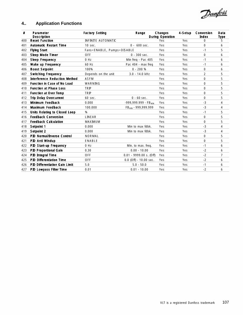
107VLT is a registered Danfoss trademark
4.. Application Functions
# # # # # ParameterParameterParameterParameterParameter Factory SettingFactory SettingFactory SettingFactory SettingFactory Setting RangeRangeRangeRangeRange ChangesChangesChangesChangesChanges 4-Setup4-Setup4-Setup4-Setup4-Setup ConversionConversionConversionConversionConversion DataDataDataDataDataDescriptionDescriptionDescriptionDescriptionDescription During OperationDuring OperationDuring OperationDuring OperationDuring Operation IndexIndexIndexIndexIndex TTTTTypeypeypeypeype
400 Reset FunctionReset FunctionReset FunctionReset FunctionReset Function INFINITE AUTOMATIC Yes Yes 0 5
401 Automatic Restart TAutomatic Restart TAutomatic Restart TAutomatic Restart TAutomatic Restart Timeimeimeimeime 10 sec. 0 - 600 sec. Yes Yes 0 6
402 Flying StartFlying StartFlying StartFlying StartFlying Start Fans=ENABLE, Pumps=DISABLE Yes Yes -1 5
403 Sleep Mode TSleep Mode TSleep Mode TSleep Mode TSleep Mode Timerimerimerimerimer OFF 0 - 300 sec. Yes Yes 0 6
404 Sleep FrequencySleep FrequencySleep FrequencySleep FrequencySleep Frequency 0 Hz Min freq - Par. 405 Yes Yes -1 6
405 Wake up FrequencyWake up FrequencyWake up FrequencyWake up FrequencyWake up Frequency 60 Hz Par. 404 - max freq Yes Yes -1 6
406 Boost SetpointBoost SetpointBoost SetpointBoost SetpointBoost Setpoint 100% 0 - 200 % Yes Yes 0 6
407 Switching FrequencySwitching FrequencySwitching FrequencySwitching FrequencySwitching Frequency Depends on the unit 3.0 - 14.0 kHz Yes Yes 2 5
408 Interference Reduction MethodInterference Reduction MethodInterference Reduction MethodInterference Reduction MethodInterference Reduction Method ASFM Yes Yes 0 5
409 Function in Case of No LoadFunction in Case of No LoadFunction in Case of No LoadFunction in Case of No LoadFunction in Case of No Load WARNING Yes Yes 0 5
410 Function at Phase LossFunction at Phase LossFunction at Phase LossFunction at Phase LossFunction at Phase Loss TRIP Yes Yes 0 5
411 Function at Over TFunction at Over TFunction at Over TFunction at Over TFunction at Over Tempempempempemp TRIP Yes Yes 0 5
412 TTTTTrip Delay Overrip Delay Overrip Delay Overrip Delay Overrip Delay Overcurrcurrcurrcurrcurrententententent 60 sec. 0 - 60 sec. Yes Yes 0 5
413 Minimum FeedbackMinimum FeedbackMinimum FeedbackMinimum FeedbackMinimum Feedback 0.000 -999,999.999 - FBMIN Yes Yes -3 4
414 Maximum FeedbackMaximum FeedbackMaximum FeedbackMaximum FeedbackMaximum Feedback 100.000 FBMIN - 999,999.999 Yes Yes -3 4
415 Units Relating to Closed LoopUnits Relating to Closed LoopUnits Relating to Closed LoopUnits Relating to Closed LoopUnits Relating to Closed Loop % Yes Yes -1 5
416 Feedback ConversionFeedback ConversionFeedback ConversionFeedback ConversionFeedback Conversion LINEAR Yes Yes 0 5
417 Feedback CalculationFeedback CalculationFeedback CalculationFeedback CalculationFeedback Calculation MAXIMUM Yes Yes 0 5
418 Setpoint 1Setpoint 1Setpoint 1Setpoint 1Setpoint 1 0.000 Min to max fdbk. Yes Yes -3 4
419 Setpoint 2Setpoint 2Setpoint 2Setpoint 2Setpoint 2 0.000 Min to max fdbk. Yes Yes -3 4
420 PID Normal/Inverse ControlPID Normal/Inverse ControlPID Normal/Inverse ControlPID Normal/Inverse ControlPID Normal/Inverse Control NORMAL Yes Yes 0 5
421 PID Anti WPID Anti WPID Anti WPID Anti WPID Anti Windupindupindupindupindup ENABLE Yes Yes 0 5
422 PID Start-up FrequencyPID Start-up FrequencyPID Start-up FrequencyPID Start-up FrequencyPID Start-up Frequency 0 Hz Min. to max. freq. Yes Yes -1 6
423 PID Proportional GainPID Proportional GainPID Proportional GainPID Proportional GainPID Proportional Gain 0.30 0.00 - 10.00 Yes Yes -2 6
424 PID Integral TPID Integral TPID Integral TPID Integral TPID Integral Timeimeimeimeime OFF 0.01 - 9999.00 s. (Off) Yes Yes -2 7
425 PID DifPID DifPID DifPID DifPID Differferferferferentiation Tentiation Tentiation Tentiation Tentiation Timeimeimeimeime OFF 0.0 (Off) - 10.00 sec. Yes Yes -2 6
426 PID Differentiation Gain LimitPID Differentiation Gain LimitPID Differentiation Gain LimitPID Differentiation Gain LimitPID Differentiation Gain Limit 5.0 5.0 - 50.0 Yes Yes -1 6
427 PID Lowpass Filter TPID Lowpass Filter TPID Lowpass Filter TPID Lowpass Filter TPID Lowpass Filter Timeimeimeimeime 0.01 0.01 - 10.00 Yes Yes -2 6
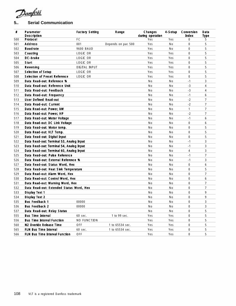
108 VLT is a registered Danfoss trademark
5.. Serial Communication
# # # # # ParameterParameterParameterParameterParameter Factory SettingFactory SettingFactory SettingFactory SettingFactory Setting RangeRangeRangeRangeRange ChangesChangesChangesChangesChanges 4-Setup4-Setup4-Setup4-Setup4-Setup ConversionConversionConversionConversionConversion DataDataDataDataDataDescriptionDescriptionDescriptionDescriptionDescription during operationduring operationduring operationduring operationduring operation IndexIndexIndexIndexIndex TTTTTypeypeypeypeype
500 ProtocolProtocolProtocolProtocolProtocol FC Yes Yes 0 5
501 AddressAddressAddressAddressAddress 001 Depends on par. 500 Yes No 0 5
502 BaudrateBaudrateBaudrateBaudrateBaudrate 9600 BAUD Yes No 0 5
503 CoastingCoastingCoastingCoastingCoasting LOGIC OR Yes Yes 0 5
504 DC-brakeDC-brakeDC-brakeDC-brakeDC-brake LOGIC OR Yes Yes 0 5
505 StartStartStartStartStart LOGIC OR Yes Yes 0 5
506 ReversingReversingReversingReversingReversing DIGITAL INPUT Yes Yes 0 5
507 Selection of SetupSelection of SetupSelection of SetupSelection of SetupSelection of Setup LOGIC OR Yes Yes 0 5
508 Selection of Preset ReferenceSelection of Preset ReferenceSelection of Preset ReferenceSelection of Preset ReferenceSelection of Preset Reference LOGIC OR Yes Yes 0 5
509 Data Read-out: Reference %Data Read-out: Reference %Data Read-out: Reference %Data Read-out: Reference %Data Read-out: Reference % No No -1 3
510 Data Read-out: Reference UnitData Read-out: Reference UnitData Read-out: Reference UnitData Read-out: Reference UnitData Read-out: Reference Unit No No -3 4
511 Data Read-out: FeedbackData Read-out: FeedbackData Read-out: FeedbackData Read-out: FeedbackData Read-out: Feedback No No -3 4
512 Data Read-out: FrequencyData Read-out: FrequencyData Read-out: FrequencyData Read-out: FrequencyData Read-out: Frequency No No -1 6
513 User Defined Read-outUser Defined Read-outUser Defined Read-outUser Defined Read-outUser Defined Read-out No No -2 7
514 Data Read-out: CurrentData Read-out: CurrentData Read-out: CurrentData Read-out: CurrentData Read-out: Current No No -2 7
515 Data Read-out: PowerData Read-out: PowerData Read-out: PowerData Read-out: PowerData Read-out: Power, kW, kW, kW, kW, kW No No 1 7
516 Data Read-out: PowerData Read-out: PowerData Read-out: PowerData Read-out: PowerData Read-out: Power, HP, HP, HP, HP, HP No No -2 7
517 Data Read-out: Motor VoltageData Read-out: Motor VoltageData Read-out: Motor VoltageData Read-out: Motor VoltageData Read-out: Motor Voltage No No -1 6
518 Data Read-out: DC Link VoltageData Read-out: DC Link VoltageData Read-out: DC Link VoltageData Read-out: DC Link VoltageData Read-out: DC Link Voltage No No 0 6
519 Data Read-out: Motor temp.Data Read-out: Motor temp.Data Read-out: Motor temp.Data Read-out: Motor temp.Data Read-out: Motor temp. No No 0 5
520 Data Read-out: VLData Read-out: VLData Read-out: VLData Read-out: VLData Read-out: VLT TT TT TT TT Temp.emp.emp.emp.emp. No No 0 5
521 Data Read-out: Digital InputData Read-out: Digital InputData Read-out: Digital InputData Read-out: Digital InputData Read-out: Digital Input No No 0 5
522 Data Read-out: TData Read-out: TData Read-out: TData Read-out: TData Read-out: Terminal 53, Analog Inputerminal 53, Analog Inputerminal 53, Analog Inputerminal 53, Analog Inputerminal 53, Analog Input No No -1 3
523 Data Read-out: TData Read-out: TData Read-out: TData Read-out: TData Read-out: Terminal 54, Analog Inputerminal 54, Analog Inputerminal 54, Analog Inputerminal 54, Analog Inputerminal 54, Analog Input No No -1 3
524 Data Read-out: TData Read-out: TData Read-out: TData Read-out: TData Read-out: Terminal 60, Analog Inputerminal 60, Analog Inputerminal 60, Analog Inputerminal 60, Analog Inputerminal 60, Analog Input No No 4 3
525 Data Read-out: Pulse ReferenceData Read-out: Pulse ReferenceData Read-out: Pulse ReferenceData Read-out: Pulse ReferenceData Read-out: Pulse Reference No No -1 7
526 Data Read-out: External Reference %Data Read-out: External Reference %Data Read-out: External Reference %Data Read-out: External Reference %Data Read-out: External Reference % No No -1 3
527 Data Read-out: Status Word, HexData Read-out: Status Word, HexData Read-out: Status Word, HexData Read-out: Status Word, HexData Read-out: Status Word, Hex No No 0 6
528 Data Read-out: Heat Sink TData Read-out: Heat Sink TData Read-out: Heat Sink TData Read-out: Heat Sink TData Read-out: Heat Sink Temperaturemperaturemperaturemperaturemperatureeeee No No 0 5
529 Data Read-out: Alarm Word, HexData Read-out: Alarm Word, HexData Read-out: Alarm Word, HexData Read-out: Alarm Word, HexData Read-out: Alarm Word, Hex No No 0 7
530 Data Read-out: Control Word, HexData Read-out: Control Word, HexData Read-out: Control Word, HexData Read-out: Control Word, HexData Read-out: Control Word, Hex No No 0 6
531 Data Read-out: Warning Word, HexData Read-out: Warning Word, HexData Read-out: Warning Word, HexData Read-out: Warning Word, HexData Read-out: Warning Word, Hex No No 0 7
532 Data Read-out: Extended Status Word, HexData Read-out: Extended Status Word, HexData Read-out: Extended Status Word, HexData Read-out: Extended Status Word, HexData Read-out: Extended Status Word, Hex No No 0 7
533 Display TDisplay TDisplay TDisplay TDisplay Text 1ext 1ext 1ext 1ext 1 No No 0 9
534 Display TDisplay TDisplay TDisplay TDisplay Text 2ext 2ext 2ext 2ext 2 No No 0 9
535 Bus Feedback 1Bus Feedback 1Bus Feedback 1Bus Feedback 1Bus Feedback 1 00000 No No 0 3
536 Bus Feedback 2Bus Feedback 2Bus Feedback 2Bus Feedback 2Bus Feedback 2 00000 No No 0 3
537 Data Read-out: Relay StatusData Read-out: Relay StatusData Read-out: Relay StatusData Read-out: Relay StatusData Read-out: Relay Status No No 0 5
555 Bus TBus TBus TBus TBus Time Intervalime Intervalime Intervalime Intervalime Interval 60 sec. 1 to 99 sec. Yes Yes 0 5
556 Bus TBus TBus TBus TBus Time Interval Functionime Interval Functionime Interval Functionime Interval Functionime Interval Function NO FUNCTION Yes Yes 0 5
560 N2 Overide Release TN2 Overide Release TN2 Overide Release TN2 Overide Release TN2 Overide Release Timeimeimeimeime OFF 1 to 65534 sec. Yes Yes 0 5
565 FLN Bus TFLN Bus TFLN Bus TFLN Bus TFLN Bus Time Intervalime Intervalime Intervalime Intervalime Interval 60 sec. 1 to 65534 sec. Yes Yes 0 5
566 FLN Bus TFLN Bus TFLN Bus TFLN Bus TFLN Bus Time Interval Functionime Interval Functionime Interval Functionime Interval Functionime Interval Function OFF Yes Yes 0 5
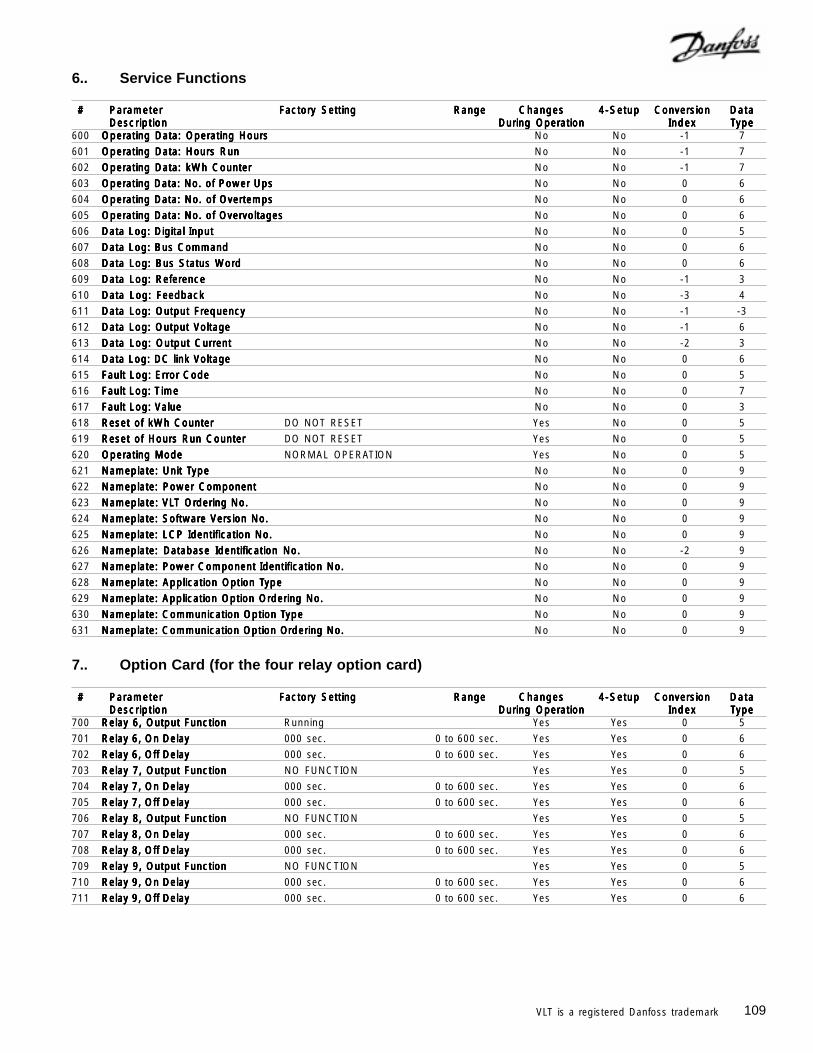
109VLT is a registered Danfoss trademark
6.. Service Functions
# # # # # ParameterParameterParameterParameterParameter Factory SettingFactory SettingFactory SettingFactory SettingFactory Setting RangeRangeRangeRangeRange ChangesChangesChangesChangesChanges 4-Setup4-Setup4-Setup4-Setup4-Setup ConversionConversionConversionConversionConversion DataDataDataDataDataDescriptionDescriptionDescriptionDescriptionDescription During OperationDuring OperationDuring OperationDuring OperationDuring Operation IndexIndexIndexIndexIndex TTTTTypeypeypeypeype
600 Operating Data: Operating HoursOperating Data: Operating HoursOperating Data: Operating HoursOperating Data: Operating HoursOperating Data: Operating Hours No No -1 7
601 Operating Data: Hours RunOperating Data: Hours RunOperating Data: Hours RunOperating Data: Hours RunOperating Data: Hours Run No No -1 7
602 Operating Data: kWh CounterOperating Data: kWh CounterOperating Data: kWh CounterOperating Data: kWh CounterOperating Data: kWh Counter No No -1 7
603 Operating Data: No. of Power UpsOperating Data: No. of Power UpsOperating Data: No. of Power UpsOperating Data: No. of Power UpsOperating Data: No. of Power Ups No No 0 6
604 Operating Data: No. of OvertempsOperating Data: No. of OvertempsOperating Data: No. of OvertempsOperating Data: No. of OvertempsOperating Data: No. of Overtemps No No 0 6
605 Operating Data: No. of OvervoltagesOperating Data: No. of OvervoltagesOperating Data: No. of OvervoltagesOperating Data: No. of OvervoltagesOperating Data: No. of Overvoltages No No 0 6
606 Data Log: Digital InputData Log: Digital InputData Log: Digital InputData Log: Digital InputData Log: Digital Input No No 0 5
607 Data Log: Bus CommandData Log: Bus CommandData Log: Bus CommandData Log: Bus CommandData Log: Bus Command No No 0 6
608 Data Log: Bus Status WordData Log: Bus Status WordData Log: Bus Status WordData Log: Bus Status WordData Log: Bus Status Word No No 0 6
609 Data Log: ReferenceData Log: ReferenceData Log: ReferenceData Log: ReferenceData Log: Reference No No -1 3
610 Data Log: FeedbackData Log: FeedbackData Log: FeedbackData Log: FeedbackData Log: Feedback No No -3 4
611 Data Log: Output FrequencyData Log: Output FrequencyData Log: Output FrequencyData Log: Output FrequencyData Log: Output Frequency No No -1 -3
612 Data Log: Output VoltageData Log: Output VoltageData Log: Output VoltageData Log: Output VoltageData Log: Output Voltage No No -1 6
613 Data Log: Output CurrentData Log: Output CurrentData Log: Output CurrentData Log: Output CurrentData Log: Output Current No No -2 3
614 Data Log: DC link VoltageData Log: DC link VoltageData Log: DC link VoltageData Log: DC link VoltageData Log: DC link Voltage No No 0 6
615 Fault Log: Error CodeFault Log: Error CodeFault Log: Error CodeFault Log: Error CodeFault Log: Error Code No No 0 5
616 Fault Log: TFault Log: TFault Log: TFault Log: TFault Log: Timeimeimeimeime No No 0 7
617 Fault Log: ValueFault Log: ValueFault Log: ValueFault Log: ValueFault Log: Value No No 0 3
618 Reset of kWh CounterReset of kWh CounterReset of kWh CounterReset of kWh CounterReset of kWh Counter DO NOT RESET Yes No 0 5
619 Reset of Hours Run CounterReset of Hours Run CounterReset of Hours Run CounterReset of Hours Run CounterReset of Hours Run Counter DO NOT RESET Yes No 0 5
620 Operating ModeOperating ModeOperating ModeOperating ModeOperating Mode NORMAL OPERATION Yes No 0 5
621 Nameplate: Unit TNameplate: Unit TNameplate: Unit TNameplate: Unit TNameplate: Unit Typeypeypeypeype No No 0 9
622 Nameplate: Power ComponentNameplate: Power ComponentNameplate: Power ComponentNameplate: Power ComponentNameplate: Power Component No No 0 9
623 Nameplate: VLNameplate: VLNameplate: VLNameplate: VLNameplate: VLT OrT OrT OrT OrT Ordering No.dering No.dering No.dering No.dering No. No No 0 9
624 Nameplate: Software Version No.Nameplate: Software Version No.Nameplate: Software Version No.Nameplate: Software Version No.Nameplate: Software Version No. No No 0 9
625 Nameplate: LCP Identification No.Nameplate: LCP Identification No.Nameplate: LCP Identification No.Nameplate: LCP Identification No.Nameplate: LCP Identification No. No No 0 9
626 Nameplate: Database Identification No.Nameplate: Database Identification No.Nameplate: Database Identification No.Nameplate: Database Identification No.Nameplate: Database Identification No. No No -2 9
627 Nameplate: Power Component Nameplate: Power Component Nameplate: Power Component Nameplate: Power Component Nameplate: Power Component Identification No.Identification No.Identification No.Identification No.Identification No. No No 0 9
628 Nameplate: Application Option TNameplate: Application Option TNameplate: Application Option TNameplate: Application Option TNameplate: Application Option Typeypeypeypeype No No 0 9
629 Nameplate: Application Option Ordering No.Nameplate: Application Option Ordering No.Nameplate: Application Option Ordering No.Nameplate: Application Option Ordering No.Nameplate: Application Option Ordering No. No No 0 9
630 Nameplate: Communication Option TNameplate: Communication Option TNameplate: Communication Option TNameplate: Communication Option TNameplate: Communication Option Typeypeypeypeype No No 0 9
631 Nameplate: Communication Option ONameplate: Communication Option ONameplate: Communication Option ONameplate: Communication Option ONameplate: Communication Option Ordering No.rdering No.rdering No.rdering No.rdering No. No No 0 9
7.. Option Card (for the four relay option card)
# # # # # ParameterParameterParameterParameterParameter Factory SettingFactory SettingFactory SettingFactory SettingFactory Setting RangeRangeRangeRangeRange ChangesChangesChangesChangesChanges 4-Setup4-Setup4-Setup4-Setup4-Setup ConversionConversionConversionConversionConversion DataDataDataDataDataDescriptionDescriptionDescriptionDescriptionDescription During OperationDuring OperationDuring OperationDuring OperationDuring Operation IndexIndexIndexIndexIndex TTTTTypeypeypeypeype
700 Relay 6, Output FunctionRelay 6, Output FunctionRelay 6, Output FunctionRelay 6, Output FunctionRelay 6, Output Function Running Yes Yes 0 5
701 Relay 6, On DelayRelay 6, On DelayRelay 6, On DelayRelay 6, On DelayRelay 6, On Delay 000 sec. 0 to 600 sec. Yes Yes 0 6
702 Relay 6, Off DelayRelay 6, Off DelayRelay 6, Off DelayRelay 6, Off DelayRelay 6, Off Delay 000 sec. 0 to 600 sec. Yes Yes 0 6
703 Relay 7, Output FunctionRelay 7, Output FunctionRelay 7, Output FunctionRelay 7, Output FunctionRelay 7, Output Function NO FUNCTION Yes Yes 0 5
704 Relay 7, On DelayRelay 7, On DelayRelay 7, On DelayRelay 7, On DelayRelay 7, On Delay 000 sec. 0 to 600 sec. Yes Yes 0 6
705 Relay 7, Off DelayRelay 7, Off DelayRelay 7, Off DelayRelay 7, Off DelayRelay 7, Off Delay 000 sec. 0 to 600 sec. Yes Yes 0 6
706 Relay 8, Output FunctionRelay 8, Output FunctionRelay 8, Output FunctionRelay 8, Output FunctionRelay 8, Output Function NO FUNCTION Yes Yes 0 5
707 Relay 8, On DelayRelay 8, On DelayRelay 8, On DelayRelay 8, On DelayRelay 8, On Delay 000 sec. 0 to 600 sec. Yes Yes 0 6
708 Relay 8, Off DelayRelay 8, Off DelayRelay 8, Off DelayRelay 8, Off DelayRelay 8, Off Delay 000 sec. 0 to 600 sec. Yes Yes 0 6
709 Relay 9, Output FunctionRelay 9, Output FunctionRelay 9, Output FunctionRelay 9, Output FunctionRelay 9, Output Function NO FUNCTION Yes Yes 0 5
710 Relay 9, On DelayRelay 9, On DelayRelay 9, On DelayRelay 9, On DelayRelay 9, On Delay 000 sec. 0 to 600 sec. Yes Yes 0 6
711 Relay 9, Off DelayRelay 9, Off DelayRelay 9, Off DelayRelay 9, Off DelayRelay 9, Off Delay 000 sec. 0 to 600 sec. Yes Yes 0 6
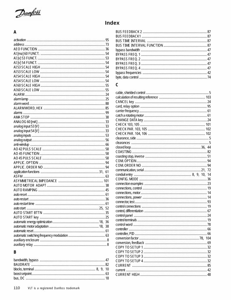
110 VLT is a registered Danfoss trademark
Index
A
activation .......................................................................................... 95address ............................................................................................ 73AEO FUNCTION ............................................................................. 36AI [ma] 60 FUNCT. .......................................................................... 54AI [v] 53 FUNCT. ............................................................................. 53AI [v] 54 FUNCT. ............................................................................. 54AI 53 SCALE HIGH .......................................................................... 54AI 53 SCALE LOW ........................................................................... 54AI 54 SCALE HIGH .......................................................................... 54AI 54 SCALE LOW ........................................................................... 54AI 60 SCALE HIGH .......................................................................... 55AI 60 SCALE LOW ........................................................................... 55ALARM ............................................................................................ 24alarm lamp ....................................................................................... 25alarm word ....................................................................................... 88ALARM WORD, HEX ....................................................................... 85alarms .............................................................................................. 99AMA STOP ...................................................................................... 38ANALOG 60 [mA] ............................................................................. 33analog input 53 [V] ........................................................................... 33analog input 54 [V] ........................................................................... 33analog inputs .................................................................................... 53analog output .................................................................................... 56anti-windup ...................................................................................... 66AO 42 PULS SCALE ........................................................................ 58AO 45 FUNCTION ........................................................................... 58AO 45 PULS SCALE ........................................................................ 58APPLIC. OPTION ............................................................................ 94APPLIC. ORDER NO ....................................................................... 94application functions ................................................................... 31, 61ASFM .............................................................................................. 63ASYMMETRICAL IMPEDANCE .................................................... 101AUTO MOTOR ADAPT ................................................................... 38AUTO RAMPING ............................................................................. 45auto reset ......................................................................................... 61auto restart ....................................................................................... 36auto restart time ................................................................................ 61auto start ................................................................................... 25, 52AUTO START BTTN ....................................................................... 35AUTO START key ........................................................................... 25automatic energy optimization ..................................................... 18, 36automatic motor adaptation ......................................................... 18, 38automatic reset .................................................................................. 61automatic switching frequency modulation .......................................... 63auxiliary enclosure ............................................................................. 8auxiliary relay .................................................................................... 8
B
bandwidth, bypass ........................................................................... 47BAUDRATE ..................................................................................... 82blocks, terminal ...................................................................... 8, 9, 10boost setpoint .................................................................................... 63bus, DC ........................................................................................... 18
BUS FEEDBACK 2 .......................................................................... 87BUS FEEDBACK1 ........................................................................... 87BUS TIME INTERVAL ..................................................................... 87BUS TIME INTERVAL FUNCTION .................................................. 87bypass bandwidth ............................................................................ 47BYPASS FREQ. 1 ............................................................................ 47BYPASS FREQ. 2 ............................................................................ 47BYPASS FREQ. 3 ............................................................................ 47BYPASS FREQ. 4 ............................................................................ 47bypass frequencies .......................................................................... 42byte, data control .............................................................................. 74
C
cable, shielded control ........................................................................ 5calculation of resulting reference ..................................................... 103CANCEL key ................................................................................... 24card, relay option ............................................................................. 95carrier frequency .............................................................................. 61catch a rotating motor ........................................................................ 61CHANGE DATA key ......................................................................... 24CHECK 103, 105 ........................................................................... 101CHECK PAR. 103, 105 .................................................................. 102CHECK PAR. 104, 106 .................................................................. 102clearance, side ................................................................................... 5clearances ......................................................................................... 5closed loop ................................................................................ 36, 44COASTING ...................................................................................... 82coasting stop, inverse ....................................................................... 51COM. OPTION ................................................................................. 94COM. ORDER NO ........................................................................... 94communication, serial ................................................................. 21, 72conduit entry .................................................................. 8, 9, 10, 14CONFIG. MODE .............................................................................. 36connection examples ........................................................................ 23connections, control .......................................................................... 19connections, motor ............................................................................ 14connections, power .......................................................................... 14connector, test ................................................................................... 93control connections ........................................................................... 19control, differentiation ........................................................................ 67control panel .................................................................................... 24control terminals ................................................................................ 19control word ..................................................................................... 78controller .......................................................................................... 66controller, PID ................................................................................... 66conversion factor ..................................................................... 78, 104conversion, feedback ....................................................................... 69COPY TO SETUP 1 ......................................................................... 32COPY TO SETUP 2 ......................................................................... 32COPY TO SETUP 3 ......................................................................... 32COPY TO SETUP 4 ......................................................................... 32CURRENT ...................................................................................... 85current ............................................................................................. 42CURRENT HIGH ............................................................................. 48
111VLT is a registered Danfoss trademark
CURRENT LIMIT ............................................................................ 47CURRENT LOW .............................................................................. 48current, output .................................................................................. 47CUST. READ. UNIT ....................................................................... 33CUSTOM READOUT ............................................................... 33, 85
D
Danfoss FC protocol ......................................................................... 72DATA CHANGE LOCK ..................................................................... 35data change lock .............................................................................. 52data control byte ............................................................................... 74data, log ........................................................................................... 91DC BRAKE ...................................................................................... 83DC BRAKE CURRENT .................................................................... 40DC BRAKE CUT-IN ......................................................................... 40DC brake cut-in frequency ................................................................ 40DC BRAKE TIME ............................................................................. 40DC braking current ........................................................................... 40DC braking, inverse ......................................................................... 51DC braking time ................................................................................ 40DC bus ............................................................................................ 18DC LINK VOLTAGE ......................................................................... 85DC VOLTAGE [V] ............................................................................. 33deactivation time ............................................................................... 95derivative ......................................................................................... 66differentiation control ......................................................................... 67differentiation time .............................................................................. 71differentiator ...................................................................................... 71DIGITAL INPUT ............................................................................... 85DIGITAL INPUT [BIN] ...................................................................... 33digital inputs ............................................................................... 19, 50DIP switches .................................................................................... 21DISABLE ......................................................................................... 35display, LCD .................................................................................... 24display modes ........................................................................... 24, 25DISPLAY TEXT ARRAY 1 ................................................................ 86DISPLAY TEXT ARRAY 2 ................................................................ 86disturbances, signal ............................................................................ 5download ......................................................................................... 32DOWNLOAD ALL PARAM. ............................................................... 32DOWNLOAD SIZE INDEP. ............................................................... 32drive type ......................................................................................... 94
E
electrical noise .................................................................................. 22electronic thermal protection .............................................................. 14electronic thermal relay ................................................................ 2, 14EMI .................................................................................................. 22EMI filter ........................................................................................... 22ENABLE .......................................................................................... 35enclosure, auxiliary ............................................................................ 8ENERGY [UNIT] .............................................................................. 33entry, conduit .................................................................. 8, 9, 10, 14error code ........................................................................................ 76ETR ................................................................................................. 41examples, connection ....................................................................... 23
EXT. REFERENCE [%] ................................................................... 33EXTEND MENU .............................................................................. 24extend menu key .............................................................................. 31extended status word ....................................................................... 88EXTERNAL REFERENCE ............................................................... 85
F
F. LOG: ERROR CODE ................................................................... 92F. LOG: TIME ................................................................................... 92F. LOG: VALUE ................................................................................ 92factory settings ................................................................................ 104factory setup ..................................................................................... 31FC protocol ...................................................................................... 82FEEDBACK ..................................................................................... 85feedback .......................................................................................... 42FEEDBACK 1 [UNITS] .................................................................... 33FEEDBACK 2 [UNITS] .................................................................... 33feedback [units] ................................................................................. 33FEEDBACK CONV. ......................................................................... 69feedback conversion ........................................................................ 69FEEDBACK HIGH ........................................................................... 49FEEDBACK LOW ............................................................................. 49feedback signal .......................................................................... 66, 67feedback signals ............................................................................... 65filter, EMI .......................................................................................... 22filter, LC ............................................................................................ 38filter, lowpass ............................................................................. 67, 71final adjustments ................................................................................ 30fixed switching frequency .................................................................. 63FLA .................................................................................................. 37FLN ................................................................................................. 72flow .................................................................................................. 69flying start ......................................................................................... 61freeze output .................................................................................... 51freeze reference ............................................................................... 51frequencies, bypass ......................................................................... 42FREQUENCY .................................................................................. 85FREQUENCY [%] ........................................................................... 33FREQUENCY [HZ] .......................................................................... 33frequency, bypass bandwidth ........................................................... 47frequency, carrier ............................................................................. 61frequency, fixed switching ................................................................. 63FREQUENCY LOW ......................................................................... 48frequency, present output .................................................................. 81FREQUENCY RANGE..................................................................... 42frequency, switching ......................................................................... 63full load current rating ....................................................................... 37FUNCT. LOW CURR. ...................................................................... 63fuses, input ......................................................................................... 7fuses, internal drive ............................................................................ 7
G
galvanic isolation .............................................................................. 22ground leakage current .................................................................... 22ground terminals ............................................................................... 15grounding ........................................................................................ 14grounding plate .................................................................................. 5
112 VLT is a registered Danfoss trademark
H
hand start .................................................................................. 25, 52HAND START BTTN ....................................................................... 35HEATSINK TEMP ..................................................................... 33, 85high breakaway torque..................................................................... 39HIGH START TORQ. ....................................................................... 39high-voltage relay ............................................................................ 18HOURS RUN ................................................................................... 33
I
initialization ....................................................................................... 29initialization, manual .......................................................................... 29input fuses .......................................................................................... 7input power ........................................................................ 11, 12, 13inputs and outputs ...................................................................... 31, 50inputs, digital .............................................................................. 19, 50installation checks ............................................................................. 30integral ............................................................................................. 66integrator .......................................................................................... 71interference reduction ....................................................................... 61INTERNAL FAULT ......................................................................... 101INTERRUPTED BY USER ............................................................ 101inverse regulation ............................................................................. 66
J
jog ................................................................................................... 52JOG FREQUENCY .......................................................................... 45Johnson Controls Metasys N2 ................................................... 72, 82
K
key, extend menu ............................................................................. 31kWh COUNTER ............................................................................... 90
L
L1, L2 and L3 ..................................................................... 11, 12, 13lamp, alarm ...................................................................................... 25lamp, warning ................................................................................... 25language .......................................................................................... 28LARGE READOUT ......................................................................... 33LC filter ............................................................................................. 38LCD display ..................................................................................... 24LCP copy ......................................................................................... 32LCP ID NO. ..................................................................................... 94leads, motor ..................................................................................... 11LED, power on ................................................................................. 25LIMIT VALUE FAULT ..................................................................... 101LIVE ZERO FUNCT. ........................................................................ 55LIVE ZERO TIME ............................................................................ 55load and motor .......................................................................... 31, 36load, loss of ...................................................................................... 61lock for data change ......................................................................... 24LOCKED .......................................................................................... 35log data ............................................................................................ 91log, digital input ................................................................................. 91
LOG: BUS COMMAND .................................................................... 91LOG: BUS STAT WD ........................................................................ 91LOG: DC LINK VOLT ....................................................................... 91LOG: FEEDBACK ............................................................................ 91LOG: MOTOR CURR. ..................................................................... 91LOG: MOTOR FREQ. ...................................................................... 91LOG: MOTOR VOLT ........................................................................ 91LOG: REFERENCE ......................................................................... 91loss of load ....................................................................................... 61LOW P 105 .................................................................................... 101lowpass filter .............................................................................. 67, 71
M
manual initialization ........................................................................... 29manual reset .................................................................................... 61MAX. FEEDBACK ............................................................................ 65MAX. FREQUENCY ........................................................................ 42MAX. REFERENCE ......................................................................... 44messages, status .............................................................................. 96metal grounding plate ....................................................................... 14Metasys N2 ...................................................................................... 82meters .............................................................................................. 25MIN. FEEDBACK ............................................................................. 65MIN. FREQUENCY ......................................................................... 42MIN. REFERENCE .......................................................................... 44minimum frequency ........................................................................... 28MOT. THERM PROTEC .................................................................. 41motor connections ............................................................................. 14MOTOR CURRENT ........................................................................ 37motor current .................................................................................... 28MOTOR CURRENT [A] ................................................................... 33MOTOR FREQUENCY .................................................................... 37motor frequency ............................................................................... 28motor leads ...................................................................................... 11MOTOR NOM. SPEED .................................................................... 38motor nominal speed ........................................................................ 28MOTOR POWER ............................................................................. 37motor power ..................................................................................... 28MOTOR PREHEAT .......................................................................... 39motor preheat ................................................................................... 39motor preheat DC current ................................................................. 39MOTOR ROTATES ........................................................................ 101MOTOR TEMPERATURE ................................................................ 85motor temperature ............................................................................ 41motor thermal protection .................................................................... 41MOTOR TOO BIG .......................................................................... 101MOTOR TOO SMALL .................................................................... 101MOTOR VOLT ................................................................................. 85MOTOR VOLTAGE .......................................................................... 37motor voltage............................................................................. 28, 33motor wiring ..................................................................................... 14motors, multiple ................................................................................. 14MULTI SETUP ................................................................................. 31multi-setup ........................................................................................ 31MULTIM.START VOLT..................................................................... 39MULTIPLE MOTORS ....................................................................... 36multiple motors ........................................................................... 14, 18
N
N2 ................................................................................................... 72nameplate ........................................................................................ 94National Electrical Code ...................................................................... 2NEC ................................................................................................... 2NEMA 1 ....................................................................................... 5, 8NEMA 12 ........................................................................................... 9NO AMA .......................................................................................... 38NO COPY ........................................................................................ 32noise, electrical ................................................................................. 22noise, radio frequency ........................................................................ 5NOISE REDUCTION ....................................................................... 63NOT LOCKED ................................................................................. 35
O
OFF/START key ....................................................................... 25, 35OFF/STOP ...................................................................................... 36OK ................................................................................................... 24ON ................................................................................................... 24OPEN LOOP .................................................................................... 36open loop .................................................................................. 36, 44OPERATING HOURS ...................................................................... 90operation and display ....................................................................... 31OPERATION MODE ........................................................................ 92operational tests — AUTO ................................................................ 30operational tests — HAND ................................................................ 30ORDERING NO ............................................................................... 94output current ................................................................................... 47output frequency high limit ................................................................. 42output frequency low limit .................................................................. 42output frequency range..................................................................... 42output signal ..................................................................................... 56OVER TEMPS ................................................................................. 90OVER VOLTS .................................................................................. 90OVERLOADDELAY .......................................................................... 64
P
parallel motors ........................................................................... 36, 39PARAM DB ID .................................................................................. 94Parameters
001 Language ............................................................................. 31002 Active Setup .......................................................................... 31003 Copying of Setups ................................................................. 32004 LCP Copy............................................................................. 32005 Maximum Value of User-defined Readout .............................. 33006 Unit for User Defined Readout ............................................... 33007 Large Display Readout ......................................................... 33008 Small Display Readout 1.1 .................................................... 34009 Small Display Readout 1.2 .................................................... 34010 Small Display Readout 1.3 .................................................... 35011 Unit of Local Reference .......................................................... 35012 Hand Start on LCP ................................................................ 35013 OFF/STOP on LCP (STOP BUTTON) .................................. 35014 Auto Start on LCP ................................................................. 35016 Lock for Data Change ........................................................... 35
017 Operating State at Power up, Local ........................................ 36100 Configuration ......................................................................... 36101 Torque Characteristics ........................................................... 36102 Motor Power ......................................................................... 37103 Motor Voltage ........................................................................ 37104 Motor Frequency .................................................................. 37105 Motor Current ....................................................................... 37106 Rated Motor Speed ............................................................... 38107 Automatic Motor Adaptation .................................................... 38107 Automatic Motor Adaptation, AMA .......................................... 38108 Start Voltage of Parallel Motors ............................................... 39109 Resonance Dampening ......................................................... 39110 High Breakaway Torque ....................................................... 39111 Start Delay ............................................................................. 39112 Motor Preheat ....................................................................... 39113 Motor Preheat DC Current .................................................... 39114 DC Braking Current ............................................................... 40115 DC Braking Time ................................................................... 40116 DC Brake Cut-in Frequency .................................................. 40117 Motor Thermal Protection ....................................................... 41200 Output Frequency Range ...................................................... 42201 Output Frequency Low Limit .................................................. 42202 Output Frequency High Limit ................................................. 42203 Reference Handling .............................................................. 43204 Minimum Reference............................................................... 44205 Maximum Reference ............................................................. 44206 Ramp Up Time ...................................................................... 45207 Ramp Down Time ................................................................. 45208 Automatic Ramp Up/Down ..................................................... 45209 Jog Frequency ..................................................................... 45210 Reference Type ................................................................... 46211 Preset Reference 1 ................................................................ 47212 Preset Reference 2 ............................................................... 47213 Preset Reference 3 ............................................................... 47214 Preset Reference 4 ............................................................... 47215 Current Limit .......................................................................... 47216 Frequency Bypass, Bandwidth .............................................. 47217 Frequency Bypass 1 ............................................................. 47218 Frequency Bypass 2 ............................................................. 47219 Frequency Bypass 3 ............................................................. 47220 Frequency Bypass 4 ............................................................. 47221 Warning: Low Current ........................................................... 48222 Warning: High Current .......................................................... 48223 Warning: Low Frequency ...................................................... 48224 Warning: High Frequency ..................................................... 48225 Warning: Low Reference ....................................................... 49226 Warning: High Reference ...................................................... 49227 Warning: Low Feedback ....................................................... 49228 Warning: High Feedback ....................................................... 49308 Terminal 53 ........................................................................... 53309 Terminal 53 ........................................................................... 54309 Terminal 53, Minimum Scaling ................................................ 54310 Terminal 53, Maximum Scaling ............................................. 54311 Terminal 54, Analog Input Voltage .......................................... 54312 Terminal 54, Minimum Scaling ................................................ 54313 Terminal 54, Maximum Scaling .............................................. 54314 Terminal 60, Analog Input Current ......................................... 54
315 Terminal 60, Minimum Scaling ................................................ 55316 Terminal 60, Maximum Scaling .............................................. 55317 Time Out ............................................................................... 55318 Function After Time Out ......................................................... 55320 Terminal 42, Output, Pulse Scaling ......................................... 58321 Terminal 45, Output ............................................................... 58322 Terminal 45, Output, Pulse Scaling ......................................... 58323 Relay 1, Output Function ....................................................... 60324 Relay 01, ON Delay .............................................................. 60325 Relay 01, OFF Delay ............................................................ 60326 Relay 2, Output Function ....................................................... 60327 Pulse Reference, Maximum Frequency ................................. 60328 Pulse Feedback, Maximum Frequency.................................. 60400 Reset Function ...................................................................... 61401 Automatic Restart Time .......................................................... 61402 Flying Start ............................................................................ 61403 Sleep Mode Timer ................................................................ 62404 Sleep Frequency .................................................................. 62406 Boost Setpoint ....................................................................... 63407 Switching Frequency ............................................................. 63408 Interference Reduction Method .............................................. 63409 Function in Case of No Load ................................................. 63410 Function at Input Phase Loss ................................................. 64412 Trip Delay Overcurrent ......................................................... 64413 Minimum Feedback ............................................................... 65414 Maximum Feedback .............................................................. 65415 Units Relating to Closed Loop ................................................ 65416 Feedback Conversion ........................................................... 69418 Setpoint 1 .............................................................................. 70419 Setpoint 2 .............................................................................. 70420 PID Normal/Inverse Control .................................................. 70421 PID Anti-windup .................................................................... 70422 PID Start-up Frequency ........................................................ 70423 PID Proportional Gain ........................................................... 71424 PID Start-up Frequency ........................................................ 71425 PID Differentiation Time ......................................................... 71426 PID Differentiator Gain Limit ................................................... 71427 PID Lowpass Filter Time ....................................................... 71500 Protocol ................................................................................ 82502 Baudrate ............................................................................... 82503 Coasting Stop ........................................................................ 82504 DC Brake .............................................................................. 83505 Start ...................................................................................... 83506 Reversing ............................................................................. 84507 Selection of Setup .................................................................. 84508 Selection of Preset Reference ................................................ 84509 Resulting reference ............................................................... 85509 through 532 Data Read-Out .................................................. 85510 Resulting reference [unit] ....................................................... 85511 Feedback [unit] ...................................................................... 85512 Frequency [Hz] ..................................................................... 85513 User-defined readout ............................................................ 85514 Motor current [A] ................................................................... 85515 Power [kW] ........................................................................... 85516 Power [HP] ........................................................................... 85517 Motor voltage [V] ................................................................... 85518 DC link voltage [V] ................................................................ 85
519 Thermal load, motor [%] ........................................................ 85520 Thermal load, VLT [%] .......................................................... 85521 Digital input ............................................................................ 85522 Terminal 53, analog input [V] ................................................. 85523 Terminal 54, analog input [V] ................................................. 85524 Terminal 60, analog input [mA] ............................................... 85525 Pulse reference [Hz] .............................................................. 85526 External reference [%] .......................................................... 85527 Status word ........................................................................... 85528 Heat sink temperature [°C] .................................................... 85529 Alarm word ........................................................................... 85530 Control word ......................................................................... 85531 Warning word ....................................................................... 85532 Extended status word ............................................................ 85533 Display Text 1 ....................................................................... 86534 Display Text 2 ....................................................................... 86536 Bus Feedback 2 .................................................................... 87555 Bus Time Interval .................................................................. 87556 Bus Time Interval Function ............................................. 87, 88600 Operating Hours ................................................................... 90601 Hours Run ............................................................................ 90602 kWh Counter ......................................................................... 90603 No. of Power-ups .................................................................. 90604 No. of Overtemp Trips ........................................................... 90605 No. of Overvoltage Trips ....................................................... 90606 Digital Input ........................................................................... 91607 Control Word ......................................................................... 91608 Status Word........................................................................... 91609 Reference ............................................................................. 91610 Feedback .............................................................................. 91611 Output Frequency ................................................................. 91612 Output Voltage ....................................................................... 91613 Output Current ...................................................................... 91614 DC Link Voltage .................................................................... 91615 Fault Log: Error Code ........................................................... 92616 Fault Log: Time ..................................................................... 92617 Fault Log: Value ................................................................... 92618 Reset of kWh Counter ........................................................... 92619 Reset of Hours Run Counter ................................................ 92620 Operating Mode ................................................................... 92621 - 631 Nameplate ................................................................... 94621 Unit Type .............................................................................. 94622 Power Component ................................................................ 94623 VLT Ordering No. ................................................................. 94624 Software Version No. ............................................................. 94625 Control Panel Identification No. .............................................. 94626 Database Identification No. .................................................... 94627 Power Component Identification No. ...................................... 94628 Application Option Type ......................................................... 94629 Application Option Ordering No. ............................................. 94630 Communication Option Type .................................................. 94631 Communication Option Ordering No. ...................................... 94700 Relay 3, Function .................................................................. 95701 Relay 3, ON Delay ................................................................ 95702 Relay 3, OFF Delay .............................................................. 95703 Relay 4, Function .................................................................. 95704 Relay 4, ON Delay ................................................................ 95
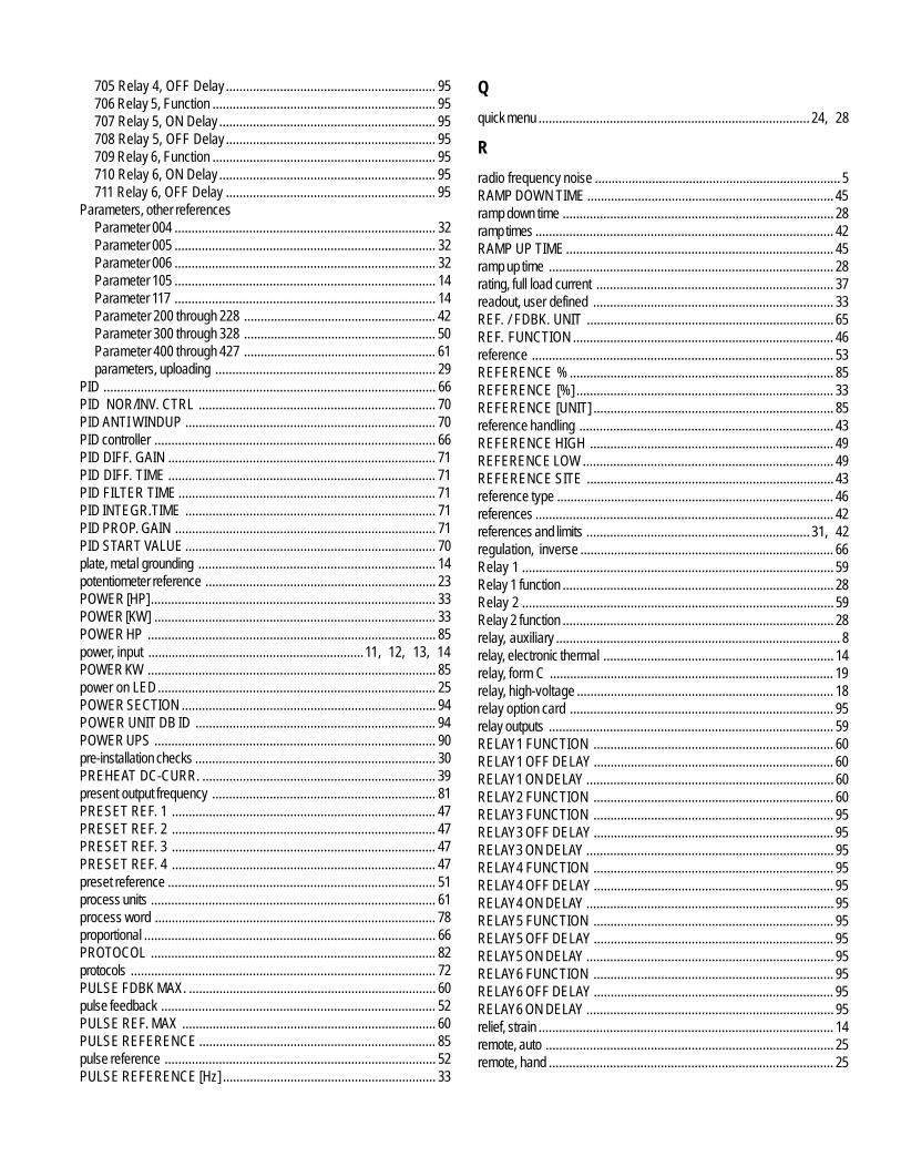
705 Relay 4, OFF Delay .............................................................. 95706 Relay 5, Function .................................................................. 95707 Relay 5, ON Delay ................................................................ 95708 Relay 5, OFF Delay .............................................................. 95709 Relay 6, Function .................................................................. 95710 Relay 6, ON Delay ................................................................ 95711 Relay 6, OFF Delay .............................................................. 95
Parameters, other referencesParameter 004 ............................................................................. 32Parameter 005 ............................................................................. 32Parameter 006 ............................................................................. 32Parameter 105 ............................................................................. 14Parameter 117 ............................................................................. 14Parameter 200 through 228 ......................................................... 42Parameter 300 through 328 ......................................................... 50Parameter 400 through 427 ......................................................... 61parameters, uploading ................................................................. 29
PID .................................................................................................. 66PID NOR/INV. CTRL ...................................................................... 70PID ANTI WINDUP .......................................................................... 70PID controller ................................................................................... 66PID DIFF. GAIN ............................................................................... 71PID DIFF. TIME ............................................................................... 71PID FILTER TIME ............................................................................ 71PID INTEGR.TIME .......................................................................... 71PID PROP. GAIN ............................................................................. 71PID START VALUE .......................................................................... 70plate, metal grounding ...................................................................... 14potentiometer reference .................................................................... 23POWER [HP] .................................................................................... 33POWER [KW] ................................................................................... 33POWER HP ..................................................................................... 85power, input ................................................................11, 12, 13, 14POWER KW ..................................................................................... 85power on LED.................................................................................. 25POWER SECTION ........................................................................... 94POWER UNIT DB ID ....................................................................... 94POWER UPS ................................................................................... 90pre-installation checks ....................................................................... 30PREHEAT DC-CURR. ..................................................................... 39present output frequency .................................................................. 81PRESET REF. 1 .............................................................................. 47PRESET REF. 2 .............................................................................. 47PRESET REF. 3 .............................................................................. 47PRESET REF. 4 .............................................................................. 47preset reference ............................................................................... 51process units .................................................................................... 61process word ................................................................................... 78proportional ...................................................................................... 66PROTOCOL .................................................................................... 82protocols .......................................................................................... 72PULSE FDBK MAX. ......................................................................... 60pulse feedback ................................................................................. 52PULSE REF. MAX ........................................................................... 60PULSE REFERENCE ...................................................................... 85pulse reference ................................................................................ 52PULSE REFERENCE [Hz] ............................................................... 33
Q
quick menu ................................................................................ 24, 28
R
radio frequency noise ......................................................................... 5RAMP DOWN TIME ......................................................................... 45ramp down time ................................................................................ 28ramp times ........................................................................................ 42RAMP UP TIME ............................................................................... 45ramp up time .................................................................................... 28rating, full load current ...................................................................... 37readout, user defined ....................................................................... 33REF. / FDBK. UNIT ......................................................................... 65REF. FUNCTION ............................................................................. 46reference ......................................................................................... 53REFERENCE % .............................................................................. 85REFERENCE [%] ............................................................................ 33REFERENCE [UNIT] ....................................................................... 85reference handling ........................................................................... 43REFERENCE HIGH ........................................................................ 49REFERENCE LOW .......................................................................... 49REFERENCE SITE ......................................................................... 43reference type .................................................................................. 46references ........................................................................................ 42references and limits .................................................................. 31, 42regulation, inverse ........................................................................... 66Relay 1 ............................................................................................ 59Relay 1 function ................................................................................ 28Relay 2 ............................................................................................ 59Relay 2 function ................................................................................ 28relay, auxiliary .................................................................................... 8relay, electronic thermal .................................................................... 14relay, form C .................................................................................... 19relay, high-voltage ............................................................................ 18relay option card .............................................................................. 95relay outputs .................................................................................... 59RELAY1 FUNCTION ....................................................................... 60RELAY1 OFF DELAY ....................................................................... 60RELAY1 ON DELAY ......................................................................... 60RELAY2 FUNCTION ....................................................................... 60RELAY3 FUNCTION ....................................................................... 95RELAY3 OFF DELAY ....................................................................... 95RELAY3 ON DELAY ......................................................................... 95RELAY4 FUNCTION ....................................................................... 95RELAY4 OFF DELAY ....................................................................... 95RELAY4 ON DELAY ......................................................................... 95RELAY5 FUNCTION ....................................................................... 95RELAY5 OFF DELAY ....................................................................... 95RELAY5 ON DELAY ......................................................................... 95RELAY6 FUNCTION ....................................................................... 95RELAY6 OFF DELAY ....................................................................... 95RELAY6 ON DELAY ......................................................................... 95relief, strain ....................................................................................... 14remote, auto ..................................................................................... 25remote, hand .................................................................................... 25
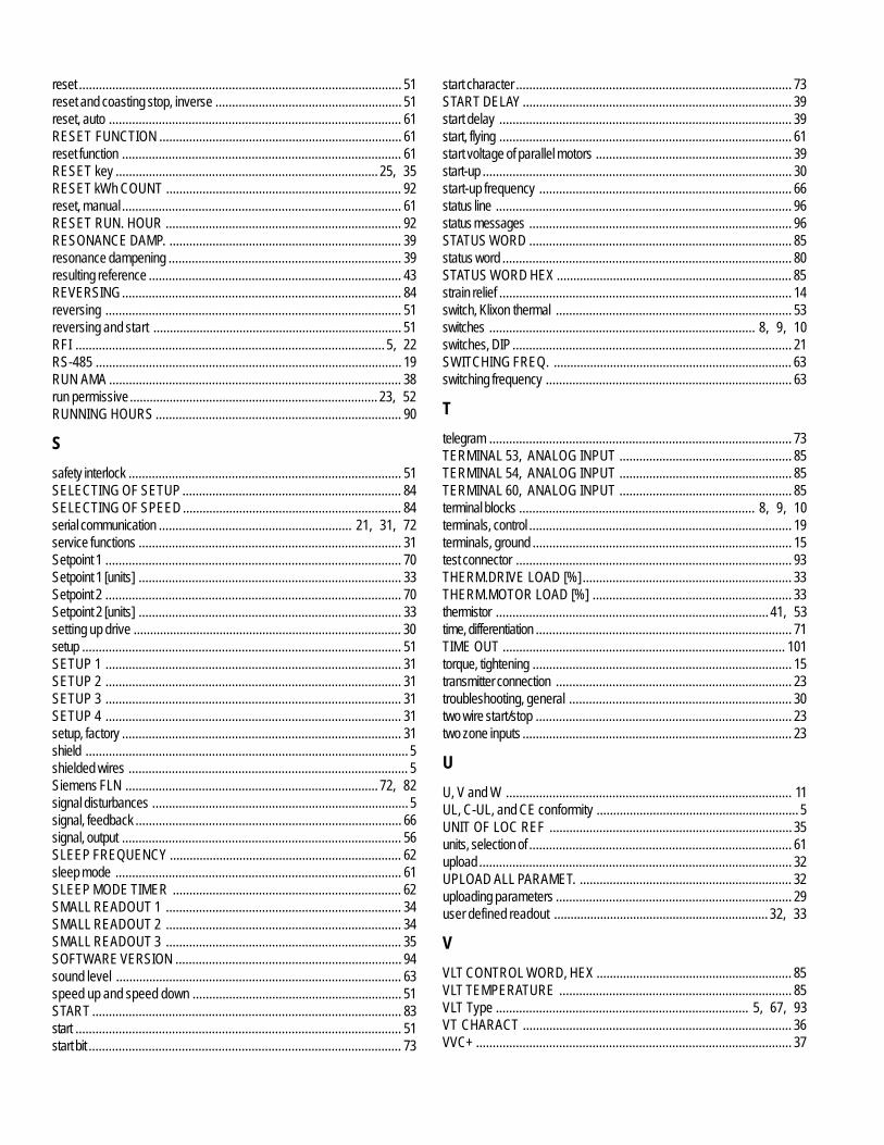
reset ................................................................................................. 51reset and coasting stop, inverse ........................................................ 51reset, auto ........................................................................................ 61RESET FUNCTION ......................................................................... 61reset function .................................................................................... 61RESET key ............................................................................... 25, 35RESET kWh COUNT ....................................................................... 92reset, manual .................................................................................... 61RESET RUN. HOUR ....................................................................... 92RESONANCE DAMP. ...................................................................... 39resonance dampening ...................................................................... 39resulting reference ............................................................................ 43REVERSING.................................................................................... 84reversing ......................................................................................... 51reversing and start ........................................................................... 51RFI ............................................................................................. 5, 22RS-485 ............................................................................................ 19RUN AMA ........................................................................................ 38run permissive ........................................................................... 23, 52RUNNING HOURS .......................................................................... 90
S
safety interlock .................................................................................. 51SELECTING OF SETUP .................................................................. 84SELECTING OF SPEED .................................................................. 84serial communication .......................................................... 21, 31, 72service functions ............................................................................... 31Setpoint 1 ......................................................................................... 70Setpoint 1 [units] ............................................................................... 33Setpoint 2 ......................................................................................... 70Setpoint 2 [units] ............................................................................... 33setting up drive ................................................................................. 30setup ................................................................................................ 51SETUP 1 ......................................................................................... 31SETUP 2 ......................................................................................... 31SETUP 3 ......................................................................................... 31SETUP 4 ......................................................................................... 31setup, factory .................................................................................... 31shield ................................................................................................. 5shielded wires .................................................................................... 5Siemens FLN ............................................................................ 72, 82signal disturbances ............................................................................. 5signal, feedback ................................................................................ 66signal, output .................................................................................... 56SLEEP FREQUENCY ...................................................................... 62sleep mode ...................................................................................... 61SLEEP MODE TIMER ..................................................................... 62SMALL READOUT 1 ....................................................................... 34SMALL READOUT 2 ....................................................................... 34SMALL READOUT 3 ....................................................................... 35SOFTWARE VERSION .................................................................... 94sound level ...................................................................................... 63speed up and speed down ............................................................... 51START ............................................................................................. 83start .................................................................................................. 51start bit .............................................................................................. 73
start character ................................................................................... 73START DELAY ................................................................................. 39start delay ........................................................................................ 39start, flying ........................................................................................ 61start voltage of parallel motors ........................................................... 39start-up ............................................................................................. 30start-up frequency ............................................................................ 66status line ......................................................................................... 96status messages ............................................................................... 96STATUS WORD ............................................................................... 85status word ....................................................................................... 80STATUS WORD HEX ....................................................................... 85strain relief ........................................................................................ 14switch, Klixon thermal ....................................................................... 53switches ................................................................................ 8, 9, 10switches, DIP.................................................................................... 21SWITCHING FREQ. ........................................................................ 63switching frequency .......................................................................... 63
T
telegram ........................................................................................... 73TERMINAL 53, ANALOG INPUT .................................................... 85TERMINAL 54, ANALOG INPUT .................................................... 85TERMINAL 60, ANALOG INPUT .................................................... 85terminal blocks ....................................................................... 8, 9, 10terminals, control ............................................................................... 19terminals, ground .............................................................................. 15test connector ................................................................................... 93THERM.DRIVE LOAD [%] ............................................................... 33THERM.MOTOR LOAD [%] ............................................................ 33thermistor .................................................................................. 41, 53time, differentiation ............................................................................. 71TIME OUT ..................................................................................... 101torque, tightening .............................................................................. 15transmitter connection ....................................................................... 23troubleshooting, general ................................................................... 30two wire start/stop ............................................................................. 23two zone inputs ................................................................................. 23
U
U, V and W ...................................................................................... 11UL, C-UL, and CE conformity ............................................................. 5UNIT OF LOC REF ......................................................................... 35units, selection of ............................................................................... 61upload .............................................................................................. 32UPLOAD ALL PARAMET. ................................................................ 32uploading parameters ....................................................................... 29user defined readout ................................................................. 32, 33
V
VLT CONTROL WORD, HEX ........................................................... 85VLT TEMPERATURE ...................................................................... 85VLT Type ............................................................................ 5, 67, 93VT CHARACT ................................................................................. 36VVC+ ............................................................................................... 37
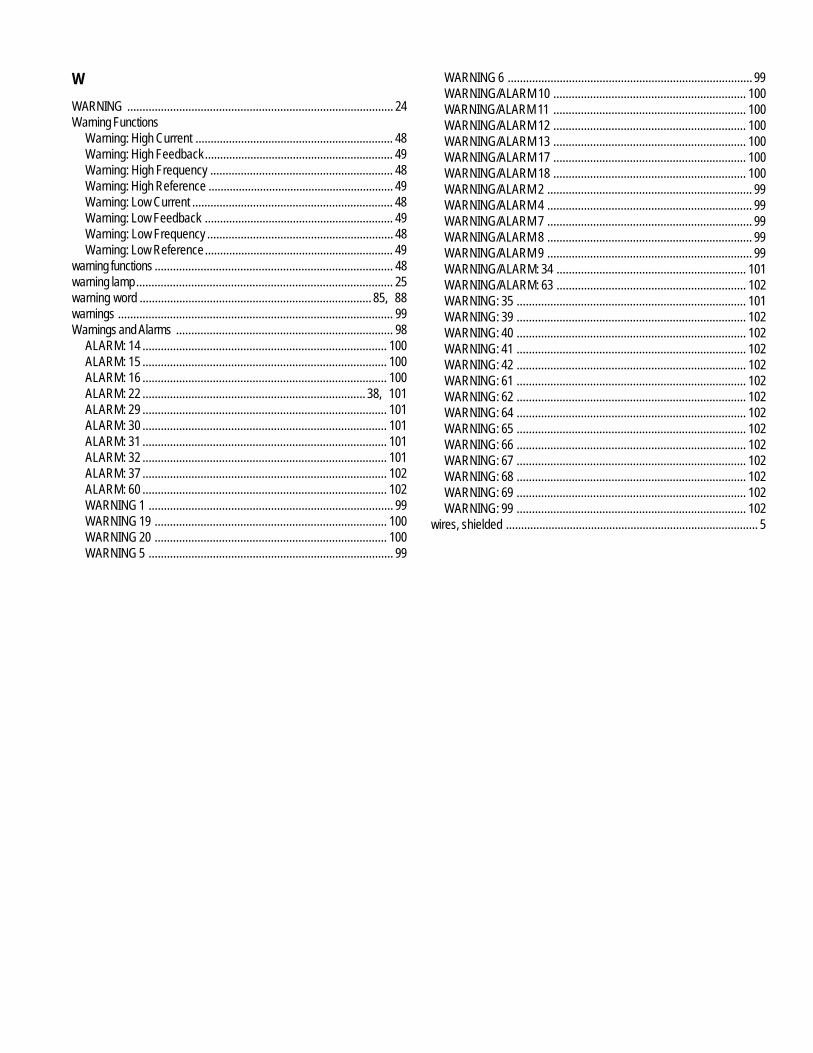
W
WARNING ....................................................................................... 24Warning Functions
Warning: High Current ................................................................. 48Warning: High Feedback.............................................................. 49Warning: High Frequency ............................................................ 48Warning: High Reference ............................................................. 49Warning: Low Current .................................................................. 48Warning: Low Feedback .............................................................. 49Warning: Low Frequency ............................................................. 48Warning: Low Reference.............................................................. 49
warning functions .............................................................................. 48warning lamp.................................................................................... 25warning word ............................................................................ 85, 88warnings .......................................................................................... 99Warnings and Alarms ....................................................................... 98
ALARM: 14 ................................................................................ 100ALARM: 15 ................................................................................ 100ALARM: 16 ................................................................................ 100ALARM: 22 ......................................................................... 38, 101ALARM: 29 ................................................................................ 101ALARM: 30 ................................................................................ 101ALARM: 31 ................................................................................ 101ALARM: 32 ................................................................................ 101ALARM: 37 ................................................................................ 102ALARM: 60 ................................................................................ 102WARNING 1 ................................................................................ 99WARNING 19 ............................................................................ 100WARNING 20 ............................................................................ 100WARNING 5 ................................................................................ 99
WARNING 6 ................................................................................ 99WARNING/ALARM 10 ............................................................... 100WARNING/ALARM 11 ............................................................... 100WARNING/ALARM 12 ............................................................... 100WARNING/ALARM 13 ............................................................... 100WARNING/ALARM 17 ............................................................... 100WARNING/ALARM 18 ............................................................... 100WARNING/ALARM 2 ................................................................... 99WARNING/ALARM 4 ................................................................... 99WARNING/ALARM 7 ................................................................... 99WARNING/ALARM 8 ................................................................... 99WARNING/ALARM 9 ................................................................... 99WARNING/ALARM: 34 .............................................................. 101WARNING/ALARM: 63 .............................................................. 102WARNING: 35 ........................................................................... 101WARNING: 39 ........................................................................... 102WARNING: 40 ........................................................................... 102WARNING: 41 ........................................................................... 102WARNING: 42 ........................................................................... 102WARNING: 61 ........................................................................... 102WARNING: 62 ........................................................................... 102WARNING: 64 ........................................................................... 102WARNING: 65 ........................................................................... 102WARNING: 66 ........................................................................... 102WARNING: 67 ........................................................................... 102WARNING: 68 ........................................................................... 102WARNING: 69 ........................................................................... 102WARNING: 99 ........................................................................... 102
wires, shielded ................................................................................... 5

118 VLT is a registered Danfoss trademark
NOTES