Embed Size (px)
Citation preview
DC MotorsMoteurs à courant continuGleichstrommotoren
DMP catalogue1-170 kW, 5-1000 Nm
1
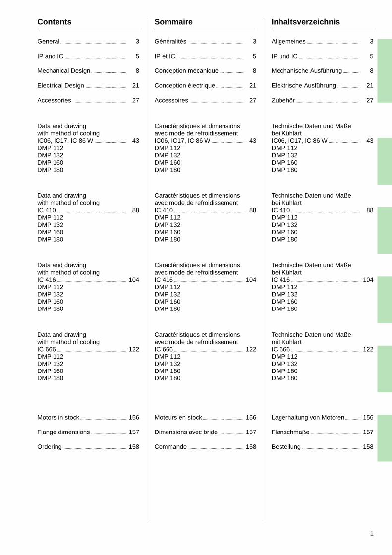
Contents
General ............................................................ 3
IP and IC ........................................................ 5
Mechanical Design ................................ 8
Electrical Design ..................................... 21
Accessories ................................................. 27
Data and drawingwith method of coolingIC06, IC17, IC 86 W ............................. 43DMP 112DMP 132DMP 160DMP 180
Data and drawingwith method of coolingIC 410 ............................................................... 88DMP 112DMP 132DMP 160DMP 180
Data and drawingwith method of coolingIC 416 ............................................................... 104DMP 112DMP 132DMP 160DMP 180
Data and drawingwith method of coolingIC 666 ............................................................... 122DMP 112DMP 132DMP 160DMP 180
Motors in stock .......................................... 156
Flange dimensions ................................ 157
Ordering .......................................................... 158
Sommaire
Généralités ................................................... 3
IP et IC ............................................................. 5
Conception mécanique ...................... 8
Conception électrique ......................... 21
Accessoires ................................................. 27
Caractéristiques et dimensionsavec mode de refroidissementIC06, IC17, IC 86 W ............................. 43DMP 112DMP 132DMP 160DMP 180
Caractéristiques et dimensionsavec mode de refroidissementIC 410 ............................................................... 88DMP 112DMP 132DMP 160DMP 180
Caractéristiques et dimensionsavec mode de refroidissementIC 416 ............................................................... 104DMP 112DMP 132DMP 160DMP 180
Caractéristiques et dimensionsavec mode de refroidissementIC 666 ............................................................... 122DMP 112DMP 132DMP 160DMP 180
Moteurs en stock ..................................... 156
Dimensions avec bride ...................... 157
Commande .................................................. 158
Inhaltsverzeichnis
Allgemeines ................................................. 3
IP und IC ........................................................ 5
Mechanische Ausführung ................ 8
Elektrische Ausführung ..................... 21
Zubehör ........................................................... 27
Technische Daten und Maßebei KühlartIC06, IC17, IC 86 W ............................. 43DMP 112DMP 132DMP 160DMP 180
Technische Daten und Maßebei KühlartIC 410 ............................................................... 88DMP 112DMP 132DMP 160DMP 180
Technische Daten und Maßebei KühlartIC 416 ............................................................... 104DMP 112DMP 132DMP 160DMP 180
Technische Daten und Maßemit KühlartIC 666 ............................................................... 122DMP 112DMP 132DMP 160DMP 180
Lagerhaltung von Motoren .............. 156
Flanschmaße ............................................. 157
Bestellung .................................................... 158

3
General
Catalogue validityInformation given in this catalogue issubject to modification in the interestof technical progress without furthernotice.
Motor/Generator optionThe machines are designed asvariable speed motors, but can alsobe used as generators. Thecorresponding data can be suppliedon request.
Direction of rotationThe motors listed in this catalogueare suitable for rotation in eitherdirection. However, to achieveoptimum performance see alsochapter “Brush gear” p 11.
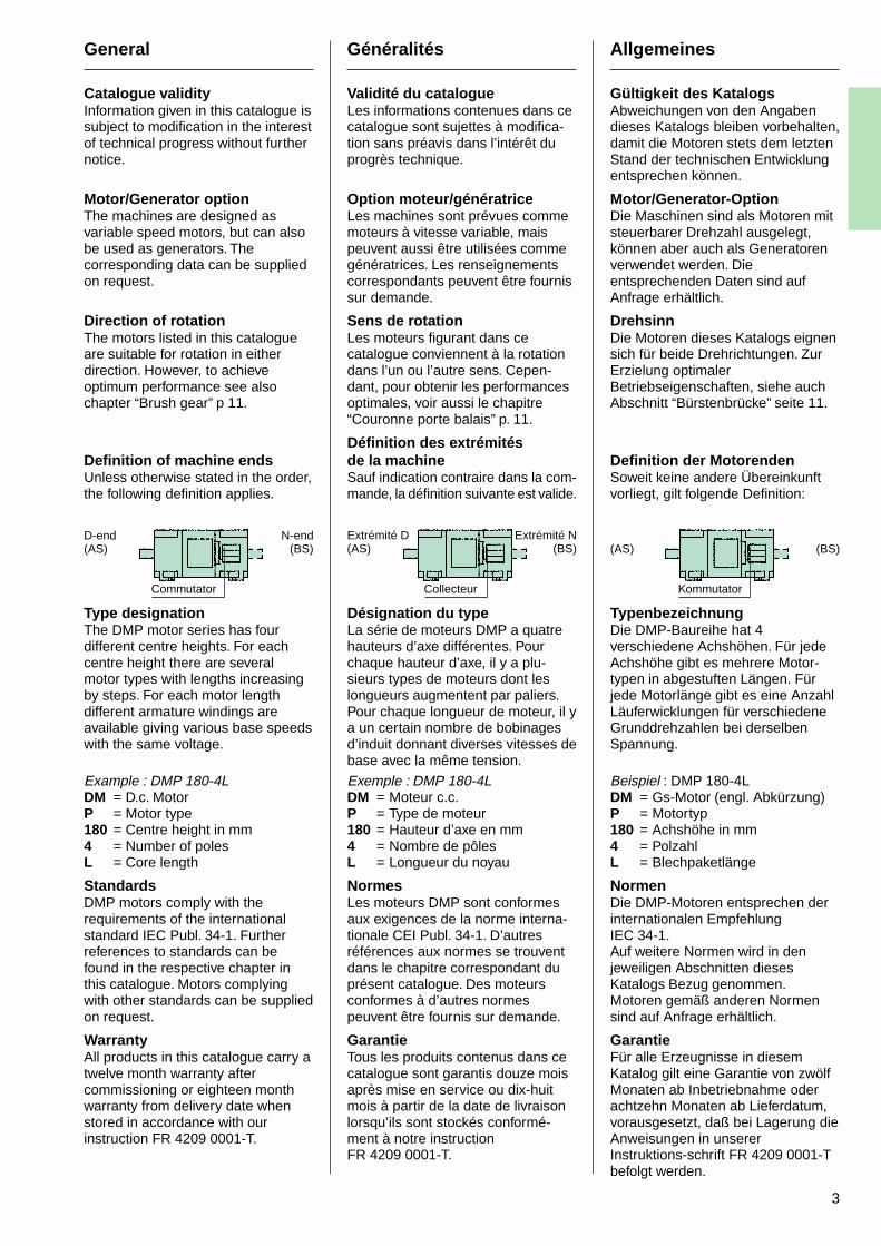
Definition of machine endsUnless otherwise stated in the order,the following definition applies.
Type designationThe DMP motor series has fourdifferent centre heights. For eachcentre height there are severalmotor types with lengths increasingby steps. For each motor lengthdifferent armature windings areavailable giving various base speedswith the same voltage.
Example : DMP 180-4LDM = D.c. MotorP = Motor type180 = Centre height in mm4 = Number of polesL = Core length
StandardsDMP motors comply with therequirements of the internationalstandard IEC Publ. 34-1. Furtherreferences to standards can befound in the respective chapter inthis catalogue. Motors complyingwith other standards can be suppliedon request.
WarrantyAll products in this catalogue carry atwelve month warranty aftercommissioning or eighteen monthwarranty from delivery date whenstored in accordance with ourinstruction FR 4209 0001-T.
Généralités
Validité du catalogueLes informations contenues dans cecatalogue sont sujettes à modifica-tion sans préavis dans l’intérêt duprogrès technique.
Option moteur/génératriceLes machines sont prévues commemoteurs à vitesse variable, maispeuvent aussi être utilisées commegénératrices. Les renseignementscorrespondants peuvent être fournissur demande.
Sens de rotationLes moteurs figurant dans cecatalogue conviennent à la rotationdans l’un ou l’autre sens. Cepen-dant, pour obtenir les performancesoptimales, voir aussi le chapitre“Couronne porte balais” p. 11.
Définition des extrémitésde la machineSauf indication contraire dans la com-mande, la définition suivante est valide.
Désignation du typeLa série de moteurs DMP a quatrehauteurs d’axe différentes. Pourchaque hauteur d’axe, il y a plu-sieurs types de moteurs dont leslongueurs augmentent par paliers.Pour chaque longueur de moteur, il ya un certain nombre de bobinagesd’induit donnant diverses vitesses debase avec la même tension.
Exemple : DMP 180-4LDM = Moteur c.c.P = Type de moteur180 = Hauteur d’axe en mm4 = Nombre de pôlesL = Longueur du noyau
NormesLes moteurs DMP sont conformesaux exigences de la norme interna-tionale CEI Publ. 34-1. D’autresréférences aux normes se trouventdans le chapitre correspondant duprésent catalogue. Des moteursconformes à d’autres normespeuvent être fournis sur demande.
GarantieTous les produits contenus dans cecatalogue sont garantis douze moisaprès mise en service ou dix-huitmois à partir de la date de livraisonlorsqu’ils sont stockés conformé-ment à notre instructionFR 4209 0001-T.
Allgemeines
Gültigkeit des KatalogsAbweichungen von den Angabendieses Katalogs bleiben vorbehalten,damit die Motoren stets dem letztenStand der technischen Entwicklungentsprechen können.
Motor/Generator-OptionDie Maschinen sind als Motoren mitsteuerbarer Drehzahl ausgelegt,können aber auch als Generatorenverwendet werden. Dieentsprechenden Daten sind aufAnfrage erhältlich.
DrehsinnDie Motoren dieses Katalogs eignensich für beide Drehrichtungen. ZurErzielung optimalerBetriebseigenschaften, siehe auchAbschnitt “Bürstenbrücke” seite 11.
Definition der MotorendenSoweit keine andere Übereinkunftvorliegt, gilt folgende Definition:
TypenbezeichnungDie DMP-Baureihe hat 4verschiedene Achshöhen. Für jedeAchshöhe gibt es mehrere Motor-typen in abgestuften Längen. Fürjede Motorlänge gibt es eine AnzahlLäuferwicklungen für verschiedeneGrunddrehzahlen bei derselbenSpannung.
Beispiel : DMP 180-4LDM = Gs-Motor (engl. Abkürzung)P = Motortyp180 = Achshöhe in mm4 = PolzahlL = Blechpaketlänge
NormenDie DMP-Motoren entsprechen derinternationalen EmpfehlungIEC 34-1.Auf weitere Normen wird in denjeweiligen Abschnitten diesesKatalogs Bezug genommen.Motoren gemäß anderen Normensind auf Anfrage erhältlich.
GarantieFür alle Erzeugnisse in diesemKatalog gilt eine Garantie von zwölfMonaten ab Inbetriebnahme oderachtzehn Monaten ab Lieferdatum,vorausgesetzt, daß bei Lagerung dieAnweisungen in unsererInstruktions-schrift FR 4209 0001-Tbefolgt werden.
D-end(AS)
N-end(BS)
Commutator
(AS) (BS)
Kommutator
Extrémité D(AS)
Extrémité N(BS)
Collecteur
4
General
UnitsComma signs (,) are used through-out the tables to indicate decimals.Conversion factors are given belowin order to facilitate calculations.
1 kg = 2,20 lb1 kgm2 = 23,73 lb ft2
1 kW = 1,34 HP1 Nm = 0,7375 lbf. ft1 m3/s = 35,31 cu. ft/s1m3/h = 0,59 cu ft/min (CFM)1 Pa = 1 N/m2 = 0,1 mm H2O
= 1,45 x 10⁻⁴ lbf/sq.in (PSI)1 atm = 1,0 x 10⁵ Pa
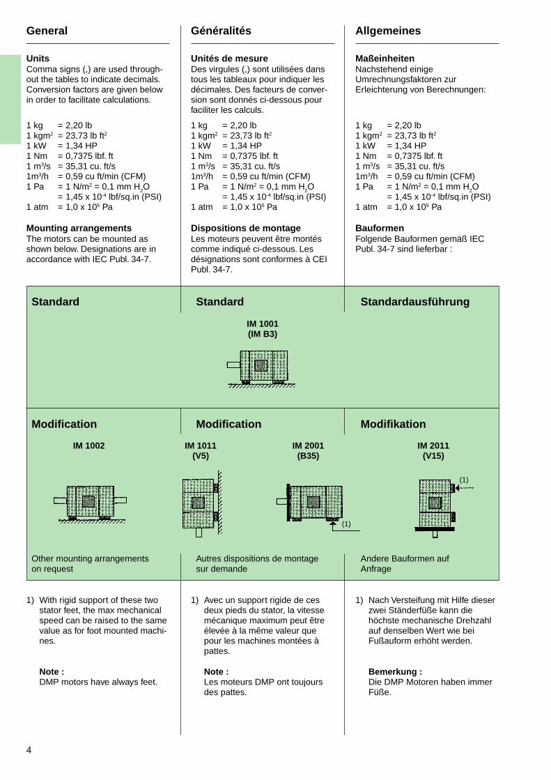
Mounting arrangementsThe motors can be mounted asshown below. Designations are inaccordance with IEC Publ. 34-7.
Standard
Modification
Other mounting arrangementson request
1) With rigid support of these twostator feet, the max mechanicalspeed can be raised to the samevalue as for foot mounted machi-nes.
Note :DMP motors have always feet.
Généralités
Unités de mesureDes virgules (,) sont utilisées danstous les tableaux pour indiquer lesdécimales. Des facteurs de conver-sion sont donnés ci-dessous pourfaciliter les calculs.
1 kg = 2,20 lb1 kgm2 = 23,73 lb ft2
1 kW = 1,34 HP1 Nm = 0,7375 lbf. ft1 m3/s = 35,31 cu. ft/s1m3/h = 0,59 cu ft/min (CFM)1 Pa = 1 N/m2 = 0,1 mm H2O
= 1,45 x 10⁻⁴ lbf/sq.in (PSI)1 atm = 1,0 x 10⁵ Pa
Dispositions de montageLes moteurs peuvent être montéscomme indiqué ci-dessous. Lesdésignations sont conformes à CEIPubl. 34-7.
Standard
IM 1001(IM B3)
Modification
Autres dispositions de montagesur demande
1) Avec un support rigide de cesdeux pieds du stator, la vitessemécanique maximum peut êtreélevée à la même valeur quepour les machines montées àpattes.
Note :Les moteurs DMP ont toujoursdes pattes.
Allgemeines
MaßeinheitenNachstehend einigeUmrechnungsfaktoren zurErleichterung von Berechnungen:
1 kg = 2,20 lb1 kgm2 = 23,73 lb ft2
1 kW = 1,34 HP1 Nm = 0,7375 lbf. ft1 m3/s = 35,31 cu. ft/s1m3/h = 0,59 cu ft/min (CFM)1 Pa = 1 N/m2 = 0,1 mm H2O
= 1,45 x 10⁻⁴ lbf/sq.in (PSI)1 atm = 1,0 x 10⁵ Pa
BauformenFolgende Bauformen gemäß IECPubl. 34-7 sind lieferbar :
Standardausführung
Modifikation
Andere Bauformen aufAnfrage
1) Nach Versteifung mit Hilfe dieserzwei Ständerfüße kann diehöchste mechanische Drehzahlauf denselben Wert wie beiFußauform erhöht werden.
Bemerkung :Die DMP Motoren haben immerFüße.
(1)
(1)
IM 1002 IM 1011(V5)
IM 2001(B35)
IM 2011(V15)
5
IP and IC
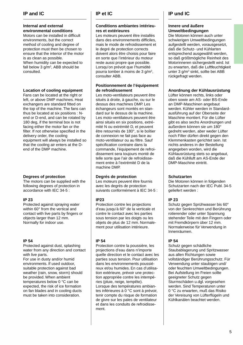
Internal and externalenvironmental conditionsMotors can be installed in difficultenvironments, but the correctmethod of cooling and degree ofprotection must then be chosen toensure that the interior of the motoris as clean as possible.When humidity can be expected tofall below 3 g/m3, ABB should beconsulted.
Location of cooling equipmentFans can be located at the right orleft, or above DMP machines. Heatexchangers are standard fitted onthe top of the machine. The fans canthus be located at six positions : N-end or D-end, and can be rotated by180 deg, if the terminal box is notfacing either the motor fan or thefilter. If not otherwise specified in thedelivery order, the coolingequipment will always be installed sothat the cooling air enters at the D-end of the DMP machine.
Degrees of protectionThe motors can be supplied with thefollowing degrees of protection inaccordance with IEC 34-5 :
IP 23Protected against spraying waterwithin 60° from the vertical andcontact with live parts by fingers orobjects larger than 12 mm.Normally for indoor use.
IP 54Protected against dust, splashingwater from any direction and contactwith live parts.For use in dusty and/or humidenvironments. If used outdoor,suitable protection against badweather (rain, snow, storm) shouldbe provided. When ambienttemperatures below 0 °C can beexpected, the risk of ice formationon fan blades and in cooling ductsmust be taken into consideration.
IP et IC
Conditions ambiantes intérieu-res et extérieuresLes moteurs peuvent être installésdans des environnements difficiles,mais le mode de refroidissement etle degré de protection correctsdoivent alors être choisis pour faireen sorte que l’intérieur du moteurreste aussi propre que possible.Lorsqu’on prévoit que l’humiditépourra tomber à moins de 3 g/m3,consulter ABB.
Positionnement de l’équipementde refroidissementLes moto-ventilateurs peuvent êtresitués à droite, à gauche, ou sur ledessus des machines DMP. Leséchangeurs sont montés en stan-dard sur le dessus de la machine.Les moto-ventilateurs peuvent êtreainsi situés en six positions, extré-mité N ou extrémité D, et peuventêtre retournés de 180°, si le boîtierde connexion ne fait pas face aumoto-ventilateur ou au filtre. Saufspécification contraire dans lacommande, l’équipement de refroi-dissement sera toujours monté detelle sorte que l’air de refroidisse-ment entre à l’extrémité D de lamachine DMP.
Degrés de protectionLes moteurs peuvent être fournisavec les degrés de protectionsuivants conformément à IEC 34-5 :
IP23Protection contre les projectionsd’eau jusqu’à 60° de la verticale etcontre le contact avec les partiessous tension par les doigts ou lesobjets de plus de 12 mm. Normale-ment pour utilisation intérieure.
IP 54Protection contre la poussière, lesprojections d’eau dans n’importequelle direction et le contact avec lesparties sous tension. Pour utilisationdans les environnements poussié-reux et/ou humides. En cas d’utilisa-tion extérieure, prévoir une protec-tion appropriée contre les intempé-ries (pluie, neige, tempête).Lorsque des températures ambian-tes inférieures à 0 °C sont à prévoir,tenir compte du risque de formationde givre sur les pales de ventilateuret dans les conduits de refroidisse-ment.
IP und IC
Innere und äußereUmweltbedingungenDie Motoren können auch unterschwierigen Umweltbedingungenaufgestellt werden, vorausgesetzt,daß die Schutz- und Kühlartenentsprechend ausgewählt werden,so daß größtmögliche Reinheit desMotorinneren sichergestellt wird. Istzu erwarten, daß die Luftfeuchtigkeitunter 3 g/m3 sinkt, sollte bei ABBrückgefragt werden.
Anordnung der KühlausrüstungLüfter können rechts, links oderoben sowie am AS- oder BS-Endean DMP-Maschinen angebautwerden. Kühler werden in Standard-ausführung auf der Oberseite derMaschine montiert. Für die Lüftergibt es also sechs Anordnungen undaußerdem können sie um 180°gedreht werden, aber weder Lüfternoch Filter dürfen direkt gegen denKlemmenkasten gerichtet sein. Istnichts anderes in der Bestellungangegeben worden, wird dieKühlausrüstung stets so angebaut,daß die Kühlluft am AS-Ende derDMP-Maschine eintritt.
SchutzartenDie Motoren können in folgendenSchutzarten nach der IEC Publ. 34-5geliefert werden :
IP 23Schutz gegen Sprühwasser bis 60°von der Senkrechten und Berührungrotierender oder unter Spannungstehender Teile mit den Fingern odermit Fremdkörpern über 12 mm.Normalerweise für Verwendung inInnenräumen.
IP 54Schutz gegen schädlicheStaubablagerung und Spritzwasseraus allen Richtungen sowievollständiger Berührungsschutz. FürVerwendung unter staubigen und/oder feuchten Umweltbedingungen.Bei Aufstellung im Freien solltegeeigneter Schutz gegenSturmschäden u.dgl. vorgesehenwerden. Sind Temperaturen unter0 °C zu erwarten, muß das Risikoder Vereisung von Lüfterflügeln undKühlkanälen beachtet werden.
6
IP and IC
IP 55Protected against dust, jets of waterfrom any direction and contact withlive parts. For use in exposedlocations, outdoor or indoor. Wheretropical storms occur, the machineshould be enclosed within screenwalls and a roof to provide protectionagainst flying debris. When ambienttemperatures below 0 °C can beexpected, the risk of ice formationon fan blades and in cooling ductsmust be taken into consideration.
Methods of coolingThe cooling forms comply with IECPubl. 34-6. The recommendedmethod of cooling is determined bythe environment and the location ofthe motor. The cooling form selectedshould supply cooling air for d.c.motors at temperatures between –5and + 40 °C. Motors for operation atother temperatures can be suppliedon request. Standard DMP-machi-nes have the cooling air intake at theD-end. Modified versions with the airintake at the N-end (commutatorend) can be supplied. Cooling airinlet from below is available as amodification at extra cost for use inaggressive atmospheres containingchlorine, sulphur, potassium etc. Aclosed cooling system in which thed.c. motor is cooled with air at over-pressure from a clean source isrecommended. For machines withheat exchangers, the pick-up airfilter is replaced with a connection tothe clean air supply. The agressiveenvironmental air should also beprevented from entering the motorduring non-operational periods.
IP et IC
IP55Protection contre la poussière, lesjets d’eau dans n’importe quelledirection et le contact avec lesparties sous tension. Pour utilisationdans les emplacements exposés, àl’extérieur ou à l’intérieur. En cas detempête tropicale, la machine doitêtre enfermée dans une enceintegrillagée munie d’un toit pourassurer la protection contre lesdébris volants. Lorsque des tempé-ratures ambiantes inférieures à 0 °Csont à prévoir, tenir compte durisque de formation de givre sur lespales de ventilateur et dans lesconduits de refroidissement.
Mode de refroidissementLes modes de refroidissement sontconformes à CEI Publ. 34-6. Lemode de refroidissement recom-mandé est déterminé par l’environ-nement et l’emplacement du moteur.Le mode de refroidissement choisidoit fournir de l’air de refroidisse-ment pour les moteurs c.c. à destempératures comprises entre –5 et+40 °C. Des moteurs pouvantfonctionner à d’autres températurespeuvent être fournis sur demande.Les machines DMP standard ont laprise d’air de refroidissement àl’extrémité D. Des versions modifiéesayant la prise d’air à l’extrémité N(côté collecteur) peuvent êtrefournies. L’entrée d’air de refroidisse-ment par-dessous est disponiblecomme modification à utiliser dansles atmosphères corrosives conte-nant du chlore, du soufre, du potas-sium, etc. Un système de refroidis-sement fermé dans lequel le moteurc.c. est refroidi par de l’air pressuriséprovenant d’une source propre estrecommandé. Pour les machines àéchangeurs de chaleur, le filtre deprise d’air est remplacé par unraccord à la source d’air propre. Ilfaut également empêcher l’air dumilieu corrosif de pénétrer dans lemoteur pendant les périodes derepos.
IP und IC
IP 55Schutz gegen schädlicheStaubablagerung und Strahlwasseraus allen Richtungen sowievollständiger Berührungsschutz. FürVerwendung in ausgesetztenBereichen in Innenräumen oder imFreien. Wo tropische Stürmevorkommen, sind Abschirmungenund Überdachungen zum Schutzgegen fliegende Bruchstückevorzusehen. Sind Temperaturenunter 0 °C zu erwarten, muß dasRisiko der Vereisung vonLüfterflügeln und Kühlkanälenbeachtet werden.
KühlartenDie Kühlarten entsprechen der IECPubl. 34-6. Bei der Wahl der Kühlartmüssen dieUmgebungsbedingungen amAufstellungsort der Maschineberücksichtigt werden. Bei dergewählten Kühlart soll die Kühllufteine Temperatur zwischen – 5 und +40 °C halten. Motoren für Betrieb beianderen Temperaturen sind aufAnfrage erhältlich.In Standardausführung haben dieDMP-Maschinen die Kühlluft-Eintrittsöffnung am AS-Ende.Modifizierte Ausführungen mitLufteintritt am BS-Ende(Kommutator-ende) sind lieferbar.Als Modifikation ist auchKühllufteintritt vonunten gegenMehrpreis erhältlich. FürVerwendung in aggresiver, z.B.chlor-, schwefel- oder kohlenoxid-haltiger Atmosphäre empfiehlt sichein geschlossenes Kühlsystem, indem die Maschine unter Überdruckmit reiner Luft von außerhalb gekühltwird. Ein Eindringen der aggressivenUmgebungsluft in die Maschinesollte auch währendStillstandsperioden verhindertwerden.
7
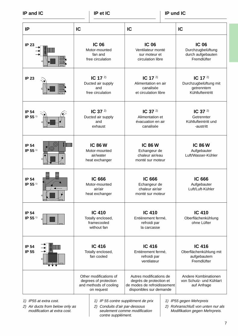
IP and IC IP et IC IP und IC
IP IC IC IC
IP 23 IC 06 IC 06 IC 06Motor-mounted Ventilateur monté Durchzugbelüftung
fan and sur moteur et durch aufgebautenfree circulation circulation libre Fremdlüfter
IP 23 IC 17 2) IC 17 2) IC 17 2)
Ducted air supply Alimentation en air Durchzugbelüftung mitand canalisée getrenntem
free circulation et circulation libre Kühllufteintritt
IP 54 IC 37 2) IC 37 2) IC 37 2)
IP 55 1) Ducted air supply Alimentation et Getrennterand évacuation en air Kühllufteintritt und
exhaust canalisée -austritt
IP 54 IC 86 W IC 86 W IC 86 WIP 55 1) Motor-mounted Echangeur de Aufgebauter
air/water chaleur air/eau Luft/Wasser-Kühlerheat exchanger monté sur moteur
IP 54 IC 666 IC 666 IC 666IP 55 1) Motor-mounted Echangeur de Aufgebauter
air/air chaleur air/air Luft/Luft-Kühlerheat exchanger monté sur moteur
IP 54 IC 410 IC 410 IC 410IP 55 1) Totally enclosed, Entièrement fermé, Oberflächenkühlung
framecooled refroidi par ohne Lüfterwithout fan la carcasse
IP 54 IC 416 IC 416 IC 416IP 55 Totally enclosed, Entièrement fermé, Oberflächenkühlung mit
fan cooled refroidi par aufgebautemventilateur Fremdlüfter
Other modifications of Autres modifications de Andere Kombinationendegrees of protection degrés de protection et von Schutz- und Kühlart
and methods of cooling de modes de refroidissement auf Anfrageon request disponibles sur demande
1) IP55 at extra cost.2) Air ducts from below only as
modification at extra cost.
1) IP 55 contre supplément de prix2) Conduits d’air par-dessous
seulement comme modificationcontre supplément.
1) IP55 gegen Mehrpreis2) Rohranschluß von unten nur als
Modifikation gegen Mehrpreis.
8
Mechanical Design
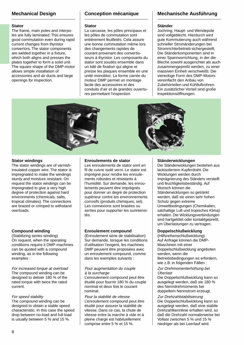
StatorThe frame, main poles and interpo-les are fully laminated. This ensuresgood commutation even during rapidcurrent changes from thyristorconvertors. The stator componentsare welded together in a fixture,which both aligns and presses theplates together to form a solid unit.The square shape of the DMP-motorallows simple installation ofaccessories and air ducts and largeopenings for inspection.
Stator windingsThe stator windings are of varnish-insulated copper wire. The stator isimpregnated to make the windingssturdy and moisture resistant. Onrequest the stator windings can beimpregnated to give a very highdegree of protection against hardenvironments (chemicals, salts,tropical climates). The connectionsare brazed or crimped to withstandoverloads.
Compound winding(Stabilizing series winding)On request, when the operatingconditions require it DMP-machinescan be quoted with a compoundwinding, as in the followingexamples :
For increased torque at overloadThe compound winding can bedesigned to deliver 180 % of therated torque with twice the ratedcurrent.
For speed stabilityThe compound winding can bedesigned to obtain a stable speedcharacteristic. In this case the speeddrop between no-load and full-loadis usually between 5 % and 15 %.
Conception mécanique
StatorLa carcasse, les pôles principaux etles pôles de commutation sontentièrement feuilletés. Cela assureune bonne commutation même lorsdes changements rapides decourant provenant des convertis-seurs à thyristor. Les composants dustator sont soudés ensemble dansun bâti de fixation qui aligne etpresse les plaques ensemble en uneunité monobloc. La forme carrée dumoteur DMP permet un montagefacile des accessoires et desconduits d’air et de grandes ouvertu-res permettant l’inspection.
Enroulements de statorLes enroulements de stator sont enfil de cuivre isolé verni. Le stator estimprégné pour rendre les enroule-ments robustes et résistants àl’humidité. Sur demande, les enrou-lements peuvent être imprégnéspour donner un degré de protectionsupérieur contre les environnementscorrosifs (produits chimiques, sel).Les connexions sont brasées ouserties pour supporter les surintensi-tés.
Enroulement compound(Enroulement série de stabilisation)Sur demande, lorsque les conditionsd’utilisation l’exigent, les machinesDMP peuvent être proposées avecun enroulement compound, commedans les exemples suivants :
Pour augmentation du coupleà la surchargeL’enroulement compound peut êtreétudié pour fournir 180 % du couplenominal et deux fois le courantnominal.
Pour la stabilité de vitesseL’enroulement compound peut êtreétudié pour assurer la stabilité devitesse. Dans ce cas, la chute devitesse entre la marche à vide et àpleine charge est habituellementcomprise entre 5 % et 15 %.
Mechanische Ausführung
StänderJochring, Haupt- und Wendepolesind vollgeblecht. Hierdurch wirdgute Kommutierung auch währendschneller Stromänderungen beiStromrichterbetrieb sichergestellt.Die Ständerkomponenten sind ineiner Spannvorrichtung, in der dieBleche sowohl ausgerichtet als auchzusammengepreßt werden, zu einermassiven Einheit verschweißt. Dieviereckige Form des DMP-Motorsvereinfacht den Anbau vonZubehörteilen und Kühlluftrohren.Ein zusätzlicher Vorteil sind großeInspektionsöffnungen.
StänderwicklungenDie Ständerwicklungen bestehen auslackisoliertem Kupferdraht. DieWicklungen werden durchImprägnierung des Ständers versteiftund feuchtigkeitsbeständig. AufWunsch können dieStänderwicklungen so getränktwerden, daß sie einen sehr hohenSchutz gegen extremeUmweltbedingungen (Chemikalien,salzhaltige Luft und tropisches Klima)erhalten. Die Wicklungsverbindungensind hartgelötet oder kontaktgepreßt,um Überlastungen zu vertragen.
Doppelschlußwicklung(Hilfsreihenschlußwicklung)Auf Anfrage können die DMP-Maschinen mit einerDoppelschlußwicklung angebotenwerden, wenn dieBetriebsbedingungen es erfordern,wie z.B. in folgenden Fällen :
Zur Drehmomenterhöhung beiÜberlastDie Doppelschlußwicklung kann soausgelegt werden, daß sie 180 %des Nenndrehmoments beidoppeltem Nennstrom erzeugt.
Zur DrehzahlstabilisierungDie Doppelschlußwicklung kann soausgelegt werden, daß eine stabileDrehzahlkennlinie erhalten wird, sodaß die Drehzahl normalerweise beiVollast zwischen 5 % und 15 %niedriger als bei Leerlauf wird.
9
Conception mécanique
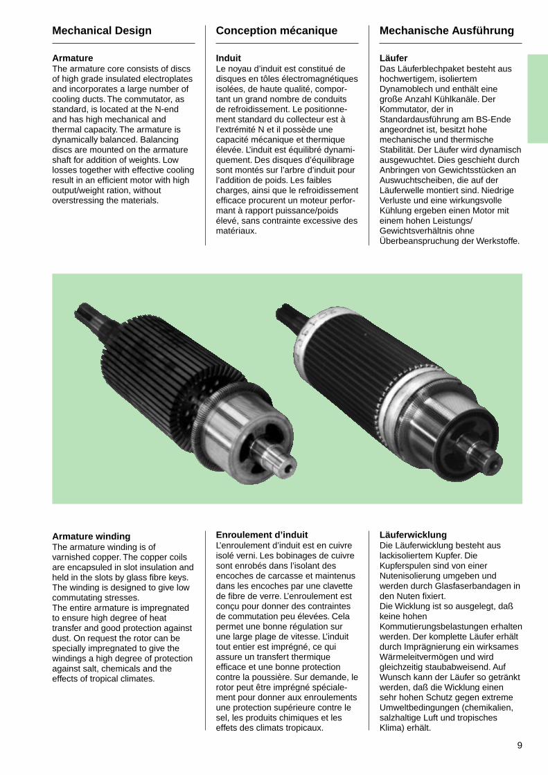
InduitLe noyau d’induit est constitué dedisques en tôles électromagnétiquesisolées, de haute qualité, compor-tant un grand nombre de conduitsde refroidissement. Le positionne-ment standard du collecteur est àl’extrémité N et il possède unecapacité mécanique et thermiqueélevée. L’induit est équilibré dynami-quement. Des disques d’équilibragesont montés sur l’arbre d’induit pourl’addition de poids. Les faiblescharges, ainsi que le refroidissementefficace procurent un moteur perfor-mant à rapport puissance/poidsélevé, sans contrainte excessive desmatériaux.
Enroulement d’induitL’enroulement d’induit est en cuivreisolé verni. Les bobinages de cuivresont enrobés dans l’isolant desencoches de carcasse et maintenusdans les encoches par une clavettede fibre de verre. L’enroulement estconçu pour donner des contraintesde commutation peu élevées. Celapermet une bonne régulation surune large plage de vitesse. L’induittout entier est imprégné, ce quiassure un transfert thermiqueefficace et une bonne protectioncontre la poussière. Sur demande, lerotor peut être imprégné spéciale-ment pour donner aux enroulementsune protection supérieure contre lesel, les produits chimiques et leseffets des climats tropicaux.
Mechanische Ausführung
LäuferDas Läuferblechpaket besteht aushochwertigem, isoliertemDynamoblech und enthält einegroße Anzahl Kühlkanäle. DerKommutator, der inStandardausführung am BS-Endeangeordnet ist, besitzt hohemechanische und thermischeStabilität. Der Läufer wird dynamischausgewuchtet. Dies geschieht durchAnbringen von Gewichtsstücken anAuswuchtscheiben, die auf derLäuferwelle montiert sind. NiedrigeVerluste und eine wirkungsvolleKühlung ergeben einen Motor miteinem hohen Leistungs/Gewichtsverhältnis ohneÜberbeanspruchung der Werkstoffe.
LäuferwicklungDie Läuferwicklung besteht auslackisoliertem Kupfer. DieKupferspulen sind von einerNutenisolierung umgeben undwerden durch Glasfaserbandagen inden Nuten fixiert.Die Wicklung ist so ausgelegt, daßkeine hohenKommutierungsbelastungen erhaltenwerden. Der komplette Läufer erhältdurch Imprägnierung ein wirksamesWärmeleitvermögen und wirdgleichzeitig staubabweisend. AufWunsch kann der Läufer so getränktwerden, daß die Wicklung einensehr hohen Schutz gegen extremeUmweltbedingungen (chemikalien,salzhaltige Luft und tropischesKlima) erhält.
Mechanical Design
ArmatureThe armature core consists of discsof high grade insulated electroplatesand incorporates a large number ofcooling ducts. The commutator, asstandard, is located at the N-endand has high mechanical andthermal capacity. The armature isdynamically balanced. Balancingdiscs are mounted on the armatureshaft for addition of weights. Lowlosses together with effective coolingresult in an efficient motor with highoutput/weight ration, withoutoverstressing the materials.
Armature windingThe armature winding is ofvarnished copper. The copper coilsare encapsuled in slot insulation andheld in the slots by glass fibre keys.The winding is designed to give lowcommutating stresses.The entire armature is impregnatedto ensure high degree of heattransfer and good protection againstdust. On request the rotor can bespecially impregnated to give thewindings a high degree of protectionagainst salt, chemicals and theeffects of tropical climates.
10
Conception mécanique
ArbreL’extrémité d’arbre standard estmunie d’une clavette. Les boutsd’arbre et les rainures de clavetagesont conformes à DIN 748, partie 3,à VSM 15273 et aux recommanda-tions CEI 72-1 ou 72-2. L’induit a unevitesse critique élevée et sa résis-tance à la flexion permet l’emploid’une transmission par courroietrapézoïdale (voir plus loin p 14).Pour les transmissions à change-ments rapides de direction ducouple, par exemple dans leslaminoirs à inversion de marche, ilpeut se produire du jeu entre arbre,clavette et accouplement. Pour évitercela, les moteurs DMP peuvent êtrecommandés avec un bout d’arbrespécial sans clavette pour lesaccouplements à ajustement àchaud.
Le couple maximum Mmax
pouvantêtre transmis par les bouts d’arbrestandards de diamètre D est indiquédans le tableau ci-dessous. Desbouts d’arbre spéciaux à couple plusélevé et des arbres en aciersspéciaux sont disponibles surdemande. Des arbres en acierspécial permettent d’augmenter lesvaleurs données ci-dessous. Lesdiamètres pour bouts d’arbresstandard sont indiqués ci-dessoussous la rubrique “D”.
Mechanical Design
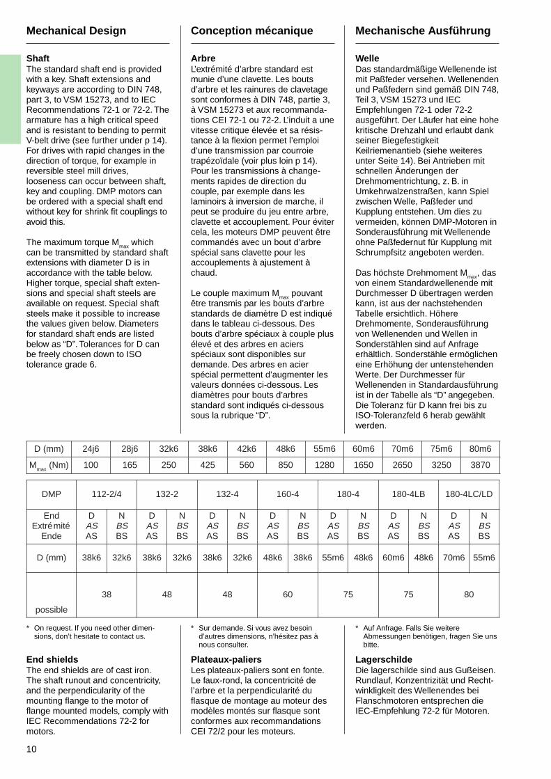
ShaftThe standard shaft end is providedwith a key. Shaft extensions andkeyways are according to DIN 748,part 3, to VSM 15273, and to IECRecommendations 72-1 or 72-2. Thearmature has a high critical speedand is resistant to bending to permitV-belt drive (see further under p 14).For drives with rapid changes in thedirection of torque, for example inreversible steel mill drives,looseness can occur between shaft,key and coupling. DMP motors canbe ordered with a special shaft endwithout key for shrink fit couplings toavoid this.
The maximum torque Mmax whichcan be transmitted by standard shaftextensions with diameter D is inaccordance with the table below.Higher torque, special shaft exten-sions and special shaft steels areavailable on request. Special shaftsteels make it possible to increasethe values given below. Diametersfor standard shaft ends are listedbelow as “D”. Tolerances for D canbe freely chosen down to ISOtolerance grade 6.
Mechanische Ausführung
WelleDas standardmäßige Wellenende istmit Paßfeder versehen. Wellenendenund Paßfedern sind gemäß DIN 748,Teil 3, VSM 15273 und IECEmpfehlungen 72-1 oder 72-2ausgeführt. Der Läufer hat eine hohekritische Drehzahl und erlaubt dankseiner BiegefestigkeitKeilriemenantieb (siehe weiteresunter Seite 14). Bei Antrieben mitschnellen Änderungen derDrehmomentrichtung, z. B. inUmkehrwalzenstraßen, kann Spielzwischen Welle, Paßfeder undKupplung entstehen. Um dies zuvermeiden, können DMP-Motoren inSonderausführung mit Wellenendeohne Paßfedernut für Kupplung mitSchrumpfsitz angeboten werden.
Das höchste Drehmoment Mmax, dasvon einem Standardwellenende mitDurchmesser D übertragen werdenkann, ist aus der nachstehendenTabelle ersichtlich. HöhereDrehmomente, Sonderausführungvon Wellenenden und Wellen inSonderstählen sind auf Anfrageerhältlich. Sonderstähle ermöglicheneine Erhöhung der untenstehendenWerte. Der Durchmesser fürWellenenden in Standardausführungist in der Tabelle als “D” angegeben.Die Toleranz für D kann frei bis zuISO-Toleranzfeld 6 herab gewähltwerden.
)mm(D 6j42 6j82 6k23 6k83 6k24 6k84 6m55 6m06 6m07 6m57 6m08
M xam )mN( 001 561 052 524 065 058 0821 0561 0562 0523 0783
* On request. If you need other dimen-sions, don’t hesitate to contact us.
End shieldsThe end shields are of cast iron.The shaft runout and concentricity,and the perpendicularity of themounting flange to the motor offlange mounted models, comply withIEC Recommendations 72-2 formotors.
* Sur demande. Si vous avez besoind’autres dimensions, n’hésitez pas ànous consulter.
Plateaux-paliersLes plateaux-paliers sont en fonte.Le faux-rond, la concentricité del’arbre et la perpendicularité duflasque de montage au moteur desmodèles montés sur flasque sontconformes aux recommandationsCEI 72/2 pour les moteurs.
* Auf Anfrage. Falls Sie weitereAbmessungen benötigen, fragen Sie unsbitte.
LagerschildeDie lagerschilde sind aus Gußeisen.Rundlauf, Konzentrizität und Recht-winkligkeit des Wellenendes beiFlanschmotoren entsprechen dieIEC-Empfehlung 72-2 für Motoren.
PMD 4/2-211 2-231 4-231 4-061 4-081 BL4-081 DL/CL4-081
dnEétimértxE
ednE
DSASA
NSBSB
DSASA
NSBSB
DSASA
NSBSB
DSASA
NSBSB
DSASA
NSBSB
DSASA
NSBSB
DSASA
NSBSB
)mm(D 6k83 6k23 6k83 6k23 6k83 6k23 6k84 6k83 6m55 6k84 6m06 6k84 6m07 6m55
elbissop
83 84 84 06 57 57 08
11
Conception mécanique
Trous de drainagepour moteurs fermésLes moteurs DMP sont munis detrous de drainage situés dans lesplateaux-paliers suivant la figure ci-dessous.
Montage horizontal
Montage vertical
Ensemble porte-balaisL’ensemble porte-balais est basé surune bague isolante sur laquelle sontmontés les bras de balais. Lesporte-balais contiennent des doigtsde pression rappelés par ressort.Il est facile de faire tourner l’ensem-ble porte-balais quand un change-ment de balais devient nécessaire.Il n’y a pas lieu de spécifier le sensde rotation des moteurs DMP. Sitoutefois le sens de rotation requisest indiqué dans la commande, laposition de l’ensemble porte-balaissera optimisée pour donner laprotection maximum contre lesperturbations de commutation.
Mechanical Design
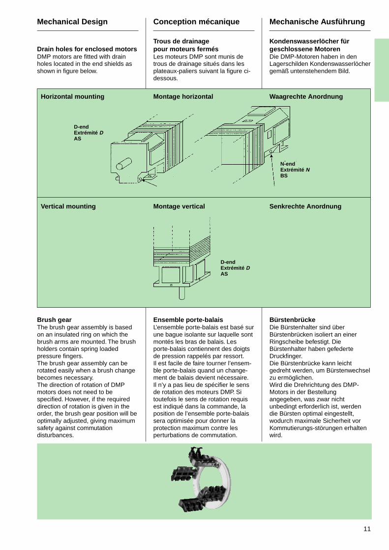
Drain holes for enclosed motorsDMP motors are fitted with drainholes located in the end shields asshown in figure below.
Horizontal mounting
Vertical mounting
Brush gearThe brush gear assembly is basedon an insulated ring on which thebrush arms are mounted. The brushholders contain spring loadedpressure fingers.The brush gear assembly can berotated easily when a brush changebecomes necessary.The direction of rotation of DMPmotors does not need to bespecified. However, if the requireddirection of rotation is given in theorder, the brush gear position will beoptimally adjusted, giving maximumsafety against commutationdisturbances.
Mechanische Ausführung
Kondenswasserlöcher fürgeschlossene MotorenDie DMP-Motoren haben in denLagerschilden Kondenswasserlöchergemäß untenstehendem Bild.
Waagrechte Anordnung
Senkrechte Anordnung
BürstenbrückeDie Bürstenhalter sind überBürstenbrücken isoliert an einerRingscheibe befestigt. DieBürstenhalter haben gefederteDruckfinger.Die Bürstenbrücke kann leichtgedreht werden, um Bürstenwechselzu ermöglichen.Wird die Drehrichtung des DMP-Motors in der Bestellungangegeben, was zwar nichtunbedingt erforderlich ist, werdendie Bürsten optimal eingestellt,wodurch maximale Sicherheit vorKommutierungs-störungen erhaltenwird.
D-endExtrémité DAS
N-endExtrémité NBS
D-endExtrémité DAS
12
Conception mécanique
Boîtier de raccordement etentrée de câbleLa position standard du boîtier deconnexion est sur la droite dumoteur DMP (face à l’extrémité D).Le boîtier de raccordement peutaussi se placer soit sur le dessus,soit à gauche de la machine, vue del’extrémité D. Le câble peut êtreintroduit par dessus ou par dessous,sauf pour DMP 112 et 132, pourlesquels l’entrée de câble se faitcôté bout d’arbre. La positionrequise pour la boîte à bornes doitêtre spécifiée à la commande. Lesmoteurs DMP sont livrés avec degrandes boîtes à bornes IP 55équipées de capsules :
• pour DMP 112 et 132 :2 x Ø 28,5 (PG 21)
+ 2 x Ø 20,5 (PG 13,5),
• pour DMP 160 et 180 :2 x Ø 55 (PG 42)
+ 4 x Ø 28,5 (PG 21).Les marquages des bornes sontconformes aux recommandations deCEI Publ. 34-8.
Sur tous les moteurs, la vis deterre est dans la boîte à bornes(suivant le standard CEI).
Mechanical Design
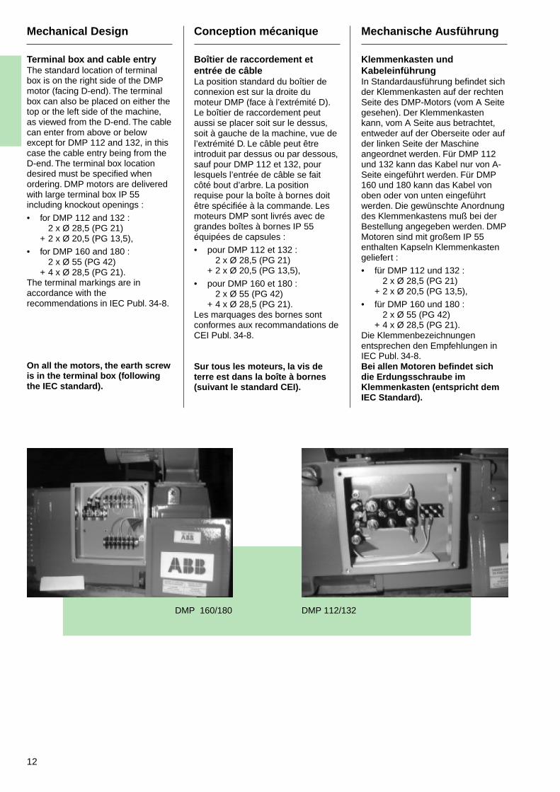
Terminal box and cable entryThe standard location of terminalbox is on the right side of the DMPmotor (facing D-end). The terminalbox can also be placed on either thetop or the left side of the machine,as viewed from the D-end. The cablecan enter from above or belowexcept for DMP 112 and 132, in thiscase the cable entry being from theD-end. The terminal box locationdesired must be specified whenordering. DMP motors are deliveredwith large terminal box IP 55including knockout openings :
• for DMP 112 and 132 :2 x Ø 28,5 (PG 21)
+ 2 x Ø 20,5 (PG 13,5),
• for DMP 160 and 180 :2 x Ø 55 (PG 42)
+ 4 x Ø 28,5 (PG 21).The terminal markings are inaccordance with therecommendations in IEC Publ. 34-8.
On all the motors, the earth screwis in the terminal box (followingthe IEC standard).
Mechanische Ausführung
Klemmenkasten undKabeleinführungIn Standardausführung befindet sichder Klemmenkasten auf der rechtenSeite des DMP-Motors (vom A Seitegesehen). Der Klemmenkastenkann, vom A Seite aus betrachtet,entweder auf der Oberseite oder aufder linken Seite der Maschineangeordnet werden. Für DMP 112und 132 kann das Kabel nur von A-Seite eingeführt werden. Für DMP160 und 180 kann das Kabel vonoben oder von unten eingeführtwerden. Die gewünschte Anordnungdes Klemmenkastens muß bei derBestellung angegeben werden. DMPMotoren sind mit großem IP 55enthalten Kapseln Klemmenkastengeliefert :
• für DMP 112 und 132 :2 x Ø 28,5 (PG 21)
+ 2 x Ø 20,5 (PG 13,5),
• für DMP 160 und 180 :2 x Ø 55 (PG 42)
+ 4 x Ø 28,5 (PG 21).Die Klemmenbezeichnungenentsprechen den Empfehlungen inIEC Publ. 34-8.Bei allen Motoren befindet sichdie Erdungsschraube imKlemmenkasten (entspricht demIEC Standard).
DMP 160/180 DMP 112/132
13
Mechanical Design
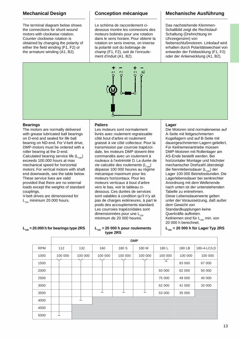
The terminal diagram below showsthe connections for shunt woundmotors with clockwise rotation.Counter clockwise rotation isobtained by changing the polarity ofeither the field winding (F1, F2) orthe armature winding (A1, B2).
BearingsThe motors are normally deliveredwith grease lubricated ball bearingson D-end and sealed for life ballbearing on ND-end. For V-belt drive,DMP-motors must be ordered with aroller bearing at the D-end.Calculated bearing service life (L10h)exceeds 100.000 hours at maxmechanical speed for horizontalmotors. For vertical motors with shaftend downwards, see the table below.These service lives are validprovided that there are no externalloads except the weights of standardcouplings.V-belt drives are dimensioned forL
10h minimum 20.000 hours.
L10h = 20.000 h for bearings type 2RS
Conception mécanique
Le schéma de raccordement ci-dessous montre les connexions desmoteurs bobinés pour une rotationdans le sens horaire. Pour obtenir larotation en sens inverse, on inversela polarité soit du bobinage dechamp (F1, F2), soit de l’enroule-ment d’induit (A1, B2).
PaliersLes moteurs sont normalementlivrés avec roulement regraissablecôté bout d’arbre et roulementgraissé à vie côté collecteur. Pour latransmission par courroie trapézoï-dale, les moteurs DMP doivent êtrecommandés avec un roulement àrouleaux à l’extrémité D. La durée devie calculée des roulements (L10h)dépasse 100 000 heures au régimemécanique maximum pour lesmoteurs horizontaux. Pour lesmoteurs verticaux à bout d’arbrevers le bas, voir le tableau ci-dessous. Ces durées de servicessont valables à condition qu’il n’y aitpas de charges extérieures, à part lepoids des accouplements standard.Les courroies trapézoïdales sontdimensionnées pour une L
10hminimum de 20 000 heures.
L10h = 20 000 h pour roulementstype 2RS
Mechanische Ausführung
Das nachstehende Klemmen-Schaltbild zeigt die Rechtslauf-Schaltung (Drehrichtung imUhrzeigersinn) vonNebenschlußmotoren. Linkslauf wirderhalten durch Polaritätswechsel vonentweder der Feldwicklung (F1, F2)oder der Ankerwicklung (A1, B2).
LagerDie Motoren sind normalerweise aufA-Seite mit fettgeschmiertenKugellagern und auf B-Seite mitdauergeschmierten Lagern geliefert.Für Keilriemenantriebe müssenDMP-Motoren mit Rollenlager amAS-Ende bestellt werden. Beihorizontaler Montage und höchstermechanischer Drehzahl übersteigtdie Nennlebensdauer (L10h) derLager 100 000 Betriebsstunden. DieLagerlebensdauer bei senkrechterAnordnung mit dem Wellenendenach unten ist der untenstehendenTabelle zu entnehmen.Diese Lebensdauerwerte geltenunter der Voraussetzung, daß außerdem Gewicht vonStandardkupplungen keineQuerkräfte auftreten.Keilriemen sind für L10h min. von20 000 h berechnet.
L10h = 20 000 h für Lager Typ 2RS
PMD
MPR 211 231 061 S081 M081 L081 BL081 DL/CL-4-081
0001 000001 000001 000001 000001 000001 000001 000001 000001
0051 00038 00076
0002 00039 00026 00005
0052 00057 00094 00004
0003 00026 00014 00033
0053 00035 00053
0004
0054
0005
14
Mechanical Design
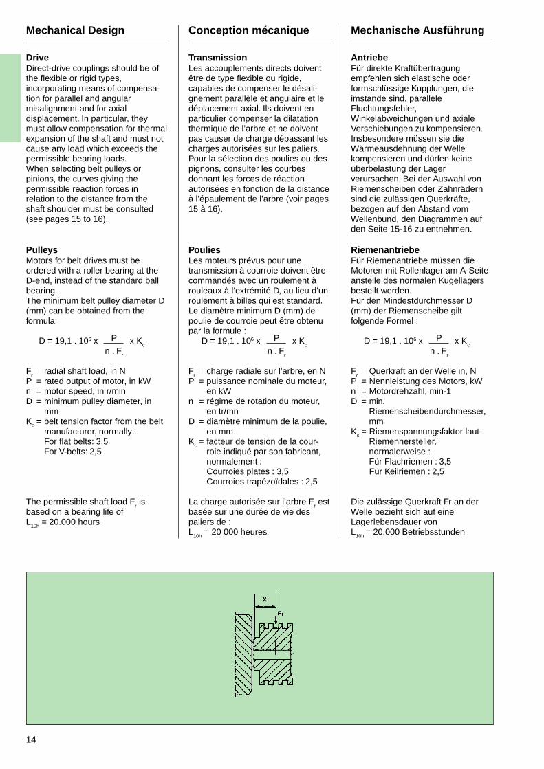
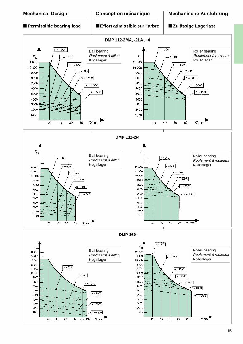
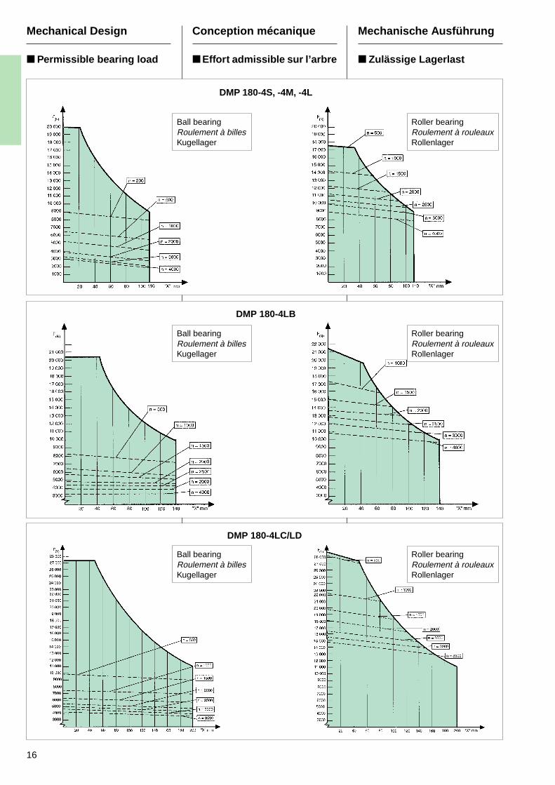
DriveDirect-drive couplings should be ofthe flexible or rigid types,incorporating means of compensa-tion for parallel and angularmisalignment and for axialdisplacement. In particular, theymust allow compensation for thermalexpansion of the shaft and must notcause any load which exceeds thepermissible bearing loads.When selecting belt pulleys orpinions, the curves giving thepermissible reaction forces inrelation to the distance from theshaft shoulder must be consulted(see pages 15 to 16).
PulleysMotors for belt drives must beordered with a roller bearing at theD-end, instead of the standard ballbearing.The minimum belt pulley diameter D(mm) can be obtained from theformula:
D = 19,1 . 106 x P x Kcn . Fr
Fr = radial shaft load, in NP = rated output of motor, in kWn = motor speed, in r/minD = minimum pulley diameter, in
mmKc = belt tension factor from the belt
manufacturer, normally:For flat belts: 3,5For V-belts: 2,5
The permissible shaft load Fr is
based on a bearing life ofL10h = 20.000 hours
Conception mécanique
TransmissionLes accouplements directs doiventêtre de type flexible ou rigide,capables de compenser le désali-gnement parallèle et angulaire et ledéplacement axial. Ils doivent enparticulier compenser la dilatationthermique de l’arbre et ne doiventpas causer de charge dépassant lescharges autorisées sur les paliers.Pour la sélection des poulies ou despignons, consulter les courbesdonnant les forces de réactionautorisées en fonction de la distanceà l’épaulement de l’arbre (voir pages15 à 16).
PouliesLes moteurs prévus pour unetransmission à courroie doivent êtrecommandés avec un roulement àrouleaux à l’extrémité D, au lieu d’unroulement à billes qui est standard.Le diamètre minimum D (mm) depoulie de courroie peut être obtenupar la formule :
D = 19,1 . 106 x P x Kcn . Fr
Fr = charge radiale sur l’arbre, en NP = puissance nominale du moteur,
en kWn = régime de rotation du moteur,
en tr/mnD = diamètre minimum de la poulie,
en mmK
c= facteur de tension de la cour-
roie indiqué par son fabricant,normalement :Courroies plates : 3,5Courroies trapézoïdales : 2,5
La charge autorisée sur l’arbre Fr est
basée sur une durée de vie despaliers de :L
10h = 20 000 heures
Mechanische Ausführung
AntriebeFür direkte Kraftübertragungempfehlen sich elastische oderformschlüssige Kupplungen, dieimstande sind, paralleleFluchtungsfehler,Winkelabweichungen und axialeVerschiebungen zu kompensieren.Insbesondere müssen sie dieWärmeausdehnung der Wellekompensieren und dürfen keineüberbelastung der Lagerverursachen. Bei der Auswahl vonRiemenscheiben oder Zahnrädernsind die zulässigen Querkräfte,bezogen auf den Abstand vomWellenbund, den Diagrammen aufden Seite 15-16 zu entnehmen.
RiemenantriebeFür Riemenantriebe müssen dieMotoren mit Rollenlager am A-Seiteanstelle des normalen Kugellagersbestellt werden.Für den Mindestdurchmesser D(mm) der Riemenscheibe giltfolgende Formel :
D = 19,1 . 106 x P x Kcn . Fr
Fr = Querkraft an der Welle in, NP = Nennleistung des Motors, kWn = Motordrehzahl, min-1D = min.
Riemenscheibendurchmesser,mm
Kc = Riemenspannungsfaktor lautRiemenhersteller,normalerweise :Für Flachriemen : 3,5Für Keilriemen : 2,5
Die zulässige Querkraft Fr an derWelle bezieht sich auf eineLagerlebensdauer vonL
10h = 20.000 Betriebsstunden
15
DMP 112-2MA, -2LA , -4
Roller bearingRoulement à rouleauxRollenlager
Ball bearingRoulement à billesKugellager
Mechanical Design
Permissible bearing load
Conception mécanique
Effort admissible sur l’arbre
Mechanische Ausführung
Zulässige Lagerlast
DMP 132-2/4
Roller bearingRoulement à rouleauxRollenlager
Ball bearingRoulement à billesKugellager
DMP 160
Ball bearingRoulement à billesKugellager
Roller bearingRoulement à rouleauxRollenlager
16
Mechanical Design
Permissible bearing load
Conception mécanique
Effort admissible sur l’arbre
Mechanische Ausführung
Zulässige Lagerlast
DMP 180-4S, -4M, -4L
DMP 180-4LB
Roller bearingRoulement à rouleauxRollenlager
Ball bearingRoulement à billesKugellager
Roller bearingRoulement à rouleauxRollenlager
Ball bearingRoulement à billesKugellager
DMP 180-4LC/LD
Roller bearingRoulement à rouleauxRollenlager
Ball bearingRoulement à billesKugellager
17
IM 101 x
1-nimnm/rt
pr m
PMD
005 0001 0051 0002 0052 0003
)N( )N( )N( )N( )N( )N(
211 0221 088 077 066 045 094
231 0861 0031 0501 578 007 066
061 0672 0602 0171 0631 0021 0001
081 0103 0712 0691 0161 0031 0011
DL/CL081 0092 0051 057 004 – –
Fa = additionalaxial load
Fa = charge axialesupplémentaire
Fa = Zusätzlicheaxiale Belastung
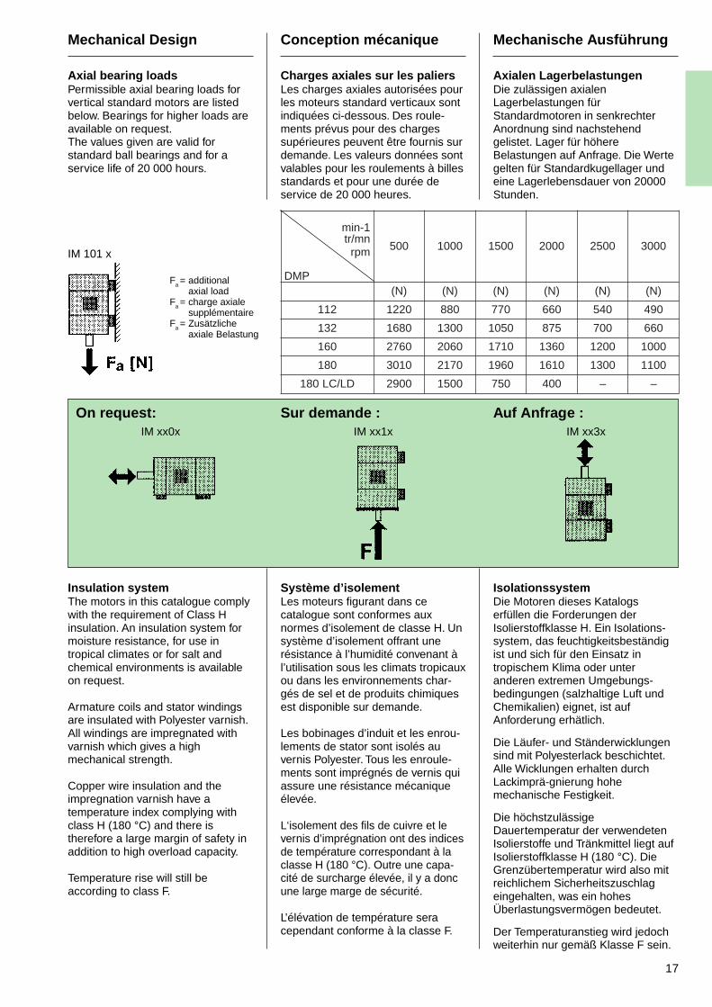
Mechanical Design
Axial bearing loadsPermissible axial bearing loads forvertical standard motors are listedbelow. Bearings for higher loads areavailable on request.The values given are valid forstandard ball bearings and for aservice life of 20 000 hours.
On request:IM xx0x
Insulation systemThe motors in this catalogue complywith the requirement of Class Hinsulation. An insulation system formoisture resistance, for use intropical climates or for salt andchemical environments is availableon request.
Armature coils and stator windingsare insulated with Polyester varnish.All windings are impregnated withvarnish which gives a highmechanical strength.
Copper wire insulation and theimpregnation varnish have atemperature index complying withclass H (180 °C) and there istherefore a large margin of safety inaddition to high overload capacity.
Temperature rise will still beaccording to class F.
Conception mécanique
Charges axiales sur les paliersLes charges axiales autorisées pourles moteurs standard verticaux sontindiquées ci-dessous. Des roule-ments prévus pour des chargessupérieures peuvent être fournis surdemande. Les valeurs données sontvalables pour les roulements à billesstandards et pour une durée deservice de 20 000 heures.
Sur demande :IM xx1x
Système d’isolementLes moteurs figurant dans cecatalogue sont conformes auxnormes d’isolement de classe H. Unsystème d’isolement offrant unerésistance à l’humidité convenant àl’utilisation sous les climats tropicauxou dans les environnements char-gés de sel et de produits chimiquesest disponible sur demande.
Les bobinages d’induit et les enrou-lements de stator sont isolés auvernis Polyester. Tous les enroule-ments sont imprégnés de vernis quiassure une résistance mécaniqueélevée.
L‘isolement des fils de cuivre et levernis d’imprégnation ont des indicesde température correspondant à laclasse H (180 °C). Outre une capa-cité de surcharge élevée, il y a doncune large marge de sécurité.
L’élévation de température seracependant conforme à la classe F.
Mechanische Ausführung
Axialen LagerbelastungenDie zulässigen axialenLagerbelastungen fürStandardmotoren in senkrechterAnordnung sind nachstehendgelistet. Lager für höhereBelastungen auf Anfrage. Die Wertegelten für Standardkugellager undeine Lagerlebensdauer von 20000Stunden.
Auf Anfrage :IM xx3x
IsolationssystemDie Motoren dieses Katalogserfüllen die Forderungen derIsolierstoffklasse H. Ein Isolations-system, das feuchtigkeitsbeständigist und sich für den Einsatz intropischem Klima oder unteranderen extremen Umgebungs-bedingungen (salzhaltige Luft undChemikalien) eignet, ist aufAnforderung erhätlich.
Die Läufer- und Ständerwicklungensind mit Polyesterlack beschichtet.Alle Wicklungen erhalten durchLackimprä-gnierung hohemechanische Festigkeit.
Die höchstzulässigeDauertemperatur der verwendetenIsolierstoffe und Tränkmittel liegt aufIsolierstoffklasse H (180 °C). DieGrenzübertemperatur wird also mitreichlichem Sicherheitszuschlageingehalten, was ein hohesÜberlastungsvermögen bedeutet.
Der Temperaturanstieg wird jedochweiterhin nur gemäß Klasse F sein.
18
Mechanical design
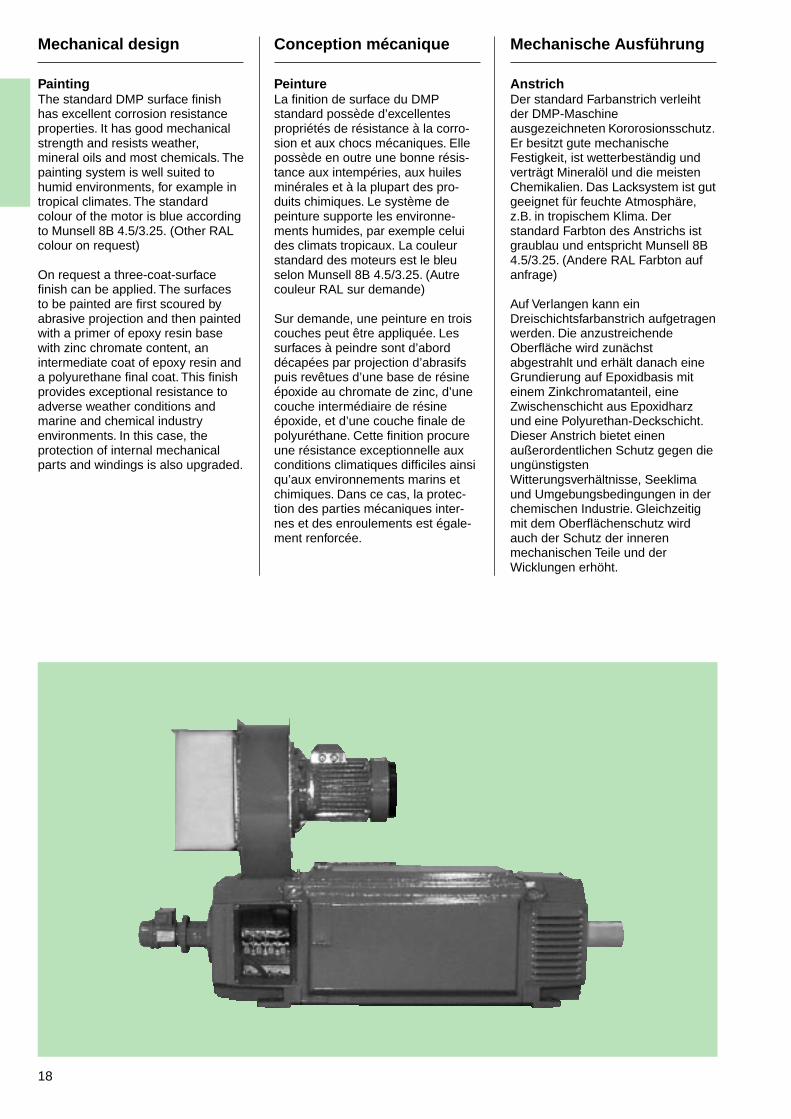
PaintingThe standard DMP surface finishhas excellent corrosion resistanceproperties. It has good mechanicalstrength and resists weather,mineral oils and most chemicals. Thepainting system is well suited tohumid environments, for example intropical climates. The standardcolour of the motor is blue accordingto Munsell 8B 4.5/3.25. (Other RALcolour on request)
On request a three-coat-surfacefinish can be applied. The surfacesto be painted are first scoured byabrasive projection and then paintedwith a primer of epoxy resin basewith zinc chromate content, anintermediate coat of epoxy resin anda polyurethane final coat. This finishprovides exceptional resistance toadverse weather conditions andmarine and chemical industryenvironments. In this case, theprotection of internal mechanicalparts and windings is also upgraded.
Conception mécanique
PeintureLa finition de surface du DMPstandard possède d’excellentespropriétés de résistance à la corro-sion et aux chocs mécaniques. Ellepossède en outre une bonne résis-tance aux intempéries, aux huilesminérales et à la plupart des pro-duits chimiques. Le système depeinture supporte les environne-ments humides, par exemple celuides climats tropicaux. La couleurstandard des moteurs est le bleuselon Munsell 8B 4.5/3.25. (Autrecouleur RAL sur demande)
Sur demande, une peinture en troiscouches peut être appliquée. Lessurfaces à peindre sont d’aborddécapées par projection d’abrasifspuis revêtues d’une base de résineépoxide au chromate de zinc, d’unecouche intermédiaire de résineépoxide, et d’une couche finale depolyuréthane. Cette finition procureune résistance exceptionnelle auxconditions climatiques difficiles ainsiqu’aux environnements marins etchimiques. Dans ce cas, la protec-tion des parties mécaniques inter-nes et des enroulements est égale-ment renforcée.
Mechanische Ausführung
AnstrichDer standard Farbanstrich verleihtder DMP-Maschineausgezeichneten Kororosionsschutz.Er besitzt gute mechanischeFestigkeit, ist wetterbeständig undverträgt Mineralöl und die meistenChemikalien. Das Lacksystem ist gutgeeignet für feuchte Atmosphäre,z.B. in tropischem Klima. Derstandard Farbton des Anstrichs istgraublau und entspricht Munsell 8B4.5/3.25. (Andere RAL Farbton aufanfrage)
Auf Verlangen kann einDreischichtsfarbanstrich aufgetragenwerden. Die anzustreichendeOberfläche wird zunächstabgestrahlt und erhält danach eineGrundierung auf Epoxidbasis miteinem Zinkchromatanteil, eineZwischenschicht aus Epoxidharzund eine Polyurethan-Deckschicht.Dieser Anstrich bietet einenaußerordentlichen Schutz gegen dieungünstigstenWitterungsverhältnisse, Seeklimaund Umgebungsbedingungen in derchemischen Industrie. Gleichzeitigmit dem Oberflächenschutz wirdauch der Schutz der innerenmechanischen Teile und derWicklungen erhöht.
19
90
2
1
3
80
75
7268
651 2,5 5 2 3 4 5 6 7 8 9101 102
Mechanical design
BalancingThe motors conform to grade Naccording to ISO 2373.On request, motors with length Sand M can be balanced to grade R(other lengths or class S: contactABB). DMP motors are balancedwith half key.
VibrationsFor disturbance-free commutation,the following vibration values shouldnot be exceeded.
Vibration Vibration valuefrequencyHz
≤ 100 VibrationvelocityVrms ≤ 4,5 mm/s
> 100 Vibrationaccelerationâ ≤ 4 m/s2
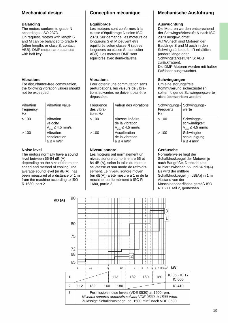
Noise levelThe motors normally have a soundlevel between 65-84 dB (A),depending on the size of the motor,speed and method of cooling. Theaverage sound level (in dB(A)) hasbeen measured at a distance of 1 mfrom the machine according to ISOR 1680, part 2.
Conception mécanique
EquilibrageLes moteurs sont conformes à laclasse d’équilibrage N selon ISO2373. Sur demande, les moteurs delongueurs S et M peuvent êtreéquilibrés selon classe R (autreslongueurs ou classe S : consulterABB). Les moteurs DMP sontéquilibrés avec demi-clavette.
VibrationsPour obtenir une commutation sansperturbations, les valeurs de vibra-tions suivantes ne doivent pas êtredépassées
Fréquence Valeur des vibrationsdes vibra-tions Hz
≤ 100 Vitesse linéairede la vibrationVrms ≤ 4,5 mm/s
> 100 Accélérationde la vibrationâ ≤ 4 m/s2
Niveau sonoreLes moteurs ont normalement unniveau sonore compris entre 65 et84 dB (A), selon la taille du moteur,sa vitesse et son mode de refroidis-sement. Le niveau sonore moyen(en dB(A)) a été mesuré à 1 m de lamachine, conformément à ISO R1680, partie 2.
Mechanische Ausführung
AuswuchtungDie Motoren werden entsprechendder Schwingstärkestufe N nach ISO2373 ausgewuchtet.Auf Wunsch sind Motoren derBaulänge S und M auch in denSchwingstärkestufen R erhältlich(andere länge oderSchwingstärkestufen S: ABBzurückfragen).Die DMP-Motoren werden mit halberPaßfeder ausgewuchtet.
SchwingungenUm eine störungsfreieKommutierung sicherzustellen,sollten folgende Schwingungswertenicht überschritten werden :
Schwingungs- Schwingungs-Frequenz werteHz
≤ 100 Schwingge-schwindigkeitVrms ≤ 4,5 mm/s
> 100 Schwingbe-schleunigungâ ≤ 4 m/s2
GeräuscheNormalerweise liegt derSchalldruckpegel der Motoren jenach Baugröße, Drehzahl undKühlart zwischen 65 und 84 dB(A).Es wird der mittlereSchalldruckpegel [in dB(A)] in 1 mAbstand von derMaschinenoberfläche gemäß ISOR 1680, Teil 2, gemessen.
dB (A)
kW
1 112 132 160 180 IC 06 - IC 17IC 666
2 112 132 160 180 IC 410
3 Permissible noise levels (VDE 0530) at 1500 rpm.Niveaux sonores autorisés suivant VDE 0530, à 1500 tr/mn.Zulässige Schalldruckpegel bei 1500 min-1 nach VDE 0530.
20
Mechanical Design
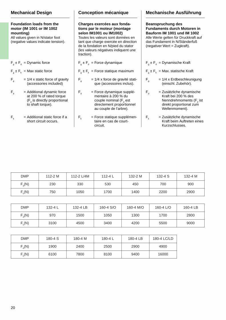
Foundation loads from themotor (IM 1001 or IM 1002mounting)All values given in N/stator foot(negative values indicate tension).
Fg ± Fd = Dynamic force
Fg ± Fk = Max static force
Fg
= 1/4 x static force of gravity(accessories included)
Fd
= Additional dynamic forceat 200 % of rated torque(Fd is directly proportionalto shaft torque).
Fk
= Additional static force if ashort circuit occurs.
Conception mécanique
Charges exercées aux fonda-tions par le moteur (montageselon IM1001 ou IM1002)Toutes les valeurs sont données entant que charge exercée en directionde la fondation en N/pied du stator(les valeurs négatives indiquent unetraction).
Fg ± Fd = Force dynamique
Fg ± Fk = Force statique maximum
Fg
= 1/4 x force de gravité stati-que (accessoires inclus).
Fd
= Force dynamique supplé-mentaire à 200 % ducouple nominal (Fd estdirectement proportionnelau couple de l’arbre).
Fk
= Force statique supplémen-taire en cas de court-circuit.
Mechanische Ausführung
Beanspruchung desFundaments durch Motoren inBauform IM 1001 und IM 1002Alle Werte gelten für Druckkraft aufdas Fundament in N/Ständerfuß(negativer Wert = Zugkraft).
Fg ± Fd = Dynamische Kraft
Fg ± Fk = Max. statische Kraft
Fg
= 1/4 x Erdbeschleunigung(einschl. Zubehör).
Fd
= Zusätzliche dynamischeKraft bei 200 % desNenndrehmoments (Fd istdirekt proportional zumWellenmoment).
Fk
= Zusätzliche dynamischeKraft beim Auftreten einesKurzschlusses.
PMD M2-211 M4/L2-211 L4-211 M2-231 S4-231 M4-231
Fd )N( 032 033 035 054 007 009
Fk )N( 057 0501 0071 0041 0022 0092
PMD L4-231 BL4-231 O/S4-061 O/M4-061 O/L4-061 BL4-061
Fd )N( 079 0051 0501 0031 0071 0082
Fk )N( 0013 0054 0043 0024 0055 0009
PMD S4-081 M4-081 L4-081 BL4-081 DL/CL4-081
Fd )N( 0091 0042 0052 0092 0094
Fk )N( 0016 0087 0018 0049 00061
21
Electrical Design
Definitions
Base speedThe rated motor speed at ratedoutput, rated voltage, full excitationand normal operating temperature.
The tolerance for standard motorswith shunt winding is ± 5 %.
Field weakening rangeThe ratio of the maximum electricalspeed to the base speed.Permissible field weakening range ismax 1:3 for DMP 112-180.Higher field weakening values canbe supplied on request.
Max. mechanical speedThe speed to which the motor islimited by mechanical factors.
Max. electrical speed (n 2)The highest speed which can bequoted for a given applicationwithout reduction of armaturecurrent.
Conception électrique
Définitions
Vitesse de baseLa vitesse nominale du moteur àpuissance nominale, tension nomi-nale, excitation maximum et tempé-rature de service normale.
La tolérance pour les moteursstandard avec enroulement dedérivation est de ± 5 %.
Plage de désexcitationRapport de la vitesse électrique maxi-mum à la vitesse de base. Le rapportmaximum autorisé de désexcitationest 1:3 pour DMP 112-180.Des valeurs de désexcitation supé-rieures peuvent être fournies surdemande.
Vitesse mécanique maximumLa vitesse à laquelle le moteur estlimité par les facteurs mécaniques.
Vitesse électrique maximum (n 2)La vitesse la plus élevée qui peutêtre indiquée pour une applicationdonnée sans réduction du courantinduit.
Elektrische Ausführung
Definitionen
GrunddrehzahlNenndrehzahl des Motors beiNennleistung, Nennspannung, vollerErregung und normalerBetriebstemperatur.
Das Toleranzfeld für Motoren mitNebenschlußwicklung beträgt ± 5 %.
FeldschwächbereichBereich zwischen höchsterelektrischer Drehzahl undGrunddrehzahl. Für DMP 112-180ist ein Feldschwächbereich von max.1:3 zulässig. Auf Anfrage könnenhöhere Feldschwächungswerteangeboten Werden.
Höchste mechanische DrehzahlObere Drehzahlgrenze mit Rücksichtauf mechanische Belastung.
Höchste elektrische Drehzahl (n 2)Obere Drehzahlgrenze mit Rücksichtauf einen gewissen Betriebsfall undohne Verringerung des Ankerstroms.
22
Electrical Design
Max. operating speedThe max. operating motor speed asprinted on the name plate.
Armature voltageMax. permissible armature voltagefor open forms motor types DMP112-4, 160, 180 is 550 V. For allother forms and types the max.permissible armature voltage is620 V. For higher voltages thanthose given please consult ABB.Max. network voltage = 500 V.
ExcitationStandard motors are delivered withseparate excitation. The standardvoltages are between 110 V and440 V except for 2 pole motors inclosed forms for which the max.excitation voltage is 220 V.
When the excitation voltage issupplied from a converter, fieldforcing voltage of up to 1,5 times therated value may be applied to amaximum of 660 V. With cold fieldwindings the current can be up to40 % higher than the rated fieldcurrent. Higher field forcing onrequest.
Conception électrique
Vitesse maximum de serviceLa vitesse maximum autorisée dumoteur, imprimée sur la plaquesignalétique.
Tension d’induitLa tension d’induit max. autoriséepour les moteurs ouverts de typesDMP 112-4, 160, 180 est de 550 V.Pour les autres types, elle est de620 V. Pour des tensions supérieuresà celles indiquées, consulter ABB.Tension max. du réseau = 500 V.
ExcitationLes moteurs sont normalementlivrés avec excitation séparée. Lestensions standard sont comprisesentre 110 V et 440 V, sauf pour lesmoteurs bipolaires de type fermépour lesquels la tension d’excitationmaximum est de 220 V.
Lorsque la tension d’excitation estfournie par un convertisseur, unetension de forçage de champpouvant atteindre 1,5 fois la tensionnominale peut être appliquéejusqu’à un maximum de 660 V. Avecles enroulements de champ froids,le courant peut être jusqu’à 40 %supérieur au courant de champnominal. Forçage de champ supé-rieur sur demande.
Elektrische Ausführung
Höchste BetriebsdrehzahlHöchstzulässige Drehzahl gemäßdem am Motor angebrachtenLeistungsschild.
AnkerspannungFür offenen Motoren Typ DMP 112-4,160, 180 ist die max. ZulässigeAnkerspannung 550 V Gs. Bei allenanderen Fälle, gilt eine max.Ankerspannung von 620 V Gs. Fürhöhere Spannungen ist bei ABBrückzufragen. Max. Netzspannung :500 V Ds.
ErregungIn normaler Ausführung sind dieMotoren fremderregt und werden fürSpannungen zwischen 110 und 440V ausgelegt. Eine Ausnahme bilden2 polige Motoren oberflächengekühlter(geschlossener) Ausführung, derenmax. Erregerspannung 220 Vbeträgt.
Bei Stromrichterspeisung istStoßerregung mit max. 1,5 facherNennspannung (aber nicht über660 V) zulässig. Bei kalten Motorenkann sich die Erregerleistung bis zu40 % des Nennwerts erhöhen.Auslegung für höhere Stoßerregungwird auf Wunsch angeboten.
23
Electrical Design
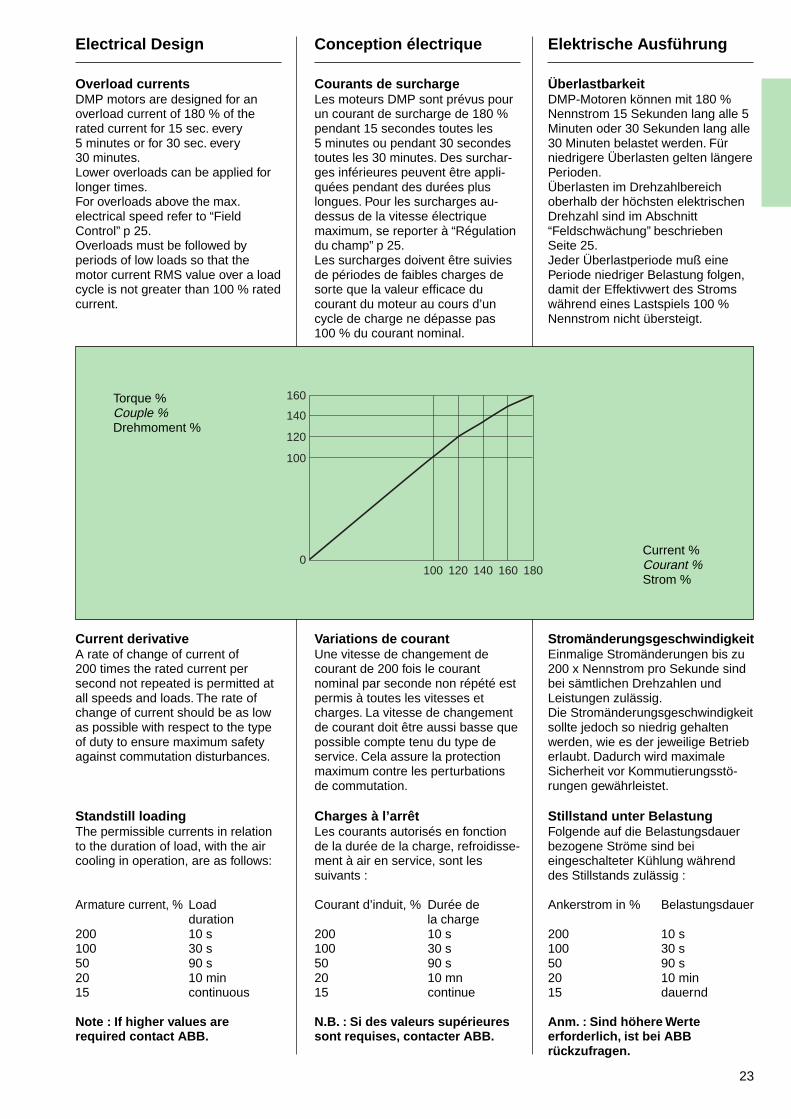
Overload currentsDMP motors are designed for anoverload current of 180 % of therated current for 15 sec. every5 minutes or for 30 sec. every30 minutes.Lower overloads can be applied forlonger times.For overloads above the max.electrical speed refer to “FieldControl” p 25.Overloads must be followed byperiods of low loads so that themotor current RMS value over a loadcycle is not greater than 100 % ratedcurrent.
Current derivativeA rate of change of current of200 times the rated current persecond not repeated is permitted atall speeds and loads. The rate ofchange of current should be as lowas possible with respect to the typeof duty to ensure maximum safetyagainst commutation disturbances.
Standstill loadingThe permissible currents in relationto the duration of load, with the aircooling in operation, are as follows:
Armature current, % Loadduration
200 10 s100 30 s50 90 s20 10 min15 continuous
Note : If higher values arerequired contact ABB.
Conception électrique
Courants de surchargeLes moteurs DMP sont prévus pourun courant de surcharge de 180 %pendant 15 secondes toutes les5 minutes ou pendant 30 secondestoutes les 30 minutes. Des surchar-ges inférieures peuvent être appli-quées pendant des durées pluslongues. Pour les surcharges au-dessus de la vitesse électriquemaximum, se reporter à “Régulationdu champ” p 25.Les surcharges doivent être suiviesde périodes de faibles charges desorte que la valeur efficace ducourant du moteur au cours d’uncycle de charge ne dépasse pas100 % du courant nominal.
Variations de courantUne vitesse de changement decourant de 200 fois le courantnominal par seconde non répété estpermis à toutes les vitesses etcharges. La vitesse de changementde courant doit être aussi basse quepossible compte tenu du type deservice. Cela assure la protectionmaximum contre les perturbationsde commutation.
Charges à l’arrêtLes courants autorisés en fonctionde la durée de la charge, refroidisse-ment à air en service, sont lessuivants :
Courant d’induit, % Durée dela charge
200 10 s100 30 s50 90 s20 10 mn15 continue
N.B. : Si des valeurs supérieuressont requises, contacter ABB.
Elektrische Ausführung
ÜberlastbarkeitDMP-Motoren können mit 180 %Nennstrom 15 Sekunden lang alle 5Minuten oder 30 Sekunden lang alle30 Minuten belastet werden. Fürniedrigere Überlasten gelten längerePerioden.Überlasten im Drehzahlbereichoberhalb der höchsten elektrischenDrehzahl sind im Abschnitt“Feldschwächung” beschriebenSeite 25.Jeder Überlastperiode muß einePeriode niedriger Belastung folgen,damit der Effektivwert des Stromswährend eines Lastspiels 100 %Nennstrom nicht übersteigt.
StromänderungsgeschwindigkeitEinmalige Stromänderungen bis zu200 x Nennstrom pro Sekunde sindbei sämtlichen Drehzahlen undLeistungen zulässig.Die Stromänderungsgeschwindigkeitsollte jedoch so niedrig gehaltenwerden, wie es der jeweilige Betrieberlaubt. Dadurch wird maximaleSicherheit vor Kommutierungsstö-rungen gewährleistet.
Stillstand unter BelastungFolgende auf die Belastungsdauerbezogene Ströme sind beieingeschalteter Kühlung währenddes Stillstands zulässig :
Ankerstrom in % Belastungsdauer
200 10 s100 30 s50 90 s20 10 min15 dauernd
Anm. : Sind höhere Werteerforderlich, ist bei ABBrückzufragen.
Torque %Couple %Drehmoment %
Current %Courant %Strom %
160
140
120
100
0100 120 140 160 180
24
Output power (%)Puissance (%)Leistung in %
AltitudeAltitudeHöhe über N.N.
100
90
80
70
60
50
40
0
0 1000 2000 3000 4000
60 °C
50 °C
40 °C
Electrical Design
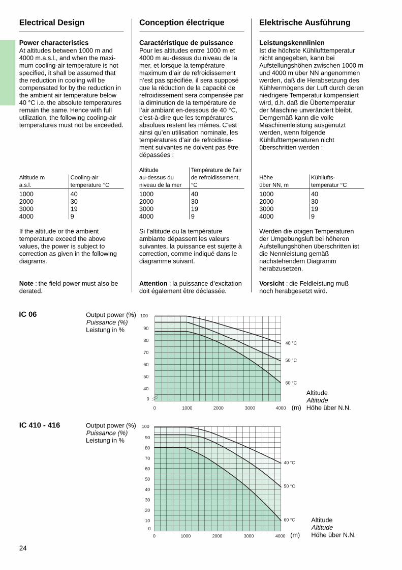
Power characteristicsAt altitudes between 1000 m and4000 m.a.s.l., and when the maxi-mum cooling-air temperature is notspecified, it shall be assumed thatthe reduction in cooling will becompensated for by the reduction inthe ambient air temperature below40 °C i.e. the absolute temperaturesremain the same. Hence with fullutilization, the following cooling-airtemperatures must not be exceeded.
Altitude m Cooling-aira.s.l. temperature °C1000 402000 303000 194000 9
If the altitude or the ambienttemperature exceed the abovevalues, the power is subject tocorrection as given in the followingdiagrams.
Note : the field power must also bederated.
Conception électrique
Caractéristique de puissancePour les altitudes entre 1000 m et4000 m au-dessus du niveau de lamer, et lorsque la températuremaximum d’air de refroidissementn’est pas spécifiée, il sera supposéque la réduction de la capacité derefroidissement sera compensée parla diminution de la température del’air ambiant en-dessous de 40 °C,c’est-à-dire que les températuresabsolues restent les mêmes. C’estainsi qu’en utilisation nominale, lestempératures d’air de refroidisse-ment suivantes ne doivent pas êtredépassées :
Altitude Température de l’airau-dessus du de refroidissement,niveau de la mer °C1000 402000 303000 194000 9
Si l’altitude ou la températureambiante dépassent les valeurssuivantes, la puissance est sujette àcorrection, comme indiqué dans lediagramme suivant.
Attention : la puissance d’excitationdoit également être déclassée.
Elektrische Ausführung
LeistungskennlinienIst die höchste Kühllufttemperaturnicht angegeben, kann beiAufstellungshöhen zwischen 1000 mund 4000 m über NN angenommenwerden, daß die Herabsetzung desKühlvermögens der Luft durch derenniedrigere Temperatur kompensiertwird, d.h. daß die Übertemperaturder Maschine unverändert bleibt.Demgemäß kann die volleMaschinenleistung ausgenutztwerden, wenn folgendeKühllufttemperaturen nichtüberschritten werden :
Höhe Kühllufts-über NN, m temperatur °C1000 402000 303000 194000 9
Werden die obigen Temperaturender Umgebungsluft bei höherenAufstellungshöhen überschritten istdie Nennleistung gemäßnachstehendem Diagrammherabzusetzen.
Vorsicht : die Feldleistung mußnoch herabgesetzt wird.
100
90
80
70
60
50
40
30
20
10
0
0 1000 2000 3000 4000
60 °C
50 °C
40 °C
IC 06
IC 410 - 416
(m)
AltitudeAltitudeHöhe über N.N.(m)
Output power (%)Puissance (%)Leistung in %
25
Electrical Design
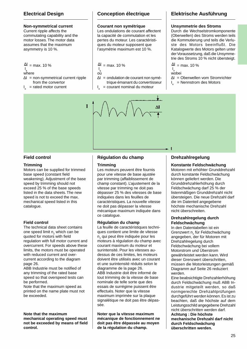
Non-symmetrical currentCurrent ripple affects thecommutating capability and themotor losses. The motor dataassumes that the maximumasymmetry is 10 %.
∆I = max. 10 %Ia
where∆I = non-symmetrical current ripple
from the convertorIa
= rated motor current
Field control
TrimmingMotors can be supplied for trimmedbase speed (constant fieldweakening). Adjustment of the basespeed by trimming should notexceed 25 % of the base speedslisted in the data sheets. The newspeed is not to exceed the max.mechanical speed listed in thiscatalogue.
Field controlThe technical data sheet containsone speed limit n2 which can bequoted for motors with fieldregulation with full motor current andovercurrent. For speeds above theselimits, the motors must be operatedwith reduced current and over-current according to the diagrampage 26.ABB Industrie must be notified ofany trimming of the rated basespeed so that overspeed tests canbe performed.Note that the maximum speed asprinted on the name plate must notbe exceeded.
Note that the maximummechanical operating speed mustnot be exceeded by means of fieldcontrol.
Conception électrique
Courant non symétriqueLes ondulations de courant affectentla capacité de commutation et lespertes du moteur. Les caractéristi-ques du moteur supposent quel’asymétrie maximum est 10 %.
∆I = max. 10 %Ia
où∆I = ondulation de courant non symé-
trique émanant du convertisseurIa
= courant nominal du moteur
Régulation du champ
TrimmingLes moteurs peuvent être fournispour une vitesse de base ajustéepar trimming (affaiblissement dechamp constant). L’ajustement de lavitesse par trimming ne doit pasdépasser 25 % des vitesses de baseindiquées dans les feuilles decaractéristiques. La nouvelle vitessene doit pas dépasser la vitessemécanique maximum indiquée dansce catalogue.
Régulation du champLa feuille de caractéristiques techni-ques contient une limite de vitessen2 qui peut être indiquée pour lesmoteurs à régulation du champ aveccourant maximum du moteur etsurintensité. Pour les vitesses au-dessus de ces limites, les moteursdoivent être utilisés avec un courantet une surintensité réduits selon lediagramme de la page 26.ABB Industrie doit être informé detout trimming de la vitesse de basenominale de telle sorte que desessais de surrégime puissent êtreeffectués. Noter que la vitessemaximum imprimée sur la plaquesignalétique ne doit pas être dépas-sée.
Noter que la vitesse maximummécanique de fonctionnement nedoit pas être dépassée au moyende la régulation du champ.
Elektrische Ausführung
Unsymmetrie des StromsDurch die Wechselstromkomponente(Oberwellen) des Stroms werden teilsdie Kommutierung und teils die Verlu-ste des Motors beeinflußt. DieKatalogwerte des Motors gelten unterder Voraussetzung, daß die Unsymme-trie des Stroms 10 % nicht übersteigt.
∆I = max. 10 %Ia
wobei∆I = Oberwellen vom StromrichterIa = Nennstrom des Motors
Drehzahlregelung
Konstante FeldschwächungMotoren mit erhöhter Grunddrehzahldurch konstante Feldschwächungkönnen geliefert werden. DieGrunddrehzahlerhöhung durchFeldschwächung darf 25 % derlistenmäßigen Grunddrehzahl nichtübersteigen. Die neue Drehzahl darfdie im Datenteil angegebenehöchste mechanische Drehzahlnicht überschreiten.
Drehzahlregelung durchFeldschwächungIn den Datentabellen ist einGrenzwert n
2 für Feldschwächung
angegeben, der für Motoren mitDrehzahlregelung durchFeldschwächung bei vollemMotorstrom und Überstromgewährleistet werden kann. Wirddieser Grenzwert überschritten,müssen die Motorleistungen gemäßDiagramm auf Seite 26 reduziertwerden.Eine beabsichtigte Drehzahlerhöhungdurch Feldschwächung muß ABB In-dustrie mitgeteilt werden, so daßnormgerechte Drehzahlprüfungendurchgeführt werden können. Es ist zubeachten, daß die höchste auf demLeistungsschild angegebene Drehzahlnicht überschritten werden darf.Achtung : Die höchstemechanische Drehzahl darf nichtdurch Feldschwächungüberschritten werden.
26
Electrical Design
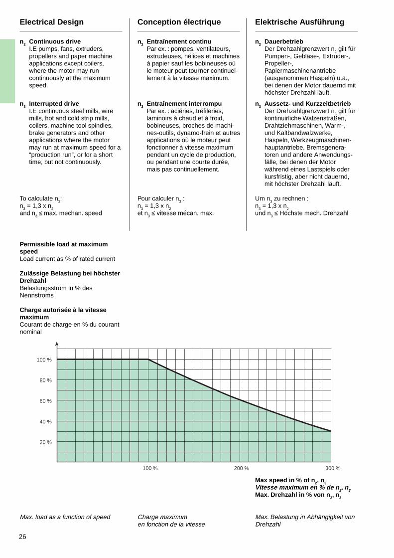
n2 Continuous driveI.E pumps, fans, extruders,propellers and paper machineapplications except coilers,where the motor may runcontinuously at the maximumspeed.
n3 Interrupted driveI.E continuous steel mills, wiremills, hot and cold strip mills,coilers, machine tool spindles,brake generators and otherapplications where the motormay run at maximum speed for a“production run”, or for a shorttime, but not continuously.
To calculate n3:n
3 = 1,3 x n
2and n3 ≤ max. mechan. speed
Max. load as a function of speed
Conception électrique
n2 Entraînement continuPar ex. : pompes, ventilateurs,extrudeuses, hélices et machinesà papier sauf les bobineuses oùle moteur peut tourner continuel-lement à la vitesse maximum.
n3 Entraînement interrompuPar ex. : aciéries, tréfileries,laminoirs à chaud et à froid,bobineuses, broches de machi-nes-outils, dynamo-frein et autresapplications où le moteur peutfonctionner à vitesse maximumpendant un cycle de production,ou pendant une courte durée,mais pas continuellement.
Pour calculer n3 :n
3 = 1,3 x n
2et n3 ≤ vitesse mécan. max.
Charge maximumen fonction de la vitesse
Elektrische Ausführung
n2 DauerbetriebDer Drehzahlgrenzwert n
2 gilt für
Pumpen-, Gebläse-, Extruder-,Propeller-,Papiermaschinenantriebe(ausgenommen Haspeln) u.ä.,bei denen der Motor dauernd mithöchster Drehzahl läuft.
n3 Aussetz- und KurzzeitbetriebDer Drehzahlgrenzwert n3 gilt fürkontinuirliche Walzenstraßen,Drahtziehmaschinen, Warm-,und Kaltbandwalzwerke,Haspeln, Werkzeugmaschinen-hauptantriebe, Bremsgenera-toren und andere Anwendungs-fälle, bei denen der Motorwährend eines Lastspiels oderkursfristig, aber nicht dauernd,mit höchster Drehzahl läuft.
Um n3 zu rechnen :n
3 = 1,3 x n
2und n3 ≤ Höchste mech. Drehzahl
Max. Belastung in Abhängigkeit vonDrehzahl
Permissible load at maximumspeedLoad current as % of rated current
Zulässige Belastung bei höchsterDrehzahlBelastungsstrom in % desNennstroms
Charge autorisée à la vitessemaximumCourant de charge en % du courantnominal
Max speed in % of n 2, n3Vitesse maximum en % de n 2, n3Max. Drehzahl in % von n 2, n3
100 %
80 %
60 %
40 %
20 %
100 % 200 % 300 %
27
Accessories
General
Reliable operation begins with thecorrect choice of “degree of protec-tion” (IP) and “method of cooling”(IC), in relation to the operationalenvironment, and the correct choiceof protective accessories.
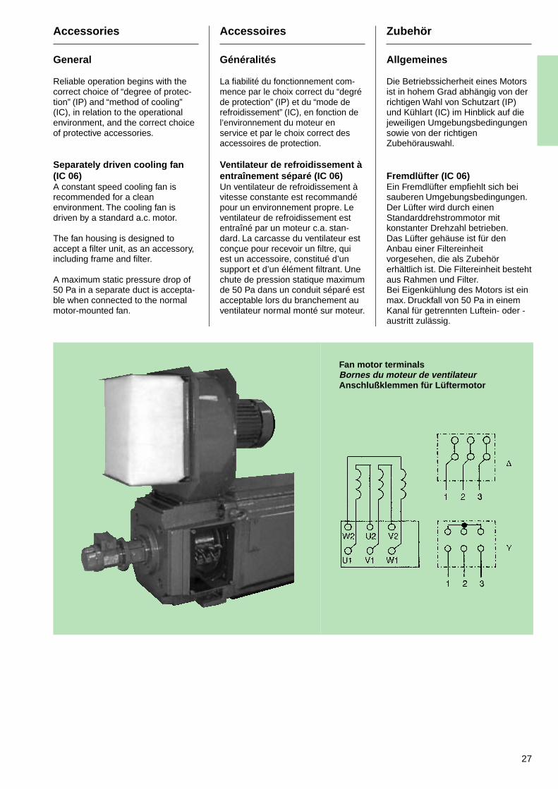
Separately driven cooling fan(IC 06)A constant speed cooling fan isrecommended for a cleanenvironment. The cooling fan isdriven by a standard a.c. motor.
The fan housing is designed toaccept a filter unit, as an accessory,including frame and filter.
A maximum static pressure drop of50 Pa in a separate duct is accepta-ble when connected to the normalmotor-mounted fan.
Accessoires
Généralités
La fiabilité du fonctionnement com-mence par le choix correct du “degréde protection” (IP) et du “mode derefroidissement” (IC), en fonction del’environnement du moteur enservice et par le choix correct desaccessoires de protection.
Ventilateur de refroidissement àentraînement séparé (IC 06)Un ventilateur de refroidissement àvitesse constante est recommandépour un environnement propre. Leventilateur de refroidissement estentraîné par un moteur c.a. stan-dard. La carcasse du ventilateur estconçue pour recevoir un filtre, quiest un accessoire, constitué d’unsupport et d’un élément filtrant. Unechute de pression statique maximumde 50 Pa dans un conduit séparé estacceptable lors du branchement auventilateur normal monté sur moteur.
Zubehör
Allgemeines
Die Betriebssicherheit eines Motorsist in hohem Grad abhängig von derrichtigen Wahl von Schutzart (IP)und Kühlart (IC) im Hinblick auf diejeweiligen Umgebungsbedingungensowie von der richtigenZubehörauswahl.
Fremdlüfter (IC 06)Ein Fremdlüfter empfiehlt sich beisauberen Umgebungsbedingungen.Der Lüfter wird durch einenStandarddrehstrommotor mitkonstanter Drehzahl betrieben.Das Lüfter gehäuse ist für denAnbau einer Filtereinheitvorgesehen, die als Zubehörerhältlich ist. Die Filtereinheit bestehtaus Rahmen und Filter.Bei Eigenkühlung des Motors ist einmax. Druckfall von 50 Pa in einemKanal für getrennten Luftein- oder -austritt zulässig.
Fan motor terminalsBornes du moteur de ventilateurAnschlußklemmen für Lüftermotor
28
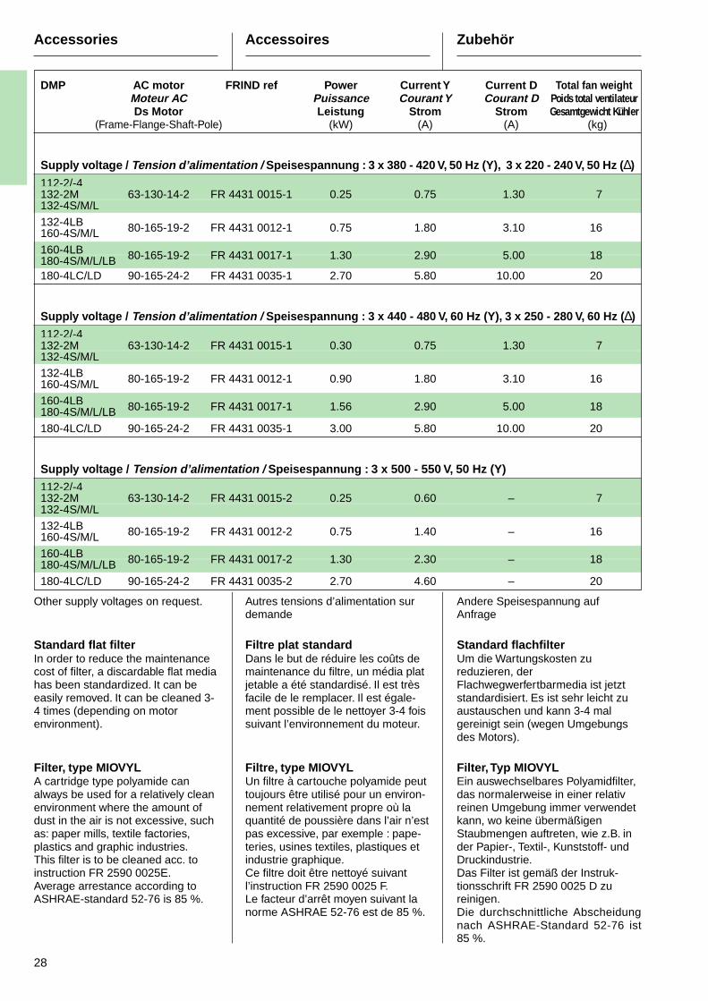
DMP AC motor FRIND ref Power Current Y Current D Total fan weightMoteur AC Puissance Courant Y Courant D Poids total ventilateurDs Motor Leistung Strom Strom Gesamtgewicht Kühler
(Frame-Flange-Shaft-Pole) (kW) (A) (A) (kg)
Supply voltage / Tension d’alimentation / Speisespannung : 3 x 380 - 420 V, 50 Hz (Y), 3 x 220 - 240 V, 50 Hz ( ∆)
112-2/-4132-2M 63-130-14-2 FR 4431 0015-1 0.25 0.75 1.30 7132-4S/M/L
132-4LB 80-165-19-2 FR 4431 0012-1 0.75 1.80 3.10 16160-4S/M/L
160-4LB180-4S/M/L/LB 80-165-19-2 FR 4431 0017-1 1.30 2.90 5.00 18
180-4LC/LD 90-165-24-2 FR 4431 0035-1 2.70 5.80 10.00 20
Supply voltage / Tension d’alimentation / Speisespannung : 3 x 440 - 480 V, 60 Hz (Y), 3 x 250 - 280 V, 60 Hz ( ∆)112-2/-4132-2M 63-130-14-2 FR 4431 0015-1 0.30 0.75 1.30 7132-4S/M/L132-4LB 80-165-19-2 FR 4431 0012-1 0.90 1.80 3.10 16160-4S/M/L
160-4LB180-4S/M/L/LB 80-165-19-2 FR 4431 0017-1 1.56 2.90 5.00 18
180-4LC/LD 90-165-24-2 FR 4431 0035-1 3.00 5.80 10.00 20
Supply voltage / Tension d’alimentation / Speisespannung : 3 x 500 - 550 V, 50 Hz (Y)112-2/-4132-2M 63-130-14-2 FR 4431 0015-2 0.25 0.60 – 7132-4S/M/L132-4LB 80-165-19-2 FR 4431 0012-2 0.75 1.40 – 16160-4S/M/L
160-4LB180-4S/M/L/LB 80-165-19-2 FR 4431 0017-2 1.30 2.30 – 18
180-4LC/LD 90-165-24-2 FR 4431 0035-2 2.70 4.60 – 20
Accessories Accessoires Zubehör
Other supply voltages on request.
Standard flat filterIn order to reduce the maintenancecost of filter, a discardable flat mediahas been standardized. It can beeasily removed. It can be cleaned 3-4 times (depending on motorenvironment).
Filter, type MIOVYLA cartridge type polyamide canalways be used for a relatively cleanenvironment where the amount ofdust in the air is not excessive, suchas: paper mills, textile factories,plastics and graphic industries.This filter is to be cleaned acc. toinstruction FR 2590 0025E.Average arrestance according toASHRAE-standard 52-76 is 85 %.
Autres tensions d’alimentation surdemande
Filtre plat standardDans le but de réduire les coûts demaintenance du filtre, un média platjetable a été standardisé. Il est trèsfacile de le remplacer. Il est égale-ment possible de le nettoyer 3-4 foissuivant l’environnement du moteur.
Filtre, type MIOVYLUn filtre à cartouche polyamide peuttoujours être utilisé pour un environ-nement relativement propre où laquantité de poussière dans l’air n’estpas excessive, par exemple : pape-teries, usines textiles, plastiques etindustrie graphique.Ce filtre doit être nettoyé suivantl’instruction FR 2590 0025 F.Le facteur d’arrêt moyen suivant lanorme ASHRAE 52-76 est de 85 %.
Andere Speisespannung aufAnfrage
Standard flachfilterUm die Wartungskosten zureduzieren, derFlachwegwerfertbarmedia ist jetztstandardisiert. Es ist sehr leicht zuaustauschen und kann 3-4 malgereinigt sein (wegen Umgebungsdes Motors).
Filter, Typ MIOVYLEin auswechselbares Polyamidfilter,das normalerweise in einer relativreinen Umgebung immer verwendetkann, wo keine übermäßigenStaubmengen auftreten, wie z.B. inder Papier-, Textil-, Kunststoff- undDruckindustrie.Das Filter ist gemäß der Instruk-tionsschrift FR 2590 0025 D zureinigen.Die durchschnittliche Abscheidungnach ASHRAE-Standard 52-76 ist85 %.
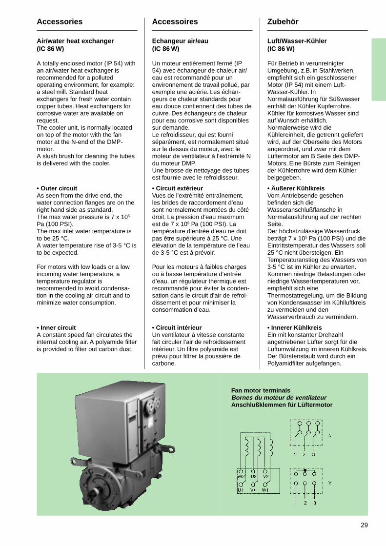
29
Accessories
Air/water heat exchanger(IC 86 W)
A totally enclosed motor (IP 54) withan air/water heat exchanger isrecommended for a pollutedoperating environment, for example:a steel mill. Standard heatexchangers for fresh water containcopper tubes. Heat exchangers forcorrosive water are available onrequest.The cooler unit, is normally locatedon top of the motor with the fanmotor at the N-end of the DMP-motor.A slush brush for cleaning the tubesis delivered with the cooler.
• Outer circuitAs seen from the drive end, thewater connection flanges are on theright hand side as standard.The max water pressure is 7 x 10⁵
Pa (100 PSI).The max inlet water temperature isto be 25 °C.A water temperature rise of 3-5 °C isto be expected.
For motors with low loads or a lowincoming water temperature, atemperature regulator isrecommended to avoid condensa-tion in the cooling air circuit and tominimize water consumption.
• Inner circuitA constant speed fan circulates theinternal cooling air. A polyamide filteris provided to filter out carbon dust.
Accessoires
Echangeur air/eau(IC 86 W)
Un moteur entièrement fermé (IP54) avec échangeur de chaleur air/eau est recommandé pour unenvironnement de travail pollué, parexemple une aciérie. Les échan-geurs de chaleur standards poureau douce contiennent des tubes decuivre. Des échangeurs de chaleurpour eau corrosive sont disponiblessur demande.Le refroidisseur, qui est fourniséparément, est normalement situésur le dessus du moteur, avec lemoteur de ventilateur à l’extrémité Ndu moteur DMP.Une brosse de nettoyage des tubesest fournie avec le refroidisseur.
• Circuit extérieurVues de l’extrémité entraînement,les brides de raccordement d’eausont normalement montées du côtédroit. La pression d’eau maximumest de 7 x 10⁵ Pa (100 PSI). Latempérature d’entrée d’eau ne doitpas être supérieure à 25 °C. Uneélévation de la température de l’eaude 3-5 °C est à prévoir.
Pour les moteurs à faibles chargesou à basse température d’entréed’eau, un régulateur thermique estrecommandé pour éviter la conden-sation dans le circuit d’air de refroi-dissement et pour minimiser laconsommation d’eau.
• Circuit intérieurUn ventilateur à vitesse constantefait circuler l’air de refroidissementintérieur. Un filtre polyamide estprévu pour filtrer la poussière decarbone.
Zubehör
Luft/Wasser-Kühler(IC 86 W)
Für Betrieb in verunreinigterUmgebung, z.B. in Stahlwerken,empfiehlt sich ein geschlossenerMotor (IP 54) mit einem Luft-Wasser-Kühler. InNormalausführung für Süßwasserenthält der Kühler Kupferrohre.Kühler für korrosives Wasser sindauf Wunsch erhältlich.Normalerweise wird dieKühlereinheit, die getrennt geliefertwird, auf der Oberseite des Motorsangeordnet, und zwar mit demLüftermotor am B Seite des DMP-Motors. Eine Bürste zum Reinigender Kühlerrohre wird dem Kühlerbeigegeben.
• Äußerer KühlkreisVom Antriebsende gesehenbefinden sich dieWasseranschlußflansche inNormalausführung auf der rechtenSeite.Der höchstzulässige Wasserdruckbeträgt 7 x 10⁵ Pa (100 PSI) und dieEintrittstemperatur des Wassers soll25 °C nicht übersteigen. EinTemperaturanstieg des Wassers von3-5 °C ist im Kühler zu erwarten.Kommen niedrige Belastungen oderniedrige Wassertemperaturen vor,empfiehlt sich eineThermostatregelung, um die Bildungvon Kondenswasser im Kühlluftkreiszu vermeiden und denWasserverbrauch zu vermindern.
• Innerer KühlkreisEin mit konstanter Drehzahlangetriebener Lüfter sorgt für dieLuftumwälzung im inneren Kühlkreis.Der Bürstenstaub wird durch einPolyamidfilter aufgefangen.
Fan motor terminalsBornes du moteur de ventilateurAnschlußklemmen für Lüftermotor
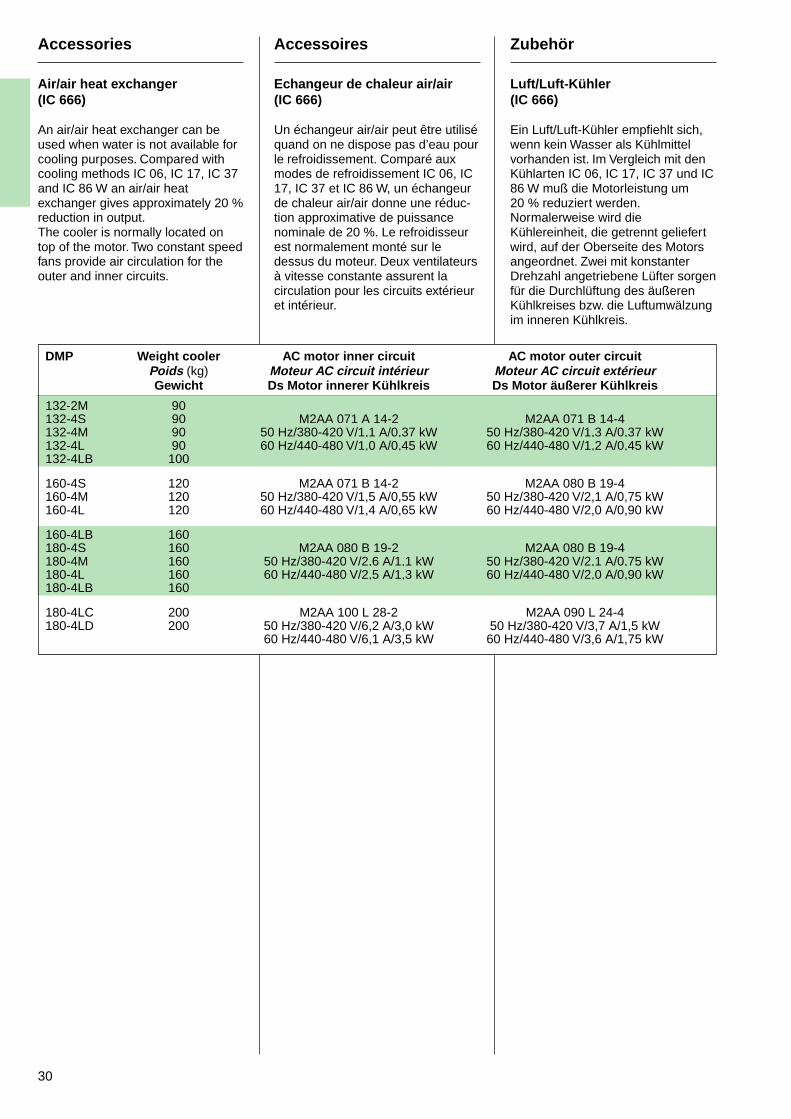
30
Accessories
Air/air heat exchanger(IC 666)
An air/air heat exchanger can beused when water is not available forcooling purposes. Compared withcooling methods IC 06, IC 17, IC 37and IC 86 W an air/air heatexchanger gives approximately 20 %reduction in output.The cooler is normally located ontop of the motor. Two constant speedfans provide air circulation for theouter and inner circuits.
Accessoires
Echangeur de chaleur air/air(IC 666)
Un échangeur air/air peut être utiliséquand on ne dispose pas d’eau pourle refroidissement. Comparé auxmodes de refroidissement IC 06, IC17, IC 37 et IC 86 W, un échangeurde chaleur air/air donne une réduc-tion approximative de puissancenominale de 20 %. Le refroidisseurest normalement monté sur ledessus du moteur. Deux ventilateursà vitesse constante assurent lacirculation pour les circuits extérieuret intérieur.
Zubehör
Luft/Luft-Kühler(IC 666)
Ein Luft/Luft-Kühler empfiehlt sich,wenn kein Wasser als Kühlmittelvorhanden ist. Im Vergleich mit denKühlarten IC 06, IC 17, IC 37 und IC86 W muß die Motorleistung um20 % reduziert werden.Normalerweise wird dieKühlereinheit, die getrennt geliefertwird, auf der Oberseite des Motorsangeordnet. Zwei mit konstanterDrehzahl angetriebene Lüfter sorgenfür die Durchlüftung des äußerenKühlkreises bzw. die Luftumwälzungim inneren Kühlkreis.
DMP Weight cooler AC motor inner circuit AC motor outer circuitPoids (kg) Moteur AC circuit intérieur Moteur AC circuit extérieurGewicht Ds Motor innerer Kühlkreis Ds Motor äußerer Kühlkreis
132-2M 90132-4S 90 M2AA 071 A 14-2 M2AA 071 B 14-4132-4M 90 50 Hz/380-420 V/1,1 A/0,37 kW 50 Hz/380-420 V/1,3 A/0,37 kW132-4L 90 60 Hz/440-480 V/1,0 A/0,45 kW 60 Hz/440-480 V/1,2 A/0,45 kW132-4LB 100
160-4S 120 M2AA 071 B 14-2 M2AA 080 B 19-4160-4M 120 50 Hz/380-420 V/1,5 A/0,55 kW 50 Hz/380-420 V/2,1 A/0,75 kW160-4L 120 60 Hz/440-480 V/1,4 A/0,65 kW 60 Hz/440-480 V/2,0 A/0,90 kW
160-4LB 160180-4S 160 M2AA 080 B 19-2 M2AA 080 B 19-4180-4M 160 50 Hz/380-420 V/2,6 A/1,1 kW 50 Hz/380-420 V/2,1 A/0,75 kW180-4L 160 60 Hz/440-480 V/2,5 A/1,3 kW 60 Hz/440-480 V/2,0 A/0,90 kW180-4LB 160
180-4LC 200 M2AA 100 L 28-2 M2AA 090 L 24-4180-4LD 200 50 Hz/380-420 V/6,2 A/3,0 kW 50 Hz/380-420 V/3,7 A/1,5 kW
60 Hz/440-480 V/6,1 A/3,5 kW 60 Hz/440-480 V/3,6 A/1,75 kW
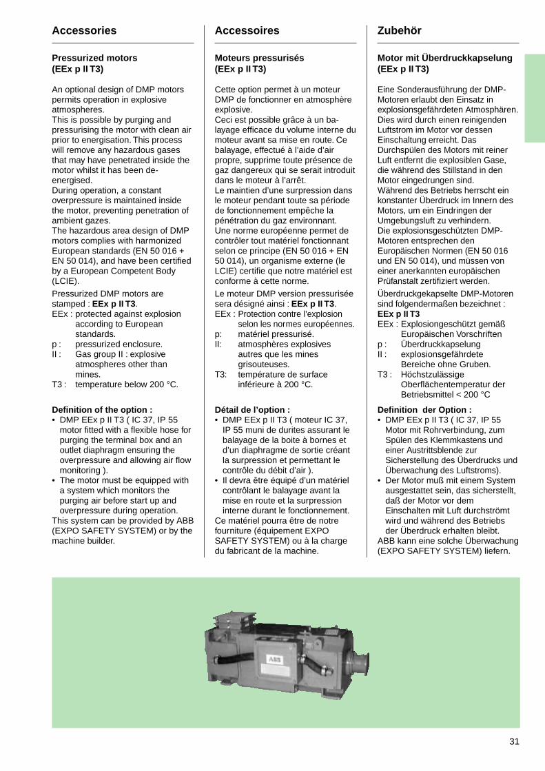
31
Accessories
Pressurized motors(EEx p II T3)
An optional design of DMP motorspermits operation in explosiveatmospheres.This is possible by purging andpressurising the motor with clean airprior to energisation. This processwill remove any hazardous gasesthat may have penetrated inside themotor whilst it has been de-energised.During operation, a constantoverpressure is maintained insidethe motor, preventing penetration ofambient gazes.The hazardous area design of DMPmotors complies with harmonizedEuropean standards (EN 50 016 +EN 50 014), and have been certifiedby a European Competent Body(LCIE).
Pressurized DMP motors arestamped : EEx p II T3 .EEx : protected against explosion
according to Europeanstandards.
p : pressurized enclosure.II : Gas group II : explosive
atmospheres other thanmines.
T3 : temperature below 200 °C.
Definition of the option :• DMP EEx p II T3 ( IC 37, IP 55
motor fitted with a flexible hose forpurging the terminal box and anoutlet diaphragm ensuring theoverpressure and allowing air flowmonitoring ).
• The motor must be equipped witha system which monitors thepurging air before start up andoverpressure during operation.
This system can be provided by ABB(EXPO SAFETY SYSTEM) or by themachine builder.
Accessoires
Moteurs pressurisés(EEx p II T3)
Cette option permet à un moteurDMP de fonctionner en atmosphèreexplosive.Ceci est possible grâce à un ba-layage efficace du volume interne dumoteur avant sa mise en route. Cebalayage, effectué à l’aide d’airpropre, supprime toute présence degaz dangereux qui se serait introduitdans le moteur à l’arrêt.Le maintien d’une surpression dansle moteur pendant toute sa périodede fonctionnement empêche lapénétration du gaz environnant.Une norme européenne permet decontrôler tout matériel fonctionnantselon ce principe (EN 50 016 + EN50 014), un organisme externe (leLCIE) certifie que notre matériel estconforme à cette norme.
Le moteur DMP version pressuriséesera désigné ainsi : EEx p II T3 .EEx : Protection contre l’explosion
selon les normes européennes.p: matériel pressurisé.II: atmosphères explosives
autres que les minesgrisouteuses.
T3: température de surfaceinférieure à 200 °C.
Détail de l’option :• DMP EEx p II T3 ( moteur IC 37,
IP 55 muni de durites assurant lebalayage de la boite à bornes etd’un diaphragme de sortie créantla surpression et permettant lecontrôle du débit d’air ).
• Il devra être équipé d’un matérielcontrôlant le balayage avant lamise en route et la surpressioninterne durant le fonctionnement.
Ce matériel pourra être de notrefourniture (équipement EXPOSAFETY SYSTEM) ou à la chargedu fabricant de la machine.
Zubehör
Motor mit Überdruckkapselung(EEx p II T3)
Eine Sonderausführung der DMP-Motoren erlaubt den Einsatz inexplosionsgefährdeten Atmosphären.Dies wird durch einen reinigendenLuftstrom im Motor vor dessenEinschaltung erreicht. DasDurchspülen des Motors mit reinerLuft entfernt die explosiblen Gase,die während des Stillstand in denMotor eingedrungen sind.Während des Betriebs herrscht einkonstanter Überdruck im Innern desMotors, um ein Eindringen derUmgebungsluft zu verhindern.Die explosionsgeschützten DMP-Motoren entsprechen denEuropäischen Normen (EN 50 016und EN 50 014), und müssen voneiner anerkannten europäischenPrüfanstalt zertifiziert werden.
Überdruckgekapselte DMP-Motorensind folgendermaßen bezeichnet :EEx p II T3EEx : Explosiongeschützt gemäß
Europäischen Vorschriftenp : ÜberdruckkapselungII : explosionsgefährdete
Bereiche ohne Gruben.T3 : Höchstzulässige
Oberflächentemperatur derBetriebsmittel < 200 °C
Definition der Option :• DMP EEx p II T3 ( IC 37, IP 55
Motor mit Rohrverbindung, zumSpülen des Klemmkastens undeiner Austrittsblende zurSicherstellung des Überdrucks undÜberwachung des Luftstroms).
• Der Motor muß mit einem Systemausgestattet sein, das sicherstellt,daß der Motor vor demEinschalten mit Luft durchströmtwird und während des Betriebsder Überdruck erhalten bleibt.
ABB kann eine solche Überwachung(EXPO SAFETY SYSTEM) liefern.
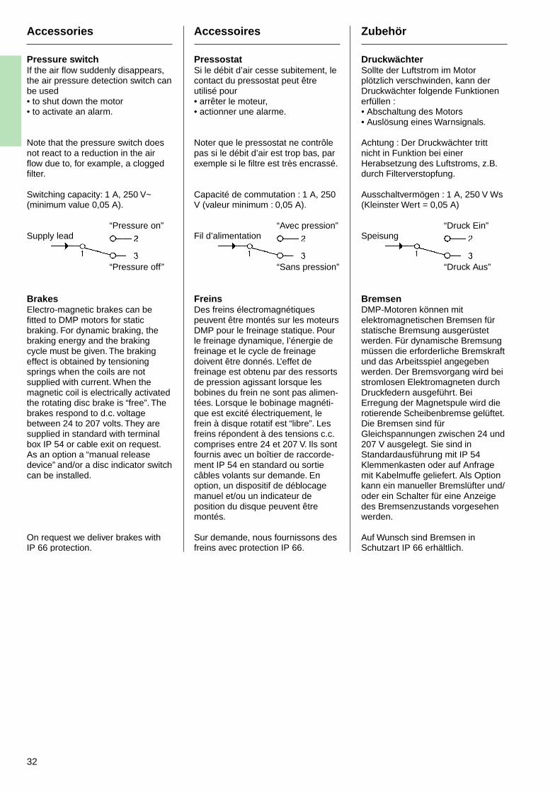
32
Accessories
Pressure switchIf the air flow suddenly disappears,the air pressure detection switch canbe used• to shut down the motor• to activate an alarm.
Note that the pressure switch doesnot react to a reduction in the airflow due to, for example, a cloggedfilter.
Switching capacity: 1 A, 250 V~(minimum value 0,05 A).
“Pressure on”Supply lead
“Pressure off”
BrakesElectro-magnetic brakes can befitted to DMP motors for staticbraking. For dynamic braking, thebraking energy and the brakingcycle must be given. The brakingeffect is obtained by tensioningsprings when the coils are notsupplied with current. When themagnetic coil is electrically activatedthe rotating disc brake is “free”. Thebrakes respond to d.c. voltagebetween 24 to 207 volts. They aresupplied in standard with terminalbox IP 54 or cable exit on request.As an option a “manual releasedevice” and/or a disc indicator switchcan be installed.
On request we deliver brakes withIP 66 protection.
Accessoires
PressostatSi le débit d’air cesse subitement, lecontact du pressostat peut êtreutilisé pour• arrêter le moteur,• actionner une alarme.
Noter que le pressostat ne contrôlepas si le débit d’air est trop bas, parexemple si le filtre est très encrassé.
Capacité de commutation : 1 A, 250V (valeur minimum : 0,05 A).
“Avec pression”Fil d’alimentation
“Sans pression”
FreinsDes freins électromagnétiquespeuvent être montés sur les moteursDMP pour le freinage statique. Pourle freinage dynamique, l’énergie defreinage et le cycle de freinagedoivent être donnés. L’effet defreinage est obtenu par des ressortsde pression agissant lorsque lesbobines du frein ne sont pas alimen-tées. Lorsque le bobinage magnéti-que est excité électriquement, lefrein à disque rotatif est “libre”. Lesfreins répondent à des tensions c.c.comprises entre 24 et 207 V. Ils sontfournis avec un boîtier de raccorde-ment IP 54 en standard ou sortiecâbles volants sur demande. Enoption, un dispositif de déblocagemanuel et/ou un indicateur deposition du disque peuvent êtremontés.
Sur demande, nous fournissons desfreins avec protection IP 66.
Zubehör
DruckwächterSollte der Luftstrom im Motorplötzlich verschwinden, kann derDruckwächter folgende Funktionenerfüllen :• Abschaltung des Motors• Auslösung eines Warnsignals.
Achtung : Der Druckwächter trittnicht in Funktion bei einerHerabsetzung des Luftstroms, z.B.durch Filterverstopfung.
Ausschaltvermögen : 1 A, 250 V Ws(Kleinster Wert = 0,05 A)
“Druck Ein”Speisung
“Druck Aus”
BremsenDMP-Motoren können mitelektromagnetischen Bremsen fürstatische Bremsung ausgerüstetwerden. Für dynamische Bremsungmüssen die erforderliche Bremskraftund das Arbeitsspiel angegebenwerden. Der Bremsvorgang wird beistromlosen Elektromagneten durchDruckfedern ausgeführt. BeiErregung der Magnetspule wird dierotierende Scheibenbremse gelüftet.Die Bremsen sind fürGleichspannungen zwischen 24 und207 V ausgelegt. Sie sind inStandardausführung mit IP 54Klemmenkasten oder auf Anfragemit Kabelmuffe geliefert. Als Optionkann ein manueller Bremslüfter und/oder ein Schalter für eine Anzeigedes Bremsenzustands vorgesehenwerden.
Auf Wunsch sind Bremsen inSchutzart IP 66 erhältlich.
33
Accessories
Temperature sensorsFor protection against thermaloverload, temperature sensors canbe installed, on request, in theinterpole and field windings. Thetemperature sensors do notguarantee complete protection ofother windings, due to differentthermal time constants. The rotormust always be protected by ther-mal-delay overcurrent trippingdevices.With thermostat temperaturesensors (bimetal type) a contact isactivated when the temperature ofthe motor winding exceeds themaximum permissible operatingvalue.Maximum rated current is 10 A atcos ϕ = 1 or 6,3 A at cos ϕ = 0,6.Maximum breaking capacity is 25 Aat 250 V~.In temperature sensors of thermistortype a high value of resistance isobtained when the motor windingtemperature exceeds the maximumpermissible operating value. Theresistance at 25 °C is max. 250ohms.
Bearing sensorThe bearing sensor is a preventivemaintenance device to monitorminor bearing defects.Measurements by this method atregular intervals provide an effectivesupervision of bearing conditions asbearing faults can be detected early.This reduces the risk of unexpectedbearing failure and allows plannedbearing replacements.The device is a steel plug, located inthe end shield, which transmitsshock pulses to a receiver. Asuitable shock pulse receiver can beobtained from
SPM Instruments ABBox 4
SE 64521 STRÄNGNÄSSWEDEN
Fax : +46(0) 152 15075
Earthing brushA grounding brush can be installedto prevent current passing throughthe bearings which might otherwisecause bearing damage, particularlyto small bearings in accessories.
Accessoires
Sondes de températurePour la protection contre les sur-charges thermiques, des sondes detempérature peuvent être montées,sur demande, dans les enroule-ments de pôle de commutation et dechamp. Les sondes de températurene garantissent pas une protectioncomplète des autres enroulements,du fait des importantes constantesde temps thermiques, le rotor doittoujours être protégé par desdispositifs de déclenchement parsurintensité avec délai thermique.Dans les sondes de température detype bilame, un contact est actionnéquand la température de l’enroule-ment de moteur dépasse la valeurde service maximum autorisée.Le courant nominal maximum est 10A à cos ϕ = 1 ou 6,3 A à cos ϕ = 0,6.Le pouvoir de coupure est 25 A à250 V.Dans les sondes de température detype thermistor, une haute valeur derésistance est obtenue quand latempérature de l’enroulement dumoteur dépasse la valeur de servicemaximum autorisée. La résistance à25 °C est 250 Ω maximum.
Capteur de roulementLe capteur de palier est un dispositifd’entretien préventif prévu pourcontrôler les défauts mineurs desroulements. Les mesures effectuéespar cette méthode à intervallesréguliers assurent un contrôleefficace de l’état des paliers enpermettant de détecter suffisammenttôt les défauts des roulements. Celaréduit le risque de défaillanceimprévue d’un palier et permet deprévoir à l’avance le remplacementdes roulements. Le dispositif est uncapteur en acier situé sur le gardegraisse, qui transmet les impulsionsde chocs à un récepteur. Un récep-teur d’impulsions de chocs appropriépeut être obtenu auprès de
SPM Instruments ABBox 4
SE 64521 STRÄNGNÄSSWEDEN
Fax : +46(0) 152 15075
Balai de mise à la terreUn balai de mise à la terre peut êtreinstallé pour empêcher le courant detraverser les roulements, ce quipourrait endommager les roule-ments, surtout les petits roulementsdans les accessoires.
Zubehör
TemperaturfühlerZum Schutz vor thermischerÜberlastung können auf WunschTemperaturfühler in Wendepol- undFeldwicklungen eingebaut werden.Diese gewährleisten aufgrundunterschiedlicher thermischerZeitkonstanten keinen vollständigenSchutz für andere Wicklungen. DerMotor muß stets durch thermischverzögerte überstromauslösergeschützt werden.Durch Temperaturfühler desBimetalltyps wird ein Schalterausgelöst, wenn die höchstzulässigeTemperatur der Motorwicklungüberschritten wird.Max. Nennstrom ist 10 A bei cos ϕ =1,0 oder 6,3 A bei cos ϕ = 0,6. DerSchalter hat ein max.Abschaltvermögen von 25 A bei250 V Ws.Temperaturfühler desThermistortyps nehmen einenhohen Widerstandswert an, wenndie höchstzulässigeBetriebstemperatur derMotorwicklung überschritten wird.Der Widerstand bei 25 °C beträgtmax. 250 Ω.
LagerwächterDer Lagerwächter ist ein Hilfsmittelzur Vorbeugung von Lagerschäden.Er ermöglicht eine wirksameÜberwachung des Lagerzustandsdurch regelmäßige Messungen undeine frühzeitige Endeckung vongeringeren Lagerfehlern. Hierdurchwird das Risiko unerwarteterLagerschäden verringert und dieEinplanung von Lageraustauschmöglich gemacht. BeimLagerwächter handelt es sich umeinen Stahlnippel, der imLagerschild angeordnet ist undStoßimpulse in einen geeignetenEmpfänger überträgt. Ein passendesInstrument ist erhältlich von derFirma
SPM Instruments ABBox 4
SE 64521 STRÄNGNÄSSWEDEN
Fax : +46(0) 152 15075
ErdungsbürsteEine Erdungsbürste kannvorgesehen werden, umStromdurchgang durch Lager zuverhindern, wodurch sonst,besonders in kleinen Lagern vonZubehörausrüstungen,Lagerschäden verursacht werdenkönnen.
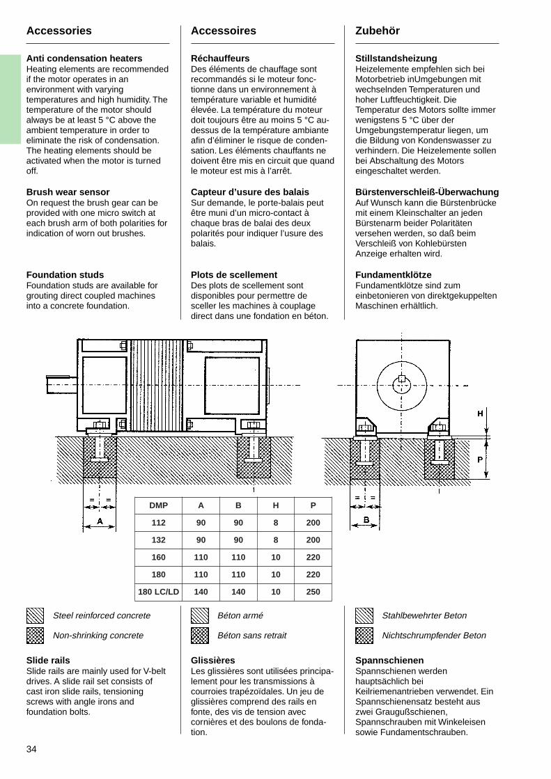
34
Accessories
Anti condensation heatersHeating elements are recommendedif the motor operates in anenvironment with varyingtemperatures and high humidity. Thetemperature of the motor shouldalways be at least 5 °C above theambient temperature in order toeliminate the risk of condensation.The heating elements should beactivated when the motor is turnedoff.
Brush wear sensorOn request the brush gear can beprovided with one micro switch ateach brush arm of both polarities forindication of worn out brushes.
Foundation studsFoundation studs are available forgrouting direct coupled machinesinto a concrete foundation.
Steel reinforced concrete
Non-shrinking concrete
Slide railsSlide rails are mainly used for V-beltdrives. A slide rail set consists ofcast iron slide rails, tensioningscrews with angle irons andfoundation bolts.
Accessoires
RéchauffeursDes éléments de chauffage sontrecommandés si le moteur fonc-tionne dans un environnement àtempérature variable et humiditéélevée. La température du moteurdoit toujours être au moins 5 °C au-dessus de la température ambianteafin d’éliminer le risque de conden-sation. Les éléments chauffants nedoivent être mis en circuit que quandle moteur est mis à l’arrêt.
Capteur d’usure des balaisSur demande, le porte-balais peutêtre muni d’un micro-contact àchaque bras de balai des deuxpolarités pour indiquer l’usure desbalais.
Plots de scellementDes plots de scellement sontdisponibles pour permettre desceller les machines à couplagedirect dans une fondation en béton.
Béton armé
Béton sans retrait
GlissièresLes glissières sont utilisées principa-lement pour les transmissions àcourroies trapézoïdales. Un jeu deglissières comprend des rails enfonte, des vis de tension aveccornières et des boulons de fonda-tion.
Zubehör
StillstandsheizungHeizelemente empfehlen sich beiMotorbetrieb inUmgebungen mitwechselnden Temperaturen undhoher Luftfeuchtigkeit. DieTemperatur des Motors sollte immerwenigstens 5 °C über derUmgebungstemperatur liegen, umdie Bildung von Kondenswasser zuverhindern. Die Heizelemente sollenbei Abschaltung des Motorseingeschaltet werden.
Bürstenverschleiß-ÜberwachungAuf Wunsch kann die Bürstenbrückemit einem Kleinschalter an jedenBürstenarm beider Polaritätenversehen werden, so daß beimVerschleiß von KohlebürstenAnzeige erhalten wird.
FundamentklötzeFundamentklötze sind zumeinbetonieren von direktgekuppeltenMaschinen erhältlich.
Stahlbewehrter Beton
Nichtschrumpfender Beton
SpannschienenSpannschienen werdenhauptsächlich beiKeilriemenantrieben verwendet. EinSpannschienensatz besteht auszwei Graugußschienen,Spannschrauben mit Winkeleisensowie Fundamentschrauben.
PMD A B H P
211 09 09 8 002
231 09 09 8 002
061 011 011 01 022
081 011 011 01 022
DL/CL081 041 041 01 052
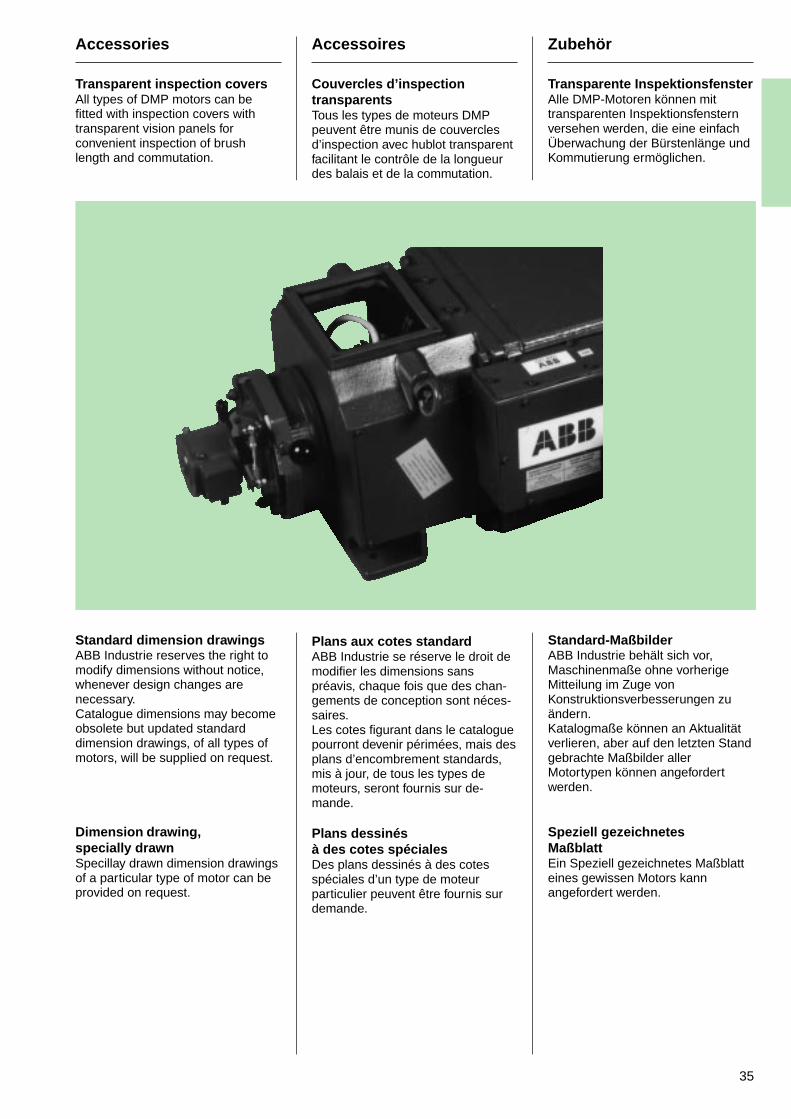
35
Accessories
Transparent inspection coversAll types of DMP motors can befitted with inspection covers withtransparent vision panels forconvenient inspection of brushlength and commutation.
Standard dimension drawingsABB Industrie reserves the right tomodify dimensions without notice,whenever design changes arenecessary.Catalogue dimensions may becomeobsolete but updated standarddimension drawings, of all types ofmotors, will be supplied on request.
Dimension drawing,specially drawnSpecillay drawn dimension drawingsof a particular type of motor can beprovided on request.
Accessoires
Couvercles d’inspectiontransparentsTous les types de moteurs DMPpeuvent être munis de couverclesd’inspection avec hublot transparentfacilitant le contrôle de la longueurdes balais et de la commutation.
Plans aux cotes standardABB Industrie se réserve le droit demodifier les dimensions sanspréavis, chaque fois que des chan-gements de conception sont néces-saires.Les cotes figurant dans le cataloguepourront devenir périmées, mais desplans d’encombrement standards,mis à jour, de tous les types demoteurs, seront fournis sur de-mande.
Plans dessinésà des cotes spécialesDes plans dessinés à des cotesspéciales d’un type de moteurparticulier peuvent être fournis surdemande.
Zubehör
Transparente InspektionsfensterAlle DMP-Motoren können mittransparenten Inspektionsfensternversehen werden, die eine einfachÜberwachung der Bürstenlänge undKommutierung ermöglichen.
Standard-MaßbilderABB Industrie behält sich vor,Maschinenmaße ohne vorherigeMitteilung im Zuge vonKonstruktionsverbesserungen zuändern.Katalogmaße können an Aktualitätverlieren, aber auf den letzten Standgebrachte Maßbilder allerMotortypen können angefordertwerden.
Speziell gezeichnetesMaßblattEin Speziell gezeichnetes Maßblatteines gewissen Motors kannangefordert werden.
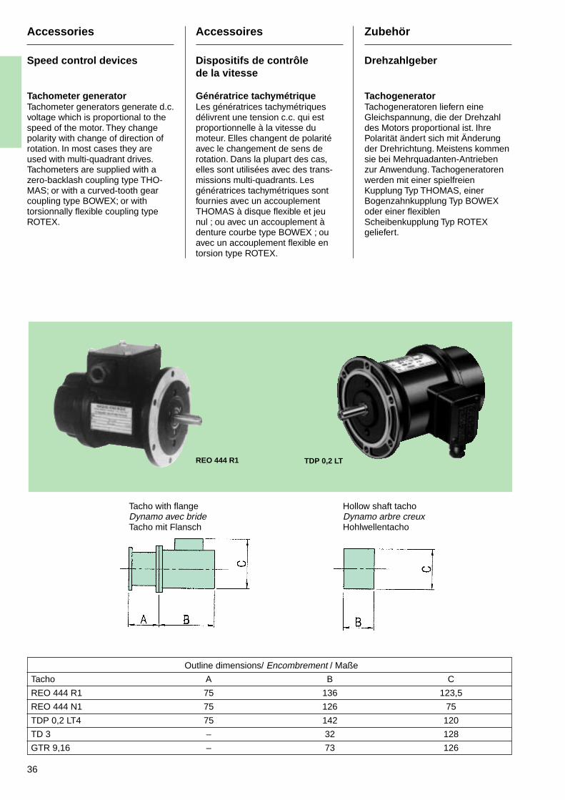
36
Accessories
Speed control devices
Tachometer generatorTachometer generators generate d.c.voltage which is proportional to thespeed of the motor. They changepolarity with change of direction ofrotation. In most cases they areused with multi-quadrant drives.Tachometers are supplied with azero-backlash coupling type THO-MAS; or with a curved-tooth gearcoupling type BOWEX; or withtorsionnally flexible coupling typeROTEX.
Accessoires
Dispositifs de contrôlede la vitesse
Génératrice tachymétriqueLes génératrices tachymétriquesdélivrent une tension c.c. qui estproportionnelle à la vitesse dumoteur. Elles changent de polaritéavec le changement de sens derotation. Dans la plupart des cas,elles sont utilisées avec des trans-missions multi-quadrants. Lesgénératrices tachymétriques sontfournies avec un accouplementTHOMAS à disque flexible et jeunul ; ou avec un accouplement àdenture courbe type BOWEX ; ouavec un accouplement flexible entorsion type ROTEX.
Zubehör
Drehzahlgeber
TachogeneratorTachogeneratoren liefern eineGleichspannung, die der Drehzahldes Motors proportional ist. IhrePolarität ändert sich mit Änderungder Drehrichtung. Meistens kommensie bei Mehrquadanten-Antriebenzur Anwendung. Tachogeneratorenwerden mit einer spielfreienKupplung Typ THOMAS, einerBogenzahnkupplung Typ BOWEXoder einer flexiblenScheibenkupplung Typ ROTEXgeliefert.
REO 444 R1 TDP 0,2 LT
Outline dimensions/ Encombrement / Maße
Tacho A B C
REO 444 R1 75 136 123,5
REO 444 N1 75 126 75
TDP 0,2 LT4 75 142 120
TD 3 – 32 128
GTR 9,16 – 73 126
Tacho with flangeDynamo avec brideTacho mit Flansch
Hollow shaft tachoDynamo arbre creuxHohlwellentacho
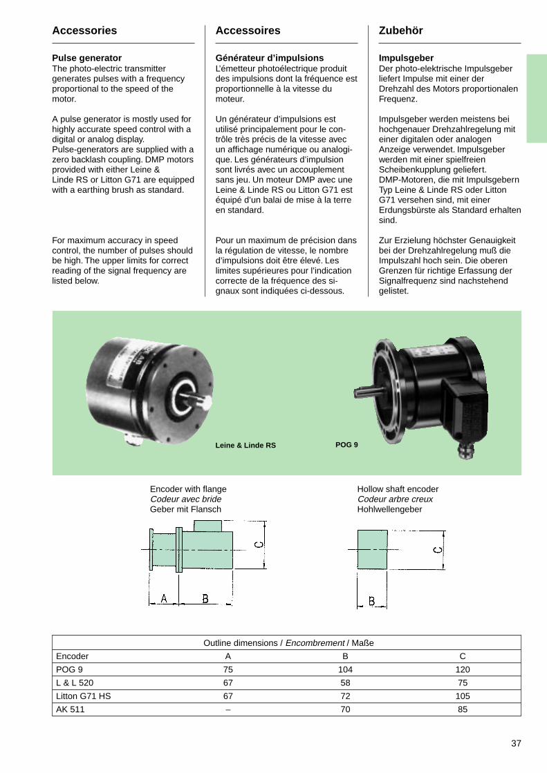
37
Accessories
Pulse generatorThe photo-electric transmittergenerates pulses with a frequencyproportional to the speed of themotor.
A pulse generator is mostly used forhighly accurate speed control with adigital or analog display.Pulse-generators are supplied with azero backlash coupling. DMP motorsprovided with either Leine &Linde RS or Litton G71 are equippedwith a earthing brush as standard.
For maximum accuracy in speedcontrol, the number of pulses shouldbe high. The upper limits for correctreading of the signal frequency arelisted below.
Accessoires
Générateur d’impulsionsL’émetteur photoélectrique produitdes impulsions dont la fréquence estproportionnelle à la vitesse dumoteur.
Un générateur d’impulsions estutilisé principalement pour le con-trôle très précis de la vitesse avecun affichage numérique ou analogi-que. Les générateurs d’impulsionsont livrés avec un accouplementsans jeu. Un moteur DMP avec uneLeine & Linde RS ou Litton G71 estéquipé d’un balai de mise à la terreen standard.
Pour un maximum de précision dansla régulation de vitesse, le nombred’impulsions doit être élevé. Leslimites supérieures pour l’indicationcorrecte de la fréquence des si-gnaux sont indiquées ci-dessous.
Zubehör
ImpulsgeberDer photo-elektrische Impulsgeberliefert Impulse mit einer derDrehzahl des Motors proportionalenFrequenz.
Impulsgeber werden meistens beihochgenauer Drehzahlregelung miteiner digitalen oder analogenAnzeige verwendet. Impulsgeberwerden mit einer spielfreienScheibenkupplung geliefert.DMP-Motoren, die mit ImpulsgebernTyp Leine & Linde RS oder LittonG71 versehen sind, mit einerErdungsbürste als Standard erhaltensind.
Zur Erzielung höchster Genauigkeitbei der Drehzahlregelung muß dieImpulszahl hoch sein. Die oberenGrenzen für richtige Erfassung derSignalfrequenz sind nachstehendgelistet.
POG 9Leine & Linde RS
Outline dimensions / Encombrement / Maße
Encoder A B C
POG 9 75 104 120
L & L 520 67 58 75
Litton G71 HS 67 72 105
AK 511 – 70 85
Encoder with flangeCodeur avec brideGeber mit Flansch
Hollow shaft encoderCodeur arbre creuxHohlwellengeber
38
Accessories
Safety devices
The following equipment isrecommended for the protection ofthe DMP motor:
A. In the power supply unit.
• Thermal-delay overcurrent trip(100 % of Ia).
• Instantaneous overcurrent trip(200 % of Ia).
• Ground fault trip (wet or dirtywindings).
• Overvoltage limiters (max 1000 Vsurge voltage in the fieldwinding).
• Overspeed protection (forexample minimum field current).
B. In the motor
• Temperature sensor(temperature sensor is essentialwith air/air and air/water heatexchangers).
• Heating element.
• Earthing brush.
• Bearing sensor.
C. Accessories
• Speed control device.
• Air filter.
• Pressure switch.
D. Equipment not deliveredby ABB Industrie
• Differential pressure switch(clogged air filter).
• Vibration measurement forbearing sensors.
Accessoires
Dispositifs de sécurité
Les équipements suivants sontrecommandés pour la protection desmoteurs DMP :
A. Dans le module d’alimentation
• Déclenchement par surintensitéavec délai thermique (100 % de Ia)
• Déclenchement instantané parsurintensité (200 % de Ia)
• Déclenchement par défaut à laterre (enroulements humides ouencrassés)
• Limiteurs de surtension (pointede tension de 1000 V maximumdans l’enroulement de champ)
• Protection contre les survitesses(par exemple courant de champminimum)
B. Dans le moteur
• Sonde de température (unesonde de température estessentielle avec les échangeursair/air et air/eau)
• Elément chauffant
• Balai de mise à la terre
• Capteur de roulement
C. Accessoires
• Dispositif de contrôle de lavitesse
• Filtre à air
• Pressostat
D. Equipement non livrépar ABB Industrie
• Contacteur de pression différen-tielle (filtre à air colmaté)
• Récepteur de vibrations pourcapteur de roulement
Zubehör
Schutzeinrichtungen
Folgende Schutzeinrichtungenempfehlen sich für DMP-Motoren:
A. In der Stromversorgungseinheit
• Thermisch verzögerte Überstro-mauslösung (100 % von Ia).
• UnverzögerteÜberstromauslösung (200 % vonIa).
• Erdschlußauslösung (nasse oderschmutzige Wicklungen).
• Überspannungsschutz (max.1000 V) Stoßspannung in derFeldwicklung).
• Schleuderschutz (z.B. min.Erregerstrom).
B. Im Motor :
• Temperaturfühler(Temperaturfühler sind wichtig,wenn Luft/Luft- und Luft/Wasser-Wärmetauscher vorgesehensind).
• Heizelement.
• Erdungsbürste.
• Lagerwächter.
C. Zubehör :
• Drehzahlgeber.
• Luftfilter.
• Druckwächter.
D. Nicht von ABB Industriegelieferte Ausrüstung
• Differentialdruckschalter(verstopftes Luftfilter).
• Schwingungssensoren.
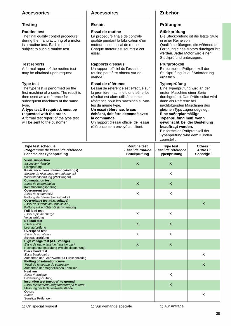
39
Accessories
Testing
Routine testThe final quality control procedureduring the manufacturing of a motoris a routine test. Each motor issubject to such a routine test.
Test reportsA formal report of the routine testmay be obtained upon request.
Type testThe type test is performed on thefirst machine of a serie. The result isthen used as a reference forsubsequent machines of the sametype.A type test, if required, must berequested with the order.A formal test report of the type testwill be sent to the customer.
Accessoires
Essais
Essai de routineLa procédure finale de contrôlequalité pendant la fabrication d’unmoteur est un essai de routine.Chaque moteur est soumis à cetessai.
Rapports d’essaisUn rapport officiel de l’essai deroutine peut être obtenu sur de-mande.
Essai de référenceL’essai de référence est effectué surla première machine d’une série. Lerésultat est alors utilisé commeréférence pour les machines suivan-tes du même type.Un essai référence, le caséchéant, doit être demandé avecla commande.Un rapport d’essai officiel de l’essairéférence sera envoyé au client.
Zubehör
Prüfungen
StückprüfungDie Stückprüfung ist die letzte Stufein einer Reihe vonQualitätsprüfungen, die während derFertigung eines Motors durchgeführtwerden. Jeder Motor wird einerStückprüfund unterzogen.
PrüfprotokollEin formelles Prüfprotokoll derStückprüfung ist auf Anforderungerhältlich.
TypenprüfungEine Typenprüfung wird an derersten Maschine einer Seriedurchgeführt. Das Prüfresultat wirddann als Referenz beinachfolgenden Maschinen desgleichen Typs zugrundegelegt.Eine außerplanmäßigeTypenprüfung muß, wenngewünscht, bei der Bestellungbeauftragt werden.Ein formelles Prüfprotokoll derTypenprüfung wird dem Kundenzugestellt.
Type test schedule Routine test Type test Others 1)
Programme de l’essai de référence Essai de routine Essai de référence Autres 1)
Schema der Typenprüfung Stückprüfung Typenprüfung Sonstige 1)
Visual inspectionInspection visuelle X XSichtprüfungResistance measurement (windings)Mesure de résistance (enroulements) XWiderstandsprüfung (Wicklungen)Commutation testEssai de commutation X XKommutierungsprüfungOvercurrent testEssai de surintensité X XPrüfung der StromüberlastbarkeitOvervoltage test (d.c. voltage)Essai de surtension (tension c.c.) XPrüfung mit erhöhter GleichspannungFull-load testEssai à pleine charge X XVollastprüfungNo-load testEssai à vide X XLeerlaufprüfungOverspeed testEssai de survitesse X XSchleuderprüfungHigh voltage test (A.C. voltage)Essai de haute tension (tension c.a.) X XHochspannungsprüfung (Wechselspannung)Black band testEssai bande noire XAufnahme der Grenzwerte für FunkenbildungPlotting of saturation curveTracé de la courbe de saturation XAufnahme der magnetischen KennlinieHeat runEssai thermique XErwärmungsprüfungInsulation test (megger) to groundEssai d’isolement (mégohmmètre) à la terre XMessung der IsolationswiderständeOthersAutres XSonstige Prüfungen
1) On special request 1) Sur demande spéciale 1) Auf Anfrage
40
Tables and Diagrams
Explanatory notesThe tables and diagrams enable theselection of a suitable motor for agiven requirement, and also give themost important technical data.
Where speed control is to beeffected by field-weakening, the typeshould always be determined interms of required output at the basicspeed (nb), i.e. the speed at full fieldstrength and full armature voltage(operating voltage). The maximumoperating speed must not exceedthe specified maximum mechanicalspeed for the motor type selected.Power, voltage, current and speedfigures which differ from those in thetable can be calculatedproportionally up to a maximumdifference of ± 20 %. The powershould never be increased whenspeed is increased by field-weakening. If field-weakeningexceeds n
2, the power should be
reduced in accordance with thereduction curve (page 26): ifnecessary, a larger motor should beselected.The following examples illustrate theprocedure for selecting a motor.
Tableaux et diagrammes
Notes explicativesLes tableaux et diagrammes permet-tent la sélection d’un moteur appro-prié pour une situation donnée, etdonnent aussi les caractéristiquestechniques les plus importantes.
Lorsque la régulation de vitesse doitêtre assurée par désexcitation, letype doit toujours être déterminé parla puissance requise à la vitesse debase (nb), c’est-à-dire la vitesse àplein champ et à la tension d’induitmaximum (tension de fonctionne-ment). La vitesse maximum defonctionnement ne doit pas dépas-ser la vitesse mécanique maximumpour le type de moteur sélectionné.Les valeurs de puissance, detension, de courant et de vitesse quidiffèrent de ceux du tableau peuventêtre calculées proportionnellementjusqu’à une différence maximum de± 20 %. La puissance ne doit jamaisêtre augmentée lorsque la vitesseest accrue par affaiblissement duchamp. Si l’affaiblissement duchamp dépasse n2, la puissance doitêtre réduite conformément à lacourbe de réduction (page 26) : sinécessaire, un plus gros moteurdevra être choisi.Les exemples suivants illustrent lamarche à suivre pour sélectionnerun moteur.
Tabellen und Diagramme
ErläuterungenDie Tabellen und Diagrammeermöglichen die Auswahl einesgeeigneten Motors für einengegebenen Anwendungsfall undenthalten auch die wichtigstentechnischen Daten.
Soll die Drehzahl durchFeldschwächung gesteuert werden,ist der Typenauswahl stets dieerforderliche Leistung bei derGrunddrehzahl (nb), d.h. derDrehzahl mit voller Feldstärke undvoller Ankerspannung(Betriebsspannung), zugrunde zulegen. Die Höchste Betriebsdrehzahldarf die spezifizierte höchstemechanische Drehzahl desgewählten Motortyps nichtüberschreiten.Leistung-, Spannungs-, Strom- undDrehzahlwerte, die von denTabellenwerten abweichen, könnenbis zu ± 20 % interpoliert werden.Die Leistung darf unter keinenUmständen erhöht werden, wenndie Drehzahl durch Feldschwächungerhöht wird Überschreite dieFeldschwächung n
2, muß die
Leistung gemäß derReduktionskennlinie (Seite 26) :herabgesetzt werden, underforderlichenfalls muß ein größererMotor gewählt werden.Die nachstehenden Beispieleveranschaulichen das Verfahren beider Motorauswahl.
41
Tables and Diagrams
Calculation examples
Example 1:Motor with separate ventilation, nofield-weakening
RequirementsMotor power 50 kWSpeed 1350 rpmArmature voltage 470 VFan ventilated, IC 06
The exact characteristic data for thismotor are found in the data sheet onpage 79. Here we see that the datafor DMP 180 4-M FR 148201 GC is57,5 kW, 1190 rpm 460 V, 142 A.
The speed can be matched to therequired speed of 1350 r/min byreducing the ampere-turns bytrimming.The required armature voltage is470 V instead of the listed 460 V,therefore the actual rated speed andoutput will be:
P = 57,5 kW 470 V = 58,75 kW460 V
n = 1190 rpm 470 V = 1215 rpm460 V
It must then be checked that therequired speed increase to 1350rpm is within the 25 % limit; if so, thesame output can be delivered aswould have been delivered at ratedexcitation.Trimming :
[ 1350 rpm – 1] x 100 = ~11 %1215 rpm
Due to the trimming, the outputremains constant, so that only50 kW is required instead of58,75 kW, and the rated current is:
I = 142 A x 50 kW = ≈ 121 A58,57 kW
The final data for the required d.c.motor, type DMP 180 4-M FR158201 GC is therefore as follows:
Power 50 kWSpeed 1350 rpmVoltage 470 VCurrent 121 A
Tableaux et diagrammes
Exemples de calcul
Exemple 1 :Moteur avec ventilation séparée,sans désexcitation
Exigences :Puissance moteur 50 kWVitesse 1350 tr/minTension d’induit 470 VRefroidissement par ventilateur, IC 06
Les caractéristiques exactes de cemoteur se trouvent sur la fichetechnique de la page 79. Nousvoyons que les caractéristiques duDMP 180 4-M FR 158201 GC sont57,5 kW, 1190 tr/mn, 460 V, 142 A.
On peut amener la vitesse à lavaleur requise de 1350 tr/mn enréduisant le courant d’excitation(ampères-tours) par trimming.La tension d’induit requise est 470 Vau lieu de 460 V. La puissance et lavitesse nominales réelles serontdonc :
P = 57,5 kW 470 V = 58,75 kW460 V
n = 1190 tr/min 470 V = 1215 tr/min460 V
Il faut vérifier que l’augmentation dela vitesse jusqu’à 1350 tr/mn estdans la limite de 25 % ; dansl’affirmative, la puissance délivréesera la même que celle qui auraitété délivrée à l’excitation nominale.Trimming :
[ 1350 tr/min – 1] x 100 = ~11 %1215 tr/min
Du fait du trimming, la puissancereste constante, si bien que seule-ment 50 kW sont nécessaires aulieu de 58,75 kW, et le courantnominal est :
I = 142 A x 50 kW = ≈ 121 A58,57 kW
Les caractéristiques finales pour lemoteur c.c. requis, type DMP 180 4-M, FR 158 201 GC sont donc lessuivantes :
Puissance 50 kWVitesse 1350 tr/minTension 470 VCourant 121 A
Tabellen und Diagramme
Berechnungsbeispiele
Beispiel 1 :Motor mit Fremdkühlung, keineFeldschwächung
Anforderungen :Motorleistung 50 kWDrehzahl 1350 upmAnkerspannung 470 VFremdlüfter, IC 06
Die genauen technischen Daten fürdiesen Motor finden sich auf Seite79. Hier sind für DMP 180 4-M, FR158 201 GC folgende Datenangegeben : 57,5 kW, 1190 upm,460 V, 142 A.
Die Drehzahl kann auf denerforderlichen Wert von 1350 upmdurch Verminderung derAmperewindungen (kontinuierlicheFeldschwächung) erhöht werden.Die erforderliche Ankerspannungbeträgt 470 V anstelle der gelisteten460 V, weshalb folgendetatsächliche Werte für Leistung undDrehzahl erhalten werden :
P = 57,5 kW 470 V = 58,75 kW460 V
n = 1190 upm 470 V = 1215 upm460 V
Es muß kontrolliert werden, ob die25 %-Grenze bei der erforderlichenDrehzahlerhöhung auf 1350 upmeingehalten wird. Ist die der Fall, kanndieselbe Leistung wie bei Nennerre-gerleistung abgegeben werden.Feldschwächung :
[ 1350 upm – 1] x 100 = ~11 %1215 upm
Gemäß der Feldschwächungs-Prozentzahl bleibt die Leistungunverändert. Es sind also nur 50 kWanstelle von 58,75 kW erforderlich,was folgendem Stromwert entspricht :
I = 142 A x 50 kW = ≈ 121 A58,57 kW
Der gewünschte GleichstrommotorTyp DMP 180 4-M, FR 158 201 GCerhält daher folgende endgültigeDaten :
Leistung 50 kWDrehzahl 1350 upmSpannung 470 VStrom 121 A
42
Tables and Diagrams
Calculation examples
Example 2:Motor operating with field-weakening, separate ventilationThe correct size of motor for a givenapplication is determined basicallyby the following procedure:
1. Select a preliminary motor typeand armature circuit for the base(lower) speed.
2. Determine the allowed power forthe motor under field-weakeningconditions, from the relevantpower reduction curve, thencheck to establish whether thepermissible power for theselected motor type is sufficient.If not, repeat steps 1 and 2 forthe next larger motor size.
Requirements:Motor power 40 40 kWSpeed 1015 1900 rpmArmature voltage 400 400 VIC 17
The selection chart and voltage/speed characteristics indicate a typeDMP 180 4-M FR 158 201 GC motorfor the 1015 rpm base speedcondition. From the data sheet onpage 79 the characteristic data forthis motor is:
49,2 kW, 1015 rpm, 400 V, 142 A,n2 = 1520 rpm.
The power reduction factor k forfield-weakening operation is found inthe corresponding curve on page 26.
k =0,89 (maximum field-weakeningspeed n
max = 1900 rpm).
Hence the allowable power at 1900rpm is:
P = 0,89 x 49,2 = 43,8 kW
and
I = 142 A x 40 kW = 115,5 A49,2 kW
The following is the final data for therequired motor:Power 40 40 kWSpeed 1015 1900 rpmVoltage 400 400 VCurrent 115,5 115,5 A
Tableaux et diagrammes
Exemples de calcul
Exemple 2 :Moteur fonctionnant avec désexcita-tion et ventilation séparée. La taillecorrecte du moteur pour une appli-cation donnée est déterminéefondamentalement par la procéduresuivante :
1. Choisir un type de moteur et uncircuit d’induit préliminaires pourla vitesse de base (inférieure).
2. Déterminer la puissance autori-sée pour le moteur dans lesconditions d’affaiblissement duchamp, à partir de la courbe deréduction de puissance appro-priée, puis vérifier si la puissanceautorisée pour le type de moteurest suffisante. Dans la négative,répéter les opérations 1 et 2 pourle moteur de la taille immédiate-ment supérieure.
Exigences :Puissance du moteur 40 40 kWVitesse 1015 1900 tr/minTension d’induit 400 400 VIC 17
Le tableau de sélection et lescaractéristiques tension/vitessemontrent un moteur de type DMP180 4-M FR 158 201 GC pour lavitesse de base de 1015 tr/min. Lafiche technique de la page 79 donneles caractéristiques suivantes pource moteur :49,2 kW, 1015 tr/min, 400 V, 142 A,n2 = 1520 tr/min.
Le facteur de réduction de puissancek pour l’opération d’affaiblissementdu champ se trouve dans la courbecorrespondante à la page 26.
k =0,89 (vitesse maximum d’affai-blissement du champnmax = 1900 tr/min
Ainsi, la puissance disponible à1900 tr/min est :
P = 0,89 x 49,2 = 43,8 kW
et
I = 142 A x 40 kW = 115,5 A49,2 kW
Les caractéristiques finales pour lemoteur requis sont les suivantes :Puissance 40 40 kWVitesse 1015 1900 tr/minTension 400 400 VCourant 115,5 115,5 A
Tabellen und Diagramme
Berechnungsbeispiele
Beispiel 2 :Motor mit drehzahlsteuerung durchFeldschwächung, getrennt belüftet.Die geeignete Größe des Motors füreinen gegebenen Anwendungsfallwird durch folgendes Verfahrengenerell bestimmt :
1. Vorläufige Auswahl einesMotortyps und Ankerkreises fürdie Grunddrehzahl (dieniedrigere Drehzahl).
2. Bestimmung der zulässigenMotorleistung beiFeldschwächung mit Hilfe dereinschlägigen Leistungs-reduktions-Kennlinie undanschließende Kontrolle, ob diezulässige Leistung für dengewählten Motor ausreicht. Istdies nicht der Fall, sind diePunkte 1 und 2 für dennächstgrößeren Motor zuwiederholen.
Anforderungen :Motorleistung 40 40 kWDrehzahl 1015 1900 upmAnkerspannung 400 400 VIC 17
Das Auswahldiagramm und dieSpannung/Drehzahlkennliniengeben Hinweis auf einen Motor TypDMP 180 4-M, FR 158 201 GC füreine Grunddrehzahl von 1015 upm.Gemäß Seite 79 hat dieser Motorfolgende Daten :
49,2 kW, 1015 upm, 400 V, 142 A,n2 = 1520 upm.
Der Leistungsreduktionsfaktor k fürden Feldschwächungsbetrieb istdem Diagramm auf Seite 26 zuentnhmen :
k =0,89 (max. Drehzahl beiFeldswächung nmax =1900 upm.
Demnach beträgt die zulässigeLeistung bei 1900 upm :
P = 0,89 x 49,2 = 43,8 kW
und
I = 142 A x 40 kW = 115,5 A49,2 kW
Der gewünschte Motor erhältfolgende endgültige Daten :Leistung 40 40 kWDrehzahl 1015 1900 upmSpannung 400 400 VStrom 115,5 115,5 A
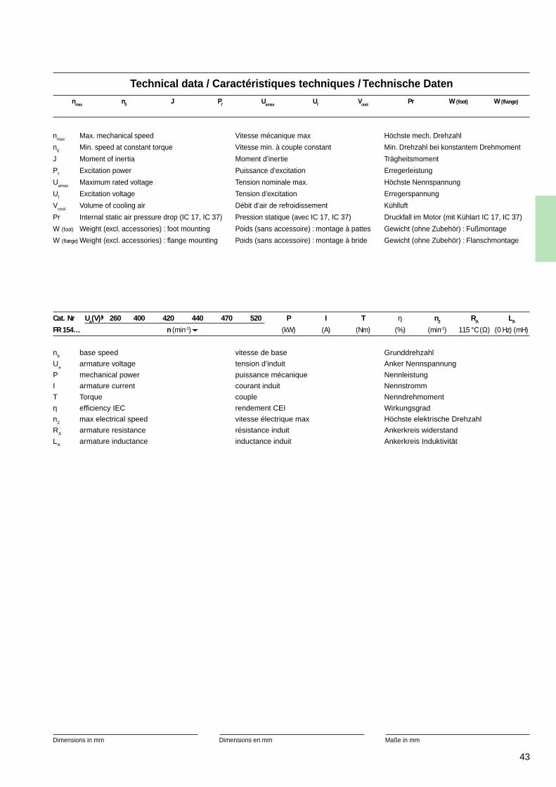
43
1 Cooling air inlet at commutator side. Can be usedwith cooling air inlet at shaft side with 10 % reductionof the power.
* Normally kept in stock with tropicalisation.See page 156.
1 Arrivée d’air de refroidissement côté collecteur. Peutêtre utilisé avec l’entrée d’air côté bout d’arbremoyennant une réduction de puissance de 10 %.
* Normalement en stock et tropicalisés.Voir page 156.
1 Kühllufteingang an Kommutatorseite. Kann auchdurch Leistungsverminderung von 10 % mitLufteintritt auf Antriebseite Verwendet werden.
* Normal auf Lager und tropenfest.Siehe Seite 156.
Technical data / Caractéristiques techniques / Technische Datennmax n0 J Pf Uamax Uf Vcool Pr W (foot) W (flange)
nmax Max. mechanical speed Vitesse mécanique max Höchste mech. Drehzahl
n0
Min. speed at constant torque Vitesse min. à couple constant Min. Drehzahl bei konstantem Drehmoment
J Moment of inertia Moment d’inertie Trägheitsmoment
Pf Excitation power Puissance d’excitation Erregerleistung
Uamax Maximum rated voltage Tension nominale max. Höchste Nennspannung
Uf
Excitation voltage Tension d’excitation Erregerspannung
Vcool Volume of cooling air Débit d’air de refroidissement Kühlluft
Pr Internal static air pressure drop (IC 17, IC 37) Pression statique (avec IC 17, IC 37) Druckfall im Motor (mit Kühlart IC 17, IC 37)
W (foot) Weight (excl. accessories) : foot mounting Poids (sans accessoire) : montage à pattes Gewicht (ohne Zubehör) : Fußmontage
W (flange) Weight (excl. accessories) : flange mounting Poids (sans accessoire) : montage à bride Gewicht (ohne Zubehör) : Flanschmontage
nb base speed vitesse de base Grunddrehzahl
Ua armature voltage tension d’induit Anker Nennspannung
P mechanical power puissance mécanique Nennleistung
I armature current courant induit Nennstromm
T Torque couple Nenndrehmoment
η efficiency IEC rendement CEI Wirkungsgrad
n2
max electrical speed vitesse électrique max Höchste elektrische Drehzahl
RA armature resistance résistance induit Ankerkreis widerstand
LA armature inductance inductance induit Ankerkreis Induktivität
Cat. Nr Ua(V) 260 400 420 440 470 520 P I T η n2 RA LA
FR 154… n (min-1) (kW) (A) (Nm) (%) (min-1) 115 °C (Ω) (0 Hz) (mH)
Dimensions in mm Dimensions en mm Maße in mm
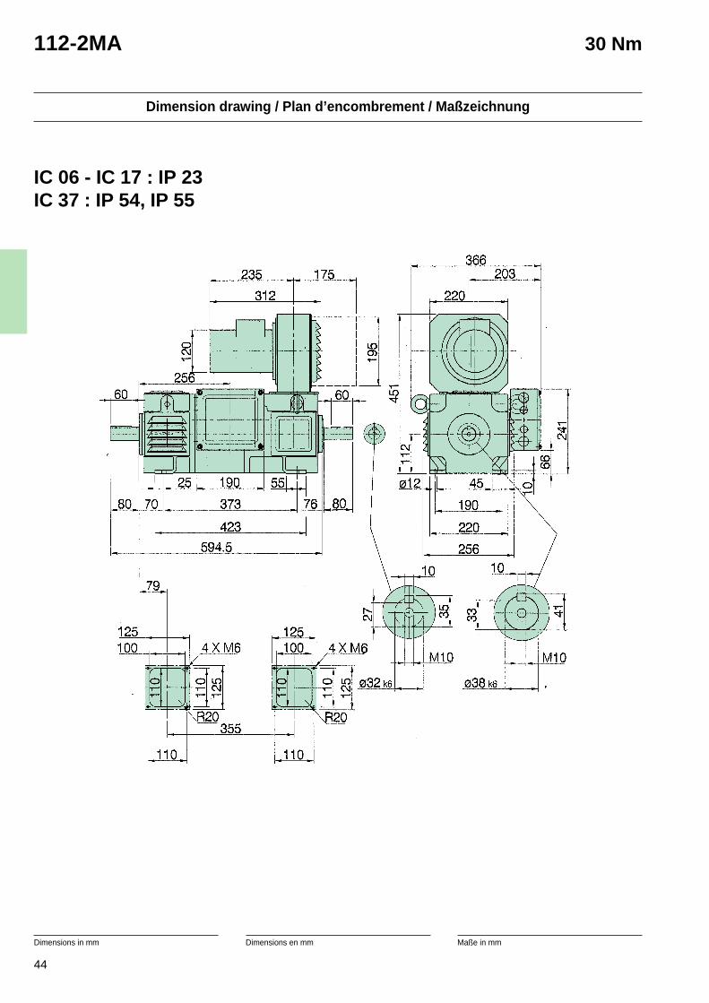
44
Dimension drawing / Plan d’encombrement / Maßzeichnung
Dimensions in mm Dimensions en mm Maße in mm
112-2MA 30 Nm
IC 06 - IC 17 : IP 23IC 37 : IP 54, IP 55
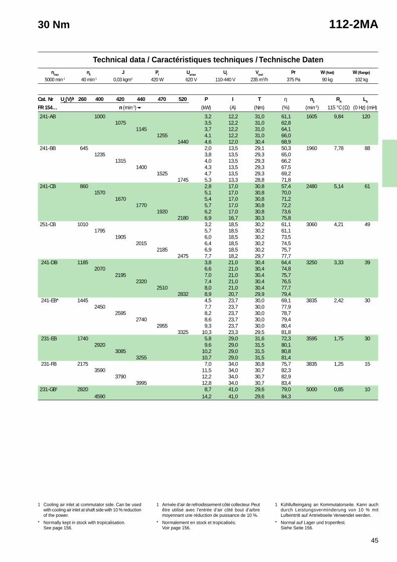
45
1 Cooling air inlet at commutator side. Can be usedwith cooling air inlet at shaft side with 10 % reductionof the power.
* Normally kept in stock with tropicalisation.See page 156.
1 Arrivée d’air de refroidissement côté collecteur. Peutêtre utilisé avec l’entrée d’air côté bout d’arbremoyennant une réduction de puissance de 10 %.
* Normalement en stock et tropicalisés.Voir page 156.
1 Kühllufteingang an Kommutatorseite. Kann auchdurch Leistungsverminderung von 10 % mitLufteintritt auf Antriebseite Verwendet werden.
* Normal auf Lager und tropenfest.Siehe Seite 156.
Technical data / Caractéristiques techniques / Technische Datennmax n0 J Pf Uamax Uf Vcool Pr W (foot) W (flange)
30 Nm 112-2MA
Cat. Nr Ua(V) 260 400 420 440 470 520 P I T η n2 RA LA
FR 154… n (min-1) (kW) (A) (Nm) (%) (min-1) 115 °C (Ω) (0 Hz) (mH)
241-AB 1000 3,2 12,2 31,0 61,1 1605 9,84 1201075 3,5 12,2 31,0 62,8
1145 3,7 12,2 31,0 64,11255 4,1 12,2 31,0 66,0
1440 4,6 12,0 30,4 68,9241-BB 645 2,0 13,5 29,1 50,3 1960 7,78 88
1235 3,8 13,5 29,3 65,01315 4,0 13,5 29,3 66,2
1400 4,3 13,5 29,3 67,51525 4,7 13,5 29,3 69,2
1745 5,3 13,3 28,8 71,8241-CB 860 2,8 17,0 30,8 57,4 2480 5,14 61
1570 5,1 17,0 30,8 70,01670 5,4 17,0 30,8 71,2
1770 5,7 17,0 30,8 72,21920 6,2 17,0 30,8 73,6
2180 6,9 16,7 30,3 75,8251-CB 1010 3,2 18,5 30,2 61,1 3060 4,21 49
1795 5,7 18,5 30,2 61,11905 6,0 18,5 30,2 73,5
2015 6,4 18,5 30,2 74,52185 6,9 18,5 30,2 75,7
2475 7,7 18,2 29,7 77,7 241-DB 1185 3,8 21,0 30,4 64,4 3250 3,33 39
2070 6,6 21,0 30,4 74,82195 7,0 21,0 30,4 75,7
2320 7,4 21,0 30,4 76,52510 8,0 21,0 30,4 77,7
2832 8,9 20,7 29,9 79,4 241-EB* 1445 4,5 23,7 30,0 69,1 3835 2,42 30
2450 7,7 23,7 30,0 77,92595 8,2 23,7 30,0 78,7
2740 8,6 23,7 30,0 79,42955 9,3 23,7 30,0 80,4
3325 10,3 23,3 29,5 81,8 231-EB 1740 5,8 29,0 31,6 72,3 3595 1,75 30
2920 9,6 29,0 31,5 80,13085 10,2 29,0 31,5 80,8
3255 10,7 29,0 31,5 81,4 231-FB 2175 7,0 34,0 30,8 75,7 3835 1,25 15
3590 11,5 34,0 30,7 82,33790 12,2 34,0 30,7 82,9
3995 12,8 34,0 30,7 83,4231-GB1 2820 8,7 41,0 29,6 79,0 5000 0,85 10
4590 14,2 41,0 29,6 84,3
5000 min-1 40 min-1 0,03 kgm2 420 W 620 V 110-440 V 235 m3/h 375 Pa 90 kg 102 kg
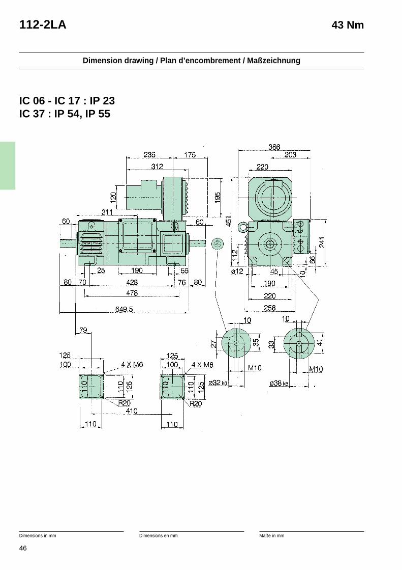
46
Dimension drawing / Plan d’encombrement / Maßzeichnung
Dimensions in mm Dimensions en mm Maße in mm
112-2LA 43 Nm
IC 06 - IC 17 : IP 23IC 37 : IP 54, IP 55
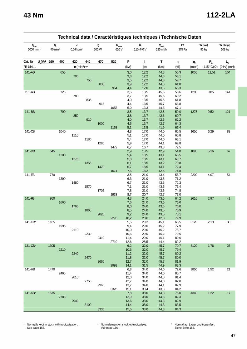
47
1 Cooling air inlet at commutator side. Can be usedwith cooling air inlet at shaft side with 10 % reductionof the power.
* Normally kept in stock with tropicalisation.See page 156.
1 Arrivée d’air de refroidissement côté collecteur. Peutêtre utilisé avec l’entrée d’air côté bout d’arbremoyennant une réduction de puissance de 10 %.
* Normalement en stock et tropicalisés.Voir page 156.
1 Kühllufteingang an Kommutatorseite. Kann auchdurch Leistungsverminderung von 10 % mitLufteintritt auf Antriebseite Verwendet werden.
* Normal auf Lager und tropenfest.Siehe Seite 156.
Technical data / Caractéristiques techniques / Technische Datennmax n0 J Pf Uamax Uf Vcool Pr W (foot) W (flange)
43 Nm 112-2LA
Cat. Nr Ua(V) 260 400 420 440 470 520 P I T η n2 RA LA
FR 154… n (min-1) (kW) (A) (Nm) (%) (min-1) 115 °C (Ω) (0 Hz) (mH)
141-AB 655 3,0 12,2 44,3 56,3 1055 11,51 164705 3,3 12,2 44,3 58,1
755 3,5 12,2 44,3 59,7830 3,9 12,2 44,3 61,8
964 4,4 12,0 43,6 65,3151-AB 725 3,5 13,5 45,6 58,6 1280 9,85 141
780 3,7 13,5 45,6 60,2835 4,0 13,5 45,6 61,8
915 4,4 13,5 45,7 63,81058 5,0 13,3 44,8 67,1
141-BB 790 3,5 13,7 42,6 59,0 1275 9,52 121850 3,8 13,7 42,6 60,7
910 4,0 13,7 42,6 62,21000 4,5 13,7 42,7 64,3
1153 5,1 13,5 41,9 67,4141-CB 1040 4,8 17,0 44,0 65,5 1650 6,29 83
1110 5,1 17,0 44,0 66,81180 5,4 17,0 44,0 68,1
1285 5,9 17,0 44,1 69,81472 6,7 16,7 43,3 72,5
141-DB 645 2,9 18,5 42,9 54,8 1895 5,16 671200 5,4 18,5 43,1 68,5
1275 5,8 18,5 43,1 69,71355 6,1 18,5 43,2 70,8
1470 6,7 18,5 43,1 72,41674 7,5 18,2 42,5 74,8
141-EB 770 3,5 21,0 43,4 58,7 2200 4,07 541390 6,3 21,0 43,5 71,2
1480 6,7 21,0 43,5 72,31570 7,1 21,0 43,5 73,4
1705 7,8 21,0 43,6 74,81933 8,7 20,7 42,7 77,0
141-FB 950 4,3 24,0 43,5 64,2 2610 2,97 411660 7,6 24,0 43,5 75,0
1765 8,0 24,0 43,5 76,01865 8,5 24,0 43,5 76,9
2020 9,2 24,0 43,5 78,12278 10,2 23,6 42,8 79,9
141-GB* 1165 5,5 29,2 45,1 68,5 3120 2,13 301995 9,4 29,0 45,2 77,9
2110 10,0 29,0 45,2 78,72230 10,5 29,0 45,2 79,5
2410 11,4 29,0 45,1 80,62710 12,6 28,5 44,4 82,2
131-CB* 1305 6,2 32,0 45,7 70,7 3120 1,76 252210 10,6 32,0 45,7 79,4
2340 11,2 32,0 45,7 80,22470 11,8 32,0 45,7 80,0
2665 12,7 32,0 45,7 81,92993 14,1 31,5 44,9 83,3
141-HB 1470 6,8 34,0 44,0 72,6 3850 1,52 212465 11,4 34,0 44,0 80,7
2610 12,0 34,0 44,0 81,42750 12,7 34,0 44,0 82,0
2965 13,7 34,0 44,1 82,93326 15,1 33,4 43,3 84,2
141-KB* 1675 7,8 38,0 44,3 75,0 4340 1,22 172785 12,9 38,0 44,3 82,3
2940 13,6 38,0 44,3 82,93100 14,4 38,0 44,3 83,5
3335 15,5 38,0 44,3 84,3
5000 min-1 40 min-1 0,04 kgm2 500 W 620 V 110-440 V 235 m3/h 375 Pa 96 kg 108 kg
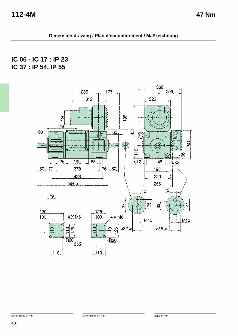
48
Dimension drawing / Plan d’encombrement / Maßzeichnung
Dimensions in mm Dimensions en mm Maße in mm
112-4M 47 Nm
IC 06 - IC 17 : IP 23IC 37 : IP 54, IP 55
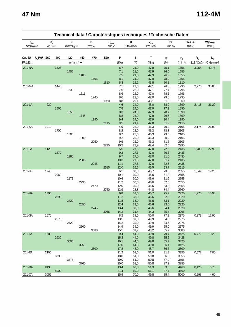
49
1 Cooling air inlet at commutator side. Can be usedwith cooling air inlet at shaft side with 10 % reductionof the power.
* Normally kept in stock with tropicalisation.See page 156.
1 Arrivée d’air de refroidissement côté collecteur. Peutêtre utilisé avec l’entrée d’air côté bout d’arbremoyennant une réduction de puissance de 10 %.
* Normalement en stock et tropicalisés.Voir page 156.
1 Kühllufteingang an Kommutatorseite. Kann auchdurch Leistungsverminderung von 10 % mitLufteintritt auf Antriebseite Verwendet werden.
* Normal auf Lager und tropenfest.Siehe Seite 156.
Technical data / Caractéristiques techniques / Technische Datennmax n0 J Pf Uamax Uf Vcool Pr W (foot) W (flange)
47 Nm 112-4M
Cat. Nr Ua(V) 260 400 420 440 470 520 P I T η n2 RA LA
FR 153… n (min-1) (kW) (A) (Nm) (%) (min-1) 115 °C (Ω) (0 Hz) (mH)
201-NA 1325 6,7 21,0 47,9 75,1 1655 3,258 40,751405 7,1 21,0 47,9 76,0 1655
1485 7,5 21,0 47,9 76,9 16551605 8,1 21,0 47,9 78,0 1655
1810 8,3 19,2 43,8 80,1 1810201-MA 1445 7,1 22,0 47,1 76,8 1795 2,776 35,80
1530 7,5 22,0 47,1 77,7 17951615 8,6 22,0 47,0 78,5 1795
1745 8,6 22,0 47,0 79,5 17951960 8,8 20,1 43,1 81,3 1960
201-LA 920 4,6 24,0 48,0 68,9 1890 2,416 31,201565 7,8 24,0 47,9 77,9 1890
1655 8,3 24,0 47,9 78,7 18901745 8,8 24,0 47,9 79,5 1890
1890 9,4 24,0 47,9 80,4 18902115 9,5 21,4 42,8 81,9 2115
201-KA 1010 4,9 25,0 46,3 70,2 2105 2,174 26,901700 8,2 25,0 46,3 78,8 2105
1800 8,7 25,0 46,3 79,5 21051900 9,2 25,0 46,3 80,2 2105
2050 9,9 25,0 46,3 81,2 21052295 10,2 22,9 42,4 82,5 2295
201-JA 1120 5,5 27,5 47,0 72,5 2435 1,783 22,901870 9,2 27,5 47,0 80,3 2435
1980 9,7 27,5 47,0 81,0 24352085 10,3 27,5 47,0 81,7 2435
2245 11,1 27,5 47,0 82,5 24352515 12,0 26,6 45,5 83,7 2515
201-lA 1240 6,1 30,0 46,7 73,8 2655 1,549 19,252060 10,1 30,0 46,6 81,2 2655
2175 10,6 30,0 46,6 81,9 26552295 11,2 30,0 46,6 82,5 2655
2470 12,0 30,0 46,6 83,3 26552760 12,9 28,8 44,8 84,4 2760
201-HA 1390 6,8 33,0 46,7 75,7 2920 1,275 15,902295 11,2 33,0 46,6 82,5 2920
2420 11,8 33,0 46,6 83,1 29202550 12,4 33,0 46,6 83,6 2920
2745 13,4 33,0 46,6 84,4 29203065 14,2 31,4 44,3 85,4 3065
201-GA 1575 8,2 39,0 50,0 77,9 2975 0,973 12,902575 13,5 39,0 49,9 84,0 2975
2720 14,2 39,0 49,9 84,6 29752860 14,9 39,0 49,9 85,0 2975
3080 15,5 37,7 48,2 85,7 3080201-FA 1800 9,4 44,0 49,9 79,7 3425 0,772 10,20
2930 15,3 44,0 49,8 85,2 34253090 16,1 44,0 49,8 85,7 3425
3250 17,0 44,0 49,8 86,1 34253500 17,8 43,0 48,7 86,7 3500
201-EA 2100 11,2 51,0 51,0 81,8 3855 0,573 7,803390 18,0 51,0 50,8 86,6 3855
3575 19,0 51,0 50,8 87,0 38553760 20,0 51,0 50,8 87,3 3855
201-DA 2495 13,4 60,0 51,3 83,5 4460 0,425 5,754000 21,4 60,0 51,1 87,7 4460
201-CA 3055 15,9 70,0 49,8 85,4 5000 0,298 4,00
5000 min-1 40 min-1 0,037 kgm2 625 W 550 V 110-440 V 270 m3/h 480 Pa 103 kg 115 kg
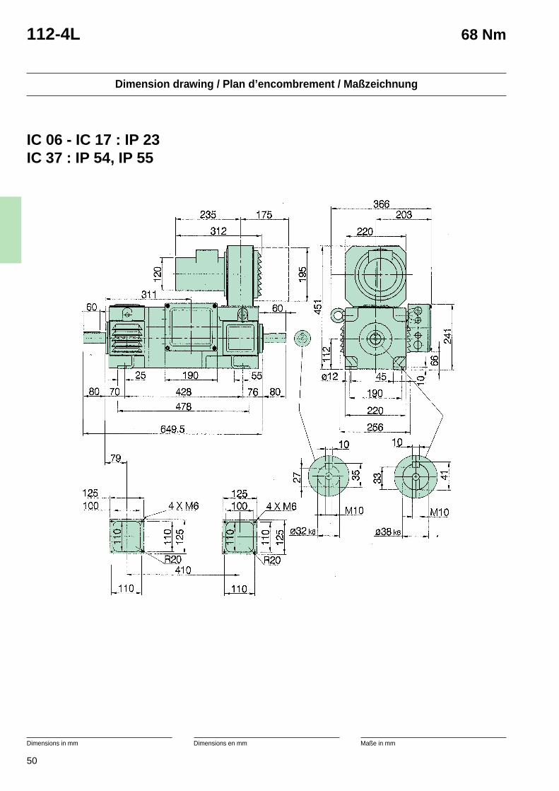
50
Dimension drawing / Plan d’encombrement / Maßzeichnung
Dimensions in mm Dimensions en mm Maße in mm
112-4L 68 Nm
IC 06 - IC 17 : IP 23IC 37 : IP 54, IP 55
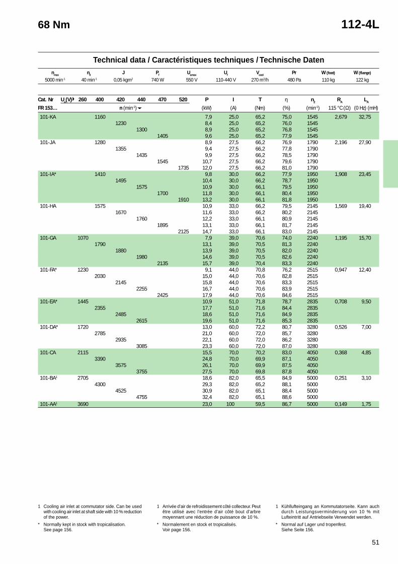
51
1 Cooling air inlet at commutator side. Can be usedwith cooling air inlet at shaft side with 10 % reductionof the power.
* Normally kept in stock with tropicalisation.See page 156.
1 Arrivée d’air de refroidissement côté collecteur. Peutêtre utilisé avec l’entrée d’air côté bout d’arbremoyennant une réduction de puissance de 10 %.
* Normalement en stock et tropicalisés.Voir page 156.
1 Kühllufteingang an Kommutatorseite. Kann auchdurch Leistungsverminderung von 10 % mitLufteintritt auf Antriebseite Verwendet werden.
* Normal auf Lager und tropenfest.Siehe Seite 156.
Technical data / Caractéristiques techniques / Technische Datennmax n0 J Pf Uamax Uf Vcool Pr W (foot) W (flange)
68 Nm 112-4L
Cat. Nr Ua(V) 260 400 420 440 470 520 P I T η n2 RA LA
FR 153… n (min-1) (kW) (A) (Nm) (%) (min-1) 115 °C (Ω) (0 Hz) (mH)
101-KA 1160 7,9 25,0 65,2 75,0 1545 2,679 32,751230 8,4 25,0 65,2 76,0 1545
1300 8,9 25,0 65,2 76,8 15451405 9,6 25,0 65,2 77,9 1545
101-JA 1280 8,9 27,5 66,2 76,9 1790 2,196 27,901355 9,4 27,5 66,2 77,8 1790
1435 9,9 27,5 66,2 78,5 17901545 10,7 27,5 66,2 79,6 1790
1735 12,0 27,5 66,2 81,0 1790101-IA* 1410 9,8 30,0 66,2 77,9 1950 1,908 23,45
1495 10,4 30,0 66,2 78,7 19501575 10,9 30,0 66,1 79,5 1950
1700 11,8 30,0 66,1 80,4 19501910 13,2 30,0 66,1 81,8 1950
101-HA 1575 10,9 33,0 66,2 79,5 2145 1,569 19,401670 11,6 33,0 66,2 80,2 2145
1760 12,2 33,0 66,1 80,9 21451895 13,1 33,0 66,1 81,7 2145
2125 14,7 33,0 66,1 83,0 2145101-GA 1070 7,9 39,0 70,6 74,0 2240 1,195 15,70
1790 13,1 39,0 70,5 81,3 22401880 13,9 39,0 70,5 82,0 2240
1980 14,6 39,0 70,5 82,6 22402135 15,7 39,0 70,4 83,3 2240
101-FA* 1230 9,1 44,0 70,8 76,2 2515 0,947 12,402030 15,0 44,0 70,6 82,8 2515
2145 15,8 44,0 70,6 83,3 25152255 16,7 44,0 70,6 83,9 2515
2425 17,9 44,0 70,6 84,6 2515101-EA* 1445 10,9 51,0 71,8 78,7 2835 0,708 9,50
2355 17,7 51,0 71,6 84,4 28352485 18,6 51,0 71,6 84,9 2835
2615 19,6 51,0 71,6 85,3 2835101-DA* 1720 13,0 60,0 72,2 80,7 3280 0,526 7,00
2785 21,0 60,0 72,0 85,7 32802935 22,1 60,0 72,0 86,2 3280
3085 23,3 60,0 72,0 87,0 3280101-CA 2115 15,5 70,0 70,2 83,0 4050 0,368 4,85
3390 24,8 70,0 69,9 87,1 40503575 26,1 70,0 69,9 87,5 4050
3755 27,5 70,0 69,8 87,8 4050101-BA1 2705 18,6 82,0 65,5 84,9 5000 0,251 3,10
4300 29,3 82,0 65,2 88,1 50004525 30,9 82,0 65,1 88,4 5000
4755 32,4 82,0 65,1 88,6 5000101-AA1 3690 23,0 100 59,5 86,7 5000 0,149 1,75
5000 min-1 40 min-1 0,05 kgm2 740 W 550 V 110-440 V 270 m3/h 480 Pa 110 kg 122 kg
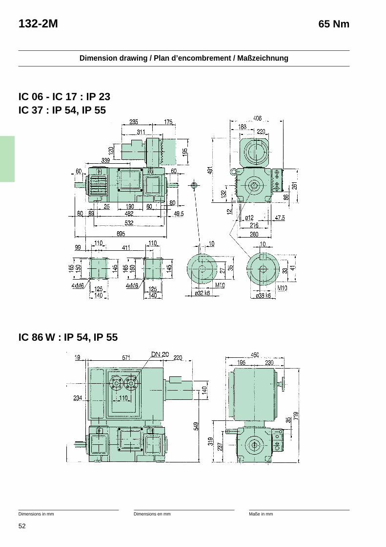
52
Dimension drawing / Plan d’encombrement / Maßzeichnung
Dimensions in mm Dimensions en mm Maße in mm
132-2M 65 Nm
IC 06 - IC 17 : IP 23IC 37 : IP 54, IP 55
IC 86 W : IP 54, IP 55
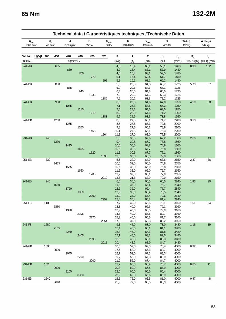
53
1 Cooling air inlet at commutator side. Can be usedwith cooling air inlet at shaft side with 10 % reductionof the power.
* Normally kept in stock with tropicalisation.See page 156.
1 Arrivée d’air de refroidissement côté collecteur. Peutêtre utilisé avec l’entrée d’air côté bout d’arbremoyennant une réduction de puissance de 10 %.
* Normalement en stock et tropicalisés.Voir page 156.
1 Kühllufteingang an Kommutatorseite. Kann auchdurch Leistungsverminderung von 10 % mitLufteintritt auf Antriebseite Verwendet werden.
* Normal auf Lager und tropenfest.Siehe Seite 156.
Technical data / Caractéristiques techniques / Technische Datennmax n0 J Pf Uamax Uf Vcool Pr W (foot) W (flange)
65 Nm 132-2M
Cat. Nr Ua(V) 260 400 420 440 470 520 P I T η n2 RA LA
FR 155… n (min-1) (kW) (A) (Nm) (%) (min-1) 115 °C (Ω) (0 Hz) (mH)
241-AB 605 4,0 16,4 63,1 56,1 1480 8,93 132650 4,3 16,4 63,1 57,9 1480
700 4,6 16,4 63,1 59,5 1480770 5,1 16,4 63,4 61,7 1480
898 5,8 16,1 62,1 65,2 1480241-BB 830 5,6 20,5 64,3 63,7 1725 5,73 87
885 6,0 20,5 64,3 65,1 1725945 6,4 20,5 64,3 66,5 1725
1035 7,0 20,5 64,3 68,3 17251186 7,9 20,2 63,3 71,2 1725
241-CB 980 6,6 23,3 64,6 67,0 1950 4,50 681045 7,1 23,3 64,6 68,3 1950
1110 7,5 23,3 64,6 69,5 19501210 8,2 23,3 64,6 71,2 1950
1383 9,2 22,9 63,5 73,8 1950241-DB 1200 8,3 27,5 66,1 71,7 2200 3,18 51
1275 8,8 27,5 66,1 72,8 22001350 9,3 27,5 66,1 73,9 2200
1465 10,1 27,5 66,1 75,3 22001664 11,3 27,0 65,0 77,5 2200
231-AB 745 5,3 30,5 67,6 62,2 1860 2,60 431330 9,4 30,5 67,7 73,8 1860
1415 10,0 30,5 67,7 74,9 18601495 10,6 30,5 67,7 75,8 1860
1620 11,5 30,5 67,7 77,1 18601835 12,8 30,0 66,5 79,0 1860
251-EB 830 5,6 32,0 64,9 63,6 2650 2,37 361465 10,0 32,0 65,0 74,8 2650
1555 10,6 32,0 65,0 75,8 26501650 11,2 32,0 65,0 76,7 2650
1785 12,2 32,0 65,1 77,9 26502019 13,5 31,5 63,9 79,9 2650
241-EB 945 6,6 36,0 66,5 66,5 2840 1,93 301650 11,5 36,0 66,4 76,7 2840
1750 12,2 36,0 66,4 77,7 28401850 12,9 36,0 66,4 78,5 2840
2000 13,9 36,0 66,4 79,6 28402257 15,4 35,4 65,3 81,4 2840
251-FB 1100 7,7 40,0 66,5 70,1 3160 1,51 241880 13,1 40,0 66,5 79,1 3160
1990 13,9 40,0 66,5 79,9 31602105 14,6 40,0 66,5 80,7 3160
2270 15,8 40,0 66,5 81,7 31602554 17,5 39,3 65,3 83,2 3160
241-FB 1280 9,1 46,0 68,0 73,0 3480 1,16 192155 15,4 46,0 68,1 81,1 3480
2280 16,3 46,0 68,1 81,8 34802405 17,1 46,0 68,1 82,5 3480
2595 18,5 46,0 68,1 83,3 34802911 20,4 45,2 66,9 84,7 3480
241-GB 1505 10,6 52,0 67,3 75,4 4000 0,92 152500 17,6 52,0 67,3 82,7 4000
2645 18,7 52,0 67,3 83,3 40002790 19,7 52,0 67,3 83,9 4000
3000 21,2 52,0 67,4 84,7 4000231-DB 1820 12,7 60,0 66,9 78,7 4000 0,65 11
2990 20,8 60,0 66,6 84,9 40003155 22,0 60,0 66,6 85,4 4000
3320 23,2 60,0 66,6 85,9 4000231-EB 2240 15,6 72,0 66,5 81,0 4000 0,47 8
3640 25,3 72,0 66,5 86,3 4000
5000 min-1 40 min-1 0,09 kgm2 550 W 620 V 110-440 V 435 m3/h 400 Pa 132 kg 147 kg
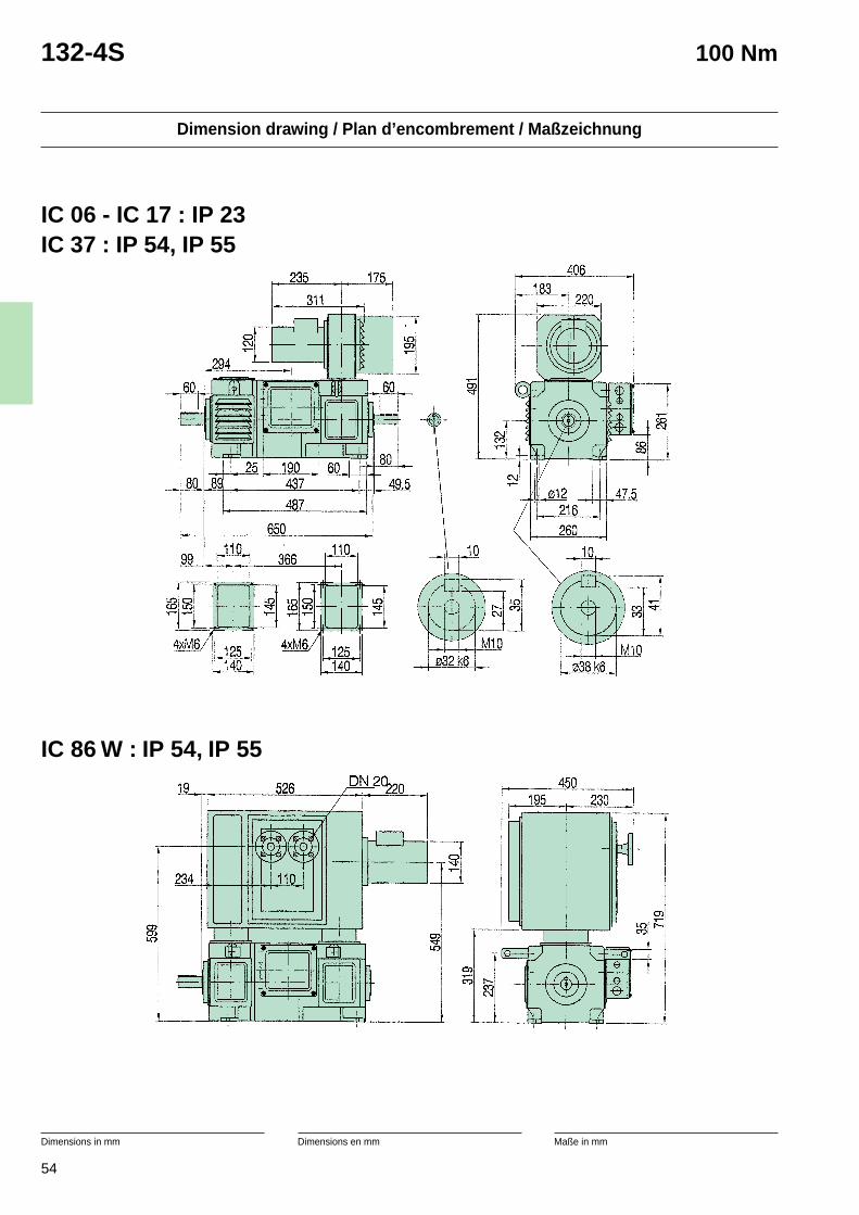
54
Dimension drawing / Plan d’encombrement / Maßzeichnung
Dimensions in mm Dimensions en mm Maße in mm
132-4S 100 Nm
IC 06 - IC 17 : IP 23IC 37 : IP 54, IP 55
IC 86 W : IP 54, IP 55
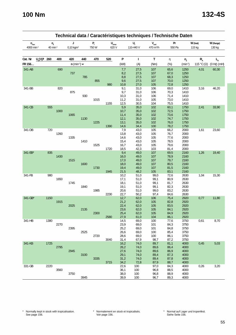
55
1 Cooling air inlet at commutator side. Can be usedwith cooling air inlet at shaft side with 10 % reductionof the power.
* Normally kept in stock with tropicalisation.See page 156.
1 Arrivée d’air de refroidissement côté collecteur. Peutêtre utilisé avec l’entrée d’air côté bout d’arbremoyennant une réduction de puissance de 10 %.
* Normalement en stock et tropicalisés.Voir page 156.
1 Kühllufteingang an Kommutatorseite. Kann auchdurch Leistungsverminderung von 10 % mitLufteintritt auf Antriebseite Verwendet werden.
* Normal auf Lager und tropenfest.Siehe Seite 156.
Technical data / Caractéristiques techniques / Technische Datennmax n0 J Pf Uamax Uf Vcool Pr W (foot) W (flange)
100 Nm 132-4S
Cat. Nr Ua(V) 260 400 420 440 470 520 P I T η n2 RA LA
FR 156… n (min-1) (kW) (A) (Nm) (%) (min-1) 115 °C (Ω) (0 Hz) (mH)
341-AB 690 7,7 27,5 107 65,6 1250 4,01 60,30737 8,2 27,5 107 67,0 1250
785 8,8 27,5 107 68,3 1250855 9,6 27,5 107 70,0 1250
980 10,8 27,0 105 72,8 1250341-BB 820 9,1 31,0 106 69,0 1410 3,16 46,20
875 9,7 31,0 106 70,3 1410930 10,3 31,0 106 71,4 1410
1015 11,2 31,0 105 73,0 14101155 12,5 30,5 104 75,5 1410
341-CB 555 5,9 35,0 102 60,1 1750 2,41 33,901000 10,7 35,0 102 72,5 1750
1065 11,4 35,0 102 73,6 17501130 12,1 35,0 102 74,7 1750
1225 13,1 35,0 102 76,0 17501390 14,6 34,4 100 78,2 1750
341-DB 720 7,9 43,0 105 66,2 2000 1,61 23,601260 13,8 43,0 105 76,7 2000
1335 14,6 43,0 105 77,6 20001410 15,4 43,0 105 78,5 2000
1525 16,7 43,0 105 79,6 20001720 18,5 42,3 103 81,4 2000
341-EB* 835 9,4 49,0 107 69,5 2160 1,26 19,401430 16,0 49,0 107 78,9 2160
1515 17,0 49,0 107 79,7 21601600 18,0 49,0 107 80,5 2160
1730 19,4 49,0 107 81,5 21601945 21,5 48,2 105 83,1 2160
341-FB 980 10,2 51,0 99,0 72,6 2630 1,04 15,301650 17,1 51,0 99,1 80,9 2630
1745 18,1 51,0 99,1 81,7 26301840 19,1 51,0 99,1 82,3 2630
1985 20,6 51,0 99,0 83,2 26302230 22,7 50,2 97,4 84,6 2630
341-GB* 1150 12,7 62,0 106 75,4 2920 0,77 11,801915 21,2 62,0 105 82,8 2920
2025 22,4 62,0 105 83,5 29202135 23,6 62,0 105 84,1 2920
2300 25,4 62,0 105 84,9 29202580 27,9 61,0 104 86,1 2920
341-HB 1380 14,5 69,0 100 77,6 3750 0,61 8,702270 23,9 69,0 101 84,3 3750
2395 25,2 69,0 101 84,8 37502525 26,6 69,0 100 85,4 3750
2720 28,6 69,0 100 86,1 37503040 31,4 67,9 98,7 87,2 3750
341-KB 1725 16,2 74,0 89,7 81,1 4000 0,45 5,032795 26,2 74,0 89,6 86,4 4000
2945 27,6 74,0 89,6 86,9 40003100 29,1 74,0 89,4 87,3 4000
3335 31,2 74,0 89,4 87,8 40003715 34,2 72,8 87,9 88,7 4000
331-GB 2220 22,6 100 97,0 84,3 4000 0,26 3,203560 36,1 100 96,8 88,5 4000
3750 38,0 100 96,8 88,9 40003945 39,9 100 96,7 89,3 4000
4000 min-1 40 min-1 0,10 kgm2 750 W 620 V 110-440 V 470 m3/h 550 Pa 115 kg 130 kg
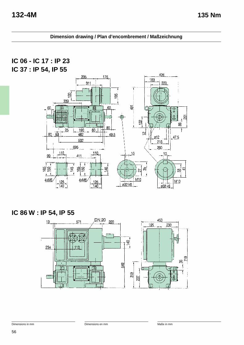
56
Dimension drawing / Plan d’encombrement / Maßzeichnung
Dimensions in mm Dimensions en mm Maße in mm
132-4M 135 Nm
IC 06 - IC 17 : IP 23IC 37 : IP 54, IP 55
IC 86 W : IP 54, IP 55
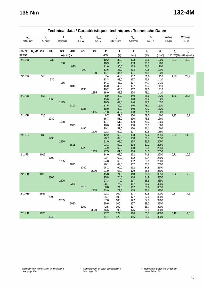
57
1 Cooling air inlet at commutator side. Can be usedwith cooling air inlet at shaft side with 10 % reductionof the power.
* Normally kept in stock with tropicalisation.See page 156.
1 Arrivée d’air de refroidissement côté collecteur. Peutêtre utilisé avec l’entrée d’air côté bout d’arbremoyennant une réduction de puissance de 10 %.
* Normalement en stock et tropicalisés.Voir page 156.
1 Kühllufteingang an Kommutatorseite. Kann auchdurch Leistungsverminderung von 10 % mitLufteintritt auf Antriebseite Verwendet werden.
* Normal auf Lager und tropenfest.Siehe Seite 156.
Technical data / Caractéristiques techniques / Technische Datennmax n0 J Pf Uamax Uf Vcool Pr W (foot) W (flange)
135 Nm 132-4M
Cat. Nr Ua(V) 260 400 420 440 470 520 P I T η n2 RA LA
FR 156… n (min-1) (kW) (A) (Nm) (%) (min-1) 115 °C (Ω) (0 Hz) (mH)
241-AB 730 10,2 35,0 133 68,8 1200 2,81 42,0780 10,9 35,0 133 70,1 1200
830 11,6 35,0 133 71,3 1200900 12,6 35,0 133 72,8 1200
1030 14,1 34,4 131 75,4 1200241-BB 515 7,4 43,0 137 61,6 1410 1,88 29,2
930 13,3 43,0 137 73,6 1410985 14,1 43,0 137 74,7 1410
1045 15,0 43,0 137 75,7 14101130 16,2 43,0 137 77,0 1410
1285 18,0 42,3 134 79,1 1410241-CB 605 8,9 49,0 140 65,6 1520 1,46 23,6
1060 15,6 49,0 140 76,2 15201125 16,5 49,0 140 77,2 1520
1190 17,5 49,0 140 78,1 15201285 18,9 49,0 140 79,2 1520
1455 21,0 48,2 138 81,1 1520241-DB 715 9,7 51,0 130 69,0 1860 1,22 18,7
1230 16,7 51,0 130 78,5 18601300 17,7 51,0 130 79,3 1860
1375 18,6 51,0 130 80,1 18601480 20,1 51,0 130 81,1 1860
1670 22,3 50,2 127 82,8 1860241-EB 845 12,2 62,0 138 72,2 2050 0,89 14,2
1430 20,7 62,0 138 80,7 20501510 21,9 62,0 138 81,5 2050
1595 23,1 62,0 138 82,2 20501720 24,9 62,0 138 83,1 2050
1935 27,5 61,0 136 84,5 2050241-FB* 1015 14,0 69,0 132 74,8 2500 0,71 10,5
1700 23,4 69,0 132 82,4 25001795 24,8 69,0 132 83,1 2500
1895 26,1 69,0 132 83,7 25002040 28,1 69,0 132 84,5 2500
2290 31,0 67,9 129 85,8 2500241-GB 1285 15,8 74,0 118 78,8 3350 0,52 7,3
2100 25,8 74,0 118 84,9 33502220 27,3 74,0 117 85,5 3350
2335 28,7 74,0 117 86,0 33502515 30,8 74,0 117 86,6 3350
2805 33,9 72,8 115 87,6 3350241-HB* 1665 22,1 100 127 82,5 3900 0,3 4,6
2690 35,7 100 127 87,4 39002835 37,6 100 127 87,8 3900
2980 39,6 100 127 88,2 39003200 42,5 100 127 88,7 3900
3570 46,5 98,3 125 89,5 3900231-HB 2280 27,7 122 116 85,1 4000 0,19 2,6
3645 44,1 122 116 88,9 4000
4000 min-1 40 min-1 0,12 kgm2 830 W 620 V 110-440 V 470 m3/h 550 Pa 145 kg 160 kg
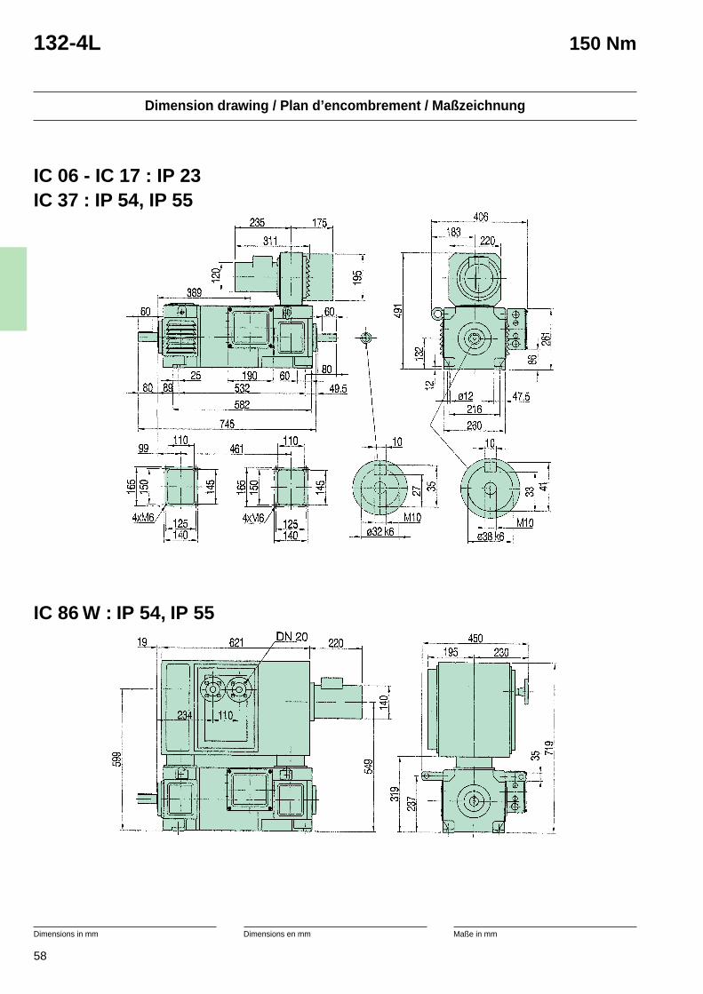
58
Dimension drawing / Plan d’encombrement / Maßzeichnung
Dimensions in mm Dimensions en mm Maße in mm
132-4L 150 Nm
IC 06 - IC 17 : IP 23IC 37 : IP 54, IP 55
IC 86 W : IP 54, IP 55
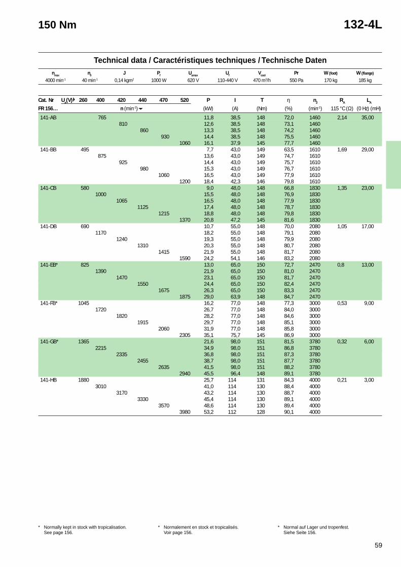
59
1 Cooling air inlet at commutator side. Can be usedwith cooling air inlet at shaft side with 10 % reductionof the power.
* Normally kept in stock with tropicalisation.See page 156.
1 Arrivée d’air de refroidissement côté collecteur. Peutêtre utilisé avec l’entrée d’air côté bout d’arbremoyennant une réduction de puissance de 10 %.
* Normalement en stock et tropicalisés.Voir page 156.
1 Kühllufteingang an Kommutatorseite. Kann auchdurch Leistungsverminderung von 10 % mitLufteintritt auf Antriebseite Verwendet werden.
* Normal auf Lager und tropenfest.Siehe Seite 156.
Technical data / Caractéristiques techniques / Technische Datennmax n0 J Pf Uamax Uf Vcool Pr W (foot) W (flange)
150 Nm 132-4L
Cat. Nr Ua(V) 260 400 420 440 470 520 P I T η n2 RA LA
FR 156… n (min-1) (kW) (A) (Nm) (%) (min-1) 115 °C (Ω) (0 Hz) (mH)
141-AB 765 11,8 38,5 148 72,0 1460 2,14 35,00810 12,6 38,5 148 73,1 1460
860 13,3 38,5 148 74,2 1460930 14,4 38,5 148 75,5 1460
1060 16,1 37,9 145 77,7 1460141-BB 495 7,7 43,0 149 63,5 1610 1,69 29,00
875 13,6 43,0 149 74,7 1610925 14,4 43,0 149 75,7 1610
980 15,3 43,0 149 76,7 16101060 16,5 43,0 149 77,9 1610
1200 18,4 42,3 146 79,8 1610141-CB 580 9,0 48,0 148 66,8 1830 1,35 23,00
1000 15,5 48,0 148 76,9 18301065 16,5 48,0 148 77,9 1830
1125 17,4 48,0 148 78,7 18301215 18,8 48,0 148 79,8 1830
1370 20,8 47,2 145 81,6 1830141-DB 690 10,7 55,0 148 70,0 2080 1,05 17,00
1170 18,2 55,0 148 79,1 20801240 19,3 55,0 148 79,9 2080
1310 20,3 55,0 148 80,7 20801415 21,9 55,0 148 81,7 2080
1590 24,2 54,1 146 83,2 2080141-EB* 825 13,0 65,0 150 72,7 2470 0,8 13,00
1390 21,9 65,0 150 81,0 24701470 23,1 65,0 150 81,7 2470
1550 24,4 65,0 150 82,4 24701675 26,3 65,0 150 83,3 2470
1875 29,0 63,9 148 84,7 2470141-FB* 1045 16,2 77,0 148 77,3 3000 0,53 9,00
1720 26,7 77,0 148 84,0 30001820 28,2 77,0 148 84,6 3000
1915 29,7 77,0 148 85,1 30002060 31,9 77,0 148 85,8 3000
2305 35,1 75,7 145 86,9 3000141-GB* 1365 21,6 98,0 151 81,5 3780 0,32 6,00
2215 34,9 98,0 151 86,8 37802335 36,8 98,0 151 87,3 3780
2455 38,7 98,0 151 87,7 37802635 41,5 98,0 151 88,2 3780
2940 45,5 96,4 148 89,1 3780141-HB 1880 25,7 114 131 84,3 4000 0,21 3,00
3010 41,0 114 130 88,4 40003170 43,2 114 130 88,7 4000
3330 45,4 114 130 89,1 40003570 48,6 114 130 89,4 4000
3980 53,2 112 128 90,1 4000
4000 min-1 40 min-1 0,14 kgm2 1000 W 620 V 110-440 V 470 m3/h 550 Pa 170 kg 185 kg
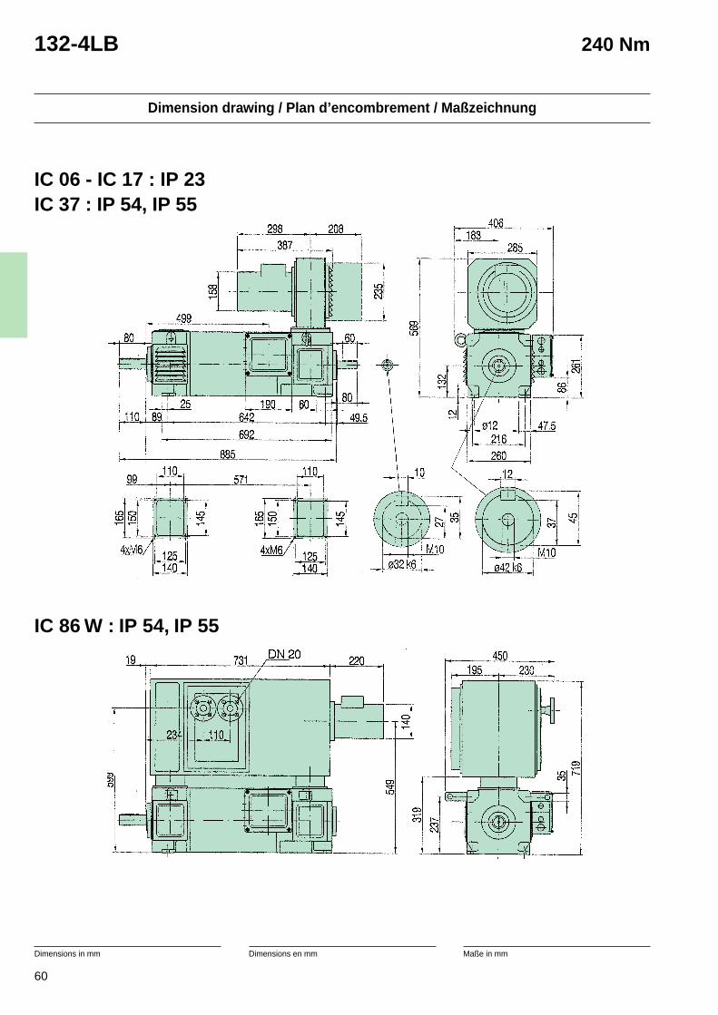
60
Dimension drawing / Plan d’encombrement / Maßzeichnung
Dimensions in mm Dimensions en mm Maße in mm
132-4LB 240 Nm
IC 06 - IC 17 : IP 23IC 37 : IP 54, IP 55
IC 86 W : IP 54, IP 55
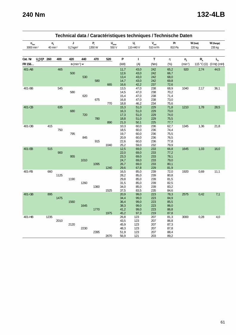
61
1 Cooling air inlet at commutator side. Can be usedwith cooling air inlet at shaft side with 10 % reductionof the power.
* Normally kept in stock with tropicalisation.See page 156.
1 Arrivée d’air de refroidissement côté collecteur. Peutêtre utilisé avec l’entrée d’air côté bout d’arbremoyennant une réduction de puissance de 10 %.
* Normalement en stock et tropicalisés.Voir page 156.
1 Kühllufteingang an Kommutatorseite. Kann auchdurch Leistungsverminderung von 10 % mitLufteintritt auf Antriebseite Verwendet werden.
* Normal auf Lager und tropenfest.Siehe Seite 156.
Technical data / Caractéristiques techniques / Technische Datennmax n0 J Pf Uamax Uf Vcool Pr W (foot) W (flange)
240 Nm 132-4LB
3000 min-1 40 min-1 0,2 kgm2 1350 W 550 V 110-440 V 510 m3/h 810 Pa 220 kg 235 kg
Cat. Nr Ua(V) 260 400 420 440 470 520 P I T η n2 RA LA
FR 156… n (min-1) (kW) (A) (Nm) (%) (min-1) 115 °C (Ω) (0 Hz) (mH)
401-AB 465 11,7 43,0 242 65,2 920 2,74 44,5500 12,6 43,0 242 66,7
530 13,4 43,0 242 68,0580 14,7 43,0 242 69,8
665 16,6 42,2 237 72,6401-BB 545 13,5 47,0 238 68,9 1040 2,17 36,1
580 14,5 47,0 238 70,2620 15,4 47,0 238 71,4
675 16,8 47,0 238 73,0770 18,8 46,2 234 75,6
401-CB 635 15,3 51,0 229 71,8 1210 1,78 28,5680 16,3 51,0 229 73,0
720 17,3 51,0 229 74,0780 18,8 51,0 229 75,5
890 21,0 50,1 225 77,7401-DB 415 10,3 60,0 236 62,7 1345 1,36 21,8
750 18,5 60,0 236 74,4795 19,7 60,0 236 75,5
845 20,9 60,0 236 76,5915 22,6 60,0 236 77,8
1040 25,2 59,0 232 79,9401-EB 515 12,5 69,0 233 66,8 1645 1,03 16,0
900 22,0 69,0 233 77,2955 23,3 69,0 233 78,1
1010 24,7 69,0 233 79,01095 26,7 69,0 233 80,1
1240 29,6 67,8 229 81,9401-FB 660 16,5 85,0 239 72,0 1920 0,69 11,1
1125 28,2 85,0 239 80,81190 29,8 85,0 239 81,5
1260 31,5 85,0 239 82,51360 34,0 85,0 239 83,2
1525 37,5 83,5 235 84,6401-GB 895 20,9 99,0 223 78,3 2575 0,42 7,1
1475 34,4 99,0 223 84,91560 36,4 99,0 223 85,5
1645 38,3 99,0 223 86,01770 41,2 99,0 223 86,8
1975 45,2 97,3 219 87,8401-HB 1235 26,8 123 207 81,3 3000 0,28 4,0
2010 43,5 123 207 86,82120 45,9 123 207 87,3
2230 48,3 123 207 87,82395 51,9 123 207 88,4
2670 56,9 121 203 89,2
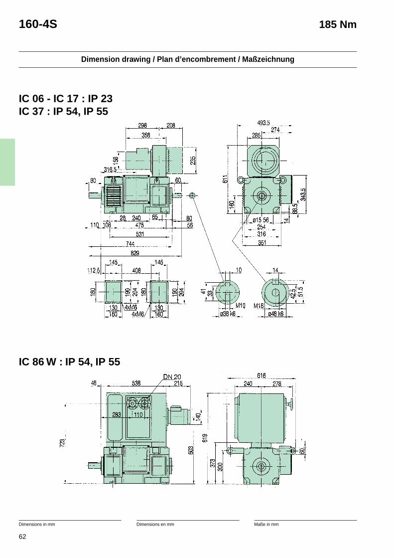
62
Dimension drawing / Plan d’encombrement / Maßzeichnung
Dimensions in mm Dimensions en mm Maße in mm
160-4S 185 Nm
IC 06 - IC 17 : IP 23IC 37 : IP 54, IP 55
IC 86 W : IP 54, IP 55
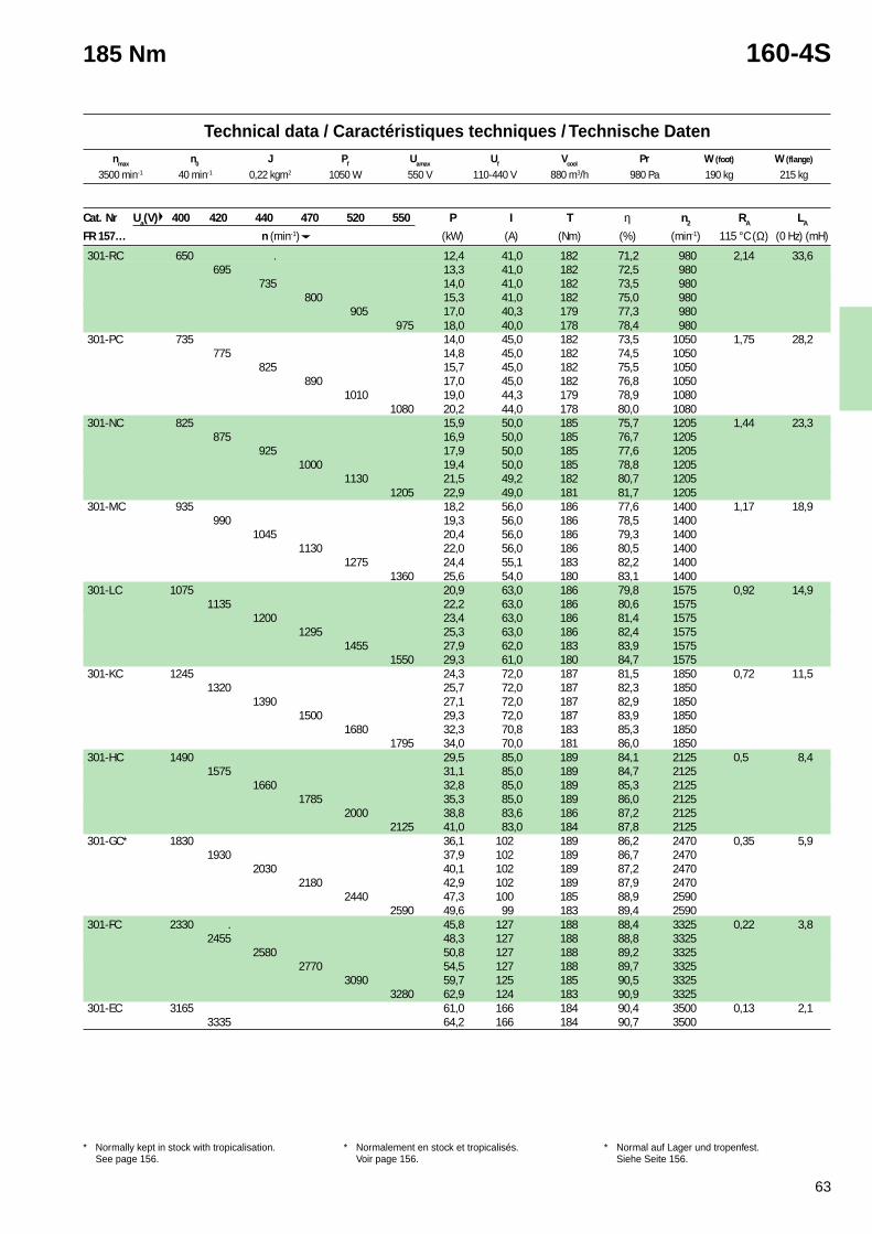
63
Technical data / Caractéristiques techniques / Technische Datennmax n0 J Pf Uamax Uf Vcool Pr W (foot) W (flange)
1 Cooling air inlet at commutator side. Can be usedwith cooling air inlet at shaft side with 10 % reductionof the power.
* Normally kept in stock with tropicalisation.See page 156.
1 Arrivée d’air de refroidissement côté collecteur. Peutêtre utilisé avec l’entrée d’air côté bout d’arbremoyennant une réduction de puissance de 10 %.
* Normalement en stock et tropicalisés.Voir page 156.
1 Kühllufteingang an Kommutatorseite. Kann auchdurch Leistungsverminderung von 10 % mitLufteintritt auf Antriebseite Verwendet werden.
* Normal auf Lager und tropenfest.Siehe Seite 156.
185 Nm 160-4S
Cat. Nr Ua(V) 400 420 440 470 520 550 P I T η n2 RA LA
FR 157… n (min-1) (kW) (A) (Nm) (%) (min-1) 115 °C (Ω) (0 Hz) (mH)
301-RC 650 . 12,4 41,0 182 71,2 980 2,14 33,6695 13,3 41,0 182 72,5 980
735 14,0 41,0 182 73,5 980800 15,3 41,0 182 75,0 980
905 17,0 40,3 179 77,3 980975 18,0 40,0 178 78,4 980
301-PC 735 14,0 45,0 182 73,5 1050 1,75 28,2775 14,8 45,0 182 74,5 1050
825 15,7 45,0 182 75,5 1050890 17,0 45,0 182 76,8 1050
1010 19,0 44,3 179 78,9 10801080 20,2 44,0 178 80,0 1080
301-NC 825 15,9 50,0 185 75,7 1205 1,44 23,3875 16,9 50,0 185 76,7 1205
925 17,9 50,0 185 77,6 12051000 19,4 50,0 185 78,8 1205
1130 21,5 49,2 182 80,7 12051205 22,9 49,0 181 81,7 1205
301-MC 935 18,2 56,0 186 77,6 1400 1,17 18,9990 19,3 56,0 186 78,5 1400
1045 20,4 56,0 186 79,3 14001130 22,0 56,0 186 80,5 1400
1275 24,4 55,1 183 82,2 14001360 25,6 54,0 180 83,1 1400
301-LC 1075 20,9 63,0 186 79,8 1575 0,92 14,91135 22,2 63,0 186 80,6 1575
1200 23,4 63,0 186 81,4 15751295 25,3 63,0 186 82,4 1575
1455 27,9 62,0 183 83,9 15751550 29,3 61,0 180 84,7 1575
301-KC 1245 24,3 72,0 187 81,5 1850 0,72 11,51320 25,7 72,0 187 82,3 1850
1390 27,1 72,0 187 82,9 18501500 29,3 72,0 187 83,9 1850
1680 32,3 70,8 183 85,3 18501795 34,0 70,0 181 86,0 1850
301-HC 1490 29,5 85,0 189 84,1 2125 0,5 8,41575 31,1 85,0 189 84,7 2125
1660 32,8 85,0 189 85,3 21251785 35,3 85,0 189 86,0 2125
2000 38,8 83,6 186 87,2 21252125 41,0 83,0 184 87,8 2125
301-GC* 1830 36,1 102 189 86,2 2470 0,35 5,91930 37,9 102 189 86,7 2470
2030 40,1 102 189 87,2 24702180 42,9 102 189 87,9 2470
2440 47,3 100 185 88,9 25902590 49,6 99 183 89,4 2590
301-FC 2330 . 45,8 127 188 88,4 3325 0,22 3,82455 48,3 127 188 88,8 3325
2580 50,8 127 188 89,2 33252770 54,5 127 188 89,7 3325
3090 59,7 125 185 90,5 33253280 62,9 124 183 90,9 3325
301-EC 3165 61,0 166 184 90,4 3500 0,13 2,13335 64,2 166 184 90,7 3500
3500 min-1 40 min-1 0,22 kgm2 1050 W 550 V 110-440 V 880 m3/h 980 Pa 190 kg 215 kg
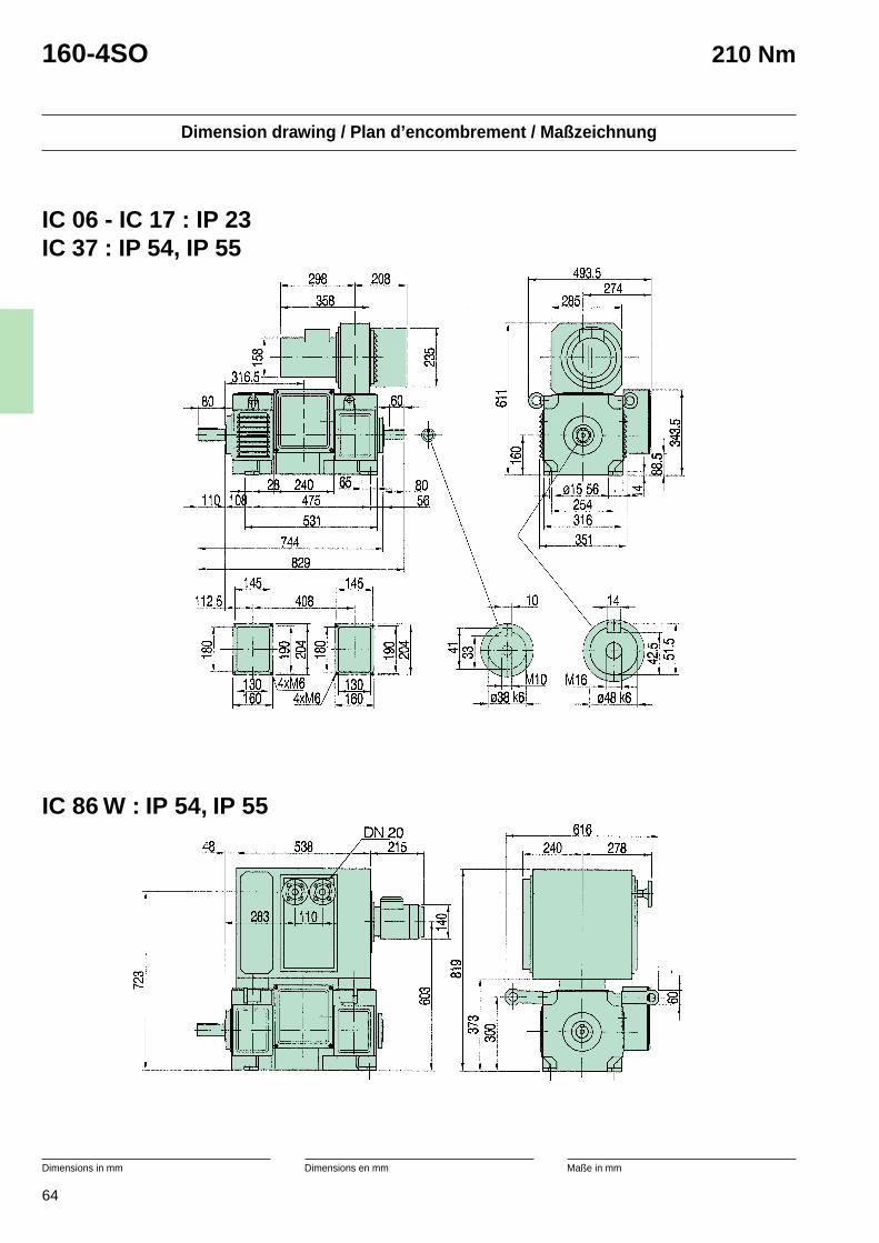
64
Dimension drawing / Plan d’encombrement / Maßzeichnung
Dimensions in mm Dimensions en mm Maße in mm
160-4SO 210 Nm
IC 06 - IC 17 : IP 23IC 37 : IP 54, IP 55
IC 86 W : IP 54, IP 55
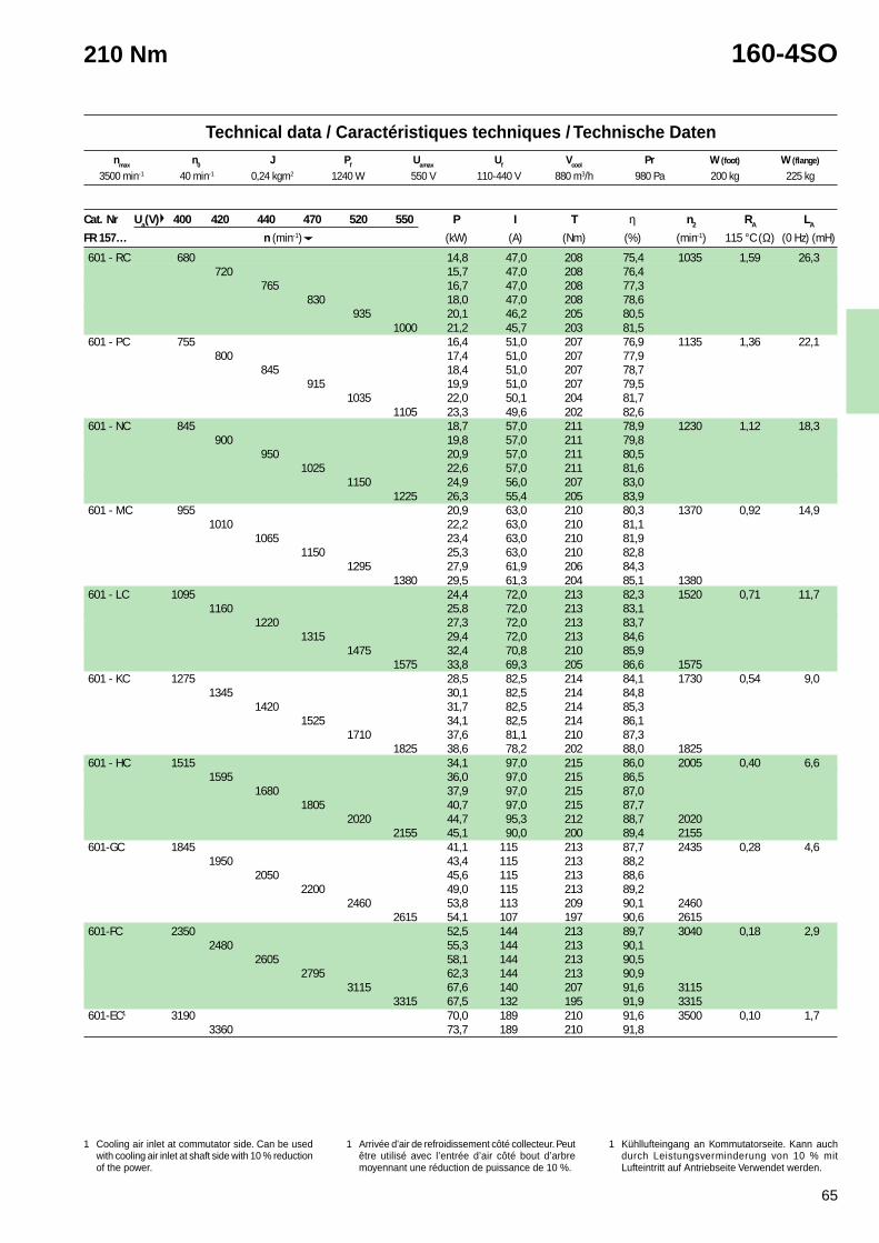
65
Technical data / Caractéristiques techniques / Technische Datennmax n0 J Pf Uamax Uf Vcool Pr W (foot) W (flange)
1 Cooling air inlet at commutator side. Can be usedwith cooling air inlet at shaft side with 10 % reductionof the power.
* Normally kept in stock with tropicalisation.See page 156.
1 Arrivée d’air de refroidissement côté collecteur. Peutêtre utilisé avec l’entrée d’air côté bout d’arbremoyennant une réduction de puissance de 10 %.
* Normalement en stock et tropicalisés.Voir page 156.
1 Kühllufteingang an Kommutatorseite. Kann auchdurch Leistungsverminderung von 10 % mitLufteintritt auf Antriebseite Verwendet werden.
* Normal auf Lager und tropenfest.Siehe Seite 156.
210 Nm 160-4SO
3500 min-1 40 min-1 0,24 kgm2 1240 W 550 V 110-440 V 880 m3/h 980 Pa 200 kg 225 kg
Cat. Nr Ua(V) 400 420 440 470 520 550 P I T η n2 RA LA
FR 157… n (min-1) (kW) (A) (Nm) (%) (min-1) 115 °C (Ω) (0 Hz) (mH)
601 - RC 680 14,8 47,0 208 75,4 1035 1,59 26,3720 15,7 47,0 208 76,4
765 16,7 47,0 208 77,3830 18,0 47,0 208 78,6
935 20,1 46,2 205 80,51000 21,2 45,7 203 81,5
601 - PC 755 16,4 51,0 207 76,9 1135 1,36 22,1800 17,4 51,0 207 77,9
845 18,4 51,0 207 78,7915 19,9 51,0 207 79,5
1035 22,0 50,1 204 81,71105 23,3 49,6 202 82,6
601 - NC 845 18,7 57,0 211 78,9 1230 1,12 18,3900 19,8 57,0 211 79,8
950 20,9 57,0 211 80,51025 22,6 57,0 211 81,6
1150 24,9 56,0 207 83,01225 26,3 55,4 205 83,9
601 - MC 955 20,9 63,0 210 80,3 1370 0,92 14,91010 22,2 63,0 210 81,1
1065 23,4 63,0 210 81,91150 25,3 63,0 210 82,8
1295 27,9 61,9 206 84,31380 29,5 61,3 204 85,1 1380
601 - LC 1095 24,4 72,0 213 82,3 1520 0,71 11,71160 25,8 72,0 213 83,1
1220 27,3 72,0 213 83,71315 29,4 72,0 213 84,6
1475 32,4 70,8 210 85,91575 33,8 69,3 205 86,6 1575
601 - KC 1275 28,5 82,5 214 84,1 1730 0,54 9,01345 30,1 82,5 214 84,8
1420 31,7 82,5 214 85,31525 34,1 82,5 214 86,1
1710 37,6 81,1 210 87,31825 38,6 78,2 202 88,0 1825
601 - HC 1515 34,1 97,0 215 86,0 2005 0,40 6,61595 36,0 97,0 215 86,5
1680 37,9 97,0 215 87,01805 40,7 97,0 215 87,7
2020 44,7 95,3 212 88,7 20202155 45,1 90,0 200 89,4 2155
601-GC 1845 41,1 115 213 87,7 2435 0,28 4,61950 43,4 115 213 88,2
2050 45,6 115 213 88,62200 49,0 115 213 89,2
2460 53,8 113 209 90,1 24602615 54,1 107 197 90,6 2615
601-FC 2350 52,5 144 213 89,7 3040 0,18 2,92480 55,3 144 213 90,1
2605 58,1 144 213 90,52795 62,3 144 213 90,9
3115 67,6 140 207 91,6 31153315 67,5 132 195 91,9 3315
601-EC1 3190 70,0 189 210 91,6 3500 0,10 1,73360 73,7 189 210 91,8
1 Cooling air inlet at commutator side. Can be usedwith cooling air inlet at shaft side with 10 % reductionof the power.
1 Arrivée d’air de refroidissement côté collecteur. Peutêtre utilisé avec l’entrée d’air côté bout d’arbremoyennant une réduction de puissance de 10 %.
1 Kühllufteingang an Kommutatorseite. Kann auchdurch Leistungsverminderung von 10 % mitLufteintritt auf Antriebseite Verwendet werden.
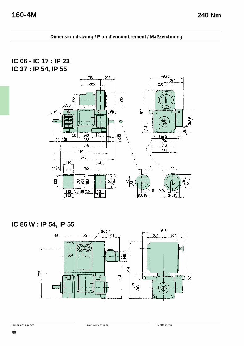
66
Dimension drawing / Plan d’encombrement / Maßzeichnung
Dimensions in mm Dimensions en mm Maße in mm
160-4M 240 Nm
IC 06 - IC 17 : IP 23IC 37 : IP 54, IP 55
IC 86 W : IP 54, IP 55
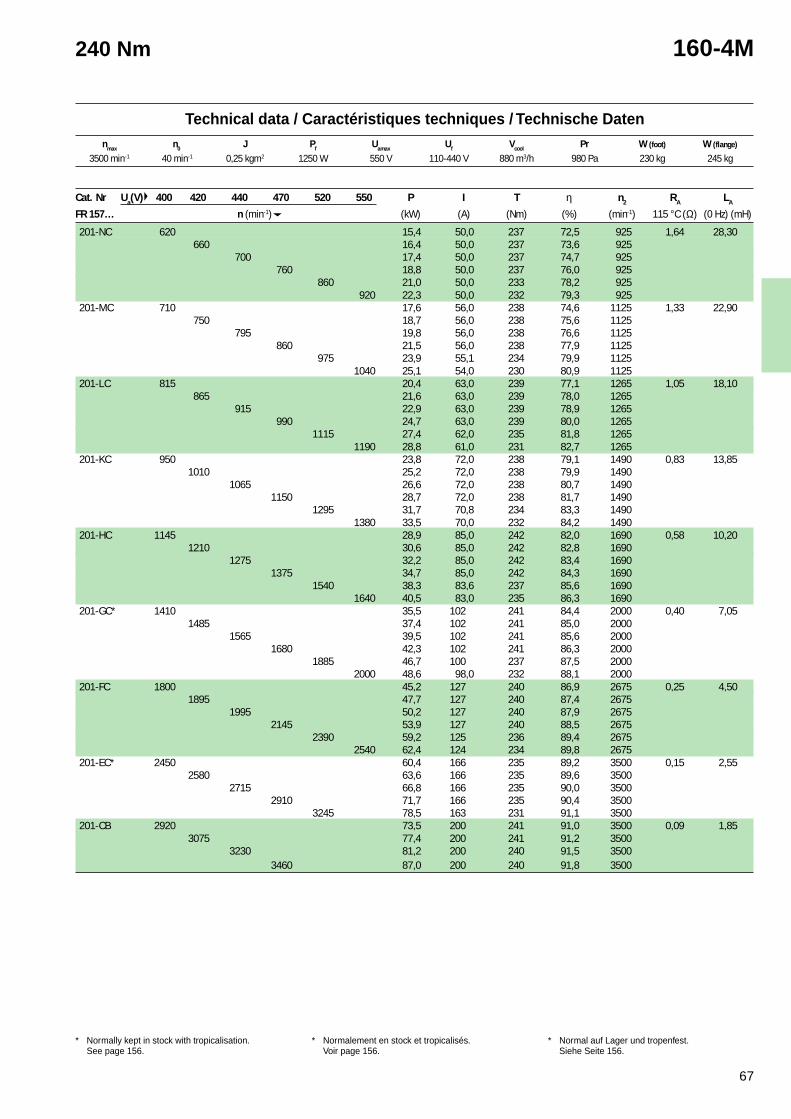
67
Technical data / Caractéristiques techniques / Technische Datennmax n0 J Pf Uamax Uf Vcool Pr W (foot) W (flange)
1 Cooling air inlet at commutator side. Can be usedwith cooling air inlet at shaft side with 10 % reductionof the power.
* Normally kept in stock with tropicalisation.See page 156.
1 Arrivée d’air de refroidissement côté collecteur. Peutêtre utilisé avec l’entrée d’air côté bout d’arbremoyennant une réduction de puissance de 10 %.
* Normalement en stock et tropicalisés.Voir page 156.
1 Kühllufteingang an Kommutatorseite. Kann auchdurch Leistungsverminderung von 10 % mitLufteintritt auf Antriebseite Verwendet werden.
* Normal auf Lager und tropenfest.Siehe Seite 156.
240 Nm 160-4M
Cat. Nr Ua(V) 400 420 440 470 520 550 P I T η n2 RA LA
FR 157… n (min-1) (kW) (A) (Nm) (%) (min-1) 115 °C (Ω) (0 Hz) (mH)
201-NC 620 15,4 50,0 237 72,5 925 1,64 28,30660 16,4 50,0 237 73,6 925
700 17,4 50,0 237 74,7 925760 18,8 50,0 237 76,0 925
860 21,0 50,0 233 78,2 925920 22,3 50,0 232 79,3 925
201-MC 710 17,6 56,0 238 74,6 1125 1,33 22,90750 18,7 56,0 238 75,6 1125
795 19,8 56,0 238 76,6 1125860 21,5 56,0 238 77,9 1125
975 23,9 55,1 234 79,9 11251040 25,1 54,0 230 80,9 1125
201-LC 815 20,4 63,0 239 77,1 1265 1,05 18,10865 21,6 63,0 239 78,0 1265
915 22,9 63,0 239 78,9 1265990 24,7 63,0 239 80,0 1265
1115 27,4 62,0 235 81,8 12651190 28,8 61,0 231 82,7 1265
201-KC 950 23,8 72,0 238 79,1 1490 0,83 13,851010 25,2 72,0 238 79,9 1490
1065 26,6 72,0 238 80,7 14901150 28,7 72,0 238 81,7 1490
1295 31,7 70,8 234 83,3 14901380 33,5 70,0 232 84,2 1490
201-HC 1145 28,9 85,0 242 82,0 1690 0,58 10,201210 30,6 85,0 242 82,8 1690
1275 32,2 85,0 242 83,4 16901375 34,7 85,0 242 84,3 1690
1540 38,3 83,6 237 85,6 16901640 40,5 83,0 235 86,3 1690
201-GC* 1410 35,5 102 241 84,4 2000 0,40 7,051485 37,4 102 241 85,0 2000
1565 39,5 102 241 85,6 20001680 42,3 102 241 86,3 2000
1885 46,7 100 237 87,5 20002000 48,6 98,0 232 88,1 2000
201-FC 1800 45,2 127 240 86,9 2675 0,25 4,501895 47,7 127 240 87,4 2675
1995 50,2 127 240 87,9 26752145 53,9 127 240 88,5 2675
2390 59,2 125 236 89,4 26752540 62,4 124 234 89,8 2675
201-EC* 2450 60,4 166 235 89,2 3500 0,15 2,552580 63,6 166 235 89,6 3500
2715 66,8 166 235 90,0 35002910 71,7 166 235 90,4 3500
3245 78,5 163 231 91,1 3500201-CB 2920 73,5 200 241 91,0 3500 0,09 1,85
3075 77,4 200 241 91,2 35003230 81,2 200 240 91,5 3500
3460 87,0 200 240 91,8 3500
3500 min-1 40 min-1 0,25 kgm2 1250 W 550 V 110-440 V 880 m3/h 980 Pa 230 kg 245 kg
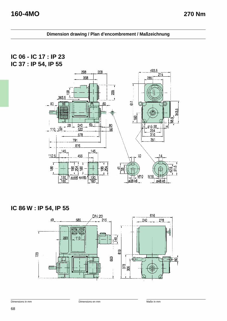
68
Dimension drawing / Plan d’encombrement / Maßzeichnung
Dimensions in mm Dimensions en mm Maße in mm
160-4MO 270 Nm
IC 06 - IC 17 : IP 23IC 37 : IP 54, IP 55
IC 86 W : IP 54, IP 55
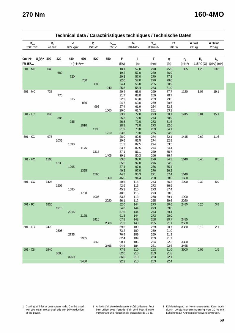
69
Technical data / Caractéristiques techniques / Technische Datennmax n0 J Pf Uamax Uf Vcool Pr W (foot) W (flange)
1 Cooling air inlet at commutator side. Can be usedwith cooling air inlet at shaft side with 10 % reductionof the power.
* Normally kept in stock with tropicalisation.See page 156.
1 Arrivée d’air de refroidissement côté collecteur. Peutêtre utilisé avec l’entrée d’air côté bout d’arbremoyennant une réduction de puissance de 10 %.
* Normalement en stock et tropicalisés.Voir page 156.
1 Kühllufteingang an Kommutatorseite. Kann auchdurch Leistungsverminderung von 10 % mitLufteintritt auf Antriebseite Verwendet werden.
* Normal auf Lager und tropenfest.Siehe Seite 156.
270 Nm 160-4MO
3500 min-1 40 min-1 0,27 kgm2 1500 W 550 V 110-440 V 880 m3/h 980 Pa 230 kg 255 kg
Cat. Nr Ua(V) 400 420 440 470 520 550 P I T η n2 RA LA
FR 157… n (min-1) (kW) (A) (Nm) (%) (min-1) 115 °C (Ω) (0 Hz) (mH)
501 - NC 640 18,1 57,0 270 75,9 985 1,28 23,6680 19,2 57,0 270 76,9
720 20,3 57,0 270 77,8780 22,0 57,0 270 79,0
880 24,4 56,0 265 80,9940 25,8 55,4 263 81,9
501 - MC 725 20,4 63,0 269 77,7 1120 1,05 19,1770 21,7 63,0 269 78,7
815 22,9 63,0 269 79,5880 24,7 63,0 269 80,6
995 27,4 61,9 264 82,31060 29,0 61,3 261 83,2
501 - LC 840 23,9 72,0 273 80,1 1245 0,81 15,1885 25,3 72,0 273 80,9
935 26,8 72,0 273 81,61010 28,9 72,0 273 82,6
1135 31,9 70,8 269 84,11210 33,6 70,0 265 84,9
501 - KC 975 28,0 82,5 274 82,1 1415 0,62 11,61035 29,6 82,5 274 82,9
1090 31,2 82,5 274 83,51175 33,7 82,5 274 84,4
1315 37,1 81,1 269 85,71405 39,1 80,3 266 86,4
501 - HC 1165 33,6 97,0 276 84,3 1640 0,45 8,51230 35,5 97,0 276 84,9
1295 37,4 97,0 276 85,41395 40,3 97,0 276 86,2
1560 44,3 95,3 271 87,4 16401660 46,6 94,4 268 88,0 1660
501 - GC 1425 40,6 115 273 86,3 1990 0,32 5,91505 42,9 115 273 86,9
1585 45,2 115 273 87,41700 48,5 115 273 88,0
1905 53,3 113 268 89,1 19902020 56,1 112 265 89,6 2020
501 - FC 1820 52,0 144 273 88,6 2485 0,20 3,81915 54,8 144 273 89,0
2015 57,6 144 273 89,42165 61,8 144 273 90,0
2415 67,8 142 268 90,7 24852560 71,2 140 265 91,1 2560
501 - EC1 2470 69,5 189 269 90,7 3380 0,12 2,12605 73,2 189 269 91,0
2735 76,9 189 269 91,32935 82,4 189 269 91,7
3265 90,1 186 264 92,3 33803465 94,6 184 261 92,6 3465
501 - CB 2940 77,9 210 253 91,6 3500 0,09 1,53095 82,0 210 253 91,8
3250 86,0 210 253 92,13480 92,2 210 253 92,4
1 Cooling air inlet at commutator side. Can be usedwith cooling air inlet at shaft side with 10 % reductionof the power.
1 Arrivée d’air de refroidissement côté collecteur. Peutêtre utilisé avec l’entrée d’air côté bout d’arbremoyennant une réduction de puissance de 10 %.
1 Kühllufteingang an Kommutatorseite. Kann auchdurch Leistungsverminderung von 10 % mitLufteintritt auf Antriebseite Verwendet werden.
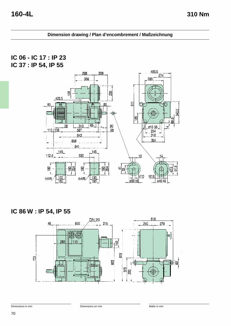
70
Dimension drawing / Plan d’encombrement / Maßzeichnung
Dimensions in mm Dimensions en mm Maße in mm
160-4L 310 Nm
IC 86 W : IP 54, IP 55
IC 06 - IC 17 : IP 23IC 37 : IP 54, IP 55
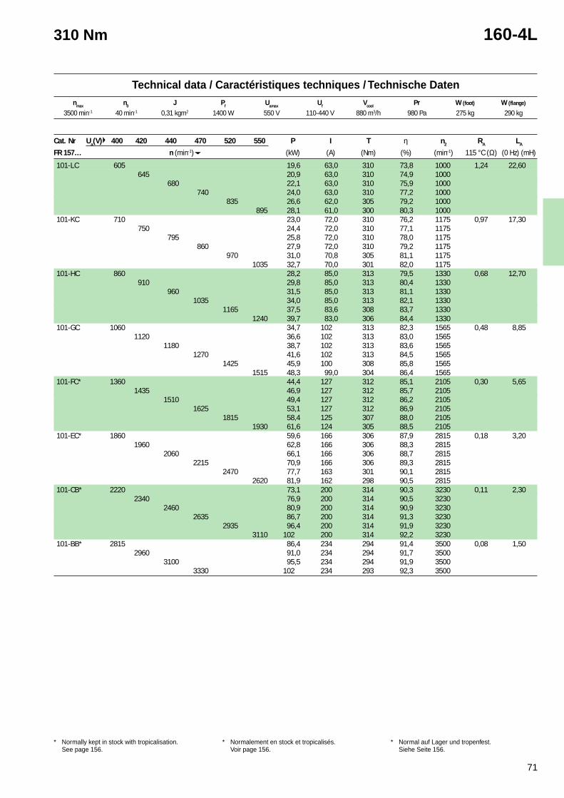
71
Technical data / Caractéristiques techniques / Technische Datennmax n0 J Pf Uamax Uf Vcool Pr W (foot) W (flange)
1 Cooling air inlet at commutator side. Can be usedwith cooling air inlet at shaft side with 10 % reductionof the power.
* Normally kept in stock with tropicalisation.See page 156.
1 Arrivée d’air de refroidissement côté collecteur. Peutêtre utilisé avec l’entrée d’air côté bout d’arbremoyennant une réduction de puissance de 10 %.
* Normalement en stock et tropicalisés.Voir page 156.
1 Kühllufteingang an Kommutatorseite. Kann auchdurch Leistungsverminderung von 10 % mitLufteintritt auf Antriebseite Verwendet werden.
* Normal auf Lager und tropenfest.Siehe Seite 156.
310 Nm 160-4L
Cat. Nr Ua(V) 400 420 440 470 520 550 P I T η n2 RA LA
FR 157… n (min-1) (kW) (A) (Nm) (%) (min-1) 115 °C (Ω) (0 Hz) (mH)
101-LC 605 19,6 63,0 310 73,8 1000 1,24 22,60645 20,9 63,0 310 74,9 1000
680 22,1 63,0 310 75,9 1000740 24,0 63,0 310 77,2 1000
835 26,6 62,0 305 79,2 1000895 28,1 61,0 300 80,3 1000
101-KC 710 23,0 72,0 310 76,2 1175 0,97 17,30750 24,4 72,0 310 77,1 1175
795 25,8 72,0 310 78,0 1175860 27,9 72,0 310 79,2 1175
970 31,0 70,8 305 81,1 11751035 32,7 70,0 301 82,0 1175
101-HC 860 28,2 85,0 313 79,5 1330 0,68 12,70910 29,8 85,0 313 80,4 1330
960 31,5 85,0 313 81,1 13301035 34,0 85,0 313 82,1 1330
1165 37,5 83,6 308 83,7 13301240 39,7 83,0 306 84,4 1330
101-GC 1060 34,7 102 313 82,3 1565 0,48 8,851120 36,6 102 313 83,0 1565
1180 38,7 102 313 83,6 15651270 41,6 102 313 84,5 1565
1425 45,9 100 308 85,8 15651515 48,3 99,0 304 86,4 1565
101-FC* 1360 44,4 127 312 85,1 2105 0,30 5,651435 46,9 127 312 85,7 2105
1510 49,4 127 312 86,2 21051625 53,1 127 312 86,9 2105
1815 58,4 125 307 88,0 21051930 61,6 124 305 88,5 2105
101-EC* 1860 59,6 166 306 87,9 2815 0,18 3,201960 62,8 166 306 88,3 2815
2060 66,1 166 306 88,7 28152215 70,9 166 306 89,3 2815
2470 77,7 163 301 90,1 28152620 81,9 162 298 90,5 2815
101-CB* 2220 73,1 200 314 90,3 3230 0,11 2,302340 76,9 200 314 90,5 3230
2460 80,9 200 314 90,9 32302635 86,7 200 314 91,3 3230
2935 96,4 200 314 91,9 32303110 102 200 314 92,2 3230
101-BB* 2815 86,4 234 294 91,4 3500 0,08 1,502960 91,0 234 294 91,7 3500
3100 95,5 234 294 91,9 35003330 102 234 293 92,3 3500
3500 min-1 40 min-1 0,31 kgm2 1400 W 550 V 110-440 V 880 m3/h 980 Pa 275 kg 290 kg
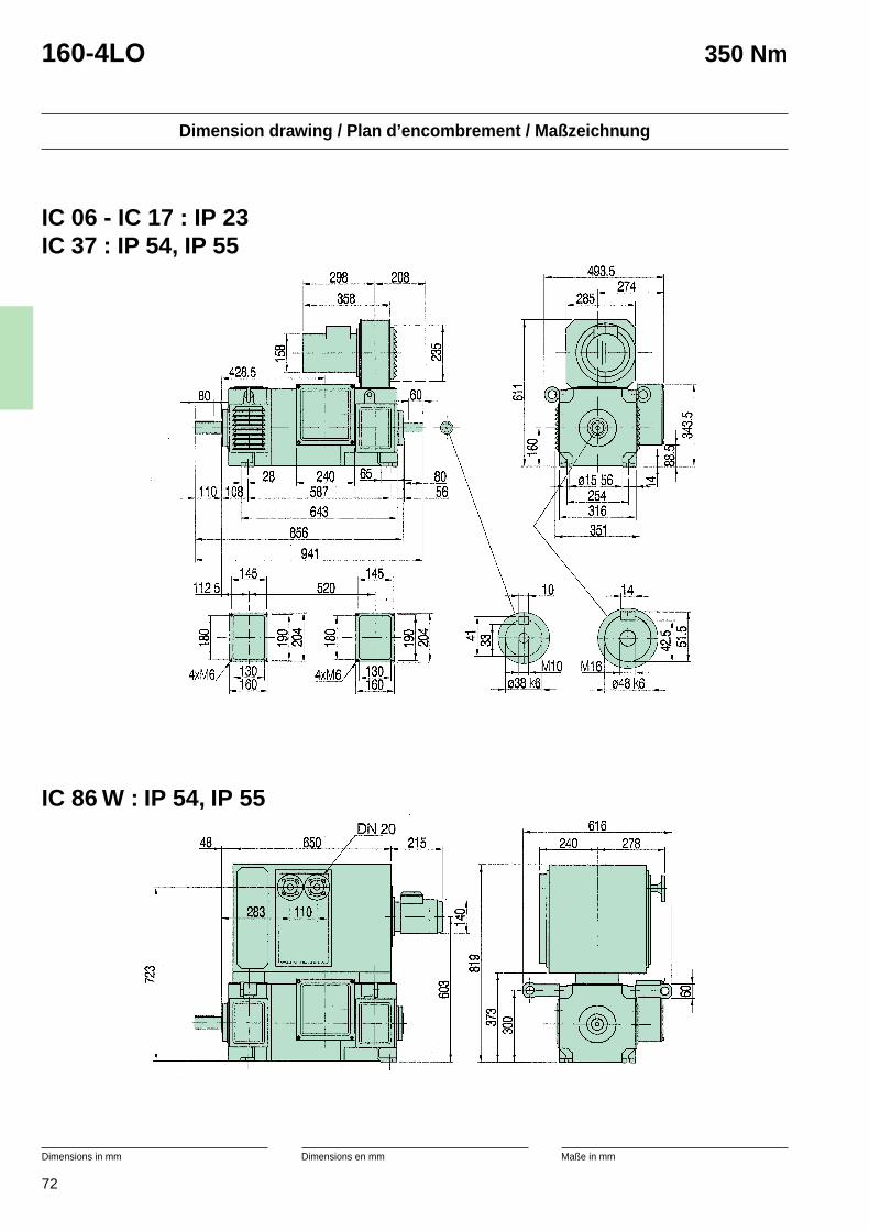
72
Dimension drawing / Plan d’encombrement / Maßzeichnung
Dimensions in mm Dimensions en mm Maße in mm
160-4LO 350 Nm
IC 86 W : IP 54, IP 55
IC 06 - IC 17 : IP 23IC 37 : IP 54, IP 55
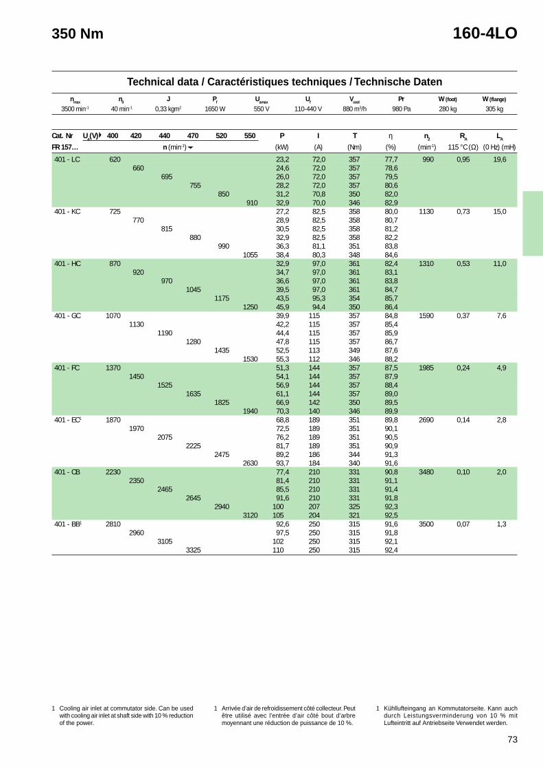
73
Technical data / Caractéristiques techniques / Technische Datennmax n0 J Pf Uamax Uf Vcool Pr W (foot) W (flange)
1 Cooling air inlet at commutator side. Can be usedwith cooling air inlet at shaft side with 10 % reductionof the power.
* Normally kept in stock with tropicalisation.See page 156.
1 Arrivée d’air de refroidissement côté collecteur. Peutêtre utilisé avec l’entrée d’air côté bout d’arbremoyennant une réduction de puissance de 10 %.
* Normalement en stock et tropicalisés.Voir page 156.
1 Kühllufteingang an Kommutatorseite. Kann auchdurch Leistungsverminderung von 10 % mitLufteintritt auf Antriebseite Verwendet werden.
* Normal auf Lager und tropenfest.Siehe Seite 156.
350 Nm 160-4LO
3500 min-1 40 min-1 0,33 kgm2 1650 W 550 V 110-440 V 880 m3/h 980 Pa 280 kg 305 kg
Cat. Nr Ua(V) 400 420 440 470 520 550 P I T η n2 RA LA
FR 157… n (min-1) (kW) (A) (Nm) (%) (min-1) 115 °C (Ω) (0 Hz) (mH)
401 - LC 620 23,2 72,0 357 77,7 990 0,95 19,6660 24,6 72,0 357 78,6
695 26,0 72,0 357 79,5755 28,2 72,0 357 80,6
850 31,2 70,8 350 82,0910 32,9 70,0 346 82,9
401 - KC 725 27,2 82,5 358 80,0 1130 0,73 15,0770 28,9 82,5 358 80,7
815 30,5 82,5 358 81,2880 32,9 82,5 358 82,2
990 36,3 81,1 351 83,81055 38,4 80,3 348 84,6
401 - HC 870 32,9 97,0 361 82,4 1310 0,53 11,0920 34,7 97,0 361 83,1
970 36,6 97,0 361 83,81045 39,5 97,0 361 84,7
1175 43,5 95,3 354 85,71250 45,9 94,4 350 86,4
401 - GC 1070 39,9 115 357 84,8 1590 0,37 7,61130 42,2 115 357 85,4
1190 44,4 115 357 85,91280 47,8 115 357 86,7
1435 52,5 113 349 87,61530 55,3 112 346 88,2
401 - FC 1370 51,3 144 357 87,5 1985 0,24 4,91450 54,1 144 357 87,9
1525 56,9 144 357 88,41635 61,1 144 357 89,0
1825 66,9 142 350 89,51940 70,3 140 346 89,9
401 - EC1 1870 68,8 189 351 89,8 2690 0,14 2,81970 72,5 189 351 90,1
2075 76,2 189 351 90,52225 81,7 189 351 90,9
2475 89,2 186 344 91,32630 93,7 184 340 91,6
401 - CB 2230 77,4 210 331 90,8 3480 0,10 2,02350 81,4 210 331 91,1
2465 85,5 210 331 91,42645 91,6 210 331 91,8
2940 100 207 325 92,33120 105 204 321 92,5
401 - BB1 2810 92,6 250 315 91,6 3500 0,07 1,32960 97,5 250 315 91,8
3105 102 250 315 92,13325 110 250 315 92,4
1 Cooling air inlet at commutator side. Can be usedwith cooling air inlet at shaft side with 10 % reductionof the power.
1 Arrivée d’air de refroidissement côté collecteur. Peutêtre utilisé avec l’entrée d’air côté bout d’arbremoyennant une réduction de puissance de 10 %.
1 Kühllufteingang an Kommutatorseite. Kann auchdurch Leistungsverminderung von 10 % mitLufteintritt auf Antriebseite Verwendet werden.
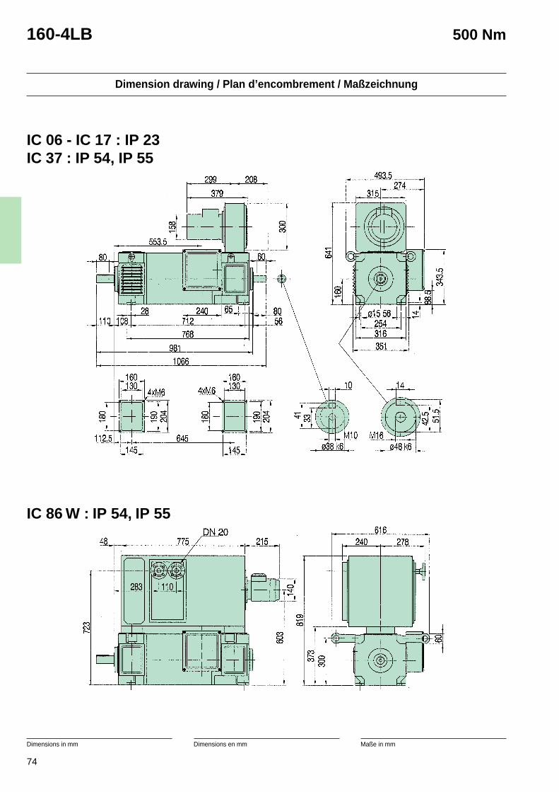
74
Dimension drawing / Plan d’encombrement / Maßzeichnung
Dimensions in mm Dimensions en mm Maße in mm
160-4LB 500 Nm
IC 86 W : IP 54, IP 55
IC 06 - IC 17 : IP 23IC 37 : IP 54, IP 55
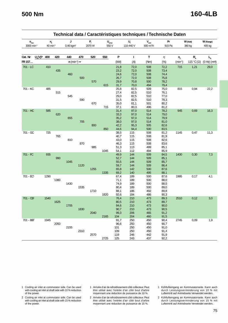
75
Technical data / Caractéristiques techniques / Technische Datennmax n0 J Pf Uamax Uf Vcool Pr W (foot) W (flange)
1 Cooling air inlet at commutator side. Can be usedwith cooling air inlet at shaft side with 10 % reductionof the power.
* Normally kept in stock with tropicalisation.See page 156.
1 Arrivée d’air de refroidissement côté collecteur. Peutêtre utilisé avec l’entrée d’air côté bout d’arbremoyennant une réduction de puissance de 10 %.
* Normalement en stock et tropicalisés.Voir page 156.
1 Kühllufteingang an Kommutatorseite. Kann auchdurch Leistungsverminderung von 10 % mitLufteintritt auf Antriebseite Verwendet werden.
* Normal auf Lager und tropenfest.Siehe Seite 156.
500 Nm 160-4LB
3000 min-1 40 min-1 0,46 kgm2 2070 W 550 V 110-440 V 600 m3/h 915 Pa 380 kg 405 kg
Cat. Nr Ua(V) 400 420 440 470 520 550 P I T η n2 RA LA
FR 157… n (min-1) (kW) (A) (Nm) (%) (min-1) 115 °C (Ω) (0 Hz) (mH)
701 - LC 410 21,8 72,0 508 72,2 715 1,21 29,0435 23,2 72,0 508 73,4
460 24,6 72,0 508 74,4500 26,7 72,0 508 75,8
570 29,9 70,8 500 78,2615 31,7 70,0 494 79,4
701 - KC 485 25,8 82,5 509 75,0 815 0,94 22,2515 27,4 82,5 510 76,1
545 29,0 82,5 510 77,0590 31,5 82,5 510 78,3
670 35,0 81,1 501 80,2715 37,1 80,3 496 81,2
701 - HC 585 31,4 97,0 514 78,2 945 0,69 16,3620 33,3 97,0 514 79,0
655 35,2 97,0 514 79,9705 38,0 97,0 514 81,0
800 42,2 95,3 505 82,6850 44,6 94,4 500 83,5
701 - GC 725 38,5 115 508 81,2 1145 0,47 11,3765 40,7 115 508 81,9
810 43,0 115 508 82,6870 46,3 115 508 83,6
985 51,3 113 499 85,11045 54,1 112 494 85,9
701 - FC 935 49,9 144 509 84,5 1430 0,30 7,3990 52,7 144 509 85,1
1045 55,5 144 509 85,71120 59,7 144 509 86,4
1255 65,8 142 500 87,61335 69,2 140 495 88,1
701 - EC1 1290 67,4 189 500 87,6 1995 0,17 4,11360 71,1 189 500 88,0
1430 74,9 189 500 88,51535 80,4 189 500 89,0
1710 88,1 186 492 89,81820 92,6 184 486 90,3
701 - CB1 1540 76,4 210 473 89,3 2510 0,12 3,01625 80,5 210 473 89,7
1705 84,6 210 473 90,01830 90,7 210 473 90,5
2040 99,3 206 465 91,22165 104 204 460 91,5
701 - BB2 1945 91,7 250 450 90,4 2745 0,09 1,92050 96,6 250 450 90,7
2155 101 250 450 91,02310 109 250 450 91,4
2570 119 246 442 91,92725 125 243 437 92,2
1 Cooling air inlet at commutator side. Can be usedwith cooling air inlet at shaft side with 10 % reductionof the power.
2 Cooling air inlet at commutator side. Can be usedwith cooling air inlet at shaft side with 15 % reductionof the power.
1 Arrivée d’air de refroidissement côté collecteur. Peutêtre utilisé avec l’entrée d’air côté bout d’arbremoyennant une réduction de puissance de 10 %.
2 Arrivée d’air de refroidissement côté collecteur. Peutêtre utilisé avec l’entrée d’air côté bout d’arbremoyennant une réduction de puissance de 15 %.
1 Kühllufteingang an Kommutatorseite. Kann auchdurch Leistungsverminderung von 10 % mitLufteintritt auf Antriebseite Verwendet werden.
2 Kühllufteingang an Kommutatorseite. Kann auchdurch Leistungsverminderung von 15 % mitLufteintritt auf Antriebseite Verwendet werden.
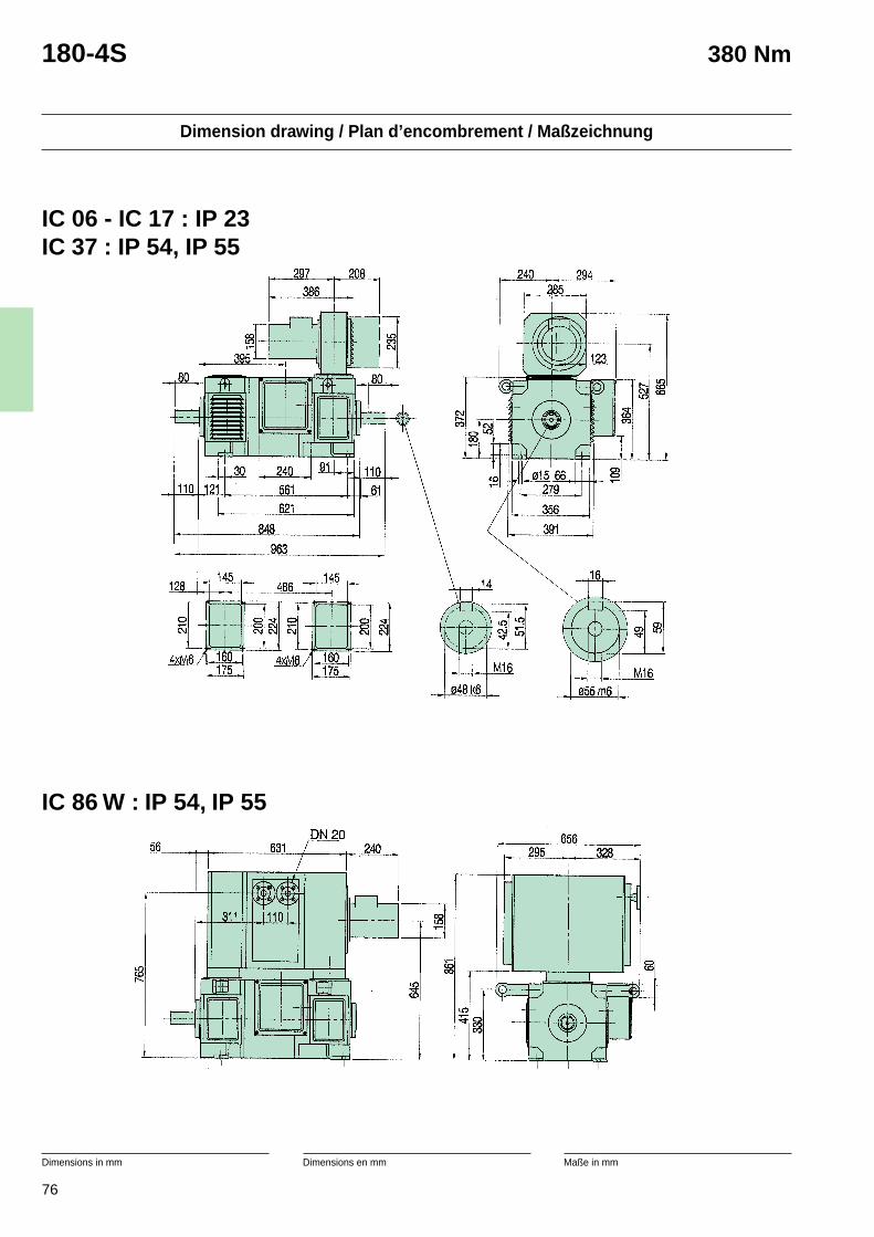
76
Dimension drawing / Plan d’encombrement / Maßzeichnung
Dimensions in mm Dimensions en mm Maße in mm
180-4S 380 Nm
IC 86 W : IP 54, IP 55
IC 06 - IC 17 : IP 23IC 37 : IP 54, IP 55
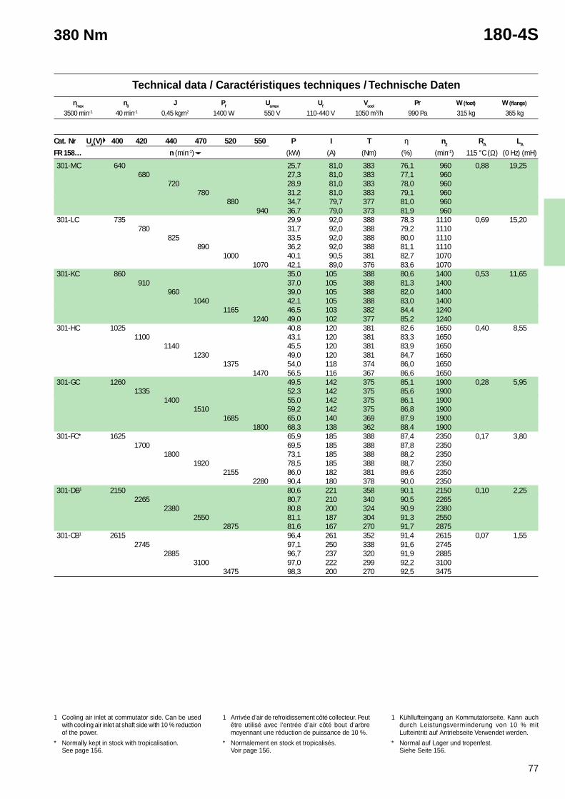
77
Technical data / Caractéristiques techniques / Technische Datennmax n0 J Pf Uamax Uf Vcool Pr W (foot) W (flange)
1 Cooling air inlet at commutator side. Can be usedwith cooling air inlet at shaft side with 10 % reductionof the power.
* Normally kept in stock with tropicalisation.See page 156.
1 Arrivée d’air de refroidissement côté collecteur. Peutêtre utilisé avec l’entrée d’air côté bout d’arbremoyennant une réduction de puissance de 10 %.
* Normalement en stock et tropicalisés.Voir page 156.
1 Kühllufteingang an Kommutatorseite. Kann auchdurch Leistungsverminderung von 10 % mitLufteintritt auf Antriebseite Verwendet werden.
* Normal auf Lager und tropenfest.Siehe Seite 156.
380 Nm 180-4S
Cat. Nr Ua(V) 400 420 440 470 520 550 P I T η n2 RA LA
FR 158… n (min-1) (kW) (A) (Nm) (%) (min-1) 115 °C (Ω) (0 Hz) (mH)
301-MC 640 25,7 81,0 383 76,1 960 0,88 19,25680 27,3 81,0 383 77,1 960
720 28,9 81,0 383 78,0 960780 31,2 81,0 383 79,1 960
880 34,7 79,7 377 81,0 960940 36,7 79,0 373 81,9 960
301-LC 735 29,9 92,0 388 78,3 1110 0,69 15,20780 31,7 92,0 388 79,2 1110
825 33,5 92,0 388 80,0 1110890 36,2 92,0 388 81,1 1110
1000 40,1 90,5 381 82,7 10701070 42,1 89,0 376 83,6 1070
301-KC 860 35,0 105 388 80,6 1400 0,53 11,65910 37,0 105 388 81,3 1400
960 39,0 105 388 82,0 14001040 42,1 105 388 83,0 1400
1165 46,5 103 382 84,4 12401240 49,0 102 377 85,2 1240
301-HC 1025 40,8 120 381 82,6 1650 0,40 8,551100 43,1 120 381 83,3 1650
1140 45,5 120 381 83,9 16501230 49,0 120 381 84,7 1650
1375 54,0 118 374 86,0 16501470 56,5 116 367 86,6 1650
301-GC 1260 49,5 142 375 85,1 1900 0,28 5,951335 52,3 142 375 85,6 1900
1400 55,0 142 375 86,1 19001510 59,2 142 375 86,8 1900
1685 65,0 140 369 87,9 19001800 68,3 138 362 88,4 1900
301-FC* 1625 65,9 185 388 87,4 2350 0,17 3,801700 69,5 185 388 87,8 2350
1800 73,1 185 388 88,2 23501920 78,5 185 388 88,7 2350
2155 86,0 182 381 89,6 23502280 90,4 180 378 90,0 2350
301-DB1 2150 80,6 221 358 90,1 2150 0,10 2,252265 80,7 210 340 90,5 2265
2380 80,8 200 324 90,9 23802550 81,1 187 304 91,3 2550
2875 81,6 167 270 91,7 2875301-CB1 2615 96,4 261 352 91,4 2615 0,07 1,55
2745 97,1 250 338 91,6 27452885 96,7 237 320 91,9 2885
3100 97,0 222 299 92,2 31003475 98,3 200 270 92,5 3475
3500 min-1 40 min-1 0,45 kgm2 1400 W 550 V 110-440 V 1050 m3/h 990 Pa 315 kg 365 kg
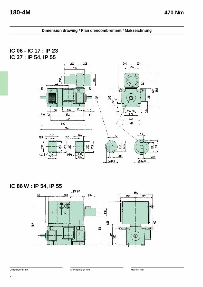
78
Dimension drawing / Plan d’encombrement / Maßzeichnung
Dimensions in mm Dimensions en mm Maße in mm
180-4M 470 Nm
IC 86 W : IP 54, IP 55
IC 06 - IC 17 : IP 23IC 37 : IP 54, IP 55
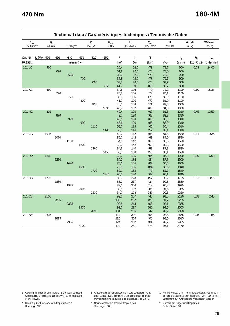
79
Technical data / Caractéristiques techniques / Technische Datennmax n0 J Pf Uamax Uf Vcool Pr W (foot) W (flange)
1 Cooling air inlet at commutator side. Can be usedwith cooling air inlet at shaft side with 10 % reductionof the power.
* Normally kept in stock with tropicalisation.See page 156.
1 Arrivée d’air de refroidissement côté collecteur. Peutêtre utilisé avec l’entrée d’air côté bout d’arbremoyennant une réduction de puissance de 10 %.
* Normalement en stock et tropicalisés.Voir page 156.
1 Kühllufteingang an Kommutatorseite. Kann auchdurch Leistungsverminderung von 10 % mitLufteintritt auf Antriebseite Verwendet werden.
* Normal auf Lager und tropenfest.Siehe Seite 156.
470 Nm 180-4M
3500 min-1 40 min-1 0,53 kgm2 1550 W 550 V 110-440 V 1050 m3/h 990 Pa 365 kg 395 kg
Cat. Nr Ua(V) 400 420 440 470 520 550 P I T η n2 RA LA
FR 158… n (min-1) (kW) (A) (Nm) (%) (min-1) 115 °C (Ω) (0 Hz) (mH)
201-LC 590 29,4 92,0 478 76,7 900 0,78 24,00620 31,2 92,0 478 77,5 900
660 33,0 92,0 478 78,6 900710 35,8 92,0 478 79,7 900
805 39,7 90,5 470 81,7 860860 41,7 89,0 463 82,7 860
201-KC 690 34,5 105 479 79,2 1100 0,60 18,35730 36,5 105 479 80,1 1100
770 38,6 105 479 80,9 1100830 41,7 105 479 81,9 1100
935 46,2 103 471 83,6 10001000 48,7 102 466 84,5 1000
201-HC 825 40,4 120 468 81,5 1310 0,45 13,50870 42,7 120 468 82,3 1310
920 45,1 120 468 83,0 1310990 48,6 120 468 83,9 1310
1115 53,7 118 460 85,4 13101190 56,3 116 452 86,1 1310
201-GC 1015 49,2 142 463 84,3 1520 0,31 9,351070 52,0 142 463 84,9 1520
1130 54,8 142 463 85,5 15201220 59,0 142 463 86,3 1520
1360 64,9 140 455 87,5 15201450 68,3 138 450 88,1 1520
201-FC* 1295 65,7 185 484 87,0 1900 0,19 6,001370 69,0 185 484 87,5 1900
1440 73,0 185 484 88,0 19001550 78,1 185 484 88,6 1840
1730 86,1 182 476 89,6 18401840 90,5 180 469 90,1 1840
201-DB1 1735 83,0 228 457 90,2 1735 0,12 3,551830 83,2 217 434 90,3 1830
1925 83,2 206 413 90,8 19252065 83,5 192 386 91,5 2065
2330 84,7 173 347 90,5 2330201-CB1 2120 99,0 267 446 91,5 2120 0,08 2,45
2225 100 257 429 91,7 22252335 99,8 244 408 92,1 2335
2505 99,7 227 380 92,5 25052820 101 205 342 92,9 2820
201-BB1 2675 114 307 408 92,3 2675 0,05 1,552815 120 305 408 92,5 2815
2955 124 302 401 92,7 29553170 124 281 373 93,1 3170
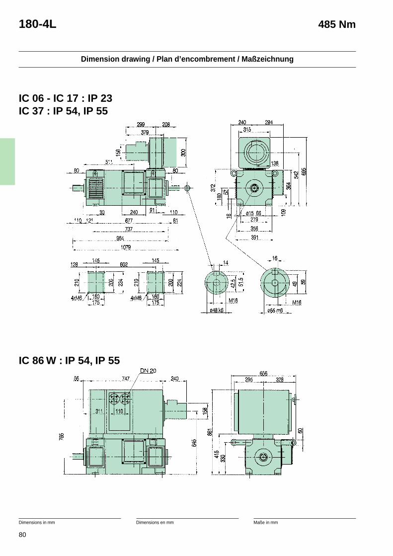
80
Dimension drawing / Plan d’encombrement / Maßzeichnung
Dimensions in mm Dimensions en mm Maße in mm
180-4L 485 Nm
IC 06 - IC 17 : IP 23IC 37 : IP 54, IP 55
IC 86 W : IP 54, IP 55
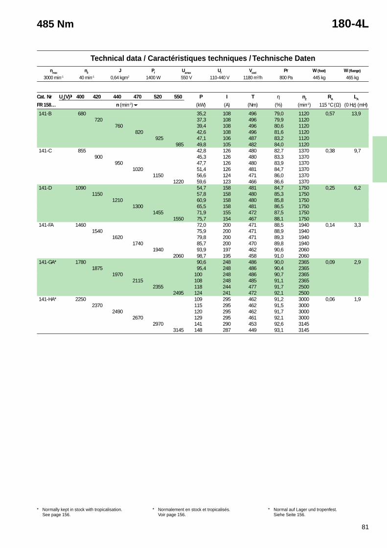
81
Technical data / Caractéristiques techniques / Technische Datennmax n0 J Pf Uamax Uf Vcool Pr W (foot) W (flange)
1 Cooling air inlet at commutator side. Can be usedwith cooling air inlet at shaft side with 10 % reductionof the power.
* Normally kept in stock with tropicalisation.See page 156.
1 Arrivée d’air de refroidissement côté collecteur. Peutêtre utilisé avec l’entrée d’air côté bout d’arbremoyennant une réduction de puissance de 10 %.
* Normalement en stock et tropicalisés.Voir page 156.
1 Kühllufteingang an Kommutatorseite. Kann auchdurch Leistungsverminderung von 10 % mitLufteintritt auf Antriebseite Verwendet werden.
* Normal auf Lager und tropenfest.Siehe Seite 156.
485 Nm 180-4L
Cat. Nr Ua(V) 400 420 440 470 520 550 P I T η n2 RA LA
FR 158… n (min-1) (kW) (A) (Nm) (%) (min-1) 115 °C (Ω) (0 Hz) (mH)
141-B 680 35,2 108 496 79,0 1120 0,57 13,9720 37,3 108 496 79,9 1120
760 39,4 108 496 80,6 1120820 42,6 108 496 81,6 1120
925 47,1 106 487 83,2 1120985 49,8 105 482 84,0 1120
141-C 855 42,8 126 480 82,7 1370 0,38 9,7900 45,3 126 480 83,3 1370
950 47,7 126 480 83,9 13701020 51,4 126 481 84,7 1370
1150 56,6 124 471 86,0 13701220 59,6 123 466 86,6 1370
141-D 1090 54,7 158 481 84,7 1750 0,25 6,21150 57,8 158 480 85,3 1750
1210 60,9 158 480 85,8 17501300 65,5 158 481 86,5 1750
1455 71,9 155 472 87,5 17501550 75,7 154 467 88,1 1750
141-FA 1460 72,0 200 471 88,5 1940 0,14 3,31540 75,9 200 471 88,9 1940
1620 79,8 200 471 89,3 19401740 85,7 200 470 89,8 1940
1940 93,9 197 462 90,6 20602060 98,7 195 458 91,0 2060
141-GA* 1780 90,6 248 486 90,0 2365 0,09 2,91875 95,4 248 486 90,4 2365
1970 100 248 486 90,7 23652115 108 248 485 91,1 2365
2355 118 244 477 91,7 25002495 124 241 472 92,1 2500
141-HA* 2250 109 295 462 91,2 3000 0,06 1,92370 115 295 462 91,5 3000
2490 120 295 462 91,7 30002670 129 295 461 92,1 3000
2970 141 290 453 92,6 31453145 148 287 449 93,1 3145
3000 min-1 40 min-1 0,64 kgm2 1400 W 550 V 110-440 V 1180 m3/h 800 Pa 445 kg 465 kg
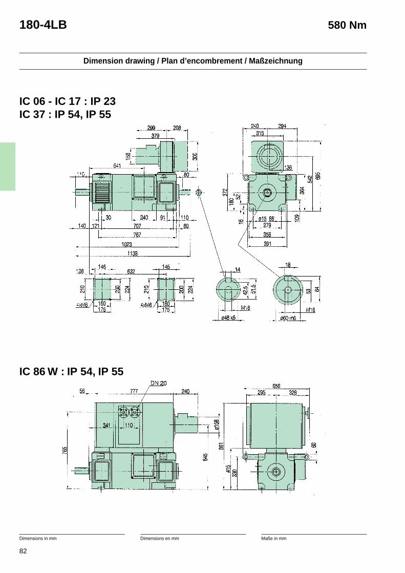
82
Dimension drawing / Plan d’encombrement / Maßzeichnung
Dimensions in mm Dimensions en mm Maße in mm
180-4LB 580 Nm
IC 06 - IC 17 : IP 23IC 37 : IP 54, IP 55
IC 86 W : IP 54, IP 55
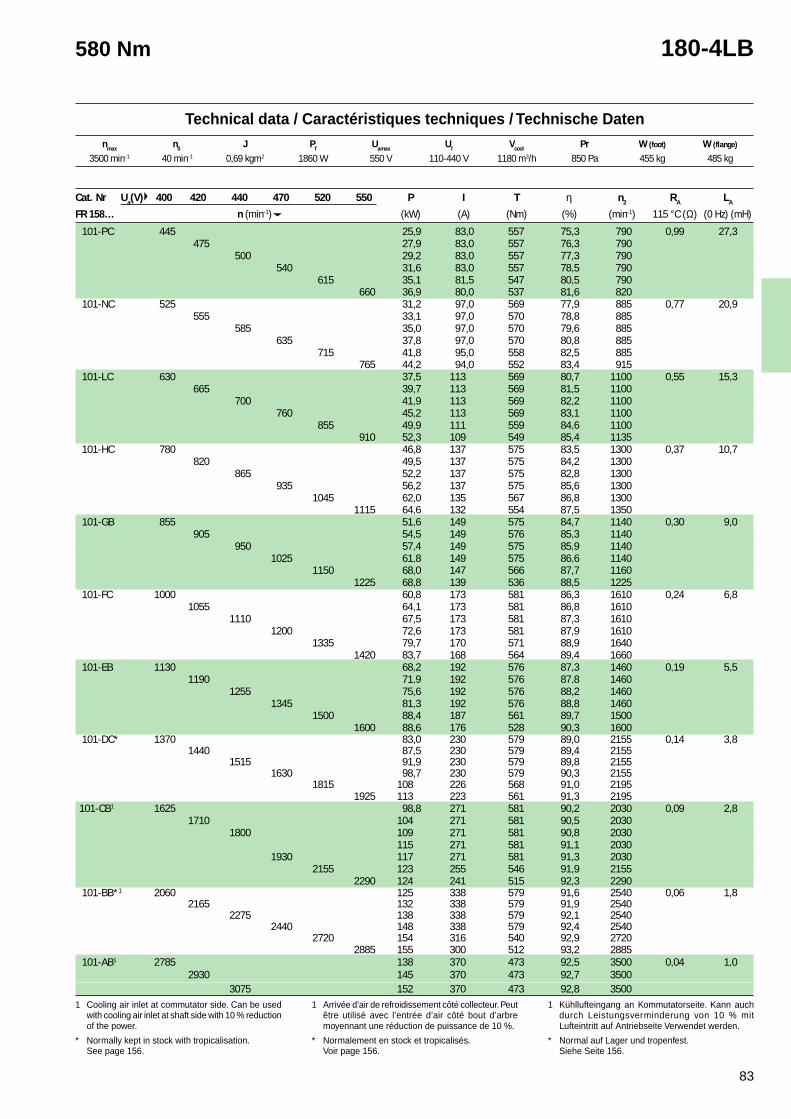
83
Technical data / Caractéristiques techniques / Technische Datennmax n0 J Pf Uamax Uf Vcool Pr W (foot) W (flange)
1 Cooling air inlet at commutator side. Can be usedwith cooling air inlet at shaft side with 10 % reductionof the power.
* Normally kept in stock with tropicalisation.See page 156.
1 Arrivée d’air de refroidissement côté collecteur. Peutêtre utilisé avec l’entrée d’air côté bout d’arbremoyennant une réduction de puissance de 10 %.
* Normalement en stock et tropicalisés.Voir page 156.
1 Kühllufteingang an Kommutatorseite. Kann auchdurch Leistungsverminderung von 10 % mitLufteintritt auf Antriebseite Verwendet werden.
* Normal auf Lager und tropenfest.Siehe Seite 156.
580 Nm 180-4LB
3500 min-1 40 min-1 0,69 kgm2 1860 W 550 V 110-440 V 1180 m3/h 850 Pa 455 kg 485 kg
Cat. Nr Ua(V) 400 420 440 470 520 550 P I T η n2 RA LA
FR 158… n (min-1) (kW) (A) (Nm) (%) (min-1) 115 °C (Ω) (0 Hz) (mH)
101-PC 445 25,9 83,0 557 75,3 790 0,99 27,3475 27,9 83,0 557 76,3 790
500 29,2 83,0 557 77,3 790540 31,6 83,0 557 78,5 790
615 35,1 81,5 547 80,5 790660 36,9 80,0 537 81,6 820
101-NC 525 31,2 97,0 569 77,9 885 0,77 20,9555 33,1 97,0 570 78,8 885
585 35,0 97,0 570 79,6 885635 37,8 97,0 570 80,8 885
715 41,8 95,0 558 82,5 885765 44,2 94,0 552 83,4 915
101-LC 630 37,5 113 569 80,7 1100 0,55 15,3665 39,7 113 569 81,5 1100
700 41,9 113 569 82,2 1100760 45,2 113 569 83,1 1100
855 49,9 111 559 84,6 1100910 52,3 109 549 85,4 1135
101-HC 780 46,8 137 575 83,5 1300 0,37 10,7820 49,5 137 575 84,2 1300
865 52,2 137 575 82,8 1300935 56,2 137 575 85,6 1300
1045 62,0 135 567 86,8 13001115 64,6 132 554 87,5 1350
101-GB 855 51,6 149 575 84,7 1140 0,30 9,0905 54,5 149 576 85,3 1140
950 57,4 149 575 85,9 11401025 61,8 149 575 86,6 1140
1150 68,0 147 566 87,7 11601225 68,8 139 536 88,5 1225
101-FC 1000 60,8 173 581 86,3 1610 0,24 6,81055 64,1 173 581 86,8 1610
1110 67,5 173 581 87,3 16101200 72,6 173 581 87,9 1610
1335 79,7 170 571 88,9 16401420 83,7 168 564 89,4 1660
101-EB 1130 68,2 192 576 87,3 1460 0,19 5,51190 71,9 192 576 87,8 1460
1255 75,6 192 576 88,2 14601345 81,3 192 576 88,8 1460
1500 88,4 187 561 89,7 15001600 88,6 176 528 90,3 1600
101-DC* 1370 83,0 230 579 89,0 2155 0,14 3,81440 87,5 230 579 89,4 2155
1515 91,9 230 579 89,8 21551630 98,7 230 579 90,3 2155
1815 108 226 568 91,0 21951925 113 223 561 91,3 2195
101-CB1 1625 98,8 271 581 90,2 2030 0,09 2,81710 104 271 581 90,5 2030
1800 109 271 581 90,8 2030115 271 581 91,1 2030
1930 117 271 581 91,3 20302155 123 255 546 91,9 2155
2290 124 241 515 92,3 2290 101-BB*1 2060 125 338 579 91,6 2540 0,06 1,8
2165 132 338 579 91,9 25402275 138 338 579 92,1 2540
2440 148 338 579 92,4 25402720 154 316 540 92,9 2720
2885 155 300 512 93,2 2885 101-AB1 2785 138 370 473 92,5 3500 0,04 1,0
2930 145 370 473 92,7 35003075 152 370 473 92,8 3500
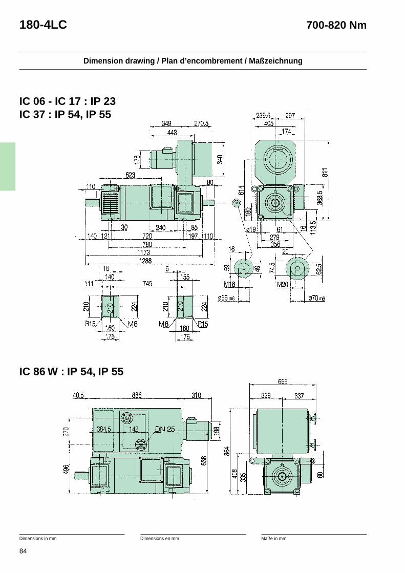
84
Dimension drawing / Plan d’encombrement / Maßzeichnung
Dimensions in mm Dimensions en mm Maße in mm
180-4LC 700-820 Nm
IC 06 - IC 17 : IP 23IC 37 : IP 54, IP 55
IC 86 W : IP 54, IP 55
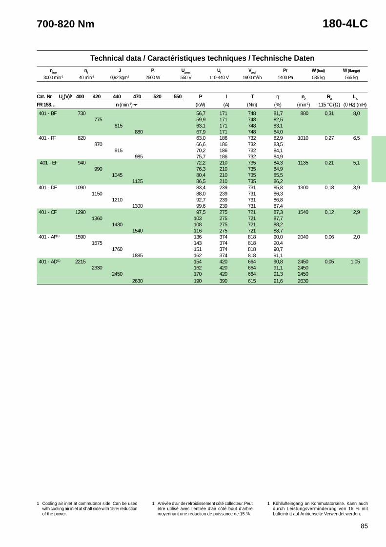
85
Technical data / Caractéristiques techniques / Technische Datennmax n0 J Pf Uamax Uf Vcool Pr W (foot) W (flange)
1 Cooling air inlet at commutator side. Can be usedwith cooling air inlet at shaft side with 10 % reductionof the power.
* Normally kept in stock with tropicalisation.See page 156.
1 Arrivée d’air de refroidissement côté collecteur. Peutêtre utilisé avec l’entrée d’air côté bout d’arbremoyennant une réduction de puissance de 10 %.
* Normalement en stock et tropicalisés.Voir page 156.
1 Kühllufteingang an Kommutatorseite. Kann auchdurch Leistungsverminderung von 10 % mitLufteintritt auf Antriebseite Verwendet werden.
* Normal auf Lager und tropenfest.Siehe Seite 156.
700-820 Nm 180-4LC
3000 min-1 40 min-1 0,92 kgm2 2500 W 550 V 110-440 V 1900 m3/h 1400 Pa 535 kg 565 kg
Cat. Nr Ua(V) 400 420 440 470 520 550 P I T η n2 RA LA
FR 158… n (min-1) (kW) (A) (Nm) (%) (min-1) 115 °C (Ω) (0 Hz) (mH)
401 - BF 730 56,7 171 748 81,7 880 0,31 8,0775 59,9 171 748 82,5
815 63,1 171 748 83,1880 67,9 171 748 84,0
401 - FF 820 63,0 186 732 82,9 1010 0,27 6,5870 66,6 186 732 83,5
915 70,2 186 732 84,1985 75,7 186 732 84,9
401 - EF 940 72,2 210 735 84,3 1135 0,21 5,1990 76,3 210 735 84,9
1045 80,4 210 735 85,51125 86,5 210 735 86,2
401 - DF 1090 83,4 239 731 85,8 1300 0,18 3,91150 88,0 239 731 86,3
1210 92,7 239 731 86,81300 99,6 239 731 87,4
401 - CF 1290 97,5 275 721 87,3 1540 0,12 2,91360 103 275 721 87,7
1430 108 275 721 88,21540 116 275 721 88,7
401 - AF(1) 1590 136 374 818 90,0 2040 0,06 2,01675 143 374 818 90,4
1760 151 374 818 90,71885 162 374 818 91,1
401 - AD(1) 2215 154 420 664 90,8 2450 0,05 1,052330 162 420 664 91,1 2450
2450 170 420 664 91,3 24502630 190 390 615 91,6 2630
1 Cooling air inlet at commutator side. Can be usedwith cooling air inlet at shaft side with 15 % reductionof the power.
1 Arrivée d’air de refroidissement côté collecteur. Peutêtre utilisé avec l’entrée d’air côté bout d’arbremoyennant une réduction de puissance de 15 %.
1 Kühllufteingang an Kommutatorseite. Kann auchdurch Leistungsverminderung von 15 % mitLufteintritt auf Antriebseite Verwendet werden.
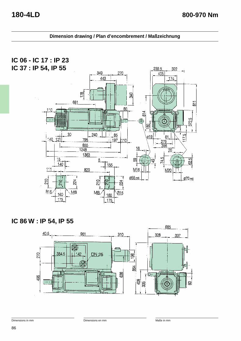
86
Dimension drawing / Plan d’encombrement / Maßzeichnung
Dimensions in mm Dimensions en mm Maße in mm
180-4LD 800-970 Nm
IC 06 - IC 17 : IP 23IC 37 : IP 54, IP 55
IC 86 W : IP 54, IP 55
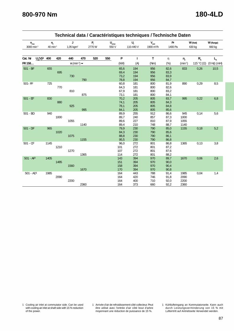
87
Technical data / Caractéristiques techniques / Technische Datennmax n0 J Pf Uamax Uf Vcool Pr W (foot) W (flange)
1 Cooling air inlet at commutator side. Can be usedwith cooling air inlet at shaft side with 10 % reductionof the power.
* Normally kept in stock with tropicalisation.See page 156.
1 Arrivée d’air de refroidissement côté collecteur. Peutêtre utilisé avec l’entrée d’air côté bout d’arbremoyennant une réduction de puissance de 10 %.
* Normalement en stock et tropicalisés.Voir page 156.
1 Kühllufteingang an Kommutatorseite. Kann auchdurch Leistungsverminderung von 10 % mitLufteintritt auf Antriebseite Verwendet werden.
* Normal auf Lager und tropenfest.Siehe Seite 156.
800-970 Nm 180-4LD
3000 min-1 40 min-1 1,05 kgm2 2770 W 550 V 110-440 V 1900 m3/h 1400 Pa 630 kg 660 kg
Cat. Nr Ua(V) 400 420 440 470 520 550 P I T η n2 RA LA
FR 158… n (min-1) (kW) (A) (Nm) (%) (min-1) 115 °C (Ω) (0 Hz) (mH)
501 - BF 655 65,6 194 956 82,6 833 0,26 10,5695 69,4 194 956 83,3
730 73,2 194 956 83,9790 78,8 194 956 84,7
501- FF 725 60,8 181 800 81,9 890 0,29 8,5770 64,3 181 800 82,6
810 67,9 181 800 83,2875 73,1 181 800 84,1
501 - EF 830 70,2 205 805 83,7 995 0,22 6,8880 74,1 205 805 84,3
925 78,1 205 805 84,8995 84,1 205 805 85,6
501 - BD 940 89,9 255 912 86,6 945 0,14 5,61000 89,7 240 857 87,3 1000
1055 89,6 227 810 87,9 10551140 89,4 210 748 88,7 1140
501 - DF 965 79,9 230 790 85,0 1155 0,18 5,21020 84,3 230 790 85,6
1075 88,8 230 790 86,11155 95,5 230 790 86,8
501 - CF 1145 96,0 272 801 86,8 1365 0,13 3,81210 101 272 801 87,2
1270 107 272 801 87,61365 114 272 801 88,2
501 - AF1 1405 143 394 970 89,7 1670 0,06 2,61485 151 394 970 90,0
1560 158 394 970 90,41670 170 394 970 90,8
501 - AD1 1985 164 443 788 91,4 1985 0,04 1,42090 164 420 746 91,8 2090
2200 164 400 710 92,0 22002360 164 373 660 92,2 2360
1 Cooling air inlet at commutator side. Can be usedwith cooling air inlet at shaft side with 15 % reductionof the power.
1 Arrivée d’air de refroidissement côté collecteur. Peutêtre utilisé avec l’entrée d’air côté bout d’arbremoyennant une réduction de puissance de 15 %.
1 Kühllufteingang an Kommutatorseite. Kann auchdurch Leistungsverminderung von 15 % mitLufteirtritt auf Antriebseite Verwendet werden.
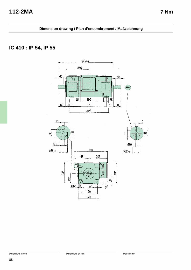
88
Dimension drawing / Plan d’encombrement / Maßzeichnung
Dimensions in mm Dimensions en mm Maße in mm
112-2MA 7 Nm
IC 410 : IP 54, IP 55
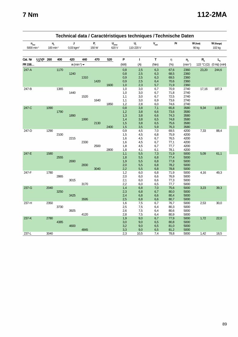
89
2 With exchanger tube.(10% power reduction without it).IC 610
2 Avec un tube échangeur.(réduction de puissance de 10 % sans le tube).IC 610
2 Mit Kühlungsrohr.(Ohne, 10% Leistungsreduktion).IC610
Technical data / Caractéristiques techniques / Technische Datennmax n0 J Pf Uamax Uf Vcool Pr W (foot) W (flange)
7 Nm 112-2MA
Cat. Nr Ua(V) 260 400 420 440 470 520 P I T η n2 RA LA
FR 158… n (min-1) (kW) (A) (Nm) (%) (min-1) 115 °C (Ω) (0 Hz) (mH)
247-A 1170 0,8 2,5 6,3 67,6 2360 23,20 244,61240 0,8 2,5 6,3 68,5 2360
1310 0,9 2,5 6,3 69,5 23601420 0,9 2,5 6,4 70,6 2360
1600 1,0 2,3 5,7 71,9 2360247-B 1365 1,0 3,0 6,7 70,9 2740 17,16 187,3
1440 1,0 3,0 6,7 71,8 27401520 1,1 3,0 6,7 72,5 2740
1640 1,1 3,0 6,9 73,6 27401850 1,2 2,8 6,0 74,6 2740
247-C 1090 0,8 3,8 7,1 65,8 3580 9,34 119,91790 1,2 3,8 6,6 73,6 3580
1890 1,3 3,8 6,6 74,3 35801990 1,4 3,8 6,5 74,8 3580
2130 1,5 3,8 6,5 75,6 35802400 1,5 3,5 5,9 76,3 3580
247-D 1290 0,9 4,5 7,0 69,5 4200 7,33 88,42100 1,5 4,5 6,8 75,9 4200
2215 1,6 4,5 6,7 76,5 42002330 1,6 4,5 6,7 77,1 4200
2500 1,8 4,5 6,7 77,7 42002800 1,8 4,1 6,1 78,1 4200
247-E 1580 1,1 5,5 7,3 71,9 5000 5,09 61,12555 1,8 5,5 6,8 77,4 5000
2690 1,9 5,5 6,8 77,8 50002830 2,0 5,5 6,8 78,2 5000
3040 2,2 5,5 6,8 78,8 5000247-F 1780 1,2 6,0 6,8 71,9 5000 4,16 49,3
2865 2,0 6,0 6,6 76,9 50003015 2,1 6,0 6,6 77,3 5000
3170 2,2 6,0 6,5 77,7 5000237-G 2040 1,4 6,8 7,0 75,6 5000 3,23 39,3
3250 2,3 6,8 6,7 80,0 50003425 2,4 6,8 6,6 80,4 5000
3595 2,5 6,8 6,6 80,7 5000237-H 2350 1,6 7,5 6,7 76,7 5000 2,53 30,0
3730 2,5 7,5 6,4 80,3 50003925 2,6 7,5 6,4 80,6 5000
4120 2,8 7,5 6,4 80,9 5000237-K 2780 1,9 9,0 6,7 77,9 5000 1,72 22,0
4385 3,0 9,0 6,5 80,8 50004600 3,2 9,0 6,5 81,0 5000
4845 3,3 9,0 6,5 81,2 5000237-L 3040 2,3 10,5 7,4 78,8 5000 1,42 18,5
5000 min-1 100 min-1 0,03 kgm2 150 W 620 V 110-220 V 90 kg 102 kg
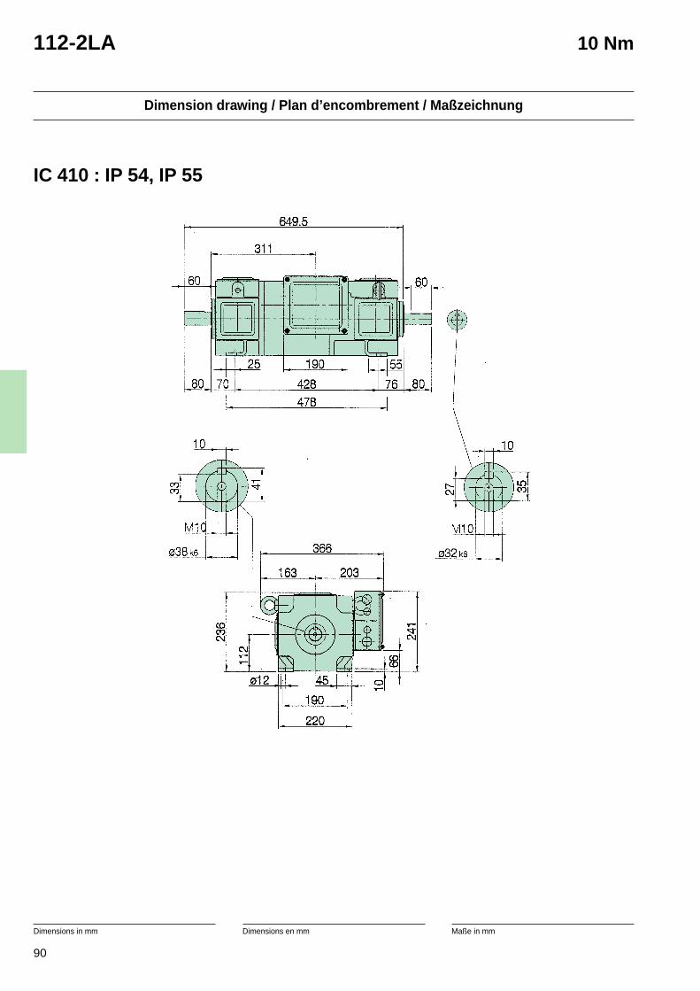
90
Dimension drawing / Plan d’encombrement / Maßzeichnung
Dimensions in mm Dimensions en mm Maße in mm
112-2LA 10 Nm
IC 410 : IP 54, IP 55
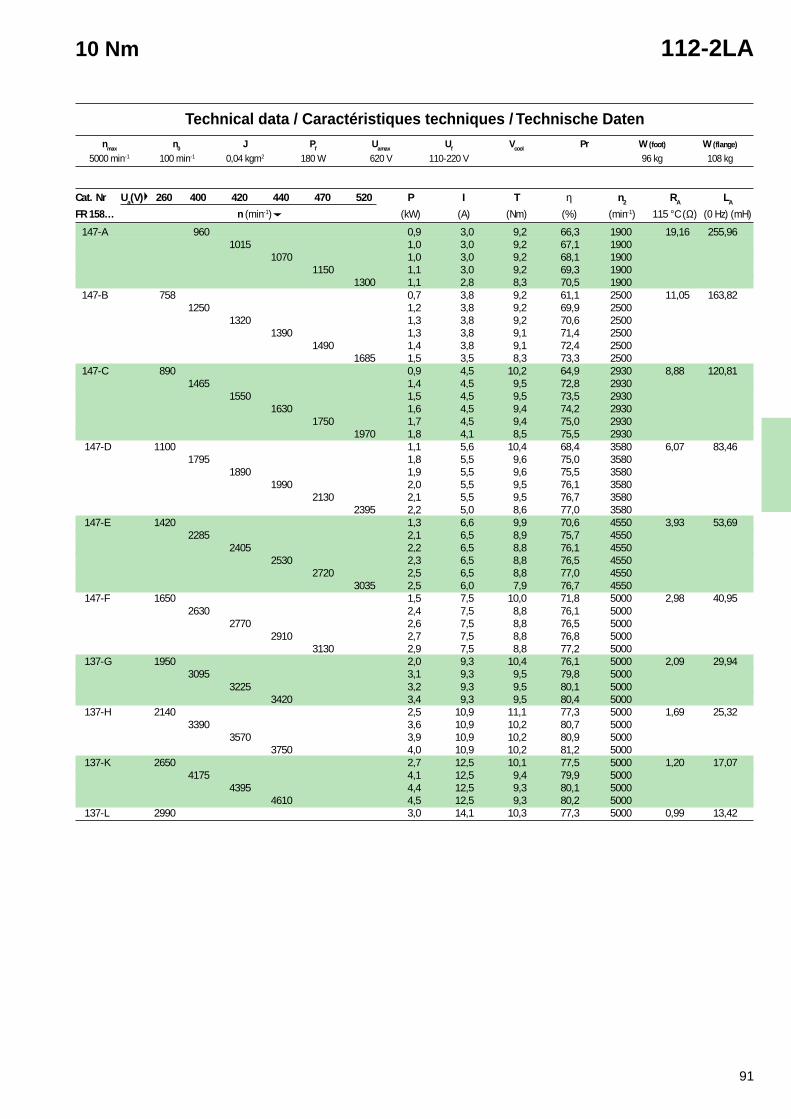
91
2 With exchanger tube.(10% power reduction without it).IC 610
2 Avec un tube échangeur.(réduction de puissance de 10 % sans le tube).IC 610
2 Mit Kühlungsrohr.(Ohne, 10% Leistungsreduktion).IC610
Technical data / Caractéristiques techniques / Technische Datennmax n0 J Pf Uamax Uf Vcool Pr W (foot) W (flange)
10 Nm 112-2LA
Cat. Nr Ua(V) 260 400 420 440 470 520 P I T η n2 RA LA
FR 158… n (min-1) (kW) (A) (Nm) (%) (min-1) 115 °C (Ω) (0 Hz) (mH)
147-A 960 0,9 3,0 9,2 66,3 1900 19,16 255,961015 1,0 3,0 9,2 67,1 1900
1070 1,0 3,0 9,2 68,1 19001150 1,1 3,0 9,2 69,3 1900
1300 1,1 2,8 8,3 70,5 1900 147-B 758 0,7 3,8 9,2 61,1 2500 11,05 163,82
1250 1,2 3,8 9,2 69,9 25001320 1,3 3,8 9,2 70,6 2500
1390 1,3 3,8 9,1 71,4 25001490 1,4 3,8 9,1 72,4 2500
1685 1,5 3,5 8,3 73,3 2500 147-C 890 0,9 4,5 10,2 64,9 2930 8,88 120,81
1465 1,4 4,5 9,5 72,8 29301550 1,5 4,5 9,5 73,5 2930
1630 1,6 4,5 9,4 74,2 29301750 1,7 4,5 9,4 75,0 2930
1970 1,8 4,1 8,5 75,5 2930 147-D 1100 1,1 5,6 10,4 68,4 3580 6,07 83,46
1795 1,8 5,5 9,6 75,0 35801890 1,9 5,5 9,6 75,5 3580
1990 2,0 5,5 9,5 76,1 35802130 2,1 5,5 9,5 76,7 3580
2395 2,2 5,0 8,6 77,0 3580 147-E 1420 1,3 6,6 9,9 70,6 4550 3,93 53,69
2285 2,1 6,5 8,9 75,7 45502405 2,2 6,5 8,8 76,1 4550
2530 2,3 6,5 8,8 76,5 45502720 2,5 6,5 8,8 77,0 4550
3035 2,5 6,0 7,9 76,7 4550 147-F 1650 1,5 7,5 10,0 71,8 5000 2,98 40,95
2630 2,4 7,5 8,8 76,1 50002770 2,6 7,5 8,8 76,5 5000
2910 2,7 7,5 8,8 76,8 50003130 2,9 7,5 8,8 77,2 5000
137-G 1950 2,0 9,3 10,4 76,1 5000 2,09 29,943095 3,1 9,3 9,5 79,8 5000
3225 3,2 9,3 9,5 80,1 50003420 3,4 9,3 9,5 80,4 5000
137-H 2140 2,5 10,9 11,1 77,3 5000 1,69 25,323390 3,6 10,9 10,2 80,7 5000
3570 3,9 10,9 10,2 80,9 50003750 4,0 10,9 10,2 81,2 5000
137-K 2650 2,7 12,5 10,1 77,5 5000 1,20 17,074175 4,1 12,5 9,4 79,9 5000
4395 4,4 12,5 9,3 80,1 50004610 4,5 12,5 9,3 80,2 5000
137-L 2990 3,0 14,1 10,3 77,3 5000 0,99 13,42
5000 min-1 100 min-1 0,04 kgm2 180 W 620 V 110-220 V 96 kg 108 kg

92
Dimension drawing / Plan d’encombrement / Maßzeichnung
Dimensions in mm Dimensions en mm Maße in mm
132-2M 13 Nm
IC 410 : IP 54, IP 55
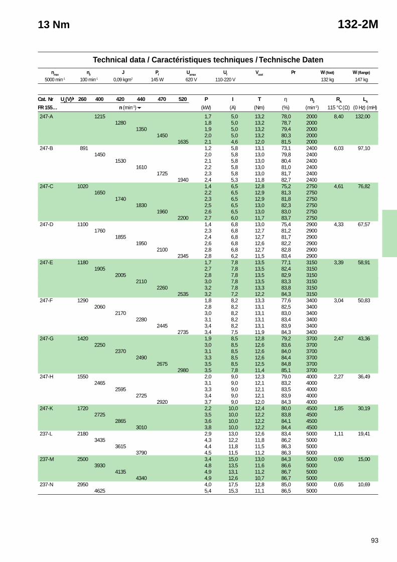
93
2 With exchanger tube.(10% power reduction without it).IC 610
2 Avec un tube échangeur.(réduction de puissance de 10 % sans le tube).IC 610
2 Mit Kühlungsrohr.(Ohne, 10% Leistungsreduktion).IC610
Technical data / Caractéristiques techniques / Technische Datennmax n0 J Pf Uamax Uf Vcool Pr W (foot) W (flange)
13 Nm 132-2M
Cat. Nr Ua(V) 260 400 420 440 470 520 P I T η n2 RA LA
FR 155… n (min-1) (kW) (A) (Nm) (%) (min-1) 115 °C (Ω) (0 Hz) (mH)
247-A 1215 1,7 5,0 13,2 78,0 2000 8,40 132,001280 1,8 5,0 13,2 78,7 2000
1350 1,9 5,0 13,2 79,4 20001450 2,0 5,0 13,2 80,3 2000
1635 2,1 4,6 12,0 81,5 2000247-B 891 1,2 5,8 13,1 73,1 2400 6,03 97,10
1450 2,0 5,8 13,0 79,8 24001530 2,1 5,8 13,0 80,4 2400
1610 2,2 5,8 13,0 81,0 24001725 2,3 5,8 13,0 81,7 2400
1940 2,4 5,3 11,8 82,7 2400247-C 1020 1,4 6,5 12,8 75,2 2750 4,61 76,82
1650 2,2 6,5 12,9 81,3 27501740 2,3 6,5 12,9 81,8 2750
1830 2,5 6,5 13,0 82,3 27501960 2,6 6,5 13,0 83,0 2750
2200 2,7 6,0 11,7 83,7 2750247-D 1100 1,4 6,8 13,0 75,4 2900 4,33 67,57
1760 2,3 6,8 12,7 81,2 29001855 2,4 6,8 12,7 81,7 2900
1950 2,6 6,8 12,6 82,2 29002100 2,8 6,8 12,7 82,8 2900
2345 2,8 6,2 11,5 83,4 2900247-E 1180 1,7 7,8 13,5 77,1 3150 3,39 58,91
1905 2,7 7,8 13,5 82,4 31502005 2,8 7,8 13,5 82,9 3150
2110 3,0 7,8 13,5 83,3 31502260 3,2 7,8 13,3 83,8 3150
2535 3,2 7,2 12,2 84,3 3150247-F 1290 1,8 8,2 13,3 77,6 3400 3,04 50,83
2060 2,8 8,2 13,1 82,5 34002170 3,0 8,2 13,1 83,0 3400
2280 3,1 8,2 13,1 83,4 34002445 3,4 8,2 13,1 83,9 3400
2735 3,4 7,5 11,9 84,3 3400247-G 1420 1,9 8,5 12,8 79,2 3700 2,47 43,36
2250 3,0 8,5 12,6 83,6 37002370 3,1 8,5 12,6 84,0 3700
2490 3,3 8,5 12,6 84,4 37002675 3,5 8,5 12,5 84,8 3700
2980 3,5 7,8 11,4 85,1 3700247-H 1550 2,0 9,0 12,3 79,0 4000 2,27 36,49
2465 3,1 9,0 12,1 83,2 40002595 3,3 9,0 12,1 83,5 4000
2725 3,4 9,0 12,1 83,9 40002920 3,7 9,0 12,0 84,3 4000
247-K 1720 2,2 10,0 12,4 80,0 4500 1,85 30,192725 3,5 10,0 12,2 83,8 4500
2865 3,6 10,0 12,2 84,1 45003010 3,8 10,0 12,2 84,4 4500
237-L 2180 2,9 13,0 12,6 83,4 5000 1,11 19,413435 4,3 12,2 11,8 86,2 5000
3615 4,4 11,8 11,5 86,3 50003790 4,5 11,5 11,2 86,3 5000
237-M 2500 3,4 15,0 13,0 84,3 5000 0,90 15,003930 4,8 13,5 11,6 86,6 5000
4135 4,9 13,1 11,2 86,7 50004340 4,9 12,6 10,7 86,7 5000
237-N 2950 4,0 17,5 12,8 85,0 5000 0,65 10,694625 5,4 15,3 11,1 86,5 5000
5000 min-1 100 min-1 0,09 kgm2 145 W 620 V 110-220 V 132 kg 147 kg
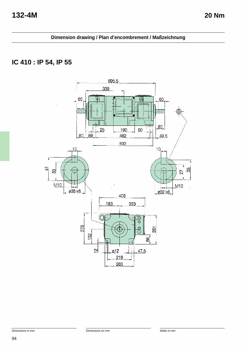
94
Dimension drawing / Plan d’encombrement / Maßzeichnung
Dimensions in mm Dimensions en mm Maße in mm
132-4M 20 Nm
IC 410 : IP 54, IP 55
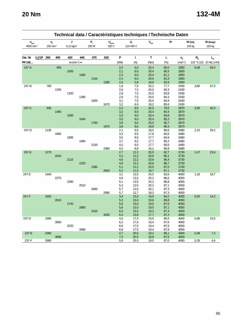
95
2 With exchanger tube.(10% power reduction without it).IC 610
2 Avec un tube échangeur.(réduction de puissance de 10 % sans le tube).IC 610
2 Mit Kühlungsrohr.(Ohne, 10% Leistungsreduktion).IC610
Technical data / Caractéristiques techniques / Technische Datennmax n0 J Pf Uamax Uf Vcool Pr W (foot) W (flange)
20 Nm 132-4M
Cat. Nr Ua(V) 260 400 420 440 470 520 P I T η n2 RA LA
FR 156… n (min-1) (kW) (A) (Nm) (%) (min-1) 115 °C (Ω) (0 Hz) (mH)
247-A 955 2,0 6,0 20,4 80,0 1850 6,08 94,01005 2,1 6,0 20,4 80,5 1850
1060 2,3 6,0 20,4 81,1 18501140 2,4 6,0 20,5 81,9 1850
1280 2,5 5,8 18,6 82,8 1850 247-B 780 1,6 7,5 20,2 77,7 2430 3,80 57,0
1255 2,6 7,5 20,0 83,3 24301320 2,8 7,5 20,0 83,8 2430
1390 2,9 7,5 20,0 84,3 24301500 3,1 7,5 20,0 84,9 2430
1670 3,2 6,9 18,2 85,6 2430 247-C 930 2,0 9,0 20,5 79,5 2870 2,83 42,0
1480 3,2 9,0 20,4 84,4 28701560 3,3 9,0 20,4 84,8 2870
1640 3,5 9,0 20,4 85,2 28701760 3,8 9,0 20,5 85,7 2870
1970 3,8 8,6 18,6 86,3 2870 247-D 1135 2,1 9,5 18,0 80,6 3480 2,10 29,2
1800 3,3 9,5 17,8 84,6 34801895 3,5 9,5 17,7 84,9 3480
1990 3,7 9,5 17,7 85,2 34802130 4,0 9,5 17,7 85,6 3480
2380 4,0 8,8 16,1 85,8 3480 257-E 1270 2,7 12,2 20,5 82,7 3730 1,47 23,6
2010 4,3 12,2 20,6 86,1 37302115 4,6 12,2 20,6 86,4 3730
2220 4,8 12,2 20,6 86,7 37302380 5,1 12,2 20,5 87,0 3730
2650 5,2 11,5 18,7 87,1 3730247-E 1440 3,1 13,5 20,5 83,6 4000 1,18 18,7
2270 4,8 13,5 20,2 86,6 40002390 5,1 13,5 20,2 86,8 4000
2510 5,3 13,5 20,2 87,1 40002690 5,7 13,5 20,1 87,3 4000
2995 5,7 12,7 18,3 87,3 4000247-F 1655 3,4 15,0 19,9 84,2 4000 0,93 14,2
2610 5,3 15,0 19,6 86,8 40002745 5,6 15,0 19,5 87,0 4000
2880 5,9 15,0 19,5 87,1 40003100 6,3 15,0 19,3 87,4 4000
3430 6,4 13,8 17,7 87,2 4000237-D 1950 4,0 17,5 19,5 85,5 4000 0,68 10,5
3060 6,2 17,5 19,4 87,6 40003220 6,6 17,5 19,4 87,6 4000
3380 6,8 17,5 19,4 87,9 4000 237-E 2360 4,7 20,5 19,2 86,1 4000 0,48 7,3
3690 7,3 20,5 18,8 87,6 4000 237-F 2980 5,9 25,5 19,0 87,0 4000 0,29 4,6
4000 min-1 100 min-1 0,12 kgm2 150 W 620 V 110-440 V 145 kg 160 kg
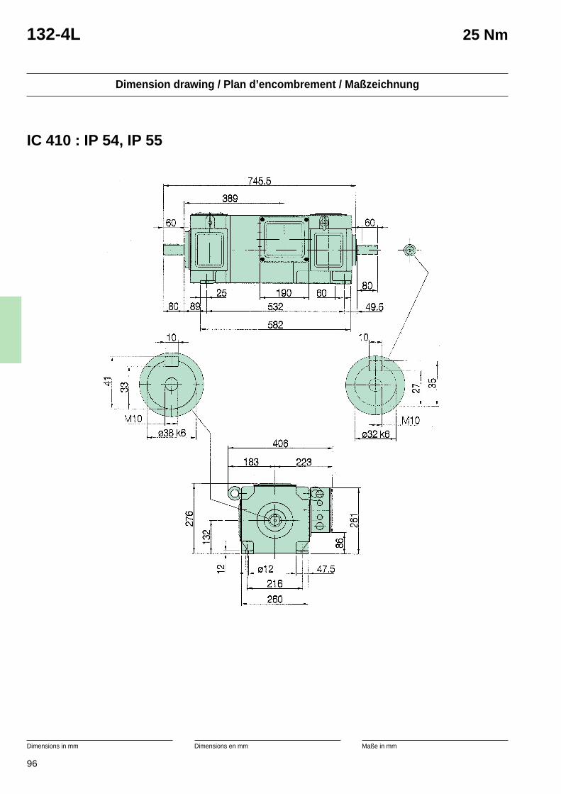
96
Dimension drawing / Plan d’encombrement / Maßzeichnung
Dimensions in mm Dimensions en mm Maße in mm
132-4L 25 Nm
IC 410 : IP 54, IP 55
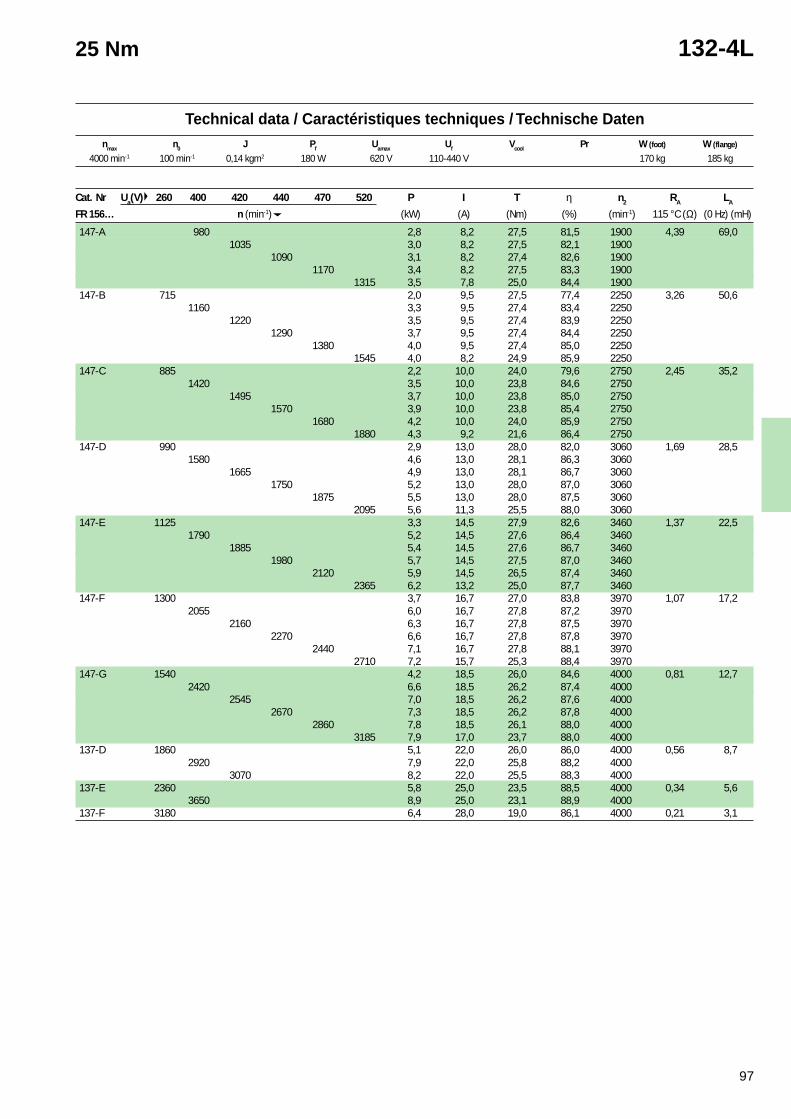
97
2 With exchanger tube.(10% power reduction without it).IC 610
2 Avec un tube échangeur.(réduction de puissance de 10 % sans le tube).IC 610
2 Mit Kühlungsrohr.(Ohne, 10% Leistungsreduktion).IC610
Technical data / Caractéristiques techniques / Technische Datennmax n0 J Pf Uamax Uf Vcool Pr W (foot) W (flange)
25 Nm 132-4L
Cat. Nr Ua(V) 260 400 420 440 470 520 P I T η n2 RA LA
FR 156… n (min-1) (kW) (A) (Nm) (%) (min-1) 115 °C (Ω) (0 Hz) (mH)
147-A 980 2,8 8,2 27,5 81,5 1900 4,39 69,01035 3,0 8,2 27,5 82,1 1900
1090 3,1 8,2 27,4 82,6 19001170 3,4 8,2 27,5 83,3 1900
1315 3,5 7,8 25,0 84,4 1900147-B 715 2,0 9,5 27,5 77,4 2250 3,26 50,6
1160 3,3 9,5 27,4 83,4 22501220 3,5 9,5 27,4 83,9 2250
1290 3,7 9,5 27,4 84,4 22501380 4,0 9,5 27,4 85,0 2250
1545 4,0 8,2 24,9 85,9 2250147-C 885 2,2 10,0 24,0 79,6 2750 2,45 35,2
1420 3,5 10,0 23,8 84,6 27501495 3,7 10,0 23,8 85,0 2750
1570 3,9 10,0 23,8 85,4 27501680 4,2 10,0 24,0 85,9 2750
1880 4,3 9,2 21,6 86,4 2750147-D 990 2,9 13,0 28,0 82,0 3060 1,69 28,5
1580 4,6 13,0 28,1 86,3 30601665 4,9 13,0 28,1 86,7 3060
1750 5,2 13,0 28,0 87,0 30601875 5,5 13,0 28,0 87,5 3060
2095 5,6 11,3 25,5 88,0 3060147-E 1125 3,3 14,5 27,9 82,6 3460 1,37 22,5
1790 5,2 14,5 27,6 86,4 34601885 5,4 14,5 27,6 86,7 3460
1980 5,7 14,5 27,5 87,0 34602120 5,9 14,5 26,5 87,4 3460
2365 6,2 13,2 25,0 87,7 3460147-F 1300 3,7 16,7 27,0 83,8 3970 1,07 17,2
2055 6,0 16,7 27,8 87,2 39702160 6,3 16,7 27,8 87,5 3970
2270 6,6 16,7 27,8 87,8 39702440 7,1 16,7 27,8 88,1 3970
2710 7,2 15,7 25,3 88,4 3970147-G 1540 4,2 18,5 26,0 84,6 4000 0,81 12,7
2420 6,6 18,5 26,2 87,4 40002545 7,0 18,5 26,2 87,6 4000
2670 7,3 18,5 26,2 87,8 40002860 7,8 18,5 26,1 88,0 4000
3185 7,9 17,0 23,7 88,0 4000137-D 1860 5,1 22,0 26,0 86,0 4000 0,56 8,7
2920 7,9 22,0 25,8 88,2 40003070 8,2 22,0 25,5 88,3 4000
137-E 2360 5,8 25,0 23,5 88,5 4000 0,34 5,63650 8,9 25,0 23,1 88,9 4000
137-F 3180 6,4 28,0 19,0 86,1 4000 0,21 3,1
4000 min-1 100 min-1 0,14 kgm2 180 W 620 V 110-440 V 170 kg 185 kg
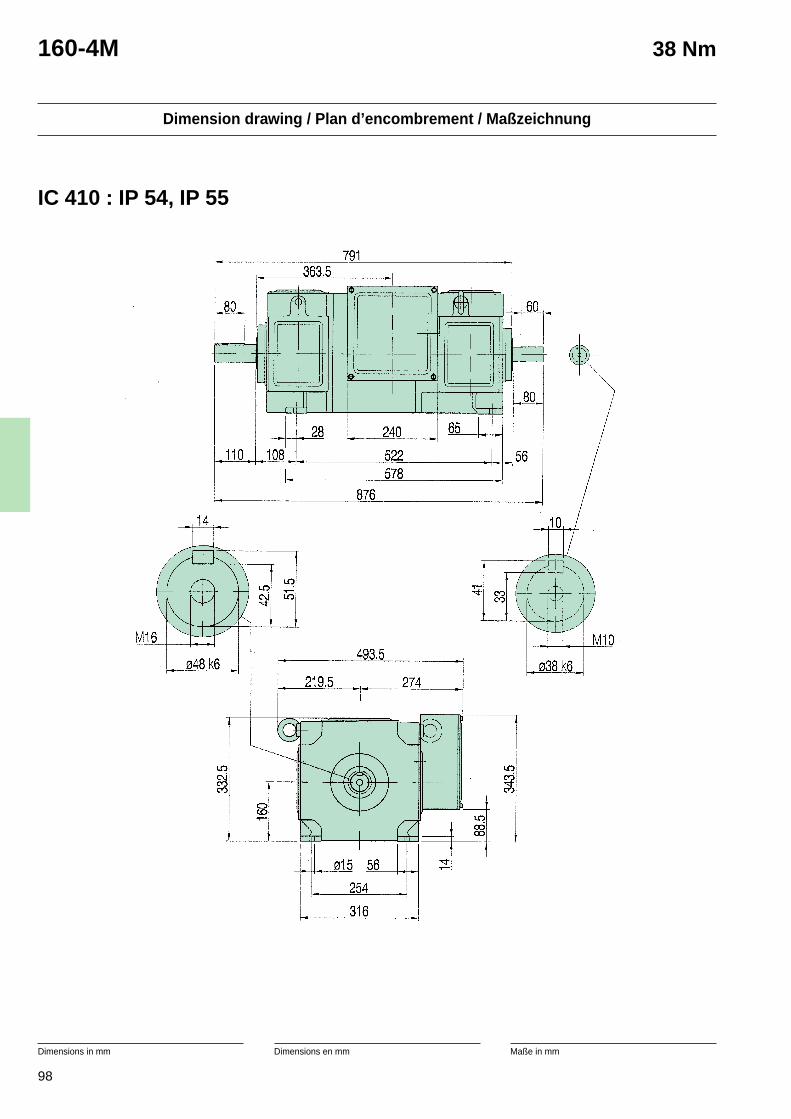
98
Dimension drawing / Plan d’encombrement / Maßzeichnung
Dimensions in mm Dimensions en mm Maße in mm
160-4M 38 Nm
IC 410 : IP 54, IP 55
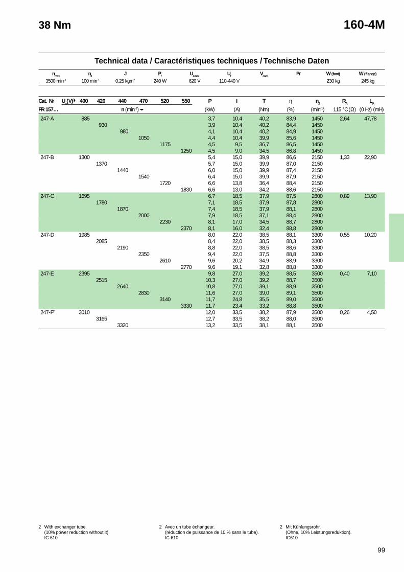
99
2 With exchanger tube.(10% power reduction without it).IC 610
2 Avec un tube échangeur.(réduction de puissance de 10 % sans le tube).IC 610
2 Mit Kühlungsrohr.(Ohne, 10% Leistungsreduktion).IC610
Technical data / Caractéristiques techniques / Technische Datennmax n0 J Pf Uamax Uf Vcool Pr W (foot) W (flange)
38 Nm 160-4M
Cat. Nr Ua(V) 400 420 440 470 520 550 P I T η n2 RA LA
FR 157… n (min-1) (kW) (A) (Nm) (%) (min-1) 115 °C (Ω) (0 Hz) (mH)
247-A 885 3,7 10,4 40,2 83,9 1450 2,64 47,78930 3,9 10,4 40,2 84,4 1450
980 4,1 10,4 40,2 84,9 14501050 4,4 10,4 39,9 85,6 1450
1175 4,5 9,5 36,7 86,5 14501250 4,5 9,0 34,5 86,8 1450
247-B 1300 5,4 15,0 39,9 86,6 2150 1,33 22,901370 5,7 15,0 39,9 87,0 2150
1440 6,0 15,0 39,9 87,4 21501540 6,4 15,0 39,9 87,9 2150
1720 6,6 13,8 36,4 88,4 21501830 6,6 13,0 34,2 88,6 2150
247-C 1695 6,7 18,5 37,9 87,5 2800 0,89 13,901780 7,1 18,5 37,9 87,8 2800
1870 7,4 18,5 37,9 88,1 28002000 7,9 18,5 37,1 88,4 2800
2230 8,1 17,0 34,5 88,7 28002370 8,1 16,0 32,4 88,8 2800
247-D 1985 8,0 22,0 38,5 88,1 3300 0,55 10,202085 8,4 22,0 38,5 88,3 3300
2190 8,8 22,0 38,5 88,6 33002350 9,4 22,0 37,5 88,8 3300
2610 9,6 20,2 34,9 88,9 33002770 9,6 19,1 32,8 88,8 3300
247-E 2395 9,8 27,0 39,2 88,5 3500 0,40 7,102515 10,3 27,0 39,2 88,7 3500
2640 10,8 27,0 39,1 88,9 35002830 11,6 27,0 39,0 89,1 3500
3140 11,7 24,8 35,5 89,0 35003330 11,7 23,4 33,2 88,8 3500
247-F2 3010 12,0 33,5 38,2 87,9 3500 0,26 4,503165 12,7 33,5 38,2 88,0 3500
3320 13,2 33,5 38,1 88,1 3500
3500 min-1 100 min-1 0,25 kgm2 240 W 620 V 110-440 V 230 kg 245 kg
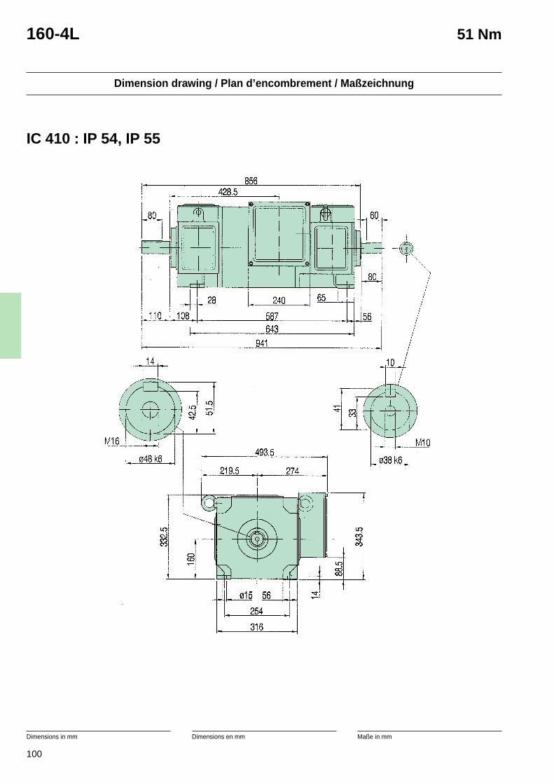
100
Dimension drawing / Plan d’encombrement / Maßzeichnung
Dimensions in mm Dimensions en mm Maße in mm
160-4L 51 Nm
IC 410 : IP 54, IP 55
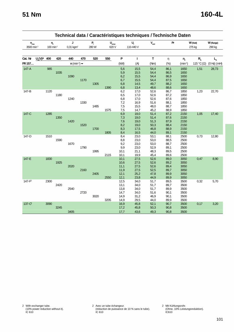
101
2 With exchanger tube.(10% power reduction without it).IC 610
2 Avec un tube échangeur.(réduction de puissance de 10 % sans le tube).IC 610
2 Mit Kühlungsrohr.(Ohne, 10% Leistungsreduktion).IC610
Technical data / Caractéristiques techniques / Technische Datennmax n0 J Pf Uamax Uf Vcool Pr W (foot) W (flange)
51 Nm 160-4L
Cat. Nr Ua(V) 400 420 440 470 520 550 P I T η n2 RA LA
FR 157… n (min-1) (kW) (A) (Nm) (%) (min-1) 115 °C (Ω) (0 Hz) (mH)
147-A 985 5,6 15,5 54,4 86,1 1650 1,51 28,731035 5,9 15,5 54,4 86,5 1650
1090 6,2 15,5 54,4 86,9 16501170 6,7 15,5 54,4 87,5 1650
1305 6,8 14,5 49,7 88,2 16501390 6,8 13,4 48,6 88,6 1650
147-B 1120 6,2 17,0 52,6 86,7 1850 1,23 22,701180 6,5 17,0 52,6 87,2 1850
1240 6,8 17,0 52,6 87,6 18501330 7,2 16,9 51,6 88,1 1850
1485 7,5 15,5 48,0 88,7 18501575 7,5 14,7 45,2 88,9 1850
147-C 1285 6,9 19,0 51,4 87,2 2150 1,05 17,401350 7,3 19,0 51,4 87,6 2150
1420 7,6 19,0 51,3 87,9 21501520 8,2 19,0 50,3 88,4 2150
1700 8,3 17,5 46,8 88,9 21501805 8,4 16,5 44,0 89,1 2150
147-D 1510 8,4 23,0 53,1 88,1 2500 0,73 12,801590 8,8 23,0 53,0 88,5 2500
1670 9,2 23,0 53,0 88,7 25001790 9,9 23,0 52,9 89,1 2500
1995 10,1 21,1 48,3 89,5 25002115 10,1 19,9 45,4 89,6 2500
147-E 1830 10,1 27,5 52,6 89,0 3050 0,47 8,901925 10,6 27,5 52,6 89,2 3050
2020 11,1 27,5 52,6 89,4 30502160 11,9 27,5 52,5 89,7 3050
2405 12,1 25,2 47,8 89,9 30502550 12,1 23,8 44,9 89,9 3050
147-F2 2300 12,5 34,0 51,7 89,5 3500 0,32 5,702420 13,1 34,0 51,7 89,7 3500
2540 13,8 34,0 51,7 89,9 35002720 14,7 34,0 51,6 90,1 3500
3020 14,9 31,2 46,9 90,1 35003205 14,9 29,5 44,0 89,9 3500
137-C2 3090 16,9 45,8 52,1 90,7 3500 0,17 3,203245 17,2 45,8 50,3 90,8 3500
3405 17,7 43,6 49,3 90,8 3500
3500 min-1 100 min-1 0,31 kgm2 280 W 620 V 110-440 V 275 kg 290 kg
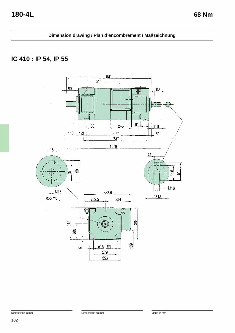
102
Dimension drawing / Plan d’encombrement / Maßzeichnung
Dimensions in mm Dimensions en mm Maße in mm
180-4L 68 Nm
IC 410 : IP 54, IP 55
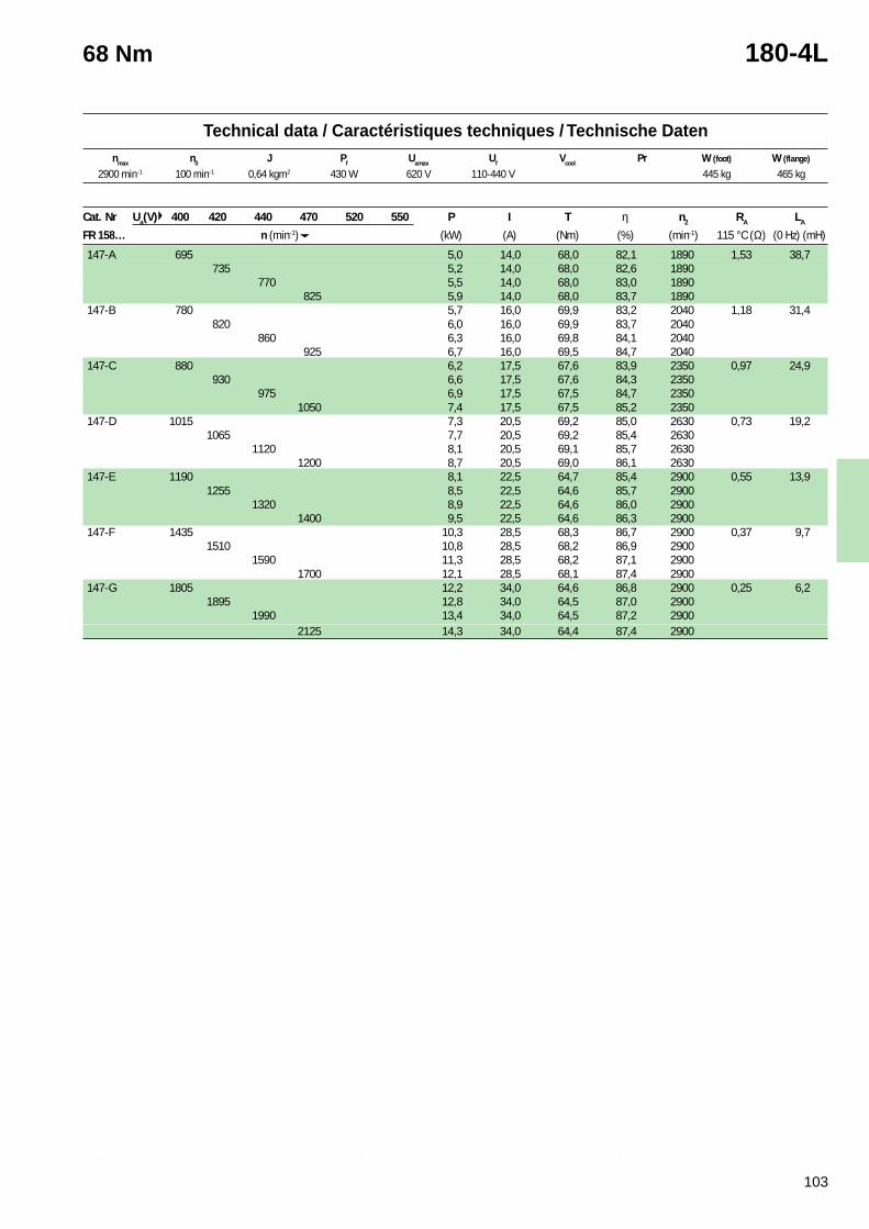
103
2 With exchanger tube.(10% power reduction without it).IC 610
2 Avec un tube échangeur.(réduction de puissance de 10 % sans le tube).IC 610
2 Mit Kühlungsrohr.(Ohne, 10% Leistungsreduktion).IC610
Technical data / Caractéristiques techniques / Technische Datennmax n0 J Pf Uamax Uf Vcool Pr W (foot) W (flange)
68 Nm 180-4L
Cat. Nr Ua(V) 400 420 440 470 520 550 P I T η n2 RA LA
FR 158… n (min-1) (kW) (A) (Nm) (%) (min-1) 115 °C (Ω) (0 Hz) (mH)
147-A 695 5,0 14,0 68,0 82,1 1890 1,53 38,7735 5,2 14,0 68,0 82,6 1890
770 5,5 14,0 68,0 83,0 1890825 5,9 14,0 68,0 83,7 1890
147-B 780 5,7 16,0 69,9 83,2 2040 1,18 31,4820 6,0 16,0 69,9 83,7 2040
860 6,3 16,0 69,8 84,1 2040925 6,7 16,0 69,5 84,7 2040
147-C 880 6,2 17,5 67,6 83,9 2350 0,97 24,9930 6,6 17,5 67,6 84,3 2350
975 6,9 17,5 67,5 84,7 23501050 7,4 17,5 67,5 85,2 2350
147-D 1015 7,3 20,5 69,2 85,0 2630 0,73 19,21065 7,7 20,5 69,2 85,4 2630
1120 8,1 20,5 69,1 85,7 26301200 8,7 20,5 69,0 86,1 2630
147-E 1190 8,1 22,5 64,7 85,4 2900 0,55 13,91255 8,5 22,5 64,6 85,7 2900
1320 8,9 22,5 64,6 86,0 29001400 9,5 22,5 64,6 86,3 2900
147-F 1435 10,3 28,5 68,3 86,7 2900 0,37 9,71510 10,8 28,5 68,2 86,9 2900
1590 11,3 28,5 68,2 87,1 29001700 12,1 28,5 68,1 87,4 2900
147-G 1805 12,2 34,0 64,6 86,8 2900 0,25 6,21895 12,8 34,0 64,5 87,0 2900
1990 13,4 34,0 64,5 87,2 29002125 14,3 34,0 64,4 87,4 2900
2900 min-1 100 min-1 0,64 kgm2 430 W 620 V 110-440 V 445 kg 465 kg
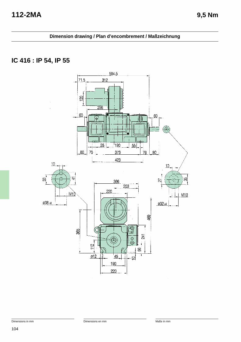
104
Dimension drawing / Plan d’encombrement / Maßzeichnung
Dimensions in mm Dimensions en mm Maße in mm
112-2MA 9,5 Nm
IC 416 : IP 54, IP 55
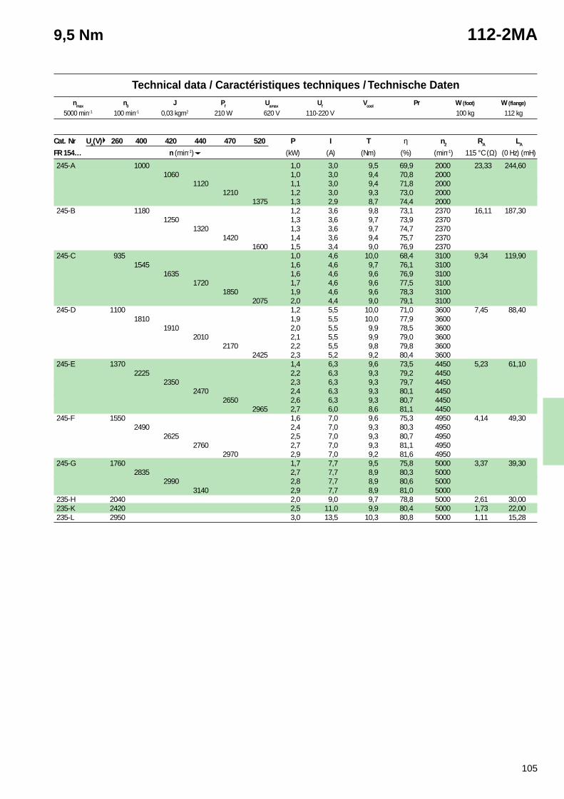
105
Technical data / Caractéristiques techniques / Technische Datennmax n0 J Pf Uamax Uf Vcool Pr W (foot) W (flange)
9,5 Nm 112-2MA
Cat. Nr Ua(V) 260 400 420 440 470 520 P I T η n2 RA LA
FR 154… n (min-1) (kW) (A) (Nm) (%) (min-1) 115 °C (Ω) (0 Hz) (mH)
245-A 1000 1,0 3,0 9,5 69,9 2000 23,33 244,601060 1,0 3,0 9,4 70,8 2000
1120 1,1 3,0 9,4 71,8 20001210 1,2 3,0 9,3 73,0 2000
1375 1,3 2,9 8,7 74,4 2000245-B 1180 1,2 3,6 9,8 73,1 2370 16,11 187,30
1250 1,3 3,6 9,7 73,9 23701320 1,3 3,6 9,7 74,7 2370
1420 1,4 3,6 9,4 75,7 23701600 1,5 3,4 9,0 76,9 2370
245-C 935 1,0 4,6 10,0 68,4 3100 9,34 119,901545 1,6 4,6 9,7 76,1 3100
1635 1,6 4,6 9,6 76,9 31001720 1,7 4,6 9,6 77,5 3100
1850 1,9 4,6 9,6 78,3 31002075 2,0 4,4 9,0 79,1 3100
245-D 1100 1,2 5,5 10,0 71,0 3600 7,45 88,401810 1,9 5,5 10,0 77,9 3600
1910 2,0 5,5 9,9 78,5 36002010 2,1 5,5 9,9 79,0 3600
2170 2,2 5,5 9,8 79,8 36002425 2,3 5,2 9,2 80,4 3600
245-E 1370 1,4 6,3 9,6 73,5 4450 5,23 61,102225 2,2 6,3 9,3 79,2 4450
2350 2,3 6,3 9,3 79,7 44502470 2,4 6,3 9,3 80,1 4450
2650 2,6 6,3 9,3 80,7 44502965 2,7 6,0 8,6 81,1 4450
245-F 1550 1,6 7,0 9,6 75,3 4950 4,14 49,302490 2,4 7,0 9,3 80,3 4950
2625 2,5 7,0 9,3 80,7 49502760 2,7 7,0 9,3 81,1 4950
2970 2,9 7,0 9,2 81,6 4950245-G 1760 1,7 7,7 9,5 75,8 5000 3,37 39,30
2835 2,7 7,7 8,9 80,3 50002990 2,8 7,7 8,9 80,6 5000
3140 2,9 7,7 8,9 81,0 5000235-H 2040 2,0 9,0 9,7 78,8 5000 2,61 30,00235-K 2420 2,5 11,0 9,9 80,4 5000 1,73 22,00235-L 2950 3,0 13,5 10,3 80,8 5000 1,11 15,28
5000 min-1 100 min-1 0,03 kgm2 210 W 620 V 110-220 V 100 kg 112 kg
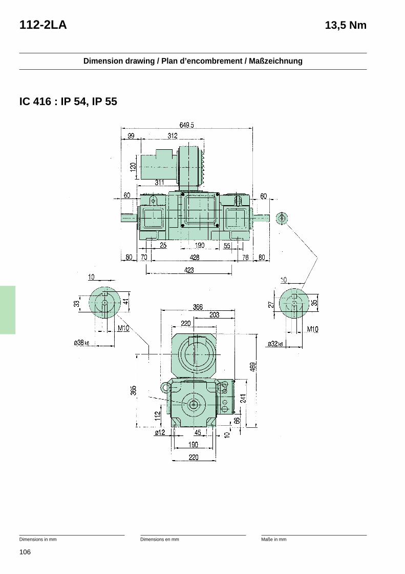
106
Dimension drawing / Plan d’encombrement / Maßzeichnung
Dimensions in mm Dimensions en mm Maße in mm
112-2LA 13,5 Nm
IC 416 : IP 54, IP 55
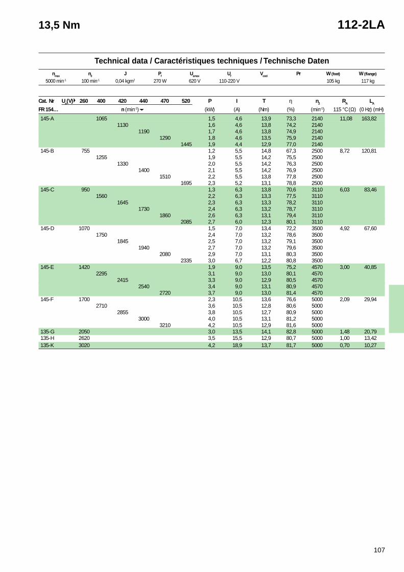
107
Technical data / Caractéristiques techniques / Technische Datennmax n0 J Pf Uamax Uf Vcool Pr W (foot) W (flange)
13,5 Nm 112-2LA
Cat. Nr Ua(V) 260 400 420 440 470 520 P I T η n2 RA LA
FR 154… n (min-1) (kW) (A) (Nm) (%) (min-1) 115 °C (Ω) (0 Hz) (mH)
145-A 1065 1,5 4,6 13,9 73,3 2140 11,08 163,821130 1,6 4,6 13,8 74,2 2140
1190 1,7 4,6 13,8 74,9 21401290 1,8 4,6 13,5 75,9 2140
1445 1,9 4,4 12,9 77,0 2140145-B 755 1,2 5,5 14,8 67,3 2500 8,72 120,81
1255 1,9 5,5 14,2 75,5 25001330 2,0 5,5 14,2 76,3 2500
1400 2,1 5,5 14,2 76,9 25001510 2,2 5,5 13,8 77,8 2500
1695 2,3 5,2 13,1 78,8 2500145-C 950 1,3 6,3 13,8 70,6 3110 6,03 83,46
1560 2,2 6,3 13,3 77,5 31101645 2,3 6,3 13,3 78,2 3110
1730 2,4 6,3 13,2 78,7 31101860 2,6 6,3 13,1 79,4 3110
2085 2,7 6,0 12,3 80,1 3110145-D 1070 1,5 7,0 13,4 72,2 3500 4,92 67,60
1750 2,4 7,0 13,2 78,6 35001845 2,5 7,0 13,2 79,1 3500
1940 2,7 7,0 13,2 79,6 35002080 2,9 7,0 13,1 80,3 3500
2335 3,0 6,7 12,2 80,8 3500145-E 1420 1,9 9,0 13,5 75,2 4570 3,00 40,85
2295 3,1 9,0 13,0 80,1 45702415 3,3 9,0 12,9 80,5 4570
2540 3,4 9,0 13,1 80,9 45702720 3,7 9,0 13,0 81,4 4570
145-F 1700 2,3 10,5 13,6 76,6 5000 2,09 29,942710 3,6 10,5 12,8 80,6 5000
2855 3,8 10,5 12,7 80,9 50003000 4,0 10,5 13,1 81,2 5000
3210 4,2 10,5 12,9 81,6 5000135-G 2050 3,0 13,5 14,1 82,8 5000 1,48 20,79135-H 2620 3,5 15,5 12,9 80,7 5000 1,00 13,42135-K 3020 4,2 18,9 13,7 81,7 5000 0,70 10,27
5000 min-1 100 min-1 0,04 kgm2 270 W 620 V 110-220 V 105 kg 117 kg

108
Dimension drawing / Plan d’encombrement / Maßzeichnung
Dimensions in mm Dimensions en mm Maße in mm
132-2M 18,5 Nm
IC 416 : IP 54, IP 55
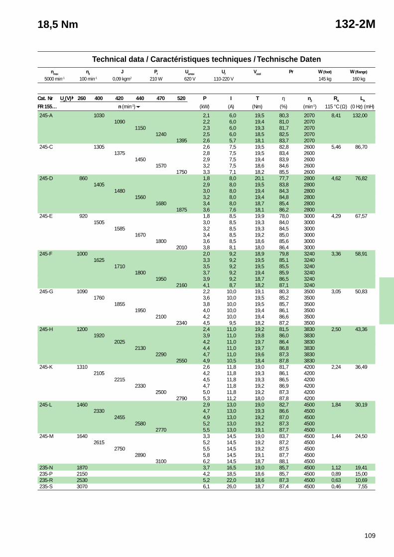
109
Technical data / Caractéristiques techniques / Technische Datennmax n0 J Pf Uamax Uf Vcool Pr W (foot) W (flange)
18,5 Nm 132-2M
Cat. Nr Ua(V) 260 400 420 440 470 520 P I T η n2 RA LA
FR 155… n (min-1) (kW) (A) (Nm) (%) (min-1) 115 °C (Ω) (0 Hz) (mH)
245-A 1030 2,1 6,0 19,5 80,3 2070 8,41 132,001090 2,2 6,0 19,4 81,0 2070
1150 2,3 6,0 19,3 81,7 20701240 2,5 6,0 18,5 82,5 2070
1395 2,6 5,7 18,1 83,7 2070245-C 1305 2,6 7,5 19,5 82,8 2600 5,46 86,70
1375 2,8 7,5 19,5 83,4 26001450 2,9 7,5 19,4 83,9 2600
1570 3,2 7,5 18,6 84,6 26001750 3,3 7,1 18,2 85,5 2600
245-D 860 1,8 8,0 20,1 77,7 2800 4,62 76,821405 2,9 8,0 19,5 83,8 2800
1480 3,0 8,0 19,4 84,3 28001560 3,2 8,0 19,4 84,8 2800
1680 3,4 8,0 18,7 85,4 28001875 3,6 7,6 18,1 86,2 2800
245-E 920 1,8 8,5 19,9 78,0 3000 4,29 67,571505 3,0 8,5 19,3 84,0 3000
1585 3,2 8,5 19,3 84,5 30001670 3,4 8,5 19,2 85,0 3000
1800 3,6 8,5 18,6 85,6 30002010 3,8 8,1 18,0 86,4 3000
245-F 1000 2,0 9,2 18,9 79,8 3240 3,36 58,911625 3,3 9,2 19,5 85,1 3240
1710 3,5 9,2 19,5 85,5 32401800 3,7 9,2 19,4 85,9 3240
1950 3,9 9,2 18,7 86,5 32402160 4,1 8,7 18,2 87,1 3240
245-G 1090 2,2 10,0 19,1 80,3 3500 3,05 50,831760 3,6 10,0 19,5 85,2 3500
1855 3,8 10,0 19,5 85,7 35001950 4,0 10,0 19,4 86,1 3500
2100 4,2 10,0 19,4 86,6 35002340 4,5 9,5 18,2 87,2 3500
245-H 1200 2,4 11,0 19,2 81,5 3830 2,50 43,361920 3,9 11,0 19,8 86,0 3830
2025 4,2 11,0 19,7 86,4 38302130 4,4 11,0 19,7 86,8 3830
2290 4,7 11,0 19,6 87,3 38302550 4,9 10,5 18,4 87,8 3830
245-K 1310 2,6 11,8 19,0 81,7 4200 2,24 36,492105 4,2 11,8 19,3 86,1 4200
2215 4,5 11,8 19,3 86,5 42002330 4,7 11,8 19,2 86,9 4200
2500 5,0 11,8 19,2 87,3 42002790 5,3 11,2 18,0 87,8 4200
245-L 1460 2,9 13,0 19,0 82,7 4500 1,84 30,192330 4,7 13,0 19,3 86,6 4500
2455 4,9 13,0 19,2 87,0 45002580 5,2 13,0 19,2 87,3 4500
2770 5,5 13,0 19,1 87,7 4500245-M 1640 3,3 14,5 19,0 83,7 4500 1,44 24,50
2615 5,2 14,5 19,2 87,2 45002750 5,5 14,5 19,2 87,5 4500
2890 5,8 14,5 19,1 87,7 45003100 6,2 14,5 18,7 88,1 4500
235-N 1870 3,7 16,5 19,0 85,7 4500 1,12 19,41235-P 2150 4,2 18,5 18,6 85,7 4500 0,89 15,00235-R 2530 5,2 22,0 18,6 87,3 4500 0,63 10,69235-S 3070 6,1 26,0 18,7 87,4 4500 0,46 7,55
5000 min-1 100 min-1 0,09 kgm2 210 W 620 V 110-220 V 145 kg 160 kg
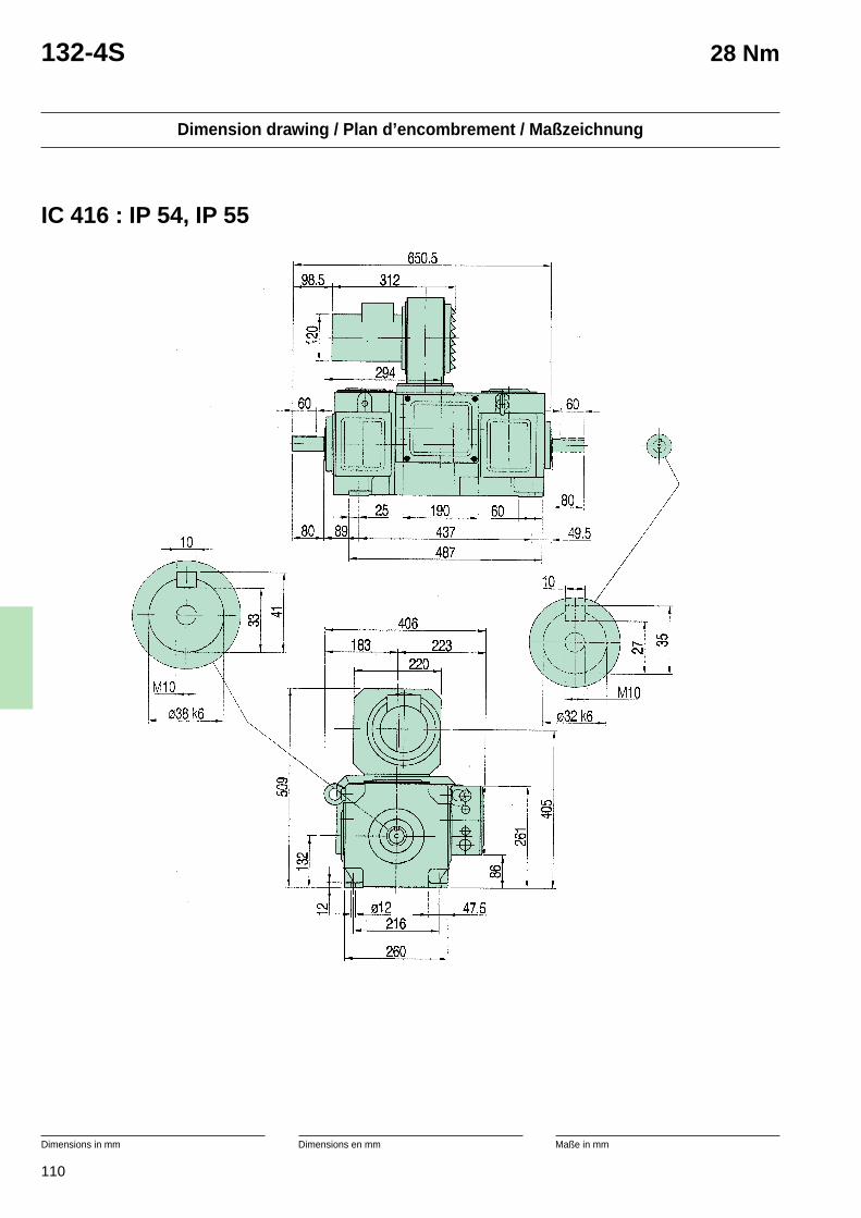
110
Dimension drawing / Plan d’encombrement / Maßzeichnung
Dimensions in mm Dimensions en mm Maße in mm
132-4S 28 Nm
IC 416 : IP 54, IP 55
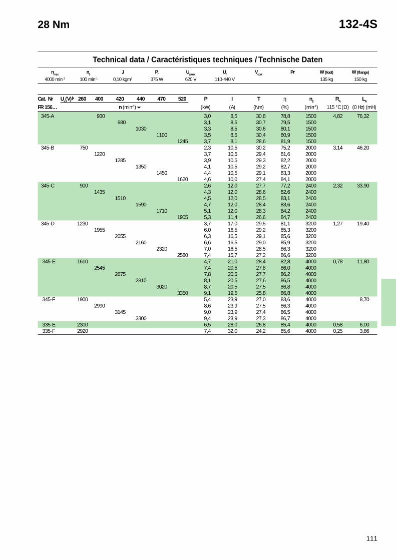
111
Technical data / Caractéristiques techniques / Technische Datennmax n0 J Pf Uamax Uf Vcool Pr W (foot) W (flange)
28 Nm 132-4S
Cat. Nr Ua(V) 260 400 420 440 470 520 P I T η n2 RA LA
FR 156… n (min-1) (kW) (A) (Nm) (%) (min-1) 115 °C (Ω) (0 Hz) (mH)
345-A 930 3,0 8,5 30,8 78,8 1500 4,82 76,32980 3,1 8,5 30,7 79,5 1500
1030 3,3 8,5 30,6 80,1 15001100 3,5 8,5 30,4 80,9 1500
1245 3,7 8,1 28,6 81,9 1500 345-B 750 2,3 10,5 30,2 75,2 2000 3,14 46,20
1220 3,7 10,5 29,4 81,6 20001285 3,9 10,5 29,3 82,2 2000
1350 4,1 10,5 29,2 82,7 20001450 4,4 10,5 29,1 83,3 2000
1620 4,6 10,0 27,4 84,1 2000 345-C 900 2,6 12,0 27,7 77,2 2400 2,32 33,90
1435 4,3 12,0 28,6 82,6 24001510 4,5 12,0 28,5 83,1 2400
1590 4,7 12,0 28,4 83,6 24001710 5,1 12,0 28,3 84,2 2400
1905 5,3 11,4 26,6 84,7 2400 345-D 1230 3,7 17,0 29,5 81,1 3200 1,27 19,40
1955 6,0 16,5 29,2 85,3 32002055 6,3 16,5 29,1 85,6 3200
2160 6,6 16,5 29,0 85,9 32002320 7,0 16,5 28,5 86,3 3200
2580 7,4 15,7 27,2 86,6 3200 345-E 1610 4,7 21,0 28,4 82,8 4000 0,78 11,80
2545 7,4 20,5 27,8 86,0 40002675 7,8 20,5 27,7 86,2 4000
2810 8,1 20,5 27,6 86,5 40003020 8,7 20,5 27,5 86,8 4000
3350 9,1 19,5 25,8 86,8 4000 345-F 1900 5,4 23,9 27,0 83,6 4000 8,70
2990 8,6 23,9 27,5 86,3 40003145 9,0 23,9 27,4 86,5 4000
3300 9,4 23,9 27,3 86,7 4000 335-E 2300 6,5 28,0 26,8 85,4 4000 0,58 6,00 335-F 2920 7,4 32,0 24,2 85,6 4000 0,25 3,86
4000 min-1 100 min-1 0,10 kgm2 375 W 620 V 110-440 V 135 kg 150 kg
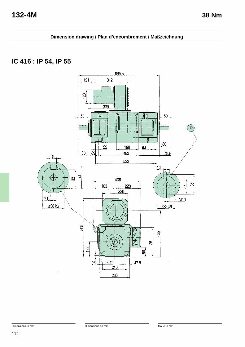
112
Dimension drawing / Plan d’encombrement / Maßzeichnung
Dimensions in mm Dimensions en mm Maße in mm
132-4M 38 Nm
IC 416 : IP 54, IP 55

113
Technical data / Caractéristiques techniques / Technische Datennmax n0 J Pf Uamax Uf Vcool Pr W (foot) W (flange)
38 Nm 132-4M
Cat. Nr Ua(V) 260 400 420 440 470 520 P I T η n2 RA LA
FR 156… n (min-1) (kW) (A) (Nm) (%) (min-1) 115 °C (Ω) (0 Hz) (mH)
245-A 880 3,7 10,5 40,5 80,2 1500 3,90 57,00930 3,9 10,5 40,4 80,9 1500
980 4,1 10,5 40,3 81,5 15001060 4,4 10,5 40,1 82,3 1500
1185 4,7 10,0 37,7 83,2 1500245-B 1055 4,3 12,0 38,8 81,5 1750 2,75 42,00
1120 4,5 12,0 38,7 82,1 17501170 4,7 12,0 38,6 82,6 1750
1260 5,1 12,0 38,5 83,3 17501405 5,3 11,4 36,2 84,0 1750
245-C 900 3,7 16,5 39,0 79,8 2400 1,45 23,601445 6,0 16,5 39,6 84,7 2400
1525 6,3 16,5 39,5 85,2 24001600 6,6 16,5 39,4 85,5 2400
1710 7,0 16,5 39,2 86,0 24001915 7,4 15,7 36,9 86,5 2400
245-D 1180 4,8 21,0 38,5 82,4 3100 0,90 14,201880 7,7 21,0 39,0 86,3 3100
1975 8,0 21,0 38,9 86,6 31002075 8,4 21,0 38,8 86,9 3100
2220 9,0 21,0 38,6 87,3 31002475 9,4 20,0 36,4 87,6 3100
245-E 1400 5,6 24,5 38,0 83,6 3600 0,65 10,502210 8,9 24,5 38,6 87,0 3600
2325 9,4 24,5 38,6 87,3 36002440 9,8 24,5 38,5 87,5 3600
2610 10,5 24,3 38,3 87,8 36002905 11,0 23,3 36,1 88,0 3600
245-F 1700 6,5 28,0 36,5 84,9 4000 0,49 7,302665 10,3 28,2 36,9 87,5 4000
2800 10,8 28,2 36,8 87,7 40002940 11,3 28,2 36,7 87,9 4000
3150 12,1 28,2 36,6 88,2 4000235-E 2150 8,3 35,0 36,5 86,7 4000 0,42 4,60235-F 2900 9,1 39,0 29,9 86,1 4000 0,25 2,59
4000 min-1 100 min-1 0,12 kgm2 450 W 620 V 110-440 V 155 kg 170 kg
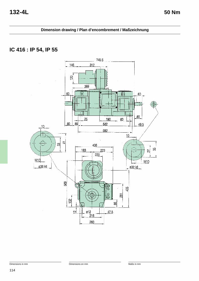
114
Dimension drawing / Plan d’encombrement / Maßzeichnung
Dimensions in mm Dimensions en mm Maße in mm
132-4L 50 Nm
IC 416 : IP 54, IP 55
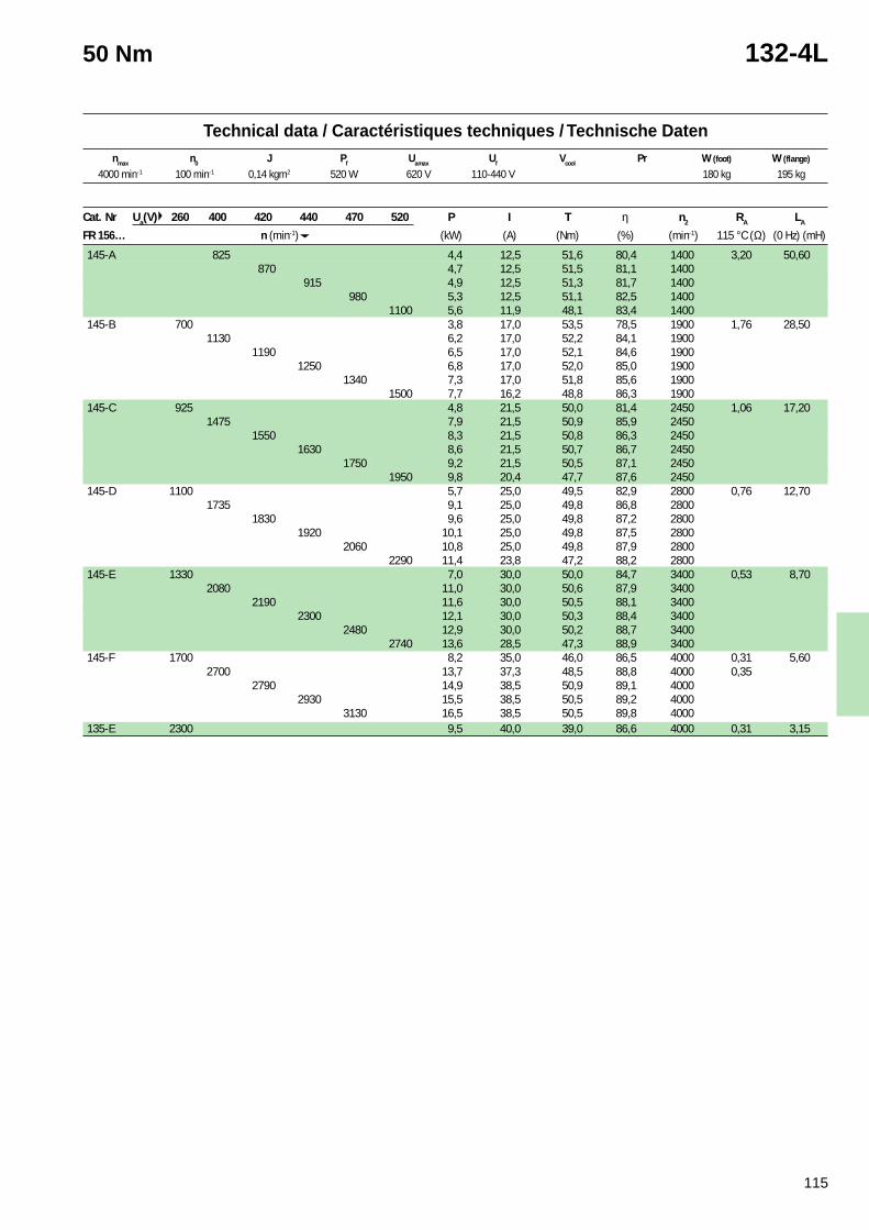
115
Technical data / Caractéristiques techniques / Technische Datennmax n0 J Pf Uamax Uf Vcool Pr W (foot) W (flange)
50 Nm 132-4L
Cat. Nr Ua(V) 260 400 420 440 470 520 P I T η n2 RA LA
FR 156… n (min-1) (kW) (A) (Nm) (%) (min-1) 115 °C (Ω) (0 Hz) (mH)
145-A 825 4,4 12,5 51,6 80,4 1400 3,20 50,60870 4,7 12,5 51,5 81,1 1400
915 4,9 12,5 51,3 81,7 1400980 5,3 12,5 51,1 82,5 1400
1100 5,6 11,9 48,1 83,4 1400145-B 700 3,8 17,0 53,5 78,5 1900 1,76 28,50
1130 6,2 17,0 52,2 84,1 19001190 6,5 17,0 52,1 84,6 1900
1250 6,8 17,0 52,0 85,0 19001340 7,3 17,0 51,8 85,6 1900
1500 7,7 16,2 48,8 86,3 1900145-C 925 4,8 21,5 50,0 81,4 2450 1,06 17,20
1475 7,9 21,5 50,9 85,9 24501550 8,3 21,5 50,8 86,3 2450
1630 8,6 21,5 50,7 86,7 24501750 9,2 21,5 50,5 87,1 2450
1950 9,8 20,4 47,7 87,6 2450145-D 1100 5,7 25,0 49,5 82,9 2800 0,76 12,70
1735 9,1 25,0 49,8 86,8 28001830 9,6 25,0 49,8 87,2 2800
1920 10,1 25,0 49,8 87,5 28002060 10,8 25,0 49,8 87,9 2800
2290 11,4 23,8 47,2 88,2 2800145-E 1330 7,0 30,0 50,0 84,7 3400 0,53 8,70
2080 11,0 30,0 50,6 87,9 34002190 11,6 30,0 50,5 88,1 3400
2300 12,1 30,0 50,3 88,4 34002480 12,9 30,0 50,2 88,7 3400
2740 13,6 28,5 47,3 88,9 3400145-F 1700 8,2 35,0 46,0 86,5 4000 0,31 5,60
2700 13,7 37,3 48,5 88,8 4000 0,352790 14,9 38,5 50,9 89,1 4000
2930 15,5 38,5 50,5 89,2 40003130 16,5 38,5 50,5 89,8 4000
135-E 2300 9,5 40,0 39,0 86,6 4000 0,31 3,15
4000 min-1 100 min-1 0,14 kgm2 520 W 620 V 110-440 V 180 kg 195 kg
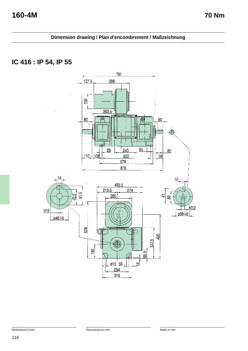
116
Dimension drawing / Plan d’encombrement / Maßzeichnung
Dimensions in mm Dimensions en mm Maße in mm
160-4M 70 Nm
IC 416 : IP 54, IP 55
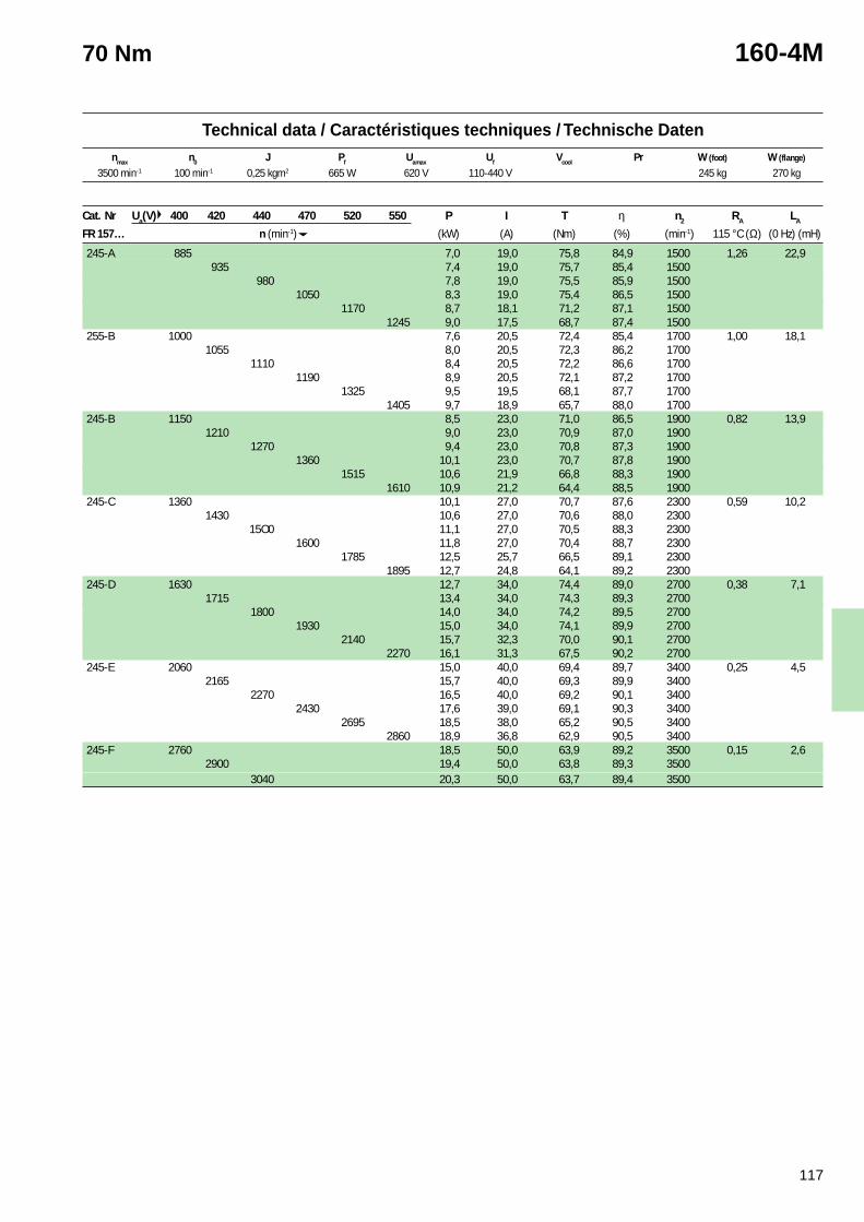
117
Technical data / Caractéristiques techniques / Technische Datennmax n0 J Pf Uamax Uf Vcool Pr W (foot) W (flange)
70 Nm 160-4M
Cat. Nr Ua(V) 400 420 440 470 520 550 P I T η n2 RA LA
FR 157… n (min-1) (kW) (A) (Nm) (%) (min-1) 115 °C (Ω) (0 Hz) (mH)
245-A 885 7,0 19,0 75,8 84,9 1500 1,26 22,9935 7,4 19,0 75,7 85,4 1500
980 7,8 19,0 75,5 85,9 15001050 8,3 19,0 75,4 86,5 1500
1170 8,7 18,1 71,2 87,1 15001245 9,0 17,5 68,7 87,4 1500
255-B 1000 7,6 20,5 72,4 85,4 1700 1,00 18,11055 8,0 20,5 72,3 86,2 1700
1110 8,4 20,5 72,2 86,6 17001190 8,9 20,5 72,1 87,2 1700
1325 9,5 19,5 68,1 87,7 17001405 9,7 18,9 65,7 88,0 1700
245-B 1150 8,5 23,0 71,0 86,5 1900 0,82 13,91210 9,0 23,0 70,9 87,0 1900
1270 9,4 23,0 70,8 87,3 19001360 10,1 23,0 70,7 87,8 1900
1515 10,6 21,9 66,8 88,3 19001610 10,9 21,2 64,4 88,5 1900
245-C 1360 10,1 27,0 70,7 87,6 2300 0,59 10,21430 10,6 27,0 70,6 88,0 2300
15O0 11,1 27,0 70,5 88,3 23001600 11,8 27,0 70,4 88,7 2300
1785 12,5 25,7 66,5 89,1 23001895 12,7 24,8 64,1 89,2 2300
245-D 1630 12,7 34,0 74,4 89,0 2700 0,38 7,11715 13,4 34,0 74,3 89,3 2700
1800 14,0 34,0 74,2 89,5 27001930 15,0 34,0 74,1 89,9 2700
2140 15,7 32,3 70,0 90,1 27002270 16,1 31,3 67,5 90,2 2700
245-E 2060 15,0 40,0 69,4 89,7 3400 0,25 4,52165 15,7 40,0 69,3 89,9 3400
2270 16,5 40,0 69,2 90,1 34002430 17,6 39,0 69,1 90,3 3400
2695 18,5 38,0 65,2 90,5 34002860 18,9 36,8 62,9 90,5 3400
245-F 2760 18,5 50,0 63,9 89,2 3500 0,15 2,62900 19,4 50,0 63,8 89,3 3500
3040 20,3 50,0 63,7 89,4 3500
3500 min-1 100 min-1 0,25 kgm2 665 W 620 V 110-440 V 245 kg 270 kg
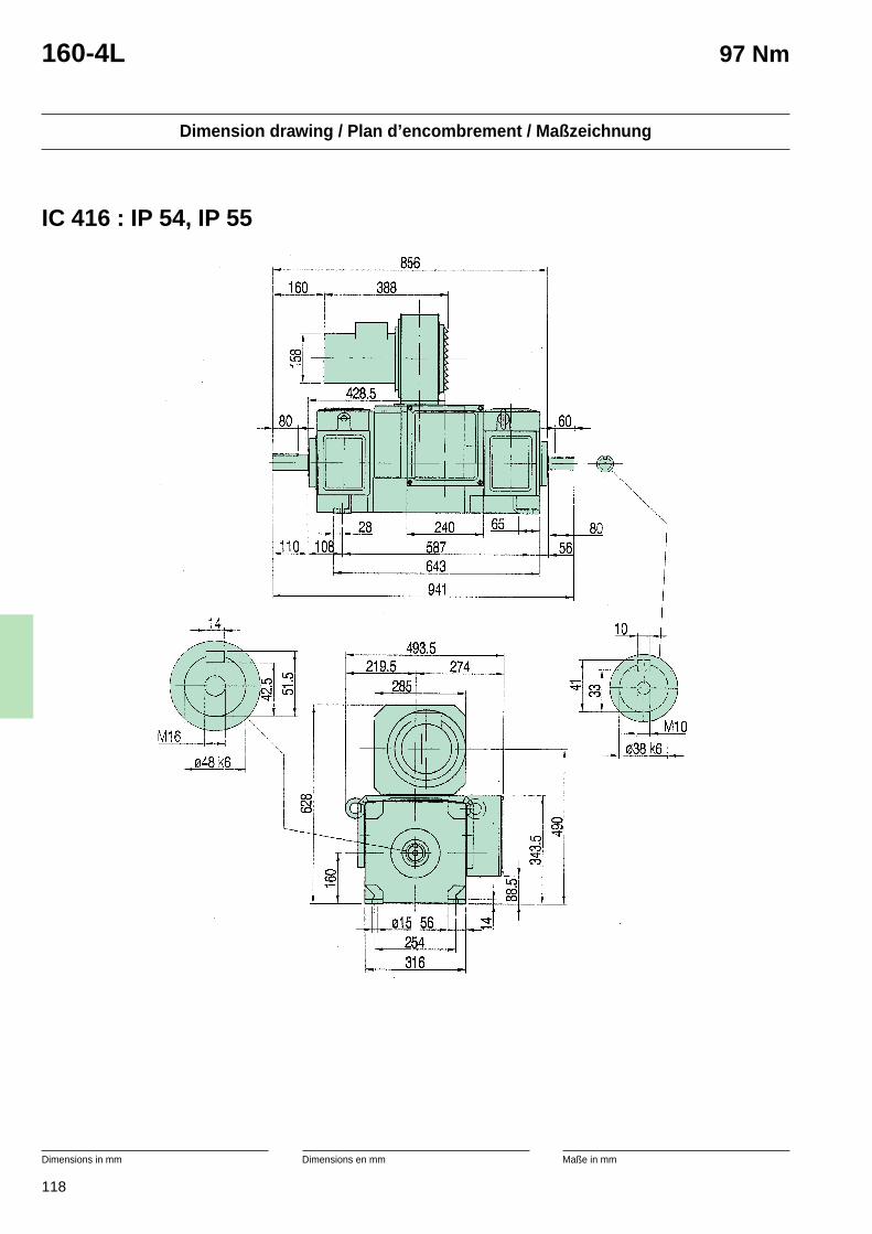
118
Dimension drawing / Plan d’encombrement / Maßzeichnung
Dimensions in mm Dimensions en mm Maße in mm
160-4L 97 Nm
IC 416 : IP 54, IP 55
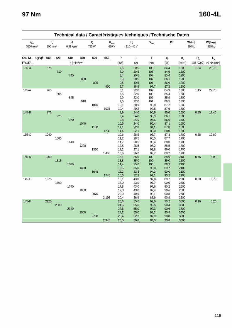
119
Technical data / Caractéristiques techniques / Technische Datennmax n0 J Pf Uamax Uf Vcool Pr W (foot) W (flange)
97 Nm 160-4L
Cat. Nr Ua(V) 400 420 440 470 520 550 P I T η n2 RA LA
FR 157… n (min-1) (kW) (A) (Nm) (%) (min-1) 115 °C (Ω) (0 Hz) (mH)
155-A 675 7,6 20,5 108 84,4 1200 1,34 28,73710 8,0 20,5 108 84,9 1200
745 8,4 20,5 107 85,4 1200800 8,9 20,5 107 86,1 1200
895 9,5 19,5 101 86,9 1200950 9,7 18,9 97,7 87,2 1200
145-A 765 8,1 22,0 102 84,9 1300 1,15 22,70805 8,6 22,0 102 85,4 1300
845 9,0 22,0 102 85,9 1300910 9,6 22,0 101 86,5 1300
1010 10,1 20,9 95,8 87,2 13001075 10,4 20,2 92,5 87,6 1300
145-B 875 8,9 24,0 96,9 85,6 1500 0,95 17,40925 9,4 24,0 96,8 86,1 1500
970 9,8 24,0 96,6 86,6 15001040 10,5 24,0 96,4 87,1 1500
1160 11,1 22,8 91,1 87,8 15001230 11,4 22,1 88,0 88,0 1500
155-C 1040 10,6 28,5 98,7 87,3 1700 0,68 12,801085 11,2 28,5 98,5 87,7 1700
1140 11,7 28,5 98,4 88,0 17001220 12,5 28,5 98,2 88,5 1700
1360 13,2 27,1 92,8 89,0 17001 440 13,6 26,2 89,7 89,2 1700
145-D 1250 13,1 35,0 100 88,6 2100 0,45 8,901315 13,8 35,0 100 89,0 2100
1380 14,4 35,0 100 89,3 21001480 15,5 35,0 99,8 89,7 2100
1645 16,2 33,3 94,3 90,0 21001745 16,6 32,2 91,1 90,2 2100
145-E 1575 16,1 43,0 97,8 89,7 2600 0,30 5,701660 17,0 43,0 97,7 90,0 2600
1740 17,8 43,0 97,6 90,2 26001860 19,0 43,0 97,4 90,6 2600
2070 20,0 40,9 92,1 90,8 26002 195 20,4 36,9 88,9 90,9 2600
145-F 2120 20,6 55,0 92,6 90,2 3500 0,16 3,202330 21,6 55,0 92,5 90,4 3500
2340 22,6 55,0 92,3 90,6 35002500 24,2 55,0 92,2 90,8 3500
2780 25,4 52,3 87,0 90,8 35002 945 26,0 50,6 84,0 90,8 3500
3500 min-1 100 min-1 0,31 kgm2 780 W 620 V 110-440 V 290 kg 315 kg
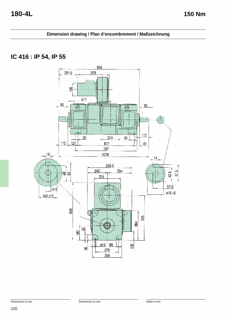
120
Dimension drawing / Plan d’encombrement / Maßzeichnung
Dimensions in mm Dimensions en mm Maße in mm
180-4L 150 Nm
IC 416 : IP 54, IP 55
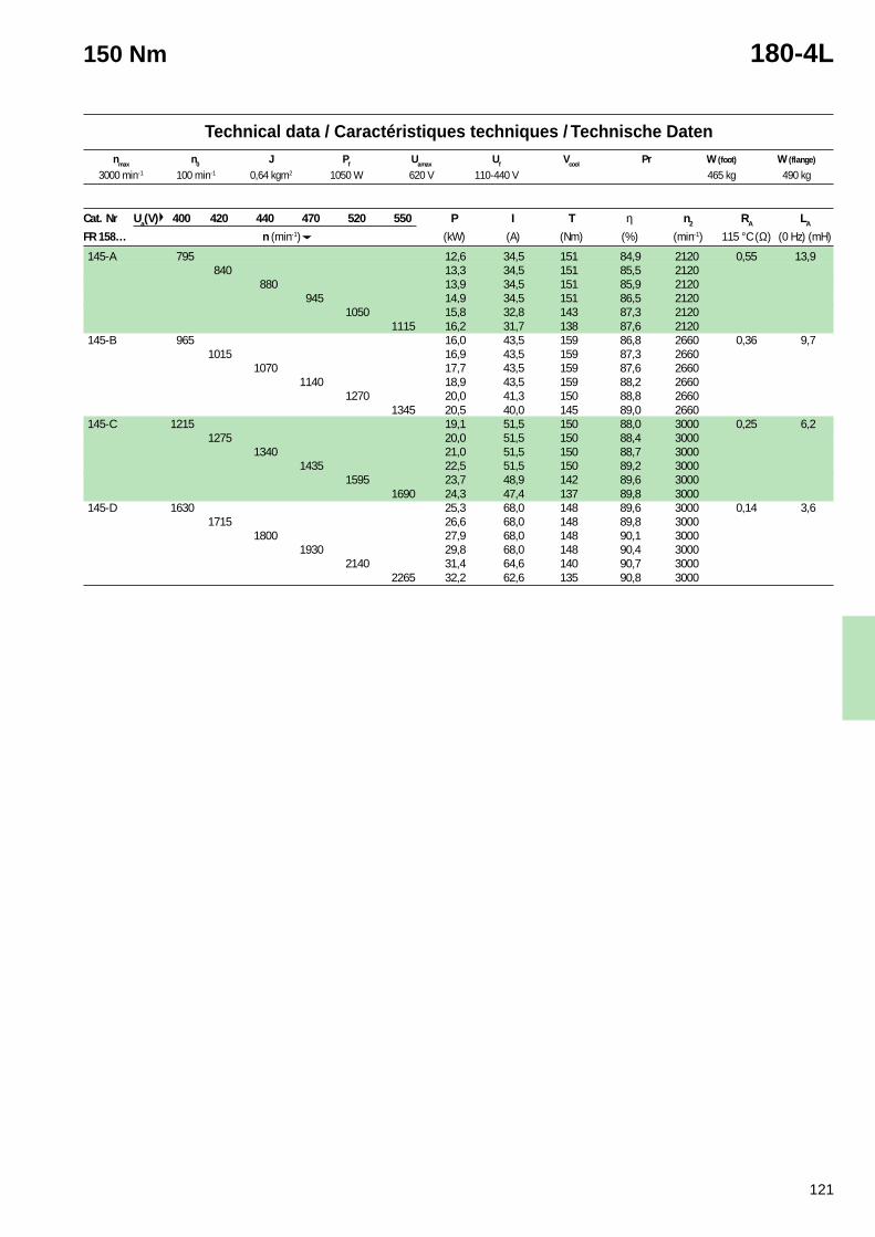
121
Technical data / Caractéristiques techniques / Technische Datennmax n0 J Pf Uamax Uf Vcool Pr W (foot) W (flange)
150 Nm 180-4L
Cat. Nr Ua(V) 400 420 440 470 520 550 P I T η n2 RA LA
FR 158… n (min-1) (kW) (A) (Nm) (%) (min-1) 115 °C (Ω) (0 Hz) (mH)
145-A 795 12,6 34,5 151 84,9 2120 0,55 13,9840 13,3 34,5 151 85,5 2120
880 13,9 34,5 151 85,9 2120945 14,9 34,5 151 86,5 2120
1050 15,8 32,8 143 87,3 21201115 16,2 31,7 138 87,6 2120
145-B 965 16,0 43,5 159 86,8 2660 0,36 9,71015 16,9 43,5 159 87,3 2660
1070 17,7 43,5 159 87,6 26601140 18,9 43,5 159 88,2 2660
1270 20,0 41,3 150 88,8 26601345 20,5 40,0 145 89,0 2660
145-C 1215 19,1 51,5 150 88,0 3000 0,25 6,21275 20,0 51,5 150 88,4 3000
1340 21,0 51,5 150 88,7 30001435 22,5 51,5 150 89,2 3000
1595 23,7 48,9 142 89,6 30001690 24,3 47,4 137 89,8 3000
145-D 1630 25,3 68,0 148 89,6 3000 0,14 3,61715 26,6 68,0 148 89,8 3000
1800 27,9 68,0 148 90,1 30001930 29,8 68,0 148 90,4 3000
2140 31,4 64,6 140 90,7 30002265 32,2 62,6 135 90,8 3000
3000 min-1 100 min-1 0,64 kgm2 1050 W 620 V 110-440 V 465 kg 490 kg
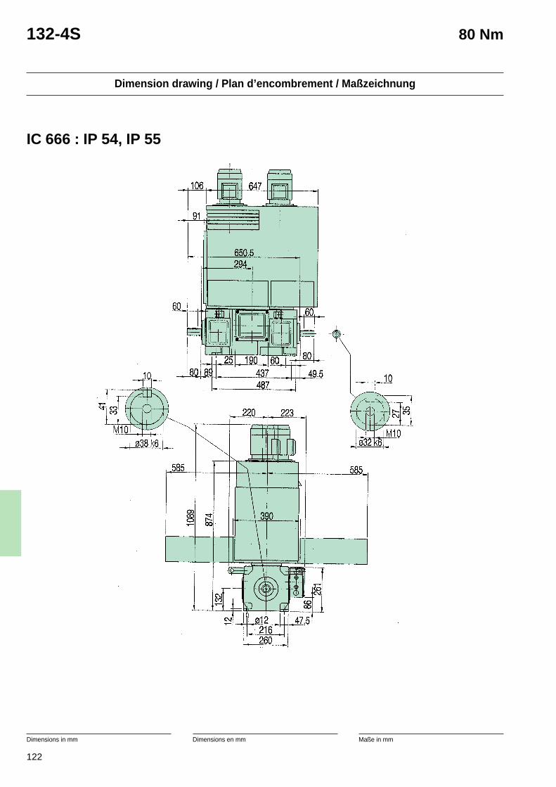
122
Dimension drawing / Plan d’encombrement / Maßzeichnung
Dimensions in mm Dimensions en mm Maße in mm
132-4S 80 Nm
IC 666 : IP 54, IP 55
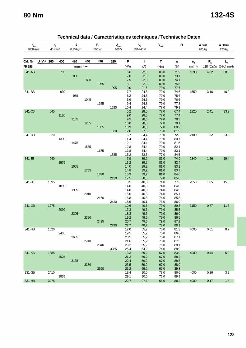
123
Technical data / Caractéristiques techniques / Technische Datennmax n0 J Pf Uamax Uf Vcool Pr W (foot) W (flange)
80 Nm 132-4S
4000 min-1 40 min-1 0,10 kgm2 600 W 620 V 110-440 V 205 kg 220 kg
Cat. Nr Ua(V) 260 400 420 440 470 520 P I T η n2 RA LA
FR 156… n (min-1) (kW) (A) (Nm) (%) (min-1) 115 °C (Ω) (0 Hz) (mH)
341-AB 785 6,6 22,0 80,0 71,9 1390 4,02 60,3835 7,0 22,0 80,0 73,1
890 7,5 22,0 80,0 74,1965 8,1 22,0 80,0 75,5
1095 9,0 21,6 79,0 77,7341-BB 930 7,7 24,8 79,0 74,6 1550 3,16 46,2
985 8,2 24,8 79,0 75,61045 8,6 24,8 79,0 76,6
1355 9,4 24,8 79,0 77,81280 10,4 24,4 78,0 79,8
341-CB 645 5,2 28,0 77,0 67,4 1920 2,41 33,91120 9,0 28,0 77,0 77,4
1185 9,5 28,0 77,0 78,31255 10,0 28,0 77,0 79,1
1355 10,9 28,0 77,0 80,21530 12,0 27,5 75,0 81,9
341-DB 820 6,7 34,4 79,0 72,3 2180 1,62 23,61390 11,4 34,4 79,0 80,7
1475 12,1 34,4 79,0 81,51555 12,8 34,4 79,0 82,1
1675 13,8 34,4 79,0 83,11885 15,2 33,8 77,0 84,5
341-EB 940 7,9 39,2 81,0 74,9 2340 1,26 19,41575 13,2 39,2 81,0 82,4
1665 14,0 39,2 81,0 83,11755 14,8 39,2 81,0 83,7
1890 15,9 39,2 81,0 84,62120 17,5 38,5 79,0 85,8
341-FB 1095 8,5 40,8 74,0 77,3 2850 1,05 15,31805 14,0 40,8 74,0 84,0
1905 14,8 40,8 74,0 84,52010 15,6 40,8 74,0 85,1
2160 16,8 40,8 74,0 85,82420 18,5 40,1 73,0 86,9
341-GB 1275 10,6 49,6 79,0 89,3 3150 0,77 11,82090 17,3 49,6 79,0 85,5
2205 18,3 49,6 79,0 86,02320 19,2 49,6 79,0 86,5
2495 20,7 49,6 79,0 87,22790 22,7 48,7 78,0 88,1
341-HB 1520 12,0 55,2 76,0 81,3 4000 0,61 8,72465 19,5 55,2 75,0 86,6
2605 20,5 55,2 75,0 87,12740 21,6 55,2 75,0 87,5
2940 23,2 55,2 75,0 88,13285 25,4 54,2 74,0 88,9
341-KB 1885 13,3 59,2 67,0 83,9 4000 0,44 5,03025 21,2 59,2 67,0 88,2
3185 22,4 59,2 67,0 88,53350 23,5 59,2 67,0 88,9
3590 25,2 59,2 67,0 89,3331-GB 2410 18,4 80,0 73,0 86,6 4000 0,26 3,2
3835 29,1 80,0 73,0 89,9331-HB 3275 22,7 97,6 66,0 88,2 4000 0,17 1,8
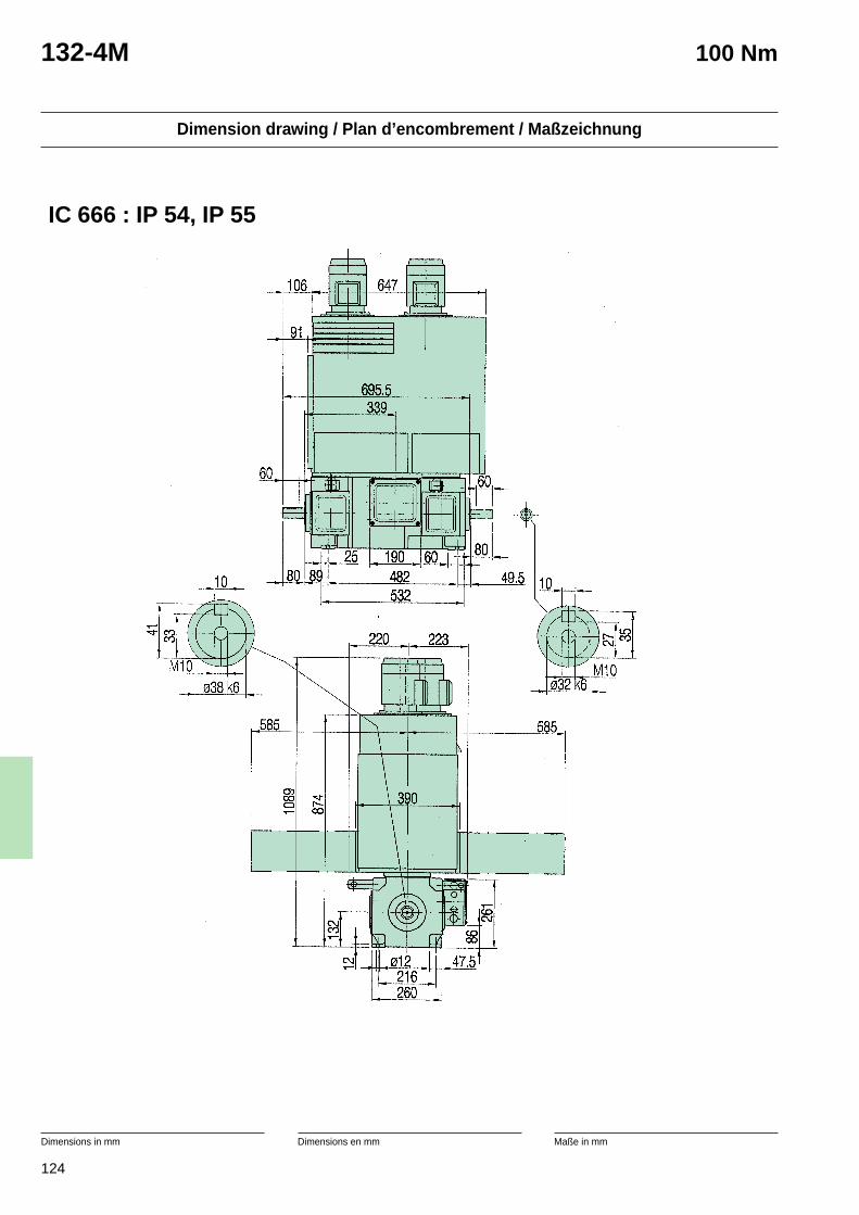
124
Dimension drawing / Plan d’encombrement / Maßzeichnung
Dimensions in mm Dimensions en mm Maße in mm
132-4M 100 Nm
IC 666 : IP 54, IP 55
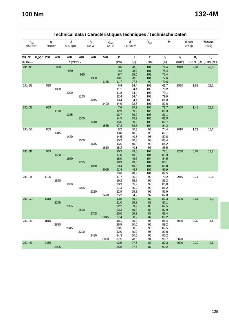
125
Technical data / Caractéristiques techniques / Technische Datennmax n0 J Pf Uamax Uf Vcool Pr W (foot) W (flange)
100 Nm 132-4M
4000 min-1 40 min-1 0,12 kgm2 664 W 620 V 110-440 V 225 kg 240 kg
Cat. Nr Ua(V) 260 400 420 440 470 520 P I T η n2 RA LA
FR 156… n (min-1) (kW) (A) (Nm) (%) (min-1) 115 °C (Ω) (0 Hz) (mH)
241-AB 820 8,6 28,0 101 74,4 1310 2,81 42,0870 9,2 28,0 101 75,4
925 9,7 28,0 101 76,41000 10,5 28,0 101 77,6
1135 11,7 27,5 99 79,6241-BB 595 6,4 34,4 103 68,7 1530 1,88 29,2
1030 11,1 34,4 103 78,21090 11,8 34,4 103 79,1
1150 12,4 34,4 103 79,91245 13,4 34,4 103 81,0
1400 14,9 33,8 101 82,6241-CB 685 7,6 39,2 106 71,7 1655 1,48 23,6
1170 12,9 39,2 106 80,31235 13,7 39,2 106 81,1
1305 14,5 39,2 106 81,81410 15,6 39,2 106 82,7
1585 17,2 38,5 104 84,2241-DB 805 8,2 40,8 98 74,4 2010 1,22 18,7
1345 13,8 40,8 98 82,11420 14,5 40,8 98 82,8
1500 15,3 40,8 98 83,41615 16,5 40,8 98 84,2
1810 18,2 40,1 96 85,5241-EB 945 10,3 49,6 104 77,1 2280 0,89 14,2
1560 17,0 49,6 104 83,91650 18,0 49,6 104 84,5
1735 18,9 49,6 104 85,11870 20,4 49,6 104 85,8
2095 22,4 48,7 102 86,923,6 48,2 101 87,5
241-FB 1125 11,7 55,2 99 79,2 2945 0,71 10,51850 19,2 55,2 99 85,2
1950 20,3 55,2 99 85,82055 21,3 55,2 99 86,2
2210 22,9 55,2 99 86,92470 25,2 54,2 97 87,8
241-GB 1410 13,0 59,2 89 82,3 3590 0,51 7,32275 21,0 59,2 88 87,1
2395 22,2 59,2 88 87,52520 23,3 59,2 88 87,9
2705 25,0 59,2 88 88,43015 27,4 58,2 87 89,2
241-HB 1810 18,1 80,0 96 85,4 4000 0,30 4,62890 28,9 80,0 96 89,2
3045 30,5 80,0 96 89,53200 32,0 80,0 96 89,8
3430 34,3 80,0 96 90,23820 37,5 78,6 94 90,7 3820
231-HB 2465 22,5 97,6 87 87,3 4000 0,19 2,63905 35,6 97,6 87 90,2
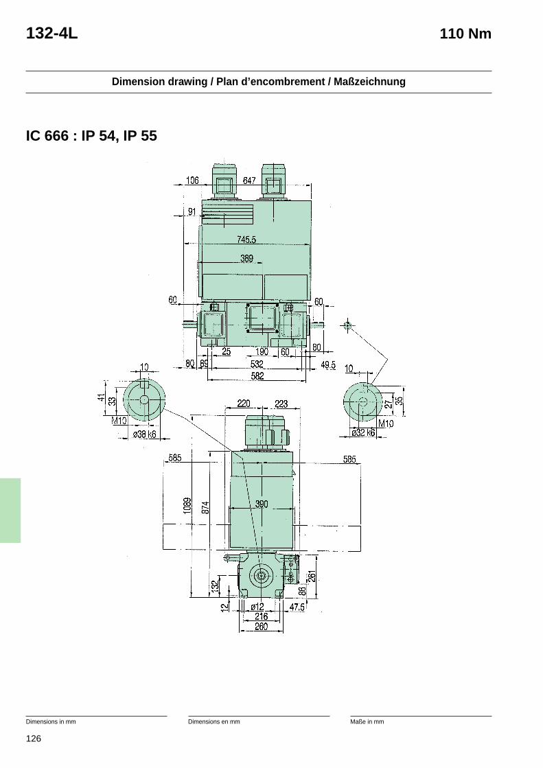
126
Dimension drawing / Plan d’encombrement / Maßzeichnung
Dimensions in mm Dimensions en mm Maße in mm
132-4L 110 Nm
IC 666 : IP 54, IP 55
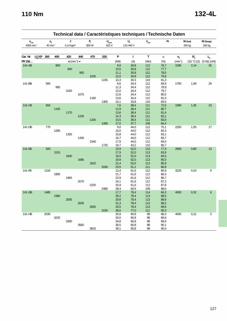
127
Technical data / Caractéristiques techniques / Technische Datennmax n0 J Pf Uamax Uf Vcool Pr W (foot) W (flange)
110 Nm 132-4L
4000 min-1 40 min-1 0,14 kgm2 800 W 620 V 110-440 V 250 kg 265 kg
Cat. Nr Ua(V) 260 400 420 440 470 520 P I T η n2 RA LA
FR 156… n (min-1) (kW) (A) (Nm) (%) (min-1) 115 °C (Ω) (0 Hz) (mH)141-AB 850 9,9 30,8 112 76,7 1595 2,14 35
900 10,5 30,8 112 77,7950 11,1 30,8 112 78,5
1025 12,0 30,8 112 79,61155 13,3 30,3 110 81,3
141-BB 565 6,6 34,4 112 69,9 1750 1,69 29965 11,3 34,4 112 78,9
1020 12,0 34,4 112 79,71075 12,6 34,4 112 80,5
1160 13,6 34,4 112 81,51305 15,1 33,8 110 83,0
141-CB 655 7,6 38,4 111 72,5 1990 1,35 231105 12,9 38,4 111 80,7
1170 13,6 38,4 111 81,41230 14,3 38,4 111 82,1
1330 15,5 38,4 111 83,01490 17,0 37,7 109 84,4
141-DB 770 9,0 44,0 112 75,1 2250 1,05 171285 15,0 44,0 112 82,4
1355 15,8 44,0 112 83,11430 16,7 44,0 112 83,7
1540 17,9 44,0 112 84,51725 19,7 43,2 110 85,7
141-EB 920 10,9 52,0 113 77,3 2665 0,80 131515 17,9 52,0 113 83,9
1600 18,9 52,0 113 84,51685 19,9 52,0 113 85,0
1815 21,4 52,0 113 85,82030 23,5 51,1 111 86,8
141-FB 1150 13,4 61,6 112 80,9 3225 0,53 91865 21,7 61,6 112 86,3
1965 22,9 61,6 112 86,72070 24,1 61,6 112 87,2
2220 25,9 61,6 112 87,82480 28,4 60,5 109 88,6
141-GB 1485 17,7 78,4 114 84,3 4000 0,32 62380 28,2 78,4 113 88,5
2505 29,8 78,4 113 88,92635 31,3 78,4 113 89,2
2825 33,5 78,4 113 89,63150 36,6 77,0 111 90,3
141-HB 2030 20,9 90,8 98 86,3 4000 0,21 33220 33,0 90,8 98 89,6
3390 34,8 90,8 98 89,93560 36,5 90,8 98 90,1
3815 39,1 90,8 98 90,4
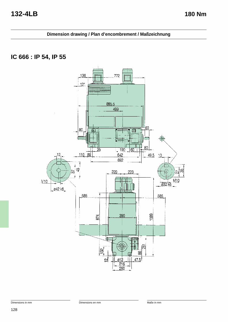
128
Dimension drawing / Plan d’encombrement / Maßzeichnung
Dimensions in mm Dimensions en mm Maße in mm
132-4LB 180 Nm
IC 666 : IP 54, IP 55
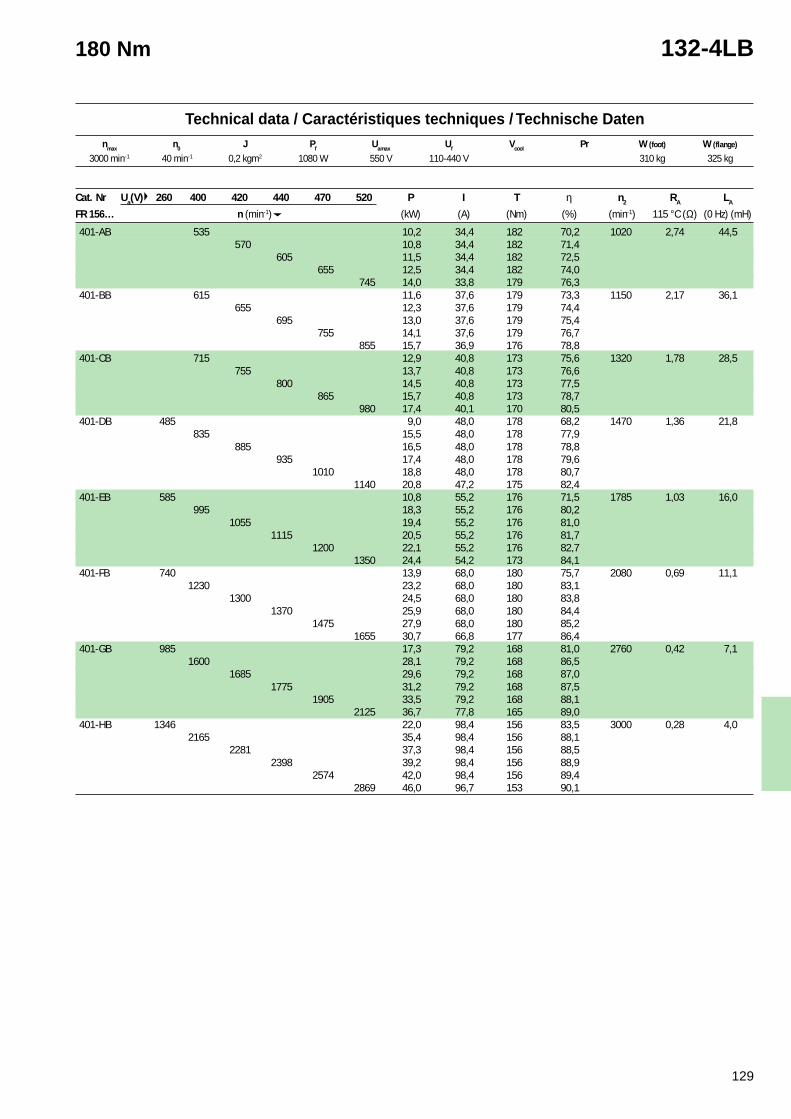
129
Technical data / Caractéristiques techniques / Technische Datennmax n0 J Pf Uamax Uf Vcool Pr W (foot) W (flange)
180 Nm 132-4LB
3000 min-1 40 min-1 0,2 kgm2 1080 W 550 V 110-440 V 310 kg 325 kg
Cat. Nr Ua(V) 260 400 420 440 470 520 P I T η n2 RA LA
FR 156… n (min-1) (kW) (A) (Nm) (%) (min-1) 115 °C (Ω) (0 Hz) (mH)
401-AB 535 10,2 34,4 182 70,2 1020 2,74 44,5570 10,8 34,4 182 71,4
605 11,5 34,4 182 72,5655 12,5 34,4 182 74,0
745 14,0 33,8 179 76,3401-BB 615 11,6 37,6 179 73,3 1150 2,17 36,1
655 12,3 37,6 179 74,4695 13,0 37,6 179 75,4
755 14,1 37,6 179 76,7855 15,7 36,9 176 78,8
401-CB 715 12,9 40,8 173 75,6 1320 1,78 28,5755 13,7 40,8 173 76,6
800 14,5 40,8 173 77,5865 15,7 40,8 173 78,7
980 17,4 40,1 170 80,5401-DB 485 9,0 48,0 178 68,2 1470 1,36 21,8
835 15,5 48,0 178 77,9885 16,5 48,0 178 78,8
935 17,4 48,0 178 79,61010 18,8 48,0 178 80,7
1140 20,8 47,2 175 82,4401-EB 585 10,8 55,2 176 71,5 1785 1,03 16,0
995 18,3 55,2 176 80,21055 19,4 55,2 176 81,0
1115 20,5 55,2 176 81,71200 22,1 55,2 176 82,7
1350 24,4 54,2 173 84,1401-FB 740 13,9 68,0 180 75,7 2080 0,69 11,1
1230 23,2 68,0 180 83,11300 24,5 68,0 180 83,8
1370 25,9 68,0 180 84,41475 27,9 68,0 180 85,2
1655 30,7 66,8 177 86,4401-GB 985 17,3 79,2 168 81,0 2760 0,42 7,1
1600 28,1 79,2 168 86,51685 29,6 79,2 168 87,0
1775 31,2 79,2 168 87,51905 33,5 79,2 168 88,1
2125 36,7 77,8 165 89,0401-HB 1346 22,0 98,4 156 83,5 3000 0,28 4,0
2165 35,4 98,4 156 88,12281 37,3 98,4 156 88,5
2398 39,2 98,4 156 88,92574 42,0 98,4 156 89,4
2869 46,0 96,7 153 90,1
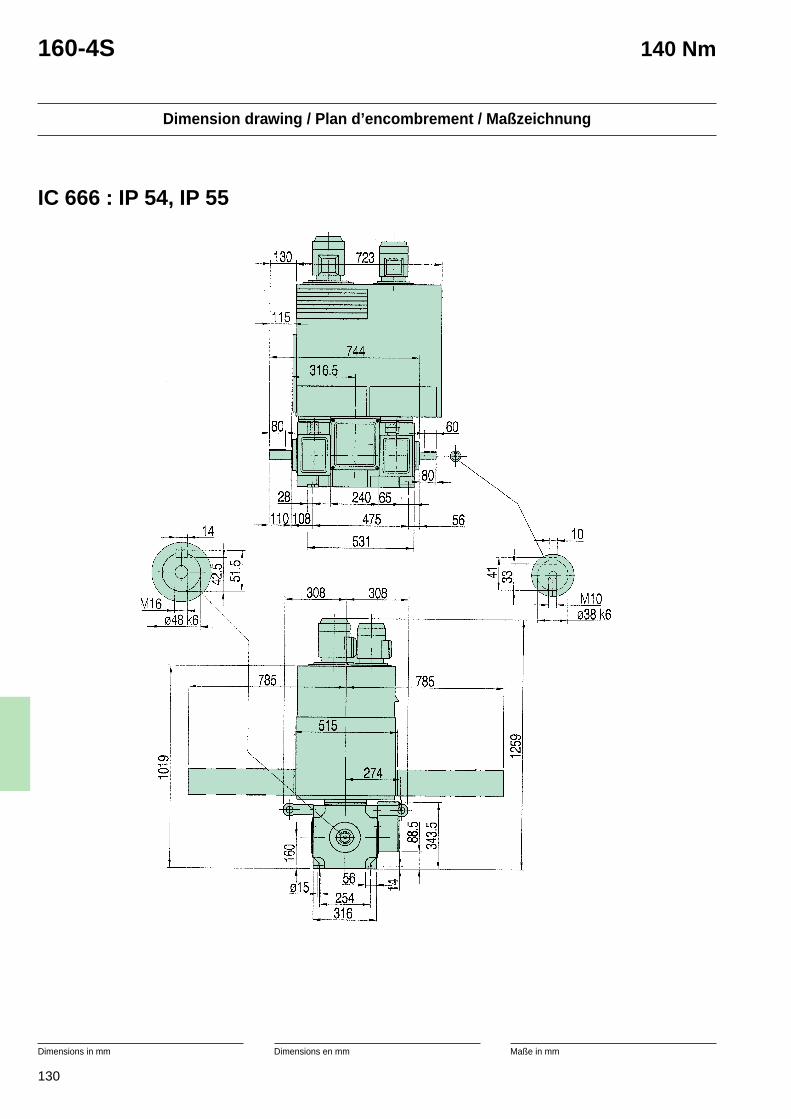
130
Dimension drawing / Plan d’encombrement / Maßzeichnung
Dimensions in mm Dimensions en mm Maße in mm
160-4S 140 Nm
IC 666 : IP 54, IP 55
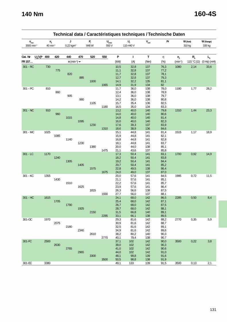
131
Technical data / Caractéristiques techniques / Technische Datennmax n0 J Pf Uamax Uf Vcool Pr W (foot) W (flange)
140 Nm 160-4S
3500 min-1 40 min-1 0,22 kgm2 848 W 550 V 110-440 V 310 kg 335 kg
Cat. Nr Ua(V) 400 420 440 470 520 550 P I T η n2 RA LA
FR 157… n (min-1) (kW) (A) (Nm) (%) (min-1) 115 °C (Ω) (0 Hz) (mH)
301 - RC 730 10,5 32,8 137 76,3 1080 2,14 33,6775 11,1 32,8 137 77,2
820 11,7 32,8 137 78,1885 12,7 32,8 137 79,3
1000 14,1 32,2 135 81,11065 14,9 31,9 134 82
301 - PC 810 11,7 36,0 138 78,0 1180 1,77 28,2860 12,4 36,0 138 78,9
905 13,1 36,0 138 79,7980 14,2 36,0 138 80,8
1105 15,7 35,4 136 82,51180 16,5 35,0 134 83,3
301 - NC 910 13,2 40,0 140 79,8 1310 1,44 23,3960 14,0 40,0 140 80,6
1015 14,8 40,0 140 81,41095 16,0 40,0 140 82,3
1230 17,6 39,3 137 83,91310 18,6 38,9 136 84,6
301 - MC 1025 15,1 44,8 141 81,4 1515 1,17 18,91085 15,9 44,8 141 82,1
1140 16,8 44,8 141 82,81230 18,1 44,8 141 83,7
1380 20,0 44,0 138 85,11475 21,1 43,6 137 85,8
301 - LC 1170 17,3 50,4 141 83,1 1700 0,92 14,91240 18,2 50,4 141 83,8
1305 19,2 50,4 141 84,41405 20,7 50,4 141 85,2
1575 22,8 49,5 138 86,41675 24,0 49,0 137 87,0
301 - KC 1355 20,0 57,6 141 84,5 1995 0,72 11,51430 21,1 57,6 141 85,1
1510 22,2 57,6 141 85,71625 23,9 57,6 141 86,4
1815 26,3 56,6 138 87,51930 27,7 56,0 137 88,1
301 - HC 1615 24,1 68,0 142 86,5 2285 0,50 8,41705 25,4 68,0 142 87,1
1790 26,7 68,0 142 87,51925 28,7 68,0 142 88,1
2150 31,5 66,8 140 89,12285 33,1 66,1 138 89,5
301-GC 1970 29,3 81,6 142 88,2 2770 0,35 5,92075 30,9 81,6 142 88,7
2180 32,5 81,6 142 89,12340 34,9 81,6 142 89,6
2610 38,2 80,2 140 90,32770 40,1 79,4 138 90,7
301-FC 2500 37,1 102 142 90,0 3500 0,22 3,82630 39,0 102 142 90,3
2765 41,0 102 142 90,62965 44,0 102 142 91,0
3300 48,1 99,8 139 91,63500 50,5 98,8 138 91,9
301-EC 3380 49,1 133 139 91,5 3500 0,13 2,1

132
Dimension drawing / Plan d’encombrement / Maßzeichnung
Dimensions in mm Dimensions en mm Maße in mm
160-4SO 160 Nm
IC 666 : IP 54, IP 55
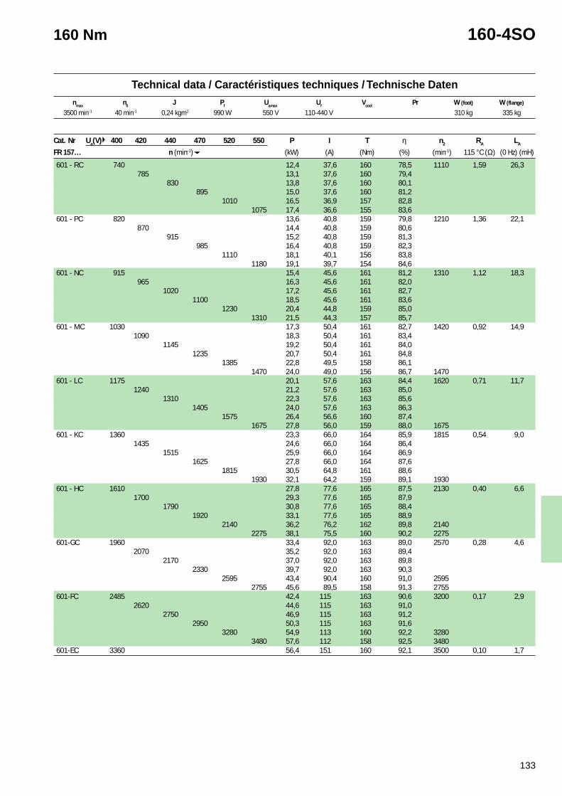
133
Technical data / Caractéristiques techniques / Technische Datennmax n0 J Pf Uamax Uf Vcool Pr W (foot) W (flange)
160 Nm 160-4SO
3500 min-1 40 min-1 0,24 kgm2 990 W 550 V 110-440 V 310 kg 335 kg
Cat. Nr Ua(V) 400 420 440 470 520 550 P I T η n2 RA LA
FR 157… n (min-1) (kW) (A) (Nm) (%) (min-1) 115 °C (Ω) (0 Hz) (mH)
601 - RC 740 12,4 37,6 160 78,5 1110 1,59 26,3785 13,1 37,6 160 79,4
830 13,8 37,6 160 80,1895 15,0 37,6 160 81,2
1010 16,5 36,9 157 82,81075 17,4 36,6 155 83,6
601 - PC 820 13,6 40,8 159 79,8 1210 1,36 22,1870 14,4 40,8 159 80,6
915 15,2 40,8 159 81,3985 16,4 40,8 159 82,3
1110 18,1 40,1 156 83,81180 19,1 39,7 154 84,6
601 - NC 915 15,4 45,6 161 81,2 1310 1,12 18,3965 16,3 45,6 161 82,0
1020 17,2 45,6 161 82,71100 18,5 45,6 161 83,6
1230 20,4 44,8 159 85,01310 21,5 44,3 157 85,7
601 - MC 1030 17,3 50,4 161 82,7 1420 0,92 14,91090 18,3 50,4 161 83,4
1145 19,2 50,4 161 84,01235 20,7 50,4 161 84,8
1385 22,8 49,5 158 86,11470 24,0 49,0 156 86,7 1470
601 - LC 1175 20,1 57,6 163 84,4 1620 0,71 11,71240 21,2 57,6 163 85,0
1310 22,3 57,6 163 85,61405 24,0 57,6 163 86,3
1575 26,4 56,6 160 87,41675 27,8 56,0 159 88,0 1675
601 - KC 1360 23,3 66,0 164 85,9 1815 0,54 9,01435 24,6 66,0 164 86,4
1515 25,9 66,0 164 86,91625 27,8 66,0 164 87,6
1815 30,5 64,8 161 88,61930 32,1 64,2 159 89,1 1930
601 - HC 1610 27,8 77,6 165 87,5 2130 0,40 6,61700 29,3 77,6 165 87,9
1790 30,8 77,6 165 88,41920 33,1 77,6 165 88,9
2140 36,2 76,2 162 89,8 21402275 38,1 75,5 160 90,2 2275
601-GC 1960 33,4 92,0 163 89,0 2570 0,28 4,62070 35,2 92,0 163 89,4
2170 37,0 92,0 163 89,82330 39,7 92,0 163 90,3
2595 43,4 90,4 160 91,0 25952755 45,6 89,5 158 91,3 2755
601-FC 2485 42,4 115 163 90,6 3200 0,17 2,92620 44,6 115 163 91,0
2750 46,9 115 163 91,22950 50,3 115 163 91,6
3280 54,9 113 160 92,2 32803480 57,6 112 158 92,5 3480
601-EC 3360 56,4 151 160 92,1 3500 0,10 1,7
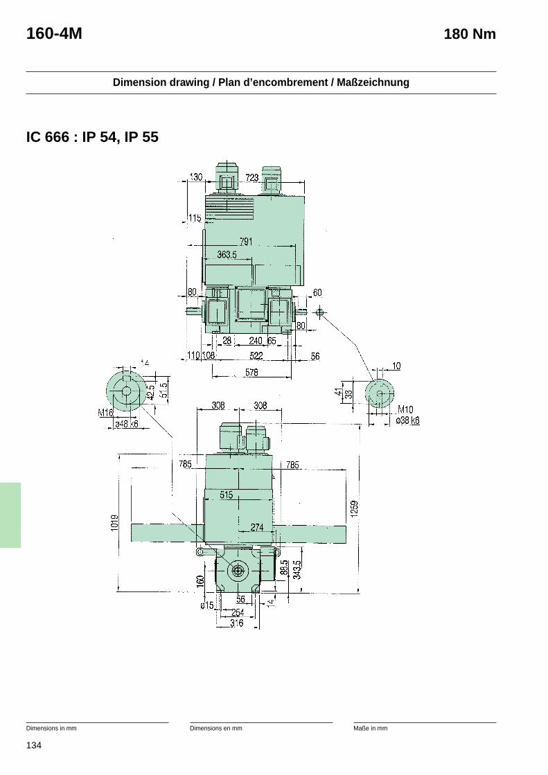
134
Dimension drawing / Plan d’encombrement / Maßzeichnung
Dimensions in mm Dimensions en mm Maße in mm
160-4M 180 Nm
IC 666 : IP 54, IP 55
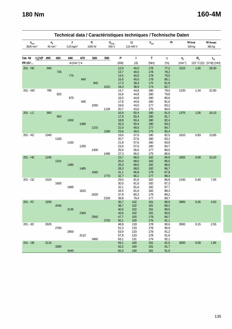
135
Technical data / Caractéristiques techniques / Technische Datennmax n0 J Pf Uamax Uf Vcool Pr W (foot) W (flange)
180 Nm 160-4M
3500 min-1 40 min-1 0,25 kgm2 1000 W 550 V 110-440 V 340 kg 365 kg
Cat. Nr Ua(V) 400 420 440 470 520 550 P I T η n2 RA LA
FR 157… n (min-1) (kW) (A) (Nm) (%) (min-1) 115 °C (Ω) (0 Hz) (mH)
201 - NC 690 12,9 40,0 178 77,2 1015 1,65 28,30735 13,7 40,0 178 78,2
775 14,5 40,0 178 79,0840 15,6 40,0 178 80,1
945 17,3 39,3 175 81,81010 18,3 38,9 174 82,7
201 - MC 780 14,7 44,8 180 79,0 1220 1,34 22,90825 15,6 44,8 180 79,8
875 16,5 44,8 180 80,6945 17,8 44,8 180 81,6
1060 19,6 44,0 177 83,21135 20,7 43,6 175 84,0
201 - LC 900 16,9 50,4 180 81,0 1375 1,05 18,10950 17,9 50,4 180 81,7
1000 18,9 50,4 180 82,41080 20,3 50,4 180 83,3
1215 22,4 49,5 177 84,71290 23,6 49,0 175 85,4
201 - KC 1040 19,6 57,6 180 82,5 1610 0,83 13,851100 20,7 57,6 180 83,2
1160 21,8 57,6 180 83,91250 23,5 57,6 180 84,7
1400 25,9 56,6 177 86,01490 27,3 56,0 175 86,6
201 - HC 1245 23,7 68,0 182 84,9 1825 0,58 10,201315 25,0 68,0 182 85,5
1385 26,3 68,0 182 86,01485 28,3 68,0 182 86,7
1665 31,1 66,8 179 87,81770 32,7 66,1 177 88,3
201 - GC 1520 29,0 81,6 182 86,8 2150 0,40 7,051605 30,5 81,6 182 87,3
1685 32,1 81,6 182 87,71810 34,5 81,6 182 88,3
2020 37,8 80,2 179 89,22150 39,8 79,4 177 89,7
201 - FC 1935 36,7 102 181 88,8 2865 0,26 4,502040 38,7 102 181 89,2
2145 40,6 102 181 89,52300 43,6 102 181 90,0
2560 47,7 100 178 90,72720 50,1 100 176 91,1
201 - EC 2625 48,8 133 178 90,6 3500 0,15 2,552760 51,3 133 178 90,9
2900 53,9 133 178 91,23110 57,8 133 178 91,6
3460 63,1 131 174 92,1201 - CB 3115 59,1 160 181 91,5 3500 0,09 1,85
3280 62,2 160 181 91,73440 65,3 160 181 91,9
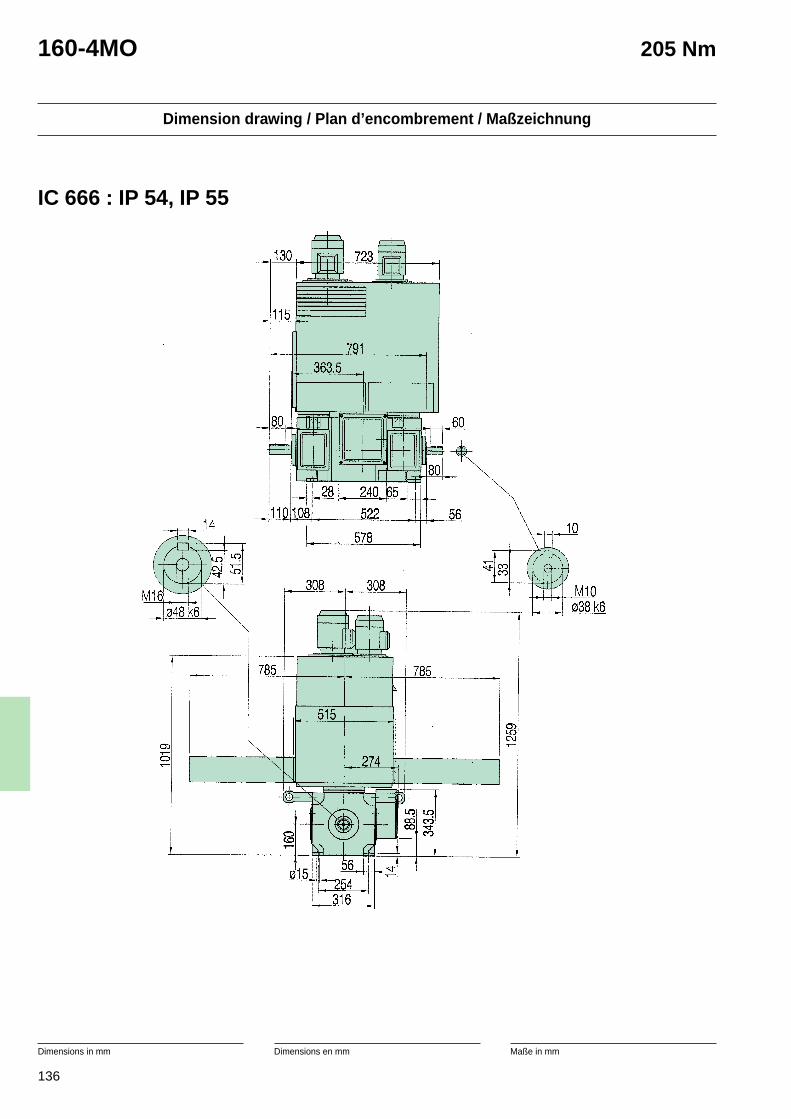
136
Dimension drawing / Plan d’encombrement / Maßzeichnung
Dimensions in mm Dimensions en mm Maße in mm
160-4MO 205 Nm
IC 666 : IP 54, IP 55
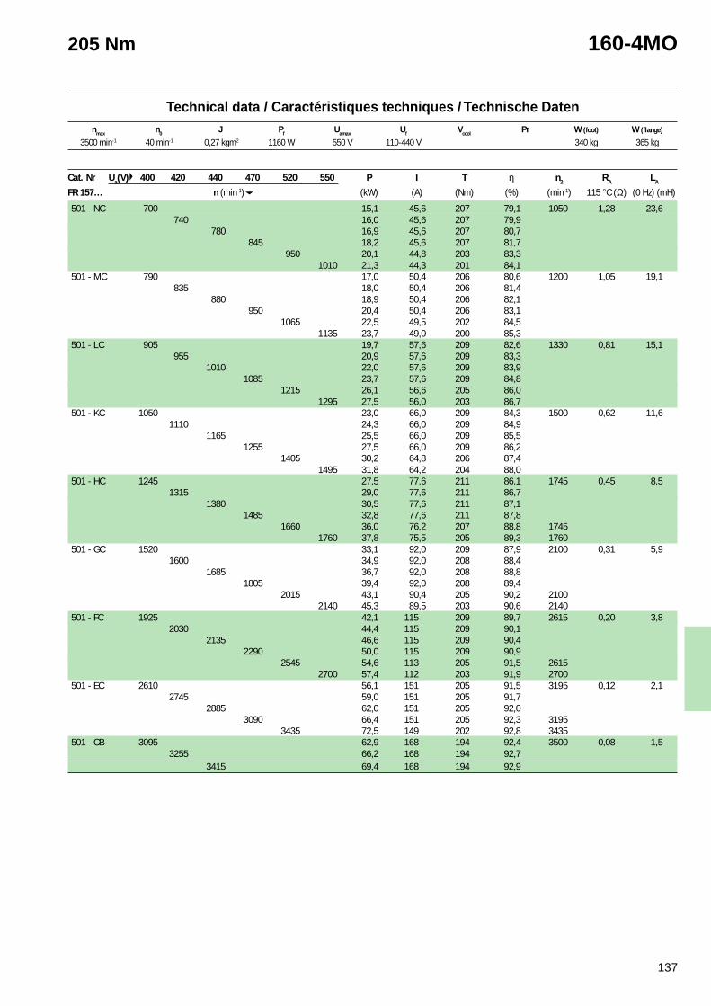
137
Technical data / Caractéristiques techniques / Technische Datennmax n0 J Pf Uamax Uf Vcool Pr W (foot) W (flange)
205 Nm 160-4MO
3500 min-1 40 min-1 0,27 kgm2 1160 W 550 V 110-440 V 340 kg 365 kg
Cat. Nr Ua(V) 400 420 440 470 520 550 P I T η n2 RA LA
FR 157… n (min-1) (kW) (A) (Nm) (%) (min-1) 115 °C (Ω) (0 Hz) (mH)
501 - NC 700 15,1 45,6 207 79,1 1050 1,28 23,6740 16,0 45,6 207 79,9
780 16,9 45,6 207 80,7845 18,2 45,6 207 81,7
950 20,1 44,8 203 83,31010 21,3 44,3 201 84,1
501 - MC 790 17,0 50,4 206 80,6 1200 1,05 19,1835 18,0 50,4 206 81,4
880 18,9 50,4 206 82,1950 20,4 50,4 206 83,1
1065 22,5 49,5 202 84,51135 23,7 49,0 200 85,3
501 - LC 905 19,7 57,6 209 82,6 1330 0,81 15,1955 20,9 57,6 209 83,3
1010 22,0 57,6 209 83,91085 23,7 57,6 209 84,8
1215 26,1 56,6 205 86,01295 27,5 56,0 203 86,7
501 - KC 1050 23,0 66,0 209 84,3 1500 0,62 11,61110 24,3 66,0 209 84,9
1165 25,5 66,0 209 85,51255 27,5 66,0 209 86,2
1405 30,2 64,8 206 87,41495 31,8 64,2 204 88,0
501 - HC 1245 27,5 77,6 211 86,1 1745 0,45 8,51315 29,0 77,6 211 86,7
1380 30,5 77,6 211 87,11485 32,8 77,6 211 87,8
1660 36,0 76,2 207 88,8 17451760 37,8 75,5 205 89,3 1760
501 - GC 1520 33,1 92,0 209 87,9 2100 0,31 5,91600 34,9 92,0 208 88,4
1685 36,7 92,0 208 88,81805 39,4 92,0 208 89,4
2015 43,1 90,4 205 90,2 21002140 45,3 89,5 203 90,6 2140
501 - FC 1925 42,1 115 209 89,7 2615 0,20 3,82030 44,4 115 209 90,1
2135 46,6 115 209 90,42290 50,0 115 209 90,9
2545 54,6 113 205 91,5 26152700 57,4 112 203 91,9 2700
501 - EC 2610 56,1 151 205 91,5 3195 0,12 2,12745 59,0 151 205 91,7
2885 62,0 151 205 92,03090 66,4 151 205 92,3 3195
3435 72,5 149 202 92,8 3435501 - CB 3095 62,9 168 194 92,4 3500 0,08 1,5
3255 66,2 168 194 92,73415 69,4 168 194 92,9

138
Dimension drawing / Plan d’encombrement / Maßzeichnung
Dimensions in mm Dimensions en mm Maße in mm
160-4L 235 Nm
IC 666 : IP 54, IP 55

139
Technical data / Caractéristiques techniques / Technische Datennmax n0 J Pf Uamax Uf Vcool Pr W (foot) W (flange)
235 Nm 160-4L
3500 min-1 40 min-1 0,31 kgm2 1120 W 550 V 110-440 V 385 kg 410 kg
Cat. Nr Ua(V) 400 420 440 470 520 550 P I T η n2 RA LA
FR 157… n (min-1) (kW) (A) (Nm) (%) (min-1) 115 °C (Ω) (0 Hz) (mH)
101 - LC 670 16,4 50,4 234 78,3 1090 1,24 22,60710 17,4 50,4 234 79,2
750 18,4 50,4 234 80,0810 19,8 50,4 234 81,0
915 21,9 49,5 230 82,7975 23,2 49,0 228 83,5
101 - KC 780 19,1 57,6 234 80,2 1275 0,98 17,30825 20,2 57,6 234 81,0
870 21,3 57,6 234 81,7940 23,0 57,6 234 82,7
1055 25,4 56,6 230 84,11125 26,8 56,0 227 84,9
101 - HC 935 23,2 68,0 237 82,9 1435 0,69 12,70990 24,5 68,0 237 83,6
1045 25,8 68,0 237 84,21125 27,8 68,0 237 85,0
1260 30,6 66,8 233 86,21340 32,3 66,1 230 86,8
101 - GC 1150 28,4 81,6 237 85,1 1685 0,48 8,851210 30,0 81,6 237 85,7
1275 31,6 81,6 237 86,21370 34,0 81,6 237 86,9
1535 37,3 80,2 233 87,91630 39,3 79,4 230 88,4
101 - FC 1465 36,2 102 236 87,4 2260 0,31 5,651545 38,2 102 236 87,8
1625 40,1 102 236 88,21745 43,1 102 236 88,8
1950 47,2 99,8 232 89,62070 49,6 98,8 229 90,0
101 - EC 1995 48,2 133 231 89,5 3000 0,18 3,202100 50,8 133 231 89,9
2210 53,4 133 231 90,22370 57,2 133 231 90,6
2635 62,6 131 227 91,22800 65,7 129 224 92,6
101 - CB 2375 58,9 160 237 91,0 3440 0,11 2,302500 62,0 160 237 91,3
2625 65,1 160 237 91,52815 69,8 160 237 91,9
3130 76,1 157 233 92,33315 79,9 156 230 92,6
101 - BB 3000 69,5 187 221 91,9 3500 0,08 1,503155 73,1 187 221 92,1
3310 76,7 187 221 92,3
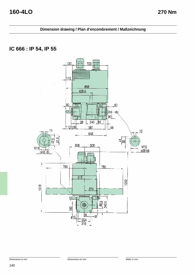
140
Dimension drawing / Plan d’encombrement / Maßzeichnung
Dimensions in mm Dimensions en mm Maße in mm
160-4LO 270 Nm
IC 666 : IP 54, IP 55
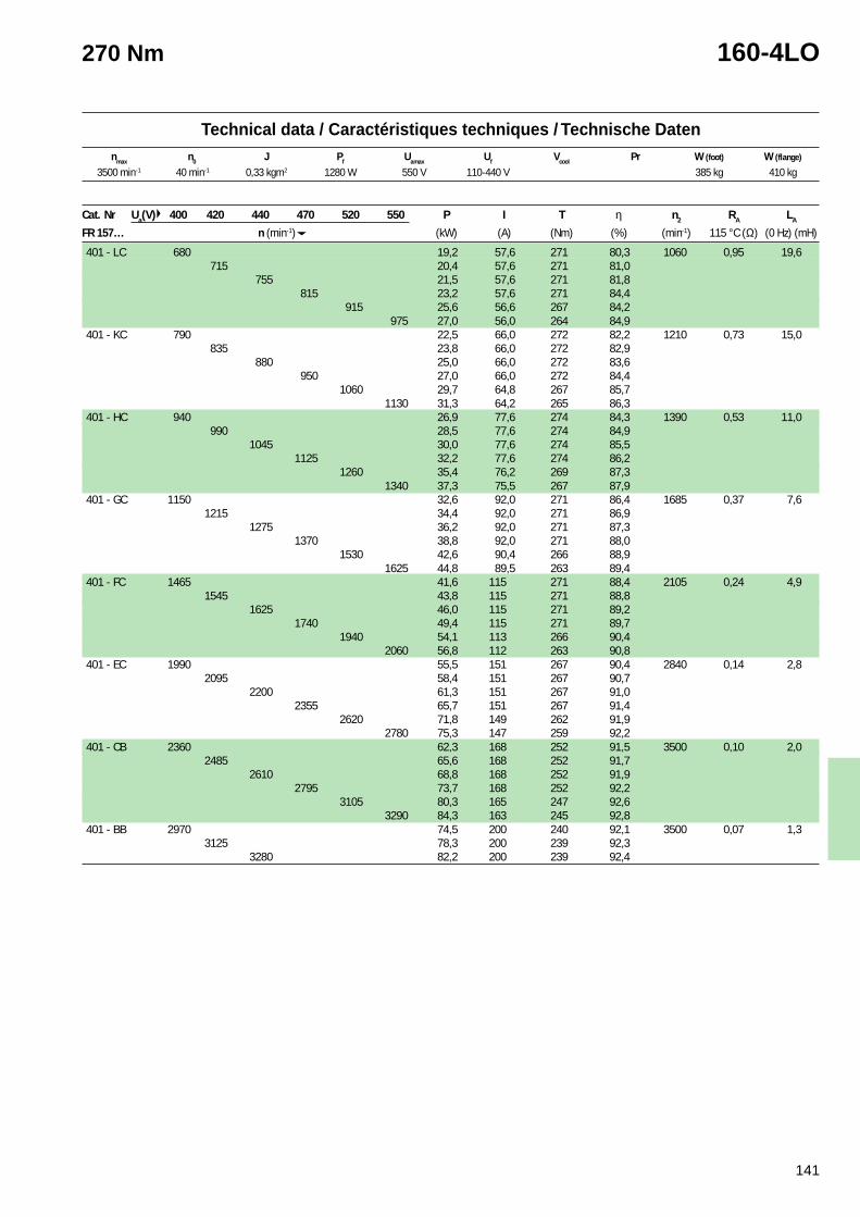
141
Technical data / Caractéristiques techniques / Technische Datennmax n0 J Pf Uamax Uf Vcool Pr W (foot) W (flange)
270 Nm 160-4LO
3500 min-1 40 min-1 0,33 kgm2 1280 W 550 V 110-440 V 385 kg 410 kg
Cat. Nr Ua(V) 400 420 440 470 520 550 P I T η n2 RA LA
FR 157… n (min-1) (kW) (A) (Nm) (%) (min-1) 115 °C (Ω) (0 Hz) (mH)
401 - LC 680 19,2 57,6 271 80,3 1060 0,95 19,6715 20,4 57,6 271 81,0
755 21,5 57,6 271 81,8815 23,2 57,6 271 84,4
915 25,6 56,6 267 84,2975 27,0 56,0 264 84,9
401 - KC 790 22,5 66,0 272 82,2 1210 0,73 15,0835 23,8 66,0 272 82,9
880 25,0 66,0 272 83,6950 27,0 66,0 272 84,4
1060 29,7 64,8 267 85,71130 31,3 64,2 265 86,3
401 - HC 940 26,9 77,6 274 84,3 1390 0,53 11,0990 28,5 77,6 274 84,9
1045 30,0 77,6 274 85,51125 32,2 77,6 274 86,2
1260 35,4 76,2 269 87,31340 37,3 75,5 267 87,9
401 - GC 1150 32,6 92,0 271 86,4 1685 0,37 7,61215 34,4 92,0 271 86,9
1275 36,2 92,0 271 87,31370 38,8 92,0 271 88,0
1530 42,6 90,4 266 88,91625 44,8 89,5 263 89,4
401 - FC 1465 41,6 115 271 88,4 2105 0,24 4,91545 43,8 115 271 88,8
1625 46,0 115 271 89,21740 49,4 115 271 89,7
1940 54,1 113 266 90,42060 56,8 112 263 90,8
401 - EC 1990 55,5 151 267 90,4 2840 0,14 2,82095 58,4 151 267 90,7
2200 61,3 151 267 91,02355 65,7 151 267 91,4
2620 71,8 149 262 91,92780 75,3 147 259 92,2
401 - CB 2360 62,3 168 252 91,5 3500 0,10 2,02485 65,6 168 252 91,7
2610 68,8 168 252 91,92795 73,7 168 252 92,2
3105 80,3 165 247 92,63290 84,3 163 245 92,8
401 - BB 2970 74,5 200 240 92,1 3500 0,07 1,33125 78,3 200 239 92,3
3280 82,2 200 239 92,4
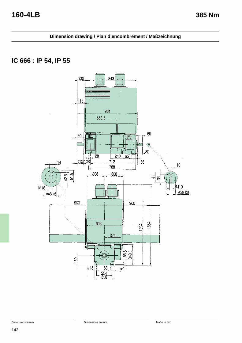
142
Dimension drawing / Plan d’encombrement / Maßzeichnung
Dimensions in mm Dimensions en mm Maße in mm
160-4LB 385 Nm
IC 666 : IP 54, IP 55
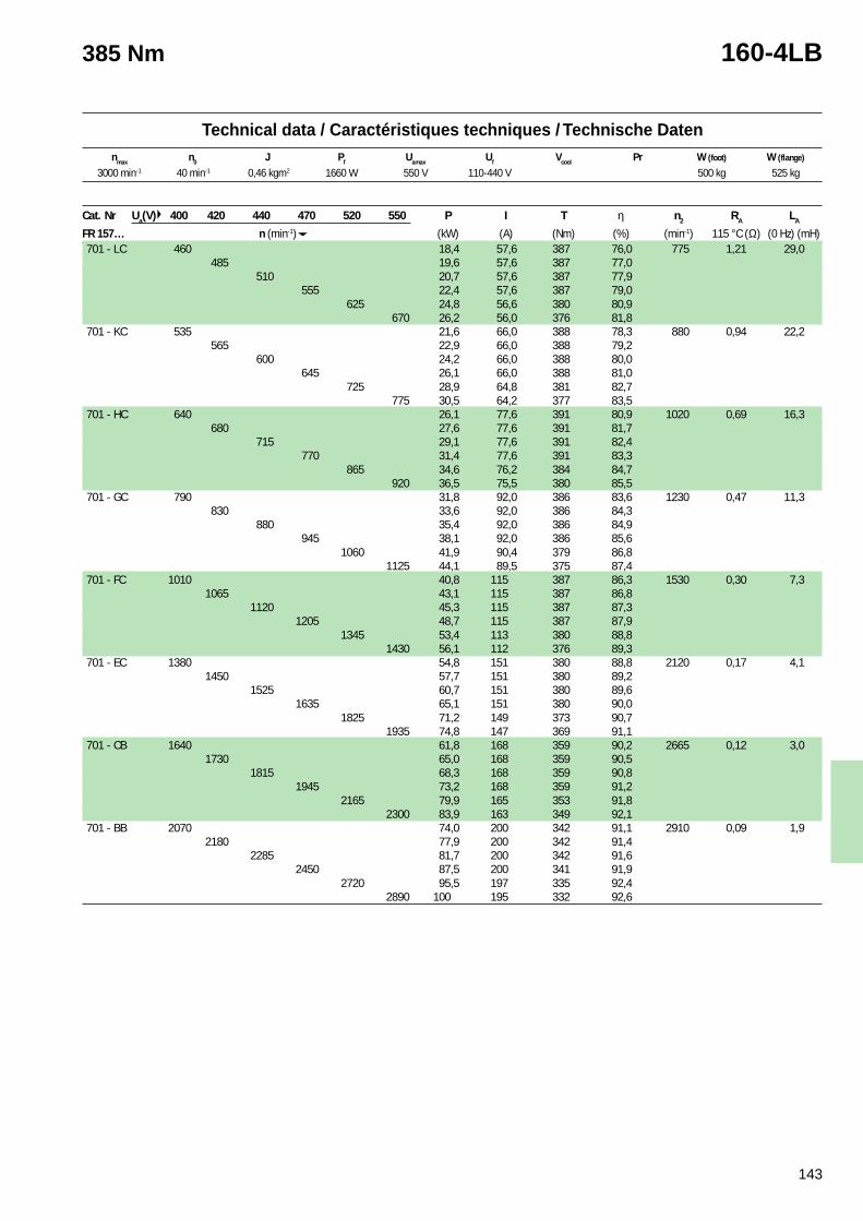
143
Technical data / Caractéristiques techniques / Technische Datennmax n0 J Pf Uamax Uf Vcool Pr W (foot) W (flange)
385 Nm 160-4LB
3000 min-1 40 min-1 0,46 kgm2 1660 W 550 V 110-440 V 500 kg 525 kg
Cat. Nr Ua(V) 400 420 440 470 520 550 P I T η n2 RA LA
FR 157… n (min-1) (kW) (A) (Nm) (%) (min-1) 115 °C (Ω) (0 Hz) (mH)701 - LC 460 18,4 57,6 387 76,0 775 1,21 29,0
485 19,6 57,6 387 77,0510 20,7 57,6 387 77,9
555 22,4 57,6 387 79,0625 24,8 56,6 380 80,9
670 26,2 56,0 376 81,8701 - KC 535 21,6 66,0 388 78,3 880 0,94 22,2
565 22,9 66,0 388 79,2600 24,2 66,0 388 80,0
645 26,1 66,0 388 81,0725 28,9 64,8 381 82,7
775 30,5 64,2 377 83,5701 - HC 640 26,1 77,6 391 80,9 1020 0,69 16,3
680 27,6 77,6 391 81,7715 29,1 77,6 391 82,4
770 31,4 77,6 391 83,3865 34,6 76,2 384 84,7
920 36,5 75,5 380 85,5701 - GC 790 31,8 92,0 386 83,6 1230 0,47 11,3
830 33,6 92,0 386 84,3880 35,4 92,0 386 84,9
945 38,1 92,0 386 85,61060 41,9 90,4 379 86,8
1125 44,1 89,5 375 87,4701 - FC 1010 40,8 115 387 86,3 1530 0,30 7,3
1065 43,1 115 387 86,81120 45,3 115 387 87,3
1205 48,7 115 387 87,91345 53,4 113 380 88,8
1430 56,1 112 376 89,3701 - EC 1380 54,8 151 380 88,8 2120 0,17 4,1
1450 57,7 151 380 89,21525 60,7 151 380 89,6
1635 65,1 151 380 90,01825 71,2 149 373 90,7
1935 74,8 147 369 91,1701 - CB 1640 61,8 168 359 90,2 2665 0,12 3,0
1730 65,0 168 359 90,51815 68,3 168 359 90,8
1945 73,2 168 359 91,22165 79,9 165 353 91,8
2300 83,9 163 349 92,1701 - BB 2070 74,0 200 342 91,1 2910 0,09 1,9
2180 77,9 200 342 91,42285 81,7 200 342 91,6
2450 87,5 200 341 91,92720 95,5 197 335 92,4
2890 100 195 332 92,6
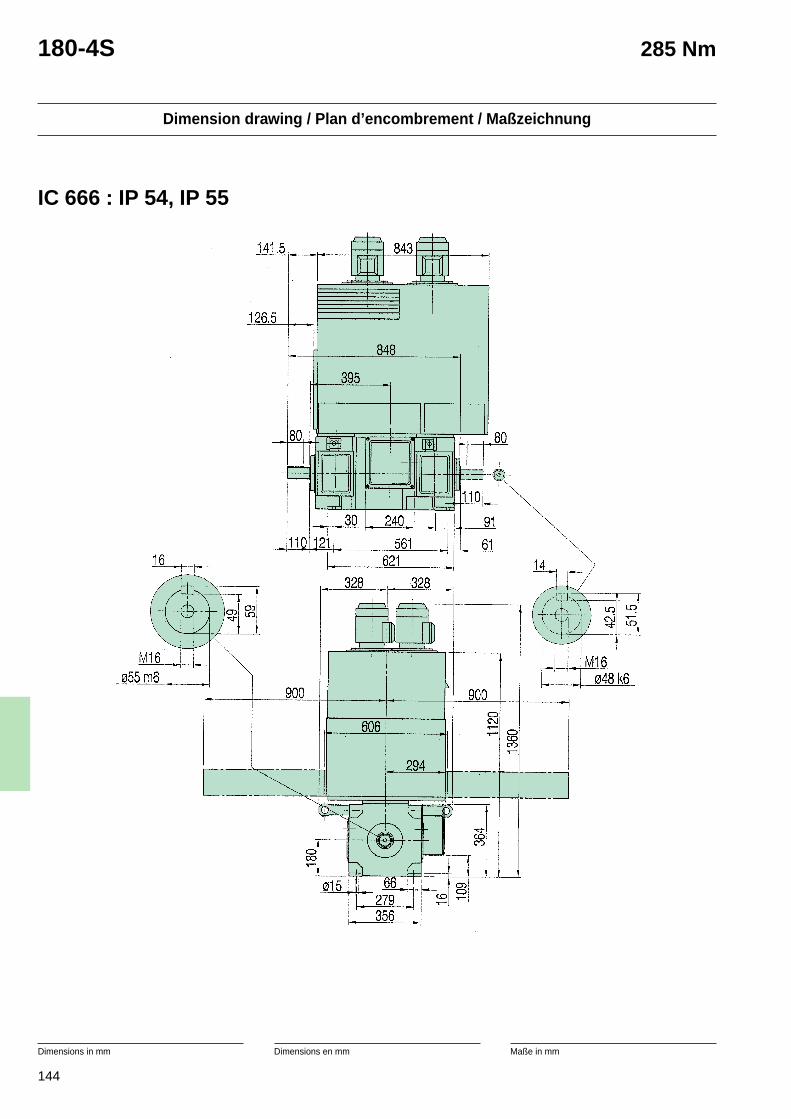
144
Dimension drawing / Plan d’encombrement / Maßzeichnung
Dimensions in mm Dimensions en mm Maße in mm
180-4S 285 Nm
IC 666 : IP 54, IP 55
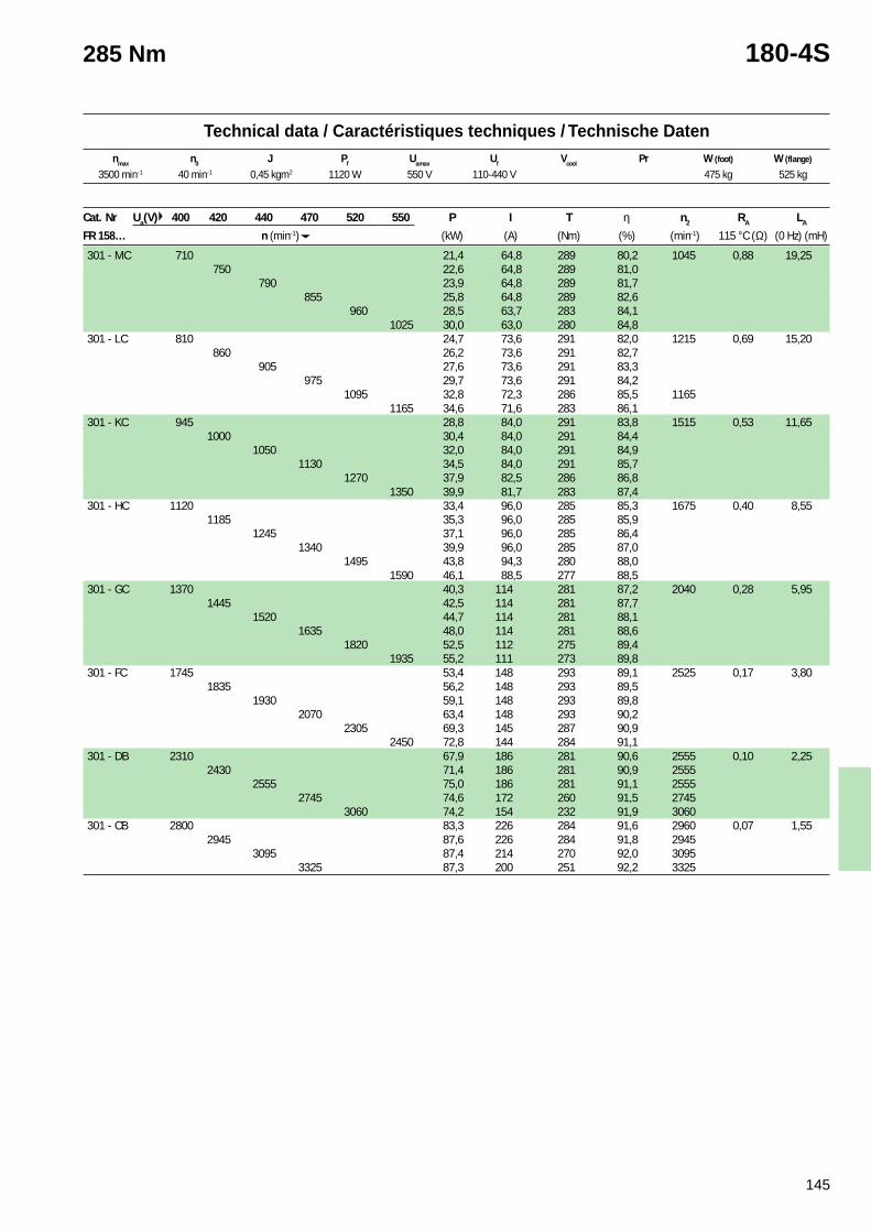
145
Technical data / Caractéristiques techniques / Technische Datennmax n0 J Pf Uamax Uf Vcool Pr W (foot) W (flange)
285 Nm 180-4S
3500 min-1 40 min-1 0,45 kgm2 1120 W 550 V 110-440 V 475 kg 525 kg
Cat. Nr Ua(V) 400 420 440 470 520 550 P I T η n2 RA LA
FR 158… n (min-1) (kW) (A) (Nm) (%) (min-1) 115 °C (Ω) (0 Hz) (mH)
301 - MC 710 21,4 64,8 289 80,2 1045 0,88 19,25750 22,6 64,8 289 81,0
790 23,9 64,8 289 81,7855 25,8 64,8 289 82,6
960 28,5 63,7 283 84,11025 30,0 63,0 280 84,8
301 - LC 810 24,7 73,6 291 82,0 1215 0,69 15,20860 26,2 73,6 291 82,7
905 27,6 73,6 291 83,3975 29,7 73,6 291 84,2
1095 32,8 72,3 286 85,5 11651165 34,6 71,6 283 86,1
301 - KC 945 28,8 84,0 291 83,8 1515 0,53 11,651000 30,4 84,0 291 84,4
1050 32,0 84,0 291 84,91130 34,5 84,0 291 85,7
1270 37,9 82,5 286 86,81350 39,9 81,7 283 87,4
301 - HC 1120 33,4 96,0 285 85,3 1675 0,40 8,551185 35,3 96,0 285 85,9
1245 37,1 96,0 285 86,41340 39,9 96,0 285 87,0
1495 43,8 94,3 280 88,01590 46,1 88,5 277 88,5
301 - GC 1370 40,3 114 281 87,2 2040 0,28 5,951445 42,5 114 281 87,7
1520 44,7 114 281 88,11635 48,0 114 281 88,6
1820 52,5 112 275 89,41935 55,2 111 273 89,8
301 - FC 1745 53,4 148 293 89,1 2525 0,17 3,801835 56,2 148 293 89,5
1930 59,1 148 293 89,82070 63,4 148 293 90,2
2305 69,3 145 287 90,92450 72,8 144 284 91,1
301 - DB 2310 67,9 186 281 90,6 2555 0,10 2,252430 71,4 186 281 90,9 2555
2555 75,0 186 281 91,1 25552745 74,6 172 260 91,5 2745
3060 74,2 154 232 91,9 3060301 - CB 2800 83,3 226 284 91,6 2960 0,07 1,55
2945 87,6 226 284 91,8 29453095 87,4 214 270 92,0 3095
3325 87,3 200 251 92,2 3325
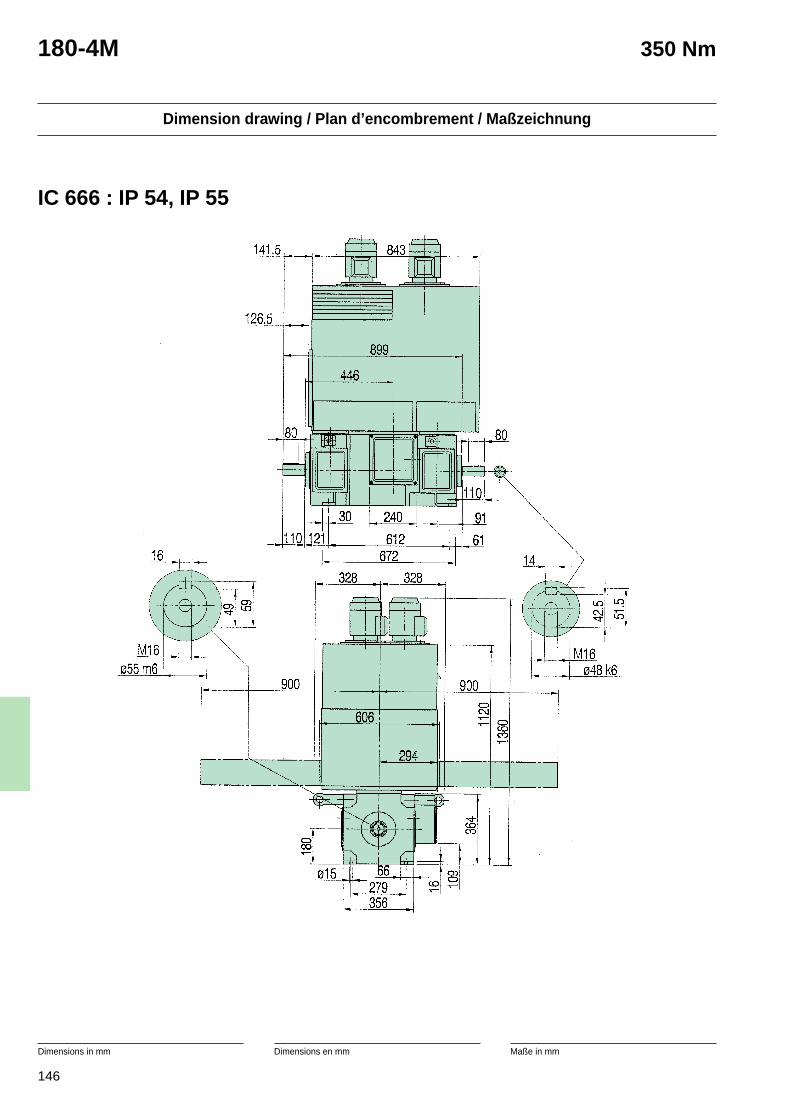
146
Dimension drawing / Plan d’encombrement / Maßzeichnung
Dimensions in mm Dimensions en mm Maße in mm
180-4M 350 Nm
IC 666 : IP 54, IP 55
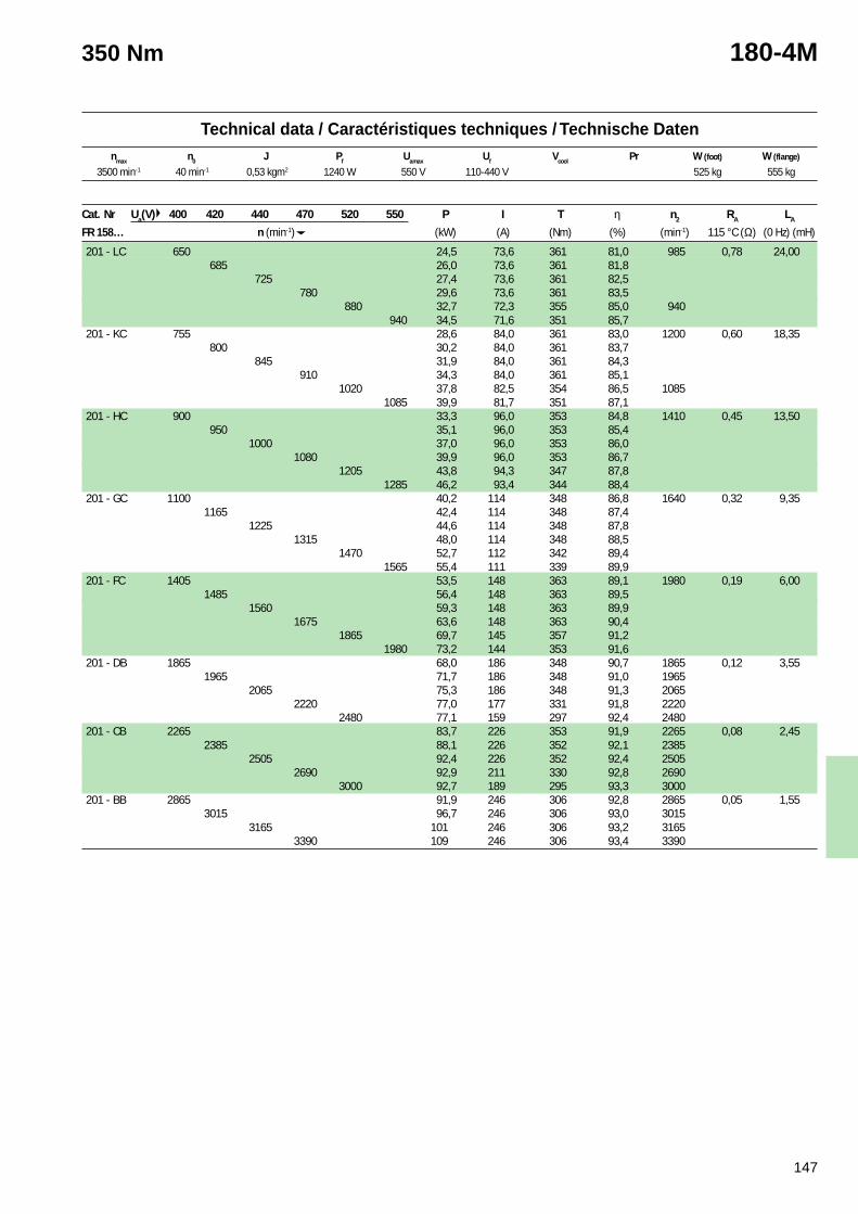
147
Technical data / Caractéristiques techniques / Technische Datennmax n0 J Pf Uamax Uf Vcool Pr W (foot) W (flange)
350 Nm 180-4M
3500 min-1 40 min-1 0,53 kgm2 1240 W 550 V 110-440 V 525 kg 555 kg
Cat. Nr Ua(V) 400 420 440 470 520 550 P I T η n2 RA LA
FR 158… n (min-1) (kW) (A) (Nm) (%) (min-1) 115 °C (Ω) (0 Hz) (mH)
201 - LC 650 24,5 73,6 361 81,0 985 0,78 24,00685 26,0 73,6 361 81,8
725 27,4 73,6 361 82,5780 29,6 73,6 361 83,5
880 32,7 72,3 355 85,0 940940 34,5 71,6 351 85,7
201 - KC 755 28,6 84,0 361 83,0 1200 0,60 18,35800 30,2 84,0 361 83,7
845 31,9 84,0 361 84,3910 34,3 84,0 361 85,1
1020 37,8 82,5 354 86,5 10851085 39,9 81,7 351 87,1
201 - HC 900 33,3 96,0 353 84,8 1410 0,45 13,50950 35,1 96,0 353 85,4
1000 37,0 96,0 353 86,01080 39,9 96,0 353 86,7
1205 43,8 94,3 347 87,81285 46,2 93,4 344 88,4
201 - GC 1100 40,2 114 348 86,8 1640 0,32 9,351165 42,4 114 348 87,4
1225 44,6 114 348 87,81315 48,0 114 348 88,5
1470 52,7 112 342 89,41565 55,4 111 339 89,9
201 - FC 1405 53,5 148 363 89,1 1980 0,19 6,001485 56,4 148 363 89,5
1560 59,3 148 363 89,91675 63,6 148 363 90,4
1865 69,7 145 357 91,21980 73,2 144 353 91,6
201 - DB 1865 68,0 186 348 90,7 1865 0,12 3,551965 71,7 186 348 91,0 1965
2065 75,3 186 348 91,3 20652220 77,0 177 331 91,8 2220
2480 77,1 159 297 92,4 2480201 - CB 2265 83,7 226 353 91,9 2265 0,08 2,45
2385 88,1 226 352 92,1 23852505 92,4 226 352 92,4 2505
2690 92,9 211 330 92,8 26903000 92,7 189 295 93,3 3000
201 - BB 2865 91,9 246 306 92,8 2865 0,05 1,553015 96,7 246 306 93,0 3015
3165 101 246 306 93,2 31653390 109 246 306 93,4 3390
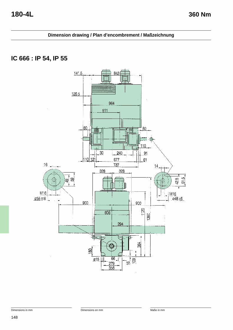
148
Dimension drawing / Plan d’encombrement / Maßzeichnung
Dimensions in mm Dimensions en mm Maße in mm
180-4L 360 Nm
IC 666 : IP 54, IP 55
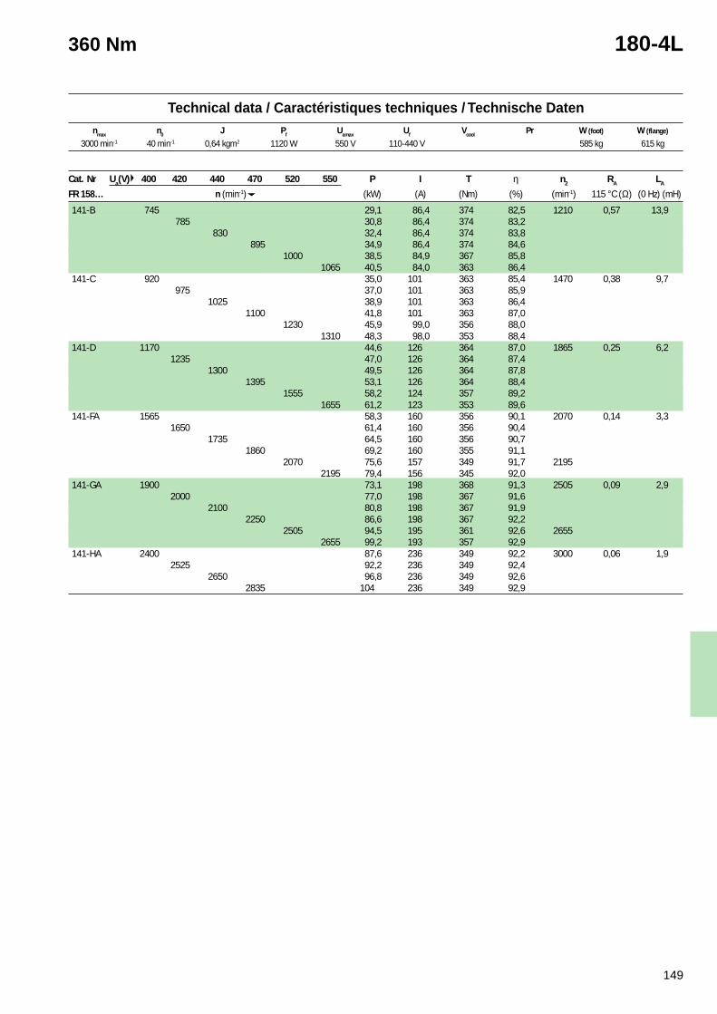
149
Technical data / Caractéristiques techniques / Technische Datennmax n0 J Pf Uamax Uf Vcool Pr W (foot) W (flange)
360 Nm 180-4L
3000 min-1 40 min-1 0,64 kgm2 1120 W 550 V 110-440 V 585 kg 615 kg
Cat. Nr Ua(V) 400 420 440 470 520 550 P I T η n2 RA LA
FR 158… n (min-1) (kW) (A) (Nm) (%) (min-1) 115 °C (Ω) (0 Hz) (mH)
141-B 745 29,1 86,4 374 82,5 1210 0,57 13,9785 30,8 86,4 374 83,2
830 32,4 86,4 374 83,8895 34,9 86,4 374 84,6
1000 38,5 84,9 367 85,81065 40,5 84,0 363 86,4
141-C 920 35,0 101 363 85,4 1470 0,38 9,7975 37,0 101 363 85,9
1025 38,9 101 363 86,41100 41,8 101 363 87,0
1230 45,9 99,0 356 88,01310 48,3 98,0 353 88,4
141-D 1170 44,6 126 364 87,0 1865 0,25 6,21235 47,0 126 364 87,4
1300 49,5 126 364 87,81395 53,1 126 364 88,4
1555 58,2 124 357 89,21655 61,2 123 353 89,6
141-FA 1565 58,3 160 356 90,1 2070 0,14 3,31650 61,4 160 356 90,4
1735 64,5 160 356 90,71860 69,2 160 355 91,1
2070 75,6 157 349 91,7 21952195 79,4 156 345 92,0
141-GA 1900 73,1 198 368 91,3 2505 0,09 2,92000 77,0 198 367 91,6
2100 80,8 198 367 91,92250 86,6 198 367 92,2
2505 94,5 195 361 92,6 26552655 99,2 193 357 92,9
141-HA 2400 87,6 236 349 92,2 3000 0,06 1,92525 92,2 236 349 92,4
2650 96,8 236 349 92,62835 104 236 349 92,9
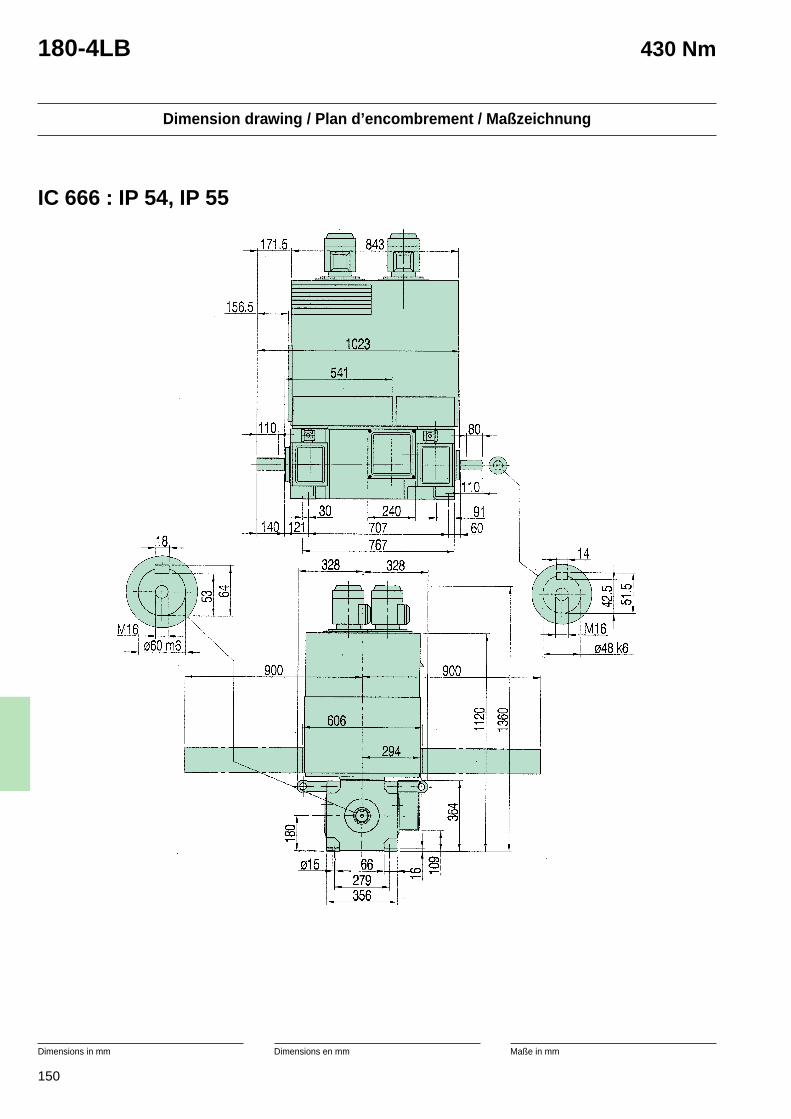
150
Dimension drawing / Plan d’encombrement / Maßzeichnung
Dimensions in mm Dimensions en mm Maße in mm
180-4LB 430 Nm
IC 666 : IP 54, IP 55
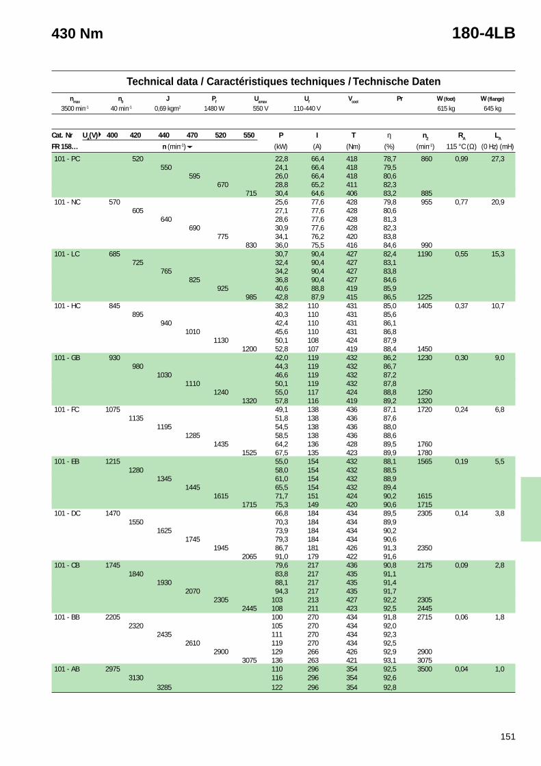
151
Technical data / Caractéristiques techniques / Technische Datennmax n0 J Pf Uamax Uf Vcool Pr W (foot) W (flange)
430 Nm 180-4LB
3500 min-1 40 min-1 0,69 kgm2 1480 W 550 V 110-440 V 615 kg 645 kg
Cat. Nr Ua(V) 400 420 440 470 520 550 P I T η n2 RA LA
FR 158… n (min-1) (kW) (A) (Nm) (%) (min-1) 115 °C (Ω) (0 Hz) (mH)
101 - PC 520 22,8 66,4 418 78,7 860 0,99 27,3550 24,1 66,4 418 79,5
595 26,0 66,4 418 80,6670 28,8 65,2 411 82,3
715 30,4 64,6 406 83,2 885101 - NC 570 25,6 77,6 428 79,8 955 0,77 20,9
605 27,1 77,6 428 80,6640 28,6 77,6 428 81,3
690 30,9 77,6 428 82,3775 34,1 76,2 420 83,8
830 36,0 75,5 416 84,6 990101 - LC 685 30,7 90,4 427 82,4 1190 0,55 15,3
725 32,4 90,4 427 83,1765 34,2 90,4 427 83,8
825 36,8 90,4 427 84,6925 40,6 88,8 419 85,9
985 42,8 87,9 415 86,5 1225101 - HC 845 38,2 110 431 85,0 1405 0,37 10,7
895 40,3 110 431 85,6940 42,4 110 431 86,1
1010 45,6 110 431 86,81130 50,1 108 424 87,9
1200 52,8 107 419 88,4 1450101 - GB 930 42,0 119 432 86,2 1230 0,30 9,0
980 44,3 119 432 86,71030 46,6 119 432 87,2
1110 50,1 119 432 87,81240 55,0 117 424 88,8 1250
1320 57,8 116 419 89,2 1320101 - FC 1075 49,1 138 436 87,1 1720 0,24 6,8
1135 51,8 138 436 87,61195 54,5 138 436 88,0
1285 58,5 138 436 88,61435 64,2 136 428 89,5 1760
1525 67,5 135 423 89,9 1780101 - EB 1215 55,0 154 432 88,1 1565 0,19 5,5
1280 58,0 154 432 88,51345 61,0 154 432 88,9
1445 65,5 154 432 89,41615 71,7 151 424 90,2 1615
1715 75,3 149 420 90,6 1715101 - DC 1470 66,8 184 434 89,5 2305 0,14 3,8
1550 70,3 184 434 89,91625 73,9 184 434 90,2
1745 79,3 184 434 90,61945 86,7 181 426 91,3 2350
2065 91,0 179 422 91,6101 - CB 1745 79,6 217 436 90,8 2175 0,09 2,8
1840 83,8 217 435 91,11930 88,1 217 435 91,4
2070 94,3 217 435 91,72305 103 213 427 92,2 2305
2445 108 211 423 92,5 2445101 - BB 2205 100 270 434 91,8 2715 0,06 1,8
2320 105 270 434 92,02435 111 270 434 92,3
2610 119 270 434 92,52900 129 266 426 92,9 2900
3075 136 263 421 93,1 3075101 - AB 2975 110 296 354 92,5 3500 0,04 1,0
3130 116 296 354 92,63285 122 296 354 92,8
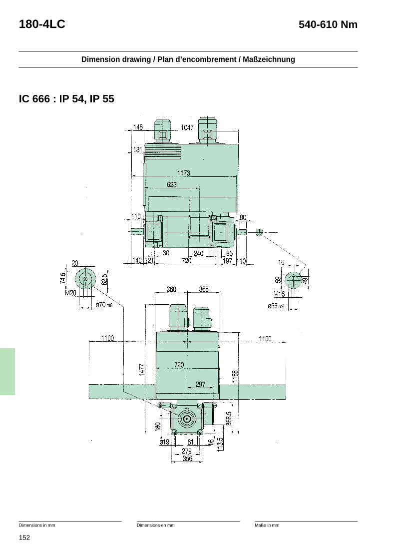
152
Dimension drawing / Plan d’encombrement / Maßzeichnung
Dimensions in mm Dimensions en mm Maße in mm
180-4LC 540-610 Nm
IC 666 : IP 54, IP 55
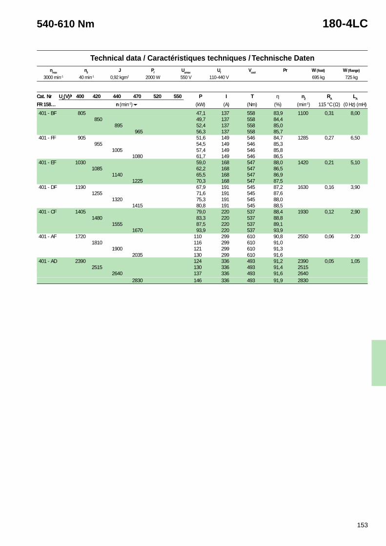
153
Technical data / Caractéristiques techniques / Technische Datennmax n0 J Pf Uamax Uf Vcool Pr W (foot) W (flange)
540-610 Nm 180-4LC
3000 min-1 40 min-1 0,92 kgm2 2000 W 550 V 110-440 V 695 kg 725 kg
Cat. Nr Ua(V) 400 420 440 470 520 550 P I T η n2 RA LA
FR 158… n (min-1) (kW) (A) (Nm) (%) (min-1) 115 °C (Ω) (0 Hz) (mH)
401 - BF 805 47,1 137 558 83,9 1100 0,31 8,00850 49,7 137 558 84,4
895 52,4 137 558 85,0965 56,3 137 558 85,7
401 - FF 905 51,6 149 546 84,7 1285 0,27 6,50955 54,5 149 546 85,3
1005 57,4 149 546 85,81080 61,7 149 546 86,5
401 - EF 1030 59,0 168 547 88,0 1420 0,21 5,101085 62,2 168 547 86,5
1140 65,5 168 547 86,91225 70,3 168 547 87,5
401 - DF 1190 67,9 191 545 87,2 1630 0,16 3,901255 71,6 191 545 87,6
1320 75,3 191 545 88,01415 80,8 191 545 88,5
401 - CF 1405 79,0 220 537 88,4 1930 0,12 2,901480 83,3 220 537 88,8
1555 87,5 220 537 89,11670 93,9 220 537 93,9
401 - AF 1720 110 299 610 90,8 2550 0,06 2,001810 116 299 610 91,0
1900 121 299 610 91,32035 130 299 610 91,6
401 - AD 2390 124 336 493 91,2 2390 0,05 1,052515 130 336 493 91,4 2515
2640 137 336 493 91,6 26402830 146 336 493 91,9 2830
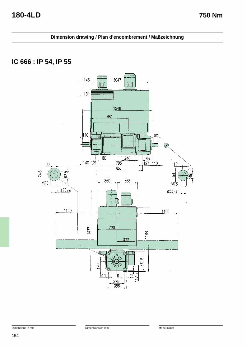
154
Dimension drawing / Plan d’encombrement / Maßzeichnung
Dimensions in mm Dimensions en mm Maße in mm
180-4LD 750 Nm
IC 666 : IP 54, IP 55
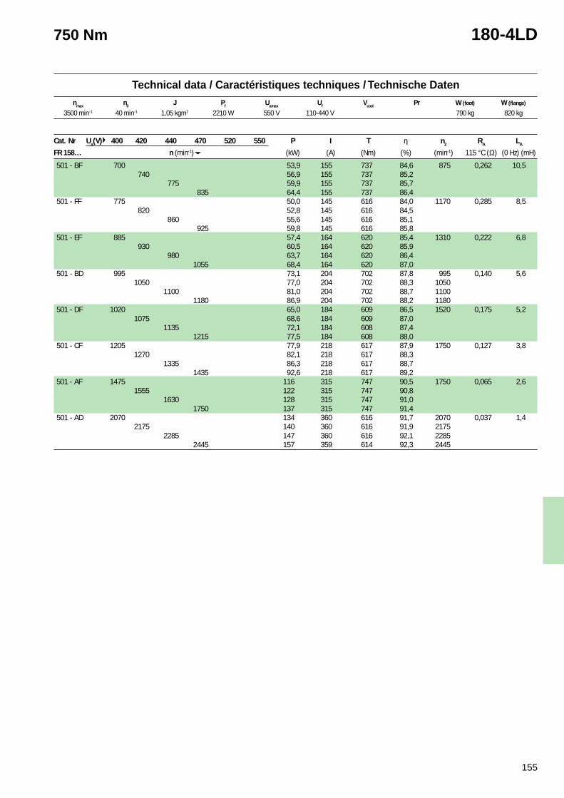
155
Technical data / Caractéristiques techniques / Technische Datennmax n0 J Pf Uamax Uf Vcool Pr W (foot) W (flange)
750 Nm 180-4LD
3500 min-1 40 min-1 1,05 kgm2 2210 W 550 V 110-440 V 790 kg 820 kg
Cat. Nr Ua(V) 400 420 440 470 520 550 P I T η n2 RA LA
FR 158… n (min-1) (kW) (A) (Nm) (%) (min-1) 115 °C (Ω) (0 Hz) (mH)
501 - BF 700 53,9 155 737 84,6 875 0,262 10,5740 56,9 155 737 85,2
775 59,9 155 737 85,7835 64,4 155 737 86,4
501 - FF 775 50,0 145 616 84,0 1170 0,285 8,5820 52,8 145 616 84,5
860 55,6 145 616 85,1925 59,8 145 616 85,8
501 - EF 885 57,4 164 620 85,4 1310 0,222 6,8930 60,5 164 620 85,9
980 63,7 164 620 86,41055 68,4 164 620 87,0
501 - BD 995 73,1 204 702 87,8 995 0,140 5,61050 77,0 204 702 88,3 1050
1100 81,0 204 702 88,7 11001180 86,9 204 702 88,2 1180
501 - DF 1020 65,0 184 609 86,5 1520 0,175 5,21075 68,6 184 609 87,0
1135 72,1 184 608 87,41215 77,5 184 608 88,0
501 - CF 1205 77,9 218 617 87,9 1750 0,127 3,81270 82,1 218 617 88,3
1335 86,3 218 617 88,71435 92,6 218 617 89,2
501 - AF 1475 116 315 747 90,5 1750 0,065 2,61555 122 315 747 90,8
1630 128 315 747 91,01750 137 315 747 91,4
501 - AD 2070 134 360 616 91,7 2070 0,037 1,42175 140 360 616 91,9 2175
2285 147 360 616 92,1 22852445 157 359 614 92,3 2445
156
Motors in stock
The motors indicated with the sign *in the electrical tables are availablefrom stock and can therefore bedelivered promptly. The stock motorsare available according to followingspecification. Motor fan, standardtachogenerator and coupling can,however be fitted on request beforethe delivery.
• IM 1001, IP 23, IC 17, designedfor cooling air intake at either D-or N-end (when possible, coolingair intake should always be at theD-end of DMP motors).
• Cylindrical roller bearing on D-end.
• Terminal box on right.
• Balanced with half key.
• Temperature sensor of bimetaltype.
• Thermistor.
• Plates and documents in English.
• Rating data as standard motorsbut field weakening is onlyallowed up to 25 % overspeed forstock motors.
• Stock motors have a parallel-serial connection suitable for170-180-190/340-360-380 voltson excitation.
• Stock motors are withtropicalisation.
Moteurs en stock
Les moteurs repérés par le signe *dans les tableaux électriques sontdisponibles en stock et peuventdonc être livrés rapidement. Lesmoteurs en stock sont disponiblesconformément aux spécificationssuivantes. Un moto-ventilateur, unegénératrice tachymétrique standardet un accouplement peuvent cepen-dant être montés sur demande avantla livraison.
• IM 1001, IP 23, IC 17, conçuspour prise d’air de refroidisse-ment à l’extrémité D ou N (autantque possible, la prise d’air derefroidissement doit toujours êtreà l’extrémité D des moteursDMP).
• Roulement à rouleaux cylindri-ques à l’extrémité D.
• Boîte à bornes à droite.
• Equilibrage avec 1/2 clavetage.
• Sonde de température de typebilame.
• Thermistor.
• Plaques et documents enanglais.
• Caractéristiques nominalescomme moteurs standard, maisaffaiblissement du champautorisé seulement jusqu’à 25 %de survitesse pour les moteursen stock.
• Les moteurs en stock ont uneconnexion parallèle-série conve-nant pour 170- 180- 190/340-360-380 Volts à l’excitation.
• Les moteurs en stock sonttropicalisés.
Lagerhaltung von Motoren
Die in den technischen Daten mit *gekennzeichneten Motoren sind abLager erhältlich und können daherumgehend geliefert werden. Dabeihandelt es sich nur um Motoren dernachstehenden Spezifikation.Fremdlüfter, Standard-Tachogenerator und Kupplungkönnen jedoch auf Wunschwerksseitig angebaut werden.
• IM 1001, IP 23, IC 17, ausgeführtfür Kühllufteintritt entweder amAS- oder am B Seite (derLufteintritt sollte sich möglichstimmer am A Seite von DMP-Motoren befinden).
• Zylinderrollenlager am A Seite.
• Klemmenkasten auf der rechtenSeite.
• Ausgewuchtet mit halberPaßfeder.
• Temperaturfühler desBimetalltyps.
• Thermistor.
• Schilder und Dokumente aufenglisch.
• Nenndaten wieStandardmotoren, aberFeldschwächung ist für Motorenab Lager nur bis zu 25 %Drehzahlerhöhung zulässig.
• Lagermotoren habenDoppelschlußschaltung, die sichfür die Erregerspannungen 170-180-190/340-360-380 Voltseignet.
• Lagermotoren sind tropenfest.
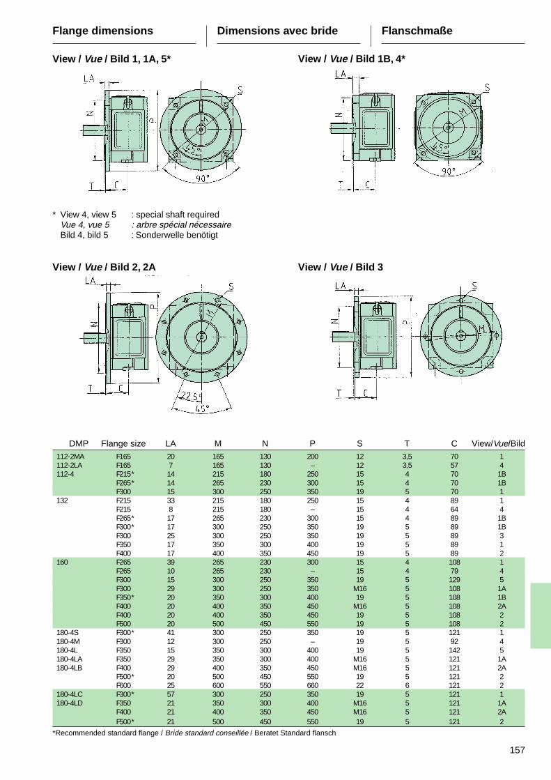
157
DMP Flange size LA M N P S T C View/Vue/Bild112-2MA F165 20 165 130 200 12 3,5 70 1112-2LA F165 7 165 130 – 12 3,5 57 4112-4 F215* 14 215 180 250 15 4 70 1B
F265* 14 265 230 300 15 4 70 1BF300 15 300 250 350 19 5 70 1
132 F215 33 215 180 250 15 4 89 1F215 8 215 180 – 15 4 64 4F265* 17 265 230 300 15 4 89 1BF300* 17 300 250 350 19 5 89 1BF300 25 300 250 350 19 5 89 3F350 17 350 300 400 19 5 89 1F400 17 400 350 450 19 5 89 2
160 F265 39 265 230 300 15 4 108 1F265 10 265 230 – 15 4 79 4F300 15 300 250 350 19 5 129 5F300 29 300 250 350 M16 5 108 1AF350* 20 350 300 400 19 5 108 1BF400 20 400 350 450 M16 5 108 2AF400 20 400 350 450 19 5 108 2F500 20 500 450 550 19 5 108 2
180-4S F300* 41 300 250 350 19 5 121 1180-4M F300 12 300 250 – 19 5 92 4180-4L F350 15 350 300 400 19 5 142 5180-4LA F350 29 350 300 400 M16 5 121 1A180-4LB F400 29 400 350 450 M16 5 121 2A
F500* 20 500 450 550 19 5 121 2F600 25 600 550 660 22 6 121 2
180-4LC F300* 57 300 250 350 19 5 121 1180-4LD F350 21 350 300 400 M16 5 121 1A
F400 21 400 350 450 M16 5 121 2AF500* 21 500 450 550 19 5 121 2
*Recommended standard flange / Bride standard conseillée / Beratet Standard flansch
Flange dimensions Dimensions avec bride Flanschmaße
View / Vue / Bild 1, 1A, 5* View / Vue / Bild 1B, 4*
View / Vue / Bild 2, 2A View / Vue / Bild 3
* View 4, view 5 : special shaft requiredVue 4, vue 5 : arbre spécial nécessaireBild 4, bild 5 : Sonderwelle benötigt
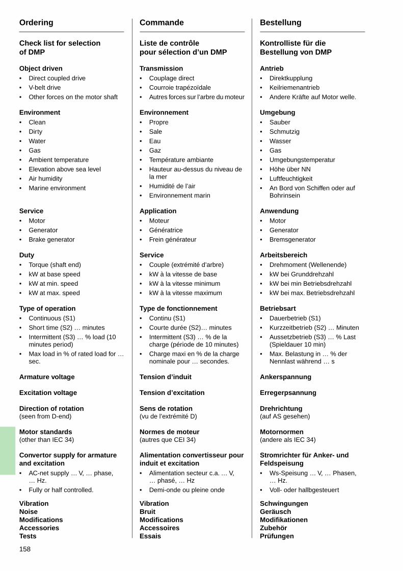
158
Ordering
Check list for selectionof DMP
Object driven• Direct coupled drive
• V-belt drive
• Other forces on the motor shaft
Environment• Clean
• Dirty
• Water
• Gas
• Ambient temperature
• Elevation above sea level
• Air humidity
• Marine environment
Service• Motor
• Generator
• Brake generator
Duty• Torque (shaft end)
• kW at base speed
• kW at min. speed
• kW at max. speed
Type of operation• Continuous (S1)
• Short time (S2) … minutes
• Intermittent (S3) … % load (10minutes period)
• Max load in % of rated load for …sec.
Armature voltage
Excitation voltage
Direction of rotation(seen from D-end)
Motor standards(other than IEC 34)
Convertor supply for armatureand excitation• AC-net supply … V, … phase,
… Hz.
• Fully or half controlled.
VibrationNoiseModificationsAccessoriesTests
Commande
Liste de contrôlepour sélection d’un DMP
Transmission• Couplage direct
• Courroie trapézoïdale
• Autres forces sur l’arbre du moteur
Environnement• Propre
• Sale
• Eau
• Gaz
• Température ambiante
• Hauteur au-dessus du niveau dela mer
• Humidité de l’air
• Environnement marin
Application• Moteur
• Génératrice
• Frein générateur
Service• Couple (extrémité d’arbre)
• kW à la vitesse de base
• kW à la vitesse minimum
• kW à la vitesse maximum
Type de fonctionnement• Continu (S1)
• Courte durée (S2)… minutes
• Intermittent (S3) … % de lacharge (période de 10 minutes)
• Charge maxi en % de la chargenominale pour … secondes.
Tension d’induit
Tension d’excitation
Sens de rotation(vu de l’extrémité D)
Normes de moteur(autres que CEI 34)
Alimentation convertisseur pourinduit et excitation• Alimentation secteur c.a. … V,
… phasé, … Hz
• Demi-onde ou pleine onde
VibrationBruitModificationsAccessoiresEssais
Bestellung
Kontrolliste für dieBestellung von DMP
Antrieb• Direktkupplung
• Keilriemenantrieb
• Andere Kräfte auf Motor welle.
Umgebung• Sauber
• Schmutzig
• Wasser
• Gas
• Umgebungstemperatur
• Höhe über NN
• Luftfeuchtigkeit
• An Bord von Schiffen oder aufBohrinsein
Anwendung• Motor
• Generator
• Bremsgenerator
Arbeitsbereich• Drehmoment (Wellenende)
• kW bei Grunddrehzahl
• kW bei min. Betriebsdrehzahl
• kW bei max. Betriebsdrehzahl
Betriebsart• Dauerbetrieb (S1)
• Kurzzeitbetrieb (S2) … Minuten
• Aussetzbetrieb (S3) … % Last(Spieldauer 10 min)
• Max. Belastung in … % derNennlast während … s
Ankerspannung
Erregerpsannung
Drehrichtung(auf AS gesehen)
Motornormen(andere als IEC 34)
Stromrichter für Anker- undFeldspeisung• Ws-Speisung … V, … Phasen,
… Hz.
• Voll- oder hallbgesteuert
SchwingungenGeräuschModifikationenZubehörPrüfungen
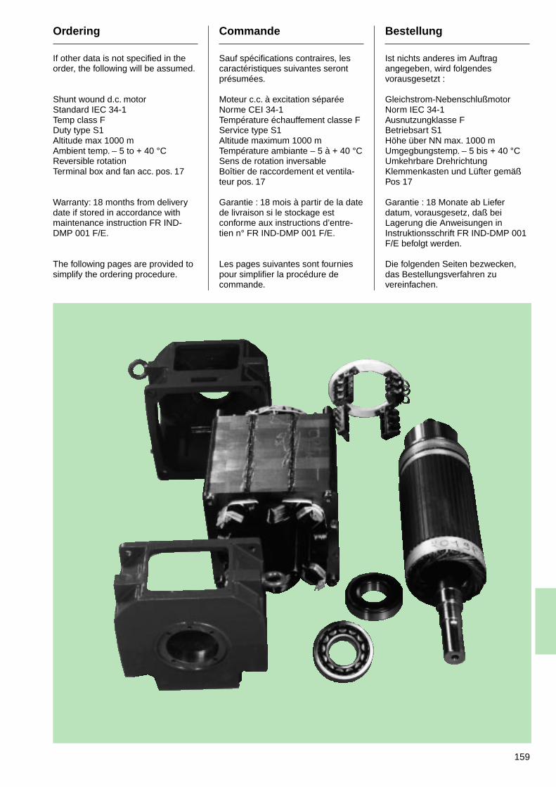
159
Ordering
If other data is not specified in theorder, the following will be assumed.
Shunt wound d.c. motorStandard IEC 34-1Temp class FDuty type S1Altitude max 1000 mAmbient temp. – 5 to + 40 °CReversible rotationTerminal box and fan acc. pos. 17
Warranty: 18 months from deliverydate if stored in accordance withmaintenance instruction FR IND-DMP 001 F/E.
The following pages are provided tosimplify the ordering procedure.
Commande
Sauf spécifications contraires, lescaractéristiques suivantes serontprésumées.
Moteur c.c. à excitation séparéeNorme CEI 34-1Température échauffement classe FService type S1Altitude maximum 1000 mTempérature ambiante – 5 à + 40 °CSens de rotation inversableBoîtier de raccordement et ventila-teur pos. 17
Garantie : 18 mois à partir de la datede livraison si le stockage estconforme aux instructions d’entre-tien n° FR IND-DMP 001 F/E.
Les pages suivantes sont fourniespour simplifier la procédure decommande.
Bestellung
Ist nichts anderes im Auftragangegeben, wird folgendesvorausgesetzt :
Gleichstrom-NebenschlußmotorNorm IEC 34-1Ausnutzungklasse FBetriebsart S1Höhe über NN max. 1000 mUmgegbungstemp. – 5 bis + 40 °CUmkehrbare DrehrichtungKlemmenkasten und Lüfter gemäßPos. 17
Garantie : 18 Monate ab Lieferdatum, vorausgesetz, daß beiLagerung die Anweisungen inInstruktionsschrift FR IND-DMP 001F/E befolgt werden.
Die folgenden Seiten bezwecken,das Bestellungsverfahren zuvereinfachen.
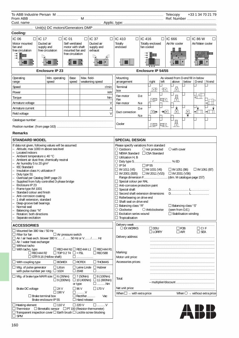
160
To ABB Industrie Persan M ................................................................................................................................................................................. Telecopy +33 1 34 70 21 79From ABB ................................................................................. M ................................................................................................................................... Ref. Number ................................................
Cust. name ..................................................................................................................... Applic. type: ........................................................................................................................................................
.................................. Unit(s) DC motors/Generators DMP ............................................................................................................................................................................................................
Cooling:
IC 06 IC 17 IC 01 IC 37 IC 410 IC 416 IC 666 IC 86 WMotor mounted Ducted air Self ventilated Ducted air Totally Totally enclosed Air/Air cooler Air/Water coolerfan and supply and motor with shaft supply and enclosed fan cooledfree circulation free circulation mounted fan and exhaust
free circulation
Enclosure IP 23 Enclosure IP 54/55
Operating Min. operating Base Max. field-range speed speed weakening speed
Speed r/min
Power kW
Torque Nm
Armature voltage V
Armature current A
Field voltage V
Catalogue number: ..............................................................................................................................
Position number: (from page 163) ..............................................................................................
Remarks
STANDARD MODELIf data not given, following values will be assumed:– Altitude, max 1000 m above sea level– Located indoors– Ambient temperature ≤ 40 °C– Ambient air dust-free, chemically neutral– Air humidity 5 to 20 g/m3
– IEC Standard– Insulation class H, utilization F– Duty type S1– Overload per Catalog DMP, page 23– Supplied from fully controlled 3-phase bridge– Enclosure IP 23– Frame type IM 1001– Standard colour and finish– Anti-corrosion coating– 1 shaft extension, standard– Deep-groove ball bearings– Normal seal– Balancing class “N”– Rotation: both directions– Separate excitation
Mounting As viewed from D-end fill in belowarrangement right left above below D-end N-end
Terminalbox
Fan motor D.eFanFan motor N.e
D.eDuct connection
N.e
Cooler
SPECIAL DESIGNPlease specify variations from standard
Outdoors not protected with coverNEMA Standard CSA StandardUtilization H, BDuty type S.............................. /.............................. % EDIP 54 IP 55IM 1011 (V5) IM 1031 (V6) IM 1051 (B6) IM 1061 (B7)IM 2001 (B35) IM 2011 (V15) IM 2031 (V36)Flange dimension F........................................ (dim. M catalogue page 157)Special colour per RALAnti-corrosive protection paintSpecial shaft D.............................. L..............................
Second shaft extension dimensions D.............................. L..............................
Rollerbearing on drive endShaft seal on drive endBalancing class “R” Balancing class “S”Clockwise Anticlockwise (seen from D.E.)Excitation series wound Stabilisation windingTropicalisation
ACCESSORIESMounted fan 380 Vac / 50 HzFilter for fan Air pressure switchAir / air heat exch. blower 380 V.......... /.......... 50 Hz or V.......... /.......... HzAir / water heat exchangerWithout tachoWith tacho, type REO 444 N1 REO 444 L1 REO 444 R1
REO 444 R2 TDP 0.2 T4 + FSL REO 588 GTR 9.16 (Hollow shaft) .............................
With coupling type BOWEX ROTEX THOMAS
Mtg. of pulse generator Litton Leine Linde Hubnerwith pulse number per rotg.: 1024 2048 .......................
Mtg. of brake type MAYR size: 6 (26Nm) 7 (50Nm) 8 (100Nm) 9 (200Nm) 10 (400Nm) 11 (800Nm)
or type: ...............NmBrake DC voltage 24 V 96 V 170 V
190 V ..............V Brake terminal box Rectifier.............. Vac Brake enclosure IP 55 Hand release
Heating element 110 V 220 V ..............V Thermistor Bimetallic sensor PT 100 (Resistor-thermometer) Transparent inspection cover Earth brush Loctite screw blockingSPM
Delivery week ..................................................................................................................................... EX WORKS DDU FOB C I F
LORRY AIR SEADelivery address: ...........................................................................................................
...........................................................................................................
...........................................................................................................
...........................................................................................................
Marking: ...........................................................................................................
Motor unit price: ...........................................................................................................
Accessories prices: ............................................................................................................................................................................................................................................................................................................................................................................................................................................
Total: ...........................................................................................................– multiplier/discount ................................................................
Net unit price: ...........................................................................................................
When → with extra price When → without extra price
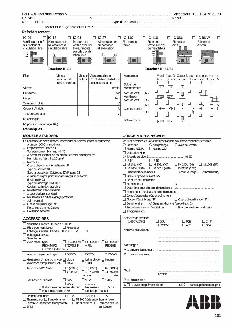
161
Pour ABB Industrie Persan M ............................................................................................................................................................................. Télécopieur +33 1 34 70 21 79De ABB ....................................................................................... M ................................................................................................................................... N° réf. .................................................................
Nom du client .............................................................................................................. Type d’application : ......................................................................................................................................
.................................. Moteurs c.c./générateurs DMP .........................................................................................................................................................................................................................
Refroidissement :
IC 06 IC 17 IC 01 IC 37 IC 410 IC 416 IC 666 IC 86 WVentilateur monté Alimentation en Moteur auto- Alimentation en Entièrement Entièrement Echangeur Echangeursur moteur et air canalisée et ventilé avec ven- air canalisée fermé fermé, refroidi air/air air/eaucirculation libre circulation libre tilateur monté et évacuation par ventilateur
sur arbre et cir-lation libre
Enceinte IP 23 Enceinte IP 54/55
Plage Vitesse Vitesse Vitesse maximumminimum de de base d’exploitation d’affaiblis-fonctionnement sement du champ
Vitesse tr/min
Puissance kW
Couple Nm
Tension d’induit V
Courant d’induit A
Tension de champ V
N° catalogue : ........................................................................................................................................
N° position : (voir page 163) ..........................................................................................................
Remarques
MODÈLE STANDARDEn l’absence de spécification, les valeurs suivantes seront présumées :– Altitude : 1000 m maximum– Emplacement : intérieur– Température ambiante ≤ 40 °C– Air ambiant exempt de poussière, chimiquement neutre– Humidité de l’air : 5 à 20 g/m3
– Norme CEI– Classe d’isolement H, utilisation F– Type de service S1– Surcharge suivant Catalogue DMP, page 23– Alimentation par pont triphasé à régulation totale– Enceinte IP 23– Type de montage : IM 1001– Couleur et finition standard– Revêtement anti-corrosion– 1 bout d’arbre, standard– Roulements à billes à gorge profonde– Joint normal– Classe d’équilibrage “N”– Rotation : dans les 2 sens– Excitation séparée
Agencement Vue de l’extr. D - Cocher la case corresp. de montagedroite gauche dessus dessous extr. D extr. N
Boîtier deraccordement
Mot. de vent. ASVentilateurMot. de vent BS
ASDuct connection
BS
Refroidisseur
CONCEPTION SPÉCIALEVeuillez préciser les variations par rapport aux caractéristiques standard
Extérieur non protégé avec couvercleNorme NEMA Norme CSAUtilisation H, BType de service S.............................. /.............................. % EDIP 54 IP 55IM 1011 (V5) IM 1031 (V6) IM 1051 (B6) IM 1061 (B7)IM 2001 (B35) IM 2011 (V15) IM 2031 (V36)Dimension de la bride F........................................ (cote M, page 157 du catalogue)Couleur spécial suivant RALPeinture anti-corrosionArbre spécial D.............................. L..............................
Deuxième bout d’arbre, dimensions : D.............................. L..............................
Roulement à rouleaux côté entraînementJoint d’étanchéité côté entraînementClasse d’équilibrage “R” Classe d’équilibrage “S”Sens horaire Sens anti-horaire (vu de l’ext. D)Enroulement série d’excitation Enroulement de stabilisationTropicalisation
ACCESSOIRESVentilateur monté 380 V c.a./ 50 HzFiltre pour ventilateur PressostatEchangeur air/air 380 V/50 Hz ou .......... V/.......... HzEchangeur air/eauSans tachoAvec tacho, type REO 444 N1 REO 444 L1 REO 444 R1
REO 444 R2 TDP 0.2 T4 + FSL REO 588 GTR 9.16 (arbre creux) .............................
Avec accouplement type BOWEX ROTEX THOMAS
Générateur d’impulsions type Litton Leine Linde Hubneravec nbre d’impulsions/rot. 1024 2048 .......................
Frein type MAYR taille : 6 (26Nm) 7 (50Nm) 8 (100Nm) 9 (200Nm) 10 (400Nm) 11 (800Nm)
ou type: ...............NmTension c.c. du frein 24 V 96 V 170 V
190 V ..............V Boîtier de raccordement de frein Redresseur.............. V c.a. Enceinte de frein IP 55 Déblocage manuel
Elément chauffant 110 V 220 V ..............V Thermistance Sonde bilame PT 100 (résistance-thermomètre) Fenêtre d’inspection transparente Balai de terre Freinage des vis SPM par Loctite
Semaine de livraison ......................................................................................................................
EX WORKS DDU FOB C I F LORRY AIR SEA
Adresse de livraison : ............................................................................................................................................................................................................................................................................................................................................................................................................................................
Marquage : ...........................................................................................................
Prix unitaire du moteur : ...........................................................................................................
Prix des accessoires : ............................................................................................................................................................................................................................................................................................................................................................................................................................................
Total : ...........................................................................................................– remise .........................................................................................
Prix unitaire net : ...........................................................................................................
Si → avec supplément de prix Si → sans supplément de prix
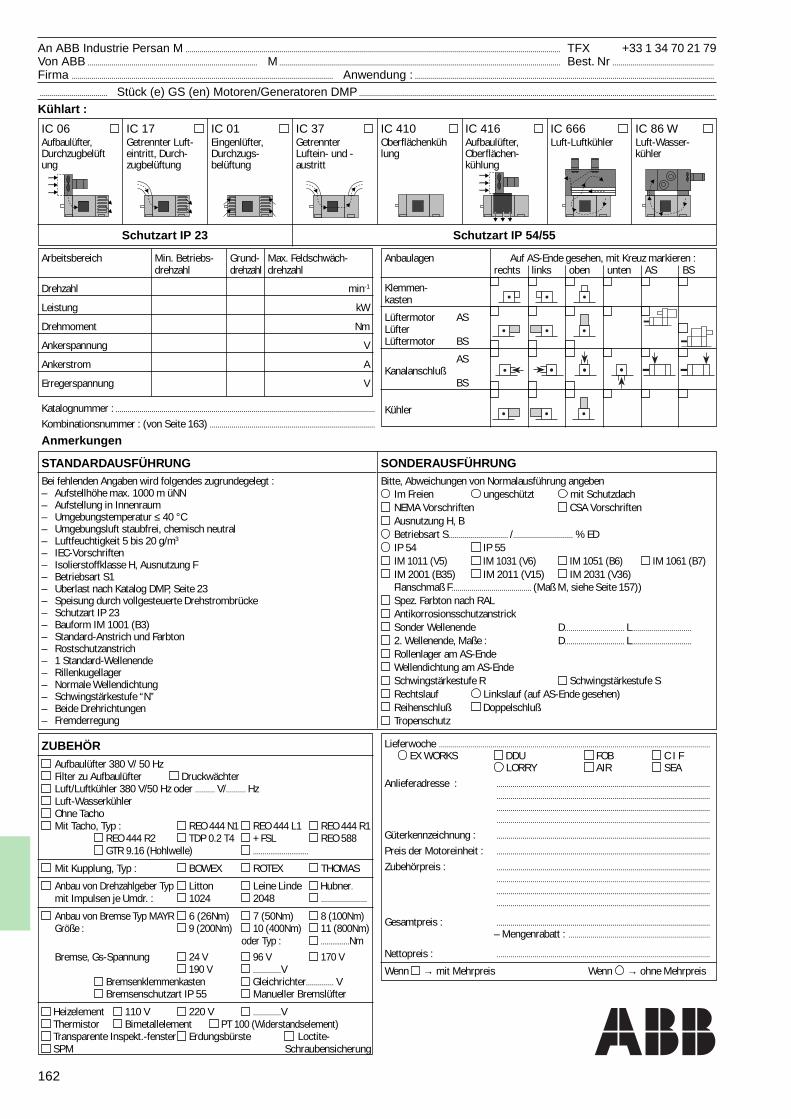
162
An ABB Industrie Persan M ............................................................................................................................................................................................ TFX +33 1 34 70 21 79Von ABB ..................................................................................... M ............................................................................................................................................. Best. Nr ...................................................
Firma ................................................................................................................................... Anwendung : ......................................................................................................................................................
.................................. Stück (e) GS (en) Motoren/Generatoren DMP ..................................................................................................................................................................................
Kühlart :
IC 06 IC 17 IC 01 IC 37 IC 410 IC 416 IC 666 IC 86 WAufbaulüfter, Getrennter Luft- Eingenlüfter, Getrennter Oberflächenküh Aufbaulüfter, Luft-Luftkühler Luft-Wasser-Durchzugbelüft eintritt, Durch- Durchzugs- Luftein- und - lung Oberflächen- kühlerung zugbelüftung belüftung austritt kühlung
-
Schutzart IP 23 Schutzart IP 54/55
Arbeitsbereich Min. Betriebs- Grund- Max. Feldschwäch-drehzahl drehzahl drehzahl
Drehzahl min-1
Leistung kW
Drehmoment Nm
Ankerspannung V
Ankerstrom A
Erregerspannung V
Katalognummer : ..................................................................................................................................
Kombinationsnummer : (von Seite 163) ...................................................................................
Anmerkungen
STANDARDAUSFÜHRUNGBei fehlenden Angaben wird folgendes zugrundegelegt :– Aufstellhöhe max. 1000 m üNN– Aufstellung in Innenraum– Umgebungstemperatur ≤ 40 °C– Umgebungsluft staubfrei, chemisch neutral– Luftfeuchtigkeit 5 bis 20 g/m3
– IEC-Vorschriften– Isolierstoffklasse H, Ausnutzung F– Betriebsart S1– Uberlast nach Katalog DMP, Seite 23– Speisung durch vollgesteuerte Drehstrombrücke– Schutzart IP 23– Bauform IM 1001 (B3)– Standard-Anstrich und Farbton– Rostschutzanstrich– 1 Standard-Wellenende– Rillenkugellager– Normale Wellendichtung– Schwingstärkestufe “N”– Beide Drehrichtungen– Fremderregung
Anbaulagen Auf AS-Ende gesehen, mit Kreuz markieren :rechts links oben unten AS BS
Klemmen-kasten
Lüftermotor ASLüfterLüftermotor BS
ASKanalanschluß
BS
Kühler
SONDERAUSFÜHRUNGBitte, Abweichungen von Normalausführung angeben
Im Freien ungeschützt mit SchutzdachNEMA Vorschriften CSA VorschriftenAusnutzung H, BBetriebsart S.............................. /.............................. % EDIP 54 IP 55IM 1011 (V5) IM 1031 (V6) IM 1051 (B6) IM 1061 (B7)IM 2001 (B35) IM 2011 (V15) IM 2031 (V36)Flanschmaß F........................................ (Maß M, siehe Seite 157))Spez. Farbton nach RALAntikorrosionsschutzanstrickSonder Wellenende D.............................. L..............................
2. Wellenende, Maße : D.............................. L..............................
Rollenlager am AS-EndeWellendichtung am AS-EndeSchwingstärkestufe R Schwingstärkestufe SRechtslauf Linkslauf (auf AS-Ende gesehen)Reihenschluß DoppelschlußTropenschutz
ZUBEHÖRAufbaulüfter 380 V/ 50 HzFilter zu Aufbaulüfter DruckwächterLuft/Luftkühler 380 V/50 Hz oder .......... V/.......... HzLuft-WasserkühlerOhne TachoMit Tacho, Typ : REO 444 N1 REO 444 L1 REO 444 R1
REO 444 R2 TDP 0.2 T4 + FSL REO 588 GTR 9.16 (Hohlwelle) .............................
Mit Kupplung, Typ : BOWEX ROTEX THOMAS
Anbau von Drehzahlgeber Typ Litton Leine Linde Hubner.
mit Impulsen je Umdr. : 1024 2048 .......................
Anbau von Bremse Typ MAYR 6 (26Nm) 7 (50Nm) 8 (100Nm)Größe : 9 (200Nm) 10 (400Nm) 11 (800Nm)
oder Typ : ...............NmBremse, Gs-Spannung 24 V 96 V 170 V
190 V ..............V Bremsenklemmenkasten Gleichrichter.............. V Bremsenschutzart IP 55 Manueller Bremslüfter
Heizelement 110 V 220 V ..............V Thermistor Bimetallelement PT 100 (Widerstandselement) Transparente Inspekt.-fenster Erdungsbürste Loctite- SPM Schraubensicherung
Lieferwoche ........................................................................................................................................ EX WORKS DDU FOB C I F
LORRY AIR SEAAnlieferadresse : ...........................................................................................................
...........................................................................................................
...........................................................................................................
...........................................................................................................
Güterkennzeichnung : ...........................................................................................................
Preis der Motoreinheit : ...........................................................................................................
Zubehörpreis : ............................................................................................................................................................................................................................................................................................................................................................................................................................................
Gesamtpreis : ...........................................................................................................– Mengenrabatt : .......................................................................
Nettopreis : ...........................................................................................................
Wenn → mit Mehrpreis Wenn → ohne Mehrpreis
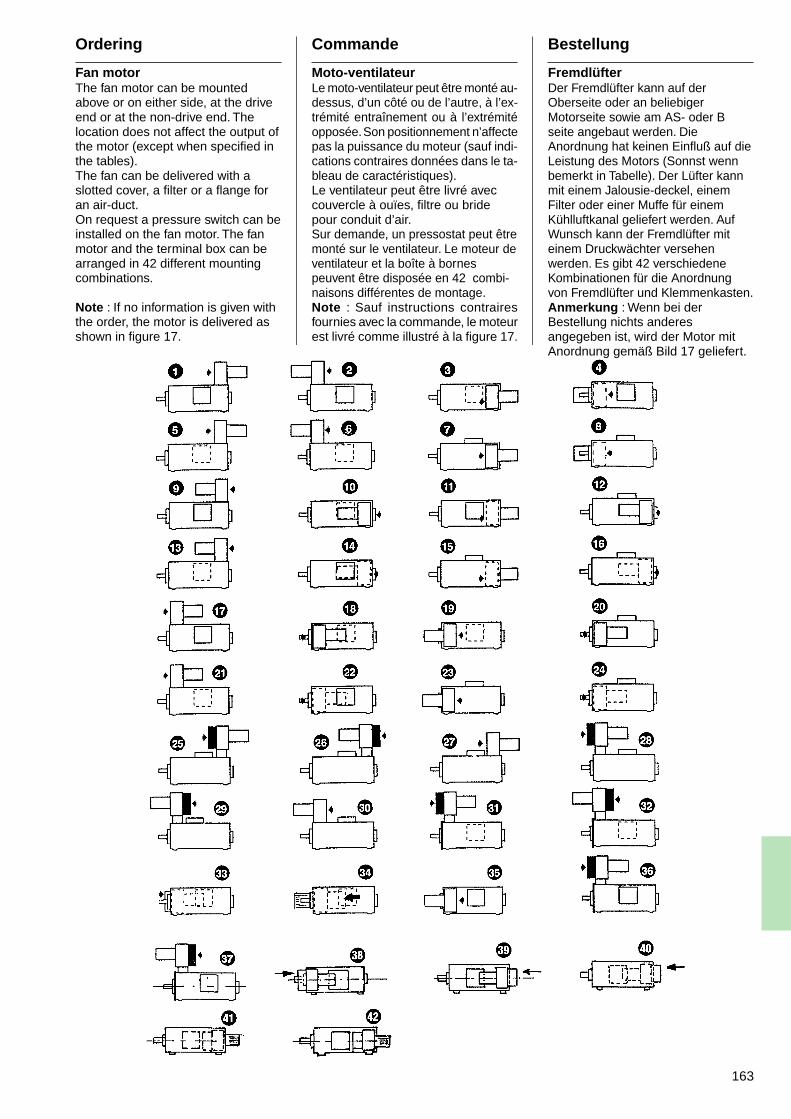
163
Ordering
Fan motorThe fan motor can be mountedabove or on either side, at the driveend or at the non-drive end. Thelocation does not affect the output ofthe motor (except when specified inthe tables).The fan can be delivered with aslotted cover, a filter or a flange foran air-duct.On request a pressure switch can beinstalled on the fan motor. The fanmotor and the terminal box can bearranged in 42 different mountingcombinations.
Note : If no information is given withthe order, the motor is delivered asshown in figure 17.
Commande
Moto-ventilateurLe moto-ventilateur peut être monté au-dessus, d’un côté ou de l’autre, à l’ex-trémité entraînement ou à l’extrémitéopposée. Son positionnement n’affectepas la puissance du moteur (sauf indi-cations contraires données dans le ta-bleau de caractéristiques).Le ventilateur peut être livré aveccouvercle à ouïes, filtre ou bridepour conduit d’air.Sur demande, un pressostat peut êtremonté sur le ventilateur. Le moteur deventilateur et la boîte à bornespeuvent être disposée en 42 combi-naisons différentes de montage.Note : Sauf instructions contrairesfournies avec la commande, le moteurest livré comme illustré à la figure 17.
Bestellung
FremdlüfterDer Fremdlüfter kann auf derOberseite oder an beliebigerMotorseite sowie am AS- oder Bseite angebaut werden. DieAnordnung hat keinen Einfluß auf dieLeistung des Motors (Sonnst wennbemerkt in Tabelle). Der Lüfter kannmit einem Jalousie-deckel, einemFilter oder einer Muffe für einemKühlluftkanal geliefert werden. AufWunsch kann der Fremdlüfter miteinem Druckwächter versehenwerden. Es gibt 42 verschiedeneKombinationen für die Anordnungvon Fremdlüfter und Klemmenkasten.Anmerkung : Wenn bei derBestellung nichts anderesangegeben ist, wird der Motor mitAnordnung gemäß Bild 17 geliefert.

164
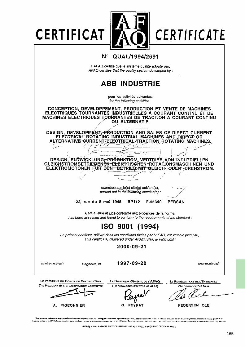
165

166
167

168
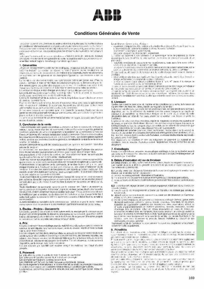
169
Conditions Générales de Vente
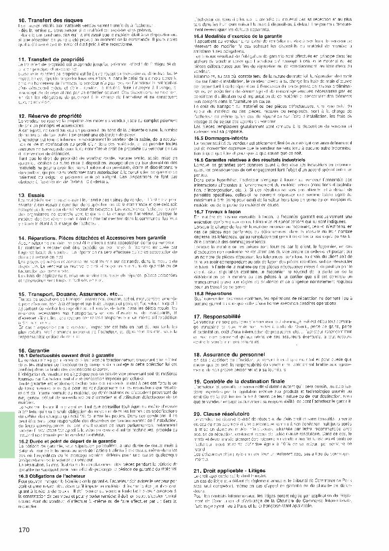
170
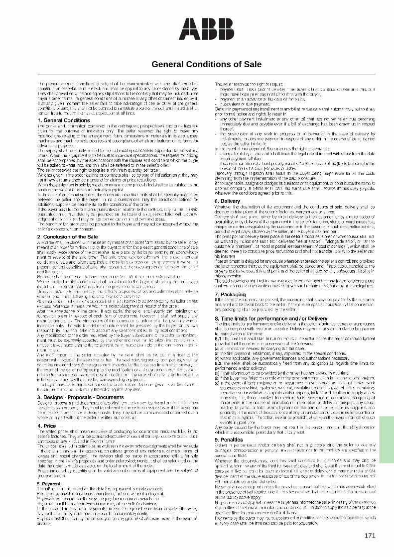
171
General Conditions of Sale
172

ABB Industrie22, rue du 8 mai 1945BP 112F-95340 PersanTél : +33 (0)1 30 28 60 00Fax : +33 (0)1 34 70 21 79 FR
IND
- C
at D
MP
F/D
/E -
02/
98 -
Prin
ted
in C
EE
- S
IFC
-Mic
Ed
it : +
33 (
0)4
78 2
7 74
92


![[Youdz.ru] тепловые двигатели](https://img.pdfslide.tips/doc/110x75/54522621af7959ed518b9107/youdzru--5584b59c3424c.jpg)