Embed Size (px)
Citation preview

888-867-2360 www.tmpservices.com
Installation Manual
Aluminum
Proudly Made in the USA
Installation Guide
2
Tools Required: � Generator (or power from building)
� ” Drill (heavy duty)
� Non-Ferrous Saw
� Grinder
� Dry Wall Screw Gun for Self Tapping Screws
� Combination Wrench and Socket Set 9/16”
� 4’ or 6’ Level (preferably smart level)
� C-Clamp (preferably locking type)
� 3/8” and 5/16” Magnet Drive Hex Bit Attachment
� 7/16” Drill Bit
� Measuring Tape
� String Line (if using optional offset)
View Packing List:
Each ramp system is shipped with a packing list, TMP layout of the site design,
and sales order. Be sure to check that all items are on hand prior to beginning the
installation.
Table of Contents
� Getting Started Page 4-5
3
� Installing First Landing Section Page 6-9 � Installing First Ramp Section Page 10 � Installing Toe Section Page 11
� Installing Guardrails Page 12
� Drilling Guardrails Page 13 � Installing Angle Bracing Page 14-15 � Touch Up and Completion Page 16 � Options Page 18-22
Getting Started
A. Unpack ramp. All handrails and hardware are packaged in between ramp and landing
sections.
4
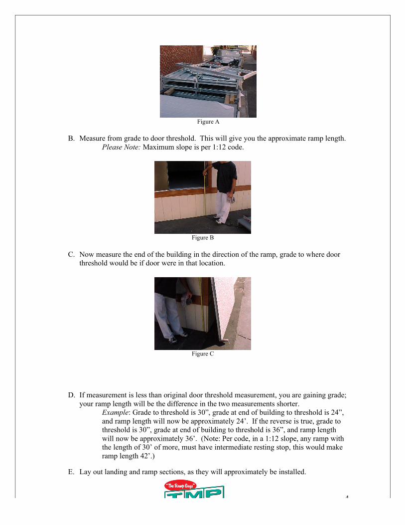
Figure A
B. Measure from grade to door threshold. This will give you the approximate ramp length.
Please Note: Maximum slope is per 1:12 code.
Figure B
C. Now measure the end of the building in the direction of the ramp, grade to where door
threshold would be if door were in that location.
Figure C
D. If measurement is less than original door threshold measurement, you are gaining grade;
your ramp length will be the difference in the two measurements shorter.
Example: Grade to threshold is 30”, grade at end of building to threshold is 24”,
and ramp length will now be approximately 24’. If the reverse is true, grade to
threshold is 30”, grade at end of building to threshold is 36”, and ramp length
will now be approximately 36’. (Note: Per code, in a 1:12 slope, any ramp with
the length of 30’ of more, must have intermediate resting stop, this would make
ramp length 42’.)
E. Lay out landing and ramp sections, as they will approximately be installed.
5
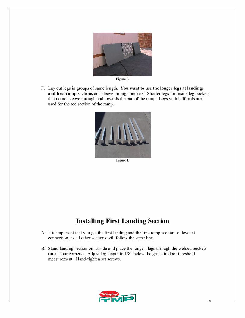
Figure D
F. Lay out legs in groups of same length. You want to use the longer legs at landings
and first ramp sections and sleeve through pockets. Shorter legs for inside leg pockets
that do not sleeve through and towards the end of the ramp. Legs with half pads are
used for the toe section of the ramp.
Figure E
Installing First Landing Section
A. It is important that you get the first landing and the first ramp section set level at
connection, as all other sections will follow the same line.
B. Stand landing section on its side and place the longest legs through the welded pockets
(in all four corners). Adjust leg length to 1/8” below the grade to door threshold
measurement. Hand-tighten set screws.
6
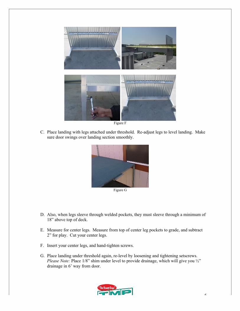
Figure F
C. Place landing with legs attached under threshold. Re-adjust legs to level landing. Make
sure door swings over landing section smoothly.
Figure G
D. Also, when legs sleeve through welded pockets, they must sleeve through a minimum of
18” above top of deck.
E. Measure for center legs. Measure from top of center leg pockets to grade, and subtract
2” for play. Cut your center legs.
F. Insert your center legs, and hand-tighten screws.
G. Place landing under threshold again, re-level by loosening and tightening setscrews.
Please Note: Place 1/8” shim under level to provide drainage, which will give you ”
drainage in 6’ way from door.
7
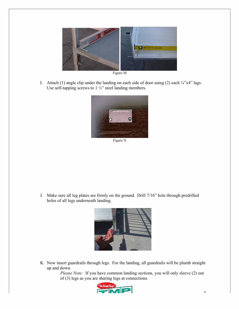
Figure M
I. Attach (1) angle clip under the landing on each side of door using (2) each ”x4” lags.
Use self-tapping screws to 1 ” steel landing members.
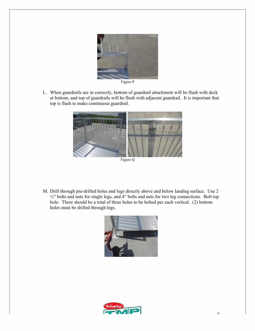
Figure N
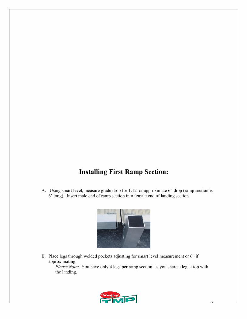
J. Make sure all leg plates are firmly on the ground. Drill 7/16” hole through predrilled
holes of all legs underneath landing.
K. Now insert guardrails through legs. For the landing, all guardrails will be plumb straight
up and down.
Please Note: If you have common landing sections, you will only sleeve (2) out
of (3) legs as you are sharing legs at connections.
8
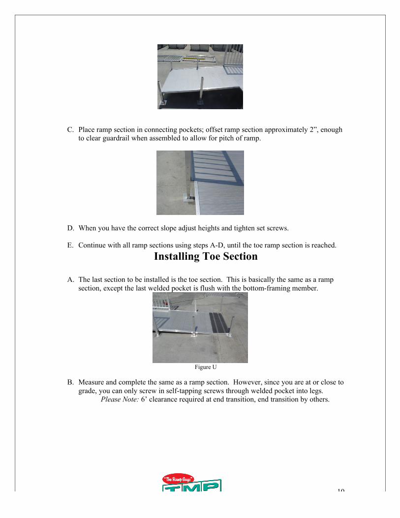
Figure P
L. When guardrails are in correctly, bottom of guardrail attachment will be flush with deck
at bottom, and top of guardrails will be flush with adjacent guardrail. It is important that
top is flush to make continuous guardrail.
Figure Q
M. Drill through pre-drilled holes and legs directly above and below landing surface. Use 2
” bolts and nuts for single legs, and 4” bolts and nuts for two leg connections. Bolt top
hole. There should be a total of three holes to be bolted per each vertical. (2) bottom
holes must be drilled through legs.
9
Installing First Ramp Section:
A. Using smart level, measure grade drop for 1:12, or approximate 6” drop (ramp section is
6’ long). Insert male end of ramp section into female end of landing section.
B. Place legs through welded pockets adjusting for smart level measurement or 6” if
approximating.
Please Note: You have only 4 legs per ramp section, as you share a leg at top with
the landing.
10
C. Place ramp section in connecting pockets; offset ramp section approximately 2”, enough
to clear guardrail when assembled to allow for pitch of ramp.
D. When you have the correct slope adjust heights and tighten set screws.
E. Continue with all ramp sections using steps A-D, until the toe ramp section is reached.
Installing Toe Section
A. The last section to be installed is the toe section. This is basically the same as a ramp
section, except the last welded pocket is flush with the bottom-framing member.
Figure U
B. Measure and complete the same as a ramp section. However, since you are at or close to
grade, you can only screw in self-tapping screws through welded pocket into legs.
Please Note: 6’ clearance required at end transition, end transition by others.
11
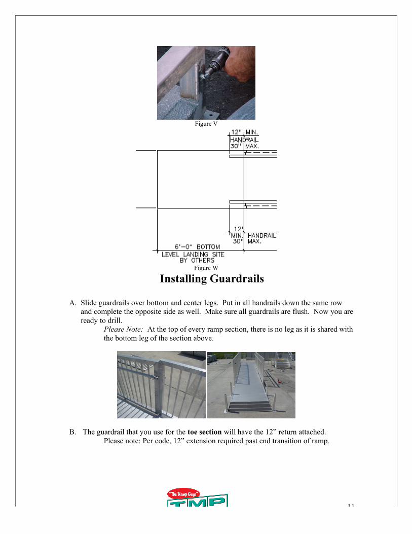
Figure V
Figure W
Installing Guardrails
A. Slide guardrails over bottom and center legs. Put in all handrails down the same row
and complete the opposite side as well. Make sure all guardrails are flush. Now you are
ready to drill.
Please Note: At the top of every ramp section, there is no leg as it is shared with
the bottom leg of the section above.
B. The guardrail that you use for the toe section will have the 12” return attached.
Please note: Per code, 12” extension required past end transition of ramp.
12
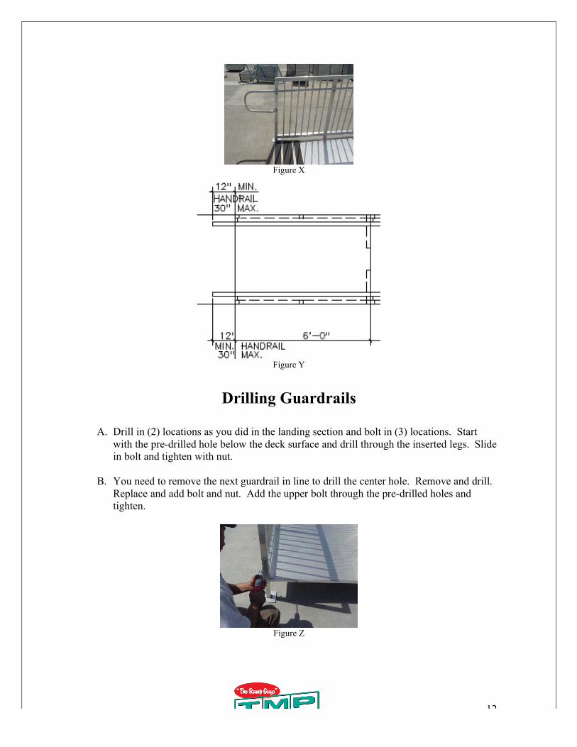
Figure X
Figure Y
Drilling Guardrails
A. Drill in (2) locations as you did in the landing section and bolt in (3) locations. Start
with the pre-drilled hole below the deck surface and drill through the inserted legs. Slide
in bolt and tighten with nut.
B. You need to remove the next guardrail in line to drill the center hole. Remove and drill.
Replace and add bolt and nut. Add the upper bolt through the pre-drilled holes and
tighten.
Figure Z
13
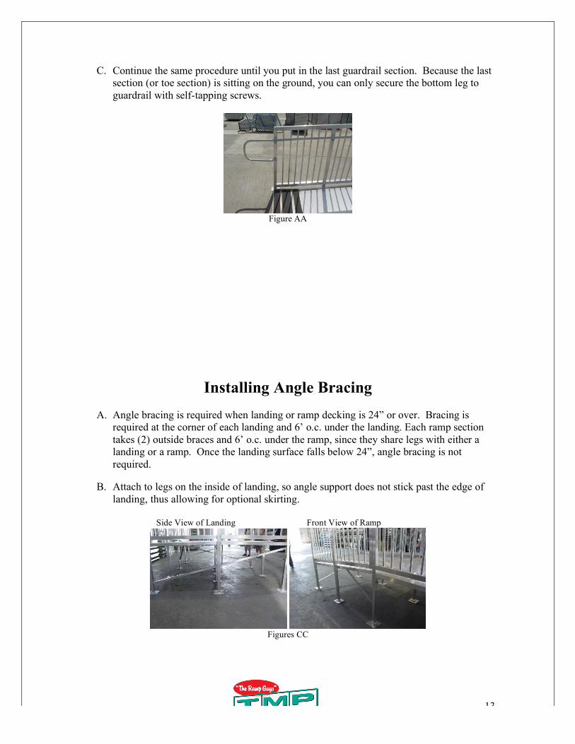
C. Continue the same procedure until you put in the last guardrail section. Because the last
section (or toe section) is sitting on the ground, you can only secure the bottom leg to
guardrail with self-tapping screws.
Figure AA
Installing Angle Bracing
A. Angle bracing is required when landing or ramp decking is 24” or over. Bracing is
required at the corner of each landing and 6’ o.c. under the landing. Each ramp section
takes (2) outside braces and 6’ o.c. under the ramp, since they share legs with either a
landing or a ramp. Once the landing surface falls below 24”, angle bracing is not
required.
B. Attach to legs on the inside of landing, so angle support does not stick past the edge of
landing, thus allowing for optional skirting.
Side View of Landing Front View of Ramp
Figures CC
14
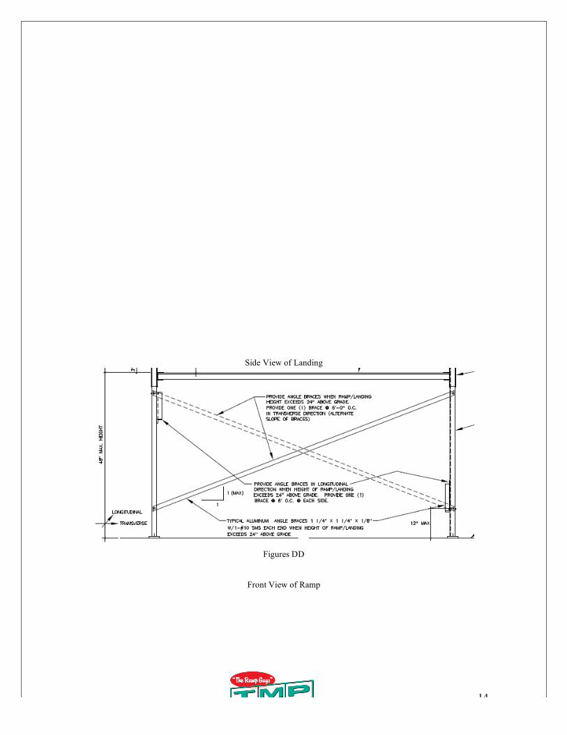
Side View of Landing
Figures DD
Front View of Ramp
15
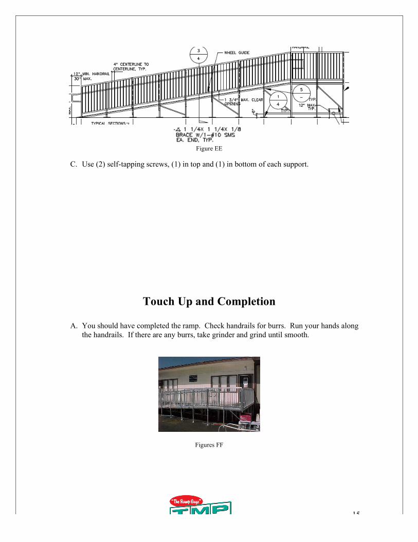
Figure EE
C. Use (2) self-tapping screws, (1) in top and (1) in bottom of each support.
Touch Up and Completion
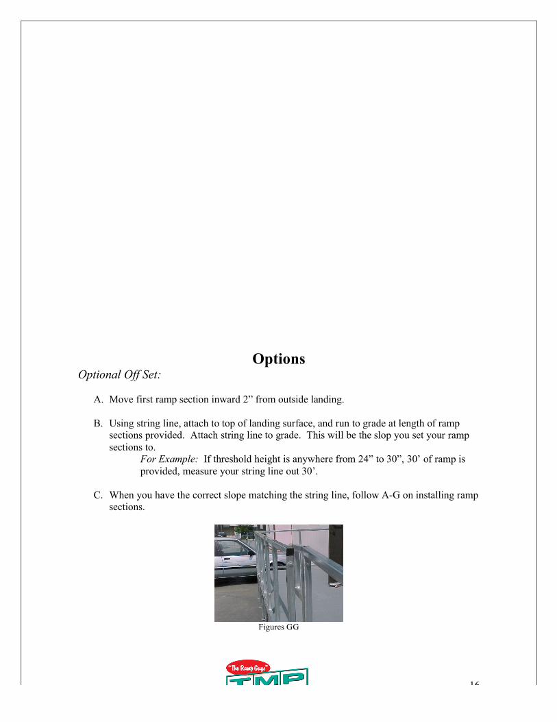
A. You should have completed the ramp. Check handrails for burrs. Run your hands along
the handrails. If there are any burrs, take grinder and grind until smooth.
Figures FF
16
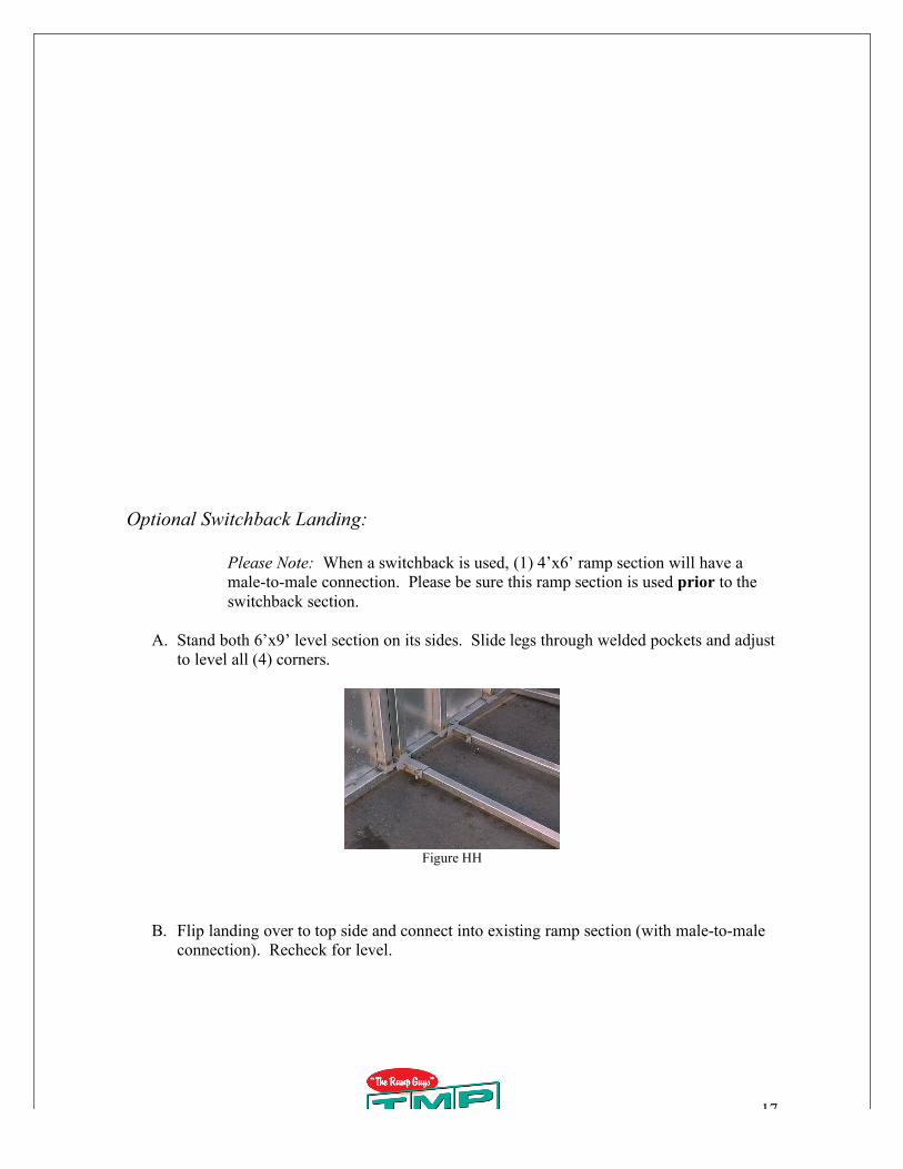
Options Optional Off Set:
A. Move first ramp section inward 2” from outside landing.
B. Using string line, attach to top of landing surface, and run to grade at length of ramp
sections provided. Attach string line to grade. This will be the slop you set your ramp
sections to.
For Example: If threshold height is anywhere from 24” to 30”, 30’ of ramp is
provided, measure your string line out 30’.
C. When you have the correct slope matching the string line, follow A-G on installing ramp
sections.
Figures GG
17
Optional Switchback Landing:
Please Note: When a switchback is used, (1) 4’x6’ ramp section will have a
male-to-male connection. Please be sure this ramp section is used prior to the
switchback section.
A. Stand both 6’x9’ level section on its sides. Slide legs through welded pockets and adjust
to level all (4) corners.
Figure HH
B. Flip landing over to top side and connect into existing ramp section (with male-to-male
connection). Recheck for level.
18
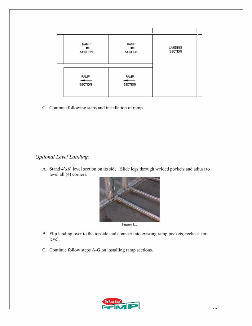
C. Continue following steps and installation of ramp.
Optional Level Landing:
A. Stand 4’x6’ level section on its side. Slide legs through welded pockets and adjust to
level all (4) corners.
Figure LL
B. Flip landing over to the topside and connect into existing ramp pockets, recheck for
level.
C. Continue follow steps A-G on installing ramp sections.
19
Figure MM
Optional Step Attachment:
A. Install landing per instructions on Installing First Landing Section.
B. Measure outside edge of landing from finished floor to top surface of landing, this will
determine your measurement of your step height.
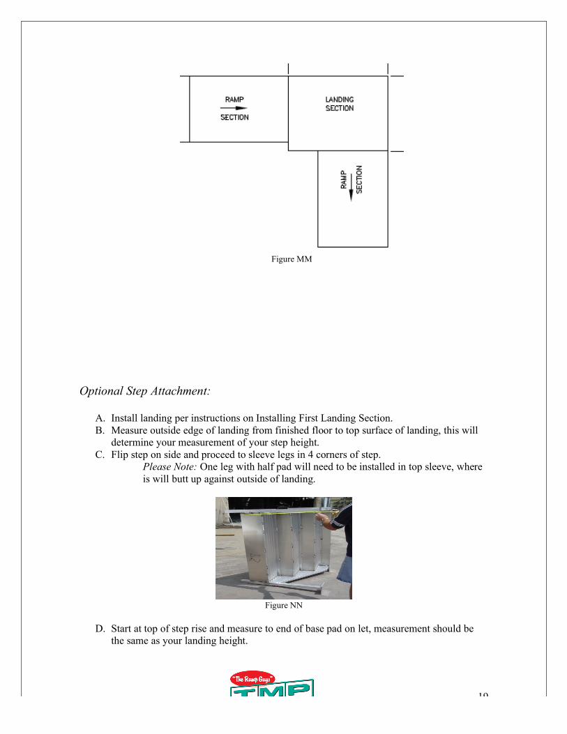
C. Flip step on side and proceed to sleeve legs in 4 corners of step.
Please Note: One leg with half pad will need to be installed in top sleeve, where
is will butt up against outside of landing.
Figure NN
D. Start at top of step rise and measure to end of base pad on let, measurement should be
the same as your landing height.
20
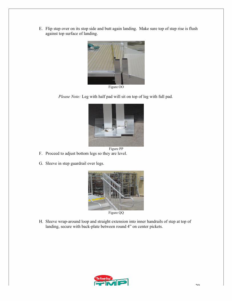
E. Flip step over on its stop side and butt again landing. Make sure top of step rise is flush
against top surface of landing.
Figure OO
Please Note: Leg with half pad will sit on top of leg with full pad.
Figure PP
F. Proceed to adjust bottom legs so they are level.
G. Sleeve in step guardrail over legs.
Figure QQ
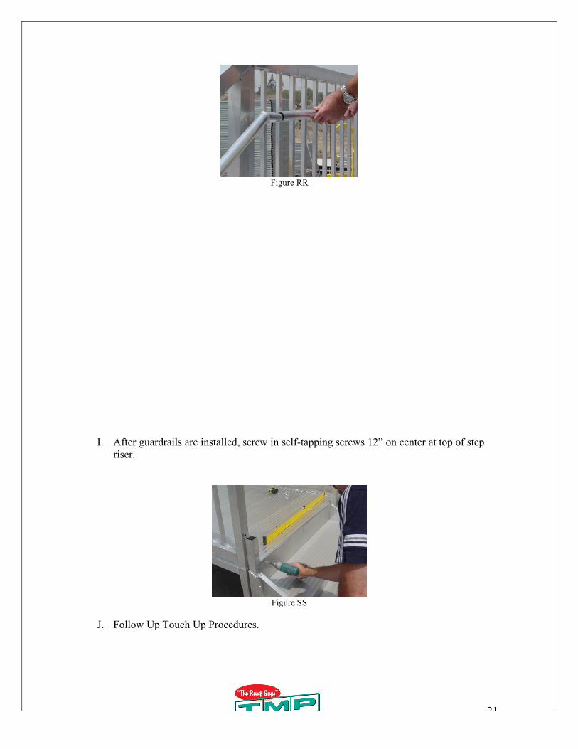
H. Sleeve wrap-around loop and straight extension into inner handrails of step at top of
landing, secure with back-plate between round 4” on center pickets.
21
Figure RR
I. After guardrails are installed, screw in self-tapping screws 12” on center at top of step
riser.
Figure SS
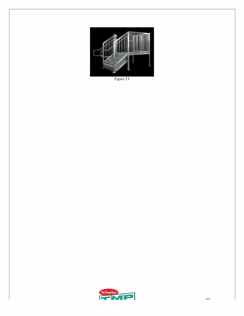
J. Follow Up Touch Up Procedures.
22
Figure TT


![LDT Installation Manual[1]](https://img.pdfslide.tips/doc/110x75/5571ff8d49795991699d87b6/ldt-installation-manual1.jpg)