Embed Size (px)
Citation preview
NON-DESTRUCTIVE BLAST FURNACE WALL TESTING
by Michael J. Vermeer
Dr. Yulian Kin, Advisor
Eric S. Roades Krasimir Zahariev
Bernard W. Parsons II
Friday, December 8, 2006
Background
• Blast Furnace is a tall vertical shaft used for refining iron ore into molten iron – Refractory brick forms the interior lining which comes into contact
with the iron and other refining materials • As iron is refined in the blast furnace, erosion occurs on this
refractory lining • Improved technology to monitor the erosion in this lining
will significantly increase profitability and productivity of blast furnace operation
• A project to develop this technology is made possible especially by the 21st Century Science and Technology Fund of Indiana
Project Purpose and Description
• The focus of this project is to investigate the use of acoustic measurement techniques to measure the thickness changes in a blast furnace wall.
• This was done through several phases of studies performed to validate different aspects to the acoustic method – In the first part of the project, it was verified that the concept
worked to determine depth in a regular, undamaged brick – Next it was used to detect shifting depths, as damage was
applied to a brick in laboratory conditions – A study was also performed to investigate the effect of the steel
lining on the outside of the furnace – Finally, the method was applied to an actual blast furnace to
monitor the wall thickness over time
Project Timeline
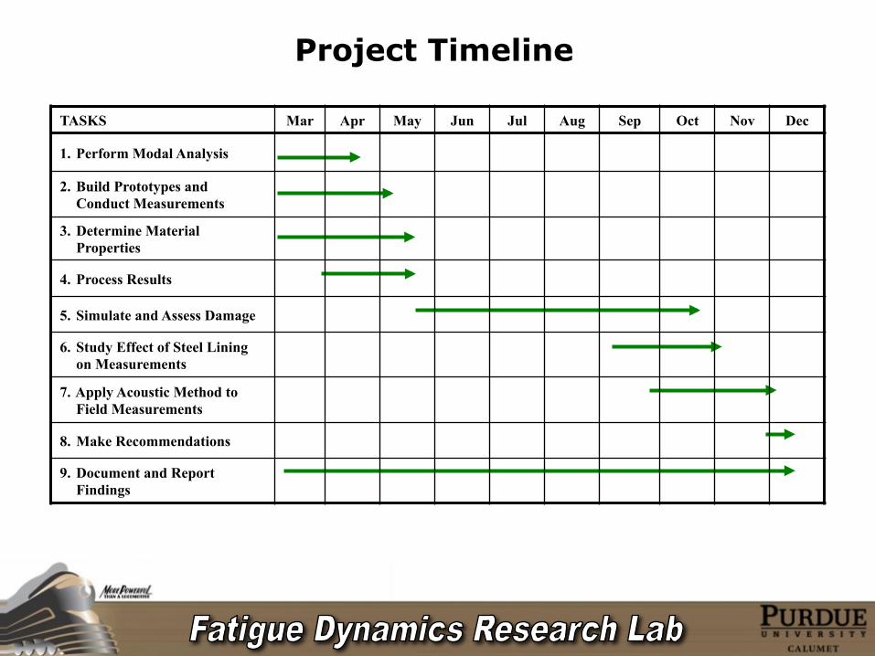
TASKS Mar Apr May Jun Jul Aug Sep Oct Nov Dec 1. Perform Modal Analysis 2. Build Prototypes and
Conduct Measurements 3. Determine Material
Properties 4. Process Results 5. Simulate and Assess Damage 6. Study Effect of Steel Lining
on Measurements 7. Apply Acoustic Method to
Field Measurements 8. Make Recommendations 9. Document and Report
Findings
Derivation of Formula
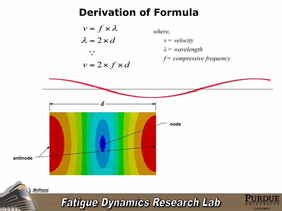
where, v = velocity λ = wavelength f = compressive frequency
node
antinode
dfv
dfv
××=
×=
×=
2
2
λλ
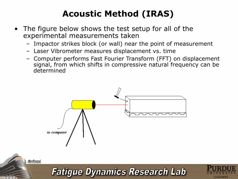
Acoustic Method (IRAS)
• The figure below shows the test setup for all of the experimental measurements taken – Impactor strikes block (or wall) near the point of measurement – Laser Vibrometer measures displacement vs. time – Computer performs Fast Fourier Transform (FFT) on displacement
signal, from which shifts in compressive natural frequency can be determined
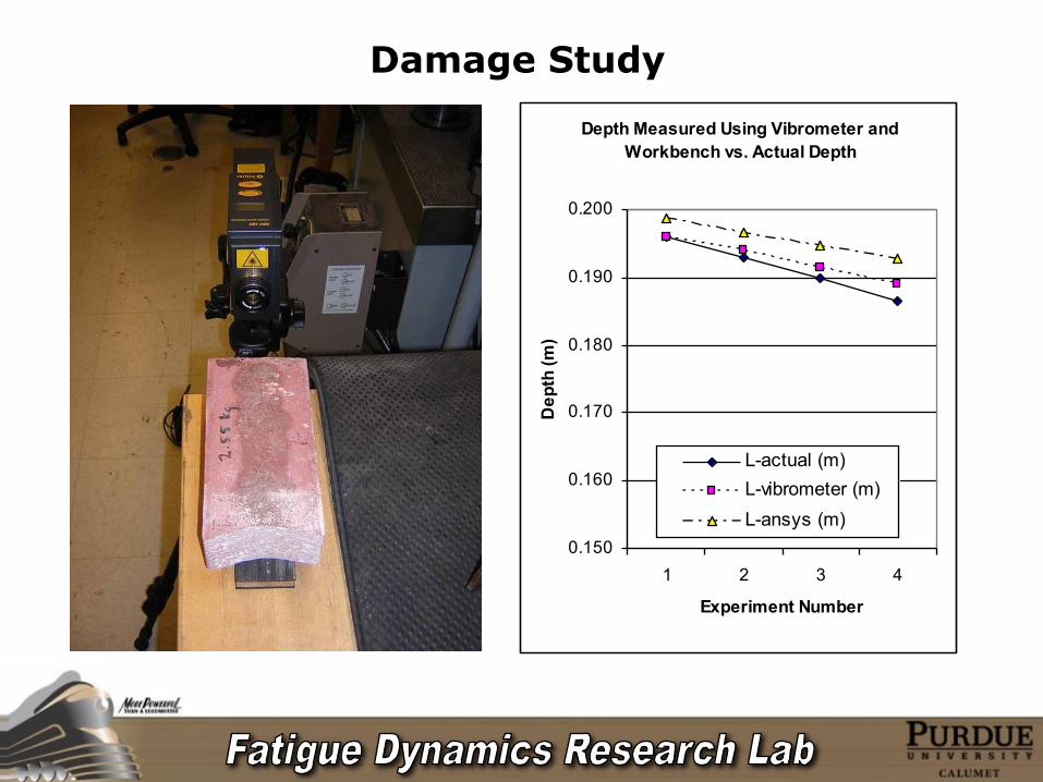
Damage Study Depth Measured Using Vibrometer and
Workbench vs. Actual Depth
0.150
0.160
0.170
0.180
0.190
0.200
1 2 3 4
Experiment Number
Dep
th (m
)
L-actual (m)L-vibrometer (m)L-ansys (m)
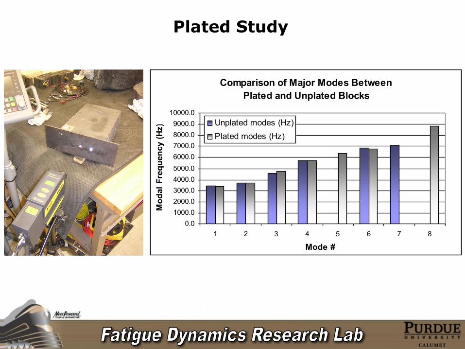
Plated Study
Comparison of Major Modes Between Plated and Unplated Blocks
0.01000.02000.03000.04000.05000.06000.07000.08000.09000.0
10000.0
1 2 3 4 5 6 7 8
Mode #
Mod
al F
requ
ency
(Hz) Unplated modes (Hz)
Plated modes (Hz)
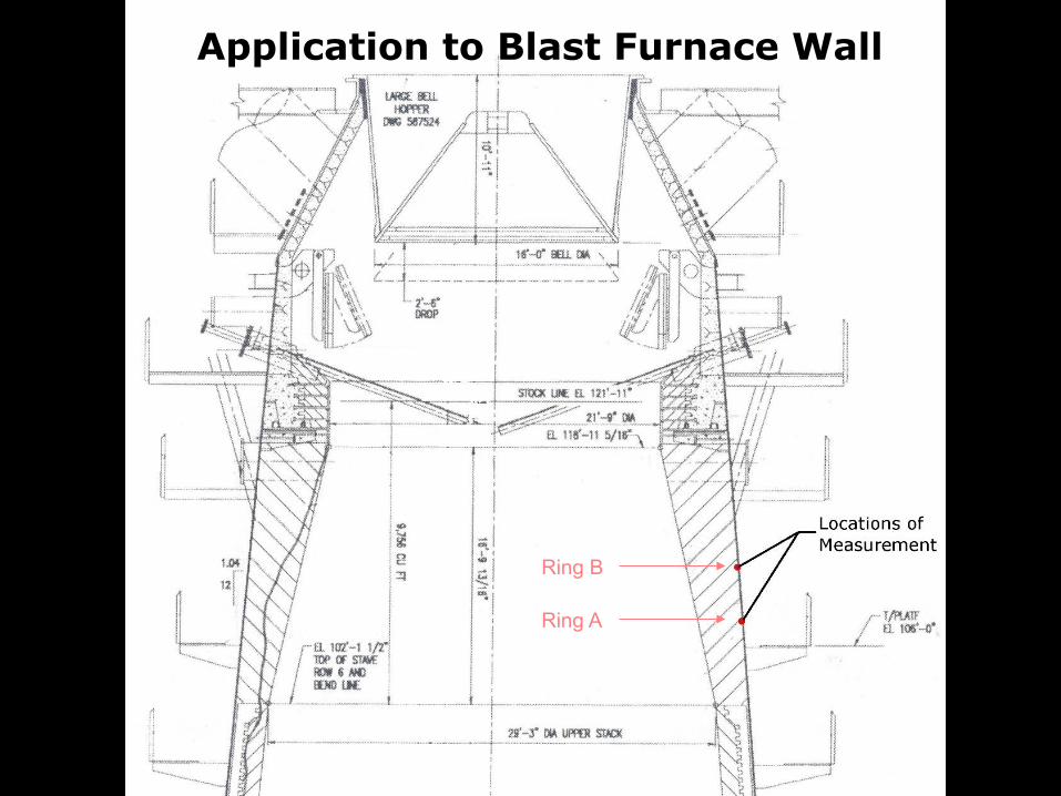
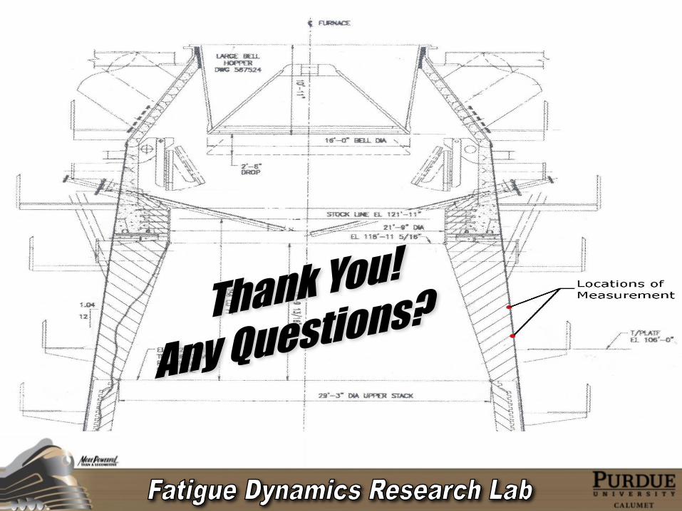
Application to Blast Furnace Wall
Ring B
Ring A
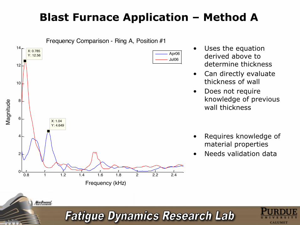
Blast Furnace Application – Method A
• Uses the equation derived above to determine thickness
• Can directly evaluate thickness of wall
• Does not require knowledge of previous wall thickness
• Requires knowledge of material properties
• Needs validation data
0.8 1 1.2 1.4 1.6 1.8 2 2.2 2.40
2
4
6
8
10
12
14
X: 0.785Y: 12.56
Frequency (kHz)
Mag
nitu
de
Frequency Comparison - Ring A, Position #1
X: 1.04Y: 4.649
Apr06Jul06
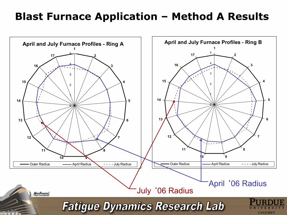
Blast Furnace Application – Method A Results
April and July Furnace Profiles - Ring A
0
1
2
3
4
51
2
3
4
5
6
7
8
910
11
12
13
14
15
16
17
Outer Radius April Radius July Radius
April and July Furnace Profiles - Ring B
0
1
2
3
4
51
2
3
4
5
6
7
8
910
11
12
13
14
15
16
17
Outer Radius April Radius July Radius
July ‘06 Radius April ‘06 Radius
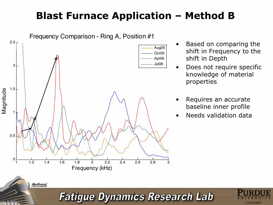
Blast Furnace Application – Method B
• Based on comparing the shift in Frequency to the shift in Depth
• Does not require specific knowledge of material properties
• Requires an accurate baseline inner profile
• Needs validation data
1 1.2 1.4 1.6 1.8 2 2.2 2.4 2.6 2.8 30
0.5
1
1.5
2
2.5
Frequency (kHz)
Mag
nitu
de
Frequency Comparison - Ring A, Position #1
Aug05Oct05Apr06Jul06
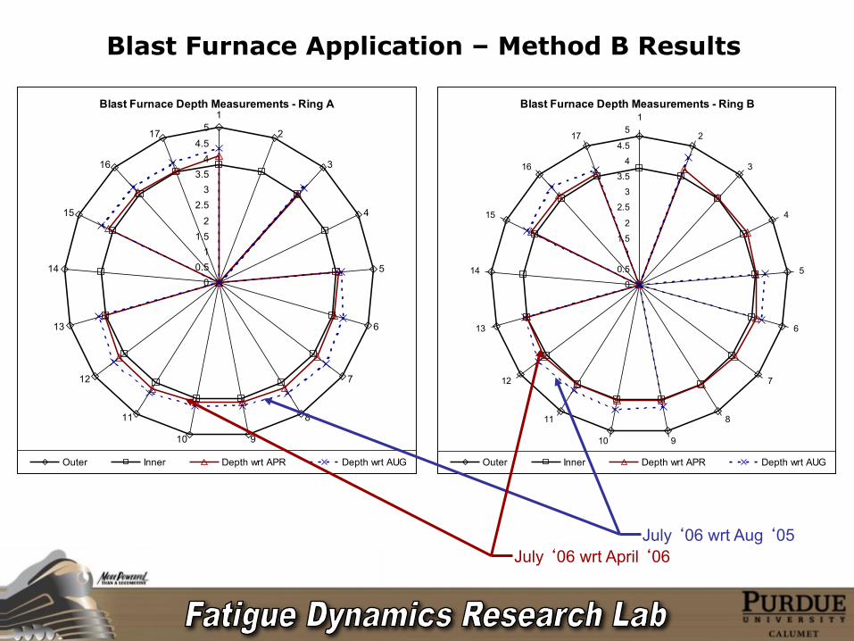
Blast Furnace Application – Method B Results
Blast Furnace Depth Measurements - Ring A
00.5
11.5
22.5
33.5
44.5
51
2
3
4
5
6
7
8
910
11
12
13
14
15
16
17
Outer Inner Depth wrt APR Depth wrt AUG
Blast Furnace Depth Measurements - Ring B
0
0.5
1
1.5
2
2.5
3
3.5
4
4.5
51
2
3
4
5
6
7
8
910
11
12
13
14
15
16
17
Outer Inner Depth wrt APR Depth wrt AUG
July ‘06 wrt April ‘06 July ‘06 wrt Aug ‘05
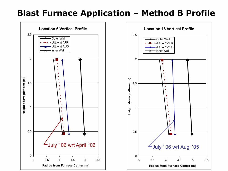
Blast Furnace Application – Method B Profile
Location 6 Vertical Profile
0
0.5
1
1.5
2
2.5
3 3.5 4 4.5 5 5.5
Radius from Furnace Center (m)
Hei
ght a
bove
pla
tfor
m (m
)
Outer WallJUL w rt APRJUL w rt AUGInner Wall
Location 16 Vertical Profile
0
0.5
1
1.5
2
2.5
3 3.5 4 4.5 5 5.5
Radius from Furnace Center (m)
Hei
ght a
bove
pla
tfor
m (m
)
Outer WallJUL w rt APRJUL w rt AUGInner Wall
July ’06 wrt April ‘06 July ’06 wrt Aug ‘05
Recommendations
• This project displays promising results • Further validation is required • Further analysis should be made of Rings A and B at BF #3
– Establish baseline wall thickness data – Install thermocouples so that CFD analysis can be performed for
comparison • Obtain and perform analysis of precise materials that
compose the wall at measurement locations of BF #3
Conclusions
• This project was devoted to researching the application of the acoustic method for wall thickness monitoring
• Though further validation is required, results strongly indicate that the wall thickness of a blast furnace can be monitored using acoustics

Acknowledgements
Dr. Yulian Kin Eric S. Roades
Krasimir Zahariev Bernard W. Parsons II
Pete Peters & CMET Dept. Rick Rickerson & METS Dept.
21st Century Science and Technology Fund of Indiana Mittal Steel
Et. Al.