Embed Size (px)
Citation preview
October 4, 2016
Santa Clara Convention Center
Mission City Ballroom
Mechanisms for
Trusted Code Execution
Bob Waskiewicz
Recap IoT Security

Root of Trust
• Root of Trust
• Whole process depends on the integrity of the first module
• First module protected by hardware: Trust Anchor
3
Hardware Loader RTOS Application
Verify
Trust
Trust Anchor
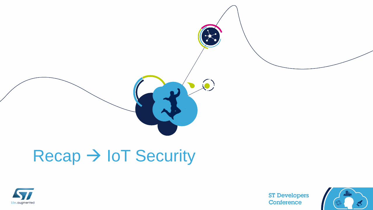
Application Code 4
• Application code should be written and executed in a secure manner
• Start with security coding ‘Best Practices’ including software layering
• Use of appropriate mechanisms:
• Use derived keys
• Use process partitioning as appropriate
• Chain of Trust
• At start-up, each ‘stage’ verifies the integrity and/or authenticity of the next stage
• Chaining of HASH/integrity checked
• Only if check is OK, control is transferred to the next stage, otherwise system is halted
Secure Execution
Secure Storage 5
• Access to data must be carefully controlled and restricted to
authorized persons, machines, and processes
• Data at rest – protected
• Encrypt as necessary; All keys, master keys, session keys used for secure
communications, passwords etc.
• Encrypt sensitive application data
• Encrypt sensitive customer personal data
• Destroy keys no longer valid.
Data at Rest

Communications 6
• IoT ecosystem relies on confidential and trusted communications
• Data integrity
• Encryption end to end
• Device authentication
• Using Public Key Infrastructure (PKI) solutions
Data in Motion

IoT AttacksLocal Versus Remote
Product Invasive
• Uncontrolled state device
• Fault Injection
Glitch on power &
clock for code dump
Silicon Invasive
• Probing
• Reverse Engineering
Extraction of key
Non Invasive
• Logical attacks
• Side channel attacks
ATTACKS COST and EXPERTIZE
COMPONENT and SYSTEM SECURITY LEVEL
8

ARM Cortex® / STM32
Security Features
IoT Devices 9
Three Types of CPU Based Devices• MPU: Microprocessors
• High-performance CPUs (>GHz) using lots of memory (non-volatile and volatile) >GB
• Large Storage
• Typically running complex file operating systems/General computing devices
• MCU: Microcontrollers• Lower performing CPUs (~MHz) with self contained internal memories (< few MB)
• Typically running native code or RTOS
• Focused Application Devices
• Secure MCU: Secure Microcontrollers• Sub-class of MCUs, limited peripheral set
• Design for security and contain specific hardware counter attack measures
• Use certifiable processes from inception to manufacturing
• Limited to specific security applications (SmartCard, SIM, eSE, Authentication)

STM32L476 MCU 10• Processor
• 80 MHz ARM® Cortex® M4
• Memory Support
• Internal 1MB Flash
• Internal 128K SRAM
• QuadSPI
• External Memory Controller
• Connectivity
• I2C, SPI, USB
• Analog
• Control
Internal
Memory

Cortex®-M Cores
•
M0/M0+, M3, M4, and M7
14

ST Has Licensed ALL Cortex®-M Cores 12
Source: ARM

Cortex®-M0 / M0+ Microarchitecture 13
• Thumb-2 Technology
• Integrated configurable NVIC
• Microarchitecture
• 3-stage pipeline with branch speculation
• 1x AHB-Lite Bus Interfaces
• Configurable for ultra low power
• Deep Sleep Mode, Wakeup Interrupt Controller
• Flexible configurations for wider applicability
• Configurable Interrupt Controller
• Optional Debug and Trace
• M0, No Memory Protection Unit
• M0+, Optional Memory Protection Unit
ARMv6M Architecture
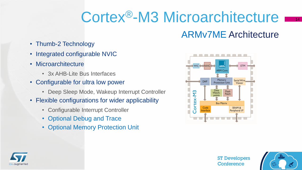
Cortex®-M3 Microarchitecture 14
• Thumb-2 Technology
• Integrated configurable NVIC
• Microarchitecture
• 3x AHB-Lite Bus Interfaces
• Configurable for ultra low power
• Deep Sleep Mode, Wakeup Interrupt Controller
• Flexible configurations for wider applicability
• Configurable Interrupt Controller
• Optional Debug and Trace
• Optional Memory Protection Unit
ARMv7ME Architecture
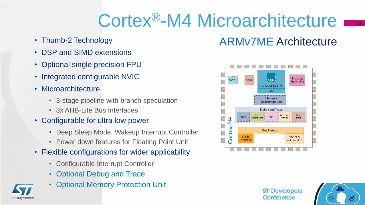
Cortex®-M4 Microarchitecture 15
• Thumb-2 Technology
• DSP and SIMD extensions
• Optional single precision FPU
• Integrated configurable NVIC
• Microarchitecture
• 3-stage pipeline with branch speculation
• 3x AHB-Lite Bus Interfaces
• Configurable for ultra low power
• Deep Sleep Mode, Wakeup Interrupt Controller
• Power down features for Floating Point Unit
• Flexible configurations for wider applicability
• Configurable Interrupt Controller
• Optional Debug and Trace
• Optional Memory Protection Unit
ARMv7ME Architecture

Cortex®-M7 Microarchitecture 16
• Thumb-2 Technology
• DSP and SIMD extensions
• Optional Double precision FPU
• Dual-issue superscalar architecture
• Microarchitecture
• 6-stage pipeline with branch speculation
• AXI-M Bus Interface with cache memory
• Configurable for ultra low power
• Deep Sleep Mode, Wakeup Interrupt Controller
• Power down features for Floating Point Unit
• Flexible configurations for wider applicability
• Configurable Interrupt Controller
• Optional Debug and Trace
• Optional Memory Protection Unit
ARMv7ME Architecture

Today - STM32 Portfolio 17
8 product series / 31 product lines More than 30 product lines
398 CoreMark
120 MHz
150 DMIPS
Ultra-low-power
Mainstream
Cortex-M0
Cortex-M0+ Cortex-M3 Cortex-M4 Cortex-M7
106 CoreMark
48 MHz
38 DMIPS
245 CoreMark
72 MHz
90 DMIPS
177 CoreMark
72 MHz
61 DMIPS
608 CoreMark
180 MHz
225 DMIPS
High-performance 1082 CoreMark
216 MHz
462 DMIPS
75 CoreMark
32 MHz
26 DMIPS
93 CoreMark
32 MHz
33 DMIPS
273 CoreMark
80 MHz
100 DMIPS

STM32 Family vs. Security Features 18
ST
Family
Security Features
De
bu
g
Acce
ss
Po
rt
RE
SE
T
Regis
ter
FL
AS
H
WR
P
FL
AS
H
Ma
ss
ER
AS
E
Ta
mp
er
Pin
s
CR
C
Hard
wa
re
96
-Bit
Uniq
ue
ID
Cry
pto
Lib
rary
Su
pp
ort
Me
mo
ry
Pro
tectio
n
Unit
(MP
U)
FL
AS
H
RD
P
TR
NG
AE
S
Hard
wa
re
Acce
lera
tor
FL
AS
H
PC
RO
P
HA
SH
Hard
wa
re
Acce
lera
tor
Firew
all
SR
AM
RD
P
Sys C
lock
(MH
z)
AR
M
Cort
ex
®
STM32 F1 72 M3
STM32 F3 72 M4
STM32 F0 48 M0
STM32 L1 32 M3
STM32 F2 120 M3
STM32 F4 180 M4
STM32 F7 216 M7
STM32 L0 32 M0+
STM32 L4 80 M4
*AR
M
TR
M
RM
xxxx
AN
42
46
RM
xxxx
AN
33
71
RM
xxxx
UM
192
4
AN
48
38
*AN
17
9
AN
42
46
AN
42
30
UM
192
4
AN
42
46
AN
47
01
AN
47
58
UM
192
4
AN
47
29
AN
47
29
Application Note# (AN)/User Manual# (UM)/Reference Manual#(RM) (www.st.com/mcu) (*infocenter.arm.com)

ARM Memory Protection Unit 19
Overview
Main()@ addr:
RO
Region 0
Region 3
Main Stack
MSP@ addr:
Privileged RW
PSP@addr:
Unprivileged RW
MPU example
Bootloader@ addr:
No Access
Region 1
Region 4
Process Stack
• Optional feature available on Cortex™-M cores
• Enforce privilege rules on read / write / execute only or no-access
• Memory areas defined by regional (8 Regions) parameters for memory isolation
• Upon violation, core generates a hard-fault or core “lock-up”
ARM Memory Protection Unit 20
Why Use an MPU ?
• Prevent processes from accessing memory that has not been allocated to them.
• Protect applications from a number of potential error such as the detection of
stack overflows
• Protect from invalid execution by RTOS tasks and protect data from corruption
• Protect system peripherals from unintended modification

ARM Cortex® Debug 21
• Serial Wire Debug or IEEE JTAG Debug
• Embedded break / watch capabilities for easy Flashed application debugging
• Includes a Serial Wire Viewer for low bandwidth data trace
• Includes an Embedded Trace Module for system core clock debugging
• DAP is ALIVE ALL the time After RESET, when core enters low power mode, and when
non-core security features are enabled
• The BKPT assembly instruction will cause the core to enter Debug state
Debug Access Port (DAP)
JTAG SWD
More pins availablefor the application

STM32 Firewall 22
Overview
• Creates a specific “trust area” of code with own memory isolated from all other code areas
• Has a single gateway interface to enter the Firewall. Any access other than the proscribed gateway interface results in a system reset
• Ideal for protecting algorithmic IP separate from the rest of the internal application, and performing security sensitive operations (i.e. HASHing)
• Intrusive detection into a protected area generates a MCU reset
• Includes DMA and/or Interrupt intrusions
• Configured at Start and remains active until the next system reset
GP-DMACortex-M
Bus Matrix
Bridge AHB/APBSRAMNV Memory
FIREWALL
Volatile Data
Code
Data
Reset Event

STM32 Memory Features 23
• Readout Protection (RDP)
• Level 0: no readout protection
• Level 1: memory readout protection
• Level 2: chip readout protection
• Proprietary code Read Out Protection (PcROP)
• Specific configurable area
• 1 each per Flash sector
• Write protection (WRP)
• 1 each per Flash / SRAM* sector
Overview
Flash code is protected when
accessed through the JTAG
interface or when the Boot is
different from Flash memory
Flash code is only
executable, not readable
Flash code is protected from
unwanted write/erase operations

STM32 Memory Features 24
• Readout Protection Level 0 (no protection, factory default)
• All operations (R/W/Erase) are permitted on Flash memory, SRAM, and Backup Domain
• Readout Protection Level 1
• If the selected boot mode is User Flash and if no debugger access is detected (no JTAG):-
• All operations (R / W / Erase) are permitted on the Flash memory, SRAM, and Backup registers
• If the selected boot mode is not user Flash, or if a debugger access is detected (JTAG):-
• ALL operations (R / W / Erase) to Flash memory, SRAM, and Backup registers are blocked and a
hard fault interrupt is generated.
Readout Protection (RDP)

STM32 Memory Features 25
• Readout Protection Level 2 (JTAG fuse blown)
• All protections provided by Level 1 are active
• Boot from RAM or System memory is no longer possible (only from User Flash memory)
• The physical JTAG interface is disabled
• Factory Failure Analysis Report is limited, thus ensuring there is no factory backdoor
• If the selected boot mode is User Flash memory
• All operations (R/W/Erase) are permitted on the Flash memory, backup registers and SRAM
• Level 2 CANNOT be reversed
Readout Protection (RDP)

STM32 Memory Features 27
• Level 0
• Option byte mods are allowed
• Can transition to Level 1 or Level 2
• Level 1
• Option byte mods are allowed.
• Can transition to Level 0 or Level 2
• Level 0 Mass erase of user Flash, backup registers and
newer device SRAM sector
• Level 2
• Option bytes are frozen
• No transition possible
RDP Transition SchemeLevel 0
RDP = 0xAA
Level 1
RDP ≠ 0xCC
RDP ≠ 0xAA
Level 2
RDP = 0xCC
Permanent
State

STM32 Memory Features 28
Proprietary code Read Out Protection (PcROP)
Protect confidentiality of software
IP code whatever the RDP level
• Prevents malicious software or a
debugger from reading sensitive code
• The PCROP Flash memory area is
executable only
• R / W / Erase operations are not permitted
• Third-parties can develop and sell
specific software IPs for STM32 MCUs
• Customers may use these software
IPs for development with / in their own
application code

STM32 Memory Features 29
• PCROP : Prevents snooping execution, however, the results of
execution (variables, core registers) are not protected.
• PCROP : RAM not protected
• Firewall : Dynamic execution protection, (open / close)
Firewall vs. PCROP

STM32 Memory Features 30
• The Flash write-protected area is defined on a per sector basis via
the STM32 option bytes setting.
• In newer STM32 devices the WRP area is defined by “start” and
“end” addresses
• In the STM32L4 devices, a SRAM section is write protectable
Flash and SRAM Write Protection (WRP)
STM32 96-bit Unique ID 31
• Unique Device Identifier installed at the ST Factory
• Provides a reference number unique for any STM32
• It will not repeat for many years
• The Unique ID is suited for:-
• Generating a serial number via an algorithm
• Combining with cryptographic primitives to increase security before
programming STM32 Flash, key derivation.
• Used as part of device authentication during secure boot process
Features
STM32 Cyclical Redundancy Check 32
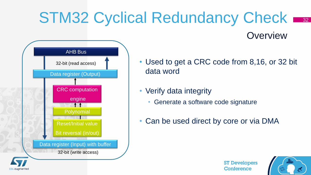
• Used to get a CRC code from 8,16, or 32 bit
data word
• Verify data integrity
• Generate a software code signature
• Can be used direct by core or via DMA
Overview
CRC computation
engine
Data register (Input) with buffer
Data register (Output)
AHB Bus
32-bit (read access)
32-bit (write access)
Reset/Initial value
Bit reversal (in/out)
Polynomial

STM32 Advanced Encryption Standard 33
• Hardware acceleration that transforms
original plaintext to unreadable ciphertext
• Supports
• Several standard operation modes and
key sizes
• Supports several standard AES chaining
modes
• Supports data swapping
• Supports DMA
• Reduces CPU time:-
• typical 100 -200 sysclk cycles
Overview
Cipher
Cipher Key
Encryption direction
Decryption direction
Plaintext Ciphertext

34
STM32 Advanced Encryption Standard 42
•
Block Diagram
DMA request for
outgoing data transfer
AES Accelerator
Data
In
Data
ou
t
Data
sw
ap
pin
g
Data
sw
ap
pin
g
ECB
DMA request for
incoming data transfer
GCM
CBC
GMAC
CTR
CMAC
AES chaining mode
Encryption Key derivation
AES operation mode
Decryption Key derivation +
decryptionKey: 128- 256-bit
NIST FIPS 197 compliant implementation of AES

35
STM32 HASH ProcessorOverview
MD5
HASH
HASH Processor
Inp
ut
FIF
O
Da
ta s
wa
pp
ing
HMAC
Message Digest
H0..H78x32bit
16
x 3
2b
it
SHA-1, SHA-224 SHA-256
• Hardware acceleration that
transforms original plaintext to an
unreadable Message Digest
• Supports
• Supports several HASH standards
• Supports data swapping
• Supports DMA
• Reduces CPU time:-
• typical 50-66 sysclk cycles
Compliant with:FIPS Pub 180-2
Secure HASH Standards (SHA-1*, SHA-224, SHA-256)
IETF RFC 1321 (MD5*)
43
STM32 Crypto Library 36
• STM32 Firmware Crypto Library V3.1.0
• All STM32 series supported: STM32F0, STM32F1, STM32F2, STM32F3, STM32F4,
STM32F7, STM32L0, STM32L1 and STM32L4
• All algorithms are based on firmware implementation without using any hardware
acceleration
• The STM32 Firmware Crypto Library is distributed by ST as an object code library,
accessed by the user application through an API
• The library is compiled for Cortex® M0, M0+, M3, M4, and M7 cores
Software ONLY

STM32 Crypto Library 37
• STM32 Hardware Acceleration Crypto Library V3.1.0
• Support all STM32 series with hardware acceleration (AES and/or HASH): STM32F2,
STM32F4, STM32F7, STM32L0, STM32L1 and STM32L4
• Support the algorithms based on firmware implementation with hardware acceleration
(Hybrid)
• The STM32 Hardware Acceleration Crypto library is distributed by ST as an object code
library, accessed by the user application through an API
• The library is compiled for Cortex® M0, M0+, M3, M4, and M7 cores
Hardware Acceleration

STM32 Crypto Library 38
CAVP FIPS Certified
NEW
Ecosystem
X-CUBE-CRYPTOLIB library
is ready for use in security-conscious STM32-based applications
• Helps customers prove the security of their new products
quickly and cost-effectively
• Ready for use STM32-based applications including IoT
• Removes the burden of algorithm validation
• Allows OEMs to fasten their security certification process
• Includes all the major algorithms for encryption, hashing,
message authentication, and digital signing

39
• 32-bit Random Number Generator based on a noise source
• A 32-bit random number can be generated at an average frequency of AHB / xx
• Three Flags:-
• Valid random data is ready
• An abnormal sequence occurs on the seed
• A frequency error is detected when using a PLL48 RNG clock source
• One interrupt
• To indicate an error (an abnormal seed sequence or a frequency error)
Features
STM32 True Random Number Generator

STM32 True Random Number Generator 40
Block Diagram
RNG
RNG_CLK
FlagsInterrupt
Enable bit
RNG interrupt to NVIC
IM DRDY
LFSR
(Linear Feedback
Shift register)
Analog seed
32-bit
random data
register
Clock checker
Fault detector
CEISSEISSECS CECS
Error management

STM32 Reset 41
• Manages three types of reset:-
• System reset
• Power reset
• Backup domain reset
• Peripherals have individual reset control bits in the RCC_CSR register
Features
Safe and flexible reset management without external components

STM32 Reset 42
Source
Filter
VDD
RPU
PULSE
GENERATOR
(min 20µs)
SYSTEM RESET
NRST
WWDG RESET
IWDG RESET
Software RESET
BOR RESET
Low power management RESET
External
RESET
Firewall RESET
Option byte loading RESET
• No external components are needed due to internal filter and power monitoring

Anti Tamper 43
• Backup Domain Contains
• A Calendar RTC
• xx Data Bytes, Backup SRAM
• Separate 32kHz oscillator for RTC
• Tamper Detection Pins
• RESETs all RTC backup registers and
Backup SRAM
• Time stamp event
Backup Domain
Backup Domain
32KHz OSC
(LSE)
RTC
xx Register Bytes
SRAM*
RCC BDSR
reg
Wakeup
LogicIWWDG
VBAT
VDD
power switch
RTC_TAMP2
RTC_TAMP3
Anti-tamper
switches
Tamper
detection
RTC_TAMP1
Optional
filtering
capacitors
RESET & Interrupt
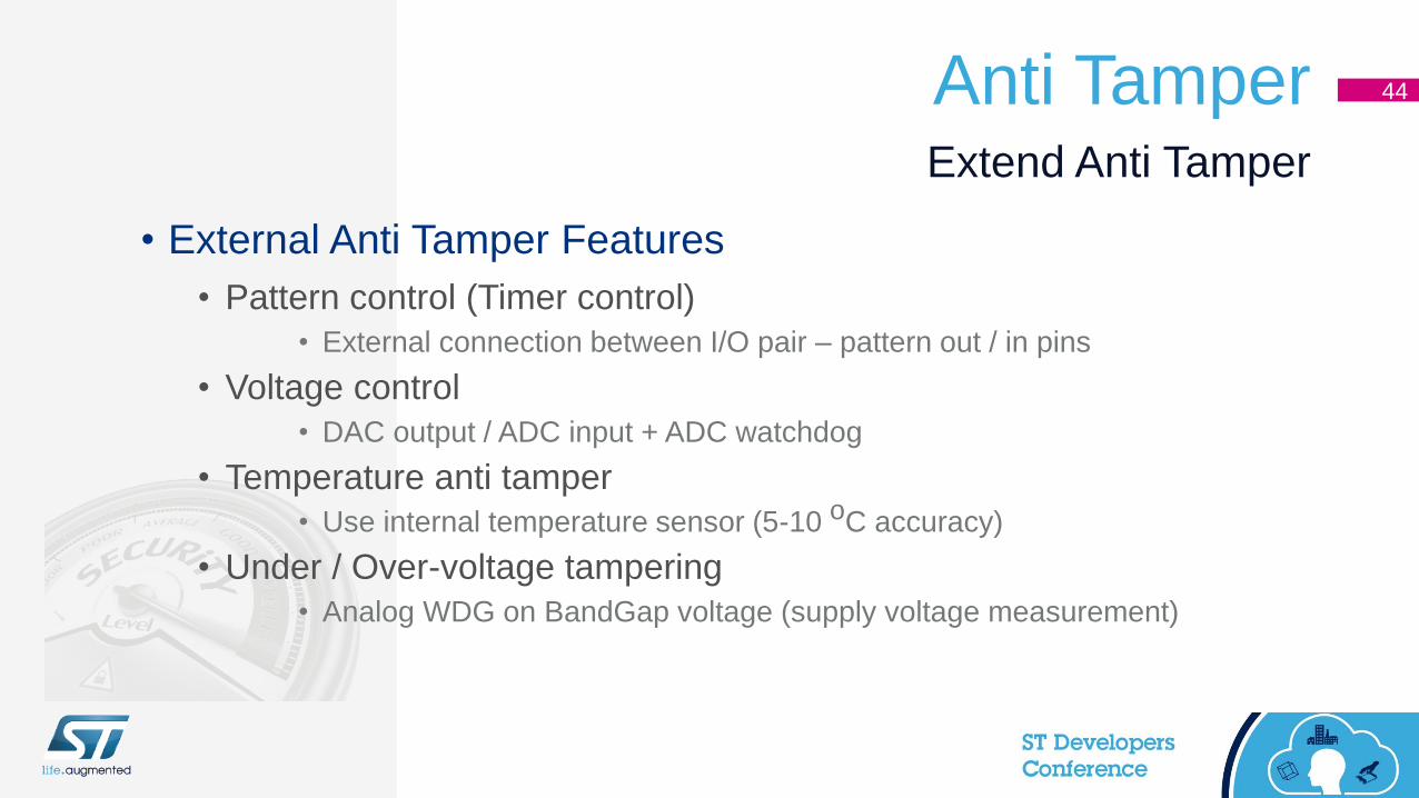
Anti Tamper 44
• External Anti Tamper Features
• Pattern control (Timer control)
• External connection between I/O pair – pattern out / in pins
• Voltage control
• DAC output / ADC input + ADC watchdog
• Temperature anti tamper
• Use internal temperature sensor (5-10 oC accuracy)
• Under / Over-voltage tampering
• Analog WDG on BandGap voltage (supply voltage measurement)
Extend Anti Tamper
STM32 Secure Firmware Update OverviewAN4023

STM32 Boot Loader OptionsNative(ICP) and IAP Methods
ROM
Boot loader
UART
USB
JTAG/SWD
FLASH
IAP
Boot loader
Application
Firmware
USB
Device
2
Bluetooth LE
Radio
3
JTAG
Programmer
1
55

Custom Boot Loader 47
• An alternative to ICP load mechanisms giving
additional flexibility
• Tailored to the application
• Can use non-published load methods
• Ability to use other interfaces rather than the native
load interfaces
• Must be done when using STM32 Level 2 Security
Benefits
Level 2

AN4023 Secure Firmware Update
• Secure Loader Installation (1st Trust Event)
• Secure Firmware Insertion (ST Factory / OEM / CM / Distributor)
• Public Key installation
• Lock down the device (Level 2)
• Provisioning (2nd Trust Event)
• Private key installation (OEM / CM / Distributor)
• Done as part of a Hardware Secure Module (HSM)
• Secure Boot
• Secure Loader
Overview
57
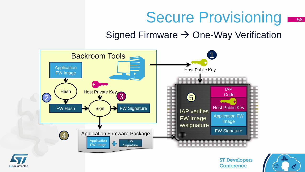
Secure Provisioning 58
Signed Firmware One-Way Verification
Application FW
Image
FW Signature
Backroom Tools
Application
FW Image
FW SignatureFW Hash
Hash
Sign
Application Firmware Package
Application
FW ImageFW
Signature
1
2 3
4
5
IAP verifies
FW Image
w/signature
IAP
CodeHost Private Key
Host Public Key
Host Public Key

Secure Provisioning 50
Signed Firmware Two-Way Verification
Backroom Tools
Application FW
Image
FW Signature
IAP
Code
Application Firmware Package
Application
FW ImageFW
Signature
1
2
3
IAP verifies
FW Image
w/signature.
Signs image
+ dev id
Device ID
Host verifies
FW + Dev ID
signature
FW+Dev ID
Signature4
Host signs
FW image
5
Host Public Key
Host Private Key
IAP Public Key
IAP Private Key

STM32 Secure Boot
• Secure Boot Application
• Authenticate the STM32 device
• Enable the IWDG
• RESET Recovery Check
• Disable the ARM DAP Configuration
• Initialize the Firewall and / or MPU
• To HASH The Loader firmware
• Initialize the Flash and SRAM (zero)
• At each step a GO / NO-GO decision is made by the Boot Loader
Best Coding Practices
60

STM32 Secure LoaderArchitecture
62

STM32 Secure LoaderFlow Chart
62

Demo

ST Solutions for Security in IoT AN4023, L476 Nucleo Demo
Secure Firmware Upgrade from HSM
Use of proven code from proven source
Key provisioning chain
STM32 Secure Upgrade Demo
Secure Firmware Upgrade
Use of proven code
Key provisioning chain
Main Features• Download and upgrade of encrypted binary
• Decryption and authenticate before Flashing
• Close control of key chain
• Use of Ymodem but can be USB or IP based
64

56

57