Embed Size (px)
Citation preview
罗杰斯公司在高性能特种电子材料领域中享有盛名。作为开发和制造高性能电路材料的先驱,罗杰斯公司为
客户不断改革创新了将近0年;产品覆盖对技术要求最苛刻的电路应用领域。微波电路的市场在过去几十年里得
到很大的发展,从应用波导的军用市场到低成本基片的商用市场,Rogers公司总是领先于微波基板的技术领域并
提供微波板材的更多选择。
Contents
High Frequency Laminate Properties ............................................................................................................................................................. 2
Metal Claddings ...................................................................................................................................................................................................... 3
Ordering Information ........................................................................................................................................................................................... 4
ULTRALAM® 3000 Liquid Crystalline Polymer Circuit Material ............................................................................................................... 5
ULTALAM® 3908 Bondply ..................................................................................................................................................................................... 9
RO4000® Series High Frequency Circuit Materials ..................................................................................................................................... 13
RO4500™ Series Cost Performance Antenna Grade Laminates ............................................................................................................. 19
RO4730™ Series LoPro™ Antenna Grade Laminates .................................................................................................................................. 21
RO3730™ Antenna Grade Laminates .............................................................................................................................................................. 23
Data Sheet and Processing Guidelines for RO4403™, RO4450B™ and RO4450F™ Prepregs ....................................................... 25
Preliminary Data sheet - RO4233® LNB Laminates ..................................................................................................................................... 29
RO3000® Series High Frequency Circuit Materials ..................................................................................................................................... 30
RO3035™ High Frequency Circuit Materials ................................................................................................................................................. 33
RO3200™ Series High Frequency Circuit Materials .................................................................................................................................... 35
3001 Bonding Film Properties and Lamination Techniques ................................................................................................................... 37
RT/duroid® 5870/5880 High Frequency Laminates ................................................................................................................................... 41
ULTALAM® 2000 Woven Glass Reinforced Microwave Laminate ........................................................................................................... 43
RT/duroid® 6002 High Frequency Laminates ............................................................................................................................................... 45
RT/duroid® 6006/6010 High Frequency Laminates ................................................................................................................................... 47
TMM Temperature Stable Microwave Lamiinate ........................................................................................................................................ 49
Prod
uct
Com
posit
ion
Diel
ectri
c(1)
Con
stan
ter
@ 1
0 G
Hz(T
ypic
al)
Diss
ipat
ion(1
)
Fact
or TA
N δ
@ 1
0 G
Hz(T
ypic
al)
Ther
mal
(2)
Coe
ffi cie
nt o
f er
-50°
C to
150
°Cpp
m/°
C(T
ypic
al)
Volu
me
Resis
tivity
Moh
mcm
(Typ
ical
)
Surfa
ceRe
sistiv
ityM
ohm
(Typ
ical
)
Youn
gs M
odul
us(3
)
kpsi
(MPa
)(T
ypic
al)
Moi
stur
e(4)
Abs
orpt
ion
D24/
23%
(Typ
ical
)
Ther
mal
(5)
Con
duct
ivity
W/m
/°K
(Typ
ical
)
Coe
ffi cie
nt o
f The
rmal
Ex
pans
ion(6
)
0° -
100°
Cpp
m/°
C(T
ypic
al)
Dens
itygm
/cm
3
(Typ
ical
)
Peel
Stre
ngth
1 oz
(35 µm
)ED
C F
oil
lbs/
in, (
N/m
m)
(Typ
ical
)
Flam
mab
ility
Ratin
gUL
Lead
-Fre
ePr
oces
sC
apab
ility
Halo
gen
Free
PIM
dbc
rang
e(T
ypic
al)
ZY
XZ
YX
RO30
03™
PTFE
Cer
amic
(7) 3
.00
± 0.
040.
0013
1310
710
730
0(2
,068
)30
0(2
,068
)16
7(1
,151
)<0
.10.
5017
1724
2.1
17.6
(3.1
)94
V-0
YES
RO30
06™
PTFE
Cer
amic
6.15
± 0
.15
0.00
20-1
6010
310
330
0(2
,068
)30
0(2
,068
)21
1(1
,455
)<0
.10.
6117
1724
2.6
12.2
(2.1
)94
V-0
YES
RO30
10™
PTFE
Cer
amic
10.2
± 0
.30
0.00
23-2
8010
310
330
0(2
,068
)30
0(2
,068
)24
4(1
,682
)<0
.10.
6617
1724
3.0
13.4
(2.4
)94
V-0
YES
RO30
35™
PTFE
Cer
amic
3.50
± 0.
050.
0017
-50°
to 1
0°C
-34
107
107
300
(2,0
68)
300
(2,0
68)
181
(1,2
48)
<0.1
0.50
1717
242.
19.
1(1
.6)
94 V
-0YE
S10
°C to
150
°C-1
1
RO32
03™
PTFE
Cer
amic
Rein
forc
ed W
oven
Gla
ss(7
) 3.0
2 ±
0.04
0.00
1613
107
107
140
(965
)14
0(9
65)
129
(889
)<0
.10.
5013
1358
2.1
10 (1.7
)94
V-0
YES
RO32
06™
PTFE
Cer
amic
Rein
forc
ed W
oven
Gla
ss6.
15 ±
0.1
50.
0027
-212
107
107
140
(965
)14
0(9
65)
192
(1,3
24)
<0.1
0.63
1313
342.
77
(1.3
0)94
V-0
YES
RO32
10™
RO37
30™
PTFE
Cer
amic
Rein
forc
ed W
oven
Gla
ss
PTFE
Cer
amic
10.2
± 0
.50
0.00
27-4
5910
4
3.00
±0.0
6
3.00
±0.0
8
3.3±
0.08
107
1.4
X 10
135.
5 X
1012
107
1112
652.
10.
0016
0.00
33
0.00
20
-22 23
104
140
(965
)14
0(9
65)
223
(1,5
38)
<0.1
0.81
1313
343.
013 (2.4
)
1.8
7.7
(10.
5)
94 V
-0YE
S
RO40
03C
™Hy
droc
arbo
n C
eram
icPr
oces
sD
esig
n
(8) 3.
38 ±
0.0
53.
550.
0027
+40
1.7
X 10
104.
2 X
109
3,70
0(2
5,51
0)3,
900
(26,
889)
841
(5,8
00)
0.06
0.64
1114
461.
86.
0(1
.1)
N/A
YES
YES
N/A
YES
-154
-154
RO43
50B™
Hydr
ocar
bon
Cer
amic
RO45
33
RO47
30
™ ™
Hydr
ocar
bon
Cer
amic
Hydr
ocar
bon/
Clo
se M
icro
sphe
res
Proc
ess
Des
ign
3.48
± 0
.05
3.66
0.00
37+5
01.
2 X
109
5.7
X 10
9TB
D1,
664
(11.
473)
798
(5,5
00)
0.06
0.62
1416
351.
95.
2(0
.9)
94 V
-0YE
S
RO44
50B™
Hydr
ocar
bon
Cer
amic
Prep
reg
Thic
knes
s0.
0036
”3.
30 ±
0.0
50.
0040
-50
to 6
0°C
21
>2.5
X 1
0101.
9 X
108
N/A
N/A
N/A
0.05
0.60
1917
501.
86N
/A94
V-0
YES
0.04
0.
45
1917
401.
45(1
OZ
LoPr
o)N
on F
RYE
S0.
13
0.52
N/A
N/A
N/A
N/A
N/A
N/A
1311
371.
8N
/A0.
9N
/AYE
S15
0-16
00.
60
81-C°051ot 06
50.0 ± 45.3”400.0
**RO
4450
F™Hy
droc
arbo
n C
eram
ic
Prep
reg
3.52
± 0
.05
0.00
40TB
DTB
DTB
DN
/AN
/AN
/A0.
090.
6519
1750
1.83
N/A
94V-
0YE
S
RT/d
uroi
d®58
70PT
FE G
lass
Fib
er2.
33 ±
0.0
20.
0012
-115
2 X
107
2 X
108
189
(1,3
40)
185
(1,2
77)
120
(828
)0.
015
0.22
2228
173
2.2
20.8
(3.7
)94
V-0
YES
RT/d
uroi
d®58
80PT
FE G
lass
Fib
er2.
20 ±
0.0
20.
0009
-125
2 X
107
3 X
107
156
(1,0
76)
125
(863
)13
6(9
38)
0.01
50.
2031
4823
72.
222
.8(4
.0)
94V-
0YE
S
RT/d
uroi
d®60
02PT
FE C
eram
ic2.
94 ±
0.0
40.
0012
+12
106
107
120
(828
)12
0(8
28)
360*
(2,4
82)
0.1
0.60
1616
242.
18.
9(1
.6)
94V-
0YE
S
RT/d
uroi
d®62
02PT
FE C
eram
ic W
oven
G
lass
(9) 2.
94±
0.04
0.00
15+1
3**
1010
109
146
(1,0
07)
146
(1,0
07)
150
(1,0
35)
0.1
0.68
1515
302.
19.
1(1
.6)
94V-
0YE
S
RT/d
uroi
d®60
06PT
FE C
eram
ic6.
15 ±
0.1
50.
0027
-410
2 X
107
7 X
107
91 (628
)75 (517
)15
5(1
,070
)0.
050.
4847
3411
72.
714
.3(2
.5)
94V-
0YE
S
RT/d
uroi
d®60
10LM
PTFE
Cer
amic
10.2
± 0
.25
0.00
23-4
255
X 10
65
X 10
613
5(9
32)
81 (559
)31
1(2
,146
)0.
050.
7824
2447
3.1
12.3
(2.1
)94
V-0
YES
TMM
®3
Hydr
ocar
bon
Cer
amic
3.27
± 0
.032
0.00
20+3
73
X 10
9>9
x 1
091,
916
(13,
210)
1,91
6(1
3,21
0)74
2(5
,116
)(4
) 0.0
60.
7016
1620
1.78
5.7
(1.0
)N
/AYE
SYE
S
TMM
®4
Hydr
ocar
bon
Cer
amic
4.50
± 0
.045
0.00
20-1
5.3*
6 X
108
1 x
109
2,00
0*(1
3,79
0)2,
000*
(13,
790)
752
(5,1
85)
0.07
0.70
1414
202.
075.
7(1
.0)
N/A
YES
YES
TMM
®6
Hydr
ocar
bon
Cer
amic
6.00
± 0
.08
0.00
23-1
11
X 10
81
x 10
92,
200
(15,
168)
2,20
0(1
5,16
8)73
6(5
,075
)0.
060.
7216
1620
2.37
5.7
(1.0
)N
/AYE
SYE
S
TMM
®10
Hydr
ocar
bon
Cer
amic
9.20
± 0
.23
0.00
22-3
82
X 10
84
X 10
72,
400
(16,
547)
2,40
0(1
6,54
7)57
5(3
,964
)0.
090.
7616
1620
2.77
5.0
(0.9
)N
/AYE
SYE
S
TMM
®10
iHy
droc
arbo
n C
eram
ic9.
80 ±
0.2
450.
0020
-43
2 X
108*
4 X
107*
2,40
0*(1
6,54
7)2,
400*
(16,
547)
575*
(3,9
64)
0.16
0.76
1616
202.
775.
0(0
.9)
N/A
YES
YES
ULTR
ALA
M® 2
000
PTFE
Wov
en G
lass
2.40
- 2.
60
± 0.
040.
0019
-100
2 X
107
4 X
107
1,70
0(1
1,73
0)1,
300
(8,9
70)
N/A
0.03
0.24
1515
200
2.2
18.0
(3.2
)94
V-0
YES
ULTR
ALA
M® 3
000
Liqui
d C
ryst
allin
e Po
lym
er2.
90.
0024
TBD
1 x
1010
1 X
1012
2255
(327
)22
55(3
27)
N/A
0.04
0.5
1717
150
1.4
0.95
(5.2
)VT
M-0
YE
SYE
S
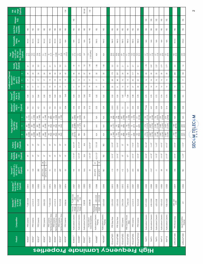
High Frequency Laminate Properties
Co
pp
er
Foil
Surf
ac
e R
ou
gh
ne
ssTe
nsi
le S
tre
ng
th
kp
si (
MP
a)
Elo
ng
atio
n%
Stre
ss C
rac
k R
esi
sta
nc
eTh
ick
ne
ss -
mils
Tre
ate
dSi
de
µin
(µ
m)
Un
tre
ate
dSi
de
µin
(µ
m)
¼ o
z (9µ
4.0
riaF
A/N
A/N
)4.
0( 5
1)
8.1(
07
d
etiso
pe
dort
celE )
m
½ o
z (1
7.5µ
7.0
riaF
0.0
2)
82
2( 0.
33
)4.
0( 5
1)
9.1(
57
detis
op
ed
ortc
elE )m
1 o
z. (
35µ
4.1
riaF
0.8
2)
70
2( 0.
03
)4.
0( 5
1)
4.2(
59
detis
op
ed
ortc
elE )m
2 o
z (7
0 µ
8.2
riaF
0.2
4)
12
2( 0.
23
)4.
0( 5
1)
9.2(
51
1d
etiso
pe
dort
celE )
m
½ (
17
.5µ
7.0
tn
elle
cxE0.
8)
83
1( 0.
02
)3.
0( 2
1)
4.1(
55
dell
oR )
m
1 o
z. (
35µ
4.1
tn
elle
cxE0.
31
)2
51(
0.2
2)
3.0(
21
)4.
1( 5
5d
ello
R )m
2 o
z (7
0µ
8.2
tn
elle
cxE0.
72
)3
91(
0.8
2)
3.0(
21
)4.
1( 5
5d
ello
R )m
Pla
tes
Allo
yM
ac
hin
ab
ility
Ten
sile
Str
en
gth
k
psi
(M
Pa
)D
en
sity
The
rma
l Co
nd
uc
tivity
Co
effi
cie
nt
of
The
rma
lEx
pa
nsi
on
pp
m/°
C
Alu
min
um
42
05
17.
2)
83
1( 0
2r
oo
P1
60
6
Bra
ss0
20
21
5.8
)1
13(
54
do
oG
eg
dirtra
C 0
3/0
7
Co
pp
er
71
09
39.
8)
24
2( 5
3d
oo
G ot ri
aF0
11
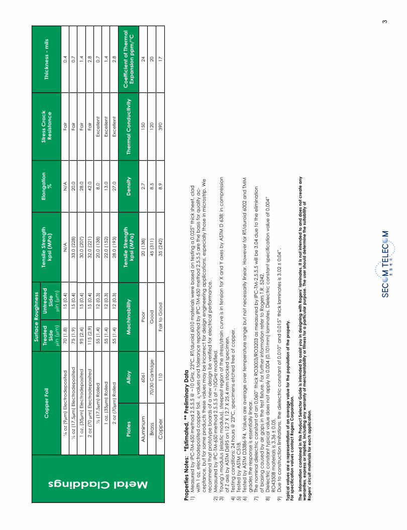
Metal Claddings
Pro
pe
rtie
s N
ote
s:
*Est
ima
ted
, **
Pre
limin
ary
Da
ta1)
M
ea
sure
d b
y IP
C-T
M-6
50 m
eth
od
2.5
.5.5
@ ~
10 G
Hz,
23°
C. R
T/d
uro
id 6
010
ma
teria
ls w
ere
ba
sed
on
te
stin
g a
0.0
25”
thic
k sh
ee
t, c
lad
w
ith 1
oz.
ele
ctr
od
ep
osit
ed
co
pp
er f
oil.
ε rva
lue
s a
nd
to
lera
nc
e re
po
rte
d b
y IP
C-T
M-6
50 m
eth
od
2.5
.5.5
are
th
e b
asis
for q
ua
lity
ac
-c
ep
tan
ce
, bu
t fo
r so
me
pro
du
cts
th
ese
va
lue
s m
ay
be
inc
orr
ec
t fo
r de
sign
en
gin
ee
ring
ap
plic
atio
ns,
esp
ec
ially
th
ose
in m
icro
strip
. We
re
co
mm
en
d t
ha
t p
roto
typ
e b
oa
rds
of a
ne
w d
esig
n b
e v
erifi
ed
for e
lec
tric
al p
erf
orm
an
ce
.2)
M
ea
sure
d b
y IP
C-T
M-6
50 m
eth
od
2.5
.5.5
at
~10
GH
z m
od
ifi e
d.
3)
You
ng
’s m
od
ulu
s (e
last
ic m
od
ulu
s), s
tee
pe
st re
gio
n o
f th
e s
tre
ss/s
tra
in c
urv
e is
in t
en
sion
for X
an
d Y
axe
s b
y A
STM
D 6
38: i
n c
om
pre
ssio
n
of Z
axi
s b
y A
STM
D69
5 o
n 1
2.7
X 1
2.7
X 2
5.4
mm
sto
cke
d s
pe
cim
en
.4)
Te
stin
g c
on
diti
on
s: 2
4 h
ou
rs @
23°
C, s
pe
cim
en
s e
tch
ed
fre
e o
f co
pp
er.
5)
Test
ed
by
AST
M C
518.
6)
Test
ed
by
AST
M D
3386
-94.
Va
lue
s a
re a
vera
ge
ove
r te
mp
era
ture
ran
ge
bu
t n
ot
ne
ce
ssa
rily
line
ar.
Ho
we
ver f
or R
T/d
uro
id 6
002
an
d T
MM
g
rad
es
the
resp
on
se is
ess
en
tially
lin
ea
r.7)
Th
e n
om
ina
l die
lec
tric
co
nst
an
t o
f an
0.0
60”
thic
k R
O30
03/R
O32
03 a
s m
ea
sure
d b
y IP
C-T
M-2
.5.5
.5 w
ill b
e 3
.04
du
e t
o t
he
elim
ina
tion
of b
iasin
g c
au
sed
by
air
ga
ps
in t
he
te
st fi
xtu
re. F
or f
urt
he
r in
form
atio
n re
fer t
o R
og
ers
T.R
. 524
2.8)
D
iele
ctric
con
stan
t typ
ical
val
ue d
oes n
ot a
pply
to 0
.004
(0.1
01m
m) l
amin
ates
. Die
lect
ric c
onst
ant s
peci
fi ca
tion
va
lue
of 0
.004
” R
O43
50B
ma
teria
ls is
3.36
± 0
.05.
9)
Du
e t
o c
on
stru
ctio
n li
mita
tion
s, t
he
die
lec
tric
co
nst
an
t o
f 0.0
10”
an
d 0
.015
” th
ick
lam
ina
tes
is 3.
02 ±
0.0
4”.
Typ
ica
l va
lue
s a
re a
rep
rese
nta
tion
of a
n a
vera
ge
va
lue
for t
he p
op
ula
tion
of t
he p
rop
ert
y.
For s
pe
cifi
ca
tion
valu
es
co
nta
ct R
og
ers
Co
rpo
ratio
n.
The
inf
orm
atio
n c
ont
ain
ed
in th
is P
rod
uct S
ele
cto
r Gui
de
is in
tend
ed
to a
ssis
t yo
u in
de
sig
ning
with
Ro
ge
rs’ l
am
ina
tes.
It is
no
t int
end
ed
to a
nd d
oe
s no
t cre
ate
any
w
arr
ant
ies,
exp
ress
or i
mp
lied
, inc
lud
ing
any
wa
rra
nty
of m
erc
hant
ab
ility
or fi
tne
ss fo
r a p
art
icul
ar p
urp
ose
. The
use
r sho
uld
de
term
ine
the
sui
tab
ility
of
Rog
ers
’ circ
uit m
ate
rials
for e
ac
h a
pp
lica
tion.
Co
pp
er
Foil
Surf
ac
e R
ou
gh
ne
ssTe
nsi
le S
tre
ng
th
kp
si (
MP
a)
Elo
ng
atio
n%
Stre
ss C
rac
k R
esi
sta
nc
eTh
ick
ne
ss -
mils
Tre
ate
dSi
de
µin
(µ
m)
Un
tre
ate
dSi
de
µin
(µ
m)
¼ o
z (9µ
4.0
riaF
A/N
A/N
)4.
0( 5
1)
8.1(
07
d
etiso
pe
dort
celE )
m
½ o
z (1
7.5µ
7.0
riaF
0.0
2)
82
2( 0.
33
)4.
0( 5
1)
9.1(
57
detis
op
ed
ortc
elE )m
1 o
z. (
35µ
4.1
riaF
0.8
2)
70
2( 0.
03
)4.
0( 5
1)
4.2(
59
detis
op
ed
ortc
elE )m
2 o
z (7
0 µ
8.2
riaF
0.2
4)
12
2( 0.
23
)4.
0( 5
1)
9.2(
51
1d
etiso
pe
dort
celE )
m
½ (
17
.5µ
7.0
tn
elle
cxE0.
8)
83
1( 0.
02
)3.
0( 2
1)
4.1(
55
dell
oR )
m
1 o
z. (
35µ
4.1
tn
elle
cxE0.
31
)2
51(
0.2
2)
3.0(
21
)4.
1( 5
5d
ello
R )m
2 o
z (7
0µ
8.2
tn
elle
cxE0.
72
)3
91(
0.8
2)
3.0(
21
)4.
1( 5
5d
ello
R )m
Pla
tes
Allo
yM
ac
hin
ab
ility
Ten
sile
Str
en
gth
k
psi
(M
Pa
)D
en
sity
The
rma
l Co
nd
uc
tivity
Co
effi
cie
nt
of
The
rma
lEx
pa
nsi
on
pp
m/°
C
Alu
min
um
42
05
17.
2)
83
1( 0
2r
oo
P1
60
6
Bra
ss0
20
21
5.8
)1
13(
54
do
oG
eg
dirtra
C 0
3/0
7
Co
pp
er
71
09
39.
8)
24
2( 5
3d
oo
G ot ri
aF0
11
Metal Claddings
Pro
pe
rtie
s N
ote
s:
*Est
ima
ted
, **
Pre
limin
ary
Da
ta1)
M
ea
sure
d b
y IP
C-T
M-6
50 m
eth
od
2.5
.5.5
@ ~
10 G
Hz,
23°
C. R
T/d
uro
id 6
010
ma
teria
ls w
ere
ba
sed
on
te
stin
g a
0.0
25”
thic
k sh
ee
t, c
lad
w
ith 1
oz.
ele
ctr
od
ep
osit
ed
co
pp
er f
oil.
ε rva
lue
s a
nd
to
lera
nc
e re
po
rte
d b
y IP
C-T
M-6
50 m
eth
od
2.5
.5.5
are
th
e b
asis
for q
ua
lity
ac
-c
ep
tan
ce
, bu
t fo
r so
me
pro
du
cts
th
ese
va
lue
s m
ay
be
inc
orr
ec
t fo
r de
sign
en
gin
ee
ring
ap
plic
atio
ns,
esp
ec
ially
th
ose
in m
icro
strip
. We
re
co
mm
en
d t
ha
t p
roto
typ
e b
oa
rds
of a
ne
w d
esig
n b
e v
erifi
ed
for e
lec
tric
al p
erf
orm
an
ce
.2)
M
ea
sure
d b
y IP
C-T
M-6
50 m
eth
od
2.5
.5.5
at
~10
GH
z m
od
ifi e
d.
3)
You
ng
’s m
od
ulu
s (e
last
ic m
od
ulu
s), s
tee
pe
st re
gio
n o
f th
e s
tre
ss/s
tra
in c
urv
e is
in t
en
sion
for X
an
d Y
axe
s b
y A
STM
D 6
38: i
n c
om
pre
ssio
n
of Z
axi
s b
y A
STM
D69
5 o
n 1
2.7
X 1
2.7
X 2
5.4
mm
sto
cke
d s
pe
cim
en
.4)
Te
stin
g c
on
diti
on
s: 2
4 h
ou
rs @
23°
C, s
pe
cim
en
s e
tch
ed
fre
e o
f co
pp
er.
5)
Test
ed
by
AST
M C
518.
6)
Test
ed
by
AST
M D
3386
-94.
Va
lue
s a
re a
vera
ge
ove
r te
mp
era
ture
ran
ge
bu
t n
ot
ne
ce
ssa
rily
line
ar.
Ho
we
ver f
or R
T/d
uro
id 6
002
an
d T
MM
g
rad
es
the
resp
on
se is
ess
en
tially
lin
ea
r.7)
Th
e n
om
ina
l die
lec
tric
co
nst
an
t o
f an
0.0
60”
thic
k R
O30
03/R
O32
03 a
s m
ea
sure
d b
y IP
C-T
M-2
.5.5
.5 w
ill b
e 3
.04
du
e t
o t
he
elim
ina
tion
of b
iasin
g c
au
sed
by
air
ga
ps
in t
he
te
st fi
xtu
re. F
or f
urt
he
r in
form
atio
n re
fer t
o R
og
ers
T.R
. 524
2.8)
D
iele
ctric
con
stan
t typ
ical
val
ue d
oes n
ot a
pply
to 0
.004
(0.1
01m
m) l
amin
ates
. Die
lect
ric c
onst
ant s
peci
fi ca
tion
va
lue
of 0
.004
” R
O43
50B
ma
teria
ls is
3.36
± 0
.05.
9)
Du
e t
o c
on
stru
ctio
n li
mita
tion
s, t
he
die
lec
tric
co
nst
an
t o
f 0.0
10”
an
d 0
.015
” th
ick
lam
ina
tes
is 3.
02 ±
0.0
4”.
Typ
ica
l va
lue
s a
re a
rep
rese
nta
tion
of a
n a
vera
ge
va
lue
for t
he p
op
ula
tion
of t
he p
rop
ert
y.
For s
pe
cifi
ca
tion
valu
es
co
nta
ct R
og
ers
Co
rpo
ratio
n.
The
inf
orm
atio
n c
ont
ain
ed
in th
is P
rod
uct S
ele
cto
r Gui
de
is in
tend
ed
to a
ssis
t yo
u in
de
sig
ning
with
Ro
ge
rs’ l
am
ina
tes.
It is
no
t int
end
ed
to a
nd d
oe
s no
t cre
ate
any
w
arr
ant
ies,
exp
ress
or i
mp
lied
, inc
lud
ing
any
wa
rra
nty
of m
erc
hant
ab
ility
or fi
tne
ss fo
r a p
art
icul
ar p
urp
ose
. The
use
r sho
uld
de
term
ine
the
sui
tab
ility
of
Rog
ers
’ circ
uit m
ate
rials
for e
ac
h a
pp
lica
tion.
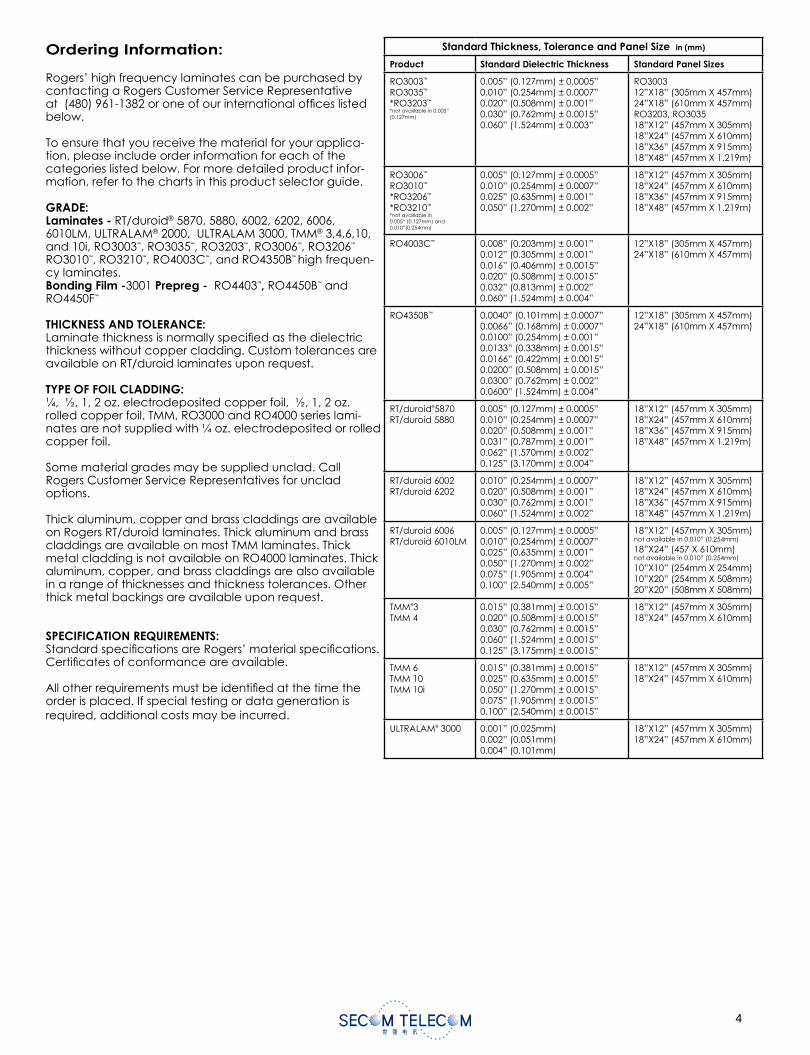
Ordering Information:
Rogers’ high frequency laminates can be purchased by contacting a Rogers Customer Service Representative at (480) 961-1382 or one of our international offi ces listed below.
To ensure that you receive the material for your applica-tion, please include order information for each of the categories listed below. For more detailed product infor-mation, refer to the charts in this product selector guide.
GRADE:Laminates - RT/duroid® 5870, 5880, 6002, 6202, 6006, 6010LM, ULTRALAM® 2000, ULTRALAM 3000, TMM® 3,4,6,10, and 10i, RO3003™, RO3035™, RO3203™, RO3006™, RO3206™
RO3010™, RO3210™, RO4003C™, and RO4350B™ high frequen-cy laminates. Bonding Film -3001 Prepreg - RO4403™, RO4450B™ and RO4450F™
THICKNESS AND TOLERANCE:Laminate thickness is normally specifi ed as the dielectric thickness without copper cladding. Custom tolerances are available on RT/duroid laminates upon request.
TYPE OF FOIL CLADDING:¼, ½, 1, 2 oz. electrodeposited copper foil, ½, 1, 2 oz. rolled copper foil. TMM, RO3000 and RO4000 series lami-nates are not supplied with ¼ oz. electrodeposited or rolled copper foil.
Some material grades may be supplied unclad. Call Rogers Customer Service Representatives for unclad options.
Thick aluminum, copper and brass claddings are available on Rogers RT/duroid laminates. Thick aluminum and brass claddings are available on most TMM laminates. Thick metal cladding is not available on RO4000 laminates. Thick aluminum, copper, and brass claddings are also available in a range of thicknesses and thickness tolerances. Other thick metal backings are available upon request.
SPECIFICATION REQUIREMENTS: Standard specifi cations are Rogers’ material specifi cations. Certifi cates of conformance are available.
All other requirements must be identifi ed at the time the order is placed. If special testing or data generation is required, additional costs may be incurred.
CONTACT INFORMATION:USA: Rogers Advanced Circuit Materials, ISO 9002 certifi ed Tel: 480-961-1382 Fax: 480-961-4533Belgium: Rogers BVBA - Gent Tel: 32-9-2353611 Fax: 32-9-2353658Japan: Rogers Japan Inc. Tel: 81-3-5200-2700 Fax: 81-3-5200-0571Taiwan: Rogers Taiwan Inc. Tel: 886-2-86609056 Fax: 886-2-86609057Korea: Rogers Korea Inc. Tel: 82-31-716-6112 Fax: 82-31-716-6208Singapore: Rogers Technologies Singapore Inc. Tel: 65-747-3521 Fax: 65-747-7425China: Rogers (Shanghai) International Trading Co., Ltd Tel: 86-21-62175599 Fax: 86-21-62677913
The information contained in this product selector guide is intended to assist you in designing with Rogers’ laminates. It is not intended to and does not create any warranties, express or implied, including any warranty of merchantability or fi tness for a particular purpose. The user should determine the suitability of Rogers’ circuit materials for each application.
These commodities, technology and software are exported from the United States in accordance with the Export Administration regulations.Diversion contrary to U.S. law prohibited.
RT/duroid, ULTRALAM, TMM, RO3000, and RO4000 are licensed trademarks of Rogers Corporation.The world runs better with Rogers. and the Rogers’ logo are licensed trademarks of Rogers Corporation.
© 1987, 1991, 1994, 1995, 1999, 2001, 2002, 2004, 2005, 2007, 2008, 2009 All Rights Reserved. Printed in USA. Revised 04/2009 0863-0409-10.0ON Publication #92-601
Standard Thickness, Tolerance and Panel Size in (mm)
Product Standard Dielectric Thickness Standard Panel Sizes
RO3003™
RO3035™
*RO3203™
*not availlable in 0.005” (0.127mm)
0.005” (0.127mm) ± 0.0005”0.010” (0.254mm) ± 0.0007”0.020” (0.508mm) ± 0.001”0.030” (0.762mm) ± 0.0015”0.060” (1.524mm) ± 0.003”
RO300312”X18” (305mm X 457mm)24”X18” (610mm X 457mm)RO3203, RO303518”X12” (457mm X 305mm)18”X24” (457mm X 610mm)18”X36” (457mm X 915mm)18”X48” (457mm X 1.219m)
RO3006™
RO3010™
*RO3206™
*RO3210™
*not availlable in 0.005” (0.127mm) and 0.010”(0.254mm)
0.005” (0.127mm) ± 0.0005”0.010” (0.254mm) ± 0.0007”0.025” (0.635mm) ± 0.001”0.050” (1.270mm) ± 0.002”
18”X12” (457mm X 305mm)18”X24” (457mm X 610mm)18”X36” (457mm X 915mm)18”X48” (457mm X 1.219m)
RO4003C™ 0.008” (0.203mm) ± 0.001”0.012” (0.305mm) ± 0.001”0.016” (0.406mm) ± 0.0015”0.020” (0.508mm) ± 0.0015”0.032” (0.813mm) ± 0.002”0.060” (1.524mm) ± 0.004”
12”X18” (305mm X 457mm)24”X18” (610mm X 457mm)
RO4350B™ 0.0040” (0.101mm) ± 0.0007”0.0066” (0.168mm) ± 0.0007”0.0100” (0.254mm) ± 0.001”0.0133” (0.338mm) ± 0.0015”0.0166” (0.422mm) ± 0.0015”0.0200” (0.508mm) ± 0.0015”0.0300” (0.762mm) ± 0.002”0.0600” (1.524mm) ± 0.004”
12”X18” (305mm X 457mm)24”X18” (610mm X 457mm)
RT/duroid®5870RT/duroid 5880
0.005” (0.127mm) ± 0.0005”0.010” (0.254mm) ± 0.0007”0.020” (0.508mm) ± 0.001”0.031” (0.787mm) ± 0.001”0.062” (1.570mm) ± 0.002”0.125” (3.170mm) ± 0.004”
18”X12” (457mm X 305mm)18”X24” (457mm X 610mm)18”X36” (457mm X 915mm)18”X48” (457mm X 1.219m)
RT/duroid 6002RT/duroid 6202
0.010” (0.254mm) ± 0.0007”0.020” (0.508mm) ± 0.001”0.030” (0.762mm) ± 0.001”0.060” (1.524mm) ± 0.002”
18”X12” (457mm X 305mm)18”X24” (457mm X 610mm)18”X36” (457mm X 915mm)18”X48” (457mm X 1.219m)
RT/duroid 6006RT/duroid 6010LM
0.005” (0.127mm) ± 0.0005”0.010” (0.254mm) ± 0.0007”0.025” (0.635mm) ± 0.001”0.050” (1.270mm) ± 0.002”0.075” (1.905mm) ± 0.004”0.100” (2.540mm) ± 0.005”
18”X12” (457mm X 305mm)not available in 0.010” (0.254mm)
18”X24” (457 X 610mm) not available in 0.010” (0.254mm)
10”X10” (254mm X 254mm)10”X20” (254mm X 508mm)20”X20” (508mm X 508mm)
TMM®3TMM 4
0.015” (0.381mm) ± 0.0015”0.020” (0.508mm) ± 0.0015”0.030” (0.762mm) ± 0.0015”0.060” (1.524mm) ± 0.0015”0.125” (3.175mm) ± 0.0015”
18”X12” (457mm X 305mm)18”X24” (457mm X 610mm)
TMM 6TMM 10TMM 10i
0.015” (0.381mm) ± 0.0015”0.025” (0.635mm) ± 0.0015”0.050” (1.270mm) ± 0.0015”0.075” (1.905mm) ± 0.0015”0.100” (2.540mm) ± 0.0015”
18”X12” (457mm X 305mm)18”X24” (457mm X 610mm)
ULTRALAM® 3000 0.001” (0.025mm)0.002” (0.051mm)0.004” (0.101mm)
18”X12” (457mm X 305mm)18”X24” (457mm X 610mm)
High Frequency Laminates Product Selector Guide
Advanced Circuit Materials
www.rogerscorp.com/acm
The world runs better with Rogers.®
Other thicknesses and panel sizes may be available. Contact customer service for more information.
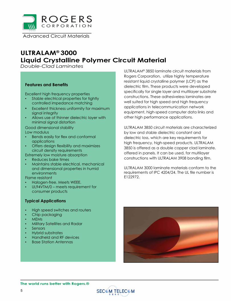
Features and Benefi ts
Excellent high frequency properties• Stable electrical properties for tightly
controlled impedance matching• Excellent thickness uniformity for maximum
signal integrity• Allows use of thinner dielectric layer with
minimal signal distortionGood dimensional stabilityLow modulus• Bends easily for fl ex and conformal
applications• Offers design fl exibility and maximizes
circuit density requirementsExtremely low moisture absorption• Reduces bake times• Maintains stable electrical, mechanical
and dimensional properties in humid environments
Flame resistant• Halogen-free. Meets WEEE.• UL94VTM/0 – meets requirement for
consumer products
Typical Applications
• High speed switches and routers• Chip packaging• MEMs• Military Satellites and Radar• Sensors• Hybrid substrates• Handheld and RF devices• Base Station Antennas
Data SheetRF1.3000
The world runs better with Rogers.®
Advanced Circuit Materials
Advanced Circuit Materials Division100 S. Roosevelt Avenue
Chandler, AZ 85226Tel: 480-961-1382, Fax: 480-961-4533
www.rogerscorporation.com
ULTRALAM® 3850 laminate circuit materials from Rogers Corporation, utilize highly temperature resistant liquid crystalline polymer (LCP) as the dielectric fi lm. These products were developed specifi cally for single layer and multilayer substrate constructions. These adhesiveless laminates are well suited for high speed and high frequency applications in telecommunication network equipment, high-speed computer data links and other high performance applications.
ULTRALAM 3850 circuit materials are characterized by low and stable dielectric constant and dielectric loss, which are key requirements for high frequency, high-speed products. ULTRALAM 3850 is offered as a double copper clad laminate.offered in panels. It can be used, for multilayer constructions with ULTRALAM 3908 bonding fi lm.
ULTRALAM 3000 laminate materials conform to the requirements of IPC 4204/24. The UL fi le number is E122972.
ULTRALAM® 3000Liquid Crystalline Polymer Circuit MaterialDouble-Clad Laminates
Data obtained from cast all polyimide and high Tg FR-4 laminate materials.
The information contained in this datasheet is intended to assist you in designing with Rogers’ liquid crystalline polymer circuit materi-als. It is not intended to and does not create any warranties, express or implied, including any warranty of merchantability or fi tness for a particular purpose or that the results shown on this datasheet will be achieved by a user for a particular purpose. The user is respon-sible for determining the suitability of Rogers’ liquid crystalline polymer circuit materials for each application.
Dielectric Constant Variation: LCP, All Polyimide, and FR-4 laminates
2.5
2.8
3.0
3.3
3.5
3.8
4.0
4.3
4.5
4.8
0 2 4 6 8 10 12
Frequency, GHz
Die
lect
ric
Con
stan
t
FR-4: 50CImmersionFR-4: 23C, 50%RH
PI: 50C Immersion
PI: 23C, 50%RH
LCP: 50C Immersion
LCP: 23C, 50%RH
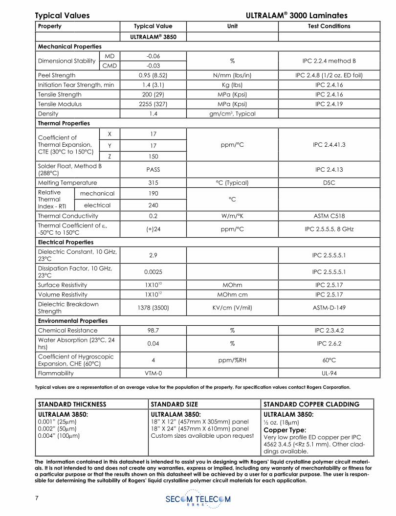
Typical Values ULTRALAM® 3000 LaminatesProperty Typical Value Unit Test Conditions
ULTRALAM® 3850
Mechanical Properties
Dimensional StabilityMD -0.06
% IPC 2.2.4 method BCMD -0.03
Peel Strength 0.95 (8.52) N/mm (lbs/in) IPC 2.4.8 (1/2 oz. ED foil)
Initiation Tear Strength, min 1.4 (3.1) Kg (lbs) IPC 2.4.16
Tensile Strength 200 (29) MPa (Kpsi) IPC 2.4.16
Tensile Modulus 2255 (327) MPa (Kpsi) IPC 2.4.19
Density 1.4 gm/cm3, Typical
Thermal Properties
Coeffi cient of Thermal Expansion, CTE (30°C to 150°C)
X 17
ppm/°C IPC 2.4.41.3Y 17
Z 150
Solder Float, Method B (288°C)
PASS IPC 2.4.13
Melting Temperature 315 °C (Typical) DSC
RelativeThermalIndex - RTI
mechanical 190°C
electrical 240
Thermal Conductivity 0.2 W/m/°K ASTM C518
Thermal Coeffi cient of r,-50°C to 150°C
(+)24 ppm/°C IPC 2.5.5.5, 8 GHz
Electrical Properties
Dielectric Constant, 10 GHz, 23°C
2.9 IPC 2.5.5.5.1
Dissipation Factor, 10 GHz, 23°C
0.0025 IPC 2.5.5.5.1
Surface Resistivity 1X10¹⁰ MOhm IPC 2.5.17
Volume Resistivity 1X10¹² MOhm cm IPC 2.5.17
Dielectric Breakdown Strength
1378 (3500) KV/cm (V/mil) ASTM-D-149
Environmental Properties
Chemical Resistance 98.7 % IPC 2.3.4.2
Water Absorption (23°C, 24 hrs)
0.04 % IPC 2.6.2
Coeffi cient of Hygroscopic Expansion, CHE (60°C)
4 ppm/%RH 60°C
Flammability VTM-0 UL-94
STANDARD THICKNESS STANDARD SIZE STANDARD COPPER CLADDING
ULTRALAM 3850:0.001” (25 m)0.002” (50 m)0.004” (100 m)
ULTRALAM 3850:18” X 12” (457mm X 305mm) panel18” X 24” (457mm X 610mm) panelCustom sizes available upon request
ULTRALAM 3850:½ oz. (18 m)Copper Type: Very low profi le ED copper per IPC 4562 3.4.5 (<Rz 5.1 mm). Other clad-dings available.
The information contained in this datasheet is intended to assist you in designing with Rogers’ liquid crystalline polymer circuit materi-als. It is not intended to and does not create any warranties, express or implied, including any warranty of merchantability or fi tness for a particular purpose or that the results shown on this datasheet will be achieved by a user for a particular purpose. The user is respon-sible for determining the suitability of Rogers’ liquid crystalline polymer circuit materials for each application.
Typical values are a representation of an average value for the population of the property. For specifi cation values contact Rogers Corporation.
The information contained in this datasheet is intended to assist you in designing with Rogers’ liquid crystalline polymer circuit materi-als. It is not intended to and does not create any warranties, express or implied, including any warranty of merchantability or fi tness for a particular purpose or that the results shown on this datasheet will be achieved by a user for a particular purpose. The user is respon-sible for determining the suitability of Rogers’ liquid crystalline polymer circuit materials for each application.
These commodities, technology and software are exported from the United States in accordance with the Export Administration regu-lations. Diversion contrary to U.S. law prohibited.
ULTRALAM, R/fl ex CRYSTAL and RO4450B are licensed trademarks of Rogers CorporationSPEEDBOARD is a registered trademark of W.L. Gore & Associates, Inc.
©2003, 2004, 2005, 2006, 2007, 2008 Rogers Corporation, Printed in U.S.A, All rights reserved. Revised 03/08 0788-0308-0.3-CC, Publication #92-125
CONTACT INFORMATION:
USA: Rogers Advanced Circuit Materials, ISO 9002 Certifi ed Tel: 480-961-1382 Fax: 480-961-4533Belgium: Rogers NV - Gent Tel: +32-9-2353611 Fax: +32-9-2353658Japan: Rogers Japan Inc. Tel: 81-3-5200-2700 Fax: 81-3-5200-0571Taiwan: Rogers Taiwan Inc. Tel: 886-2-86609056 Fax: 886-2-86609057Korea: Rogers Korea Inc. Tel: 82-31-716-6112 Fax: 82-31-716-6208Singapore: Rogers Technologies Singapore Inc. Tel: 65-747-3521 Fax: 65-747-7425China: Rogers (Shanghai) International Trading Co., Ltd Tel: 86-21-63916088 Fax: 86-21-63915060
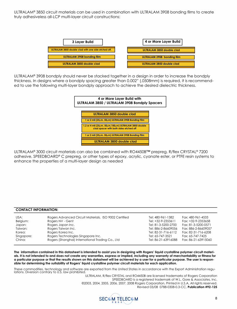
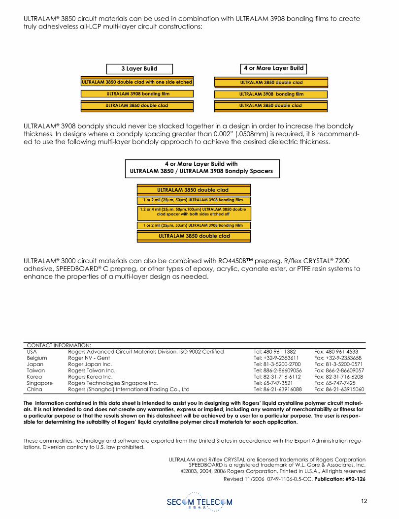
ULTRALAM® 3850 circuit materials can be used in combination with ULTRALAM 3908 bonding fi lms to create truly adhesiveless all-LCP multi-layer circuit constructions:
ULTRALAM 3850 double clad with one side etched off.
ULTRALAM 3908 bonding fi lm
3 Layer Build
ULTRALAM 3850 double clad
ULTRALAM 3850 double clad
4 or More Layer Build
ULTRALAM 3908 bonding fi lm
ULTRALAM 3850 double clad
ULTRALAM® 3908 bondply should never be stacked together in a design in order to increase the bondply thickness. In designs where a bondply spacing greater than 0.002” (.0508mm) is required, it is recommend-ed to use the following multi-layer bondply approach to achieve the desired dielectric thickness.
1 or 2 mil (25μm, 50μm) ULTRALAM 3908 Bonding Film
4 or More Layer Build with ULTRALAM 3850 / ULTRALAM 3908 Bondply Spacers
ULTRALAM 3850 double clad
ULTRALAM 3850 double clad
1,2 or 4 mil (25μm, 50μm,100μm) ULTRALAM 3850 double clad spacer with both sides etched off
1 or 2 mil (25μm, 50μm) ULTRALAM 3908 Bonding Film
ULTRALAM® 3000 circuit materials can also be combined with RO4450B™ prepreg, R/fl ex CRYSTAL® 7200 adhesive, SPEEDBOARD® C prepreg, or other types of epoxy, acrylic, cyanate ester, or PTFE resin systems to enhance the properties of a multi-layer design as needed
Features and Bene ts
Excellent electrical properties• Stable dielectric constant for minimal
cross talk between signal layers• Allows use of thinner bonding lm with
very minimal signal lossesLow modulus• Bends easily for ex applications• Offers design flexibility and minimizes
space requirementsExtremely low moisture absorption• Maintains stable electrical, mechanical
and dimensional propertiesFlame resistant• Halogen-free• UL94VTM/0 – meets requirement for con-
sumer products
Typical Applications
All LCP ex interconnections• High speed switches and routers• Backplane-to-backplane• Data links• Card-to-cardHybrid substrates• Handheld and RF devices
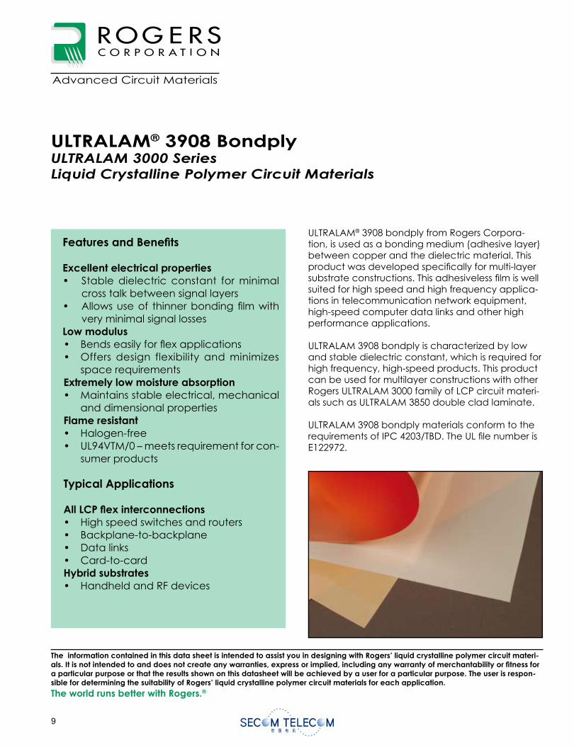
ULTRALAM® 3908 bondply from Rogers Corpora-tion, is used as a bonding medium (adhesive layer) between copper and the dielectric material. This product was developed speci cally for multi-layer substrate constructions. This adhesiveless lm is well suited for high speed and high frequency applica-tions in telecommunication network equipment, high-speed computer data links and other high performance applications.
ULTRALAM 3908 bondply is characterized by low and stable dielectric constant, which is required for high frequency, high-speed products. This product can be used for multilayer constructions with other Rogers ULTRALAM 3000 family of LCP circuit materi-als such as ULTRALAM 3850 double clad laminate.
ULTRALAM 3908 bondply materials conform to the requirements of IPC 4203/TBD. The UL le number is E122972.
ULTRALAM® 3908 BondplyULTRALAM 3000 Series Liquid Crystalline Polymer Circuit Materials
The world runs better with Rogers.®
Data SheetRF1.3908
Advanced Circuit Materials
Advanced Circuit Materials Division100 N. Dobson RoadChandler, AZ 85224
Tel: 480-961-1382, Fax: 480-961-4533www.rogerscorporation.com
The information contained in this data sheet is intended to assist you in designing with Rogers’ liquid crystalline polymer circuit materi-als. It is not intended to and does not create any warranties, express or implied, including any warranty of merchantability or tness for a particular purpose or that the results shown on this datasheet will be achieved by a user for a particular purpose. The user is respon-sible for determining the suitability of Rogers’ liquid crystalline polymer circuit materials for each application.
0
Features and Bene ts
Excellent electrical properties• Stable dielectric constant for minimal
cross talk between signal layers• Allows use of thinner bonding lm with
very minimal signal lossesLow modulus• Bends easily for ex applications• Offers design flexibility and minimizes
space requirementsExtremely low moisture absorption• Maintains stable electrical, mechanical
and dimensional propertiesFlame resistant• Halogen-free• UL94VTM/0 – meets requirement for con-
sumer products
Typical Applications
All LCP ex interconnections• High speed switches and routers• Backplane-to-backplane• Data links• Card-to-cardHybrid substrates• Handheld and RF devices
ULTRALAM® 3908 bondply from Rogers Corpora-tion, is used as a bonding medium (adhesive layer) between copper and the dielectric material. This product was developed speci cally for multi-layer substrate constructions. This adhesiveless lm is well suited for high speed and high frequency applica-tions in telecommunication network equipment, high-speed computer data links and other high performance applications.
ULTRALAM 3908 bondply is characterized by low and stable dielectric constant, which is required for high frequency, high-speed products. This product can be used for multilayer constructions with other Rogers ULTRALAM 3000 family of LCP circuit materi-als such as ULTRALAM 3850 double clad laminate.
ULTRALAM 3908 bondply materials conform to the requirements of IPC 4203/TBD. The UL le number is E122972.
ULTRALAM® 3908 BondplyULTRALAM 3000 Series Liquid Crystalline Polymer Circuit Materials
The world runs better with Rogers.®
Data SheetRF1.3908
Advanced Circuit Materials
Advanced Circuit Materials Division100 N. Dobson RoadChandler, AZ 85224
Tel: 480-961-1382, Fax: 480-961-4533www.rogerscorporation.com
The information contained in this data sheet is intended to assist you in designing with Rogers’ liquid crystalline polymer circuit materi-als. It is not intended to and does not create any warranties, express or implied, including any warranty of merchantability or tness for a particular purpose or that the results shown on this datasheet will be achieved by a user for a particular purpose. The user is respon-sible for determining the suitability of Rogers’ liquid crystalline polymer circuit materials for each application.
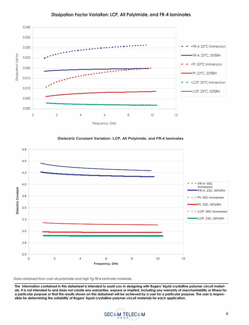
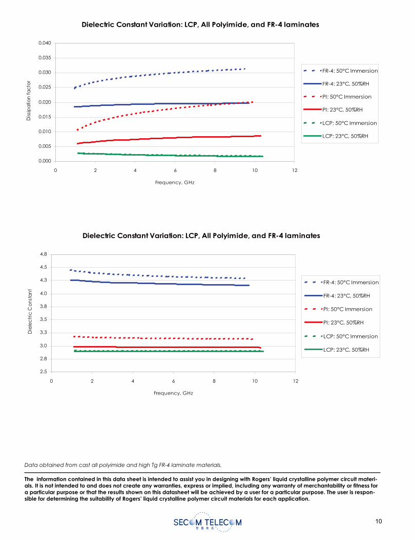
Data obtained from cast all polyimide and high Tg FR-4 laminate materials.
Dielectric Constant Variation: LCP, All Polyimide, and FR-4 laminates
0.000
0.005
0.010
0.015
0.020
0.025
0.030
0.035
0.040
0 2 4 6 8 10 12
Frequency, GHz
Dis
sip
atio
nfa
cto
r
FR-4: 50°C Immersion
FR-4: 23°C, 50%RH
PI: 50°C Immersion
PI: 23°C, 50%RH
LCP: 50°C Immersion
LCP: 23°C, 50%RH
Dielectric Constant Variation: LCP, All Polyimide, and FR-4 laminates
2.5
2.8
3.0
3.3
3.5
3.8
4.0
4.3
4.5
4.8
0 2 4 6 8 10 12
Frequency, GHz
Die
lec
tric
Co
nst
an
t
FR-4: 50°C Immersion
FR-4: 23°C, 50%RH
PI: 50°C Immersion
PI: 23°C, 50%RH
LCP: 50°C Immersion
LCP: 23°C, 50%RH
The information contained in this data sheet is intended to assist you in designing with Rogers’ liquid crystalline polymer circuit materi-als. It is not intended to and does not create any warranties, express or implied, including any warranty of merchantability or tness for a particular purpose or that the results shown on this datasheet will be achieved by a user for a particular purpose. The user is respon-sible for determining the suitability of Rogers’ liquid crystalline polymer circuit materials for each application.
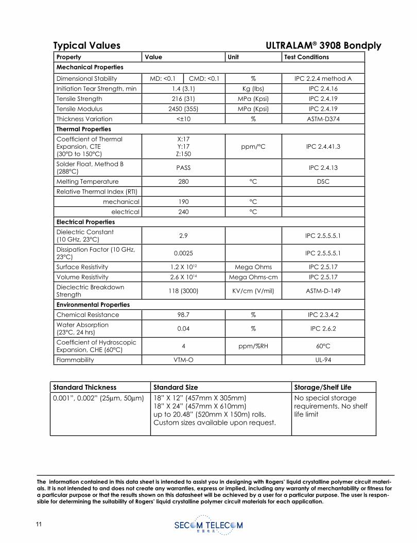
Typical Values ULTRALAM® 3908 BondplyProperty Value Unit Test Conditions
Mechanical Properties
Dimensional Stability MD: <0.1 CMD: <0.1 % IPC 2.2.4 method A
Initiation Tear Strength, min 1.4 (3.1) Kg (lbs) IPC 2.4.16
Tensile Strength 216 (31) MPa (Kpsi) IPC 2.4.19
Tensile Modulus 2450 (355) MPa (Kpsi) IPC 2.4.19
Thickness Variation <±10 % ASTM-D374
Thermal Properties
Coef cient of Thermal Expansion, CTE(30°D to 150°C)
X:17Y:17Z:150
ppm/°C IPC 2.4.41.3
Solder Float, Method B (288°C)
PASS IPC 2.4.13
Melting Temperature 280 °C DSC
Relative Thermal Index (RTI)
mechanical 190 °C
electrical 240 °C
Electrical Properties
Dielectric Constant (10 GHz, 23°C)
2.9 IPC 2.5.5.5.1
Dissipation Factor (10 GHz, 23°C)
0.0025 IPC 2.5.5.5.1
Surface Resistivity 1.2 X 10¹² Mega Ohms IPC 2.5.17
Volume Resistivity 2.6 X 10¹⁴ Mega Ohms-cm IPC 2.5.17
Dieclectric Breakdown Strength
118 (3000) KV/cm (V/mil) ASTM-D-149
Environmental Properties
Chemical Resistance 98.7 % IPC 2.3.4.2
Water Absorption (23°C, 24 hrs)
0.04 % IPC 2.6.2
Coef cient of Hydroscopic Expansion, CHE (60°C)
4 ppm/%RH 60°C
Flammability VTM-O UL-94
Standard Thickness Standard Size Storage/Shelf Life
0.001”, 0.002” (25µm, 50µm) 18” X 12” (457mm X 305mm)18” X 24” (457mm X 610mm)up to 20.48” (520mm X 150m) rolls.Custom sizes available upon request.
No special storage requirements. No shelf life limit
The information contained in this data sheet is intended to assist you in designing with Rogers’ liquid crystalline polymer circuit materi-als. It is not intended to and does not create any warranties, express or implied, including any warranty of merchantability or tness for a particular purpose or that the results shown on this datasheet will be achieved by a user for a particular purpose. The user is respon-sible for determining the suitability of Rogers’ liquid crystalline polymer circuit materials for each application.
CONTACT INFORMATION:USA Rogers Advanced Circuit Materials Division, ISO 9002 Certi ed Tel: 480 961-1382 Fax: 480 961-4533Belgium Roger NV - Gent Tel: +32-9-2353611 Fax: +32-9-2353658Japan Roger Japan Inc. Tel: 81-3-5200-2700 Fax: 81-3-5200-0571Taiwan Rogers Taiwan Inc. Tel: 886-2-86609056 Fax: 866-2-86609057Korea Rogers Korea Inc. Tel: 82-31-716-6112 Fax: 82-31-716-6208Singapore Rogers Technologies Singapore Inc. Tel: 65-747-3521 Fax: 65-747-7425China Rogers (Shanghai) International Trading Co., Ltd Tel: 86-21-63916088 Fax: 86-21-63915060
The information contained in this data sheet is intended to assist you in designing with Rogers’ liquid crystalline polymer circuit materi-als. It is not intended to and does not create any warranties, express or implied, including any warranty of merchantability or tness for a particular purpose or that the results shown on this datasheet will be achieved by a user for a particular purpose. The user is respon-sible for determining the suitability of Rogers’ liquid crystalline polymer circuit materials for each application.
These commodities, technology and software are exported from the United States in accordance with the Export Administration regu-lations. Diversion contrary to U.S. law prohibited.
ULTRALAM and R/ ex CRYSTAL are licensed trademarks of Rogers CorporationSPEEDBOARD is a registered trademark of W.L. Gore & Associates, Inc.
©2003, 2004, 2006 Rogers Corporation, Printed in U.S.A., All rights reserved
Revised 11/2006 0749-1106-0.5-CC, Publication: #92-126
ULTRALAM® 3850 circuit materials can be used in combination with ULTRALAM 3908 bonding lms to create truly adhesiveless all-LCP multi-layer circuit constructions:
ULTRALAM 3850 double clad with one side etched
ULTRALAM 3908 bonding lm
3 Layer Build
ULTRALAM 3850 double clad
ULTRALAM 3850 double clad
4 or More Layer Build
ULTRALAM 3908 bonding lm
ULTRALAM 3850 double clad
ULTRALAM® 3908 bondply should never be stacked together in a design in order to increase the bondply thickness. In designs where a bondply spacing greater than 0.002” (.0508mm) is required, it is recommend-ed to use the following multi-layer bondply approach to achieve the desired dielectric thickness.
1 or 2 mil (25µm, 50µm) ULTRALAM 3908 Bonding Film
4 or More Layer Build with ULTRALAM 3850 / ULTRALAM 3908 Bondply Spacers
ULTRALAM 3850 double clad
ULTRALAM 3850 double clad
1,2 or 4 mil (25µm, 50µm,100µm) ULTRALAM 3850 double clad spacer with both sides etched off
1 or 2 mil (25µm, 50µm) ULTRALAM 3908 Bonding Film
ULTRALAM® 3000 circuit materials can also be combined with RO4450B™ prepreg, R/ ex CRYSTAL® 7200 adhesive, SPEEDBOARD® C prepreg, or other types of epoxy, acrylic, cyanate ester, or PTFE resin systems to enhance the properties of a multi-layer design as needed.
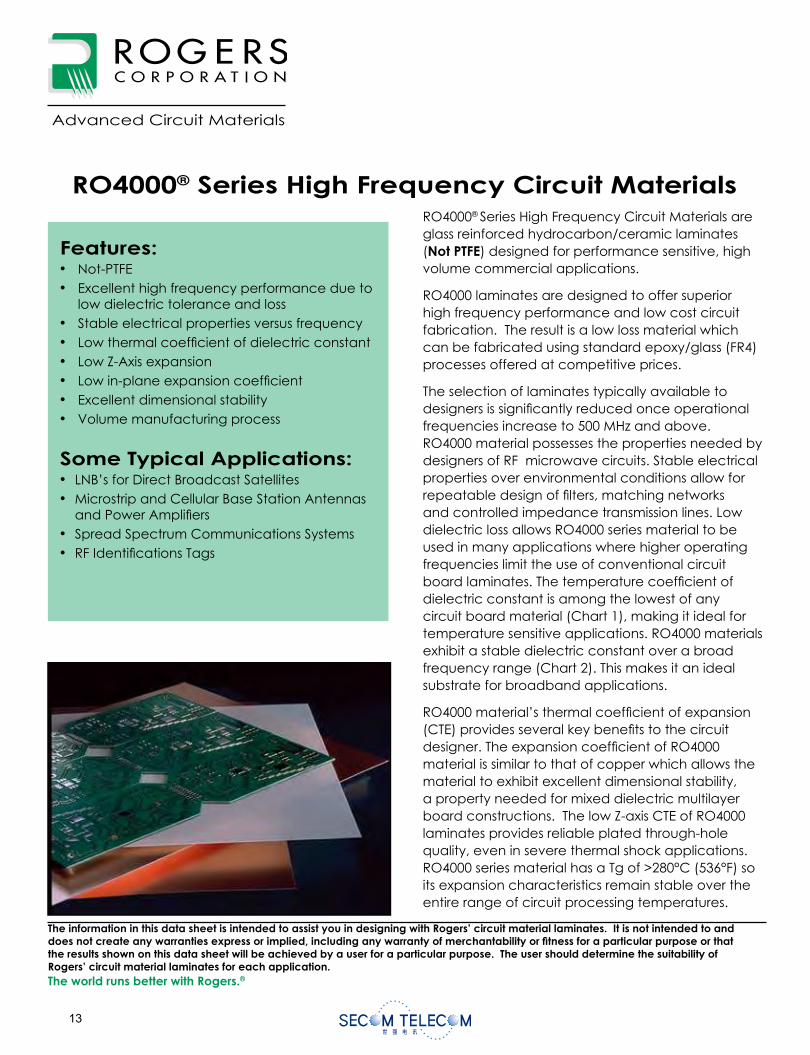
RO4000® Series High Frequency Circuit Materials are glass reinforced hydrocarbon/ceramic laminates(Not PTFE) designed for performance sensitive, high volume commercial applications.
RO4000 laminates are designed to offer superior high frequency performance and low cost circuit fabrication. The result is a low loss material which can be fabricated using standard epoxy/glass (FR4) processes offered at competitive prices.
The selection of laminates typically available to designers is signi cantly reduced once operational frequencies increase to 500 MHz and above. RO4000 material possesses the properties needed by designers of RF microwave circuits. Stable electrical properties over environmental conditions allow for repeatable design of lters, matching networks and controlled impedance transmission lines. Low dielectric loss allows RO4000 series material to be used in many applications where higher operating frequencies limit the use of conventional circuit board laminates. The temperature coef cient of dielectric constant is among the lowest of any circuit board material (Chart 1), making it ideal for temperature sensitive applications. RO4000 materials exhibit a stable dielectric constant over a broad frequency range (Chart 2). This makes it an ideal substrate for broadband applications.
RO4000 material’s thermal coef cient of expansion (CTE) provides several key bene ts to the circuit designer. The expansion coef cient of RO4000 material is similar to that of copper which allows the material to exhibit excellent dimensional stability, a property needed for mixed dielectric multilayer board constructions. The low Z-axis CTE of RO4000 laminates provides reliable plated through-hole quality, even in severe thermal shock applications. RO4000 series material has a Tg of >280°C (536°F) so its expansion characteristics remain stable over the entire range of circuit processing temperatures.
RO4000® Series High Frequency Circuit Materials
Features:• Not-PTFE• Excellent high frequency performance due to
low dielectric tolerance and loss• Stable electrical properties versus frequency• Low thermal coef cient of dielectric constant• Low Z-Axis expansion• Low in-plane expansion coef cient• Excellent dimensional stability• Volume manufacturing process
Some Typical Applications:• LNB’s for Direct Broadcast Satellites• Microstrip and Cellular Base Station Antennas
and Power Ampli ers• Spread Spectrum Communications Systems• RF Identi cations Tags
The world runs better with Rogers.®
Advanced Circuit Materials
The information in this data sheet is intended to assist you in designing with Rogers’ circuit material laminates. It is not intended to and does not create any warranties express or implied, including any warranty of merchantability or tness for a particular purpose or that the results shown on this data sheet will be achieved by a user for a particular purpose. The user should determine the suitability of Rogers’ circuit material laminates for each application.
0.000
-0.200
-0.400
-0.600
-0.800
-1.000
-1.200
-1.400
-1.600 0 2 4 6 8 10 12 14 16 18
dB/In
ch
F requency, GHz
RO3003 PTFE Woven Glass RO4003 RO4350 BT Glass BT/Epoxy FR4Epoxy/PPO
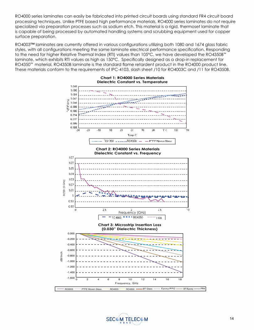
Chart 1: RO4000 Series MaterialsDielectric Constant vs. Temperature
Chart 2: RO4000 Series MaterialsDielectric Constant vs. Frequency
Chart 3: Microstrip Insertion Loss(0.030” Dielectric Thickness)
RO4000 series laminates can easily be fabricated into printed circuit boards using standard FR4 circuit board processing techniques. Unlike PTFE based high performance materials, RO4000 series laminates do not require specialized via preparation processes such as sodium etch. This material is a rigid, thermoset laminate that is capable of being processed by automated handling systems and scrubbing equipment used for copper surface preparation.
RO4003™ laminates are currently offered in various con gurations utilizing both 1080 and 1674 glass fabric styles, with all con gurations meeting the same laminate electrical performance speci cation. Responding to the need for higher Relative Thermal Index (RTI) values than 105°C, we have developed the RO4350B™
laminate, which exhibits RTI values as high as 150°C. Speci cally designed as a drop-in replacement for RO4350™ material, RO4350B laminate is the standard ame retardent product in the RO4000 product line. These materials conform to the requirements of IPC-4103, slash sheet /10 for RO4003C and /11 for RO4350B.
Er(f
)Er (
5 G
Hz)
Frequency (GHz)
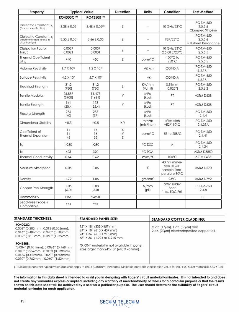
STANDARD THICKNESS: STANDARD PANEL SIZE:
12” X 18” (305 X457 mm)24” X 18” (610 X 457 mm)24” X 36” (610 X 915 mm)48” X 36” (1.224 m X 915 mm)
*0. 004” material in not available in panel sizes larger than 24”x18” (610 X 457mm).
STANDARD COPPER CLADDING:
½ oz. (17 m), 1 oz. (35 m) and2 oz. (70 m) electrodeposited copper foil.
RO4003C:0.008” (0.203mm), 0.012 (0.305mm), 0.016” (0.406mm), 0.020” (0.508mm)0.032” (0.813mm), 0.060” (1.524mm)
RO4350B:*0.004” (0.101mm), 0.0066” (0.168mm)0.010” (0.254mm), 0.0133 (0.338mm), 0.0166 (0.422mm), 0.020” (0.508mm)0.030” (0.762mm), 0.060” (1.524mm)
(1) Dielectric constant typical value does not apply to 0.004 (0.101mm) laminates. Dielectric constant speci cation value for 0.004 RO4350B material is 3.36 ± 0.05
Property Typical Value Direction Units Condition Test Method
RO4003C™ RO4350B™
Dielectric Constant, r(Process speci cation)
3.38 ± 0.05 3.48 ± 0.05(1) Z -- 10 GHz/23°CIPC-TM-650
2.5.5.5Clamped Stripline
Dielectric Constant, r(Recommended for use in circuit design)
3.55 ± 0.05 3.66 ± 0.05 Z -- FSR/23°CIPC-TM-650
2.5.5.6Full Sheet Resonance
Dissipation Factor tan,
0.00270.0021
0.00370.0031
Z --10 GHz/23°C2.5 GHz/23°C
IPC-TM-6502.5.5.5
Thermal Coef cient of r
+40 +50 Z ppm/°C-100°C to
250°CIPC-TM-650
2.5.5.5
Volume Resistivity 1.7 X 10¹⁰ 1.2 X 10¹⁰ M •cm COND AIPC-TM-650
2.5.17.1
Surface Resistivity 4.2 X 10⁹ 5.7 X 10⁹ M COND AIPC-TM-650
2.5.17.1
Electrical Strength31.2(780)
31.2(780)
ZKV/mm(V/mil)
0.51mm(0.020”)
IPC-TM-6502.5.6.2
Tensile Modulus26,889(3900)
11,473(1664)
YMPa(kpsi)
RT ASTM D638
Tensile Strength141
(20.4)175
(25.4)Y
MPa(kpsi)
RT ASTM D638
Flexural Strength276(40)
255(37)
MPa(kpsi)
IPC-TM-6502.4.4
Dimensional Stability <0.3 <0.5 X,Ymm/m
(mils/inch)after etch+E2/150°C
IPC-TM-6502.4.39A
Coef cient of Thermal Expansion
111446
141635
XYZ
ppm/°C -55 to 288°CIPC-TM-650
2.1.41
Tg >280 >280 °C DSC AIPC-TM-650
2.4.24
Td 425 390 °C TGA ASTM D3850
Thermal Conductivity 0.64 0.62 W/m/°K 100°C ASTM F433
Moisture Absorption 0.06 0.06 %
48 hrs immer-sion 0.060”
sample Tem-perature 50°C
ASTM D570
Density 1.79 1.86 gm/cm3 23°C ASTM D792
Copper Peel Strength1.05(6.0)
0.88(5.0)
N/mm(pli)
after solder oat
1 oz. EDC Foil
IPC-TM-6502.4.8
Flammability N/A 94V-0 UL
Lead-Free Process Compatible
Yes Yes
The information in this data sheet is intended to assist you in designing with Rogers’ circuit material laminates. It is not intended to and does not create any warranties express or implied, including any warranty of merchantability or tness for a particular purpose or that the results shown on this data sheet will be achieved by a user for a particular purpose. The user should determine the suitability of Rogers’ circuit material laminates for each application.
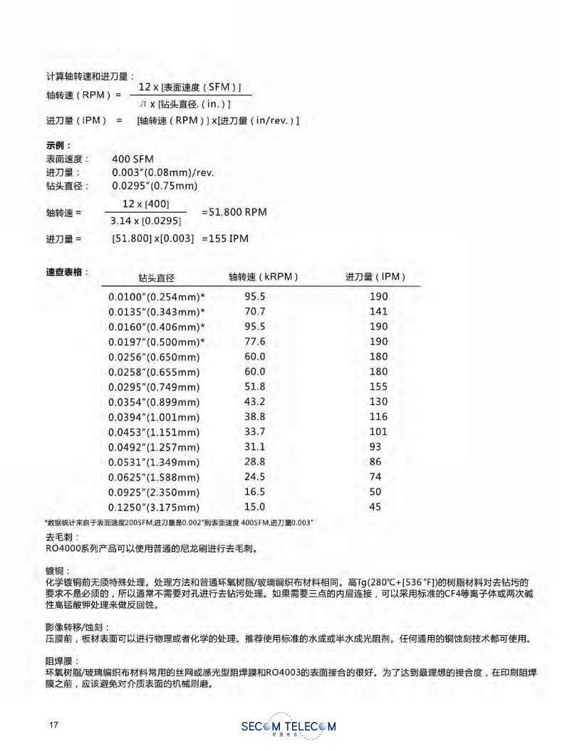
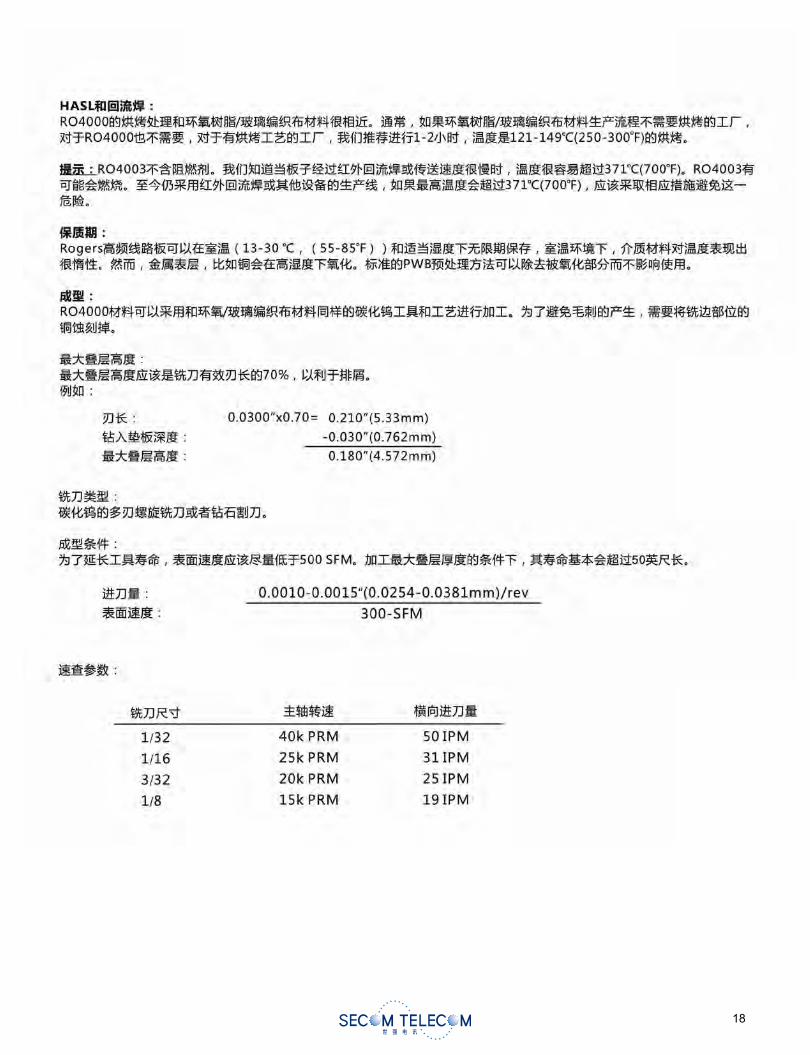
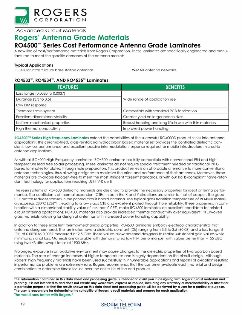
Rogers’ Antenna Grade Materials RO4500™ Series Cost Performance Antenna Grade LaminatesA new line of cost/performance materials from Rogers Corporation. These laminates are speci cally engineered and manu-factured to meet the speci c demands of the antenna markets.
Typical Applications· Cellular infrastructure base station antennas · WiMAX antenna networks
RO4533™, RO4534™, AND RO4535™ Laminates
FEATURES BENEFITSLoss range (0.0020 to 0.0037)
Wide range of application useDk range (3.3 to 3.5)
Low PIM response
Thermoset resin system Compatible with standard PCB fabrication
Excellent dimensional stability Greater yield on larger panels sizes
Uniform mechanical properties Robust handing and long life in use with thin materials
High thermal conductivity Improved power handling
RO4500™ Series High Frequency Laminates extend the capabilities of the successful RO4000® product series into antenna applications. This ceramic- lled, glass-reinforced hydrocarbon based material set provides the controlled dielectric con-stant, low loss performance and excellent passive intermodulation response required for mobile infrastructure microstrip antenna applications.
As with all RO4000 High Frequency Laminates, RO4500 laminates are fully compatible with conventional FR4 and high temperature lead free solder processing. These laminates do not require special treatment needed on traditional PTFE-based laminates for plated through hole preparation. This product series is an affordable alternative to more conventional antenna technologies, thus allowing designers to maximize the price and performance of their antennas. Moreover, these materials are available halogen-free to meet the most stringent “green” standards, or with our RoHS-compliant ame-retar-dant technology for applications requiring UL94 V-0 certi
The resin systems of RO4500 dielectric materials are designed to provide the necessary properties for ideal antenna perfor-mance. The coef cients of thermal expansion (CTEs) in both the X and Y directions are similar to that of copper. The good CTE match reduces stresses in the printed circuit board antenna. The typical glass transition temperature of RO4500 materi-als exceeds 280°C (536°F), leading to a low z-axis CTE and excellent plated through hole reliability. These properties, in com-bination with a dimensional stability value of less than 0.05%, make RO4500 laminates an excellent candidate for printed circuit antenna applications. RO4500 materials also provide increased thermal conductivity over equivalent PTFE/woven glass materials, allowing for design of antennas with increased power handling capability.
In addition to these excellent thermo-mechanical properties, RO4500 laminates embody electrical characteristics that antenna designers need. The laminates have a dielectric constant (Dk) ranging from 3.3 to 3.5 (±0.08) and a loss tangent (Df) of 0.0020 to 0.0037 measured at 2.5 GHz. These values allow antenna designers to realize substantial gain values while minimizing signal loss. Materials are available with demonstrated low PIM performance, with values better than –155 dBC using two 43 dBm swept tones at 1900 MHz.
Prolonged exposure in an oxidative environment may cause changes to the dielectric properties of hydrocarbon based materials. The rate of change increases at higher temperatures and is highly dependent on the circuit design. Although Rogers’ high frequency materials have been used successfully in innumerable applications and reports of oxidation resulting in performance problems are extremely rare, Rogers recommends that the customer evaluate each material and design combination to determine tness for use over the entire life of the end product.
Advanced Circuit Materials
Advanced Circuit Materials Division100 S. Roosevelt Avenue
Chandler, AZ 85224Tel: 480-961-1382, Fax: 480-917-5256
www.rogerscorporation.com
Preliminary Data SheetAntenna Grade Laminates
The information contained in this data sheet and processing guide is intended to assist you in designing with Rogers’ circuit materials and prepreg. It is not intended to and does not create any warranties, express or implied, including any warranty of merchantability or tness for a particular purpose or that the results shown on this data sheet and processing guide will be achieved by a user for a particular purpose. The user is responsible for determining the suitability of Rogers’ circuit materials and prepreg for each application.The world runs better with Rogers.®
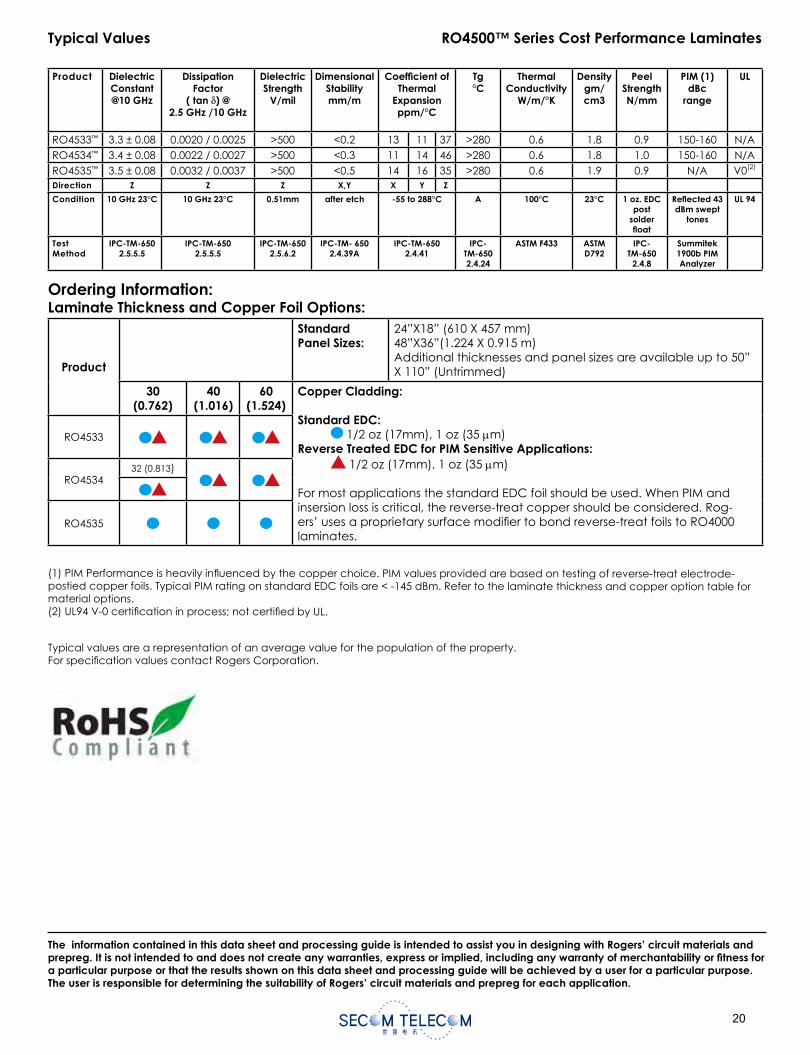
0
Rogers’ Antenna Grade Materials RO4500™ Series Cost Performance Antenna Grade LaminatesA new line of cost/performance materials from Rogers Corporation. These laminates are speci cally engineered and manu-factured to meet the speci c demands of the antenna markets.
Typical Applications· Cellular infrastructure base station antennas · WiMAX antenna networks
RO4533™, RO4534™, AND RO4535™ Laminates
FEATURES BENEFITSLoss range (0.0020 to 0.0037)
Wide range of application useDk range (3.3 to 3.5)
Low PIM response
Thermoset resin system Compatible with standard PCB fabrication
Excellent dimensional stability Greater yield on larger panels sizes
Uniform mechanical properties Robust handing and long life in use with thin materials
High thermal conductivity Improved power handling
RO4500™ Series High Frequency Laminates extend the capabilities of the successful RO4000® product series into antenna applications. This ceramic- lled, glass-reinforced hydrocarbon based material set provides the controlled dielectric con-stant, low loss performance and excellent passive intermodulation response required for mobile infrastructure microstrip antenna applications.
As with all RO4000 High Frequency Laminates, RO4500 laminates are fully compatible with conventional FR4 and high temperature lead free solder processing. These laminates do not require special treatment needed on traditional PTFE-based laminates for plated through hole preparation. This product series is an affordable alternative to more conventional antenna technologies, thus allowing designers to maximize the price and performance of their antennas. Moreover, these materials are available halogen-free to meet the most stringent “green” standards, or with our RoHS-compliant ame-retar-dant technology for applications requiring UL94 V-0 certi
The resin systems of RO4500 dielectric materials are designed to provide the necessary properties for ideal antenna perfor-mance. The coef cients of thermal expansion (CTEs) in both the X and Y directions are similar to that of copper. The good CTE match reduces stresses in the printed circuit board antenna. The typical glass transition temperature of RO4500 materi-als exceeds 280°C (536°F), leading to a low z-axis CTE and excellent plated through hole reliability. These properties, in com-bination with a dimensional stability value of less than 0.05%, make RO4500 laminates an excellent candidate for printed circuit antenna applications. RO4500 materials also provide increased thermal conductivity over equivalent PTFE/woven glass materials, allowing for design of antennas with increased power handling capability.
In addition to these excellent thermo-mechanical properties, RO4500 laminates embody electrical characteristics that antenna designers need. The laminates have a dielectric constant (Dk) ranging from 3.3 to 3.5 (±0.08) and a loss tangent (Df) of 0.0020 to 0.0037 measured at 2.5 GHz. These values allow antenna designers to realize substantial gain values while minimizing signal loss. Materials are available with demonstrated low PIM performance, with values better than –155 dBC using two 43 dBm swept tones at 1900 MHz.
Prolonged exposure in an oxidative environment may cause changes to the dielectric properties of hydrocarbon based materials. The rate of change increases at higher temperatures and is highly dependent on the circuit design. Although Rogers’ high frequency materials have been used successfully in innumerable applications and reports of oxidation resulting in performance problems are extremely rare, Rogers recommends that the customer evaluate each material and design combination to determine tness for use over the entire life of the end product.
Advanced Circuit Materials
Advanced Circuit Materials Division100 S. Roosevelt Avenue
Chandler, AZ 85224Tel: 480-961-1382, Fax: 480-917-5256
www.rogerscorporation.com
Preliminary Data SheetAntenna Grade Laminates
The information contained in this data sheet and processing guide is intended to assist you in designing with Rogers’ circuit materials and prepreg. It is not intended to and does not create any warranties, express or implied, including any warranty of merchantability or tness for a particular purpose or that the results shown on this data sheet and processing guide will be achieved by a user for a particular purpose. The user is responsible for determining the suitability of Rogers’ circuit materials and prepreg for each application.The world runs better with Rogers.®
(1) PIM Performance is heavily in uenced by the copper choice. PIM values provided are based on testing of reverse-treat electrode-postied copper foils. Typical PIM rating on standard EDC foils are < -145 dBm. Refer to the laminate thickness and copper option table for material options.(2) UL94 V-0 certi cation in process; not certi ed by UL.
Typical Values RO4500™ Series Cost Performance Laminates
Typical values are a representation of an average value for the population of the property. For speci cation values contact Rogers Corporation.
The information contained in this data sheet and processing guide is intended to assist you in designing with Rogers’ circuit materials and prepreg. It is not intended to and does not create any warranties, express or implied, including any warranty of merchantability or tness for a particular purpose or that the results shown on this data sheet and processing guide will be achieved by a user for a particular purpose. The user is responsible for determining the suitability of Rogers’ circuit materials and prepreg for each application.
Ordering Information:Laminate Thickness and Copper Foil Options:
Product
StandardPanel Sizes:
24”X18” (610 X 457 mm)48”X36”(1.224 X 0.915 m)Additional thicknesses and panel sizes are available up to 50” X 110” (Untrimmed)
30(0.762)
40(1.016)
60(1.524)
Copper Cladding:
Standard EDC: 1/2 oz (17mm), 1 oz (35 m)
Reverse Treated EDC for PIM Sensitive Applications: 1/2 oz (17mm), 1 oz (35 m)
For most applications the standard EDC foil should be used. When PIM and insersion loss is critical, the reverse-treat copper should be considered. Rog-ers’ uses a proprietary surface modi er to bond reverse-treat foils to RO4000 laminates.
RO4533
RO453432 (0.813)
RO4535
Product DielectricConstant@10 GHz
DissipationFactor
( tan δ) @2.5 GHz /10 GHz
DielectricStrength
V/mil
DimensionalStabilitymm/m
Coef cient of Thermal
Expansionppm/°C
Tg°C
ThermalConductivity
W/m/°K
Densitygm/cm3
PeelStrengthN/mm
PIM (1)dBc
range
UL
RO4533™ 3.3 ± 0.08 0.0020 / 0.0025 >500 <0.2 13 11 37 >280 0.6 1.8 0.9 150-160 N/ARO4534™ 3.4 ± 0.08 0.0022 / 0.0027 >500 <0.3 11 14 46 >280 0.6 1.8 1.0 150-160 N/ARO4535™ 3.5 ± 0.08 0.0032 / 0.0037 >500 <0.5 14 16 35 >280 0.6 1.9 0.9 N/A V0(2)
Direction Z Z Z X,Y X Y Z
Condition 10 GHz 23°C 10 GHz 23°C 0.51mm after etch -55 to 288°C A 100°C 23°C 1 oz. EDC post
solder oat
Re ected 43 dBm swept
tones
UL 94
Test Method
IPC-TM-6502.5.5.5
IPC-TM-6502.5.5.5
IPC-TM-6502.5.6.2
IPC-TM- 6502.4.39A
IPC-TM-6502.4.41
IPC-TM-6502.4.24
ASTM F433 ASTM D792
IPC-TM-650
2.4.8
Summitek1900b PIM Analyzer
RO4730™ LoPro™ Antenna Grade Laminates
Data Sheet1.4730 LoPro Antenna Grade Laminate
Advanced Circuit Materials
Advanced Circuit Materials Division100 S. Roosevelt Avenue
Chandler, AZ 85226Tel: 480-961-1382, Fax: 480-961-4533
www.rogerscorp.com
The world runs better with Rogers.®
Features: Benefi ts:
RO4730™ LoPro™ laminate (low loss dielectric with low pro le foil)
• Reduced PIM• Low insertion loss• Match DK to 3.0 materials
Unique ller / closed microspheres • Low density/lightweight - ~30% lighter than PTFE/ glass
Low Z-Axis CTE ~40 ppm/°CHigh Tg ( same as RO4000® laminate - >280°C)
• Design exibility• Automated assembly compatible
Low TCDk ~23° ppm/°C • Consistent circuit performance
Specially formulated thermoset resin system/ ller • Low TCDk• 3.0 DK• Ease of fabrication• PTH process capability
Environmentally friendly • Halogen free• Lead free process compatible• RoHS compliant
Typical Applications:
• Base Station Antennas
RO4730 LoPro antenna grade laminates are fully compatible with conventional FR4 and high tem-perature lead-free solder processing. These laminates do not require the special treatment needed on traditional PTFE-based laminates for plated through hole preparation. This product is an affordable alternative to more conventional antenna technologies, thus allowing designers to maximize the price and performance of their antennas.
The resin systems of RO4730 dielectric materials are designed to provide the necessary properties for ideal antenna performance. The coef cients of thermal expansion (CTEs) in both the X and Y directions are similar to that of copper. The good CTE match reduces stresses in the printed circuit board antenna. The typical glass transition temperature of RO4730 materials exceeds 280°C (536°F), leading to a low Z-axis CTE and excellent plated through hole reliability.
RO4730 LoPro laminate has excellent thermo-mechanical properties, and electrical characteristics that antenna designers need. The lami-nates have a dielectric constant (Dk) of 3.0 and a loss tangent (Df) of 0.0023 measured at 2.5 GHz. These values allow antenna designers to realize substantial gain values while minimizing signal loss. Materials are available with a demonstrated low PIM performance, with values better than -154 dBc (Using Rogers’ internal test method).
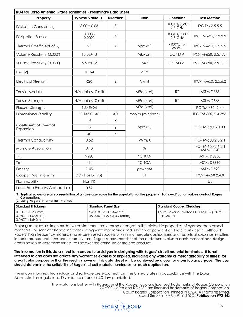
RO4730 LoPro Antenna Grade Laminates - Preliminary Data Sheet
Property Typical Value [1] Direction Units Condition Test Method
Dielectric Constant, r3.00 ± 0.08 Z 10 GHz/23°C
2.5 GHz IPC-TM-2.5.5.5
Dissipation Factor0.00330.0023 Z 10 GHz/23°C
2.5 GHz IPC-TM-650, 2.5.5.5
Thermal Coef cient of r 23 Z ppm/°C -100°C to 250°C IPC-TM-650, 2.5.5.5
Volume Resistivity (0.030") 1.40E+13 MΩ•cm COND A IPC-TM-650, 2.5.17.1
Surface Resistivity (0.030") 5.50E+12 MΩ COND A IPC-TM-650, 2.5.17.1
PIM [2] <-154 dBc
Electrical Strength 620 Z V/mil IPC-TM-650, 2.5.6.2
Tensile Modulus N/A (thin <10 mil) MPa (kpsi) RT ASTM D638
Tensile Strength N/A (thin <10 mil) MPa (kpsi) RT ASTM D638
Flexural Strength 1.34E+04 MPa (kpsi) IPC-TM-650, 2.4.4
Dimensional Stability -0.14/-0.145 X,Y mm/m (mils/inch) IPC-TM-650, 2.4.39A
Coef cient of Thermal Expansion
19 X
ppm/°C IPC-TM-650, 2.1.4117 Y
40 Z
Thermal Conductivity 0.52 W/m/K IPC-TM-650 2.5.2.1
Moisture Absorption 0.13 % IPC-TM-650 2.6.2.1 ASTM D570
Tg >280 °C TMA ASTM D3850
Td 441 °C TGA ASTM D3850
Density 1.45 gm/cm3 ASTM D792
Copper Peel Strength 7.7 (1 oz LoPro) pli IPC-TM-650 2.4.8
Flammability Non FR UL
Lead-Free Process Compatible YES
Prolonged exposure in an oxidative environment may cause changes to the dielectric properties of hydrocarbon based materials. The rate of change increases at higher temperatures and is highly dependent on the circuit design. Although Rogers’ high frequency materials have been used successfully in innumerable applications and reports of oxidation resulting in performance problems are extremely rare, Rogers recommends that the customer evaluate each material and design combination to determine tness for use over the entire life of the end product.
The information in this data sheet is intended to assist you in designing with Rogers’ circuit material laminates. It is not intended to and does not create any warranties express or implied, including any warranty of merchantability or fi tness for a particular purpose or that the results shown on this data sheet will be achieved by a user for a particular purpose. The usershould determine the suitability of Rogers’ circuit material laminates for each application.
These commodities, technology and software are exported from the United States in accordance with the Export Administration regulations. Diversion contrary to U.S. law prohibited.
The world runs better with Rogers. and the Rogers’ logo are licensed trademarks of Rogers CorporationRO4000, LoPro and RO4730 are licensed trademarks of Rogers Corporation.
©2009 Rogers Corporation, Printed in U.S.A. All rights reserved.Issued 06/2009 0865-0609-0.5CC Publication #92-142
[1] Typical values are a representation of an average value for the population of the property. For specifi cation values contact Rogers Corporation.
[2] Using Rogers’ internal test method.
Standard Thickness Standard Panel Size: Standard Copper Cladding
0.0307” (0.780mm)0.0407” (1.034mm)0.0607” (1.542mm)
24”X18” (610 X 457 mm)48”X36” (1.224 X 0.915mm)
LoPro Reverse Treated EDC Foil: ½ (18 m),1 oz (35 m)
Data SheetRO3730 Data Sheet
Advanced Circuit Materials
Advanced Circuit Materials Division100 S. Roosevelt Avenue
Chandler, AZ 85226Tel: 480-961-1382, Fax: 480-961-4533
www.rogerscorp.com
The world runs better with Rogers.®
RO3730™ Antenna Grade Laminates
Features: Benefi ts:
RO3730™ reinforced woven ber glass with optimized glass and ller loading
Improved mechanical rigidity/easier handling and processing •versus non-reinforced PTFE productsLower dissipation factor•Low PIM•PTH process capability•
Low PIM Reduced signal interference•
Low Loss Improved antenna gain•
Economically priced Volume manufacturing•
Environmentally friendly Lead-free process compatible•RoHS compliant•
Regional nished goods inventories Short lead times / quick inventory turns•Ef cient supply chain•
Typical Applications:
• Base Station Antennas
• RFID Antennas
• WLAN Antennas
• Satellite Radio Antennas
RO3730 laminates have the excellent thermo-mechanical properties, and electrical characteristics that antenna designers need. The laminates have a dielectric constant (Dk) of 3.0 and a loss tangent (Df) of 0.0013 measured at 2.5 GHz. These values allow antenna designers to realize substantial gain values while minimizing signal loss. Materials are available with a demonstrated low PIM performance, with values better than -154 dBc* (using Rogers’ internal test method).
RO3730 materials can be fabricated into printed circuit boards using standard PTFE circuit board processing techniques as described in the application note, “Fabrication Guidelines for RO3730 High Frequency Circuit Materials.”
Cladding is 1 ounce rolled annealed copper (35 m thick). RO3730 laminates are manufactured under an ISO 9002 certi ed quality system.
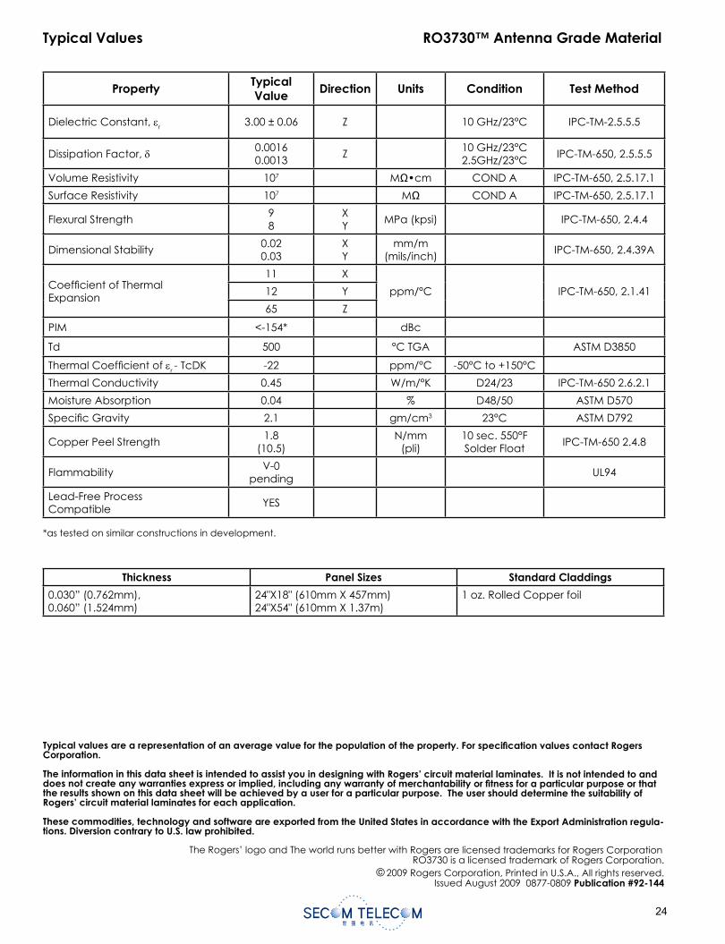
Typical Values RO3730™ Antenna Grade Material
Property TypicalValue Direction Units Condition Test Method
Dielectric Constant, r 3.00 ± 0.06 Z 10 GHz/23°C IPC-TM-2.5.5.5
Dissipation Factor, 0.00160.0013
Z10 GHz/23°C2.5GHz/23°C
IPC-TM-650, 2.5.5.5
Volume Resistivity 107 MΩ•cm COND A IPC-TM-650, 2.5.17.1
Surface Resistivity 107 MΩ COND A IPC-TM-650, 2.5.17.1
Flexural Strength98
XY
MPa (kpsi) IPC-TM-650, 2.4.4
Dimensional Stability0.020.03
XY
mm/m(mils/inch)
IPC-TM-650, 2.4.39A
Coef cient of Thermal Expansion
11 X
ppm/°C IPC-TM-650, 2.1.4112 Y
65 Z
PIM <-154* dBc
Td 500 °C TGA ASTM D3850
Thermal Coef cient of r - TcDK -22 ppm/°C -50°C to +150°C
Thermal Conductivity 0.45 W/m/°K D24/23 IPC-TM-650 2.6.2.1
Moisture Absorption 0.04 % D48/50 ASTM D570
Speci c Gravity 2.1 gm/cm3 23°C ASTM D792
Copper Peel Strength1.8
(10.5)N/mm
(pli)10 sec. 550°F Solder Float
IPC-TM-650 2.4.8
FlammabilityV-0
pendingUL94
Lead-Free Process Compatible
YES
*as tested on similar constructions in development.
Thickness Panel Sizes Standard Claddings
0.030” (0.762mm), 0.060” (1.524mm)
24"X18" (610mm X 457mm) 24"X54" (610mm X 1.37m)
1 oz. Rolled Copper foil
Typical values are a representation of an average value for the population of the property. For specifi cation values contact Rogers Corporation.
The information in this data sheet is intended to assist you in designing with Rogers’ circuit material laminates. It is not intended to and does not create any warranties express or implied, including any warranty of merchantability or fi tness for a particular purpose or that the results shown on this data sheet will be achieved by a user for a particular purpose. The user should determine the suitability of Rogers’ circuit material laminates for each application.
These commodities, technology and software are exported from the United States in accordance with the Export Administration regula-tions. Diversion contrary to U.S. law prohibited.
The Rogers’ logo and The world runs better with Rogers are licensed trademarks for Rogers CorporationRO3730 is a licensed trademark of Rogers Corporation.
© 2009 Rogers Corporation, Printed in U.S.A., All rights reserved.Issued August 2009 0877-0809 Publication #92-144
Data Sheet and Processing Guidelines for RO4403™, RO4450B™ and RO4450F™ Prepregs
RO4000® dielectric materials have long been used in combination with FR4 cores and prepreg as a means to achieve a performance upgrade of standard FR4 multilayer designs. RO4003C™ and RO4350B™ glassreinforced hydrocarbon/ceramic laminates have been used in layers where operating frequency, dielec-tric constant, or high-speed signal requirements dictate the need for high performance materials. FR4 cores and prepreg are still commonly used to inexpensively form less critical signal layers.
The RO4400™ prepreg family is comprised of three grades based on the RO4000 series core materials, and are compatible in multilayer constructions with either RO4003C or RO4350B laminates. A high post-cure Tg (>280°C) makes RO4400 series prepreg an excellent choice for multilayers requiring sequential laminations as fully cured RO4400 prepregs are capable of handling multiple lamination cycles. In addition, FR4 capat-ible bond requirements (350°F/177°C) permit RO4400 prepreg and low fl ow FR4 prepreg to be combined into non-homegeneos multilayer constructions using a single bond cycle.
RO4450F™ prepreg is the latest product in the RO4400 family of prepregs. RO4450F prepreg has demonstrat-ed improvement in lateral fl ow capability, and is becoming the fi rst choice for new designs or as a replace-ment in designs that have diffi cult fi ll requirements.
RO4450B™ prepreg is available in both 3.6 mil and 4.0 mil thicknesses. The electrical properties of these two prepreg thicknesses differ slightly due to the resin-to-glass ratio, and this should be taken into consideration during electrical design review.
Each of the RO4450™ series prepregs are recognized by Underwriter Laboratories with the UL-94 fl ame rat-ing, and are compatible with lead-free processes.
PROCESSING GUIDELINES:
STORAGE:Upon receipt, all prepreg should be immediately moved from the receiving area into a controlled environment. Proper storage conditions would include temperatures between 10°C and 30°C (50°F and 85°F) and protection against exposure to catalytic conditions such as high radiation and ultraviolet light. The prepreg should not be stored under vacuum. It is best to store the prepreg in its heat sealed packaging, partially used packages should be resealed with tape.
When properly stored, prepreg properties will be maintained for 12 months from the date of manufacture.A “fi rst-in, fi rst-out” inventory system is recommended.
UNPACKING:RO4400 prepregs are packaged in a dust-free environment, but will collect dust and debris from counter tops. We recommend counter tops be cleaned prior to unpackaging the prepreg. Plastic slip-sheeting has been provided to ease separation of individual plies and to shield the prepreg from contamination until it is ready for use.
Advanced Circuit Materials
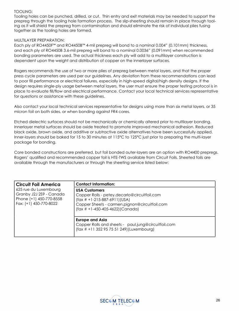
The information contained in this data sheet and processing guide is intended to assist you in designing with Rogers’ circuit materialsand prepreg. It is not intended to and does not create any warranties, express or implied, including any warranty of merchantabilityor fi tness for a particular purpose or that the results shown on this data sheet and processing guide will be achieved by a user for a particular purpose. The user is responsible for determining the suitability of Rogers’ circuit materials and prepreg for each application.
Page 2 of 4
TOOLING:Tooling holes can be punched, drilled, or cut. Thin entry and exit materials may be needed to support the prepreg through the tooling hole formation process. The slip-sheeting should remain in place through tool-ing as it will shield the prepreg from contamination and should eliminate the risk of individual plies fusing together as the tooling holes are formed.
MULTILAYER PREPARATION:Each ply of RO4450F™ and RO4450B™ 4-mil prepreg will bond to a nominal 0.004” (0.101mm) thickness, and each ply of RO4450B 3.6-mil prepreg will bond to a nominal 0.0036” (0.091mm) when recommended bonding parameters are used. The actual thickness each ply will add to a multilayer construction is dependent upon the weight and distribution of copper on the innerlayer surfaces.
Rogers recommends the use of two or more plies of prepreg between metal layers, and that the proper press cycle parameters are used per our guidelines. Any deviation from these recommendations can lead to poor fi ll performance or electrical failures, especially in high-speed digital/high density designs. If the design requires single-ply usage between metal layers, the user must ensure the proper testing protocol is in place to evaluate fi ll/fl ow and electrical performance. Contact your local technical services representative for questions or assistance with these guidelines.
Also contact your local technical services representative for designs using more than six metal layers, or 35 micron foil on both sides, or when bonding against FR4 cores.
Etched dielectric surfaces should not be mechanically or chemically altered prior to multilayer bonding.Innerlayer metal surfaces should be oxide treated to promote improved mechanical adhesion. Reduced black oxide, brown oxide, and additive or subtractive oxide alternatives have been successfully applied. Inner-layers should be baked for 15 to 30 minutes at 115°C to 125°C just prior to preparing the multi-layer package for bonding.
Core bonded constructions are preferred, but foil bonded outer-layers are an option with RO4400 prepregs. Rogers’ qualifi ed and recommended copper foil is HTE-TWS available from Circuit Foils. Sheeted foils are available through the manufacturers or through the sheeting service listed below:
Circuit Foil America 625 rue du Luxembourg Granby J2J 2S9 - Canada Phone (+1) 450-770-8558 Fax: (+1) 450-770-8022
Contact Information:
USA CustomersCopper Rolls - [email protected](fax # +1-215-887-6911)(USA)Copper Sheets - [email protected](fax # +1-450-405-4622)(Canada)
Europe and AsiaCopper Rolls and sheets - [email protected] (fax # +11 352 95 75 51 249)(Luxembourg)
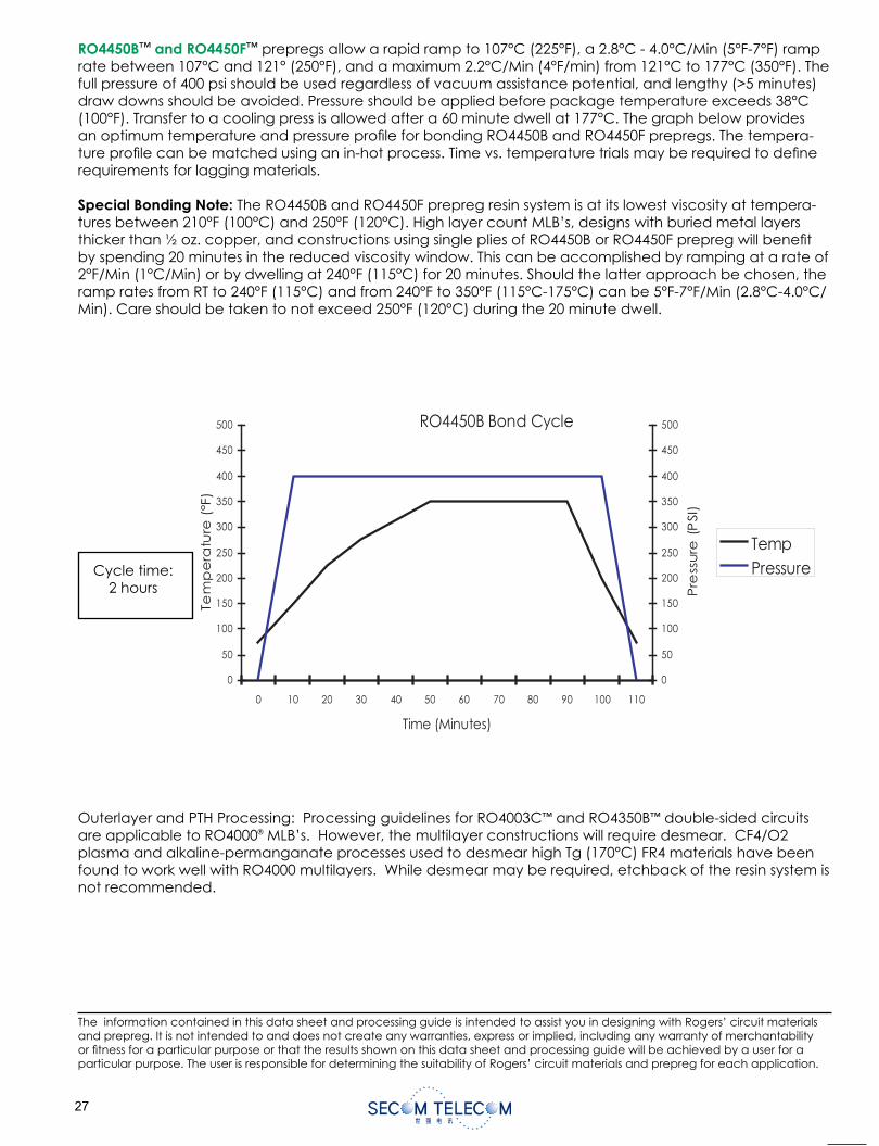
The information contained in this data sheet and processing guide is intended to assist you in designing with Rogers’ circuit materialsand prepreg. It is not intended to and does not create any warranties, express or implied, including any warranty of merchantabilityor fi tness for a particular purpose or that the results shown on this data sheet and processing guide will be achieved by a user for a particular purpose. The user is responsible for determining the suitability of Rogers’ circuit materials and prepreg for each application.
Page 3 of 4
RO4450B™ and RO4450F™ prepregs allow a rapid ramp to 107°C (225°F), a 2.8°C - 4.0°C/Min (5°F-7°F) ramp rate between 107°C and 121° (250°F), and a maximum 2.2°C/Min (4°F/min) from 121°C to 177°C (350°F). The full pressure of 400 psi should be used regardless of vacuum assistance potential, and lengthy (>5 minutes) draw downs should be avoided. Pressure should be applied before package temperature exceeds 38°C (100°F). Transfer to a cooling press is allowed after a 60 minute dwell at 177°C. The graph below provides an optimum temperature and pressure profi le for bonding RO4450B and RO4450F prepregs. The tempera-ture profi le can be matched using an in-hot process. Time vs. temperature trials may be required to defi ne requirements for lagging materials.
Special Bonding Note: The RO4450B and RO4450F prepreg resin system is at its lowest viscosity at tempera-tures between 210°F (100°C) and 250°F (120°C). High layer count MLB’s, designs with buried metal layers thicker than ½ oz. copper, and constructions using single plies of RO4450B or RO4450F prepreg will benefi t by spending 20 minutes in the reduced viscosity window. This can be accomplished by ramping at a rate of 2°F/Min (1°C/Min) or by dwelling at 240°F (115°C) for 20 minutes. Should the latter approach be chosen, the ramp rates from RT to 240°F (115°C) and from 240°F to 350°F (115°C-175°C) can be 5°F-7°F/Min (2.8°C-4.0°C/Min). Care should be taken to not exceed 250°F (120°C) during the 20 minute dwell.
Outerlayer and PTH Processing: Processing guidelines for RO4003C™ and RO4350B™ double-sided circuits are applicable to RO4000® MLB’s. However, the multilayer constructions will require desmear. CF4/O2 plasma and alkaline-permanganate processes used to desmear high Tg (170°C) FR4 materials have been found to work well with RO4000 multilayers. While desmear may be required, etchback of the resin system is not recommended.
Cycle time:2 hours
STANDARD THICKNESS:RO4403/RO4450B: 0.004” (0.101mm)RO4450F: 0.004” (0.101mm)
STANDARD SIZE:24X18” Sheets (610mm X 457mm) Contact Customer Service for other available sizes.
DOHTEM TSETNOITIDNOCSTINUNOITCERIDYTREPORPRO4450FRO4450B
TYPICAL VALUES
RO4403
Thickness 4 (0.10) 4 (0.10) 4 (0.102) Z mils (mm) - -
Dielectric Constant , εr 3.17 ± 0.05 3.54 ± 0.05 3.52 ± 0.05 Z - 10GHz - 23°C IPC-TM-650, 2.5.5.5
Dissipation Factor, tan δ 0.005 0.004 0.004 Z - 10GHz-23°C IPC-TM-650, 2.5.5.5
Dielectric Strength 1000 1000 1000 Z V/mil 23°C/50% RH IPC-TM-650, 2.5.6
VolumeResistivity
3.3 X 10¹⁰ >2.5 X 10¹⁰ TBD - MΩ•cm 23°C/50% RH IPC-TM-650, 2.5.17.1
SurfaceResistivity
1.9X10⁸ 1.9 X 10⁸ TBD X,Y MΩ 23°C/50% RH IPC-TM-650, 2.5.17.1
ThermalConductivity
0.46 0.60 0.65 Z W/m/K 100°C ASTM F433
MoistureAbsorption
0.05 0.05 0.09 - %
48 hrs immersion
0.060” sample temperature
50°C
ASTM D570
AMT C°-082>082>082>gT-60°C - 300°C @ 10°C/min
IPC-TM-650 2.4.24
0583D MTSAAGT C°-093093093dT
mc/mg-38.168.156.1ytisneD 3 23°C ASTM D792
Dimensional Stability 0.6 TBD -0.065 X,Y mils/inchAfter Etch +E2/150
IPC-TM-650, 2.2.4
CopperAdhesion
5* (0.88) 4.9* (0.86) 4.0* (0.70) Z pli (N/mm)After Solder
FloatIPC-TM-650, 2.4.8
Coeffi cient of Thermal Expansion
161980
191760
191750
XYZ
ppm/°C -55 to 125°C IPC-TM-650, 2.4.41
----etihWetihWetihWroloC
Flammability - 94V-0 94 V-0
Lead-Free Process Compatible
Yes Yes Yes
*Tested on ½ oz. EDC foil for RO4450B and 1 oz. EDC foil for RO4403 prepreg.
Typical Values RO4403TM, RO4450BTM, RO4450FTM Prepreg
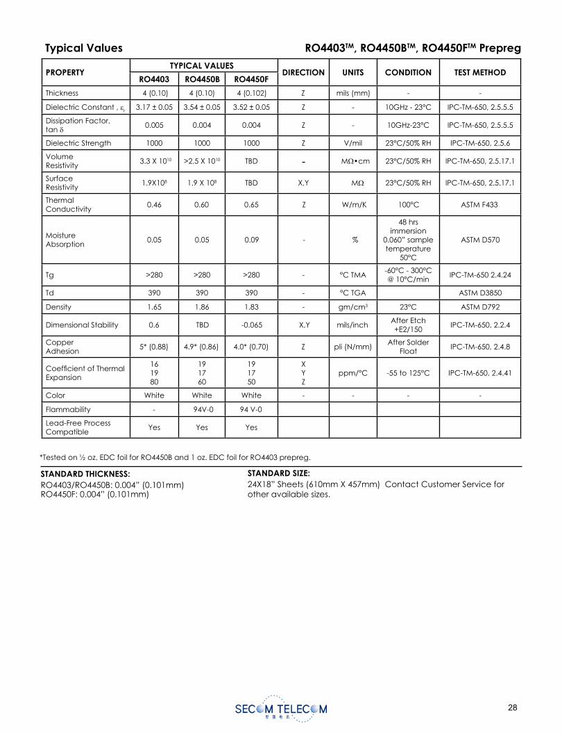
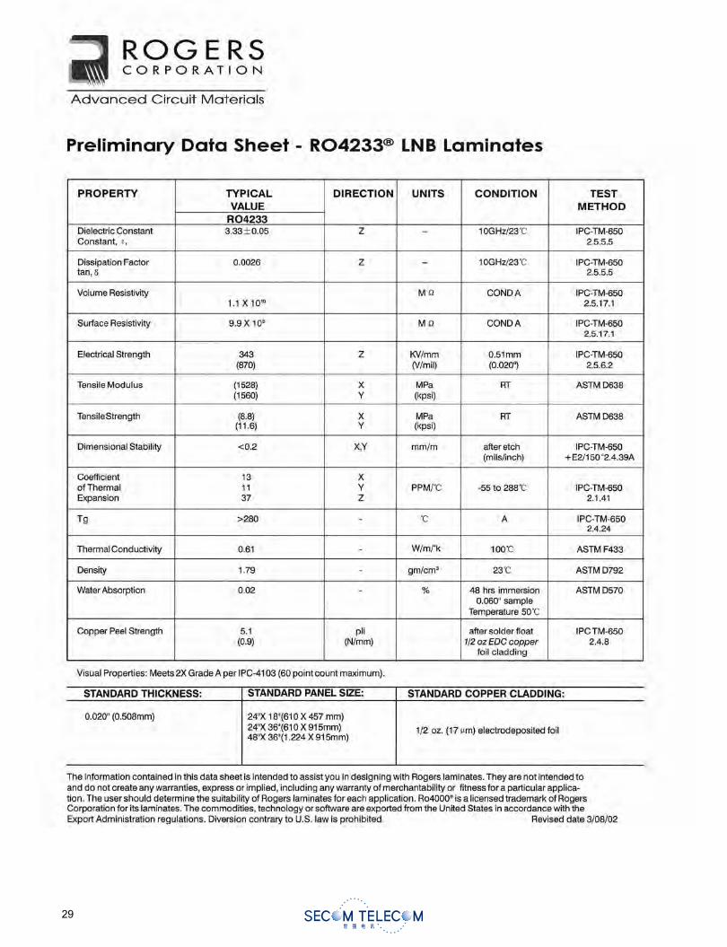
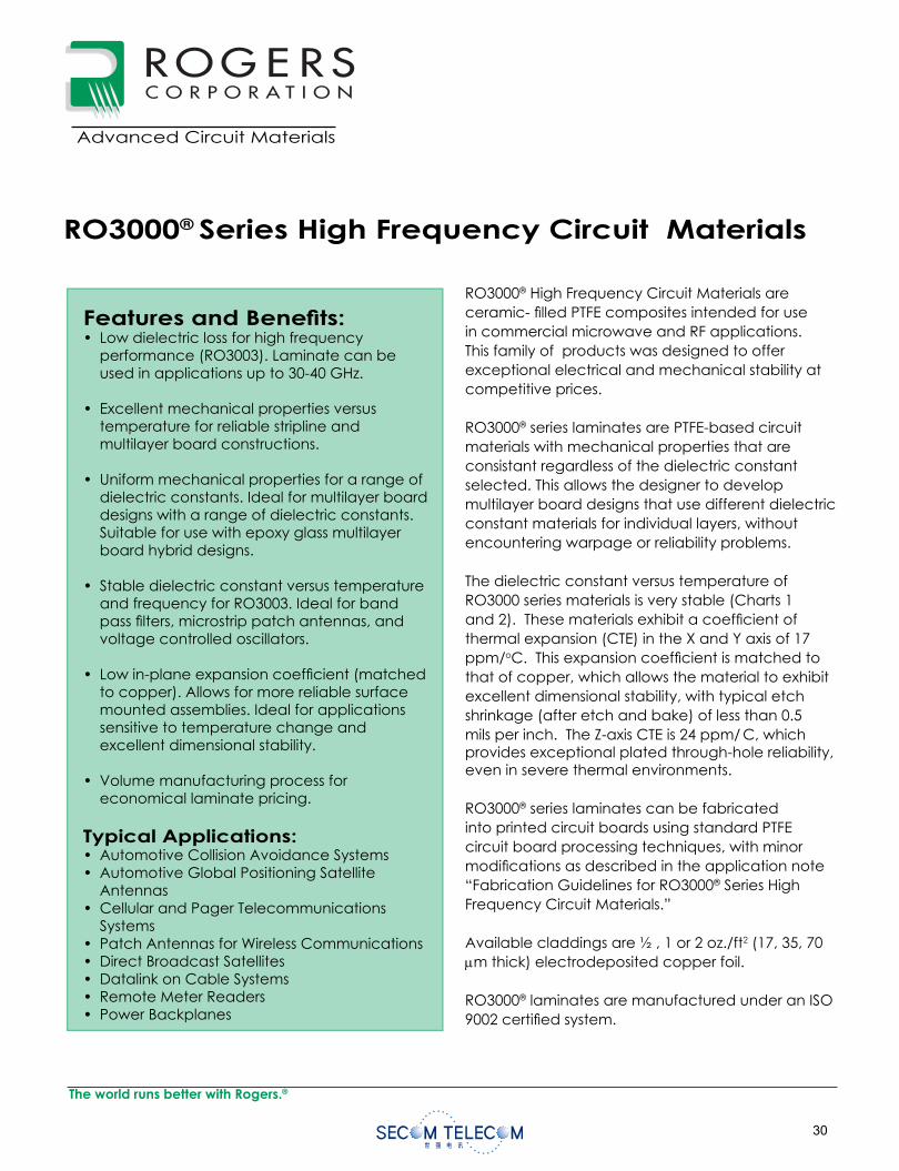
0
RO3000® Series High Frequency Circuit Materials
RO3000® High Frequency Circuit Materials are ceramic- fi lled PTFE composites intended for use in commercial microwave and RF applications. This family of products was designed to offer exceptional electrical and mechanical stability at competitive prices.
RO3000® series laminates are PTFE-based circuit materials with mechanical properties that areconsistant regardless of the dielectric constant selected. This allows the designer to develop multilayer board designs that use different dielectric constant materials for individual layers, without encountering warpage or reliability problems.
The dielectric constant versus temperature of RO3000 series materials is very stable (Charts 1 and 2). These materials exhibit a coeffi cient of thermal expansion (CTE) in the X and Y axis of 17 ppm/oC. This expansion coeffi cient is matched to that of copper, which allows the material to exhibit excellent dimensional stability, with typical etch shrinkage (after etch and bake) of less than 0.5 mils per inch. The Z-axis CTE is 24 ppm/ C, which provides exceptional plated through-hole reliability, even in severe thermal environments.
RO3000® series laminates can be fabricated into printed circuit boards using standard PTFE circuit board processing techniques, with minor modifi cations as described in the application note “Fabrication Guidelines for RO3000® Series High Frequency Circuit Materials.”
Available claddings are ½ , 1 or 2 oz./ft2 (17, 35, 70 m thick) electrodeposited copper foil.
RO3000® laminates are manufactured under an ISO 9002 certifi ed system.
Data Sheet1.3000
Advanced Circuit Materials
Advanced Circuit Materials Division100 S. Roosevelt Avenue
Chandler, AZ 85226Tel: 480-961-1382, Fax: 480-961-4533
www.rogerscorporation.com
Features and Benefi ts:• Low dielectric loss for high frequency
performance (RO3003). Laminate can be used in applications up to 30-40 GHz.
• Excellent mechanical properties versus temperature for reliable stripline and multilayer board constructions.
• Uniform mechanical properties for a range of dielectric constants. Ideal for multilayer board designs with a range of dielectric constants. Suitable for use with epoxy glass multilayer board hybrid designs.
• Stable dielectric constant versus temperature and frequency for RO3003. Ideal for band pass fi lters, microstrip patch antennas, and voltage controlled oscillators.
• Low in-plane expansion coeffi cient (matched to copper). Allows for more reliable surface mounted assemblies. Ideal for applications sensitive to temperature change and excellent dimensional stability.
• Volume manufacturing process for economical laminate pricing.
Typical Applications:• Automotive Collision Avoidance Systems• Automotive Global Positioning Satellite
Antennas• Cellular and Pager Telecommunications
Systems• Patch Antennas for Wireless Communications• Direct Broadcast Satellites• Datalink on Cable Systems• Remote Meter Readers• Power Backplanes
The world runs better with Rogers.®
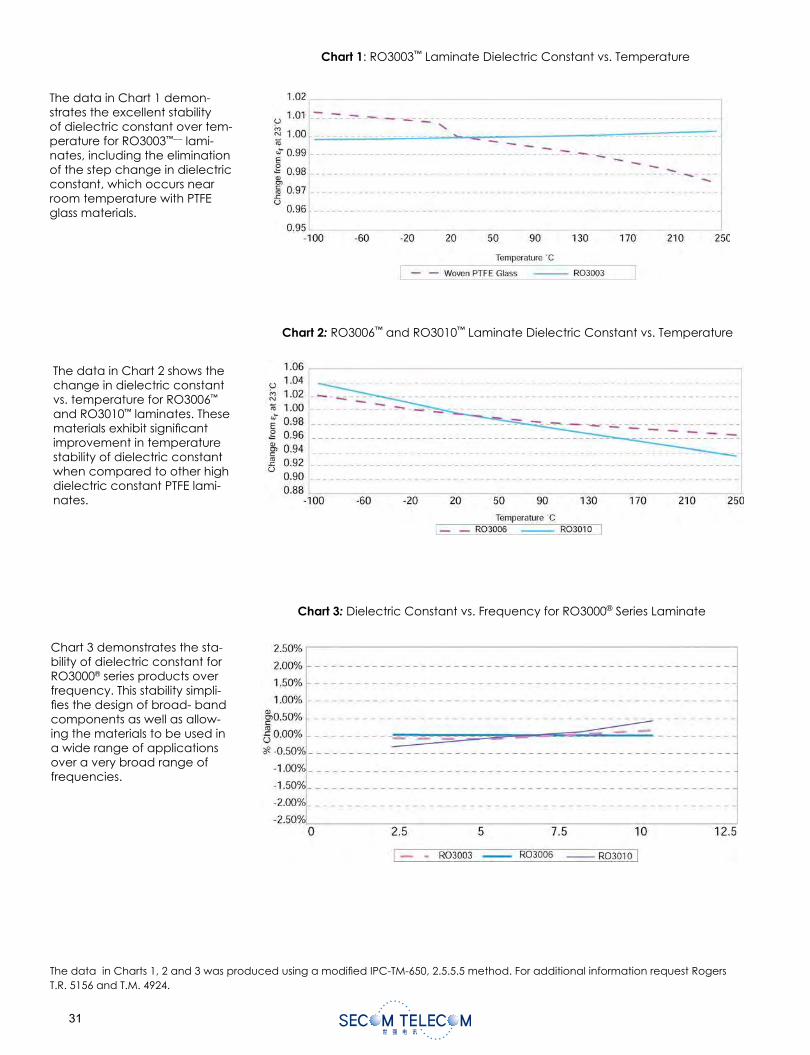
The data in Chart 1 demon-strates the excellent stability of dielectric constant over tem-perature for RO3003™––- lami-nates, including the elimination of the step change in dielectric constant, which occurs near room temperature with PTFE glass materials.
Chart 1: RO3003™ Laminate Dielectric Constant vs. Temperature
Chart 2: RO3006™ and RO3010™ Laminate Dielectric Constant vs. Temperature
Chart 3: Dielectric Constant vs. Frequency for RO3000® Series Laminate
The data in Chart 2 shows the change in dielectric constant vs. temperature for RO3006™
and RO3010™ laminates. These materials exhibit signifi cant improvement in temperature stability of dielectric constant when compared to other high dielectric constant PTFE lami-nates.
Chart 3 demonstrates the sta-bility of dielectric constant for RO3000® series products over frequency. This stability simpli-fi es the design of broad- band components as well as allow-ing the materials to be used in a wide range of applications over a very broad range of frequencies.
The data in Charts 1, 2 and 3 was produced using a modifi ed IPC-TM-650, 2.5.5.5 method. For additional information request Rogers T.R. 5156 and T.M. 4924.
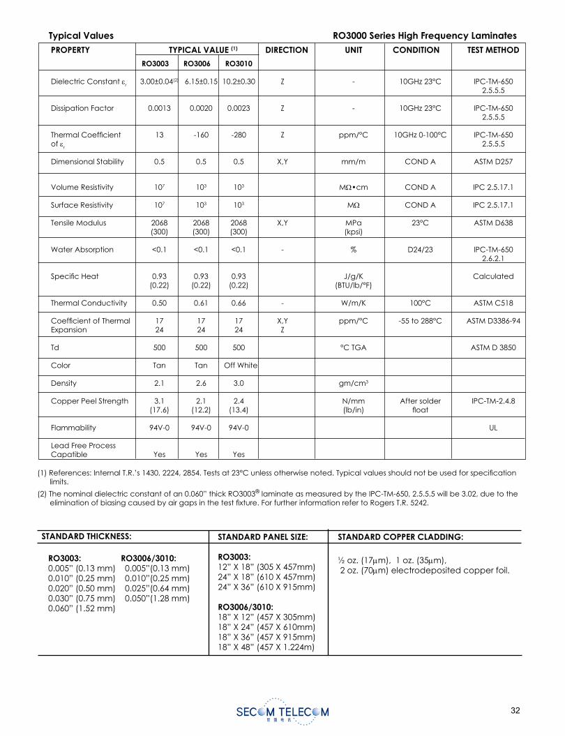
(1) References: Internal T.R.’s 1430, 2224, 2854. Tests at 23°C unless otherwise noted. Typical values should not be used for specifi cation limits.
(2) The nominal dielectric constant of an 0.060” thick RO3003® laminate as measured by the IPC-TM-650, 2.5.5.5 will be 3.02, due to the elimination of biasing caused by air gaps in the test fi xture. For further information refer to Rogers T.R. 5242.
PROPERTY TYPICAL VALUE (1) DIRECTION UNIT CONDITION TEST METHOD
RO3003 RO3006 RO3010
Dielectric Constant r 3.00±0.04(2) 6.15±0.15 10.2±0.30 Z - 10GHz 23°C IPC-TM-650 2.5.5.5
Dissipation Factor 0.0013 0.0020 0.0023 Z - 10GHz 23°C IPC-TM-650 2.5.5.5
Thermal Coeffi cient 13 -160 -280 Z ppm/°C 10GHz 0-100°C IPC-TM-650of r 2.5.5.5
Dimensional Stability 0.5 0.5 0.5 X,Y mm/m COND A ASTM D257
Volume Resistivity 107 103 103 M •cm COND A IPC 2.5.17.1
Surface Resistivity 107 103 103 M COND A IPC 2.5.17.1
Tensile Modulus 2068 2068 2068 X,Y MPa 23°C ASTM D638 (300) (300) (300) (kpsi)
Water Absorption <0.1 <0.1 <0.1 - % D24/23 IPC-TM-650 2.6.2.1
Specifi c Heat 0.93 0.93 0.93 J/g/K Calculated (0.22) (0.22) (0.22) (BTU/lb/°F) Thermal Conductivity 0.50 0.61 0.66 - W/m/K 100°C ASTM C518
Coeffi cient of Thermal 17 17 17 X,Y ppm/°C -55 to 288°C ASTM D3386-94Expansion 24 24 24 Z
Td 500 500 500 °C TGA ASTM D 3850 Color Tan Tan Off White
Density 2.1 2.6 3.0 gm/cm3
Copper Peel Strength 3.1 2.1 2.4 N/mm After solder IPC-TM-2.4.8 (17.6) (12.2) (13.4) (lb/in) fl oat
Flammability 94V-0 94V-0 94V-0 UL
Lead Free ProcessCapatible Yes Yes Yes
Typical Values RO3000 Series High Frequency Laminates
STANDARD THICKNESS:
STANDARD PANEL SIZE:
RO3003:12” X 18” (305 X 457mm)24” X 18” (610 X 457mm)24” X 36” (610 X 915mm)
RO3006/3010:18” X 12” (457 X 305mm)18” X 24” (457 X 610mm)18” X 36” (457 X 915mm)18” X 48” (457 X 1.224m)
STANDARD COPPER CLADDING:
½ oz. (17 m), 1 oz. (35 m), 2 oz. (70 m) electrodeposited copper foil.
RO3003: RO3006/3010: 0.005” (0.13 mm) 0.005”(0.13 mm) 0.010” (0.25 mm) 0.010”(0.25 mm)0.020” (0.50 mm) 0.025”(0.64 mm)0.030” (0.75 mm) 0.050”(1.28 mm) 0.060” (1.52 mm)
RO3035™ High Frequency Circuit MaterialsRO3000® high frequency circuit materials are ceramic- fi lled PTFE composites intended for use in commercial microwave and RF applications. This family of products was designed to offer exceptional electrical and mechanical stability at competitive prices.
RO3000 series laminates are ceramic-fi lled PTFE based circuit materials with mechanical properties that are consistent regardless of the dielectric constant selected. This allows the designer to develop multilayer board designs that use different dielectric constant materials for individual layers, without encountering warpage or reliability problems.
The dielectric constant versus temperature of RO3000 series materials is very stable . These materials exhibit a coeffi cient of thermal expansion (CTE) in the X and Y axis of 17 ppm/oC. This expansion coeffi cient is matched to that of copper, which allows the material to exhibit excellent dimensional stability and minimizes the tendency for bow and twist. This matched expansion coeffi cient also eliminates the tendency for delamination for thick metal cladding. The Z-axis CTE is 24 ppm/ C,which provides exceptional plated through-hole reliability, even in severe thermal environments.
RO3000 series laminates can be fabricated into printed circuit boards using standard PTFE circuit board processing techniques, with minor modifi cations as described in the application note “Fabrication Guidelines for RO3000 Series High Frequency Circuit Materials.”
Available claddings are 1/2, 1, 2 copper foil and custom thick metal plates per customer specifi cations.
RO3000 laminates are manufactured under an ISO 9002 certifi ed system.
Data Sheet1.3035
Advanced Circuit Materials
Advanced Circuit Materials Division100 S. Roosevelt Avenue
Chandler, AZ 85226Tel: 480-961-1382, Fax: 480-961-4533
www.rogerscorp.com
Features and Benefi ts:
• Low dielectric loss for high frequency performance. Laminate can be used in applications up to 30-40 GHz.
• Excellent mechanical properties versus temperature for reliable stripline and multilayer board constructions.
• Uniform mechanical properties for a range of dielectric constants. Ideal for multilayer board designs with a range of dielectric constants. Suitable for use with epoxy glass multilayer board hybrid designs.
• Stable dielectric constant versus temperature and frequency. Ideal for band pass fi lters, microstrip patch antennas, and voltage controlled oscillators.
• Low in-plane expansion coeffi cient (matched to copper). Allows for more reliable surface mounted assemblies. Ideal for applications sensitive to temperature change and excellent dimensional stability.
• High thermal conductivity for lower operating temperature and increased reliability in Power Amplifi er applications.
The world runs better with Rogers.®
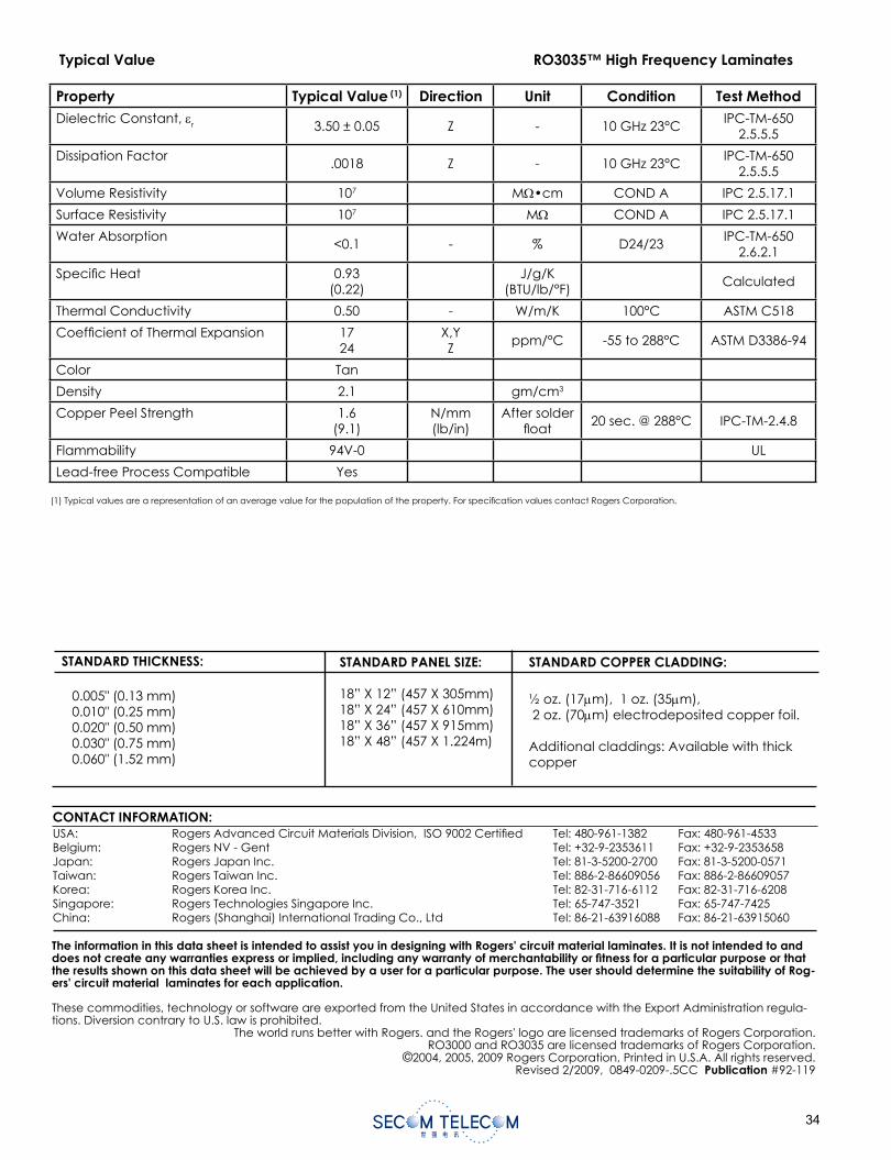
(1) Typical values are a representation of an average value for the population of the property. For specifi cation values contact Rogers Corporation.
The information in this data sheet is intended to assist you in designing with Rogers' circuit material laminates. It is not intended to and does not create any warranties express or implied, including any warranty of merchantability or fi tness for a particular purpose or that the results shown on this data sheet will be achieved by a user for a particular purpose. The user should determine the suitability of Rog-ers' circuit material laminates for each application.
These commodities, technology or software are exported from the United States in accordance with the Export Administration regula-tions. Diversion contrary to U.S. law is prohibited.
The world runs better with Rogers. and the Rogers' logo are licensed trademarks of Rogers Corporation.RO3000 and RO3035 are licensed trademarks of Rogers Corporation.
©2004, 2005, 2009 Rogers Corporation, Printed in U.S.A. All rights reserved.Revised 2/2009, 0849-0209-.5CC Publication #92-119
Typical Value RO3035™ High Frequency Laminates
CONTACT INFORMATION:USA: Rogers Advanced Circuit Materials Division, ISO 9002 Certifi ed Tel: 480-961-1382 Fax: 480-961-4533Belgium: Rogers NV - Gent Tel: +32-9-2353611 Fax: +32-9-2353658Japan: Rogers Japan Inc. Tel: 81-3-5200-2700 Fax: 81-3-5200-0571Taiwan: Rogers Taiwan Inc. Tel: 886-2-86609056 Fax: 886-2-86609057Korea: Rogers Korea Inc. Tel: 82-31-716-6112 Fax: 82-31-716-6208Singapore: Rogers Technologies Singapore Inc. Tel: 65-747-3521 Fax: 65-747-7425China: Rogers (Shanghai) International Trading Co., Ltd Tel: 86-21-63916088 Fax: 86-21-63915060
STANDARD THICKNESS:
STANDARD PANEL SIZE:
18” X 12” (457 X 305mm)18” X 24” (457 X 610mm)18” X 36” (457 X 915mm)18” X 48” (457 X 1.224m)
STANDARD COPPER CLADDING:
½ oz. (17 m), 1 oz. (35 m), 2 oz. (70 m) electrodeposited copper foil.
Additional claddings: Available with thick copper
0.005" (0.13 mm)0.010" (0.25 mm)0.020" (0.50 mm)0.030" (0.75 mm)0.060" (1.52 mm)
Property Typical Value (1) Direction Unit Condition Test MethodDielectric Constant, r 3.50 ± 0.05 Z - 10 GHz 23°C
IPC-TM-6502.5.5.5
Dissipation Factor.0018 Z - 10 GHz 23°C
IPC-TM-6502.5.5.5
Volume Resistivity 107 M •cm COND A IPC 2.5.17.1
Surface Resistivity 107 M COND A IPC 2.5.17.1
Water Absorption<0.1 - % D24/23
IPC-TM-6502.6.2.1
Specifi c Heat 0.93(0.22)
J/g/K(BTU/lb/°F)
Calculated
Thermal Conductivity 0.50 - W/m/K 100°C ASTM C518
Coeffi cient of Thermal Expansion 1724
X,YZ
ppm/°C -55 to 288°C ASTM D3386-94
Color Tan
Density 2.1 gm/cm3
Copper Peel Strength 1.6(9.1)
N/mm(lb/in)
After solder fl oat
20 sec. @ 288°C IPC-TM-2.4.8
Flammability 94V-0 UL
Lead-free Process Compatible Yes
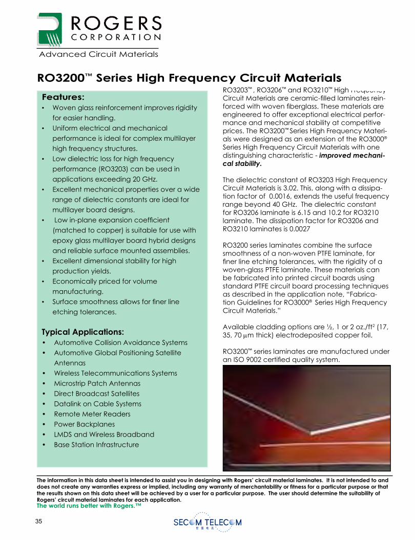
Data Sheet1.3200
The world runs better with Rogers.™
Advanced Circuit Materials
Advanced Circuit Materials Division100 S. Roosevelt Avenue
Chandler, AZ 85226Tel: 480-961-1382, Fax: 480-961-4533
www.rogerscorporation.com
RO3203™ , RO3206™ and RO3210™ High Frequency Circuit Materials are ceramic- lled laminates rein-forced with woven berglass. These materials are engineered to offer exceptional electrical perfor-mance and mechanical stability at competitive prices. The RO3200™ Series High Frequency Materi-als were designed as an extension of the RO3000®
Series High Frequency Circuit Materials with one distinguishing characteristic - improved mechani-cal stability.
The dielectric constant of RO3203 High Frequency Circuit Materials is 3.02. This, along with a dissipa-tion factor of 0.0016, extends the useful frequency range beyond 40 GHz. The dielectric constant for RO3206 laminate is 6.15 and 10.2 for RO3210 laminate. The dissipation factor for RO3206 and RO3210 laminates is 0.0027
RO3200 series laminates combine the surface smoothness of a non-woven PTFE laminate, for ner line etching tolerances, with the rigidity of a woven-glass PTFE laminate. These materials can be fabricated into printed circuit boards using standard PTFE circuit board processing techniques as described in the application note, “Fabrica-tion Guidelines for RO3000® Series High Frequency Circuit Materials.”
Available cladding options are ½, 1 or 2 oz./ft2 (17, 35, 70 m thick) electrodeposited copper foil.
RO3200™ series laminates are manufactured under an ISO 9002 certi ed quality system.
RO3200™ Series High Frequency Circuit Materials
Features:• Woven glass reinforcement improves rigidity
for easier handling.
• Uniform electrical and mechanical
performance is ideal for complex multilayer
high frequency structures.
• Low dielectric loss for high frequency
performance (RO3203) can be used in
applications exceeding 20 GHz.
• Excellent mechanical properties over a wide
range of dielectric constants are ideal for
multilayer board designs.
• Low in-plane expansion coef cient
(matched to copper) is suitable for use with
epoxy glass multilayer board hybrid designs
and reliable surface mounted assemblies.
• Excellent dimensional stability for high
production yields.
• Economically priced for volume
manufacturing.
• Surface smoothness allows for ner line
etching tolerances.
Typical Applications:• Automotive Collision Avoidance Systems
• Automotive Global Positioning Satellite
Antennas
• Wireless Telecommunications Systems
• Microstrip Patch Antennas
• Direct Broadcast Satellites
• Datalink on Cable Systems
• Remote Meter Readers
• Power Backplanes
• LMDS and Wireless Broadband
• Base Station Infrastructure
The information in this data sheet is intended to assist you in designing with Rogers’ circuit material laminates. It is not intended to and does not create any warranties express or implied, including any warranty of merchantability or tness for a particular purpose or that the results shown on this data sheet will be achieved by a user for a particular purpose. The user should determine the suitability of Rogers’ circuit material laminates for each application.
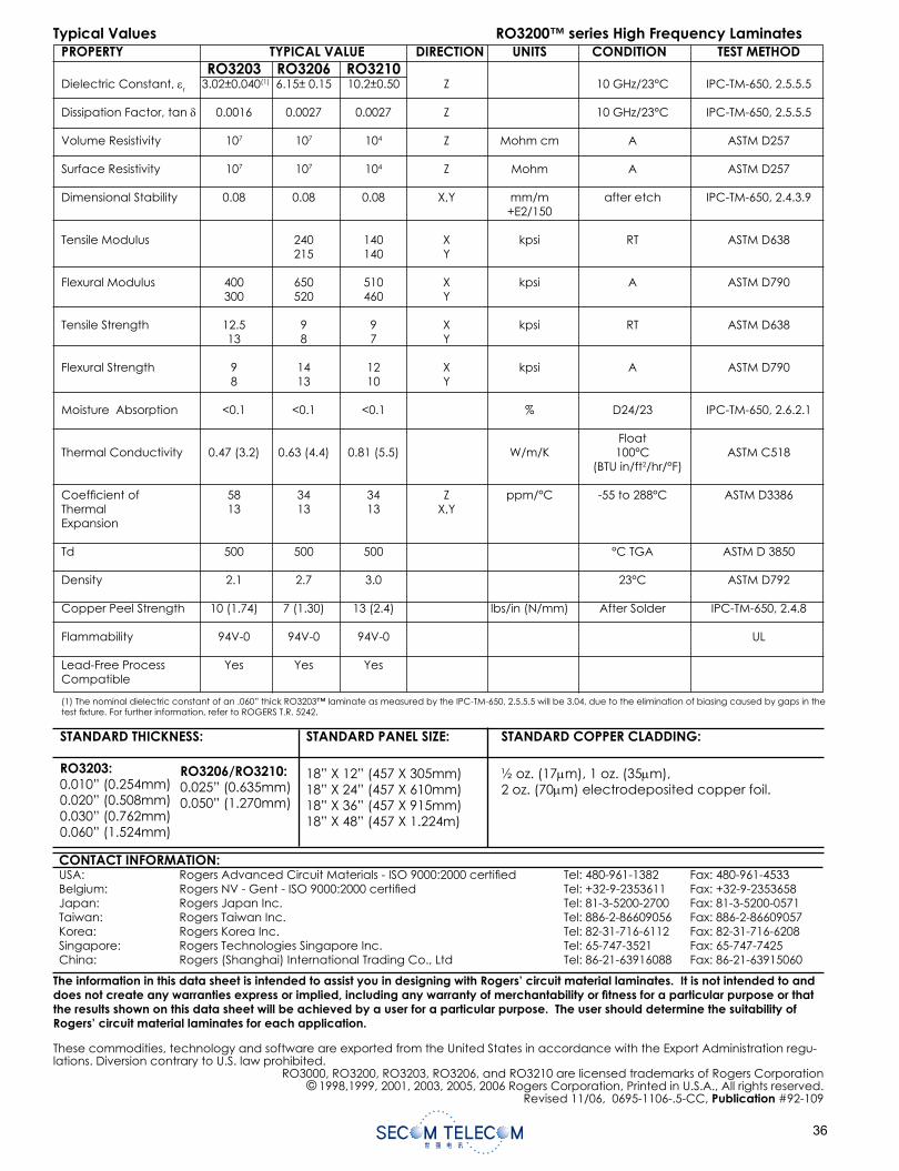
PROPERTY TYPICAL VALUE DIRECTION UNITS CONDITION TEST METHOD RO3203 RO3206 RO3210 Dielectric Constant, r 3.02±0.040(1) 6.15± 0.15 10.2±0.50 Z 10 GHz/23°C IPC-TM-650, 2.5.5.5
Dissipation Factor, tan 0.0016 0.0027 0.0027 Z 10 GHz/23°C IPC-TM-650, 2.5.5.5
Volume Resistivity 107 107 104 Z Mohm cm A ASTM D257
Surface Resistivity 107 107 104 Z Mohm A ASTM D257
Dimensional Stability 0.08 0.08 0.08 X,Y mm/m after etch IPC-TM-650, 2.4.3.9 +E2/150
Tensile Modulus 240 140 X kpsi RT ASTM D638 215 140 Y
Flexural Modulus 400 650 510 X kpsi A ASTM D790 300 520 460 Y
Tensile Strength 12.5 9 9 X kpsi RT ASTM D638 13 8 7 Y
Flexural Strength 9 14 12 X kpsi A ASTM D790 8 13 10 Y
Moisture Absorption <0.1 <0.1 <0.1 % D24/23 IPC-TM-650, 2.6.2.1
FloatThermal Conductivity 0.47 (3.2) 0.63 (4.4) 0.81 (5.5) W/m/K 100°C ASTM C518 (BTU in/ft2/hr/°F)
Coef cient of 58 34 34 Z ppm/°C -55 to 288°C ASTM D3386Thermal 13 13 13 X,Y Expansion
Td 500 500 500 °C TGA ASTM D 3850
Density 2.1 2.7 3.0 23°C ASTM D792
Copper Peel Strength 10 (1.74) 7 (1.30) 13 (2.4) lbs/in (N/mm) After Solder IPC-TM-650, 2.4.8
Flammability 94V-0 94V-0 94V-0 UL
Lead-Free Process Yes Yes Yes Compatible
(1) The nominal dielectric constant of an .060” thick RO3203™ laminate as measured by the IPC-TM-650, 2.5.5.5 will be 3.04, due to the elimination of biasing caused by gaps in the test xture. For further information, refer to ROGERS T.R. 5242.
STANDARD THICKNESS:
RO3203:0.010” (0.254mm)0.020” (0.508mm)0.030” (0.762mm)0.060” (1.524mm)
STANDARD PANEL SIZE:
18” X 12” (457 X 305mm)18” X 24” (457 X 610mm)18” X 36” (457 X 915mm)18” X 48” (457 X 1.224m)
STANDARD COPPER CLADDING:
½ oz. (17 m), 1 oz. (35 m),2 oz. (70 m) electrodeposited copper foil.
RO3206/RO3210:0.025” (0.635mm)0.050” (1.270mm)
The information in this data sheet is intended to assist you in designing with Rogers’ circuit material laminates. It is not intended to and does not create any warranties express or implied, including any warranty of merchantability or tness for a particular purpose or that the results shown on this data sheet will be achieved by a user for a particular purpose. The user should determine the suitability of Rogers’ circuit material laminates for each application.
These commodities, technology and software are exported from the United States in accordance with the Export Administration regu-lations. Diversion contrary to U.S. law prohibited.
RO3000, RO3200, RO3203, RO3206, and RO3210 are licensed trademarks of Rogers Corporation© 1998,1999, 2001, 2003, 2005, 2006 Rogers Corporation, Printed in U.S.A., All rights reserved.
Revised 11/06, 0695-1106-.5-CC, Publication #92-109
CONTACT INFORMATION:USA: Rogers Advanced Circuit Materials - ISO 9000:2000 certi ed Tel: 480-961-1382 Fax: 480-961-4533Belgium: Rogers NV - Gent - ISO 9000:2000 certi ed Tel: +32-9-2353611 Fax: +32-9-2353658Japan: Rogers Japan Inc. Tel: 81-3-5200-2700 Fax: 81-3-5200-0571Taiwan: Rogers Taiwan Inc. Tel: 886-2-86609056 Fax: 886-2-86609057Korea: Rogers Korea Inc. Tel: 82-31-716-6112 Fax: 82-31-716-6208Singapore: Rogers Technologies Singapore Inc. Tel: 65-747-3521 Fax: 65-747-7425China: Rogers (Shanghai) International Trading Co., Ltd Tel: 86-21-63916088 Fax: 86-21-63915060
Typical Values RO3200™ series High Frequency Laminates
3001 Bonding Film Properties and Laminating Techniques
Rogers 3001 bonding fi lm is a thermoplastic chloro-fl uorocopolymer. It is recommended for bonding low dielectric constant PTFE (Tefl on® fl uorocarbon polymer) microwave stripline packages and other multilayer circuits. It may also be used to bond other structural and electrical components to the dielectric.
3001 bonding fi lm features a low dielectric constant and low loss tangent at microwave frequencies, ensuring minimum interference with the electrical function of bonded stripline and other multilayer constructions. It is compatible with Rogers RT/duroid® low dielectric constant laminates, ULTRALAM® woven glass/PTFE micro-wave circuit laminates, RO3000® series high frequency circuit materials, RT/duroid® 6002 ceramic fi lled circuit materials, and other PTFE-based low dielectric constant substrates.
Reliable bonds can be achieved with 3001 bonding fi lm using equipment readily available in the printed circuit fabrication industry. Laminating techniques are familiar to most circuit fabrication shops. The fi lm is easily cut to size, and accurate relief holes for tooling slots and surface mounted launchers may be punched.
3001 bonding fi lm is available in a thickness of 0.0015" (0.381mm), in continuous 12" (305mm) wide rolls, on standard 3" ID cores. Properly designed packaging and plastic cores ensure freedom from airborne contami-nation, and paper of cardboard "lint".
(See product data on page 40)
Advanced Circuit Materials
The world runs better with Rogers.®
PREPARATION:
1. Copper: Following etching and stripping of the etch resist, copper circuitry should be treated with a light microetch to ensure complete removal of resist residues and to provide suffi cient topography for sound mechanical adhesion. DO NOT mechanically clean.
NOTE: Do not use 3001 Bond Film when bonding to metal ground planes or where inner layers are mostly metal.
2. All surfaces to be bonded should be free of contaminants that impair adhesion, including dust, grease, oil, fi ngerprints, non-adherent oxides, salts or other process chemical residues. A fi nal rinse of deionized water may be followed by a dip in clean isopropyl alcohol. Avoid use of compressed air which can deposit airborne contaminates such as oil.
The PTFE surface as initially exposed by etching away electrodeposited foil is typically water-wettable and capable of forming a bond without a sodium etch treatment. Almost any kind of solid surface contact by scrubbing, swabbing, rubbing or normal stacking and handling will destroy that wettability by distorting the microscopic surface features left from the copper cladding. The result will be that a PTFE surface treatment will be needed to assure repeatability of a good bond. Treat the surface with one of the commercially available elemental sodium solutions such as Poly-Etch® or FluoroEtch®. Alternatively, sodium complex in liquid ammonia according to U.S. Patent 2,789,062 can be used. (Because of the high ceramic content on RT/duroid 6002, 6006, 6010, RO3000™ and RO3200™ families, surface preparation might not be needed and not recommended).
Hot air oven baking should be used to assure removal of all solvent residues. This can be as little as 45 to 60 minutes at 121°C (250°F) but with some solvents such as acetone, methylene chloride or trichlor as much as 2 hours at 150°C (302°F) may be needed to assure complete solvent removal.
3. Staging: Boards prepared for bonding should be stored in a clean, dry environment. Generally layup and bonding should be done within 24 hours of surface preparation.
4. 3001 Bonding Film: The bonding fi lm arrives ready for use and requires no further preparation. Handle the fi lm in a clean, dust-free environment only with gloves to avoid contamination with skin acids and oils.
BONDING TECHNIQUE:
1. Layup: Assemble boards to be bonded interleaved with bonding fi lm between dielectric layers. In cases where registration is critical, the plates should be provided with pins and the boards and fi lm with holes. Clean room or fi ltered air fl ow conditions are recommended. A thermocouple inserted at the bond line is recommended for observing the lag time for reaching the bonding temperature. Thermocouples should be small diameter and located where they will not damage the part or interfere with pressure uniformity.
2. Clamp: While the press is cool, typically below 120°C (248°F), center the assembly package on the platen area. Close the press and adjust the hydraulic system so that the bond area receives the desired pressure. Generally 100 psi is suffi cient but up to 200 psi may be required to assure fl ow of the bonding fi lm when the copper pattern occupies a greater part of the bond areas.
Clamping in a cool press followed by heating is important for uniformity of temperature across the bond area as the bonding fi lm fuses.
3. Heat: Start the platen heating cycle toward a 220°C (428°F) set point. Generally the maximum heating rate is acceptable as long as enough control is used to keep the upper and lower platens at nearly the same temperature, within 1 to 5°C.
4. Dwell: Hold the temperatures at the bond line at set point for a minimum of 15 minutes. This allows the fi lm, in its melted state, time to fl ow and wet the surfaces to be bonded. The embedded thermocouple is useful to be sure the bond line actually sees this dwell. For thick layups there could be enough lag in heating to require an extended dwell. Sometimes dwell might need to be increased to 30-45 minutes.
5. Cool: Turn the heating power supply off and cool the platens while continuing to maintain the clamp pressure until the temperature is down to 120°C (248°F). Remove pressure and take the assembly out of the press. Platen cooling water fl ow could be stopped at this point to save on heating time on the next cycle since 120°C (248°F) is cool enough for clamping in Step 2.
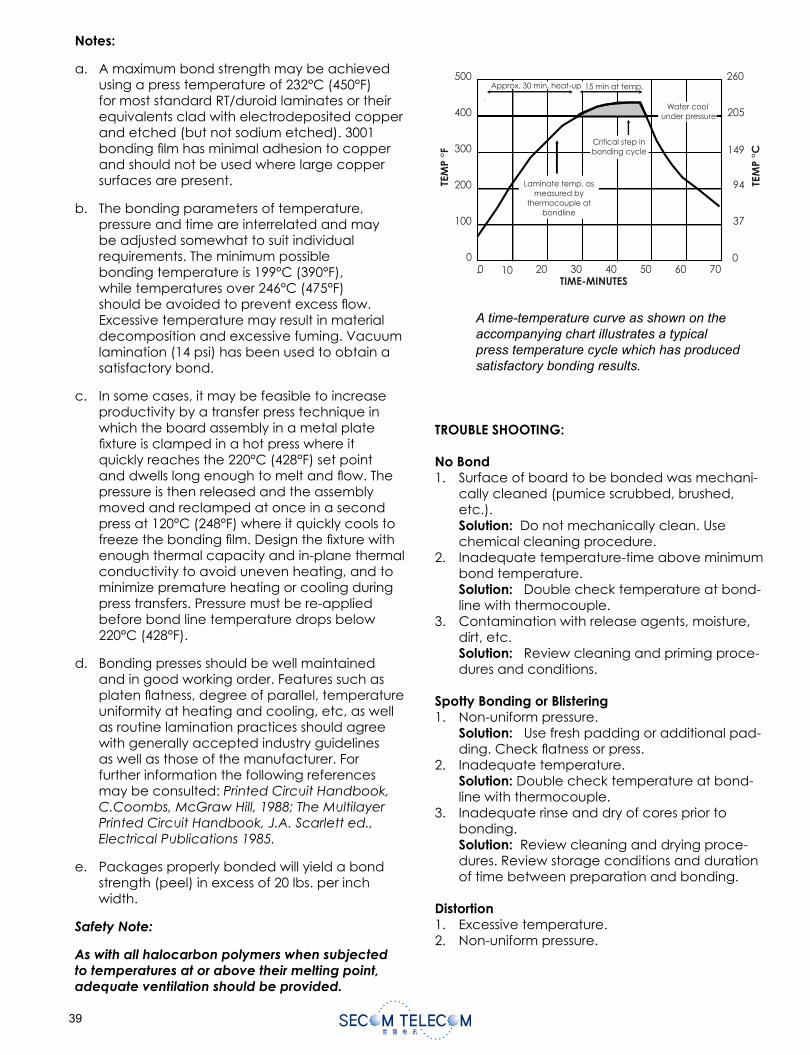
A time-temperature curve as shown on the accompanying chart illustrates a typical press temperature cycle which has produced satisfactory bonding results.
TROUBLE SHOOTING:
No Bond1. Surface of board to be bonded was mechani-
cally cleaned (pumice scrubbed, brushed, etc.).Solution: Do not mechanically clean. Use chemical cleaning procedure.
2. Inadequate temperature-time above minimum bond temperature.Solution: Double check temperature at bond-line with thermocouple.
3. Contamination with release agents, moisture, dirt, etc.Solution: Review cleaning and priming proce-dures and conditions.
Spotty Bonding or Blistering1. Non-uniform pressure.
Solution: Use fresh padding or additional pad-ding. Check fl atness or press.
2. Inadequate temperature.Solution: Double check temperature at bond-line with thermocouple.
3. Inadequate rinse and dry of cores prior to bonding.Solution: Review cleaning and drying proce-dures. Review storage conditions and duration of time between preparation and bonding.
Distortion1. Excessive temperature.2. Non-uniform pressure.
Notes:
a. A maximum bond strength may be achieved using a press temperature of 232°C (450°F) for most standard RT/duroid laminates or their equivalents clad with electrodeposited copper and etched (but not sodium etched). 3001 bonding fi lm has minimal adhesion to copper and should not be used where large copper surfaces are present.
b. The bonding parameters of temperature, pressure and time are interrelated and may be adjusted somewhat to suit individual requirements. The minimum possible bonding temperature is 199°C (390°F), while temperatures over 246°C (475°F) should be avoided to prevent excess fl ow. Excessive temperature may result in material decomposition and excessive fuming. Vacuum lamination (14 psi) has been used to obtain a satisfactory bond.
c. In some cases, it may be feasible to increase productivity by a transfer press technique in which the board assembly in a metal plate fi xture is clamped in a hot press where it quickly reaches the 220°C (428°F) set point and dwells long enough to melt and fl ow. The pressure is then released and the assembly moved and reclamped at once in a second press at 120°C (248°F) where it quickly cools to freeze the bonding fi lm. Design the fi xture with enough thermal capacity and in-plane thermal conductivity to avoid uneven heating, and to minimize premature heating or cooling during press transfers. Pressure must be re-applied before bond line temperature drops below 220°C (428°F).
d. Bonding presses should be well maintained and in good working order. Features such as platen fl atness, degree of parallel, temperature uniformity at heating and cooling, etc, as well as routine lamination practices should agree with generally accepted industry guidelines as well as those of the manufacturer. For further information the following references may be consulted: Printed Circuit Handbook, C.Coombs, McGraw Hill, 1988; The Multilayer Printed Circuit Handbook, J.A. Scarlett ed., Electrical Publications 1985.
e. Packages properly bonded will yield a bond strength (peel) in excess of 20 lbs. per inch width.
Safety Note:
As with all halocarbon polymers when subjected to temperatures at or above their melting point, adequate ventilation should be provided.
500
400
300
200
100
010 20 30 40 50 60 700
Approx. 30 min. heat-up 15 min at temp.
Water cool under pressure
Critical step inbonding cycle
TIME-MINUTES
Laminate temp. asmeasured by
thermocouple atbondline
TEM
P °F
260
205
149
94
37
0
TEM
P °C
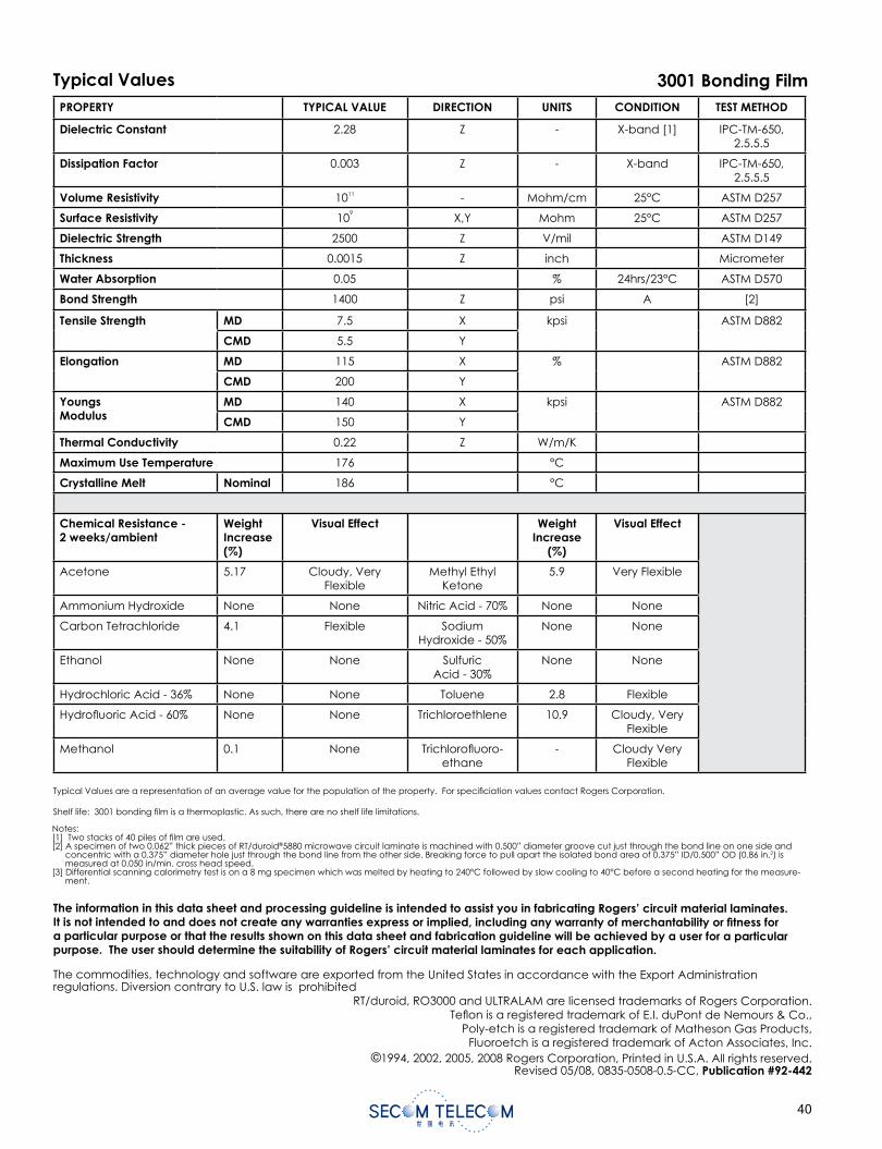
0
A time-temperature curve as shown on the accompanying chart illustrates a typical press temperature cycle which has produced satisfactory bonding results.
TROUBLE SHOOTING:
No Bond1. Surface of board to be bonded was mechani-
cally cleaned (pumice scrubbed, brushed, etc.).Solution: Do not mechanically clean. Use chemical cleaning procedure.
2. Inadequate temperature-time above minimum bond temperature.Solution: Double check temperature at bond-line with thermocouple.
3. Contamination with release agents, moisture, dirt, etc.Solution: Review cleaning and priming proce-dures and conditions.
Spotty Bonding or Blistering1. Non-uniform pressure.
Solution: Use fresh padding or additional pad-ding. Check fl atness or press.
2. Inadequate temperature.Solution: Double check temperature at bond-line with thermocouple.
3. Inadequate rinse and dry of cores prior to bonding.Solution: Review cleaning and drying proce-dures. Review storage conditions and duration of time between preparation and bonding.
Distortion1. Excessive temperature.2. Non-uniform pressure.
Notes:
a. A maximum bond strength may be achieved using a press temperature of 232°C (450°F) for most standard RT/duroid laminates or their equivalents clad with electrodeposited copper and etched (but not sodium etched). 3001 bonding fi lm has minimal adhesion to copper and should not be used where large copper surfaces are present.
b. The bonding parameters of temperature, pressure and time are interrelated and may be adjusted somewhat to suit individual requirements. The minimum possible bonding temperature is 199°C (390°F), while temperatures over 246°C (475°F) should be avoided to prevent excess fl ow. Excessive temperature may result in material decomposition and excessive fuming. Vacuum lamination (14 psi) has been used to obtain a satisfactory bond.
c. In some cases, it may be feasible to increase productivity by a transfer press technique in which the board assembly in a metal plate fi xture is clamped in a hot press where it quickly reaches the 220°C (428°F) set point and dwells long enough to melt and fl ow. The pressure is then released and the assembly moved and reclamped at once in a second press at 120°C (248°F) where it quickly cools to freeze the bonding fi lm. Design the fi xture with enough thermal capacity and in-plane thermal conductivity to avoid uneven heating, and to minimize premature heating or cooling during press transfers. Pressure must be re-applied before bond line temperature drops below 220°C (428°F).
d. Bonding presses should be well maintained and in good working order. Features such as platen fl atness, degree of parallel, temperature uniformity at heating and cooling, etc, as well as routine lamination practices should agree with generally accepted industry guidelines as well as those of the manufacturer. For further information the following references may be consulted: Printed Circuit Handbook, C.Coombs, McGraw Hill, 1988; The Multilayer Printed Circuit Handbook, J.A. Scarlett ed., Electrical Publications 1985.
e. Packages properly bonded will yield a bond strength (peel) in excess of 20 lbs. per inch width.
Safety Note:
As with all halocarbon polymers when subjected to temperatures at or above their melting point, adequate ventilation should be provided.
500
400
300
200
100
010 20 30 40 50 60 700
Approx. 30 min. heat-up 15 min at temp.
Water cool under pressure
Critical step inbonding cycle
TIME-MINUTES
Laminate temp. asmeasured by
thermocouple atbondline
TEM
P °F
260
205
149
94
37
0
TEM
P °C
PROPERTY TYPICAL VALUE DIRECTION UNITS CONDITION TEST METHOD
Dielectric Constant 2.28 Z - X-band [1] IPC-TM-650, 2.5.5.5
Dissipation Factor 0.003 Z - X-band IPC-TM-650, 2.5.5.5
Volume Resistivity 1011 - Mohm/cm 25°C ASTM D257
Surface Resistivity 109
X,Y Mohm 25°C ASTM D257
Dielectric Strength 2500 Z V/mil ASTM D149
Thickness 0.0015 Z inch Micrometer
Water Absorption 0.05 % 24hrs/23°C ASTM D570
Bond Strength 1400 Z psi A [2]
Tensile Strength MD 7.5 X kpsi ASTM D882
CMD 5.5 Y
Elongation MD 115 X % ASTM D882
CMD 200 Y
YoungsModulus
MD 140 X kpsi ASTM D882
CMD 150 Y
Thermal Conductivity 0.22 Z W/m/K
Maximum Use Temperature 176 °C
Crystalline Melt Nominal 186 °C
Chemical Resistance - 2 weeks/ambient
WeightIncrease(%)
Visual Effect Weight Increase
(%)
Visual Effect
Acetone 5.17 Cloudy, Very Flexible
Methyl Ethyl Ketone
5.9 Very Flexible
Ammonium Hydroxide None None Nitric Acid - 70% None None
Carbon Tetrachloride 4.1 Flexible Sodium Hydroxide - 50%
None None
Ethanol None None Sulfuric Acid - 30%
None None
Hydrochloric Acid - 36% None None Toluene 2.8 Flexible
Hydrofl uoric Acid - 60% None None Trichloroethlene 10.9 Cloudy, Very Flexible
Methanol 0.1 None Trichlorofl uoro-ethane
- Cloudy Very Flexible
The information in this data sheet and processing guideline is intended to assist you in fabricating Rogers’ circuit material laminates.It is not intended to and does not create any warranties express or implied, including any warranty of merchantability or fi tness for a particular purpose or that the results shown on this data sheet and fabrication guideline will be achieved by a user for a particularpurpose. The user should determine the suitability of Rogers’ circuit material laminates for each application.
The commodities, technology and software are exported from the United States in accordance with the Export Administration regulations. Diversion contrary to U.S. law is prohibited
RT/duroid, RO3000 and ULTRALAM are licensed trademarks of Rogers Corporation.Tefl on is a registered trademark of E.I. duPont de Nemours & Co.,
Poly-etch is a registered trademark of Matheson Gas Products,Fluoroetch is a registered trademark of Acton Associates, Inc.
©1994, 2002, 2005, 2008 Rogers Corporation, Printed in U.S.A. All rights reserved.Revised 05/08, 0835-0508-0.5-CC, Publication #92-442
Notes:[1] Two stacks of 40 piles of fi lm are used.[2] A specimen of two 0.062” thick pieces of RT/duroid®5880 microwave circuit laminate is machined with 0.500” diameter groove cut just through the bond line on one side and
concentric with a 0.375” diameter hole just through the bond line from the other side. Breaking force to pull apart the isolated bond area of 0.375” ID/0.500” OD (0.86 in.2) is measured at 0.050 in/min. cross head speed.
[3] Differential scanning calorimetry test is on a 8 mg specimen which was melted by heating to 240°C followed by slow cooling to 40°C before a second heating for the measure-ment.
Typical Values are a representation of an average value for the population of the property. For specifi ciation values contact Rogers Corporation.
Shelf life: 3001 bonding fi lm is a thermoplastic. As such, there are no shelf life limitations.
3001 Bonding FilmTypical Values
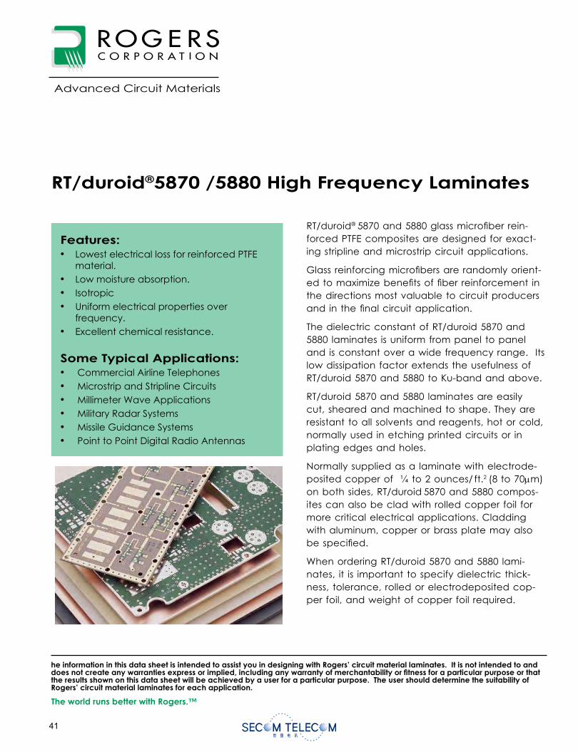
RT/duroid®5870 /5880 High Frequency Laminates
RT/duroid® 5870 and 5880 glass microfi ber rein-forced PTFE composites are designed for exact-ing stripline and mi crostrip circuit applications.
Glass reinforcing microfi bers are randomly orient-ed to maximize benefi ts of fi ber reinforcement in the direc tions most valuable to circuit producers and in the fi nal circuit application.
The dielectric constant of RT/duroid 5870 and 5880 laminates is uniform from panel to panel and is constant over a wide frequency range. Its low dissipation factor extends the usefulness of RT/duroid 5870 and 5880 to Ku-band and above.
RT/duroid 5870 and 5880 laminates are easily cut, sheared and machined to shape. They are resistant to all solvents and reagents, hot or cold, normally used in etching printed circuits or in plating edges and holes.
Normally supplied as a laminate with electrode-posited copper of ¼ to 2 ounces/ ft.2 (8 to 70 m) on both sides, RT/duroid 5870 and 5880 compos-ites can also be clad with rolled copper foil for more critical electrical applications. Cladding with aluminum, copper or brass plate may also be specifi ed.
When ordering RT/duroid 5870 and 5880 lami-nates, it is important to specify dielectric thick-ness, tolerance, rolled or electrodeposited cop-per foil, and weight of copper foil required.
Features:• Lowest electrical loss for reinforced PTFE
material.• Low moisture absorption.• Isotropic• Uniform electrical properties over
frequency.• Excellent chemical resistance.
Some Typical Applications:• Commercial Airline Telephones• Microstrip and Stripline Circuits• Millimeter Wave Applications• Military Radar Systems• Missile Guidance Systems• Point to Point Digital Radio Antennas
Data Sheet1.5000
Advanced Circuit Materials
Advanced Circuit Materials Division100 S. Roosevelt Avenue
Chandler, AZ 85226Tel: 480-961-1382, Fax: 480-961-4533
www.rogerscorporation.com
The world runs better with Rogers.™
he information in this data sheet is intended to assist you in designing with Rogers’ circuit material laminates. It is not intended to and does not create any warranties express or implied, including any warranty of merchantability or fi tness for a particular purpose or that the results shown on this data sheet will be achieved by a user for a particular purpose. The user should determine the suitability of Rogers’ circuit material laminates for each application.
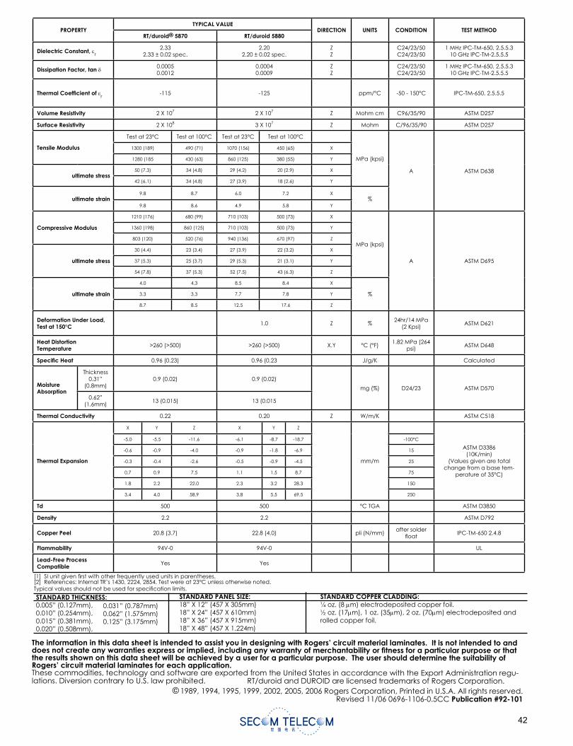
STANDARD THICKNESS:0.005” (0.127mm),0.010” (0.254mm),0.015” (0.381mm),0.020” (0.508mm),
STANDARD PANEL SIZE:18” X 12” (457 X 305mm)18” X 24” (457 X 610mm)18” X 36” (457 X 915mm)18” X 48” (457 X 1.224m)
STANDARD COPPER CLADDING:¼ oz. (8 m) electrodeposited copper foil.½ oz. (17 m), 1 oz. (35 m), 2 oz. (70 m) electrodeposited and rolled copper foil.
The information in this data sheet is intended to assist you in designing with Rogers’ circuit material laminates. It is not intended to and does not create any warranties express or implied, including any warranty of merchantability or fi tness for a particular purpose or that the results shown on this data sheet will be achieved by a user for a particular purpose. The user should determine the suitability of Rogers’ circuit material laminates for each application.These commodities, technology and software are exported from the United States in accordance with the Export Administration regu-lations. Diversion contrary to U.S. law prohibited. RT/duroid and DUROID are licensed trademarks of Rogers Corporation.
© 1989, 1994, 1995, 1999, 2002, 2005, 2006 Rogers Corporation, Printed in U.S.A. All rights reserved.Revised 11/06 0696-1106-0.5CC Publication #92-101
[1] SI unit given fi rst with other frequently used units in parentheses.[2] References: Internal TR’s 1430, 2224, 2854. Test were at 23°C unless otherwise noted. Typical values should not be used for specifi cation limits.
PROPERTYTYPICAL VALUE
DIRECTION UNITS CONDITION TEST METHODRT/duroid® 5870 RT/duroid 5880
Dielectric Constant, r
2.332.33 ± 0.02 spec.
2.202.20 ± 0.02 spec.
ZZ
C24/23/50C24/23/50
1 MHz IPC-TM-650, 2.5.5.310 GHz IPC-TM-2.5.5.5
Dissipation Factor, tan 0.00050.0012
0.00040.0009
ZZ
C24/23/50C24/23/50
1 MHz IPC-TM-650, 2.5.5.310 GHz IPC-TM-2.5.5.5
Thermal Coeffi cient of r
-115 -125 ppm/°C -50 - 150°C IPC-TM-650, 2.5.5.5
Volume Resistivity 2 X 10⁷ 2 X 10⁷ Z Mohm cm C96/35/90 ASTM D257
Surface Resistivity 2 X 10⁸ 3 X 10⁷ Z Mohm C/96/35/90 ASTM D257
Tensile Modulus
Test at 23°C Test at 100°C Test at 23°C Test at 100°C
MPa (kpsi)
A ASTM D638
1300 (189) 490 (71) 1070 (156) 450 (65) X
1280 (185 430 (63) 860 (125) 380 (55) Y
ultimate stress50 (7.3) 34 (4.8) 29 (4.2) 20 (2.9) X
42 (6.1) 34 (4.8) 27 (3.9) 18 (2.6) Y
ultimate strain9.8 8.7 6.0 7.2 X
%9.8 8.6 4.9 5.8 Y
Compressive Modulus
1210 (176) 680 (99) 710 (103) 500 (73) X
MPa (kpsi)
A ASTM D695
1360 (198) 860 (125) 710 (103) 500 (73) Y
803 (120) 520 (76) 940 (136) 670 (97) Z
ultimate stress
30 (4.4) 23 (3.4) 27 (3.9) 22 (3.2) X
37 (5.3) 25 (3.7) 29 (5.3) 21 (3.1) Y
54 (7.8) 37 (5.3) 52 (7.5) 43 (6.3) Z
ultimate strain
4.0 4.3 8.5 8.4 X
%3.3 3.3 7.7 7.8 Y
8.7 8.5 12.5 17.6 Z
Deformation Under Load, Test at 150°C 1.0 Z %
24hr/14 MPa (2 Kpsi)
ASTM D621
Heat Distortion Temperature >260 (>500) >260 (>500) X.Y °C (°F)
1.82 MPa (264 psi)
ASTM D648
Specifi c Heat 0.96 (0.23) 0.96 (0.23 J/g/K Calculated
MoistureAbsorption
Thickness0.31”
(0.8mm)0.9 (0.02) 0.9 (0.02)
mg (%) D24/23 ASTM D570
0.62”(1.6mm)
13 (0.015) 13 (0.015
Thermal Conductivity 0.22 0.20 Z W/m/K ASTM C518
Thermal Expansion
X Y Z X Y Z
mm/m
ASTM D3386(10K/min)
(Values given are total change from a base tem-
perature of 35°C)
-5.0 -5.5 -11.6 -6.1 -8.7 -18.7 -100°C
-0.6 -0.9 -4.0 -0.9 -1.8 -6.9 15
-0.3 -0.4 -2.6 -0.5 -0.9 -4.5 25
0.7 0.9 7.5 1.1 1.5 8.7 75
1.8 2.2 22.0 2.3 3.2 28.3 150
3.4 4.0 58.9 3.8 5.5 69.5 250
Td 500 500 °C TGA ASTM D3850
Density 2.2 2.2 ASTM D792
Copper Peel 20.8 (3.7) 22.8 (4.0) pli (N/mm)after solder
fl oatIPC-TM-650 2.4.8
Flammability 94V-0 94V-0 UL
Lead-Free Process Compatible Yes Yes
0.031” (0.787mm)0.062” (1.575mm)0.125” (3.175mm)
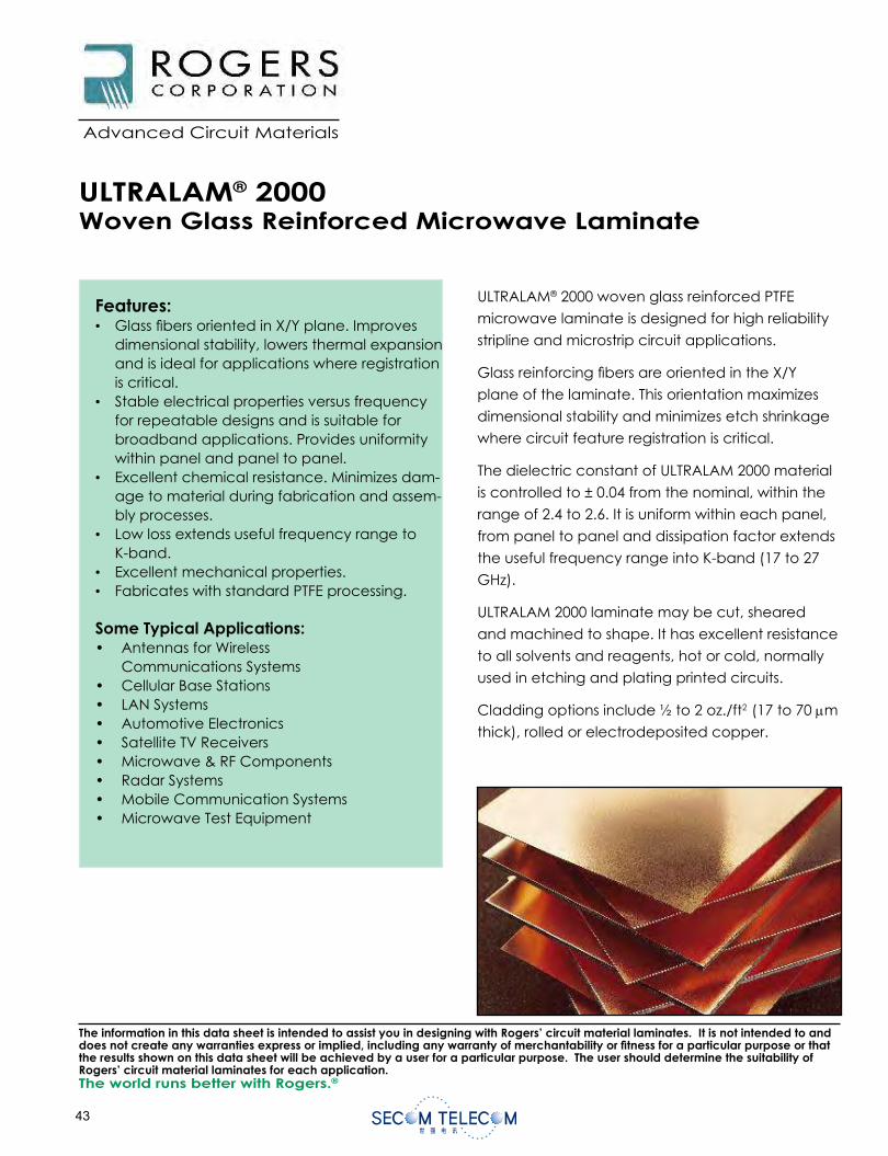
Data Sheet1.2000
The world runs better with Rogers.®
Advanced Circuit Materials
Advanced Circuit Materials100 S. Roosevelt Avenue
Chandler, AZ 85226Tel: 480-961-1382, Fax: 480-961-4533
www.rogerscorporation.com
ULTRALAM® 2000 woven glass reinforced PTFE
microwave laminate is designed for high reliability
stripline and microstrip circuit applications.
Glass reinforcing bers are oriented in the X/Y
plane of the laminate. This orientation maximizes
dimensional stability and minimizes etch shrinkage
where circuit feature registration is critical.
The dielectric constant of ULTRALAM 2000 material
is controlled to ± 0.04 from the nominal, within the
range of 2.4 to 2.6. It is uniform within each panel,
from panel to panel and dissipation factor extends
the useful frequency range into K-band (17 to 27
GHz).
ULTRALAM 2000 laminate may be cut, sheared
and machined to shape. It has excellent resistance
to all solvents and reagents, hot or cold, normally
used in etching and plating printed circuits.
Cladding options include ½ to 2 oz./ft2 (17 to 70 m
thick), rolled or electrodeposited copper.
ULTRALAM® 2000 Woven Glass Reinforced Microwave Laminate
Features:• Glass bers oriented in X/Y plane. Improves
dimensional stability, lowers thermal expansion and is ideal for applications where registration is critical.
• Stable electrical properties versus frequency for repeatable designs and is suitable for broadband applications. Provides uniformity within panel and panel to panel.
• Excellent chemical resistance. Minimizes dam-age to material during fabrication and assem-bly processes.
• Low loss extends useful frequency range to K-band.• Excellent mechanical properties.• Fabricates with standard PTFE processing.
Some Typical Applications:• Antennas for Wireless
Communications Systems• Cellular Base Stations• LAN Systems• Automotive Electronics• Satellite TV Receivers• Microwave & RF Components• Radar Systems• Mobile Communication Systems• Microwave Test Equipment
The information in this data sheet is intended to assist you in designing with Rogers’ circuit material laminates. It is not intended to and does not create any warranties express or implied, including any warranty of merchantability or tness for a particular purpose or that the results shown on this data sheet will be achieved by a user for a particular purpose. The user should determine the suitability of Rogers’ circuit material laminates for each application.
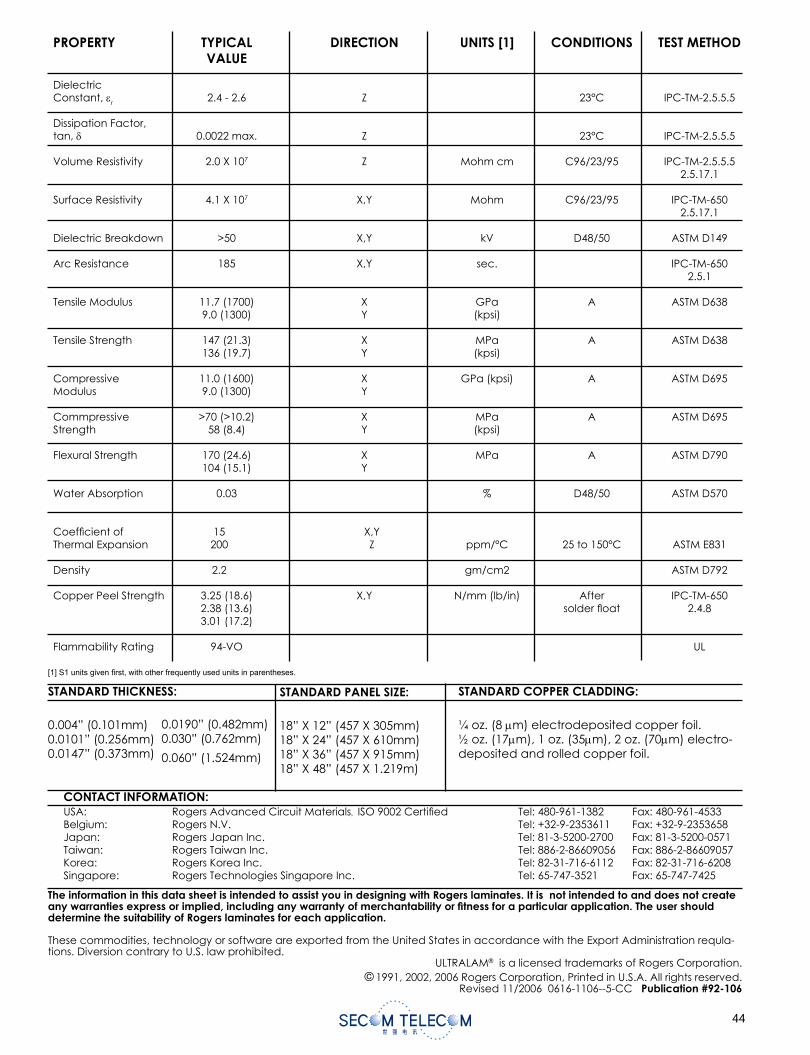
[1] S1 units given rst, with other frequently used units in parentheses.
The information in this data sheet is intended to assist you in designing with Rogers laminates. It is not intended to and does not create any warranties express or implied, including any warranty of merchantability or tness for a particular application. The user should determine the suitability of Rogers laminates for each application.
These commodities, technology or software are exported from the United States in accordance with the Export Administration requla-tions. Diversion contrary to U.S. law prohibited.
ULTRALAM® is a licensed trademarks of Rogers Corporation.© 1991, 2002, 2006 Rogers Corporation, Printed in U.S.A. All rights reserved.
Revised 11/2006 0616-1106--5-CC Publication #92-106
STANDARD THICKNESS:
0.004” (0.101mm)0.0101” (0.256mm)0.0147” (0.373mm)
STANDARD PANEL SIZE:
18” X 12” (457 X 305mm)18” X 24” (457 X 610mm)18” X 36” (457 X 915mm)18” X 48” (457 X 1.219m)
STANDARD COPPER CLADDING:
¼ oz. (8 m) electrodeposited copper foil.½ oz. (17 m), 1 oz. (35 m), 2 oz. (70 m) electro-deposited and rolled copper foil.
CONTACT INFORMATION:USA: Rogers Advanced Circuit Materials, ISO 9002 Certi ed Tel: 480-961-1382 Fax: 480-961-4533Belgium: Rogers N.V. Tel: +32-9-2353611 Fax: +32-9-2353658Japan: Rogers Japan Inc. Tel: 81-3-5200-2700 Fax: 81-3-5200-0571Taiwan: Rogers Taiwan Inc. Tel: 886-2-86609056 Fax: 886-2-86609057Korea: Rogers Korea Inc. Tel: 82-31-716-6112 Fax: 82-31-716-6208Singapore: Rogers Technologies Singapore Inc. Tel: 65-747-3521 Fax: 65-747-7425
0.0190” (0.482mm)0.030” (0.762mm)
0.060” (1.524mm)
PROPERTY TYPICAL DIRECTION UNITS [1] CONDITIONS TEST METHOD VALUE
Dielectric Constant, r 2.4 - 2.6 Z 23°C IPC-TM-2.5.5.5
Dissipation Factor, tan, 0.0022 max. Z 23°C IPC-TM-2.5.5.5
Volume Resistivity 2.0 X 10⁷ Z Mohm cm C96/23/95 IPC-TM-2.5.5.5 2.5.17.1
Surface Resistivity 4.1 X 10⁷ X,Y Mohm C96/23/95 IPC-TM-650 2.5.17.1
Dielectric Breakdown >50 X,Y kV D48/50 ASTM D149
Arc Resistance 185 X,Y sec. IPC-TM-650 2.5.1
Tensile Modulus 11.7 (1700) X GPa A ASTM D638 9.0 (1300) Y (kpsi)
Tensile Strength 147 (21.3) X MPa A ASTM D638 136 (19.7) Y (kpsi)
Compressive 11.0 (1600) X GPa (kpsi) A ASTM D695Modulus 9.0 (1300) Y
Commpressive >70 (>10.2) X MPa A ASTM D695Strength 58 (8.4) Y (kpsi)
Flexural Strength 170 (24.6) X MPa A ASTM D790 104 (15.1) Y
Water Absorption 0.03 % D48/50 ASTM D570
Coef cient of 15 X,Y Thermal Expansion 200 Z ppm/°C 25 to 150°C ASTM E831
Density 2.2 gm/cm2 ASTM D792
Copper Peel Strength 3.25 (18.6) X,Y N/mm (lb/in) After IPC-TM-650 2.38 (13.6) solder oat 2.4.8 3.01 (17.2)
Flammability Rating 94-VO UL
RT/duroid®6002 High Frequency LaminatesRT/duroid® 6002 microwave material is the rst low loss and low dielectric constant laminate to offer superior electrical and mechanical properties essen-tial in designing complex microwave structures which are mechanically reliable and electrically stable.
The thermal coef cient of dielectric constant is extremely low from -55oC to+150oC (-67°F to 302°F) which provides the designers of lters, oscillators and delay lines the electrical stability needed in today’s demanding applications.
A low Z axis coef cient of thermal expansion (CTE) ensures excellent reliability of plated through-holes.RT/duroid 6002 materials have been successfully temperature cycled (-55oC to 125oC [-67°F to 257°F]) for over 5000 cycles without a single via failure.
Excellent dimensional stability (0.2 to 0.5 mils/inch) is achieved by matching the X and Y coef cient of expansion to copper. This often eliminates double etching to achieve tight positional tolerances.
The low tensile modulus (X,Y) greatly reduces the stress applied to solder joints and allows the expan-sion of the laminate to be constrained by a minimum amount of low CTE metal (6 ppm/oC) further increas-ing surface mount reliability.
¼ oz. to 2 oz./ft.2 electrodeposited copper, or ½ oz. to 2 oz/ ft.2 rolled copper foil may be speci ed as cladding on dielectric thicknesses from 0.005” to 0.120” (0.13 to 3.05mm). RT/duroid 6002 laminate is also available clad with aluminum, brass, or copper plates.
Applications particularly suited to the unique prop-erties of RT/duroid 6002 material include at and non-planar structures such as antennas, complex multilayer circuits with interlayer connections, and microwave circuits for aerospace designs in hostile environments. RT/duroid 6002 laminates have Under-writers Laboratories recognition under classi cation 94V-0 (Vertical Flammability Test).
Features:• Low loss for excellent high frequency
performance.• Tight r and thickness contol.• Excellent electrical and mechanical
properties.• Extremely low thermal coef cient of
dielectric constant.• In-plane expansion coef cient matched to
copper.• Low Z-axis expansion.• Low outgassing; Ideal for space
applications.
Some Typical Applications:• Phase Array Antennas• Ground Based and Airborne Radar
Systems• Global Positioning System Antennas• Power Backplanes• High Reliability Complex Multilayer Circuits• Commercial Airline Collision Avoidance
Systems• Beam Forming Networks
Data Sheet1.6002
Advanced Circuit Materials
Advanced Circuit Materials Division100 S. Roosevelt Avenue
Chandler, AZ 85226Tel: 480-961-1382, Fax: 480-961-4533
www.rogerscorporation.com
The world runs better with Rogers.™
The information in this data sheet is intended to assist you in designing with Rogers’ circuit material laminates. It is not intended to and does not create any warranties express or implied, including any warranty of merchantability or tness for a particular purpose or that the results shown on this data sheet will be achieved by a user for a particular purpose. The user should determine the suitability of Rogers’ circuit material laminates for each application.
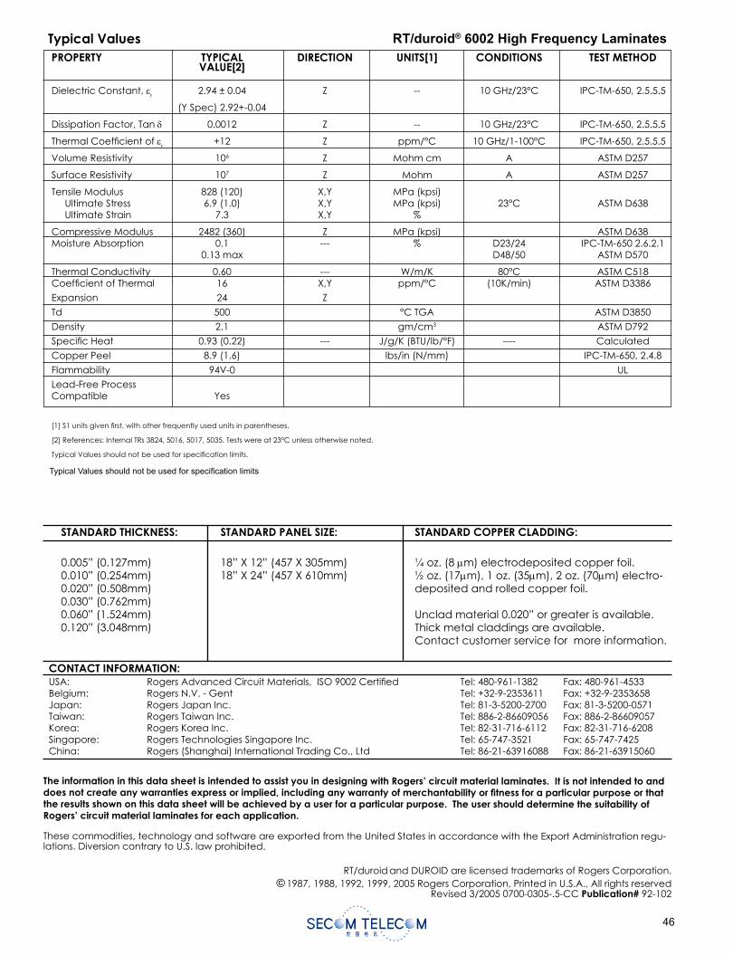
STANDARD THICKNESS:
0.005” (0.127mm)0.010” (0.254mm)0.020” (0.508mm)0.030” (0.762mm)0.060” (1.524mm)0.120” (3.048mm)
STANDARD PANEL SIZE:
18” X 12” (457 X 305mm)18” X 24” (457 X 610mm)
STANDARD COPPER CLADDING:
¼ oz. (8 m) electrodeposited copper foil.½ oz. (17 m), 1 oz. (35 m), 2 oz. (70 m) electro-deposited and rolled copper foil.
Unclad material 0.020” or greater is available.Thick metal claddings are available. Contact customer service for more information.
The information in this data sheet is intended to assist you in designing with Rogers’ circuit material laminates. It is not intended to and does not create any warranties express or implied, including any warranty of merchantability or tness for a particular purpose or that the results shown on this data sheet will be achieved by a user for a particular purpose. The user should determine the suitability ofRogers’ circuit material laminates for each application.
These commodities, technology and software are exported from the United States in accordance with the Export Administration regu-lations. Diversion contrary to U.S. law prohibited.
RT/duroid and DUROID are licensed trademarks of Rogers Corporation.© 1987, 1988, 1992, 1999, 2005 Rogers Corporation, Printed in U.S.A., All rights reserved
Revised 3/2005 0700-0305-.5-CC Publication# 92-102
PROPERTY TYPICAL DIRECTION UNITS[1] CONDITIONS TEST METHOD VALUE[2]
Dielectric Constant, r 2.94 ± 0.04 Z -- 10 GHz/23°C IPC-TM-650, 2.5.5.5
(Y Spec) 2.92+-0.04
Dissipation Factor, Tan 0.0012 Z -- 10 GHz/23°C IPC-TM-650, 2.5.5.5
Thermal Coef cient of r +12 Z ppm/°C 10 GHz/1-100°C IPC-TM-650, 2.5.5.5
Volume Resistivity 106 Z Mohm cm A ASTM D257
Surface Resistivity 107 Z Mohm A ASTM D257
Tensile Modulus 828 (120) X,Y MPa (kpsi) Ultimate Stress 6.9 (1.0) X,Y MPa (kpsi) 23°C ASTM D638 Ultimate Strain 7.3 X,Y %
Compressive Modulus 2482 (360) Z MPa (kpsi) ASTM D638 Moisture Absorption 0.1 --- % D23/24 IPC-TM-650 2.6.2.1 0.13 max D48/50 ASTM D570
Thermal Conductivity 0.60 --- W/m/K 80°C ASTM C518Coef cient of Thermal 16 X,Y ppm/°C (10K/min) ASTM D3386
Expansion 24 Z
Td 500 °C TGA ASTM D3850
Density 2.1 gm/cm3 ASTM D792
Speci c Heat 0.93 (0.22) --- J/g/K (BTU/lb/°F) ---- Calculated
Copper Peel 8.9 (1.6) lbs/in (N/mm) IPC-TM-650, 2.4.8
Flammability 94V-0 UL
Lead-Free ProcessCompatible Yes
[1] S1 units given rst, with other frequently used units in parentheses.
[2] References: Internal TRs 3824, 5016, 5017, 5035. Tests were at 23°C unless otherwise noted.
Typical Values should not be used for speci cation limits.
Typical Values RT/duroid® 6002 High Frequency Laminates
CONTACT INFORMATION:USA: Rogers Advanced Circuit Materials, ISO 9002 Certi ed Tel: 480-961-1382 Fax: 480-961-4533Belgium: Rogers N.V. - Gent Tel: +32-9-2353611 Fax: +32-9-2353658Japan: Rogers Japan Inc. Tel: 81-3-5200-2700 Fax: 81-3-5200-0571Taiwan: Rogers Taiwan Inc. Tel: 886-2-86609056 Fax: 886-2-86609057Korea: Rogers Korea Inc. Tel: 82-31-716-6112 Fax: 82-31-716-6208Singapore: Rogers Technologies Singapore Inc. Tel: 65-747-3521 Fax: 65-747-7425China: Rogers (Shanghai) International Trading Co., Ltd Tel: 86-21-63916088 Fax: 86-21-63915060
Typical Values should not be used for speci cation limits
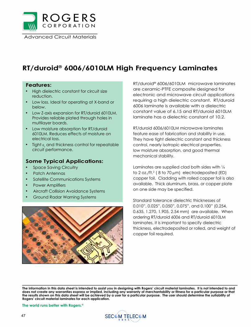
RT/duroid® 6006/6010LM High Frequency Laminates
RT/duroid® 6006/6010LM microwave laminates are ceramic-PTFE composite designed for electronic and microwave circuit applications requiring a high dielectric constant. RT/duroid 6006 laminate is available with a dielectric constant value of 6.15 and RT/duroid 6010LM laminate has a dielectric constant of 10.2.
RT/duroid 6006/6010LM microwave laminates feature ease of fabrication and stability in use.They have tight dielectric constant and thickness control, nearly isotropic electrical properties, low moisture absorption, and good thermal mechanical stability.
Laminates are supplied clad both sides with ¼to 2 oz./ft.2 ( 8 to 70 m) electrodeposited (ED) copper foil. Cladding with rolled copper foil is also available. Thick aluminum, brass, or copper plate on one side may be speci ed.
Standard tolerance dielectric thicknesses of 0.010”, 0.025”, 0.050”, 0.075”, and 0.100” (0.254, 0.635, 1.270, 1.905, 2.54 mm) are available. When ordering RT/duroid 6006 and RT/duroid 6010LMlaminates, it is important to specify dielectric thickness, electrodeposited or rolled, and weight of copper foil required.
Features:• High dielectric constant for circuit size
reduction.• Low loss. Ideal for operating at X-band or
below.• Low Z-axis expansion for RT/duroid 6010LM.
Provides reliable plated through holes in multilayer boards.
• Low moisture absorption for RT/duroid 6010LM. Reduces effects of moisture on electrical loss.
• Tight r and thickness control for repeatable circuit performance.
Some Typical Applications:• Space Saving Circuitry• Patch Antennas• Satellite Communications Systems• Power Ampli ers• Aircraft Collision Avoidance Systems• Ground Radar Warning Systems
Data Sheet1.6000
Advanced Circuit Materials
Advanced Circuit Materials Division100 S. Roosevelt Avenue
Chandler, AZ 85226Tel: 480-961-1382, Fax: 480-961-4533
www.rogerscorporation.com
The world runs better with Rogers.®
The information in this data sheet is intended to assist you in designing with Rogers’ circuit material laminates. It is not intended to and does not create any warranties express or implied, including any warranty of merchantability or tness for a particular purpose or that the results shown on this data sheet will be achieved by a user for a particular purpose. The user should determine the suitability of Rogers’ circuit material laminates for each application.
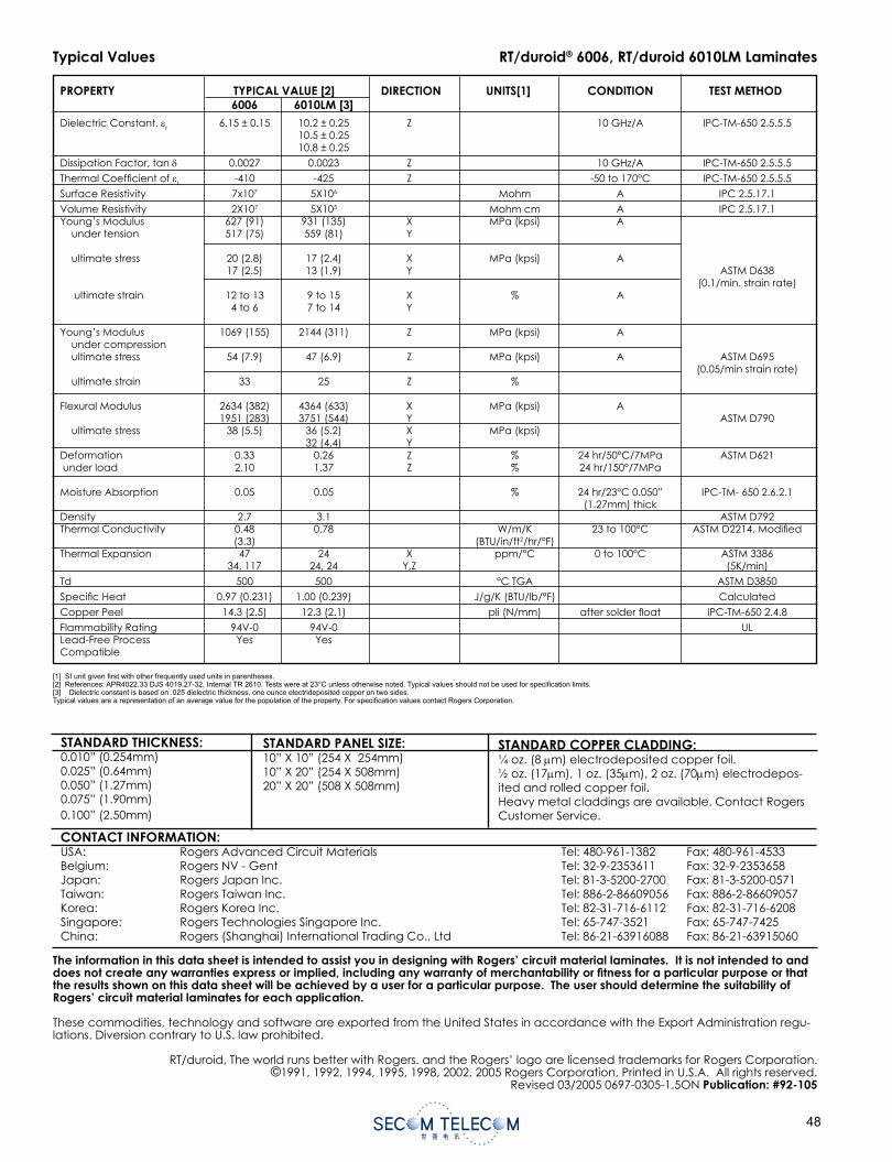
Typical Values
[1] SI unit given rst with other frequently used units in parentheses.[2] References: APR4022.33 DJS 4019.27-32, Internal TR 2610. Tests were at 23°C unless otherwise noted. Typical values should not be used for speci cation limits.[3] Dielectric constant is based on .025 dielectric thickness, one ounce electrideposited copper on two sides.Typical values are a representation of an average value for the population of the property. For speci cation values contact Rogers Corporation.
RT/duroid® 6006, RT/duroid 6010LM Laminates
The information in this data sheet is intended to assist you in designing with Rogers’ circuit material laminates. It is not intended to and does not create any warranties express or implied, including any warranty of merchantability or tness for a particular purpose or that the results shown on this data sheet will be achieved by a user for a particular purpose. The user should determine the suitability of Rogers’ circuit material laminates for each application.
These commodities, technology and software are exported from the United States in accordance with the Export Administration regu-lations. Diversion contrary to U.S. law prohibited.
RT/duroid, The world runs better with Rogers. and the Rogers’ logo are licensed trademarks for Rogers Corporation.©1991, 1992, 1994, 1995, 1998, 2002, 2005 Rogers Corporation, Printed in U.S.A. All rights reserved.
Revised 03/2005 0697-0305-1.5ON Publication: #92-105
STANDARD THICKNESS:0.010” (0.254mm)0.025” (0.64mm)0.050” (1.27mm)0.075” (1.90mm)0.100” (2.50mm)
STANDARD PANEL SIZE:10” X 10” (254 X 254mm)10” X 20” (254 X 508mm)20” X 20” (508 X 508mm)
STANDARD COPPER CLADDING:¼ oz. (8 m) electrodeposited copper foil.½ oz. (17 m), 1 oz. (35 m), 2 oz. (70 m) electrodepos-ited and rolled copper foil.Heavy metal claddings are available. Contact Rogers Customer Service.
CONTACT INFORMATION:USA: Rogers Advanced Circuit Materials Tel: 480-961-1382 Fax: 480-961-4533Belgium: Rogers NV - Gent Tel: 32-9-2353611 Fax: 32-9-2353658Japan: Rogers Japan Inc. Tel: 81-3-5200-2700 Fax: 81-3-5200-0571Taiwan: Rogers Taiwan Inc. Tel: 886-2-86609056 Fax: 886-2-86609057Korea: Rogers Korea Inc. Tel: 82-31-716-6112 Fax: 82-31-716-6208Singapore: Rogers Technologies Singapore Inc. Tel: 65-747-3521 Fax: 65-747-7425China: Rogers (Shanghai) International Trading Co., Ltd Tel: 86-21-63916088 Fax: 86-21-63915060
PROPERTY TYPICAL VALUE [2] DIRECTION UNITS[1] CONDITION TEST METHOD 6006 6010LM [3]
Dielectric Constant, r 6.15 ± 0.15 10.2 ± 0.25 Z 10 GHz/A IPC-TM-650 2.5.5.5 10.5 ± 0.25 10.8 ± 0.25
Dissipation Factor, tan 0.0027 0.0023 Z 10 GHz/A IPC-TM-650 2.5.5.5
Thermal Coef cient of r -410 -425 Z -50 to 170°C IPC-TM-650 2.5.5.5
Surface Resistivity 7x10⁷ 5X10⁶ Mohm A IPC 2.5.17.1
Volume Resistivity 2X10⁷ 5X10⁵ Mohm cm A IPC 2.5.17.1Young’s Modulus 627 (91) 931 (135) X MPa (kpsi) A under tension 517 (75) 559 (81) Y
ultimate stress 20 (2.8) 17 (2.4) X MPa (kpsi) A 17 (2.5) 13 (1.9) Y ASTM D638 (0.1/min. strain rate) ultimate strain 12 to 13 9 to 15 X % A 4 to 6 7 to 14 Y
Young’s Modulus 1069 (155) 2144 (311) Z MPa (kpsi) A under compression ultimate stress 54 (7.9) 47 (6.9) Z MPa (kpsi) A ASTM D695 (0.05/min strain rate) ultimate strain 33 25 Z %
Flexural Modulus 2634 (382) 4364 (633) X MPa (kpsi) A 1951 (283) 3751 (544) Y ASTM D790 ultimate stress 38 (5.5) 36 (5.2) X MPa (kpsi) 32 (4.4) Y Deformation 0.33 0.26 Z % 24 hr/50°C/7MPa ASTM D621 under load 2.10 1.37 Z % 24 hr/150°/7MPa
Moisture Absorption 0.05 0.05 % 24 hr/23°C 0.050” IPC-TM- 650 2.6.2.1 (1.27mm) thick Density 2.7 3.1 ASTM D792Thermal Conductivity 0.48 0.78 W/m/K 23 to 100°C ASTM D2214, Modi ed (3.3) (BTU/in/ft2/hr/°F)Thermal Expansion 47 24 X ppm/°C 0 to 100°C ASTM 3386 34, 117 24, 24 Y,Z (5K/min)
Td 500 500 °C TGA ASTM D3850
Speci c Heat 0.97 (0.231) 1.00 (0.239) J/g/K (BTU/lb/°F) Calculated
Copper Peel 14.3 (2.5) 12.3 (2.1) pli (N/mm) after solder oat IPC-TM-650 2.4.8
Flammability Rating 94V-0 94V-0 ULLead-Free Process Yes Yes Compatible
TMM® thermoset microwave materials are ceramic
thermoset polymer composites designed for high plated-
thru-hole reliability stripline and microstrip applications.
TMM laminates are available in a wide range of dielectric
constants and claddings.
The electrical and mechanical properties of TMM
laminates combine many of the benefi ts of both ceramic
and traditional PTFE microwave circuit laminates, without
requiring the specialized production techniques common
to these materials. TMM laminates do not require a sodium
napthanate treatment prior to electroless plating.
TMM laminates have an exceptionally low thermal
coeffi cient of dielectric constant, typically less than 30
ppm/°C. The material's isotropic coeffi cients of thermal
expansion, very closely matched to copper, allow for
production of high reliability plated through holes, and
low etch shrinkage values. Furthermore, the thermal
conductivity of TMM laminates is approximately twice that
of traditional PTFE/ceramic laminates, facilitating heat
removal.
TMM laminates are based on thermoset resins, and do
not soften when heated. As a result, wire bonding of
component leads to circuit traces can be performed
without concerns of pad lifting or substrate deformation.
TMM laminates combine many of the desirable features
of ceramic substrates with the ease of soft substrate
processing techniques. TMM laminates are available clad
with 1/2 oz/ft2 to 2 oz/ ft2 electrodeposited copper foil, or
bonded directly to brass or aluminum plates. Substrate
thicknesses of 0.015" to 0.500" and greater are available.
The base substrate is resistant to etchants and solvents
used in printed circuit production. Consequently, all
common PWB processes can be used to produce TMM
thermoset microwave materials.
TMM® Thermoset Microwave Materials
Data SheetTMM
Advanced Circuit Materials
Advanced Circuit Materials Division100 S. Roosevelt Avenue
Chandler, AZ 85226Tel: 480-961-1382, Fax: 480-961-4533
www.rogerscorporation.com
Features:• Wide range of dielectric constants. Ideal for
single material systems on a wide variety of ap-plications.
• Excellent mechanical properties. Resists creep and cold fl ow.
• Exceptionally low thermal coeffi cient of dielec-tric constant.
• Coeffi cient of thermal expansion matched to copper. High reliability of plated through holes.
• Resistant to process chemicals. No damage to material during fabrication and assembly processes.
• Thermoset resin for reliable wirebonding. No specialized production techniques required. TMM 10 and 10i laminates can replace alumina substrates.
Some Typical Applications:• RF and Microwave Circuitry• Global Positioning Systems Antennas• Power Amplifi ers and Combiners• Patch Antennas• Filters and Coupler• Dielectric Polarizers and Lenses• Satellite Communication Systems• Chip Testers
The world runs better with Rogers.®
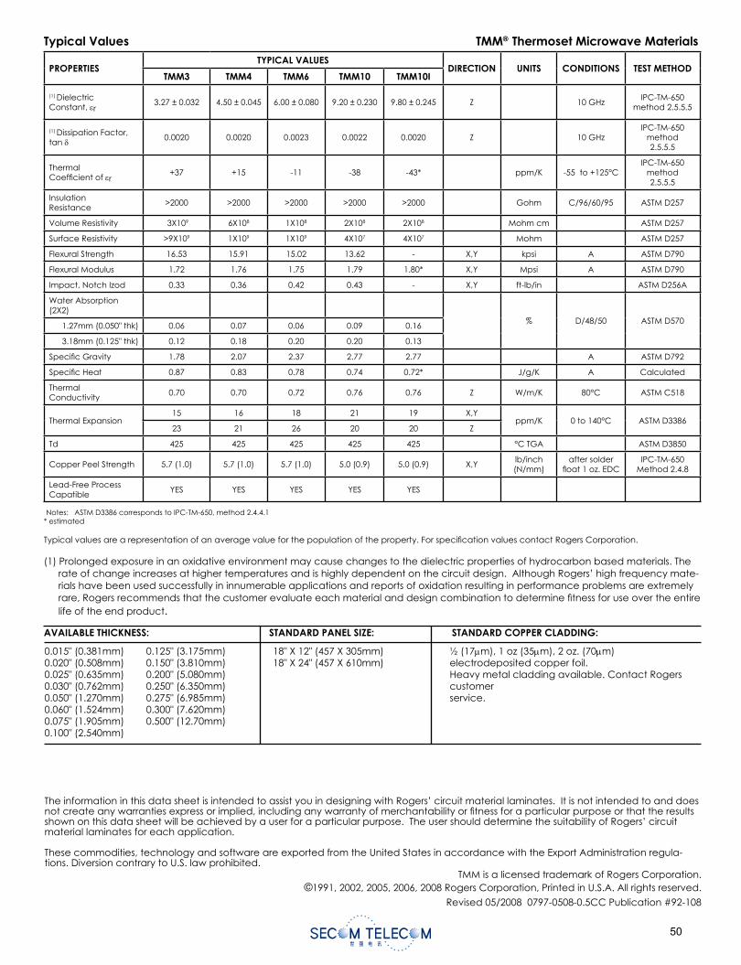
0
TMM® thermoset microwave materials are ceramic
thermoset polymer composites designed for high plated-
thru-hole reliability stripline and microstrip applications.
TMM laminates are available in a wide range of dielectric
constants and claddings.
The electrical and mechanical properties of TMM
laminates combine many of the benefi ts of both ceramic
and traditional PTFE microwave circuit laminates, without
requiring the specialized production techniques common
to these materials. TMM laminates do not require a sodium
napthanate treatment prior to electroless plating.
TMM laminates have an exceptionally low thermal
coeffi cient of dielectric constant, typically less than 30
ppm/°C. The material's isotropic coeffi cients of thermal
expansion, very closely matched to copper, allow for
production of high reliability plated through holes, and
low etch shrinkage values. Furthermore, the thermal
conductivity of TMM laminates is approximately twice that
of traditional PTFE/ceramic laminates, facilitating heat
removal.
TMM laminates are based on thermoset resins, and do
not soften when heated. As a result, wire bonding of
component leads to circuit traces can be performed
without concerns of pad lifting or substrate deformation.
TMM laminates combine many of the desirable features
of ceramic substrates with the ease of soft substrate
processing techniques. TMM laminates are available clad
with 1/2 oz/ft2 to 2 oz/ ft2 electrodeposited copper foil, or
bonded directly to brass or aluminum plates. Substrate
thicknesses of 0.015" to 0.500" and greater are available.
The base substrate is resistant to etchants and solvents
used in printed circuit production. Consequently, all
common PWB processes can be used to produce TMM
thermoset microwave materials.
TMM® Thermoset Microwave Materials
Data SheetTMM
Advanced Circuit Materials
Advanced Circuit Materials Division100 S. Roosevelt Avenue
Chandler, AZ 85226Tel: 480-961-1382, Fax: 480-961-4533
www.rogerscorporation.com
Features:• Wide range of dielectric constants. Ideal for
single material systems on a wide variety of ap-plications.
• Excellent mechanical properties. Resists creep and cold fl ow.
• Exceptionally low thermal coeffi cient of dielec-tric constant.
• Coeffi cient of thermal expansion matched to copper. High reliability of plated through holes.
• Resistant to process chemicals. No damage to material during fabrication and assembly processes.
• Thermoset resin for reliable wirebonding. No specialized production techniques required. TMM 10 and 10i laminates can replace alumina substrates.
Some Typical Applications:• RF and Microwave Circuitry• Global Positioning Systems Antennas• Power Amplifi ers and Combiners• Patch Antennas• Filters and Coupler• Dielectric Polarizers and Lenses• Satellite Communication Systems• Chip Testers
The world runs better with Rogers.®
AVAILABLE THICKNESS: STANDARD PANEL SIZE: STANDARD COPPER CLADDING:
0.015" (0.381mm)0.020" (0.508mm)0.025" (0.635mm)0.030" (0.762mm)0.050" (1.270mm)0.060" (1.524mm)0.075" (1.905mm)0.100" (2.540mm)
0.125" (3.175mm)0.150" (3.810mm)0.200" (5.080mm)0.250" (6.350mm)0.275" (6.985mm)0.300" (7.620mm)0.500" (12.70mm)
18" X 12" (457 X 305mm)18" X 24" (457 X 610mm)
½ (17 m), 1 oz (35 m), 2 oz. (70 m)electrodeposited copper foil.Heavy metal cladding available. Contact Rogers customerservice.
The information in this data sheet is intended to assist you in designing with Rogers’ circuit material laminates. It is not intended to and does not create any warranties express or implied, including any warranty of merchantability or fi tness for a particular purpose or that the results shown on this data sheet will be achieved by a user for a particular purpose. The user should determine the suitability of Rogers’ circuit material laminates for each application.
These commodities, technology and software are exported from the United States in accordance with the Export Administration regula-tions. Diversion contrary to U.S. law prohibited.
TMM is a licensed trademark of Rogers Corporation.©1991, 2002, 2005, 2006, 2008 Rogers Corporation, Printed in U.S.A. All rights reserved.
Revised 05/2008 0797-0508-0.5CC Publication #92-108
Typical Values TMM® Thermoset Microwave Materials
PROPERTIESTYPICAL VALUES
DIRECTION UNITS CONDITIONS TEST METHODTMM3 TMM4 TMM6 TMM10 TMM10I
(1) DielectricConstant, r
3.27 ± 0.032 4.50 ± 0.045 6.00 ± 0.080 9.20 ± 0.230 9.80 ± 0.245 Z 10 GHzIPC-TM-650
method 2.5.5.5
(1) Dissipation Factor, tan
0.0020 0.0020 0.0023 0.0022 0.0020 Z 10 GHzIPC-TM-650
method2.5.5.5
ThermalCoeffi cient of r
+37 +15 -11 -38 -43* ppm/K -55 to +125°CIPC-TM-650
method2.5.5.5
InsulationResistance
>2000 >2000 >2000 >2000 >2000 Gohm C/96/60/95 ASTM D257
Volume Resistivity 3X10⁹ 6X10⁸ 1X10⁸ 2X10⁸ 2X10⁸ Mohm cm ASTM D257
Surface Resistivity >9X10⁹ 1X10⁹ 1X10⁹ 4X10⁷ 4X10⁷ Mohm ASTM D257
Flexural Strength 16.53 15.91 15.02 13.62 - X,Y kpsi A ASTM D790
Flexural Modulus 1.72 1.76 1.75 1.79 1.80* X,Y Mpsi A ASTM D790
Impact, Notch Izod 0.33 0.36 0.42 0.43 - X,Y ft-lb/in ASTM D256A
Water Absorption(2X2)
% D/48/50 ASTM D5701.27mm (0.050" thk) 0.06 0.07 0.06 0.09 0.16
3.18mm (0.125" thk) 0.12 0.18 0.20 0.20 0.13
Specifi c Gravity 1.78 2.07 2.37 2.77 2.77 A ASTM D792
Specifi c Heat 0.87 0.83 0.78 0.74 0.72* J/g/K A Calculated
ThermalConductivity
0.70 0.70 0.72 0.76 0.76 Z W/m/K 80°C ASTM C518
Thermal Expansion15 16 18 21 19 X,Y
ppm/K 0 to 140°C ASTM D338623 21 26 20 20 Z
Td 425 425 425 425 425 °C TGA ASTM D3850
Copper Peel Strength 5.7 (1.0) 5.7 (1.0) 5.7 (1.0) 5.0 (0.9) 5.0 (0.9) X,Ylb/inch(N/mm)
after solderfl oat 1 oz. EDC
IPC-TM-650Method 2.4.8
Lead-Free ProcessCapatible
YES YES YES YES YES
Notes: ASTM D3386 corresponds to IPC-TM-650, method 2.4.4.1* estimated
Typical values are a representation of an average value for the population of the property. For specifi cation values contact Rogers Corporation.
(1) Prolonged exposure in an oxidative environment may cause changes to the dielectric properties of hydrocarbon based materials. The rate of change increases at higher temperatures and is highly dependent on the circuit design. Although Rogers’ high frequency mate-rials have been used successfully in innumerable applications and reports of oxidation resulting in performance problems are extremelyrare, Rogers recommends that the customer evaluate each material and design combination to determine fi tness for use over the entire life of the end product.
S01001V04世强电讯 2010年3月 印
深圳世强电讯有限公司 SHENZHEN SECOM TELECOM CO., LTD.深圳市人民南路3005号深房广场A座32楼 邮编:51800132/F., Block A, Shenfang Plaza, No. 3005 Renmin Nan Rd., Shenzhen 518001, P.R.C.Tel: +86-755-25155888 25155887 Fax: +86-755-25155880 25155881 25165635
上海办事处 SHANGHAI OFFICE上海市定西路1100号辽油大厦5楼D座 邮编:200050Block D, 5/F., Liaoyou Mansion, No. 1100 Dingxi Rd., Shanghai 200050, P.R.C.Tel: +86-21-52371820 Fax: +86-21-32120694
杭州办事处 HANGZHOU OFFICE杭州市德胜路385号银都大厦1110室 邮编:310005Rm. 1110, No.385 Desheng Rd., Hangzhou 310005, P.R.C.Tel: +86-571-88398810 Fax: +86-571-88398825
成都办事处 CHENGDU OFFICE成都市新华大道文武路42号新时代广场11楼G单元 邮编:610017Unit G, 11/F., New Times Plaza, No. 42 Wenwu Rd., Xinhua Avenue, Chengdu. 610017, P.R.C.Tel: +86-28-82981751 82981752 Fax: +86-28-82981753
武汉办事处 WUHAN OFFICE武汉市武昌中南路7号中商广场A座2004室 邮编:430071Rm. 2004, Block A, Zhongshang Plaza, No. 7 Zhongnan Rd., Wuchang, Wuhan 430071, P.R.C. Tel: +86-27-87322726 Fax: +86-27-87322920
西安办事处 XI’AN OFFICE西安办事处 XI’AN OFFICE西安市高新开发区高新路48号火炬大厦705D室 邮编:710075Rm. 705D, Huoju Bldg., No. 48 Gaoxin Rd., National Hi-tech Industrial Development Zone, Xi'an 710075, P.R.C. Tel: +86-29-88323435 88327570 Fax: +86-29-88323331
苏州办事处 SUZHOU OFFICE苏州办事处 SUZHOU OFFICE苏州市平江区娄门路266号平江创意街区9栋205室 邮编:215000Rm.205, creative block 9, No.266 Loumen Rd., Pingjiang District, Suzhou 215000, P.R.C.Tel: +86-512-69351315 Fax: +86-512-69351319
沈阳办事处 SHENYANG OFFICE沈阳市和平区三好街55号沈阳信息产业大厦708室 邮编:110004Rm.708, Information Industry Bldg., No.55 Sanhao street, Heping District, Shenyang 110004, P.R.C.Tel: +86-24-23988556 Fax: +86-24-23988557
世强科技(香港)有限公司 SECOM TECHNOLOGIES (HONGKONG) LTD.香港观塘开源道62号骆驼漆大厦1期11楼A,B室Rm. A & B, 11/F, Block 1 of Camelpaint Building, NO. 62 Hoi Yuen Rd., KLN. HK.Tel: +852-26249917 Fax: +852-26249937
南京办事处 NANJING OFFICE南京市中山东路147号大行宫大厦1206室 邮编:210002Rm. 1206, Daxinggong Mansion, No.147 East Zhongshan Rd., Nanjing 210002, P.R.C. Tel: +86-25-84552900 84552911 Fax: +86-25-84552922
北京办事处 BEIJING OFFICE北京市海淀区知春路1号学院国际大厦603 邮编:100083Rm. 603, Xuanyuan International Plaza, No.1 Zhichun Rd. Haidian District, Beijing 100083, P.R.C.Tel: +86-10-82336866 Fax: +86-10-82336966
青岛办事处 QINGDAO OFFICE青岛市市南区香港中路77号香岛大厦610室 邮编:266071Rm. 610 Xiangdao Masion NO.77 Hongkong Central Road Shinan District Qingdao 266071, P.R.C.Tel: +86-532-85899132 Fax: +86-532-85899273
厦门办事处 XIAMEN OFFICE厦门市湖滨北路莲滨里36号水岸筼筜B栋702室 邮编:361012Rm. 702, Brink Yundang B, NO.36 Lianbinli, Hubin north road, xiamen 361012, P.R.C.Tel: +86-592-5806950 Fax: +86-592-5806951