Embed Size (px)
Citation preview

REF. NUMBER AND DATE SHOULD BE QUOTED IN REFERENCE TO THIS LETTER 凡 提 及 本 信 時 請 引 述 編 號 及 日 期
FSD Circular Letter No. 1/2015
消 防 處 牌 照 及 審 批 總 區
香港九龍尖沙咀東部康莊道一號 消防總部大廈五樓
本處檔號 Our Ref.: (13) in FP(LC) 314/07 Pt. 7 來函檔號 Your Ref.:
圖文傳真 Fax: 852 - 2723 2197 電 話 Tel. No.: 852 - 2733 7612 電 郵 Email : [email protected]
FIRE SERVICES DEPARTMENT LICENSING AND CERTIFICATION COMMAND
5/F, Fire Services Headquarters Building,
No.1 Hong Chong Road, Tsim Sha Tsui East, Kowloon,
Hong Kong
10 March 2015 To: Recipients of FSD Circular Letters
Dear Sirs/Madams,
FSD Circular Letter No. 1/2015
Documents Required for Application for Compliance Inspection of
Fire Service Installations and Equipment
This Circular Letter summarizes the documents required for application for compliance inspection of fire service installations (FSI) and equipment installed at the development/building as delineated in the approved building plans. The target time for arranging a compliance inspection remains 15 working days upon receipt of the documents as listed below:
Form FSI/501 The Authorized Person (AP) and Registered Fire Service Installation Contractor (RFSIC) shall submit a duly completed form “FSI/501 - Application for Inspection and Testing of Fire Service Installations and Equipment” to the Director of Fire Services for request of initial FSI compliance inspection. The form FSI/501 can be downloaded from FSD website: http://www.hkfsd.gov.hk/eng/download1.html. Form FSI/314 The AP and RFSIC shall submit a duly completed form FSI/314 together with the following documents/drawings according to the Stage 2 submission procedures as stipulated in FSD Circular Letter No. 1/2005:
(a) Two sets of as-fitted FSI layout plans as prepared according to Part I of FSD
Circular Letter 4/96 (one set of the drawings shall be coloured); and
(b) A schedule of the submitted FSI layout plans.
/2…

REF. NUMBER AND DATE SHOULD BE QUOTED IN REFERENCE TO THIS LETTER 凡 提 及 本 信 時 請 引 述 編 號 及 日 期
FSD Circular Letter No. 1/2015
– 2 –
As FSI plans for smoke control systems including smoke extraction systems, staircase pressurization systems and ventilation/air-conditioning control systems shall be submitted to FSD for prior vetting, these drawings are not required to be submitted together with the form FSI/314. The form FSI/314 can be downloaded from FSD website: http://www.hkfsd.gov.hk/eng/download1.html.
Testing and Commissioning Checklists The following testing and commissioning checklists for fire service installations and equipment as appended in Appendices 1 to 7 of this letter will replace seven checklists as in Appendices 1 to 7 of “Codes of Practice for Minimum Fire Service Installations and Equipment and Inspection, Testing and Maintenance of Installations and Equipment (April 2012)” (FSD COPs): (a) Appendix 1 - Testing and Commissioning Checklist for Actuating Devices and
Operation of Fire Shutter
(b) Appendix 2 - Testing and Commissioning Checklist for CO2/Clean Agent Extinguishing System
(c) Appendix 3 - Testing and Commissioning Checklist for Emergency Generator Installation
(d) Appendix 4 - Testing and Commissioning Checklist for Fire Detection and Fire Alarm System
(e) Appendix 5 - Testing and Commissioning Checklist for Fire Hydrant and Hose Reel Installation
(f) Appendix 6 - Testing and Commissioning Checklist for Staircase Pressurization System
(g) Appendix 7 - Testing and Commissioning Checklist for Street Fire Hydrant System
The RFSIC shall submit duly completed testing and commissioning checklists for FSIs to FSD before the inspection. Fire Service Installations – Equipment List The revised “Fire Service Installations – Equipment List” (Equipment List) which will replace Annex I of FSD Circular Letter No. 1/2007 is appended in Appendix 8 of this letter. To facilitate the compliance inspection, the RFSIC shall submit to FSD the duly completed Equipment List with his signature on each page together with the following supporting documents and documentary proof if applicable: (a) Listing certificates/ records/ documents/ printouts from product certification
bodies;
/3…

REF. NUMBER AND DATE SHOULD BE QUOTED IN REFERENCE TO THIS LETTER 凡 提 及 本 信 時 請 引 述 編 號 及 日 期
FSD Circular Letter No. 1/2015
– 3 –
(b) FSD approval/ acceptance letters;
(c) Test certificates/ data sheets/ catalogues/ calculations; and
(d) Other necessary technical information.
The APs and RFSICs should bear in mind that the request for initial inspection on
FSIs may be rejected by FSD if they failed to submit the above documents, or they are incomplete or contain significant irregularities.
This Circular Letter will take effect on 9 June 2015.
Encl.
Yours faithfully,
(Robert LAU)
for Director of Fire Services

APPENDIX 1
Testing and Commissioning Checklist for Actuating Devices and Operation of Fire Shutter
I. REFERENCE
Project ………………………………………. FSD Ref. …………………..………...…………….
Address …………………...………………… Location …………………….…………..…………
……………………………………………… ……………………………………………………..
LPC Ref. …………………………………… Maker’s Name ………………...…………………..
II. TYPE
Single Steel Rolling Shutter [ ]
Double Steel Rolling Shutter [ ]
Push-up Type with Lifting Handle [ ]
Sliding Shutter [ ]
With Mechanical Gearing [ ]
III. INSTALLATION Yes No Remarks
3.1 Where automatic self-closing devices are fitted, do they cause no interference to the manual opening and closing of the shutter? [ ] [ ] ………………………… 3.2 Where smoke detectors are provided for the actuation of the shutter, are they fitted to both sides of the wall opening? [ ] [ ] …………………………
3.3 Are smoke detectors installed as far as practicable
to the provisions of the BS 5839-1:2002+A2:2008? [ ] [ ] …………………………
3.4 Is permanent nameplate with adequate information provided? [ ] [ ] ………………………… 3.5 Are manual controls provided to both sides of the wall opening? [ ] [ ] …………………………
IV. SHUTTER OPERATION
4.1 Does the automatic actuation device function satisfactorily? [ ] [ ] …………………………
4.2 Is secondary source of electricity supply
provided? [ ] [ ] …………………………
4.3 Is the descending speed* of the shutter
acceptable? [ ] [ ] …………………………
* Descending time shall be within 15-60 seconds for shutters in openings in excess of 2.5 m in height; not faster than 8 seconds for other shutters in openings of height within 2.5 m and that the bottom rail of the shutter shall reach the mid-height in not less than half the total descending time of the shutter.
Page 1
APPENDIX 1
V. GENERAL COMMENTS & REMARKS
Test conducted by: ………………………………….….. (Signature) ……………………………………… Name of FSI Contractor’s Representative (in block letters) ……………………………………… Company Chop ………………………………………. (RC / ) Name of FSI Contractor (FSI Contractor Registration Number) Date ………………………………………………
Page 2

APPENDIX 2
Testing and Commissioning Checklist for CO2/Clean Agent Extinguishing System
I. REFERENCE
Project ............................................................. FSD Ref. ......................................................
Address ........................................................... Location/Room ............................................
......................................................................... ......................................................................
Working/Design Drawing Ref. ….................................................. Yes No N/A
Is drawing enclosed? [ ] [ ] [ ]
Approved Computer Program Ref. ................................................
Is program enclosed? [ ] [ ] [ ]
Is catalogue enclosed? [ ] [ ] [ ]
Is certification for pneumatic test to pipings enclosed? [ ] [ ] [ ]
II. TYPE OF SYSTEM
CO2 FM200 Others*
[ ] [ ] [ ]
Total Flooding [ ] Local Application [ ] *Please specify
Modular [ ] Cylinder [ ]
Pre-engineered [ ] Engineered [ ] ...................................
High Pressure [ ] Low Pressure [ ]
Single Hazard [ ] Multiple Hazard [ ] Primary Bank Only [ ] With Reserve Bank [ ] III. PROTECTED AREA
Yes No Remarks
3.1 Does occupancy tally with approved building plans? [ ] [ ] ...................................
3.2 Does compartmentation of protected premises tally with approved building plans? [ ] [ ] ...................................
3.3 Does general layout tally with FSI drawings? [ ] [ ] ...................................
3.4 Are openings properly sealed or closable automatically during/before agent discharge? [ ] [ ] ...................................
3.5 Are warning/instruction signs provided at entrance to; and in the case of normally occupied premises, inside the protected area? [ ] [ ] ...................................
3.6 Does the following components:— Tally with If not, whether the as-fitted drawings? location/position acceptable?
Yes No Yes No Remarks
3.6.1 Audio Alarm—Bell/Buzzer etc. [ ] [ ] [ ] [ ] ................................
3.6.2 Visual Alarm—Light/Strobe etc. [ ] [ ] [ ] [ ] ................................
3.6.3 Detector [ ] [ ] [ ] [ ] ................................
3.6.4 Manual Release [ ] [ ] [ ] [ ] ................................
Tally with
drawings? If not, whether the as-fitted location/position acceptable?
Yes No Yes No Remarks
Page 1

APPENDIX 2 3.6.5 Piping [ ] [ ] [ ] [ ] ....................................
3.6.6 Nozzles [ ] [ ] [ ] [ ] ....................................
3.6.7 Agent Container [ ] [ ] [ ] [ ] ....................................
3.6.8 Control/Indication Panel [ ] [ ] [ ] [ ] ....................................
3.6.9 Ignition/Fuel Source Shut Down Device
[
]
[
]
[
]
[
]
....................................
3.6.10 Other Mechanical/Electrical/ Pneumatic Operating Device
[
]
[
]
[
]
[
]
....................................
IV. THE SYSTEM (STATIC CHECK)
Yes No Remarks
4.1 Are system components approved/listed? [ ] [ ] ...................................
4.1.1 Actuating Solenoid [ ] [ ] ...................................
4.1.2 Cylinder Valve Assembly [ ] [ ] ...................................
4.1.3 Cylinder/Agent Container [ ] [ ] ...................................
4.1.4 Flexible Hose [ ] [ ] ...................................
4.1.5 Distributor/Selector Valve [ ] [ ] ...................................
4.1.6 Pilot Cylinder [ ] [ ] ...................................
4.1.7 Alarm Bell (for Normal Application) [ ] [ ] ...................................
4.1.8 Siren/Yodalarm [ ] [ ] ...................................
4.1.9 Control/Indication Panel [ ] [ ] ...................................
4.1.10 Remote Manual Release Unit [ ] [ ] ...................................
4.1.11 Detector [ ] [ ] ...................................
4.1.12 Discharge Nozzle [ ] [ ] ...................................
4.2 Is permanent nameplate with adequate information provided to:—
4.2.1 CO2 Container? [ ] [ ] ...................................
4.2.2 FM200 Container? [ ] [ ] ...................................
4.2.3 NAFSIII Container? [ ] [ ] ...................................
4.3 Is reliable means of indication provided for the determination of pressure in FM200/NAFSIII container?
[ ]
[ ]
...................................
4.4 Does the means of indication account for variation of container pressure with temperature?
[ ]
[ ]
...................................
4.5 Is agent of sufficient quantity provided? [ ] [ ] ...................................
4.6 Is cylinder/container properly mounted/secured? [ ] [ ] ...................................
4.7 Are markings on nozzles showing make, type and orifice size readily discernible?
[ ]
[ ]
...................................
4.8 Are pipings properly installed and secured in accordance with approved guide?
[ ]
[ ]
...................................
4.9 Are pipings properly earthed? [ ] [ ] ...................................
Yes No Remarks 4.10 Are pipings suitably protected against
mechanical, chemical, vibration or other damage?
[ ]
[ ]
...................................
4.11 Are pipings of the approved type provided? (Please indicate the type used):—
[ ]
[ ]
...................................
Page 2

APPENDIX 2
4.11.1 For 25-bar or 42-bar system:—
4.11.1.1 BS 3601 Seamless Schedule 80 [ ]
4.11.1.2 ASTM A53 [ ]
4.11.1.3 ASTM A106 [ ]
4.11.1.4 JIS 3454 [ ]
4.11.2 For 25-bar system only:—
4.11.2.1 BS 1387 Heavy Grade Butt Welded (Up to and including 50 mm nominal pipe size)
[ ]
4.11.2.2 BS 3601 Seamless Schedule 40 (Up to and including 100 mm nominal pipe size)
[ ]
4.12 Are jointings of approved type provided? (Please indicate the type employed):—
Screwed Joints
Welded Joints
Others (Please state)
.............................................................
.............................................................
[ ]
[ ]
[ ]
[ ]
[ ]
...................................
4.13 Is electrical apparatus intrinsically safe or of flame-proof type? (For application in explosive atmosphere only)
4.13.1 Detector [ ] [ ] ...................................
4.13.2 Fire Alarm Bell/Sounder [ ] [ ] ...................................
4.13.3 Opening/Closing device will not generate sparks
[ ] [ ] ...................................
4.13.4 Ventilation shut down device will not generate sparks
[ ] [ ] ...................................
V. DETECTION, ACTUATION & CONTROL SYSTEM (STATIC CHECK)
5.1 Is the correct type of detector provided? (Please indicate the type employed):—
[ ] [ ] ...................................
Heat [ ] Smoke [ ] 5.2 Is operating alarm/indicator provided?
(Please indicate the type provided):— [ ] [ ] ...................................
Alarm [ ] Indication [ ] Both [ ] Audio [ ] Visual [ ] Olfactory [ ]
5.3 Do electrical sources i.e. AC & DC provide adequate source of energy for:—
5.3.1 Detection? [ ] [ ] ...................................
5.3.2 Operating device? [ ] [ ] ...................................
Yes No Remarks
5.4 Is manual control suitably protected against mechanical, weather or environmental damage? [ ] [ ] ...................................
5.5 Is manual control for actuation easily accessible at all times? [ ] [ ] ...................................
VI. FUNCTIONAL TEST (DYNAMIC TEST)
Page 3

APPENDIX 2
6.1 Does detector operate satisfactorily? [ ] [ ] ...................................
6.2 If cross-zoning employed, is the zoning of detectors satisfactorily arranged?
[ ]
[ ]
...................................
6.3 Does operating alarm/indication function properly?
[ ]
[ ]
...................................
6.4 Does actuating solenoid operate satisfactorily? [ ] [ ] ...................................
6.5 Does selector/distributor valve operate properly?
[ ]
[ ]
...................................
6.6 Does the manual control require a force of not more than 178 newtons to secure operation?
[ ]
[ ]
...................................
6.7 Does the manual control require a movement of not more than 356 mm to secure operation?
[ ]
[ ]
...................................
6.8 Is the shut-down of ventilation system satisfactorily accomplished?
[ ]
[ ]
...................................
6.9 If time delay of not more than 30 seconds is incorporated, does it function properly?
[ ]
[ ]
...................................
VII. PRACTICAL DISCHARGE TEST (DYNAMIC TEST) (IF REQUIRED)
By Designed Agent [ ]
By Approved Substitute [ ]
7.1 Does agent discharge time within the limit specified by FSD?
[ ]
[ ]
...................................
7.2 Are pipings securely installed to prevent pipe displacement or hazardous movement during discharge?
[ ]
[ ]
................................... 7.3 Is mechanical tightness of pipings and
associated equipment in order?
[ ]
[ ]
...................................
VIII. REINSTATEMENT OF SYSTEM AFTER DISCHARGE (STATIC CHECK)
8.1 Is replacement cylinder/container of the correct type with sufficient pressure and content provided?
[ ]
[ ]
...................................
8.2 Is cylinder/container properly mounted? [ ] [ ] ...................................
8.3 Is cylinder/container properly connected? [ ] [ ] ...................................
8.4 Is control/indication panel properly reset? [ ] [ ] ...................................
8.5 Is ETL properly replaced/reinstated? [ ] [ ] ...................................
8.6 Is actuating solenoid properly linked/ connected?
[ ]
[ ]
...................................
IX. GENERAL COMMENTS & REMARKS
_________________________________________________________________________________
_________________________________________________________________________________
_________________________________________________________________________________
_________________________________________________________________________________
_________________________________________________________________________________
_________________________________________________________________________________
Test conducted by: ………………………………….….. (Signature)
Page 4

APPENDIX 2 ……………………………………… Name of FSI Contractor’s Representative (in block letters) ……………………………………… Company Chop ……………………………………….(RC / ) Name of FSI Contractor (FSI Contractor Registration Number) Date …………………………………
Page 5

APPENDIX 3
Testing and Commissioning Checklist for Emergency Generator Installation
I. Reference
Project: ................................................................................ FSD Ref.: ….............................
Address: ................................................................................................................................................
II. Installations and Equipment Connected (for record purpose)
Name of buildings
being protected: ....................................................................................................................................
III. Emergency Generator Set Details
IV. Fuel 4.1 Type: [ ] Diesel [ ] Other (please specify) ................
Peak Starting
Starting
Current (IL) Rated Input Power Method
(A) Fire service installation
i. Fixed fire pump No. × A No. × kW
ii. Intermediate booster pump No. × A No. × kW
iii. Sprinkler pump No. × A No. × kW
iv. Fireman’s lift No. × A No. × kW
v. Fire detection system No. × A No. × kW
vi. Smoke extraction system No. × A No. × kW
vii. Staircase pressurization No. × A No. × kW
viii. Exit sign/emergency lighting No. × A No. × kW ix. Others: ……...............................................
…………………............................
(B) Other equipment (please specify)
........................................................................... A kW
........................................................................... A kW Remarks:
........................................................................... A kW D.O.L.
........................................................................... A kW Star-delta
……………....................................................... A kW Auto-tx.
........................................................................... A kW or others
Estimated maximum simultaneous starting and running load kW/ kVA
Alternator Prime Mover
3.1 Make ............................................ ...........................................
3.2 Model ............................................ ...........................................
3.3 Serial No. ............................................ ...........................................
3.4 Rated Capacity Power ....... kVA Voltage: 380/220 Power ....... kW Speed: ....... rpm
Current ....... A Power factor ....... Frequency ....... Hz
Page 1

APPENDIX 3 4.2 Type of tank: [ ] Built-in [ ] Separate
4.3 Separate fuel tank room is provided
[ ]
Yes
[ ]
No
4.4 Capacity of service tank: ............ litres Capacity of main fuel tank:.................. litres
4.5 a. Fuel consumption .............. litres/hour rate at full load:
b. Fuel consumption curve of generator is attached
[ ]
Yes
[ ]
No
c. Time allowed for max. fuel consumption
at full load .................. hours
d. Fuel storage is sufficient for 6 hrs. generator running to support fire service installations
[ ]
Yes
[ ]
No
Yes No N/A Remarks
4.6 Fuel tank room has been inspected and approved by Dangerous Goods Division. (N.B.: Supporting document is attached)
[ ]
[ ]
[ ]
...................................
4.7 Surveyor report for fuel tank has been obtained as required by Dangerous Goods Division.
[ ]
[ ]
[ ]
................................... 4.8 DG license for fuel tank room holding
more than 2 500 litres diesel has been obtained. (N.B.: Supporting document is attached)
[ ]
[ ]
[ ]
...................................
V. Visual Inspection
5.1 Adequate space (not less than 600 mm) is provided all round emergency generator for maintenance/cleaning.
[ ]
[ ]
[ ]
...................................
5.2 Air supply and discharge ductworks (if any) are provided free from obstruction.
[ ]
[ ]
[ ]
................................... 5.3 Air supply and discharge ductworks
running in compartment other than emergency generator room are enclosed with proper fire resisting material.
[ ]
[ ]
[ ]
...................................
5.4 Service fuel tank in generator room is made of 3 mm steel construction and of capacity less than 500 litres.
[ ]
[ ]
[ ]
...................................
5.5 Generator built-in fuel tank is not greater than 500 litres.
[ ]
[ ]
[ ]
...................................
5.6 Fuel tank is electrically earthed. [ ] [ ] [ ] ...................................
Yes No N/A Remarks
Page 2

APPENDIX 3 5.7 A baffle wall of brick-work
construction or of 9 mm metal sheet is provided between the side of service tank (if installed) and generator, serving as a screen wall between the two.
[ ]
[ ]
[ ]
...................................
5.8 Fuel refilling pump is connected to essential power supply.
[ ]
[ ]
[ ]
...................................
5.9 A shut off valve is provided on the supply pipe from fuel tank to the service tank of generator.
[ ]
[ ]
[ ]
................................... 5.10 Capacity of battery is capable of
starting the generator 4 times consecutively and calculation sheet is enclosed. (Capacity: .................... Ah)
[ ]
[ ]
[ ]
................................... 5.11 The batteries are kept in fully charged
condition and the trickle charge is operating.
[ ]
[ ]
[ ]
................................... 5.12 Inside emergency generator room,
5.12.1 door sill of sufficient height is provided to contain the total fuel contents of the service tank (if installed), fuel tank and sump of the generator;
[ ]
[ ]
[ ]
...................................
5.12.2 detailed operation instructions are displayed; and
[ ]
[ ]
[ ]
...................................
5.12.3 a log book is provided. [ ] [ ] [ ] ...................................
5.13 Integrity of the fire resisting construction of generator room and the door is intact.
[ ]
[ ]
[ ]
...................................
5.14 The notices “EMERGENCY GENERATOR” (應急發電機) and “NO SMOKING” (不准吸煙) in 120 mm English and Chinese characters are provided at the entrance to the emergency generator room.
[ ]
[ ]
[ ]
...................................
VI. Functional Testing
6.1 All testing are carried out with the generator room doors kept closed.
[ ]
[ ]
[ ]
...................................
6.2 The manual starting facilities of the emergency generator can operate satisfactorily.
[ ]
[ ]
[ ]
...................................
6.3 Upon failure of normal electricity supply, emergency generator:—
[ ]
[ ]
[ ]
...................................
6.3.1 automatically starts when the duration of power failure exceeds 1 second; and
[ ]
[ ]
[ ]
...................................
6.3.2 transfers to FS loads within 15 seconds.
[ ]
[ ]
[ ]
...................................
6.4 Emergency generator is capable of restarting upon failure of first attempt in starting.
[ ]
[ ]
[ ]
...................................
Yes No N/A Remarks 6.5 Audible and visual alarms are given
locally, and at fire control main panel when the generator starting sequence is locked out due to starting failure.
[ ]
[ ]
[ ]
...................................
Page 3

APPENDIX 3 6.6 After one hour of running test, all
instruments, safety devices, etc. indicate “normal” condition.
[ ]
[ ]
[ ]
...................................
6.7 The generator set will continue to run after a pre-determined time recommended by manufacturer unless it is stopped manually if the normal power supply has resumed.
[ ]
[ ]
[ ]
...................................
6.8 Warning signal is given locally and at fire control main panel when manual/auto selector switch turn to manual position. (N.B. such provision is strongly recommended)
[ ]
[ ]
[ ]
...................................
6.9 Remote control valve on supply pipe to the service tank is in good working order.
[ ]
[ ]
[ ]
................................... 6.10 All moving parts are effectively and
rigidly guarded for safety.
[ ]
[ ]
[ ]
...................................
6.11 All hot parts are properly insulated. [ ] [ ] [ ] ...................................
6.12 No exhaust leak is detected inside generator room while the generator is running.
[ ]
[ ]
[ ]
...................................
VII. On Load Test
7.1 All loadings as listed in item 2 were connected [ ] Yes [ ] No
7.2 Frequency (Hz) .................................................
7.3 Maximum starting current (ILMAX)
R: .............................. A Y: ............................... A B: ............................... A
7.4 Voltage dip: ............................ % Voltage recovery time: ...........................seconds
7.5 Running current (IL)
R: .............................. A Y: ............................... A B: ............................... A
7.6 Voltage (Volts)
R-Y: ................................ Y-B: ............................... B-R:................................
R-N: .............................. Y-N: .............................. B-N: ...............................
7.7 Engine speed (rpm) .........................................
7.8 Duration of on-load test (hr.) ...........................
VIII. General Comments & Remarks
_____________________________________________________________________________ _____________________________________________________________________________ _____________________________________________________________________________ _____________________________________________________________________________ _____________________________________________________________________________ _____________________________________________________________________________
Page 4

APPENDIX 3
Full Name of Design Engineer (in block letters): ………………………………... Name of Works *Specialist/ Agent (in block letters): ………………………………… Company Chop: ………………………………….. Date: ……………………………………………….. * delete as appropriate Test conducted by: ………………………………….….. (Signature) ……………………………………… Name of FSI Contractor’s Representative (in block letters) ……………………………………… Company Chop ……………………………………….(RC / ) Name of FSI Contractor (FSI Contractor Registration Number) Date …………………………………
Page 5

APPENDIX 4
Testing and Commissioning Checklist for Fire Detection and Fire Alarm System
I. Reference
Project: ............................................................................................ FSD Ref.: ..................................
Address: ...................................................................................................................................................
Type of Building:
Domestic/Industrial/Institutional/Godown/Commercial/Office/Composite/Hotel/Hospital/Others ........
............................................................... and with/without basement.
II. Type of Equipment
2.1
2.1.1
Alarm Annunciation Panel
Manufacturer/Model No.:
(Main panel) ........................................................................
(Sub-panel/repeater panel, if any) .......................................
2.1.2 Type:
Conventional type [ ]
Addressable type [ ]
2.2
2.2.1
Detectors
Heat detector
Manufacturer/Model No.:
Type:
......................................................................
Fixed temperature [ ]
Rate-of-rise temperature [ ]
Combination [ ]
Linear cable [ ]
Others ...........................................................
2.2.2 Smoke detector Manufacturer/Model No.:
Type:
......................................................................
Ionization [ ]
Optical [ ]
Beam [ ]
Aspirating [ ]
Others ...........................................................
2.2.3 Flame detector Manufacturer/Model No.:
Type:
......................................................................
Infrared [ ]
Ultra-violet [ ]
Combination [ ]
Others ...........................................................
2.2.4 Others Manufacturer/Model No.:
Type:
......................................................................
......................................................................
Page 1

APPENDIX 4
2.3 Manual Call Points
Manufacturer/Model No.:
Type :
......................................................................
Breakglass type [ ]
Others ...........................................................
2.4 Alarm Sounders
Manufacturer/Model No.:
Type:
......................................................................
Bell [ ]
Yodalarm [ ]
Horn [ ]
Siren [ ]
Electronic sounder [ ]
Others ...........................................................
2.5 Visual Fire Alarm Units
Manufacturer/Model No.:
......................................................................
2.6 Smoke Detector with Sounder Base
Manufacturer/Model No.:
......................................................................
2.7 Power Supplies
Mains supply:
Secondary supply:
Supply voltage/Phase/Hz:
Type:
Rating:
......................................................................
Emergency generator [ ]
Feed before main switch [ ]
Secondary (rechargeable) battery [ ]
..................Voltage ................ Amp-hour
Others ...........................................................
2.8 Fire Resisting Cables
Manufacturer/Model No.:
......................................................................
Reference Yes No N/A Remarks BS CL
III. Visual Inspection
3.1 General
3.1.1 The initial building plans submission is received by FSD on or after 1 September 2009.
[ ]
[ ]
[ ]
..............................................
1/2009
3.1.2 All individual components of the fire alarm system including detectors and the control panel are mutually compatible.
[ ]
[ ]
[ ]
..............................................
Page 2

APPENDIX 4
Reference Yes No N/A Remarks BS CL
3.1.3 An as-fitted zoning schedule is provided adjacent to the alarm annunciation panel.
[ ]
[ ]
[ ]
..............................................
3.1.4 A log book is provided adjacent to the alarm annunciation panel.
[ ]
[ ]
[ ]
..............................................
3.1.5 The building plans submission for extensions and additions involving major alterations and additions to the building is in excess of 50% by volume and is received by FSD on 1 September 2009 or later.
[ ]
[ ]
[ ]
..............................................
1/2009
3.2 Detector
3.2.1 The detection zonings are properly labelled at the alarm annunciation panel.
[ ]
[ ]
[ ]
..............................................
13.2.4a)
3.2.2 Detectors are provided in areas as indicated on approved building plans.
[ ]
[ ]
[ ]
..............................................
Point type heat detector: ........................... nos. Linear heat cable: ...................................... sets Point type smoke detector: ....................... nos. Beam smoke detector: .............................. sets Aspirating smoke detector: ....................... sets Flame detector: ......................................... nos. Others: ...................................................... nos.
Page 3

APPENDIX 4
Reference Yes No N/A Remarks BS CL
3.2.3 On the floor(s) where sleeping risk exists (e.g. hotel, hospital, hostel, etc.): (a) heat detector is used in
kitchen and E/M plant room.
(b) smoke detector is used in other areas except toilet, bathroom and staircase where sprinkler is provided.
(c) sounder base is provided for smoke detector in guestrooms of hotels / guesthouses / bedrooms of student hostels except detector inside concealed space.
[ ]
[ ]
[ ]
[ ]
[ ]
[ ]
[ ]
[ ]
[ ]
..............................................
..............................................
..............................................
2/2009
3.2.4 Detectors are provided to basement according to the approved building plan.
[ ]
[ ]
[ ]
..............................................
3.2.5 Intrinsically safe or flameproof device is used within potentially hazardous areas.
[ ]
[ ]
[ ]
..............................................
3.2.6 External indicator is provided outside the doors of rooms where travel distance of the detectors inside the rooms exceeds 30 m of reach within a zone.
[ ]
[ ]
[ ]
..............................................
13.2.3b) 1/2009
3.2.7 Remote indicating lamps are provided for ceiling void or floor void detectors, if addressable text display in conjunction with layout plans are not provided adjacent to the control and indicating equipment.
[ ]
[ ]
[ ]
..............................................
13.2.4b) 13.2.5
1/2009
3.2.8 Detectors are provided for horizontal ceiling void ≧800 mm high.
[ ]
[ ]
[ ]
..............................................
22.2d) 1/2009
Page 4

APPENDIX 4
Reference Yes No N/A Remarks BS CL
3.2.9 Clearance below detector is ≧ 500 mm. (Not applicable for ceiling voids, floor voids, and area having no horizontal dimension greater than 1 m.)
[ ]
[ ]
[ ]
..............................................
22.3n)
3.2.10 Point smoke detector is installed within ceiling height limit (general) of 10.5 m. (Note: ≦ 10% of ceiling height may exceed this limit and ≦ 12.5 m).
[ ]
[ ]
[ ]
..............................................
22.9 Table 3
1/2009
3.2.11 Heat detector is installed within ceiling height limit (general) of 9 m for Class A1 to BS EN 54-5 and 7.5 m for other Classes to BS EN 54-5. (Note: ≦ 10% of ceiling height may exceed this limit and ≦ 10.5 m).
[ ]
[ ]
[ ]
..............................................
22.9 Table 3
1/2009
3.2.12 Under flat ceiling, horizontal distance between any point and the nearest heat detector is ≦ 5.3 m.
[ ]
[ ]
[ ]
..............................................
22.3a)2)
3.2.13 Under flat ceiling, horizontal distance between any point and the nearest smoke detector is ≦ 7.5 m.
[ ]
[ ]
[ ]
..............................................
22.3a)
3.2.14 In corridors ≦ 2 m wide, heat detectors are sited at intervals of ≦ 10.6 m and ≦ 5.3 m from end wall.
[ ]
[ ]
[ ]
..............................................
22.3a), Note 1
3.2.15 In corridors ≦ 2 m wide, smoke detectors are sited at intervals of ≦ 15 m and ≦ 7.5 m from end wall.
[ ]
[ ]
[ ]
..............................................
22.3a), Note 1
Page 5

APPENDIX 4
Reference Yes No N/A Remarks BS CL
3.2.16 In detector installation, ceiling obstructions > 10% overall ceiling height are treated as wall. (Note: Within horizontal voids, obstructions > 10% of the height between structural floor and structural ceiling are treated as wall regardless of the void location.)
[ ]
[ ]
[ ]
..............................................
22.3j), Note 8
1/2009
3.2.17 In detector installation, partitions or storage racks reaching within 300 mm of the ceiling are treated as wall.
[ ]
[ ]
[ ]
..............................................
22.3i)
3.2.18 Detectors are mounted ≧ 1 m from any air inlet of forced ventilation system.
[ ]
[ ]
[ ]
..............................................
22.3m)
3.2.19 Horizontal ceiling comprises: (a) a series of small cells
(honeycomb ceiling), detector spacing is in accordance with Figure 10b) & Table 1 of BS 5839-1;
(b) a number of closely spaced structural beams, detector spacing is in accordance with Figure 10c) & Table 2 of BS 5839-1.
[ ]
[ ]
[ ]
[ ]
[ ]
[ ]
..............................................
..............................................
22.3k)
3.2.20
Detector(s) is provided under intermediate horizontal surfaces such as ducts, loading platforms and storage racks in excess of 3.5 m in width and whose undersurface is in excess of 800 mm above the floor (other than when the side of the duct or structure is in excess of 800 mm from the wall or other ducts or structure).
[ ]
[ ]
[ ]
..............................................
22.3o)
Page 6

APPENDIX 4
Reference Yes No N/A Remarks BS CL
3.2.21 Other than point type smoke and heat detectors, the following detectors are according to manufacturer’s standard and specification. (a) Aspirating smoke
detectors (b) Flame detectors (c) Video smoke detectors (d) Beam detectors (e) Others, please
specify: ……………...
[ ] [ ] [ ] [ ]
[ ]
[ ] [ ] [ ] [ ]
[ ]
[ ] [ ] [ ] [ ]
[ ]
..............................................
..............................................
..............................................
..............................................
..............................................
3.3 Alarm Sounder
3.3.1 Provided in areas as indicated on FSI layout plans. Alarm sounder: ……. nos.
[ ]
[ ]
[ ]
..............................................
3.3.2 External fire alarm sounder is provided at the building entrance or the “Fire Service Access Point” and control and indicating equipment. The sounder is clearly marked with the words “FIRE ALARM” (火警).
[ ]
[ ]
[ ]
..............................................
16.2.1f) 1/2009
3.3.3 One alarm sounder is provided at each hose reel point.
[ ]
[ ]
[ ]
..............................................
Code
3.3.4 Each system incorporates at least two sounders and each fire compartment is provided with at least one sounder. (Note: Meaning of fire compartment is as defined in paragraph 5 of the FRC Code.)
[ ]
[ ]
[ ]
..............................................
16.2.1i) 1/2009
Page 7

APPENDIX 4
Reference Yes No N/A Remarks BS CL
3.4 Manual Call Point (MCP)
3.4.1 Provided in areas as indicated on FSI layout plans. MCP: ………………. nos.
[ ]
[ ]
[ ]
..............................................
3.4.2 The zoning is at least one zone per floor.
[ ]
[ ]
[ ]
..............................................
13.2.2 1/2009
3.4.3 One MCP is located: (a) at hose reel point; (b) adjacent to & within
2m from storey exit (or its entrance lobby if it leads only to the storey exit);
(c) adjacent to staircase final exit to open air on G/F or place of ultimate safety.
[ ]
[ ]
[ ]
[ ]
[ ]
[ ]
[ ]
[ ]
[ ]
..............................................
..............................................
..............................................
20.2c) 1/2009
3.4.4 For exit opening ≧ 12 m in width, two MCPs are provided within 2 m from each end of the opening before exit (or before the entrance lobby if such lobby leads only to the exit).
[ ]
[ ]
[ ]
..............................................
20.2c) 1/2009
3.4.5 MCP is fixed at a height of 0.9 to 1.2 m above finished floor level.
[ ]
[ ]
[ ]
..............................................
20.2h) 1/2009
3.4.6 MCPs are surface mounted or semi-recessed mounted as per manufacturer’s design.
[ ]
[ ]
[ ]
..............................................
20.2i) 1/2009
3.5 Visual Fire Alarm (VFA)
3.5.1 VFA is labelled “FIRE ALARM” (火警) with height of English and Chinese wordings ≧ 10 mm and 15 mm respectively.
[ ]
[ ]
[ ]
..............................................
Code
3.5.2 Alarm signal is in form of flashing red light.
[ ]
[ ]
[ ]
..............................................
Code
Page 8

APPENDIX 4
Reference Yes No N/A Remarks BS CL
3.5.3 Flashing light of VFA is visible to normal eyesight in all areas required to be protected.
[ ]
[ ]
[ ]
..............................................
Code
3.5.4 One VFA point is provided for each compartment and the distance between two VFA points ≦ 60 m.
[ ]
[ ]
[ ]
..............................................
Code
3.5.5 Areas covered by VFA are in compliance with approved building plans and Design Manual: Barrier Free Access.
[ ]
[ ]
[ ]
..............................................
Code
3.5.6 Design of VFA system conforms to Code of Practice and (a) NFPA 72: 2010 or (b) BS 5839-1:2002+A2:
2008
[ ]
[ ]
[ ]
[ ]
[ ]
[ ]
..............................................
..............................................
Code
CL
3.5.7 One VFA point is located near every hose reel.
[ ]
[ ]
[ ]
..............................................
3.5.8 The power supply of the VFA system is from: (a) DC supply source with
back-up supply by battery; or
(b) AC supply source with secondary supply from emergency generator; or
(c) AC supply source with secondary supply from the main electricity supply obtained before main supply switch.
[ ]
[ ]
[ ]
[ ]
[ ]
[ ]
[ ]
[ ]
[ ]
..............................................
..............................................
..............................................
Page 9

APPENDIX 4
Reference Yes No N/A Remarks BS CL
3.6 Cables, Wiring and Other Interconnections
3.6.1 Cables used for: (a) Critical signal path
(panel to all field devices);
(b) extra low voltage supply from external power supply (charger / battery) to the system;
(c) final circuit providing low voltage mains supply to the system; and
(d) low voltage mains supply to the system (mains supply to panel / charger)
comply with: (i) MICS cable
conforming to BS EN 60702-1 & 60702-2; or
(ii) Cable conforming to BS 7629; or
(iii) Cable conforming to BS 7846; or
(iv) Cable rated at 300/500 V (or greater) that provide same degree of safety to BS 7629; or
(v) Fire resisting cables to other international standard accepted by FSD; or
(vi) Cables as per Remarks Section in Appendix 8 of FS CoP and accepted being exempted from requirement of fire resistance;
[ ]
[ ]
[ ]
[ ]
[ ]
[ ]
[ ]
[ ]
[ ]
[ ]
[ ]
[ ]
[ ]
[ ]
[ ]
[ ]
[ ]
[ ]
..............................................
..............................................
..............................................
..............................................
..............................................
..............................................
26.2b)
1/2009
Page 10

APPENDIX 4
Reference Yes No N/A Remarks BS CL
Except for item (vi), item (i) to (v) shall also comply with: (vii) “Standard” fire
resisting cables with PH30 classification according to BS EN 50200 and additional 30 min. survival time to Annex E of this standard; or
(viii) “Enhanced” fire resisting cables with PH120 classification according to BS 8434-2.
[ ]
[ ]
[ ]
[ ]
[ ]
[ ]
..............................................
..............................................
26.2d) 26.2e)
1/2009 1/2009
Page 11

APPENDIX 4
Reference Yes No N/A Remarks BS CL
3.6.2 Cables used for power supply to sounders, visual fire alarms, fire alarm devices, control modules, signalling devices, etc. comply with: (i) MICS cable
conforming to BS EN 60702-1 & 60702-2; or
(ii) Cable conforming to BS 7629; or
(iii) Cable conforming to BS 7846; or
(iv) Cable rated at 300/500 V (or greater) that provide same degree of safety to BS 7629; or
(v) Fire resisting cables to other international standard accepted by FSD; or
(vi) Cable conforming to BS 6387 AWX or CWZ; or
(vii)Cables as per Remarks Section in Appendix 8 of FS CoP and accepted being exempted from requirement of fire resistance;
Except for item (vii), item (i) to (vi) shall also comply with: (viii)“Standard” fire
resisting cables with PH30 classification according BS EN 50200 and additional 30 min. survival time to Annex E of this standard; or
(ix) “Enhanced” fire resisting cables with PH120 classification according to BS 8434-2.
[ ]
[ ]
[ ]
[ ]
[ ]
[ ]
[ ]
[ ]
[ ]
[ ]
[ ]
[ ]
[ ]
[ ]
[ ]
[ ]
[ ]
[ ]
[ ]
[ ]
[ ]
[ ]
[ ]
[ ]
[ ]
[ ]
[ ]
..............................................
..............................................
..............................................
..............................................
..............................................
..............................................
..............................................
..............................................
..............................................
26.2b) 26.2d) 26.2e)
1/2009 1/2009 1/2009
Page 12

APPENDIX 4
Reference Yes No N/A Remarks BS CL
3.6.3 Conductors are having a cross-sectional area of ≧ 1 mm2.
[ ]
[ ]
[ ]
..............................................
26.2j)
3.6.4 Cables and conductors are separated from cables of other services.
[ ]
[ ]
[ ]
..............................................
26.2k) 26.2l) 26.2m)
3.6.5 Cables carrying power in excess of extra-low voltage are segregated from extra-low voltage fire alarm circuits.
[ ]
[ ]
[ ]
..............................................
26.2n)
3.6.6 Colour of cables is limited to ≦two sets of common colours and one of the colours is red.
[ ]
[ ]
[ ]
..............................................
26.2o)
3.7 Control and Indicating Equipment
3.7.1 The alarm annunciation panel is located near entrance or in fire control centre.
[ ]
[ ]
[ ]
..............................................
3.7.2
Manual call point indications are given at the control and indicating panel even if addressable text information is available.
[ ]
[ ]
[ ]
..............................................
3.7.3 Manual call point and detection zone indications are given at the control and indicating panel even if addressable text information is available, by one or a combination of the following: (a) LED indicators (b) Visual display units (c) Computer graphics (d) Other suitable means
(please specify ……… ……………………...)
[ ] [ ] [ ]
[ ]
[ ] [ ] [ ]
[ ]
[ ] [ ] [ ]
[ ]
..............................................
..............................................
..............................................
..............................................
23.2.2c) to e)
Page 13

APPENDIX 4
Reference Yes No N/A Remarks BS CL
3.7.4 The wirings are compatible with the type of control panel as recommended by the panel manufacturer. (2-wire system/4-wire system/twisted pair/……... ……..................................)
[ ]
[ ]
[ ]
..............................................
3.7.5 Operation of alarm silent facility should: (a) require manual
operation; (b) not cancel any visual
signal; (c) if a new zone goes
into alarm, sound any fire alarm sounders belonging to that alarm zone;
(d) not prevent correct operation of any control;
(e) not prevent transmission of alarm to alarm receiving centre.
[ ]
[ ]
[ ]
[ ]
[ ]
[ ]
[ ]
[ ]
[ ]
[ ]
[ ]
[ ]
[ ]
[ ]
[ ]
..............................................
..............................................
..............................................
..............................................
..............................................
16.2.1g)
3.8 Power Supplies
3.8.1 Connections to the mains supply is via an independent isolating protective device.
[ ]
[ ]
[ ]
..............................................
25.2a)
Page 14

APPENDIX 4
Reference Yes No N/A Remarks BS CL
3.8.2 Every isolator, switch and protective device is situated in a position inaccessible to unauthorized persons or protected against unauthorized operation and is properly labelled as appropriate: (a) “FIRE ALARM” (火
警警報); or (b) “FIRE ALARM. DO
NOT SWITCH OFF” (火警警報,切勿切斷電
源); or (c) “WARNING. THIS
SWITCH ALSO CONTROLS THE SUPPLY TO THE FIRE ALARM SYSTEM” (警告,此電
掣同時控制火警警報系
統電源).
All labels are engraved in white letter/character with a red background. The words “FIRE ALARM” (火警) with height of English and Chinese wordings ≧ 10 mm and 15 mm respectively.
[ ]
[ ]
[ ]
..............................................
25.2f) 25.2g)
1/2009
3.8.3 Circuit supplying fire alarm system is not protected by a residual current device. (unless necessary to comply with CoP for the Electricity (Wiring) Regulations)
[ ]
[ ]
[ ]
..............................................
25.2h)
3.8.4 The mains power supply and the standby battery are each capable of supplying the maximum alarm load of the system.
[ ]
[ ]
[ ]
..............................................
25.2i) 25.3d)
3.8.5 Battery power supply is provided. (Voltage: ........................... DC Volts: .......................... Ahr: .................................)
[ ]
[ ]
[ ]
..............................................
Page 15

APPENDIX 4
Reference Yes No N/A Remarks BS CL
3.8.6 Secondary (rechargeable) battery supplies should: (a) be with an automatic
charger; (b) have a life of at least 4
years; (c) have date of
installation labelled; (d) have battery charger
capable of recharging the battery from fully discharged to fully charged within 24 hours; and
(e) have capacity sufficient to maintain the system operation.
[ ]
[ ]
[ ]
[ ]
[ ]
[ ]
[ ]
[ ]
[ ]
[ ]
[ ]
[ ]
[ ]
[ ]
[ ]
..............................................
..............................................
..............................................
..............................................
..............................................
25.4
IV. Testing
4.1 Detectors
4.1.1 Upon actuation of any detector in the building, the correct audio/visual warning device is initiated.
[ ]
[ ]
[ ]
..............................................
4.1.2 The sensitivity of all heat/smoke/flame detectors are correctly set in full accordance with the manufacturer’s recommendations.
[ ]
[ ]
[ ]
..............................................
4.1.3 The zoning of detectors is correct.
[ ]
[ ]
[ ]
..............................................
4.2 Manual Call Point, Alarm Sounder and Visual Fire Alarm Installations
4.2.1 Upon actuation of the detector, alarm is given by alarm sounder installed at the building entrance near the alarm annunciation panel.
[ ]
[ ]
[ ]
..............................................
4.2.2 Background noise (N) likely to persist for a period longer than 30 seconds.
[ ]
[ ]
[ ]
at.........................dB(A)……
16.2.1 a)1)
Page 16

APPENDIX 4
Reference Yes No N/A Remarks BS CL
4.2.3 For domestic building, the minimum sound level of alarm sounders is measured at 3 m from the inside of the main entrance door with all doors shut off & all windows open at all flats and the result is …….... dB(A), which is: (a) ≧ 60 dB(A); and (b) ≧ 5 dB(A) + ………..
(background noise, N) = ………dB(A).
[ ]
[ ]
[ ]
..............................................
16.2.1 a)1)
4.2.4 For non-domestic building, the minimum sound level of alarm sounders is measured at 3 m from the inside of the main entrance door with all doors shut off & all windows open at all flats and the result is …………. dB(A), which is: (a) ≧ 65 dB(A); and (b) ≧ 5 dB(A) + ………..
(background noise, N) = ………dB(A).
[ ]
[ ]
[ ]
..............................................
16.2.1 a)1)
4.2.5 The sound level measured right below the sounder base(s) of smoke detector and 1 m above floor level with all the guestroom/bedroom windows fully opened and doors closed is ≧ 65dB(A) or > 5dB(A) above background noise.
[ ]
[ ]
[ ]
..............................................
1/2009 2/2009
4.2.6 The zoning of manual call points is correct.
[ ]
[ ]
[ ]
..............................................
12.2.2j), Note 5
1/2009
4.2.7 Upon actuation of any manual call point in the building, the fixed fire pump serving the corresponding block comes into operation regardless of the zoning of the manual call point.
[ ]
[ ]
[ ]
..............................................
Code
Page 17

APPENDIX 4
Reference Yes No N/A Remarks BS CL
4.2.8 Upon actuation of any manual call point in the building, the correct audio/visual warning device for the fire alarm and detection system is initiated.
[ ]
[ ]
[ ]
..............................................
4.2.9 The delay between operation of a manual call point and the giving of an “evacuate” signal in the alarm zone does not exceed 3 seconds.
[ ]
[ ]
[ ]
..............................................
20.2b)
4.2.10 All VFA flashing light is visible to normal eyesight in the required protected areas when the fire alarm system is actuated.
[ ]
[ ]
[ ]
..............................................
Code
4.2.11 VFA signal is clearly distinguishable from any other non-fire services visual signals.
[ ]
[ ]
[ ]
..............................................
4.3 Power Supplies
4.3.1 For occupied premises, the standby battery is sufficient to maintain the system in operation for at least 24 hours, plus at least 30 min. for an “evacuate” signal in all alarm zones.
[ ]
[ ]
[ ]
..............................................
25.4e)1)
4.3.2 For unoccupied premises, the standby battery is sufficient to maintain the system in operation for at least 24 hours longer than maximum period likely to be unoccupied or for 72 hours in total, whichever is the less, after which to operate all fire alarm devices for at least 30 min.
[ ]
[ ]
[ ]
..............................................
25.4.e)4)
Page 18

APPENDIX 4
Reference Yes No N/A Remarks BS CL
4.3.3 In building with standby generator that serves fire alarm system, capacity is sufficient to maintain the system in operation for at least six hours, plus at least 30 min. for an “evacuate” signal in all alarm zones.
[ ]
[ ]
[ ]
..............................................
25.4e)1) 25.4e)2)
4.3.4 The normal or standby supply is indicated by a green indicator at main indicating equipment.
[ ]
[ ]
[ ]
..............................................
25.3c)
4.3.5 Each of the normal supply and the standby supply is capable of supplying the largest load under normal, fire and fault conditions.
[ ]
[ ]
[ ]
..............................................
4.4 Control and Indicating Equipment
4.4.1 Alarm is given from the alarm sounder installed at building external upon fire detection.
[ ]
[ ]
[ ]
..............................................
4.4.2 Direct telephone link (DTL) to service provider’s Computerized Fire Alarm Transmission System (CFATS) is connected. (Please state DTL no.: ….. …………………………..)
[ ]
[ ]
[ ]
..............................................
4.4.3 Other panel function works properly: (a) alarm silence/reset. (b) battery supply on. (if
applicable) (c) power on/failure
indicator. (d) direct link failure
indicator. (if applicable)
(e) zone alarm/fault indicator.
[ ]
[ ]
[ ]
[ ]
[ ]
[ ]
[ ]
[ ]
[ ]
[ ]
[ ]
[ ]
[ ]
[ ]
[ ]
..............................................
..............................................
..............................................
..............................................
..............................................
Page 19

APPENDIX 4
Reference Yes No N/A Remarks BS CL
4.4.4 Detector solely using as actuating devices for fire service systems such as fire shutter, VAC control, fixed installations other than water, fixed installation using water, pressurization system, and smoke extraction systems are linked to the Computerized Fire Alarm Transmission System (CFATS) via DTL. (Remark: This linking is not mandatory.)
[ ]
[ ]
[ ]
..............................................
4.4.5 For addressable type alarm annunciation panel, a facility/provision is provided so that individual detector can be tested without either sounding an alarm or requiring the complete system to be disabled to prevent such an alarm.
[ ]
[ ]
[ ]
..............................................
V. Documentation
Page 20

APPENDIX 4
Reference Yes No N/A Remarks BS CL
5.1 The following equipment list and catalogues are provided (where applicable): (a) alarm annunciation
panel; (b) repeater panels; (c) detectors; (d) manual call points; (e) alarm sounders; (f) visual fire alarm; (g) fire resisting cables.
[ ] [ ] [ ] [ ] [ ] [ ] [ ]
[ ] [ ] [ ] [ ] [ ] [ ] [ ]
[ ] [ ] [ ] [ ] [ ] [ ] [ ]
..............................................
..............................................
..............................................
..............................................
..............................................
..............................................
..............................................
5.2 FSD approval/listing by product certification bodies are provided for the following equipment: (a) alarm annunciation
panel; (b) repeater panels; (c) detectors; (d) manual call points; (e) alarm sounders; (f) visual fire alarm with
sounder.
[ ] [ ] [ ] [ ] [ ]
[ ]
[ ] [ ] [ ] [ ] [ ]
[ ]
[ ] [ ] [ ] [ ] [ ]
[ ]
..............................................
..............................................
..............................................
..............................................
..............................................
..............................................
1/2007
5.3 Testing certificates are provided for the fire resistant cables.
[ ]
[ ]
[ ]
..............................................
5.4 Sound level measurement (including background noise) report for alarm sounders is provided.
[ ]
[ ]
[ ]
..............................................
5.5 Calculation showing the required battery capacity is provided.
[ ]
[ ]
[ ]
..............................................
5.6 Letter certifying the completion of the DTL to the FSCC/authorized service provider is provided.
[ ]
[ ]
[ ]
..............................................
5.7 Confirmation or certification from panel manufacturer on the compatibility between the fire alarm control panel(s) and detectors is provided.
[ ]
[ ]
[ ]
..............................................
Page 21

APPENDIX 4
Reference Yes No N/A Remarks BS CL
5.8 As-fitted fire service installation drawings including the following are provided: (a) schematic diagrams of
the fire alarm and detection system;
(b) floor layout plans showing the location of detectors, devices, alarm annunciation panel and repeater panel(s) as applicable.
[ ]
[ ]
[ ]
[ ]
[ ]
[ ]
..............................................
..............................................
Test conducted by:
………………………………….….. (Signature)
………………………………………
Name of FSI Contractor’s Representative (in block letters)
………………………………………
Company Chop
……………………………………….(RC / )
Name of FSI Contractor (FSI Contractor Registration Number)
Date …………………………………
Page 22

APPENDIX 5
Testing and Commissioning Checklist for Fire Hydrant and Hose Reel Installation
I. REFERENCE
Project: ............................................................................ FSD Ref.: .................................
Type of Building: *Domestic/Industrial/Godown/Others ................................................................ Address: ..................................................................................................................................................
FSI Drawing Ref. ..........................................................
The date of initial building plan submission to Building Authority ...................................................... *Delete whichever not applicable
Yes No N/A Remarks II. FSI DRAWINGS AGAINST BUILDING PLANS
FSD File Ref. ................................................... 2.1 Check nos. and locations of:
2.1.1 Fire service inlets [ ] [ ] [ ] ...................................
2.1.2 Fire hydrants and hose reels [ ] [ ] [ ] ...................................
2.1.3 Fixed fire pumps [ ] [ ] [ ] ...................................
2.1.4 Intermediate booster pumps [ ] [ ] [ ] ...................................
2.1.5 Water tank and capacity [ ] [ ] [ ] ...................................
III. PLUMBING LINE DIAGRAM 3.1 CHECK:
3.1.1 Pipings are suitably connected to the fire pumps, fire hydrants, hose reels and fire service inlets.
[ ]
[ ]
[ ]
................................... 3.1.2 Size of the rising mains are correct. [ ] [ ] [ ] ...................................
3.1.3 Size of the inter-connection header pipe(s) for fire service inlets is correct.
[ ]
[ ]
[ ]
...................................
3.1.4 By-pass pipings for intermediate booster pumps.
[ ]
[ ]
[ ]
...................................
3.1.5 FS appliance to be provided by FSD to test the system. (to be confirmed by FSD)
[ ]
[ ]
[ ]
...................................
IV. ON SITE INSPECTION
4.1 FIRE HYDRANT
4.1.1 Outlets are of: Male round thread Female instantaneous
[ ] [ ]
or
4.1.2 Adaptable to FSD equipment. [ ] [ ] [ ] ...................................
4.1.3 Individually controlled by wheel operated screw valve designed to open by counter-clockwise rotation.
[ ]
[ ]
[ ]
................................... 4.1.4 The direction of opening engraved in
both English and Chinese on the wheel of the valve.
[ ]
[ ]
[ ]
...................................
Yes No N/A Remarks
4.1.5 Centre of coupling not less than 800 mm nor more than 1 200 mm above finished floor level.
[ ]
[ ]
[ ]
...................................
4.1.6 Prominently sited [ ] or Recessed [ ]
Page 1

APPENDIX 5
4.1.7 All round clearance to permit free use. [ ] [ ] [ ] ...................................
4.1.8 Not obstructing any door opening, or any exit route.
[ ]
[ ]
[ ]
...................................
4.1.9 Not to be concealed by the leaves of an adjacent door when that door is opened.
[ ]
[ ]
[ ]
................................... 4.1.10 Water supply is fed:
By gravity From fixed fire pump
[ ] [ ]
...........................................................................
...........................................................................
4.2 HOSE REEL 4.2.1 Hose reel drum is painted in red. [ ] [ ] [ ] ................................... 4.2.2 The drum is not less than 150 mm in
diameter.
[ ]
[ ]
[ ]
...................................
4.2.3 Internal bore of tubing is not less than 19 mm diameter.
[ ]
[ ]
[ ]
...................................
4.2.4 Length of hose reel is not exceeding 30 metres in length.
[ ]
[ ]
[ ]
...................................
4.2.5 Every part of the building can be reached by a nozzle.
[ ]
[ ]
[ ]
...................................
4.2.6 Capable of projecting a 6-metre jet. [ ] [ ] [ ] ................................... 4.2.7 Orifice of nozzle is 4.5 mm. [ ] [ ] [ ] ...................................
4.2.8 Nozzle is fitted with simple two-way on/off valve and the valve is not spring loaded.
[ ]
[ ]
[ ]
................................... 4.2.9 Control valves are of gate type or of
simple two-way ball type.
[ ]
[ ]
[ ]
...................................
4.2.10 Gate valves are closed by clockwise rotation.
[ ]
[ ]
[ ]
...................................
4.2.11 Rising mains and associated pipework are not less than 40 mm nominal bore.
[ ]
[ ]
[ ]
...................................
4.2.12 Pipes feeding individual hose reel are not less than 25 mm nominal bore.
[ ]
[ ]
[ ]
...................................
4.2.13 Control valves are adjacent to the nozzles.
[ ]
[ ]
[ ]
...................................
4.2.14 Nozzle and control valves are not more than 1 350 mm from the finished floor level.
[ ]
[ ]
[ ]
...................................
4.2.15 Nozzle is housed in a glass-fronted cabinet secured under lock and key.
[ ]
[ ]
[ ]
...................................
4.2.16 Striker is provided in the vicinity of the cabinet.
[ ]
[ ]
[ ]
...................................
4.2.17 Suitable guide ring is provided to permit easy withdrawal of the hose reel tubing.
[ ]
[ ]
[ ]
................................... 4.2.18 An operation instruction is affixed
prominently adjacent to each hose reel.
[ ]
[ ]
[ ]
...................................
Yes No N/A Remarks
4.2.19 The notice is clearly marked with the standard wordings in English and Chinese characters of at least 5 mm high in red letters on white background or vice versa.
[ ]
[ ]
[ ]
...................................
4.2.20 Manual fire alarm call points are sited at a prominent position near the hose reels.
[ ]
[ ]
[ ]
................................... Page 2

APPENDIX 5
4.2.21 The manual fire alarm call points are
not more than 1 200 mm above the finished floor level.
[ ]
[ ]
[ ]
................................... 4.2.22 Upon actuation of any manual fire
alarm call point in the building, the fixed fire pump shall come into operation regardless of the zoning of the fire alarm call point.
[ ]
[ ]
[ ]
...................................
4.2.23 Door fitted to the hose reel cabinet. [ ] [ ] [ ] ...................................
4.2.23.1 Such doors cause no undue obstruction and no interference with any exit point when in open position.
[ ]
[ ]
[ ]
................................... 4.2.23.2 Such doors cause no obstruction to
the hose being run out in either directions.
[ ]
[ ]
[ ]
................................... 4.2.23.3 Such doors bear the words “FIRE
HOSE REEL” (消防喉轆) of at least 50 mm high.
[ ]
[ ]
[ ]
................................... 4.2.23.4 No locking device is fitted to such
doors.
[ ]
[ ]
[ ]
...................................
4.2.23.5 Control valves and nozzles are sited in a discernible and accessible position of not more than 500 mm from the surface of the doors.
[ ]
[ ]
[ ]
................................... 4.2.23.6 Operation instruction notice is affixed
immediately below the words “FIRE HOSE REEL” on the outer surface of the door.
[ ]
[ ]
[ ]
...................................
4.2.24 Hose reel of swinging cradle type. [ ] [ ] [ ] ...................................
4.2.24.1 When not in use the outer face of the reel is flush with the wall.
[ ]
[ ]
[ ]
...................................
4.2.24.2 When required for use the cradle can be swung freely into the corridor or passage.
[ ]
[ ]
[ ]
................................... 4.3 SUPPLY TANK
4.3.1 Correct location and adequate capacity of water tank.
[ ]
[ ]
[ ]
...................................
4.3.2 Refilling system is in efficient working order.
[ ]
[ ]
[ ]
...................................
4.3.3
Fire Service Completion Advice issued. [ ] [ ] [ ] ...................................
4.4 FIXED FIRE PUMP
Yes No N/A Remarks
4.4.1 Mode of power for driving the pump is:
4.4.1.1 Electricity [ ] or .................................
4.4.2 Secondary power supply provided. [ ] [ ] [ ] ...................................
4.4.2.1 If no, diesel engine driven standby pump provided.
[ ]
[ ]
[ ]
...................................
Page 3

APPENDIX 5
4.4.3 Where the motive power for any pump is not electricity, alternative means of starting the pump manually, in addition to manual fire alarm call points, are provided.
[ ]
[ ]
[ ]
...................................
4.4.4 Starting instructions for diesel driven pump are prominently displayed in the pump room.
[ ]
[ ]
[ ]
................................... 4.4.5 No automatic means of stopping the
pump, other than by switching off at the pump control installed near the pump.
[ ]
[ ]
[ ]
................................... 4.4.6 Manual fire alarm call points are
wired for starting the pump.
[ ]
[ ]
[ ]
...................................
4.4.7 The pumps are duplicated for duty and standby use.
[ ]
[ ]
[ ]
...................................
4.4.8 The fire pump starters are wired through a selector switch for duty and standby pump selection.
[ ]
[ ]
[ ]
................................... 4.4.9 The standby pump is energized within
15 seconds upon failure of the duty pump.
[ ]
[ ]
[ ]
................................... 4.4.10 The motor/engine for the pump is
rated to give 20% more power in addition to the hydraulic power required for the rated flow of the system.
[ ]
[ ]
[ ]
...................................
4.4.11 Pumps are permanently primed. [ ] [ ] [ ] ...................................
4.4.12 Non-return valve(s) are provided to prevent water backflow into the water tank.
[ ]
[ ]
[ ]
................................... 4.4.13 The status of each fire pump
comprising “Power Supply On”, “Pump Running” and “Pump Failed” are monitored and displayed at the pump control panel in the pump room.
[ ]
[ ]
[ ]
...................................
4.4.14 Such signals are repeated to: [ ] [ ] [ ] ...................................
Fire control centre [ ] or
A status panel at the main entrance of the building
[ ]
Yes No N/A Remarks
4.4.15 All fire pumps are housed in suitable enclosures and designed solely for accommodating pumps for fire service installations.
[ ]
[ ]
[ ]
................................... 4.4.16 Pump enclosures are laid clear of any
exit or normal communication routes through the premises.
[ ]
[ ]
[ ]
................................... 4.4.17 Pump enclosures are clearly marked in
English and Chinese characters.
[ ]
[ ]
[ ]
...................................
4.4.18 Pumps enclosures are suitably locked to prevent unauthorized tampering of the pumps.
[ ]
[ ]
[ ]
................................... 4.4.19 Flow rate and pressure tested in
accordance with Figure No. ................. in ANNEX I.
[ ]
[ ]
[ ]
................................... Page 4

APPENDIX 5
Floor level of tested hydrant ........................................
Flow(1/min): ......................................... Pressure (kPa): .....................................
4.4.20 Running and static pressure at any hydrant outlet not exceeding 850 kPa.
[ ]
[ ]
[ ]
...................................
4.5 INTERMEDIATE BOOSTER PUMP [ ] [ ] [ ] ...................................
4.5.1 Height between the topmost hydrant and the lowest F.S. inlet (m): .......................
4.5.2 No. of rising main: ................................
4.5.3 Required aggregate flow (l/min):..........................................
4.5.4 The pumps are duplicated for duty and standby use.
[ ]
[ ]
[ ]
...................................
4.5.5 The standby pump is energized within 15 seconds upon failure of the duty pump.
[ ]
[ ]
[ ]
................................... 4.5.6 Intermediate booster pump
arrangements:—
4.5.6.1 One set consisting of duty and standby to feed all rising mains in the same system.
[ ]
[ ]
[ ]
................................... 4.5.6.2 Two/three pumps of same capacity
using sequential starting as duty pumps with one standby to achieve required flow and pressure within 30 seconds.
[ ]
[ ]
[ ]
................................... 4.5.7 The motors driving the pumps are
rated to give 20% more power in addition to the hydraulic power required for the rated flow.
[ ]
[ ]
[ ]
................................... 4.5.8 All pumps are permanently primed
and electrically driven.
[ ]
[ ]
[ ]
...................................
4.5.9 Pump continues to run irrespective of power interruption when start button is activated.
[ ]
[ ]
[ ]
................................... Yes No N/A Remarks
4.5.10 Start/stop push buttons with pump running indication light and buzzer provided adjacent to the fire service inlet.
[ ]
[ ]
[ ]
................................... 4.5.11 The status of each fire pump
comprising “Power Supply On”, “Pump Running” and “Pump Failed” are monitored and displayed at the pump control panels in the pump enclosures.
[ ]
[ ]
[ ]
...................................
4.5.12 Such signals are repeated to: [ ] [ ] [ ] ...................................
Fire control centre [ ] or
A status panel at the main entrance of the building
[ ]
4.5.13 All fire pumps are housed in suitable enclosures and designed solely for accommodating pumps for fire service
Page 5

APPENDIX 5
installations. [ ] [ ] [ ] ...................................
4.5.14 Pump enclosures are suitably locked and laid clear of any exit or normal communication routes through the premises.
[ ]
[ ]
[ ]
................................... 4.5.15 Pump enclosures are clearly marked in
English and Chinese characters.
[ ]
[ ]
[ ]
...................................
4.5.16 The intermediate booster pump utilized as the fixed fire pump.
[ ]
[ ]
[ ]
...................................
4.5.17 Flow rate and pressure tested in accordance with Figure No. .................. in ANNEX I.
[ ]
[ ]
[ ]
................................... Floor level of
tested hydrant: .....................................
Flow (l/min):........................................
Pressure (kPa): ....................................
4.5.18 Running and static pressure at any hydrant outlet not exceeding 850 kPa.
[ ]
[ ]
[ ]
...................................
4.6 RISING MAIN
4.6.1 The nominal bore of the rising main, in the case of industrial/godown buildings:
Not less than 100 mm [ ] [ ] [ ] ...................................
Each rising main supplies two hydrant outlets per floor
[ ]
[ ]
[ ]
...................................
4.6.2 The nominal bore of the rising main in other types of buildings:
[ ]
[ ]
[ ]
...................................
Not less than 80 mm [ ] [ ] [ ] ...................................
Each rising main supplies one hydrant outlet per floor
[ ]
[ ]
[ ]
...................................
Yes No N/A Remarks
4.6.3 Provision of by-pass for intermediate booster pump.
[ ]
[ ]
[ ]
...................................
4.6.4 All rising and down-coming mains are permanently primed.
[ ]
[ ]
[ ]
...................................
4.6.5 Suitable air relief valves provided. [ ] [ ] [ ] ...................................
4.6.6 Each rising main is connected to a fire service inlet.
[ ]
[ ]
[ ]
...................................
4.6.7 Header pipe(s) provided to connect the fire service inlets to the rising mains.
[ ]
[ ]
[ ]
...................................
4.6.8 The diameter of the header pipe is:
For industrial/godown buildings not less than 150 mm nominal bore
[ ]
[ ]
[ ]
...................................
For other buildings not less than 100 mm nominal bore
[ ]
[ ]
[ ]
...................................
4.6.9 For godown/industrial buildings, a rising main provided for each staircase with a fire service inlet.
[ ]
[ ]
[ ]
...................................
Page 6

APPENDIX 5
4.6.10 Number and location of fire service inlets are conforming to latest approved building plan.
[ ]
[ ]
[ ]
...................................
4.7 FIRE SERVICE INLET
4.7.1 Suitably enclosed and protected. [ ] [ ] [ ] ...................................
4.7.2 Readily accessible by Fire Services personnel.
[ ]
[ ]
[ ]
...................................
4.7.3 Centre of coupling not less than 600 mm nor more than 1 000 mm above ground level.
[ ]
[ ]
[ ]
...................................
4.7.4 A non-return valve provided for each inlet.
[ ]
[ ]
[ ]
...................................
4.7.5 Each inlet is affixed with a metal identification plate raised or engraved with English and Chinese characters.
[ ]
[ ]
[ ]
...................................
4.7.6 The frontage of each inlet enclosure is clearly and permanently indicated in English and Chinese characters “FS INLET” (消防入水掣) of not less than 50 mm high.
[ ]
[ ]
[ ]
...................................
Page 7

APPENDIX 5
V. GENERAL COMMENTS & REMARKS
_______________________________________________________________________________
___
_______________________________________________________________________________
___
_______________________________________________________________________________
___
_______________________________________________________________________________
___
_______________________________________________________________________________
___
_______________________________________________________________________________
___
Test conducted by: ………………………………….….. (Signature) ……………………………………… Name of FSI Contractor’s Representative (in block letters) ……………………………………… Company Chop ……………………………………….(RC / ) Name of FSI Contractor (FSI Contractor Registration Number) Date …………………………………
Page 8

APPENDIX 5
Page 9
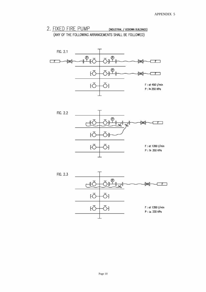
APPENDIX 5
Page 10

APPENDIX 5
Page 11

APPENDIX 5
Page 12

APPENDIX 6 Testing and Commissioning Checklist for Staircase Pressurization System
Reference
Address: ...................................................................................................... ......................................................................................................
FSD Ref.: FP 19/20/43/47/78*...................................
FSD Acceptance Letter/Approval Date: ........................................................................................................................
FSI Working Drawing Ref. : ...........................................................................................................................................
Approved Building Plan Ref.: ......................................................................... Dated: ................................................ Section I – General items for all staircase pressurization systems installed in the building 1.1 Measuring and testing instrument / equipment calibration
Measuring instrument used for testing purpose shall be provided in duplicate and calibrated in the past 3 months.
Type Model No. Serial No. Calibration Cert. No. Remarks a. b. c. d. e. f. g. h. i. j.
1.2 Documentation
Yes No Remarks a. Equipment list of staircase pressurization system c/w related
test report is attached.
[ ]
[ ]
b. Equipment list of builder’s work (such as doorset, door closer & etc.) c/w related test report is attached.
[ ]
[ ]
c. Certifying the building air tightness condition during the testing is equivalent to the occupation condition.
[ ]
[ ]
1.3 Staircase pressurization working drawings against building plans
Yes No N/A Remarks a. Classifications of pressurized spaces for means of escape /
firefighting & rescue tally with approved building plans.
[ ]
[ ]
[ ]
b. Designations of staircase number and fireman’s lift number, fire fighting access number tally with approved building plans.
[ ]
[ ]
[ ]
c. Locations of staircase pressurization plant rooms tally with approved building plans.
[ ]
[ ]
[ ]
d. Fire resistance rating of plant rooms is same as the pressurized space.
[ ]
[ ]
[ ]
e. Air intake positions tally with approved building plans.
[ ] [ ] [ ]
f. Discharge positions of over pressure relief tally with approved building plans.
[ ]
[ ]
[ ]
* Delete as appropriate
Page 1

APPENDIX 6 Section II – For each staircase pressurization system only
(Separate copy of Section II should be attached to respective pressurization system)
2.1 Description
a. Designation of pressurized staircase (The designation should be the same as building plan & FSI drawing & test report.)
.....................
b. Pressurized space :- (Please tick as appropriate) - Escape staircase; or
[ ]
- Fire fighting staircase
[ ]
c. Equipment to be provided :-
- Single fan with motor; or
[ ]
- Duplicate fans complete with motors; or
[ ]
- Single fan with duplicate motors [ ]
d.
Design air velocity passes through the door between pressurized space and accommodation area
............. m/s
e.
Design differential pressure between the pressurized space and accommodation
............. Pa
f.
Design door opening force
............. N (≤ 100N) 2.2 Test report
(All systems should be tested and endorsed by registered professional engineer before final test with Fire Services Inspecting Officer.) Appendix Remarks a. Pressure test report of all ductwork (including builder’s
work, ducts, shafts or other construction)
b.
Air velocity measurement report
c.
Door opening force measurement report
d.
Differential pressure measurement report
e.
System performance test report
2.3 Visual inspection
Yes No N/A Remarks a. Air intake
(Item a.1 to a.5 for air intake not located at roof floor )
a.1 Notice in English & Chinese characters “Staircase pressurization intake for (pressurized space)” ((增壓空間)的樓梯增壓入風口) is provided.
[ ]
[ ]
[ ]
a.2 Position of air intake is located away from any potential fire hazards (such as basement smoke vent).
[ ]
[ ]
[ ]
a.3 Air duct is provided from the intake to the fan when air intake is distant from the fan.
[ ]
[ ]
[ ]
a.4 A smoke detector of a type suitable for use in air duct / plenum is installed.
[ ]
[ ]
[ ]
a.5 Pressurization system can be shut down when the duct type smoke detector is activated.
[ ]
[ ]
[ ]
(Items a.6 to a.13 for air intake located at roof floor)
a.6 Two air intakes, which spaced apart and facing different directions, are provided.
[ ]
[ ]
[ ]
Page 2
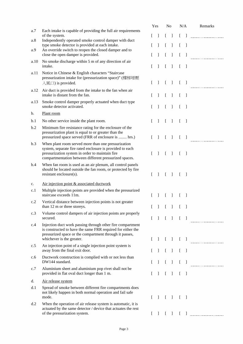
APPENDIX 6 Yes No N/A Remarks a.7 Each intake is capable of providing the full air requirements
of the system.
[ ]
[ ]
[ ]
a.8 Independently operated smoke control damper with duct type smoke detector is provided at each intake.
[ ]
[ ]
[ ]
a.9 An override switch to reopen the closed damper and to close the open damper is provided.
[ ]
[ ]
[ ]
a.10 No smoke discharge within 5 m of any direction of air intake.
[ ]
[ ]
[ ]
a.11 Notice in Chinese & English characters “Staircase pressurization intake for (pressurization space)” (樓梯增壓
入風口) is provided.
[ ]
[ ]
[ ]
a.12 Air duct is provided from the intake to the fan when air intake is distant from the fan.
[ ]
[ ]
[ ]
a.13 Smoke control damper properly actuated when duct type smoke detector activated.
[ ]
[ ]
[ ]
b.
Plant room
b.1 No other service inside the plant room.
[ ] [ ] [ ]
b.2 Minimum fire resistance rating for the enclosure of the pressurization plant is equal to or greater than the pressurized space served (FRR of enclosure is ........ hrs.)
[ ]
[ ]
[ ]
b.3 When plant room served more than one pressurization system, separate fire rated enclosure is provided to each pressurization system in order to maintain fire compartmentation between different pressurized spaces.
[ ]
[ ]
[ ]
b.4 When fan room is used as an air plenum, all control panels should be located outside the fan room, or protected by fire resistant enclosure(s).
[ ]
[ ]
[ ]
c.
Air injection point & associated ductwork
c.1 Multiple injection points are provided when the pressurized staircase exceeds 11m.
[ ]
[ ]
[ ]
c.2 Vertical distance between injection points is not greater than 12 m or three storeys.
[ ]
[ ]
[ ]
c.3 Volume control dampers of air injection points are properly secured.
[ ]
[ ]
[ ]
c.4 Injection duct work passing through other fire compartment is constructed to have the same FRR required for either the pressurized space or the compartment through it passes, whichever is the greater.
[ ]
[ ]
[ ]
c.5 An injection point of a single injection point system is away from the final exit door.
[ ]
[ ]
[ ]
c.6 Ductwork construction is complied with or not less than DW144 standard.
[ ]
[ ]
[ ]
c.7 Aluminium sheet and aluminium pop rivet shall not be provided in flat oval duct longer than 1 m.
[ ]
[ ]
[ ]
d.
Air release system
d.1 Spread of smoke between different fire compartments does not likely happen in both normal operation and fail safe mode.
[ ]
[ ]
[ ]
d.2 When the operation of air release system is automatic, it is actuated by the same detector / device that actuates the rest of the pressurization system.
[ ]
[ ]
[ ]
Page 3

APPENDIX 6
Yes No N/A Remarks d.3 When the accommodation space is partitioned or
compartmented into offices or similar unit, the air relief vent is provided at:-
i. Between the door into pressurized space and the start of the partitioning;
or
[ ]
[ ]
[ ]
ii. On each offices & units, the size of each air relief vent is capable of discharging the total air flow from pressurized space.
[ ]
[ ]
[ ]
d.4 Air release vent is located at or immediately below ceiling level
[ ]
[ ]
[ ]
Type of air release system
- Vertical shaft (go to d5 – d6);
[ ] or
- Special vents at the building periphery (go to d7 – d9);
[ ] or
- Mechanical air release (go to d10 – d12).
[ ]
d.5 Top vent is provided at the vertical shaft.
[ ] [ ] [ ]
d.6 When the shaft is designed for dual propose, automatic control fire & smoke damper is provided at each branch duct.
[ ]
[ ]
[ ]
d.7 Special vents for external vent are provided on at least two sides of the sealed building.
[ ]
[ ]
[ ]
d.8 Fail safe protection is provided to the ventilator.
[ ] [ ] [ ]
d.9 Components of ventilator are compliant with BS7346-1/ BS7346-2.
[ ]
[ ]
[ ]
d.10 Extraction flow rate is greater than the total pressurized air flow rate of all served staircase pressurization systems.
[ ]
[ ]
[ ]
d.11 Extraction system including ductwork is capable of working at the appropriate temperature and period of time (250oC for 1 hour for building with sprinkler system, 600oC for 2 hour for building without sprinkler system).
[ ]
[ ]
[ ]
d.12 The following items should be complied with, when the central exhaust system also serves for mechanical air release:-
i. Component & ductwork of central exhaust system is capable of working at the appropriate temperature and period of time (250oC for 1 hour for building with sprinkler system, 600oC for 2 hour for building without sprinkler system);
and
[ ]
[ ]
[ ]
ii. When the related pressurization system is actuated, function of VAC control system and VAC manual override switch for shutting down the central exhaust system is ignored;
and
[ ]
[ ]
[ ]
iii. For pressurization system for fire fighting, the local motorized smoke damper in fire floor is opened and dampers for other compartments / units is closed;
or For pressurization system for escape, the local
motorized smoke damper in fire floor and two above floor should be opened and dampers for other compartments / units are closed.
[ ]
[ ]
[ ]
Page 4

APPENDIX 6 Yes No N/A Remarks
e. Over pressure relief system
Type of over pressure relief system
- Automatic opening of the external exit doors on operation of the fan (go to e1 – e2);
[ ] or
- Barometric pressure relief vents / damper (go to e3 – e5);
[ ] or
- Mechanical exhaust (go to e6 – e7).
[ ]
e.1 Door lock, latch, bolt, push bar & etc. are not provided at the external exit doors
[ ]
]
[ ]
e.2 Warning label: “Over pressure relief door. Do not obstruct” (超壓時
放壓門,不要阻塞) is provided in English and Chinese characters at the external exit doors
[ ]
[ ]
[ ]
e.3 Wire mesh is provided at the external opening of relief vent / damper.
[ ] [ ] [ ]
e.4 Relief vent / duct passed through other fire compartment is enclosed by fire rated material; the FRR should be same of pressurized space or the compartment through it passes, whichever is greater.
[ ]
[ ]
[ ]
e.5 Free area of relief vent / damper “AX” ≧ 0.16 m2 x (total required airflow (m3/s) through the open doors – air supply satisfying the pressure differential requirement (m3/s) in pressurized space) *See equation (24) of section 14 of BS 5588: Part 4: 1988*
[ ]
[ ]
[ ]
e.6 Fan can be activated by differential pressure sensor
[ ] [ ] [ ]
e.7 Fan directly discharges to external or the discharge ductwork is constructed with fire rated material when passing through other fire compartment. The FRR of ductwork should be same as that of pressurized space or fire compartment passed, whichever is greater.
[ ]
[ ]
[ ]
f
Electrical & control
f.1 Electrical supplies for all equipment (such as fans, air relief damper, over pressure device, controller, supervisory panel & etc.) are fed from the same essential source.
[ ]
[ ]
[ ]
f.2 Requirement of main switchboard and/or local control panel :-
- Construction is complied with BS 5486 from not less than 2 mm panel steel and is installed in a room having …….. hour FRR (including self-closing doors) without other equipment installed therein; or
[ ]
[ ]
[ ]
- All controls, starters, relays, etc. shall be suitable for continuous operation at 250oC for not less than 1 hour.
[ ]
[ ]
[ ]
f.3 Requirement of power supply cable for pressurized system, controller, pressure sensor & etc.:-
- BS 6387 Cat. CWZ ; or
[ ]
- BS 6207 or BS EN 60702; or
[ ]
- Other international standards acceptable to the Director of Fire Services; or
[ ]
- Specification complying with criteria for exemption in Appendix 6 of FSD COP for Inspection, Testing and Maintenance of Installations and Equipment.
(Items )
[ ]
f.4 Separate pressure differential system is provided for each pressurized system.
[ ]
[ ]
[ ]
f.5 End of pressure sensing tube is properly terminated at the pressurized space and accommodation.
[ ]
[ ]
[ ]
f.6 End of sensing tube is mechanically protected.
[ ] [ ] [ ]
Page 5

APPENDIX 6 Yes No N/A Remarks f.7 Label of “Sensing point of staircase pressurization system” (樓梯增
壓系統感應點) is clearly indicated in English and Chinese characters.
[ ]
[ ]
[ ]
f.8 Protection is provided along the sensing tube.
[ ] [ ] [ ]
f.9 Power supplies for the differential pressure sensor, control, over pressure device, air release device are distributed from sub-circuit of staircase pressurization system.
[ ]
[ ]
[ ]
f.10 Manual override switch provided on local fan control panel is locked in “Automatic control” position.
[ ]
[ ]
[ ]
f.11 An indication signal is transmitted to supervisory control panel, when local fan control panel is in manual control mode.
[ ]
[ ]
[ ]
g. Construction work
g.1 Installations of door sets providing access to or from any pressurized space satisfy Building Authority’s requirements.
[ ]
[ ]
[ ]
g.2 All doors, closers, hardware, etc. are capable of use in an atmosphere of 35oC & 100% R.H.
[ ]
[ ]
[ ]
g.3 No supplementary gasket is provided to assist in preventing smoke leakage.
[ ]
[ ]
[ ]
g.4 Door sets are installed in such a manner to be smoke leakage proof.
[ ] [ ] [ ]
g.5 All joints between frames & building structure are provided with sealants in compliance with BS 476: Part 23.
[ ]
[ ]
[ ]
g.6 Self-closing door closers are provided for all doors.
[ ] [ ] [ ]
g.7 Finished sill under the closed doors is wear resistant.
[ ] [ ] [ ]
h.
Functional test
h.1 Performance test is carried out and the result is satisfactory.
[ ] [ ] [ ]
h.2 Measurement of door opening force is carried out and result is satisfactory.
[ ]
[ ]
[ ]
h.3 Measurement of differential pressure across the pressurized space and accommodation is carried out and the result is satisfactory.
[ ]
[ ]
[ ]
h.4 Measurement of pressurized air flow is carried out and the result is satisfactory.
[ ]
[ ]
[ ]
h.5 Air intake fire/smoke damper is closed when the duct type smoke detector is activated;
or
[ ]
[ ]
[ ]
Staircase pressurization system is shut down when the duct smoke detector at air intake is activated (for air intake only facing in one direction).
[ ]
[ ]
[ ]
h.6 In order to prevent over pressure in pressurized space, fail safe protection for over pressure release is provided on conditions of :-
- Failure of controller.
[ ] [ ] [ ]
- Failure of pressure switch.
[ ] [ ] [ ]
- Failure of wiring of pressure switch.
[ ] [ ] [ ]
- Failure of actuator of by-pass damper.
[ ] [ ] [ ]
- Failure of wiring of actuator (by-pass damper).
[ ] [ ] [ ]
- Failure of over pressure exhaust fan.
[ ] [ ] [ ]
Page 6

APPENDIX 6 Yes No N/A Remarks
h.7
Functional test of actuation
- by building fire alarm system is in order. (Note: Manual fire alarm is not recommended for air relief system which is automatically controlled in the fire zones)
[ ]
[ ]
[ ]
- by smoke detection system is in order.
[ ] [ ] [ ]
- by sprinkler system is in order.
[ ] [ ] [ ]
- by point type smoke detector mounted in the accommodation area adjacent to the doors (within 1 m) leading to the protected space at each storey served by the system is in order.
[ ]
[ ]
[ ]
- by supervisory control panel when selected in manual mode is in order.
[ ]
[ ]
[ ]
h.8 Functional test of response time The system is capable of achieving between 90% & 110% of the new volumetric requirements within 5 sec. of a door being opened or closed (for the over pressure release system by using variable supply fans or dampers).
[ ]
[ ]
[ ]
h.9 Changeover from the duty equipment to the standby equipment is automatically operated when failure occurred in duty equipment.
[ ]
[ ]
[ ]
Section III –For all staircase pressurization system installed in the building
3.1 The checklist is totally ………. pages (including attached copies of Section II for each additional staircase pressurization system).
3.2 Attached ………. number(s) of appendix.
Test conducted by: Test certified by:
………………………………….….. (Signature) ………………………………….….. (Signature)
……………………………………… ……………………………………… Name of Works *Specialist/ Agent (in block letters) Full Name of Registered Professional Engineer (in block letters) ……………………………………… ………………………………………. Company Chop Register Number of Engineer
Date ………………………………… ……………………………………… Company Chop
Date ………………………………… * Delete as appropriate
Page 7

APPENDIX 6
Endorsed by:
………………………………….….. (Signature)
……………………………………… Name of FSI Contractor’s Representative (in block letters)
……………………………………… Company Chop
……………………………………….(RC / ) Name of FSI Contractor (FSI Contractor Registration Number)
Page 8

APPENDIX 7
Testing and Commissioning Checklist for Street Fire Hydrant System
I. REFERENCE
Project ……………………………………….………. FSD Ref. ………………………………………………….
Address .……………………………………………... Location .………………………………………………….
……………………………………………………..… …………………………………………………………….
II. TYPE OF SYSTEM Yes No N/A Remarks
2.1 Supplied Directly from Town Main [ ] [ ] [ ] ….……………..
2.2 Supplied from Gravity Tank [ ] [ ] [ ] ….……………..
2.3 Supplied from Pumps and Tank [ ] [ ] [ ] ….……………..
2.4 Supplied from Sea Water Pumps [ ] [ ] [ ] ….……………..
III. LAYOUT CHECKING AGAINST APPROVED BUILDING PLANS
FSD Ref. of Approved Building Plans……………………………………………………………………………………..
Tally with drawings?
Yes No N/A Remarks
3.1 Quantity of street hydrants [ ] [ ] [ ] ….……………..
3.2 Location of street hydrants [ ] [ ] [ ] ….……………..
3.3 Location of pump room/enclosure [ ] [ ] [ ] ….……………..
3.4 Location of tank [ ] [ ] [ ] ….……………..
3.5 Tank capacity [ ] [ ] [ ] ….……………..
IV. ON SITE INSPECTION
4.1 GENERAL
4.1.1 Hydrant body is painted in red for fresh water system and
in yellow for sea water system (with white band when fed
directly from government trunk main). [ ] [ ] [ ] ….……………..
4.1.2 For hydrant not in service, cap for 100mm outlet is
painted in blue. [ ] [ ] [ ] ….……………..
4.1.3 Each hydrant is equipped with a control valve. [ ] [ ] [ ] ….……………..
4.1.4 Each hydrant is equipped with an isolating valve
(applicable to system fed directly/indirectly from
government main). [ ] [ ] [ ] ….……………..
4.1.5 Spindle of underground hydrant valve is within 250 mm
to 500 mm below valve pit cover. [ ] [ ] [ ] ….……………..
4.1.6 Size of underground control valve pit cover is not greater
than 300 mm x 300 mm with “FH” marking engraved on
the surface.
(Remarks: Isolating valve pit cover shall conform to
WSD standard.) [ ] [ ] [ ] ….……………..
Page 1

APPENDIX 7
Yes No N/A Remarks
4.1.7 The valve pit of control valve is located between 1.5 m
to 3 m from the street hydrant. [ ] [ ] [ ] ….……………..
4.1.8 The valve pit of control valve is located outside the
designated emergency vehicular access. [ ] [ ] [ ] ….……………..
4.1.9 V-shaped arrow head (100 mm high and 50 mm wide)
pointing toward the control valve is painted on hydrant
top (yellow arrow for red hydrant and red arrow for
yellow hydrant). [ ] [ ] [ ] ….……………..
4.1.10 The hydrant number with size not less than 75 mm is
painted at the hydrant (in yellow for red hydrant and in
red for yellow hydrant). [ ] [ ] [ ] ….……………..
4.1.11 There is no obstruction within 1.5 m in front and on two
sides of the hydrant. [ ] [ ] [ ] ….……………..
4.1.12 Tank refilling system is in efficient working order
(applicable to system with tank). [ ] [ ] [ ] ….……………..
4.1.13 The number assigned for the hydrant shall be painted on
the body facing the roadway with size not less than
75 mm (in yellow for red hydrant and in red for yellow
hydrant). [ ] [ ] [ ] ….……………..
4.2 PUMP (if provided)
4.2.1 Duplicate pumps are provided for duty and standby use. [ ] [ ] [ ] ….……………..
4.2.2 Mode of power for driving the pump is:
4.2.2.1 Electricity [ ] or ……………………………….
4.2.2.2 Secondary power supply provided. [ ] [ ] [ ] ….……………..
4.2.2.3 If no, diesel engine driven standby pump provided. [ ] [ ] [ ] ….……………..
4.2.2.4 Starting instruction for diesel engine driven pump
are prominently displayed in the pump room
enclosure. [ ] [ ] [ ] ….……………..
4.2.3 No automatic means of stopping the pump other than
by switching off at the pump room/enclosure. [ ] [ ] [ ] ….……………..
4.2.4 For duplicate electric motor driven pump arrangement,
the pump starters are wired through a selector switch
for duty and standby pump selection. [ ] [ ] [ ] ….……………..
4.2.5 The motor/engine for the pump is rated to give
20% more power in addition to the hydraulic power
required for the rated flow of the system. [ ] [ ] [ ] ….……………..
4.2.6 Pumps are permanently primed. [ ] [ ] [ ] ….……………..
Page 2

APPENDIX 7
Yes No N/A Remarks
4.2.7 Non-return valve(s) are provided to
prevent water backflow into the water
tank if provided. [ ] [ ] [ ] ….……………..
4.2.8 All pumps are housed in suitable room/enclosure
designed solely for accommodating pumps or
equipment for fire service installations. [ ] [ ] [ ] ….……………..
4.2.9 Pump room/enclosure are laid clear of any
exit or normal communication routes
through the premises. [ ] [ ] [ ] ….……………..
4.2.10 Pump room/enclosure is clearly marked in English
and Chinese characters. [ ] [ ] [ ] ….……………..
4.2.11 Pump room/enclosure is suitably locked to prevent
unauthorised tampering. [ ] [ ] [ ] ….……………..
4.3 SUPPLY TANK (if provided)
4.3.1 Water tank and its capacity are clearly marked in
English and Chinese characters. [ ] [ ] [ ] ….……………..
4.3.2 Fire Service Completion Advice issued. [ ] [ ] [ ] ….……………..
4.3.3 For system where the tank bottom is more than 20m
above the outlet coupling of the lowest street hydrant,
a bypass pipe (of the same size as the pump suction
pipe) is provided at the pump suction and discharge pipe.
(Please see Figure C in Annex I) [ ] [ ] [ ] ….……………..
V. SYSTEM TESTING
(applicable to system with pumps)
5.1 The pump starts automatically upon opening of
any hydrant outlet. [ ] [ ] [ ] ….……………..
5.2 Other than the jockey pump, the pump can only be
stopped manually at the pump room, once started. [ ] [ ] [ ] ….……………..
5.3 The standby pump is energized within 15 seconds
upon failure of the duty pump. [ ] [ ] [ ] ….……………..
5.4 For diesel engine driven pump, the operation of the
pump starting pressure switch is not affected by mains
power failure. [ ] [ ] [ ] ….……………..
5.5 The status of each pump comprising “Power Supply
On”, “Pump Running” and “Pump Failed” are
monitored and displayed at the pump room. [ ] [ ] [ ] ….……………..
5.6 The pump status signals are repeated to:
Fire control centre [ ] or
A status panel at the building main entrance [ ] or ….……………………………
Page 3

APPENDIX 7
Yes No N/A Remarks
5.7 Tank refilling system is in efficient working order
(applicable to system with tank). [ ] [ ] [ ] ….……………..
VI. FIELD MEASUREMENTS
6.1 Flow rate and pressure tested in accordance
with Figure ………. in Annex I.
6.2 When discharging at two 65mm outlets simultaneously:
Flow at one 65mm outlet (l/min) : ……………………………..
Running Pressure (kPa) : …..…………………………
VII. GENERAL COMMENTS & REMARKS
______________________________________________________________________________________________
______________________________________________________________________________________________
______________________________________________________________________________________________
______________________________________________________________________________________________
______________________________________________________________________________________________
Test conducted by:
………………………………….….. (Signature)
………………………………………
Name of FSI Contractor’s Representative (in block letters)
………………………………………
Company Chop
……………………………………….(RC / )
Name of FSI Contractor (FSI Contractor Registration Number)
Date …………………………………
Page 4

APPENDIX 7
Annex I
FIGURES FOR EQUIPMENT ARRANGEMENT FOR TESTING OF PEDESTAL STREET HYDRANT
(2 OPTIONS TO SUIT SITE CONDITIONS)
FIGURE A
FIGURE B
Page 5

APPENDIX 7
FIGURE C
(SCALE: N.T.S.)
NOTES:
(1) “H” IS THE HEIGHT DIFFERENCE BETWEEN THE TANK BOTTOM AND THE CENTRE LINE OF THE OUTLET COUPLING OF THE
LOWEST STREET HYDRANT IN THE SYSTEM.
(2) IF H > 20m , THEN A BYPASS PIPE IS REQUIRED AT THE PUMP SETS.
Page 6

Appendix 8
Fire Service Installations – Equipment List
(To be appended to Form FSI/501)
FP Ref. no. 43/19/20 ………………………. Address of Premises: ………………………………………………………………………………….
Item System/ Equipment Manufacturer /
Model No. / Part No. (a)
FSD Approval / Acceptance Reference
(If available) (b)
Listing Certificates / Records / Documents / Printouts from Product Certification Bodies
(c)
UL FM LPCB VdS Others
A Automatic Actuating Device A1 Emergency exit device A2 Electromagnetic door releasing device to be
used in conjunction with automatic fire alarm system B Automatic Fixed Installation other than Water
B1 Fixed carbon dioxide installation B2 Fixed clean agent installation B3 Fixed dry chemical installation
C Automatic Fire Alarm System C1 Fire alarm control panel C2 Heat detector C3 Smoke detector C4 Beam detector C5 Smoke detector with integration device C6 Flame detector C7 Intrinsically safe/ explosion proof detector
(Revised in December 2014)
Page 1 of 6
This is to confirm that either original copies of above mentioned documents or their photocopies which have been checked as true and correct, are appended to this Equipment List.
………………………………………… …………………… ( RC / ) ………………….… ………………..
Full Name of FSI Contractor Signature Registration Number Company Chop Date

Item System/ Equipment Manufacturer/
model no./ part no. (a)
FSD Approval/
Acceptance Reference
(If available) (b)
Listing Certificates/Records/Documents/Printouts from Product Certification Bodies
(c)
UL FM LPCB VdS Others
C8 Alarm / sounder integrated with strobe light to be used in conjunction with automatic fire alarm system D Manual Fire Alarm System
D1 Manual call point D2 Alarm bell
E Automatic Fixed Installation using water E1 Deluge system E1.1 a) Deluge valve E1.2 b) Sprinkler head E1.3 c) Alarm valve E2 Drencher System E3 Water Spray System E3.1 a) Water spray nozzle E3.2 b) Deluge valve E4 Sprinkler system E4.1 a) Sprinkler head E4.2 b) Alarm valve E4.3 c) Accelerator E4.4 d) Butterfly valve (motorized) E4.5 e) Flow switch
Page 2 of 6
This is to confirm that either original copies of above mentioned documents or their photocopies which have been checked as true and correct, are appended to this Equipment List.
………………………………………… …………………… ( RC / ) ………………….… ………………..
Full Name of FSI Contractor Signature Registration Number Company Chop Date

Item System/ Equipment Manufacturer/
model no./ part no. (a)
FSD Approval/
Acceptance Reference
(If available) (b)
Listing Certificates/Records/Documents/Printouts from Product Certification Bodies
(c)
UL FM LPCB VdS Others
E4.6 f) Piping and associated fittings e.g. CPVC piping/fittings
E4.7 g) Vortex inhibitor E4.8 h) Sprinkler water storage tank other than concrete E4.9 i) Sprinkler control and indicator panel E4.10 j) Pressure switch E5 Water mist system
F Fire Hydrant/ Hose Reel System F1 Hose reel unit (incl. hose reel tubing, nozzle and drum) F2 Hydrant inlet/ outlet valve F3 FS inlet/ fireboat inlet
G Fixed Automatically Operated Approved Appliance (Wall / Ceiling Mounted Type)
G1 Fixed sprayer unit H Fixed Foam System/ Equipment
H1 Foam Monitor H2 Foam proportioner / maker H3 Bladder tank H4 Ratio flow controller H5 Foam nozzle H6 Foam water nozzle
Page 3 of 6
This is to confirm that either original copies of above mentioned documents or their photocopies which have been checked as true and correct, are appended to this Equipment List.
………………………………………… …………………… ( RC / ) ………………….… ………………..
Full Name of FSI Contractor Signature Registration Number Company Chop Date

Item System/ Equipment Manufacturer/
model no./ part no. (a)
FSD Approval/
Acceptance Reference
(If available) (b)
Listing Certificates/Records/Documents/Printouts from Product Certification Bodies
(c)
UL FM LPCB VdS Others
I Gas Detection System I1 Ammonia gas I2 Carbon monoxide gas I3 Carbon dioxide gas I4 Chlorine gas I5 Hydrogen gas I6 Methane gas I7 Special gases used in micro-electronics industry
J Hand-Operated Approved Appliances J1 Fire Blanket J2 Portable Fire Extinguisher J2.1 a) Carbon dioxide J2.2 b) Clean agent J2.3 c) Dry powder J2.4 d) Foam J2.5 e) Water J2.6 f) Miscellaneous J3 g) Wheeled type fire extinguisher
Page 4 of 6
This is to confirm that either original copies of above mentioned documents or their photocopies which have been checked as true and correct, are appended to this Equipment List.
………………………………………… …………………… ( RC / ) ………………….… ………………..
Full Name of FSI Contractor Signature Registration Number Company Chop Date

Item System/ Equipment Manufacturer/
model no./ part no. (a)
FSD Approval/ Acceptance Reference
(If available) (b)
Listing Certificates/Records/Documents/Printouts from Product Certification Bodies
(c)
UL FM LPCB VdS Others
K Pressurization of Staircase K1 Probe type smoke detector K2 Ceiling smoke detector K3 Air release fan K4 Fire & smoke dampers and actuator K5 Fire-rated ductwork
L Smoke Extraction Systems L1 Probe type smoke detector L2 Ceiling smoke detector L3 Other type smoke detector L4 Smoke extraction fan L5 Fire & smoke dampers and actuator L6 Fire rated ductwork L7 Smoke curtains system L8 Smoke barriers L9 Smoke vents / discharge and actuators
M Ventilation/Air Conditioning Control System M1 Probe type smoke detector M2 Ceiling smoke detector
N Fire-resisting Cables N1 Audio / visual advisory system N2 Automatic actuating device N3 Automatic fixed installation other than water N4 Deluge system N5 Drencher system
Page 5 of 6
This is to confirm that either original copies of above mentioned documents or their photocopies which have been checked as true and correct, are appended to this Equipment List.
………………………………………… …………………… ( RC / ) ………………….… ………………..
Full Name of FSI Contractor Signature Registration Number Company Chop Date

Notes: 1. Column (a) must be filled in with details. 2. Sub-columns should be ticked as appropriate if certificates, records, or documents from the recognized laboratories/organizations are available and appended to the Equipment List. 3. Certificates, records, printouts, or documents from the recognized laboratories/organizations should adopt the item numbers such as ‘A1’, ‘B1’, etc., corresponding to the same of the
Equipment List. 4. Column (c) is for listed products, listing information can be checked via FSD Website: http://www.hkfsd.gov.hk/eng/source/licensing/product/fsi_check_listing.pdf
Item System/ Equipment Manufacturer/
model no./ part no. (a)
FSD Approval/ Acceptance Reference
(If available) (b)
Listing Certificates/Records/Documents/Printouts from Product Certification Bodies
(c)
UL FM LPCB VdS Others
N6 Fire hydrant / hose reel system N7 Fixed foam system N8 Pressurization of staircase N9 Ring main system with fixed pumps(s) N10 Smoke extraction system N11 Street fire hydrant system N12 Water mist system N13 Water spray system N14 Fire Service water supply system N15 Emergency generator N16 Emergency lighting N17 Exit sign N18 Fire alarm system N19 Fire detection system N20 Fireman’s lift N21 Sprinkler system
O Others
Page 6 of 6
This is to confirm that either original copies of above mentioned documents or their photocopies which have been checked as true and correct, are appended to this Equipment List.
………………………………………… …………………… ( RC / ) ………………….… ………………..
Full Name of FSI Contractor Signature Registration Number Company Chop Date