Embed Size (px)
Citation preview

セラミック管とガラス管
速断とタイムラグ
定格電流:100mA~20A
定格電圧:125V,250Vac
低遮断容量と高遮断容量
寸法:Ф5x20mm,Ф3.6x10mm
製品特徴 Features and Benefits
Ceramic and Glass Tube
Fast Acting and Time Lag
Rated Current:100mA~20A
Rated Voltage:125V,250Vac
Low and High Breaking Capacity
Physical Dimensions:Ф5x20mm,Ф3.6x10mm
ヒューズ Fuse

専門用語 Glossary of Terms
過電流時に回路遮断する保護装置です。
An overcurrent protective device with a fusible link that oper-ates and permanently opens the circuit on an overcurrent condition.
過負荷とショート時に迅速的に回路遮断できるヒューズです。こういうヒューズは過負荷ラッシュ電流に耐えられません。UL認証或いは認可された速断ヒューズは、一般的に200%~250%の定格電流時に、5秒以内に回路遮断できます。IEC基準では速断型ヒューズが二種類あります。
A fuse which opens on overload and short circuits very quickly. This type of fuse is not designed to withstand tempo-rary overload currents associated with some electrical load. UL listed or recognized fast acting fuses would typically open within 5seconds when subjected to 200% to 250% of its rat-ed current. IEC has two categories of fast acting fuses:
Fとは速断との意味です。10倍定格電流時に、1ms~10ms間に回路遮断できます。
F=Fast acting, opens on 10X rated current within 0.001 seconds to 0.01 seconds.
FFとは超速断との意味です。10倍定格ヒューズ時に1ms以内で回路遮断できます。
FF=Very fast acting, opens on 10X rated current within less than 0.001 seconds.
遮断時間遅延して、瞬間的な、損害のないラッシュ電流が流されても動作しないように作られており、設計の時に、継続的な過負荷電流と短絡電流に対して、UL基準で決めているように、一般的に200%~250%の定格電流時に、回路遮断する時間が2分間以内にする必要があります。
IEC基準ではタイムラグヒューズが二種類あります。
A fuse with a built-in delay that allows temporary and harm-less inrush currents to pass without operating, but is so de-signed to open on sustained overloads and short circuits. UL listed or recognized time delay fuses typically open in 2 minutes maximum when subjected to 200% to 250% of rated current. IEC has two categories of time delay fuses: Tとはタイムラグとの意味です。10倍定格電流時に、10ms~100m
s間に回路遮断できます。
T=Time Lag, opens on 10X rated current within 0.01 seconds to 0.1 seconds.
TTとは超タイムラグとの意味です。10倍定格電流時に、100ms~1s間に回路遮断できます。
TT=Long time Lag, opens on 10X rated current within
0.1 seconds to 1 second.
電流ヒューズの定格電流は決められたテスト条件で通電可能な電流値を表します。電流ヒューズには定格電流が表示されています。標示の仕方は数字、英文字、カラーリングのどっちでもいいです。 The rated current of a fuse identifies its current-carrying capacity based on a controllable set of test conditions. Each fuse is marked with its rated current. This rating can be identified with a numeric, alpha, or color code mark. Color codes can be found in each product’s data sheet.
使用できる最大安全電圧です。それを超えると、過負荷電流と短絡電流に対しての遮断能力が影響されます。
A maximum open circuit voltage in which a fuse can be used, yet safely interrupt an overcurrent. Exceeding the voltage rating of a fuse impairs its ability to clear an overload or short circuit safely.
DCとAC電流を別々に同じな抵抗器を通させて、同じ時間で発生した熱量が同じなら、該当DCを該当ACの有効値と言われて、実効電流と言われます。
The R.M.S. (root mean square) value of any periodic current is equal to the value of the direct current ,which flowing through a resistance, produces the same heating effect in the resistance as the periodic current does.
回路を閉める時に、回路に流れる電流です。25の条件では、定格電流の80%以下であるべきです。例えば、定格電流はが1Aのヒューズなら、800mA以下の回路で使用することを勧めます。環境温度が高い場合、さらに通常運転電流を下げる必要があります。
The normal operating current of a circuit is the level of cur-rent drawn (in RMS or dc amperes) after it has been ener-gized and is operating under normal conditions. An operating current of 80% or less of rated current is recommended for operation at 25 to avoid nuisance openings. For example, a fuse with a Rated Current of 1A is usually not recommend-ed in circuits with normal operating currents of more than 800mA. Further derating is required at elevated ambient tem-peratures.
規定時間に対するジュール積分値です。これは溶断に必要なジュール熱です。I2tは溶断I2t、アーク放電I2t、或いは両者の合計の意味です。
The melting, arcing, or clearing integral of a fuse, termed I2t, is the thermal energy required to melt, arc, or clear a specific current. It can be expressed as melting I2t, arcing I2t or the sum of them, clearing I2t.
定格負荷の2倍~5倍を超えて、通常の電流回路を流れる電流です。
Can be classified as an overcurrent which exceeds the nor-mal full load current of a circuit by 2 to 5 times its magnitude and stays within the normal current path.
回路に流れている通常負荷電流以上の電流です。過負荷電流と短絡電流を含めます。
A condition which exists in an electrical circuit when the nor-mal load current is exceeded. Overcurrents take on two sep-arate characteristics-overloads and short circuits.
電源入れる時に、明らかな突入電流がなく、電流が瞬間的に安定値まで、上昇し、より高い数値まで上昇しない時の負荷です。
An electrical load which is characterized by not drawing any significant inrush current. When a resistive load is energized, the current rises instantly to its steady state value, without first rising to a higher value.
ヒューズ Fuse
速断型ヒューズ Fast Acting Fuse
タイムラグヒューズ Time Lag Fuse
定格電流 Rated Current
定格電圧 Rated Voltage
実効電流 RMS Current
通常運転電流 Normal Operating Current
公称溶断I2t Ampere squared secondsI2t
過負荷 Overload
過電流 Overcurrent
抵抗負荷 Resistive load
ヒューズ Fuse

手順 Procedure 注意項目 Expound
スタート
Start
関係設計資料の準備。
Prepare related design information.
安全規格認証
Safety Approval
ご使用になる設備の安全規格認証によって、ヒューズの安全規格認証を決めること。ここでは、IEC安全規格認証或いはUL安全規格認証取得したものを選定すること。
The safety approvals required for fuse shall be upon to the end product. It is deter-
mined initially IEC standard or UL standard.
寸法
Dimensions
設計する時に回路空間の制限
The space limit of circuit in design.
取り付け方
Mounting mode.
定格電圧
Rated Voltage
定格電圧は使用される回路電圧以上でなければならい。 The Rated Voltage of the fuse shall be greater than, or equal to the available cir-cuit voltage.
電気回路で回路を通らずに短絡(ショート)した電流で、通常全負荷時の電流の数十倍、数百倍、数千倍を超えています。
An overcurrent that leaves the normal current path and greatly exceeds the normal full load current of the circuit by a factor of tens, hundreds, or thousands times.
アーク放電の発生瞬間から消滅するまでの時間です。 The amount of time from the instant the fuse link has melted until the overcurrent is interrupted, or cleared.
溶断時間とアーク放電時間の合計時間です。
The total time between the beginning of the overcurrent and the final opening of the circuit at rated voltage by an overcurrent protective device. Clearing time is the total of the melting time and the arcing time.
ヒューズが、通常の負荷条件で、回路中で正常に繋いでいる状態ですが、過電流時に回路を遮断し、内部のアーク放電に耐える機能があります。
During normal load conditions, the fuse must carry the normal operating current of the circuit without nuisance openings. How-ever, when an overcurrent occurs the fuse must interrupt the overcurrent and withstand the voltage across the fuse after inter-nal arcing.
下記の項目通りにヒューズを選定してください。
To properly select a fuse the following items must be considered:
定格電圧(AC 或いは DC ) Rated Voltage (AC or DC Voltage)
定格電流 Rated Current
定常動作電流 Normal operating current
環境温度 Ambient temperature
過負荷条件と溶断時間 Overload conditions and opening time
ショート電流 Available short circuit current
公称溶断I2t Ampere squared seconds(I2t)
パルスとサージ電流特性 Pulse and In-rush characteristics
保護される設備と部品の特性 Characteristics of equipment or components to be protected
取り付け空間と寸法 Physical size and available board space
安全規格等の要求 Standards requirements
ショート電流 Short Circuit
アーク放電時間 Arcing Time
遮断時間 Clearing Time
過電流保護の選定 Selecting Overcurrent Protection
選定手順 Selection Process
ヒューズ Fuse

遮断容量
Interrupting Rating AC
遮断容量の電流はご使用になる電器中の最大故障電流以上でなければならない。
The interrupting rating of the fuse should exceed the Maximum Fault Current of
the circuit.
概略タイプの選定
Initial Selection For Fuse Type
ご使用になる電器が電源を入れる時に起動電流があるか確認。起動電流を、回路中での正常電流とする場合、タイムラグ型或いは普通溶断型ヒューズを選定。
Does there exist “starting current” in a circuit when the end product turns on or
off? The “starting current” is normal for some circuit and requires the time-lag fuse
or medium time-lag fuse.
定格電流の上限IUの確定
Upper Limit For Rated Current IU
遮断に必要な電流と継続時間(該当条件は設計者が回路の保護要求によって決める)。関連タイプの時間電流曲線を参考し、要求に満足できる最大定格電流を上限IUとする。
The overload current and lasting time in which a fuse must function (It may be
specified on the specific protection needs of circuit by a design engineer.). Refer-
ring to the Time-Current curve, the maximum Rated Current which meet the re-
quirement would be taken as the upper limit for Rated Current IU.
定格電流の下限 ILの確定
Lower Limit For Rated Current IL
ヒューズに流れる定常状態電流(回路によって違う)。
Steady state current through a fuse (based on the specific circuit).
IEC規格及びUL規格のヒューズの定格電流の差別、「定常電流」ご参考。
The difference of Rated Current for fuse designed to IEC standard and UL
standard, refer to STEADY STATE CURRENT.
環境温度がヒューズの通電容量に対しての影響、「環境温度」ご参考。
Effect of ambient temperature on current-carrying capacity of fuse, refer to
AMBIENT TEMPERATURE.
パルス(ラッシュ電流、突入電流、始動電流、過渡電流等)がヒューズの寿
命に対しての影響、「パルス」ご参考。
Effect of pulse (including surge currents, starting current, in-rush currents and
transients) on life time of fuse, refer to PULSE.
始動電流及び持続時間は関連タイプの時間電流曲線と照合してください。
“Starting current” and duration should be compared to Time-Current curve of
relevant fuse.
上記五項目を考慮した上で、ご要求に満足できる最小定格電流を下限ILとする。
According to the above 5 factors, the minimum Rated Current which meets the
SET Fuseモデルと定格電流の選定
SET Fuse Model & Rated Current
上記項目を評価した上で、最適なモデルと定格電流を選定。
According to the above factors, choose the most appropriate model and rated
current.
IU≥IL場合、IL~IUの間の規格のヒューズを選定。
When IU≥IL , any rating is available from the range of IL to IU.
IU<IL場合、その他のタイプのヒューズを選定。
When IU<IL, recommend to select another type fuse.
検証
Proving
サンプルが実回路で動作させてみる必要がある。
The sample shall be trial-operation in the actual circuit.
終わり
End
ヒューズ Fuse
実応用時と試験室の時、条件が違う時があります、例えば、
There exist the different conditions between the actual appli-ance and test conditions, such as:
ヒューズホルダー使用要否Fuse-holder;
回路中ケーブルの横断面積
Connecting cable size;
ヒューズとクリップの接触抵抗等
Contacting resistance between fuse clip and fuse, etc.
上記項目を考慮し、25条件で下記条件に満足できるヒューズを選定してください。 The above factors should be taken into consideration when selecting a fuse at a 25 ambient temperature. To ensure the fuse operating continuously and properly, the following conditions shall be required:
IEC規格:ヒューズの定格電流In=定常電流/0.9。
Fuse designed to IEC standard: Rated Current (In)=steady state current of circuit/0.9.
UL規格:ヒューズの定格電流In=定常電流/0.75。
Fuse designed to UL standard: Rated Current (In)=steady state current of circuit/0.75.
ヒューズの通電容量が25条件で測定するが、環境温度に影響されます。環境温度が高ければ高いほど、ヒューズの寿命が短く、通電容量が低くなります。周囲の環境温度を考慮した上で、ヒューズを選定してください。環境温度がヒューズの通電容量に対しての影響が下記の通りです。
The current carrying capacity tests of a fuse are performed at 25 and will be effected by the changes of the ambient tem-perature. The higher the ambient temperature is, the shorter the fuse life time will be, and the lower the current carrying capacity will be. So the ambient temperature shall be consid-ered for proper fuse selection. Refer to the following charts showing its effect on the current carrying capacity of all kinds of fuse:
(1)環境温度が一般なタイムラグと普通溶断型ヒューズの
通電容量及び5In時の溶断時間に対しての影響を表しま
す。
Effect on rating and opening time in 5In of traditional time-lag and medium time-lag fuse.
(2)環境温度が速断型ヒューズの通電容量及び5In時の溶断時間に対しての影響を表します。
Effect on rating and opening time in 5In of fast acting fuse.
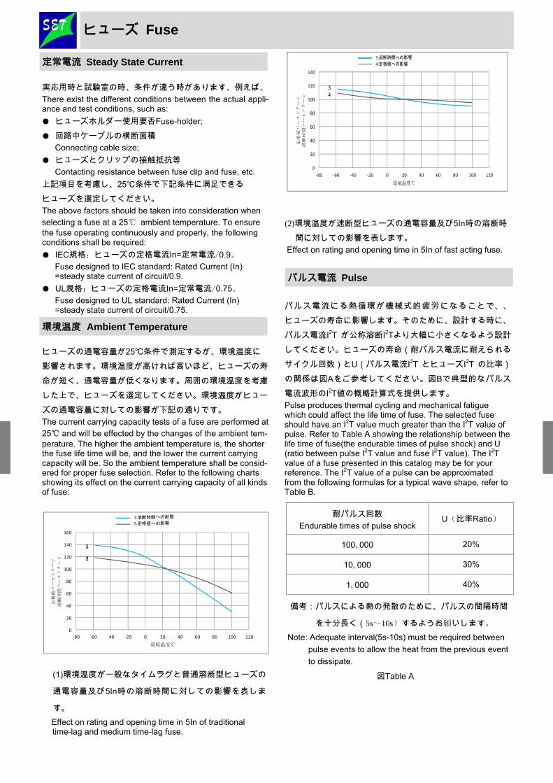
パルス電流にる熱循環が機械式的疲労になることで、、ヒューズの寿命に影響します。そのために、設計する時に、パルス電流I2T が公称溶断I2Tより大幅に小さくなるよう設計してください。ヒューズの寿命(耐パルス電流に耐えられるサイクル回数)とU(パルス電流I2T とヒューズI2T の比率)の関係は図Aをご参考してください。図Bで典型的なパルス電流波形のI2T値の概略計算式を提供します。
Pulse produces thermal cycling and mechanical fatigue which could affect the life time of fuse. The selected fuse should have an I2T value much greater than the I2T value of pulse. Refer to Table A showing the relationship between the life time of fuse(the endurable times of pulse shock) and U (ratio between pulse I2T value and fuse I2T value). The I2T value of a fuse presented in this catalog may be for your reference. The I2T value of a pulse can be approximated from the following formulas for a typical wave shape, refer to Table B.
備考:パルスによる熱の発散のために、パルスの間隔時間
を十分長く(5s~10s)するようお願いします。
Note: Adequate interval(5s-10s) must be required between
pulse events to allow the heat from the previous event
to dissipate.
図Table A
環境温度 Ambient Temperature
パルス電流 Pulse
耐パルス回数
Endurable times of pulse shock U(比率Ratio)
100,000 20%
10,000 30%
1,000 40%
定常電流 Steady State Current
ヒューズ Fuse
0
20
40
60
80
100
120
140
160
‐80 ‐60 ‐40 ‐20 0 20 40 60 80 100 120
定格
値パ
ーセ
ンテ
ージ
溶断
時間パ
ーセ
ンテ
ージ
環境温度
1:溶断時間への影響
2:定格値への影響
1
2
1
2
0
20
40
60
80
100
120
140
‐80 ‐60 ‐40 ‐20 0 20 40 60 80 100 120
定格値パー
センテージ
溶断時間パーセンテージ
環境温度
3:溶断時間への影響
4:定格値への影響
34

選定したヒューズの検証は実際保護される回路で検証すべきです。選定したヒューズが回路で正常的に動作できることを確保するために、この検証は定常条件と故障条件で実施しなければなりません。 The selected sample should be tested in the actual circuit to verify the right selection. The testing should include the tests un-der normal and fault conditions to ensure that the fuse will operate properly in the circuit.
検証 Proving
波形
Wave Shape
I2t計算公式 i12t1 (1/3)(i1
2+i1i2+i22)t1 (1/3)i1
2t1 (1/2)i12t1 (1/5)i1
2t1 (1/2)i12t1
図Table B
i2 i1
t1
方形波 Rectangle wave
i1
t1
台形波 Trapezoid wave
i1
t1
三角形波 Triangle wave
i1
t1
正弦波 Sine wave
t1 t1
変形波 Distortion wave
i1 or
t1
充、放電形波 Charge or Discharge wave
i1
ヒューズ Fuse

外形寸法Φ5mm X 20mm
Φ5mm X 20mm physical size
速断
Fast Acting
低遮断容量
Low-breaking capacity
ガラス管,ニッケルメッキブラスキャップ構造
Glass tube, Nickel-plated brass endcap construction
執行基準 IEC60127-2/シート2.GB9364-2/シート2
Designed to IEC60127-2/Sheet2.GB9364-2/Sheet2
プリンター Printers エアコン Air conditioners 省エネ照明バラスト Energy-saving Lighting ballasts パワーサプライ Power supplies パワーアダプター Power adapters 電池充電器 Battery chargers テレビ/モニター TVs/Displays
S G F 520 –1A–L
CCC:1A~6.3A:2011010207516066
CQC:8A~10A:CQC11012065997
リード線付き Axial Leads 1A~10A:CQC11012065997
VDE:1A~10A:40033351
KC:1A~2A:SU05023-11007; 3.15A~6.3A:SU05023
-11008; 8A~10A:SU05023-11009
PSE:1A~5A:PSE11020385; 6.3A~10A:PSE11020386
リード線付き Axial Leads 1A~5A:PSE11020387;
6.3A~10A:PSE11020388
UL/cURus:1A~10A:E345932
主な特徴 Key Features
応用範囲 Applications
品番説明 Part Number System
安全規格 Agency Approvals
時間‐電流特性曲線 Time Current Curve
構造図 Structure Diagrams
寸法 Dimensions (mm) A B C D(Φ) E
5.0 10±2 20±0.5 5 21±1
F
38±2
G
97±2
D1(Φ)
5.5±0.2
d(Φ)
≤6.3A:0.65±0.02
>6.3A:0.80±0.02 +0.15 -0
+0.05 -0
ヒューズ Fuse, SGF520 Series, Fast Acting, Glass Tube
リード線 Axial Lead
半田 Solder Tin
キャップ Cap
チューブ Tube
抵抗エレメント Element
時間
Tim
e (s
)
電流Current (A)
ご参考まで Reference
Φ5 X 20
速断、ガラス管
ガラス管 Glass Tube
会社コード Company Code
速断 Fast Acting
寸法 Dimensions
定格電流 Rated Current リード線付き

モデル
Model
定格電流Rated
Current
定格電圧Rated
Voltage (Vac)
遮断容量Interrupting
Rating (amps ) at
Rated Voltage(50Hz) (A)
DC抵抗値Typical DC Cold Re-sistance (mΩ)※
最大電圧降下
Maximum Voltage
Drop (mV)
公称溶断I2t
Typical Melting
I²t(A²Sec)
安全規格取得状況
Agency Approvals
環境対応状況Environmental
CCC CQC VDE KC PSE cURus RoHS REACH
SGF520-200mA 200mA 250 35 1700
SGF520-250mA 250mA 250 35 1400
SGF520-315mA 315mA 250 35 1300
SGF520-400mA 400mA 250 35 1200
SGF520-500mA 500mA 250 35 1000
SGF520-630mA 630mA 250 35 650
SGF520-800mA 800mA 250 35 240
SGF520-1A 1A 250 35 95.00 150 1.50
SGF520-1.25A 1.25A 250 35 80.00 150 2.59
SGF520-1.6A 1.6A 250 35 60.00 140 4.25
SGF520-2A 2A 250 35 50.00 140 6.24
SGF520-3.15A 3.15A 250 35 32.00 150 8.93
SGF520-5A 5A 250 50 19.00 120 36.00
SGF520-6.3A 6.3A 250 63 15.00 130 46.04
SGF520-8A 8A 250 80 12.00 125 69.12
SGF520-10A 10A 250 100 9.00 125 144.00
SGF520-16A 16A 250 160 120 715.35
SGF520-20A 20A 250 200 120 945.78
技術参数 Specifications
溶断特性 Pre-arcing Time/Current Characteristic
2.1IN 2.75IN 4IN 10IN
最大 Maximum 最小 Minimum 最大 Maximum 最小 Minimum 最大 Maximum 最大 Maximum
32mA~100mA 30min 10ms 500ms 3ms 100ms 20ms
Above100mA ~6.3A 30min 50ms 2s 10ms 300ms 20ms
Above 6.3A~10A 30min 50ms 2s 10ms 400ms 40ms
Above 10A~20A 30min 100ms 6s 20ms 600ms 60ms
定格電流
Rated current
包装情報 Packaging Information
包装状態 説明
リード線無し
Endcaps
1000pcs/箱
10000pcs per carton.
リード線付き
Axial Leads
4000pcs/箱
4000pcs per carton.
リード線付き Axial Leads リード線無し Endcaps
-認証申請中 On-going.
※-DC抵抗値が10%定格電流以内で測定。 DC Cold Resistance (Measured at <10% of rated current).
-最大電圧降下が環境温度20で、定格電流で測定。Maximum Voltage Drop (voltage drop was measured at 20°C ambient temperature at rated cur-
rent).
ヒューズ Fuse, SGF520 Series, Fast Acting, Glass Tube Φ5 X 20
速断、ガラス管

外形寸法Φ5mm X 20mm
Φ5mm X 20mm physical size
タイムラグ
Time Lag
低遮断容量
Low-breaking capacity
ガラス管,ニッケルメッキブラスキャップ構造
Glass tube, Nickel-plated brass endcap construction
執行基準 IEC60127-2/シート3.GB9364-2/シート3
Designed to IEC60127-2/Sheet3.GB9364-2/Sheet3
プリンターー Printers エアコン Air conditioners 省エネ照明バラスト Energy-saving Lighting ballasts パワーサプライ Power supplies パワーアダプター Power adapters 電池充電器 Battery chargers テレビ/モニター TVs/Displays
S G T 520–1A–L
CCC:1A~6.3A :2011010207516067
CQC:8A~10A:CQC11012065996
リード線付き Axial Leads 1A~10A:CQC11012065996
VDE:1A~10A :40033355
KC:1A~2A:SU05023-11006; 3.15A~6.3A:SU05023
-11004; 8A~10A:SU05023-11005
リード線付き Axial Leads 1A~2A:SU05023-11006;
3.15A~6.3A:SU05023-11004; 8A~10A:SU05023-11005
PSE:1A~5A :PSE11020389; 6.3A~10A:PSE11020390
リード線付き Axial Leads 1A~5A :PSE11020391; 6.3A
~10A:PSE11020392
UL/cURus:1A~10A :E345932
リード線 Axial Lead
半田 Solder Tin
キャップ Cap
チューブ Tube
抵抗エレメント Element
ご参考まで Reference
時間
Tim
e (s
)
電流Current (A)
ヒューズ Fuse, SGT520 Series, Time Lag, Glass Tube
寸法 Dimensions (mm) A B C D(Φ) E
5.0 10±2 20±0.5 5 21±1
F
38±2
G
97±2
D1(Φ)
5.5±0.2
d(Φ)
≤6.3A:0.65±0.02
>6.3A:0.80±0.02 +0.15 -0
+0.05 -0
主な特性 Key Features
応用分野 Applications
品番説明 Part Number System
安全規格 Agency Approvals
時間‐電流特性曲線 Time Current Curve
構造図 Structure Diagrams
Φ5 X 20 タイムラグ、ガラス管
ガラス管 Glass Tube
会社コード Company Code
タイムラグ Time Lag
寸法 Dimensions
定格電流 Rated Current
リード線付き Axial

定格電流
Rated current
2.1IN 2.75IN 4IN
最大 Maximum 最小 Minimum 最大 Maximum 最小 Minimum 最大 Maximum 最小 Minimum 最大 Maximum
32mA~100mA 2min 200ms 10s 40ms 3s 10ms 300ms
Above100mA ~10A 2min 600ms 10s 150ms 3s 20ms 300ms
Above 10A~20A 2min 600ms 10s 150ms 3s 20ms 300ms
10IN
モデル
Model
定格電流Rated
Current
定格電圧Rated
Voltage (Vac)
遮断容量Interrupting
Rating (amps ) at Rated Volt-age(50Hz)
(A)
DC抵抗値Typical
DC Cold Re-
sistance (mΩ)※
最大電圧降下
Maximum Voltage
Drop (mV)
公称溶断I2t
Typical Melting
I²t(A²Sec)
安全規格取得状況
Agency Approvals
環境対応状況Environmental
CCC CQC VDE KC PSE cURus RoHS REACH
SGT520-100mA 100mA 250 35 2500 O
SGT520-125mA 125mA 250 35 2000
SGT520-160mA 160mA 250 35 1900
SGT520-200mA 200mA 250 35 1500
SGT520-250mA 250mA 250 35 1300
SGT520-315mA 315mA 250 35 1100
SGT520-400mA 400mA 250 35 1000
SGT520-500mA 500mA 250 35 900 O O O O O
SGT520-630mA 630mA 250 35 300 O O O O O
SGT520-800mA 800mA 250 35 250 O O O O O
SGT520-1A 1A 250 35 85.00 120 5.70
SGT520-1.25A 1.25A 250 35 56.00 120 11.20
SGT520-1.6A 1.6A 250 35 46.00 120 20.99
SGT520-2A 2A 250 35 38.00 120 30.80
SGT520-3.15A 3.15A 250 35 21.00 100 103.19
SGT520-5A 5A 250 50 12.00 100 117.50
SGT520-6.3A 6.3A 250 63 10.00 100 230.20
SGT520-8A 8A 250 80 8.00 100 355.84
O O O O
O O O O O
O O O O O
O O O O O
O O O O O
O O O O O
O O O O O
SGT520-10A 10A 250 100 5.50 100 570.00
SGT520-15A 15A 250 150 100 1100.2 O O O O O
SGT520-20A 20A 250 200 100 2735.5 O O O O O
-認証申請中 On-going.
※-DC抵抗値が10%定格電流以内で測定。 DC Cold Resistance (Measured at <10% of rated current).
-電圧降下が環境温度20で、定格電流で測定。Maximum Voltage Drop (voltage drop was measured at 20°C ambient temperature at rated current).
ヒューズ Fuse, SGT520 Series, Time Lag, Glass Tube
技術参数 Specifications
溶断特性 Pre-arcing Time/Current Characteristic
包装情報 Packaging Information
包装状態 説明
リード線無し
Endcaps
10000pcs/箱
10000pcs per carton.
リード線付き
Axial Leads
4000pcs/箱
4000pcs per carton.
リード線付き Axial Leads リード線無し Endcaps
Φ5 X 20 タイムラグ、ガラス管

外形寸法Φ5mm X 20mm Φ5mm X 20mm physical size
速断 Fast Acting
高遮断容量 High-breaking capacity
セラミック管,ニッケルメッキブラスキャップ構造
Ceramic tube, Nickel-plated brass endcap construction
執行基準:IEC60127-2/シート1.GB9364-2/1
Designed to IEC60127-2/Sheet1.GB9364-2/Sheet1
プリンター Printers エアコン Air conditioners 省エネ照明バラスト Lighting ballasts パワーサプライ Power supplies 電源アダプター Power adapters 電池充電器 Battery chargers テレビ/モニター TVs/Displays
S C F 520–1A–L
CCC:TBA CQC:TBA VDE:TBA KC:TBA PSE:TBA cURus:TBA
On-going
主な特性 Key Features
応用分野 Applications
品番説明 Part Number System
セラミック管 Ceramic Tube 会社コード Company Code
速断 Fast Acting
寸法 Dimensions
定格電流 Rated Current リード線付き
構造図 Structure Diagrams
安全規格 Agency Approvals
時間電流曲線 Time Current Curve
リード線 Axial Lead
半田 Solder Tin
キャップ Cap
チューブ Tube
フィラー Filler
抵抗エレメント
寸法 Dimensions (mm)
A B C D(Φ) E
5.0 10±2 20±0.5 5 21±1
F
38±2
G
97±2
D1(Φ)
5.5±0.2
d(Φ)
≤6.3A:0.65±0.02
>6.3A~10A:0.80±0.02
>10A:1.20±0.02
+0.15 -0
+0.05 -0
ヒューズ Fuse, SCF520 Series, Fast Acting, Ceramic Tube Φ5 X 20 速断、セラミック管

定格電流
Rated current
2.1IN 2.75IN 4IN 10IN
最大 Maximum 最小 Minimum 最大 Maximum 最小 Minimum 最大 Maximum 最大 Maximum
200mA~4A 30min 10ms 2s 3ms 300ms 20ms
Above 4A ~6.3A 30min 10ms 3s 3ms 300ms 20ms
Above 6.3A~10A 30min 40ms 20s 10ms 1s 30ms
Above 10A~20A 30min 40ms 20s 10ms 1s 40ms
モデル
Model
定格電流Rated
Current
定格電圧Rated
Voltage (Vac)
遮断容量Interrupting
Rating (amps ) at Rated Volt-age(50Hz)
(A)
DC抵抗値Typical
DC Cold Re-
sistance (mΩ)※
最大電圧降下Maxi-mum
Voltage Drop
公称溶断I2t
Typical Melting
I²t(A²Sec)
安全規格取得状況
Agency Approvals
環境対応状況Environmental
Status
CCC CQC VDE KC PSE cURus RoHS REACH
SCF520-200mA 200mA 250 1500 3500 O O O O O
SCF520-250mA 250mA 250 1500 2800 O O O O O
SCF520-315mA 315mA 250 1500 2500 O O O O O
SCF520-400mA 400mA 250 1500 2000 O O O O O
SCF520-500mA 500mA 250 1500 1800 O O O O O
SCF520-630mA 630mA 250 1500 1500 O O O O O
SCF520-800mA 800mA 250 1500 1200 O O O O O
SCF520-1A 1A 250 1500 1000 O O O O O
SCF520-1.25A 1.25A 250 1500 800 O O O O O
SCF520-1.6A 1.6A 250 1500 600 O O O O O
SCF520-2A 2A 250 1500 500 O O O O O
SCF520-2.5A 2.5A 250 1500 400 O O O O O
SCF520-3.15A 3.15A 250 1500 350 O O O O O
SCF520-4A 4A 250 1500 300 O O O O O
SCF520-5A 5A 250 1500 250 O O O O O
SCF520-6.3A 6.3A 250 1500 200 O O O O O
SCF520-8A 8A 250 1500 200 O O O O O
SCF520-10A 10A 250 1500 200 O O O O O
SCF520-15A 15A 250 600 150 O O O O O
SCF520-20A 20A 250 500 150 O O O O O
-認証申請中。 On-going.
※-DC抵抗値が10%定格電流以内で測定。 DC Cold Resistance (Measured at <10% of rated current).
-電圧降下が環境温度20で、定格電流で測定。Maximum Voltage Drop (voltage drop was measured at 20°C ambient temperature at rated current).
ヒューズFuse, SCF520 Series, Fast Acting, Ceramic Tube
技術参数Specifications
溶断特性 Pre-arcing Time/Current Characteristic
包装情報 Packaging Information
包装状態 説明
リード線無し
Endcaps
10000pcs/箱。
10000pcs per carton.
リード線付き
Axial Leads
4000pcs/箱。
4000pcs per carton.
リード線付きAxial Leads リード線無しEndcaps
Φ5 X 20 速断、セラミック管

外形寸法Φ5mm X 20mm Φ5mm X 20mm physical size
タイムラグ
Time Lag 高遮断容量
High-breaking capacity
セラミック管,ニッケルメッキブラスキャップ構造
Ceramic tube, Nickel-plated brass endcap construction
執行基準:IEC60127-2/シート5.GB9364-2/シート5
Designed to IEC60127-2/Sheet5.GB9364-2/Sheet5
プリンター Printers エアコン Air conditioners 省エネ照明バラスト Energy-saving Lighting ballasts パワーサプライ Power supplies 電源アダベター Power adapters 電池充電器 Battery chargers テレビ/モニター TVs/Displays
S C T 520–1A–L
CCC:TBA CQC:TBA VDE:TBA KC:TBA PSE:TBA UL/cURus:TBA
ご参考まで Reference
時間
Tim
e (s
)
電流Current (A)
寸法 Dimensions (mm)
A B C D(Φ) E
5.0 10±2 20±0.5 5 21±1
F
38±2
G
97±2
D1(Φ)
5.5±0.2
d(Φ)
≤6.3A:0.65±0.02
>6.3A~10A:0.80±0.02
>10A:1.20±0.02
+0.15 -0
+0.05 -0
リード線Axial Lead
半田 Solder Tin
キャップ Cap
チューブ Tube
フィラー Filler
エレメント Element
ヒューズFuse, SCT520 Series, Time Lag, Ceramic Tube
主な特性 Key Features
応用分野 Applications
品番説明 Part Number System
構造図 Structure Diagrams
安全規格 Agency Approvals
時間電流特性曲線 Time Current Curve
Φ5 X 20 タイムラグ、セラミック管
セラミック管 Ceramic Tube 会社コード Company Code
タイムラグ Time Lag
寸法 Dimensions
定格電流 Rated Current リード線付き

定格電流
Rated Current
2.1IN 2.75IN 4IN
最大 Maximum 最小 Minimum 最大 Maximum 最小 Minimum 最大 Maximum 最小 Minimum 最大 Maximum
200mA~800mA 30min 250ms 80s 50ms 5s 5ms 150ms
Above 800mA ~3.15A 30min 750ms 80s 95ms 5s 10ms 150ms
Above 3.15A~10A 30min 750ms 80s 150ms 5s 10ms 150ms
Above 10A~20A 30min 750ms 80s 150ms 5s 10ms 150ms
10IN
モデル
Model
定格電流Rated
Current
定格電圧Rated
Voltage (Vac)
遮断容量Interrupting
Rating (amps ) at Rated Volt-age(50Hz)
(A)
DC抵抗値Typical
DC Cold Re-
sistance (mΩ)※
最大電圧降下
Maximum Voltage
Drop (mV)
公称溶断I2t
Typical Melting
I²t(A²Sec)
安全規格取得状況
Agency Approvals
環境対応状況Environmental
CCC CQC VDE KC PSE cURus RoHS REACH
SCT520-200mA 200mA 250 1500 2100 O O O O O
SCT520-250mA 250mA 250 1500 1500 O O O O O
SCT520-315mA 315mA 250 1500 1100 O O O O O
SCT520-400mA 400mA 250 1500 1000 O O O O O
SCT520-500mA 500mA 250 1500 850 O O O O O
SCT520-630mA 630mA 250 1500 650 O O O O O
SCT520-800mA 800mA 250 1500 500 O O O O O
SCT520-1A 1A 250 1500 350 O O O O O
SCT520-1.25A 1.25A 250 1500 300 O O O O O
SCT520-1.6A 1.6A 250 1500 200 O O O O O
SCT520-2A 2A 250 1500 190 O O O O O
SCT520-2.5A 2.5A 250 1500 180 O O O O O
SCT520-3.15A 3.15A 250 1500 140 O O O O O
SCT520-4A 4A 250 1500 100 O O O O O
SCT520-5A 5A 250 1500 100 O O O O O
SCT520-6.3A 6.3A 250 1500 100 O O O O O
SCT520-8A 8A 250 1500 100 O O O O O
SCT520-10A 10A 250 1500 100 O O O O O
SCT520-15A 15A 250 600 90 O O O O O
SCT520-20A 20A 250 500 90 O O O O O
-認証申請中。 On-going.
※-DC抵抗値が10%定格電流以内で測定。 DC Cold Resistance (Measured at <10% of rated current).
-電圧降下が環境温度20で、定格電流で測定。Maximum Voltage Drop (voltage drop was measured at 20°C ambient temperature at rated current).
ヒューズFuse, SCT520 Series, Time Lag, Ceramic Tube
技術参数Specifications
溶断特性 Pre-arcing Time/Current Characteristic
包装情報 Packaging Information
包装状態 説明
リード線無し
Endcaps
10000pcs/箱。
10000pcs per carton.
リード線付き
Axial Leads
4000pcs/箱。
4000pcs per carton.
リード線付きAxial Leads リード線無しEndcaps
Φ5 X 20 タイムラグ、セラミック管

外形寸法Φ3.6mm X 10mm Φ3.6mm X 10mm physical size
速断 Fast Acting
低遮断容量 Low-breaking capacity
ガラス管、ニッケルメッキブラスキャップ構造
Glass tube, Nickel-plated brass endcap construction
執行基準:IEC60127-3/シート3.GB9364-3/シート3
Designed to IEC60127-3/Sheet3.GB9364-3/Sheet3
プリンター Printers エアコン Air conditioners 省エネ照明バラスト Energy-saving Lighting ballasts パワーサプライ Power supplies 電源アダプター Power adapters 電池充電器 Battery chargers テレビ/モニター TVs/Displays
S G F 3610–1A–L
CCC:TBA CQC:TBA VDE:TBA KC:TBA PSE:TBA UL/cURus:TBA
On-going
リード線 Axial Lead
半田 Solder Tin
キャップ Cap
チューブ Tube
エレメント Element
寸法 Dimensions (mm)
A B(Φ) C D(Φ) E G F(Φ)
10±1 3.6±0.1 11±1 4±0.15 30±1 71±2 ≤6.3A:0.60±0.02
>6.3:0.80±0.02
ヒューズFuse, SGF3610 Series, Fast Acting, Glass Tube
主な特性 Key Features
応用分野 Applications
安全規格 Agency Approvals
時間電流特性曲線 Time Current Curve
品番説明 Part Number System
構造図 Structure Diagrams
Φ3.6 X 10 速断、ガラス管
ガラス管 GalssTube
会社コード Company Code
遮断 Fast Acting
寸法 Dimensions
定格電流 Rated Current
リード線付き Axial

定格電流
Rated Current
2.1IN 2.75IN 4IN 10IN
最大 Maximum 最小 Minimum 最大 Maximum 最小 Minimum 最大 Maximum 最大 Maximum
200mA~6.3A 30min 10ms 3s 3ms 300ms 20ms
モデル
Model
定格電流Rated
Current
定格电压
Rated Voltage (Vac)
遮断容量Interrupting
Rating (amps ) at Rated Volt-age(50Hz)
(A)
DC抵抗値Typical
DC Cold Re-
sistance (mΩ)※
最大電圧降下
Maximum Voltage
Drop (mV)
公称溶断I2t
Typical Melting I²t(A²Sec)
安全規格取得状況
Agency Approvals
環境対応状況Environmental
Status
CCC CQC VDE KC PSE cURus RoHS REACH
SGF3610-200mA 200mA 250 35 480 O O O O O
SGF3610-250mA 250mA 250 35 440 O O O O O
SGF3610-315mA 315mA 250 35 400 O O O O O
SGF3610-400mA 400mA 250 35 370 O O O O O
SGF3610-500mA 500mA 250 35 350 O O O O O
SGF3610-630mA 630mA 250 35 320 O O O O O
SGF3610-800mA 800mA 250 35 300 O O O O O
SGF3610-1A 1A 250 35 280 O O O O O
SGF3610-1.25A 1.25A 250 35 280 O O O O O
SGF3610-1.6A 1.6A 250 35 250 O O O O O
SGF3610-2A 2A 250 35 240 O O O O O
SGF3610-2.5A 2.5A 250 35 200 O O O O O
SGF3610-3.15A 3.15A 250 35 180 O O O O O
SGF3610-4A 4A 250 40 160 O O O O O
SGF3610-5A 5A 250 50 150 O O O O O
SGF3610-6.3A 6.3A 250 63 150 O O O O O
-認証申請中。 On-going.
※-DC抵抗値が10%定格電流以内で測定。 DC Cold Resistance (Measured at <10% of rated current).
-電圧降下が環境温度20で、定格電流で測定。Maximum Voltage Drop (voltage drop was measured at 20°C ambient temperature at rated current).
ヒューズFuse, SGF3610 Series, Fast Acting, Glass Tube
技術参数Specifications
溶断特性 Pre-arcing Time/Current Characteristic
包装情報 Packaging Information
Φ3.6 X 10 速断、ガラス管
包装状態 説明
リード線無し
Endcaps TBA
リード線付き
Axial Leads TBA

外形寸法Φ3.6mm X 10mm Φ3.6mm X 10mm physical size
タイムラグ
Time Lag 低遮断容量
Low-breaking capacity
ガラス管、ニッケルメッキブラスキャップ構造
Glass tube, Nickel-plated brass endcap construction
執行基準:IEC60127-3/シート4.GB9364-3/シート4
Designed to IEC60127-3/Sheet4.GB9364-3/Sheet4
プリンター Printers エアコン Air conditioners 省エネ照明バラスト Energy-saving Lighting ballasts パワーサプライ Power supplies 電源アダプター Power adapters 電池充電器 Battery chargers テレビ/モニター TVs/Displays
S G T 3610–1A–L
CCC:TBA CQC:TBA VDE:TBA KC:TBA PSE:TBA UL/cURus:TBA
On-going
主な特性 Key Features
応用分野 Applications
安全規格 Agency Approvals
時間電流特性曲線 Time Current Curve
品番説明 Part Number System
ヒューズFuse, SGT3610 Series, Time Lag, Glass Tube
寸法 Dimensions (mm)
A B(Φ) C D(Φ) E G F(Φ)
10±1 3.6±0.1 11±1 4±0.15 30±1 71±2 ≤6.3A:0.60±0.02
>6.3:0.80±0.02
リード線 Axial Lead
半田 Solder Tin
キャップ Cap
チューブ Tube
エレメント Element
構造図 Structure Diagrams
Φ3.6 X 10 タイムラグ、ガラス管
ガラス管 Glass Tube
会社コード Company Code
タイムラグ Time Lag
寸法 Dimensions
定格電流 Rated Current
リード線付き Axial

定格電流
Rated Current
2.1IN 2.75IN 4IN
最大 Maximum 最小 Minimum 最大 Maximum 最小 Minimum 最大 Maximum 最小 Minimum 最大 Maximum
200mA~6.3A 2min 400ms 10s 150ms 3s 20ms 150ms
10IN
モデル
Model
定格電流Rated
Current
定格電圧Rated
Voltage (Vac)
遮断容量Interrupting
Rating (amps ) at Rated Volt-age(50Hz)
(A)
DC抵抗値Typical
DC Cold Re-
sistance (mΩ)※
最大電圧降下Maxi-mum
Voltage Drop
(mV)
公称溶断I2t
Typical Melting I²t(A²Sec)
安全規格取得状況
Agency Approvals
環境対応状況Environmental
Status
CCC CQC VDE KC PSE cURus RoHS REACH
SGT3610-200mA 200mA 250 35 260 O O O O O
SGT3610-250mA 250mA 250 35 240 O O O O O
SGT3610-315mA 315mA 250 35 220 O O O O O
SGT3610-400mA 400mA 250 35 200 O O O O O
SGT3610-500mA 500mA 250 35 190 O O O O O
SGT3610-630mA 630mA 250 35 180 O O O O O
SGT3610-800mA 800mA 250 35 160 O O O O O
SGT3610-1A 1A 250 35 140 O O O O O
SGT3610-1.25A 1.25A 250 35 130 O O O O O
SGT3610-1.6A 1.6A 250 35 120 O O O O O
SGT3610-2A 2A 250 35 100 O O O O O
SGT3610-2.5A 2.5A 250 35 100 O O O O O
SGT3610-3.15A 3.15A 250 35 100 O O O O O
SGT3610-4A 4A 250 40 100 O O O O O
SGT3610-5A 5A 250 50 100 O O O O O
SGT3610-6.3A 6.3A 250 63 100 O O O O O
-認証申請中。 On-going.
※-DC抵抗値が10%定格電流以内で測定。 DC Cold Resistance (Measured at <10% of rated current).
-電圧降下が環境温度20で、定格電流で測定。Maximum Voltage Drop (voltage drop was measured at 20°C ambient temperature at rated current).
ヒューズFuse, SGT3610 Series, Time Lag, Glass Tube
技術参数Specifications
溶断特性 Pre-arcing Time/Current Characteristic
包装情報 Packaging Information
Φ3.6 X 10 タイムラグ、ガラス管
包装状態 説明
リード線無し
Endcaps TBA
リード線付き
Axial Leads TBA

外形寸法Φ3.6mm X 10mm Φ3.6mm X 10mm physical size
速断 Fast Acting
低遮断容量 Low-breaking capacity
セラミック管、ニッケルメッキブラスキャップ構造
Ceramic tube, Nickel-plated brass endcap construction
執行基準 IEC60127-3/シート3.GB9364-3/シート3
Designed to IEC60127-3/Sheet3.GB9364-3/Sheet3
プリンター Printers エアコン Air conditioners 省エネ照明バラスト Energy-saving Lighting ballasts パワーサプライ Power supplies 電源アダベター Power adapters 電池充電器 Battery chargers テレビ/モニター TVs/Displays
S C F 3610–1A–L
CCC:TBA CQC:TBA VDE:TBA KC:TBA PSE:TBA UL/cURus:TBA
On-going
寸法 Dimensions (mm)
A B(Φ) C D(Φ) E G F(Φ)
10±1 3.6±0.1 11±1 4±0.15 30±1 71±2 ≤6.3A:0.60±0.02
>6.3:0.80±0.02
ヒューズFuse, SCF3610 Series, Fast Acting, Ceramic Tube
リード線 Axial Lead
半田 Solder Tin
キャップ Cap
チューブ Tube
エレメント Element
主な特性 Key Features
応用分野 Applications
安全規格 Agency Approvals
時間‐電流特性曲線 Time Current Curve
品番説明 Part Number System
構造図 Structure Diagrams
Φ3.6 X 10 速断、セラミック管
セラミック管 Ceramic Tube
会社コード Company Code
速断 Fast Acting
寸法 Dimensions
定格電流 Rated Current
リード線付き Axial

技術参数Specifications
モデル
Model
定格電流Rated
Current
定格電圧Rated
Voltage (Vac)
遮断容量Interrupting
Rating (amps ) at Rated Volt-age(50Hz)
(A)
DC抵抗値
Typical DC Cold
Re-sistance (mΩ)※
最大電圧降下Maxi-mum
Voltage Drop
(mV)
公称溶断I2t
Typical Melting I²t(A²Sec)
安全規格取得状況
Agency Approvals
環境対応状況Environmental
Status
CCC CQC VDE KC PSE cURus RoHS REACH
SCF3610-200mA 200mA 250 35 480 O O O O O
SCF3610-250mA 250mA 250 35 440 O O O O O
SCF3610-315mA 315mA 250 35 400 O O O O O
SCF3610-400mA 400mA 250 35 370 O O O O O
SCF3610-500mA 500mA 250 35 350 O O O O O
SCF3610-630mA 630mA 250 35 320 O O O O O
SCF3610-800mA 800mA 250 35 300 O O O O O
SCF3610-1A 1A 250 35 280 O O O O O
SCF3610-1.25A 1.25A 250 35 280 O O O O O
SCF3610-1.6A 1.6A 250 35 250 O O O O O
SCF3610-2A 2A 250 35 240 O O O O O
SCF3610-2.5A 2.5A 250 35 200 O O O O O
SCF3610-3.15A 3.15A 250 35 180 O O O O O
SCF3610-4A 4A 250 40 160 O O O O O
SCF3610-5A 5A 250 50 150 O O O O O
SCF3610-6.3A 6.3A 250 63 150 O O O O O
溶断特性 Pre-arcing Time/Current Characteristic
定格電流
2.1IN 2.75IN 4IN 10IN
最大 Maximum 最小 Minimum 最大 Maximum 最小 Minimum 最大 Maximum 最大 Maximum
200mA~6.3A 30min 10ms 3s 3ms 300ms 20ms
-認証申請中。 On-going.
※-DC抵抗値が10%定格電流以内で測定。 DC Cold Resistance (Measured at <10% of rated current).
-電圧降下が環境温度20で、定格電流で測定。Maximum Voltage Drop (voltage drop was measured at 20°C ambient temperature at rated current).
包装情報 Packaging Information
ヒューズFuse, SCF3610 Series, Fast Acting, Ceramic Tube Φ3.6 X 10 速断、セラミック管
包装状態 説明
リード線無し
Endcaps TBA
リード線付き
Axial Leads TBA

外形寸法Φ3.6mm X 10mm Φ3.6mm X 10mm physical size
タイムラグ
Time Lag 低遮断容量
Low-breaking capacity
セラミック管,ニッケルメッキブラスキャップ構造
Ceramic tube, Nickel-plated brass endcap construction
執行基準 IEC60127-3/シート4.GB9364-3/シート4
Designed to IEC60127-3/Sheet4.GB9364-3/Sheet4
プリンター Printers エアコン Air conditioners 省エネ照明バラスト Energy-saving Lighting ballasts パワーサプライ Power supplies 電源アダプター Power adapters 電池充電器 Battery chargers テレビ/モニター TVs/Displays
S C T 3610–1A–L
CCC:TBA CQC:TBA VDE:TBA KC:TBA PSE:TBA UL/cURus:TBA
On-going
ヒューズFuse, SCT3610 Series, Time Lag, Ceramic Tube
寸法 Dimensions (mm)
A B(Φ) C D(Φ) E G F(Φ)
10±1 3.6±0.1 11±1 4±0.15 30±1 71±2 ≤6.3A:0.60±0.02
>6.3:0.80±0.02
リード線 Axial Lead
半田 Solder Tin
キャップ Cap
チューブ Tube
エレメント Element
主な特性 Key Features
応用分野 Applications
安全規格 Agency Approvals
時間‐電流特性曲線 Time Current Curve
品番説明 Part Number System
構造図 Structure Diagrams
Φ3.6 X 10 タイムラグ、セラミック管
セラミック管 Ceramic Tube
会社コード Company Code
タイムラグ Time Lag
寸法 Dimensions
定格電流 Rated Current
リード線付き Axial

モデル
Model
定格電流Rated
Current
定格電圧Rated
Voltage (Vac)
遮断容量Interrupting
Rating (amps ) at Rated Volt-age(50Hz)
(A)
DC抵抗値Typical
DC Cold Re-
sistance (mΩ)※
最大電圧降下
Maximum Voltage
Drop (mV)
公称溶断I2t
Typical Melting I²t(A²Sec)
安全規格取得状況
Agency Approvals
環境対応状況Environmental
Status
CCC CQC VDE KC PSE cURus RoHS REACH
SCT3610-200mA 200mA 250 35 260 O O O O O
SCT3610-250mA 250mA 250 35 240 O O O O O
SCT3610-315mA 315mA 250 35 220 O O O O O
SCT3610-400mA 400mA 250 35 200 O O O O O
SCT3610-500mA 500mA 250 35 190 O O O O O
SCT3610-630mA 630mA 250 35 180 O O O O O
SCT3610-800mA 800mA 250 35 160 O O O O O
SCT3610-1A 1A 250 35 140 O O O O O
SCT3610-1.25A 1.25A 250 35 130 O O O O O
SCT3610-1.6A 1.6A 250 35 120 O O O O O
SCT3610-2A 2A 250 35 100 O O O O O
SCT3610-2.5A 2.5A 250 35 100 O O O O O
SCT3610-3.15A 3.15A 250 35 100 O O O O O
SCT3610-4A 4A 250 40 100 O O O O O
SCT3610-5A 5A 250 50 100 O O O O O
SCT3610-6.3A 6.3A 250 63 100 O O O O O
定格電流
Rated Current
2.1IN 2.75IN 4IN
最大 Maximum 最小 Minimum 最大 Maximum 最小 Minimum 最大 Maximum 最小 Minimum 最大 Maximum
200mA~6.3A 2min 400ms 10s 150ms 3s 20ms 150ms
10IN
技術参数Specifications
-認証申請中。 On-going.
※-DC抵抗値が10%定格電流以内で測定。 DC Cold Resistance (Measured at <10% of rated current).
-電圧降下が環境温度20で、定格電流で測定。Maximum Voltage Drop (voltage drop was measured at 20°C ambient temperature at rated current).
溶断特性 Pre-arcing Time/Current Characteristic
包装情報 Packaging Information
包装状態 説明
リード線無し
Endcaps TBA
リード線付き
Axial Leads TBA
ヒューズFuse, SCT3610 Series, Time Lag, Ceramic Tube Φ3.6 X 10 タイムラグ、セラミック管