Embed Size (px)
Citation preview
Functional Nanocomposites Laboratory
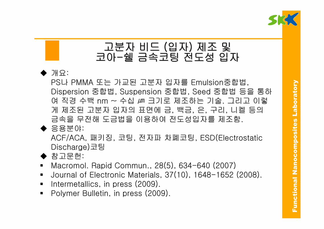
고분자고분자 비드비드 ((입자입자) ) 제조제조 및및코아코아--쉘쉘 금속코팅금속코팅 전도성전도성 입자입자
�� 개요개요: : PSPS나나 PMMA PMMA 또는또는 가교된가교된 고분자고분자 입자를입자를 EmulsionEmulsion중합법중합법, , Dispersion Dispersion 중합법중합법, Suspension , Suspension 중합법중합법, Seed , Seed 중합법중합법 등을등을 통하통하여여 직경직경 수백수백 nm ~ nm ~ 수십수십 ㎛㎛ 크기로크기로 제조하는제조하는 기술기술. . 그리고그리고 이렇이렇게게 제조된제조된 고분자고분자 입자의입자의 표면에표면에 금금, , 백금백금, , 은은, , 구리구리, , 니켈니켈 등의등의금속을금속을 무전해무전해 도금법을도금법을 이용하여이용하여 전도성입자를전도성입자를 제조함제조함..
�� 응용분야응용분야: : ACF/ACA, ACF/ACA, 패키징패키징, , 코팅코팅, , 전자파전자파 차폐코팅차폐코팅, ESD(Electrostatic , ESD(Electrostatic Discharge)Discharge)코팅코팅
�� 참고문헌참고문헌: : �� Macromol. Rapid Commun., 28(5), 634Macromol. Rapid Commun., 28(5), 634--640 (2007)640 (2007)�� Journal of Electronic Materials, 37(10), 1648Journal of Electronic Materials, 37(10), 1648--1652 (2008).1652 (2008).�� Intermetallics, in press (2009).Intermetallics, in press (2009).�� Polymer Bulletin, in press (2009).Polymer Bulletin, in press (2009).
Functional Nanocomposites Laboratory
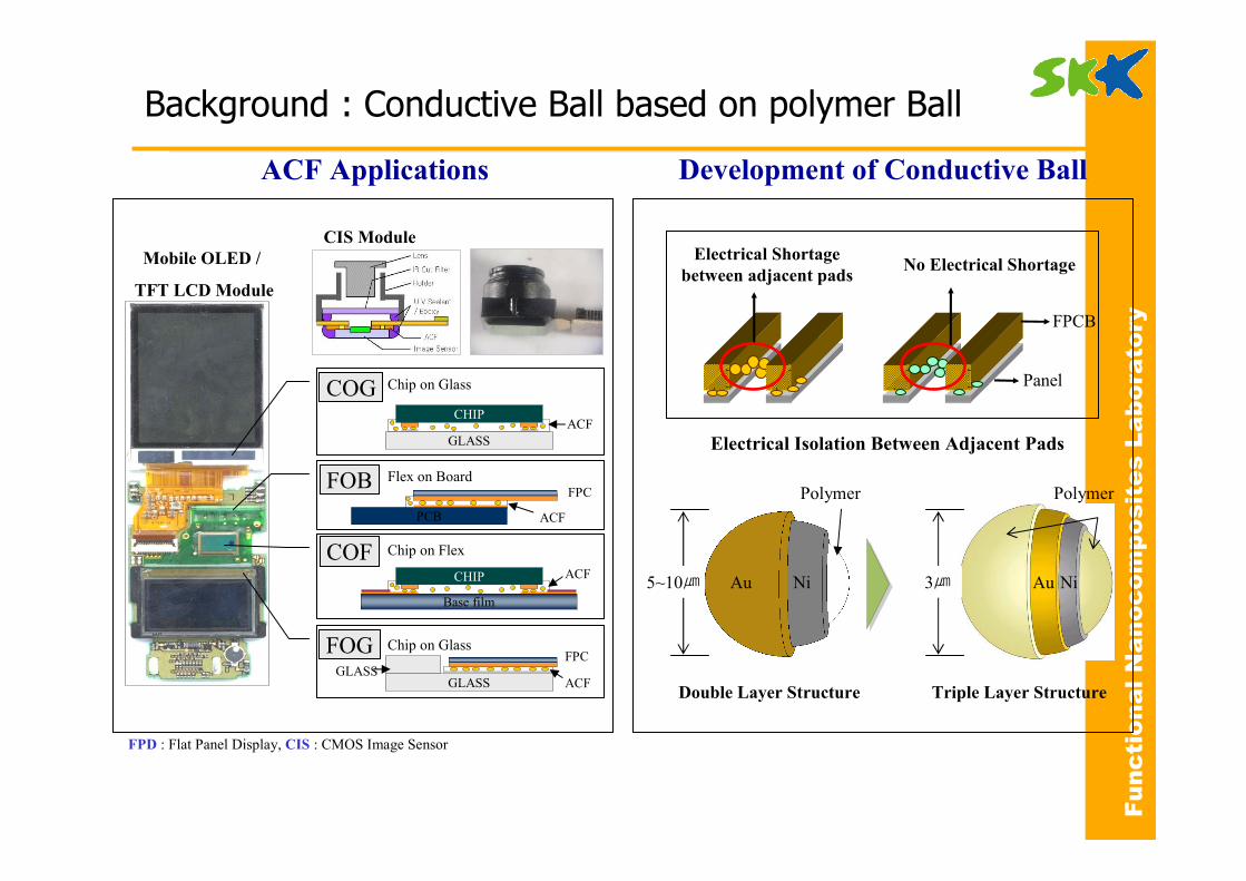
Background : Conductive Ball based on polymer Ball
FPD : Flat Panel Display, CIS : CMOS Image Sensor
ACF Applications Development of Conductive Ball
5~10㎛ Au Ni
Polymer
Au Ni
Polymer
3㎛
Double Layer Structure Triple Layer Structure
Electrical Isolation Between Adjacent Pads
Panel
FPCB
Electrical Shortage
between adjacent padsNo Electrical Shortage
FOB Flex on Board
ACF
FPC
PCB
COG Chip on Glass
GLASS
ACFCHIP
Chip on FlexCOF
Base film
ACFCHIP
GLASSGLASS
FPC
ACF
FOG Chip on Glass
Mobile OLED /
TFT LCD Module
CIS Module
Functional Nanocomposites Laboratory
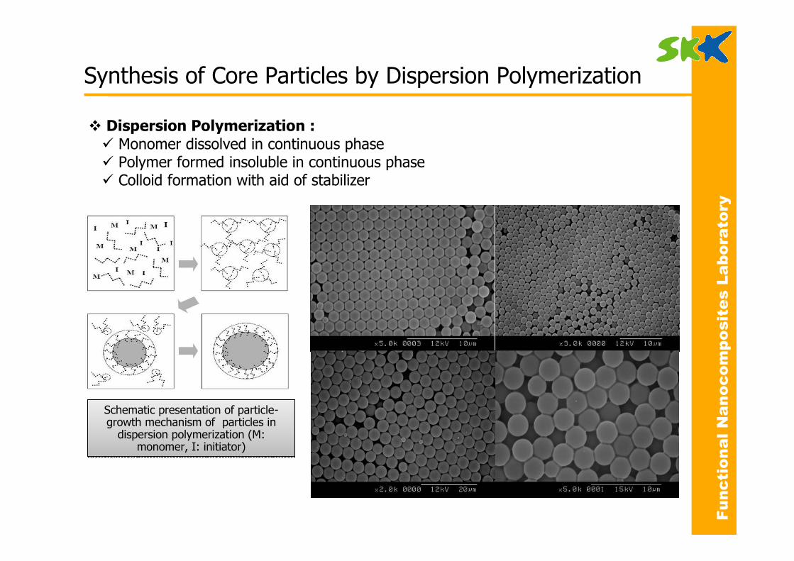
� Dispersion Polymerization :
� Monomer dissolved in continuous phase� Polymer formed insoluble in continuous phase� Colloid formation with aid of stabilizer
Schematic presentation of particle-growth mechanism of particles in
dispersion polymerization (M: monomer, I: initiator)
Schematic presentation of particle-growth mechanism of particles in
dispersion polymerization (M: monomer, I: initiator)
Synthesis of Core Particles by Dispersion Polymerization
Functional Nanocomposites Laboratory
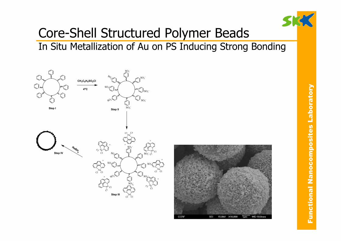
Core-Shell Structured Polymer BeadsIn Situ Metallization of Au on PS Inducing Strong Bonding
CH3C8H4SO2Cl
4oC
SO3-
SO3-
SO3-
SO 3-
SO3-
SO3-
SO3-
SO3-
SO3-
SO3-
SO3-
SO 3-
SO3-
SO3-
SO3-
SO3-
N N
AuCl Cl
+
N N
AuCl Cl
+
N
NAuCl
Cl
+
N
N
Au
ClCl
+
N N
AuCl Cl
+
N
NAuClCl
+
NN
AuCl
Cl
+
N
N
Au
ClCl
+
NaBH4
Step IV
Step I Step II
Step III
Functional Nanocomposites Laboratory
0 5 10 15-0.05
0.00
0.05
0.10
0.15
0.20
0.25
0.30
0.35
0.401.8 nm
Count Size Distribution
Particle diameter (nm)
A B C
0 20 40 60 80 100 120
0
100
200
300
400
[4 2 0][3 3 1][2 0 2]
[3 1 1][2 2 2]
[1 1 1]
Intensity
2-Theta
[2 0 0]
D
A B C
0 20 40 60 80 100 120
0
100
200
300
400
[4 2 0][3 3 1][2 0 2]
[3 1 1][2 2 2]
[1 1 1]
Intensity
2-Theta
[2 0 0]
A B C
0 20 40 60 80 100 120
0
100
200
300
400
[4 2 0][3 3 1][2 0 2]
[3 1 1][2 2 2]
[1 1 1]
Intensity
2-Theta
[2 0 0]
D
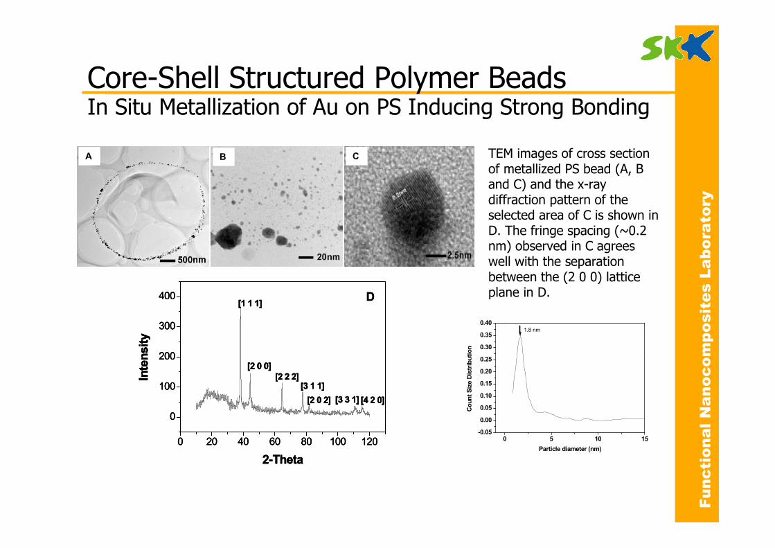
TEM images of cross section of metallized PS bead (A, B and C) and the x-ray diffraction pattern of the selected area of C is shown in D. The fringe spacing (~0.2 nm) observed in C agrees well with the separation between the (2 0 0) lattice plane in D.
Core-Shell Structured Polymer BeadsIn Situ Metallization of Au on PS Inducing Strong Bonding
Functional Nanocomposites Laboratory
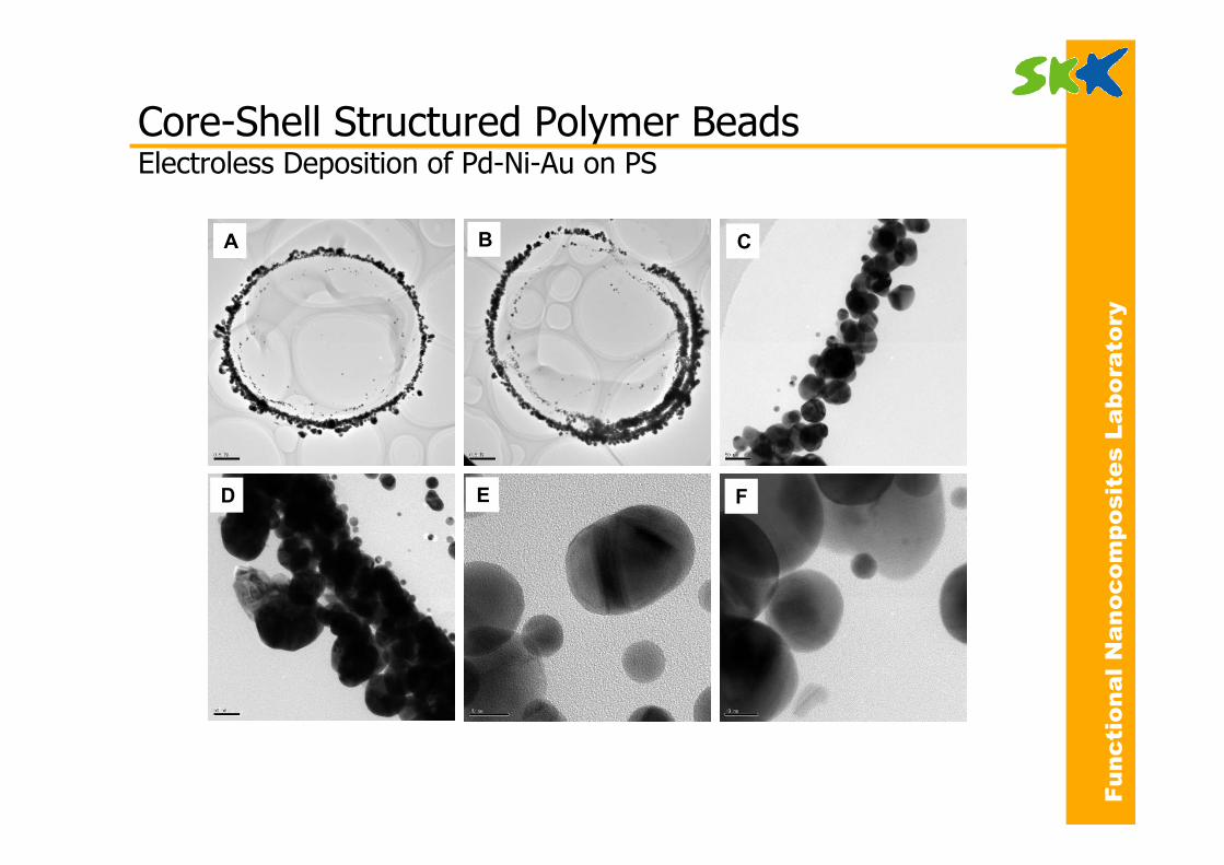
A B C
D E F
Core-Shell Structured Polymer BeadsElectroless Deposition of Pd-Ni-Au on PS
Functional Nanocomposites Laboratory
A
2 µm
B
2 µm
C
2 µm
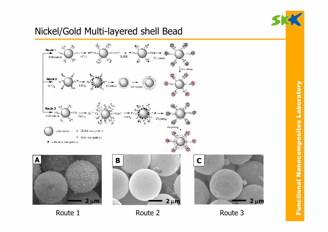
Route 1 Route 2 Route 3
Nickel/Gold Multi-layered shell Bead