Embed Size (px)
Citation preview

微腔光子学微腔光子学MicrocavityMicrocavity photonicsphotonics----Organic/Inorganic hybrid materials Organic/Inorganic hybrid materials based optical based optical microcavitiesmicrocavities and and applicationsapplications
Lei Xu
Department of Optical Science and EngineeringFudan University, Shanghai 200433, China

OutlinesOutlines
•• BackgroundBackground•• Important works in the fieldImportant works in the field•• Our worksOur works•• ConclusionConclusion
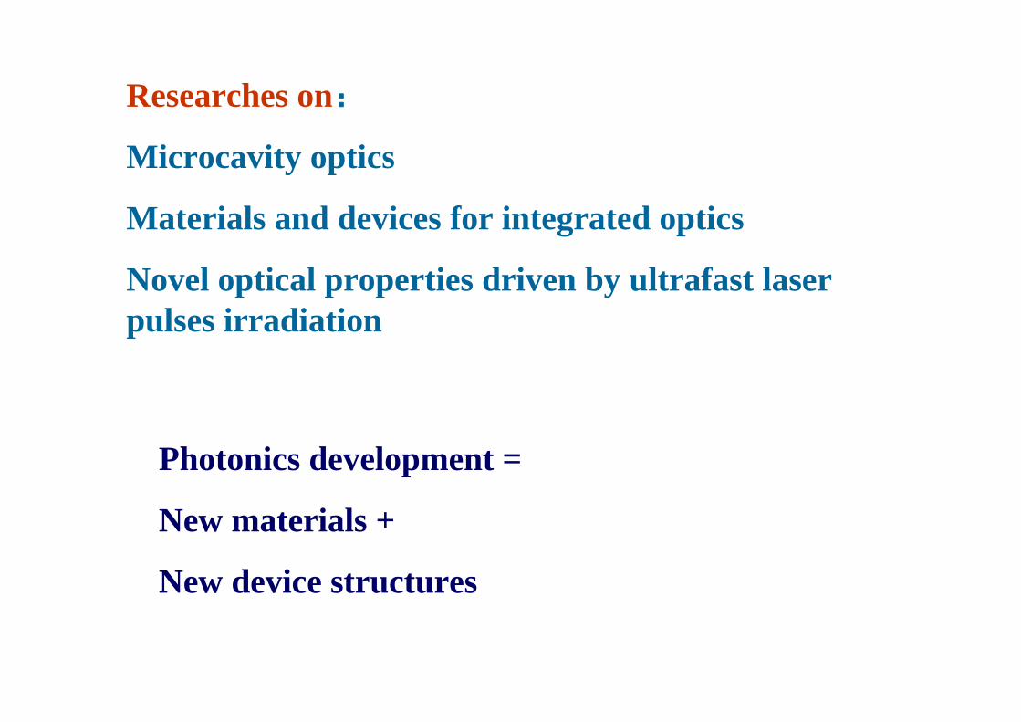
Researches on:
Microcavity optics
Materials and devices for integrated optics
Novel optical properties driven by ultrafast laser pulses irradiation
Photonics development =
New materials +
New device structures

Electronics
Micro-electronics
Integrated Circuit
VLSI circuit
Nano-electronics
Photonics
Micro-photonics
Integrated optics
Large scale integration
Nano-photonics


Vertical integration
光子芯片光子芯片 Photonic chipPhotonic chip

Optoelectronic system on chip
Optical interconnects

Optical Optical microcavitymicrocavity are important are important element in photonic integrated circuitelement in photonic integrated circuit
www.research.ibm.com/photonics/
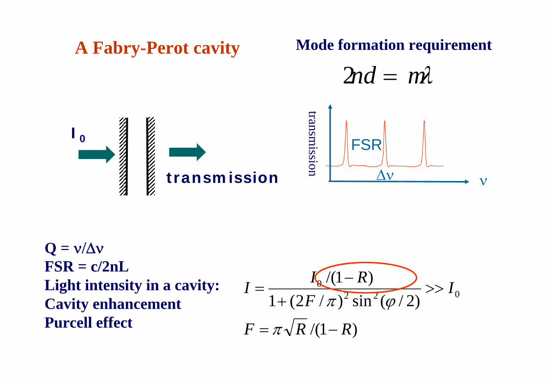
A Fabry-Perot cavity
ν
FSR
Δν
Q = ν/ΔνFSR = c/2nLLight intensity in a cavity:Cavity enhancementPurcell effect )1/(
)2/(sin)/2(1)1/(
0220
RRF
IF
RII
−=
>>+
−=
π
ϕπ
transmission
transmission
I0
λmnd =2Mode formation requirement
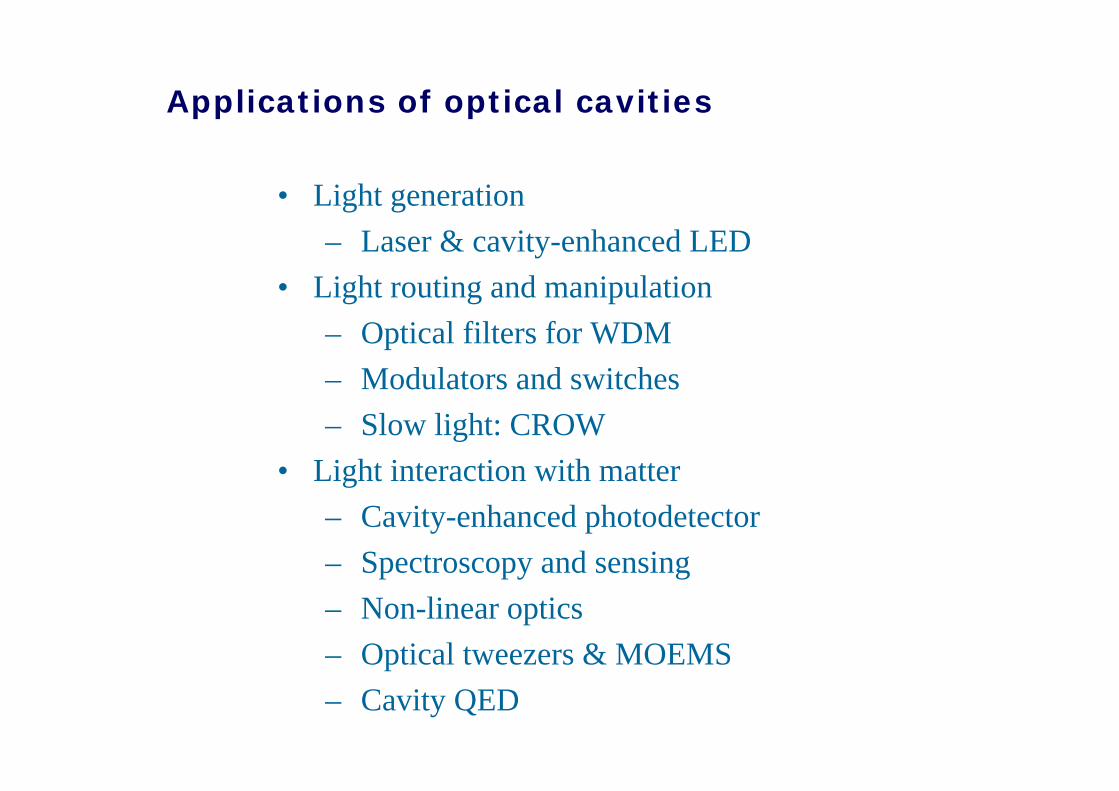
• Light generation– Laser & cavity-enhanced LED
• Light routing and manipulation– Optical filters for WDM– Modulators and switches– Slow light: CROW
• Light interaction with matter– Cavity-enhanced photodetector– Spectroscopy and sensing– Non-linear optics– Optical tweezers & MOEMS– Cavity QED
Applications of optical cavities

Conventional cavity
Micro-cavity
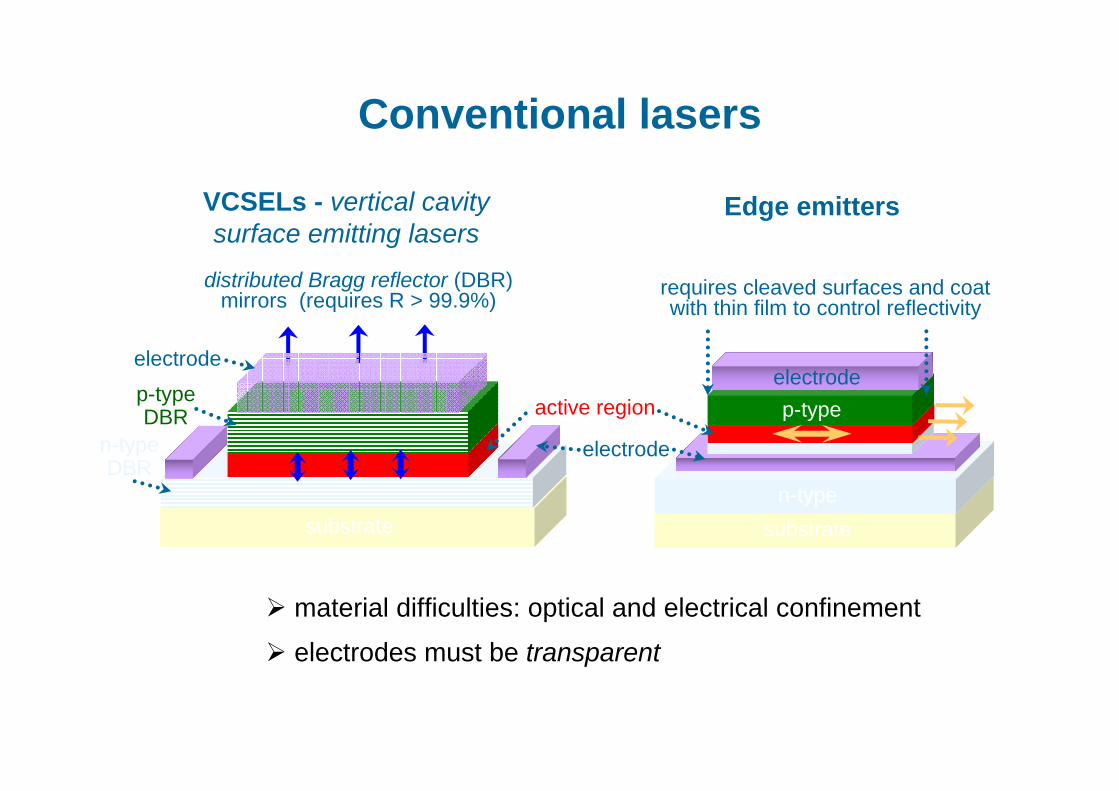
VCSELs - vertical cavity surface emitting lasers
material difficulties: optical and electrical confinement
electrodes must be transparent
distributed Bragg reflector (DBR) mirrors (requires R > 99.9%)
active region
electrode
substrate
n-type DBR
p-type DBR
electrode
Edge emitters
Conventional lasers
requires cleaved surfaces and coat with thin film to control reflectivity
substraten-type
p-typeelectrode

Whispering gallery modes: Total internal reflection (TIR)
top-face
θinc
n(ω)
substraten-type
p-typeelectrode
electrodeactive region
electrodes must be transparent
mirrors
100% reflectivity from sidewalls
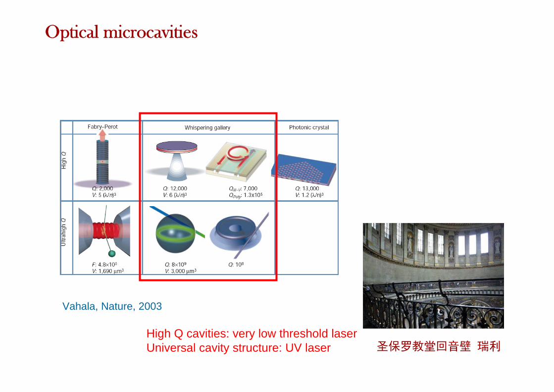
Vahala, Nature, 2003
High Q cavities: very low threshold laserUniversal cavity structure: UV laser 圣保罗教堂回音壁 瑞利
Optical microcavities

History of micro-cavity1939 Dielectric Resonators
(Propose WGM to create high-Q optical resonators)R. D. Richtmyer
1961 Stimulated emission into optical whispering modes of spheres(First experimental observation of WGM millimeter-sized
dielectric spheres of CaF2:Sm++ )C. G. B. Garret, W. Kaiser and W. L. Bond
1980 Observation of resonances in the radiation pressure on dielectric spheres
(Liquid droplets of micrometer-sized cavities)A. Ashkin and J. M. Dziedzic
1986 Lasing dropletsS. X. Qian, RK Chang
1992 Whispering-gallery mode micro-disk lasers (Two-dimensional semiconductor circular micro-disks)
S. L. McCall, A. F.J.Levi, R. E. Slusher

Topics (2010 ICTON)•Microcavity lasers and LEDs•Microresonator-based bio(chemical) sensors•Single-molecule sensors•Coupling and transport phenomena•Slow-light structures•Cavity opto-mechanics•Tunable cavities•Tuning optical properties of single emitters with microcavities•Optical bistability in microcavity structures•Quantum information processing with microresonators•Localized and quasi-localized photonic states in aperiodicstructures•Cavity polaritons and plasmons

Materials for optical microcavities
Semiconductors (Si, III-V, nano-materials)
RE-doped glasses
SiO2
Crystals (LiNbO3)
Polymers

Important Works
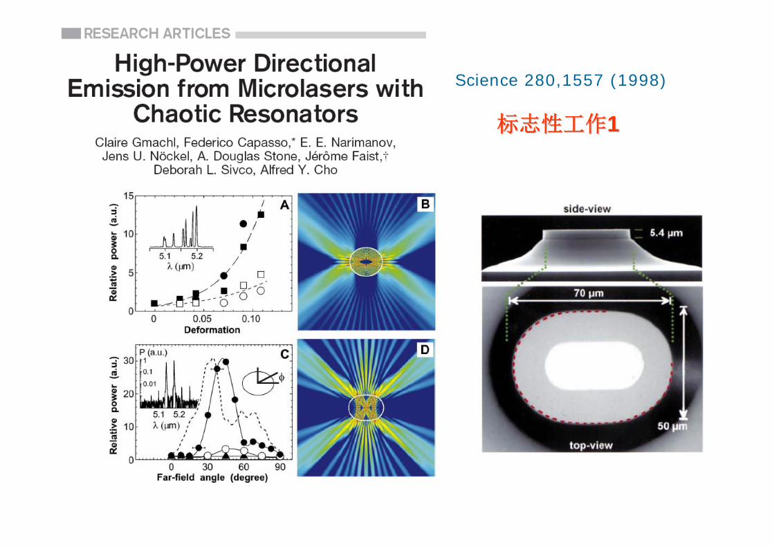
Science 280,1557 (1998)
标志性工作标志性工作11

标志性工作标志性工作IIII
Er doped silica sphere
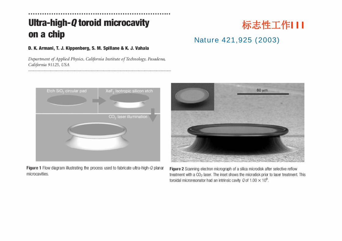
Nature 421,925 (2003)
标志性工作标志性工作IIIIII

Cavity mode photon lifetimeτ=43ns, Q = 3 × 10⁸

Ultralow level optical nonlinearity generation

Label-free optical bio-sensor detects environmental RI change
ANALYTICA CHIMICA ACTA 620, 8, 2008
Bio-sensing using optical microcavities
Tran
smis
sion
Wavelength
RI change

Using two microcavities with different chemical surface modification to detect DNA
Sensitivity: 6 pg/mm2
Biophysical Journal 85, 1974 (2003)

Optics Letters 31, 1319 (2006)Optics Express 15, 15523 (2007)
Opto-fluidic sensor
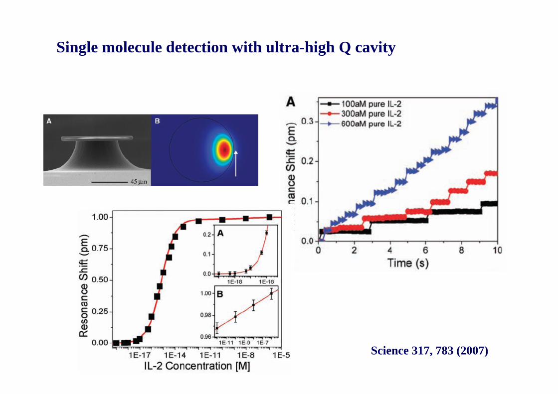
Single molecule detection with ultra-high Q cavity
Science 317, 783 (2007)

2πRn=mλ
whispering gallery modes (WGM)
Directional emissionDirectional emission
Stable WGM:Tunneling leakageWeak outputpoor directionality
588 590 592 5944000
5000
6000
7000
8000
Inte
nsity
(a.u
.)
Wavelength (nm)
in water P
Chaotic WGM:Refractive leakageIntense output possible
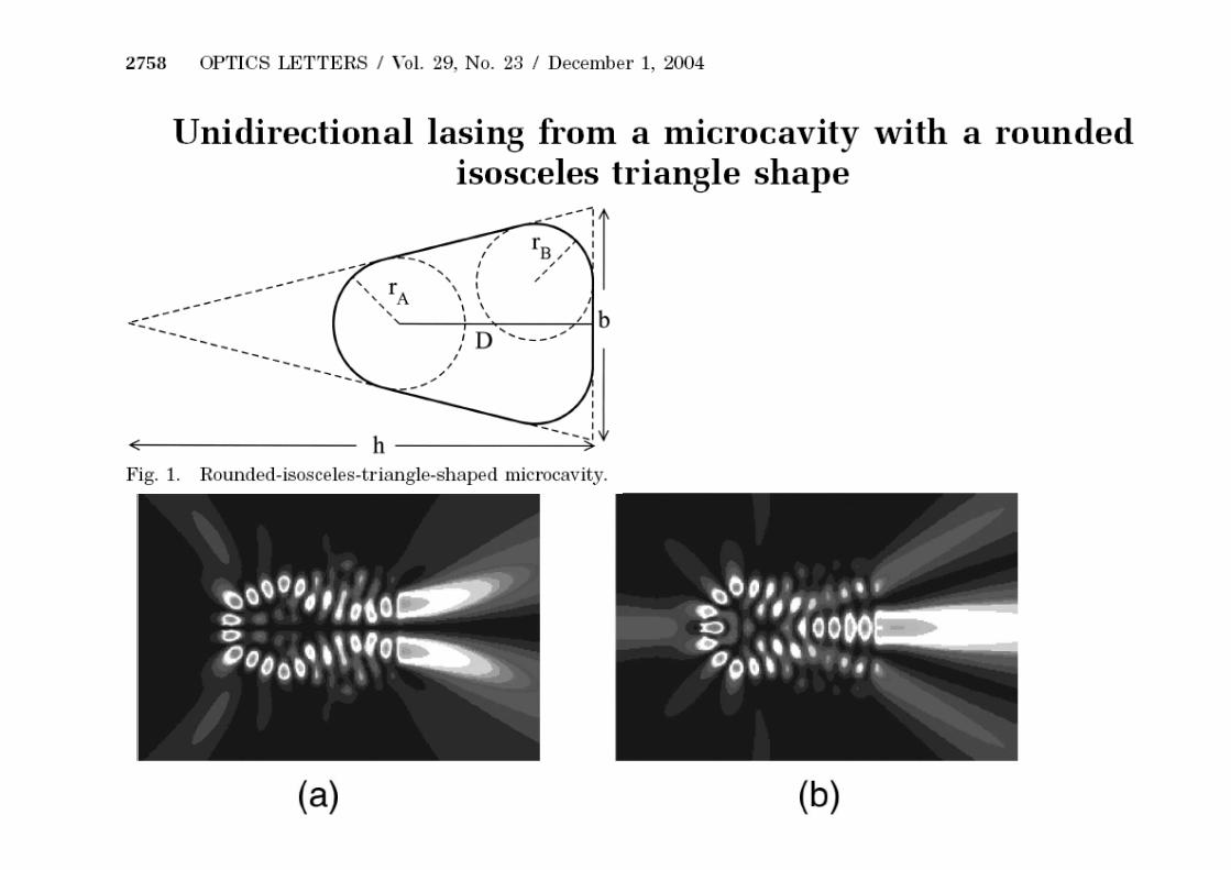
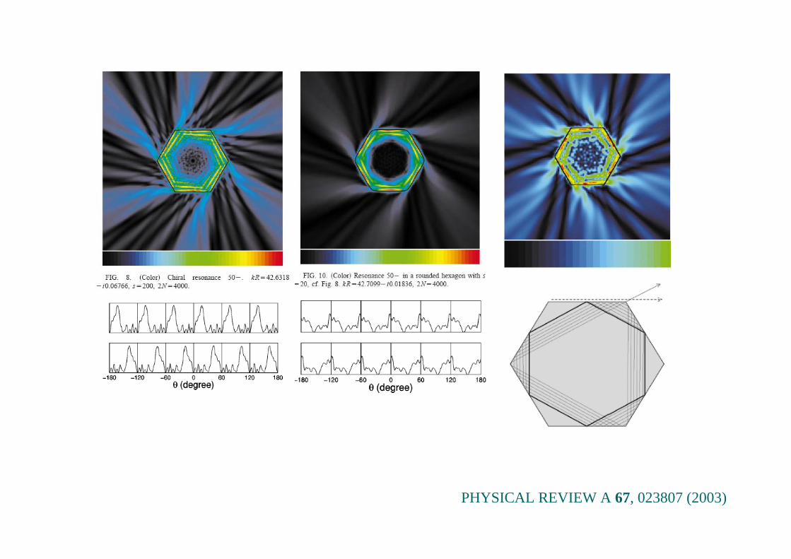
PHYSICAL REVIEW A 67, 023807 (2003)

Spiral-shaped cavity
Appl.Phys.Lett. 84(14) 2004

Physical Review Letters 100, 033901 (2008)Applied Physics Letters 94, 251101 (2009)
))cos(1()( 0 ϕεϕ += RR
Combining high Q and directional emission
Limacon type cavity
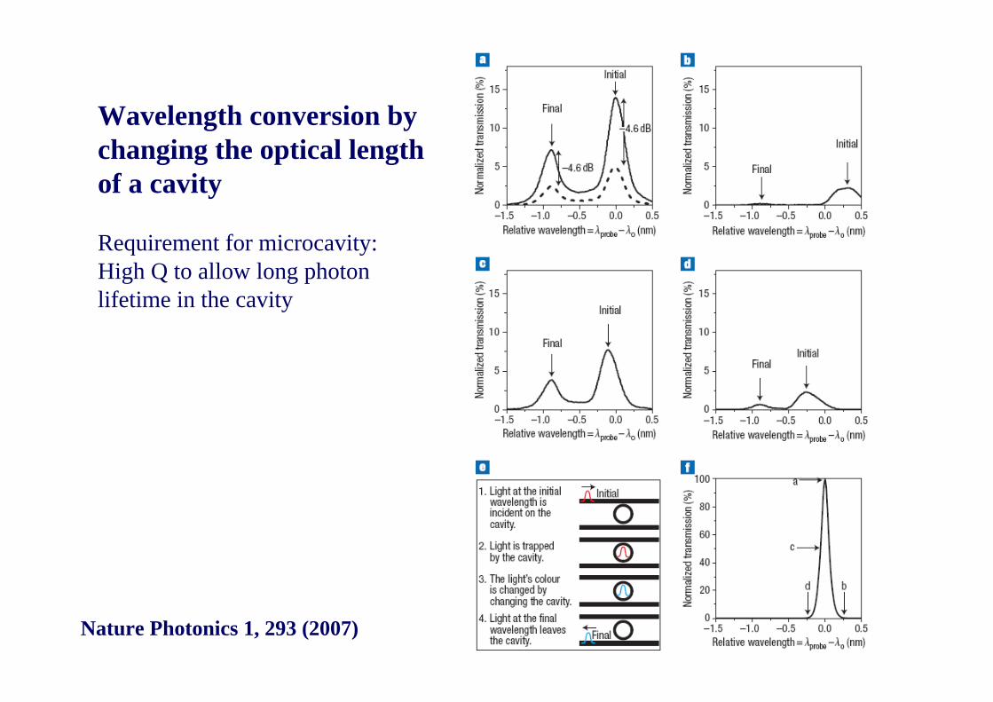
Wavelength conversion by changing the optical length of a cavity
Requirement for microcavity:High Q to allow long photon lifetime in the cavity
Nature Photonics 1, 293 (2007)
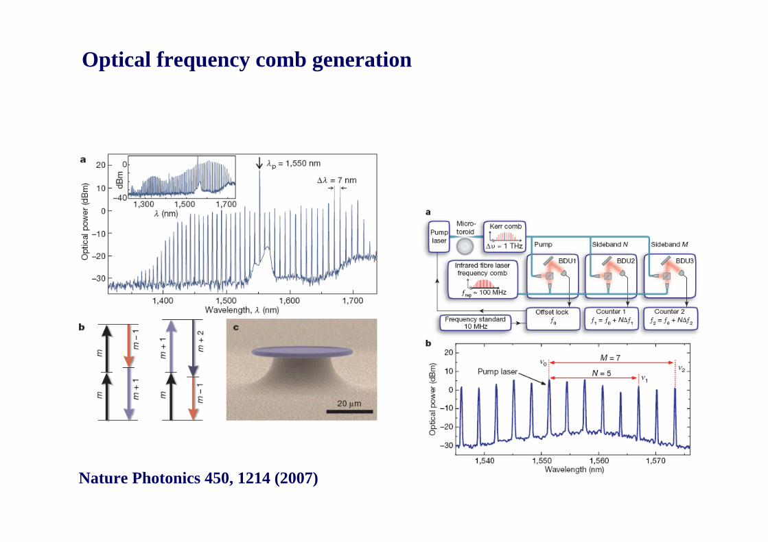
Optical frequency comb generation
Nature Photonics 450, 1214 (2007)

Frequency comb: 频率梳 Nobel prize 2007bring together ultrafast and ultra-precision
f = mf0 + foffset

Optical buffer with coupled microcavities
Nature Photonics 1, 65 (2007)

High Q surface plasmon polariton whispering gallery modes
Nature 457, 455 (2009)
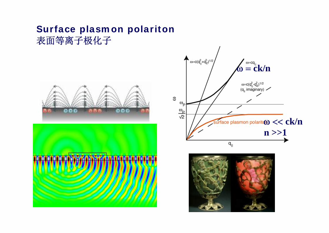
ω = ck/n
ω << ck/nn >>1
Surface plasmon polariton表面等离子极化子

Opto-mechanics
Photo-energy/
Mechanical energy
conversion
Cool the microcavity to μK
(ground state of mechanical vibration)

Our worksOur works

C C O
O
Si
OC3H
OC3H
OC3H
(CH2)3H2C
H3C
SiO2PMMA
Zr OC3H8
ZrO2
Photo-induced polymerization
MAPTMS ZPO
Easy to prepare thin films of excellent optical quality
Easy control of refractive index
Versatile doping to obtain photonic materials (active, nonlinearoptical, …
Our approach: Organic-inorganic Materials
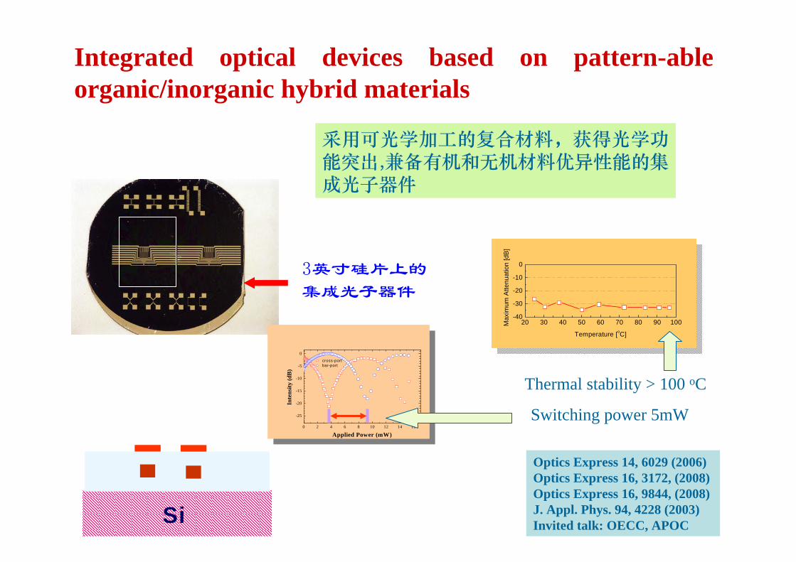
3英寸硅片上的集成光子器件
Integrated optical devices based on pattern-able organic/inorganic hybrid materials
Optics Express 14, 6029 (2006)Optics Express 16, 3172, (2008) Optics Express 16, 9844, (2008) J. Appl. Phys. 94, 4228 (2003) Invited talk: OECC, APOC
0 2 4 6 8 10 12 14 16
-25
-20
-15
-10
-5
0
cross-portbar-port
Inte
nsity
(dB
)
Applied Power (mW)
Switching power 5mW
20 30 40 50 60 70 80 90 100-40
-30
-20
-10
0
Temperature [oC]
Max
imum
Atte
nuat
ion
[dB
]
Thermal stability > 100 oC
采用可光学加工的复合材料,获得光学功能突出,兼备有机和无机材料优异性能的集成光子器件
Si
950 1000 1050 1100 1150 1200
-50
-40
-30
-20
-10
0
10
20
90 100 110 120 130 140 150
0
5
10
15
20
25
30
35
1051 1052 1053 1054 1055
-40
-30
-20
-10
0
10
Out
put P
ower
(dB
m)
Wavelength (nm)
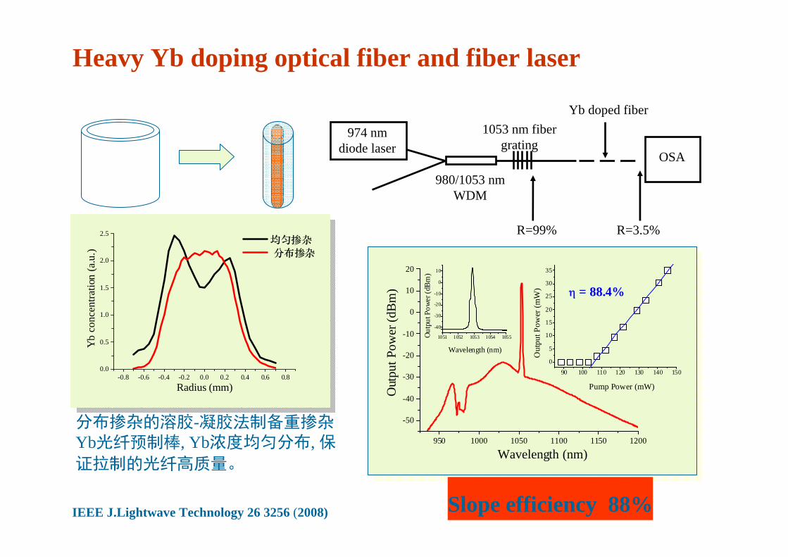
η = 88.4%
Out
put P
ower
(mW
)
Pump Power (mW)
Outp
ut P
ower
(dBm
)
Wavelength (nm)
-0.8 -0.6 -0.4 -0.2 0.0 0.2 0.4 0.6 0.80.0
0.5
1.0
1.5
2.0
2.5
Yb
conc
entra
tion
(a.u
.)
Radius (mm)
均匀掺杂 分布掺杂
974 nm diode laser
OSA
980/1053 nm WDM
1053 nm fiber grating
Yb doped fiber
R=99% R=3.5%
Heavy Yb doping optical fiber and fiber laser
分布掺杂的溶胶-凝胶法制备重掺杂Yb光纤预制棒, Yb浓度均匀分布, 保证拉制的光纤高质量。
IEEE J.Lightwave Technology 26 3256 (2008) Slope efficiency 88%
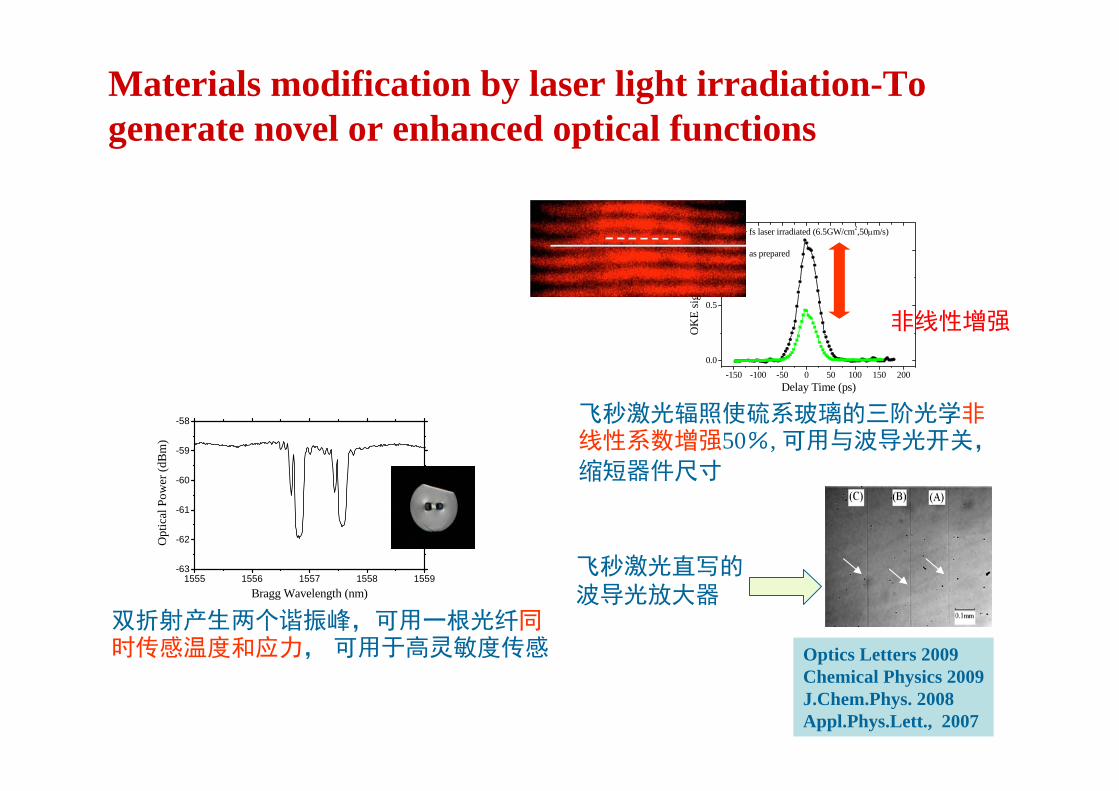
Materials modification by laser light irradiation-To generate novel or enhanced optical functions
Optics Letters 2009Chemical Physics 2009J.Chem.Phys. 2008Appl.Phys.Lett., 2007
-150 -100 -50 0 50 100 150 2000.0
0.5
1.0
OK
E si
gnal
(a.u
.)
Delay Time (ps)
fs laser irradiated (6.5GW/cm2,50μm/s)
as prepared
非线性增强
飞秒激光辐照使硫系玻璃的三阶光学非线性系数增强50%, 可用与波导光开关,
缩短器件尺寸
1555 1556 1557 1558 1559-63
-62
-61
-60
-59
-58
Opt
ical
Pow
er (d
Bm
)
Bragg Wavelength (nm)
双折射产生两个谐振峰,可用一根光纤同时传感温度和应力, 可用于高灵敏度传感
飞秒激光直写的波导光放大器

Directional Lasing From Extremely Deformed Directional Lasing From Extremely Deformed MicroMicro--cavitycavity
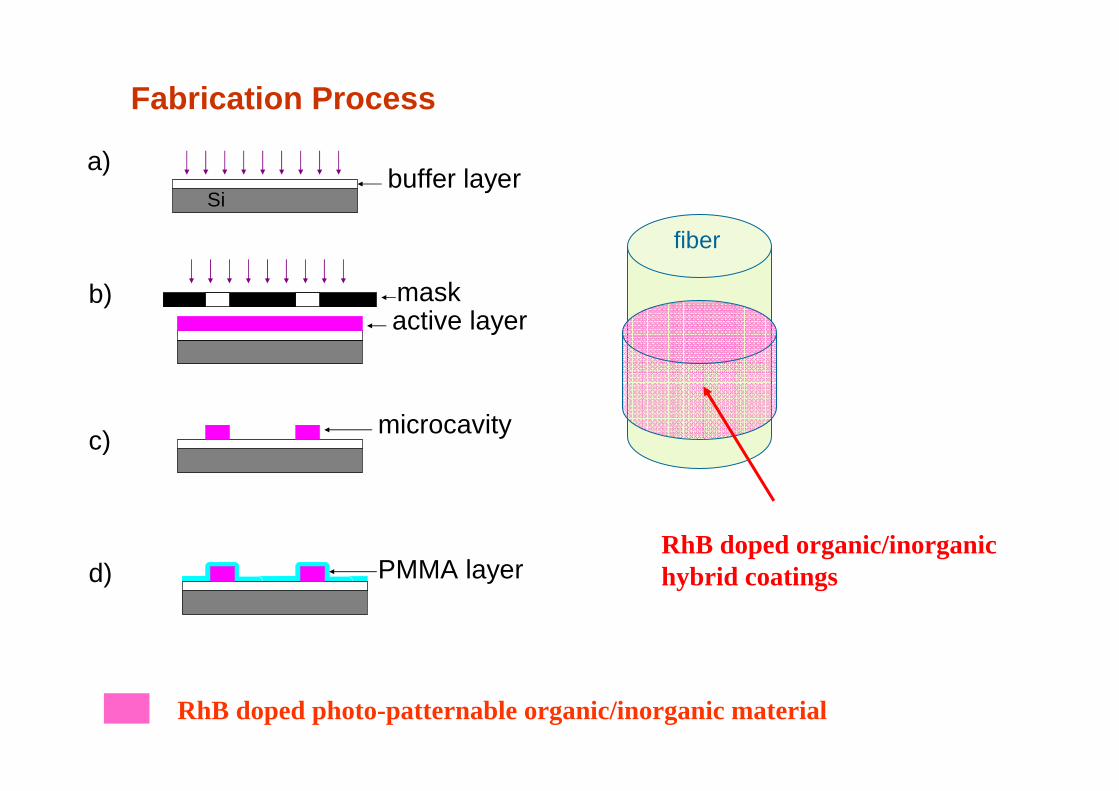
a)
b)
c)
d)
buffer layerSi
active layermask
PMMA layer
microcavity
Fabrication Process
RhB doped photo-patternable organic/inorganic material
RhB doped organic/inorganic hybrid coatings
fiber
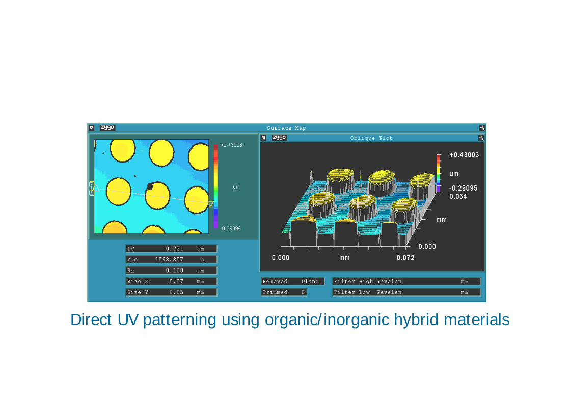
Direct UV patterning using organic/inorganic hybrid materials

Circular Disks and Square Disks

Improvement of Boundary Roughness after PMMA Coating
Bare disk Cladded disk
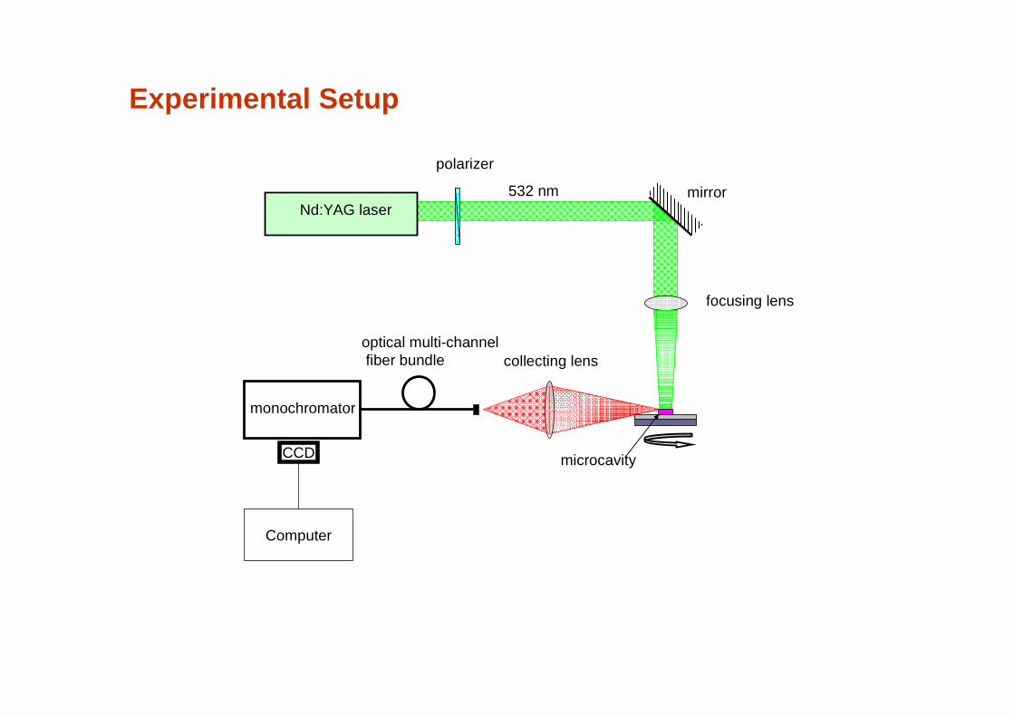
collecting lens
focusing lens
mirrorNd:YAG laser
532 nm
microcavity
optical multi-channelfiber bundle
monochromator
CCD
Computer
polarizer
Experimental Setup
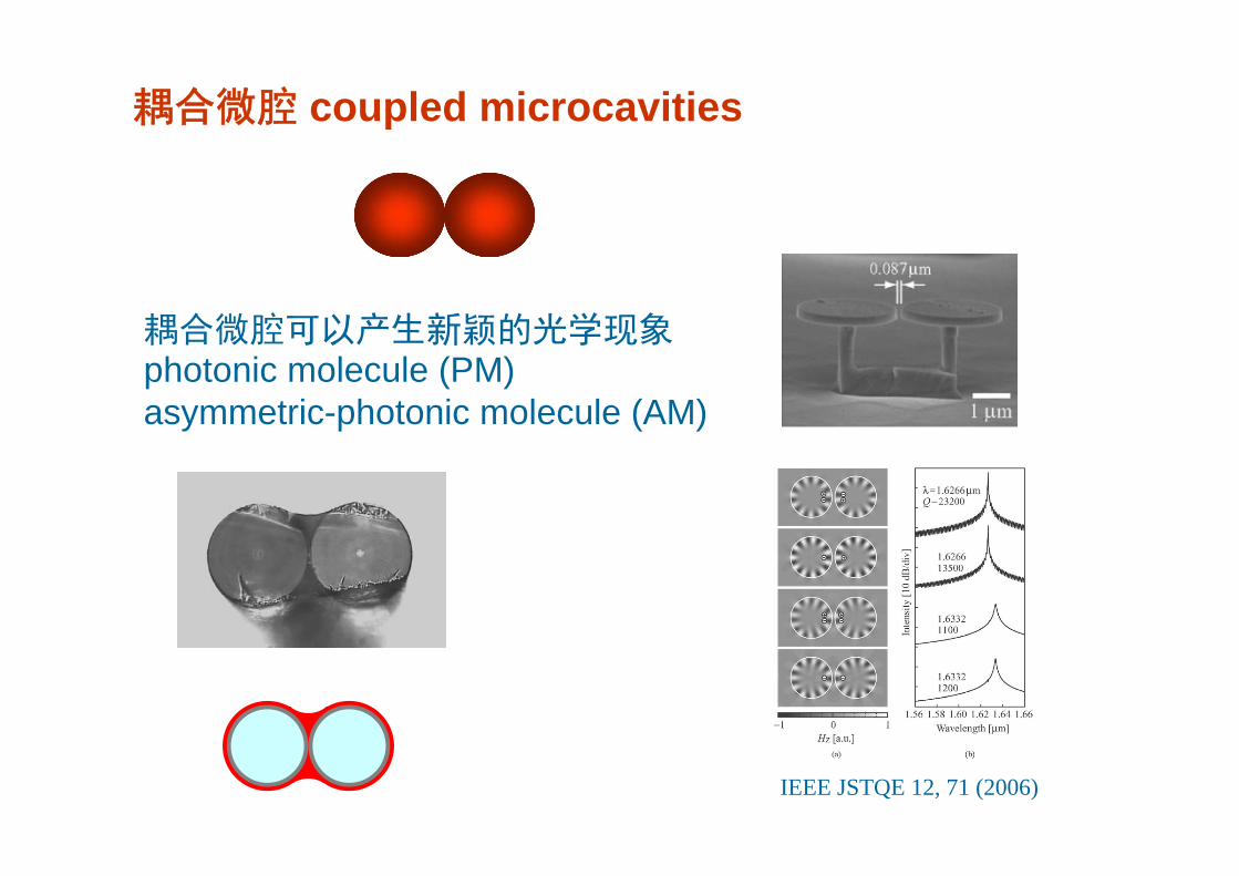
耦合微腔 coupled microcavities
耦合微腔可以产生新颖的光学现象photonic molecule (PM)asymmetric-photonic molecule (AM)
IEEE JSTQE 12, 71 (2006)
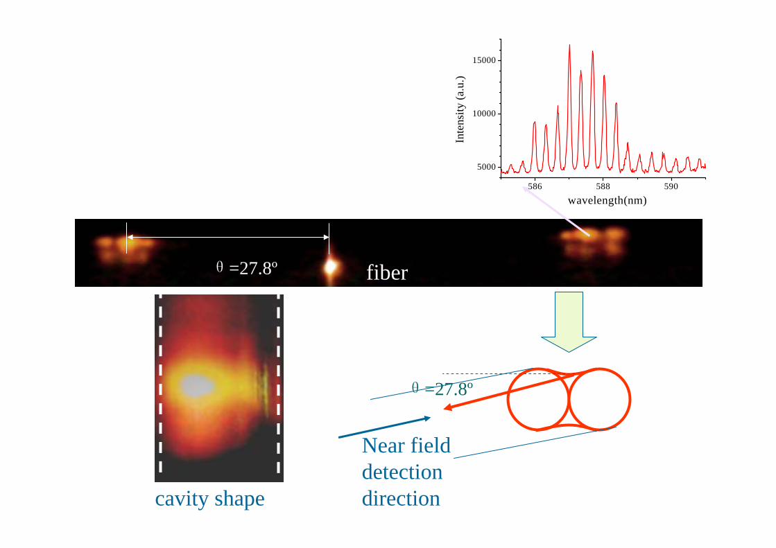
θ=27.8º
Near field detection direction
fiberθ=27.8º
cavity shape
586 588 590
5000
10000
15000
Inte
nsity
(a.u
.)
wavelength(nm)
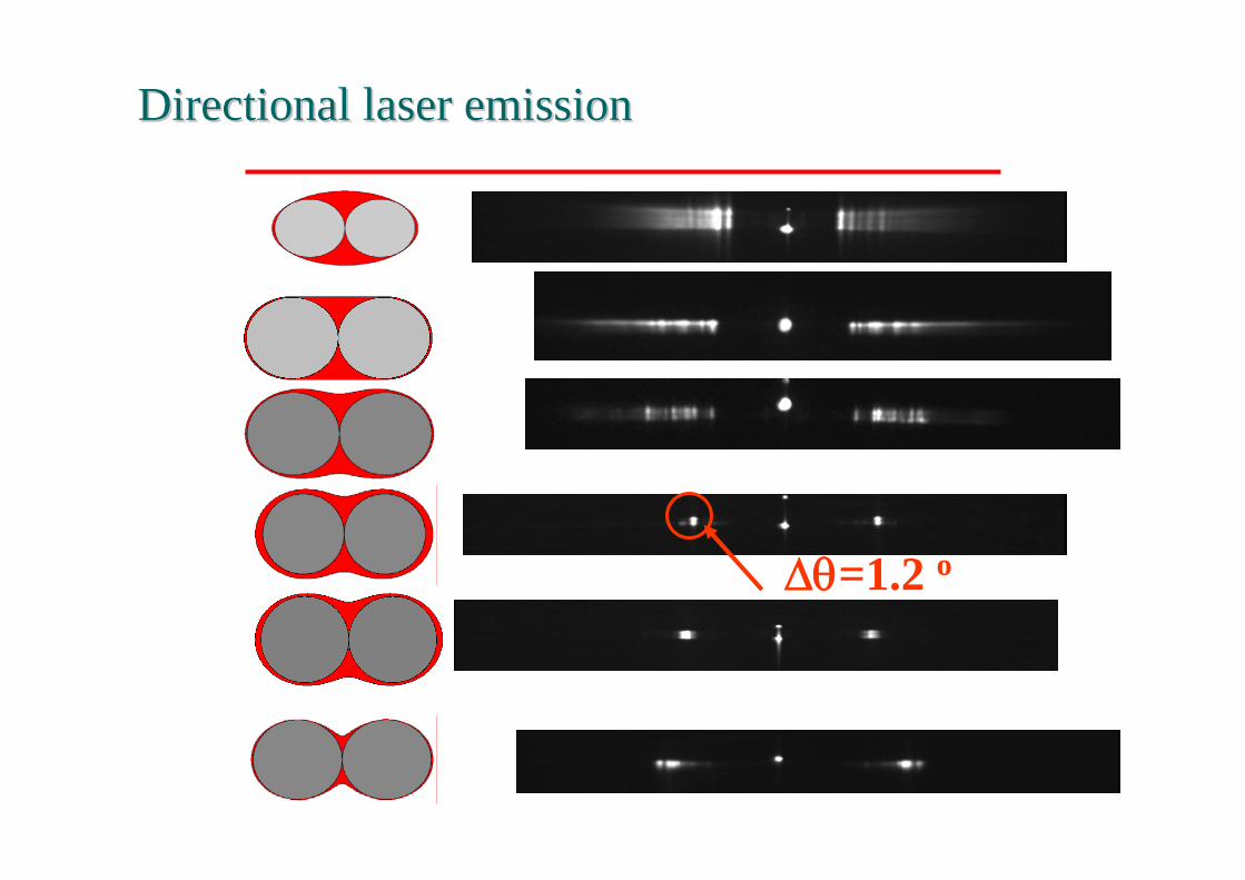
Directional laser emissionDirectional laser emission
Δθ=1.2 o

584 586 588 590 592
0.2
0.4
0.6
0.8
1.0
Nor
mal
ized
em
issi
on In
tens
ity
Wavelength (nm)0 60 120 180 240 300 360
0
5000
10000
15000
20000
25000
30000
35000
Emis
sion
Inte
nsity
(arb
.uni
t)
Emission angle θ (degree)
P
R
S 110o
30o
θ
L.Shang, et al., Appl.Phys.Lett., 92,071111 (2008)
extremely deformed microcavity

Single frequency whispering gallery mode laser

580 590 600 610 620 630 6400
50
100
150
200
250
Inte
nsity
(ar
b. u
nit)
Wavelength (nm)
R
eff
2
eff
Rn2
mRn2
πλλ
λπ
=Δ
=
Whispering gallery mode micro-ring laser
nm600nm40m50R
==Δ=
λλμ
@.
Much smaller than gain spectra
Smaller cavity Lower Q fabrication difficulties, electric & optical coupling
602 603 604 605 606 607 6080
50
100
150
200
250
Δλ
580 590 600 610 6200
6000
12000
Inte
nist
y (a
.u.)
Wavelength (nm)
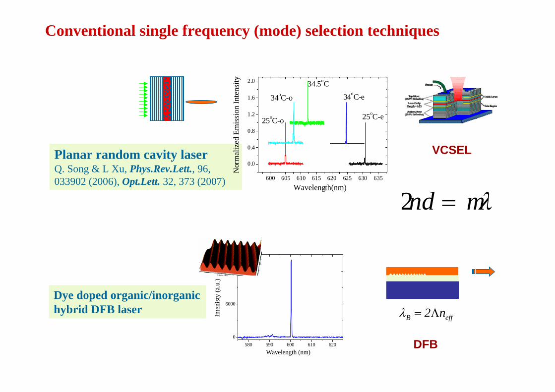
Planar random cavity laserQ. Song & L Xu, Phys.Rev.Lett., 96, 033902 (2006), Opt.Lett. 32, 373 (2007)
VCSEL
DFB
effB n2Λ=λDye doped organic/inorganic hybrid DFB laser
Conventional single frequency (mode) selection techniques
600 605 610 615 620 625 630 635
0.0
0.4
0.8
1.2
1.6
2.0
25oC-o
34oC-o
25oC-e
34oC-e
34.5oC
Nor
mal
ized
Em
issi
on In
tens
ity
Wavelength(nm)
λmnd =2

Composite cavity laser
游标效应 Vernier effect:
1/L1
1/L2
1/(L2-L1)
L2
L1
L1=L2+δ

Mode selection in asymmetric coupled microcavity laser
D2D1
620 621 622-300
0
300
600
900
1200
1500
Inte
nsity
(ar
b. u
nit)
Wavelength (nm)
small ring resonancelarge ring resonance
RhB doped organic/inorganic hybrid coatings
fiber fiber

fiber fiber
dye/hybridcoating
Hybrid coating
Monochromator
CCD

580 590 600 610 620 630 6400
50
100
150
200
250
Inte
nsity
(ar
b. u
nit)
Wavelength (nm)
a
580 590 600 610 6200
200
400
600
800
1000
1200
Inte
nsity
(arb
.uni
t)
Wavelength (nm)
c
590 600 610 620 6300
100
200
300
400
500
Inte
nsity
(arb
.uni
t)
Wavelength (nm)
b
)( 21eff
2
DDn −≈Δ
πλλ
Modulation width
Neff=1.5, D=125μm, ΔD=6μmΔλ=10 nm
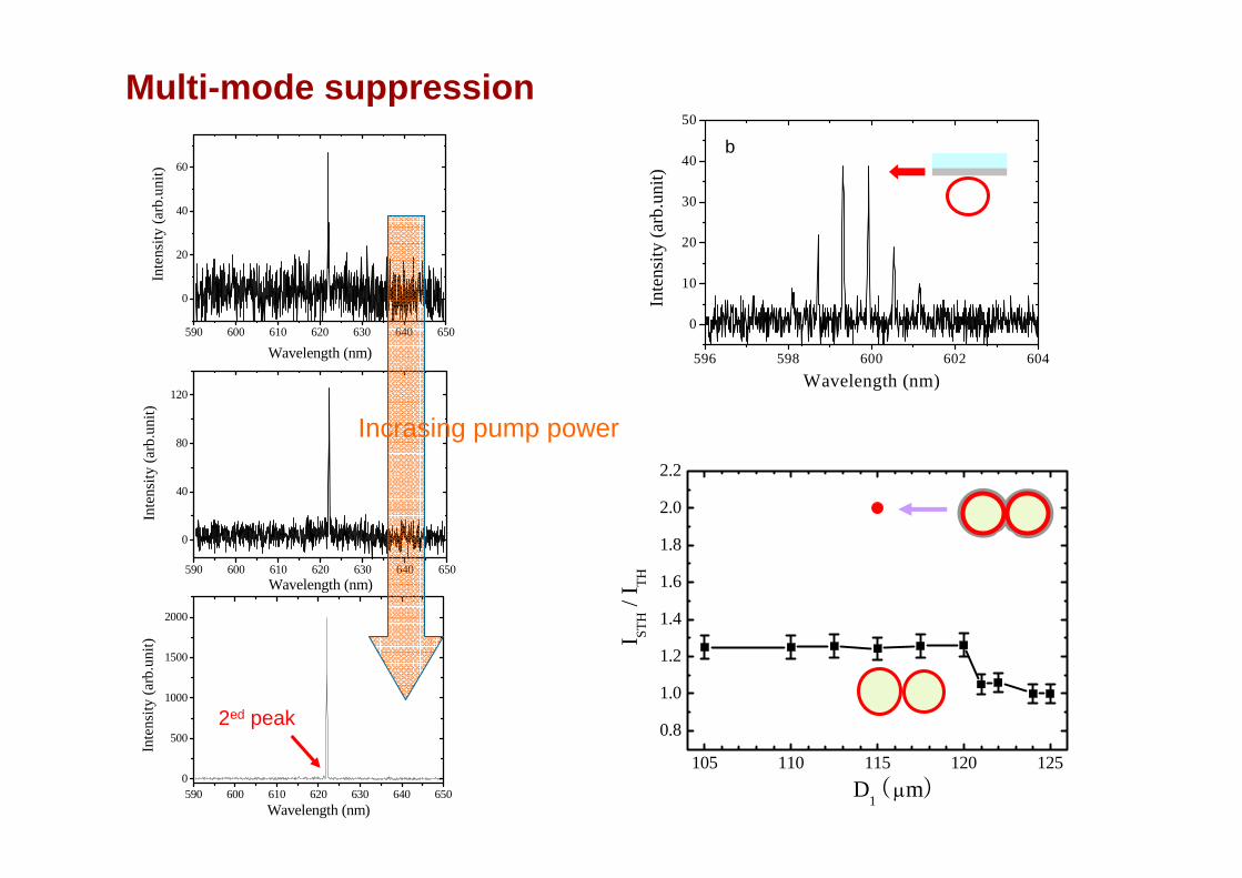
Modulated emission spectrum from coupled cavities
D2D1
105 110 115 120 125
0.8
1.0
1.2
1.4
1.6
1.8
2.0
2.2
I STH /
I TH
D1 (μm)
Multi-mode suppression
590 600 610 620 630 640 650
0
20
40
60
Inte
nsity
(arb
.uni
t)
Wavelength (nm)
590 600 610 620 630 640 650
0
40
80
120
Inte
nsity
(arb
.uni
t)
Wavelength (nm)
590 600 610 620 630 640 6500
500
1000
1500
2000
Inte
nsity
(arb
.uni
t)
Wavelength (nm)
2ed peak
Incrasing pump power
596 598 600 602 604
0
10
20
30
40
50
Inte
nsity
(arb
.uni
t)
Wavelength (nm)
b

Angular emission
0 50 100 150 200 250 300 3500
50
100
150
200
250
300
350
400
Inte
nsity
(arb
.uni
t)
Emission Angle (degree)
J.Ryu, PRA 74, 013804 (2006)
Near field pattern Far-field pattern
θ

Tapered fiber coupled single frequency coupled microcavity laser
620 622 624 626 628 630
0
100
200
300
400
Inte
nsity
(arb
.uni
t)
Wavelength (nm)
620 622 624 626 628 630
0
40
80
120
In
tens
ity (a
rb.u
nit)
Wavelength (nm)
Tapered fiber 1.5 μm
APM
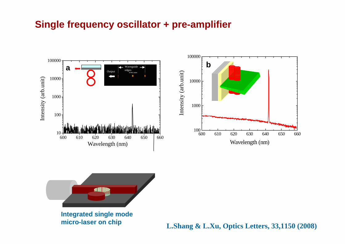
600 610 620 630 640 650 66010
100
1000
10000
100000
Inte
nsity
(arb
.uni
t)
Wavelength (nm)
aOutput
Waveguide edges
600 610 620 630 640 650 660100
1000
10000
100000
Inte
nsity
(arb
.uni
t)
Wavelength (nm)
b
Single frequency oscillator + pre-amplifier
Integrated single mode micro-laser on chip L.Shang & L.Xu, Optics Letters, 33,1150 (2008)

Toward a unidirectional single frequency laser on chip
Spiral cavity
G.D.Chern et al,, APL 83,1710 (2003)
G.D.Chern, et al., Opt. Lett. 32, 1093 (2007)
A coupled spiral cavity
)/()( πεφφ 21RR 0 +=

0
30
6090
120
150
180
210
240270
300
330
580 590 600 610 6200
20
40
60
80
100
120
140
160
180
0 40 80 120 160 200 240 2800
500
1000
1500
2000
Inte
nsity
(a.u
.)
Pumped Power Density (μJ/cm2)
Inye
nsity
(a.u
.)
Wavelength (nm)
TE TM
a
Unidirectioanl emission from Spiral microcavities
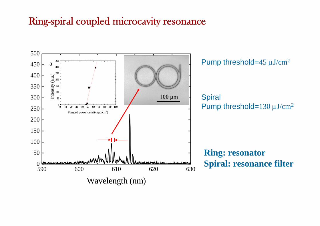
590 600 610 620 6300
50
100
150
200
250
300
350
400
450
500
0 10 20 30 40 50 60 70 80 90 1000
50
100
150
200
250
300
350
Inte
nsity
(a.u
.)
Pumped power density (μJ/cm2)
Wavelength (nm)
a
Pump threshold=45 μJ/cm2
SpiralPump threshold=130 μJ/cm2
Ring: resonatorSpiral: resonance filter
Ring-spiral coupled microcavity resonance

600 605 610 615 620 625
0
10
20
30
40
50
60
Inte
nsity
(a.u
.)
Wavelength (nm)
forward backward
600 605 610 615 620 6250
50
100
150
200
Inte
nsity
(a.u
.)
Wavelength (nm)
forward backward
0
30
6090
120
150
180
210
240270
300
330
Uni-directional single mode lasing
Incrasing pump power
X.Wu & L.Xu, Appl.Phys.Lett. 93, 081105 (2008)

Single mode microcavity laser: possible applications
UV single mode laser: difficulty in conventioanl cavity fabrication (DBR)
Optical sensing
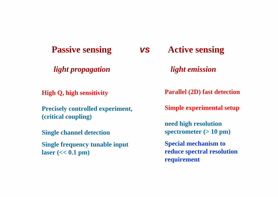
Passive sensing vs Active sensing
light propagation light emission
High Q, high sensitivity
Precisely controlled experiment, (critical coupling)
Single channel detection
Single frequency tunable input laser (<< 0.1 pm)
Parallel (2D) fast detection
Simple experimental setup
need high resolution spectrometer (> 10 pm)
Special mechanism to reduce spectral resolution requirement

Coupling variation induced ultrahigh sensitive label free bio-sensor by using single mode coupled microcavity laser
H Li & L. Xu, JACS 131,16612 (2009)
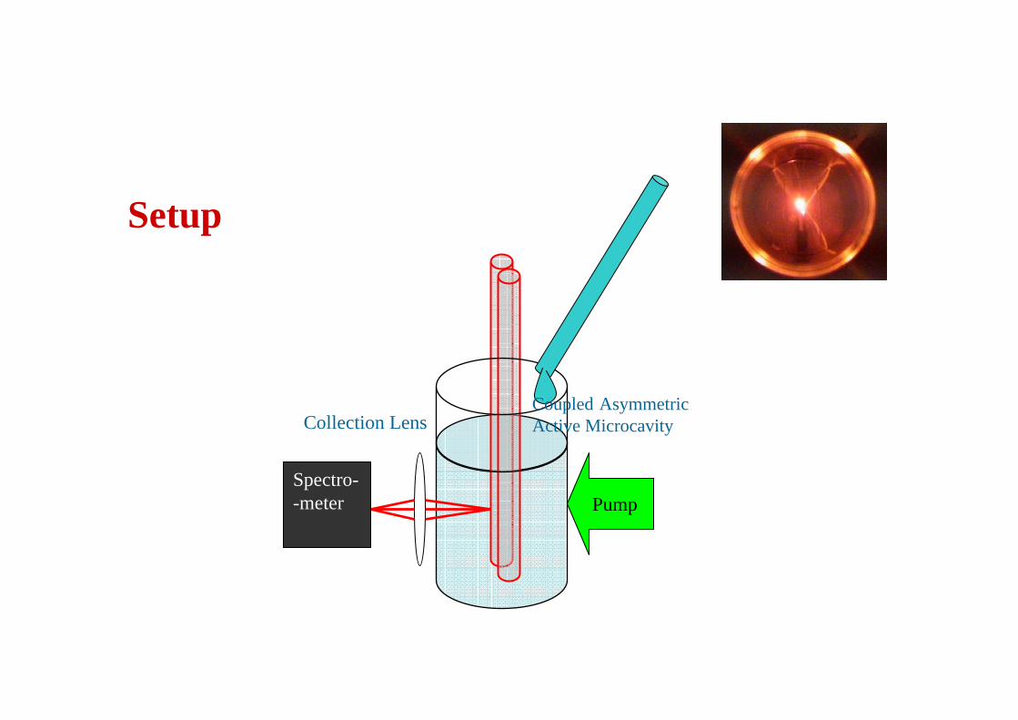
Setup
PumpSpectro--meter
Coupled Asymmetric Active MicrocavityCollection Lens

• Resonance shift vs hopping
1.345 1.350 1.355 1.360
623.75
623.80
623.85
623.90
623.95
624.00
Wav
elen
gth
(nm
)
Refrective Index1.3380 1.3383 1.3386 1.3389
-0.8
-0.4
0.0
0.4
0.8
ln(I
hopp
ed/I or
igin
al)
Refractive Index

Bio-sensing result
480pg/mL
80pg/mL
No BSA
Hopped mode
Wavelength
600 601 602 60
5648
4032
2416
BSA Con.(ng/mL) Wavelength(nm)8
0 10 20 30 40 50 60 70 80 90-3.6-3.0-2.4-1.8-1.2-0.60.00.61.21.82.43.0
BSA Lysozyme Goat IgG FITC-BSAln
(Iho
pped
/I orig
inal)
Concentration of BSA Solution (ng/mL)
Minimum observable BSA concentration80 pg/ml

Conventional sensing Coupling sensing
High RI agent
RI change sensing vs coupling variation sensing

Sticking of bio sample in the coupling region changes coupling coefficient
Reason of mode hopping
Imaging of fluorescent protein (cypet, FIRC-BSA)
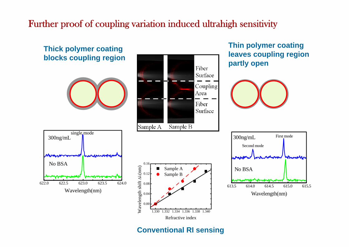
613.5 614.0 614.5 615.0 615.5
Wavelength(nm)
No BSA
Second mode
First mode300ng/mL
622.0 622.5 623.0 623.5 624.0
Wavelength(nm)
No BSA
300ng/mLsingle mode
Thick polymer coating blocks coupling region
Thin polymer coating leaves coupling region partly open
1.330 1.332 1.334 1.336 1.338 1.340
0.00
0.04
0.08
0.12
0.16
Wav
elen
gth
shift
Δλ(
nm)
Refractive index
Sample A Sample B
Conventional RI sensing
Further proof of coupling variation induced ultrahigh sensitivity