Embed Size (px)
Citation preview
NVMS-5000
User Manual
NVMS-5000 User Manual
Contents
1 Introduction .............................................................................................................................................................. 1
1.1 NVMS-5000 Brief Introduction......................................................................................................................... 1
1.1.1 Summerization ........................................................................................................................................ 1
1.1.2 Software Architecture ............................................................................................................................. 1
1.2 System Components .......................................................................................................................................... 2
1.2.1 System ..................................................................................................................................................... 2
1.2.2 Front-end Access ..................................................................................................................................... 2
1.2.3 Background Monitor ............................................................................................................................... 2
1.2.4 Control Center ......................................................................................................................................... 2
1.3 NVMS-5000 Version Introduction ..................................................................................................................... 3
2 Configuration Requirement .................................................................................................................................... 4
2.1 Software and Hardware Configuration Requirement ........................................................................................ 4
2.1.1 S&H Config Requirement for Contorl Center ........................................................................................ 4
2.1.2 S&H Config Requirement for Background Monitor............................................................................... 4
2.2 Requirement for Firewall ................................................................................................................................... 4
2.3 Confirm Installation Environment ..................................................................................................................... 5
3 Install and Uninstall the Software .......................................................................................................................... 6
3.1 Install the software ............................................................................................................................................. 6
3.1.1 Install Authentication Server ................................................................................................................... 6
3.1.2 Install Media Transfer Server ................................................................................................................ 11
3.1.3 Install Client .......................................................................................................................................... 13
3.2 Uninstall the software ...................................................................................................................................... 14
4 System Configuration ............................................................................................................................................ 16
4.1 Authentication Server ...................................................................................................................................... 16
4.2 Configuration Management Center ................................................................................................................. 17
4.3 Device Settings ................................................................................................................................................ 21
4.3.1 Create Area............................................................................................................................................ 21
4.3.2 Add Device ........................................................................................................................................... 21
4.4 Media Server Settings ...................................................................................................................................... 25
4.4.1 Create Media Server ............................................................................................................................. 25
4.4.2 Modify the Media Server of the Device ................................................................................................ 26
4.4.3 Start Media Server ................................................................................................................................ 27
4.5 Storage Server Settings .................................................................................................................................... 28
4.5.1 Add Storage Server ............................................................................................................................... 28
4.5.2 Add Channels to Storage Server ........................................................................................................... 29
NVMS-5000 User Manual
4.5.3 Setup Record Schedule ......................................................................................................................... 29
4.5.4 IP-SAN Configuration .......................................................................................................................... 30
4.6 Alarm Server Settings ...................................................................................................................................... 35
4.6.1 Alarm Linkage Settings ........................................................................................................................ 35
4.6.2 Alarm Schedule Setting ........................................................................................................................ 37
4.6.3 Alarm Status.......................................................................................................................................... 38
4.7 Schedule Settings ............................................................................................................................................. 39
4.7.1 Create Schedule .................................................................................................................................... 39
4.7.2 Modify or Delete Schedule ................................................................................................................... 39
4.7.3 Set Shedule for All Applications ........................................................................................................... 41
4.8 Decoder Settings .............................................................................................................................................. 41
4.9 E-Map Server ................................................................................................................................................... 41
4.9.1 Create E-Map ........................................................................................................................................ 42
4.9.2 Modify the Map and Add HotSpot and HotZone .................................................................................. 42
4.9.2.1 Modify Map ............................................................................................................................... 42
4.9.2.2 Add HotZone .............................................................................................................................. 43
4.9.2.3 Add HotSpot ............................................................................................................................... 44
4.10 User and Permission ........................................................................................................................................ 44
4.10.1 Add User ............................................................................................................................................... 45
4.10.2 Modify User Permission ....................................................................................................................... 45
4.10.3 Manage Online Users ............................................................................................................................ 47
4.11 System and Security ........................................................................................................................................ 47
5 NVMS-5000 Client ................................................................................................................................................. 49
5.1 Monitor Client ................................................................................................................................................. 49
5.1.1 Start Monitor Client .............................................................................................................................. 49
5.1.2 Group and Scheme Setting .................................................................................................................... 51
5.1.2.1 Channel Group Setting ............................................................................................................... 51
5.1.2.2 Group Dwell Scheme Setting ..................................................................................................... 52
5.1.3 Live and Alarm Preview ....................................................................................................................... 53
5.1.3.1 Live Preview .............................................................................................................................. 53
5.1.3.2 Alarm Preview ........................................................................................................................... 57
5.1.4 Multi-screen Display ............................................................................................................................. 58
5.1.5 Playback ................................................................................................................................................ 59
5.1.5.1 Playback Mode ........................................................................................................................... 61
5.1.5.2 Take Snapshot When Playback .................................................................................................. 64
5.1.5.3 Clip and Backup Record ............................................................................................................ 64
5.1.5.4 Download Record ....................................................................................................................... 64
5.1.6 Device Setting ....................................................................................................................................... 65
5.1.7 E-Map ................................................................................................................................................... 66
NVMS-5000 User Manual
5.1.8 System Log ........................................................................................................................................... 66
5.1.9 Basic Setting ......................................................................................................................................... 67
5.1.9.1 Video Path Setting ...................................................................................................................... 67
5.1.9.2 System Startup and Maintenance ............................................................................................... 68
5.2 Web Client ....................................................................................................................................................... 68
5.2.1 Operating Environment of Web Client .................................................................................................. 68
5.2.2 Start IE Client ....................................................................................................................................... 68
5.3 TV Wall Client ................................................................................................................................................. 70
5.3.1 Start TV Wall Client .............................................................................................................................. 70
5.3.2 TV Wall Output ..................................................................................................................................... 71
5.3.3 Decoder Output ..................................................................................................................................... 74
5.3.4 Playback ................................................................................................................................................ 79
5.3.5 Setup ..................................................................................................................................................... 79
5.3.5.1 Create or Delete Channel Group ................................................................................................ 80
5.3.5.2 Create or Delete Output Scheme ................................................................................................ 81
5.3.5.3 Backup & Restore Settings of TV Wall Client ........................................................................... 82
6 Common NVMS-5000 Networking ...................................................................................................................... 84
6.1 Server Parameters Configuration ..................................................................................................................... 84
6.2 NVMS-5000 Networking in a Private Network Environment......................................................................... 86
6.3 NVMS-5000 Networking with One Network Operator ................................................................................... 86
6.3.1 Servers with the WAN Static IP Address and Devices with the WAN Dynamic IP Address ................ 86
6.3.2 Servers and Devices both with the WAN Dynamic IP Address ............................................................ 86
6.4 NVMS-5000 Networking with Multiple Network Operators .......................................................................... 87
6.5 Client Login via Different Network Environment ........................................................................................... 89
7 FAQ ......................................................................................................................................................................... 90
NVMS-5000 User Manual
1
1.1 NVMS-5000 Brief Introduction
1.1.1 Summerization
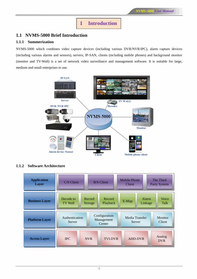
NVMS-5000 which combines video capture devices (including various DVR/NVR/IPC), alarm capture devices
(including various alarms and sensors), servers, IP-SAN, clients (including mobile phones) and background monitor
(monitor and TV-Wall) is a set of network video surveillance and management software. It is suitable for large,
medium and small enterprises to use.
1.1.2 Software Architecture
1 Introduction
Application
Layer
Business Layer
Platform Layer
Access Layer
C/S Client B/S Client Mobile Phone
Client
The Third
Party System
Decode to
TV Wall
Record
Storage
Record
Playback E-Map
Alarm
Linkage
Voice
Talk
Authentication
Server
Configuration
Management
Center
Media Transfer
Server
Monitor
Client
IPC NVR TVI-DVR AHD-DVR Analog
DVR
NVMS-5000 User Manual
2
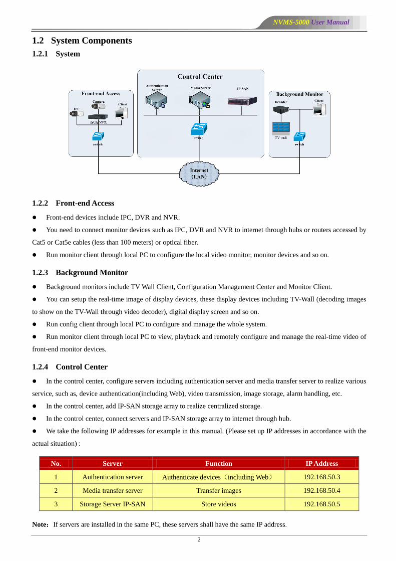
1.2 System Components
1.2.1 System
1.2.2 Front-end Access
Front-end devices include IPC, DVR and NVR.
You need to connect monitor devices such as IPC, DVR and NVR to internet through hubs or routers accessed by
Cat5 or Cat5e cables (less than 100 meters) or optical fiber.
Run monitor client through local PC to configure the local video monitor, monitor devices and so on.
1.2.3 Background Monitor
Background monitors include TV Wall Client, Configuration Management Center and Monitor Client.
You can setup the real-time image of display devices, these display devices including TV-Wall (decoding images
to show on the TV-Wall through video decoder), digital display screen and so on.
Run config client through local PC to configure and manage the whole system.
Run monitor client through local PC to view, playback and remotely configure and manage the real-time video of
front-end monitor devices.
1.2.4 Control Center
In the control center, configure servers including authentication server and media transfer server to realize various
service, such as, device authentication(including Web), video transmission, image storage, alarm handling, etc.
In the control center, add IP-SAN storage array to realize centralized storage.
In the control center, connect servers and IP-SAN storage array to internet through hub.
We take the following IP addresses for example in this manual. (Please set up IP addresses in accordance with the
actual situation) :
No. Server Function IP Address
1 Authentication server Authenticate devices(including Web) 192.168.50.3
2 Media transfer server Transfer images 192.168.50.4
3 Storage Server IP-SAN Store videos 192.168.50.5
Note:If servers are installed in the same PC, these servers shall have the same IP address.

NVMS-5000 User Manual
3
1.3 NVMS-5000 Version Introduction
Version Signal access on trial Average signal access Max signal access
NVMS-5000 v1.3.0 16 channels video signals 300-400 channels video
signals 30000-ch video signals

NVMS-5000 User Manual
4
2.1 Software and Hardware Configuration Requirement
2.1.1 S&H Config Requirement for Contorl Center
No. NVMS-5000
components
Recommendation for
hardware configuration
Recommendation for
software configuration Number
1
Authentication
Server
(including
Web
Server/Alarm
Server/E-Map
Server)
Inter(R) Core(TM)i3 3.40GHz
or above/4GB Memory/500GB
SATA/2×1000M NICs
Windows Server 2008
32bit/64bit
/Windows Server 2003
32bit/64bit
1
2 Media Server
Inter(R) Core(TM)i3 3.40GHz
or above/4GB Memory/500GB
SATA/2×1000M NICs
Windows Server 2008
32bit/64bit
/Windows Server 2003
32bit/64bit
It is up to the video
format and the number
of channel previewing
simultaneously
3 HDD Capacity :
500GB/1TB/2TB/3TB ——
It is up to the stream,
channel and time of the
storage video
4 IP-SAN Supports 12/16/24 SATAs —— It is up to the number of
the HDD
2.1.2 S&H Config Requirement for Background Monitor
No. NVMS-5000
components
Recommendation for hardware
configuration
Recommendation for
software configuration Number
1 Monitor Client
Intel Core i3 530 double core
2.93GHz or above/4GB DDR3/NV
GT430 or AMD HD 6570 or above,
above 512MB GDDR5 Memory
(recommend 1GB GDDR5 memory)
/500GB SATA/100M NIC
Windows 7 SP1 32bit/64bit
Professional/Ultimate
Windows 8 32bit/64bit
Professional
Windows 10 32bit/64bit
Professional
As required
by user
2
Configuration
Management
Center
TV Wall Client
CPU:2G or above
Memory:2GB DDR3
HDD:500GB SATA
NI:1000M
Windows 7 SP1 32bit/64bit
Professional/Ultimate
Windows 8 32bit/64bit
Professional
Windows 10 32bit/64bit
Professional
1
2.2 Requirement for Firewall
In order to ensure the network security, it is necessary for the system to setup firewall. All monitor ports shall be
opened in the installed servers. The open ports are as follows:
Server Port Type Port
Authentication Server Internal Port 6003
Web Server Service Port 8088
2 Configuration Requirement
NVMS-5000 User Manual
5
Server Port Type Port
Media Transfer Server Internal Port 6006
Auto Report Port 2009
Storage Server Internal Port 6009
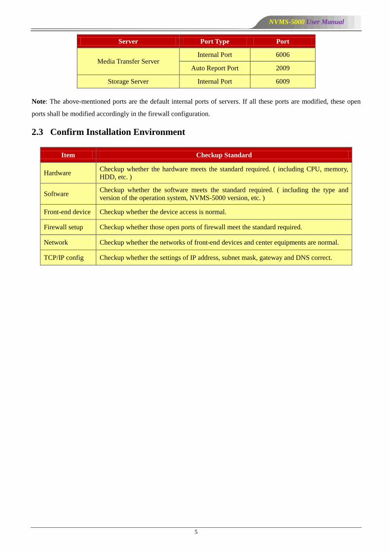
Note: The above-mentioned ports are the default internal ports of servers. If all these ports are modified, these open
ports shall be modified accordingly in the firewall configuration.
2.3 Confirm Installation Environment
Item Checkup Standard
Hardware Checkup whether the hardware meets the standard required. ( including CPU, memory,
HDD, etc. )
Software Checkup whether the software meets the standard required. ( including the type and
version of the operation system, NVMS-5000 version, etc. )
Front-end device Checkup whether the device access is normal.
Firewall setup Checkup whether those open ports of firewall meet the standard required.
Network Checkup whether the networks of front-end devices and center equipments are normal.
TCP/IP config Checkup whether the settings of IP address, subnet mask, gateway and DNS correct.

NVMS-5000 User Manual
6
3.1 Install the software
There are three setups, setup of Authentication Server, Media Transfer Server and Client.
3.1.1 Install Authentication Server
1) Find the ―setup.exe‖ file of Authentication Server. A welcome interface will pop up by double clicking it. Now
click ―Next‖ button to continue.
2) Select ―I accept the terms of the license agreement‖ and then click ―Next‖ button to continue.
3) Click ―Browse…‖ button to set the installation path and then click ―Next‖ button to continue.
3 Install and Uninstall the Software
NVMS-5000 User Manual
7
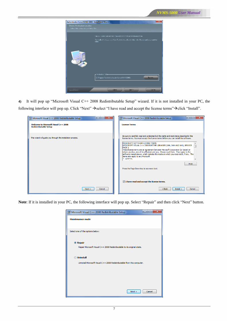
4) It will pop up ―Microsoft Visual C++ 2008 Redistributable Setup‖ wizard. If it is not installed in your PC, the
following interface will pop up. Click ―Next‖ select ―I have read and accept the license terms‖click ―Install‖.
Note: If it is installed in your PC, the following interface will pop up. Select ―Repair‖ and then click ―Next‖ button.
NVMS-5000 User Manual
8
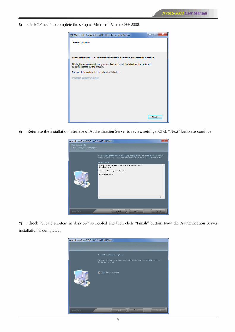
5) Click ―Finish‖ to complete the setup of Microsoft Visual C++ 2008.
6) Return to the installation interface of Authentication Server to review settings. Click ―Next‖ button to continue.
7) Check ―Create shortcut in desktop‖ as needed and then click ―Finish‖ button. Now the Authentication Server
installation is completed.

NVMS-5000 User Manual
9
8) After you finish installing Authentication Server, a wizard for Apache HTTP Server pops up. If you want to
access web client, please click ―Next‖ button to install.
9) Select ―I accept the terms in the license agreement‖, and then click ―Next‖ to continue.
10) Click ―Next‖ to continue.
NVMS-5000 User Manual
10
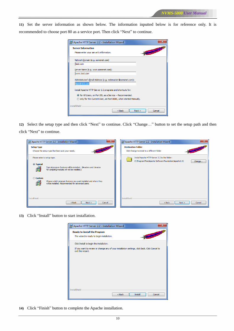
11) Set the server information as shown below. The information inputted below is for reference only. It is
recommended to choose port 80 as a service port. Then click ―Next‖ to continue.
12) Select the setup type and then click ―Next‖ to continue. Click ―Change…‖ button to set the setup path and then
click ―Next‖ to continue.
13) Click ―Install‖ button to start installation.
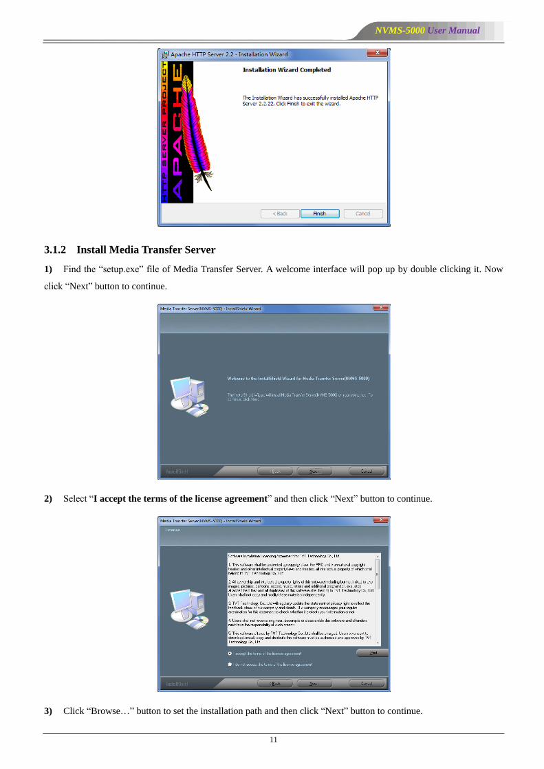
14) Click ―Finish‖ button to complete the Apache installation.
NVMS-5000 User Manual
11
3.1.2 Install Media Transfer Server
1) Find the ―setup.exe‖ file of Media Transfer Server. A welcome interface will pop up by double clicking it. Now
click ―Next‖ button to continue.
2) Select ―I accept the terms of the license agreement‖ and then click ―Next‖ button to continue.
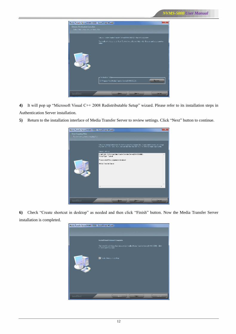
3) Click ―Browse…‖ button to set the installation path and then click ―Next‖ button to continue.
NVMS-5000 User Manual
12
4) It will pop up ―Microsoft Visual C++ 2008 Redistributable Setup‖ wizard. Please refer to its installation steps in
Authentication Server installation.
5) Return to the installation interface of Media Transfer Server to review settings. Click ―Next‖ button to continue.
6) Check ―Create shortcut in desktop‖ as needed and then click ―Finish‖ button. Now the Media Transfer Server
installation is completed.

NVMS-5000 User Manual
13
3.1.3 Install Client
1) Find the ―setup.exe‖ file of Client. A welcome interface will pop up by double clicking it. Now click ―Next‖
button to continue.
2) Select ―I accept the terms of the license agreement‖ and then click ―Next‖ button to continue.
3) Click ―Browse…‖ button to set the installation path and then click ―Next‖ button to continue.
NVMS-5000 User Manual
14
4) It will pop up ―Microsoft Visual C++ 2008 Redistributable Setup‖ wizard. Please refer to its installation steps in
Authentication Server installation.
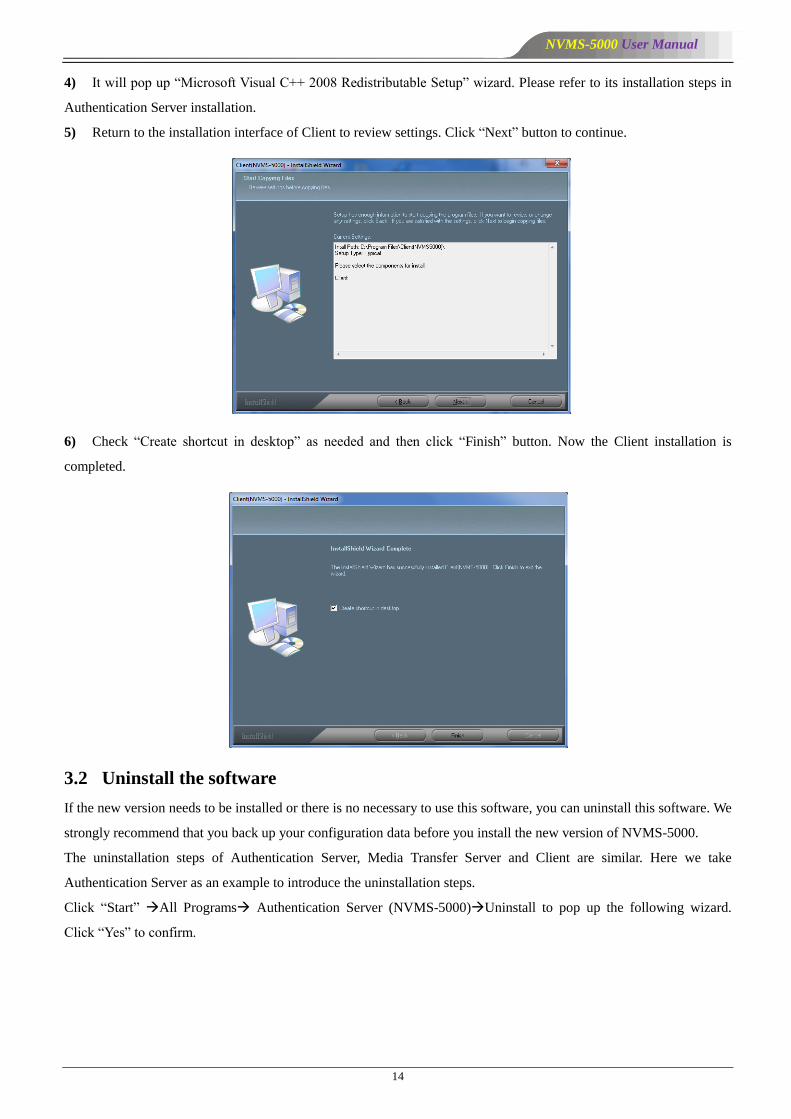
5) Return to the installation interface of Client to review settings. Click ―Next‖ button to continue.
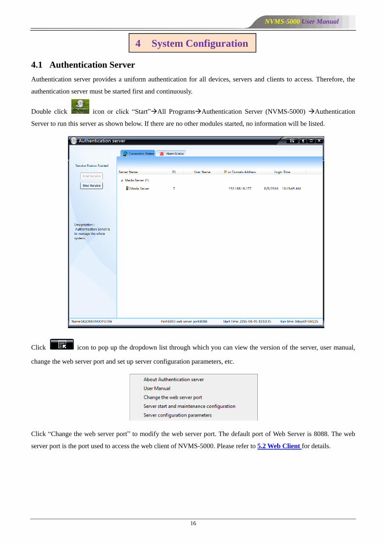
6) Check ―Create shortcut in desktop‖ as needed and then click ―Finish‖ button. Now the Client installation is
completed.
3.2 Uninstall the software
If the new version needs to be installed or there is no necessary to use this software, you can uninstall this software. We
strongly recommend that you back up your configuration data before you install the new version of NVMS-5000.
The uninstallation steps of Authentication Server, Media Transfer Server and Client are similar. Here we take
Authentication Server as an example to introduce the uninstallation steps.
Click ―Start‖ All Programs Authentication Server (NVMS-5000)Uninstall to pop up the following wizard.
Click ―Yes‖ to confirm.

NVMS-5000 User Manual
15
Then click ―Finish‖ button to completely uninstall Authentication Server.
If you have already installed the Apache HTTP Server, please go to Control Panel to uninstall it.
Click ―Start‖Control PanelProgramsPrograms and Features to go to the interface. Select the Apache HTTP
Server 2.2.22 in the program list and then click ―Uninstall‖ to start uninstallation.
NVMS-5000 User Manual
16
4.1 Authentication Server
Authentication server provides a uniform authentication for all devices, servers and clients to access. Therefore, the
authentication server must be started first and continuously.
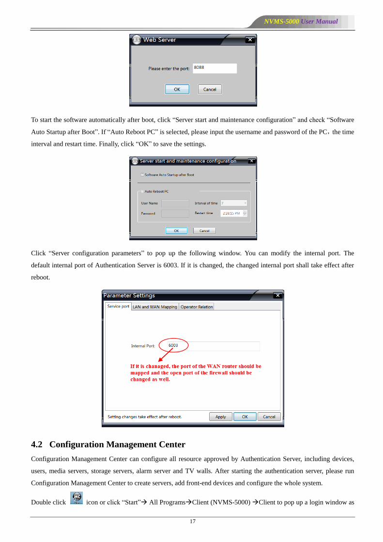
Double click icon or click ―Start‖All ProgramsAuthentication Server (NVMS-5000) Authentication
Server to run this server as shown below. If there are no other modules started, no information will be listed.
Click icon to pop up the dropdown list through which you can view the version of the server, user manual,
change the web server port and set up server configuration parameters, etc.
Click ―Change the web server port‖ to modify the web server port. The default port of Web Server is 8088. The web
server port is the port used to access the web client of NVMS-5000. Please refer to 5.2 Web Client for details.
4 System Configuration
NVMS-5000 User Manual
17
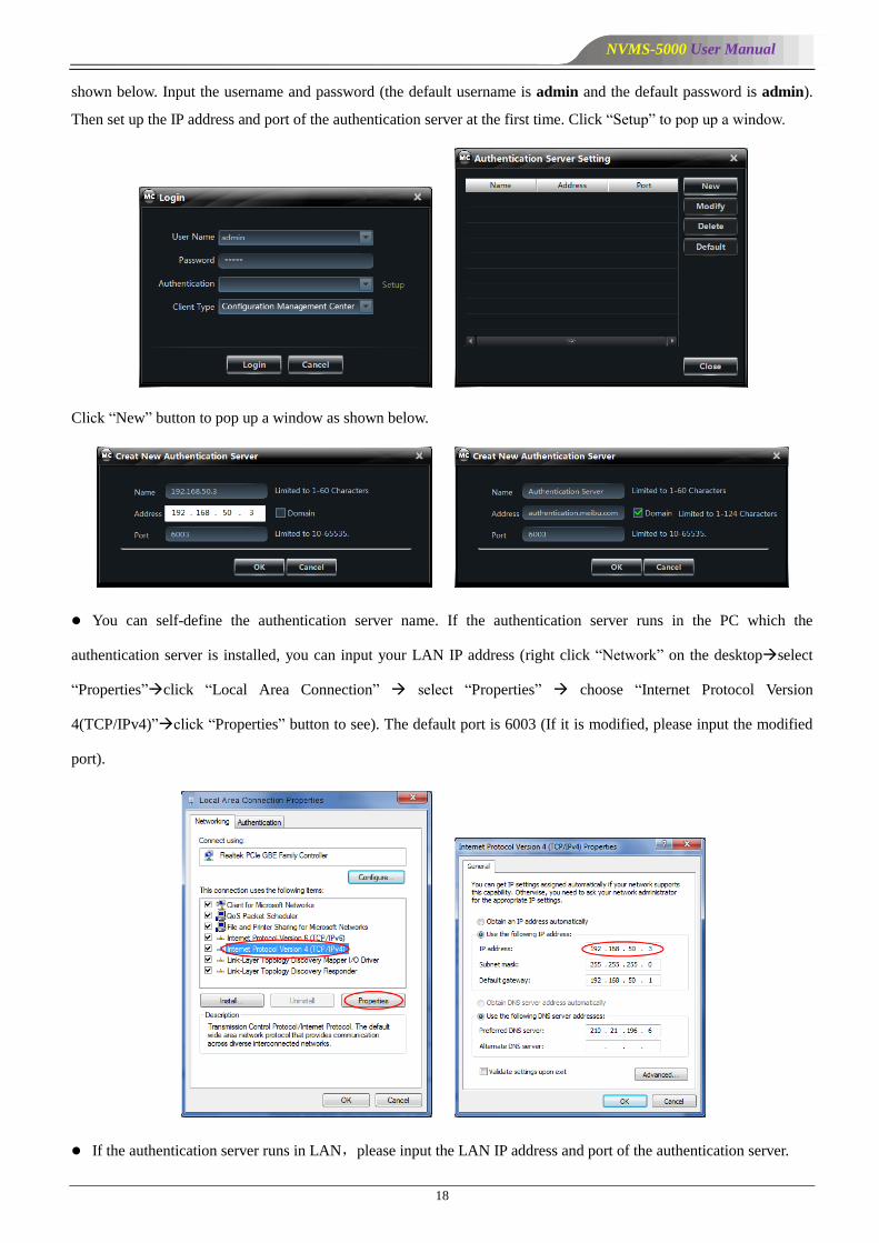
To start the software automatically after boot, click ―Server start and maintenance configuration‖ and check ―Software
Auto Startup after Boot‖. If ―Auto Reboot PC‖ is selected, please input the username and password of the PC,the time
interval and restart time. Finally, click ―OK‖ to save the settings.
Click ―Server configuration parameters‖ to pop up the following window. You can modify the internal port. The
default internal port of Authentication Server is 6003. If it is changed, the changed internal port shall take effect after
reboot.
4.2 Configuration Management Center
Configuration Management Center can configure all resource approved by Authentication Server, including devices,
users, media servers, storage servers, alarm server and TV walls. After starting the authentication server, please run
Configuration Management Center to create servers, add front-end devices and configure the whole system.
Double click icon or click ―Start‖ All ProgramsClient (NVMS-5000) Client to pop up a login window as
NVMS-5000 User Manual
18
shown below. Input the username and password (the default username is admin and the default password is admin).
Then set up the IP address and port of the authentication server at the first time. Click ―Setup‖ to pop up a window.
Click ―New‖ button to pop up a window as shown below.
You can self-define the authentication server name. If the authentication server runs in the PC which the
authentication server is installed, you can input your LAN IP address (right click ―Network‖ on the desktopselect
―Properties‖click ―Local Area Connection‖ select ―Properties‖ choose ―Internet Protocol Version
4(TCP/IPv4)‖click ―Properties‖ button to see). The default port is 6003 (If it is modified, please input the modified
port).
If the authentication server runs in LAN,please input the LAN IP address and port of the authentication server.
NVMS-5000 User Manual
19
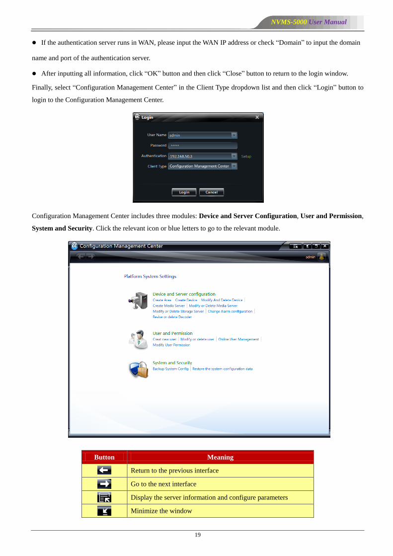
If the authentication server runs in WAN, please input the WAN IP address or check ―Domain‖ to input the domain
name and port of the authentication server.
After inputting all information, click ―OK‖ button and then click ―Close‖ button to return to the login window.
Finally, select ―Configuration Management Center‖ in the Client Type dropdown list and then click ―Login‖ button to
login to the Configuration Management Center.
Configuration Management Center includes three modules: Device and Server Configuration, User and Permission,
System and Security. Click the relevant icon or blue letters to go to the relevant module.
Button Meaning
Return to the previous interface
Go to the next interface
Display the server information and configure parameters
Minimize the window
NVMS-5000 User Manual
20
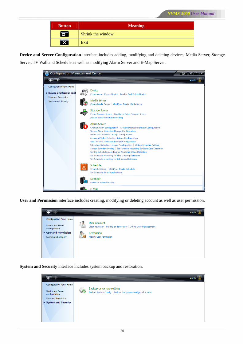
Button Meaning
Shrink the window
Exit
Device and Server Configuration interface includes adding, modifying and deleting devices, Media Server, Storage
Server, TV Wall and Schedule as well as modifying Alarm Server and E-Map Server.
User and Permission interface includes creating, modifying or deleting account as well as user permission.
System and Security interface includes system backup and restoration.
NVMS-5000 User Manual
21
4.3 Device Settings
Create area and add or delete device.
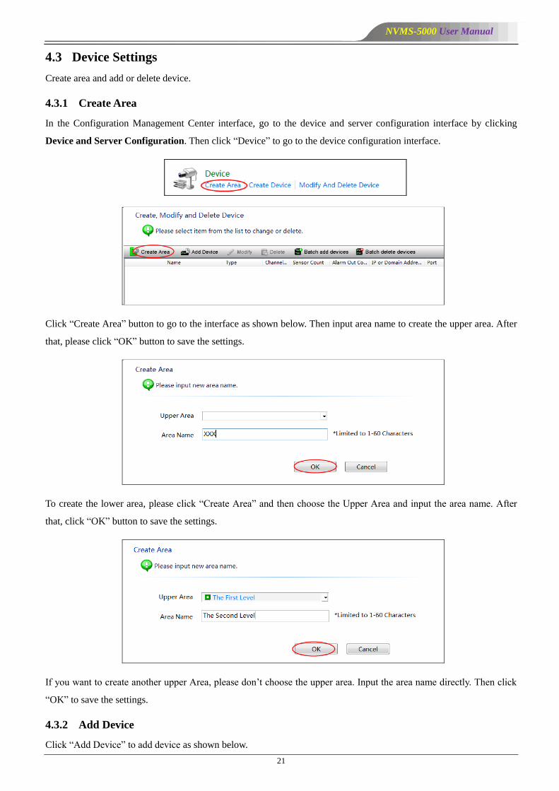
4.3.1 Create Area
In the Configuration Management Center interface, go to the device and server configuration interface by clicking
Device and Server Configuration. Then click ―Device‖ to go to the device configuration interface.
Click ―Create Area‖ button to go to the interface as shown below. Then input area name to create the upper area. After
that, please click ―OK‖ button to save the settings.
To create the lower area, please click ―Create Area‖ and then choose the Upper Area and input the area name. After
that, click ―OK‖ button to save the settings.
If you want to create another upper Area, please don’t choose the upper area. Input the area name directly. Then click
―OK‖ to save the settings.
4.3.2 Add Device
Click ―Add Device‖ to add device as shown below.
NVMS-5000 User Manual
22
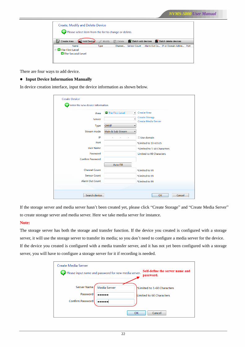
There are four ways to add device.
Input Device Information Manually
In device creation interface, input the device information as shown below.
If the storage server and media server hasn’t been created yet, please click ―Create Storage‖ and ―Create Media Server‖
to create storage server and media server. Here we take media server for instance.
Note:
The storage server has both the storage and transfer function. If the device you created is configured with a storage
server, it will use the storage server to transfer its media; so you don’t need to configure a media server for the device.
If the device you created is configured with a media transfer server, and it has not yet been configured with a storage
server, you will have to configure a storage server for it if recording is needed.

NVMS-5000 User Manual
23
After you create the media server, please return to the device creation interface to select a media server and then click
―OK‖ button to add the device.
Search Online Device
In device creation interface, a device list will pop up by clicking ―Search Device‖ button.
The device IP address, port and MAC address automatically on the same network area will list on the Search Device
window. You can double click the IP address which is on the same network segment as the authentication server’s. The
device type, stream mode, IP address and port will be added automatically. Then you just need to select area, server
and input device name, username and password. The channel count, sensor count and alarm out count will be
automatically filled by clicking ―Auto Fill‖ button.
Note:
The channel count, sensor count and alarm out count will be filled automatically by the system if the device type
belongs to private protocol.

NVMS-5000 User Manual
24
Auto Report
In device creation interface, select device type and checkmark ―Auto report‖ as shown below.
Select area, server and device type, input device number, channel count, sensor count and alarm out count. You also
need to configure the network of the device before the auto report takes effect (Please see the network configuration
chapter of the device user manual for the detail configuration).
After adding the device, return to the device configuration interface. Now you can see the information of the device
listed as below.
Batch Add Devices
Click ―Batch add devices‖ button to go to the interface as shown below, select the import file (generated by Device
Tool; please refer to the user manual of Device Tool for details), server and area and then click ―Start importing‖
button to batch import multiple devices.
NVMS-5000 User Manual
25
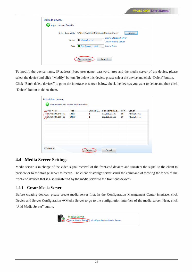
To modify the device name, IP address, Port, user name, password, area and the media server of the device, please
select the device and click ―Modify‖ button. To delete this device, please select the device and click ―Delete‖ button.
Click ―Batch delete devices‖ to go to the interface as shown below, check the devices you want to delete and then click
―Delete‖ button to delete them.
4.4 Media Server Settings
Media server is in charge of the video signal receival of the front-end devices and transfers the signal to the client to
preview or to the storage server to record. The client or storage server sends the command of viewing the video of the
front-end devices that is also transferred by the media server to the front-end devices.
4.4.1 Create Media Server
Before creating devices, please create media server first. In the Configuration Management Center interface, click
Device and Server Configuration Media Server to go to the configuration interface of the media server. Next, click
―Add Media Server‖ button.

NVMS-5000 User Manual
26
Please input the server name and password and then click ―OK‖ button.
4.4.2 Modify the Media Server of the Device
In the configuration interface of the media server, select the media server and the device of this media server and drag
the device to another media server. When the cursor becomes a green cross, release the mouse.
Please click ―OK‖ button to confirm the modification.
NVMS-5000 User Manual
27
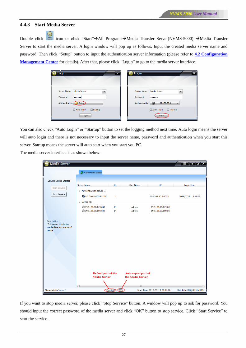
4.4.3 Start Media Server
Double click icon or click ―Start‖All ProgramsMedia Transfer Server(NVMS-5000) Media Transfer
Server to start the media server. A login window will pop up as follows. Input the created media server name and
password. Then click ―Setup‖ button to input the authentication server information (please refer to 4.2 Configuration
Management Center for details). After that, please click ―Login‖ to go to the media server interface.
You can also check ―Auto Login‖ or ―Startup‖ button to set the logging method next time. Auto login means the server
will auto login and there is not necessary to input the server name, password and authentication when you start this
server. Startup means the server will auto start when you start you PC.
The media server interface is as shown below:
If you want to stop media server, please click ―Stop Service‖ button. A window will pop up to ask for password. You
should input the correct password of the media server and click ―OK‖ button to stop service. Click ―Start Service‖ to
start the service.
NVMS-5000 User Manual
28
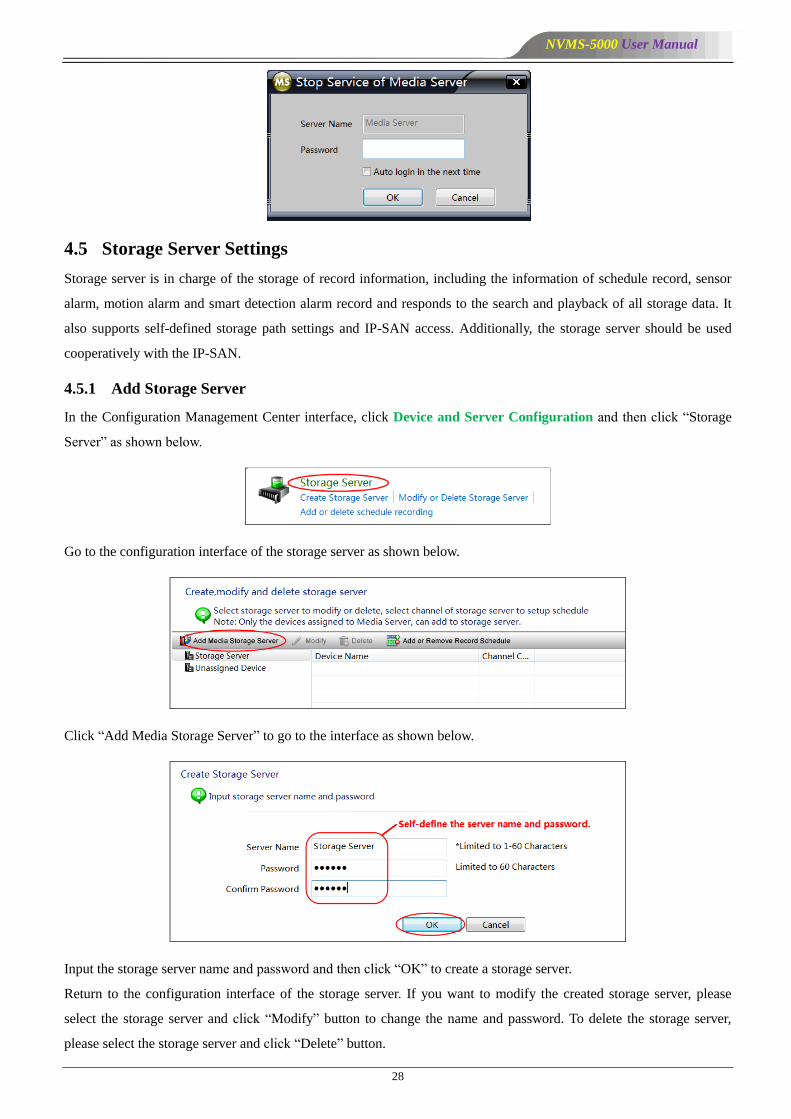
4.5 Storage Server Settings
Storage server is in charge of the storage of record information, including the information of schedule record, sensor
alarm, motion alarm and smart detection alarm record and responds to the search and playback of all storage data. It
also supports self-defined storage path settings and IP-SAN access. Additionally, the storage server should be used
cooperatively with the IP-SAN.
4.5.1 Add Storage Server
In the Configuration Management Center interface, click Device and Server Configuration and then click ―Storage
Server‖ as shown below.
Go to the configuration interface of the storage server as shown below.
Click ―Add Media Storage Server‖ to go to the interface as shown below.
Input the storage server name and password and then click ―OK‖ to create a storage server.
Return to the configuration interface of the storage server. If you want to modify the created storage server, please
select the storage server and click ―Modify‖ button to change the name and password. To delete the storage server,
please select the storage server and click ―Delete‖ button.

NVMS-5000 User Manual
29
4.5.2 Add Channels to Storage Server
In the configuration interface of the storage server, select a channel and drag the channel with the mouse into the
storage server. Release it when the cursor changes into a green cross. Then a dialog box will pop up to ask you whether
to move the channel. Please click ―OK‖ to confirm.
4.5.3 Setup Record Schedule
Return to the configuration interface of the storage server to set up record schedules for these channels. Click ―Add or
Remove Record Schedule‖.
Go to the record schedule setting interface as shown below, click storage server to view the device list. Select a
channel and click ―Add or Remove Record Schedule‖.
Go to the schedule setting interface as shown below, put the cursor on the schedule name to see the schedule. The
default schedule is ―7×24‖. You can check this schedule and then click ―OK‖ button to save the settings. You can also
click ―Create Schedule‖ button on the left menu bar to set other schedules (please refer to 4.7.1 Create Schedule for
detail information).

NVMS-5000 User Manual
30
4.5.4 IP-SAN Configuration
Start the IP-SAN, and then log in to the IE client of the IP-SAN to configure it. Input the default IP address
192.168.1.101 or 192.168.1.102 (connect the IP-SAN with a displayer to see it) in the IE address bar and then push
Enter key to go to the interface as shown below. Input the username and password of the IP-SAN and then click
―Login‖ button. The username is admin, and the password is admin.
You can view the basic information and disk RAID of the IP-SAN, set its date and time, network, username and
password, manage the server and upgrade the IP-SAN, etc.
Click ―Refresh‖ menu on the top right corner to refresh the client interface; click ―Logout‖ button menu to log out the
system; click ―Reboot‖ menu to reboot the IP-SAN; click ―Power Off‖ menu to power off the IP-SAN.
Basic Information
Click ―Basic Info‖ menu to view the product model and software version, etc.
NVMS-5000 User Manual
31
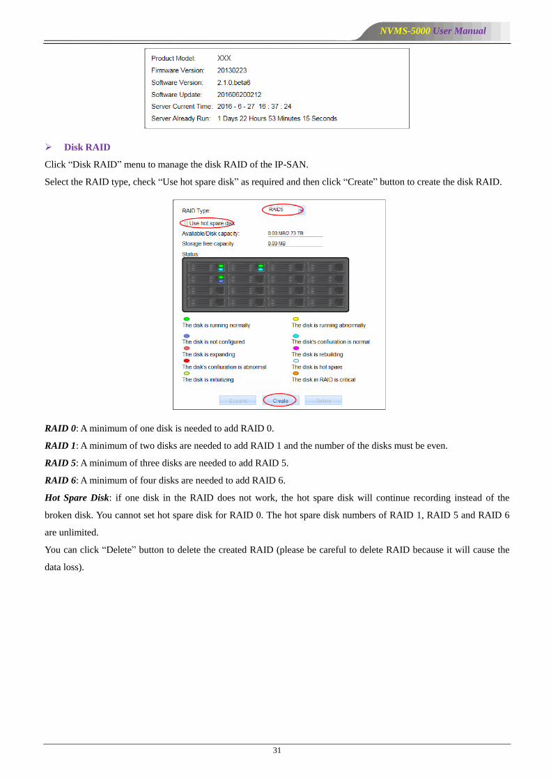
Disk RAID
Click ―Disk RAID‖ menu to manage the disk RAID of the IP-SAN.
Select the RAID type, check ―Use hot spare disk‖ as required and then click ―Create‖ button to create the disk RAID.
RAID 0: A minimum of one disk is needed to add RAID 0.
RAID 1: A minimum of two disks are needed to add RAID 1 and the number of the disks must be even.
RAID 5: A minimum of three disks are needed to add RAID 5.
RAID 6: A minimum of four disks are needed to add RAID 6.
Hot Spare Disk: if one disk in the RAID does not work, the hot spare disk will continue recording instead of the
broken disk. You cannot set hot spare disk for RAID 0. The hot spare disk numbers of RAID 1, RAID 5 and RAID 6
are unlimited.
You can click ―Delete‖ button to delete the created RAID (please be careful to delete RAID because it will cause the
data loss).

NVMS-5000 User Manual
32
If the disk room of the RAID is not enough for your requirement, you can expand your RAID.
Insert new disk to the IP-SAN, and then click ―Expand‖ button to expand the RAID.
Note: the capacity of the HDD inserted into the IP-SAN for expanding should not be lower than each HDD capacity of
the current RAID, or the expanding would fail. By RAID expanding you can increase the RAID capacity without
losing the record data.
Date & Time
Click ―Date & Time‖ menu to set the date and time of the IP-SAN.
Set the time zone, manually set the date and time, and then click ―Submit‖ to save the settings. Click ―Reset‖ to reset
system time.
Network
Click ―Network‖ menu to set the network of the IP-SAN.
Bonding IP: bind two network ports or above to one IP address. The advantages of using bonding IP: 1. increase the
bandwidth; 2. form a network redundant array to share the load. When a failure happens to one network port, the other
port will take over the entire load immediately. The takeover process is seamless and the network service will not be
broken off.
If the bonding IP is disabled, you should set the network addresses of eth0 and eth1 respectively. Refer to the below
left figure. Check ―Bind Static IP‖ of eth0 and eth1 and manually input the IP address, subnet mask and gateway. The
network addresses of eth0 and eth1 will be obtained automatically if you don’t check ―Bind Static IP‖. Input the
Preferred DNS Server and Alternate DNS Server address and then click ―Submit‖ button to save the settings.
Refer to the below right figure. If the bonding IP is enabled, you should set the network address and mode of the
bonding IP (the default mode is XOR policy).

NVMS-5000 User Manual
33
Note: The IP-SAN should be set to be in the same network segment with the Authentication Server if recording is
needed with the storage server.
Management Server
Click ―Management Server‖ menu to configure the management server and the local service of IP-SAN.
The four ports under the ―Local Service Config‖ can be self-defined.
The address and port of the management server should be the same with that of the Authentication Server (go to
Authentication Server to view the IP address and port).
The login name and login password of the management server should be the same with that of the Storage Server
created in the Configuration Management Center. Click ―Submit‖ button to save the settings.
You can click ―Stop‖ button to stop the service of the Authentication Server; click ―Startup‖ button to start the service
of the Authentication Server; click ―Restart‖ button to restart the Authentication Server.
NVMS-5000 User Manual
34
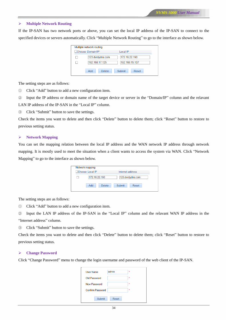
Multiple Network Routing
If the IP-SAN has two network ports or above, you can set the local IP address of the IP-SAN to connect to the
specified devices or servers automatically. Click ―Multiple Network Routing‖ to go to the interface as shown below.
The setting steps are as follows:
① Click ―Add‖ button to add a new configuration item.
② Input the IP address or domain name of the target device or server in the ―Domain/IP‖ column and the relavant
LAN IP address of the IP-SAN in the ―Local IP‖ column.
③ Click ―Submit‖ button to save the settings.
Check the items you want to delete and then click ―Delete‖ button to delete them; click ―Reset‖ button to restore to
previous setting status.
Network Mapping
You can set the mapping relation between the local IP address and the WAN network IP address through network
mapping. It is mostly used to meet the situation when a client wants to access the system via WAN. Click ―Network
Mapping‖ to go to the interface as shown below.
The setting steps are as follows:
① Click ―Add‖ button to add a new configuration item.
② Input the LAN IP address of the IP-SAN in the ―Local IP‖ column and the relavant WAN IP address in the
―Internet address‖ column.
③ Click ―Submit‖ button to save the settings.
Check the items you want to delete and then click ―Delete‖ button to delete them; click ―Reset‖ button to restore to
previous setting status.
Change Password
Click ―Change Password‖ menu to change the login username and password of the web client of the IP-SAN.
NVMS-5000 User Manual
35
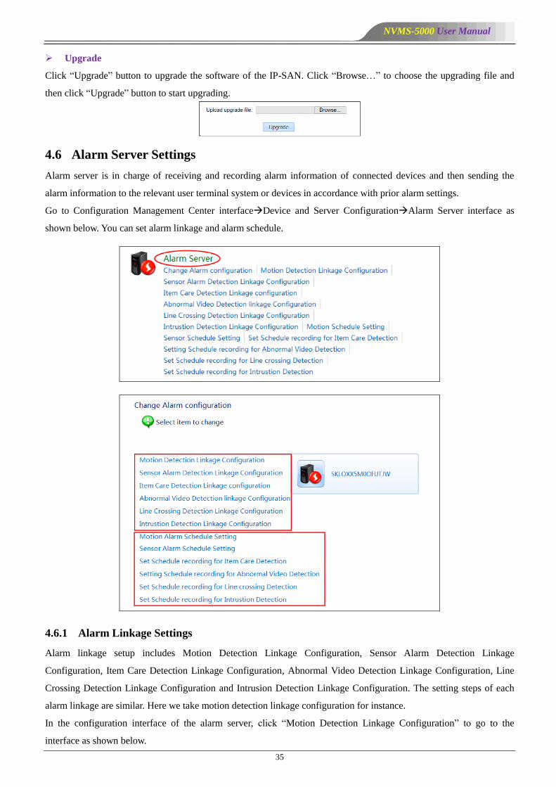
Upgrade
Click ―Upgrade‖ button to upgrade the software of the IP-SAN. Click ―Browse…‖ to choose the upgrading file and
then click ―Upgrade‖ button to start upgrading.
4.6 Alarm Server Settings
Alarm server is in charge of receiving and recording alarm information of connected devices and then sending the
alarm information to the relevant user terminal system or devices in accordance with prior alarm settings.
Go to Configuration Management Center interfaceDevice and Server ConfigurationAlarm Server interface as
shown below. You can set alarm linkage and alarm schedule.
4.6.1 Alarm Linkage Settings
Alarm linkage setup includes Motion Detection Linkage Configuration, Sensor Alarm Detection Linkage
Configuration, Item Care Detection Linkage Configuration, Abnormal Video Detection Linkage Configuration, Line
Crossing Detection Linkage Configuration and Intrusion Detection Linkage Configuration. The setting steps of each
alarm linkage are similar. Here we take motion detection linkage configuration for instance.
In the configuration interface of the alarm server, click ―Motion Detection Linkage Configuration‖ to go to the
interface as shown below.

NVMS-5000 User Manual
36
Select the device and then check ―Enable‖. The alarm linkage items are introduced as follows.
Trigger Recording: click under the title of Trigger Recording to pop up the ―Select the trigger record channel‖
window. Check the linkage record channels in the window and then click ―OK‖ to save the selected channel. Finally,
click ―Save‖ button in the motion detection linkage configuration interface to save all the settings.
Trigger Audio: Checkmark trigger audio and then click ―Save‖ button to save the settings.
Trigger Preview: click under the title of Trigger Preview to pop up the ―Choose the big screen channel‖ window.
Check the linkage preview channels in the window and then click ―OK‖ to save the selected channel. Finally, click
―Save‖ button in the motion detection linkage configuration interface to save all the settings.
NVMS-5000 User Manual
37
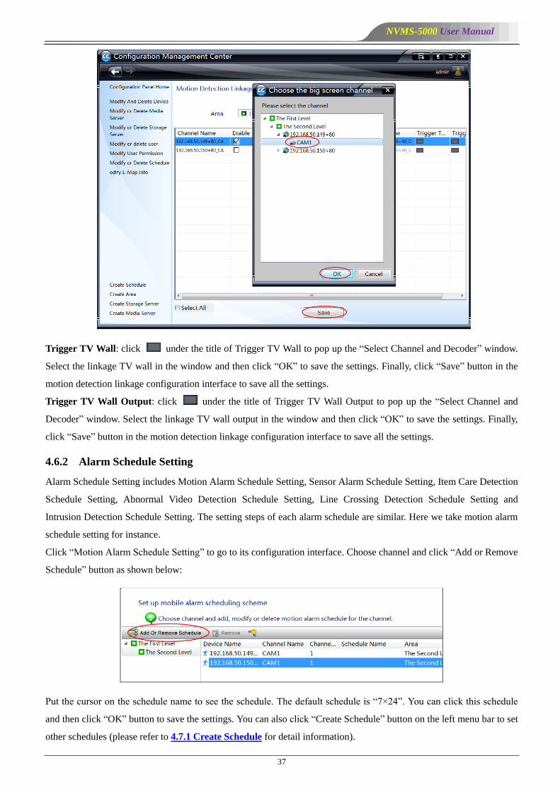
Trigger TV Wall: click under the title of Trigger TV Wall to pop up the ―Select Channel and Decoder‖ window.
Select the linkage TV wall in the window and then click ―OK‖ to save the settings. Finally, click ―Save‖ button in the
motion detection linkage configuration interface to save all the settings.
Trigger TV Wall Output: click under the title of Trigger TV Wall Output to pop up the ―Select Channel and
Decoder‖ window. Select the linkage TV wall output in the window and then click ―OK‖ to save the settings. Finally,
click ―Save‖ button in the motion detection linkage configuration interface to save all the settings.
4.6.2 Alarm Schedule Setting
Alarm Schedule Setting includes Motion Alarm Schedule Setting, Sensor Alarm Schedule Setting, Item Care Detection
Schedule Setting, Abnormal Video Detection Schedule Setting, Line Crossing Detection Schedule Setting and
Intrusion Detection Schedule Setting. The setting steps of each alarm schedule are similar. Here we take motion alarm
schedule setting for instance.
Click ―Motion Alarm Schedule Setting‖ to go to its configuration interface. Choose channel and click ―Add or Remove
Schedule‖ button as shown below:
Put the cursor on the schedule name to see the schedule. The default schedule is ―7×24‖. You can click this schedule
and then click ―OK‖ button to save the settings. You can also click ―Create Schedule‖ button on the left menu bar to set
other schedules (please refer to 4.7.1 Create Schedule for detail information).

NVMS-5000 User Manual
38
If you want to delete the set schedule, please choose the channel and then click ―Remove‖ button to delete it.
Note: If no alarm schedule is set up, the default schedule (7×24) will be used.
To conceal or reveal the device list of the child node, please click icon.
4.6.3 Alarm Status
Alarm Status: click ―Alarm Status‖ tab of the Authentication Server to see the alarm status of the devices.
NVMS-5000 User Manual
39
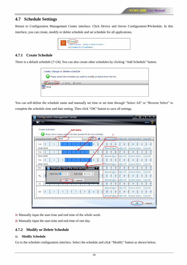
4.7 Schedule Settings
Return to Configuration Management Center interface. Click Device and Server ConfigurationSchedule. In this
interface, you can create, modify or delete schedule and set schedule for all applications.
4.7.1 Create Schedule
There is a default schedule (7×24). You can also create other schedules by clicking ―Add Schedule‖ button.
You can self-define the schedule name and manually set time or set time through ―Select All‖ or ―Reverse Select‖ to
complete the schedule time and date setting. Then click ―OK‖ button to save all settings.
1: Manually input the start time and end time of the whole week.
2: Manually input the start time and end time of one day.
4.7.2 Modify or Delete Schedule
1) Modify Schedule
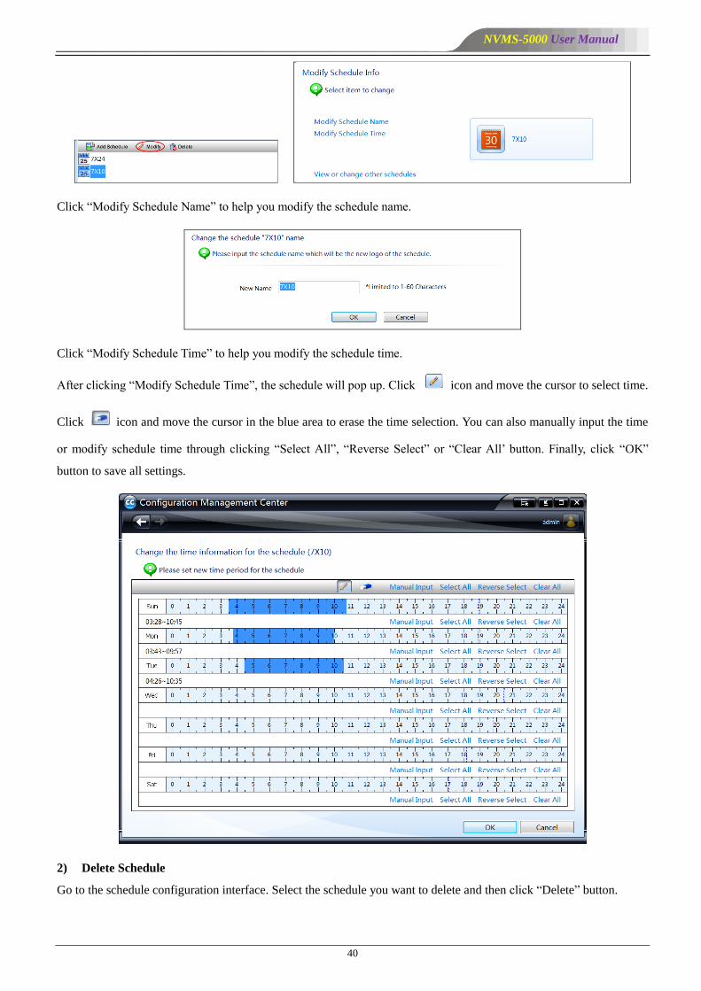
Go to the schedule configuration interface. Select the schedule and click ―Modify‖ button as shown below.
NVMS-5000 User Manual
40
Click ―Modify Schedule Name‖ to help you modify the schedule name.
Click ―Modify Schedule Time‖ to help you modify the schedule time.
After clicking ―Modify Schedule Time‖, the schedule will pop up. Click icon and move the cursor to select time.
Click icon and move the cursor in the blue area to erase the time selection. You can also manually input the time
or modify schedule time through clicking ―Select All‖, ―Reverse Select‖ or ―Clear All’ button. Finally, click ―OK‖
button to save all settings.
2) Delete Schedule
Go to the schedule configuration interface. Select the schedule you want to delete and then click ―Delete‖ button.
NVMS-5000 User Manual
41
4.7.3 Set Shedule for All Applications
Go to Device and Server Configuration interface. Click ―Set Schedule for All Applications‖ to set schedule recording,
motion schedule, sensor schedule, item care schedule, abnormal video schedule, line crossing schedule and intrusion
schedule.
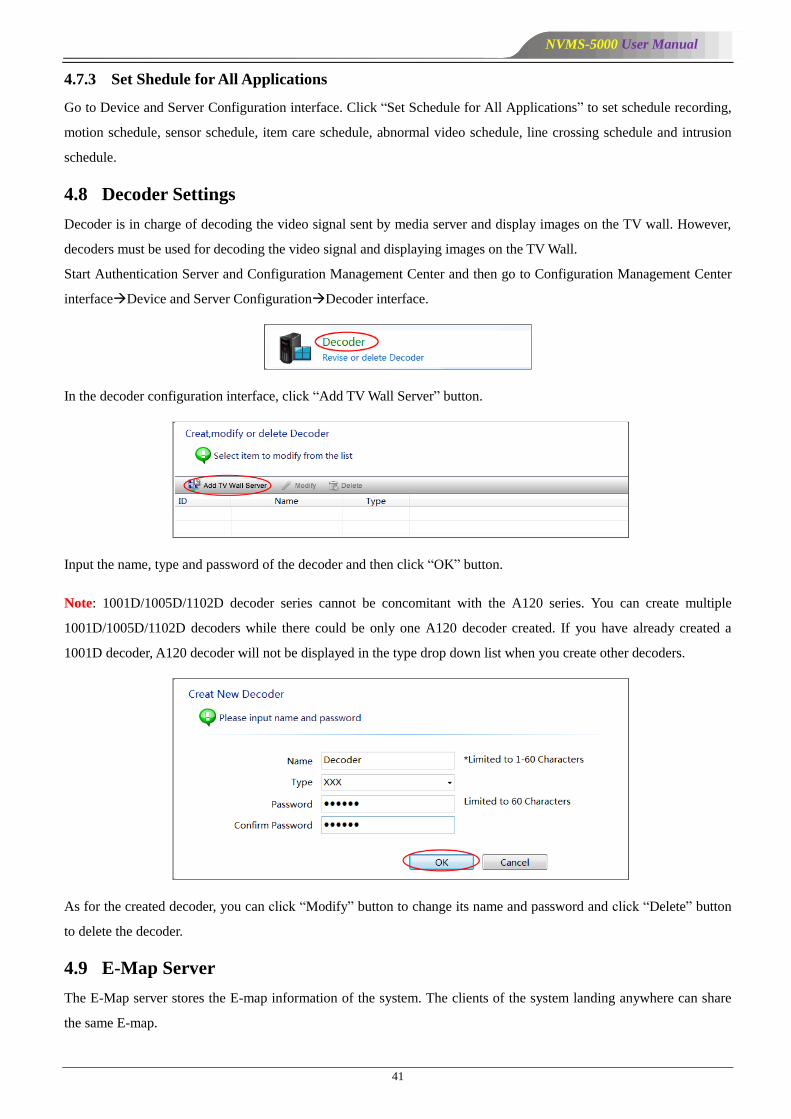
4.8 Decoder Settings
Decoder is in charge of decoding the video signal sent by media server and display images on the TV wall. However,
decoders must be used for decoding the video signal and displaying images on the TV Wall.
Start Authentication Server and Configuration Management Center and then go to Configuration Management Center
interfaceDevice and Server ConfigurationDecoder interface.
In the decoder configuration interface, click ―Add TV Wall Server‖ button.
Input the name, type and password of the decoder and then click ―OK‖ button.
Note: 1001D/1005D/1102D decoder series cannot be concomitant with the A120 series. You can create multiple
1001D/1005D/1102D decoders while there could be only one A120 decoder created. If you have already created a
1001D decoder, A120 decoder will not be displayed in the type drop down list when you create other decoders.
As for the created decoder, you can click ―Modify‖ button to change its name and password and click ―Delete‖ button
to delete the decoder.
4.9 E-Map Server
The E-Map server stores the E-map information of the system. The clients of the system landing anywhere can share
the same E-map.
NVMS-5000 User Manual
42
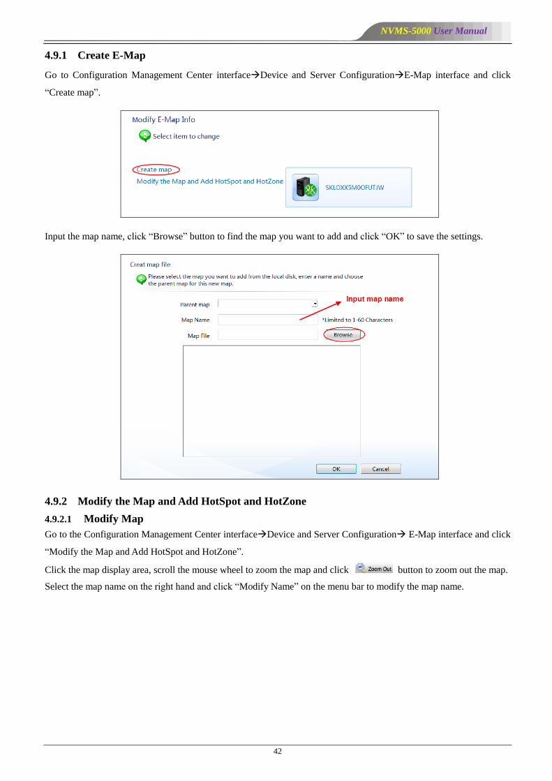
4.9.1 Create E-Map
Go to Configuration Management Center interfaceDevice and Server ConfigurationE-Map interface and click
―Create map‖.
Input the map name, click ―Browse‖ button to find the map you want to add and click ―OK‖ to save the settings.
4.9.2 Modify the Map and Add HotSpot and HotZone
4.9.2.1 Modify Map
Go to the Configuration Management Center interfaceDevice and Server Configuration E-Map interface and click
―Modify the Map and Add HotSpot and HotZone‖.
Click the map display area, scroll the mouse wheel to zoom the map and click button to zoom out the map.
Select the map name on the right hand and click ―Modify Name‖ on the menu bar to modify the map name.
NVMS-5000 User Manual
43
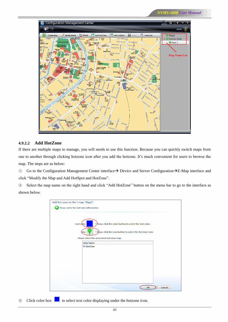
4.9.2.2 Add HotZone
If there are multiple maps to manage, you will needs to use this function. Because you can quickly switch maps from
one to another through clicking hotzone icon after you add the hotzone. It’s much convenient for users to browse the
map. The steps are as below:
① Go to the Configuration Management Center interface Device and Server ConfigurationE-Map interface and
click ―Modify the Map and Add HotSpot and HotZone‖.
② Select the map name on the right hand and click ―Add HotZone‖ button on the menu bar to go to the interface as
shown below.
③ Click color box to select text color displaying under the hotzone icon.

NVMS-5000 User Manual
44
④ Click icon to choose the hotzone icon displaying on the map.
⑤ Check the associated map.
⑥ Click ―OK‖ button to save the settings.
The hotzone icon can be moved anywhere. To switch to the designated map, click this icon. If you delete or modify
this hot zone, you can right click and select ―Delete‖ or ―Modify the properties‖.
⑦ Adjust the position of this hotzone icon and then click ―Save‖ button to save the hotzone.
4.9.2.3 Add HotSpot
The position of the monitor can be displayed on the map by adding hotspots so that the position of cameras and alarms
can be vividly shown. The setting steps are as follows:
① Select the map on the right hand and click ―Add HotSpot‖ button on the menu bar.
② Select the text color of the hotspot.
③ Click icon to select the hotspot icon.
④ Input the hotspot name and select the associated camera.
⑤ Click ―OK‖ button to save the settings.
You can drag the hotspot icon anywhere. Please move it to the right position on the map according to the actual
position of the camera.
Right click the hotspot to delete or modify the hotspot.
⑥ Adjust the position of the hotspot and then click ―Save‖ button on the menu bar.
4.10 User and Permission
NVMS-5000 user consists of operator and administrator. The permission of administrator cannot be modified. Only the
permission of the operator can be set.

NVMS-5000 User Manual
45
4.10.1 Add User
Go to Configuration Management CenterUser and PermissionUser Account interface and click ―Add User‖
button.
Input username, password and select user type and area. Then click ―OK‖ to add a user.
4.10.2 Modify User Permission
If the added user is an operator user, you can modify the permission. Select this user and click ―Modify User
Permission‖ button as shown below:
The permission includes device permission, channel permission, TV Wall permission and EMap permission.

NVMS-5000 User Manual
46
Click ―Add Resource‖ button to pop up a dialog box. Select the area, device or channel you want to add. Finally, click
―OK‖ to add a new permission list.
Drag the scroll bar down to set TV Wall permission and EMap permission.
You just need to check the relevant decoders and then click ―OK‖ to save the setting. You must add decoders first
before TV wall permission setting.
Drag the scroll bar down to set EMap permission. You must add maps first before EMap permission setting. Check the
relevant maps and click ―OK‖ to save the setting.
NVMS-5000 User Manual
47
Additionally, you can also click ―Modify‖ button to change user’s permission, name, and password and so on. You can
click ―Delete‖ button to delete the created users.
Note: The permission of administrator cannot be modified. If you close the permission control for the specified user,
then the user will have the same permissions as the administrator.
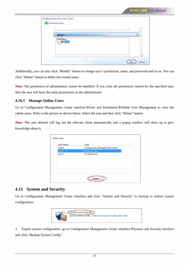
4.10.3 Manage Online Users
Go to Configuration Management Center interfaceUser and PermissionOnline User Management to view the
online users. Refer to the picture as shown below. Select the user and then click ―Delete‖ button.
Note: The user deleted will log out the relevant client automatically and a popup window will show up to give
knowledge about it.
4.11 System and Security
Go to Configuration Management Center interface and click ―System and Security‖ to backup or restore system
configuration.
Export system configuration: go to Configuration Management Center interfaceSystem and Security interface
and click ―Backup System Config‖.

NVMS-5000 User Manual
48
Click ―Browse‖ to set the export path and the file name and then click ―OK‖ button.
Import system configuration: go to Configuration Management Center interfaceSystem and Security interface
and click ―Restore the system configuration data‖.
Click ―Browse‖ to select the configuration file you need to import and then click ―OK‖ button.

NVMS-5000 User Manual
49
5.1 Monitor Client
Monitor client is in charge of real-time preview, playback, PTZ control, alarm preview and so on. Only when the
authentication server, media server and storage server is started, can you start monitor client to view real-time video,
record and alarm information.
5.1.1 Start Monitor Client
Before starting monitor client, you must start authentication server and media server first; create and configure the
storage server as well as IP-SAN before recording and playback.
Double click or click ―Start‖All ProgramsClient (NVMS-5000)Client to pop up a login window as
shown below. Please input the user name and password created in 4.10.1 Add User. Then click ―Setup‖ button to input
the information about authentication server (please refer to 4.2 Configuration Management Center for detail
information). Finally, select Monitor Client in the ―Client Type‖ and then click ―Login‖ button to go to the Monitor
Client interface.
Note:One user can only login to one client. For example, user1 who has already logged in to Configuration
Management Center cannot login to Monitor Client at the same time. If user1 wants to login to Monitor Client, he
needs to exit Configuration Management Center first and then log into Monitor Client.
After logging in to the monitor client, the following interface shows.
5 NVMS-5000 Client
NVMS-5000 User Manual
50
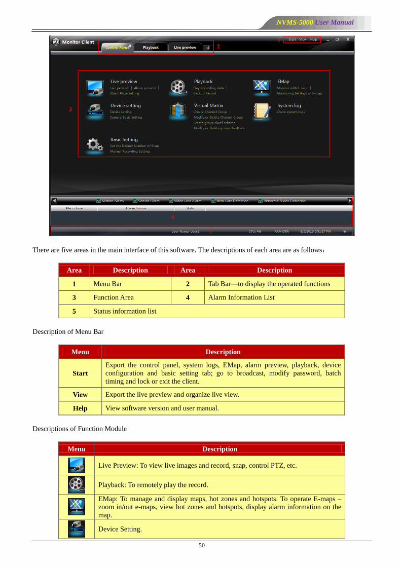
There are five areas in the main interface of this software. The descriptions of each area are as follows:
Area Description Area Description
1 Menu Bar 2 Tab Bar—to display the operated functions
3 Function Area 4 Alarm Information List
5 Status information list
Description of Menu Bar
Menu Description
Start
Export the control panel, system logs, EMap, alarm preview, playback, device
configuration and basic setting tab; go to broadcast, modify password, batch
timing and lock or exit the client.
View Export the live preview and organize live view.
Help View software version and user manual.
Descriptions of Function Module
Menu Description
Live Preview: To view live images and record, snap, control PTZ, etc.
Playback: To remotely play the record.
EMap: To manage and display maps, hot zones and hotspots. To operate E-maps –
zoom in/out e-maps, view hot zones and hotspots, display alarm information on the
map.
Device Setting.

NVMS-5000 User Manual
51
Menu Description
Virtual Matrix: To create, modify or delete camera groups and schemes.
System Log: To search, view and backup system log.
Basic Setting: To setup record path, system startup and maintenance.
Descriptions of Other Buttons
Button Description
Click it to hide the window
Click it to zoom in/out the window
Click it to exit the window
Click it to extend or shrink the window (eg. Extend or shrink the list of alarm
information list)
5.1.2 Group and Scheme Setting
In monitor client control panel interface, click ―Virtual Matrix‖ to go to the following interface.
5.1.2.1 Channel Group Setting
Click ―Create Channel Group‖ to create a channel group.
NVMS-5000 User Manual
52
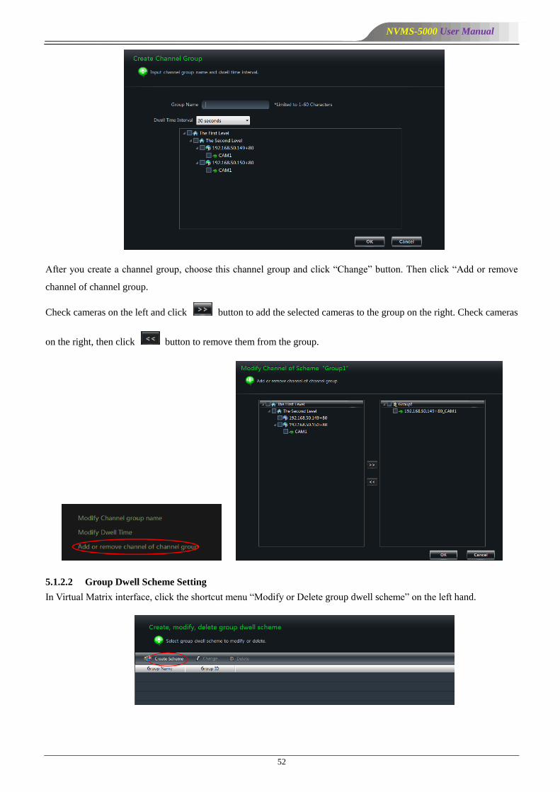
After you create a channel group, choose this channel group and click ―Change‖ button. Then click ―Add or remove
channel of channel group.
Check cameras on the left and click button to add the selected cameras to the group on the right. Check cameras
on the right, then click button to remove them from the group.
5.1.2.2 Group Dwell Scheme Setting
In Virtual Matrix interface, click the shortcut menu ―Modify or Delete group dwell scheme‖ on the left hand.
NVMS-5000 User Manual
53
Click ―Create Scheme‖ to create a group dwell scheme. Then select this scheme and click ―Change‖ button; choose
―Add or remove channel group of group dwell scheme‖. The way to add or remove channel group of group dwell
scheme is the same as the channel group setting. Please see the above-mentioned setting.
5.1.3 Live and Alarm Preview
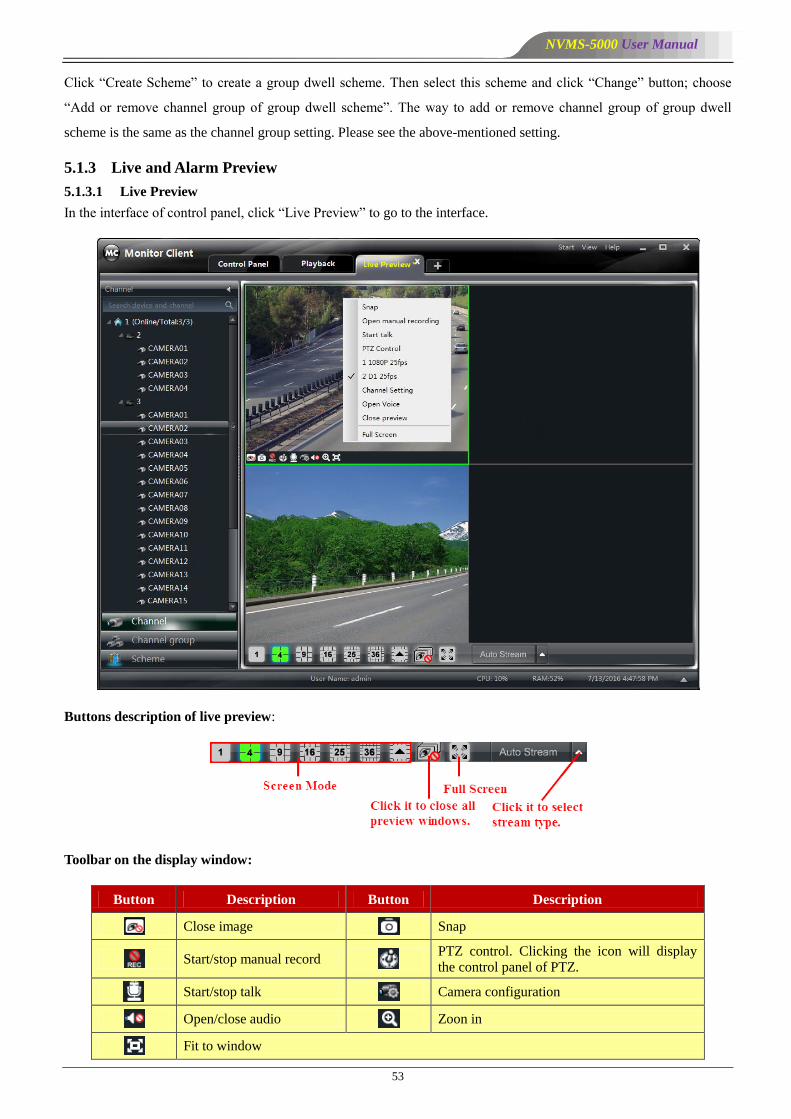
5.1.3.1 Live Preview
In the interface of control panel, click ―Live Preview‖ to go to the interface.
Buttons description of live preview:
Toolbar on the display window:
Button Description Button Description
Close image Snap
Start/stop manual record PTZ control. Clicking the icon will display
the control panel of PTZ.
Start/stop talk Camera configuration
Open/close audio Zoon in
Fit to window

NVMS-5000 User Manual
54
Right button functions:
Menu Description Menu Description
Snap Snap picture Open Manual
Recording Start manual recording
Start talk Start or stop talk Stream Choose stream to view.
Channel
Setting
Click it to go to the interface of the
area and Camera configuration PTZ Control
To display the control panel of
PTZ
Open Voice Open or close audio Close Preview Close single channel preview
Full Screen To display in full screen
Note:Click icon to turn off all channels,but click icon to turn off the single channel.
Monitory Point Preview
To start the live preview, drag the cameras from the list to the right display window or select a window and
double-click the camera to display the live image.
You can drag the image to any window at random.
Note: Node unfold rule: After the first time for setting the device and area, you shall obey the following rule to view
all tree nodes: the first-level nodes will be unfolded by default to show the devices and the second-level nodes; the
second-level nodes will not be unfolded.
For example: A (There is camera group AC under A; sub-area a under AC; camera group ac under sub-area a). A will
be unfolded and AC will be displayed, but a will not be unfolded and ac will not be displayed. You should unfold ac
manually.
Stop Preview
Close Preview of Channel
Place your mouse on the window to display the menu
toolbar, then click icon to close preview of this
channel.
Close Preview by Right-clicking
Choose Close Preview by right-clicking the display
window to close preview of this channel.
Close All Preview
Click icon on the main menu toolbar to close all the
windows.
Group Dwell Preview
Click ―Channel Group‖ button on the lower left corner.
Choose a window and then double click the group to view the group dwell image.

NVMS-5000 User Manual
55
Group Dwell Scheme Preview
Click ―Scheme‖ button on the lower left corner.
Choose a window and then double click the scheme to view the group dwell scheme. The system will display the
screen mode automatically.
Stop Channel Group or Group Dwell Scheme
Click icon to close all the windows for stopping channel group or group dwell scheme.
Preview Control
Full Screen
Click icon in the live preview interface or right-click
the preview window to choose ―Full Screen‖ to view in
full screen.
Right-click to choose ―Exit Full Screen‖ to exit full screen
preview.
Single Channel in Full Screen
Double click the selected window to view in full screen.
Double click again to recover the window.
Stream of Live Preview
Right click on the display window to choose recording
stream as shown on the right. The above stream is
mainstream (eg: 1080P 25fps) and the below is sub stream
(eg: D1 25fps).
Modify Device Stream: Click button on the preview
window to go to the Area and Camera Management
interface. Click ―Image Quality‖ under Image Setting to
modify device stream.
NVMS-5000 User Manual
56
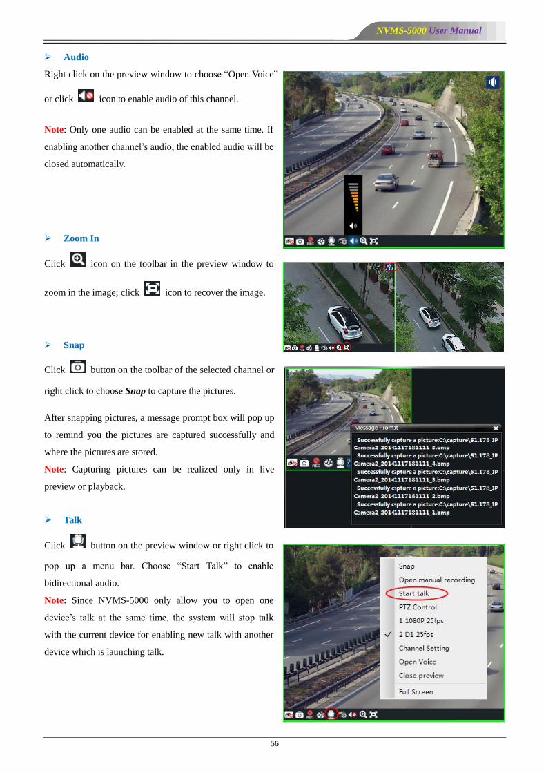
Audio
Right click on the preview window to choose ―Open Voice‖
or click icon to enable audio of this channel.
Note: Only one audio can be enabled at the same time. If
enabling another channel’s audio, the enabled audio will be
closed automatically.
Zoom In
Click icon on the toolbar in the preview window to
zoom in the image; click icon to recover the image.
Snap
Click button on the toolbar of the selected channel or
right click to choose Snap to capture the pictures.
After snapping pictures, a message prompt box will pop up
to remind you the pictures are captured successfully and
where the pictures are stored.
Note: Capturing pictures can be realized only in live
preview or playback.
Talk
Click button on the preview window or right click to
pop up a menu bar. Choose ―Start Talk‖ to enable
bidirectional audio.
Note: Since NVMS-5000 only allow you to open one
device’s talk at the same time, the system will stop talk
with the current device for enabling new talk with another
device which is launching talk.
NVMS-5000 User Manual
57
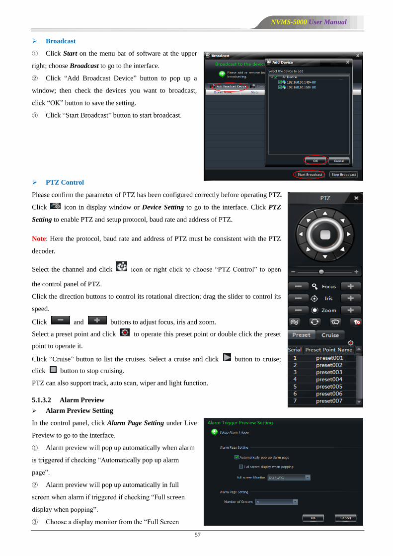
Broadcast
① Click Start on the menu bar of software at the upper
right; choose Broadcast to go to the interface.
② Click ―Add Broadcast Device‖ button to pop up a
window; then check the devices you want to broadcast,
click ―OK‖ button to save the setting.
③ Click ―Start Broadcast‖ button to start broadcast.
PTZ Control
Please confirm the parameter of PTZ has been configured correctly before operating PTZ.
Click icon in display window or Device Setting to go to the interface. Click PTZ
Setting to enable PTZ and setup protocol, baud rate and address of PTZ.
Note: Here the protocol, baud rate and address of PTZ must be consistent with the PTZ
decoder.
Select the channel and click icon or right click to choose ―PTZ Control‖ to open
the control panel of PTZ.
Click the direction buttons to control its rotational direction; drag the slider to control its
speed.
Click and buttons to adjust focus, iris and zoom.
Select a preset point and click to operate this preset point or double click the preset
point to operate it.
Click ―Cruise‖ button to list the cruises. Select a cruise and click button to cruise;
click button to stop cruising.
PTZ can also support track, auto scan, wiper and light function.
5.1.3.2 Alarm Preview
Alarm Preview Setting
In the control panel, click Alarm Page Setting under Live
Preview to go to the interface.
① Alarm preview will pop up automatically when alarm
is triggered if checking ―Automatically pop up alarm
page‖.
② Alarm preview will pop up automatically in full
screen when alarm if triggered if checking ―Full screen
display when popping‖.
③ Choose a display monitor from the ―Full Screen

NVMS-5000 User Manual
58
Monitor‖ drop-down menu. The alarm image will display on the designated monitor when alarm is triggered.
④ Choose the number of screen.
Alarm Preview
In the Configuration Management Center, set up alarm linkage and alarm schedule for alarm server. The monitor client
will pop up the relevant image on an alarm. In the monitor client, click ―Alarm Preview‖ to go to the following
interface.
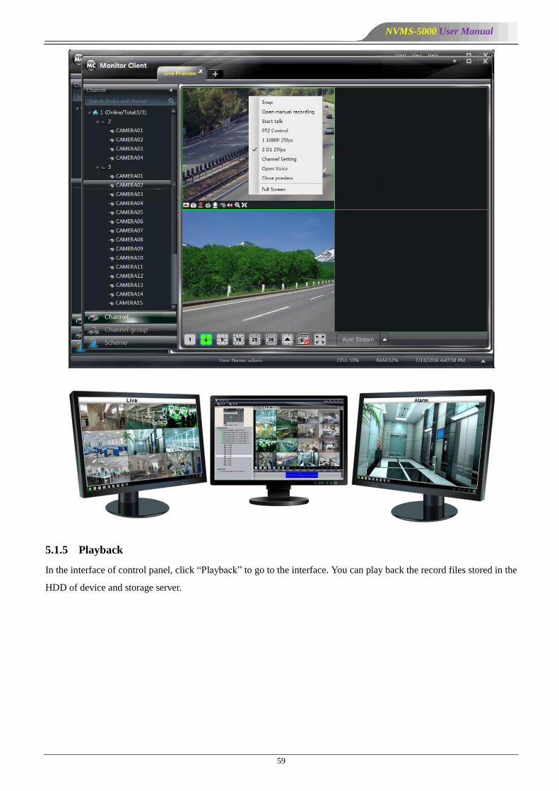
5.1.4 Multi-screen Display
In the interface of live preview, click button to plus a tab of live preview. Drag any tab of live preview or right
click the tab of live preview to select ―Float‖ to pop up an independent live preview interface as shown below.
Multi-screen to display can be realized by dragging the independent interface to other screen (graphics card should
support multi-screen output at the same time).
NVMS-5000 User Manual
59
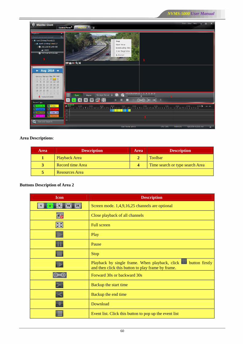
5.1.5 Playback
In the interface of control panel, click ―Playback‖ to go to the interface. You can play back the record files stored in the
HDD of device and storage server.
NVMS-5000 User Manual
60
Area Descriptions:
Area Description Area Description
1 Playback Area 2 Toolbar
3 Record time Area 4 Time search or type search Area
5 Resources Area
Buttons Description of Area 2
Icon Description
Screen mode. 1,4,9,16,25 channels are optional
Close playback of all channels
Full screen
Play
Pause
Stop
Playback by single frame. When playback, click button firstly
and then click this button to play frame by frame.
Forward 30s or backward 30s
Backup the start time
Backup the end time
Download
Event list. Click this button to pop up the event list
NVMS-5000 User Manual
61
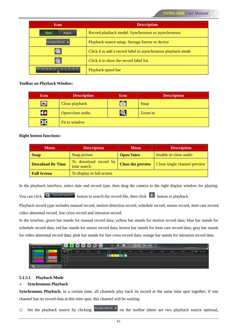
Icon Description
Record playback model. Synchronous or asynchronous
Playback source setup. Storage Server or device
Click it to add a record label in asynchronous playback mode
Click it to show the record label list
Playback speed bar
Toolbar on Playback Window:
Icon Description Icon Description
Close playback Snap
Open/close audio Zoom in
Fit to window
Right button functions:
Menu Description Menu Description
Snap Snap picture Open Voice Enable or close audio
Download By Time To download record by
time search Close the preview Close single channel preview
Full Screen To display in full screen
In the playback interface, select date and record type, then drag the camera to the right display window for playing.
You can click button to search the record file, then click button to playback.
Playback record type includes manual record, motion detection record, schedule record, sensor record, item care record,
video abnormal record, line cross record and intrusion record.
In the timeline, green bar stands for manual record data; yellow bar stands for motion record data; blue bar stands for
schedule record data; red bar stands for sensor record data; brown bar stands for item care record data; gray bar stands
for video abnormal record data; pink bar stands for line cross record data; orange bar stands for intrusion record data.
5.1.5.1 Playback Mode
Synchronous Playback
Synchronous Playback: in a certain time, all channels play back its record at the same time spot together; if one
channel has no record data at this time spot, this channel will be waiting.
① Set the playback source by clicking on the toolbar (there are two playback source optional,
NVMS-5000 User Manual
62
storage server and device; if device is selected, the default playback mode is synchronous playback; if storage server is
selected, the default playback mode is asynchronous playback).
② Click to switch to synchronous playback mode.
③ Select the playback date and record type on the left side of the playback interface.
④ Start to play back the record synchronously by one of these three ways mentioned as follows:
Drag the channel to the playback window directly.
Select one playback window and then double click one channel to play back the channel record in the
selected window.
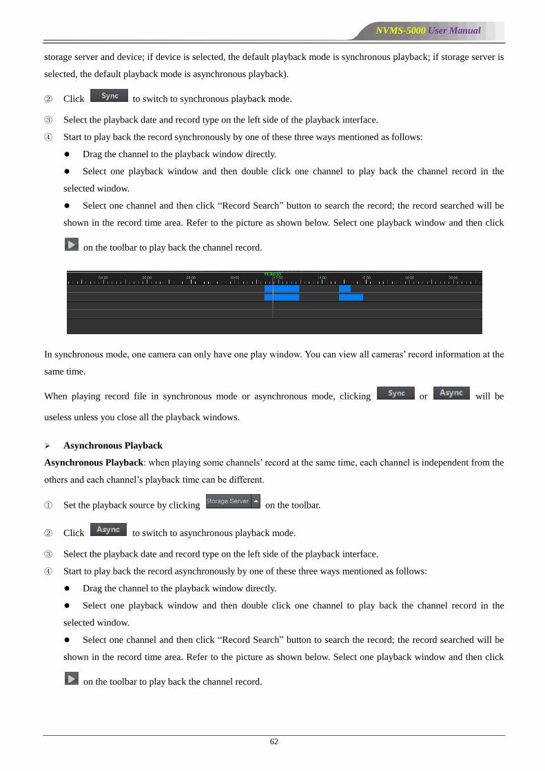
Select one channel and then click ―Record Search‖ button to search the record; the record searched will be
shown in the record time area. Refer to the picture as shown below. Select one playback window and then click
on the toolbar to play back the channel record.
In synchronous mode, one camera can only have one play window. You can view all cameras’ record information at the
same time.
When playing record file in synchronous mode or asynchronous mode, clicking or will be
useless unless you close all the playback windows.
Asynchronous Playback
Asynchronous Playback: when playing some channels’ record at the same time, each channel is independent from the
others and each channel’s playback time can be different.
① Set the playback source by clicking on the toolbar.
② Click to switch to asynchronous playback mode.
③ Select the playback date and record type on the left side of the playback interface.
④ Start to play back the record asynchronously by one of these three ways mentioned as follows:
Drag the channel to the playback window directly.
Select one playback window and then double click one channel to play back the channel record in the
selected window.
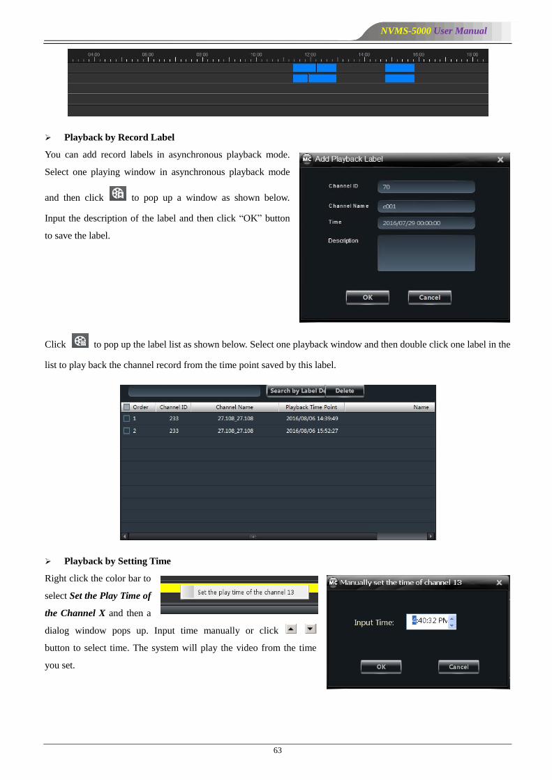
Select one channel and then click ―Record Search‖ button to search the record; the record searched will be
shown in the record time area. Refer to the picture as shown below. Select one playback window and then click
on the toolbar to play back the channel record.
NVMS-5000 User Manual
63
Playback by Record Label
You can add record labels in asynchronous playback mode.
Select one playing window in asynchronous playback mode
and then click to pop up a window as shown below.
Input the description of the label and then click ―OK‖ button
to save the label.
Click to pop up the label list as shown below. Select one playback window and then double click one label in the
list to play back the channel record from the time point saved by this label.
Playback by Setting Time
Right click the color bar to
select Set the Play Time of
the Channel X and then a
dialog window pops up. Input time manually or click
button to select time. The system will play the video from the time
you set.
NVMS-5000 User Manual
64
Playback by Searching Event
Click button to display the event list. Double click an event to play this event record.
Note: and buttons on the timeline are used to expand and narrow down the time bar, so you can choose a
more accurate playback time.
What’s more, you may also change playback speed by dragging bar.
5.1.5.2 Take Snapshot When Playback
Click button on the playing window to capture pictures. A message prompt will pop up after snapping.
5.1.5.3 Clip and Backup Record
When playing back record file, click button to set the start time; click button to set the end time. Then
click button to download the video files within the configured time.
Note: The default path is C:\\backup.
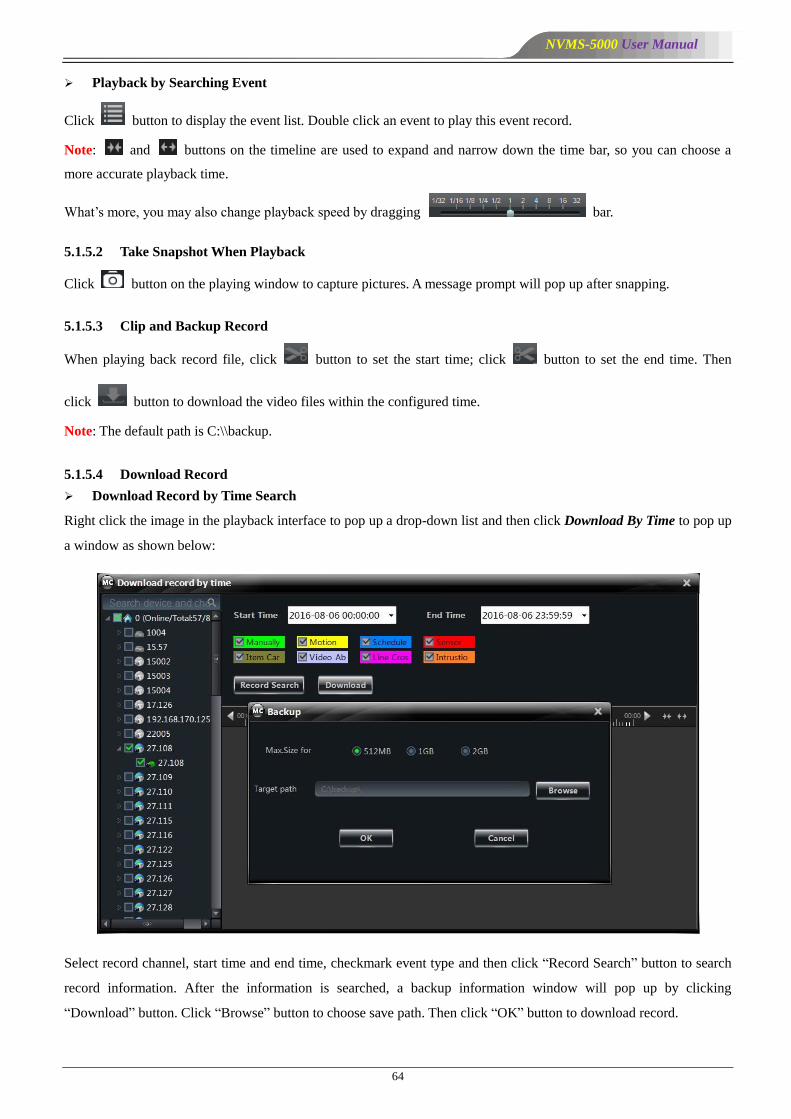
5.1.5.4 Download Record
Download Record by Time Search
Right click the image in the playback interface to pop up a drop-down list and then click Download By Time to pop up
a window as shown below:
Select record channel, start time and end time, checkmark event type and then click ―Record Search‖ button to search
record information. After the information is searched, a backup information window will pop up by clicking
―Download‖ button. Click ―Browse‖ button to choose save path. Then click ―OK‖ button to download record.
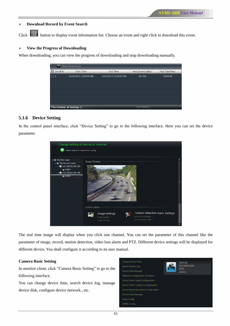
NVMS-5000 User Manual
65
Download Record by Event Search
Click button to display event information list. Choose an event and right click to download this event.
View the Progress of Downloading
When downloading, you can view the progress of downloading and stop downloading manually.
5.1.6 Device Setting
In the control panel interface, click ―Device Setting‖ to go to the following interface. Here you can set the device
parameter.
The real time image will display when you click one channel. You can set the parameter of this channel like the
parameter of image, record, motion detection, video loss alarm and PTZ. Different device settings will be displayed for
different device. You shall configure it according to its user manual.
Camera Basic Setting
In monitor client, click ―Camera Basic Setting‖ to go to the
following interface.
You can change device time, search device log, manage
device disk, configure device network., etc.
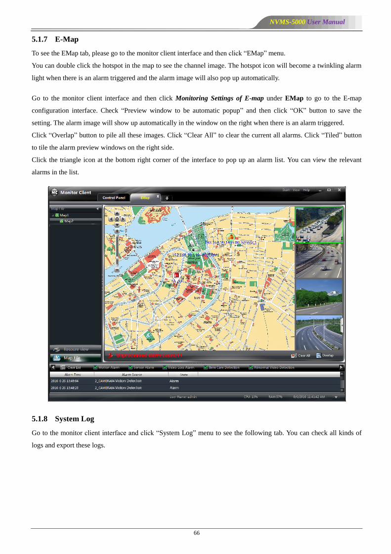
NVMS-5000 User Manual
66
5.1.7 E-Map
To see the EMap tab, please go to the monitor client interface and then click ―EMap‖ menu.
You can double click the hotspot in the map to see the channel image. The hotspot icon will become a twinkling alarm
light when there is an alarm triggered and the alarm image will also pop up automatically.
Go to the monitor client interface and then click Monitoring Settings of E-map under EMap to go to the E-map
configuration interface. Check ―Preview window to be automatic popup‖ and then click ―OK‖ button to save the
setting. The alarm image will show up automatically in the window on the right when there is an alarm triggered.
Click ―Overlap‖ button to pile all these images. Click ―Clear All‖ to clear the current all alarms. Click ―Tiled‖ button
to tile the alarm preview windows on the right side.
Click the triangle icon at the bottom right corner of the interface to pop up an alarm list. You can view the relevant
alarms in the list.
5.1.8 System Log
Go to the monitor client interface and click ―System Log‖ menu to see the following tab. You can check all kinds of
logs and export these logs.

NVMS-5000 User Manual
67
Select the main type and sub type, start time and end time and then click ―Search‖ button to see the relevant log
information.
If you need to export the log information, you can click ―Export‖ button after you search the relevant log information
and then select the export path. Finally, click ―Save‖ button to export those logs to the designated folder.
5.1.9 Basic Setting
Click ―Basic Setting‖ in the monitor client to go to the following interface.
In this interface, you can set record path, record backup path, snap path and the default number of the snap as well as
system startup and maintenance.
5.1.9.1 Video Path Setting
Click ―Set the Record Path‖ to go to the interface and then click ―Browse‖ to set the path; finally, click ―OK‖ to save
the setting. Click other shortcut menus to go to each interface and choose the path separately.

NVMS-5000 User Manual
68
5.1.9.2 System Startup and Maintenance
In the interface of Basic Setting, click System Startup and
Maintenance to go to the interface.
Under ―Set the Automatic Startup and Login‖, two ways to
enable the software can be selected.
If checking ―Auto Reboot PC‖ , user name and password
of the computer need to be input; time interval and restart
time need to be selected.
5.2 Web Client
5.2.1 Operating Environment of Web Client
The web client supports IE9/IE10/IE11, Firefox or Google browser. Please make sure that your browser supports the
downloading and use of the Web Client.
Checkup whether the IE browser prohibits Active X control from downloading:
Open IE browser, click Internet OptionsSecurityCustom level… to pop up a security settings window.
Then enable all sub options under ―Active X controls and plug-ins‖.
Checkup whether there are other components or antivirus to stop downloading Active X control. Please close
other components and configure antivirus and firewall to allow the installation of the files named NetLiveMonitor.exe
and NetPlayback.exe.
5.2.2 Start IE Client
Before starting IE client, Authentication Server and Media Server must be started first. Then Open Apache. You can
check it from the lower right corner of the PC as shown below.
Login
Input the IP address or domain name of Authentication Server and the web server port, for example:
http://192.168.50.3:8088 (In this example, IP address is 192.168.50.3. The default web server port is 8088) to go to IE
Client. Then input the user name and password you created in Account and Permission interface, select the language
and input the verify code; click ―Login‖ to login to the IE client.

NVMS-5000 User Manual
69
Please download the relavant Active X controls according to the tips if you login to the IE client for the first time.
The live interface is as shown below.
Click Playback tab to see the playback interface.
Select the playback window and playback date and then click button beside the camera name. This will take you to
see the image.
The operation steps of this IE monitoring interface are similar to that of the monitor client. Please refer to relevant
chapter for details.

NVMS-5000 User Manual
70
5.3 TV Wall Client
5.3.1 Start TV Wall Client
Authentication Server and Media Server must be started first. Please make sure images can be normally displayed on
the TV Wall Screen. Double click icon or click ―Start‖All ProgramsClient (NVMS-5000)Client to pop
up a login window as shown below. Input the username and password created in the Configuration Management Center.
Then click ―Setup‖ button to input the relevant information of authentication server (please refer to 4.2 Configuration
Management Center for more details). Finally, select TV Wall Client in the ―Client Type‖ and then click ―Login‖
button to go to the TV Wall Client interface.
The main interface of TV Wall Client displays as follows. ―Resource browse‖ includes all front-end video devices and
their channels. ―Channel group‖ includes all defined channel dwell scheme; ―Output‖ includes all decoding outputs.
Note: The quantity of the video decoding outputs is determined by the type of the decoder. TD-1001D supports 4
outputs, TD-1005D supports 5 outputs, TD-1102D supports 2 outputs.
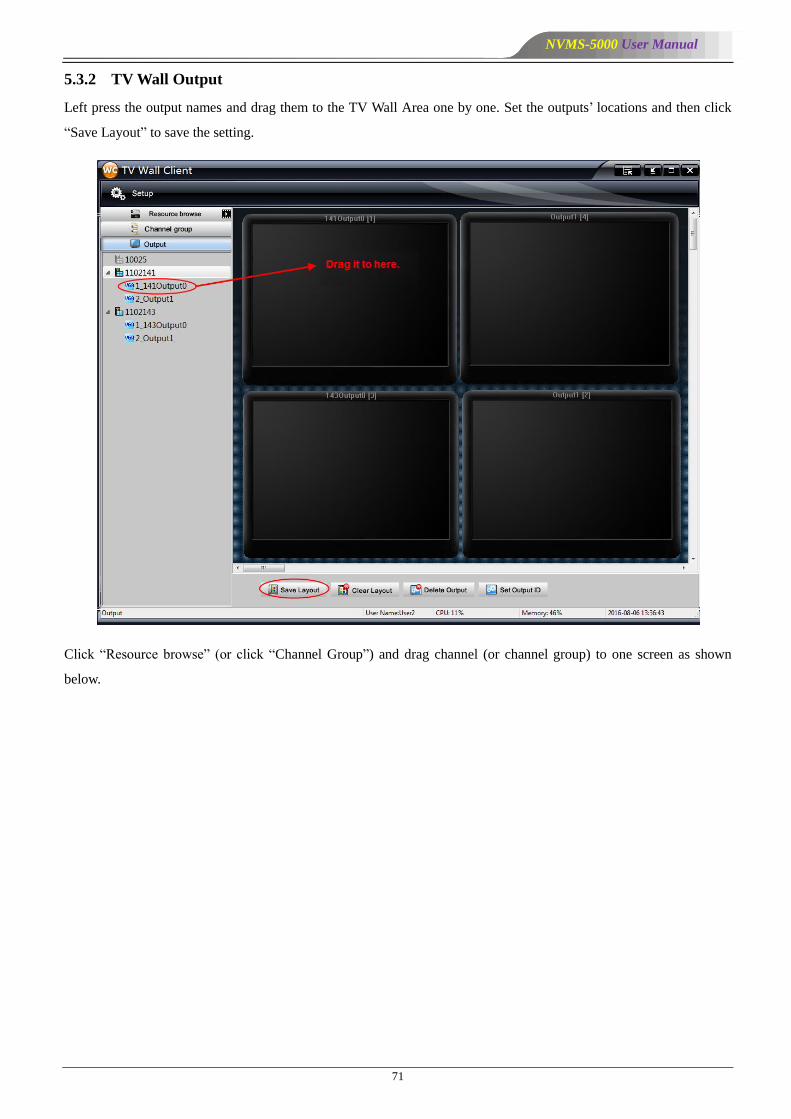
NVMS-5000 User Manual
71
5.3.2 TV Wall Output
Left press the output names and drag them to the TV Wall Area one by one. Set the outputs’ locations and then click
―Save Layout‖ to save the setting.
Click ―Resource browse‖ (or click ―Channel Group‖) and drag channel (or channel group) to one screen as shown
below.
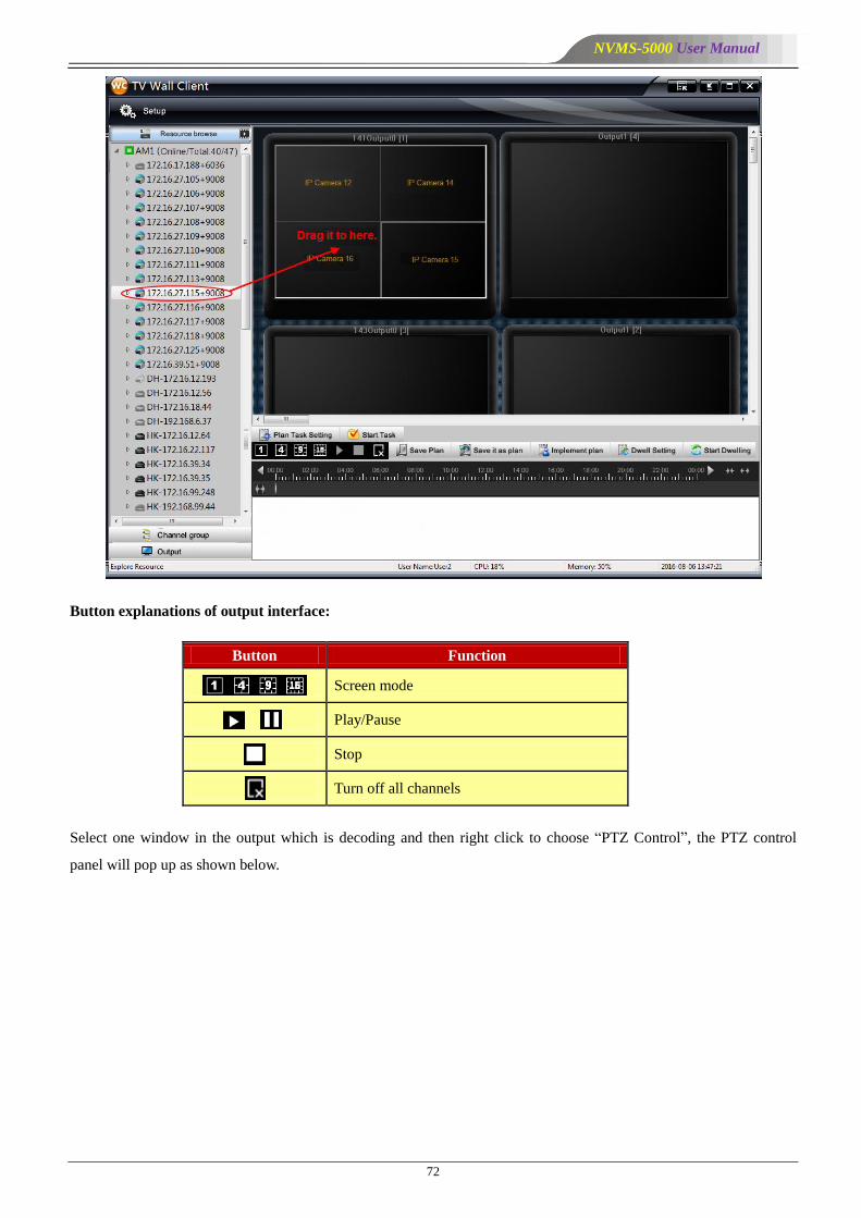
NVMS-5000 User Manual
72
Button explanations of output interface:
Button Function
Screen mode
Play/Pause
Stop
Turn off all channels
Select one window in the output which is decoding and then right click to choose ―PTZ Control‖, the PTZ control
panel will pop up as shown below.
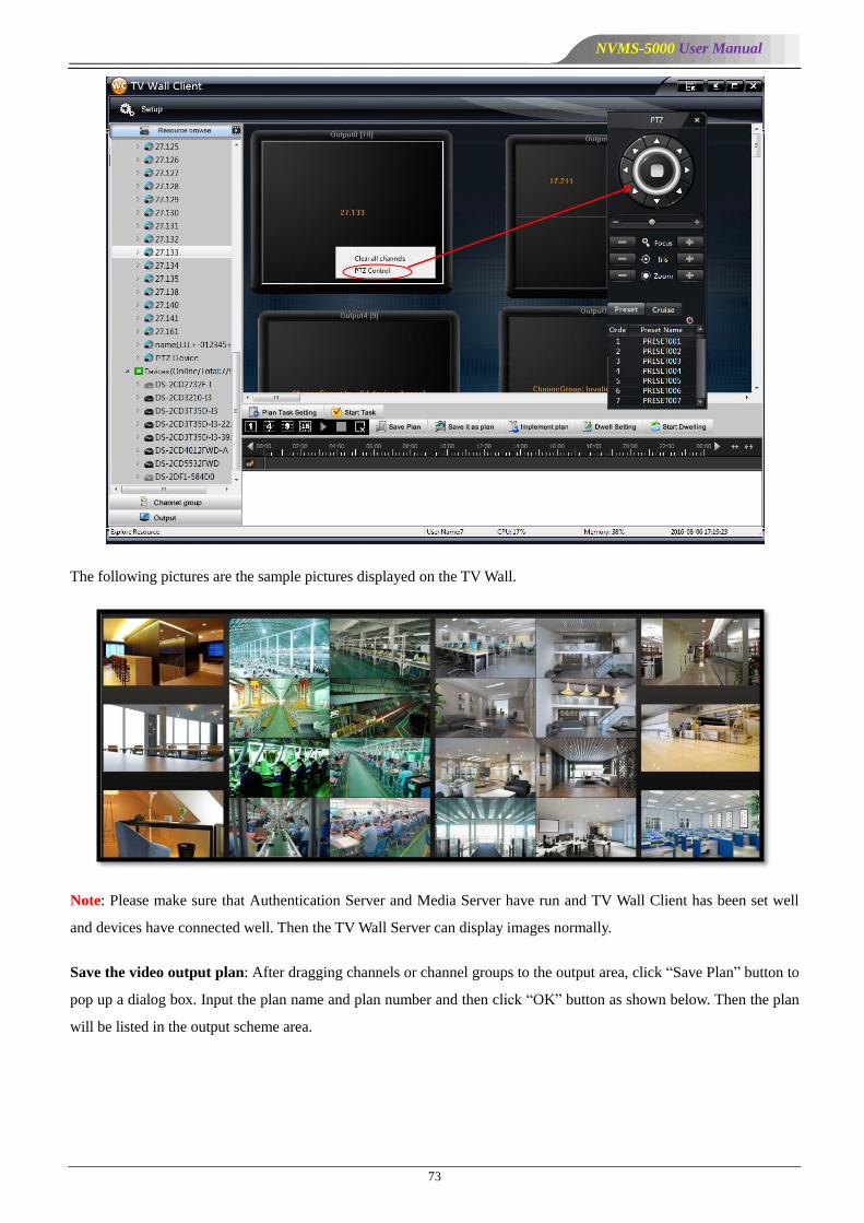
NVMS-5000 User Manual
73
The following pictures are the sample pictures displayed on the TV Wall.
Note: Please make sure that Authentication Server and Media Server have run and TV Wall Client has been set well
and devices have connected well. Then the TV Wall Server can display images normally.
Save the video output plan: After dragging channels or channel groups to the output area, click ―Save Plan‖ button to
pop up a dialog box. Input the plan name and plan number and then click ―OK‖ button as shown below. Then the plan
will be listed in the output scheme area.
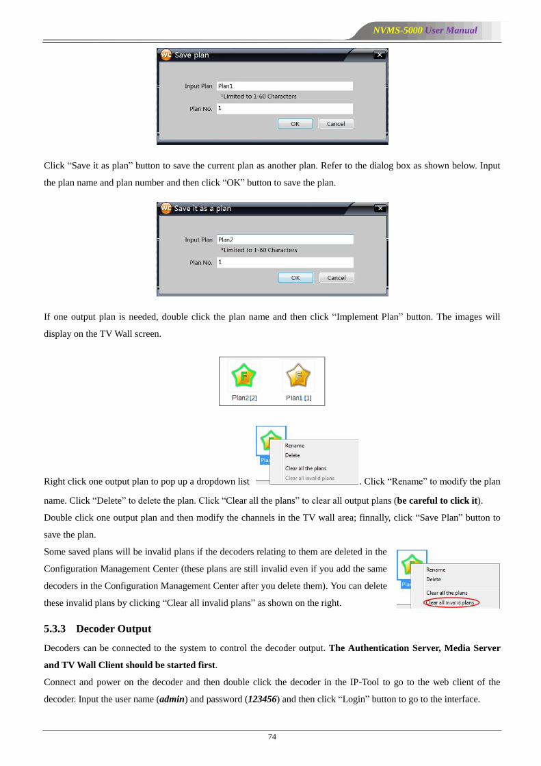
NVMS-5000 User Manual
74
Click ―Save it as plan‖ button to save the current plan as another plan. Refer to the dialog box as shown below. Input
the plan name and plan number and then click ―OK‖ button to save the plan.
If one output plan is needed, double click the plan name and then click ―Implement Plan‖ button. The images will
display on the TV Wall screen.
Right click one output plan to pop up a dropdown list . Click ―Rename‖ to modify the plan
name. Click ―Delete‖ to delete the plan. Click ―Clear all the plans‖ to clear all output plans (be careful to click it).
Double click one output plan and then modify the channels in the TV wall area; finnally, click ―Save Plan‖ button to
save the plan.
Some saved plans will be invalid plans if the decoders relating to them are deleted in the
Configuration Management Center (these plans are still invalid even if you add the same
decoders in the Configuration Management Center after you delete them). You can delete
these invalid plans by clicking ―Clear all invalid plans‖ as shown on the right.
5.3.3 Decoder Output
Decoders can be connected to the system to control the decoder output. The Authentication Server, Media Server
and TV Wall Client should be started first.
Connect and power on the decoder and then double click the decoder in the IP-Tool to go to the web client of the
decoder. Input the user name (admin) and password (123456) and then click ―Login‖ button to go to the interface.
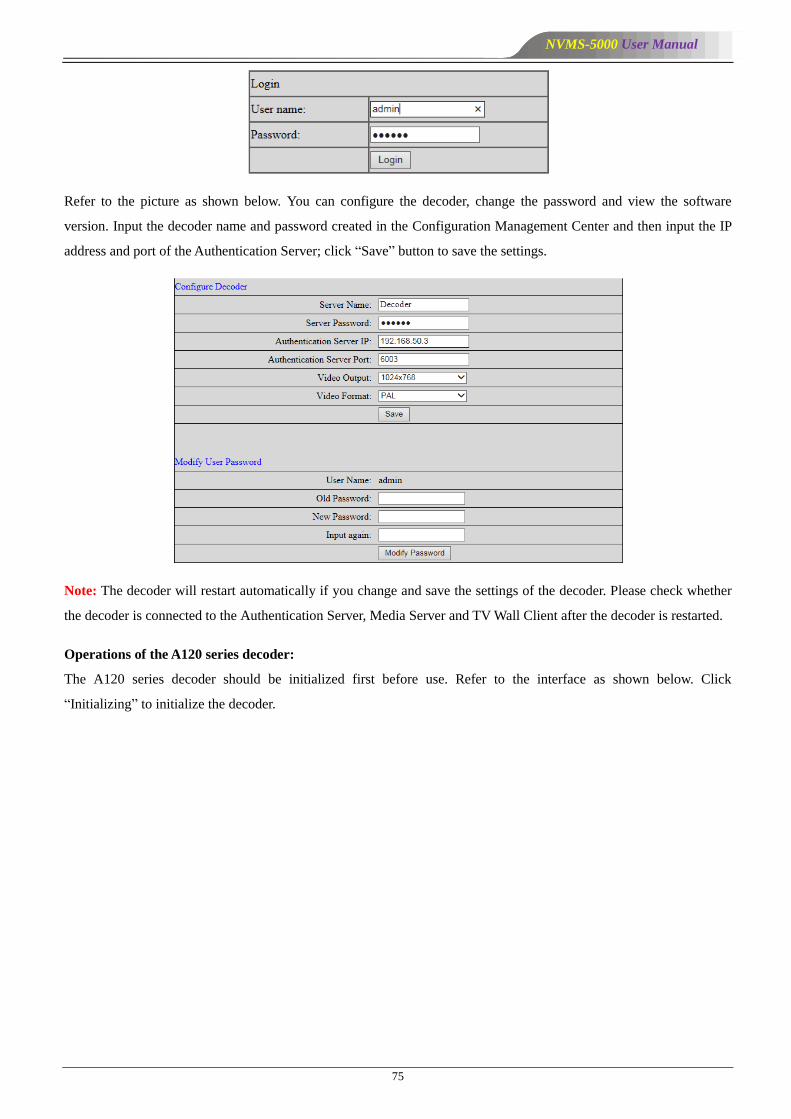
NVMS-5000 User Manual
75
Refer to the picture as shown below. You can configure the decoder, change the password and view the software
version. Input the decoder name and password created in the Configuration Management Center and then input the IP
address and port of the Authentication Server; click ―Save‖ button to save the settings.
Note: The decoder will restart automatically if you change and save the settings of the decoder. Please check whether
the decoder is connected to the Authentication Server, Media Server and TV Wall Client after the decoder is restarted.
Operations of the A120 series decoder:
The A120 series decoder should be initialized first before use. Refer to the interface as shown below. Click
―Initializing‖ to initialize the decoder.
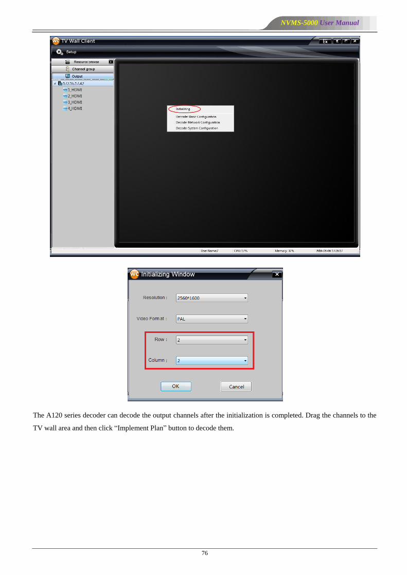
NVMS-5000 User Manual
76
The A120 series decoder can decode the output channels after the initialization is completed. Drag the channels to the
TV wall area and then click ―Implement Plan‖ button to decode them.
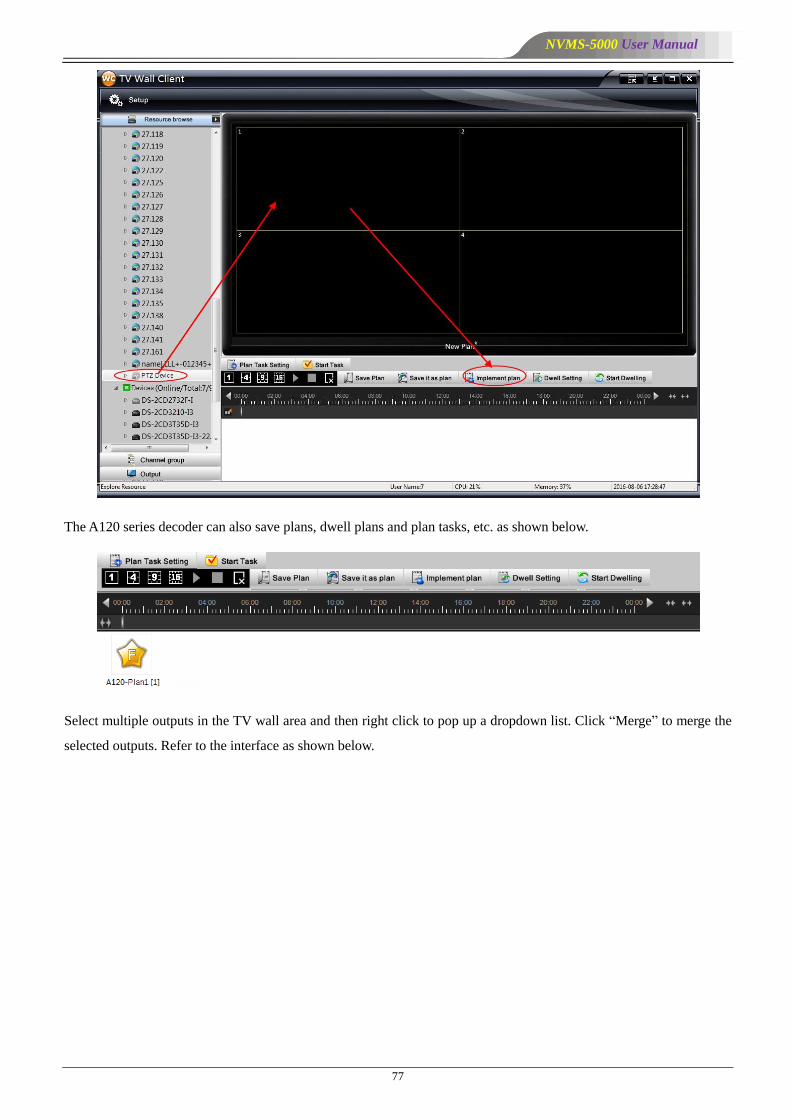
NVMS-5000 User Manual
77
The A120 series decoder can also save plans, dwell plans and plan tasks, etc. as shown below.
Select multiple outputs in the TV wall area and then right click to pop up a dropdown list. Click ―Merge‖ to merge the
selected outputs. Refer to the interface as shown below.

NVMS-5000 User Manual
78
You can also recover the merged outputs to the state before merging by
clicking ―Recover‖. Refer to the picture as shown on the right.
Click ―Alarm Pop-up Configuration‖ and then draw the alarm popup window manually to complete the configuration.
Refer to the picture as shown below. You can also delete the alarm popup window.
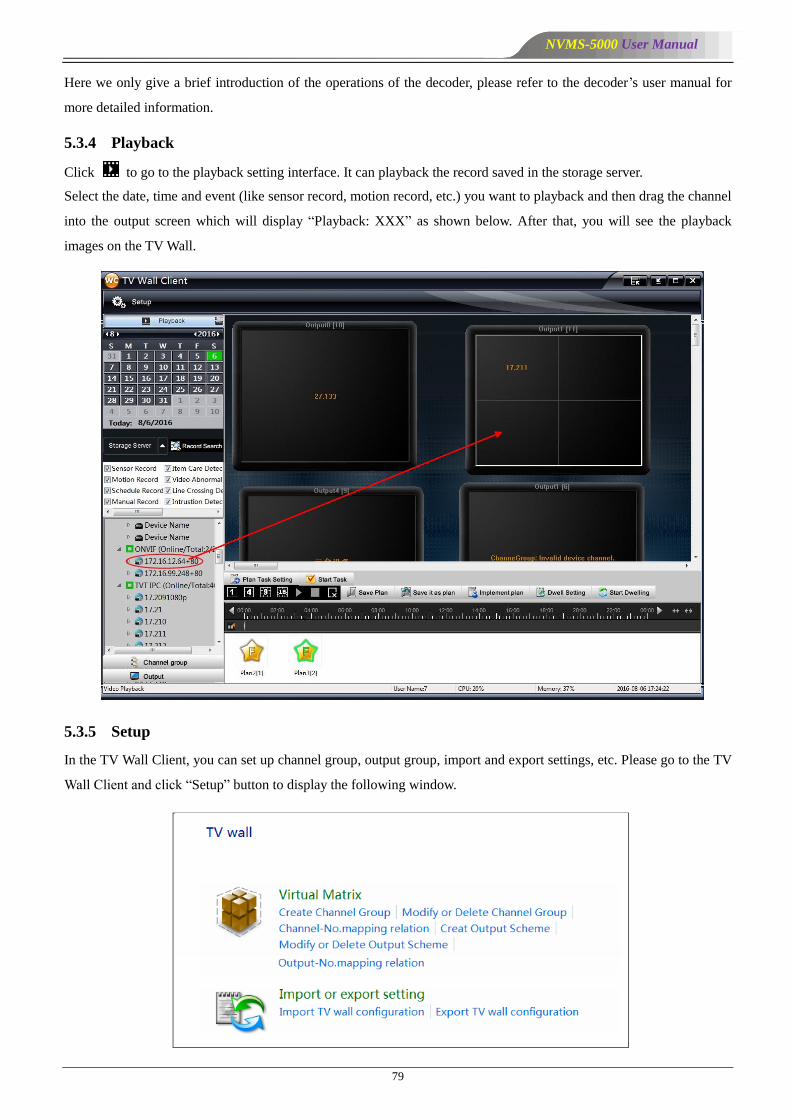
NVMS-5000 User Manual
79
Here we only give a brief introduction of the operations of the decoder, please refer to the decoder’s user manual for
more detailed information.
5.3.4 Playback
Click to go to the playback setting interface. It can playback the record saved in the storage server.
Select the date, time and event (like sensor record, motion record, etc.) you want to playback and then drag the channel
into the output screen which will display ―Playback: XXX‖ as shown below. After that, you will see the playback
images on the TV Wall.
5.3.5 Setup
In the TV Wall Client, you can set up channel group, output group, import and export settings, etc. Please go to the TV
Wall Client and click ―Setup‖ button to display the following window.

NVMS-5000 User Manual
80
5.3.5.1 Create or Delete Channel Group
Go to TV Wall Client Setup interface. Click ―Virtual Matrix‖ button to go to the interface.
Channel group setting steps:
① Click ―Create Channel Group‖ button to create a channel group. Input the channel group name, number and select
the dwell time and then click ―OK‖ button to save the settings.
② Select a channel group and click ―Modify‖ button.
③ Select ―Add or remove channels in the channel group‖ to go to the interface as shown below.
Select the channel in the lower area and then click icon to add the channel to the channel group. Select the channel
in the upper area and click icon to remove the channel from the channel group.
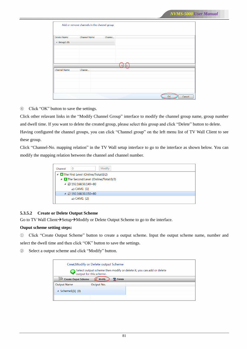
NVMS-5000 User Manual
81
④ Click ―OK‖ button to save the settings.
Click other relavant links in the ―Modify Channel Group‖ interface to modify the channel group name, group number
and dwell time. If you want to delete the created group, please select this group and click ―Delete‖ button to delete.
Having configured the channel groups, you can click ―Channel group‖ on the left menu list of TV Wall Client to see
these group.
Click ―Channel-No. mapping relation‖ in the TV Wall setup interface to go to the interface as shown below. You can
modify the mapping relation between the channel and channel number.
5.3.5.2 Create or Delete Output Scheme
Go to TV Wall ClientSetupModify or Delete Output Scheme to go to the interface.
Ouput scheme setting steps:
① Click ―Create Output Scheme‖ button to create a output scheme. Input the output scheme name, number and
select the dwell time and then click ―OK‖ button to save the settings.
② Select a output scheme and click ―Modify‖ button.
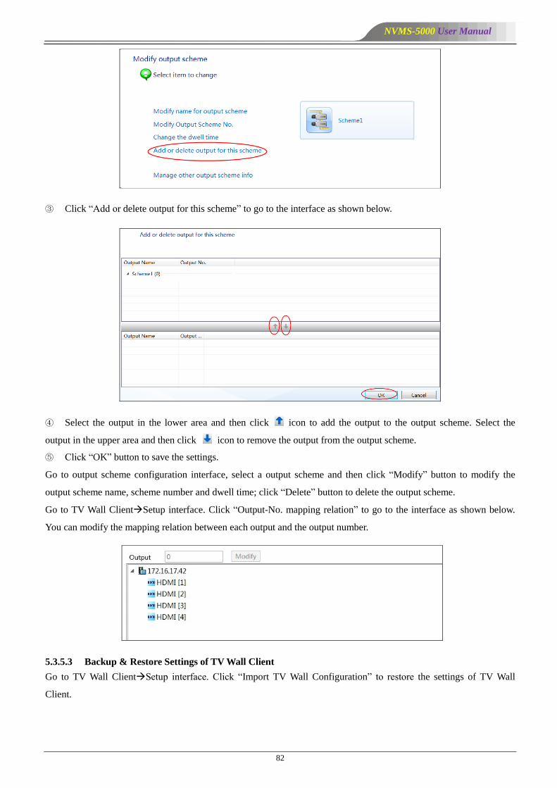
NVMS-5000 User Manual
82
③ Click ―Add or delete output for this scheme‖ to go to the interface as shown below.
④ Select the output in the lower area and then click icon to add the output to the output scheme. Select the
output in the upper area and then click icon to remove the output from the output scheme.
⑤ Click ―OK‖ button to save the settings.
Go to output scheme configuration interface, select a output scheme and then click ―Modify‖ button to modify the
output scheme name, scheme number and dwell time; click ―Delete‖ button to delete the output scheme.
Go to TV Wall ClientSetup interface. Click ―Output-No. mapping relation‖ to go to the interface as shown below.
You can modify the mapping relation between each output and the output number.
5.3.5.3 Backup & Restore Settings of TV Wall Client
Go to TV Wall ClientSetup interface. Click ―Import TV Wall Configuration‖ to restore the settings of TV Wall
Client.
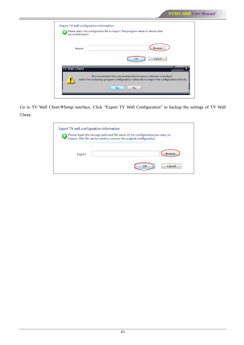
NVMS-5000 User Manual
83
Go to TV Wall ClientSetup interface. Click ―Export TV Wall Configuration‖ to backup the settings of TV Wall
Client.
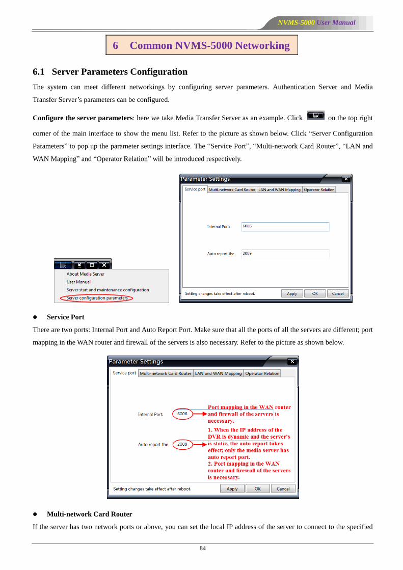
NVMS-5000 User Manual
84
6.1 Server Parameters Configuration
The system can meet different networkings by configuring server parameters. Authentication Server and Media
Transfer Server’s parameters can be configured.
Configure the server parameters: here we take Media Transfer Server as an example. Click on the top right
corner of the main interface to show the menu list. Refer to the picture as shown below. Click ―Server Configuration
Parameters‖ to pop up the parameter settings interface. The ―Service Port‖, ―Multi-network Card Router‖, ―LAN and
WAN Mapping‖ and ―Operator Relation‖ will be introduced respectively.
Service Port
There are two ports: Internal Port and Auto Report Port. Make sure that all the ports of all the servers are different; port
mapping in the WAN router and firewall of the servers is also necessary. Refer to the picture as shown below.
Multi-network Card Router
If the server has two network ports or above, you can set the local IP address of the server to connect to the specified
6 Common NVMS-5000 Networking
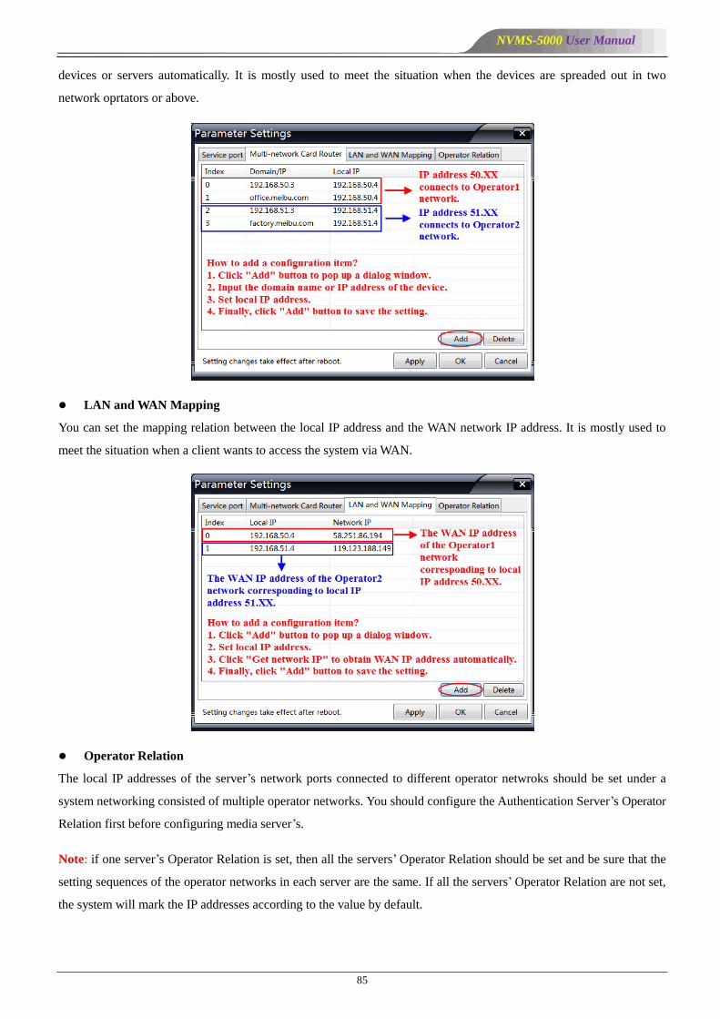
NVMS-5000 User Manual
85
devices or servers automatically. It is mostly used to meet the situation when the devices are spreaded out in two
network oprtators or above.
LAN and WAN Mapping
You can set the mapping relation between the local IP address and the WAN network IP address. It is mostly used to
meet the situation when a client wants to access the system via WAN.
Operator Relation
The local IP addresses of the server’s network ports connected to different operator netwroks should be set under a
system networking consisted of multiple operator networks. You should configure the Authentication Server’s Operator
Relation first before configuring media server’s.
Note: if one server’s Operator Relation is set, then all the servers’ Operator Relation should be set and be sure that the
setting sequences of the operator networks in each server are the same. If all the servers’ Operator Relation are not set,
the system will mark the IP addresses according to the value by default.
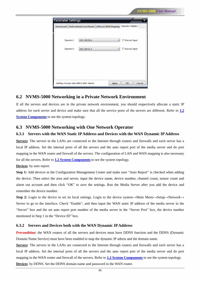
NVMS-5000 User Manual
86
6.2 NVMS-5000 Networking in a Private Network Environment
If all the servers and devices are in the private network environment, you should respectively allocate a static IP
address for each server and device and make sure that all the service ports of the servers are different. Refer to 1.2
System Components to see the system topology.
6.3 NVMS-5000 Networking with One Network Operator
6.3.1 Servers with the WAN Static IP Address and Devices with the WAN Dynamic IP Address
Servers: The servers in the LANs are connected to the Internet through routers and firewalls and each server has a
local IP address. Set the internal ports of all the servers and the auto report port of the media server and do port
mapping in the WAN router and firewall of the servers. The configuration of LAN and WAN mapping is also necessary
for all the servers. Refer to 1.2 System Components to see the system topology.
Devices: by auto report.
Step 1: Add devices in the Configuration Management Center and make sure ―Auto Report‖ is checked when adding
the device. Then select the area and server, input the device name, device number, channel count, sensor count and
alarm out account and then click ―OK‖ to save the settings. Run the Media Server after you add the device and
remember the device number.
Step 2: Login to the device to set its local settings. Login to the device system→Main Menu→Setup→Network→
Server to go to the interface. Check ―Enable‖, and then input the WAN static IP address of the media server in the
―Server‖ box and the set auto report port number of the media server in the ―Server Port‖ box, the device number
mentioned in Step 1 in the ―Device ID‖ box.
6.3.2 Servers and Devices both with the WAN Dynamic IP Address
Precondition: the WAN routers of all the servers and devices must have DDNS function and the DDNS (Dynamic
Domain Name Service) must have been enabled to map the dynamic IP adress and the domain name.
Servers: The servers in the LANs are connected to the Internet through routers and firewalls and each server has a
local IP address. Set the internal ports of all the servers and the auto report port of the media server and do port
mapping in the WAN router and firewall of the servers. Refer to 1.2 System Components to see the system topology.
Devices: by DDNS. Set the DDNS domain name and password in the WAN router.
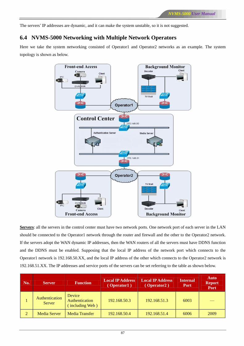
NVMS-5000 User Manual
87
The servers’ IP addresses are dynamic, and it can make the system unstable, so it is not suggested.
6.4 NVMS-5000 Networking with Multiple Network Operators
Here we take the system networking consisted of Operator1 and Operator2 networks as an example. The system
topology is shown as below.
Servers: all the servers in the control center must have two network ports. One network port of each server in the LAN
should be connected to the Operator1 network through the router and firewall and the other to the Operator2 network.
If the servers adopt the WAN dynamic IP addresses, then the WAN routers of all the servers must have DDNS function
and the DDNS must be enabled. Supposing that the local IP address of the network port which connects to the
Operator1 network is 192.168.50.XX, and the local IP address of the other which connects to the Operator2 network is
192.168.51.XX. The IP addresses and service ports of the servers can be set referring to the table as shown below.
No. Server Function Local IP Address
( Operator1 )
Local IP Address
( Operator2 )
Internal
Port
Auto
Report
Port
1 Authentication
Server
Device
Authentication
( including Web )
192.168.50.3 192.168.51.3 6003 —
2 Media Server Media Transfer 192.168.50.4 192.168.51.4 6006 2009
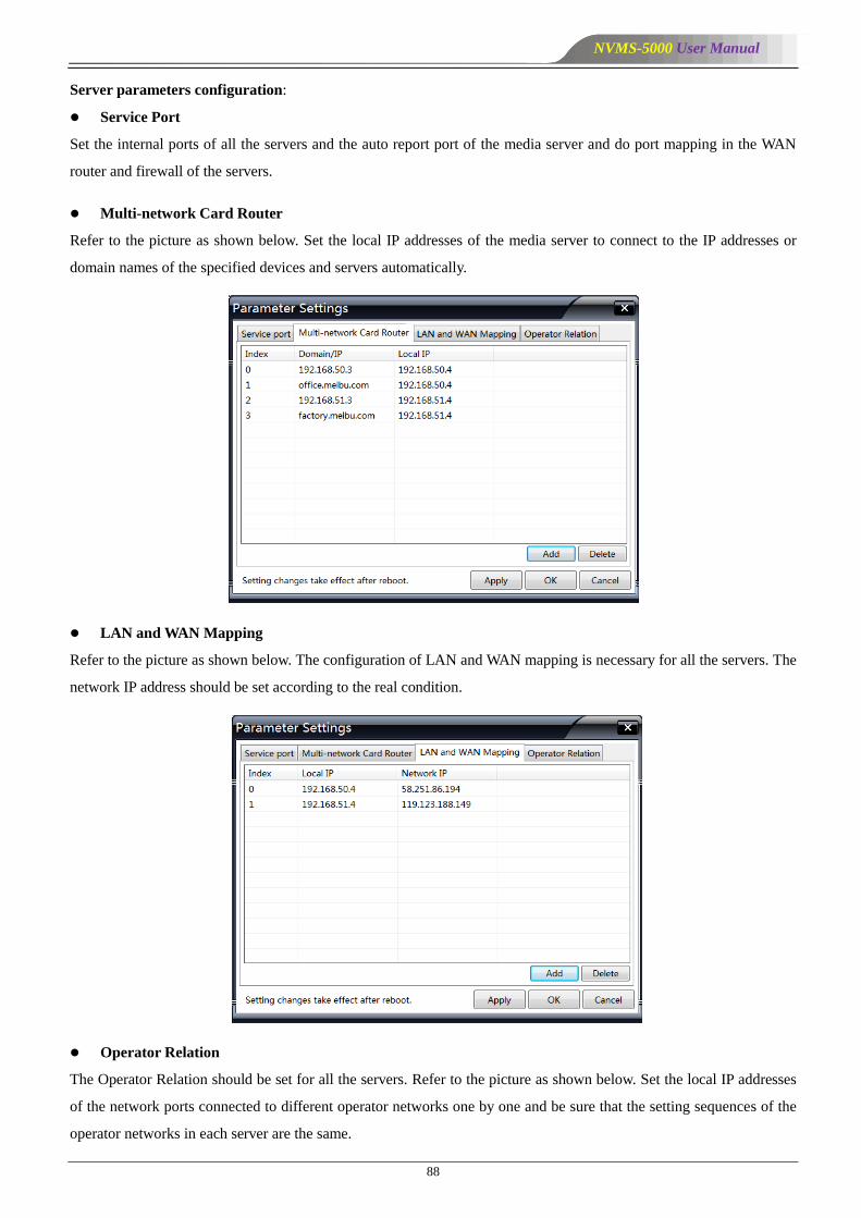
NVMS-5000 User Manual
88
Server parameters configuration:
Service Port
Set the internal ports of all the servers and the auto report port of the media server and do port mapping in the WAN
router and firewall of the servers.
Multi-network Card Router
Refer to the picture as shown below. Set the local IP addresses of the media server to connect to the IP addresses or
domain names of the specified devices and servers automatically.
LAN and WAN Mapping
Refer to the picture as shown below. The configuration of LAN and WAN mapping is necessary for all the servers. The
network IP address should be set according to the real condition.
Operator Relation
The Operator Relation should be set for all the servers. Refer to the picture as shown below. Set the local IP addresses
of the network ports connected to different operator networks one by one and be sure that the setting sequences of the
operator networks in each server are the same.
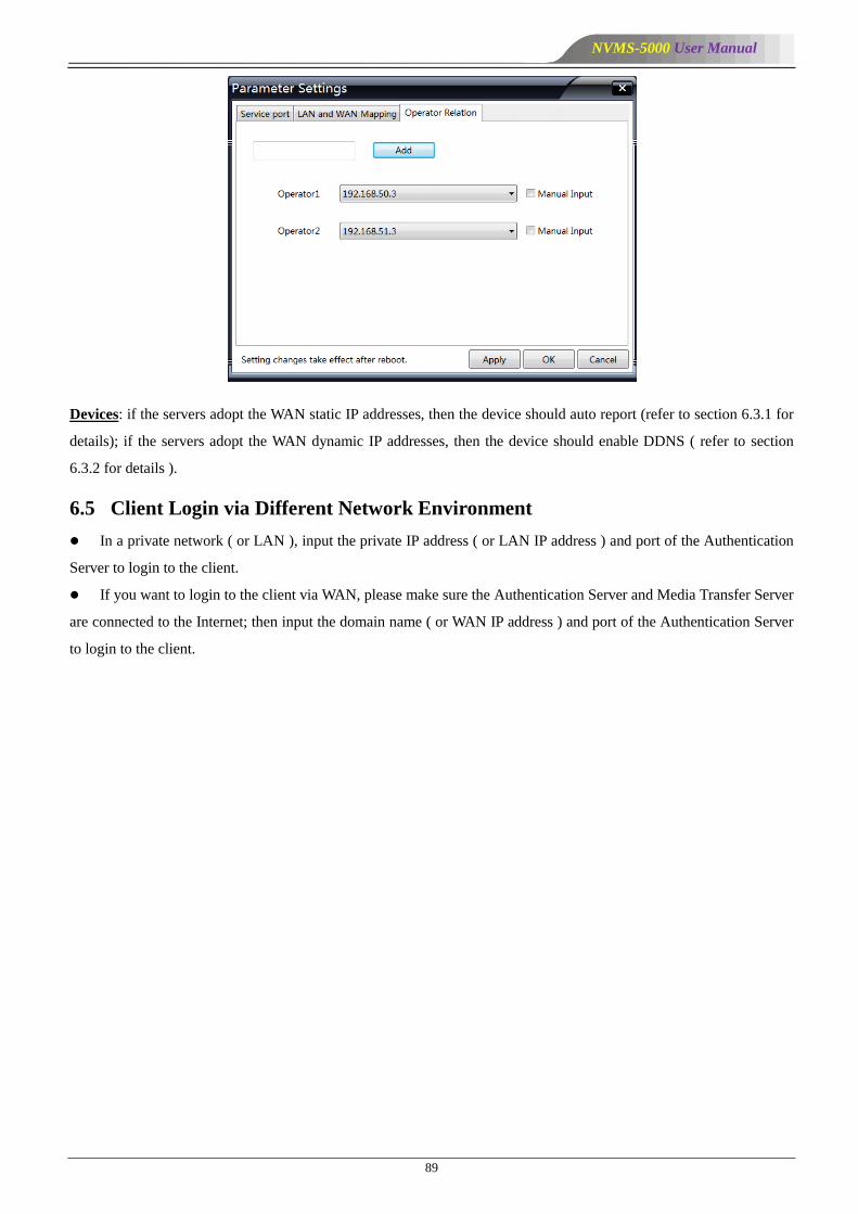
NVMS-5000 User Manual
89
Devices: if the servers adopt the WAN static IP addresses, then the device should auto report (refer to section 6.3.1 for
details); if the servers adopt the WAN dynamic IP addresses, then the device should enable DDNS ( refer to section
6.3.2 for details ).
6.5 Client Login via Different Network Environment
In a private network ( or LAN ), input the private IP address ( or LAN IP address ) and port of the Authentication
Server to login to the client.
If you want to login to the client via WAN, please make sure the Authentication Server and Media Transfer Server
are connected to the Internet; then input the domain name ( or WAN IP address ) and port of the Authentication Server
to login to the client.
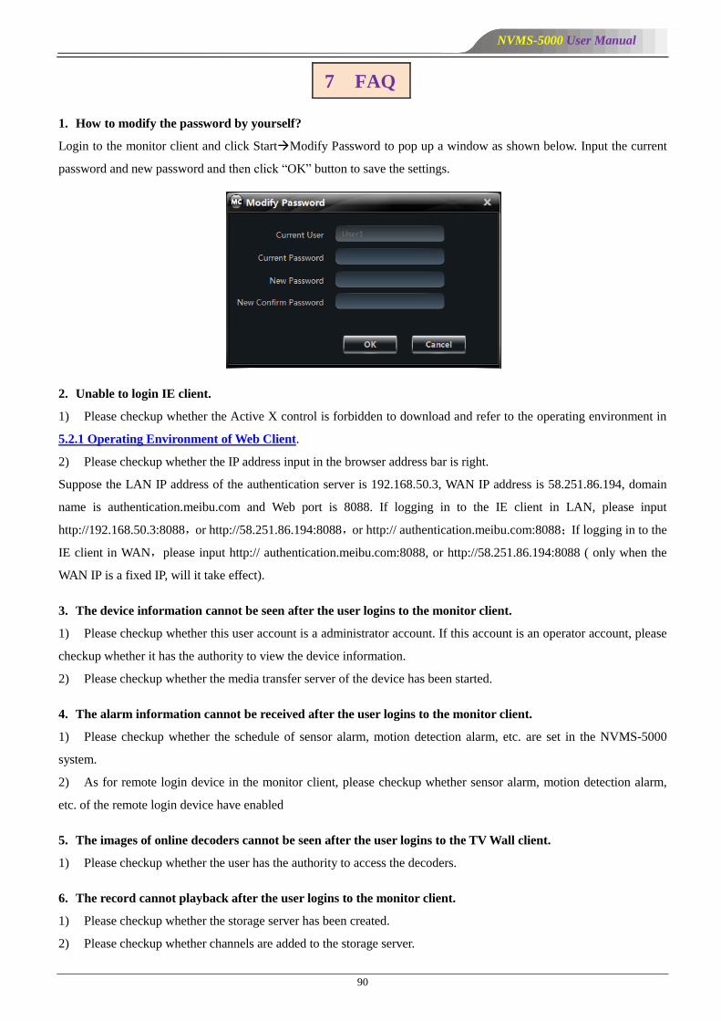
NVMS-5000 User Manual
90
1. How to modify the password by yourself?
Login to the monitor client and click StartModify Password to pop up a window as shown below. Input the current
password and new password and then click ―OK‖ button to save the settings.
2. Unable to login IE client.
1) Please checkup whether the Active X control is forbidden to download and refer to the operating environment in
5.2.1 Operating Environment of Web Client.
2) Please checkup whether the IP address input in the browser address bar is right.
Suppose the LAN IP address of the authentication server is 192.168.50.3, WAN IP address is 58.251.86.194, domain
name is authentication.meibu.com and Web port is 8088. If logging in to the IE client in LAN, please input
http://192.168.50.3:8088,or http://58.251.86.194:8088,or http:// authentication.meibu.com:8088;If logging in to the
IE client in WAN,please input http:// authentication.meibu.com:8088, or http://58.251.86.194:8088 ( only when the
WAN IP is a fixed IP, will it take effect).
3. The device information cannot be seen after the user logins to the monitor client.
1) Please checkup whether this user account is a administrator account. If this account is an operator account, please
checkup whether it has the authority to view the device information.
2) Please checkup whether the media transfer server of the device has been started.
4. The alarm information cannot be received after the user logins to the monitor client.
1) Please checkup whether the schedule of sensor alarm, motion detection alarm, etc. are set in the NVMS-5000
system.
2) As for remote login device in the monitor client, please checkup whether sensor alarm, motion detection alarm,
etc. of the remote login device have enabled
5. The images of online decoders cannot be seen after the user logins to the TV Wall client.
1) Please checkup whether the user has the authority to access the decoders.
6. The record cannot playback after the user logins to the monitor client.
1) Please checkup whether the storage server has been created.
2) Please checkup whether channels are added to the storage server.
7 FAQ

NVMS-5000 User Manual
91
3) Please checkup the record schedules of the storage server are set correctly.
7. The configuration of devices cannot be modified remotely after the user logins to the monitor client.
1) When the device configuration is required by the monitor client and pop up the prompt ―Someone is configuring.
Please try later‖, please open the IE browser to login to the device remotely and then go to ―Info‖ ―Online user‖
interface to see if there are any other users logging in.
2) Please go to the live to see whether the device is setting up.
3) If the problem still exists, please contact your device manufacturer.
8. The preview image on the client cannot display fluently.
1) Please check whether the CPU occupancy rate of the client platform is 100% or there still has usable memory.
This situation will not emerge when the CPU occupancy rate is less than 75% and there still has usable memory.
2) Please checkup whether the network environment is supported, including whether the uplink bandwidth of the
device and stream match and whether the downlink bandwidths of the media transfer server and the streams of all
channels of devices match.
3) Please checkup whether the media transfer server is overload operation.
9. After starting the authentication server and media transfer server, the storage server still cannot save.
1) Please checkup whether channels of devices are added to the storage server.
10. Why does the PTZ control interface is blank after the user goes to the monitor client?
You need to drag channels to the live preview area and then operate in the PTZ control interface.


![[刘毅5000词汇] 5000](https://img.pdfslide.tips/doc/110x75/577dae3f1a28ab223f9031b1/5000-5000.jpg)