Embed Size (px)
Citation preview
dbf5512a0600p_04 1 / 20
Manufacturer:
H-1043 Budapest, Dugonics u. 11.Phone: (36-1) 889-0100 Fax: (36-1) 889-0200
sales
NIVELCO Process Control Co.
E-mail: @nivelco.com www.nivelco.com
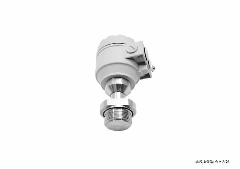
NIVOPRESSDT- and DB- pressure transmitter and
pressure transmitter for level
2 / 20 dbf5512a0600p_04
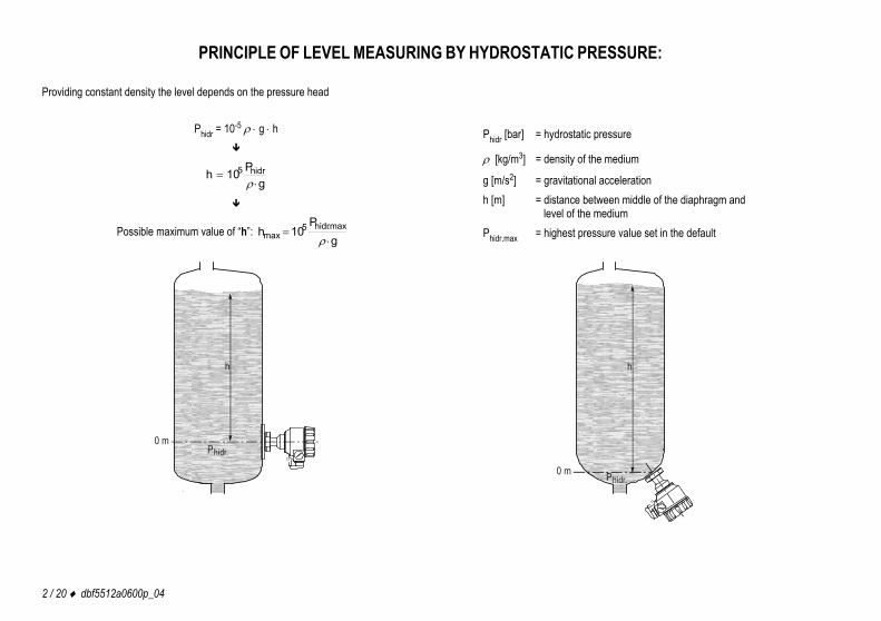
PRINCIPLE OF LEVEL MEASURING BY HYDROSTATIC PRESSURE: Providing constant density the level depends on the pressure head
Phidr = 10-5 g h
gP10h hidr5
Possible maximum value of “h”: g
P10h max.hidr5
max
Phidr [bar] = hydrostatic pressure
[kg/m3] = density of the medium
g [m/s2] = gravitational acceleration h [m] = distance between middle of the diaphragm and
level of the medium Phidr.max = highest pressure value set in the default
h
0 mPhidr.
h
0 m Phidr.
dbf5512a0600p_04 3 / 20

4 / 20 dbf5512a0600p_04
dbf5512a0600p_04 5 / 20
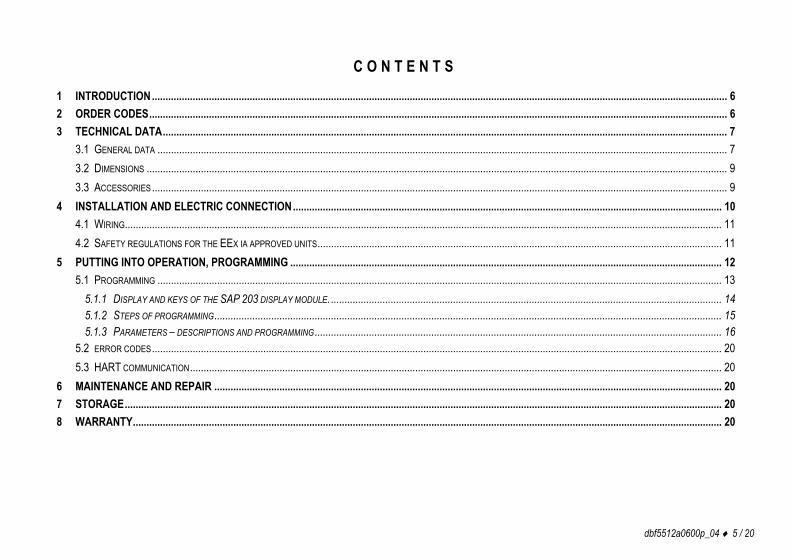
C O N T E N T S 1 INTRODUCTION.................................................................................................................................................................................................................... 6 2 ORDER CODES..................................................................................................................................................................................................................... 6 3 TECHNICAL DATA................................................................................................................................................................................................................ 7
3.1 GENERAL DATA .................................................................................................................................................................................................................. 7 3.2 DIMENSIONS ...................................................................................................................................................................................................................... 9 3.3 ACCESSORIES.................................................................................................................................................................................................................... 9
4 INSTALLATION AND ELECTRIC CONNECTION.............................................................................................................................................................. 10 4.1 WIRING............................................................................................................................................................................................................................ 11 4.2 SAFETY REGULATIONS FOR THE EEX IA APPROVED UNITS..................................................................................................................................................... 11
5 PUTTING INTO OPERATION, PROGRAMMING ............................................................................................................................................................... 12 5.1 PROGRAMMING ................................................................................................................................................................................................................ 13
5.1.1 DISPLAY AND KEYS OF THE SAP 203 DISPLAY MODULE. ................................................................................................................................................ 14 5.1.2 STEPS OF PROGRAMMING........................................................................................................................................................................................... 15 5.1.3 PARAMETERS – DESCRIPTIONS AND PROGRAMMING...................................................................................................................................................... 16
5.2 ERROR CODES.................................................................................................................................................................................................................. 20 5.3 HART COMMUNICATION.................................................................................................................................................................................................... 20
6 MAINTENANCE AND REPAIR ........................................................................................................................................................................................... 20 7 STORAGE............................................................................................................................................................................................................................ 20 8 WARRANTY......................................................................................................................................................................................................................... 20
6 / 20 dbf5512a0600p_04
Thank you for choosing NIVELCO instrument We are sure that you will be satisfied throughout its use!
1 INTRODUCTION NIVOPRESS D-5/600 series transmitters are suitable for pressure and hydrostatic pressure (level) gauging of ordinary and hazardous gases, fumes, liquids and masses. Devices can be used for measuring in clean technologies and also for mediums tending to obturation. Intelligent electronics and HART communication provides application possibilities for the most different tasks.
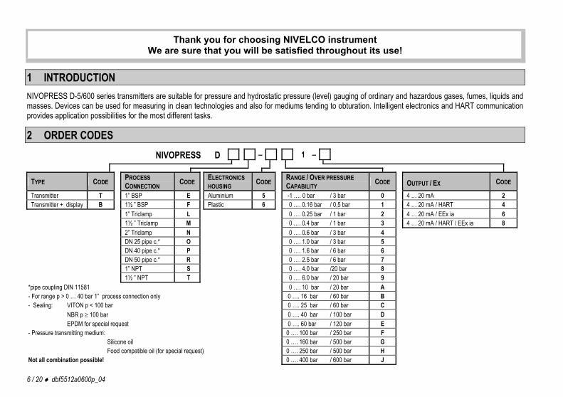
2 ORDER CODES NIVOPRESS D – 1 –
TYPE CODE PROCESS CONNECTION CODE ELECTRONICS
HOUSING CODE RANGE / OVER PRESSURE CAPABILITY CODE OUTPUT / EX CODE
Transmitter T 1” BSP E Aluminium 5 -1 …. 0 bar / 3 bar 0 4 … 20 mA 2 Transmitter + display B 1½ ” BSP F Plastic 6 0 …. 0.16 bar / 0,5 bar 1 4 … 20 mA / HART 4 1” Triclamp L 0 …. 0.25 bar / 1 bar 2 4 … 20 mA / EEx ia 6 1½ ” Triclamp M 0 …. 0.4 bar / 1 bar 3 4 … 20 mA / HART / EEx ia 8 2” Triclamp N 0 …. 0.6 bar / 3 bar 4 DN 25 pipe c.* O 0 …. 1.0 bar / 3 bar 5 DN 40 pipe c.* P 0 …. 1.6 bar / 6 bar 6 DN 50 pipe c.* R 0 …. 2.5 bar / 6 bar 7 1” NPT S 0 …. 4.0 bar /20 bar 8 1½ ” NPT T 0 …. 6.0 bar / 20 bar 9
*pipe coupling DIN 11581 0 …. 10 bar / 20 bar A - For range p > 0 … 40 bar 1” process connection only 0 …. 16 bar / 60 bar B - Sealing: VITON p < 100 bar 0 …. 25 bar / 60 bar C NBR p 100 bar 0 …. 40 bar / 100 bar D EPDM for special request 0 …. 60 bar / 120 bar E - Pressure transmitting medium: 0 …. 100 bar / 250 bar F Silicone oil 0 …. 160 bar / 500 bar G Food compatible oil (for special request) 0 …. 250 bar / 500 bar H Not all combination possible! 0 …. 400 bar / 600 bar J
dbf5512a0600p_04 7 / 20
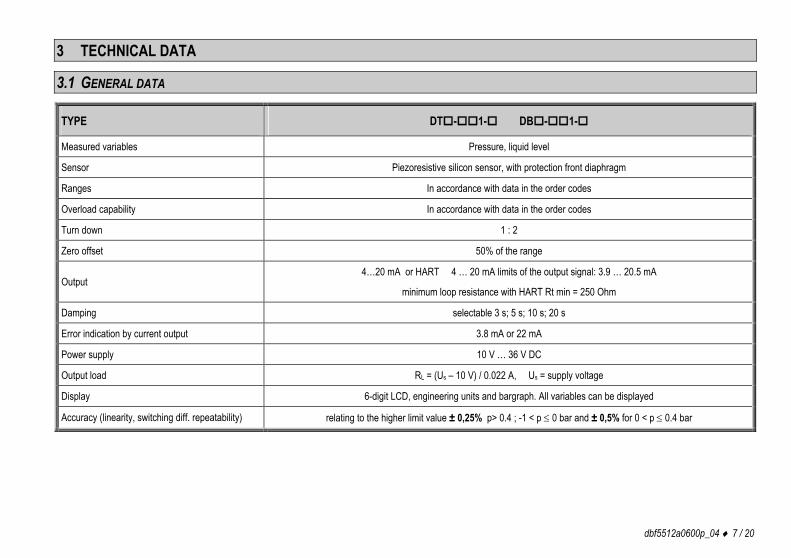
3 TECHNICAL DATA
3.1 GENERAL DATA
TYPE DT-1- DB-1-
Measured variables Pressure, liquid level
Sensor Piezoresistive silicon sensor, with protection front diaphragm
Ranges In accordance with data in the order codes
Overload capability In accordance with data in the order codes
Turn down 1 : 2
Zero offset 50% of the range
Output 4…20 mA or HART 4 … 20 mA limits of the output signal: 3.9 … 20.5 mA
minimum loop resistance with HART Rt min = 250 Ohm
Damping selectable 3 s; 5 s; 10 s; 20 s
Error indication by current output 3.8 mA or 22 mA
Power supply 10 V … 36 V DC
Output load RL = (Us – 10 V) / 0.022 A, Us = supply voltage
Display 6-digit LCD, engineering units and bargraph. All variables can be displayed
Accuracy (linearity, switching diff. repeatability) relating to the higher limit value ± 0,25% p> 0.4 ; -1 < p 0 bar and ± 0,5% for 0 < p 0.4 bar
8 / 20 dbf5512a0600p_04
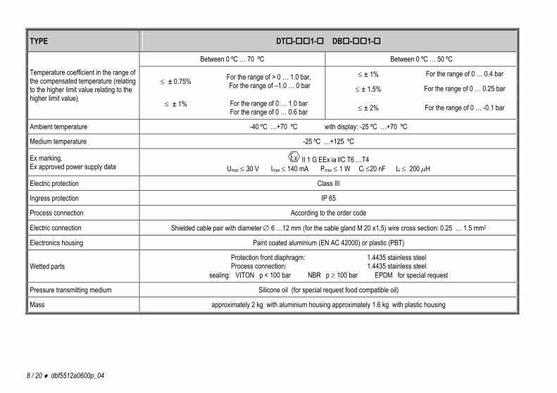
TYPE DT-1- DB-1-
Between 0 ºC … 70 ºC Between 0 ºC … 50 ºC
± 1% For the range of 0 … 0.4 bar ± 0.75% For the range of > 0 … 1.0 bar,
For the range of –1.0 … 0 bar ± 1.5% For the range of 0 … 0.25 bar
Temperature coefficient in the range of the compensated temperature (relating to the higher limit value relating to the higher limit value)
± 1% For the range of 0 … 1.0 bar For the range of 0 … 0.6 bar ± 2% For the range of 0 … -0.1 bar
Ambient temperature -40 ºC …+70 ºC with display: -25 ºC …+70 ºC
Medium temperature -25 ºC …+125 ºC
Ex marking, Ex approved power supply data
II 1 G EEx ia IIC T6 …T4 Umax 30 V Imax 140 mA Pmax 1 W Ci 20 nF Li 200 H
Electric protection Class III
Ingress protection IP 65
Process connection According to the order code
Electric connection Shielded cable pair with diameter 6 …12 mm (for the cable gland M 20 x1,5) wire cross section: 0.25 … 1.5 mm2
Electronics housing Paint coated aluminium (EN AC 42000) or plastic (PBT)
Wetted parts Protection front diaphragm: 1.4435 stainless steel Process connection: 1.4435 stainless steel
sealing: VITON p < 100 bar NBR p 100 bar EPDM for special request
Pressure transmitting medium Silicone oil (for special request food compatible oil)
Mass approximately 2 kg with aluminium housing approximately 1.6 kg with plastic housing
dbf5512a0600p_04 9 / 20
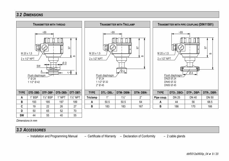
3.2 DIMENSIONS
TRANSMITTER WITH THREAD TRANSMITTER WITH TRICLAMP TRANSMITTER WITH PIPE COUPLING (DIN11581)
~89
97B
Ø D
CSW
AFlush diaphragm1" 281 1/2" 42
ØØ
M 20 x 1,5
2 x 1/2" NPT
~89
97B
Ø AFlush diaphragm1" 241 1/2" 32
" 45
2
ØØ
Ø
M 20 x 1,5
2 x 1/2" NPT
~89
97B
Ø AFlush diaphragmDN25 24DN40 32DN50 45
ØØØ
M 20 x 1,5
2 x 1/2" NPT
TYPE DTE- DBE- DTF- DBF- DTS- DBS- DTT- DBT- TYPE DTL- DBL- DTM- DBM- DTN- DBN- TYPE DTO-, DBO- DTP-, DBP- DTR-, DBR-A 1” BSP 1½” BSP 1” NPT 1½” NPT Triclamp 1” 1½” 2” Pipe coup. DN 25 DN 40 DN 50 B 193 185 197 189 A 50.5 50.5 64 A 44 56 68.5 C 19 22 26 27 B 183 183 167 B 186 170 166 D 50 65 52 70
SW 44 55 40 55 Dimensions in mm
3.3 ACCESSORIES – Installation and Programming Manual – Certificate of Warranty – Declaration of Conformity – 2 cable glands
10 / 20 dbf5512a0600p_04
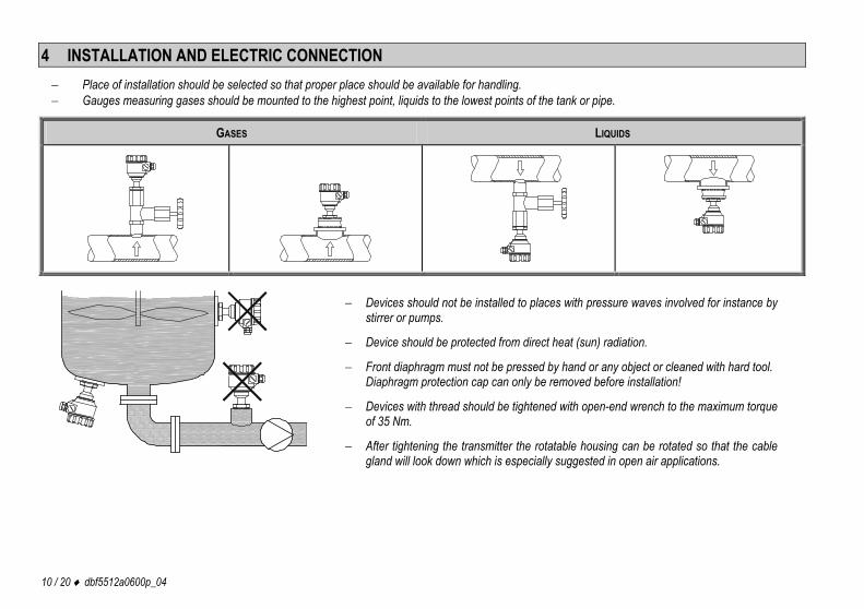
4 INSTALLATION AND ELECTRIC CONNECTION Place of installation should be selected so that proper place should be available for handling. Gauges measuring gases should be mounted to the highest point, liquids to the lowest points of the tank or pipe.
GASES LIQUIDS
Devices should not be installed to places with pressure waves involved for instance by stirrer or pumps.
Device should be protected from direct heat (sun) radiation.
Front diaphragm must not be pressed by hand or any object or cleaned with hard tool.Diaphragm protection cap can only be removed before installation!
Devices with thread should be tightened with open-end wrench to the maximum torque of 35 Nm.
After tightening the transmitter the rotatable housing can be rotated so that the cable gland will look down which is especially suggested in open air applications.
dbf5512a0600p_04 11 / 20
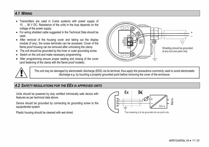
4.1 WIRING Transmitters are used in 2-wire systems with power supply of
10 … 36 V DC. Resistance of the units in the loop depends on the voltage of the power supply.
For wiring shielded cable suggested in the Technical Data should be used.
After removal of the housing cover and taking out the display module (if any), the screw terminals can be accessed. Cover of the flame proof housing can be removed after unhooking the clamp.
The unit should be grounded by the inner or outer grounding screw. Switch on the unit and make necessary programming. After programming ensure proper sealing and closing of the cover
(and fastening of the clamp with the flame proof models).
Shielding should be grounded at any but one point only
–+
! The unit may be damaged by electrostatic discharge (EDS) via its terminal, thus apply the precautions commonly used to avoid electrostatic
discharge e.g. by touching a properly grounded point before removing the cover of the enclosure.
4.2 SAFETY REGULATIONS FOR THE EEX IA APPROVED UNITS
Units should be powered by duly certified intrinsically safe device with features as per technical data above.
Device should be grounded by connecting its grounding screw to the equipotential system
Plastic housing should be cleaned with wet shred.
Main
s+
–
Ex
The screening is to be grounded at one point only
1234
–+
Ex
EEx ia
12 / 20 dbf5512a0600p_04
5 PUTTING INTO OPERATION, PROGRAMMING
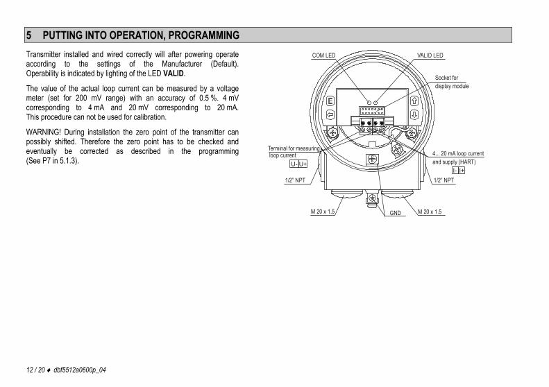
Transmitter installed and wired correctly will after powering operate according to the settings of the Manufacturer (Default). Operability is indicated by lighting of the LED VALID.
The value of the actual loop current can be measured by a voltage meter (set for 200 mV range) with an accuracy of 0.5 %. 4 mV corresponding to 4 mA and 20 mV corresponding to 20 mA. This procedure can not be used for calibration.
WARNING! During installation the zero point of the transmitter can possibly shifted. Therefore the zero point has to be checked and eventually be corrected as described in the programming (See P7 in 5.1.3).
Socket for display module
Terminal for measuring loop current 4... 20 mA loop current
and supply (HART)
GND
1/2” NPT1/2” NPT
M 20 x 1.5M 20 x 1.5
I- I+U- U+
COM LED
dbf5512a0600p_04 13 / 20
5.1 PROGRAMMING Adjustment of the unit to the conditions of the application will be carried out by programming parameters with the aid of the push buttons and following the procedure on the display of the SAP-203 module. The NIVOPRESS is fully operational without the SAP-203 it is only needed for programming and/or displaying measurement values. Manufacturer’s setting is as below: DEFAULT Measurement: pressure Engineering units: bar, for the range of p > 0.6 bar mbar, for the range of p 0.6 bar Current output (4 … 20 mA), Damping: 3 s Error indication: Iout = 3.8 mA
Noise suppression: 50 Hz Density: 1000 kg/m3 Gravitational acceleration: 9.806 m/s2
NIVOPRESS DB- types are incorporating SAP-203 display module but the types DT- are not. If the default is not meeting application requirements or the unit should be used for level measurement the programming i.e. modification of the parameters is needed. This can be performed with the SAP-203 display module. (Obviously for programming of the DT series the plug in of the SAP-203 module is necessary.) The unit will measure during programming in accordance with the parameters set previously. The new, modified parameters will only be effective after returning to the Measurement Mode. If the transmitter is left in Programming Mode by mistake, it will automatically return to Measurement Mode after 3 minutes and will operate with the parameters entered during the last completed programming.
14 / 20 dbf5512a0600p_04
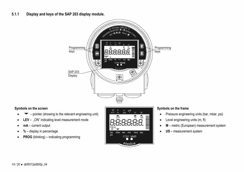
5.1.1 Display and keys of the SAP 203 display module.
SAP-203Display
Programmingkeys
VALID
mbar bar psi
PROG
LEV mA%Programmingkeys
Symbols on the screen – pointer (showing to the relevant engineering unit) LEV – „ON” indicating level measurement mode mA – current output % – display in percentage PROG (blinking) – indicating programming
VALID
LEV mA
sec min dayhourmbarbarpsi
PROG
%
Symbols on the frame Pressure engineering units (bar, mbar, psi) Level engineering units (m, ft) M – metric (European) measurement system US – measurement system
dbf5512a0600p_04 15 / 20
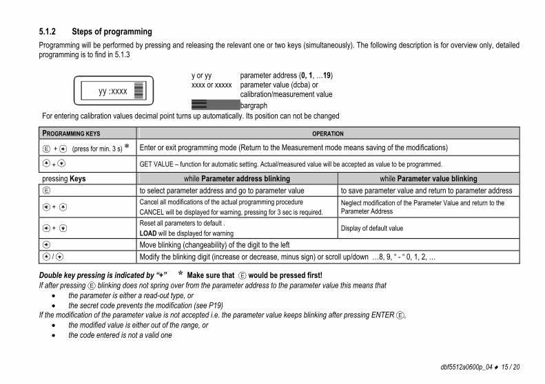
5.1.2 Steps of programming Programming will be performed by pressing and releasing the relevant one or two keys (simultaneously). The following description is for overview only, detailed programming is to find in 5.1.3
yy :xxxx
y or yy parameter address (0, 1, …19) xxxx or xxxxx parameter value (dcba) or calibration/measurement value
bargraph For entering calibration values decimal point turns up automatically. Its position can not be changed
PROGRAMMING KEYS OPERATION
E + (press for min. 3 s) * Enter or exit programming mode (Return to the Measurement mode means saving of the modifications)
+ GET VALUE – function for automatic setting. Actual/measured value will be accepted as value to be programmed.
pressing Keys while Parameter address blinking while Parameter value blinking E to select parameter address and go to parameter value to save parameter value and return to parameter address
+ Cancel all modifications of the actual programming procedure CANCEL will be displayed for warning, pressing for 3 sec is required.
Neglect modification of the Parameter Value and return to the Parameter Address
+ Reset all parameters to default . LOAD will be displayed for warning
Display of default value
Move blinking (changeability) of the digit to the left / Modify the blinking digit (increase or decrease, minus sign) or scroll up/down …8, 9, “ - “ 0, 1, 2, …
Double key pressing is indicated by “+” * Make sure that E would be pressed first! If after pressing E blinking does not spring over from the parameter address to the parameter value this means that
the parameter is either a read-out type, or the secret code prevents the modification (see P19)
If the modification of the parameter value is not accepted i.e. the parameter value keeps blinking after pressing ENTER E , the modified value is either out of the range, or the code entered is not a valid one
16 / 20 dbf5512a0600p_04
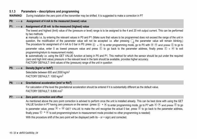
5.1.3 Parameters – descriptions and programming WARNING! During installation the zero point of the transmitter may be shifted. It is suggested to make a correction in P7
P0: - - - a Assignment of 4 mA to the measured (lowest) value
P1: - - - a Assignment of 20 mA to the measured (highest) value The lowest and highest (limit) value of the (pressure or level) range is to be assigned to the 4 and 20 mA output current. This can be performed by two methods a: manually i.e. by entering the relevant values in P0 and P1 (Make sure that values to be programmed does not exceed the range of the unit in question, the modification of the parameter value will not be accepted i.e. after pressing E the parameter value will remain blinking.) The procedure for assignment of 4 mA to 0 bar in P0: press E + to enter programming mode, go to P0 with and press E to go to parameter value, enter 0 as lowest pressure value and press E to go back to the parameter address, finally press E + to exit programming/return to measurement mode). b: automatically i.e. using the GET VALUE function at being in P0 and P1. This method for which the sensor should be put under the required (zero and high limit value) pressure or the relevant level in the tank should be available, provides higher accuracy. FACTORY DEFAULT: limit values of the (pressure) range of the unit in question
P5: - - - a Density [kg/m3 or lb/ft3] Selectable between 600 and 2000 kg/m3 FACTORY DEFAULT: 1000 kg/m3
P6: - - - a Gravitational acceleration [m/s2 or ft/s2] For calculation of the level the gravitational acceleration should be entered if it is substantially different as the default value. FACTORY DEFAULT: 9.806 m/s2
P7: - - - a Zero point correction and offset As mentioned above the zero point correction is advised to perform once the unit is installed already. This can be best done with using the GET VALUE function in P7 having zero pressure on the sensor. (press E + to enter programming mode, go to P7 with and press E to go to parameter value, press + GET VALUE to make the unit recognise the actual 0 bar, press E to go back to the parameter address, finally press E + to exit programming/return to measurement mode provided no other programming is needed) With this procedure shift of the zero point will be displayed (with its – or + sign) and corrected.
dbf5512a0600p_04 17 / 20
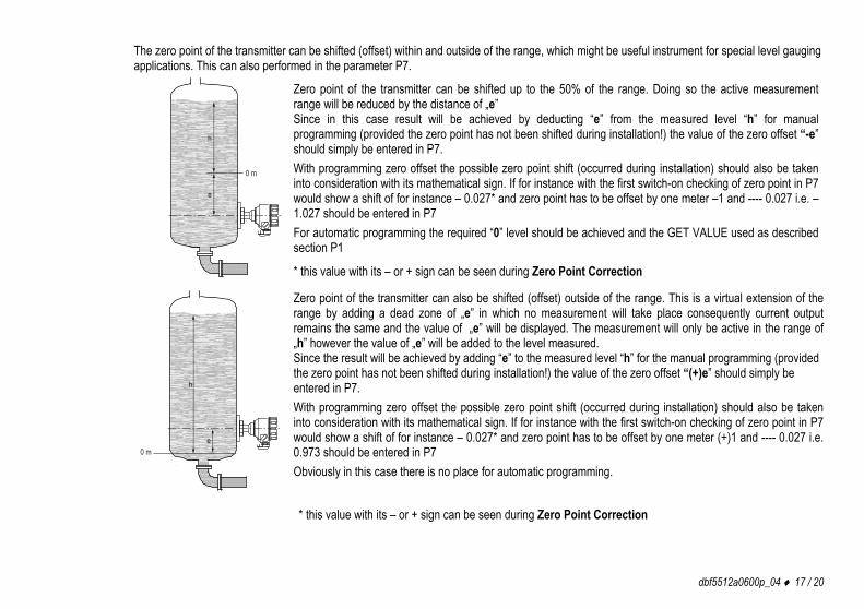
The zero point of the transmitter can be shifted (offset) within and outside of the range, which might be useful instrument for special level gauging applications. This can also performed in the parameter P7.
h
0 m
e
Zero point of the transmitter can be shifted up to the 50% of the range. Doing so the active measurement range will be reduced by the distance of „e” Since in this case result will be achieved by deducting “e” from the measured level “h” for manual programming (provided the zero point has not been shifted during installation!) the value of the zero offset “-e” should simply be entered in P7. With programming zero offset the possible zero point shift (occurred during installation) should also be taken into consideration with its mathematical sign. If for instance with the first switch-on checking of zero point in P7 would show a shift of for instance – 0.027* and zero point has to be offset by one meter –1 and ---- 0.027 i.e. –1.027 should be entered in P7 For automatic programming the required “0” level should be achieved and the GET VALUE used as described section P1
* this value with its – or + sign can be seen during Zero Point Correction
h
0 me
Zero point of the transmitter can also be shifted (offset) outside of the range. This is a virtual extension of the range by adding a dead zone of „e” in which no measurement will take place consequently current output remains the same and the value of „e” will be displayed. The measurement will only be active in the range of „h” however the value of „e” will be added to the level measured. Since the result will be achieved by adding “e” to the measured level “h” for the manual programming (provided the zero point has not been shifted during installation!) the value of the zero offset “(+)e” should simply be entered in P7. With programming zero offset the possible zero point shift (occurred during installation) should also be taken into consideration with its mathematical sign. If for instance with the first switch-on checking of zero point in P7 would show a shift of for instance – 0.027* and zero point has to be offset by one meter (+)1 and ---- 0.027 i.e. 0.973 should be entered in P7 Obviously in this case there is no place for automatic programming.
* this value with its – or + sign can be seen during Zero Point Correction
18 / 20 dbf5512a0600p_04
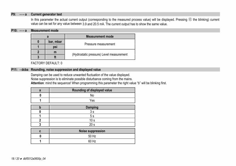
P9: - - - a Current generator test In this parameter the actual current output (corresponding to the measured process value) will be displayed. Pressing E the blinking) current value can be set for any value between 3.9 and 20.5 mA. The current output has to show the same value.
P10: - - - a Measurement mode a Measurement mode
0 bar, mbar 1 psi
Pressure measurement
2 m 3 ft
(Hydrostatic pressure) Level measurement
FACTORY DEFAULT: 0 P11: - dcba Rounding, noise suppression and displayed value
Damping can be used to reduce unwanted fluctuation of the value displayed. Noise suppression is to eliminate possible disturbance coming from the mains. Attention: mind the sequence! When programming this parameter the right value “b” will be blinking first.
a Rounding of displayed value 0 No 1 Yes
b Damping 0 3 s 1 5 s 2 10 s 3 20 s
c Noise suppression 0 50 Hz 1 60 Hz
dbf5512a0600p_04 19 / 20
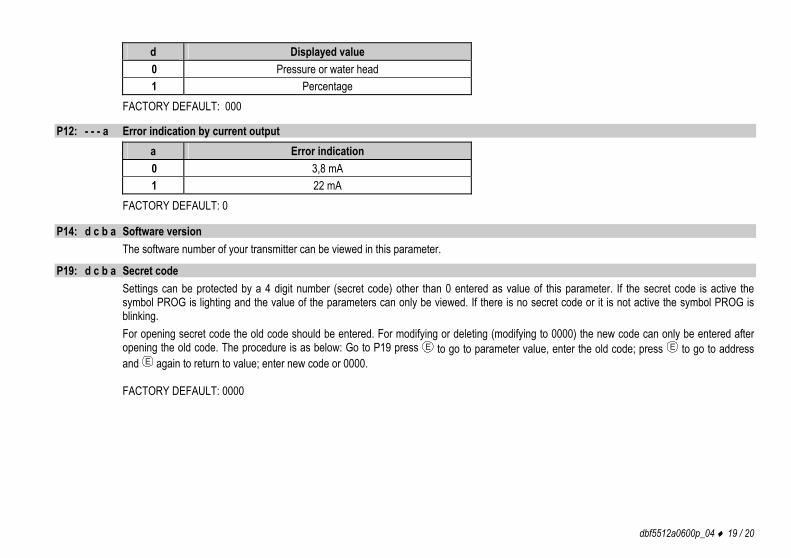
d Displayed value 0 Pressure or water head 1 Percentage
FACTORY DEFAULT: 000
P12: - - - a Error indication by current output a Error indication 0 3,8 mA 1 22 mA
FACTORY DEFAULT: 0
P14: d c b a Software version The software number of your transmitter can be viewed in this parameter.
P19: d c b a Secret code Settings can be protected by a 4 digit number (secret code) other than 0 entered as value of this parameter. If the secret code is active the symbol PROG is lighting and the value of the parameters can only be viewed. If there is no secret code or it is not active the symbol PROG is blinking. For opening secret code the old code should be entered. For modifying or deleting (modifying to 0000) the new code can only be entered after opening the old code. The procedure is as below: Go to P19 press E to go to parameter value, enter the old code; press E to go to address and E again to return to value; enter new code or 0000. FACTORY DEFAULT: 0000
20 / 20 dbf5512a0600p_04
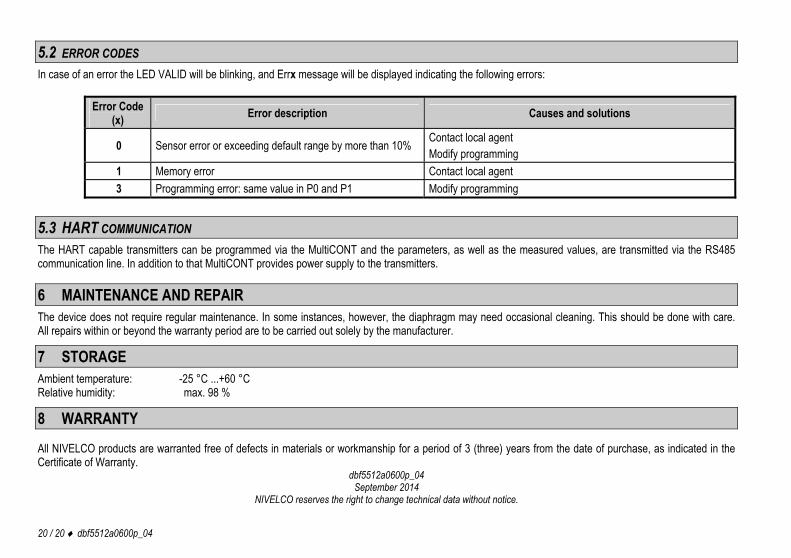
5.2 ERROR CODES In case of an error the LED VALID will be blinking, and Errx message will be displayed indicating the following errors:
Error Code (x) Error description Causes and solutions
0 Sensor error or exceeding default range by more than 10% Contact local agent Modify programming
1 Memory error Contact local agent 3 Programming error: same value in P0 and P1 Modify programming
5.3 HART COMMUNICATION The HART capable transmitters can be programmed via the MultiCONT and the parameters, as well as the measured values, are transmitted via the RS485 communication line. In addition to that MultiCONT provides power supply to the transmitters.
6 MAINTENANCE AND REPAIR The device does not require regular maintenance. In some instances, however, the diaphragm may need occasional cleaning. This should be done with care. All repairs within or beyond the warranty period are to be carried out solely by the manufacturer.
7 STORAGE Ambient temperature: -25 °C ...+60 °C Relative humidity: max. 98 %
8 WARRANTY
All NIVELCO products are warranted free of defects in materials or workmanship for a period of 3 (three) years from the date of purchase, as indicated in the Certificate of Warranty.
dbf5512a0600p_04 September 2014
NIVELCO reserves the right to change technical data without notice.