Embed Size (px)
Citation preview

抽油杆规范
实创翻译
Specification for Sucker Rods, Polished Rods and Liners, Couplings, Sinker Bars, Polished Rod Clamps, Stuffing Boxes, and Pumping Tees
光杆、光杆衬套、接箍、加重杆、光杆卡子、盘根盒
API SPECIFICATION 11B TWENTY-SEVENTH EDITION, MAY 2010
EFFECTIVE DATE: NOVEMBER 1, 2010
Specification for Sucker Rods, Polished Rods and Liners, Couplings, Sinker Bars, Polished Rod Clamps, Stuffing Boxes, and Pumping Tees
Upstream Segment
API SPECIFICATION 11B TWENTY-SEVENTH EDITION, MAY 2010
EFFECTIVE DATE: NOVEMBER 1, 2010

Special Notes
API publications necessarily address problems of a general nature. With respect to particular circumstances, local, state, and federal laws and regulations should be reviewed.
Neither API nor any of API's employees, subcontractors, consultants, committees, or other assignees make any warranty or representation, either express or implied, with respect to the accuracy, completeness, or usefulness of the information contained herein, or assume any liability or responsibility for any use, or the results of such use, of any information or process disclosed in this publication. Neither API nor any of API's employees, subcontractors, consultants, or other assignees represent that use of this publication would not infringe upon privately owned rights.
API publications may be used by anyone desiring to do so. Every effort has been made by the Institute to assure the accuracy and reliability of the data contained in them; however, the Institute makes no representation, warranty, or guarantee in connection with this publication and hereby expressly disclaims any liability or responsibility for loss or damage resulting from its use or for the violation of any authorities having jurisdiction with which this publication may conflict.
API publications are published to facilitate the broad availability of proven, sound engineering and operating practices. These publications are not intended to obviate the need for applying sound engineering judgment regarding when and where these publications should be utilized. The formulation and publication of API publications is not intended in any way to inhibit anyone from using any other practices.
Any manufacturer marking equipment or materials in conformance with the marking requirements of an API standard is solely responsible for complying with all the applicable requirements of that standard. API does not represent, warrant, or guarantee that such products do in fact conform to the applicable API standard.
All rights reserved. No part of this work may be reproduced, translated, stored in a retrieval system, or transmitted by any means, electronic, mechanical, photocopying, recording, or otherwise, without prior written permission from the publisher. Contact the
Publisher, API Publishing Services, 1220 L Street, NW, Washington, DC 20005.
Copyright © 2010 American Petroleum Institute
Foreword
Nothing contained in any API publication is to be construed as granting any right, by implication or otherwise, for the manufacture, sale, or use of any method, apparatus, or product covered by letters patent. Neither should anything contained in the publication be construed as insuring anyone against liability for infringement of letters patent.
Shall: As used in a standard, “shall” denotes a minimum requirement in order to conform to the specification.
Should: As used in a standard, “should” denotes a recommendation or that which is advised but not required in order to conform to the specification.
This document was produced under API standardization procedures that ensure appropriate notification and participation in the developmental process and is designated as an API standard. Questions concerning the interpretation of the content of this publication or comments and questions concerning the procedures under which this publication was developed should be directed in writing to the Director of Standards, American Petroleum Institute, 1220 L Street, NW, Washington, DC 20005. Requests for permission to reproduce or translate all or any part of the material published herein should also be addressed to the director.
Generally, API standards are reviewed and revised, reaffirmed, or withdrawn at least every five years. A one-time extension of up to two years may be added to this review cycle. Status of the publication can be ascertained from the API Standards Department, telephone (202) 682-8000. A catalog of API publications and materials is published annually by API, 1220 L Street, NW, Washington, DC 20005.
Suggested revisions are invited and should be submitted to the Standards Department, API, 1220 L Street, NW, Washington, DC 20005, [email protected].
iii
Contents
Page
目录
v
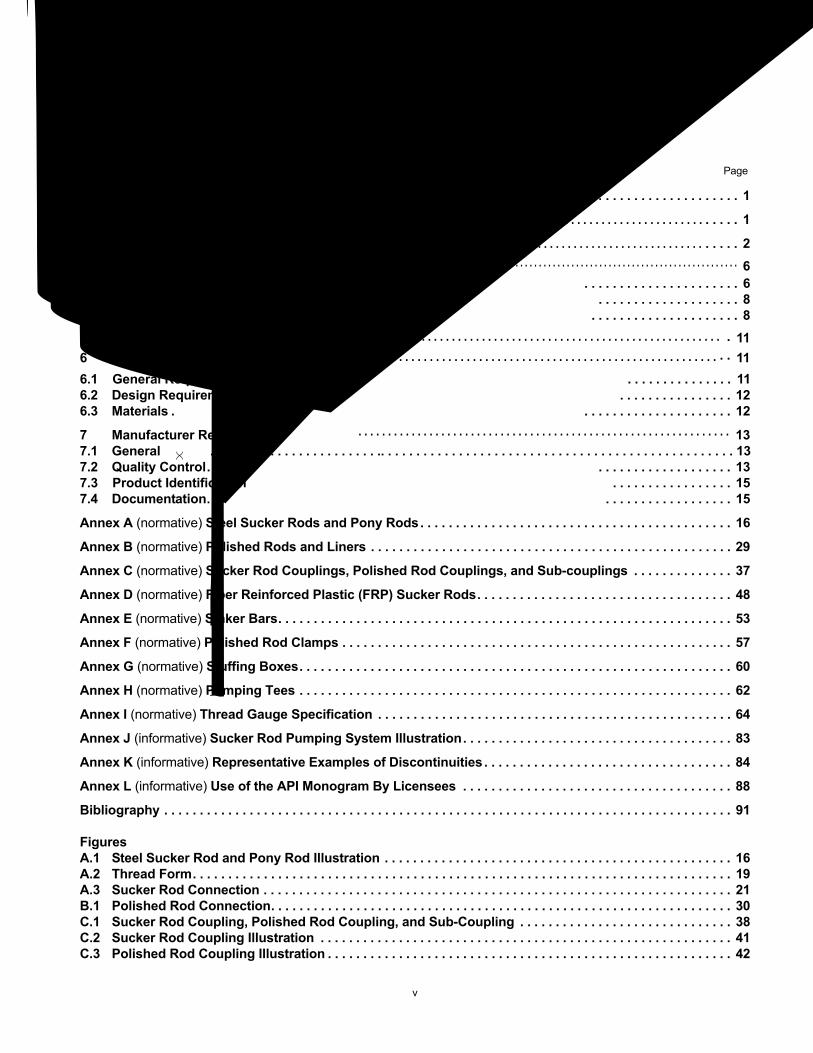
1 Scope . . . . . . . . . . . . . . . . . . . . . . . . . . . . . . . . . . . . . . . . . . . . . . . . . . . . . . . . . . . . . . . . . . . . . . . . . . . . . . . . . . 1
2 Normative References . . . . . . . . . . . . . . . . . . . . . . . . . . . . . . . . . . . . . . . . . . . . . . . . . . . . . . . . . . . . . . . . . . . . . 1
3 Terms and Definitions . . . . . . . . . . . . . . . . . . . . . . . . . . . . . . . . . . . . . . . . . . . . . . . . . . . . . . . . . . . . . . . . . . . . . 2
4 Symbols, Abbreviations and Gauge List . . . . . . . . . . . . . . . . . . . . . . . . . . . . . . . . . . . . . . . . . . . . . . . . . . . . . 64.1 Symbols . . . . . . . . . . . . . . . . . . . . . . 64.2 Abbreviations. . . . . . . . . . . . . . . . . . . . . 84.3 Gauge List . . . . . . . . . . . . . . . . . . . . . 8
5 Functional Requirements . . . . . . . . . . . . . . . . . . . . . . . . . . . . . . . . . . . . . . . . . . . . . . . . . . . . . . . . . . . . . . . . . 116 Technical Requirements . . . . . . . . . . . . . . . . . . . . . . . . . . . . . . . . . . . . . . . . . . . . . . . . . . . . . . . . . . . . . . . . . . 116.1 General Requirements . . . . . . . . . . . . . . . 116.2 Design Requirements . . . . . . . . . . . . . . . . 126.3 Materials . . . . . . . . . . . . . . . . . . . . . . 12
7 Manufacturer Requirements . . . . . . . . . . . . . . . . . . . . . . . . . . . . . . . . . . . . . . . . . . . . . . . . . . . . . . . . . . . . . . . 137.1 General . . .. . . . . . . . . . . . . . . . . . . . . .. . . . . . . . . . . . . . . . . . . . . . . . . . . . . . . . . . . . . . . . . . . . . . . . . . 137.2 Quality Control. . . . . . . . . . . . . . . . . . . . 137.3 Product Identification . . . . . . . . . . . . . . . . . 157.4 Documentation. . . . . . . . . . . . . . . . . . . 15
Annex A (normative) Steel Sucker Rods and Pony Rods. . . . . . . . . . . . . . . . . . . . . . . . . . . . . . . . . . . . . . . . . . . . 16
Annex B (normative) Polished Rods and Liners . . . . . . . . . . . . . . . . . . . . . . . . . . . . . . . . . . . . . . . . . . . . . . . . . . . 29
Annex C (normative) Sucker Rod Couplings, Polished Rod Couplings, and Sub-couplings . . . . . . . . . . . . . . 37
Annex D (normative) Fiber Reinforced Plastic (FRP) Sucker Rods. . . . . . . . . . . . . . . . . . . . . . . . . . . . . . . . . . . . 48
Annex E (normative) Sinker Bars. . . . . . . . . . . . . . . . . . . . . . . . . . . . . . . . . . . . . . . . . . . . . . . . . . . . . . . . . . . . . . . . 53
Annex F (normative) Polished Rod Clamps . . . . . . . . . . . . . . . . . . . . . . . . . . . . . . . . . . . . . . . . . . . . . . . . . . . . . . . 57
Annex G (normative) Stuffing Boxes. . . . . . . . . . . . . . . . . . . . . . . . . . . . . . . . . . . . . . . . . . . . . . . . . . . . . . . . . . . . . 60
Annex H (normative) Pumping Tees . . . . . . . . . . . . . . . . . . . . . . . . . . . . . . . . . . . . . . . . . . . . . . . . . . . . . . . . . . . . . 62
Annex I (normative) Thread Gauge Specification . . . . . . . . . . . . . . . . . . . . . . . . . . . . . . . . . . . . . . . . . . . . . . . . . . 64
Annex J (informative) Sucker Rod Pumping System Illustration. . . . . . . . . . . . . . . . . . . . . . . . . . . . . . . . . . . . . . 83
Annex K (informative) Representative Examples of Discontinuities . . . . . . . . . . . . . . . . . . . . . . . . . . . . . . . . . . . 84
Annex L (informative) Use of the API Monogram By Licensees . . . . . . . . . . . . . . . . . . . . . . . . . . . . . . . . . . . . . . 88
Bibliography . . . . . . . . . . . . . . . . . . . . . . . . . . . . . . . . . . . . . . . . . . . . . . . . . . . . . . . . . . . . . . . . . . . . . . . . . . . . . . . . 91
FiguresA.1 Steel Sucker Rod and Pony Rod Illustration . . . . . . . . . . . . . . . . . . . . . . . . . . . . . . . . . . . . . . . . . . . . . . . . . 16A.2 Thread Form. . . . . . . . . . . . . . . . . . . . . . . . . . . . . . . . . . . . . . . . . . . . . . . . . . . . . . . . . . . . . . . . . . . . . . . . . . . . 19A.3 Sucker Rod Connection . . . . . . . . . . . . . . . . . . . . . . . . . . . . . . . . . . . . . . . . . . . . . . . . . . . . . . . . . . . . . . . . . . 21B.1 Polished Rod Connection. . . . . . . . . . . . . . . . . . . . . . . . . . . . . . . . . . . . . . . . . . . . . . . . . . . . . . . . . . . . . . . . . 30C.1 Sucker Rod Coupling, Polished Rod Coupling, and Sub-Coupling . . . . . . . . . . . . . . . . . . . . . . . . . . . . . . 38C.2 Sucker Rod Coupling Illustration . . . . . . . . . . . . . . . . . . . . . . . . . . . . . . . . . . . . . . . . . . . . . . . . . . . . . . . . . . 41C.3 Polished Rod Coupling Illustration . . . . . . . . . . . . . . . . . . . . . . . . . . . . . . . . . . . . . . . . . . . . . . . . . . . . . . . . . 42
范围
参考标准
条款和定义
符号、缩写和对照表
功能要求
技术要求
制造要求
总要求设计要求材料
总则质量控制
生产标识
文档
缩写
对照表
符号

Contents
Page
C.4 Rockwell A Hardness Determination of Base Metal . . . . . . . . . . . . . . . . . . . . . . . . . . . . . . . . . . . . . . . . . . . 43C.5 Vickers Micro-hardness Determination of Spray Metal Coating . . . . . . . . . . . . . . . . . . . . . . . . . . . . . . . . . 44D.1 General Dimensions for FRP Sucker Rod Pin Ends . . . . . . . . . . . . . . . . . . . . . . . . . . . . . . . . . . . . . . . . . . . 48E.1 Sinker Bar Nomenclature . . . . . . . . . . . . . . . . . . . . . . . . . . . . . . . . . . . . . . . . . . . . . . . . . . . . . . . . . . . . . . . . . 53I.1 Go Pin-thread Gauges (For Gauging Sucker Rod Pin Connections) . . . . . . . . . . . . . . . . . . . . . . . . . . . . . 69I.2 No-go Pin-thread Gauges (For Gauging Sucker Rod and Polished Rod Pin Connections). . . . . . . . . . . 70I.3 Go Box-Thread Gauges (For Gauging Box Connections) . . . . . . . . . . . . . . . . . . . . . . . . . . . . . . . . . . . . . . 72I.4 Box-cone Gauges (For Gauging Box Connections) . . . . . . . . . . . . . . . . . . . . . . . . . . . . . . . . . . . . . . . . . . . 74I.5 No-go Box-thread Gauges (For Gauging Box Connections) . . . . . . . . . . . . . . . . . . . . . . . . . . . . . . . . . . . . 75I.6 Go Pin-thread Gauges (For Gauging Polished Rod Pin Connections) . . . . . . . . . . . . . . . . . . . . . . . . . . . . 77I.7 Pin-cone Gauges (For Gauging Polished Rod Pin Connections) . . . . . . . . . . . . . . . . . . . . . . . . . . . . . . . . 79
Tables A.1 Dimensions and Tolerances for Steel Sucker Rods and Steel Pony Rods. . . . . . . . . . . . . . . . . . . . . . . . . 17A.2 Specified Dimensions for Pin End Threads . . . . . . . . . . . . . . . . . . . . . . . . . . . . . . . . . . . . . . . . . . . . . . . . . . 18A.3 Thread Form Dimensional Relationships . . . . . . . . . . . . . . . . . . . . . . . . . . . . . . . . . . . . . . . . . . . . . . . . . . . . 20A.4 Chemical Composition of Steel Sucker Rods . . . . . . . . . . . . . . . . . . . . . . . . . . . . . . . . . . . . . . . . . . . . . . . . 21A.5 Mechanical Properties of Steel Sucker Rods and Pony Rods . . . . . . . . . . . . . . . . . . . . . . . . . . . . . . . . . . . 22A.6 Dimensional Inspection of Steel Sucker Rods, Steel Pony Rods, and Sinker Bars . . . . . . . . . . . . . . . . . 23A.7 Color Marking Requirements . . . . . . . . . . . . . . . . . . . . . . . . . . . . . . . . . . . . . . . . . . . . . . . . . . . . . . . . . . . . . . 27B.1 General Dimensions and Tolerances for Polished Rod Liners . . . . . . . . . . . . . . . . . . . . . . . . . . . . . . . . . . 30B.2 General Dimensions for Polished Rod Liners . . . . . . . . . . . . . . . . . . . . . . . . . . . . . . . . . . . . . . . . . . . . . . . . 31B.3 Polished Rod Pin Connection Dimensional Requirements . . . . . . . . . . . . . . . . . . . . . . . . . . . . . . . . . . . . . 32B.4 Dimensional Inspection of Polished Rods . . . . . . . . . . . . . . . . . . . . . . . . . . . . . . . . . . . . . . . . . . . . . . . . . . . 34B.5 Sprayed Metal Chemical Composition for Polished Rods and Polished Rod Liners . . . . . . . . . . . . . . . . 35C.1 External Dimensions and Tolerances for Sucker Rod Couplings, Polished Rod
Couplings, and Sub-couplings . . . . . . . . . . . . . . . . . . . . . . . . . . . . . . . . . . . . . . . . . . . . . . . . . . . . . . . . . . . . 39C.2 Dimensional Requirements for Polished Rod and Sucker Rod Box Connections . . . . . . . . . . . . . . . . . . 40C.3 Sprayed Metal Coating Chemical Composition . . . . . . . . . . . . . . . . . . . . . . . . . . . . . . . . . . . . . . . . . . . . . . . 44C.4 Dimensional Inspection of Sucker Rod Couplings, Polished Rod Couplings, and Sub-couplings . . . . 46D.1 General Dimensions and Tolerances for FRP Sucker Rods and Pony Rods. . . . . . . . . . . . . . . . . . . . . . . 49D.2 FRP Sucker Rod End Fitting Grades and Mechanical Properties . . . . . . . . . . . . . . . . . . . . . . . . . . . . . . . . 50E.1 General Dimensions and Tolerances for Sinker Bars. . . . . . . . . . . . . . . . . . . . . . . . . . . . . . . . . . . . . . . . . . 54E.2 Mechanical Strength Properties . . . . . . . . . . . . . . . . . . . . . . . . . . . . . . . . . . . . . . . . . . . . . . . . . . . . . . . . . . . 55I.1 P7 Go Pin-thread Truncated Setting Plug Gauge, P8 Go Pin-thread Ring Gauge. . . . . . . . . . . . . . . . . . . 68I.2 P5 No-go Pin-thread Truncated Setting Plug Gauge, P6 No-go Pin-thread Ring Gauge . . . . . . . . . . . . . 70I.3 B1 Go Box-thread Ring Gauge (Checking Ring), B2 Go Box-thread Plug Gauge. . . . . . . . . . . . . . . . . . . 71I.4 B3 Box-cone Ring Gauge (Fitting Ring), B4 Box-cone Plug Gauge . . . . . . . . . . . . . . . . . . . . . . . . . . . . . . 73I.5 B5 No-go Box-thread Ring Gauge (Checking Ring), B6 No-go Box-thread Plug Gauge . . . . . . . . . . . . . 75I.6 P1 Go Pin-thread Truncated Setting plug Gauge, P2 Go Pin-thread Ring Gauge . . . . . . . . . . . . . . . . . . . 76I.7 P3 Go Pin-cone Plug Gauge (Fitting Plug), P4 Pin-cone Ring Gauge. . . . . . . . . . . . . . . . . . . . . . . . . . . . . 78I.8 Tolerances for Reference Master Gauges . . . . . . . . . . . . . . . . . . . . . . . . . . . . . . . . . . . . . . . . . . . . . . . . . . . 80I.9 Allowable Axial Variation of Shoulder Face . . . . . . . . . . . . . . . . . . . . . . . . . . . . . . . . . . . . . . . . . . . . . . . . . . 80
Introduction
This specification has been developed by users, purchasers, suppliers and manufacturers of sucker rods, polished rods and liners, coupings, sinker bars, polished rod clamps, stuffing boxes, and pumping tees intended for use in the petroleum and natural gas industry worldwide. This specification is intended to give requirements and information to all parties in the design, manufacture and selection of sucker rods, polished rods and liners, coupings, sinker bars, polished rod clamps, stuffing boxes, and pumping tees. Furthermore, this specification addresses the minimum requirements with which the manufacturer is to claim conformity with this specification.
Included within this specification are normative annexes specifying equipment requirements and an informative annex providing a system illustration.
Attention is brought to users of this specification that requirements above those outlined in this specification can be required for individual applications. This specification is not intended to inhibit a manufacturer from offering, or the user or purchaser from accepting alternative equipment or other engineering solutions. This can be particularly applicable where there is innovative or developing technology. Where an alternative is offered, it is the responsibility of the manufacturer to identify any variations from this specification.
In this specification, quantities expressed in United States Customary (USC) units are also, where practical, expressed in International System (SI) units, either in parentheses in the text or on separate data sheets. USC units shall be the controlling units, SI units are included as a convenience for the user of this specification.
vi
Specification for Sucker Rods, Polished Rods and Liners, Couplings, Sinker Bars, Polished Rod Clamps, Stuffing Boxes, and Pumping Tees
1 Scope
This specification provides the requirements and guidelines for the design of steel sucker rods and pony rods, polished rods, polished rod liners, couplings and sub-couplings, fiber reinforced plastic (FRP) sucker rods, sinker bars, polished rod clamps, stuffing boxes, and pumping tees as defined herein for use in the sucker rod lift method for the petroleum and natural gas industry. Annex A through Annex H provide the requirements for specific products. Annex I includes the requirements for thread gauges, Annex J illustrates the components of a sucker rod lift system, and Annex K shows examples of sucker rod discontinuities.
This specification does not cover sucker rod guides, sucker rod rotators, shear tools, on-off tools, stabilizer bars, sealing elements used in stuffing boxes, or interface connections for stuffing boxes and pumping tees. Also, installation, operation and maintenance of these products are not included in this specification.
2 Normative References
The following referenced documents are indispensable for the application of this document. For dated references, only the edition cited applies. For undated references, the latest edition of the referenced document (including any amendments) applies.
API Specification Q1/ISO 29001:2007, Specification for Quality Programs for the Petroleum and Natural Gas Industry
API Specification 5B, Threading, Gauging and Thread Inspection of Casing, Tubing and Line Pipe Threads
ANSI/ASME B1.1 1, Unified Inch Screw Threads, (UN and UNR Thread Form)
ANSI/ASQ Z1.4 2Sampling Procedures and Tables for Inspection by Attributes
ASTM A370 3, Standard Test Methods and Definitions for Mechanical Testing of Steel Products
ASTM A395, Standard Specification for Ferritic Ductile Iron Pressure-Retaining Castings for Use at Elevated Temperatures
ASTM A536, Standard Specification for Ductile Iron Castings
ASTM A751, Standard Test Methods, Practices, and Terminology for Chemical Analysis of Steel Products
ASTM D2583, Test Method for Indention Hardness of Rigid Plastics by Means of a Barcol Impressor
ASTM D2584, Test Method for Ignition Loss of Cured Reinforced Resins
ASTM D4475, Test Method for Apparent Horizontal Shear Strength of Pultruded Reinforced Plastic Rods by the Short-Beam Method
ASTM E18, Standard Test Methods for Rockwell Hardness and Rockwell Superficial Hardness of Metallic Materials
ASTM E384, Standard Test Method for Microindentation Hardness of Materials
1 ASME International, 3 Park Avenue, New York, New York 10016-5990, www.asme.org.2 American Society for Quality, P.O. Box 300, Milwaukee, Wisconsin 53201-3005, www.asq.org.3 ASTM International, 100 Barr Harbor Drive, West Conshohocken, Pennsylvania 19428, www.astm.org.
1

2 API SPECIFICATION 11B
ISO 2859-1 4, Sampling procedures for inspection by attributes—Part 1: Sampling schemes indexed by acceptance quality limit (AQL) for lot-by-lot inspection
ISO 6508-1, Metallic materials—Rockwell hardness test—Part 1: Test method (scales A, B, C, D, E, F, G, H, K, N, T)
ISO 6892, Metallic materials—Tensile testing at ambient temperature
ISO 15156-1, Petroleum and natural gas industries—Materials for use in H2S-containing environments in oil and gas production—Part 1: General principles for selection of cracking-resistant materials
ISO 15156-2, Petroleum and natural gas industries—Materials for use in H2S-containing environments in oil and gas production—Part 2: Cracking-resistant carbon and low alloy steels, and the use of cast irons
ISO 15156-3, Petroleum and natural gas industries—Materials for use in H2S-containing environments in oil and gas production—Part 3: Cracking-resistant CRAs (corrosion-resistant alloys) and other alloys
NACE No. 1/SSPC-SP 5 5, White Metal Blast Cleaning
ANSI/NCSL Z540-1 6, Calibration Laboratories and Measuring and Test Equipment—General Requirements
3 Terms and Definitions
For the purpose of this document the following terms and definitions apply. For quality system related terms used in this Specification and not defined below, see API Q1.
3.1batch lots processingMaterial processed in a machine in defined quantities or volumes.
3.2bodyThe length of the rod located between the upset transitions, see Figure A.1.
3.3continuous processing Material flowing steadily through the processing equipment in an undefined quantity or volume.
3.4 couplings Internally threaded components used to connect sucker rods, sinker bars, pony rods, or polished rods from the surface to the subsurface pump where both threads are of the same size and type.
3.5dentLocal change in surface contour caused by mechanical impact, but not accompanied by a loss of metal.
4 International Organization for Standardization, 1, ch. de la Voie-Creuse, Case postale 56, CH-1211, Geneva 20, Switzerland, www.iso.org.
5 NACE International, 1440 South Creek Drive, Houston, Texas, 77084-4906, www.nace.org.6 NCSL International, 2995 Wilderness Place, Suite 107, Boulder, Colorado 80301-5404, www.ncsli.org.
SPECIFICATION FOR SUCKER RODS, POLISHED RODS AND LINERS, COUPLINGS, SINKER BARS, POLISHED ROD CLAMPS, STUFFING BOXES, AND PUMPING TEES 3
3.6discontinuityInterruption in the normal physical structure or configuration such as cracks, laps, seams, pits, and laminations.
3.7end shear crackMill shear discontinuity, which shows as a crack across the pin end face.
3.8fiber reinforced plastic (FRP) sucker rodSucker rod typically manufactured in three pieces and assembled by a process that provides connection of two metal end fittings connected to a non-metallic fiber reinforced plastic rod.
3.9forging lapDiscontinuity produced when two metal surfaces fold against each other without metallurgical bonding.
3.10forging overfillExcessive metal stocking of the forging die resulting in a forging lap.
3.11independent calibration agency Organization providing calibration services that is independent of the manufacturer.
3.12kink Short, tight bend.
3.13longitudinalDirection along the long axis of the rod.
3.14longitudinal discontinuityDiscontinuity where the orientation of the long axis of the discontinuity is within plus or minus 60 ° from the longitudinal direction and is longer in the longitudinal direction than in the transverse direction.
3.15micro-crackCrack undetectable by unaided visual inspection.
3.16nickLocal change in surface contour accompanied by a loss in metal caused by mechanical impact.
3.17on-off toolsTwo-piece, reusable tool that provides a means of remotely connecting and disconnecting the sucker rods at or above the sucker rod pump.
3.18pitSmall, regular or irregular crater where the major (longest) diameter is not more than twice the minor (shortest) diameter.
4 API SPECIFICATION 11B
3.19polished rodRod of standard length and diameter with a surface finish designed to facilitate a pressure seal in a stuffing box and to provide a mechanical link between equipment inside and outside the well.
3.20polished rod clampDevice attached to the polished rod, which in conjunction with the pumping unit carrier bar secures a polished rod to the surface pumping unit.
3.21polished rod liner A hard, sprayed metal, thin walled tube that is installed over and seals against the polished rod and stuffing box internal seals.
3.22pony rodSucker rod of reduced length used to place the pump at the desired depth in the well.
3.23pull backDiscontinuity in the sprayed metal coating where the coating does not extend to its intended surface coverage.
3.24pumping teeTubing fitting assembled to the top of a pumping well and below a stuffing box, designed to discharge production fluids through a side opening connected to a flow line.
3.25qualified personPersonnel with characteristics or abilities, gained through training and/or experience as measured against established requirements, standards or tests, that enable the individual to perform a required function.
3.26reference master gaugeGauge which has been certified by an independent calibration agency and is used for verification and calibration of working gauges.
3.27rod guidesMetallic or polymeric materials attached to the sucker rod string to centralize the sucker rods and reduce sucker rod and tubing wear and/or reduce paraffin build-up.
3.28rolled-in-scaleSurface discontinuity caused by scale (metal oxide) formed during a previous heating which has not been removed prior to bar rolling or upset forging.
3.29rolling lapLongitudinal surface discontinuity that can have the appearance of a seam, caused during rolling, fins, or sharp corners being folded over and then rolled into the bar surface without metallurgical bonding.

SPECIFICATION FOR SUCKER RODS, POLISHED RODS AND LINERS, COUPLINGS, SINKER BARS, POLISHED ROD CLAMPS, STUFFING BOXES, AND PUMPING TEES 5
3.30rolling overfillRaised ridges formed during bar rolling.
3.31scab (sliver) Loose or torn segment of material or debris rolled into the surface of the bar.
3.32seamLongitudinal discontinuity which can be closed or open, but without metallurgical bonding, which can have the appearance of a straight line, scratch, or small longitudinal separation.
3.33shake testPerceptible movement of the gauge when rocked back and forth, see Annex I.6.
3.34shear toolsStraight line pull safety joint release that provides a means of disconnecting the sucker rod string from the pump below the tool.
3.35stabilizer barsSpecial pony rod with rod guides, normally used above the pump or between sinker bars.
3.36sinker barA steel rod of a specified length, normally in a larger diameter than the sucker rods, provided in standard sizes with externally threaded ends provided to add weight and stability to the sucker rod string.
3.37stuffing boxDevice with accessory sealing elements used in conjunction with the polished rod to facilitate sealing of the well bore.
3.38sub-couplingsInternally threaded components with polished rod threads used to connect polished rods, pony rods, sucker rods, or sinker bars, to the subsurface pump, or to each other, where both threads are not of the same size.
3.39sucker rodSteel or fiber reinforced plastic rod of standard length and diameter with externally threaded ends, typically used for transmitting mechanical power to the subsurface pump.
3.40sucker rod bodyBody of the sucker rod or pony rod between the upset tapers.
3.41sucker rod liftArtificial lift method that lifts fluids (oil, water, condensate and/or gas) from a well with a sucker rod string and sucker rod pump operating in a linear reciprocating mode.
6 API SPECIFICATION 11B
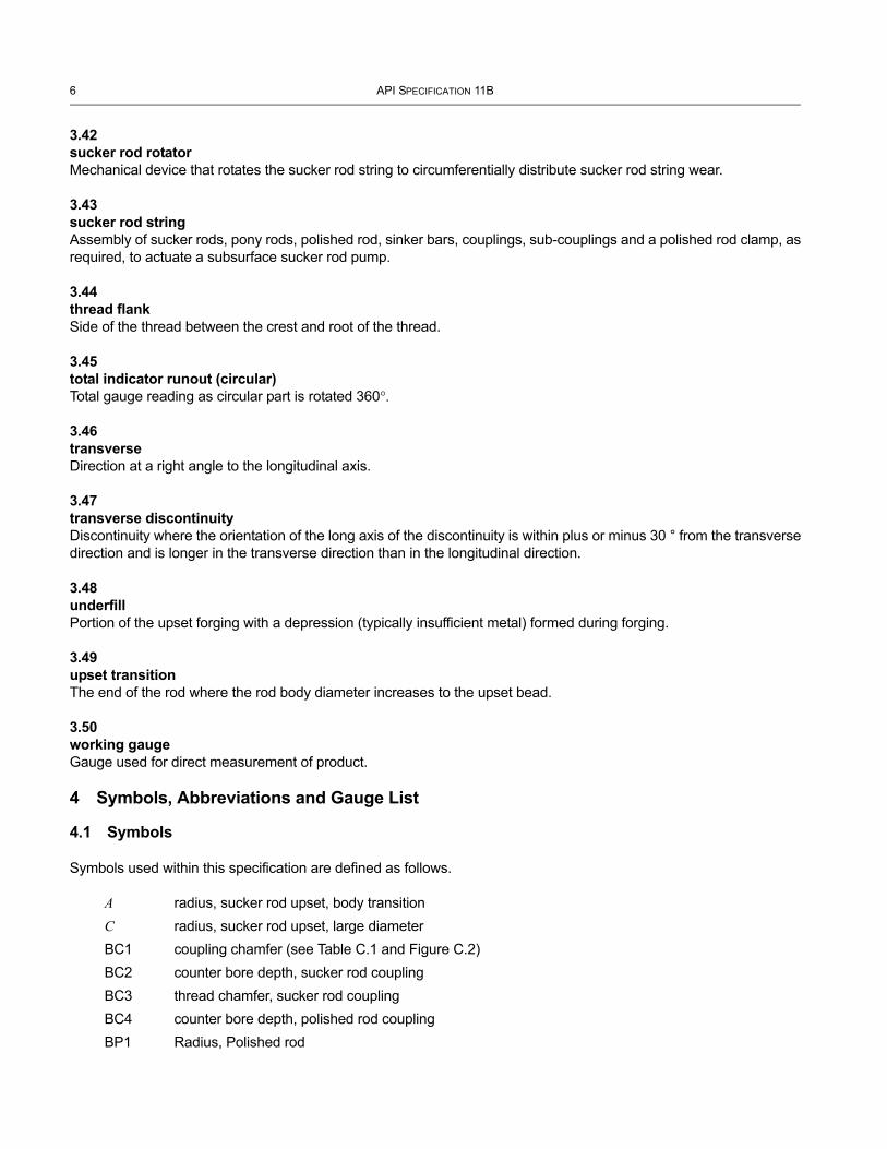
3.42sucker rod rotatorMechanical device that rotates the sucker rod string to circumferentially distribute sucker rod string wear.
3.43sucker rod stringAssembly of sucker rods, pony rods, polished rod, sinker bars, couplings, sub-couplings and a polished rod clamp, as required, to actuate a subsurface sucker rod pump.
3.44thread flankSide of the thread between the crest and root of the thread.
3.45total indicator runout (circular)Total gauge reading as circular part is rotated 360°.
3.46transverseDirection at a right angle to the longitudinal axis.
3.47transverse discontinuityDiscontinuity where the orientation of the long axis of the discontinuity is within plus or minus 30 ° from the transverse direction and is longer in the transverse direction than in the longitudinal direction.
3.48underfillPortion of the upset forging with a depression (typically insufficient metal) formed during forging.
3.49upset transitionThe end of the rod where the rod body diameter increases to the upset bead.
3.50working gaugeGauge used for direct measurement of product.
4 Symbols, Abbreviations and Gauge List
4.1 Symbols
Symbols used within this specification are defined as follows.
A radius, sucker rod upset, body transition C radius, sucker rod upset, large diameterBC1 coupling chamfer (see Table C.1 and Figure C.2)BC2 counter bore depth, sucker rod couplingBC3 thread chamfer, sucker rod couplingBC4 counter bore depth, polished rod couplingBP1 Radius, Polished rod
SPECIFICATION FOR SUCKER RODS, POLISHED RODS AND LINERS, COUPLINGS, SINKER BARS, POLISHED ROD CLAMPS, STUFFING BOXES, AND PUMPING TEES 7
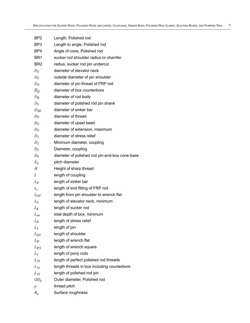
BP2 Length, Polished rodBP3 Length to angle, Polished rodBP4 Angle of cone, Polished rodBR1 sucker rod shoulder radius or chamferBR2 radius, sucker rod pin undercutDE diameter of elevator neckDF outside diameter of pin shoulderDN diameter of pin thread of FRP rod DQ diameter of box counterboreDR diameter of rod bodyDS diameter of polished rod pin shankDSB diameter of sinker barDT diameter of threadDU diameter of upset beadDX diameter of extension, maximumD1 diameter of stress relief D2 Minimum diameter, couplingD3 Diameter, couplingD4 diameter of polished rod pin-and-box cone baseES pitch diameterH Height of sharp threadL length of couplingLB length of sinker barLc length of end fitting of FRP rod LDF length from pin shoulder to wrench flatLE length of elevator neck, minimumLK length of sucker rodLnb total depth of box, minimumLR length of stress reliefLS length of pinLSH length of shoulderLW length of wrench flatLWS length of wrench squareLY length of pony rodsL2S length of perfect polished rod threadsL3n length threads in box including counterboreL3S length of polished rod pinODp Outer diameter, Polished rodp thread pitchRa Surface roughness
8 API SPECIFICATION 11B
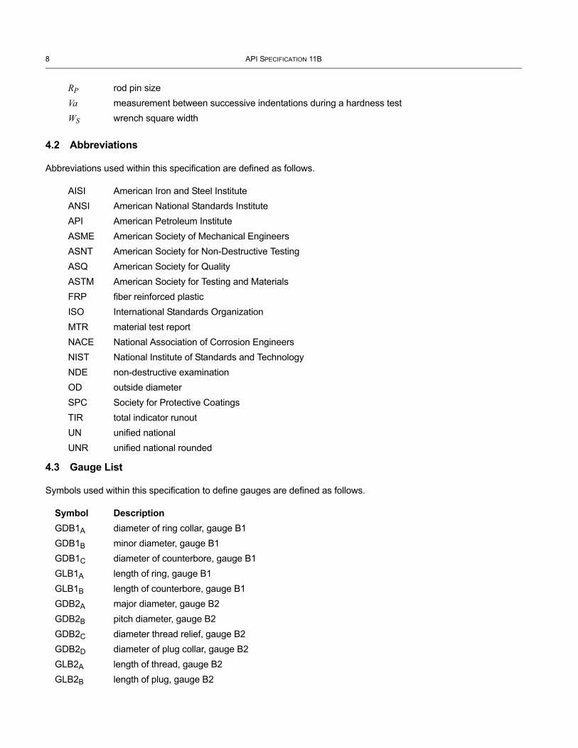
RP rod pin sizeVa measurement between successive indentations during a hardness testWS wrench square width
4.2 Abbreviations
Abbreviations used within this specification are defined as follows.
AISI American Iron and Steel InstituteANSI American National Standards InstituteAPI American Petroleum Institute ASME American Society of Mechanical EngineersASNT American Society for Non-Destructive TestingASQ American Society for QualityASTM American Society for Testing and MaterialsFRP fiber reinforced plasticISO International Standards Organization MTR material test reportNACE National Association of Corrosion EngineersNIST National Institute of Standards and TechnologyNDE non-destructive examinationOD outside diameterSPC Society for Protective CoatingsTIR total indicator runoutUN unified nationalUNR unified national rounded
4.3 Gauge List
Symbols used within this specification to define gauges are defined as follows.
Symbol DescriptionGDB1A diameter of ring collar, gauge B1GDB1B minor diameter, gauge B1GDB1C diameter of counterbore, gauge B1GLB1A length of ring, gauge B1GLB1B length of counterbore, gauge B1GDB2A major diameter, gauge B2GDB2B pitch diameter, gauge B2GDB2C diameter thread relief, gauge B2GDB2D diameter of plug collar, gauge B2GLB2A length of thread, gauge B2GLB2B length of plug, gauge B2
SPECIFICATION FOR SUCKER RODS, POLISHED RODS AND LINERS, COUPLINGS, SINKER BARS, POLISHED ROD CLAMPS, STUFFING BOXES, AND PUMPING TEES 9
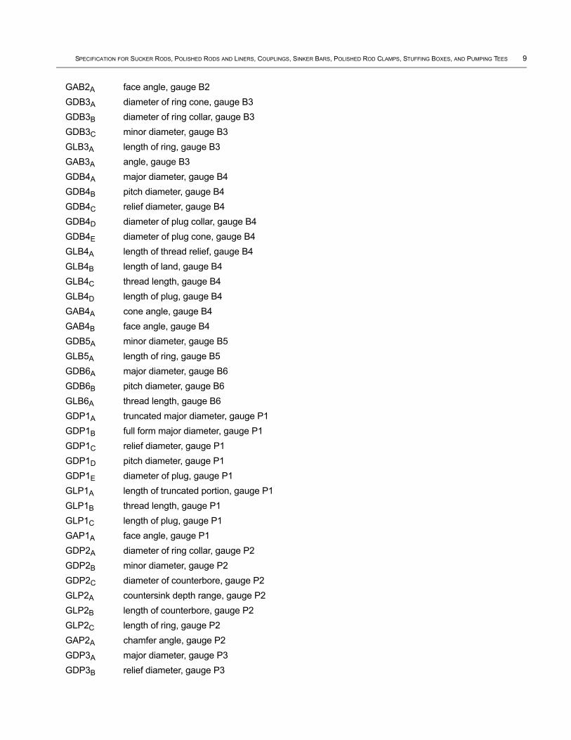
GAB2A face angle, gauge B2GDB3A diameter of ring cone, gauge B3GDB3B diameter of ring collar, gauge B3GDB3C minor diameter, gauge B3GLB3A length of ring, gauge B3GAB3A angle, gauge B3GDB4A major diameter, gauge B4GDB4B pitch diameter, gauge B4GDB4C relief diameter, gauge B4GDB4D diameter of plug collar, gauge B4GDB4E diameter of plug cone, gauge B4GLB4A length of thread relief, gauge B4GLB4B length of land, gauge B4GLB4C thread length, gauge B4GLB4D length of plug, gauge B4GAB4A cone angle, gauge B4GAB4B face angle, gauge B4GDB5A minor diameter, gauge B5GLB5A length of ring, gauge B5GDB6A major diameter, gauge B6GDB6B pitch diameter, gauge B6GLB6A thread length, gauge B6GDP1A truncated major diameter, gauge P1GDP1B full form major diameter, gauge P1GDP1C relief diameter, gauge P1GDP1D pitch diameter, gauge P1GDP1E diameter of plug, gauge P1GLP1A length of truncated portion, gauge P1GLP1B thread length, gauge P1GLP1C length of plug, gauge P1GAP1A face angle, gauge P1GDP2A diameter of ring collar, gauge P2GDP2B minor diameter, gauge P2GDP2C diameter of counterbore, gauge P2GLP2A countersink depth range, gauge P2GLP2B length of counterbore, gauge P2GLP2C length of ring, gauge P2GAP2A chamfer angle, gauge P2GDP3A major diameter, gauge P3GDP3B relief diameter, gauge P3
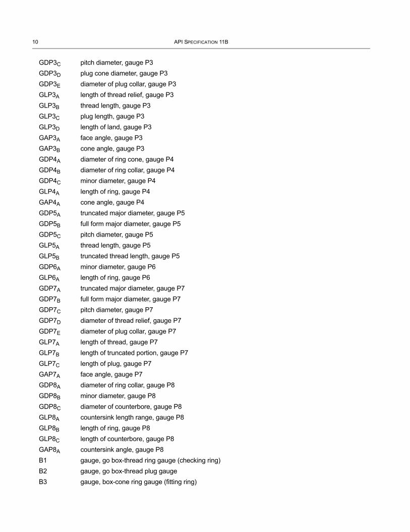
10 API SPECIFICATION 11B
GDP3C pitch diameter, gauge P3GDP3D plug cone diameter, gauge P3GDP3E diameter of plug collar, gauge P3GLP3A length of thread relief, gauge P3GLP3B thread length, gauge P3GLP3C plug length, gauge P3GLP3D length of land, gauge P3GAP3A face angle, gauge P3GAP3B cone angle, gauge P3GDP4A diameter of ring cone, gauge P4GDP4B diameter of ring collar, gauge P4GDP4C minor diameter, gauge P4GLP4A length of ring, gauge P4GAP4A cone angle, gauge P4GDP5A truncated major diameter, gauge P5GDP5B full form major diameter, gauge P5GDP5C pitch diameter, gauge P5GLP5A thread length, gauge P5GLP5B truncated thread length, gauge P5GDP6A minor diameter, gauge P6GLP6A length of ring, gauge P6GDP7A truncated major diameter, gauge P7GDP7B full form major diameter, gauge P7GDP7C pitch diameter, gauge P7GDP7D diameter of thread relief, gauge P7GDP7E diameter of plug collar, gauge P7GLP7A length of thread, gauge P7GLP7B length of truncated portion, gauge P7GLP7C length of plug, gauge P7GAP7A face angle, gauge P7GDP8A diameter of ring collar, gauge P8GDP8B minor diameter, gauge P8GDP8C diameter of counterbore, gauge P8GLP8A countersink length range, gauge P8GLP8B length of ring, gauge P8GLP8C length of counterbore, gauge P8GAP8A countersink angle, gauge P8B1 gauge, go box-thread ring gauge (checking ring)B2 gauge, go box-thread plug gaugeB3 gauge, box-cone ring gauge (fitting ring)

SPECIFICATION FOR SUCKER RODS, POLISHED RODS AND LINERS, COUPLINGS, SINKER BARS, POLISHED ROD CLAMPS, STUFFING BOXES, AND PUMPING TEES 11
B4 gauge, box-cone plug gaugeB5 gauge, no-go box-thread ring gauge (checking ring)B6 gauge, no-go box-thread plug gaugeP1 gauge, go pin-thread truncated setting plug gaugeP2 gauge, go pin-thread ring gaugeP3 gauge, go pin-cone plug gauge (fitting plug)P4 gauge, pin-cone ring gaugeP5 gauge, no-go pin-thread truncated setting plug gaugeP6 gauge, no-go pin-thread ring gaugeP7 gauge, go pin-thread truncated setting plug gaugeP8 gauge, go pin-thread ring gauge
5 Functional Requirements
To order products which conform to this specification, the user or purchaser may determine the applicable well and environmental operational conditions, specify the requirements and/or identify the supplier’s or manufacturer’s specific products. Additional detailed ordering information can be found in Annex A through Annex H. Requirements may be conveyed to the manufacturer by means of the manufacturer’s part number, data sheet, or other suitable documentation.
The following requirements may be specified as applicable:
a) required fluid volume or loads to be applied to the products;
b) material type and grade;
c) well depth, pump size, tubing size, or other mechanical well parameters;
d) well bore configuration (such as deviation, dog-legs, etc.);
e) produced fluid chemical and physical composition, including produced solids (sand production, scale, etc.), to which the products are exposed during their full life cycle;
f) the selected surface drive system;
g) pressure ratings, if applicable;
h) bottom hole static temperature and pressure;
i) planned chemical treatments;
j) bottom hole producing temperature and pressure.
6 Technical Requirements
6.1 General Requirements
Products designed and manufactured prior to the publication of this specification and in conformance with API 11B, 26th edition shall be considered as meeting the requirements of this specification.
12 API SPECIFICATION 11B
6.2 Design Requirements
6.2.1 General
The design shall conform to the requirements of this specification.
6.2.2 Design Documentation
Design documentation shall as a minimum include drawings, and as applicable: assumptions, formulas, calculations, design requirements, testing, and acceptance criteria. Design documentation medium shall be clear, legible, reproducible, and retrievable. It shall include design verification, validation, reviews, and any necessary actions.
6.2.3 Design Review
Designs shall be reviewed and verified by a qualified person other than the person(s) who developed the original design to evaluate the ability of the design to meet requirements.
6.2.4 Design Verification
Design verification shall be performed to ensure that each product design meets the manufacturer’s technical specifications.
6.2.5 Design Validation
Design validation shall be performed to ensure that the resulting product is capable of meeting the requirements for the specified application or intended use.
6.2.6 Design Changes
Design changes and changes to design documents that affect conformance to this specification shall require application of the same control features as those used to develop the original design.
6.3 Materials
6.3.1 General
The manufacturer shall have and conform to documented specifications for all materials used in products manufactured to this specification.
Products shall be manufactured in accordance with the materials specified in the applicable annexes.
6.3.2 Metals
6.3.2.1 General
Materials used for the manufacture of products made in accordance with this specification shall be as specified in the applicable annex.
6.3.2.2 Material Test Report (MTR)
Material test reports of materials used to manufacture products with traceability requirements shall include; the date of manufacture, mill heat number, chemical composition, hardness, yield strength, ultimate tensile strength, elongation and reduction in area, as applicable. These documents shall be maintained by the manufacturer for a period of at least five years. These records shall be provided to the end user as requested.

SPECIFICATION FOR SUCKER RODS, POLISHED RODS AND LINERS, COUPLINGS, SINKER BARS, POLISHED ROD CLAMPS, STUFFING BOXES, AND PUMPING TEES 13
6.3.3 Non-metallic Materials for FRP Sucker Rods
The manufacturer’s written specifications for non-metallic materials shall define those characteristics critical to the performance of the material. Included in these specifications are items such as composition, physical properties, mechanical properties, storage, and labeling requirements, as applicable.
7 Manufacturer Requirements7.1 General
As a minimum, each of the following topics shall be addressed by the manufacturer.
7.2 Quality Control
7.2.1 General
To maintain accuracy, equipment used to measure, test and gauge products manufactured in accordance with this specification shall be identified, controlled, calibrated and adjusted, if necessary. This shall be performed at specified intervals in accordance with the manufacturer’s specifications and the requirements of this specification.
Specific testing, and inspection criteria, including dimensional inspection and gauging, for each specific product are listed in the applicable annex.
Technologies for inspections with verifiable accuracies equal to or better than those listed in this specification may be applied with appropriate documentation approved by a qualified person.
7.2.2 Inspection/Measuring/Testing Equipment Calibration (Except for Thread Gauges)
Inspection, measuring, and testing equipment used for acceptance shall be identified, inspected, calibrated, and adjusted at specific intervals in accordance with documented procedures, and this specification. The calibration or verification of measuring and testing equipment used for product acceptance shall be traceable to the applicable national or specifications agency. Inspection, measuring, and testing equipment shall be used only within the calibrated range. Calibration shall conform with the requirements of ANSI NCSL Z540-1 or equivalent national standard. See Annex I for the calibration of thread gauges.
Calibration intervals for measuring and testing equipment shall be established based on repeatability and degree of usage. Calibration intervals shall be a maximum of three months until a recorded calibration history is established. Intervals may be lengthened or shortened based on calibration history. A calibration interval cannot be increased by more than twice the previous interval.
Calibration standards used to calibrate measuring and testing equipment shall be checked and approved at least once a year by an independent calibration agency with traceability to NIST or the applicable national or specifications agency.
7.2.3 Personnel Qualifications
All personnel performing quality control activities directly affecting material and product quality shall be qualified in accordance with the manufacturer's documented requirements.
7.2.4 Product Acceptance
7.2.4.1 General
Products designed and manufactured in accordance with this specification shall meet the requirements of the appropriate annexes of this specification. Records shall be maintained for a minimum of five years for all accepted
14 API SPECIFICATION 11B
finished products. When specified, non-destructive examinations shall be performed and accepted according to the manufacturer’s documented specifications which include acceptance criteria.
Dimensional inspection shall be performed by a qualified person to assure proper function and conformance with design criteria, specifications and final component dimensions.
7.2.4.2 Frequency and Acceptance of Inspection
7.2.4.2.1 Batch Lot Processing
Unless otherwise stated in this specification, frequency and acceptance of inspection of manufacturing lots shall be in accordance with the acceptance criteria for the single sampling plan for normal inspection, general inspection level I, acceptable quality level of 4.0 %, as specified in ANSI/ASQC Z1, or ISO 2859-1. More stringent inspection plans are acceptable.
NOTE ISO 11462-1 gives guidance and requirements on statistical process control.
The frequency and acceptance of inspection of manufacturing lots for pumping tees, polished rod clamps, polished rod liners, and stuffing boxes shall be in accordance with the acceptance criteria for the single sampling plan for normal inspection, general inspection level S2, acceptable quality level of 10.0 % as specified in ANSI/ASQC Z1, OR ISO 2859-1.
NOTE For the purposes of this specification ANSI/ASQ Z1.4 is equivalent to ISO 2859-1.
7.2.4.2.2 Continuous Processing
In continuous processing, a minimum of 10.0 % of the produced parts shall be inspected. Processing of non-conforming items shall conform to 7.2.5. Parts manufactured prior to the non-conforming items shall be inspected back to the last acceptable part and the non-conforming parts shall be dispositioned according to the manufacturer's documented procedures.
Acceptance criteria may be based on continuous monitoring and statistical process control such as described in ISO 11462-1.
7.2.4.3 Threads
Any product thread accepted by a calibrated reference master gauge or calibrated working gauge shall be considered as meeting product requirements.
7.2.5 Manufacturing Non-conformances
The manufacturer shall establish and maintain documented procedures to ensure that product which does not conform to specified requirements is prevented from unintended use or installation. This control shall provide for identification, evaluation, segregation, and disposition of non-conforming assemblies or components.
The responsibility for review and authority for the disposition of non-conforming product shall be defined by the manufacturer. Non-conforming product shall be:
a) reworked to meet the specified requirements or the specified requirements of another product;

SPECIFICATION FOR SUCKER RODS, POLISHED RODS AND LINERS, COUPLINGS, SINKER BARS, POLISHED ROD CLAMPS, STUFFING BOXES, AND PUMPING TEES 15
b) accepted without repair by concession of a manufacturer’s qualified and authorized person, provided the concession is within the design acceptance criteria and at no time is this product allowed to violate the requirements of this specification; or
c) rejected or scrapped.
Records of the nature of nonconformities and any subsequent actions taken, including concessions obtained, shall be maintained in accordance with manufacturer’s documented procedures.
7.2.6 Coatings
Coatings shall be controlled by documented processing instructions, which include acceptance criteria which have been approved by a qualified person.
7.2.7 Heat Treating Furnace Instrumentation
Automatic controlling and recording instruments shall be used. Thermocouples shall be located in the furnace working zone(s). The controlling and recording instruments used for the heat treatment processes shall possess an accuracy to within ±1 % of their full scale range. Temperature controlling and recording instruments shall be calibrated at least once every six months until a documented calibration history can be established. Calibration intervals shall then be established based on repeatability, degree of usage and documented calibration history. Equipment used to calibrate the furnace equipment shall possess an accuracy to within ±0.25 % of full scale range.
7.2.8 Non-Destructive Examination (NDE)
When NDE is utilized, instructions shall be detailed in the manufacturer’s documented procedures and conform to the requirements of this specification. All NDE instructions shall be approved by a Level III examiner qualified in accordance with an international or national standard such as ISO 9712 or ASNT Recommended Practice SNT-TC-1A.
Personnel performing NDE shall be qualified to at least Level II for evaluation and interpretation in accordance with an international or national standard such as ISO 9712 or ASNT Recommended Practice SNT-TC-1A. Any unacceptable indications shall be removed, repaired, and re-examined using the original NDE method.
In case discontinuities are detected by non-visual NDE methods, the evaluation may be supplemented by visual examination and measurement to determine the size of the discontinuity at the option of the manufacturer.
7.2.9 Traceability
All products manufactured under this specification shall be traceable as required by the applicable annex. Traceability shall be in accordance with the manufacturer’s documented procedures. Traceability is considered sufficient if the product meets the traceability requirements of this specification when it leaves the manufacturer’s inventory.
7.3 Product Identification
All products manufactured under this specification shall be marked in accordance with the requirements detailed in the appropriate normative Annex and the manufacturer’s documented procedures.
7.4 Documentation
The manufacturer shall establish and maintain documented procedures to control documents and data required by this specification. These documents and data shall be clear, legible, reproducible and retrievable. These documents and data shall be retained in facilities that provide an environment which minimizes damage, deterioration, or loss. Documents and data may be in the form of any type of media, such as hard copy or electronic media, and shall be retained for a minimum of five years from the date of manufacture.
Annex A(normative)
Steel Sucker Rods and Pony Rods
A.1 General
Steel sucker rods and steel pony rods shall be manufactured and supplied according to the requirements and specifications provided in this specification.
The application of sucker rod guides which affect the original mechanical, physical, or dimensional properties of the rod itself such that it no longer conforms to this specification, is not acceptable.
A.2 Design Requirements
A.2.1 General
The following general requirements shall be followed in the design of steel sucker rods and steel pony rods.
A.2.2 Dimensional Requirements
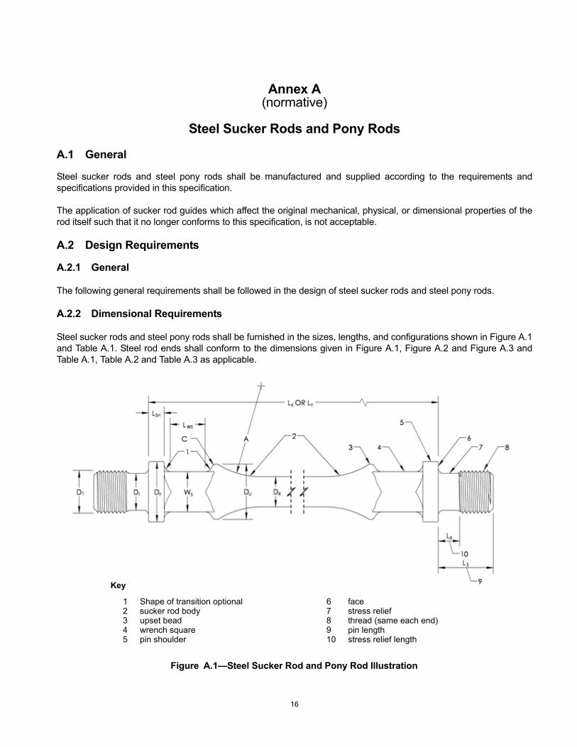
Steel sucker rods and steel pony rods shall be furnished in the sizes, lengths, and configurations shown in Figure A.1 and Table A.1. Steel rod ends shall conform to the dimensions given in Figure A.1, Figure A.2 and Figure A.3 and Table A.1, Table A.2 and Table A.3 as applicable.
Key
1 Shape of transition optional 6 face2 sucker rod body 7 stress relief3 upset bead 8 thread (same each end)4 wrench square 9 pin length5 pin shoulder 10 stress relief length
Figure A.1—Steel Sucker Rod and Pony Rod Illustration
16
SPECIFICATION FOR SUCKER RODS, POLISHED RODS AND LINERS, COUPLINGS, SINKER BARS, POLISHED ROD CLAMPS, STUFFING BOXES, AND PUMPING TEES 17
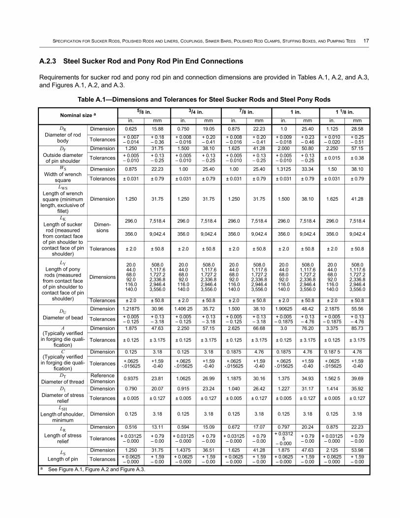
A.2.3 Steel Sucker Rod and Pony Rod Pin End Connections
Requirements for sucker rod and pony rod pin and connection dimensions are provided in Tables A.1, A.2, and A.3, and Figures A.1, A.2, and A.3.
Table A.1—Dimensions and Tolerances for Steel Sucker Rods and Steel Pony Rods
Nominal size a5/8 in. 3/4 in. 7/8 in. 1 in. 1 1/8 in.
in. mm in. mm in. mm in. mm in. mm DR
Diameter of rod body
Dimension 0.625 15.88 0.750 19.05 0.875 22.23 1.0 25.40 1.125 28.58
Tolerances + 0.007– 0.014
+ 0.18– 0.36
+ 0.008– 0.016
+ 0.20– 0.41
+ 0.008– 0.016
+ 0.20– 0.41
+ 0.009– 0.018
+ 0.23– 0.46
+ 0.010– 0.020
+ 0.25– 0.51
DFOutside diameter of pin shoulder
Dimension 1.250 31.75 1.500 38.10 1.625 41.28 2.000 50.80 2.250 57.15
Tolerances + 0.005– 0.010
+ 0.13– 0.25
+ 0.005– 0.010
+ 0.13– 0.25
+ 0.005– 0.010
+ 0.13– 0.25
+ 0.005– 0.010
+ 0.13– 0.25 ± 0.015 ± 0.38
WSWidth of wrench
square
Dimension 0.875 22.23 1.00 25.40 1.00 25.40 1.3125 33.34 1.50 38.10
Tolerances ± 0.031 ± 0.79 ± 0.031 ± 0.79 ± 0.031 ± 0.79 ± 0.031 ± 0.79 ± 0.031 ± 0.79LWS
Length of wrench square (minimum
length, exclusive of fillet)
Dimension 1.250 31.75 1.250 31.75 1.250 31.75 1.500 38.10 1.625 41.28
LKLength of sucker rod (measured
from contact face of pin shoulder to contact face of pin
shoulder)
Dimen-sions
296.0 7,518.4 296.0 7,518.4 296.0 7,518.4 296.0 7,518.4 296.0 7,518.4
356.0 9,042.4 356.0 9,042.4 356.0 9,042.4 356.0 9,042.4 356.0 9,042.4
Tolerances ± 2.0 ± 50.8 ± 2.0 ± 50.8 ± 2.0 ± 50.8 ± 2.0 ± 50.8 ± 2.0 ± 50.8
LYLength of pony rods (measured
from contact face of pin shoulder to contact face of pin
shoulder)
Dimensions
20.044.068.092.0116.0140.0
508.01,117.61,727.22,336.82,946.43,556.0
20.044.068.092.0116.0140.0
508.01,117.61,727.22,336.82,946.43,556.0
20.044.068.092.0116.0140.0
508.01,117.61,727.22,336.82,946.43,556.0
20.044.068.092.0116.0140.0
508.01,117.61,727.22,336.82,946.43,556.0
20.044.068.092.0116.0140.0
508.01,117.61,727.22,336.82,946.43,556.0
Tolerances ± 2.0 ± 50.8 ± 2.0 ± 50.8 ± 2.0 ± 50.8 ± 2.0 ± 50.8 ± 2.0 ± 50.8
DUDiameter of bead
Dimension 1.21875 30.96 1.406 25 35.72 1.500 38.10 1.90625 48.42 2.1875 55.56
Tolerances + 0.005– 0.125
+ 0.13– 3.18
+ 0.005– 0.125
+ 0.13– 3.18
+ 0.005– 0.125
+ 0.13– 3.18
+ 0.005– 0.1875
+ 0.13– 4.76
+ 0.005– 0.1875
+ 0.13– 4.76
A(Typically verified
in forging die quali-fication)
Dimension 1.875 47.63 2.250 57.15 2.625 66.68 3.0 76.20 3.375 85.73
Tolerances ± 0.125 ± 3.175 ± 0.125 ± 3.175 ± 0.125 ± 3.175 ± 0.125 ± 3.175 ± 0.125 ± 3.175
C(Typically verified
in forging die quali-fication)
Dimension 0.125 3.18 0.125 3.18 0.1875 4.76 0.1875 4.76 0.187 5 4.76
Tolerances +.0625-.015625
+1.59-0.40
+.0625-.015625
+1.59-0.40
+.0625-.015625
+1.59-0.40
+.0625-.015625
+1.59-0.40
+.0625-.015625
+1.59-0.40
DTDiameter of thread
Reference Dimension 0.9375 23.81 1.0625 26.99 1.1875 30.16 1.375 34.93 1.562 5 39.69
D1Diameter of stress
relief
Dimension 0.790 20.07 0.915 23.24 1.040 26.42 1.227 31.17 1.414 35.92
Tolerances ± 0.005 ± 0.127 ± 0.005 ± 0.127 ± 0.005 ± 0.127 ± 0.005 ± 0.127 ± 0.005 ± 0.127
LSHLength of shoulder,
minimumDimension 0.125 3.18 0.125 3.18 0.125 3.18 0.125 3.18 0.125 3.18
LRLength of stress
relief
Dimension 0.516 13.11 0.594 15.09 0.672 17.07 0.797 20.24 0.875 22.23
Tolerances + 0.03125– 0.000
+ 0.79– 0.00
+ 0.03125– 0.000
+ 0.79– 0.00
+ 0.03125– 0.000
+ 0.79– 0.00
+ 0.03125
– 0.000+ 0.79– 0.00
+ 0.03125– 0.000
+ 0.79– 0.00
LSLength of pin
Dimension 1.250 31.75 1.4375 36.51 1.625 41.28 1.875 47.63 2.125 53.98
Tolerances + 0.0625– 0.000
+ 1.59– 0.00
+ 0.0625– 0.000
+ 1.59– 0.00
+ 0.0625– 0.000
+ 1.59– 0.00
+ 0.0625– 0.000
+ 1.59– 0.00
+ 0.0625– 0.000
+ 1.59– 0.00
a See Figure A.1, Figure A.2 and Figure A.3.
18 API SPECIFICATION 11B
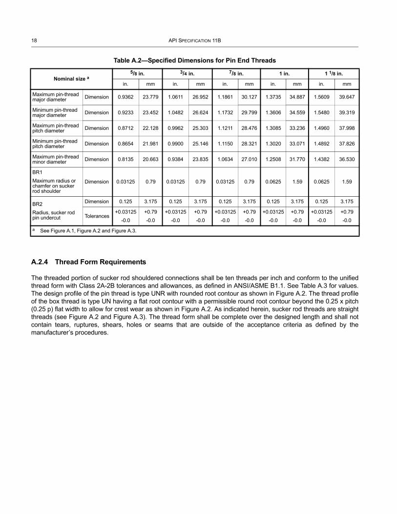
A.2.4 Thread Form Requirements
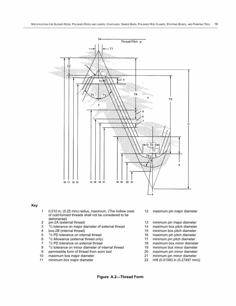
The threaded portion of sucker rod shouldered connections shall be ten threads per inch and conform to the unified thread form with Class 2A-2B tolerances and allowances, as defined in ANSI/ASME B1.1. See Table A.3 for values. The design profile of the pin thread is type UNR with rounded root contour as shown in Figure A.2. The thread profile of the box thread is type UN having a flat root contour with a permissible round root contour beyond the 0.25 x pitch (0.25 p) flat width to allow for crest wear as shown in Figure A.2. As indicated herein, sucker rod threads are straight threads (see Figure A.2 and Figure A.3). The thread form shall be complete over the designed length and shall not contain tears, ruptures, shears, holes or seams that are outside of the acceptance criteria as defined by the manufacturer’s procedures.
Table A.2—Specified Dimensions for Pin End Threads
Nominal size a5/8 in. 3/4 in. 7/8 in. 1 in. 1 1/8 in.
in. mm in. mm in. mm in. mm in. mm
Maximum pin-thread major diameter Dimension 0.9362 23.779 1.0611 26.952 1.1861 30.127 1.3735 34.887 1.5609 39.647
Minimum pin-thread major diameter Dimension 0.9233 23.452 1.0482 26.624 1.1732 29.799 1.3606 34.559 1.5480 39.319
Maximum pin-thread pitch diameter Dimension 0.8712 22.128 0.9962 25.303 1.1211 28.476 1.3085 33.236 1.4960 37.998
Minimum pin-thread pitch diameter Dimension 0.8654 21.981 0.9900 25.146 1.1150 28.321 1.3020 33.071 1.4892 37.826
Maximum pin-thread minor diameter Dimension 0.8135 20.663 0.9384 23.835 1.0634 27.010 1.2508 31.770 1.4382 36.530
BR1Maximum radius or chamfer on sucker rod shoulder
Dimension 0.03125 0.79 0.03125 0.79 0.03125 0.79 0.0625 1.59 0.0625 1.59
BR2Radius, sucker rod pin undercut
Dimension 0.125 3.175 0.125 3.175 0.125 3.175 0.125 3.175 0.125 3.175
Tolerances+0.03125
-0.0+0.79-0.0
+0.03125-0.0
+0.79-0.0
+0.03125-0.0
+0.79-0.0
+0.03125-0.0
+0.79-0.0
+0.03125-0.0
+0.79-0.0
a See Figure A.1, Figure A.2 and Figure A.3.
SPECIFICATION FOR SUCKER RODS, POLISHED RODS AND LINERS, COUPLINGS, SINKER BARS, POLISHED ROD CLAMPS, STUFFING BOXES, AND PUMPING TEES 19
Key1 0.010 in. (0.25 mm) radius, maximum, (The hollow crest
of cold-formed threads shall not be considered to be detrimental)
12 maximum pin major diameter
2 pin-2A (external thread) 13 minimum pin major diameter3 1/2 tolerance on major diameter of external thread 14 maximum box pitch diameter4 box-2B (internal thread) 15 minimum box pitch diameter5 1/2 PD tolerance on internal thread 16 maximum pin pitch diameter6 1/2 Allowance (external thread only) 17 minimum pin pitch diameter7 1/2 PD tolerance on external thread 18 maximum box minor diameter8 1/2 tolerance on minor diameter of internal thread 19 minimum box minor diameter9 permissible form of thread from worn tool 20 maximum pin minor diameter
10 maximum box major diameter 21 minimum pin minor diameter11 minimum box major diameter 22 H/8 (0.01083 in (0.27497 mm))
Figure A.2—Thread Form

20 API SPECIFICATION 11B
Table A.3—Thread Form Dimensional Relationships a, d
Dimensional element Figure Label Relationship Value
in.Valuemm
Height of sharp thread H 0.86603p 0.086603 2.199716
Design form height of pin-thread none 11H/16 0.059539 1.512305
Basic depth of pin crest truncation none H/8 0.01083 0.27508
Basic depth of pin root truncation none H/8 0.01083 0.27508
Radius of basic pin root none H/8 0.01083 0.27508
Allowance at pin root for worn tool none H/24 0.00361 0.09169
Basic height of box thread none 5H/8 0.05413 1.37490
Basic depth of box minor diameter truncation none H/4 0.02165 0.54991
Basic depth of box major diameter truncation 22 H/8 0.01083 0.27497
Pin major diameter tolerance b none 0.012927 0.3283
Pin pitch diameter tolerance b none — —
Box pitch diameter tolerance b none 1.3 x pin pitch diameter tolerance — —
Box minor diameter tolerance none 0.02100 0.533
Pin allowance b none 0.30 × pin pitch diameter tolerance, in. — —
2 × box thread height b none 1.250H 0.10825 2.750
2 × pin-thread addendum b none 3/4H 0.06495 1.650
Thread pitch p ---- 0.100 2.54
T1 ---- 0.00416 0.1057
T2c ---- 0.0125 0.3175
T3 ---- 30° 30°
T4 ---- 0.03969 1.008
T5 ---- 0.05413 1.375
T6 ---- 0.025 0.635
T7 ---- 0.01443 0.3665
T8 ---- 0.01083 0.2751a See Figure A.2.
b See ANSI/ASME B1.1 for balance of formula.
c Half Pitch.
d Calculations shall be performed in U.S. customary units and converted to SI when completed.
0.060 p23( ) in.
0.015 D3
+0.015 Le3
+0.015 p23⎝ ⎠⎜ ⎟⎜ ⎟⎜ ⎟⎜ ⎟⎛ ⎞
in.
0.25p 1.4p2–( ) in.
SPECIFICATION FOR SUCKER RODS, POLISHED RODS AND LINERS, COUPLINGS, SINKER BARS, POLISHED ROD CLAMPS, STUFFING BOXES, AND PUMPING TEES 21
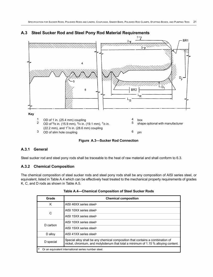
A.3 Steel Sucker Rod and Steel Pony Rod Material Requirements
A.3.1 General
Steel sucker rod and steel pony rods shall be traceable to the heat of raw material and shall conform to 6.3.
A.3.2 Chemical Composition
The chemical composition of steel sucker rods and steel pony rods shall be any composition of AISI series steel, or equivalent, listed in Table A.4 which can be effectively heat treated to the mechanical property requirements of grades K, C, and D rods as shown in Table A.5.
Table A.4—Chemical Composition of Steel Sucker Rods
Grade Chemical composition
K AISI 46XX series steela
CAISI 10XX series steela
AISI 15XX series steela
D carbonAISI 10XX series steela
AISI 15XX series steela
D alloy AISI 41XX series steela
D special Special alloy shall be any chemical composition that contains a combination of nickel, chromium, and molybdenum that total a minimum of 1.15 % alloying content.
a Or an equivalent international series number steel.
Key1 OD of 1 in. (25.4 mm) coupling 4 box 2 OD of 5/8 in. (15.9 mm), 3/4 in. (19.1 mm), 7/8 in.
(22.2 mm), and 11/8 in. (28.6 mm) coupling
5 shape optional with manufacturer
3 OD of slim hole coupling 6 pin
Figure A.3—Sucker Rod Connection
22 API SPECIFICATION 11B
A.3.3 Chemical Analysis
Chemical analysis shall be performed on each mill heat of steel used in the manufacture of sucker rods or pony rods. This analysis shall be performed in accordance with ASTM A751. A material test report (MTR) is an acceptable means to conform to this requirement.
A.4 Mechanical Properties
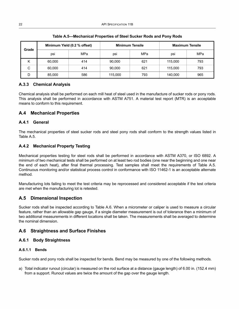
A.4.1 General
The mechanical properties of steel sucker rods and steel pony rods shall conform to the strength values listed in Table A.5.
A.4.2 Mechanical Property Testing
Mechanical properties testing for steel rods shall be performed in accordance with ASTM A370, or ISO 6892. A minimum of two mechanical tests shall be performed on at least two rod bodies (one near the beginning and one near the end of each heat), after final thermal processing. Test samples shall meet the requirements of Table A.5. Continuous monitoring and/or statistical process control in conformance with ISO 11462-1 is an acceptable alternate method.
Manufacturing lots failing to meet the test criteria may be reprocessed and considered acceptable if the test criteria are met when the manufacturing lot is retested.
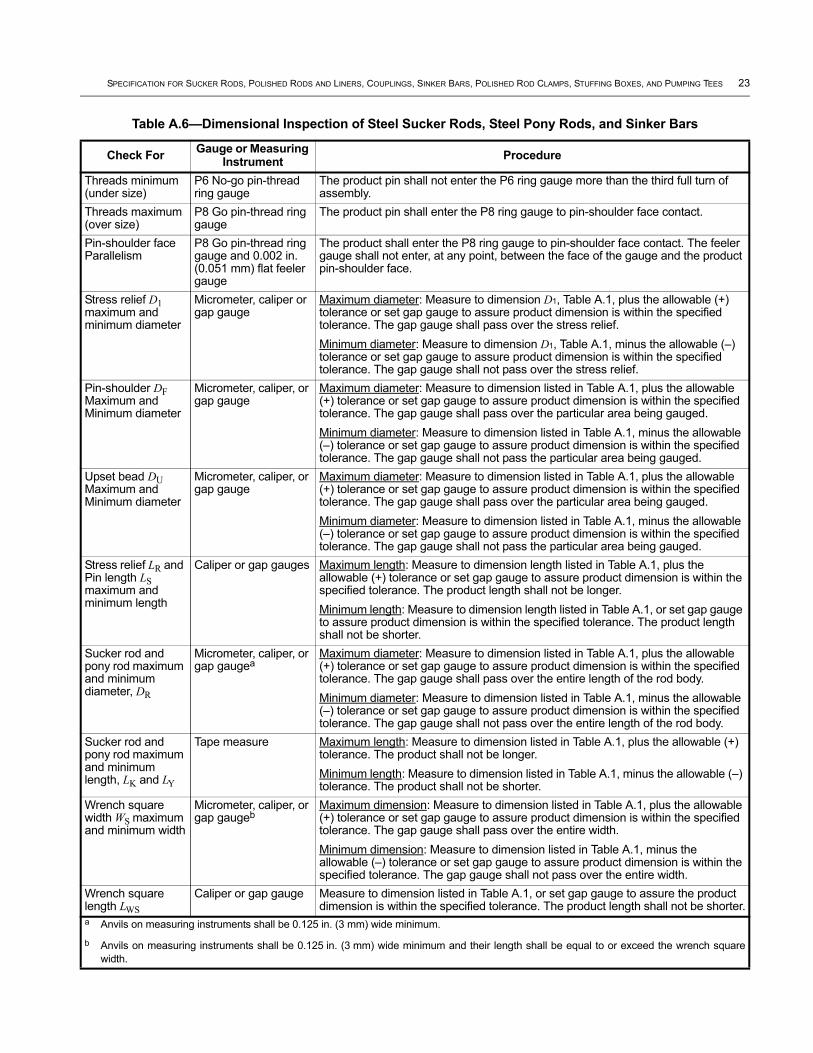
A.5 Dimensional Inspection
Sucker rods shall be inspected according to Table A.6. When a micrometer or caliper is used to measure a circular feature, rather than an allowable gap gauge, if a single diameter measurement is out of tolerance then a minimum of two additional measurements in different locations shall be taken. The measurements shall be averaged to determine the nominal dimension.
A.6 Straightness and Surface Finishes
A.6.1 Body Straightness
A.6.1.1 Bends
Sucker rods and pony rods shall be inspected for bends. Bend may be measured by one of the following methods.
a) Total indicator runout (circular) is measured on the rod surface at a distance (gauge length) of 6.00 in. (152.4 mm) from a support. Runout values are twice the amount of the gap over the gauge length.
Table A.5—Mechanical Properties of Steel Sucker Rods and Pony Rods
GradeMinimum Yield (0.2 % offset) Minimum Tensile Maximum Tensile
psi MPa psi MPa psi MPa
K 60,000 414 90,000 621 115,000 793
C 60,000 414 90,000 621 115,000 793
D 85,000 586 115,000 793 140,000 965
SPECIFICATION FOR SUCKER RODS, POLISHED RODS AND LINERS, COUPLINGS, SINKER BARS, POLISHED ROD CLAMPS, STUFFING BOXES, AND PUMPING TEES 23
Table A.6—Dimensional Inspection of Steel Sucker Rods, Steel Pony Rods, and Sinker Bars
Check For Gauge or Measuring Instrument Procedure
Threads minimum (under size)
P6 No-go pin-thread ring gauge
The product pin shall not enter the P6 ring gauge more than the third full turn of assembly.
Threads maximum (over size)
P8 Go pin-thread ring gauge
The product pin shall enter the P8 ring gauge to pin-shoulder face contact.
Pin-shoulder face Parallelism
P8 Go pin-thread ring gauge and 0.002 in. (0.051 mm) flat feeler gauge
The product shall enter the P8 ring gauge to pin-shoulder face contact. The feeler gauge shall not enter, at any point, between the face of the gauge and the product pin-shoulder face.
Stress relief D1 maximum and minimum diameter
Micrometer, caliper or gap gauge
Maximum diameter: Measure to dimension D1, Table A.1, plus the allowable (+) tolerance or set gap gauge to assure product dimension is within the specified tolerance. The gap gauge shall pass over the stress relief.Minimum diameter: Measure to dimension D1, Table A.1, minus the allowable (–) tolerance or set gap gauge to assure product dimension is within the specified tolerance. The gap gauge shall not pass over the stress relief.
Pin-shoulder DF Maximum and Minimum diameter
Micrometer, caliper, or gap gauge
Maximum diameter: Measure to dimension listed in Table A.1, plus the allowable (+) tolerance or set gap gauge to assure product dimension is within the specified tolerance. The gap gauge shall pass over the particular area being gauged.Minimum diameter: Measure to dimension listed in Table A.1, minus the allowable (–) tolerance or set gap gauge to assure product dimension is within the specified tolerance. The gap gauge shall not pass the particular area being gauged.
Upset bead DU Maximum and Minimum diameter
Micrometer, caliper, or gap gauge
Maximum diameter: Measure to dimension listed in Table A.1, plus the allowable (+) tolerance or set gap gauge to assure product dimension is within the specified tolerance. The gap gauge shall pass over the particular area being gauged.Minimum diameter: Measure to dimension listed in Table A.1, minus the allowable (–) tolerance or set gap gauge to assure product dimension is within the specified tolerance. The gap gauge shall not pass the particular area being gauged.
Stress relief LR and Pin length LS maximum and minimum length
Caliper or gap gauges Maximum length: Measure to dimension length listed in Table A.1, plus the allowable (+) tolerance or set gap gauge to assure product dimension is within the specified tolerance. The product length shall not be longer.Minimum length: Measure to dimension length listed in Table A.1, or set gap gauge to assure product dimension is within the specified tolerance. The product length shall not be shorter.
Sucker rod and pony rod maximum and minimum diameter, DR
Micrometer, caliper, or gap gaugea
Maximum diameter: Measure to dimension listed in Table A.1, plus the allowable (+) tolerance or set gap gauge to assure product dimension is within the specified tolerance. The gap gauge shall pass over the entire length of the rod body.Minimum diameter: Measure to dimension listed in Table A.1, minus the allowable (–) tolerance or set gap gauge to assure product dimension is within the specified tolerance. The gap gauge shall not pass over the entire length of the rod body.
Sucker rod and pony rod maximum and minimum length, LK and LY
Tape measure Maximum length: Measure to dimension listed in Table A.1, plus the allowable (+) tolerance. The product shall not be longer.Minimum length: Measure to dimension listed in Table A.1, minus the allowable (–) tolerance. The product shall not be shorter.
Wrench square width WS maximum and minimum width
Micrometer, caliper, or gap gaugeb
Maximum dimension: Measure to dimension listed in Table A.1, plus the allowable (+) tolerance or set gap gauge to assure product dimension is within the specified tolerance. The gap gauge shall pass over the entire width.Minimum dimension: Measure to dimension listed in Table A.1, minus the allowable (–) tolerance or set gap gauge to assure product dimension is within the specified tolerance. The gap gauge shall not pass over the entire width.
Wrench square length LWS
Caliper or gap gauge Measure to dimension listed in Table A.1, or set gap gauge to assure the product dimension is within the specified tolerance. The product length shall not be shorter.
a Anvils on measuring instruments shall be 0.125 in. (3 mm) wide minimum.
b Anvils on measuring instruments shall be 0.125 in. (3 mm) wide minimum and their length shall be equal to or exceed the wrench square width.
24 API SPECIFICATION 11B
b) A 12.00 in. (304.8 mm) straight edge shall be held on the concave side of the bend. The amount of the bend is the gap measured between the straight edge and the concave rod surface.
A gauge length of 12.00 in. (304.8 mm) shall be used to determine the maximum allowable bend for all rod sizes 5/8 in. to 11/8 in. (15.88 mm to 28.58 mm). The maximum allowable gap is 0.065 in. (1.65 mm) measured on one side as described in b) above, or 0.130 in. (3.30 mm) total indicator runout (circular) as described in a) above.
A.6.1.2 Pony Rods 2 ft in Length
Body straightness for a nominally 2 ft long (length measurement) (0.61 m) pony rod shall be measured with a gauge length of 6.00 in. (152.4 mm). The amount of TIR bend is measured via a dial indicator riding on the rod body 3 in. (76.2 mm) from a support. The maximum allowable TIR values for all rod sizes 5/8 in. to 11/8 in. (15.88 mm to 28.58 mm) is 0.065 in. (1.65 mm). The maximum allowable gap value is 0.033 in. (0.84 mm).
A.6.1.3 Alternate Inspection Technologies
Technologies for inspections with verifiable accuracies equal to or better than those listed in this specification may be applied with appropriate documentation approved by a qualified person.
A.6.1.4 Kinks
Sucker rods and pony rods shall be inspected for kinks.
A kink shall be measured as follows: A 6.00 in. (152.4 mm) straight edge is held on the concave side of the kink. The amount of kink is the gap measured between the straight edge and the rod body surface. A gauge length of 6.00 in. (152.4 mm) shall be used to determine the maximum allowable gap. The maximum allowable gap in the middle of the gauge length is 0.125 in. (3.18 mm). Straightening of kinks is not acceptable and the rod must be rejected.
Technologies for inspections with verifiable accuracies equal to or better than those listed in this specification may be applied with appropriate documentation approved by a qualified person.
A.6.2 End Straightness
A.6.2.1 Sucker Rods and Pony Rods
End straightness shall be measured by supporting the rod body at a distance of 6.00 in. (152.4 mm) from the rod pin shoulder. The rest of the rod shall be supported at a maximum of 6.00 ft (1.83 m) with centers in the same plane. The amount of TIR bend is measured via a dial indicator, laser or other comparable measuring device. The amount of bend shall be measured at the machined surface of the pin shoulder OD. The maximum allowable TIR values for all rod sizes 5/8 in. to 11/8 in. (15.88 mm to 28.58 mm) is 0.130 in. (3.30 mm).
A.6.3 Surface finish, Rod Body
A.6.3.1 General
Surface finish shall conform to the requirements of this section.
Upon removal of a discontinuity, all dimensional requirements shall be met.
A.6.3.2 Discontinuities
When the depth of a discontinuity cannot be measured, the discontinuity shall be removed to attain a smooth transition.
SPECIFICATION FOR SUCKER RODS, POLISHED RODS AND LINERS, COUPLINGS, SINKER BARS, POLISHED ROD CLAMPS, STUFFING BOXES, AND PUMPING TEES 25
Discontinuities such as rolled-in scale, slivers, mechanical damage, etc., when removed, shall be removed to attain a smooth transition.
Longitudinal discontinuities are acceptable provided the depth or height does not exceed 0.020 in. (0.51 mm) from the adjacent surfaces. Longitudinal discontinuities which are less than 0.020 in. (0.51 mm) need not be removed.
Transverse discontinuities greater than 0.004 in. (0.10 mm) depth are unacceptable and shall be removed to attain a smooth transition.
Pits shall not exceed a depth of 0.008 in. (0.20 mm).
A.6.4 Surface Finish, Upset Area
A.6.4.1 General
The exterior surface of the upset area shall be inspected by qualified person(s) using the manufacturer's documented procedures. The inspection method shall be sufficient to identify the discontinuities as defined below.
Surface finish roughness of the machined upset area shall not be greater than 125 μin. (3.175 μm) Ra.
A.6.4.2 Discontinuities
When the depth of a discontinuity cannot be measured, the discontinuity shall be removed to attain a smooth transition.
Longitudinal discontinuities that occur in the area above the point where the upset diameter equals the width of the wrench square are acceptable. Longitudinal discontinuities which occur in any area of the upset from the rod body up to that point where the upset diameter equals the width of the wrench square are acceptable as long as the height or depth does not exceed 0.031 in. (0.79 mm). Longitudinal discontinuities which exceed 0.031 in. (0.79 mm) in this area shall be removed with a smooth transition provided that all dimensional tolerances are maintained.
Transverse discontinuities which are continuous around the upset, and deeper than 0.063 in. (1.60 mm), are unacceptable and shall be removed with a smooth transition. Upon removal of the discontinuity, all dimensional requirements shall be met. Transverse discontinuities deeper than 0.125 in. (3.18 mm) are unacceptable.
A.7 Packaging and Transportation Requirements for Finished Products
Packaging of steel sucker rods shall conform to the following requirements.
a) Prior to shipment, exposed metallic surfaces shall be protected with an atmospheric type of oil soluble rust preventative which shall not become fluid at a temperature less than 125 °F (52 °C).
b) Overall width of a steel sucker rod package shall be 30 in. ± 1 in. (762 mm ± 25 mm).
c) Maximum distance from edge of support/spacer to end of rod (coupling, if installed) shall be 20 in. (508 mm).
d) Maximum center-to-center distance down the length of the rod for supports and spacers shall be 72 in. (1.83 m).
e) Cross supports, spacers, and blocks shall be of material that is non-abrasive to the rod.
f) Supports shall be provided along the bottom of each bundle and shall be of such thickness as to prevent the rod ends or couplings from resting directly on a flat surface.
g) Spacers shall be provided such that rows of rod bodies do not contact each other during shipment.
26 API SPECIFICATION 11B
h) Rods shall be placed between supports and spacers such that the ends of supports and spacers extend beyond the packaged rods.
i) Packages shall be designed to support the rods and be designed to be lifted and laid down with a handling device, such as a spreader bar and T-hooks without damage to the rods.
j) Unpackaged rods shall always be lifted with a handling device, such as a spreader bar with nylon straps, so designed to support the rods without damage.
k) It is not acceptable to lift the rods and packages using chains, cables, wires or with a forklift when the tine comes into contact with the rod bodies.
l) Trucks and trailers for handling rods and packages shall be provided with blockage, as required for removal of the lifting device, placed directly under the crosswise supports of the package so that the rods themselves shall not be in contact with the blockage. Straps shall not apply stress to rod bodies. A minimum of three tie down straps shall be used and only placed in such positions as to pass over the crosswise supports.
m) When in storage or for transportation, the packages shall be stacked so that the bottom support shall rest squarely on the top support of the lower package.
n) In all handling operations, care shall be exercised to prevent rods or rod ends from contacts which might cause nicks or bends, or injury to the threads by jamming of the thread protectors. Further, the rods shall never be handled in such a manner as to produce a permanent kink or bend. Kinked, bent, or nicked rods are permanently damaged and shall be discarded.
o) Couplings, rod bodies, upsets, and wrench squares shall never be hammered on with metallic tools for any reason. One blow can so damage any part of a rod or coupling as to result in early failure.
A.8 Packaging of Steel Pony Rods
Pony rods shall be packaged according to manufacturer’s requirements such that the rods will not be damaged during shipping.
A.9 Thread Protectors
Thread protectors shall be designed to protect the pin or box thread and contact face from physical damage during normal transportation and handling.
External thread protectors shall be installed on all external threads.
Internal thread protectors shall be installed in the open ends of all couplings installed on sucker rods and pony rods.
Thread protector caps or internal coupling protectors shall be removed in a manner so as to not cause damage to the product.
A.10 Storage for Finished Products
Steel sucker rods and pony rods shall be separated and stored according to grade and size. They shall be stored in such locations and in such a manner as to minimize deterioration from exposure to corrosive environments. They shall be stacked off the ground on racks or sills made of or surfaced with a material not abrasive to the rods.
For packaged rods, a rack or sill shall be provided under each support of the package. The packages shall be stacked so that the supports are in vertical alignment. See A.7 for packaging requirements.
SPECIFICATION FOR SUCKER RODS, POLISHED RODS AND LINERS, COUPLINGS, SINKER BARS, POLISHED ROD CLAMPS, STUFFING BOXES, AND PUMPING TEES 27
For unpackaged rods, at least four rack or sill supports shall be provided and the end supports shall be located approximately 12 in. (300 mm) from the rod ends. The rod layers shall be separated by non-abrasive spacers placed directly above the rack or sill. The spacers shall be thick enough to prevent the rods from contacting adjacent layers. If the spacers are not notched, the outside rods in each layer shall be chocked to prevent the rods from rolling off the spacers.
Stored rods and pony rods shall be inspected at regular intervals. Any rust shall be removed with a wire brush and a suitable oil-soluble atmospheric corrosion protective coating applied.
A.11 Marking Requirements
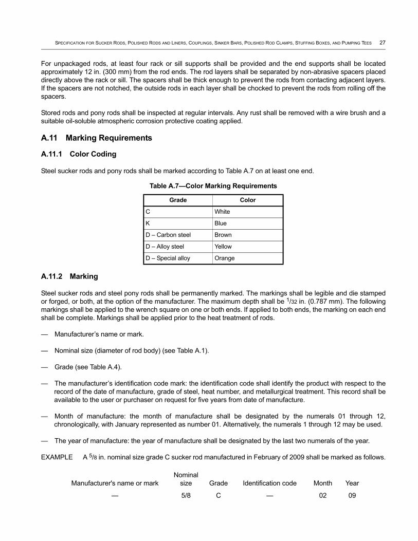
A.11.1 Color Coding
Steel sucker rods and pony rods shall be marked according to Table A.7 on at least one end.
A.11.2 Marking
Steel sucker rods and steel pony rods shall be permanently marked. The markings shall be legible and die stamped or forged, or both, at the option of the manufacturer. The maximum depth shall be 1/32 in. (0.787 mm). The following markings shall be applied to the wrench square on one or both ends. If applied to both ends, the marking on each end shall be complete. Markings shall be applied prior to the heat treatment of rods.
— Manufacturer’s name or mark.
— Nominal size (diameter of rod body) (see Table A.1).
— Grade (see Table A.4).
— The manufacturer’s identification code mark: the identification code shall identify the product with respect to the record of the date of manufacture, grade of steel, heat number, and metallurgical treatment. This record shall be available to the user or purchaser on request for five years from date of manufacture.
— Month of manufacture: the month of manufacture shall be designated by the numerals 01 through 12, chronologically, with January represented as number 01. Alternatively, the numerals 1 through 12 may be used.
— The year of manufacture: the year of manufacture shall be designated by the last two numerals of the year.
EXAMPLE A 5/8 in. nominal size grade C sucker rod manufactured in February of 2009 shall be marked as follows.
Table A.7—Color Marking Requirements
Grade Color
C White
K Blue
D – Carbon steel Brown
D – Alloy steel Yellow
D – Special alloy Orange
Manufacturer's name or markNominal
size Grade Identification code Month Year
— 5/8 C — 02 09
28 API SPECIFICATION 11B
Other additional markings are allowed and may be applied as desired by the manufacturer or as requested by the user or purchaser, but shall be applied after the markings specified above.
A.12 Ordering information
Suggestions for ordering steel sucker rods and steel pony rods are as follows:
a) grade,
b) nominal size (body diameter),
c) length,
d) quantity,
e) special packaging requirements, if required.
Annex B(normative)
Polished Rods and Liners
B.1 Sizes, Threads, and Couplings for Polished Rods
B.1.1 General
Polished rods and liners shall be manufactured and supplied according to the requirements and specifications provided in this specification.
B.1.2 Sizes
Polished rods shall be furnished in the nominal sizes shown in Table B.1.
Polished rod liners shall be furnished in the sizes shown in Table B.2.
B.1.3 Threads
Polished rods shall be furnished with polished rod pin threads on each end, as shown in Figure B.1.
B.1.4 Couplings
Couplings designed for use on polished rods shall conform to the requirements of Annex C for polished rod couplings.
NOTE The use of sucker rod couplings on polished rods can result in split couplings. The lack of matching tapers on sucker rod couplings and polished rod pins will prevent proper makeup.
B.2 Design Requirements
B.2.1 General
The following general requirements shall be followed in the design of polished rods and polished rod liners.
B.2.2 Dimensional Requirements
Polished rods shall be furnished in the sizes, lengths, and configuration shown in Figure B.1 and Table B.1. Threaded ends shall conform to the configuration shown in Figure B.1.
Polished rod liners shall be furnished in the sizes shown in Table B.2. Length and configuration are optional with the manufacturer.
B.2.3 Dimensions and Tolerances for Pin End Threads
Polished rod threads are straight threads with the imperfect pin-threads on the 9° vanish cone (see Figure B.1).
Requirements for polished rod pin and connection dimensions are provided in Table B.3.
Refer to Figure B.1 for polished-rod thread details.
Refer to Table B.4 for thread gauging requirements.
29
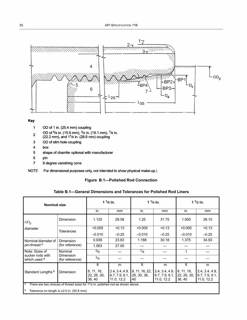
30 API SPECIFICATION 11B
Table B.1—General Dimensions and Tolerances for Polished Rod Liners
Nominal size1 1/8 in. 1 1/4 in. 1 1/2 in.
in. mm in. mm in. mm
ODp
diameter
Dimension 1.125 28.58 1.25 31.75 1.500 38.10
Tolerances+0.005
–0.010
+0.13
–0.25
+0.005
–0.010
+0.13
–0.25
+0.005
–0.010
+0.13
–0.25
Nominal diameter of pin-thread a
Dimension (for reference)
0.938 23.83 1.188 30.18 1.375 34.931.063 27.00 — — — —
Note: Sizes of sucker rods with which used a
Nominal Dimension (for reference)
5/8 — 7/8 — 1 —3/4 — — — — —
Standard Lengths b Dimension
ft
8, 11, 16, 22, 26, 30, 36, 40
m
2.4, 3.4, 4.9, 6.7, 7.9, 9.1, 11.0, 12.2
ft
8, 11, 16, 22, 26, 30, 36, 40
m
2.4, 3.4, 4.9, 6.7, 7.9, 9.1, 11.0, 12.2
ft
8, 11, 16, 22, 26, 30, 36, 40
m
2.4, 3.4, 4.9, 6.7, 7.9, 9.1, 11.0, 12.2
a There are two choices of thread sizes for 11/8 in. polished rod as shown above.
b Tolerance on length is ±2.0 in. (50.8 mm).
Key
NOTE For dimensional purposes only, not intended to show physical make-up.)
1 OD of 1 in. (25.4 mm) coupling
2 OD of 5/8 in. (15.9 mm), 3/4 in. (19.1 mm), 7/8 in. (22.2 mm), and 11/8 in. (28.6 mm) coupling
3 OD of slim hole coupling 4 box 5 shape of chamfer optional with manufacturer 6 pin7 9 degree vanishing cone
Figure B.1—Polished Rod Connection
Key
NOTE For dimensional purposes only, not intended to show physical make-up.
1 OD of 1 in. (25.4 mm) coupling
2 OD of 5/8 in. (15.9 mm), 3/4 in. (19.1 mm), 7/8 in. (22.2 mm), and 11/8 in. (28.6 mm) coupling
3 OD of slim hole coupling 4 box 5 shape of chamfer optional with manufacturer 6 pin7 9 degree vanishing cone

SPECIFICATION FOR SUCKER RODS, POLISHED RODS AND LINERS, COUPLINGS, SINKER BARS, POLISHED ROD CLAMPS, STUFFING BOXES, AND PUMPING TEES 31
The threaded portion of polished rod pins shall be ten threads per inch (four threads per centimeter) and conform to the unified thread form with Class 2A-2B tolerances and allowances, as defined in ANSI/ASME B1.1. The design profile of the pin-thread is type UNR with rounded root contour as shown in Figure A.2. The thread profile of the box thread is type UN having a flat root contour with a permissible round root contour beyond the 0.25 × pitch (0.25 p) flat width to allow for crest wear as shown in Figure A.2. As indicated herein, polished rod threads are straight threads with the imperfect pin threads on the 9° vanish cone (see Figure B.1).
B.2.4 Thread Form
Polished rod thread dimensions shall be per Table B.3.
B.3 Polished Rod Material RequirementsB.3.1 General
Polished rods shall be traceable to the heat of raw material and shall conform to 6.3.
B.3.2 Chemical Composition
The chemical composition of polished rods shall be any composition of AISI recommended series steels that conform to the chemical and mechanical property requirements listed below. The chemical composition and limits shall be detailed in the material specification of the manufacturer.
a) Carbon steel: AISI 1035 – 1050 7.
b) Stainless steel: AISI 304/316 or 431 7.
c) Alloy steel:
1) AISI 4120 – 4140 7;
2) AISI 4315 – 4340 7;
3) AISI 4615 – 4625 7;
4) AISI 8620 – 8630 7.
Chemical composition of polished rod liners shall be as specified by the manufacturer. Steel polished rod liners shall be sprayed metal coated.
Chemical analysis shall be performed on each mill heat of steel used in the manufacture of polished rods. This analysis shall be performed in accordance with ASTM A751. A material certification is an acceptable means to conform to this requirement.
Table B.2—General Dimensions for Polished Rod Liners
Polished Rod Liner Size, Outside Diameter a
Size of Polished Rod With Which Used, For Reference Only
in. mm in. mm
1.375 34.93 11/8 28.58
1.500 38.10 11/4 31.75
1.750 44.45 11/2 38.10a Tolerance on OD is +0.003 in. / –0.002 in. (+0.08 mm / –0.05 mm).
7 Or an equivalent international series number steel.
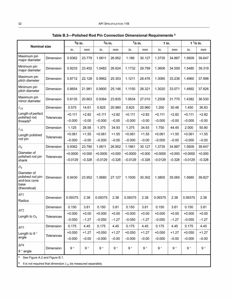
32 API SPECIFICATION 11B
Table B.3—Polished Rod Pin Connection Dimensional Requirements a
Nominal size5/8 in. 3/4 in. 7/8 in. 1 in. 1 1/8 in.
in. mm in. mm in. mm in. mm in. mm
Maximum pin major diameter Dimension 0.9362 23.779 1.0611 26.952 1.186 30.127 1.3735 34.887 1.5609 39.647
Minimum pin major diameter Dimension 0.9233 23.452 1.0482 26.624 1.1732 29.799 1.3606 34.559 1.5480 39.319
Maximum pin pitch diameter Dimension 0.8712 22.128 0.9962 25.303 1.1211 28.476 1.3085 33.236 1.4960 37.998
Minimum pin pitch diameter Dimension 0.8654 21.981 0.9900 25.146 1.1150 28.321 1.3020 33.071 1.4892 37.826
Maximum pin minor diameter Dimension 0.8135 20.663 0.9384 23.835 1.0634 27.010 1.2508 31.770 1.4382 36.530
L2S
Length of perfect polished rod threadsb
Dimension 0.575 14.61 0.825 20.960 0.825 20.960 1.200 30.48 1.450 36.83
Tolerances+0.111
–0.000
+2.82
–0.00
+0.111
–0.000
+2.82
–0.00
+0.111
–0.000
+2.82
–0.00
+0.111
–0.000
+2.82
–0.00
+0.111
–0.000
+2.82
–0.00
L3S
Length polished rod pin
Dimension 1.125 28.58 1.375 34.93 1.375 34.93 1.750 44.45 2.000 50.80
Tolerances+0.061
–0.000
+1.55
–0.00
+0.061
–0.000
+1.55
–0.00
+0.061
–0.000
+1.55
–0.00
+0.061
–0.000
+1.55
–0.00
+0.061
–0.000
+1.55
–0.00
DS
Diameter of polished rod pin shank
Dimension 0.9362 23.780 1.0611 26.952 1.1861 30.127 1.3735 34.887 1.5609 39.647
Tolerances+0.0000
–0.0129
+0.000
–0.328
+0.0000
–0.0129
+0.000
–0.328
+0.0000
–0.0129
+0.000
–0.328
+0.0000
–0.0129
+0.000
–0.328
+0.0000
–0.0129
+0.000
–0.328
D4
Diameter of polished rod pin-and-box cone base (theoretical)
Dimension 0.9430 23.952 1.0680 27.127 1.1930 30.302 1.3805 35.065 1.5680 39.827
BP1
RadiusDimension 0.09375 2.38 0.09375 2.38 0.09375 2.38 0.09375 2.38 0.09375 2.38
BP2
Length to D4
Dimension 0.150 3.81 0.150 3.81 0.150 3.81 0.150 3.81 0.150 3.81
Tolerances +0.000
–0.050
+0.00
–1.27
+0.000
–0.050
+0.00
–1.27
+0.000
–0.050
+0.00
–1.27
+0.000
–0.050
+0.00
–1.27
+0.000
–0.050
+0.00
–1.27
BP3
Length to 9 ° angle
Dimension 0.175 4.45 0.175 4.45 0.175 4.45 0.175 4.45 0.175 4.45
Tolerances +0.050
–0.000
+1.27
–0.00
+0.050
–0.000
+1.27
–0.00
+0.050
–0.000
+1.27
–0.00
+0.050
–0.000
+1.27
–0.00
+0.050
–0.000
+1.27
–0.00
BP4
9 ° angleDimension 9 ° 9 ° 9 ° 9 ° 9 ° 9 ° 9 ° 9 ° 9 ° 9 °
a See Figure A.2 and Figure B.1.
b It is not required that dimension L2S be measured separately.
SPECIFICATION FOR SUCKER RODS, POLISHED RODS AND LINERS, COUPLINGS, SINKER BARS, POLISHED ROD CLAMPS, STUFFING BOXES, AND PUMPING TEES 33
B.3.3 Mechanical Properties for Finished Product
The mechanical properties of polished rods shall conform to the strength values as follows:
a) for carbon steels listed in B.3.2, the ultimate tensile strength shall be in the range of 90,000 psi to 160,000 psi (621 MPa to 1,103 MPa);
b) for alloy steels listed in B.3.2, the ultimate tensile strength shall be in the range of 95,000 psi to 160,000 psi (655 MPa to 1,103 MPa);
c) for stainless steels listed in B.3.2, the minimum ultimate tensile strength shall be 70,000 psi (482 MPa) for 304/316, and 90,000 psi (620 MPa) for 431.
NOTE Ultimate tensile strength of sprayed metal polished rods shall be controlled by process verification or other means specified by the manufacturer.
B.4 Inspection and Testing
B.4.1 Mechanical Property Testing
Mechanical properties tests for polished rods shall be performed in accordance with ASTM A370, ISO 6892 or verified by a material test report (MTR).
B.4.2 Dimensional Inspection
Dimensional inspection of polished rods shall be performed in accordance with Table B.4.
Dimensional inspection of polished rod liners shall be performed in accordance with Table B.2.
B.4.3 Rejected Polished Rods and Polish Rod Liners
Rejected rods and liners may be reworked according to the manufacturer's documented procedure and re-inspected in accordance with B.4.2.
B.4.4 Surface Finish
Surface finish roughness of polished rods and liners shall be checked with a surface finish gauge such as a profilometer or a comparator and shall have a surface finish of 8 μin. to 32 μin. (0.203 μm to 0.813 μm) Ra.
B.5 Sprayed Metal Polished Rod and Liner Requirements
Base metal shall be prepared prior to sprayed metal coating in accordance with the manufacturer’s procedure and specification to assure adequate bonding. Examples of effective surface preparation procedures are specified in SSPC-SP 5/NACE No. 1 or SSPC-SP 11.
The finished outside diameter of sprayed metal polished rods shall conform to Table B.1, except the tolerance on the OD between pin end and start of sprayed metal shall be +0.005 in. / – 0.040 in. (+0.13 mm / – 1.02 mm). The length of the sprayed metal surface shall be determined by the manufacturer. The chemical composition of the coating shall be per Table B.5.
The sprayed metal coating thickness for polished rods shall be 0.008 in. to 0.020 in. (0.20 mm to 0.51 mm) per side, as verified by diameter measurements before and after sprayed metal coating, or by using a commercial thickness tester.
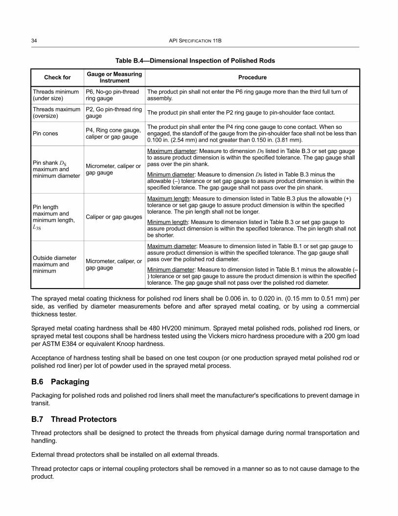
34 API SPECIFICATION 11B
The sprayed metal coating thickness for polished rod liners shall be 0.006 in. to 0.020 in. (0.15 mm to 0.51 mm) per side, as verified by diameter measurements before and after sprayed metal coating, or by using a commercial thickness tester.
Sprayed metal coating hardness shall be 480 HV200 minimum. Sprayed metal polished rods, polished rod liners, or sprayed metal test coupons shall be hardness tested using the Vickers micro hardness procedure with a 200 gm load per ASTM E384 or equivalent Knoop hardness.
Acceptance of hardness testing shall be based on one test coupon (or one production sprayed metal polished rod or polished rod liner) per lot of powder used in the sprayed metal process.
B.6 PackagingPackaging for polished rods and polished rod liners shall meet the manufacturer's specifications to prevent damage in transit.
B.7 Thread ProtectorsThread protectors shall be designed to protect the threads from physical damage during normal transportation and handling.
External thread protectors shall be installed on all external threads.
Thread protector caps or internal coupling protectors shall be removed in a manner so as to not cause damage to the product.
Table B.4—Dimensional Inspection of Polished Rods
Check for Gauge or Measuring Instrument Procedure
Threads minimum (under size)
P6, No-go pin-thread ring gauge
The product pin shall not enter the P6 ring gauge more than the third full turn of assembly.
Threads maximum (oversize)
P2, Go pin-thread ring gauge The product pin shall enter the P2 ring gauge to pin-shoulder face contact.
Pin cones P4, Ring cone gauge, caliper or gap gauge
The product pin shall enter the P4 ring cone gauge to cone contact. When so engaged, the standoff of the gauge from the pin-shoulder face shall not be less than 0.100 in. (2.54 mm) and not greater than 0.150 in. (3.81 mm).
Pin shank DS maximum and minimum diameter
Micrometer, caliper or gap gauge
Maximum diameter: Measure to dimension DS listed in Table B.3 or set gap gauge to assure product dimension is within the specified tolerance. The gap gauge shall pass over the pin shank.
Minimum diameter: Measure to dimension DS listed in Table B.3 minus the allowable (–) tolerance or set gap gauge to assure product dimension is within the specified tolerance. The gap gauge shall not pass over the pin shank.
Pin length maximum and minimum length, L3S
Caliper or gap gauges
Maximum length: Measure to dimension listed in Table B.3 plus the allowable (+) tolerance or set gap gauge to assure product dimension is within the specified tolerance. The pin length shall not be longer.
Minimum length: Measure to dimension listed in Table B.3 or set gap gauge to assure product dimension is within the specified tolerance. The pin length shall not be shorter.
Outside diameter maximum and minimum
Micrometer, caliper, or gap gauge
Maximum diameter: Measure to dimension listed in Table B.1 or set gap gauge to assure product dimension is within the specified tolerance. The gap gauge shall pass over the polished rod diameter.
Minimum diameter: Measure to dimension listed in Table B.1 minus the allowable (–) tolerance or set gap gauge to assure the product dimension is within the specified tolerance. The gap gauge shall not pass over the polished rod diameter.
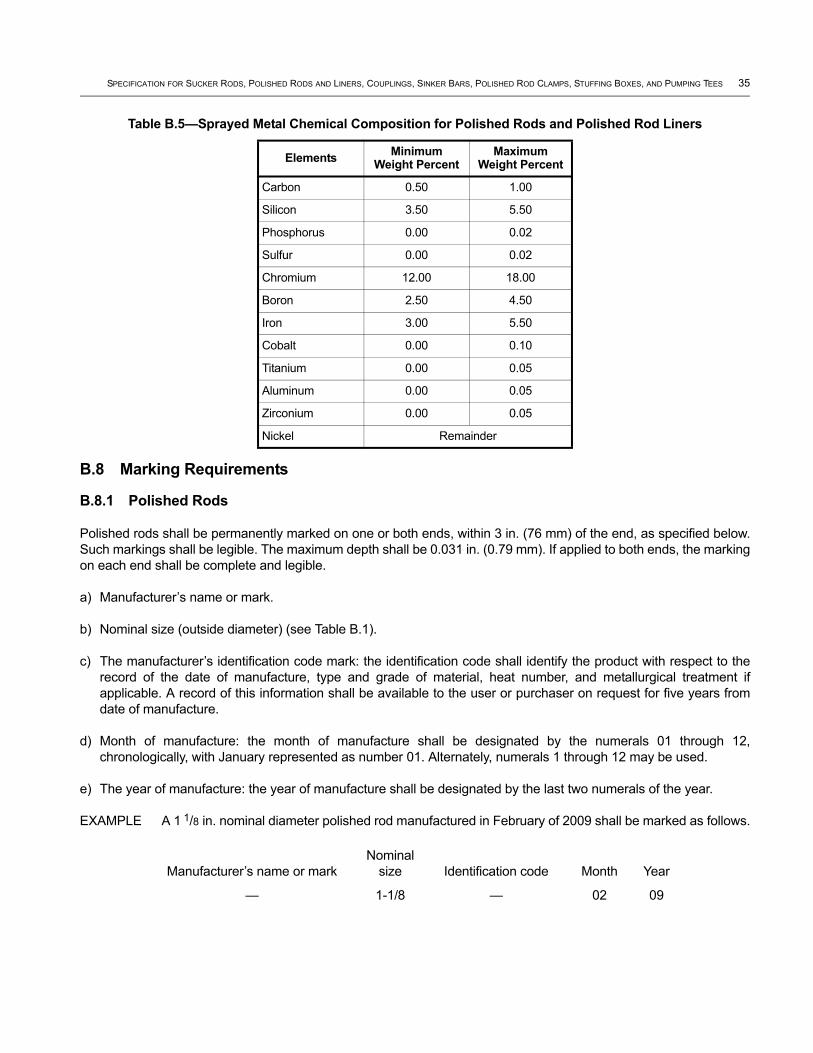
SPECIFICATION FOR SUCKER RODS, POLISHED RODS AND LINERS, COUPLINGS, SINKER BARS, POLISHED ROD CLAMPS, STUFFING BOXES, AND PUMPING TEES 35
B.8 Marking Requirements
B.8.1 Polished Rods
Polished rods shall be permanently marked on one or both ends, within 3 in. (76 mm) of the end, as specified below. Such markings shall be legible. The maximum depth shall be 0.031 in. (0.79 mm). If applied to both ends, the marking on each end shall be complete and legible.
a) Manufacturer’s name or mark.
b) Nominal size (outside diameter) (see Table B.1).
c) The manufacturer’s identification code mark: the identification code shall identify the product with respect to the record of the date of manufacture, type and grade of material, heat number, and metallurgical treatment if applicable. A record of this information shall be available to the user or purchaser on request for five years from date of manufacture.
d) Month of manufacture: the month of manufacture shall be designated by the numerals 01 through 12, chronologically, with January represented as number 01. Alternately, numerals 1 through 12 may be used.
e) The year of manufacture: the year of manufacture shall be designated by the last two numerals of the year.
EXAMPLE A 1 1/8 in. nominal diameter polished rod manufactured in February of 2009 shall be marked as follows.
Table B.5—Sprayed Metal Chemical Composition for Polished Rods and Polished Rod Liners
Elements Minimum Weight Percent
Maximum Weight Percent
Carbon 0.50 1.00
Silicon 3.50 5.50
Phosphorus 0.00 0.02
Sulfur 0.00 0.02
Chromium 12.00 18.00
Boron 2.50 4.50
Iron 3.00 5.50
Cobalt 0.00 0.10
Titanium 0.00 0.05
Aluminum 0.00 0.05
Zirconium 0.00 0.05
Nickel Remainder
Manufacturer’s name or markNominal
size Identification code Month Year
— 1-1/8 — 02 09

36 API SPECIFICATION 11B
B.8.2 Polished Rod Liners
Polished rod liners shall be permanently marked. Such markings shall be legible.
a) Manufacturer’s name or mark.
b) Month of manufacture: the month of manufacture shall be designated by the numerals 01 through 12, chronologically, with January represented as number 01. Alternatively, the numerals 1 through 12 may be used.
c) The year of manufacture: the year of manufacture shall be designated by the last two numerals of the year.
EXAMPLE A polished rod liner manufactured in February of 2009 shall be marked as follows.
B.9 Ordering Information
B.9.1 Polished Rods
Suggestions for ordering polished rods are as follows:
a) size (nominal outside diameter),
b) length,
c) end connections (nominal diameter of pin threads),
d) base material,
e) sprayed metal length if sprayed metal surface is chosen as an option, (length and location of sprayed metal surface),
f) quantity.
B.9.2 Polished Rod Liners
Suggestions for ordering polished rod liners are listed below:
a) size (outside diameter),
b) length,
c) quantity.
Manufacturer’s name or mark Month Year
— 02 09
Annex C(normative)
Sucker Rod Couplings, Polished Rod Couplings, and Sub-couplings
C.1 Couplings
C.1.1 General
Sucker rod couplings, polished rod couplings, and sub-couplings shall be manufactured and supplied according to the requirements provided in this specification and are used as connections for sucker rods, sinker bars, pony rods and polished rods, as applicable.
Sucker rod couplings, polished rod couplings, and sub-couplings may be manufactured as Class T (through-hardened) or Class SM (sprayed metal). Unless specified otherwise, the requirements listed below apply to both classes.
C.1.2 Sucker Rod Couplings
Sucker rod couplings have the same box thread size in each end and are used for connecting sucker rods and/or pony rods, and/or sinker bars with sucker rod threads. Dimensions shall conform to Table C.1 and Table C.2, Figure C.1 and Figure C.2, as applicable.
NOTE The use of sucker rod couplings on polished rods will result in the failure of the polished rod pin or coupling.
C.1.3 Polished Rod Couplings
Polished rod couplings have the same box thread size in each end and are used for connecting the polished rod and/or sinker bars with polished rod threads to the sucker rod string. Dimensions shall conform to Table C.1 and Table C.2, and Figure C.1 and Figure C.3 as applicable.
C.1.4 Sub-couplings
Sub-couplings have different sizes of box threads in each end and are used for connecting two sizes of sucker rods or a polished rod to a sucker rod string. External dimensions shall conform to Table C.1. Outside diameter (OD) and other dimensions shall conform to the larger coupling thread in Table C.1. Sub-coupling thread dimensions shall conform to Table C.2 and Figure C.3 as applicable.
Sub-couplings may be used on sucker rods or polished rods.
C.2 Design Requirements
C.2.1 General
The following general requirements shall be followed in the design of sucker rod couplings, polished rod couplings and sub-couplings.
C.2.2 Dimensional Requirements
Sucker rod couplings, polished rod couplings, and sub-couplings shall be furnished in the sizes, lengths, and configuration shown in Figure C.1 and Table C.1.
37

38 API SPECIFICATION 11B
C.2.3 Specified Dimensions and Tolerances
External dimensions of sucker rod couplings, polished rod couplings, and sub-couplings shall conform to Table C.1.
C.2.4 Thread Form Requirements
Coupling and sub-coupling thread form shall be in accordance with A.2.4.
C.2.5 Pin and Box Requirements
Box connections shall conform to the dimensions of Figure C.2 for sucker rod threads or Figure C.3 for polished rod threads.
L
ODD2
D3
D2
D3
D2
D3
L
OD
L
OD
Subcoupling
Polished-rod coupling
Sucker-rod coupling (do not use on polished rod)
Figure C.1—Sucker Rod Coupling, Polished Rod Coupling, and Sub-Coupling
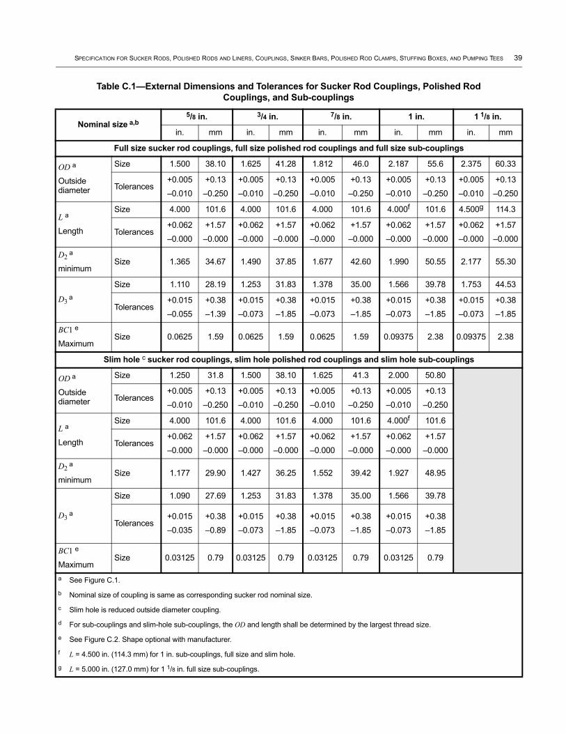
SPECIFICATION FOR SUCKER RODS, POLISHED RODS AND LINERS, COUPLINGS, SINKER BARS, POLISHED ROD CLAMPS, STUFFING BOXES, AND PUMPING TEES 39
Table C.1—External Dimensions and Tolerances for Sucker Rod Couplings, Polished Rod Couplings, and Sub-couplings
Nominal size a,b5/8 in. 3/4 in. 7/8 in. 1 in. 1 1/8 in.
in. mm in. mm in. mm in. mm in. mm
Full size sucker rod couplings, full size polished rod couplings and full size sub-couplings
OD a
Outside diameter
Size 1.500 38.10 1.625 41.28 1.812 46.0 2.187 55.6 2.375 60.33
Tolerances+0.005
–0.010
+0.13
–0.250
+0.005
–0.010
+0.13
–0.250
+0.005
–0.010
+0.13
–0.250
+0.005
–0.010
+0.13
–0.250
+0.005
–0.010
+0.13
–0.250
L a
Length
Size 4.000 101.6 4.000 101.6 4.000 101.6 4.000f 101.6 4.500g 114.3
Tolerances+0.062
–0.000
+1.57
–0.000
+0.062
–0.000
+1.57
–0.000
+0.062
–0.000
+1.57
–0.000
+0.062
–0.000
+1.57
–0.000
+0.062
–0.000
+1.57
–0.000
D2 a
minimumSize 1.365 34.67 1.490 37.85 1.677 42.60 1.990 50.55 2.177 55.30
D3 a
Size 1.110 28.19 1.253 31.83 1.378 35.00 1.566 39.78 1.753 44.53
Tolerances+0.015
–0.055
+0.38
–1.39
+0.015
–0.073
+0.38
–1.85
+0.015
–0.073
+0.38
–1.85
+0.015
–0.073
+0.38
–1.85
+0.015
–0.073
+0.38
–1.85
BC1 e
MaximumSize 0.0625 1.59 0.0625 1.59 0.0625 1.59 0.09375 2.38 0.09375 2.38
Slim hole c sucker rod couplings, slim hole polished rod couplings and slim hole sub-couplings
OD a
Outside diameter
Size 1.250 31.8 1.500 38.10 1.625 41.3 2.000 50.80
Tolerances+0.005
–0.010
+0.13
–0.250
+0.005
–0.010
+0.13
–0.250
+0.005
–0.010
+0.13
–0.250
+0.005
–0.010
+0.13
–0.250
L a
Length
Size 4.000 101.6 4.000 101.6 4.000 101.6 4.000f 101.6
Tolerances+0.062
–0.000
+1.57
–0.000
+0.062
–0.000
+1.57
–0.000
+0.062
–0.000
+1.57
–0.000
+0.062
–0.000
+1.57
–0.000
D2 a
minimumSize 1.177 29.90 1.427 36.25 1.552 39.42 1.927 48.95
D3 a
Size 1.090 27.69 1.253 31.83 1.378 35.00 1.566 39.78
Tolerances+0.015
–0.035
+0.38
–0.89
+0.015
–0.073
+0.38
–1.85
+0.015
–0.073
+0.38
–1.85
+0.015
–0.073
+0.38
–1.85
BC1 e
MaximumSize 0.03125 0.79 0.03125 0.79 0.03125 0.79 0.03125 0.79
a See Figure C.1.
b Nominal size of coupling is same as corresponding sucker rod nominal size.
c Slim hole is reduced outside diameter coupling.
d For sub-couplings and slim-hole sub-couplings, the OD and length shall be determined by the largest thread size.
e See Figure C.2. Shape optional with manufacturer.
f L = 4.500 in. (114.3 mm) for 1 in. sub-couplings, full size and slim hole.
g L = 5.000 in. (127.0 mm) for 1 1/8 in. full size sub-couplings.

40 API SPECIFICATION 11B
Table C.2—Dimensional Requirements for Polished Rod and Sucker Rod Box Connections
Nominal size a,b5/8 in. 3/4 in. 7/8 in. 1 in. 1 1/8 in.
in. mm in. mm in. mm in. mm in. mm
Diameter of thread Size 0.938 23.83 1.063 27.00 1.188 30.18 1.375 34.93 1.563 39.70
Lnb c,d
Total depth of box minimum
Dimension 1.750 44.45 1.938 49.23 2.125 53.98 2.500 63.50 2.750 69.85
L3n c,d
Total length of threads in box including counterbore, min
Dimension 1.410 35.81 1.600 40.64 1.790 45.47 2.000 50.80 2.250 57.15
Minimum box major diameter (basic) e
Dimension 0.9380 23.825 1.0630 27.000 1.1880 30.175 1.3754 34.935 1.5630 39.700
Maximum box pitch diameter e Dimension 0.8806 22.367 1.0060 25.552 1.1310 28.727 1.3190 33.503 1.5068 38.273
Minimum box pitch diameter (basic) e
Dimension 0.8730 22.174 0.9980 25.349 1.1230 28.524 1.3105 33.287 1.4980 38.049
Maximum box minor diameter e Dimension 0.851 21.62 0.976 24.79 1.101 27.97 1.288 32.72 1.476 37.49
Minimum box minor diameter e Dimension 0.830 21.08 0.955 24.26 1.080 27.43 1.267 32.18 1.455 36.96
BC2 c
Counterbore depth, sucker rod coupling
Dimension 0.4375 11.113 0.4375 11.113 0.4375 11.113 0.4375 11.113 0.4375 11.113
Tolerances+0.0625
–0.0000
+1.588
–0.000
+0.0625
–0.0000
+1.588
–0.000
+0.0625
–0.0000
+1.588
–0.000
+0.0625
–0.0000
+1.588
–0.000
+0.0625
–0.0000
+1.588
–0.000
BC3 c
Thread chamfer angle
Dimension 30° 30° 30° 30° 30° 30° 30° 30° 30° 30°
BC4 d
Counterbore depth, polished rod coupling
Dimension 0.250 6.35 0.250 6.35 0.250 6.35 0.250 6.35 0.250 6.35
Tolerances +0.050
–0.000
+1.27
–0.00
+0.050
–0.000
+1.27
–0.00
+0.050
–0.000
+1.27
–0.00
+0.050
–0.000
+1.27
–0.00
+0.050
–0.000
+1.27
–0.00
DQ c,d,f
Diameter of box counterbore
Dimension 0.955 24.26 1.080 27.43 1.205 30.61 1.393 35.38 1.580 40.13
Tolerances+0.010
–0.000
+0.25
–0.00
+0.010
–0.000
+0.25
–0.00
+0.010
–0.000
+0.25
–0.00
+0.010
–0.000
+0.25
–0.00
+0.010
–0.000
+0.25
–0.00a The hollow crest of cold-formed threads shall not be considered detrimental.
b See Table B.3 for polished rod box theoretical cone base dimension D4.
c See Figure C.2.
d See Figure C.3.
e See Figure A.2.
f Tapping marks in the counterbore shall not be reason for rejection.

SPECIFICATION FOR SUCKER RODS, POLISHED RODS AND LINERS, COUPLINGS, SINKER BARS, POLISHED ROD CLAMPS, STUFFING BOXES, AND PUMPING TEES 41
C.3 Steel Coupling and Sub-coupling Material Requirements
C.3.1 General
Couplings and sub-couplings shall be traceable to the heat of raw material and shall conform to 6.3.
C.3.2 Chemical Composition
The material shall be per manufacturer’s specification and shall have a maximum sulfur content of 0.05 %.
C.3.3 Chemical Analysis
Chemical analysis shall be performed on each mill heat of steel used in the manufacture of couplings or sub-couplings. This analysis shall be performed in accordance with ASTM A751. A material test report (MTR) is an acceptable means to conform to this requirement.
Figure C.2—Sucker Rod Coupling Illustration
Key1 Plane of end of thread in box 6 Shape of coupling chamfer optional with manufacturer 2 Shape optional with manufacturer 7 OD of slim hole coupling3 Pin 8 OD of 5/8 in. (15.9 mm), 3/4 in. (19.1 mm), 7/8 in. (22.2 mm),
and 11/8 in. (28.6 mm) coupling4 Coupling thread continuous at
manufacturer’s option9 OD of 1 in. (25.4 mm) coupling
5 Box
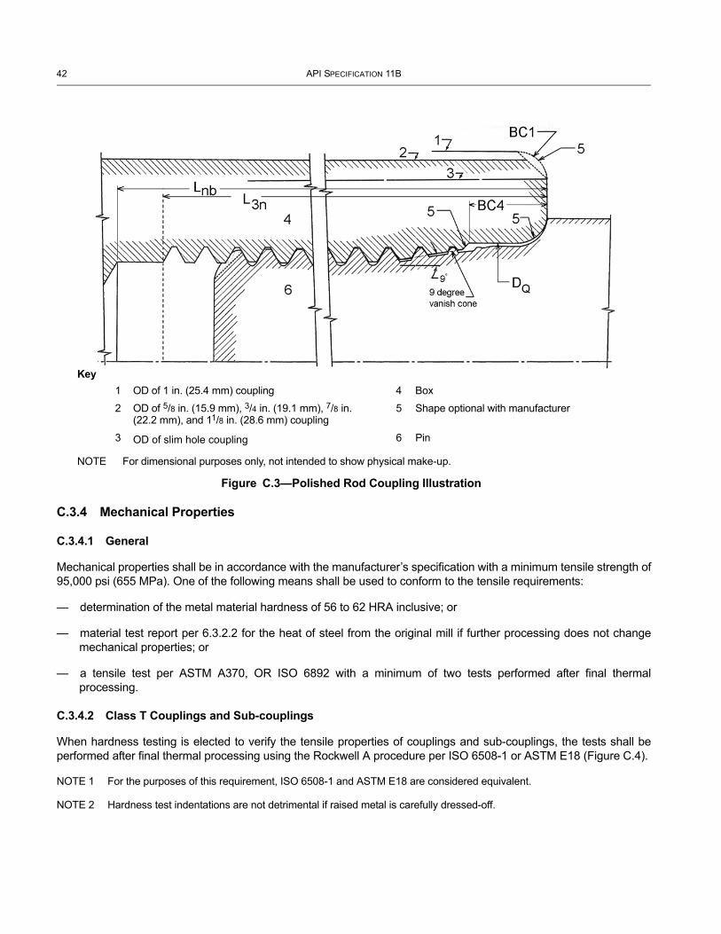
42 API SPECIFICATION 11B
C.3.4 Mechanical Properties
C.3.4.1 General
Mechanical properties shall be in accordance with the manufacturer’s specification with a minimum tensile strength of 95,000 psi (655 MPa). One of the following means shall be used to conform to the tensile requirements:
— determination of the metal material hardness of 56 to 62 HRA inclusive; or
— material test report per 6.3.2.2 for the heat of steel from the original mill if further processing does not change mechanical properties; or
— a tensile test per ASTM A370, OR ISO 6892 with a minimum of two tests performed after final thermal processing.
C.3.4.2 Class T Couplings and Sub-couplings
When hardness testing is elected to verify the tensile properties of couplings and sub-couplings, the tests shall be performed after final thermal processing using the Rockwell A procedure per ISO 6508-1 or ASTM E18 (Figure C.4).
NOTE 1 For the purposes of this requirement, ISO 6508-1 and ASTM E18 are considered equivalent.
NOTE 2 Hardness test indentations are not detrimental if raised metal is carefully dressed-off.
Figure C.3—Polished Rod Coupling Illustration
Key
NOTE For dimensional purposes only, not intended to show physical make-up.
1 OD of 1 in. (25.4 mm) coupling 4 Box
2 OD of 5/8 in. (15.9 mm), 3/4 in. (19.1 mm), 7/8 in. (22.2 mm), and 11/8 in. (28.6 mm) coupling
5 Shape optional with manufacturer
3 OD of slim hole coupling 6 Pin

SPECIFICATION FOR SUCKER RODS, POLISHED RODS AND LINERS, COUPLINGS, SINKER BARS, POLISHED ROD CLAMPS, STUFFING BOXES, AND PUMPING TEES 43
C.4 Sprayed Metal Coating Requirements
C.4.1 Chemical Composition
The chemical composition of the coating shall conform to Table C.3.
C.4.2 Mechanical Properties
Spray metal coating hardness testing shall be performed on a minimum of one sprayed metal test coupon per lot of coating, or on one coupling or sub-coupling per lot of coating, or on one sprayed metal test coupon per 5,000 products, or on one coupling or sub-coupling per 5,000 products.
Testing shall be by the Vickers micro-hardness procedure with a 200 g load in accordance with ASTM E384 or equivalent Knoop hardness with Va dimension (see Figure C.5) being 0.003 in. to 0.013 in. (0.08 mm to 0.33 mm).
Sprayed metal coating hardness shall be 595 HV200 minimum.
C.4.3 Base Metal Preparation
Base metal shall be prepared as specified in SSPC-SP 5/NACE No. 1 prior to sprayed metal coating in accordance with manufacturer’s procedure and specification.
2
1
4
3
5
Figure C.4—Rockwell A Hardness Determination of Base Metal
Key1 hardness tester penetrator 4 approximate mid-point
2 anvil or table 5 exposed base metal
3 sprayed metal coating
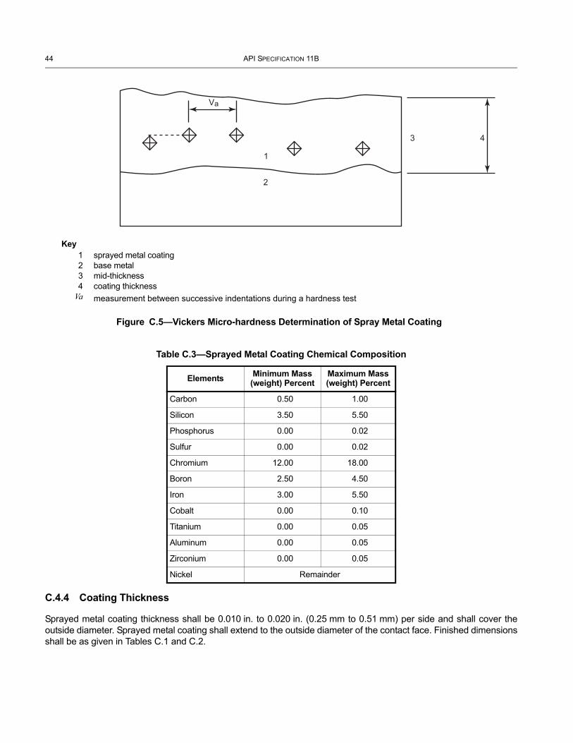
44 API SPECIFICATION 11B
C.4.4 Coating Thickness
Sprayed metal coating thickness shall be 0.010 in. to 0.020 in. (0.25 mm to 0.51 mm) per side and shall cover the outside diameter. Sprayed metal coating shall extend to the outside diameter of the contact face. Finished dimensions shall be as given in Tables C.1 and C.2.
Table C.3—Sprayed Metal Coating Chemical Composition
Elements Minimum Mass (weight) Percent
Maximum Mass (weight) Percent
Carbon 0.50 1.00
Silicon 3.50 5.50
Phosphorus 0.00 0.02
Sulfur 0.00 0.02
Chromium 12.00 18.00
Boron 2.50 4.50
Iron 3.00 5.50
Cobalt 0.00 0.10
Titanium 0.00 0.05
Aluminum 0.00 0.05
Zirconium 0.00 0.05
Nickel Remainder
1
3 4
2
Va
Figure C.5—Vickers Micro-hardness Determination of Spray Metal Coating
Key1 sprayed metal coating2 base metal3 mid-thickness4 coating thickness
Va measurement between successive indentations during a hardness test
SPECIFICATION FOR SUCKER RODS, POLISHED RODS AND LINERS, COUPLINGS, SINKER BARS, POLISHED ROD CLAMPS, STUFFING BOXES, AND PUMPING TEES 45
C.5 Coupling and Sub-coupling Surface Finish
C.5.1 General
The surface finish roughness of the outside diameter of Class T couplings shall not be rougher than 125 μin. (3.175 μm) Ra.
The surface finish roughness of the outside diameter of Class SM couplings shall not be rougher than 63 μin. (1.587 μm) Ra. This does not apply to the chamfer or radius on the ends between the outside diameter of the contact face and the outside diameter of the coupling.
The surface finish roughness of the coupling face, pin undercut ends and adjacent radii for Class T or Class SM couplings shall not be rougher than 125 μin. (3.175 μm) Ra.
Pull back in the sprayed metal coating, that is detectable by unaided visual inspection, is unacceptable.
Pinholes in the sprayed metal coating, that are detectable by unaided visual inspection, are unacceptable.
Flaked-off sprayed metal coating is unacceptable.
Micro-cracks in the finished surface of sprayed metal couplings shall not be a cause for rejection.
C.5.2 Anti-galling Treatment
The anti-galling treatment applied to the coupling and sub-coupling threads shall be in accordance with manufacturer’s specifications and used on all coupling and sub-coupling threads. It shall reduce the galling tendency during makeup of couplings, sucker rods, pony rods, or polished rods. Its use shall not affect the final acceptable dimensional requirements.
C.6 Dimensional Inspection
C.6.1 General
Dimensional inspection of all sucker rod couplings, polished rod couplings, and sub-couplings shall be performed in accordance with Table C.4.
C.6.2 Thread Alignment
Sucker rod couplings manufactured by boring and threading-through from one end are exempt from thread alignment testing.
Alignment tests on sub-couplings shall be made by screwing the sub-coupling onto a threaded test mandrel which has been accurately centered in a lathe, then screwing onto the other end of the sub-coupling a lathe-turned piece which will provide a measured length of about 1.0 ft (0.31 m). Care shall be taken to make certain that the coupling does not shoulder on either mandrel. A taper of 0.0625 in./ft (5.2 mm/m) on the mandrel thread is recommended. The extent of parallel misalignment shall be determined by the use of a micrometer indicator on the turned piece of the outer end as the assembly is rotated.
Any alternate technologies for testing with verifiable accuracies equal to or better than the above listed methods may be applied with appropriate documentation approved by qualified person(s).
Rejected parts may be reworked and re-inspected in accordance with Table C.1 and Table C.2, as applicable.
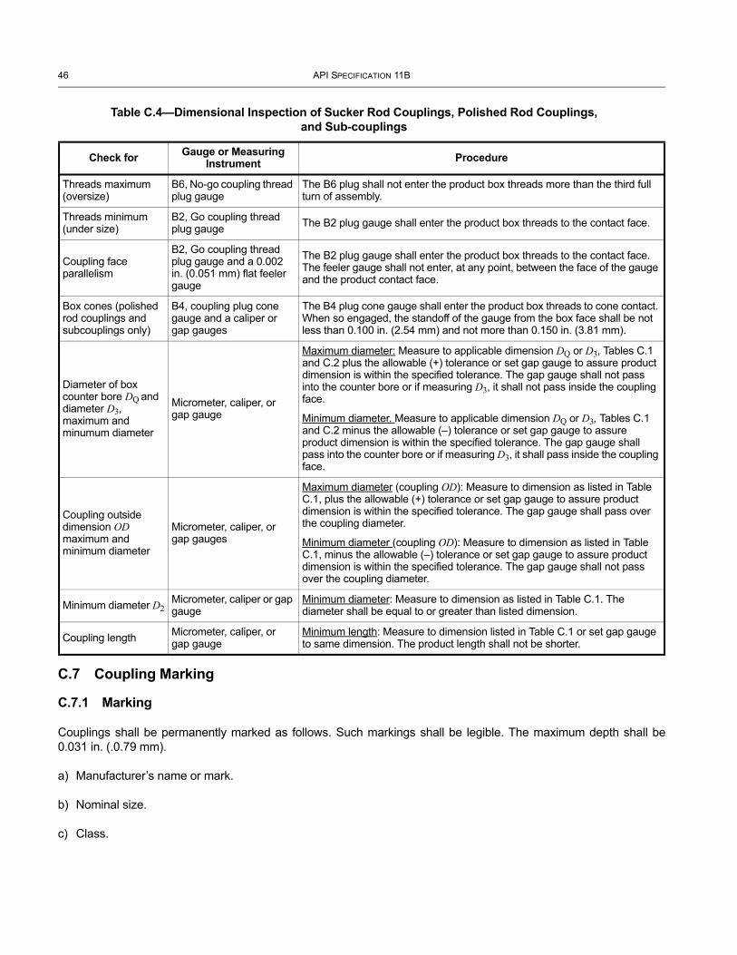
46 API SPECIFICATION 11B
C.7 Coupling Marking
C.7.1 Marking
Couplings shall be permanently marked as follows. Such markings shall be legible. The maximum depth shall be 0.031 in. (.0.79 mm).
a) Manufacturer’s name or mark.
b) Nominal size.
c) Class.
Table C.4—Dimensional Inspection of Sucker Rod Couplings, Polished Rod Couplings, and Sub-couplings
Check for Gauge or Measuring Instrument Procedure
Threads maximum (oversize)
B6, No-go coupling thread plug gauge
The B6 plug shall not enter the product box threads more than the third full turn of assembly.
Threads minimum (under size)
B2, Go coupling thread plug gauge The B2 plug gauge shall enter the product box threads to the contact face.
Coupling face parallelism
B2, Go coupling thread plug gauge and a 0.002 in. (0.051 mm) flat feeler gauge
The B2 plug gauge shall enter the product box threads to the contact face. The feeler gauge shall not enter, at any point, between the face of the gauge and the product contact face.
Box cones (polished rod couplings and subcouplings only)
B4, coupling plug cone gauge and a caliper or gap gauges
The B4 plug cone gauge shall enter the product box threads to cone contact. When so engaged, the standoff of the gauge from the box face shall be not less than 0.100 in. (2.54 mm) and not more than 0.150 in. (3.81 mm).
Diameter of box counter bore DQ and diameter D3, maximum and minumum diameter
Micrometer, caliper, or gap gauge
Maximum diameter: Measure to applicable dimension DQ or D3, Tables C.1 and C.2 plus the allowable (+) tolerance or set gap gauge to assure product dimension is within the specified tolerance. The gap gauge shall not pass into the counter bore or if measuring D3, it shall not pass inside the coupling face.
Minimum diameter. Measure to applicable dimension DQ or D3, Tables C.1 and C.2 minus the allowable (–) tolerance or set gap gauge to assure product dimension is within the specified tolerance. The gap gauge shall pass into the counter bore or if measuring D3, it shall pass inside the coupling face.
Coupling outside dimension OD maximum and minimum diameter
Micrometer, caliper, or gap gauges
Maximum diameter (coupling OD): Measure to dimension as listed in Table C.1, plus the allowable (+) tolerance or set gap gauge to assure product dimension is within the specified tolerance. The gap gauge shall pass over the coupling diameter.
Minimum diameter (coupling OD): Measure to dimension as listed in Table C.1, minus the allowable (–) tolerance or set gap gauge to assure product dimension is within the specified tolerance. The gap gauge shall not pass over the coupling diameter.
Minimum diameter D2Micrometer, caliper or gap gauge
Minimum diameter: Measure to dimension as listed in Table C.1. The diameter shall be equal to or greater than listed dimension.
Coupling length Micrometer, caliper, or gap gauge
Minimum length: Measure to dimension listed in Table C.1 or set gap gauge to same dimension. The product length shall not be shorter.
SPECIFICATION FOR SUCKER RODS, POLISHED RODS AND LINERS, COUPLINGS, SINKER BARS, POLISHED ROD CLAMPS, STUFFING BOXES, AND PUMPING TEES 47
d) Identification code. The code mark shall identify the product with respect to a record of the time of manufacture, grade of steel, heat number, and metallurgical treatment. This record shall be available to the user or purchaser on request for 5 years from date of manufacture.
e) The month of manufacture shall be designated by the numerals 01 through 12, chronologically, with January represented as number 01. Alternately, numerals 1 through 12 may be used.
f) The year of manufacture shall be designated by the last two numerals of the year.
EXAMPLE A Class T 3/4 in. nominal size, through hardened sucker rod coupling manufactured in April, 2009 and a sprayed metal sucker rod coupling manufactured in April, 2009 shall be marked as follows.
C.7.2 Polished Rod Couplings and Sub-couplings
In addition to the marking requirements for sucker rod couplings contained herein, polished rod couplings and sub-couplings shall be marked with the letters “PR” in front of the manufacturer’s name or mark.
EXAMPLE A 7/8 in. nominal size, class T polished rod coupling and a 3/4 in. × 7/8 in. nominal size sub-coupling manufactured in April, 2009 shall be marked as follows.
C.8 Ordering Information
Suggestions for ordering couplings and sub-couplings are as follows:
a) class;
b) type;
c) size;
d) quantity.
Manufacturer’s name or mark
Nominal size
Class Identification code Month Year
Class T coupling — 3/4 T — 04 09Class SM coupling — 3/4 SM — 04 09
Manufacturer's name or mark
Nominal size
Class Identification code Month Year
Polished Rod CouplingPR — 7/8 T — 04 09Sub-couplingPR — 3/4 x 7/8 T — 04 09
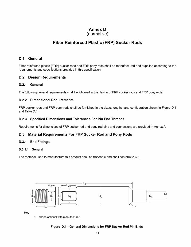
Annex D(normative)
Fiber Reinforced Plastic (FRP) Sucker Rods
D.1 General
Fiber reinforced plastic (FRP) sucker rods and FRP pony rods shall be manufactured and supplied according to the requirements and specifications provided in this specification.
D.2 Design Requirements
D.2.1 General
The following general requirements shall be followed in the design of FRP sucker rods and FRP pony rods.
D.2.2 Dimensional Requirements
FRP sucker rods and FRP pony rods shall be furnished in the sizes, lengths, and configuration shown in Figure D.1 and Table D.1.
D.2.3 Specified Dimensions and Tolerances For Pin End Threads
Requirements for dimensions of FRP sucker rod and pony rod pins and connections are provided in Annex A.
D.3 Material Requirements For FRP Sucker Rod and Pony Rods
D.3.1 End Fittings
D.3.1.1 General
The material used to manufacture this product shall be traceable and shall conform to 6.3.
DxWsD1DN DF
LwsLRLc
Ls 1
Du
Figure D.1—General Dimensions for FRP Sucker Rod Pin Ends
Key1 shape optional with manufacturer
48
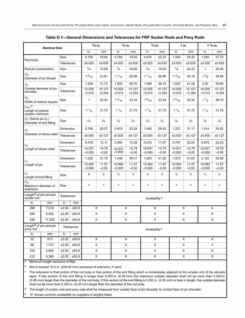
SPECIFICATION FOR SUCKER RODS, POLISHED RODS AND LINERS, COUPLINGS, SINKER BARS, POLISHED ROD CLAMPS, STUFFING BOXES, AND PUMPING TEES 49
Table D.1—General Dimensions and Tolerances for FRP Sucker Rods and Pony Rods
Nominal Size3/4 in. 3/4 in. 7/8 in. 1 in. 1 1/4 in.
in. mm in. mm in. mm in. mm in. mm
Rod bodySize 0.750 19.05 0.750 19.05 0.875 22.23 1.000 25.40 1.250 31.75
Tolerances ±0.025 ±0.635 ±0.025 ±0.635 ±0.025 ±0.635 ±0.025 ±0.635 ±0.025 ±0.635
Rod pin (connection) Size 5/8 15.88 3/4 19.05 3/4 19.05 7/8 22.23 1 25.40DNDiameter of pin thread Size 1 5/16 23.81 1 1/16 26.99 1 1/16 26.99 1 3/16 30.16 1 3/8 34.93
DFOutside diameter of pin shoulder
Size 1.250 31.75 1.500 38.10 1.500 38.10 1.625 41.28 2.00 50.80
Tolerances +0.005–0.010
+0.127–0.254
+0.005–0.010
+0.127–0.254
+0.005–0.010
+0.127–0.254
+0.005–0.010
+0.127–0.254
+0.005–0.010
+0.127–0.254
WSWidth of wrench square Size 1 25.40 1 5/16 33.34 1 5/16 33.34 1 5/16 33.34 1 1/2 38.10
LWS a
Length of wrench square, minimum
Size 1 1/4 31.75 1 1/4 31.75 1 1/4 31.75 1 1/4 31.75 1 1/4 31.75
DU (Same as DF )Diameter of end fitting Size DF DF DF DF DF DF DF DF DF DF
D1Diameter of stress relief
Dimension 0.790 20.07 0.915 23.24 1.040 26.42 1.227 31.17 1.414 35.92
Tolerances ±0.005 ±0.127 ±0.005 ±0.127 ±0.005 ±0.127 ±0.005 ±0.127 ±0.005 ±0.127
LRLength of stress relief
Dimension 0.516 13.11 0.594 15.09 0.672 17.07 0.797 20.24 0.875 22.23
Tolerances +0.031–0.000
+0.79–0.00
+0.031–0.000
+0.79–0.00
+0.031–0.000
+0.79–0.00
+0.031–0.000
+0.79–0.00
+0.031–0.000
+0.79–0.00
LSLength of pin
Dimension 1.250 31.75 1.438 36.51 1.625 41.28 1.875 47.63 2.125 53.98
Tolerances +0.062–0.000
+1.57–0.00
+0.062–0.000
+1.57–0.00
+0.062–0.000
+1.57–0.00
+0.062–0.000
+1.57–0.00
+0.062–0.000
+1.57–0.00
LCLength of end fitting Size b b b b b b b b b b
DXMaximum diameter of extension
Size c c c c c c c c c c
Lengthd of pin-and-pin sucker rod Tolerances
Availability e
in. mm in. mm296 7,518 ±2.00 ±50.8 X X X X X
356 9,042 ±2.00 ±50.8 X X X X X
446 11,328 ±2.00 ±50.8 X X X X X
Lengthd of pin-and-pin pony rod Tolerances
Availability e
in. mm in. mm32 813 ±2.00 ±50.8 X X X X X
68 1,727 ±2.00 ±50.8 X X X X X
104 2,642 ±2.00 ±50.8 X X X X X
212 5,385 ±2.00 ±50.8 X X X X Xa Minimum length exclusive of fillet.b Not to exceed 10.0 in. (254.00 mm) exclusive of extension, if used.c The extension is that portion of the rod body or that portion of the end fitting which is immediately adjacent to the smaller end of the elevator
taper. If this section of the end fitting is longer than 0.250 in. (6.35 mm) the maximum outside diameter shall not be more than 0.200 in. (5.08 mm) larger than the diameter of the rod body. If this section of the end fitting is 0.250 in. (6.35 mm) or less in length, the outside diameter shall not be more than 0.250 in. (6.35 mm) larger than the diameter of the rod body.
d The length of sucker rods and pony rods shall be measured from contact face of pin shoulder to contact face of pin shoulder.e “X” shows common availability by suppliers in lengths listed.
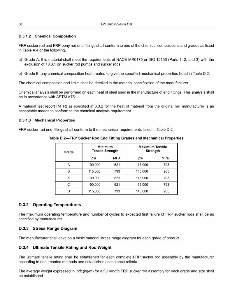
50 API SPECIFICATION 11B
D.3.1.2 Chemical Composition
FRP sucker rod and FRP pony rod end fittings shall conform to one of the chemical compositions and grades as listed in Table A.4 or the following.
a) Grade A: this material shall meet the requirements of NACE MR0175 or ISO 15156 (Parts 1, 2, and 3) with the exclusion of 10.3.1 on sucker rod pumps and sucker rods.
b) Grade B: any chemical composition heat treated to give the specified mechanical properties listed in Table D.2.
The chemical composition and limits shall be detailed in the material specification of the manufacturer.
Chemical analysis shall be performed on each heat of steel used in the manufacture of end fittings. This analysis shall be in accordance with ASTM A751.
A material test report (MTR) as specified in 6.3.2 for the heat of material from the original mill manufacturer is an acceptable means to conform to the chemical analysis requirement.
D.3.1.3 Mechanical Properties
FRP sucker rod end fittings shall conform to the mechanical requirements listed in Table D.2.
D.3.2 Operating Temperatures
The maximum operating temperature and number of cycles to expected first failure of FRP sucker rods shall be as specified by manufacturer.
D.3.3 Stress Range Diagram
The manufacturer shall develop a basic material stress range diagram for each grade of product.
D.3.4 Ultimate Tensile Rating and Rod Weight
The ultimate tensile rating shall be established for each complete FRP sucker rod assembly by the manufacturer according to documented methods and established acceptance criteria.
The average weight expressed in lb/ft (kg/m) for a full length FRP sucker rod assembly for each grade and size shall be established.
Table D.2—FRP Sucker Rod End Fitting Grades and Mechanical Properties
GradeMinimum
Tensile StrengthMaximum Tensile
Strength
psi MPa psi MPa
A 90,000 621 115,000 793
B 115,000 793 140,000 965
K 90,000 621 115,000 793
C 90,000 621 115,000 793
D 115,000 793 140,000 965
SPECIFICATION FOR SUCKER RODS, POLISHED RODS AND LINERS, COUPLINGS, SINKER BARS, POLISHED ROD CLAMPS, STUFFING BOXES, AND PUMPING TEES 51
D.4 Inspection and Testing
D.4.1 ASTM Testing
Manufacturers shall perform the following tests and verify conformance to the manufacturer’s documented specifications:
a) hardness in accordance with ASTM D2583;
b) ignition loss conforming to ASTM D2584;
c) horizontal shear strength as specified in ASTM D4475.
A minimum of two tests shall be performed on each manufacturing lot; one at the beginning and one at the end of the production run.
D.4.2 Proof Testing
FRP sucker rods shall be proof-tested to 110 % of their maximum working stress. This is to ensure seating of the end fitting and detection of defects in assembly. Each rod shall be inspected for visible evidence (visible pull out of the rod from the end fitting) after this proof test.
D.4.3 Re-testing
Lots failing to meet the test criteria may be reprocessed and considered acceptable if the test criteria are met when the lot is retested.
D.4.4 Inspection
FRP rods shall be checked for component length to ensure dimensional conformance. This addresses the rod socket depth dimension, which is to be inspected. Inspection of socket depth and rod body length will ensure dimensional conformance with respect to overall length.
D.5 Packaging
Spacers shall be provided such that rows of rod bodies do not touch during shipment.
Spacers and supports shall be provided along the bottom of each bundle such that the bundle can be lifted by straps placed at three points along the rod length. The support points shall be located within 1 ft (0.3 m) of center and at points no more than 6 ft (2 m) from each end.
Supports shall be provided along the bottom of each side of the bundle at the support points to prevent lifting straps from coming in contact with the bottom layer of rods.
Sufficient clearance shall be provided for passing lifting straps underneath the bundle at the support points without lifting or prying the bundle.
D.6 Thread Protectors
Thread protectors for FRP rods shall conform to A.9.
52 API SPECIFICATION 11B
D.7 Storage of FRP Rods
FRP rods shall be stored in accordance with A.10 and shall be protected from ultraviolet light according to manufacturer's recommendations.
D.8 Marking Requirements
FRP sucker rods shall be permanently marked on one or both ends as specified below. Such markings shall be legible. The maximum depth shall be 0.031 in. (0.79 mm). The following markings shall be applied to one or both ends. If applied to both ends, the marking on each end shall be complete.
a) Manufacturer’s name or mark.
b) Nominal rod body size and nominal connection size (see Table D.1).
c) Grade of end fitting (see Table D.2).
d) Month of manufacture: the month of manufacture shall be designated by the numerals 01 through 12, chronologically, with January represented as number 01. Alternately, the numerals may be 1 through 12.
e) The year of manufacture: the year of manufacture shall be designated by the last two numerals of the year.
EXAMPLE A 7/8 in. (22.23 mm) grade A FRP sucker rod with 3/4 in. (19.05 mm) sucker rod pins manufactured in February of 2009 shall be marked as follows:
D.9 Ordering Information
Suggestions for ordering FRP sucker rods and pony rods are as follows:
a) grade of end fittings;
b) nominal rod size (diameter);
c) connection nominal size;
d) length;
e) quantity;
f) packaging requirements.
Manufacturer’s name or mark
Size Grade Month Year
— 7/8 – 3/4 A 02 09

Annex E(normative)
Sinker Bars
E.1 General
Sinker bars shall be manufactured and supplied according to the requirements and specifications provided in this specification.
E.2 Design Requirements
E.2.1 Dimensional Requirements
Sinker bars shall be furnished in the sizes, lengths, and configuration shown in Figure E.1 and Table E.1, and with pin threads on each end. The pin threads may be either sucker rod pin threads or polished rod pin threads.
E.2.2 Dimensions and Tolerances for Sinker Bars
Sinker bars with sucker rod threads shall conform to all of the requirements of this specification for sucker rod threads.
Sinker bars with polished rod threads shall conform to all of the requirements of this specification for polished rod threads.
Polished rod couplings or sub-couplings shall be used on sinker bars with polished rod pin threads.
Polished rod couplings or sucker rod couplings may be used on sinker bars with sucker rod pin threads.
NOTE The use of sucker rod couplings on sinker bars with polished rod pins may result in premature failures, primarily as a result of split couplings.
Figure E.1—Sinker Bar Nomenclature
Key1 same thread detail both ends
2 Same flats detail both ends. Shape optional with manufacturer, two wrench flats standard, four flats optional
3 optional elevator neck, one end only
53
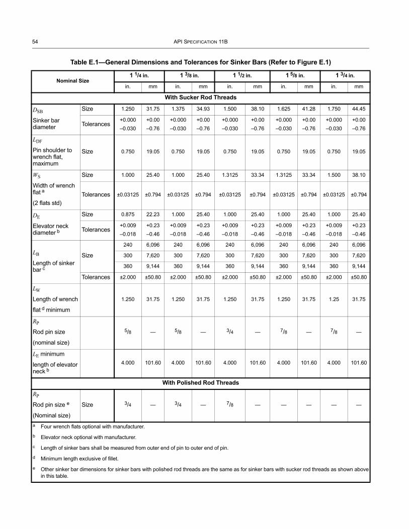
54 API SPECIFICATION 11B
Table E.1—General Dimensions and Tolerances for Sinker Bars (Refer to Figure E.1)
Nominal Size1 1/4 in. 1 3/8 in. 1 1/2 in. 1 5/8 in. 1 3/4 in.
in. mm in. mm in. mm in. mm in. mm
With Sucker Rod Threads
DSB
Sinker bar diameter
Size 1.250 31.75 1.375 34.93 1.500 38.10 1.625 41.28 1.750 44.45
Tolerances+0.000–0.030
+0.00–0.76
+0.000–0.030
+0.00–0.76
+0.000–0.030
+0.00–0.76
+0.000–0.030
+0.00–0.76
+0.000–0.030
+0.00–0.76
LDF
Pin shoulder to wrench flat, maximum
Size 0.750 19.05 0.750 19.05 0.750 19.05 0.750 19.05 0.750 19.05
WS
Width of wrench flat a
(2 flats std)
Size 1.000 25.40 1.000 25.40 1.3125 33.34 1.3125 33.34 1.500 38.10
Tolerances ±0.03125 ±0.794 ±0.03125 ±0.794 ±0.03125 ±0.794 ±0.03125 ±0.794 ±0.03125 ±0.794
DE
Elevator neck diameter b
Size 0.875 22.23 1.000 25.40 1.000 25.40 1.000 25.40 1.000 25.40
Tolerances+0.009–0.018
+0.23–0.46
+0.009–0.018
+0.23–0.46
+0.009–0.018
+0.23–0.46
+0.009–0.018
+0.23–0.46
+0.009–0.018
+0.23–0.46
LB
Length of sinker bar c
Size
240 6,096 240 6,096 240 6,096 240 6,096 240 6,096
300 7,620 300 7,620 300 7,620 300 7,620 300 7,620
360 9,144 360 9,144 360 9,144 360 9,144 360 9,144
Tolerances ±2.000 ±50.80 ±2.000 ±50.80 ±2.000 ±50.80 ±2.000 ±50.80 ±2.000 ±50.80
LW
Length of wrench
flat d minimum
1.250 31.75 1.250 31.75 1.250 31.75 1.250 31.75 1.25 31.75
RP
Rod pin size
(nominal size)
5/8 — 5/8 — 3/4 — 7/8 — 7/8 —
LE minimum
length of elevator neck b
4.000 101.60 4.000 101.60 4.000 101.60 4.000 101.60 4.000 101.60
With Polished Rod Threads
RP
Rod pin size e
(Nominal size)
Size 3/4 — 3/4 — 7/8 — — — — —
a Four wrench flats optional with manufacturer.
b Elevator neck optional with manufacturer.
c Length of sinker bars shall be measured from outer end of pin to outer end of pin.
d Minimum length exclusive of fillet.
e Other sinker bar dimensions for sinker bars with polished rod threads are the same as for sinker bars with sucker rod threads as shown above in this table.
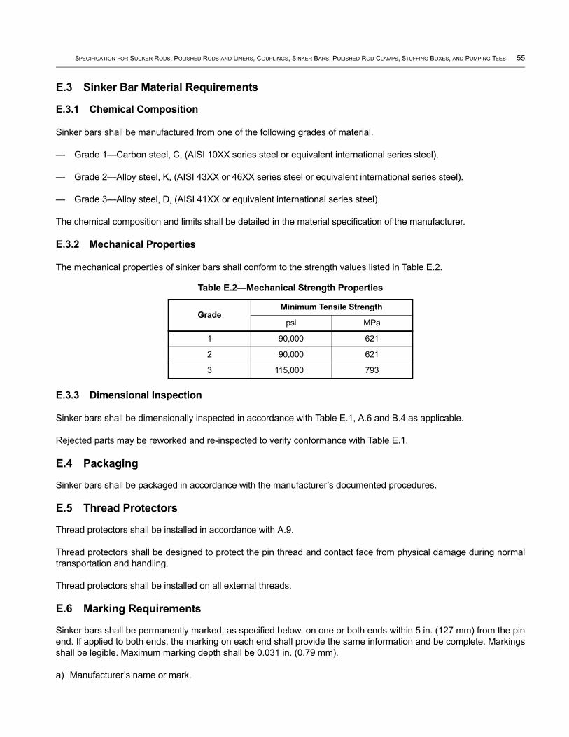
SPECIFICATION FOR SUCKER RODS, POLISHED RODS AND LINERS, COUPLINGS, SINKER BARS, POLISHED ROD CLAMPS, STUFFING BOXES, AND PUMPING TEES 55
E.3 Sinker Bar Material Requirements
E.3.1 Chemical Composition
Sinker bars shall be manufactured from one of the following grades of material.
— Grade 1—Carbon steel, C, (AISI 10XX series steel or equivalent international series steel).
— Grade 2—Alloy steel, K, (AISI 43XX or 46XX series steel or equivalent international series steel).
— Grade 3—Alloy steel, D, (AISI 41XX or equivalent international series steel).
The chemical composition and limits shall be detailed in the material specification of the manufacturer.
E.3.2 Mechanical Properties
The mechanical properties of sinker bars shall conform to the strength values listed in Table E.2.
E.3.3 Dimensional Inspection
Sinker bars shall be dimensionally inspected in accordance with Table E.1, A.6 and B.4 as applicable.
Rejected parts may be reworked and re-inspected to verify conformance with Table E.1.
E.4 Packaging
Sinker bars shall be packaged in accordance with the manufacturer’s documented procedures.
E.5 Thread Protectors
Thread protectors shall be installed in accordance with A.9.
Thread protectors shall be designed to protect the pin thread and contact face from physical damage during normal transportation and handling.
Thread protectors shall be installed on all external threads.
E.6 Marking Requirements
Sinker bars shall be permanently marked, as specified below, on one or both ends within 5 in. (127 mm) from the pin end. If applied to both ends, the marking on each end shall provide the same information and be complete. Markings shall be legible. Maximum marking depth shall be 0.031 in. (0.79 mm).
a) Manufacturer’s name or mark.
Table E.2—Mechanical Strength Properties
GradeMinimum Tensile Strength
psi MPa
1 90,000 621
2 90,000 621
3 115,000 793
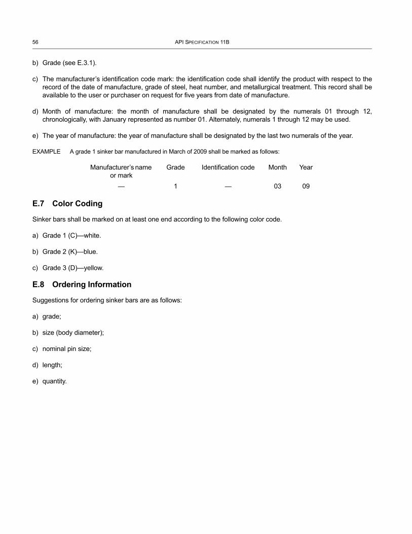
56 API SPECIFICATION 11B
b) Grade (see E.3.1).
c) The manufacturer’s identification code mark: the identification code shall identify the product with respect to the record of the date of manufacture, grade of steel, heat number, and metallurgical treatment. This record shall be available to the user or purchaser on request for five years from date of manufacture.
d) Month of manufacture: the month of manufacture shall be designated by the numerals 01 through 12, chronologically, with January represented as number 01. Alternately, numerals 1 through 12 may be used.
e) The year of manufacture: the year of manufacture shall be designated by the last two numerals of the year.
EXAMPLE A grade 1 sinker bar manufactured in March of 2009 shall be marked as follows:
E.7 Color Coding
Sinker bars shall be marked on at least one end according to the following color code.
a) Grade 1 (C)—white.
b) Grade 2 (K)—blue.
c) Grade 3 (D)—yellow.
E.8 Ordering Information
Suggestions for ordering sinker bars are as follows:
a) grade;
b) size (body diameter);
c) nominal pin size;
d) length;
e) quantity.
Manufacturer’s name or mark
Grade Identification code Month Year
— 1 — 03 09
Annex F(normative)
Polished Rod Clamps
F.1 General
Polished rod clamps shall be manufactured and supplied according to the requirements and specifications provided in this specification.
F.2 Design Requirements
F.2.1 General
The following requirements shall be followed in the design of polished rod clamps.
F.2.2 Dimensional Requirements
F.2.2.1 General
Polished rod clamps shall be furnished for the polished rod sizes listed in Table B.1.
F.2.2.2 Chemical Composition
To meet the requirements of this specification, polished rod clamps shall be manufactured from any AISI or equivalent specification recommended cast iron or carbon steel as follows.
a) ASTM A536 ductile iron 65-45-12, or equivalent international series number.
b) Carbon Steel: AISI 1015 to 1045 or AISI 1515 to 1545, or equivalent international series number.
F.2.2.3 Mechanical Properties
The allowable hardness range for polished rod clamps is between 190 and 300 HB.
F.2.2.4 Maximum Load Rating
Each polished rod clamp design shall have a stated maximum load rating. The maximum rated load shall be no more than 75 % of the minimum load to initial slippage when a new polished rod clamp which has successfully completed validation testing per F.3 in accordance with this specification.
F.3 Inspection and Testing
F.3.1 Design Validation Test
F.3.1.1 General
The manufacturer shall perform and document a minimum of two tests per polished rod clamp size and design by the method detailed herein to ensure that the polished rod clamp for each size will conform to the published rated loads.
Only new polished rod clamps shall be used in this test. A polished rod whose nominal diameter and surface finish conforms to this specification shall be used. The polished rod clamp shall be installed in accordance with the
57
58 API SPECIFICATION 11B
manufacturer’s instructions on one end of a sample of polished rod of suitable length that meets the rest of the requirements of this specification.
This test is considered non-destructive and any clamp passing this test is considered usable.
Validation test results shall be retained for a minimum of five years after production of that clamp size and design.
F.3.1.2 Validation Test Procedure
The validation test shall be conducted according to the following steps.
a) The polished rod sample shall be suspended by the polished rod clamp from the upper crosshead of a tensile testing machine through a hole in a steel plate. The dimension of the hole shall be the nominal diameter of the polished rod plus 0.125 in. (3.18 mm). The tolerances on the hole diameter shall be + 0.016 / – 0.000 in. (+ 0.41 / – 0.00 mm).
b) The polished rod shall be gripped in the lower crosshead and a load applied and increased until the first slippage of 0.010 in. (0.25 mm) or more occurs between the polished rod and the polished rod clamp. This load shall be recorded.
c) The rate of separation of the crossheads under load shall not exceed 0.500 in. (12.70 mm) per minute or be less than 0.125 in. (3.18 mm) per minute.
d) The minimum slippage load [see b) above] multiplied by 0.75 shall be equal to or greater than the published maximum rated load of the polished rod clamp.
F.3.1.3 Post Test Evaluation
Examination of the surface of the polished rod after the test and removal of the polished rod clamp shall not reveal any indentation or deformation in excess of 0.010 in. (0.25 mm). Failure to conform to this requirement shall constitute a test failure. If a test results in a failure, a successful new validation test is required prior to product production.
F.3.2 Functional Test
F.3.2.1 Performance
The manufacturer shall perform a production test on a clamp. The test procedure as detailed in F.3.1.2 shall be followed with the exception that F.3.1.2 b) be modified such that it is not necessary to load to slippage. The applied load shall be the maximum rated load.
F.3.2.2 Post Test Evaluation
If the clamp slips before reaching this load, production of that clamp shall immediately be stopped and corrective measures applied. A successful retest shall be achieved prior to resuming production of that clamp design.
F.4 Marking RequirementsEach polished rod clamp shall be permanently marked by the manufacturer with the following information.
a) Manufacturer’s name or mark.
b) Nominal polished rod size.
c) Maximum rated load.
SPECIFICATION FOR SUCKER RODS, POLISHED RODS AND LINERS, COUPLINGS, SINKER BARS, POLISHED ROD CLAMPS, STUFFING BOXES, AND PUMPING TEES 59
A tag showing the manufacturer’s installation instructions shall be securely attached (such as by wiring) to each polished rod clamp. This tag may be paper, plastic, or metal.
F.5 Ordering information
Suggestions for ordering polished rod clamps are as follows:
a) polished rod size;
b) load rating;
c) quantity.
Annex G(normative)
Stuffing Boxes
G.1 General
Stuffing boxes shall be designed, manufactured, and supplied according to the requirements and specifications provided in this specification.
G.2 Design Requirements
G.2.1 General
The following requirements shall be followed in the design of stuffing boxes. The stuffing box maximum working pressure shall be supplied by the manufacturer.
G.2.2 Dimensional Requirements
Stuffing boxes shall be furnished for the polished rod sizes listed in Table B.1 and polished rod liners listed in Table B.2.
Nominal thread connection size of stuffing boxes shall be in accordance with the size and type of bottom connection. The bottom connection shall be either upset or non-upset external tubing threads conforming to API 5B.
G.2.3 Chemical Composition
The chemical composition of stuffing boxes shall be any composition of AISI recommended series materials listed below which meet the mechanical property requirements. The chemical composition and limits shall be detailed in the material specification of the manufacturer.
a) ASTM A395 ductile iron, or equivalent international series number.
b) Carbon steel: AISI 1018 to 1045, or an equivalent international series number steel.
c) Alloy steel: AISI 4130 to 4140, or an equivalent international series number steel.
G.2.4 Material Requirements
The minimum material tensile strength shall be 60,000 psi (414 MPa) and the minimum material yield strength shall be 40,000 psi (276 MPa).
G.3 Inspection and Testing
G.3.1 Design Validation Test
Each stuffing box design shall be validated by a hydrostatic test to at least twice the manufacturer’s rated working pressure. The test shall be conducted according to the manufacturer’s written procedures including acceptance criteria. The test results shall be documented.
G.3.2 Thread Inspection
Production stuffing box threads shall be inspected in accordance with the manufacturer’s documented procedures and acceptance criteria.
60
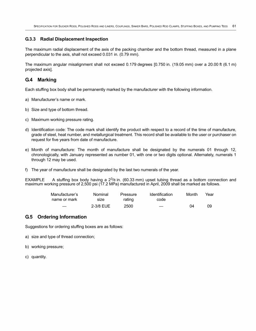
SPECIFICATION FOR SUCKER RODS, POLISHED RODS AND LINERS, COUPLINGS, SINKER BARS, POLISHED ROD CLAMPS, STUFFING BOXES, AND PUMPING TEES 61
G.3.3 Radial Displacement Inspection
The maximum radial displacement of the axis of the packing chamber and the bottom thread, measured in a plane perpendicular to the axis, shall not exceed 0.031 in. (0.79 mm).
The maximum angular misalignment shall not exceed 0.179 degrees [0.750 in. (19.05 mm) over a 20.00 ft (6.1 m) projected axis].
G.4 Marking
Each stuffing box body shall be permanently marked by the manufacturer with the following information.
a) Manufacturer’s name or mark.
b) Size and type of bottom thread.
c) Maximum working pressure rating.
d) Identification code: The code mark shall identify the product with respect to a record of the time of manufacture, grade of steel, heat number, and metallurgical treatment. This record shall be available to the user or purchaser on request for five years from date of manufacture.
e) Month of manufacture: The month of manufacture shall be designated by the numerals 01 through 12, chronologically, with January represented as number 01, with one or two digits optional. Alternately, numerals 1 through 12 may be used.
f) The year of manufacture shall be designated by the last two numerals of the year.
EXAMPLE A stuffing box body having a 23/8 in. (60.33 mm) upset tubing thread as a bottom connection and maximum working pressure of 2,500 psi (17.2 MPa) manufactured in April, 2009 shall be marked as follows.
G.5 Ordering Information
Suggestions for ordering stuffing boxes are as follows:
a) size and type of thread connection;
b) working pressure;
c) quantity.
Manufacturer’s name or mark
Nominal size
Pressure rating
Identification code
Month Year
— 2-3/8 EUE 2500 — 04 09
Annex H(normative)
Pumping Tees
H.1 General
Pumping tees shall be designed, manufactured, and supplied according to the requirements and specifications provided in this specification.
H.2 Design Requirements
H.2.1 General
The following general requirements shall be followed in the design of pumping tees. The pumping tee maximum working pressure shall be supplied by the manufacturer.
H.2.2 Dimensional Requirements
Nominal size of pumping tees shall be in accordance with the size and type of top, bottom and flow line connections. Top and bottom connections shall be either upset or non-upset internal tubing threads conforming to API 5B. Flow line connections shall be line pipe threads conforming to API 5B. Bleeder outlet shall be 1 in. (25.4 mm) line pipe thread conforming to API 5B.
H.2.3 Chemical Composition
The chemical composition of pumping tees shall be any composition of AISI recommended series materials which meet the chemical and mechanical property requirements listed below. The chemical composition and limits shall be detailed in the material specification of the manufacturer.
a) ASTM A395 ductile iron, or equivalent international series number.
b) Carbon steel: AISI 1018 to 1045, or an equivalent international series number steel.
c) Alloy steel: AISI 4130 to 4140, or an equivalent international series number steel.
H.2.4 Material Mechanical Requirements
The minimum material tensile strength shall be 60,000 psi (414 MPa) and the minimum material yield strength shall be 40,000 psi (276 MPa).
H.3 Inspection and Testing
H.3.1 Design Validation Test
Each pumping tee design shall be validated by a hydrostatic test to at least twice the manufacturer’s rated working pressure. The test shall be conducted according to the manufacturer’s written procedures including acceptance criteria. The test results shall be documented.
H.3.2 Thread Inspection
Production pumping tee threads shall be inspected in accordance with the manufacturer’s documented procedures and acceptance criteria.
62
SPECIFICATION FOR SUCKER RODS, POLISHED RODS AND LINERS, COUPLINGS, SINKER BARS, POLISHED ROD CLAMPS, STUFFING BOXES, AND PUMPING TEES 63
H.3.3 Radial and Angular Misalignment Inspections
The maximum radial displacement of axes of pumping tees threads, measured in the plane of the tee face, shall not exceed 0.013 in. (0.33 mm).
The maximum angular misalignment shall not exceed 0.179° [0.750 in. per 20.00 ft (19.05 mm per 6.1 m) of projected axis].
H.4 Marking
Pumping tees shall be permanently marked by the manufacturer with the following information.
a) Manufacturer’s name or mark.
b) Size and type of top, bottom and flow line threads.
c) Maximum working pressure rating.
d) Identification code: the code mark shall identify the product with respect to a record of the time of manufacture, grade of steel, heat number, and metallurgical treatment. Documentation of this record shall be available to the user or purchaser on request for five years from date of manufacture.
e) Month of manufacture: the month of manufacture shall be designated by the numerals 01 through 12, chronologically, with January represented as number 01, with one or two digits optional.
f) The year of manufacture shall be designated by the last two numerals of the year.
EXAMPLE A pumping tee having a 23/8 in. (60.33 mm) upset tubing thread on top, a 27/8 in. (73.03 mm) non-upset tubing thread on bottom, a 2 in. (50.80 mm) line pipe flow line connection, and maximum working pressure of 5,000 psi (34 MPa) manufactured in April 2009, shall be marked as follows.
H.5 Ordering Information
Suggestions for ordering pumping tees are as follows:
a) size and type of connections;
b) working pressure;
c) quantity.
Manufacturer’s name or mark
Size ofthreads
Maximum pressure, psi
Identification code
Month Year
— 2-3/8 EUE x 2-7/8 NU x 2 LP
2500 — 04 09
Annex I(normative)
Thread Gauge Specification
I.1 General
Reference master thread gauges shall be used and calibrated according to the requirements and specifications provided in this specification.
This annex applies to all working thread gauges and reference master thread gauges as specified.
NOTE The basis sizes of thread elements of reference master gauges are identical with those of the product. Gauge tolerances encroach on the product tolerance; therefore, it is theoretically possible for one gauge to accept and another to reject a given product thread. For this reason, a product thread passing any certified reference master gauge shall be considered as within the product dimensions, provided such gauge is within the limits specified for used gauges. In case of dispute the owner of gauges in question shall furnish proof regarding compliance.
I.2 Sucker Rod Pin Connections
I.2.1 Go Pin-thread Truncated Setting Plug Gauge, P7—This gauge represents the maximum permissible pitch diameter of the pin thread. It is used 1) in setting the mating ring gauge P8 and the corresponding working ring gauge. 2) in checking the shoulder squareness of the working gauge, and 3) for detecting wear, I.6.
I.2.2 Go Pin-thread Ring Gauges, P8—This gauge mates with the P7 go pin-thread plug gauge. In case of dispute, this gauge may be used in gauging the product pin threads, but such use should be held to a minimum.
I.2.3 No-go Pin-thread truncated Setting Plug Gauge, P5*—This gauge represents the minimum permissible pitch diameter of the pin thread. It is used 1) in setting the mating ring gauge P6 and the corresponding working ring gauge and 2) for detecting wear, see I.6.
I.2.4 No-go Pin-thread Ring Gauge, P6*—This gauge mates with the P5 no-go pin-thread plug gauge. In cases of dispute, this gauge may be used in gauging the product pin threads, but such use should be held to a minimum.
* No-go pin-thread plug and ring gauges, P5 and P6 are used on both sucker rods and polished rods.
I.3 Box Connections
I.3.1 Go Box-thread Ring Gauge (Checking Ring), B1—This gauge represents the minimum permissible pitch diameter of the box thread. It is used in checking the B2 go box-thread plug gauge and the corresponding working gauge, also in checking the shoulder squareness of the working gauge.
I.3.2 Go Box-thread Plug Gauge, B2—Go box-thread plug gauge B2 is used on polished rod couplings and sub-couplings but does not check the 9° cone. This gauge mates with the B1 go box-thread ring gauge. In cases of dispute, this gauge may be used in gauging the product box threads, but such use should be held to a minimum.
I.3.3 Box-cone Ring Gauge Fitting Ring, B3—Go box-cone plug and ring gauge B3 and B4 are used on polished rod couplings and sub-couplings. Do not use on sucker rod coupling. This represents the basic box cone. It is used as the master in establishing the standoff of the mating B4 plug gauge and the corresponding working plug gauge.
I.3.4 Box-cone Plug Gauge, B4—Go box-cone plug and ring gauge B3 and B4 are used on polished rod couplings and sub-couplings. Do not use on sucker rod coupling. This gauge mates with the B3 box-cone ring gauge. In cases of dispute, it may be used in gauging the product box cone, but such use should be held to a minimum.
64

SPECIFICATION FOR SUCKER RODS, POLISHED RODS AND LINERS, COUPLINGS, SINKER BARS, POLISHED ROD CLAMPS, STUFFING BOXES, AND PUMPING TEES 65
I.3.5 No-go Box-thread Ring Gauge (Checking Ring), B5—No-go box-thread ring and plug gauge B5 and B6 are used on sucker rod coupling, polished rod coupling, and sub-coupling. This gauge represents the maximum permissible pitch diameter of the box thread. It is used in checking the mating plug gauge B6 and the corresponding working plug gauge.
I.3.6 No-go Box-thread Plug Gauge, B6—No-go box-thread ring and plug gauge B5 and B6 are used on sucker rod coupling, polished rod coupling, and sub-coupling. This gauge mates with the B5 no-go box-thread ring gauge. In cases of dispute, this gauge may be used in gauging the product box threads, but such use should be held to a minimum.
I.4 Polished Rod Pin Connections
I.4.1 Go Pin-thread Truncated Setting Plug Gauge, P1—This gauge represents the maximum permissible pitch diameter of the pin thread. It is used 1) in setting the mating ring gauge P2 and the corresponding working ring gauge, 2) in checking the shoulder squareness of the working gauge, and 3) for detecting wear, see I.6.
I.4.2 Go Pin-thread Ring Gauge, P2—P2 does not check 9° cone. This gauge mates with the P1 go pin-thread plug gauge. In case of dispute, this gauge may be used in gauging the product pin threads, but such use should be held to a minimum.
I.4.3 Pin-cone Plug Gauge (Fitting Plug), P3—This gauge represents the basic pin cone. It is used as the master in establishing the standoff of the mating P4 pin-cone ring gauge and the corresponding working ring gauge.
I.4.4 Pin-cone Ring Gauge, P4—This gauge mates with the P3 pin-cone plug gauge. In cases of dispute, it may be used in gauging the product pin cone, but such use should be held to a minimum.
I.4.5 No-go Pin-thread Truncated Setting Plug Gauge, P5*—This gauge represents the minimum permissible pitch diameter of the pin thread. It is used in setting the mating ring gauge P6 and the corresponding working ring gauge.
I.4.6 No-go Pin-thread ring Gauge, P6*—This gauge mates with the P5 no-go pin-thread gauge. In cases of dispute, this gauge may be used in gauging the product pin threads, but such use should be held to a minimum.
* No-go pin-thread plug and ring gauges, P5 and P6 are used on both sucker rods and polished rods.
I.5 Hardening Reference master gauges shall be hardened within the limits of Rockwell C 60-C 63 or equivalent hardness on a superficial scale. They shall be ground and lapped gauges, and shall conform to the dimensions and tolerances given in Table I.1 to Table I.8 and shall have been certified as required in I.16.
I.5.1 Taper
Pitch diameter taper of setting plug gauges (P1, P5, and P7) and thread plug gauges (B2 and B6) shall not exceed 0.00015 in. (0.0038 mm) over the length LTS. The permissible taper shall be back taper (larger diameter at entering end) and shall be confined within the pitch diameter limits.
I.5.2 Precision Centers
Go plug gauges (P1, P7, and B2) and cone plug gauges (P3 and B4) shall have precision centers to permit measurement of runout of shoulder face and eccentricity of cone.
I.5.3 Construction
Cone ring gauges used on polished rods only shall be of the solid type (non-adjustable). Go and no-go ring gauges may be either solid or adjustable.
66 API SPECIFICATION 11B
I.6 Shake Test
Go and no-go ring gauges shall be set with all ring gauge threads fully engaged with their mating set plugs.
The shake test shall be performed on the truncated portion of the set plug, with the ring gauge backed off two turns from any engagement with the full form portion of the set plug. For acceptance there shall be no perceptible shake. (Shake is perceptible movement of the gauge when rocked back and forth after engaging per this procedure.) This test for shake shall be made on the truncated portion of full and truncated setting plugs. An adjustable ring gauge may be set initially on either the full form or the truncated portion of the setting plug. When screwed onto the other portion of the setting plug there shall be only a slight change in fit if any. If there is perceptible shake or play in the looser fit, the ring gauge should be reconditioned to bring the gauge into tolerance.
I.7 Root Form
The minor diameter of thread plug gauges and setting plug gauges shall be cleared beyond a P/8 width of flat, either by an extrusion of the sides of the thread toward a sharp V or by an undercut to any dimension no wider than the width resulting from P/8 maximum width either side of centerline of the thread space.
The major diameter of go thread ring gauges shall be cleared by a clearance cut of substantially P/8 width and approximately central.
The root form of the go and no-go thread ring gauges shall be of sufficient depth to clear the maximum major diameter of the full form setting plug after the gauge has been properly set.
The major diameter of no-go thread ring gauges shall be cleared by a clearance cut of substantially P/4 width and approximately central.
I.8 Blunt Start
The partial threads of both ends of all gauges and the junction of the full and truncated portions of setting plugs shall be removed to a blunt start except at the entering end of P4 and B3 ring gauges and the counterbored end of P2, P8, and B1 ring gauges where a blunt start would be undesirable or impractical. Figure I.1, Figure I.2, Figure I.4, and Figure I.5 illustrate deviations from the blunt start.
I.9 Helix Angle
The helix angle correction shall be disregarded in all pitch diameter determinations.
I.10 Gauge Marking (by Manufacturer)
Certified reference master gauges shall be permanently marked by the gauge manufacturer with the markings given below. Plug gauges should preferably be marked on the body, although marking on the handle is acceptable on gauges in small sizes or when the handle is integral with the body. Any markings which are considered necessary by the gauge maker may be added. Unless otherwise stated, both plug and ring shall be marked as follows:
a) the gauge registration number;
b) the gauge symbol as given in I.2;
c) the nominal size of the rod;
d) the word 2A-PIN or 2B-BOX, as applicable;
e) the word GO or NO-GO or CONE as applicable;

SPECIFICATION FOR SUCKER RODS, POLISHED RODS AND LINERS, COUPLINGS, SINKER BARS, POLISHED ROD CLAMPS, STUFFING BOXES, AND PUMPING TEES 67
f) the gauge manufacturer’s name or identifying mark.
EXAMPLE A master go pin-thread plug gauge, for 3/4 in. sucker rod should be marked as follows:
Gauge registration number P7-3/4 2A-PIN-GO Mfrs. name or identifying mark
I.11 Certification Testing
All new and reconditioned reference master gauges shall be submitted for testing to one of the certifying agencies listed in I.16, within a period of two years, if an outside agency indicates on the test certificate that the gauges are approaching the specified limits of permissible wear.
I.12 Reinspection Line
Gauges submitted to a certifying or outside agency for retest shall be certified as satisfactory for continued use if they conform to the following requirements:
a) The pitch diameter of go and no-go plug gauges (P7, P5, B2, B6, and P1) shall be within the tolerance limits as specified in Table I.1, Table I.2, Table I.3, Table I.5, and Table I.6.
b) The minor diameter of go and no-go ring gauges (P8, P6, B1, B5, and P2) shall be within the tolerance limits as specified in Table I.1, Table I.2, Table I.3, Table I.5, and Table I.6.
c) The axial variation of shoulder face of go thread plug and ring gauges (P1, P2, P7, P8, B1, and B2) shall be within the limits shown in Table I.9.
d) Cone plug and ring gauges (P3, P4, B3, and B4) shall be checked for mating step value, which shall not vary by more than 0.0015 in. (0.038 mm) from the original value.
NOTE This is equivalent to a decrease in cone base diameter of 0.00047 in. (0.0019 mm) on plug, or to an increase of 0.00047 in. (0.119 mm) on ring, or to a combined change of 0.00047 in. (0.0119 mm).
e) The fit of go and no-go thread gauges on their mating gauges shall conform to the requirements specified in I.6.
I.13 Maintenance
Maintenance of gauges is the responsibility of the gauge owner, and gauges reported by the certifying or outside agency as in non-conformance with requirements should be promptly reconditioned or replaced, and resubmitted for test.
I.14 Gauges
I.14.1 Go Pin-thread Gauges
Go pin-thread gauges shall conform to the dimensions in Table I.1.
The P7 and P8 gauges are for undercut pins and were first required in the 14th Edition (1962).
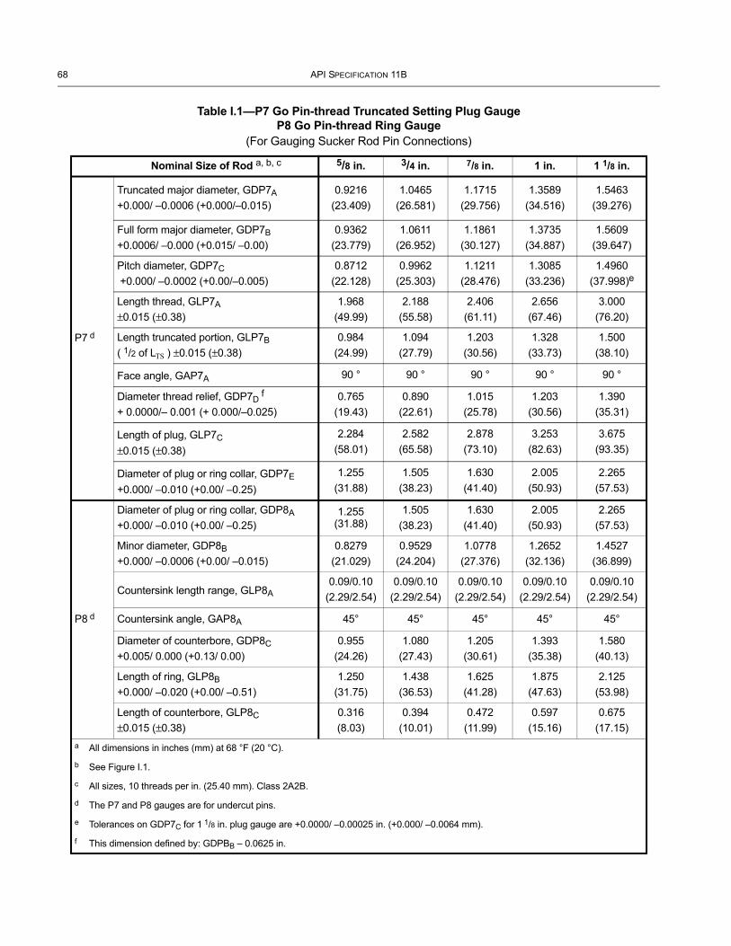
68 API SPECIFICATION 11B
Table I.1—P7 Go Pin-thread Truncated Setting Plug GaugeP8 Go Pin-thread Ring Gauge
(For Gauging Sucker Rod Pin Connections)
Nominal Size of Rod a, b, c 5/8 in. 3/4 in. 7/8 in. 1 in. 1 1/8 in.
P7 d
Truncated major diameter, GDP7A
+0.000/ –0.0006 (+0.000/–0.015)0.9216
(23.409)1.0465
(26.581)1.1715
(29.756)1.3589
(34.516)1.5463
(39.276)
Full form major diameter, GDP7B
+0.0006/ –0.000 (+0.015/ –0.00)0.9362
(23.779)1.0611
(26.952)1.1861
(30.127)1.3735
(34.887)1.5609
(39.647)
Pitch diameter, GDP7C +0.000/ –0.0002 (+0.00/–0.005)
0.8712(22.128)
0.9962(25.303)
1.1211(28.476)
1.3085(33.236)
1.4960(37.998)e
Length thread, GLP7A
±0.015 (±0.38)1.968
(49.99)2.188
(55.58)2.406
(61.11)2.656
(67.46)3.000
(76.20)
Length truncated portion, GLP7B( 1/2 of LTS ) ±0.015 (±0.38)
0.984(24.99)
1.094(27.79)
1.203(30.56)
1.328(33.73)
1.500(38.10)
Face angle, GAP7A 90 ° 90 ° 90 ° 90 ° 90 °
Diameter thread relief, GDP7D f
+ 0.0000/– 0.001 (+ 0.000/–0.025)0.765
(19.43)0.890
(22.61)1.015
(25.78)1.203
(30.56)1.390
(35.31)
Length of plug, GLP7C±0.015 (±0.38)
2.284(58.01)
2.582(65.58)
2.878(73.10)
3.253(82.63)
3.675(93.35)
Diameter of plug or ring collar, GDP7E+0.000/ –0.010 (+0.00/ –0.25)
1.255(31.88)
1.505(38.23)
1.630(41.40)
2.005(50.93)
2.265(57.53)
P8 d
Diameter of plug or ring collar, GDP8A
+0.000/ –0.010 (+0.00/ –0.25)1.255
(31.88)1.505
(38.23)1.630
(41.40)2.005
(50.93)2.265
(57.53)
Minor diameter, GDP8B+0.000/ –0.0006 (+0.00/ –0.015)
0.8279(21.029)
0.9529(24.204)
1.0778(27.376)
1.2652(32.136)
1.4527(36.899)
Countersink length range, GLP8A0.09/0.10
(2.29/2.54)0.09/0.10
(2.29/2.54)0.09/0.10
(2.29/2.54)0.09/0.10
(2.29/2.54)0.09/0.10
(2.29/2.54)
Countersink angle, GAP8A 45° 45° 45° 45° 45°
Diameter of counterbore, GDP8C+0.005/ 0.000 (+0.13/ 0.00)
0.955(24.26)
1.080(27.43)
1.205(30.61)
1.393(35.38)
1.580(40.13)
Length of ring, GLP8B
+0.000/ –0.020 (+0.00/ –0.51)1.250
(31.75)1.438
(36.53)1.625
(41.28)1.875
(47.63)2.125
(53.98)
Length of counterbore, GLP8C±0.015 (±0.38)
0.316(8.03)
0.394(10.01)
0.472(11.99)
0.597(15.16)
0.675(17.15)
a All dimensions in inches (mm) at 68 °F (20 °C).
b See Figure I.1.
c All sizes, 10 threads per in. (25.40 mm). Class 2A2B.
d The P7 and P8 gauges are for undercut pins.
e Tolerances on GDP7C for 1 1/8 in. plug gauge are +0.0000/ –0.00025 in. (+0.000/ –0.0064 mm).
f This dimension defined by: GDPBB – 0.0625 in.

SPECIFICATION FOR SUCKER RODS, POLISHED RODS AND LINERS, COUPLINGS, SINKER BARS, POLISHED ROD CLAMPS, STUFFING BOXES, AND PUMPING TEES 69
P8
P7
GDP8B
GAP8A
GDP8A
GDP8C
GLP8A
GLP8CGLP8B
GDP7B
GDP7A
GDP7C
GLP7C
GAP7A
GDP7D GDP7E
GLP7A
GLP7B
Figure I.1—Go Pin-thread Gauges (For Gauging Sucker Rod Pin Connections)
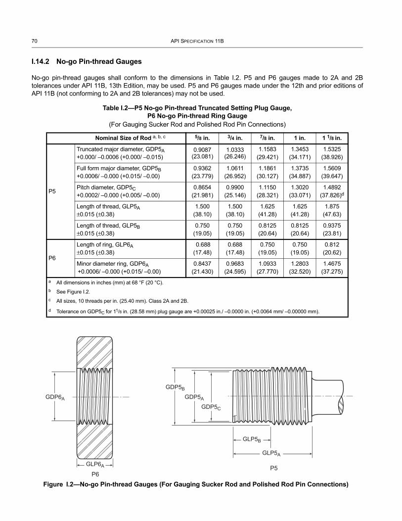
70 API SPECIFICATION 11B
I.14.2 No-go Pin-thread Gauges
No-go pin-thread gauges shall conform to the dimensions in Table I.2. P5 and P6 gauges made to 2A and 2B tolerances under API 11B, 13th Edition, may be used. P5 and P6 gauges made under the 12th and prior editions of API 11B (not conforming to 2A and 2B tolerances) may not be used.
Table I.2—P5 No-go Pin-thread Truncated Setting Plug Gauge,P6 No-go Pin-thread Ring Gauge
(For Gauging Sucker Rod and Polished Rod Pin Connections)
Nominal Size of Rod a, b, c 5/8 in. 3/4 in. 7/8 in. 1 in. 1 1/8 in.
P5
Truncated major diameter, GDP5A+0.000/ –0.0006 (+0.000/ –0.015)
0.9087 (23.081)
1.0333 (26.246)
1.1583(29.421)
1.3453(34.171)
1.5325(38.926)
Full form major diameter, GDP5B +0.0006/ –0.000 (+0.015/ –0.00)
0.9362(23.779)
1.0611(26.952)
1.1861(30.127)
1.3735(34.887)
1.5609(39.647)
Pitch diameter, GDP5C
+0.0002/ –0.000 (+0.005/ –0.00)0.8654
(21.981)0.9900
(25.146)1.1150
(28.321)1.3020
(33.071)1.4892
(37.826)d
Length of thread, GLP5A ±0.015 (±0.38)
1.500(38.10)
1.500(38.10)
1.625(41.28)
1.625(41.28)
1.875(47.63)
Length of thread, GLP5B ±0.015 (±0.38)
0.750(19.05)
0.750(19.05)
0.8125(20.64)
0.8125(20.64)
0.9375(23.81)
P6
Length of ring, GLP6A±0.015 (±0.38)
0.688(17.48)
0.688(17.48)
0.750(19.05)
0.750(19.05)
0.812(20.62)
Minor diameter ring, GDP6A +0.0006/ –0.000 (+0.015/ –0.00)
0.8437(21.430)
0.9683(24.595)
1.0933(27.770)
1.2803(32.520)
1.4675(37.275)
a All dimensions in inches (mm) at 68 °F (20 °C).b See Figure I.2.c All sizes, 10 threads per in. (25.40 mm). Class 2A and 2B.
d Tolerance on GDP5C for 11/8 in. (28.58 mm) plug gauge are +0.00025 in./ –0.0000 in. (+0.0064 mm/ –0.00000 mm).
P6P5
GDP6A
GLP6A
GDP5B
GDP5A
GDP5C
GLP5B
GLP5A
Figure I.2—No-go Pin-thread Gauges (For Gauging Sucker Rod and Polished Rod Pin Connections)
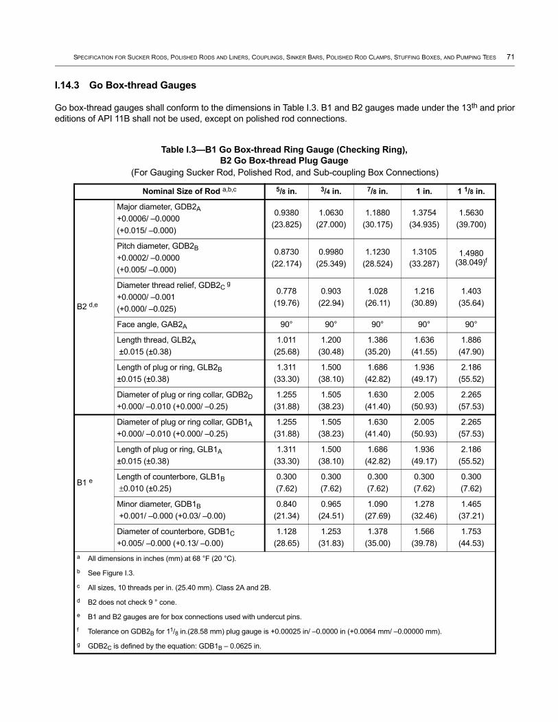
SPECIFICATION FOR SUCKER RODS, POLISHED RODS AND LINERS, COUPLINGS, SINKER BARS, POLISHED ROD CLAMPS, STUFFING BOXES, AND PUMPING TEES 71
I.14.3 Go Box-thread Gauges
Go box-thread gauges shall conform to the dimensions in Table I.3. B1 and B2 gauges made under the 13th and prior editions of API 11B shall not be used, except on polished rod connections.
Table I.3—B1 Go Box-thread Ring Gauge (Checking Ring), B2 Go Box-thread Plug Gauge
(For Gauging Sucker Rod, Polished Rod, and Sub-coupling Box Connections)
Nominal Size of Rod a,b,c 5/8 in. 3/4 in. 7/8 in. 1 in. 1 1/8 in.
B2 d,e
Major diameter, GDB2A+0.0006/ –0.0000(+0.015/ –0.000)
0.9380(23.825)
1.0630(27.000)
1.1880(30.175)
1.3754(34.935)
1.5630(39.700)
Pitch diameter, GDB2B+0.0002/ –0.0000(+0.005/ –0.000)
0.8730(22.174)
0.9980(25.349)
1.1230(28.524)
1.3105(33.287)
1.4980 (38.049)f
Diameter thread relief, GDB2C g
+0.0000/ –0.001(+0.000/ –0.025)
0.778(19.76)
0.903(22.94)
1.028(26.11)
1.216(30.89)
1.403(35.64)
Face angle, GAB2A 90° 90° 90° 90° 90°
Length thread, GLB2A ±0.015 (±0.38)
1.011(25.68)
1.200(30.48)
1.386(35.20)
1.636(41.55)
1.886(47.90)
Length of plug or ring, GLB2B±0.015 (±0.38)
1.311(33.30)
1.500(38.10)
1.686(42.82)
1.936(49.17)
2.186(55.52)
Diameter of plug or ring collar, GDB2D
+0.000/ –0.010 (+0.000/ –0.25)1.255
(31.88)1.505
(38.23)1.630
(41.40)2.005
(50.93)2.265
(57.53)
B1 e
Diameter of plug or ring collar, GDB1A+0.000/ –0.010 (+0.000/ –0.25)
1.255(31.88)
1.505(38.23)
1.630(41.40)
2.005(50.93)
2.265(57.53)
Length of plug or ring, GLB1A±0.015 (±0.38)
1.311(33.30)
1.500(38.10)
1.686(42.82)
1.936(49.17)
2.186(55.52)
Length of counterbore, GLB1B ±0.010 (±0.25)
0.300(7.62)
0.300(7.62)
0.300(7.62)
0.300(7.62)
0.300(7.62)
Minor diameter, GDB1B +0.001/ –0.000 (+0.03/ –0.00)
0.840(21.34)
0.965(24.51)
1.090(27.69)
1.278(32.46)
1.465(37.21)
Diameter of counterbore, GDB1C+0.005/ –0.000 (+0.13/ –0.00)
1.128(28.65)
1.253(31.83)
1.378(35.00)
1.566(39.78)
1.753(44.53)
a All dimensions in inches (mm) at 68 °F (20 °C).
b See Figure I.3.
c All sizes, 10 threads per in. (25.40 mm). Class 2A and 2B.
d B2 does not check 9 ° cone.
e B1 and B2 gauges are for box connections used with undercut pins.
f Tolerance on GDB2B for 11/8 in.(28.58 mm) plug gauge is +0.00025 in/ –0.0000 in (+0.0064 mm/ –0.00000 mm).
g GDB2C is defined by the equation: GDB1B – 0.0625 in.
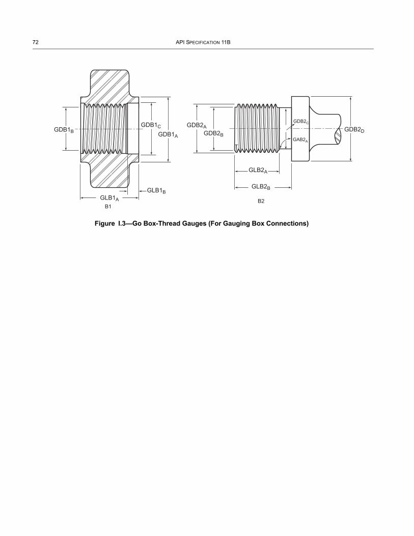
72 API SPECIFICATION 11B
B1B2
GDB1B
GLB1A
GLB1B
GDB1C
GDB1A
GDB2AGDB2B
GAB2A
GDB2C
GDB2D
GLB2A
GLB2B
Figure I.3—Go Box-Thread Gauges (For Gauging Box Connections)

SPECIFICATION FOR SUCKER RODS, POLISHED RODS AND LINERS, COUPLINGS, SINKER BARS, POLISHED ROD CLAMPS, STUFFING BOXES, AND PUMPING TEES 73
I.14.4 Box-cone Ring and Plug Gauges
Box-cone ring and plug gauges shall conform to the dimensions in Table I.4. B3 and B4 gauges made under any edition of API 11B may be used.
Table I.4—B3 Box-cone Ring Gauge (Fitting Ring), B4 Box-cone Plug Gauge
(For gauging polished rod and sub-coupling box connections.)
Nominal Size of Rod a, b, c 5/8 in. 3/4 in. 7/8 in. 1 in. 1 1/8 in.
B4 d
Major diameter, GDB4A+0.0006/–0.000 (+0.015/ –0.00)
0.9233(23.452)
1.0482(26.624)
1.1732(29.799)
1.3606(34.559)
1.5480(39.319)
Pitch diameter, GDB4B+0.0005/–0.000 (+0.013/ –0.00)
0.8654(21.981)
0.9900(25.146)
1.1150(28.321)
1.3020(33.071)
1.4892(37.826)
Thread relief, GLB4A±0.010 (±0.25)
0.150(3.81)
0.150(3.81)
0.150(3.81)
0.150(3.81)
0.150(3.81)
Cone angle, GAB4A+10’ / –0.0’
9° 9° 9° 9° 9°
Face angle, GAB4B±5’
90° 90° 90° 90° 90°
Relief diameter, GDB4C e
+0.00/–0.001 (+0.00/ –0.025) 0.760 (19.30)
0.885(22.48)
1.010(25.65)
1.197(30.40)
1.384(35.15)
Land length, GLB4B±0.010 (±0.25)
0.325(8.26)
0.325(8.26)
0.325(8.26)
0.325(8.26)
0.325(8.26)
Length thread, GLB4C±0.015 (±0.38)
0.63(16.00)
0.88(22.35)
0.88(22.35)
1.26(32.00)
1.51(38.35)
Diameter of plug or ring collar, GDB4D+0.000/ –0.010 (+0.00/ –0.25)
1.255(31.88)
1.505(38.23)
1.630(41.40)
2.005(50.93)
2.265(57.53)
Diameter plug cone, GDB4E+0.000/ –0.0002 (+0.00/ –0.005)
0.9430(23.952)
1.0680(27.127)
1.1930(30.302)
1.3805(35.065)
1.5680(39.827)
Length of plug or ring, GLB4D±0.015 (±0.38)
1.03(26.2)
1.28(32.5)
1.28(32.5)
1.66(42.2)
1.91(48.5)
B3 d
Length of plug or ring, GLB3A±0.015 (±0.38)
1.03(26.2)
1.28(32.5)
1.28(32.5)
1.66(42.2)
1.91(48.5)
Diameter of ring cone, GDB3A d See note d See note d See note d See note d See note d
Diameter of plug or ring collar, GDB3B+0.000/ –0.010 (+0.00/ –0.25)
1.255(31.88)
1.505(38.23)
1.630(41.40)
2.005(50.93)
2.265(57.53)
Angle, GAB3A +0/ –10’ 9 ° 9 ° 9 ° 9 ° 9 °
Minor diameter, GDB3C+0.000/ –0.001 (+0.00/ –0.03)
0.822(20.88)
0.947(24.05)
1.072(27.23)
1.259(31.98)
1.446(36.73)
a All dimensions in inches (mm) at 68 °F (20 °C).b See Figure I.4.c All sizes, 10 threads per in. (25.40 mm). Class 2A and 2B.d Diameter of ring cone (dimension GDB3A)shall be such as to provide a standoff of 0.325 in. ±0.0015 in. (8.26 mm ±0.038 mm).e GDB4C is defined by the equation: GDB3C – 0.0625 in.

74 API SPECIFICATION 11B
GDB3B
GDB3A
GLB3A
B3
GLB4D
B4
GDB4A GDB4DGDB4BGDB3C
GLB4C
GAB4B
GAB3A
GLB4B
GDB4C
GLB4A
GAB4A
GDB4E
Figure I.4—Box-cone Gauges (For Gauging Box Connections)
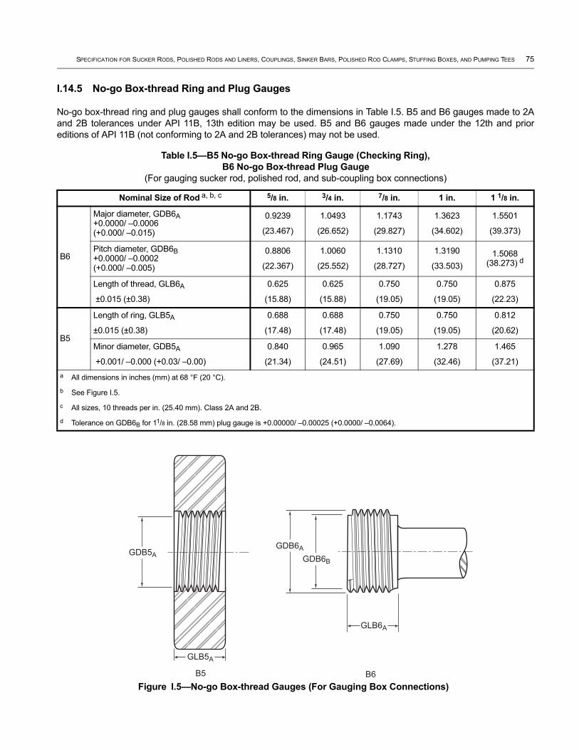
SPECIFICATION FOR SUCKER RODS, POLISHED RODS AND LINERS, COUPLINGS, SINKER BARS, POLISHED ROD CLAMPS, STUFFING BOXES, AND PUMPING TEES 75
I.14.5 No-go Box-thread Ring and Plug Gauges
No-go box-thread ring and plug gauges shall conform to the dimensions in Table I.5. B5 and B6 gauges made to 2A and 2B tolerances under API 11B, 13th edition may be used. B5 and B6 gauges made under the 12th and prior editions of API 11B (not conforming to 2A and 2B tolerances) may not be used.
Table I.5—B5 No-go Box-thread Ring Gauge (Checking Ring), B6 No-go Box-thread Plug Gauge
(For gauging sucker rod, polished rod, and sub-coupling box connections)
Nominal Size of Rod a, b, c 5/8 in. 3/4 in. 7/8 in. 1 in. 1 1/8 in.
B6
Major diameter, GDB6A +0.0000/ –0.0006 (+0.000/ –0.015)
0.9239
(23.467)
1.0493
(26.652)
1.1743
(29.827)
1.3623
(34.602)
1.5501
(39.373)
Pitch diameter, GDB6B +0.0000/ –0.0002 (+0.000/ –0.005)
0.8806
(22.367)
1.0060
(25.552)
1.1310
(28.727)
1.3190
(33.503)1.5068
(38.273) d
Length of thread, GLB6A
±0.015 (±0.38)
0.625
(15.88)
0.625
(15.88)
0.750
(19.05)
0.750
(19.05)
0.875
(22.23)
B5
Length of ring, GLB5A
±0.015 (±0.38)
0.688
(17.48)
0.688
(17.48)
0.750
(19.05)
0.750
(19.05)
0.812
(20.62)
Minor diameter, GDB5A
+0.001/ –0.000 (+0.03/ –0.00)
0.840
(21.34)
0.965
(24.51)
1.090
(27.69)
1.278
(32.46)
1.465
(37.21)a All dimensions in inches (mm) at 68 °F (20 °C).
b See Figure I.5.
c All sizes, 10 threads per in. (25.40 mm). Class 2A and 2B.
d Tolerance on GDB6B for 11/8 in. (28.58 mm) plug gauge is +0.00000/ –0.00025 (+0.0000/ –0.0064).
GLB5A
B5 B6
GDB6A
GDB6BGDB5A
GLB6A
Figure I.5—No-go Box-thread Gauges (For Gauging Box Connections)

76 API SPECIFICATION 11B
I.14.6 Go Pin-thread Truncated Setting Plug and Ring Gauges
Go pin-thread truncated setting plug and ring gauges shall conform to the dimensions in Table I.6. P1 and P2 gauges made to 2A and 2B tolerances under API 11B, 13th Edition, may be used. P1 and P2 gauges made under the 12th and prior editions of API 11B (not conforming to 2A and 2B tolerances) may not be used.
Table I.6—P1 Go Pin-thread Truncated Setting plug Gauge, P2 Go Pin-thread Ring Gauge(For gauging polished rod pin connections)
Nominal Size of Rod a, b, c 5/8 in. 3/4 in. 7/8 in. 1 in. 1 1/8 in.
P1
Truncated major diameter, GDP1A+0.0000/ –0.0006(+0.000/ –0.015)
0.9216(23.409)
1.0465(26.581)
1.1715(29.756)
1.3589(34.516)
1.5463(39.276)
Full form major diameter, GDP1B+0.0006/ –0.0000(+0.015/ –0.000)
0.9362(23.779)
1.0611(26.952)
1.1861(30.127)
1.3735(34.887)
1.5609(39.647)
Length of truncated portion, GLP1A(1/2 of LTS) ± 0.015 (±0.38)
0.625(15.88)
0.875(22.23)
0.875(22.23)
1.250(31.75)
1.500(38.10)
Face angle, GAP1A±5’ 90° 90° 90° 90° 90°
Relief diameter, GDP1C e
+0.000/ –0.001 (+0.000/ – 0.025)0.765
(19.43)0.890
(22.61)1.015
(25.78)1.203
(30.56)1.390
(35.31)
Pitch diameter, GDP1D+0.0000/ –0.0002 (+0.000/ –0.005)
0.8712(22.128)
0.9962(25.303)
1.1211(28.476)
1.3085(33.236)
1.4960(37.998)d
Length thread, GLP1B±0.015 (±0.38)
1.250(31.75)
1.750(44.45)
1.750(44.45)
2.500(63.50)
3.000(76.20)
Length of plug, GLP1C±0.015 (±0.38)
1.800(45.72)
2.300(58.42)
2.300(58.42)
3.050(77.47)
3.550(90.17)
Diameter of plug or ring collar, GDP1E+0.0000/ –0.0010 (+0.000/ –0.025)
1.255(31.88)
1.505(38.23)
1.630(41.40)
2.005(50.93)
2.265(57.53)
P2
Diameter of plug or ring collar, GDP2A+0.0000/ –0.0010 (+0.000/ –0.025)
1.255(31.88)
1.505(38.23)
1.630(41.40)
2.005(50.93)
2.265(57.53)
Minor diameter, GDP2B+0.0000/ –0.0006 (+0.000/ –0.015)
0.8279(21.029)
0.9529(24.204)
1.0778(27.376)
1.2652(32.136)
1.4527(36.899)
Chamfer angle, GAP2A±2 degrees 45° 45° 45° 45° 45°
Countersink depth range, GLP2A0.09/0.10
(2.29/2.54)0.09/0.10
(2.29/2.54)0.09/0.10
(2.29/2.54)0.09/0.10
(2.29/2.54)0.09/0.10
(2.29/2.54)
Length of counterbore, GLP2B±0.010 (±0.25)
0.550(13.97)
0.550(13.97)
0.550(13.97)
0.550(13.97)
0.550(13.97)
Diameter of counterbore, GDP2C+0.005/ –0.000 (+0.13/ –0.00)
0.955(24.26)
1.080(27.43)
1.205(30.61)
1.393(35.38)
1.580(40.13)
Length ring, GLP2C+0.000/ –0.020 (+0.00/ –0.51)
1.125(28.58)
1.375(34.93)
1.375(34.93)
1.750(44.45)
2.000(50.80)
a All dimensions in in. (mm) at 68 °F (20 °C).b See Figure I.6.c All sizes, 10 threads per in. (25.40 mm). Class 2A and 2B.d Tolerance on GDP1D for 11/8 in.(28.58 mm) plug gauge is +0.00000 in./ –0.00025 in. (+0.000 mm/ –0.0064 mm). e GDP1C is defined by the equation: GDP2B – 0.0625 in.

SPECIFICATION FOR SUCKER RODS, POLISHED RODS AND LINERS, COUPLINGS, SINKER BARS, POLISHED ROD CLAMPS, STUFFING BOXES, AND PUMPING TEES 77
GDP2C
P2 P1
GDP2A
GLP1C
GLP1A
GLP2B
GLP1B
GLP2C
GDP1EGDP2B
GAP2A
GLP2A
GDP1C
GAP1A
GDP1B
GDP1AGDP1D
Figure I.6—Go Pin-thread Gauges (For Gauging Polished Rod Pin Connections)
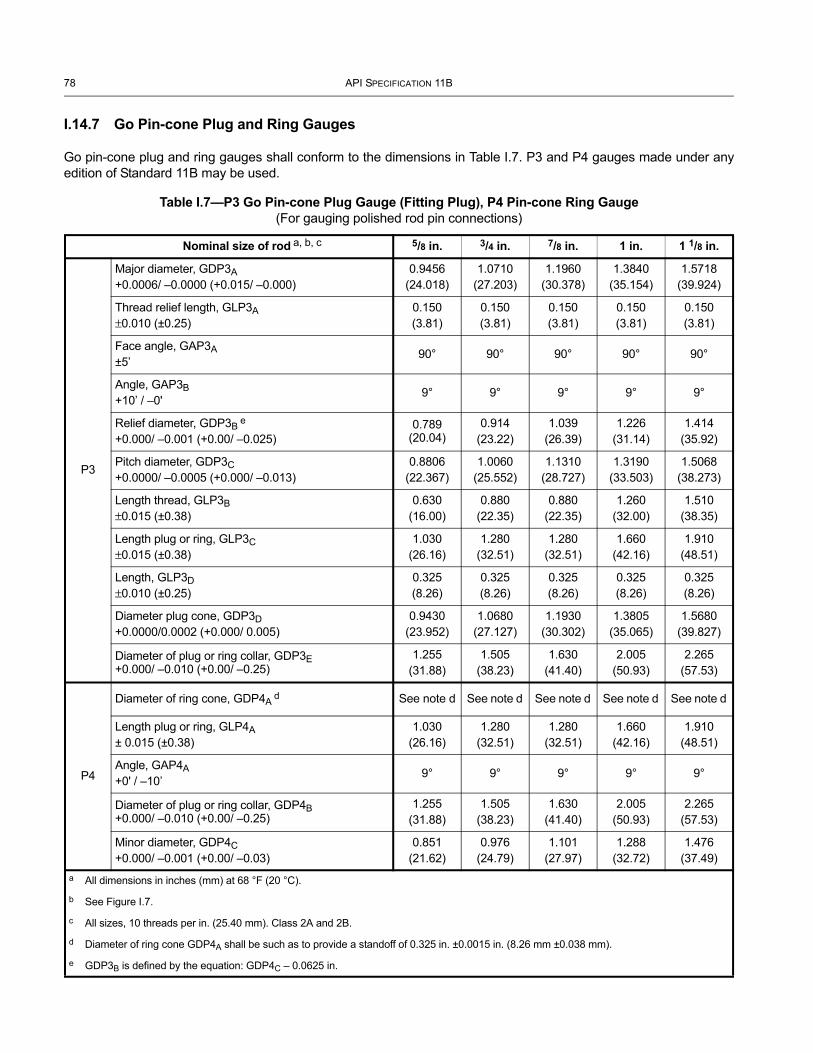
78 API SPECIFICATION 11B
I.14.7 Go Pin-cone Plug and Ring Gauges
Go pin-cone plug and ring gauges shall conform to the dimensions in Table I.7. P3 and P4 gauges made under any edition of Standard 11B may be used.
Table I.7—P3 Go Pin-cone Plug Gauge (Fitting Plug), P4 Pin-cone Ring Gauge(For gauging polished rod pin connections)
Nominal size of rod a, b, c 5/8 in. 3/4 in. 7/8 in. 1 in. 1 1/8 in.
P3
Major diameter, GDP3A+0.0006/ –0.0000 (+0.015/ –0.000)
0.9456(24.018)
1.0710(27.203)
1.1960(30.378)
1.3840(35.154)
1.5718(39.924)
Thread relief length, GLP3A±0.010 (±0.25)
0.150(3.81)
0.150(3.81)
0.150(3.81)
0.150(3.81)
0.150(3.81)
Face angle, GAP3A±5’
90° 90° 90° 90° 90°
Angle, GAP3B+10’ / –0'
9° 9° 9° 9° 9°
Relief diameter, GDP3B e +0.000/ –0.001 (+0.00/ –0.025)
0.789 (20.04)
0.914(23.22)
1.039(26.39)
1.226(31.14)
1.414(35.92)
Pitch diameter, GDP3C+0.0000/ –0.0005 (+0.000/ –0.013)
0.8806(22.367)
1.0060(25.552)
1.1310(28.727)
1.3190(33.503)
1.5068(38.273)
Length thread, GLP3B±0.015 (±0.38)
0.630(16.00)
0.880(22.35)
0.880(22.35)
1.260(32.00)
1.510(38.35)
Length plug or ring, GLP3C±0.015 (±0.38)
1.030(26.16)
1.280(32.51)
1.280(32.51)
1.660(42.16)
1.910(48.51)
Length, GLP3D±0.010 (±0.25)
0.325(8.26)
0.325(8.26)
0.325(8.26)
0.325(8.26)
0.325(8.26)
Diameter plug cone, GDP3D+0.0000/0.0002 (+0.000/ 0.005)
0.9430(23.952)
1.0680(27.127)
1.1930(30.302)
1.3805(35.065)
1.5680(39.827)
Diameter of plug or ring collar, GDP3E +0.000/ –0.010 (+0.00/ –0.25)
1.255(31.88)
1.505(38.23)
1.630(41.40)
2.005(50.93)
2.265(57.53)
P4
Diameter of ring cone, GDP4A d See note d See note d See note d See note d See note d
Length plug or ring, GLP4A± 0.015 (±0.38)
1.030(26.16)
1.280(32.51)
1.280(32.51)
1.660(42.16)
1.910(48.51)
Angle, GAP4A+0' / –10’
9° 9° 9° 9° 9°
Diameter of plug or ring collar, GDP4B +0.000/ –0.010 (+0.00/ –0.25)
1.255(31.88)
1.505(38.23)
1.630(41.40)
2.005(50.93)
2.265(57.53)
Minor diameter, GDP4C+0.000/ –0.001 (+0.00/ –0.03)
0.851(21.62)
0.976(24.79)
1.101(27.97)
1.288(32.72)
1.476(37.49)
a All dimensions in inches (mm) at 68 °F (20 °C).
b See Figure I.7.
c All sizes, 10 threads per in. (25.40 mm). Class 2A and 2B.
d Diameter of ring cone GDP4A shall be such as to provide a standoff of 0.325 in. ±0.0015 in. (8.26 mm ±0.038 mm).
e GDP3B is defined by the equation: GDP4C – 0.0625 in.
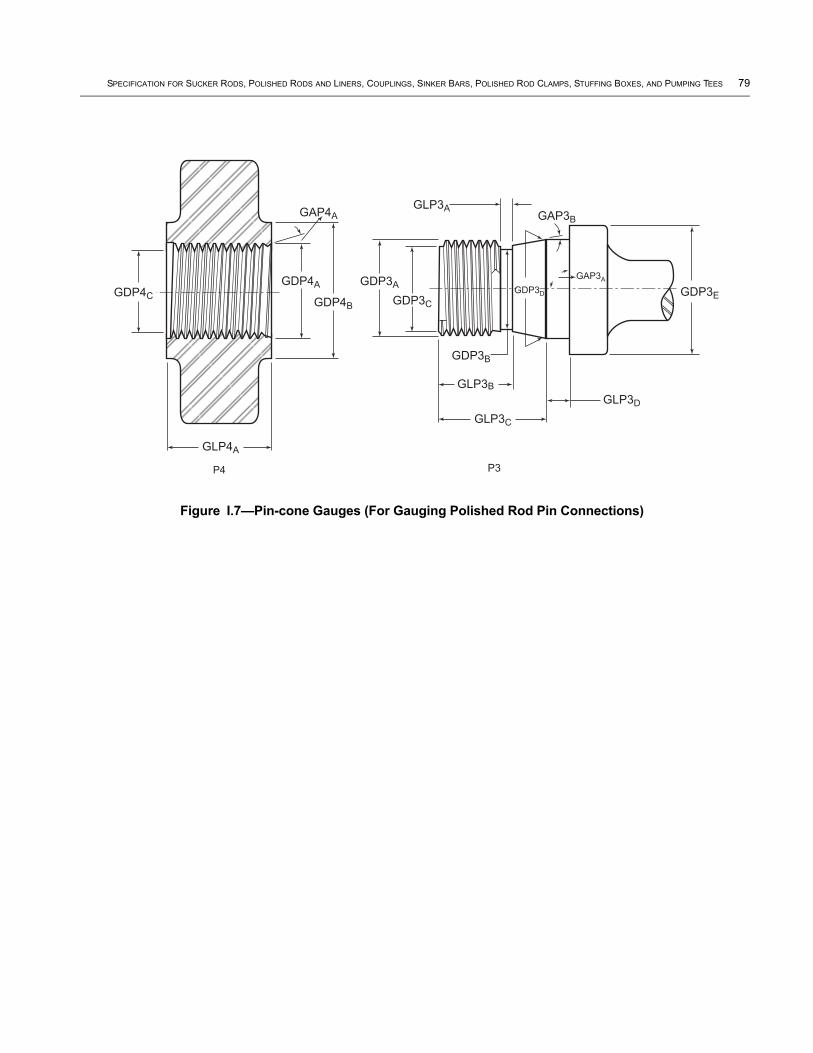
SPECIFICATION FOR SUCKER RODS, POLISHED RODS AND LINERS, COUPLINGS, SINKER BARS, POLISHED ROD CLAMPS, STUFFING BOXES, AND PUMPING TEES 79
P4 P3
GDP4A
GDP4B
GLP3C
GLP3D
GLP3B
GLP4A
GDP3A
GLP3A
GDP3EGDP3CGDP4C
GAP4A
GDP3B
GAP3A
GAP3B
GDP3D
Figure I.7—Pin-cone Gauges (For Gauging Polished Rod Pin Connections)
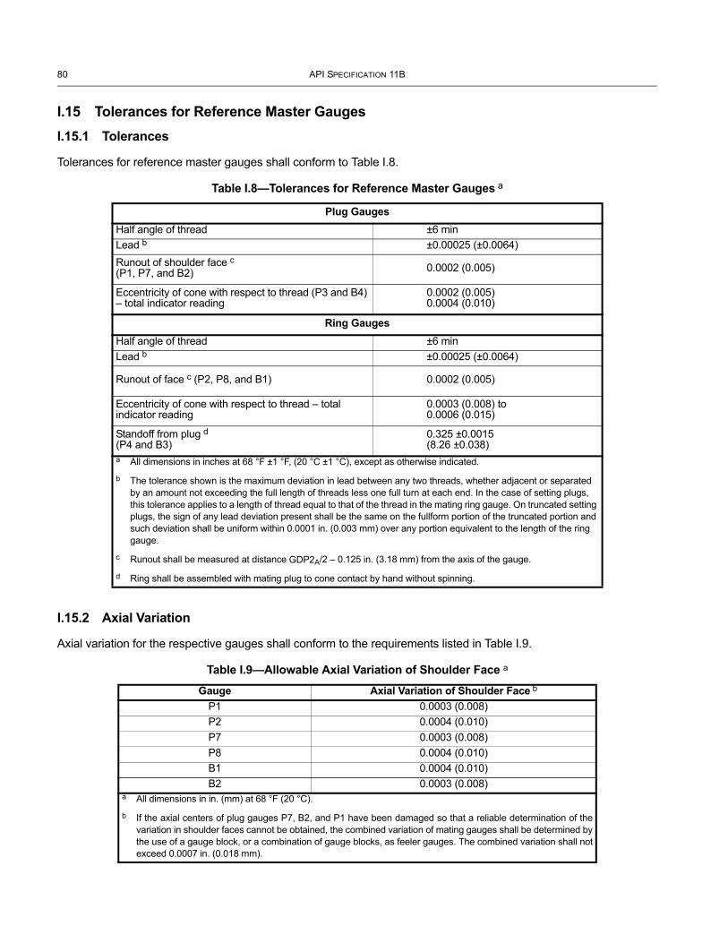
80 API SPECIFICATION 11B
I.15 Tolerances for Reference Master GaugesI.15.1 Tolerances
Tolerances for reference master gauges shall conform to Table I.8.
I.15.2 Axial Variation
Axial variation for the respective gauges shall conform to the requirements listed in Table I.9.
Table I.8—Tolerances for Reference Master Gauges a
Plug GaugesHalf angle of thread ±6 minLead b ±0.00025 (±0.0064)Runout of shoulder face c(P1, P7, and B2) 0.0002 (0.005)
Eccentricity of cone with respect to thread (P3 and B4) – total indicator reading
0.0002 (0.005) 0.0004 (0.010)
Ring GaugesHalf angle of thread ±6 minLead b ±0.00025 (±0.0064)
Runout of face c (P2, P8, and B1) 0.0002 (0.005)
Eccentricity of cone with respect to thread – total indicator reading
0.0003 (0.008) to 0.0006 (0.015)
Standoff from plug d(P4 and B3)
0.325 ±0.0015(8.26 ±0.038)
a All dimensions in inches at 68 °F ±1 °F, (20 °C ±1 °C), except as otherwise indicated.
b The tolerance shown is the maximum deviation in lead between any two threads, whether adjacent or separated by an amount not exceeding the full length of threads less one full turn at each end. In the case of setting plugs, this tolerance applies to a length of thread equal to that of the thread in the mating ring gauge. On truncated setting plugs, the sign of any lead deviation present shall be the same on the fullform portion of the truncated portion and such deviation shall be uniform within 0.0001 in. (0.003 mm) over any portion equivalent to the length of the ring gauge.
c Runout shall be measured at distance GDP2A/2 – 0.125 in. (3.18 mm) from the axis of the gauge.
d Ring shall be assembled with mating plug to cone contact by hand without spinning.
Table I.9—Allowable Axial Variation of Shoulder Face a
Gauge Axial Variation of Shoulder Face b
P1 0.0003 (0.008)P2 0.0004 (0.010)P7 0.0003 (0.008)P8 0.0004 (0.010)B1 0.0004 (0.010)B2 0.0003 (0.008)
a All dimensions in in. (mm) at 68 °F (20 °C).
b If the axial centers of plug gauges P7, B2, and P1 have been damaged so that a reliable determination of the variation in shoulder faces cannot be obtained, the combined variation of mating gauges shall be determined by the use of a gauge block, or a combination of gauge blocks, as feeler gauges. The combined variation shall not exceed 0.0007 in. (0.018 mm).

SPECIFICATION FOR SUCKER RODS, POLISHED RODS AND LINERS, COUPLINGS, SINKER BARS, POLISHED ROD CLAMPS, STUFFING BOXES, AND PUMPING TEES 81
I.16 Gauge Certification
I.16.1 Certification Agencies
All new and reconditioned reference master plug and mating ring gauges, prior to use, shall have been certified to be in conformance with the stipulations given in Annex I, by one of the following agencies.
NOTE A schedule of fees for tests be obtained upon application to the testing agency.
a) Instituto Nacional De Technologia Industrial, Buenos Aires, Argentina.
b) National Institute of Metrology, Beijing, People’s Republic of China.
c) National Institute of Standards and Technology, Gaithersburg, Maryland.
d) National Physical Laboratory, Teddington, Middlesex, England.
e) Oil Country Tubular Goods Inspection Laboratory.
f) China Natural Oil & Gas.
g) Exploration and Development Corporation BAOJI,SHAANXI People’s Republic of China.
h) Physikalisch-Technische Bundesanstalt, Braunschweig, Germany.
I.16.2 Certification
The gauge certifying agency shall inspect new and reconditioned reference master gauges for conformance to the requirements of Annex I. For each gauge which complies with all requirements, the certifying agency shall issue a certificate to the gauge owner, stating that the gauge complies with API 11B. For each gauge which does not conform to all requirements, the certifying agency shall issue a report to the gauge manufacturer stating the reason for rejection and showing the measured value for those dimensions which are outside the permissible limits. Reference master gauges must be certified in complete sets, i.e. a reference master plug and a reference master ring gauge. A single reference master plug or a single reference master ring gauge may not be certified unless accompanied by a previously certified mating reference master gauge.
I.16.3 Marking (by Certifying Agency)
The certifying agency shall verify the markings required under I.10, and shall mark all acceptable reference master gauges (both plug and ring unless otherwise stated below) with the markings as follows.
NOTE 1 The certifying agency may mark the gauges with any additional markings considered necessary for proper identification.
NOTE 2 In recertifying reconditioned gauges, the markings as applied by the certifying agency making the previous test shall be replaced as necessary, so that only one set of markings appears on the recertified gauge.
a) Date of Certification—The date of certification shall be marked on all gauges. In recertifying reconditioned gauges, the previous certification date shall be replaced with the date of recertification. Dates of retest, as required by I.11, shall not be marked on reference master gauges.
b) Name or Mark of Certifying Agency—The identification mark of the certifying agency shall be place on all gauges.
c) Mating Standoff—The initial mating standoff of cone gauges shall be marked on the ring gauge only for pin gauges, and on the plug gauge only for box gauges.

82 API SPECIFICATION 11B
I.16.4 Retest
On gauges submitted to the certifying agency for retest (see I.11 for test period), the agency shall give the owner a report, stating whether or not the gauge is suitable for further use, and if not, giving the measurements of the elements which are outside the permissible limits. If the gauge is approaching the permissible limit of wear and, in the opinion of the certifying agency, should be retested within a two-year period, the report shall so state, giving the measurement for the element or elements on which the statement is based.
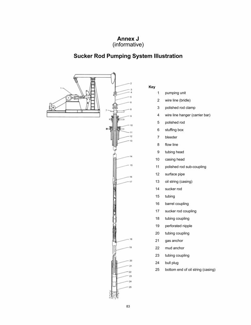
Annex J(informative)
Sucker Rod Pumping System Illustration
Key1 pumping unit
2 wire line (bridle)
3 polished rod clamp
4 wire line hanger (carrier bar)
5 polished rod
6 stuffing box
7 bleeder
8 flow line
9 tubing head
10 casing head
11 polished rod sub-coupling
12 surface pipe
13 oil string (casing)
14 sucker rod
15 tubing
16 barrel coupling
17 sucker rod coupling
18 tubing coupling
19 perforated nipple
20 tubing coupling
21 gas anchor
22 mud anchor
23 tubing coupling
24 bull plug
25 bottom end of oil string (casing)
83
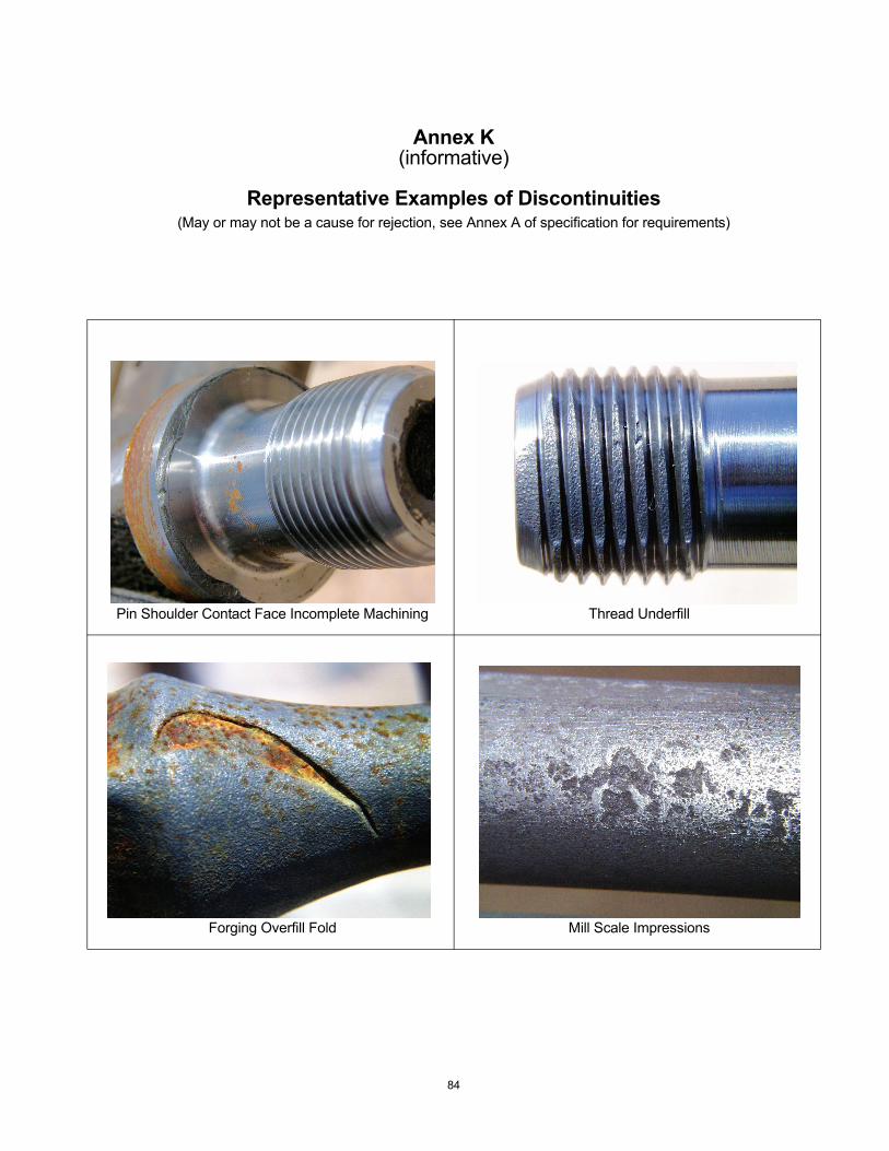
Annex K(informative)
Representative Examples of Discontinuities(May or may not be a cause for rejection, see Annex A of specification for requirements)
Pin Shoulder Contact Face Incomplete Machining Thread Underfill
Forging Overfill Fold Mill Scale Impressions
84
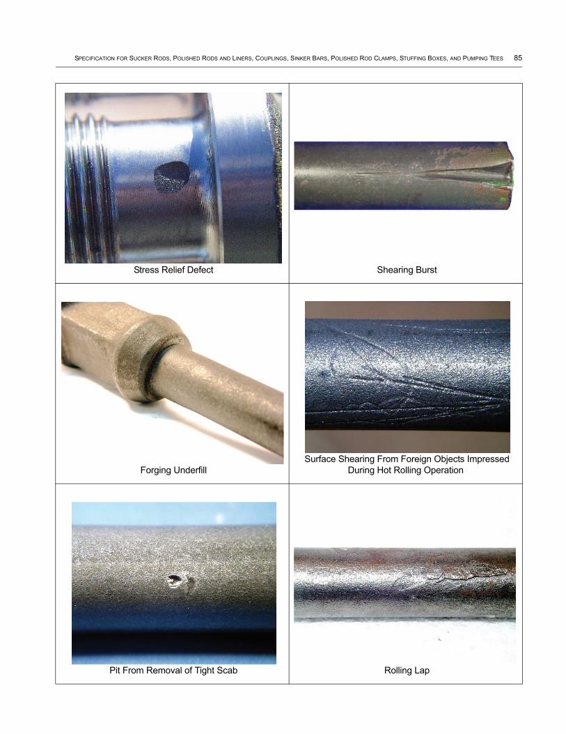
SPECIFICATION FOR SUCKER RODS, POLISHED RODS AND LINERS, COUPLINGS, SINKER BARS, POLISHED ROD CLAMPS, STUFFING BOXES, AND PUMPING TEES 85
Stress Relief Defect Shearing Burst
Forging Underfill Surface Shearing From Foreign Objects Impressed
During Hot Rolling Operation
Pit From Removal of Tight Scab Rolling Lap
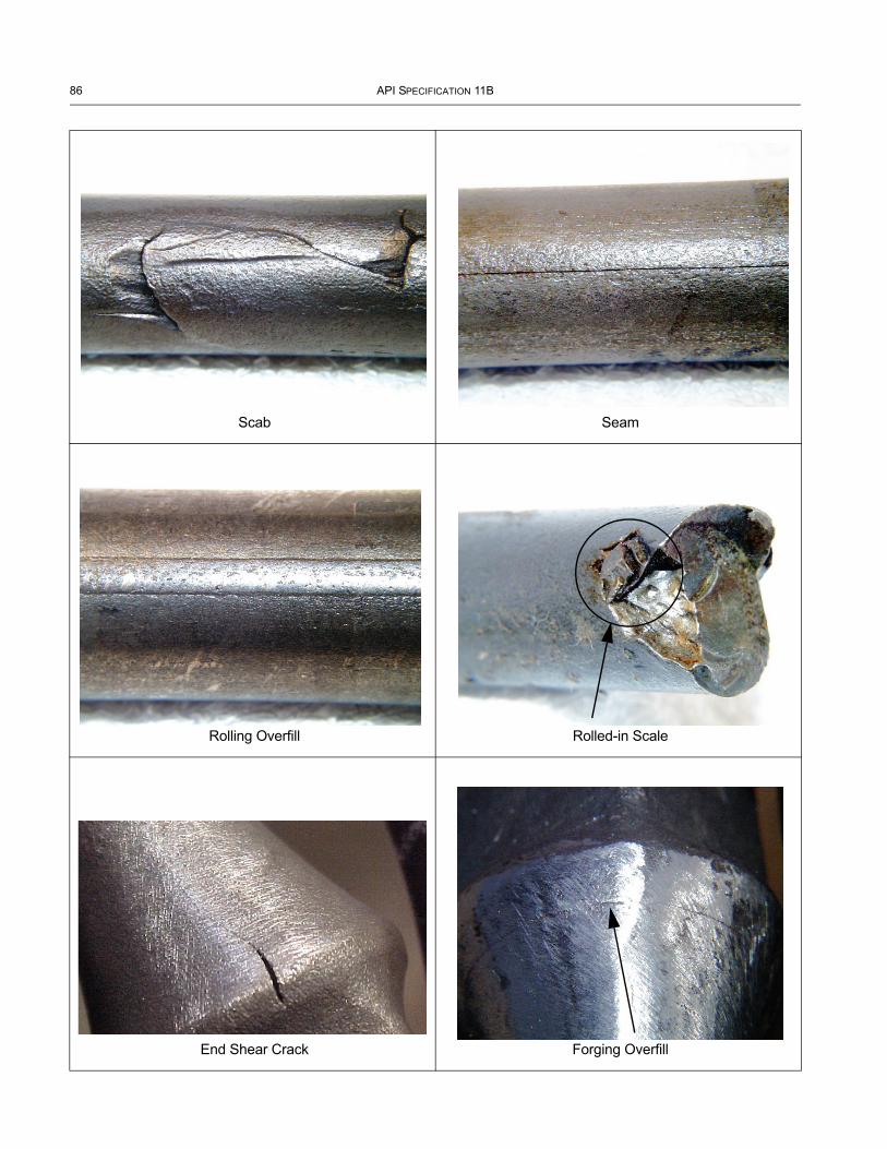
86 API SPECIFICATION 11B
Scab Seam
Rolling Overfill Rolled-in Scale
End Shear Crack Forging Overfill
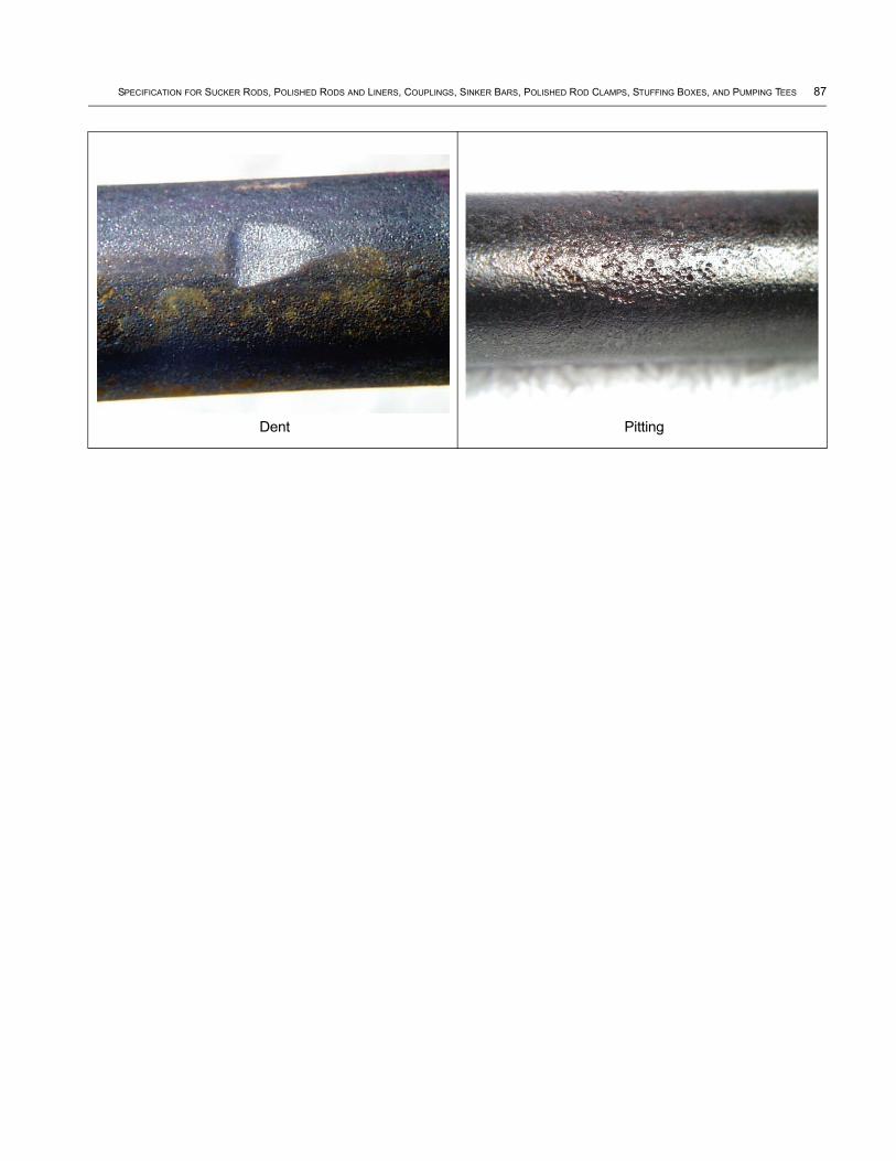
SPECIFICATION FOR SUCKER RODS, POLISHED RODS AND LINERS, COUPLINGS, SINKER BARS, POLISHED ROD CLAMPS, STUFFING BOXES, AND PUMPING TEES 87
Dent Pitting
Annex L(informative)
Use of the API Monogram By Licensees
L.1 Scope
The API Monogram Program allows an API Licensee to apply the API Monogram to products. The API Monogram Program delivers significant value to the international oil and gas industry by linking the verification of an organization’s quality management system with the demonstrated ability to meet specific product specification requirements. The use of the Monogram on products constitutes a representation and warranty by the Licensee to purchasers of the products that, on the date indicated, the products were produced in accordance with a verified quality management system and in accordance with an API product specification.
When used in conjunction with the requirements of the API License Agreement, API Specification Q1, in its entirety, defines the requirements for those organizations who wish to voluntarily obtain an API License to provide API monogrammed products in accordance with an API product specification.
API Monogram Program Licenses are issued only after an on-site audit has verified that the Licensee conforms to the requirements described in API Specification Q1 in total, and the requirements of an API product specification. Customers/Users are requested to report to API all problems with API monogrammed products. The effectiveness of the API Monogram Program can be strengthened by Customers/Users reporting problems encountered with API monogrammed products. A nonconformance may be reported using the API Nonconformance Reporting System available at https://ncr.api.org. API solicits information on new product that is found to be nonconforming with API specified requirements, as well as field failures (or malfunctions), which are judged to be caused by either specification deficiencies or nonconformities with API specified requirements.
This Annex sets forth the API Monogram Program requirements necessary for a supplier to consistently produce products in accordance with API specified requirements For information on becoming an API Monogram Licensee, please contact API, Certification Programs, 1220 L Street, N. W., Washington, DC 20005 or call 202-962-4791 or by email at [email protected].
L.2 References
In addition to the referenced standards listed earlier in this document, this Annex references the following standard:
API Specification Q1
For licensees under the Monogram Program, the latest version of this document shall be used. The requirements identified therein are mandatory.
L.3 API Monogram Program: Licensee Responsibilities
L.3.1 For all organizations desiring to acquire and maintain a license to use the API Monogram, conformance with the following shall be required at all times:
a) the quality management system requirements of API Specification Q1,
b) the API Monogram Program requirements of API Specification Q1, Annex A,
c) the requirements contained in the API product specification(s) for which the organization desires to be licensed,
d) the requirements contained in the API Monogram Program License Agreement.
88

SPECIFICATION FOR SUCKER RODS, POLISHED RODS AND LINERS, COUPLINGS, SINKER BARS, POLISHED ROD CLAMPS, STUFFING BOXES, AND PUMPING TEES 89
L.3.2 When an API Licensed organization is providing an API monogrammed product, conformance with API specified requirements, described in API Specification Q1, including Annex A, is required.
L.3.3 Each Licensee shall control the application of the API Monogram in accordance with the following:
a) Each Licensee shall develop and maintain an API Monogram Marking Procedure that documents the marking / monogramming requirements specified by the API product specification to be used for application of the API Monogram by the Licensee. The marking procedure shall define the location(s) where the Licensee shall apply the API Monogram and require that the Licensee’s license number and date of manufacture be marked on monogrammed products in conjunction with the API Monogram. At a minimum, the date of manufacture shall be two digits representing the month and two digits representing the year (e.g., 05-07 for May 2007) unless otherwise stipulated in the applicable API product specification. Where there are no API product specification marking requirements, the Licensee shall define the location(s) where this information is applied.
b) The API Monogram may be applied at any time appropriate during the production process but shall be removed in accordance with the Licensee’s API Monogram Marking Procedure if the product is subsequently found to be nonconforming with API specified requirements. Products that do not conform to API specified requirements shall not bear the API Monogram.
c) Only an API Licensee may apply the API Monogram and its license to API monogrammable products. For certain manufacturing processes or types of products, alternative Monogram marking procedures may be acceptable. The current API requirements for Monogram Marking are detailed in the API Policy Document, Monogram Marking Requirements, available on the API Monogram Program website at http://www.api.org/certifications/monogram/.
d) The API Monogram shall be applied at the licensed facility.
e) The authority responsible for applying and removing the API Monogram shall be defined in the Licensee’s API Monogram Marking Procedure.
L.3.4 Records required by API product specifications shall be retained for a minimum of five years or for the period of time specified within the product specification if greater than 5 years. Records specified to demonstrate achievement of the effective operation of the quality system shall be maintained for a minimum of 5 years.
L.3.5 Any proposed change to the Licensee’s quality program to a degree requiring changes to the quality manual shall be submitted to API for acceptance prior to incorporation into the Licensee’s quality program.
L.3.6 Licensee shall not use the API Monogram on letterheads or in any advertising (including company-sponsored web sites) without an express statement of fact describing the scope of Licensee’s authorization (license number). The Licensee should contact API for guidance on the use of the API Monogram other than on products.
L.4 Marking Requirements for Products
These marking requirements apply only to those API licensees wishing to mark their products with the API Monogram.
L.4.1 Manufacturers shall mark equipment on the nameplate with the information identified in the marking section of this specification, as a minimum, including “API 11B”.
L.4.2 As a minimum, equipment should be marked with English (Imperial) Units.
L.4.3 Nameplates, if required, shall be made of a corrosion-resistant material and shall be located as indication in the Marking section of this specification. If the location is not identified, then L.3.3.a shall apply.
90 API SPECIFICATION 11B
L.4.4 Nameplates may be attached at the point of manufacture or, at the option of the manufacturer, at the time of field erection.
L.4.5 The API Monogram shall be marked on the nameplate, in addition to the marking requirements of this specification. The API Monogram License number shall not be used unless it is marked in conjunction with the API Monogram.
L.5 API Monogram Program: API Responsibilities
L.5.1 The API shall maintain records of reported problems encountered with API monogrammed products. Documented cases of nonconformity with API specified requirements may be reason for an audit of the Licensee involved, (also known as Audit for “cause”).
L.5.2 Documented cases of specification deficiencies shall be reported, without reference to Licensees, Customers or Users, to API Subcommittee 18 (Quality) and to the applicable API Standards Subcommittee for corrective actions.
Bibliography
[1] API RP 11BR, Recommended Practice for Care and Handling of Sucker Rods
[2] ANSI/ASME 8 B1.2, Gauges and Gauging for Unified In Screw Threads
[3] ANSI/ASQC 9 Z1.4, Single Sampling Plan for Normal Inspection
[4] ASNT 10 SNT-TC-1A, Recommended Practice No. SNT-TC-1A Personnel Qualification and Certification in Nondestructive Testing
[5] ISO 11 9712, Non-destructive Testing — Qualification and Certification of Personnel
[6] ISO 11462-1, Guidelines for implementation of statistical process control (SPC) — Part 1: Elements of SPC
[7] ISO 11960, Petroleum and natural gas industries — Steel pipes for use as casing or tubing for wells
[8] NACE12 No. 1/SSPC-SP 5, Joint Surface Preparation Standard: White Metal Blast Cleaning
[9] SSPC 13, Surface Preparation Specification No. 11 (SSPC-SP 11): Power Tool Cleaning to Bare Metal
8 ASME International, 3 Park Avenue, New York, New York 10016, www.asme.org.9 American National Standards Institute, 25 West 43rd Street, 4th floor, New York, New York 10036, www.ansi.org.10 American Society for Nondestructive Testing, Inc., 1711 Arlingate Lane, P.O. Box 28518, Columbus, Ohio 43228,
www.asnt.org.11 International Organization for Standardization, 1, ch. de la Voie-Creuse, Case postale 56, CH-1211, Geneva 20, Switzerland,
www.iso.org.12 NACE International (formerly the National Association of Corrosion Engineers), 1440 South Creek Drive, Houston, Texas
77218-8340, www.nace.org.13 The Society for Protective Coatings, 40 24th Street, 6th Floor, Pittsburg, Pennsylvania 15222, www.sspc.org.
91


Invoice To (� Check here if same as “Ship To”)
Name:
Title:
Company:
Department:
Address:
City: State/Province:
Zip/Postal Code: Country:
Telephone:
Fax:
Email:
� Payment Enclosed � P.O. No. (Enclose Copy)
� Charge My IHS Account No.
� VISA � MasterCard � American Express� Diners Club � Discover
Credit Card No.:
Print Name (As It Appears on Card):
Expiration Date:
Signature:
Quantity Title Total
Subtotal
Applicable Sales Tax (see below)
Rush Shipping Fee (see below)
Shipping and Handling (see below)
Total (in U.S. Dollars)
� To be placed on Standing Order for future editions of thispublication, place a check mark in the SO column and sign here:
Date:
SO� Unit Price
� API Member (Check if Yes)
Ship To (UPS will not deliver to a P.O. Box)Name:
Title:
Company:
Department:
Address:
City: State/Province:
Zip/Postal Code: Country:
Telephone:
Fax:
Email:
Mail Orders – Payment by check or money order in U.S. dollars is required except for established accounts. State and local taxes, $10 processing fee, and 5% shipping must beadded. Send mail orders to: API Publications, IHS, 15 Inverness Way East, c/o Retail Sales, Englewood, CO 80112-5776, USA.Purchase Orders – Purchase orders are accepted from established accounts. Invoice will include actual freight cost, a $10 processing fee, plus state and local taxes.Telephone Orders – If ordering by telephone, a $10 processing fee and actual freight costs will be added to the order.Sales Tax – All U.S. purchases must include applicable state and local sales tax. Customers claiming tax-exempt status must provide IHS with a copy of their exemption certificate.Shipping (U.S. Orders) – Orders shipped within the U.S. are sent via traceable means. Most orders are shipped the same day. Subscription updates are sent by First-Class Mail.Other options, including next-day service, air service, and fax transmission are available at additional cost. Call 1-800-854-7179 for more information.
Shipping (International Orders) – Standard international shipping is by air express courier service. Subscription updates are sent by World Mail. Normal delivery is 3-4 days from shipping date.
Rush Shipping Fee – Next Day Delivery orders charge is $20 in addition to the carrier charges. Next Day Delivery orders must be placed by 2:00 p.m. MST to ensure overnight delivery.Returns – All returns must be pre-approved by calling the IHS Customer Service Department at 1-800-624-3974 for information and assistance. There may be a 15% restockingfee. Special order items, electronic documents, and age-dated materials are non-returnable.
Pricing and availability subject to change without notice.
2010 PUBLICATIONS ORDER FORM
Effective January 1, 2010. API Members receive a 30% discount where applicable. The member discount does not apply to purchases madefor the purpose of resale or for incorporation into commercial products, training courses, workshops, or other commercial enterprises.
Ordering Information Online: www.api.org/pubsPhone: 1-800-854-7179 (Toll-free in the U.S. and Canada) | (+1) 303-397-7956 (Local and International)Fax: (+1) 303-397-2740

THERE’S MOREWHERE THIS CAME FROM.
API Monogram® Licensing ProgramSales: (+1) 713-964-2662Service: (+1) 202-962-4791Fax: (+1) 202-682-8070Email: [email protected]: www.api.org/monogram
API Quality Registrar (APIQR®)• ISO 9001•ISO/TS 29001•ISO 14001•OHSAS 18001•API Spec Q1® •API QualityPlus®•Dual Registration Sales: (+1) 713-964-2662Service: (+1) 202-962-4791Fax: (+1) 202-682-8070Email: [email protected]: www.api.org/apiqr
API Individual Certification Programs (ICP®) Sales: (+1) 713-964-2662Service: (+1) 202-682-8064Fax: (+1) 202-682-8348Email: [email protected]: www.api.org/icp
API Engine Oil Licensing andCertification System (EOLCS)Sales: (+1) 713-964-2662Service: (+1) 202-682-8516Fax: (+1) 202-962-4739Email: [email protected]: www.api.org/eolcs
API Training Provider Certification Program (API TPCP™) Sales: (+1) 713-964-2662Service: (+1) 202-682-8075Fax: (+1) 202-682-8070Email: [email protected]: www.api.org/tpcp
API Perforator Design Registration ProgramSales: (+1) 713-964-2662Service: (+1) 202-682-8490Fax: (+1) 202-682-8070Email: [email protected]: www.api.org/perforators
API Credit Exchange (ACE™)Service: (+1) 202-682-8192Fax: (+1) 202-682-8070Email: [email protected]: www.api.org/ace
API Diesel Exhaust Fluid Certification Program Phone: (+1) 202-682-8516Fax: (+1) 202-962-4739Email: [email protected]: www.apidef.org
API WorkSafe™Sales: (+1) 713-964-2662 Service: (+1) 202-682-8469Fax: (+1) 202-682-8348Email: [email protected]: www.api.org/worksafe
API-UPhone: (+1) 202-682-8053Fax: (+1) 202-682-8070Email: [email protected]: www.api-u.org
API Data™Phone: (+1) 202-682-8499Fax: (+1) 202-962-4730Email: [email protected]: www.APIDataNow.org
API Publications Online: www.api.org/pubsPhone: 1-800-854-7179
(Toll-free: U.S./Canada)(+1) 303-397-7956 (Local/International)
Fax: (+1) 303-397-2740
API Standards Phone: (+1) 202-682-8148Fax: (+1) 202-962-4797Email: standards.orgWeb: www.api.org/standards
Request a Quotation:www.api.org/quote

Product No. G11B27