Embed Size (px)
Citation preview

研 究 報 告 書
東京工業高等専門学校
ISSN 0286-0503
第 44(1)号
2012.12
東京工業高等専門学校
研
究
報
告
書
第四十四(一)号
平成二十四年十二月
研 究 報 告 書
東京工業高等専門学校
ISSN 0286-0503
第 44(1)号
2012.12
東京工業高等専門学校
研
究
報
告
書
第四十四(一)号
平成二十四年十二月


東京工業高等専門学校研究報告書 第44(1)号 目次
「中国科学技術政策史」の試み(その2)………………………………………………… 河 村 豊…… 1
時間的余裕のない学習者のための外国語習得法に関する一考察 ― Part 4 : (18ヶ月間に亘る)基本文法習得に関して ―
…………………… ゲイツ ジョン…… 17
Q-Uを用いた学級集団の分析 …………………………………………………………… 黒 田 一 寿…… 23
Pump Performance and Flow Behavior in Valve Chamber according toChanges of Air Volume in Air Chamber in Water Hammer Pump System
………… 斉 藤 純 夫…… 33高 橋 正 旭永 田 佳 未岩 村 拓 哉出 嶌 京 太土 方 我 久
はんだの応力解析用構成モデルの調査と分類 ………………………………………… 林 丈 晴…… 57海老原 理 徳
ローラチェーンの三次元有限要素応力解析と引張強度向上のための提案 ………… 岩 元 翔 太…… 69志 村 穣黒 崎 茂
Evaluation for the Optimal Cylindrical Rod Position that effectson the Stall Control in a Thick Wind Turbine Blade
…………………… 斉 藤 純 夫…… 43山 科 貴 裕高 橋 正 旭岩 村 拓 哉大 沢 佳
ハプティックインタフェースを利用した生体シミュレータの基礎研究 ― 多自由度ペン型インタフェースの試作 ―
………… 多羅尾 進…… 77佐 藤 政 哉小 泉 岳 大齋 藤 浩 一
リフレッシュエアを周期的に導入する振動流による換気 …………………………… 清 水 昭 博…… 81佐 藤 正 樹清 水 優 史菅 原 路 子
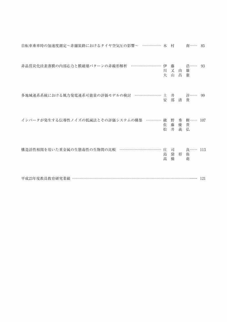
自転車乗車時の加速度測定~非舗装路におけるタイヤ空気圧の影響~ …………… 木 村 南…… 85
インバータが発生する伝導性ノイズの低減法とその評価システムの構築 ………… 綾 野 秀 樹…… 107佐 藤 優 貴松 井 義 弘
構造活性相関を用いた重金属の生態毒性の生物間の比較 …………………………… 庄 司 良…… 113島 袋 将 弥高 橋 萌
平成23年度教員教育研究業績 ……………………………………………………………………………………… …… 121
非晶質炭化珪素薄膜の内部応力と膜破壊パターンの非線形解析 …………………… 伊 藤 浩…… 93川 又 由 雄大 山 昌 憲
多地域連系系統における風力発電連系可能量の評価モデルの検討 ………………… 土 井 淳…… 99安 部 清 貴

Research Reports of Tokyo National College of Technology No. 44 (1)CONTENTS
Yutaka Kawamura …………… ……On the History of Science and Technology Policy in China, Part 2. 1
John Gates ……………………………………
Learning a Foreign Language from a Busy Person’s Perspective-Part 4: Grammar Foundation Completed after 18 Months- 17
Kazutoshi Kuroda …………… ………An analysis of class communities by using Questionnaire-Utilities 23
Sumio SaitoMasaaki TakahashiYoshimi NagataTakuya IwamuraKeita DejimaGaku Hijikata
………………………
Pump Performance and Flow Behavior in Valve Chamber according toChanges of Air Volume in Air Chamber in Water Hammer Pump System 33
Sumio SaitoTakahiro YamashinaMasaaki TakahashiTakuya IwamuraKai Osawa
……………………………………………
Evaluation for the Optimal Cylindrical Rod Position that effectson the Stall Control in a Thick Wind Turbine Blade 43
Shouta IwamotoJyo ShimuraShigeru Kurosaki
……………………………
Three-dimensional Finite Element Stress Analysis of Roller Chain andSome Design Proposals for Improvement of Tensile Strength 69
Susumu TaraoMasaya SatoTakehiro KoizumiHirokazu Saito
………………………………………
Basic Study of Biophysical Simulator Using a Haptic Interface-Prototyping for a Multi-DOF Pen -Style Interface- 77
Akihiro ShimizuMasaki SatoMasashi ShimizuMichiko Sugawara
…………………………………………………
Ventilation by Oscillatory Flowwith Cyclic Introduction of Refreshing Air 81
Takeharu HayashiYoshinori Ebihara
……………………………………………………………………
Survey and Classification of Constitutive Models Used forStress Analysis of Solder 57
Minami Kimura ……………… ……………Acceleration measurement of bicycle on non-pavement road 85
Hiroshi ItoYoshio KawamataMasanori Ohyama
………………………………………………
Nonlinear Analysis of Film Breakdown and Internal Stress of Amorphous Silicon Carbide Films 93
Hideki AyanoYuki SatoYoshihiro Matsui
……………………………
New Reduction Technique of a Conductive Noise Generated by an Inverter and Construction of the Measurement System 107
Ryo ShojiMasaya ShimabukuroMoe Takahashi
………………………
……………………
Analysis on toxicity of heavy metals against organismsin different stages in whole ecosystem byQSAR(Quantitative Structure Activity Relationship) 113
Atsushi DoiKiyotaka Abe
……………………………………
A Study of Evaluation Model for Allowable Capacity of Wind Power Generations in Multi-Area Interconnected Power System 99
2012 1-1-1
(A) Web
http://data.nistep.go.jp/dspace/bitstream/11035/1154/3/NISTEP-RM214-MaterialJ.pdf
43 2 2012 pp19-30.
47,(3/4) 1980 10 pp.287-317 p.107-
IC
On the History of Science and Technology Policy in China, Part .Yutaka KAWAMURA
This paper discusses the history of Science and Technology Policy in China from 1977 to 2007.After the reform and opening to the outside world in China, Deng Xiaoping who is the firstgeneration reader in Chinese socialist revolution made Law of the People's Republic of China onScience and Technology Progress at 1993. I pointed out the reason why he thought that scienceand technology is the “first forces of production and Chinese need reform and opening-up policyon the science and technology program, using the material The Speeches of Deng Xiaoping .
2012 20107,062
1987 74 10020 56
2.6 1.3OECD
2009
1980
1950 60
19702007
1960~701970
1970
1980
1960~70
43 2 2012 pp.19-30.
47,(3/4) 1980 10 pp.287-317 p.107-
IC
1東京工業高等専門学校研究報告書 第44(1)号,2012
This paper discusses the history of Science and Technology Policy in China from 1977 to 2007. After the reform and opening to the outside world in China, Deng Xiaoping who is the first generation reader in Chinese socialist revolution made Law of the People’s Republic of China on Science and Technology Progress at 1993. I pointed out the reason why he thought that science and technology is the“fi rst forces of production”and Chinese need reform and opening-up policy on the science and technology program, using the material“The Speeches of Deng Xiaoping”.
「中国科学技術政策史」の試み(その2)河村 豊1)
On the History of Science and Technology Policy in China, Part 2.Yutaka KAWAMURA
21 2012 7 p.213
1945-1971 2011 1 p.159
1988 5 186p
2003 8 1993 6 307p
1994 3 425p 1995 2 255p
1995 4 286p 2009 8
1999 9 2008 2 347p 2008 4 306p
1993
1966
1960
Deng Xiaoping 1904-979 6
174 7893 20
1 1990
2 東京工業高等専門学校研究報告書(第44(1)号)
1980
p.197 1975
VS 2004 426p p.26
1975 8
18 1975-1982 1983 11 608p p.45
1977 5 9
1975-1982 p.59- p.63- p.71- p.99-
1950
1950
60 1961 3
1962
1969-73
1973 3
1960
19731974
1975 8
1976 4Hua Guofeng
1921-2008 3
1977 7
3
3河村:「中国科学技術政策史」の試み(その2)
1950 20
8, 1996-03-29 pp359-383, p360.
1978 3 18 1975-1982
p.133
31,5 1988 12 p.51
1961
p.170
1975-1982 p.132
2004 11 166p p.75
2000 8 216p p.16
3 2 , 109-126, 2005-12-15 p.67
http://www.gmw.cn/content/2004-09/08/content_95399.htm
p.93 1978 (1)
(2) (3)
1978 3 18 31
1978 -1985
Guo Moruo 1892-1978
1978
1978 79
1978 10
4 東京工業高等専門学校研究報告書(第44(1)号)

http://japanese.china.org.cn/politics/txt/2011-07/25/content_16894229_2.htm 2008
12 3 http://japanese.china.org.cn/politics/txt/2011-07/25/content_16894229_2.htm
p.68
, Vol. 1986 ,No. 83,1986,pp.91-106, p.91
2006 6 232p p.103
http://japanese.china.org.cn/archive2006/txt/2002-08/28/content_2040459.htm
p.71
http://japanese.china.org.cn/life/archive/china07/2007-12/24/content_9423038.htm
8
11NIE's
1979 1
1978 12
1981 6 11 6
Zhao Ziyang 1919- 2005Hu Yaobang 1915-1989
1992
1982 9 1 12
20
10
1982
6 5 1981-85
1000
5河村:「中国科学技術政策史」の試み(その2)
p.76
1985 3 7 1982-1992 1995
3 p.122
1986 1
1992 11 17(2) pp.15-29 p.17
1996 pp.359-383 p.362
p.79 1986 3 4
4 2000
8 216p p.21 http://baike.baidu.com/
200020 534
379 4500
1985 3 71985 3
13
1986 3 3 4
4
Wang Ganchang 1907-981897-
77 1913-92
1986
Wang Daheng 1915-20111986
Chen Fangyun, 1916-2000
1945-481986
Yang Jiachi 1919-2006
1947-491986
4
6 東京工業高等専門学校研究報告書(第44(1)号)
SDI L
1945-1991 2009 6 ,260p p.201 1983
p.21 1983
p.53 57.
2010 10 268p p.156-157
1
1983 SDI
1983SDI
SDI
SDI
SDI
4
2003 8632
1990
1985-921993-98
:1999-2004
1985
1980 21992
3 1998
1
7河村:「中国科学技術政策史」の試み(その2)

1998 10 59 pp.68-74 p.68
2005 3 240p p.86 p.97
http://www.spc.jst.go.jp/policy/science_policy/chapt1/1_2_1.html
1982-1992 p.219
1985 3
1978 19821985
1985
1986
1986
863 1986
1986
1986
1986
1988
1990
1990
1986 19907 5
19851986
1992
Chen Yun 1905-95
1986 12 19871 1989 4
56 2
19866
12
8 東京工業高等専門学校研究報告書(第44(1)号)
p.296 1991 1
Market Economy
1992 p12
p.176
p.132 1991 7 1
p.292
1982-
1992 pp.372-383
p.293-294 1992 3 20 3
p.216
p.294
1 1982 9 13 1982-1992 p.24
Jiang Zemin 1926-
19918 5Yao Yilin 1917-94
1990 1012 25
51991-95
1991
361992 1 17 2 21
6
19921993 3 8
Zhu Rongji,1928-
1982
1993 7 8
1062 1
2 3
4 56 7
8
1992 p.12
9河村:「中国科学技術政策史」の試み(その2)
4 1993 7 2
1993 www.jetro.go.jp/world/asia/cn/ip/law/pdf/regulation/19930702.pdf
2007 12 2008 7
http://www.spc.jst.go.jp/export/sites/default/experiences/kaihou/downloads/shinpohou_kai2007.pdf
2007 48
9 10
2007
1991
1988
1 1
1
1978
2007
3
220
2007
6
74
4
2007
78
9
10 東京工業高等専門学校研究報告書(第44(1)号)
1992
2010 Vol.10 1995 p.180
2 8
5 35
746
36
20073
10
37
43
2007 54
9
57
58
59
60
1993 7
19932007 12
11河村:「中国科学技術政策史」の試み(その2)
1980 8 21,23 1975-1982 p.459-472
1998 1978 20 2
No.357,2004,p.14.
PRI Discussion Paper Series No.03A-17 2003 6 p.11
1998
Vol.16 2001 p.154
2005 5 pp.85-96 p.87
Vol.8,No.8,2001 p.223.
p.307 http://www.mofa.go.jp/mofaj/area/china/cv/r_hujintao.html
1997
1993
1992
101993-2003
2003-2013 2013
1995 1999
1995 5 6
1997973
100
1998 5 4 21985 21
100
1980 1999
1999 8
Hu Jintao,1942-
19922003
12 東京工業高等専門学校研究報告書(第44(1)号)
1972 863 1992 9
921
2004 2 281p
Zhu Guangya Yang Le
2004 12 24 2005
File No.20050117-006 http://crds.jst.go.jp/daily/data/20050117-006.html
12 5
No.189, 2001 6 p.46
2012
2003 10 15
2004 12
20061
2006 202015
2006 1 9
2007 12 29
2013
2015
13河村:「中国科学技術政策史」の試み(その2)
2006 4 2005
2006 3 197p
1995 5 204p
1 220
1970
19801990
2000
21
20
14 東京工業高等専門学校研究報告書(第44(1)号)
21
24 9 24
15河村:「中国科学技術政策史」の試み(その2)

16 東京工業高等専門学校研究報告書(第44(1)号)
Learning a Foreign Language from a Busy Person’s Perspective
Part 4: Grammar Foundation Completed after 18 Months
John GATES*
This paper continues to document the progress of an English teacher learning Finnish
while working at a College of Technology. After completing 18 months of study the basic grammar
foundation has been completed as proposed by Farber’s method for learning a foreign language.
Therefore, this paper not only documents the progress towards fluency in Finnish but also includes a
brief summary of the basic Finnish grammar that has been studied. Also proposed is a plan for
reading articles from a Finnish newspaper. A weakness of the vocabulary learning approach, which is
that the vocabulary words are not studied based on their frequency in daily conversation, is also
documented.
(Keywords: English education, Finnish, Farber’s method, foreign language learning,
Kosen, Lorayne’s memory method, grammar, vocabulary)
1. Introduction
Previous papers1)~3) have proposed that by learning a foreign language, College
of Technology (Kosen) English teachers could improve their teaching methods as they
experience the difficulties that their students have in learning English. As an experiment,
the language learning method proposed by Farber4) was chosen for learning Finnish.
After studying Finnish for a year it was observed that it is important to master the
pronunciation, that Lorayne’s memory method5) is effective for remembering
vocabulary, using various types of study material concurrently is useful, and the major
difficulties are a lack of time and motivation. This paper documents the progress for an
additional six months during which a basic foundation of grammar was acquired.
2. Progress Towards the Fluency Goals
In a previous paper1) the fluency targets were set for the four basic language
skills. The reading target is 200 words in 5 minutes with 70% comprehension. The
listening target is 50% comprehension of a newscast. The speaking target is 30 minutes
of general conversation and the writing target is 200 words in 20 minutes. Also the first
five chapters of the grammar textbook must be studied.
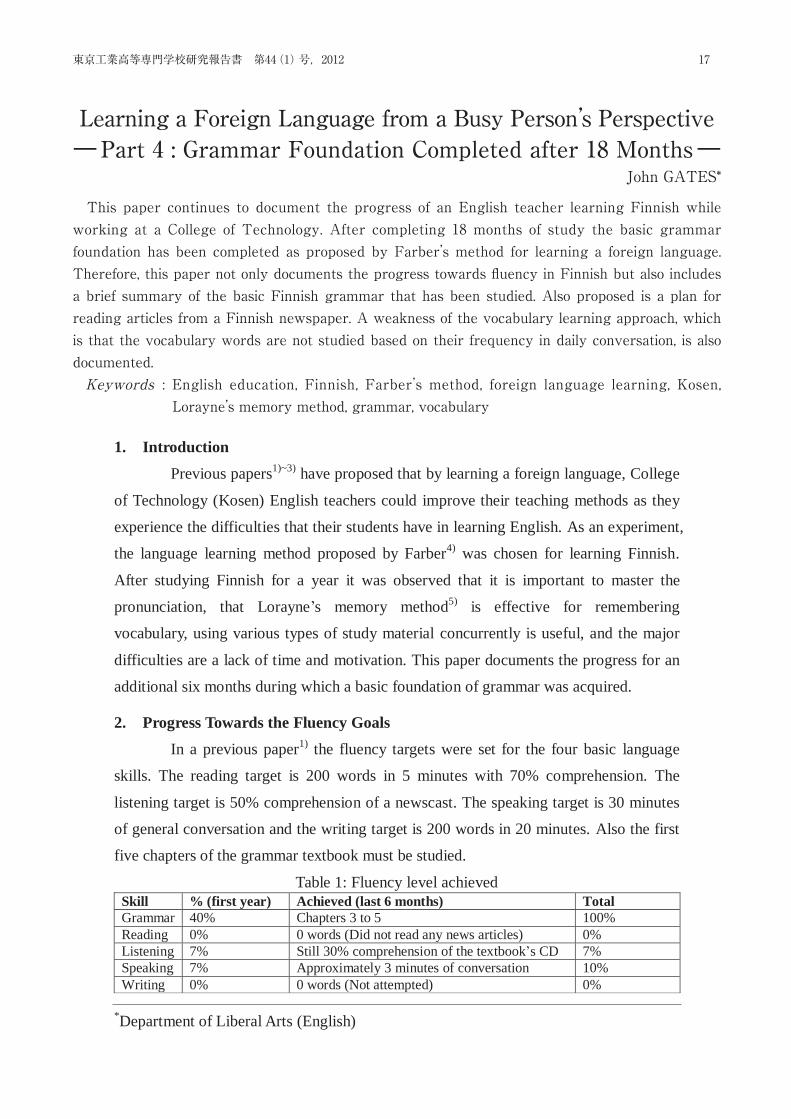
Table 1: Fluency level achieved Skill % (first year) Achieved (last 6 months) Total Grammar 40% Chapters 3 to 5 100% Reading 0% 0 words (Did not read any news articles) 0% Listening 7% Still 30% comprehension of the textbook’s CD 7% Speaking 7% Approximately 3 minutes of conversation 10% Writing 0% 0 words (Not attempted) 0%
*Department of Liberal Arts (English)
17東京工業高等専門学校研究報告書 第44(1)号,2012
This paper continues to document the progress of an English teacher learning Finnish while working at a College of Technology. After completing 18 months of study the basic grammar foundation has been completed as proposed by Farber’s method for learning a foreign language. Therefore, this paper not only documents the progress towards fl uency in Finnish but also includes a brief summary of the basic Finnish grammar that has been studied. Also proposed is a plan for reading articles from a Finnish newspaper. A weakness of the vocabulary learning approach, which is that the vocabulary words are not studied based on their frequency in daily conversation, is also documented.Keywords : English education, Finnish, Farber’s method, foreign language learning, Kosen, Lorayne’s memory method, grammar, vocabulary
Learning a Foreign Language from a Busy Person’s Perspective―Part 4 : Grammar Foundation Completed after 18 Months―
John GATES*
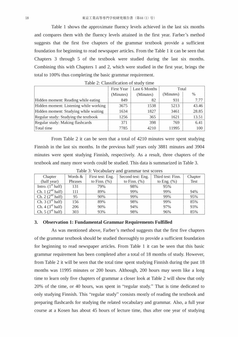
Table 1 shows the approximate fluency levels achieved in the last six months
and compares them with the fluency levels attained in the first year. Farber’s method
suggests that the first five chapters of the grammar textbook provide a sufficient
foundation for beginning to read newspaper articles. From the Table 1 it can be seen that
Chapters 3 through 5 of the textbook were studied during the last six months.
Combining this with Chapters 1 and 2, which were studied in the first year, brings the
total to 100% thus completing the basic grammar requirement.
Table 2: Classification of study time
First Year Last 6 Months Total (Minutes) (Minutes) (Minutes) %
Hidden moment: Reading while eating 849 82 931 7.77 Hidden moment: Listening while working 3675 1538 5213 43.46 Hidden moment: Studying while waiting 1634 1827 3461 28.85 Regular study: Studying the textbook 1256 365 1621 13.51 Regular study: Making flashcards 371 398 769 6.41 Total time 7785 4210 11995 100
From Table 2 it can be seen that a total of 4210 minutes were spent studying
Finnish in the last six months. In the previous half years only 3881 minutes and 3904
minutes were spent studying Finnish, respectively. As a result, three chapters of the
textbook and many more words could be studied. This data is summarized in Table 3.
Table 3: Vocabulary and grammar test scores Chapter
(half year) Words & Phrases
First test: Eng. to Finn. (%)
Second test: Eng. to Finn. (%)
Third test: Finn. to Eng. (%)
Chapter Test
Intro. (1st half) 131 79% 98% 95% Ch. 1 (2nd half) 111 89% 99% 99% 94% Ch. 2 (2nd half) 95 90% 99% 99% 95% Ch. 3 (3rd half) 156 89% 98% 99% 85% Ch. 4 (3rd half) 206 90% 94% 97% 93% Ch. 5 (3rd half) 303 93% 98% 96% 85%
3. Observation 1: Fundamental Grammar Requirements Fulfilled
As was mentioned above, Farber’s method suggests that the first five chapters
of the grammar textbook should be studied thoroughly to provide a sufficient foundation
for beginning to read newspaper articles. From Table 1 it can be seen that this basic
grammar requirement has been completed after a total of 18 months of study. However,
from Table 2 it will be seen that the total time spent studying Finnish during the past 18
months was 11995 minutes or 200 hours. Although, 200 hours may seem like a long
time to learn only five chapters of grammar a closer look at Table 2 will show that only
20% of the time, or 40 hours, was spent in “regular study.” That is time dedicated to
only studying Finnish. This “regular study” consists mostly of reading the textbook and
preparing flashcards for studying the related vocabulary and grammar. Also, a full year
course at a Kosen has about 45 hours of lecture time, thus after one year of studying
18 東京工業高等専門学校研究報告書(第44(1)号)
most Kosen students will have reached this level. In fact, as will be seen in Section 4,
most Kosen students will have studied the corresponding grammar material in junior
high school.
On the other hand, 80% of the time, or 160 hours, consists of “hidden
moments.” That is time spent studying Finnish while doing other things. From Table 2 it
can be seen that more than 40% of the total studying time consists of listening to the CD
from the textbook while doing other things. In addition, 30% of the total studying time
was spent memorizing flashcards while riding the train or waiting for appointments, etc.
This recovered time is greater than the amount of time spent in traditional study.
4. A Summary of the Grammar Studied in the First Five Chapters
According to Farber’s method, the next step after completing the fundamental
grammar requirement is to begin reading newspaper articles. Therefore, it is useful at
this point to document what grammatical structures have been studied. This section will
summarize the grammar structures of the first five chapters of the textbook and
demonstrate how Finnish is quite different from English and Japanese.
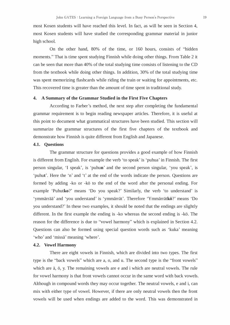
4.1. Questions
The grammar structure for questions provides a good example of how Finnish
is different from English. For example the verb ‘to speak’ is ‘puhua’ in Finnish. The first
person singular, ‘I speak’, is ‘puhun’ and the second person singular, ‘you speak’, is
‘puhut’. Here the ‘n’ and ‘t’ at the end of the words indicate the person. Questions are
formed by adding -ko or -kö to the end of the word after the personal ending. For
example ‘Puhutko?’ means ‘Do you speak?’ Similarly, the verb ‘to understand’ is
‘ymmärrää’ and ‘you understand’ is ‘ymmärrät’. Therefore ‘Ymmärrätkö?’ means ‘Do
you understand?’ In these two examples, it should be noted that the endings are slightly
different. In the first example the ending is -ko whereas the second ending is -kö. The
reason for the difference is due to “vowel harmony” which is explained in Section 4.2.
Questions can also be formed using special question words such as ‘kuka’ meaning
‘who’ and ‘missä’ meaning ‘where’.
4.2. Vowel Harmony
There are eight vowels in Finnish, which are divided into two types. The first
type is the “back vowels” which are a, o, and u. The second type is the “front vowels”
which are ä, ö, y. The remaining vowels are e and i which are neutral vowels. The rule
for vowel harmony is that front vowels cannot occur in the same word with back vowels.
Although in compound words they may occur together. The neutral vowels, e and i, can
mix with either type of vowel. However, if there are only neutral vowels then the front
vowels will be used when endings are added to the word. This was demonstrated in
19John GATES:Learning a Foreign Language from a Busy Person’s Perspective
Section 4.1 when the endings -ko and -kö were added to the end of the verbs to make
questions.
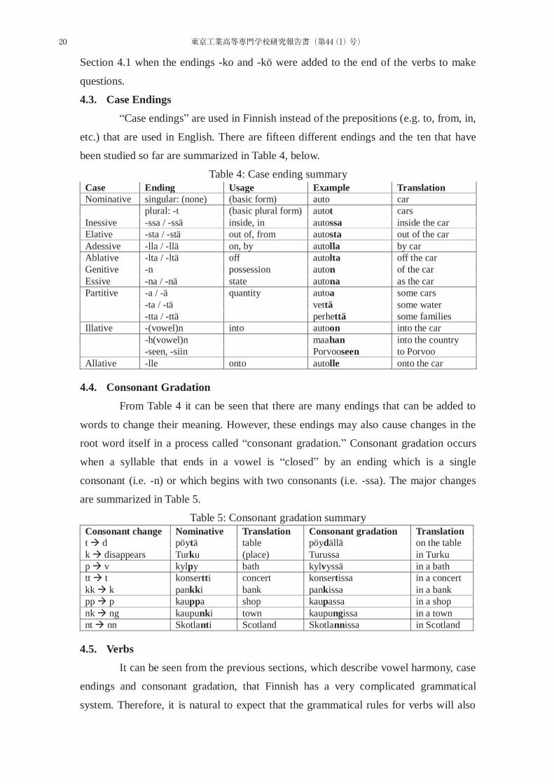
4.3. Case Endings
“Case endings” are used in Finnish instead of the prepositions (e.g. to, from, in,
etc.) that are used in English. There are fifteen different endings and the ten that have
been studied so far are summarized in Table 4, below.
Table 4: Case ending summary Case Ending Usage Example Translation Nominative singular: (none) (basic form) auto car plural: -t (basic plural form) autot cars Inessive -ssa / -ssä inside, in autossa inside the car Elative -sta / -stä out of, from autosta out of the car Adessive -lla / -llä on, by autolla by car Ablative -lta / -ltä off autolta off the car Genitive -n possession auton of the car Essive -na / -nä state autona as the car Partitive -a / -ä quantity autoa some cars -ta / -tä vettä some water -tta / -ttä perhettä some families Illative -(vowel)n into autoon into the car -h(vowel)n maahan into the country -seen, -siin Porvooseen to Porvoo Allative -lle onto autolle onto the car
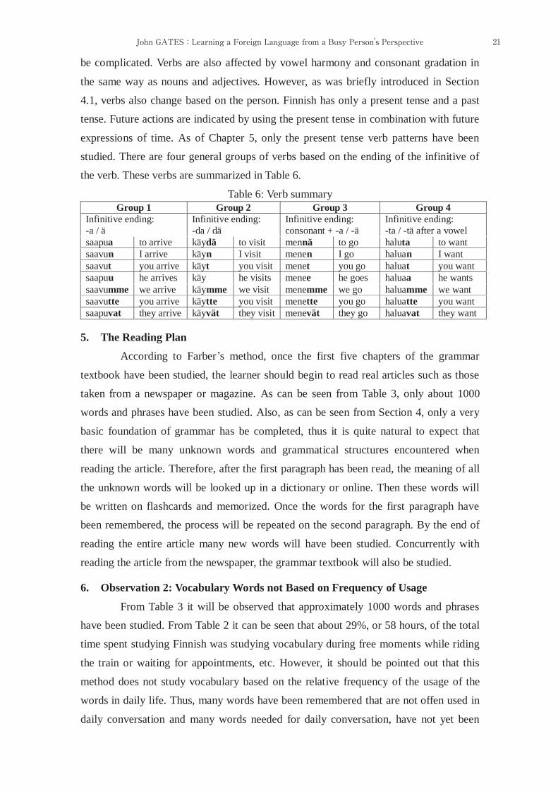
4.4. Consonant Gradation
From Table 4 it can be seen that there are many endings that can be added to
words to change their meaning. However, these endings may also cause changes in the
root word itself in a process called “consonant gradation.” Consonant gradation occurs
when a syllable that ends in a vowel is “closed” by an ending which is a single
consonant (i.e. -n) or which begins with two consonants (i.e. -ssa). The major changes
are summarized in Table 5.
Table 5: Consonant gradation summary Consonant change Nominative Translation Consonant gradation Translation t d pöytä table pöydällä on the table k disappears Turku (place) Turussa in Turku p v kylpy bath kylvyssä in a bath tt t konsertti concert konsertissa in a concert kk k pankki bank pankissa in a bank pp p kauppa shop kaupassa in a shop nk ng kaupunki town kaupungissa in a town nt nn Skotlanti Scotland Skotlannissa in Scotland
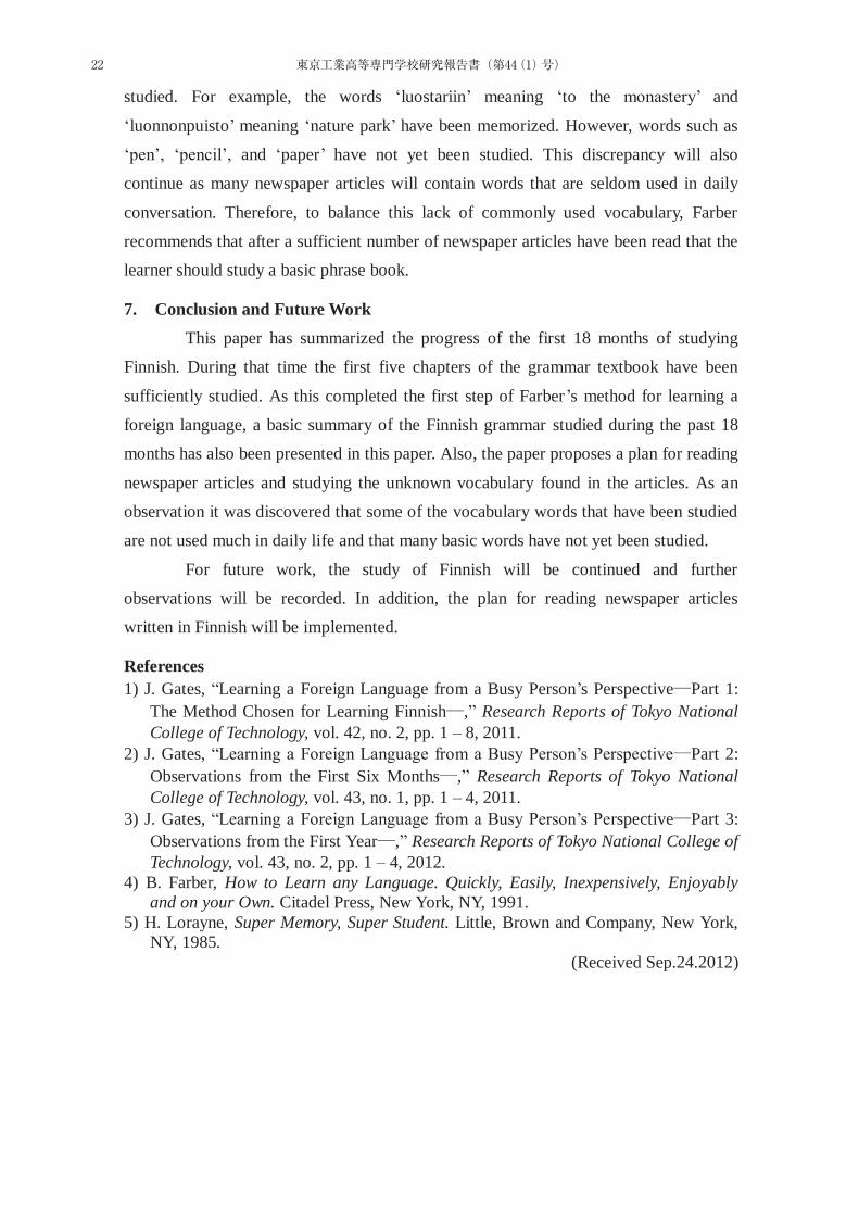
4.5. Verbs
It can be seen from the previous sections, which describe vowel harmony, case
endings and consonant gradation, that Finnish has a very complicated grammatical
system. Therefore, it is natural to expect that the grammatical rules for verbs will also
20 東京工業高等専門学校研究報告書(第44(1)号)
be complicated. Verbs are also affected by vowel harmony and consonant gradation in
the same way as nouns and adjectives. However, as was briefly introduced in Section
4.1, verbs also change based on the person. Finnish has only a present tense and a past
tense. Future actions are indicated by using the present tense in combination with future
expressions of time. As of Chapter 5, only the present tense verb patterns have been
studied. There are four general groups of verbs based on the ending of the infinitive of
the verb. These verbs are summarized in Table 6.
Table 6: Verb summary Group 1 Group 2 Group 3 Group 4
Infinitive ending: -a / ä
Infinitive ending: -da / dä
Infinitive ending: consonant + -a / -ä
Infinitive ending: -ta / -tä after a vowel
saapua to arrive käydä to visit mennä to go haluta to want saavun I arrive käyn I visit menen I go haluan I want saavut you arrive käyt you visit menet you go haluat you want saapuu he arrives käy he visits menee he goes haluaa he wants saavumme we arrive käymme we visit menemme we go haluamme we want saavutte you arrive käytte you visit menette you go haluatte you want saapuvat they arrive käyvät they visit menevät they go haluavat they want
5. The Reading Plan
According to Farber’s method, once the first five chapters of the grammar
textbook have been studied, the learner should begin to read real articles such as those
taken from a newspaper or magazine. As can be seen from Table 3, only about 1000
words and phrases have been studied. Also, as can be seen from Section 4, only a very
basic foundation of grammar has be completed, thus it is quite natural to expect that
there will be many unknown words and grammatical structures encountered when
reading the article. Therefore, after the first paragraph has been read, the meaning of all
the unknown words will be looked up in a dictionary or online. Then these words will
be written on flashcards and memorized. Once the words for the first paragraph have
been remembered, the process will be repeated on the second paragraph. By the end of
reading the entire article many new words will have been studied. Concurrently with
reading the article from the newspaper, the grammar textbook will also be studied.
6. Observation 2: Vocabulary Words not Based on Frequency of Usage
From Table 3 it will be observed that approximately 1000 words and phrases
have been studied. From Table 2 it can be seen that about 29%, or 58 hours, of the total
time spent studying Finnish was studying vocabulary during free moments while riding
the train or waiting for appointments, etc. However, it should be pointed out that this
method does not study vocabulary based on the relative frequency of the usage of the
words in daily life. Thus, many words have been remembered that are not offen used in
daily conversation and many words needed for daily conversation, have not yet been
21John GATES:Learning a Foreign Language from a Busy Person’s Perspective
studied. For example, the words ‘luostariin’ meaning ‘to the monastery’ and
‘luonnonpuisto’ meaning ‘nature park’ have been memorized. However, words such as
‘pen’, ‘pencil’, and ‘paper’ have not yet been studied. This discrepancy will also
continue as many newspaper articles will contain words that are seldom used in daily
conversation. Therefore, to balance this lack of commonly used vocabulary, Farber
recommends that after a sufficient number of newspaper articles have been read that the
learner should study a basic phrase book.
7. Conclusion and Future Work
This paper has summarized the progress of the first 18 months of studying
Finnish. During that time the first five chapters of the grammar textbook have been
sufficiently studied. As this completed the first step of Farber’s method for learning a
foreign language, a basic summary of the Finnish grammar studied during the past 18
months has also been presented in this paper. Also, the paper proposes a plan for reading
newspaper articles and studying the unknown vocabulary found in the articles. As an
observation it was discovered that some of the vocabulary words that have been studied
are not used much in daily life and that many basic words have not yet been studied.
For future work, the study of Finnish will be continued and further
observations will be recorded. In addition, the plan for reading newspaper articles
written in Finnish will be implemented.
References 1) J. Gates, “Learning a Foreign Language from a Busy Person’s Perspective Part 1:
The Method Chosen for Learning Finnish ,” Research Reports of Tokyo National College of Technology, vol. 42, no. 2, pp. 1 – 8, 2011.
2) J. Gates, “Learning a Foreign Language from a Busy Person’s Perspective Part 2: Observations from the First Six Months ,” Research Reports of Tokyo National College of Technology, vol. 43, no. 1, pp. 1 – 4, 2011.
3) J. Gates, “Learning a Foreign Language from a Busy Person’s Perspective Part 3: Observations from the First Year ,” Research Reports of Tokyo National College of Technology, vol. 43, no. 2, pp. 1 – 4, 2012.
4) B. Farber, How to Learn any Language. Quickly, Easily, Inexpensively, Enjoyably and on your Own. Citadel Press, New York, NY, 1991.
5) H. Lorayne, Super Memory, Super Student. Little, Brown and Company, New York, NY, 1985.
(Received Sep.24.2012)
22 東京工業高等専門学校研究報告書(第44(1)号)

An analysis of class communities by using Questionnaire-Utilities
Kazutoshi Kuroda
We have conducted QU that targets TNCT freshman in April and December. Analysis of the QU shows
that TNCT students ware very high motivation for learning in April. It was reduced in about 8 months, however. Correlation was found between the learning achievement and motivation for learning. A comparison of the December and April, the score of "relationships with friends" and "feeling of infringement" became high in December. On the other hand, "consideration for others" score ware decreased. There ware differences in "relationship with teachers" and "Adaptation to the class community" between classes.
Keywords QU, class communities, satisfaction with school life, willingness school life, social skill
Questionnaire-Utilities
Hyper- 1)
2009 2010
PDCA
Hyper-
2011 N = 214
23東京工業高等専門学校研究報告書 第44(1)号,2012
We have conducted QU that targets TNCT freshman in April and December. Analysis of the QU shows that TNCT students ware very high motivation for learning in April. It was reduced in about 8 months, however. Correlation was found between the learning achievement and motivation for learning. A comparison of the December and April, the score of“relationships with friends”and“feeling of infringement”became high in December. On the other hand,“consideration for others”score ware decreased. There ware diff erences in“relationship with teachers”and“Adaptation to the class community”between classes.Keywords : QU, class communities, satisfaction with school life, willingness school life, social skill
Q―Uを用いた学級集団の分析黒田一寿*
An analysis of class communities by using Questionnaire-UtilitiesKazutoshi KURODA
Hyper-
¥500
15 20 73 2011
raw
CD-ROMSPSS ver.19
Hyper-
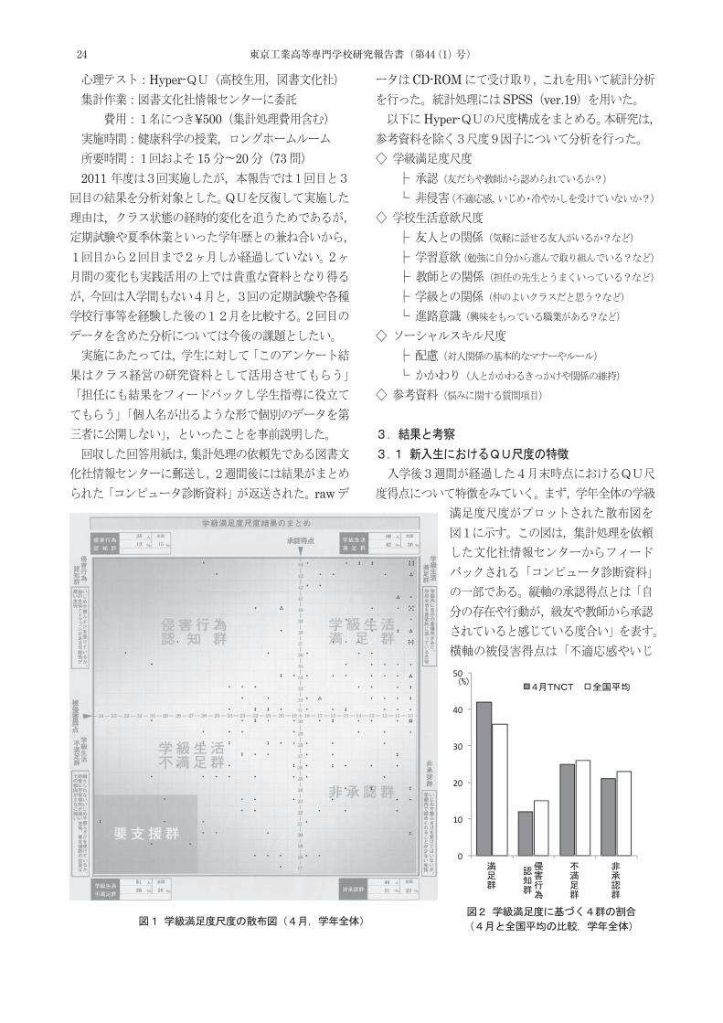
24 東京工業高等専門学校研究報告書(第44(1)号)
42
36
2526
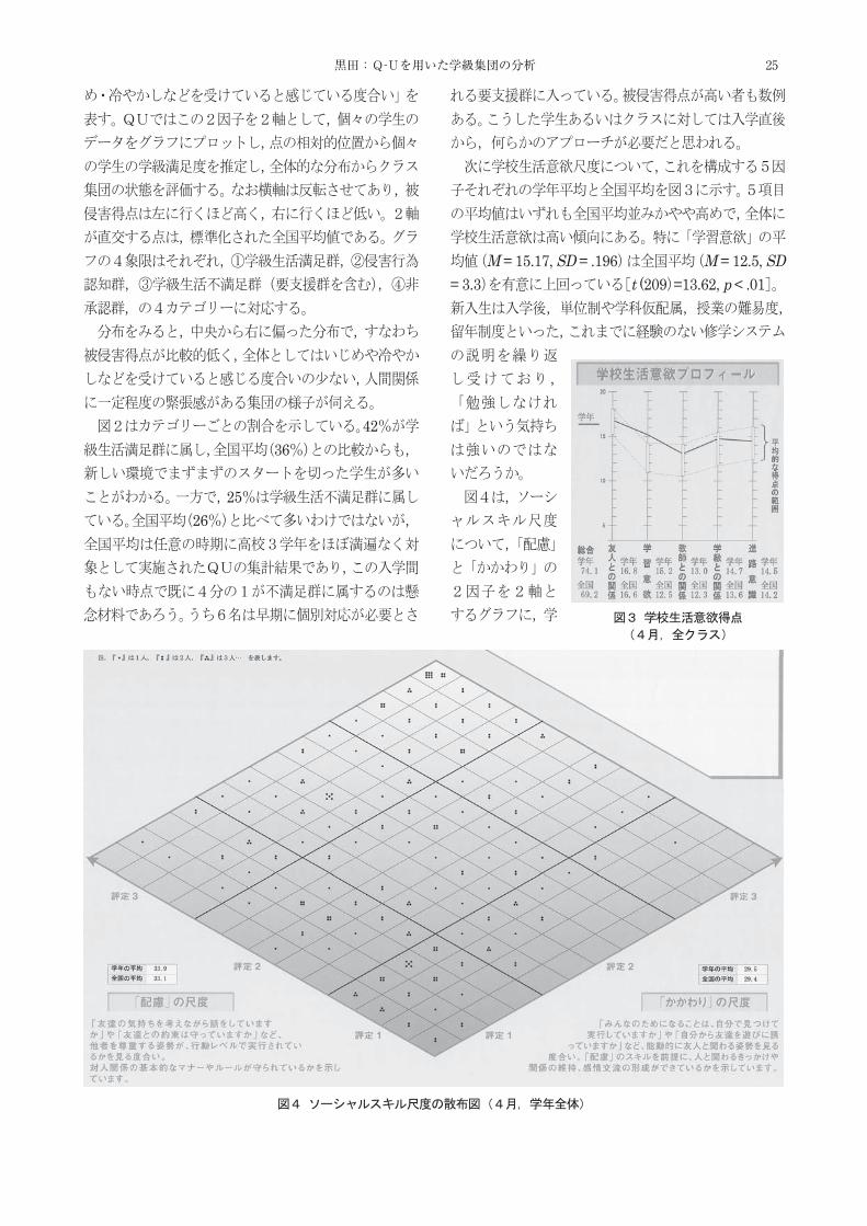
M = 15.17, SD = .196 M = 12.5, SD = 3.3 t (209 =13.62, p < .01
25黒田:Q-Uを用いた学級集団の分析

2)
2)
M = 33.86, SD = .272 M = 33.1, SD = 4.4 t (209) = 2.74, p < .01
M = 29.48, SD = .412M = 29.4, SD = 5.7
5
26 東京工業高等専門学校研究報告書(第44(1)号)
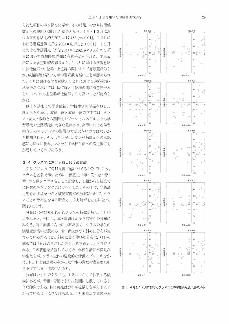
12 19
11
t (197) = 2.33, p < .05 ,
t (201) = 7.61, p < .001
M = 12.5, SD = 3.3M = 15.21 12 M = 13.52
t (200) = 7.79, p < .001
t (202) = 4.31, p < .01
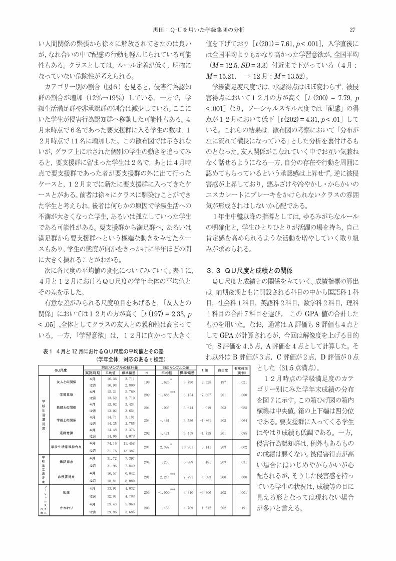
GPAA S
GPAS .5 A 4
B C D31.5
27黒田:Q-Uを用いた学級集団の分析
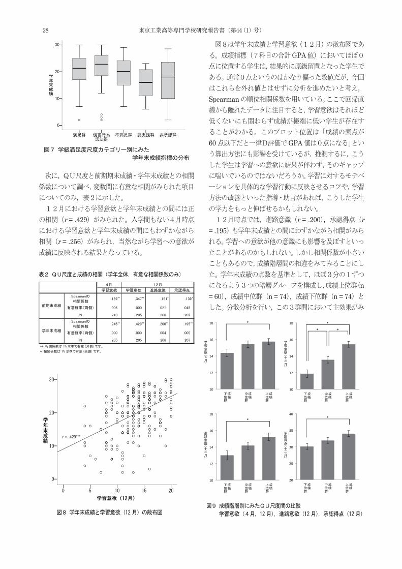
r = .429
r = .256
GPA
Spearman
60 GPA
r = .200 r
= .195
n = 60 n = 74 n = 74
28 東京工業高等専門学校研究報告書(第44(1)号)
F (2,202) = 17.483, p < 0.01F (2,203) = 5.171, p < 0.01
F (2,204) = 4.262, p < 0.05Tukey
10
15
20
25
30
35
40
45
15
20
25
30
35
40
45
15
20
25
30
35
40
45
15
20
25
30
35
40
45
15
20
25
30
35
40
45
15
20
25
30
35
40
45
15
20
25
30
35
40
45
15
20
25
30
35
40
45
15
20
25
30
35
40
45
15
20
25
30
35
40
45
29黒田:Q-Uを用いた学級集団の分析
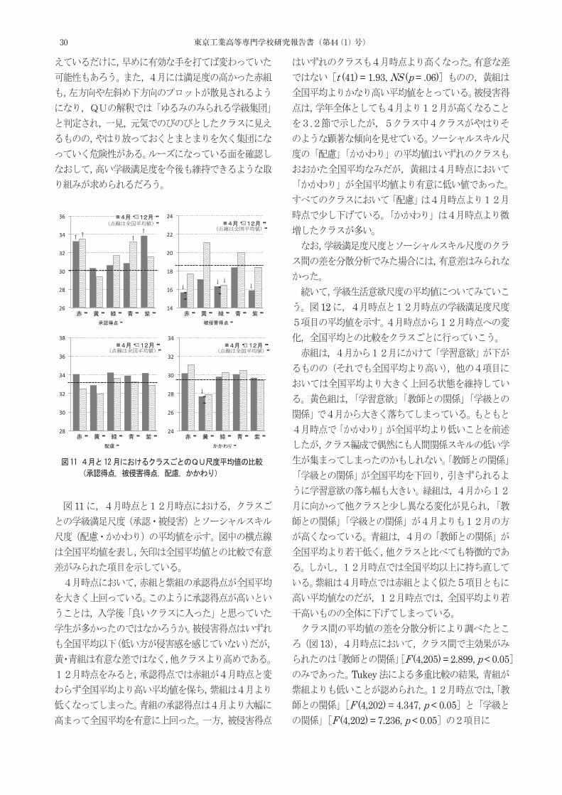
11
t (41) = 1.93, NS (p = .06)
.
12
13F (4,205) = 2.899, p < 0.05
Tukey
F (4,202) = 4.347, p < 0.05F (4,202) = 7.236, p < 0.05
26�
28�
30�
32�
34�
36�
14�
16�
18�
20�
22�
24�
28�
30�
32�
34�
36�
38�
24�
26�
28�
30�
32�
34�
30 東京工業高等専門学校研究報告書(第44(1)号)

Tukey
14
10��
12��
14��
16��
18��
20��
10��
12��
14��
16��
18��
20��
10��
12��
14��
16��
18��
20��
10��
12��
14��
16��
18��
20��
10��
12��
14��
16��
18��
20��
8
10
12
14
16
18
20
*
8
10
12
14
16
18
20
12
**
8
10
12
14
16
18
20
12
** *
*
31黒田:Q-Uを用いた学級集団の分析
32 東京工業高等専門学校研究報告書(第44(1)号)
Sumio SAITO* , Masaaki TAKAHASHI**, Yoshimi NAGATA***, Takuya IWAMURA****
Keita DEJIMA***** and Gaku HIJIKATA****** Recent ly, as global-scale problems, such as global warming and energy deplet ion,
have attracted attent ion, the importance of future environmental preservat ion has been emphasized worldwide, and various measures have been proposed and implemented. Water hammer pumps can effectively use the water hammer phenomenon in long -distance pipeline networks that include pumps and allow fluid transpor t without drive sources, such as electric motors. The results of experiments that examined the effect of the geometric form of water hammer pumps by considering their major dimensions have been reported. However, these conventional studies have not fully e valuated the pump performance in terms of pump head and flow rate, common measures indicat ing the performance of pumps. The previous paper experimentally examined how the hydrodynamic characterist ics were affected by the inner diameter rat io of the drive a nd lift ing pipes, the form of the air chamber, and the angle of the drive pipe . This paper proposes the effect of air volume in air chamber that affects the hydrodynamic characterist ics and operation condit ions of the water hammer pump and also clarifies the flow behaviors in the valve chamber by using the flow visualization method during water hammer pump operat ion.
(Keywords: Water Hammer Pump, Fluid Transients, Pump Performance, Pressure Fluctuation,
Velocity Fluctuation, Flow Visualization)
1. Introduction
In the field of energy- and life-related technology, a variety of fluid machines play an important role in
the infrastructure of society, and more energy-saving and resource-saving machinery will be needed.
Water hammer pumps, which effect ively use the water hammer phenomenon that imposes a
problem in fluid pipeline networks including pumps, are a promising means for effect ively
transporting fluid even in regions lacking developed infrastructures due to its ability to
transport water without drive sources, such as electric motors.
Convent ional studies on water hammer pumps include those that propose configurations
mainly for educational purposes [1], [2], [3]; the results of experiments that examined effects
of major specificat ions for the geometric form o f water hammer pumps [4], [5]; and a paper
that analyzes the water hammer phenomenon numerically by using the characteristic curve
method for comparison with experimental results [6 ]. These studies, however, have not fully
evaluated the relat ionship between pump head and flow rate, common measures indicating
pump performance.
* Department of Mechanical Engineering ** Yokohama Nat ional University *** Yamaha Motor Engineering Co., Ltd. **** Mechanical and Computer Systems Engineering, Advanced Engineering Course ***** Nagaoka University of Technology ****** Tokyo Waterworks Service Co., Ltd.
Pump Performance and Flow Behavior in Valve Chamber according to Changes of Air Volume in Air Chamber
in Water Hammer Pump System
33東京工業高等専門学校研究報告書 第44(1)号,2012
Recently, as global-scale problems, such as global warming and energy depletion, have attracted attention, the importance of future environmental preservation has been emphasized worldwide, and various measures have been proposed and implemented. Water hammer pumps can eff ectively use the water hammer phenomenon in long-distance pipeline networks that include pumps and allow fluid transport without drive sources, such as electric motors. The results of experiments that examined the eff ect of the geometric form of water hammer pumps by considering their major dimensions have been reported. However, these conventional studies have not fully evaluated the pump performance in terms of pump head and flow rate, common measures indicating the performance of pumps. The previous paper experimentally examined how the hydrodynamic characteristics were affected by the inner diameter ratio of the drive and lifting pipes, the form of the air chamber, and the angle of the drive pipe. This paper proposes the eff ect of air volume in air chamber that affects the hydrodynamic characteristics and operation conditions of the water hammer pump and also clarifi es the fl ow behaviors in the valve chamber by using the fl ow visualization method during water hammer pump operation.Keywords : Water Hammer Pump, Fluid Transients, Pump Performance, Pressure Fluctuation, Velocity Fluctuation, Flow Visualization
Pump Performance and Flow Behavior in Valve Chamber according toChanges of Air Volume in Air Chamber in Water Hammer Pump System
Sumio SAITO*, Masaaki TAKAHASHI**, Yoshimi NAGATA***, Takuya IWAMURA****,Keita DEJIMA***** and Gaku HIJIKATA******

This study examines the relationship between the temporal pressure fluctuat ions in the valve and
air chambers at different air volumes in the air chamber and the performance of the water
hammer pump to elucidate the behavior around the valve and air chambers that affects the
operat ing condit ions of the water hammer pump, and, at the same t ime, clarifies flow behaviors
in the valve chamber during the pump operation.
2. Experimental Apparatus and Method
2.1 Experimental Apparatus
Figure 1 shows an overall schematic diagram of the water hammer pump system used for the
experiment. Figure 2 shows a detailed schematic diagram of the water hammer pump, including
the valve chamber and its associated parts. The pump is composed of main parts from the water
tank (1) to the spring (8).
The drive pipe (2), which supplies water from the water tank (1) to the valve chamber (3) , is
made of acrylic resin material to allow the visualizat ion of internal flow. The valve chamber
(3) and the air chamber (6) are also made of acrylic resin material and configured so that ink
can be injected for the visualizat ion of flow in the valve chamber. The valve chamber (3) has a
seat on its wall, on which an electro-magnet ic flow velocity meter can be attached.
Fig. 1 Water hammer pump system
Fig. 2 Main parts of water hammer pump
34 東京工業高等専門学校研究報告書(第44(1)号)
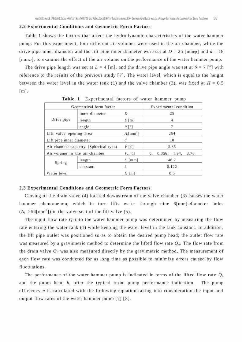
2.2 Experimental Conditions and Geometric Form Factors
Table 1 shows the factors that affect the hydrodynamic characterist ics of the water hammer
pump. For this experiment, four different air volumes were used in the air chamber, while the
drive pipe inner diameter and the lift pipe inner diameter were set at D = 25 [mmφ] and d = 18
[mmφ], to examine the effect of the air volume on the perfo rmance of the water hammer pump.
The drive pipe length was set at L = 4 [m], and the drive pipe angle was set at θ = 7 [°] with
reference to the results of the previous study [7]. The water level, which is equal to the height
between the water level in the water tank (1) and the valve chamber (3), was fixed at H = 0.5
[m].
Table. 1 Experimental factors of water hammer pump
Geometrical form factor Experimental condit ion
Drive pipe inner diameter D 25
length L [m] 4
angle θ [°] 7
Lift valve opening area Al[mm2] 254
Lift pipe inner diameter d 18
Air chamber capacity (Spherical type) V [ℓ] 3.85
Air volume in the air chamber Va [ℓ] 0, 0.356, 1.94, 3.76
Spring length ℓs [mm] 46.7
constant k 0.122
Water level H [m] 0.5
2.3 Experimental Conditions and Geometric Form Factors
Closing of the drain valve (4) located downstream of the valve chamber (3) causes the water
hammer phenomenon, which in turn lifts water through nine 6[mm] -diameter holes
(Al=254[mm2]) in the valve seat of the lift valve (5).
The input flow rate Qi into the water hammer pump was determined by measuring the flow
rate entering the water tank (1) while keeping the water level in the tank constant. In addit ion,
the lift pipe out let was positioned so as to obtain the desired pump head; the outlet flow rate
was measured by a gravimetric method to determine the lifted flow rate Qu. The flow rate from
the drain valve Qd was also measured directly by the gravimetric method. The measurement of
each flow rate was conducted for as long t ime as possible to minimize errors caused by flow
fluctuations.
The performance of the water hammer pump is indicated in terms of the lifted flow rate Qu
and the pump head h, after the typical turbo pump performance indicat ion. The pump
efficiency η is calculated with the following equation taking into considerat ion the input and
output flow rates of the water hammer pump [7] [8].
35Sumio SAITO, Masaaki TAKAHASHI, Yoshimi NAGATA, Takuya IWAMURA, Keita DEJIMA, Gaku HIJIKATA:Pump Performance and Flow Behavior in Valve Chamber according to Changes of Air Volume in Air Chamber in Water Hammer Pump System
Hh
QQQ
HQhQ
ηud
u
i
u×
+=
××
=Hh
ηv ×= (1)
where ηv (= Qu / (Qd+Qu ) ) indicates volumetric efficiency of the water hammer pump.
To invest igate the hydrodynamic behavior in the water hammer pump, temporal changes in
pressure Pv in the valve chamber (3) and Pa in the air chamber (6) shown in Figure 2 are
measured with a pair of strain gauge pressure transducer (PGM-1KG, manufactured by Kyowa
Electronic Instruments Co., Ltd.), an amplifier and an A/D converter.
Furthermore, in order to examine the flow behavior in the valve chamber , a sensor of an
electro-magnet ic velocity meter (VM-801H, manufactured by KENEK Corporat ion) capable of
measuring simultaneously flow velocity vx in the flow direction from the drive pipe and flow
velocity vy in the water lift ing direct ion is installed vert ically at the center of the valve
chamber and horizontally co-axial to the center of the lift valve.
For the behavior of flow in the valve chamber, the internal flow was visualized and
observed by inject ing ink upstream of the valve chamber.
3. Experimental Results and Discussion
3.1 Changes in Water Hammer Pump Performance at Diffe rent Air Volumes in the Air
Chamber
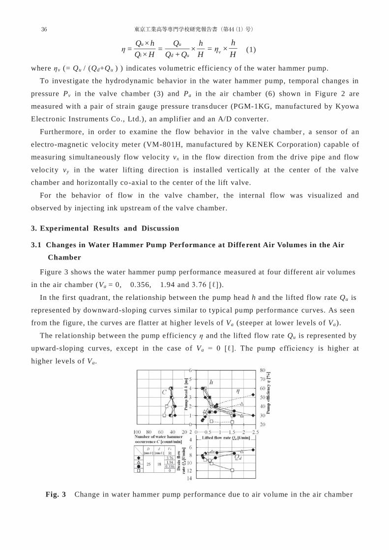
Figure 3 shows the water hammer pump performance measured at four different air volumes
in the air chamber (Va = 0, 0.356, 1.94 and 3.76 [ℓ]).
In the first quadrant, the relationship between the pump head h and the lifted flow rate Qu is
represented by downward-sloping curves similar to typical pump performance curves. As seen
from the figure, the curves are flatter at higher levels of Va (steeper at lower levels of Va).
The relat ionship between the pump efficiency η and the lifted flow rate Qu is represented by
upward-sloping curves, except in the case of Va = 0 [ℓ]. The pump efficiency is higher at
higher levels of Va.
Fig. 3 Change in water hammer pump performance due to air volume in the air chamber
36 東京工業高等専門学校研究報告書(第44(1)号)
The fourth quadrant represents the relat ionship between the drain flow rate Qd and the lifted
flow rate Qu. Only when Va = 0 [ℓ], the drain flow rate increases as the lifted flow rate
increases. Except in the case of Va = 0 [ℓ], the drain flow rate is lower at higher levels of Va
and remains almost constant regardless of the lifted flow rates Qu.
In the second quadrant, the number of water hammer occurrences C is around 40 [count/min]
regardless of the pump head h.
3.2 Temporal Pressure Fluctuations in Valve and Air Chambers of Water Hammer Pump
3.2.1 Operating Principle of Water Hammer Pump
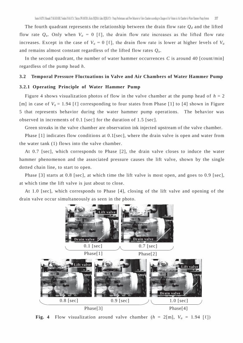
Figure 4 shows visualizat ion photos of flow in the valve chamber at the pump head of h = 2
[m] in case of Va = 1.94 [ℓ] corresponding to four states from Phase [1] to [4] shown in Figure
5 that represents behavior during the water hammer pump operat ions. The behavior was
observed in increments of 0.1 [sec] for the durat ion of 1.5 [sec].
Green streaks in the valve chamber are observation ink injected upstream of the valve chamber.
Phase [1] indicates flow condit ions at 0.1[sec], where the drain valve is open and water from
the water tank (1) flows into the valve chamber.
At 0.7 [sec], which corresponds to Phase [2], the drain valve closes to induce the water
hammer phenomenon and the associated pressure causes the lift valve, shown by the single
dotted chain line, to start to open.
Phase [3] starts at 0.8 [sec], at which t ime the lift valve is most open, and goes to 0.9 [sec],
at which t ime the lift valve is just about to close.
At 1.0 [sec], which corresponds to Phase [4], closing of the lift valve and opening of the
drain valve occur simultaneously as seen in the photo.
Phase[1] Phase[2]
0.1 [sec] 0.7 [sec]
0.8 [sec] 0.9 [sec] 1.0 [sec] Phase[3] Phase[4]
Lift valve
Drain valve Drain valve
Lift valve Lift valve
Drain valve
Fig. 4 Flow visualizat ion around valve chamber (h = 2[m], Va = 1.94 [ℓ])
37Sumio SAITO, Masaaki TAKAHASHI, Yoshimi NAGATA, Takuya IWAMURA, Keita DEJIMA, Gaku HIJIKATA:Pump Performance and Flow Behavior in Valve Chamber according to Changes of Air Volume in Air Chamber in Water Hammer Pump System
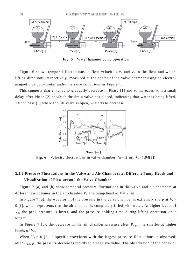
Fig. 5 Water hammer pump operat ion
Figure 6 shows temporal fluctuations in flow velocit ies vx and vy in the flow and water-
lift ing direct ions, respectively, measured at the center of the valve chamber using an electro -
magnet ic velocity meter under the same condit ions as Figure 4.
This suggests that vx tends to gradually decrease in Phase [1] and vy increases with a small
delay after Phase [2] at which the drain valve has closed, indicat ing that water is being lifted.
After Phase [3] where the lift valve is open, vy starts to decrease.
3.2.2 Pressure Fluctuations in the Valve and Air Chambers at Different Pump Heads and
Visualization of Flow around the Valve Chamber
Figure 7 (a) and (b) show temporal pressure fluctuat ions in the valve and air chambers at
different air volumes in the air chamber Va at a pump head of h = 2 [m].
In Figure 7 (a), the waveform of the pressure in the valve chamber is extremely sharp at Va =
0 [ℓ], which represents that the air chamber is completely filled with water. At higher levels of
Va, the peak pressure is lower, and the pressure holding time during lift ing operat ion Δt is
longer.
In Figure 7 (b), the decrease in the air chamber pressure after Pa.peak is smaller at higher
levels of Va.
When Va = 0 [ℓ], a specific waveform with the largest pressure fluctuations is observed;
after Pa.peak, the pressure decreases rapidly to a negat ive value. The observat ion of the behavior
Fig. 6 Velocity fluctuat ions in valve chamber (h 2[m], Va=1.94[ℓ])
Time t [sec]
38 東京工業高等専門学校研究報告書(第44(1)号)
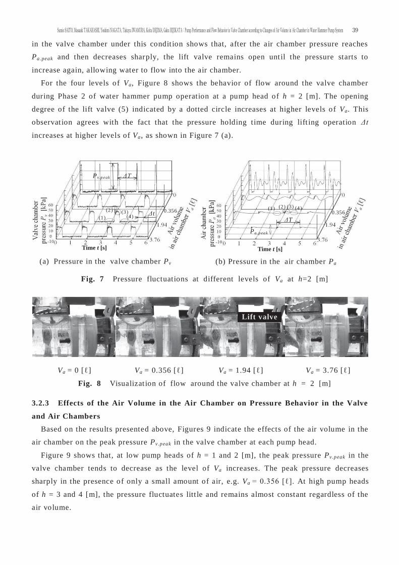
in the valve chamber under this condit ion shows that, after the air chamber pressure reaches
Pa.peak and then decreases sharply, the lift valve remains open unt il the pressure starts to
increase again, allowing water to flow into the air chamber.
For the four levels of Va, Figure 8 shows the behavior of flow around the valve chamber
during Phase 2 of water hammer pump operation at a pump head of h = 2 [m]. The opening
degree of the lift valve (5) indicated by a dotted circle increases at higher levels of Va. This
observat ion agrees with the fact that the pressure holding time during lift ing operation Δt
increases at higher levels of Va, as shown in Figure 7 (a).
Fig. 7 Pressure fluctuations at different levels of Va at h=2 [m]
Va = 0 [ℓ] Va = 0.356 [ℓ] Va = 1.94 [ℓ] Va = 3.76 [ℓ]
Fig. 8 Visualizat ion of flow around the valve chamber at h = 2 [m]
Va = 0 [ℓ] Va = 0.356 [ℓ] Va = 1.94 [ℓ] Va = 3.76 [ℓ]
Fig. 8 Visualizat ion of flow around the valve chamber at h = 2 [m]
3.2.3 Effects of the Air Volume in the Air Chamber on Pressure Behavior in the Valve
and Air Chambers
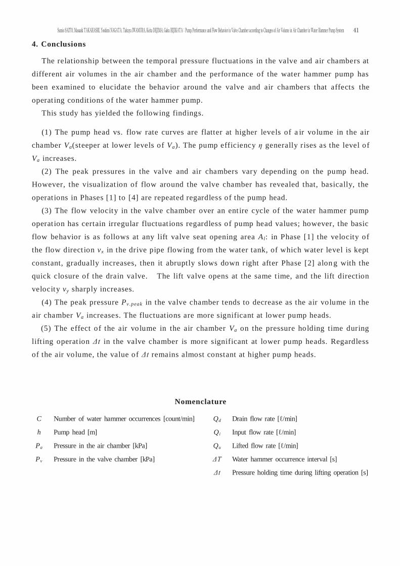
Based on the results presented above, Figures 9 indicate the effects of the air volume in the
air chamber on the peak pressure Pv.peak in the valve chamber at each pump head.
Figure 9 shows that, at low pump heads of h = 1 and 2 [m], the peak pressure Pv.peak in the
valve chamber tends to decrease as the level of Va increases. The peak pressure decreases
sharply in the presence of only a small amount of air, e.g. Va = 0.356 [ℓ]. At high pump heads
of h = 3 and 4 [m], the pressure fluctuates litt le and remains almost constant regardless of the
air volume.
(a) Pressure in the valve chamber Pv
Δt
Pv.p eak ΔT
(1) (2) (3) 0.356
(4) ΔT
Pa.p ea k
(2) (1) (3) 0.356
(b) Pressure in the air chamber Pa time t [s]
(4)
Lift valve
Time t [s] Time t [s]
39Sumio SAITO, Masaaki TAKAHASHI, Yoshimi NAGATA, Takuya IWAMURA, Keita DEJIMA, Gaku HIJIKATA:Pump Performance and Flow Behavior in Valve Chamber according to Changes of Air Volume in Air Chamber in Water Hammer Pump System
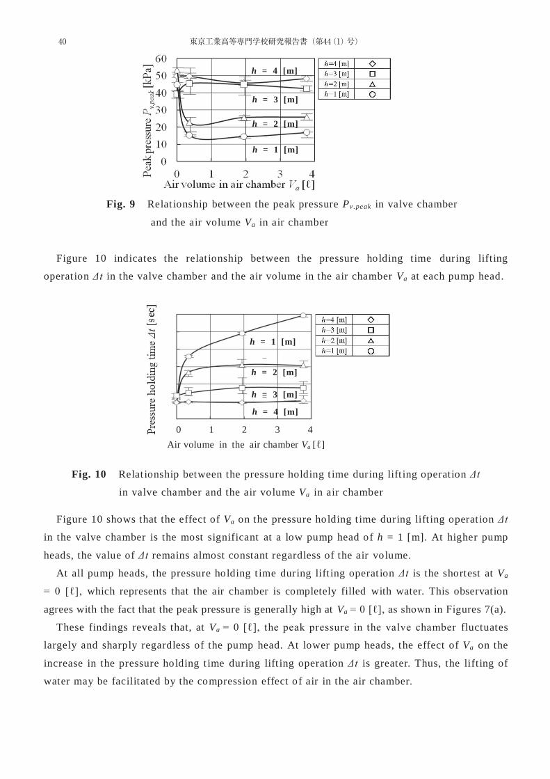
Fig. 9 Relat ionship between the peak pressure Pv.peak in valve chamber
and the air volume Va in air chamber
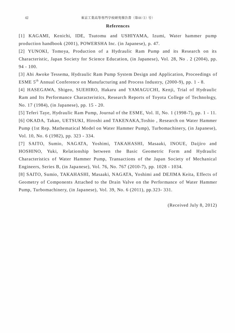
Figure 10 indicates the relat ionship between the pressure holding time during lifting
operat ion Δt in the valve chamber and the air volume in the air chamber Va at each pump head.
Fig. 10 Relat ionship between the pressure holding t ime during lift ing operation Δt
in valve chamber and the air volume Va in air chamber
Figure 10 shows that the effect of Va on the pressure holding t ime during lift ing operat ion Δt
in the valve chamber is the most significant at a low pump head of h = 1 [m]. At higher pump
heads, the value of Δt remains almost constant regardless of the air volume.
At all pump heads, the pressure holding t ime during lift ing operat ion Δt is the shortest at Va
= 0 [ℓ], which represents that the air chamber is completely filled with water. This observation
agrees with the fact that the peak pressure is generally high at Va = 0 [ℓ], as shown in Figures 7(a).
These findings reveals that, at Va = 0 [ℓ], the peak pressure in the valve chamber fluctuates
largely and sharply regardless of the pump head. At lower pump heads, the effect of Va on the
increase in the pressure holding t ime during lift ing operat ion Δt is greater. Thus, the lifting of
water may be facilitated by the compression effect of air in the air chamber.
h = 4 [m]
h = 1 [m]
h = 2 [m]
h = 3 [m]
h = 1 [m]
h = 4 [m]
h = 2 [m]
h = 3 [m]
0 1 2 3 4
hh = 11 [m]
h = 4 [m[[[[ ]]]]]]]]]]
h = 2 [m]
h = 3 [m]
Air volume in the air chamber Va [ℓ]
h = 1 [m]
h = 2 [m]
h = 3 [m]
h = 4 [m]
40 東京工業高等専門学校研究報告書(第44(1)号)
4. Conclusions
The relationship between the temporal pressure fluctuat ions in the valve and air chambers at
different air volumes in the air chamber and the performance of the water hammer pump has
been examined to elucidate the behavior around the valve and air chambers that affects the
operat ing condit ions of the water hammer pump.
This study has yielded the following findings.
(1) The pump head vs. flow rate curves are flatter at higher levels of a ir volume in the air
chamber Va(steeper at lower levels of Va). The pump efficiency η generally rises as the level of
Va increases.
(2) The peak pressures in the valve and air chambers vary depending on the pump head.
However, the visualizat ion of flow around the valve chamber has revealed that, basically, the
operat ions in Phases [1] to [4] are repeated regardless of the pump head.
(3) The flow velocity in the valve chamber over an ent ire cycle of the water hammer pump
operat ion has certain irregular fluctuat ions regardless of pump head values; however, the basic
flow behavior is as follows at any lift valve seat opening area Al: in Phase [1] the velocity of
the flow direct ion vx in the drive pipe flowing from the water tank, of which water level is kept
constant, gradually increases, then it abruptly slows down right after Phase [2] alon g with the
quick closure of the drain valve. The lift valve opens at the same t ime, and the lift direction
velocity vy sharply increases.
(4) The peak pressure Pv.peak in the valve chamber tends to decrease as the air volume in the
air chamber Va increases. The fluctuations are more significant at lower pump heads.
(5) The effect of the air volume in the air chamber Va on the pressure holding time during
lift ing operat ion Δt in the valve chamber is more significant at lower pump heads. Regardless
of the air volume, the value of Δt remains almost constant at higher pump heads.
Nomenclature
C Number of water hammer occurrences [count/min] Qd Drain flow rate [ℓ/min]
h Pump head [m] Qi Input flow rate [ℓ/min]
Pa Pressure in the air chamber [kPa] Qu Lifted flow rate [ℓ/min]
Pv Pressure in the valve chamber [kPa] ΔT Water hammer occurrence interval [s]
Δt Pressure holding time during lifting operation [s]
41Sumio SAITO, Masaaki TAKAHASHI, Yoshimi NAGATA, Takuya IWAMURA, Keita DEJIMA, Gaku HIJIKATA:Pump Performance and Flow Behavior in Valve Chamber according to Changes of Air Volume in Air Chamber in Water Hammer Pump System
References
[1] KAGAMI, Kenichi, IDE, Tsutomu and USHIYAMA, Izumi, Water hammer pump
product ion handbook (2001), POWERSHA Inc. (in Japanese), p. 47.
[2] YUNOKI, Tomoya, Product ion of a Hydraulic Ram Pump and its Research on its
Characterist ic, Japan Society for Science Education, (in Japanese), Vol. 28, No . 2 (2004), pp.
94 - 100.
[3] Abi Awoke Tessema, Hydraulic Ram Pump System Design and Applicat ion, Proceedings of
ESME 5th Annual Conference on Manufacturing and Process Industry, (2000-9), pp. 1 - 8.
[4] HASEGAWA, Shigeo, SUEHIRO, Hakaru and YAMAGUCHI, Kenji, Trial of Hydraulic
Ram and Its Performance Characterist ics, Research Reports of Toyota College of Technology,
No. 17 (1984), (in Japanese), pp. 15 - 20.
[5] Teferi Taye, Hydraulic Ram Pump, Journal of the ESME, Vol. II, No. 1 (1998-7), pp. 1 - 11.
[6] OKADA, Takao, UETSUKI, Hiroshi and TAKENAKA,Toshio , Research on Water Hammer
Pump (1st Rep. Mathematical Model on Water Hammer Pump), Turbomachinery, (in Japanese),
Vol. 10, No. 6 (1982), pp. 323 - 334.
[7] SAITO, Sumio, NAGATA, Yoshimi, TAKAHASHI, Masaaki, INOUE, Daijiro and
HOSHINO, Yuki, Relat ionship between the Basic Geometric Form and Hydraulic
Characterist ics of Water Hammer Pump, Transact ions of the Japan Society of Mechanical
Engineers, Series B, (in Japanese), Vol. 76, No. 767 (2010-7), pp. 1028 - 1034.
[8] SAITO, Sumio, TAKAHASHI, Masaaki, NAGATA, Yoshimi and DEJIMA Keita, Effects of
Geometry of Components Attached to the Drain Valve on the Performance of Water Hammer
Pump, Turbomachinery, (in Japanese), Vol. 39, No. 6 (2011), pp.323- 331.
(Received July 8, 2012)
42 東京工業高等専門学校研究報告書(第44(1)号)
Sumio SAITO*, Takahiro YAMASHINA**, Masaaki TAKAHASHI***,
Takuya IWAMURA**** and Kai OSAWA*****
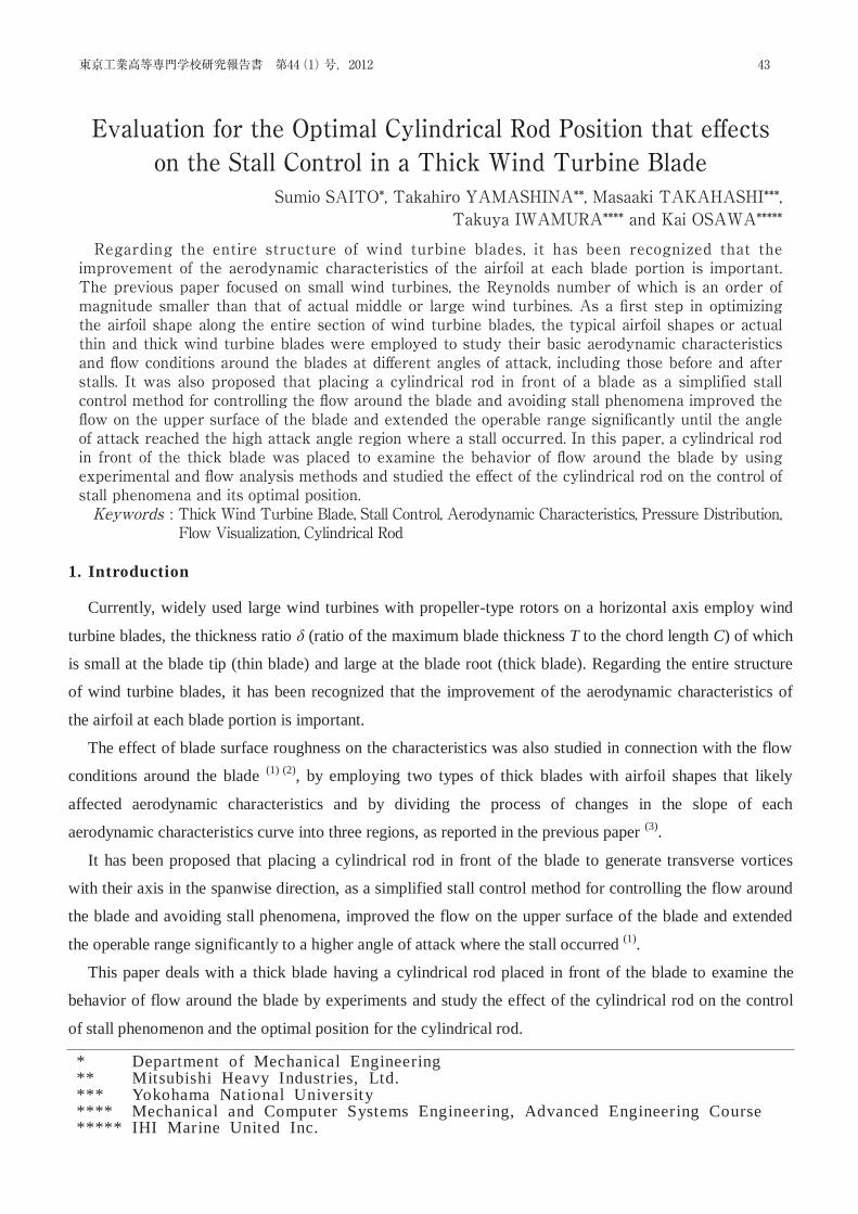
Regarding the ent ire structure of wind turbine blades, it has been recognized that the improvement of the aerodynamic characterist ics of the airfoil at each blade port ion is important. The previous paper focused on small wind turbines, the Reynolds number of which is an order of magnitude smaller than that of actual middle or large wind turbines. As a first step in optimizing the airfoil shape along the ent ir e sect ion of wind turbine blades, the typical airfoil shapes or actual thin and thick wind turbine blades were employed to study their basic aerodynamic characteristics and flow condit ions around the blades at different angles of attack, including those be fore and after stalls. It was also proposed that placing a cylindrical rod in front of a blade as a simplified stall control method for controlling the flow around the blade and avoiding stall phenomena improved the flow on the upper surface of the blade and extended the operable range significantly until the angle of attack reached the high attack angle region where a stall occurred. In this paper, a cylindrical rod in front of the thick blade was placed to examine the behavior of flow around the blade by using experimental and flow analysis methods and studied the effect of the cylindrical rod on the control of stall phenomena and its opt imal posit ion.
(Keywords: Thick Wind Turbine Blade, Stall Control, Aerodynamic Characteristics, Pressure Distribution, Flow Visualization, Cylindrical Rod)
1. Introduction
Currently, widely used large wind turbines with propeller-type rotors on a horizontal axis employ wind
turbine blades, the thickness ratio δ (ratio of the maximum blade thickness T to the chord length C) of which
is small at the blade tip (thin blade) and large at the blade root (thick blade). Regarding the entire structure
of wind turbine blades, it has been recognized that the improvement of the aerodynamic characteristics of
the airfoil at each blade portion is important.
The effect of blade surface roughness on the characteristics was also studied in connection with the flow
conditions around the blade (1) (2), by employing two types of thick blades with airfoil shapes that likely
affected aerodynamic characteristics and by dividing the process of changes in the slope of each
aerodynamic characteristics curve into three regions, as reported in the previous paper (3).
It has been proposed that placing a cylindrical rod in front of the blade to generate transverse vortices
with their axis in the spanwise direction, as a simplified stall control method for controlling the flow around
the blade and avoiding stall phenomena, improved the flow on the upper surface of the blade and extended
the operable range significantly to a higher angle of attack where the stall occurred (1).
This paper deals with a thick blade having a cylindrical rod placed in front of the blade to examine the
behavior of flow around the blade by experiments and study the effect of the cylindrical rod on the control
of stall phenomenon and the optimal position for the cylindrical rod.
* Department of Mechanical Engineering ** Mitsubishi Heavy Industries, Ltd. *** Yokohama Nat ional University **** Mechanical and Computer Systems Engineering, Advanced Engineering Course ***** IHI Marine United Inc.
Evaluation for the Optimal Cylindrical Rod Position that effects on the Stall Control in a Thick Wind Turbine Blade
43東京工業高等専門学校研究報告書 第44(1)号,2012
Regarding the entire structure of wind turbine blades, it has been recognized that the improvement of the aerodynamic characteristics of the airfoil at each blade portion is important. The previous paper focused on small wind turbines, the Reynolds number of which is an order of magnitude smaller than that of actual middle or large wind turbines. As a fi rst step in optimizing the airfoil shape along the entire section of wind turbine blades, the typical airfoil shapes or actual thin and thick wind turbine blades were employed to study their basic aerodynamic characteristics and fl ow conditions around the blades at diff erent angles of attack, including those before and after stalls. It was also proposed that placing a cylindrical rod in front of a blade as a simplified stall control method for controlling the fl ow around the blade and avoiding stall phenomena improved the fl ow on the upper surface of the blade and extended the operable range signifi cantly until the angle of attack reached the high attack angle region where a stall occurred. In this paper, a cylindrical rod in front of the thick blade was placed to examine the behavior of fl ow around the blade by using experimental and fl ow analysis methods and studied the eff ect of the cylindrical rod on the control of stall phenomena and its optimal position.Keywords : Thick Wind Turbine Blade, Stall Control, Aerodynamic Characteristics, Pressure Distribution, Flow Visualization, Cylindrical Rod
Evaluation for the Optimal Cylindrical Rod Position that eff ectson the Stall Control in a Thick Wind Turbine Blade
Sumio SAITO*, Takahiro YAMASHINA**, Masaaki TAKAHASHI***,Takuya IWAMURA**** and Kai OSAWA*****
φ5 [mm]
300 [mm]
2. Experimental apparatus and airfoil shape under test
2.1 Experimental Apparatus
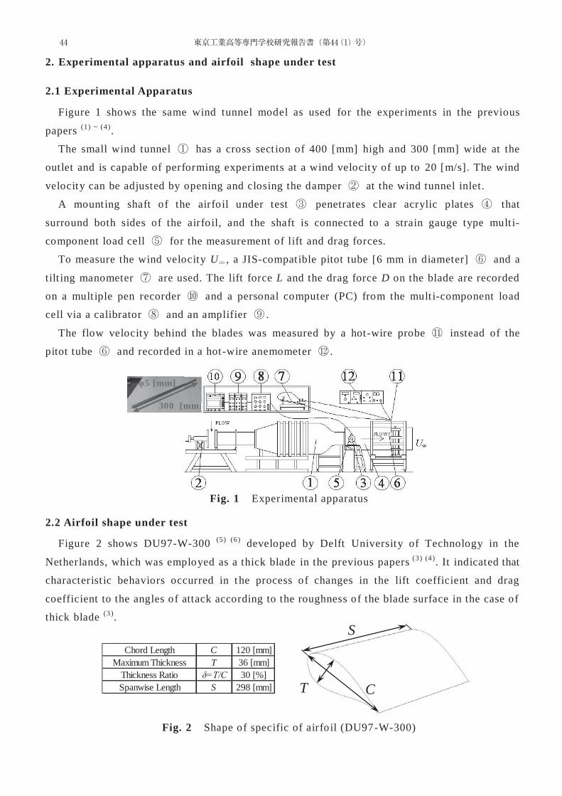
Figure 1 shows the same wind tunnel model as used for the experiments in the previous
papers (1) ~ (4).
The small wind tunnel has a cross sect ion of 400 [mm] high and 300 [mm] wide at the
outlet and is capable of performing experiments at a wind velocity of up to 20 [m/s]. The wind
velocity can be adjusted by opening and closing the damper at the wind tunnel inlet.
A mount ing shaft of the airfoil under test penetrates clear acrylic plates that
surround both sides of the airfoil, and the shaft is connected to a strain gauge type mult i-
component load cell for the measurement of lift and drag forces.
To measure the wind velocity U , a JIS-compat ible pitot tube [6 mm in diameter] and a
tilt ing manometer are used. The lift force L and the drag force D on the blade are recorded
on a mult iple pen recorder and a personal computer (PC) from the mult i-component load
cell via a calibrator and an amplifier .
The flow velocity behind the blades was measured by a hot-wire probe instead of the
pitot tube and recorded in a hot-wire anemometer .
Fig. 1 Experimental apparatus
2.2 Airfoil shape under test
Figure 2 shows DU97-W-300 (5) (6) developed by Delft University of Technology in the
Netherlands, which was employed as a thick blade in the previous papers (3) (4). It indicated that
characterist ic behaviors occurred in t he process of changes in the lift coefficient and drag
coefficient to the angles of attack according to the roughness of the blade surface in the case of
thick blade (3).
Fig. 2 Shape of specific of airfoil (DU97-W-300)
]mm]
C
S
T
Chord Length C 120 [mm]Maximum Thickness T 36 [mm]
Thickness Ratio δ=T/C 30 [%]Spanwise Length S 298 [mm]
44 東京工業高等専門学校研究報告書(第44(1)号)
In this paper, this airfoil shape was employed as the one under test to understand the occurrence
of stall with and without a cylindrical rod and the behavior of flow around the blade. This paper
also examined the effect of the cylindrical rod on the stall control through experiments.
Since the airfoil was made from stereolithography resin, the blade surface has streaky
features, each with a thickness corresponding to the layer width. These streaky features were
polished with sandpaper to finish the surface roughness of the blade to 0. 7 [μm] in the flow
and span direct ions. The airfoil has a thickness ratio δ of 30%, a chord length C of 120 [mm],
and a spanwise length of 298 [mm].
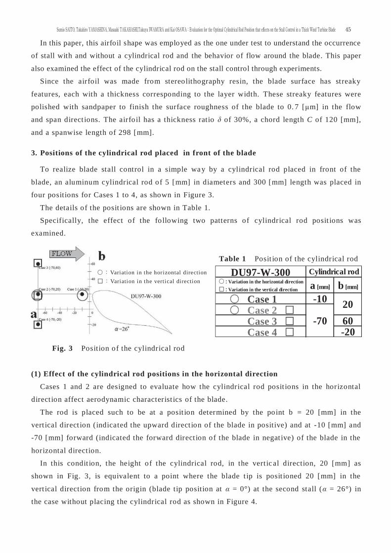
3. Positions of the cylindrical rod placed in front of the blade
To realize blade stall control in a simple wa y by a cylindrical rod placed in front of the
blade, an aluminum cylindrical rod of 5 [mm] in diameters and 300 [mm] length was placed in
four positions for Cases 1 to 4, as shown in Figure 3.
The details of the posit ions are shown in Table 1.
Specifically, the effect of the following two patterns of cylindrical rod posit ions was
examined.
Table 1 Posit ion of the cylindrical rod
Fig. 3 Position of the cylindrical rod
(1) Effect of the cylindrical rod positions in the horizontal direction
Cases 1 and 2 are designed to evaluate how the cylindrical rod posit ions in the horizontal
direct ion affect aerodynamic characterist ics of the blade.
The rod is placed such to be at a posit ion determined by the point b = 20 [mm] in the
vert ical direct ion (indicated the upward direct ion of the blade in positive) and at -10 [mm] and
-70 [mm] forward (indicated the forward direct ion of the blade in negat ive) of the blade in the
horizontal direction.
In this condit ion, the height of the cylindrical rod, in the vert ic al direction, 20 [mm] as
shown in Fig. 3, is equivalent to a point where the blade t ip is posit ioned 20 [mm] in the
vert ical direction from the origin (blade tip position at α = 0°) at the second stall (α = 26°) in
the case without placing the cylindrical rod as shown in Figure 4.
Variation in the horizontal direction Variation in the vertical direction
DU97-W-300Variation in the horizontal directionVariation in the vertical direction
Case 1 Case 2 Case 3 Case 4
a [mm] b [mm]
Cylindrical rod
-20-70
20-10
60
45Sumio SAITO, Takahiro YAMASHINA, Masaaki TAKAHASHI,Takuya IWAMURA and Kai OSAWA:Evaluation for the Optimal Cylindrical Rod Position that eff ects on the Stall Control in a Thick Wind Turbine Blade
(2) Effect of the cylindrical rod positions in the vertical direction
To evaluate how the cylindrical rod posit ions in the vertical direction affect aerodynamic
characterist ics of the blade, together with Case 2, Cases 3 and 4 fix the forward horizontal
point a = -70 [mm] and place the cylindrical rod to a posit ion 20 [mm] (Case 2), 60
[mm] (Case 3), and -20 [mm] (Case 4) in the vertical direction, respect ively.
4. Characteristics of “DU97-W-300” with the cylindrical rod placed in front of the blade
4.1 Variation in horizontal positions of the cylindrical rod (Case1 and 2)
(a) Aerodynamic characteristics of “DU97-W-300”
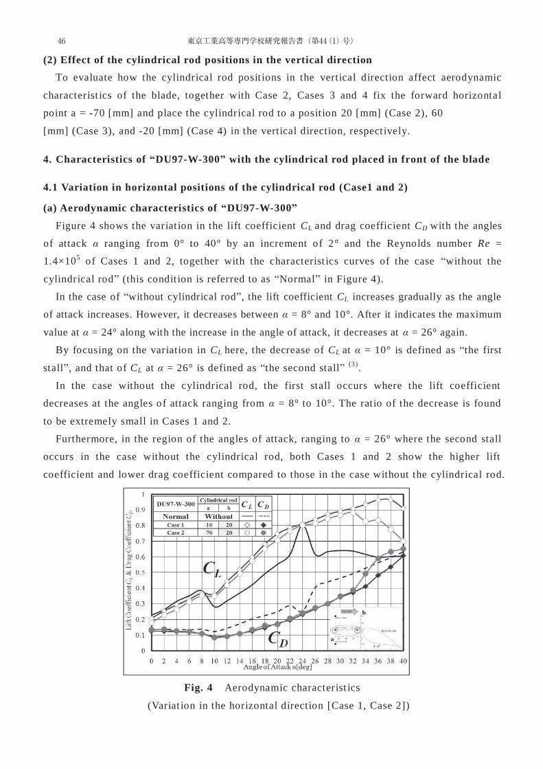
Figure 4 shows the variat ion in the lift coefficient CL and drag coefficient CD with the angles
of attack α ranging from 0° to 40° by an increment of 2° and the Reynolds number Re =
1.4×10⁵ of Cases 1 and 2, together with the characterist ics curves of the case “without the
cylindrical rod” (this condit ion is referred to as “Normal” in Figure 4).
In the case of “without cylindrical rod”, the lift coefficient CL increases gradually as the angle
of attack increases. However, it decreases between α = 8° and 10°. After it indicates the maximum
value at α = 24° along with the increase in the angle of attack, it decreases at α = 26° again.
By focusing on the variation in CL here, the decrease of CL at α = 10° is defined as “the first
stall”, and that of CL at α = 26° is defined as “the second stall” (3).
In the case without the cylindrical rod, the first stall occurs where the lift coefficient
decreases at the angles of attack ranging from α = 8° to 10°. The ratio of the decrease is found
to be extremely small in Cases 1 and 2.
Furthermore, in the region of the angles of attack, ranging to α = 26° where the second stall
occurs in the case without the cylindrical rod, both Cases 1 and 2 show the higher lift
coefficient and lower drag coefficient compared to those in the case without the cylindrical rod.
Fig. 4 Aerodynamic characterist ics
(Variat ion in the horizontal direction [Case 1, Case 2])
46 東京工業高等専門学校研究報告書(第44(1)号)
Also in Cases 1 and 2, the lift force does not decrease at α = 26°, and the lift coefficient and
drag coefficient cont inue to gradually increase. It can be observed that the second stall occurs
at α = 34° in Case 2 and at α = 40° in Case 1, respect ively.
As observed above, how the variat ion in horizontal posit ion of the cylindrical rod effects on
aerodynamic characterist ics of the blade was studied by maintaining the point b = 20 [mm] in
the vertical direct ion, and it was clarified that the variat ion remarkably improved the first and
second blade stall control, and the control was even better when placing the cylindrical rod to
a posit ion closer to the blade t ip.
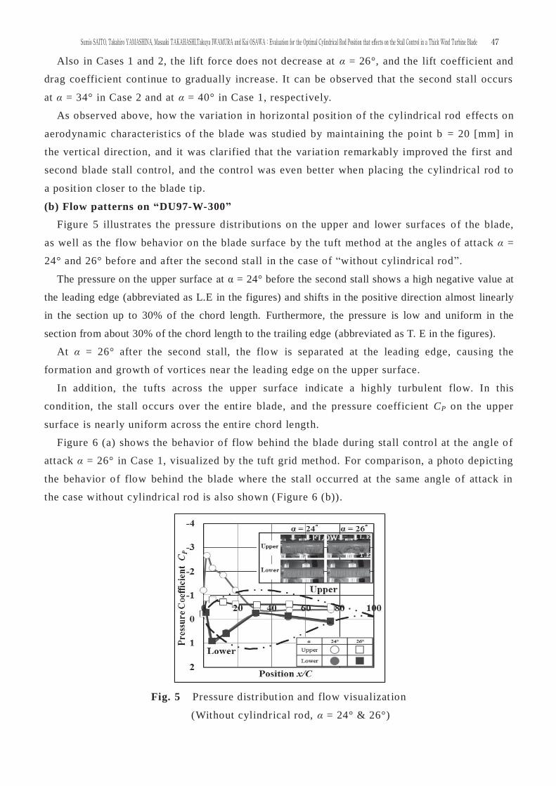
(b) Flow patterns on “DU97-W-300”
Figure 5 illustrates the pressure distribut ions on the upper and lower surfaces of the blade,
as well as the flow behavior on the blade surface by the tuft method at the angles of attack α =
24° and 26° before and after the second stall in the case of “without cylindrical rod”.
The pressure on the upper surface at α = 24° before the second stall shows a high negative value at
the leading edge (abbreviated as L.E in the figures) and shifts in the positive direction almost linearly
in the section up to 30% of the chord length. Furthermore, the pressure is low and uniform in the
section from about 30% of the chord length to the trailing edge (abbreviated as T. E in the figures).
At α = 26° after the second stall, the flow is separated at the leading edge, causing the
format ion and growth of vortices near the leading edge on the upper surface.
In addition, the tufts across the upper surface indicate a highly turbulent flow. In this
condit ion, the stall occurs over the ent ire blade, and the pressure coefficient CP on the upper
surface is nearly uniform across the ent ire chord length.
Figure 6 (a) shows the behavior of flow behind the blade during stall control at the angle of
attack α = 26° in Case 1, visualized by the tuft grid method. For comparison, a photo depict ing
the behavior of flow behind the blade where the stall occurred at the same angle of attack in
the case without cylindrical rod is also shown (Figure 6 (b)).
Fig. 5 Pressure distribut ion and flow visualizat ion
(Without cylindrical rod, α = 24° & 26°)
47Sumio SAITO, Takahiro YAMASHINA, Masaaki TAKAHASHI,Takuya IWAMURA and Kai OSAWA:Evaluation for the Optimal Cylindrical Rod Position that eff ects on the Stall Control in a Thick Wind Turbine Blade
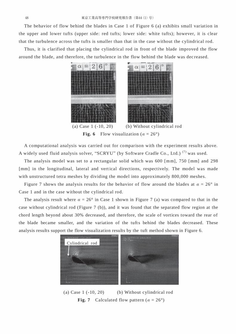
The behavior of flow behind the blades in Case 1 of Figure 6 (a) exhibits small variat ion in
the upper and lower tufts (upper side: red tufts; lower side: white tufts); however, it is clear
that the turbulence across the tufts is smaller than that in the case without the cylindrical rod.
Thus, it is clarified that placing the cylindrical rod in front of the blade improved the flow
around the blade, and therefore, the turbulence in the flow behind the blade was dec reased.
(a) Case 1 (-10, 20) (b) Without cylindrical rod
Fig. 6 Flow visualizat ion (α = 26°)
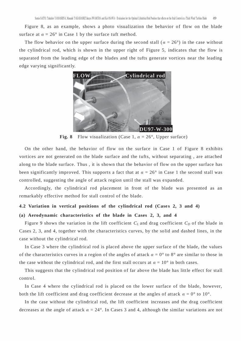
A computational analysis was carried out for comparison with the experiment results above.
A widely used fluid analysis solver, “SCRYU” (by Software Cradle Co., Ltd.) (7) was used.
The analysis model was set to a rectangular solid which was 600 [mm], 750 [mm] and 298
[mm] in the longitudinal, lateral and vert ical direct ions, respect ively. The model was made
with unstructured tetra meshes by dividing the model into approximately 800,000 meshes.
Figure 7 shows the analysis results for the behavior of flow around the blades at α = 26° in
Case 1 and in the case without the cylindrical rod.
The analysis result where α = 26° in Case 1 shown in Figure 7 (a) was compared to that in the
case without cylindrical rod (Figure 7 (b)), and it was found that the separated flow region at the
chord length beyond about 30% decreased, and therefore, the scale of vortices toward the rear of
the blade became smaller, and the variation of the tuft s behind the blades decreased. These
analysis results support the flow visualization results by the tuft method shown in Figure 6.
(a) Case 1 (-10, 20) (b) Without cylindrical rod
Fig. 7 Calculated flow pattern (α = 26°)
Cylindrical rod
48 東京工業高等専門学校研究報告書(第44(1)号)
FLOW Cylindrical rod
DU97-W-300
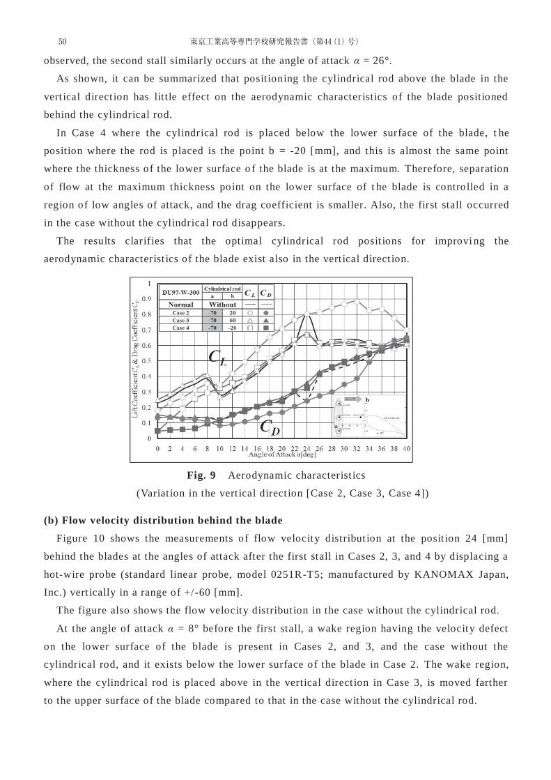
Figure 8, as an example, shows a photo visualizat ion the behavior of flow on the blade
surface at α = 26° in Case 1 by the surface tuft method.
The flow behavior on the upper surface during the second stall (α = 26°) in the case without
the cylindrical rod, which is shown in the upper right of Figure 5, indicates that the flow is
separated from the leading edge of the blades and the tufts generate vort ices near the leading
edge varying significant ly.
Fig. 8 Flow visualizat ion (Case 1, α = 26°, Upper surface)
On the other hand, the behavior of flow on the surface in Case 1 of Figure 8 exhibits
vort ices are not generated on the blade surface and the tufts, without separat ing , are attached
along to the blade surface. Thus , it is shown that the behavior of flow on the upper surface has
been significant ly improved. This supports a fact that at α = 26° in Case 1 the second stall was
controlled, suggest ing the angle of attack region unt il the stall was expanded.
Accordingly, the cylindrical rod placement in front of the blade was presented as an
remarkably effective method for stall control of the blade.
4.2 Variation in vertical positions of the cylindrical rod (Case s 2, 3 and 4)
(a) Aerodynamic characteristics of the blade in Cases 2, 3, and 4
Figure 9 shows the variation in the lift coefficient CL and drag coefficient CD of the blade in
Cases 2, 3, and 4, together with the characterist ics curves, by the solid and dashed lines, in the
case without the cylindrical rod.
In Case 3 where the cylindrical rod is placed above the upper surface of the blade, the values
of the characteristics curves in a region of the angles of attack α = 0° to 8° are similar to those in
the case without the cylindrical rod, and the first stall occurs at α = 10° in both cases.
This suggests that the cylindrical rod posit ion of far above the blade has litt le effect for stall
control.
In Case 4 where the cylindrical rod is placed on the lower surface of the blade, however,
both the lift coefficient and drag coefficient decrease at the angles of attack α = 0° to 10°.
In the case without the cylindrical rod, the lift coefficient increases and the drag coefficient
decreases at the angle of attack α = 24°. In Cases 3 and 4, although the similar variat ions are not
49Sumio SAITO, Takahiro YAMASHINA, Masaaki TAKAHASHI,Takuya IWAMURA and Kai OSAWA:Evaluation for the Optimal Cylindrical Rod Position that eff ects on the Stall Control in a Thick Wind Turbine Blade
observed, the second stall similarly occurs at the angle of attack α = 26°.
As shown, it can be summarized that positioning the cylindrical rod above the blade in the
vert ical direct ion has little effect on the aerodynamic characteristics of the blade positioned
behind the cylindrical rod.
In Case 4 where the cylindrical rod is placed below the lower surface of the blade, t he
position where the rod is placed is the point b = -20 [mm], and this is almost the same point
where the thickness of the lower surface o f the blade is at the maximum. Therefore, separation
of flow at the maximum thickness point on the lower surface of t he blade is controlled in a
region of low angles of attack, and the drag coefficient is smaller. Also, the first stall occurred
in the case without the cylindrical rod disappears.
The results clarifies that the optimal cylindrical rod posit ions for improvi ng the
aerodynamic characterist ics of the blade exist also in the vert ical direct ion.
Fig. 9 Aerodynamic characterist ics
(Variat ion in the vert ical direct ion [Case 2, Case 3, Case 4])
(b) Flow velocity distribution behind the blade
Figure 10 shows the measurements of flow velocity distribut ion at the posit ion 24 [mm]
behind the blades at the angles of attack after the first stall in Cases 2, 3, and 4 by displacing a
hot-wire probe (standard linear probe, model 0251R-T5; manufactured by KANOMAX Japan,
Inc.) vert ically in a range of +/-60 [mm].
The figure also shows the flow velocity distribut ion in the case without the cylindrical rod.
At the angle of attack α = 8° before the first stall, a wake region having the velocity defect
on the lower surface of the blade is present in Cases 2, and 3, and the case without the
cylindrical rod, and it exists below the lower surface of the blade in Case 2. The wake region,
where the cylindrical rod is placed above in the vertical direct ion in Case 3, is moved farther
to the upper surface of the blade compared to that in the case without the cylindrical rod.
50 東京工業高等専門学校研究報告書(第44(1)号)
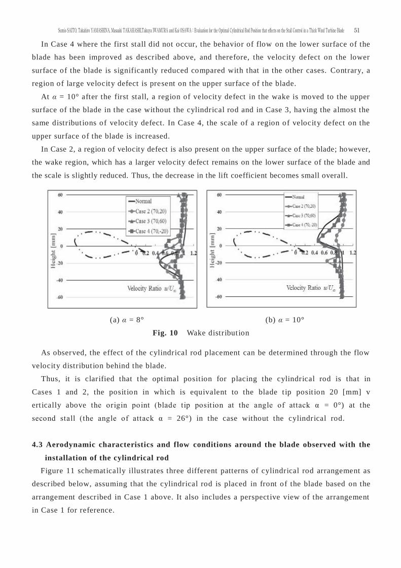
In Case 4 where the first stall did not occur, the behavior of flow on the lower surface of the
blade has been improved as described above, and therefore, the velocity defect on the lower
surface of the blade is significant ly reduced compared with that in the other cases. Contrary, a
region of large velocity defect is present on the upper surface of the blade.
At α = 10° after the first stall, a region of velocity defect in the wake is moved to the upper
surface of the blade in the case without the cylindrical rod and in Case 3, having the almost the
same distribut ions of velocity defect. In Case 4, the scale of a region of velocity defect on the
upper surface of the blade is increased.
In Case 2, a region of velocity defect is also present on the upper surface of the blade; however,
the wake region, which has a larger velocity defect remains on the lower surface of the blade and
the scale is slightly reduced. Thus, the decrease in the lift coefficient becomes small overall.
(a) α = 8° (b) α = 10°
Fig. 10 Wake distribut ion
As observed, the effect of the cylindrical rod placement can be determined through the flow
velocity distribut ion behind the blade.
Thus, it is clarified that the opt imal position for placing the cylindrical rod is that in
Cases 1 and 2, the posit ion in which is equivalent to the blade t ip posit ion 20 [mm] v
ert ically above the origin point (blade tip posit ion at the angle of attack α = 0°) at the
second stall (the angle of attack α = 26°) in the case without the cylindrical rod.
4.3 Aerodynamic characteristics and flow conditions around the blade observed with the
installation of the cylindrical rod
Figure 11 schematically illustrates three different patterns of cylindrical rod arrangement as
described below, assuming that the cylindrical rod is placed in front of the blade based on the
arrangement described in Case 1 above. It also includes a perspect ive view of the arrangement
in Case 1 for reference.
51Sumio SAITO, Takahiro YAMASHINA, Masaaki TAKAHASHI,Takuya IWAMURA and Kai OSAWA:Evaluation for the Optimal Cylindrical Rod Position that eff ects on the Stall Control in a Thick Wind Turbine Blade
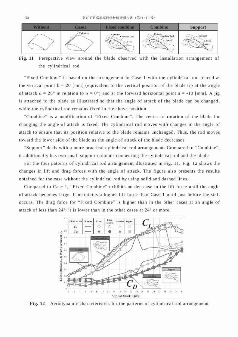
Fig. 11 Perspective view around the blade observed with the installat ion arrangement of
the cylindrical rod
“Fixed Combine” is based on the arrangement in Case 1 with the cylindrical rod placed at
the vertical point b = 20 [mm] (equivalent to the vert ical posit ion of the blade t ip at the a ngle
of attack α = 26° in relat ion to α = 0°) and at the forward horizontal point a = -10 [mm]. A jig
is attached to the blade as illustrated so that the angle of attack of the blade can be changed ,
while the cylindrical rod remains fixed in t he above posit ion.
“Combine” is a modificat ion of “Fixed Combine”. The center of rotation of the blade for
changing the angle of attack is fixed. The cylindrical rod moves with changes in the angle of
attack to ensure that its posit ion relat ive to the blade remains unchanged. Thus, the rod moves
toward the lower side of the blade as the angle o f attack of the blade decreases.
“Support” deals with a more pract ical cylindrical rod arrangement. Compared to “Combine”,
it addit ionally has two small support columns connect ing the cylindrical rod and the blade.
For the four patterns of cylindrical rod arrangement illustrated in Fig. 11, Fig. 12 shows the
changes in lift and drag forces with the angle of attack. The figure also presents the results
obtained for the case without the cylindrical rod by using solid and dashed lines.
Compared to Case 1, “Fixed Combine” exhibits no decrease in the lift force unt il the angle
of attack becomes large. It maintains a higher lift force than Case 1 until just before the stall
occurs. The drag force for “Fixed Combine” is higher than in the other cases at an angle of
attack of less than 24º; it is lower than in the other cases at 24º or more.
Fig. 12 Aerodynamic characterist ics for the patterns of cylindrical rod arrangement
Without Case1 Fixed combine Combine Support
52 東京工業高等専門学校研究報告書(第44(1)号)
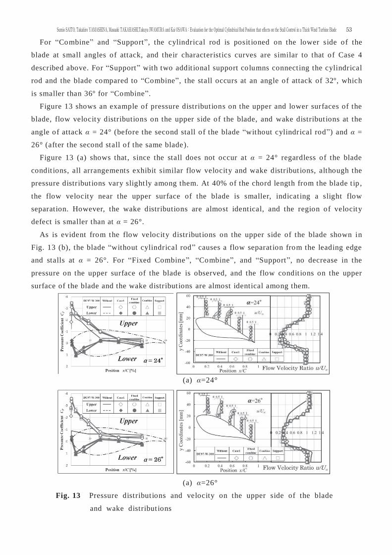
For “Combine” and “Support”, the cylindrical rod is posit ioned on the lower side of the
blade at small angles of attack, and their characteristics curves are similar to that of Case 4
described above. For “Support” with two addit ional support columns connecting the cylindrical
rod and the blade compared to “Combine”, the stall occurs at an angle of attack of 32º, which
is smaller than 36º for “Combine”.
Figure 13 shows an example of pressure distribut ions on the upper and lower surfaces of the
blade, flow velocity distributions on the upper side of the blade, and wake distribut ions at the
angle of attack α = 24° (before the second stall of the blade “without cylindrical rod”) and α =
26° (after the second stall of the same blade).
Figure 13 (a) shows that , since the stall does not occur at α = 24° regardless of the blade
condit ions, all arrangements exhibit similar flow velocity and wake distribut ions, although the
pressure distribut ions vary slight ly among them. At 40% of the chord length from the blade t ip ,
the flow velocity near the upper surface of the blade is smaller, indicat ing a slight flow
separation. However, the wake distributions are almost identical, and the region of velocity
defect is smaller than at α = 26°.
As is evident from the flow velocity distribut ions on the upper side of the blade shown in
Fig. 13 (b), the blade “without cylindrical rod” causes a flow separat ion from the leading edge
and stalls at α = 26°. For “Fixed Combine”, “Combine”, and “Support”, no decrease in the
pressure on the upper surface of the blade is observed, and the flow condit ions on the upper
surface of the blade and the wake distribut ions are almost identical among them.
(a) α=24°
(a) α=26°
Fig. 13 Pressure distribut ions and velocity on the upper side of the blade
and wake distribut ions
53Sumio SAITO, Takahiro YAMASHINA, Masaaki TAKAHASHI,Takuya IWAMURA and Kai OSAWA:Evaluation for the Optimal Cylindrical Rod Position that eff ects on the Stall Control in a Thick Wind Turbine Blade

5. Conclusions
Among the airfoils used for wind turbines, a thick blade having an airfoil shape likely
affected the aerodynamic characterist ics was studied, by examining the be havior of flow
around the blade by placing a cylindrical rod in front of the blade in experiments and analyzed
with a flow analysis method, and the effect of the cylindrical rod on the stall phenomenon
control and the optimal posit ion for placing the cylindrical rod were evaluated.
This study has yielded the following findings.
(1) Placing a cylindrical rod in front of the blade affects the aerodynamic characterist ics of the
airfoil posit ioned behind the rod, and the placement significant ly extends the operable range
to a higher angle of attack that causes the second stall.
(2) The optimal posit ion for placing the cylindrical rod is that in Cases 1 and 2, the position
which is equivalent to the blade t ip posit ion 20 [mm] vert ically above the origin point (blade
tip posit ion at the angle of attack α = 0°) at the second stall (the angle of attack α = 26°) in
the case without the cylindrical rod.
(3) The cylindrical rod position in the vert ical direct ion has less effect on the stall control as it
is farther above or below from the blade center line.
(4) Assuming that the cylindrical rod was placed in front of the blade, three different patterns
of cylindrical rod arrangement denoted as “Fixed Combine”, “Combine”, and “Support” were
proposed. Their effect iveness in stall control was demonstrated by clarifying t heir
aerodynamic characterist ics and flow condit ions.
Nomenclature
A Blade surface area = 3.58 × 10⁻² [m2] D Drag force [N]
CD Drag coefficient )21( 2 AUD
L Lift force [N]
PS Static pressure [Pa]
CL Lift coefficient )21( 2 AUL
U∞ Flow velocity [m/s]
α Angle of attack [°]
CP Pressure coefficient )21( 2UPS
ρ Air density [kg/m3]
References
[1] Saito, S. & Yamashina, T., Evaluat ion of Aerodynamic Characterst ics of Two Differenct
Thick Blades Used as Wind Turbines Airfoils and One Trial of Stall Contorol, Research
Reports of Tokyo National College of Technology , No. 42 (1), 2010, pp. 35-43.
54 東京工業高等専門学校研究報告書(第44(1)号)
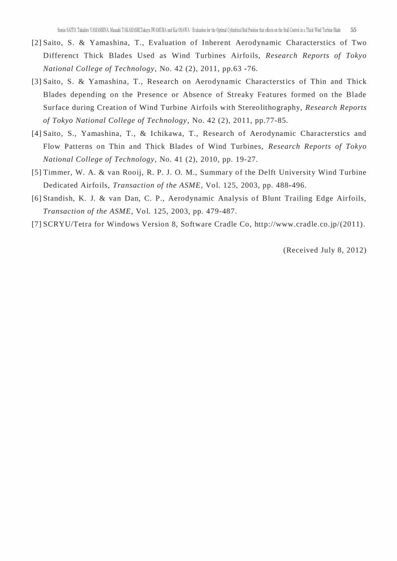
[2] Saito, S. & Yamashina, T., Evaluation of Inherent Aerodynamic Characterstics of Two
Differenct Thick Blades Used as Wind Turbines Airfoils, Research Reports of Tokyo
National College of Technology, No. 42 (2), 2011, pp.63 -76.
[3] Saito, S. & Yamashina, T., Research on Aerodynamic Characterst ics of Thin and Thick
Blades depending on the Presence or Absence of Streaky Features formed on the Blade
Surface during Creat ion of Wind Turbine Airfoils with Stereolithography, Research Reports
of Tokyo National College of Technology , No. 42 (2), 2011, pp.77-85.
[4] Saito, S., Yamashina, T., & Ichikawa, T., Research of Aerodynamic Characterstics and
Flow Patterns on Thin and Thick Blades of Wind Turbines, Research Reports of Tokyo
National College of Technology, No. 41 (2), 2010, pp. 19-27.
[5] Timmer, W. A. & van Rooij, R. P. J. O. M., Summary of the Delft University Wind Turbine
Dedicated Airfoils, Transaction of the ASME, Vol. 125, 2003, pp. 488-496.
[6] Standish, K. J. & van Dan, C. P., Aerodynamic Analysis of Blunt Trailing Edge Airfoils,
Transaction of the ASME, Vol. 125, 2003, pp. 479-487.
[7] SCRYU/Tetra for Windows Version 8, Software Cradle Co, http://www.cradle.co.jp/(2011).
(Received July 8, 2012)
55Sumio SAITO, Takahiro YAMASHINA, Masaaki TAKAHASHI,Takuya IWAMURA and Kai OSAWA:Evaluation for the Optimal Cylindrical Rod Position that eff ects on the Stall Control in a Thick Wind Turbine Blade

56 東京工業高等専門学校研究報告書(第44(1)号)
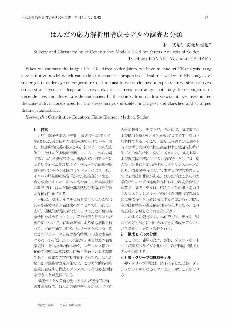
* **
Survey and Classification of Constitutive Models Used for Stress Analysis of Solder Takeharu HAYASHI Yoshinori EBIHARA
When we estimate the fatigue life of lead-free solder joints, we have to conduct FE
analysis using a constitutive model which can exhibit mechanical properties of lead-free solder. In FE analysis of solder joints under cyclic temperature load, a constitutive model has to express stress strain curves, stress strain hysteresis loops and stress relaxation curves accurately, containing these temperature dependencies and these rate dependencies. In this study, from such a viewpoint, we investigated the constitutive models used for the stress analysis of solder in the past and classified and arranged them systematically.
Keywords : Constitutive Equation, Finite Element Method, Solder
* **
57東京工業高等専門学校研究報告書 第44(1)号,2012
When we estimate the fatigue life of lead-free solder joints, we have to conduct FE analysis using a constitutive model which can exhibit mechanical properties of lead-free solder. In FE analysis of solder joints under cyclic temperature load, a constitutive model has to express stress strain curves, stress strain hysteresis loops and stress relaxation curves accurately, containing these temperature dependencies and these rate dependencies. In this study, from such a viewpoint, we investigated the constitutive models used for the stress analysis of solder in the past and classifi ed and arranged them systematically.Keywords : Constitutive Equation, Finite Element Method, Solder
はんだの応力解析用構成モデルの調査と分類林 丈晴*,海老原理徳**
Survey and Classifi cation of Constitutive Models Used for Stress Analysis of SolderTakeharu HAYAHI, Yoshinori EBIHARA
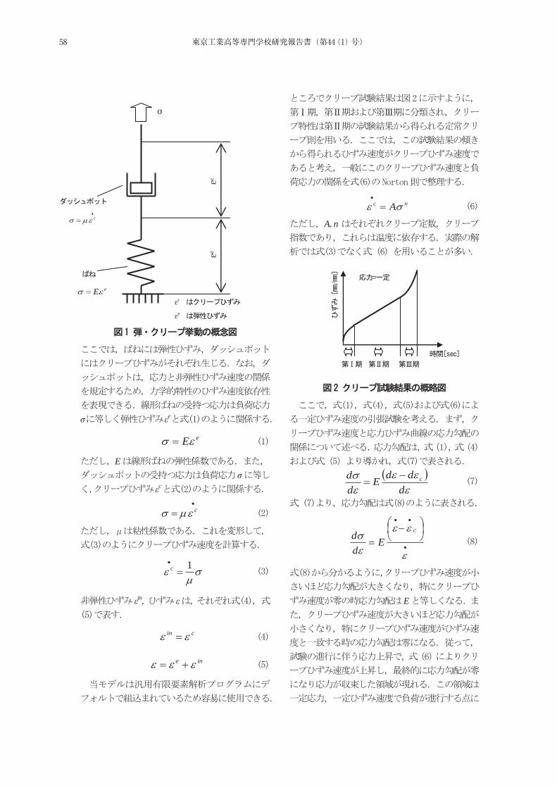
σ εe
eE
Eσ
εc
c
1c
εin ε
cin
ine
nc A
A n
dddE
dd c
c
Edd
E
σ
εcεe
c
eEεc
εe
58 東京工業高等専門学校研究報告書(第44(1)号)
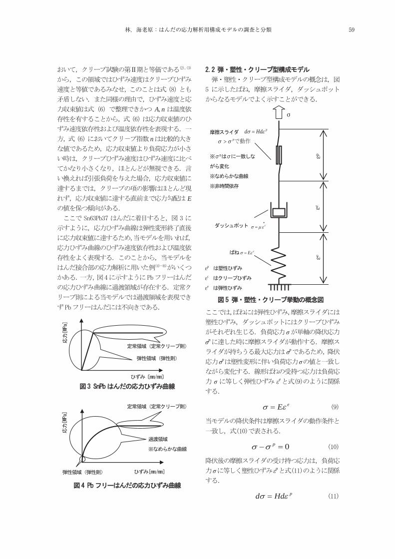
A n
n
E
σσp
σp
σp σ
σ εe
eE
0p
σ εp
pHdd
εp
εc
εe
σ
εpεc
εe
pHddp
eE
c
59林,海老原:はんだの応力解析用構成モデルの調査と分類
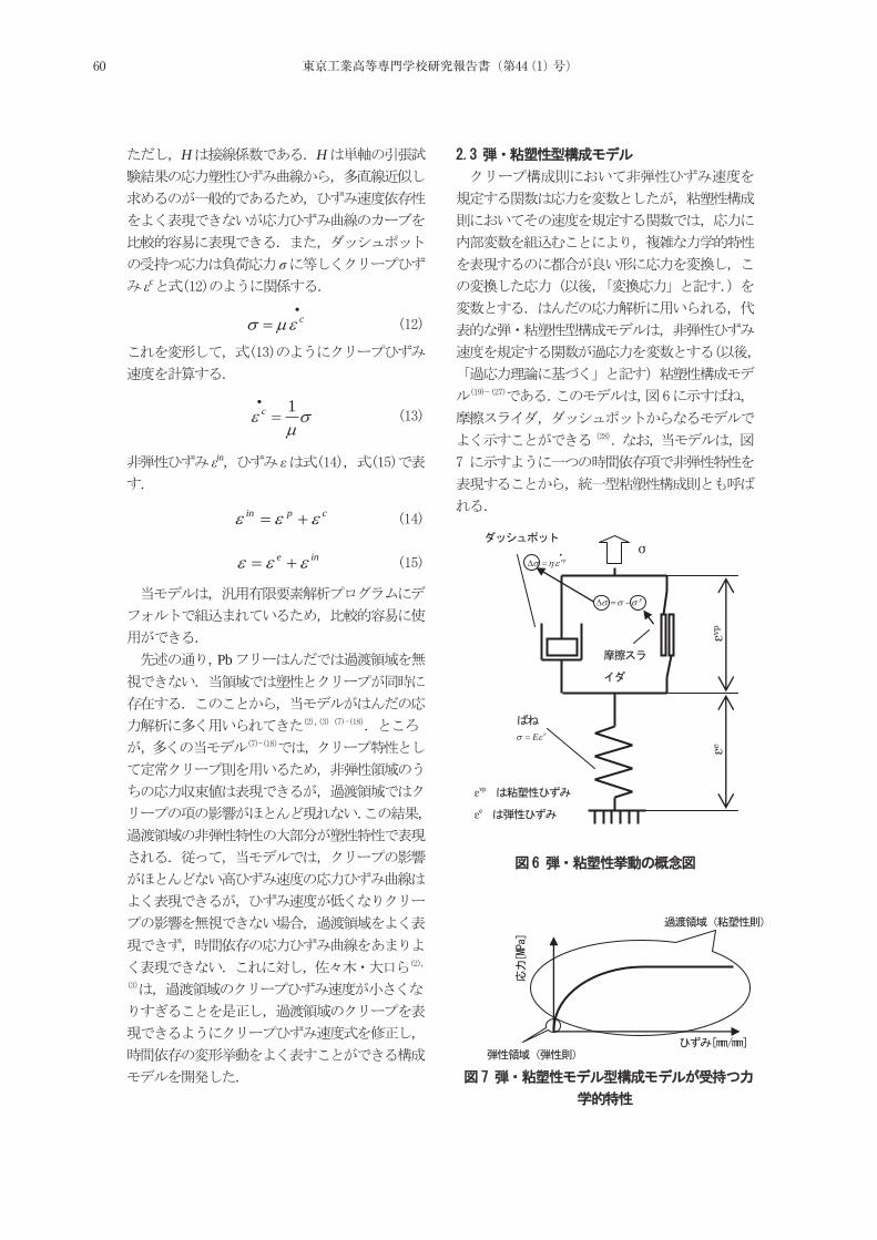
H H
σεc
c
1c
εin ε
cpin
ine
Pb
εvpεe
σ
vp
p
eE
εvp
εe
60 東京工業高等専門学校研究報告書(第44(1)号)
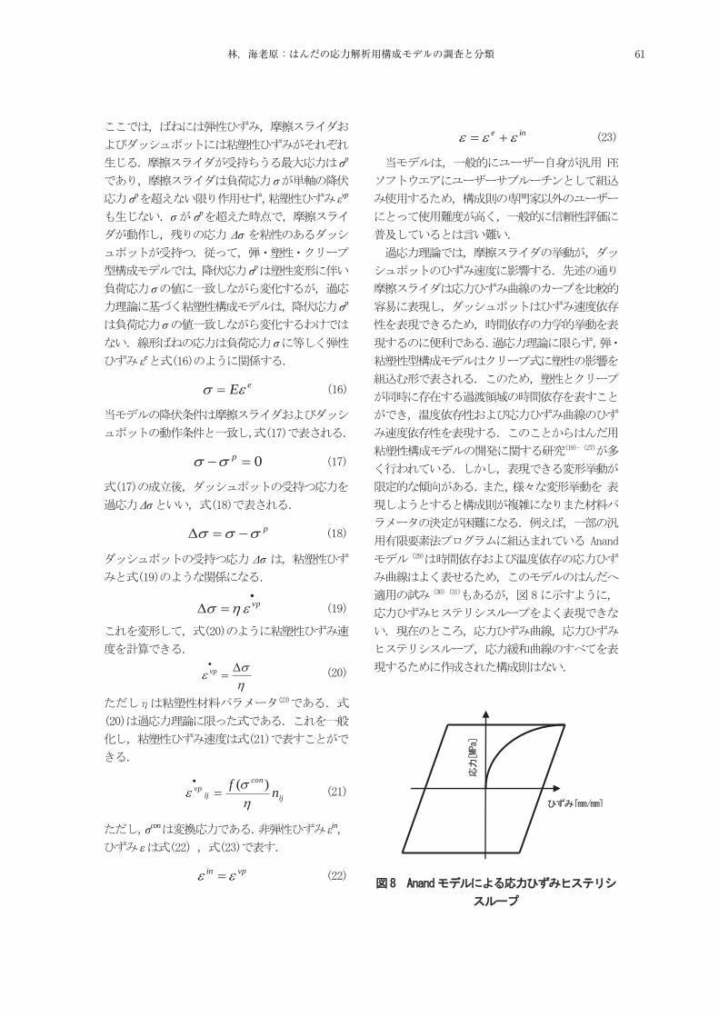
σp
σσp εvp
σ σp
Δσ
σp
σσp
σσ
εe
eE
0p
Δσ
p
Δσ
vp
vp
ij
con
ijvp nf )(
σcon εin
ε
vpin
ine
61林,海老原:はんだの応力解析用構成モデルの調査と分類
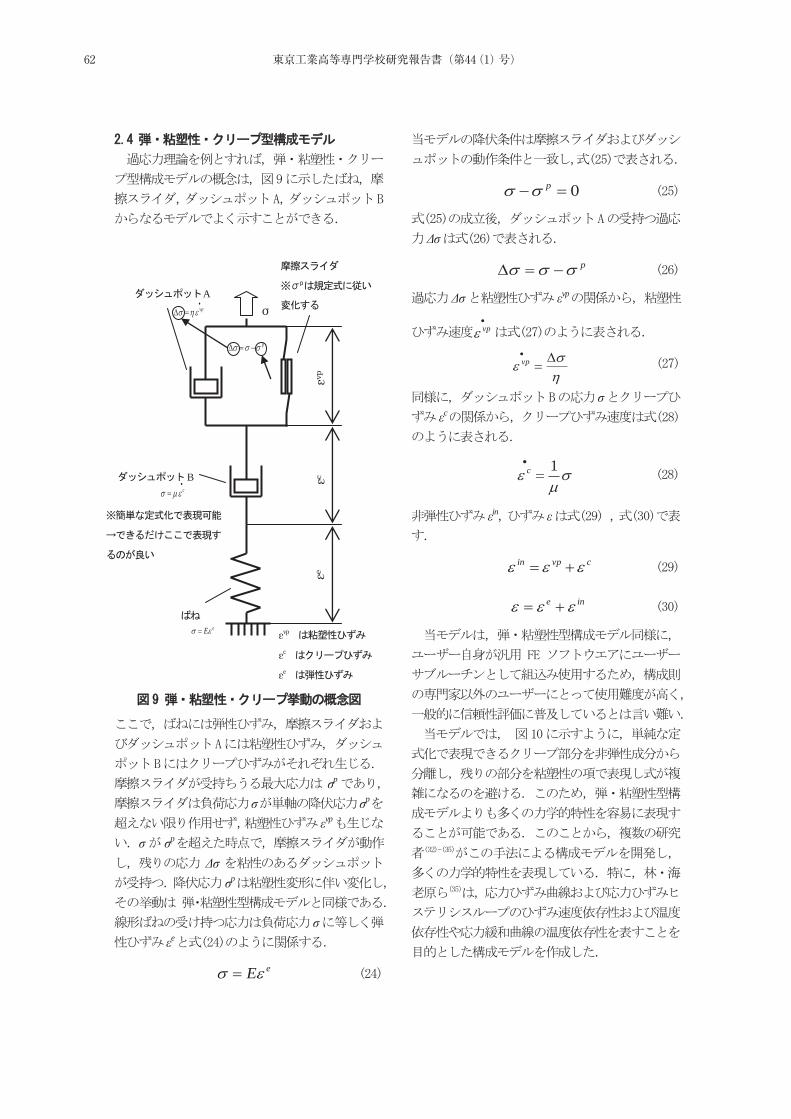
σp
σ σp
εvp
σ σp
Δσσp
σεe
eE
0p
Δσ
p
Δσ εvp
vp
vp
σεc
1c
εin ε
cvpin
ine
εvp
εc
εe
σεvp
εcεe
Bc
Avp
p
eE
62 東京工業高等専門学校研究報告書(第44(1)号)
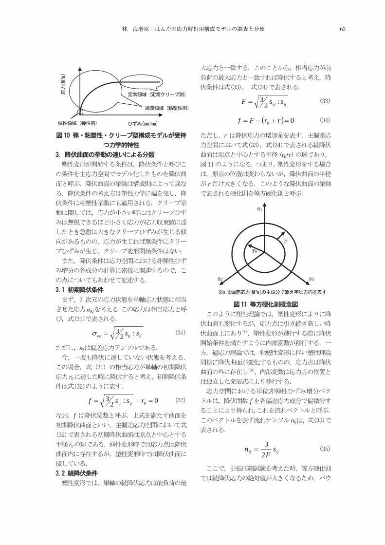
σeq
ijijeq ss :23
sij
r0
0:23
0rssf ijij
f
r0
ijij ssF :23
00 rrFf
r
r0 r
r
f
nij
ijij sF
n23
r r0
s3
s1
s2
63林,海老原:はんだの応力解析用構成モデルの調査と分類
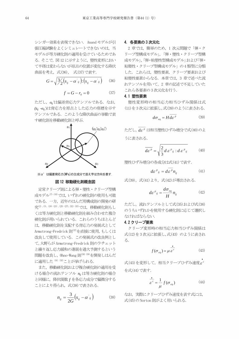
ijijijij ssG '' :23
00rGf
αij’(sij -αij’)
nij
f
ijijij sG
n '
23
peq dHd
pd
ijp
ijpp ddd :
32
ijp
ijp ndd
ijeq
ijp n
Hd
d
ceqf )(
c
)(1eq
c f
s1
s2 s3
r0
(α1’α2’α3’
64 東京工業高等専門学校研究報告書(第44(1)号)
neq
c A
f=F-0f
ijn
eqijc
ijc sAn )1(
23
vpvpeqf
Δσeqvp
)( vpeqvp f
ij
vpeq
ijvp n
f )(
ij
coneq
ijvp n
f )(
σeqcon
65林,海老原:はんだの応力解析用構成モデルの調査と分類
(2000)pp.6-79.
Vol. 68 No. 673(2002-9), pp. 1328-1335.
Vol. 69 No. 682(2003-6) pp. 980-987.
Vol. 65 No. 636(1998-8) pp. 1690-1695.
(1991.11 ) pp.223-224.
Vol. 31 No. 4(1996-12) pp. 43-52.
14th Symposium on Microjoining and Assembly Technology in Electronics(2008-2) pp.129-134.
14th Symposium on Microjoining and Assembly Technology in Electronics(2008-2) pp.241-246.
Vol. 62 No. 594(1996-2) pp. 527-532.
(2007-3) pp.161-162
(2007-05) pp.123-124
Vol.4 No.4
(2001-7) pp. 262-266.
(2000-10) pp.521-522.
Vol. 67No. 654(2001-2) pp. 216-224.
Vol. 32 No. 4(2006-7) pp. 219-225.
Vol.1, No.4 (1998-9) pp. 278-283.
Vol. 64 No. 619(1998-3) pp. 550-557.
Vol. 64 No. 619(1998-3) pp. 558-563.
McDowell, D.L., Miller, M.P., and Brooks, D.C., “AUnified Creep-Plasticity Theory for Solder Alloy”, Fatigue of Electronic Materials, ASTM STP 1153(1994) , S. A. Schroeder and M. R. Mitchell, eds., American Society for Testing and Materials, Philadelphia, pp. 42-59.
Maciucescu, L.T., Sham, -L., and Krempl, E., “Modeing the Defomation Behavior of a Sn-Pb Soler Alloy Using the Simplified Viscoplasticity Theory Based on Overstress(VBO) ”,
66 東京工業高等専門学校研究報告書(第44(1)号)
Transactions of the ASME, Journal of Electronic Packaging, Vol. 121(1999), pp. 92-98.
Tang, H., and Basaran, C., “Damage Mechanics-Based Fatigue Life Prediction Model for Solder Joints”, Transactions of the ASME, Journal of Electronic Packaging, Vol. 125(2003), pp. 120-125.
Basaran, C., Zhao, Y., Tang, H., and Gomez, J., “A Damage Mechanics-Based Constitutive Model for Solder Joints”, Transactions of the ASME, Journal of Electronic Packaging, Vol. 127(2005), pp. 208-214.
Gomez, J., and Basaran, C., “Damage mechanics constitutive model for Pb/Sn solder joints incorporating nonlinear kinematic hardening and rate dependent effects using a return mapping integration algorithm”, Mechanics of Materials, Vol. 38(2006), pp. 585-598.
Stolkarts, V., Keer, L.M., and Fine, M.E., “Constitutive and Cyclic Damage Model of 63Sn-37Pb Solder”, Transactions of the ASME, Journal of Electronic Packaging, Vol. 123(2001), pp.351-355.
Busso, E.P., Kitano, M., and Kumazawa, T., “A Visco-plastic Constitutive Model for 60/40 Tin-lead Solder Used in IC Package Joints”, Journal ofEngineering Materials and Technology, Vol. 114(1992), pp. 331-337.
Sung, Y., Luo, G., and Chian, K.S., “A Viscoplastic Constitutive Model for 63Sn37Pb Eutectic Solders”, Transactions of the ASME, Journal of Electronic Packaging, Vol. 124(2002), pp. 91-96.
Fossum, A.F., Vianco, P.T., Neilsen, M.K., and Pierce, D.M., “A Plactical Viscoplastic Damage Model for Lead-free Solder”, Transactions of the ASME, Journal of Electronic Packaging, Vol. 128(2006), pp. 71-81.
(1988)
pp.96-99. Anand, L., “ Constitutive Equation for the
Rate-Dependent Deformation of Metals at Elevated Temperatures”, Transactions of the
ASME, Journal of Electronic Packaging, Vol.104(1982), pp. 12-17.
Vol.7 No1 (2004-1) pp.76-81.
(2002-10), pp.775-776.
Vol. 72, No. 720 (2006-8), pp. 1161-1168.
Sasaki, K., Ohguchi, K., and Ishikawa, H., “Viscoplastic Defomation of 40Pb/60Sn Solder Alloys - Experiments and Constitutive Modeling”, Transactions of the ASME, Journal of Electronic Packaging, Vol. 123(2001), pp. 379-387.
Vol 77,No.780(2011.8),pp.1169-117
Armstrong, P.J., and Fredrick, C.O., “A Mathematical Representation of the Multiaxial Bauschinger Effect”, CEGB Report RD/B/N731(1966).
, , ,
(A )Vol.58,No.547(1992-3), pp.488-503. N. Ohno, J.-D. Wang , “ Kinematic hardening
rules with critical state of dynamic recovery”, International Journal of Plasticity, Vol.9, No.3(1993), pp. 375-403.
67林,海老原:はんだの応力解析用構成モデルの調査と分類

68 東京工業高等専門学校研究報告書(第44(1)号)
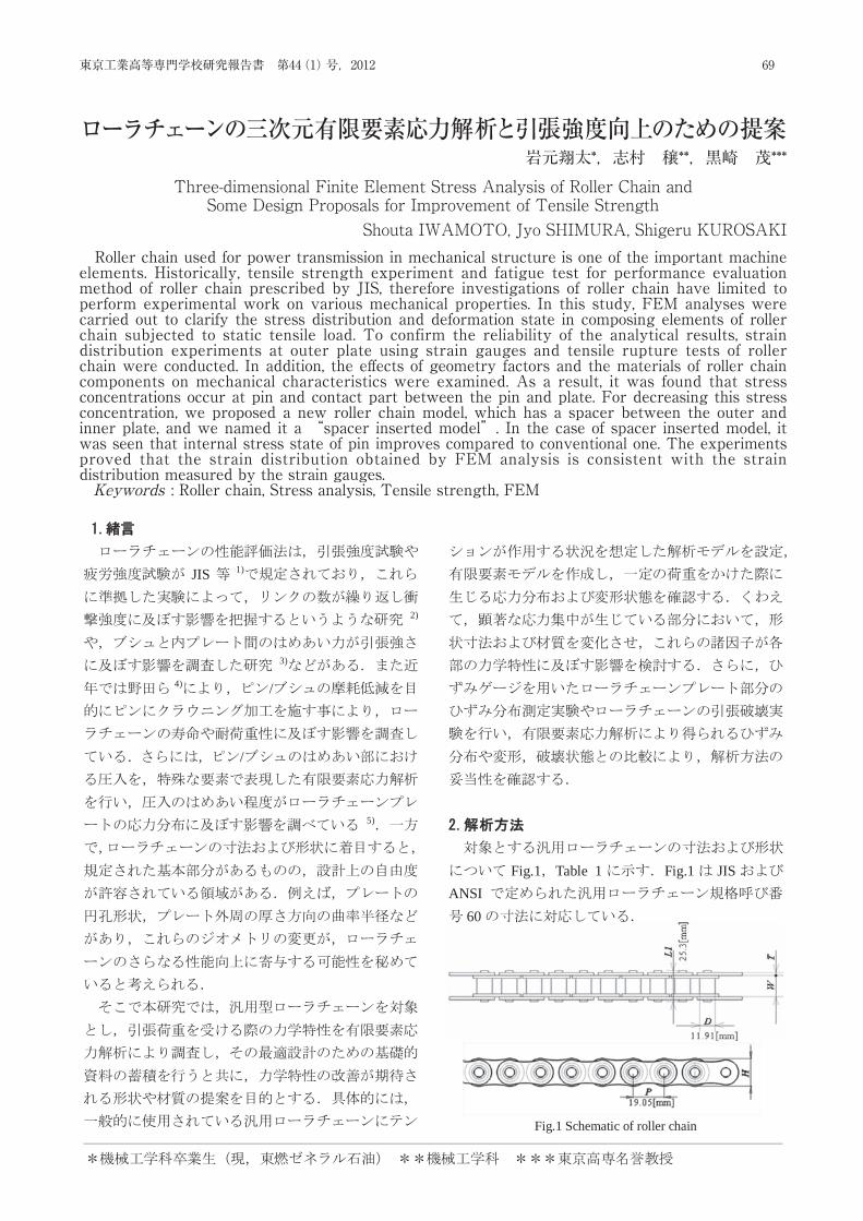
44(1) 2012
Three-dimensional Finite Element Stress Analysis of Roller Chain and Some Design Proposals for Improvement of Tensile Strength
Shouta IWAMOTO, Jyo SHIMURA, Shigeru KUROSAKI
Roller chain used for power transmission in mechanical structure is one of the important machine elements. Historically,
tensile strength experiment and fatigue test for performance evaluation method of roller chain prescribed by JIS, therefore investigations of roller chain have limited to perform experimental work on various mechanical properties. In this study, FEM analyses were carried out to clarify the stress distribution and deformation state in composing elements of roller chain subjected to static tensile load. To confirm the reliability of the analytical results, strain distribution experiments at outer plate using strain gauges and tensile rupture tests of roller chain were conducted. In addition, the effects of geometry factors and the materials of roller chain components on mechanical characteristics were examined. As a result, it was found that stress concentrations occur at pin and contact part between the pin and plate. For decreasing this stress concentration, we proposed a new roller chain model, which has a spacer between the outer and inner plate, and we named it a “spacer inserted model”. In the case of spacer inserted model, it was seen that internal stress state of pin improves compared to conventional one. The experiments proved that the strain distribution obtained by FEM analysis is consistent with the strain distribution measured by the strain gauges. (Keywords: Roller chain, Stress analysis, Tensile strength, FEM)
JIS 1)
2)
3)
4) /
/
5)
Fig.1 Table 1 Fig.1 JISANSI
60 Fig.1 Schematic of roller chain
69東京工業高等専門学校研究報告書 第44(1)号,2012
Roller chain used for power transmission in mechanical structure is one of the important machine elements. Historically, tensile strength experiment and fatigue test for performance evaluation method of roller chain prescribed by JIS, therefore investigations of roller chain have limited to perform experimental work on various mechanical properties. In this study, FEM analyses were carried out to clarify the stress distribution and deformation state in composing elements of roller chain subjected to static tensile load. To confirm the reliability of the analytical results, strain distribution experiments at outer plate using strain gauges and tensile rupture tests of roller chain were conducted. In addition, the eff ects of geometry factors and the materials of roller chain components on mechanical characteristics were examined. As a result, it was found that stress concentrations occur at pin and contact part between the pin and plate. For decreasing this stress concentration, we proposed a new roller chain model, which has a spacer between the outer and inner plate, and we named it a “spacer inserted model”. In the case of spacer inserted model, it was seen that internal stress state of pin improves compared to conventional one. The experiments proved that the strain distribution obtained by FEM analysis is consistent with the strain distribution measured by the strain gauges.Keywords : Roller chain, Stress analysis, Tensile strength, FEM
ローラチェーンの三次元有限要素応力解析と引張強度向上のための提案岩元翔太*,志村 穣**,黒崎 茂***
Three-dimensional Finite Element Stress Analysis of Roller Chain andSome Design Proposals for Improvement of Tensile Strength
Shouta IWAMOTO, Jyo SHIMURA, Shigeru KUROSAKI
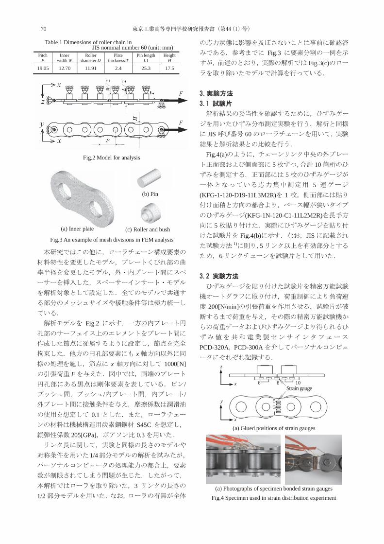
44(1)
6 8 10
5 3 1
x
y
z
x
Fig.2
xx 1000[N]
F/
/ /
0.1S45C
205[GPa] 0.3
1/4
31/2
Fig.3Fig.3(c)
JIS 60
Fig.4(a)5 10
55
(KFG-1-120-D19-11L3M2R) 1
(KFG-1N-120-C1-11L2M2R)5
Fig.4(b) JIS1) 5
6
200[N/min]
PCD-320A PCD-300A
Pitch P
Inner width W
Roller diameter D
Plate thickness T
Pin length L1
Height H
19.05 12.70 11.91 2.4 25.3 17.5
Table 1 Dimensions of roller chain in JIS nominal number 60 (unit: mm)
Fig.2 Model for analysis
Fig.3 An example of mesh divisions in FEM analysis
(a) Inner plate
(b) Pin
(c) Roller and bush
(a) Glued positions of strain gauges
(a) Photographs of specimen bonded strain gauges Fig.4 Specimen used in strain distribution experiment
Strain gauge
70 東京工業高等専門学校研究報告書(第44(1)号)
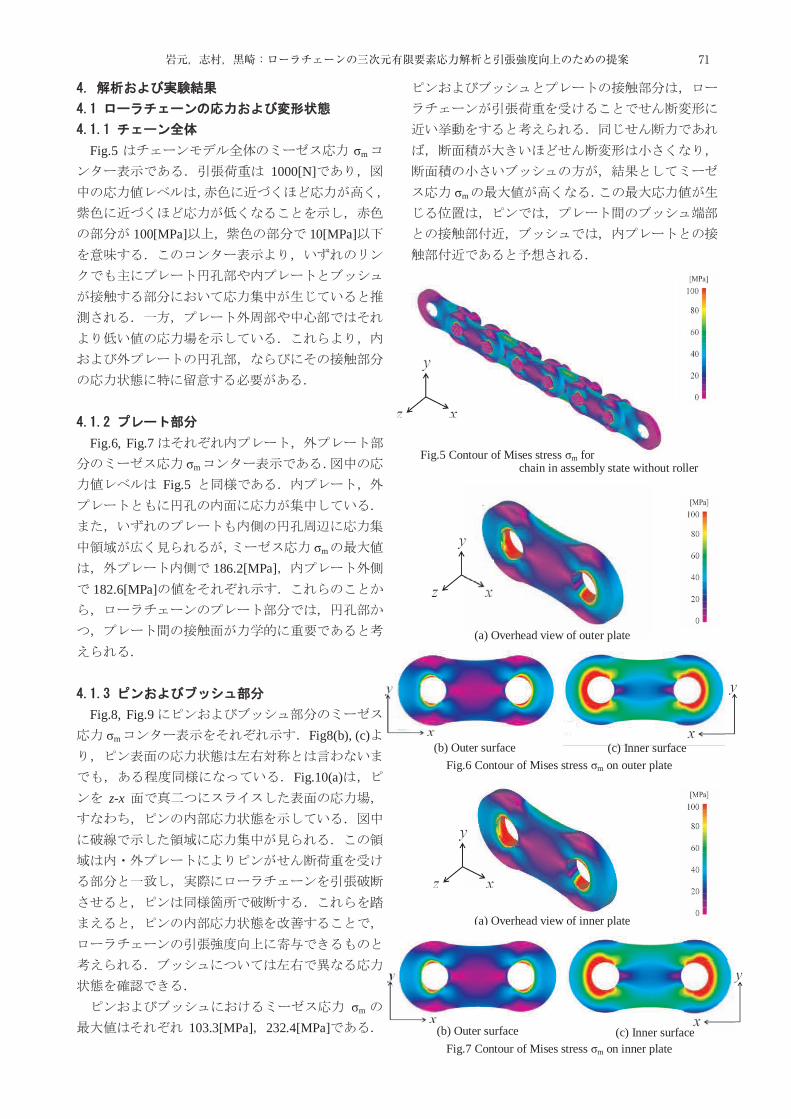
3
Fig.5 σm
1000[N]
100[MPa] 10[MPa]
Fig.6, Fig.7σm
Fig.5
σm
186.2[MPa]182.6[MPa]
Fig.8, Fig.9σm Fig8(b), (c)
Fig.10(a)z-x
σm
103.3[MPa] 232.4[MPa]
σm
Fig.5 Contour of Mises stress σm for chain in assembly state without roller
(a) Overhead view of outer plate
(b) Outer surface (c) Inner surface Fig.6 Contour of Mises stress σm on outer plate
(a) Overhead view of inner plate
Fig.7 Contour of Mises stress σm on inner plate (b) Outer surface (c) Inner surface
71岩元,志村,黒崎:ローラチェーンの三次元有限要素応力解析と引張強度向上のための提案
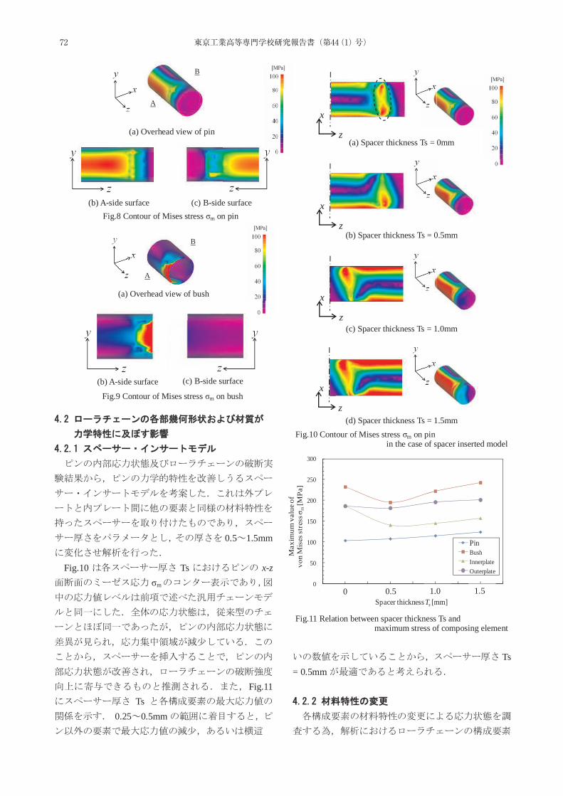
44(1)
0.5 1.5mm
Fig.10 Ts x-zσm
Fig.11Ts
0.25 0.5mm
Ts = 0.5mm
(a) Overhead view of pin
(c) B-side surface (b) A-side surface Fig.8 Contour of Mises stress σm on pin
(a) Overhead view of bush
(c) B-side surface (b) A-side surface
Fig.9 Contour of Mises stress σm on bush
x
z (a) Spacer thickness Ts = 0mm
x
z (b) Spacer thickness Ts = 0.5mm
x
z (c) Spacer thickness Ts = 1.0mm
x
z (d) Spacer thickness Ts = 1.5mm
Fig.10 Contour of Mises stress σm on pin in the case of spacer inserted model
0
50
100
150
200
250
300
0.5 1 1.5 2 2.5 3 3.5 4 4.5
Max
imum
val
ue o
fvo
n M
ises
stre
ss σ
m[M
Pa]
Spacer thickness Ts [mm]
PinBushInnerplateOuterplate
0 0.5 1.0 1.5
Fig.11 Relation between spacer thickness Ts and maximum stress of composing element
A
B
A
B
72 東京工業高等専門学校研究報告書(第44(1)号)
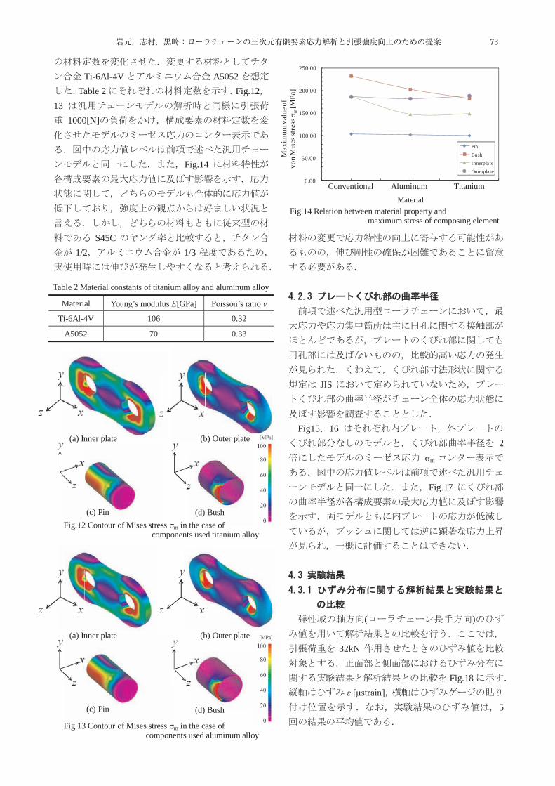
5
Ti-6Al-4V A5052Table 2 Fig.12
131000[N]
Fig.14
S45C1/2 1/3
JIS
Fig15 16
2σm
Fig.17
( )
32kN
Fig.18ε [μstrain]
5
Material Young’s modulus E[GPa] Poisson’s ratio ν
Ti-6Al-4V 106 0.32
A5052 70 0.33
Table 2 Material constants of titanium alloy and aluminum alloy
(a) Inner plate (b) Outer plate
(c) Pin (d) Bush
( )
Fig.12 Contour of Mises stress σm in the case of components used titanium alloy
(a) Inner plate (b) Outer plate
(c) Pin (d) Bush
( )
Fig.13 Contour of Mises stress σm in the case of components used aluminum alloy
0.00
50.00
100.00
150.00
200.00
250.00
0.5 1 1.5 2 2.5 3 3.5
Max
imum
val
ue o
fvo
n M
ises
stre
ss σ
m[M
Pa]
Material
PinBushInnerplateOuterplate
Conventional Aluminum Titanium
Fig.14 Relation between material property and maximum stress of composing element
73岩元,志村,黒崎:ローラチェーンの三次元有限要素応力解析と引張強度向上のための提案
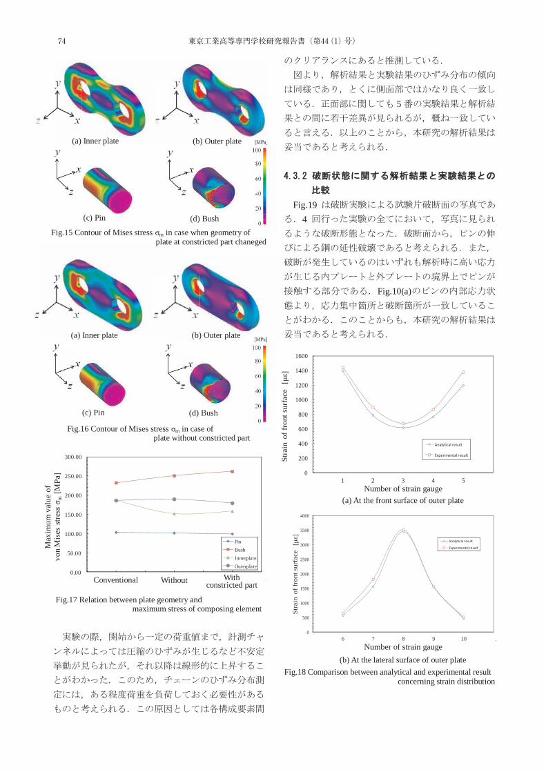
44(1)
5
Fig.19
4
Fig.10(a)
(b) Outer plate
(c) Pin (d) Bush
(a) Inner plate
Fig.15 Contour of Mises stress σm in case when geometry of plate at constricted part chaneged
(b) Outer plate
(c) Pin (d) Bush
(a) Inner plate
Fig.16 Contour of Mises stress σm in case of plate without constricted part
0.00
50.00
100.00
150.00
200.00
250.00
300.00
0.5 1 1.5 2 2.5 3 3.5
Max
imum
val
ue o
fvo
n M
ises
stre
ss σ
m[M
Pa]
Narrow volume
PinBushInnerplateOuterplate
Conventional Without With constricted part
Fig.17 Relation between plate geometry and maximum stress of composing element
0
200
400
600
800
1000
1200
1400
1600
0 1 2 3 4 5 6
Stra
in o
f fro
nt s
urfa
ce[με]
Number of strain gage
Analytical result
Experimental result
0
500
1000
1500
2000
2500
3000
3500
4000
5 6 7 8 9 10 11
Stra
in o
f fro
nt s
urfa
ce[με]
Number of strain gauge position
Analytical result
Experimental result
(a) At the front surface of outer plate
(b) At the lateral surface of outer plate
Number of strain gauge
Number of strain gauge
Fig.18 Comparison between analytical and experimental result concerning strain distribution
74 東京工業高等専門学校研究報告書(第44(1)号)
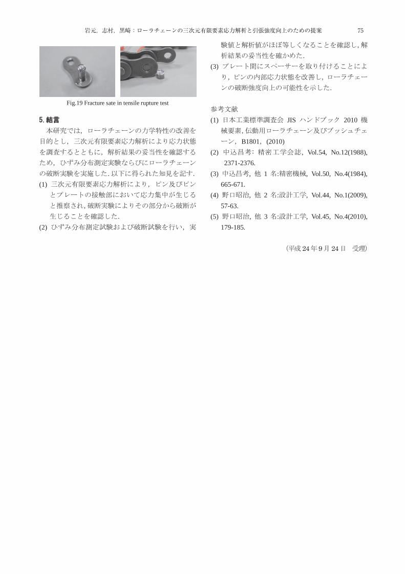
7
Strain gauge
(1)
(2)
(3)
(1) JIS 2010
B1801 (2010) (2) : , Vol.54, No.12(1988),
2371-2376. (3) , 1 : , Vol.50, No.4(1984),
665-671. (4) , 2 : , Vol.44, No.1(2009),
57-63. (5) , 3 : , Vol.45, No.4(2010),
179-185.
24 9 24
Fig.19 Fracture sate in tensile rupture test
24 9 24
75岩元,志村,黒崎:ローラチェーンの三次元有限要素応力解析と引張強度向上のための提案

76 東京工業高等専門学校研究報告書(第44(1)号)
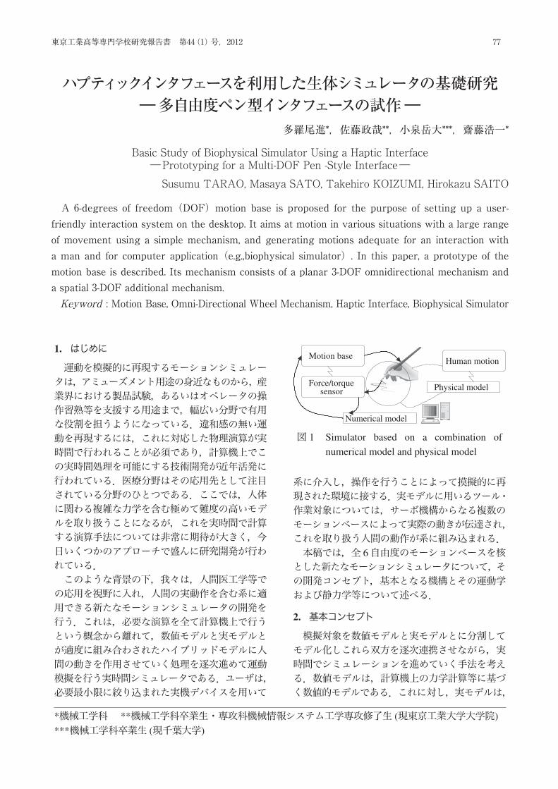
東京工業高等専門学校研究報告書 第 44(1)号,2012
ハプティックインタフェースを利用した生体シミュレータの基礎研究
—多自由度ペン型インタフェースの試作—多羅尾進 ∗,佐藤政哉 ∗∗,小泉岳大 ∗∗∗,齊藤浩一 ∗
Basic Study of Biophysical Simulator Using a Haptic Interface—Prototyping for a Multi-DOF Pen-Style Interface—
Susumu TARAO, Masaya SATO, Takehiro KOIZUMI and Hirokazu SAITO
A 6-degrees of freedom (DOF) motion base is proposed for the purpose of setting up a user-friendlyinteraction system on the desktop. It aims at motion in various situations with a large range of movement using asimple mechanism, and generating motions adequate for an interaction with a man and for computer application(e.g., biophysical simulator). In this paper, a prototype of the motion base is described. Its mechanism consistsof a combination of a planar 3-DOF omnidirectional mechanism and a spatial 3-DOF additional mechanism.(Key Word: Motion Base, Omni-Directional Wheel Mechanism, Haptic Interface, Biophysical Simulator)
1. はじめに
運動を模擬的に再現するモーションシミュレータは,アミューズメント用途の身近なものから,産業界における製品試験,あるいはオペレータの操作習熟等を支援する用途まで,幅広い分野で有用な役割を担うようになっている.違和感の無い運動を再現するには,これに対応した物理演算が実時間で行われることが必須であり,計算機上でこの実時間処理を可能にする技術開発が近年活発に行われている.医療分野はその応用先として注目されている分野のひとつである.ここでは,人体に関わる複雑な力学を含む極めて難度の高いモデルを取り扱うことになるが,これを実時間で計算する演算手法については非常に期待が大きく,今日いくつかのアプローチで盛んに研究開発が行われている.このような背景の下,我々は,人間医工学等での応用を視野に入れ,人間の実動作を含む系に適用できる新たなモーションシミュレータの開発を行う.これは,必要な演算を全て計算機上で行うという概念から離れて,数値モデルと実モデルとが適度に組み合わされたハイブリッドモデルに人間の動きを作用させていく処理を逐次進めて運動模擬を行う実時間シミュレータである.ユーザは,必要最小限に絞り込まれた実機デバイスを用いて
Motion base
Force/torquesensor
Human motion
Physical model
Numerical model
図 1 Simulator based on a combination ofnumerical model and physical model
系に介入し,操作を行うことによって摸擬的に再現された環境に接する.実モデルに用いるツール・作業対象については,サーボ機構からなる複数のモーションベースによって実際の動きが伝達され,これを取り扱う人間の動作が系に組み込まれる.本稿では,全 6自由度のモーションベースを核とした新たなモーションシミュレータについて,その開発コンセプト,基本となる機構とその運動学および静力学等について述べる.
2. 基本コンセプト
模擬対象を数値モデルと実モデルとに分割してモデル化しこれら双方を逐次連携させながら,実時間でシミュレーションを進めていく手法を考える.数値モデルは,計算機上の力学計算等に基づく数値的モデルである.これに対し,実モデルは,
*機械工学科 **機械工学科卒業生・専攻科機械情報システム工学専攻修了生 (現東京工業大学大学院)***機械工学科卒業生 (現千葉大学)
77東京工業高等専門学校研究報告書 第44(1)号,2012
A 6-degrees of freedom(DOF)motion base is proposed for the purpose of setting up a user-friendly interaction system on the desktop. It aims at motion in various situations with a large range of movement using a simple mechanism, and generating motions adequate for an interaction with a man and for computer application(e.g.,biophysical simulator). In this paper, a prototype of the motion base is described. Its mechanism consists of a planar 3-DOF omnidirectional mechanism and a spatial 3-DOF additional mechanism.Keyword : Motion Base, Omni-Directional Wheel Mechanism, Haptic Interface, Biophysical Simulator
ハプティックインタフェースを利用した生体シミュレータの基礎研究―多自由度ペン型インタフェースの試作―
多羅尾進*,佐藤政哉**,小泉岳大***,齋藤浩一*
Basic Study of Biophysical Simulator Using a Haptic Interface―Prototyping for a Multi-DOF Pen -Style Interface―Susumu TARAO, Masaya SATO, Takehiro KOIZUMI, Hirokazu SAITO
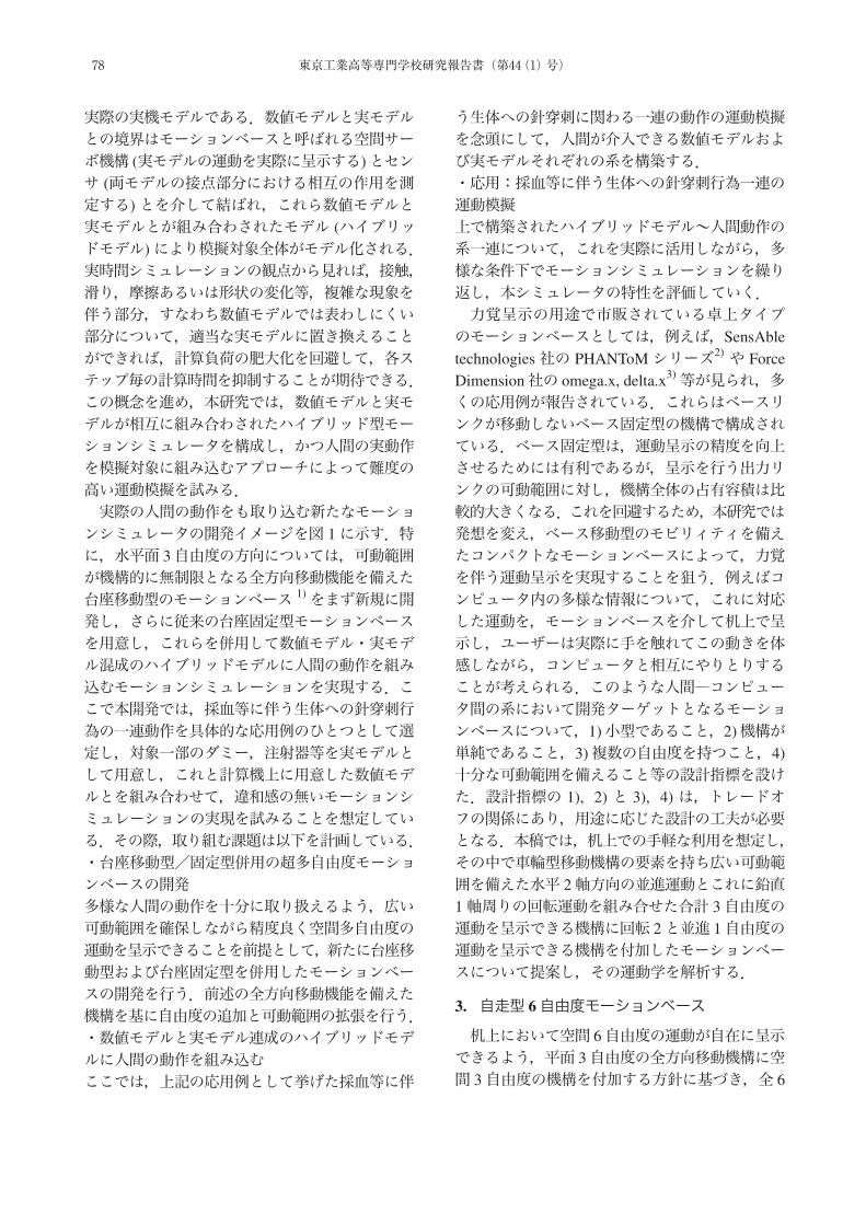
実際の実機モデルである.数値モデルと実モデルとの境界はモーションベースと呼ばれる空間サーボ機構 (実モデルの運動を実際に呈示する)とセンサ (両モデルの接点部分における相互の作用を測定する)とを介して結ばれ,これら数値モデルと実モデルとが組み合わされたモデル (ハイブリッドモデル)により模擬対象全体がモデル化される.実時間シミュレーションの観点から見れば,接触,滑り,摩擦あるいは形状の変化等,複雑な現象を伴う部分,すなわち数値モデルでは表わしにくい部分について,適当な実モデルに置き換えることができれば,計算負荷の肥大化を回避して,各ステップ毎の計算時間を抑制することが期待できる.この概念を進め,本研究では,数値モデルと実モデルが相互に組み合わされたハイブリッド型モーションシミュレータを構成し,かつ人間の実動作を模擬対象に組み込むアプローチによって難度の高い運動模擬を試みる.実際の人間の動作をも取り込む新たなモーションシミュレータの開発イメージを図 1に示す.特に,水平面 3自由度の方向については,可動範囲が機構的に無制限となる全方向移動機能を備えた台座移動型のモーションベース 1)をまず新規に開発し,さらに従来の台座固定型モーションベースを用意し,これらを併用して数値モデル・実モデル混成のハイブリッドモデルに人間の動作を組み込むモーションシミュレーションを実現する.ここで本開発では,採血等に伴う生体への針穿刺行為の一連動作を具体的な応用例のひとつとして選定し,対象一部のダミー,注射器等を実モデルとして用意し,これと計算機上に用意した数値モデルとを組み合わせて,違和感の無いモーションシミュレーションの実現を試みることを想定している.その際,取り組む課題は以下を計画している.・台座移動型/固定型併用の超多自由度モーションベースの開発多様な人間の動作を十分に取り扱えるよう,広い可動範囲を確保しながら精度良く空間多自由度の運動を呈示できることを前提として,新たに台座移動型および台座固定型を併用したモーションベースの開発を行う.前述の全方向移動機能を備えた機構を基に自由度の追加と可動範囲の拡張を行う.・数値モデルと実モデル連成のハイブリッドモデルに人間の動作を組み込むここでは,上記の応用例として挙げた採血等に伴
う生体への針穿刺に関わる一連の動作の運動模擬を念頭にして,人間が介入できる数値モデルおよび実モデルそれぞれの系を構築する.・応用:採血等に伴う生体への針穿刺行為一連の運動模擬上で構築されたハイブリッドモデル~人間動作の系一連について,これを実際に活用しながら,多様な条件下でモーションシミュレーションを繰り返し,本シミュレータの特性を評価していく.力覚呈示の用途で市販されている卓上タイプのモーションベースとしては,例えば,SensAbletechnologies社の PHANToMシリーズ2) や ForceDimension社の omega.x, delta.x3)等が見られ,多くの応用例が報告されている.これらはベースリンクが移動しないベース固定型の機構で構成されている.ベース固定型は,運動呈示の精度を向上させるためには有利であるが,呈示を行う出力リンクの可動範囲に対し,機構全体の占有容積は比較的大きくなる.これを回避するため,本研究では発想を変え,ベース移動型のモビリィティを備えたコンパクトなモーションベースによって,力覚を伴う運動呈示を実現することを狙う.例えばコンピュータ内の多様な情報について,これに対応した運動を,モーションベースを介して机上で呈示し,ユーザーは実際に手を触れてこの動きを体感しながら,コンピュータと相互にやりとりすることが考えられる.このような人間―コンピュータ間の系において開発ターゲットとなるモーションベースについて,1)小型であること,2)機構が単純であること,3)複数の自由度を持つこと,4)十分な可動範囲を備えること等の設計指標を設けた.設計指標の 1), 2) と 3), 4) は,トレードオフの関係にあり,用途に応じた設計の工夫が必要となる.本稿では,机上での手軽な利用を想定し,その中で車輪型移動機構の要素を持ち広い可動範囲を備えた水平 2軸方向の並進運動とこれに鉛直1軸周りの回転運動を組み合せた合計 3自由度の運動を呈示できる機構に回転 2と並進 1自由度の運動を呈示できる機構を付加したモーションベースについて提案し,その運動学を解析する.
3. 自走型 6自由度モーションベース
机上において空間 6自由度の運動が自在に呈示できるよう,平面 3自由度の全方向移動機構に空間 3自由度の機構を付加する方針に基づき,全 6
78 東京工業高等専門学校研究報告書(第44(1)号)
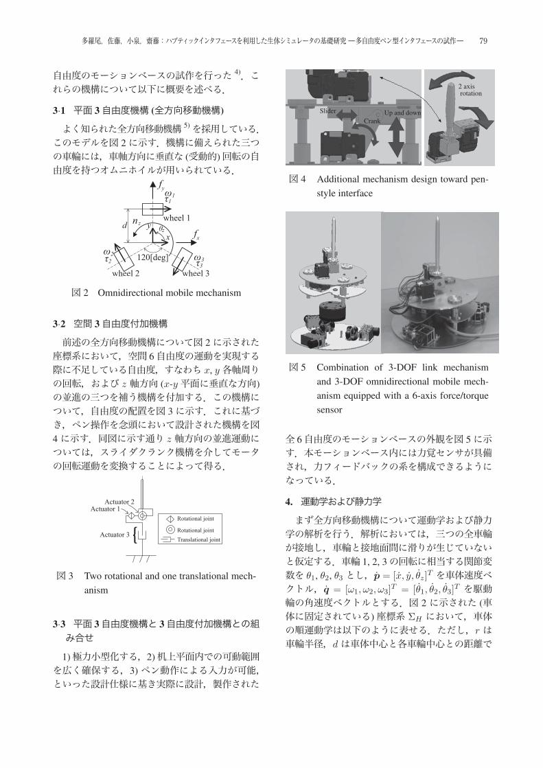
自由度のモーションベースの試作を行った 4).これらの機構について以下に概要を述べる.
3·1 平面 3自由度機構 (全方向移動機構)
よく知られた全方向移動機構 5)を採用している.このモデルを図 2に示す.機構に備えられた三つの車輪には,車軸方向に垂直な (受動的)回転の自由度を持つオムニホイルが用いられている.
図 2 Omnidirectional mobile mechanism
3·2 空間 3自由度付加機構
前述の全方向移動機構について図 2に示された座標系において,空間 6自由度の運動を実現する際に不足している自由度,すなわち x, y各軸周りの回転,および z 軸方向 (x-y平面に垂直な方向)の並進の三つを補う機構を付加する.この機構について,自由度の配置を図 3に示す.これに基づき,ペン操作を念頭において設計された機構を図4に示す.同図に示す通り z 軸方向の並進運動については,スライダクランク機構を介してモータの回転運動を変換することによって得る.
図 3 Two rotational and one translational mech-anism
3·3 平面 3自由度機構と 3自由度付加機構との組み合せ
1)極力小型化する,2)机上平面内での可動範囲を広く確保する,3)ペン動作による入力が可能,といった設計仕様に基き実際に設計,製作された
Crank
Slider Up and down
2 axisrotation
図 4 Additional mechanism design toward pen-style interface
図 5 Combination of 3-DOF link mechanismand 3-DOF omnidirectional mobile mech-anism equipped with a 6-axis force/torquesensor
全 6自由度のモーションベースの外観を図 5に示す.本モーションベース内には力覚センサが具備され,力フィードバックの系を構成できるようになっている.
4. 運動学および静力学
まず全方向移動機構について運動学および静力学の解析を行う.解析においては,三つの全車輪が接地し,車輪と接地面間に滑りが生じていないと仮定する.車輪 1, 2, 3の回転に相当する関節変数を θ1, θ2, θ3 とし,p = [x, y, θz]
T を車体速度ベクトル,q = [ω1, ω2, ω3]
T = [θ1, θ2, θ3]T を駆動
輪の角速度ベクトルとする.図 2 に示された (車体に固定されている)座標系 ΣH において,車体の順運動学は以下のように表せる.ただし,r は車輪半径,dは車体中心と各車輪中心との距離で
79多羅尾,佐藤,小泉,齋藤:ハプティックインタフェースを利用した生体シミュレータの基礎研究 ―多自由度ペン型インタフェースの試作―
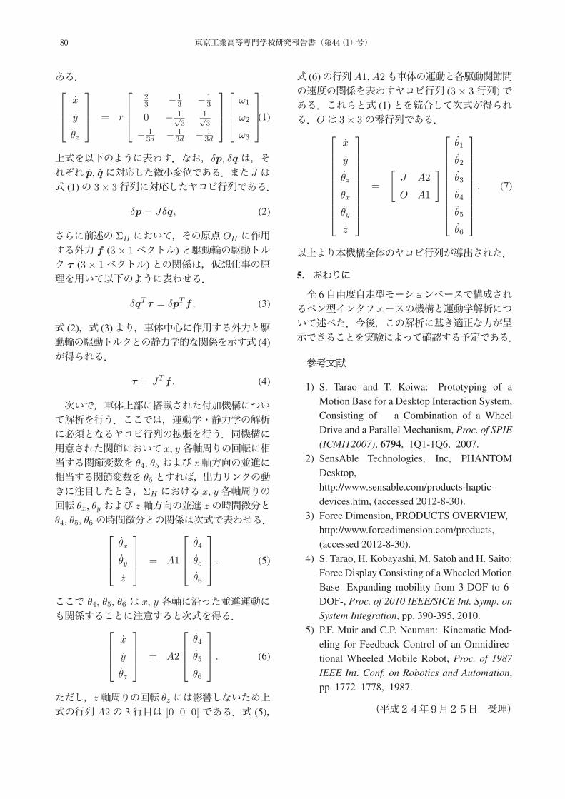
ある.⎡⎢⎢⎣
x
y
θz
⎤⎥⎥⎦ = r
⎡⎢⎢⎣
23 −1
3 −13
0 − 1√3
1√3
− 13d − 1
3d − 13d
⎤⎥⎥⎦⎡⎢⎢⎣
ω1
ω2
ω3
⎤⎥⎥⎦ .(1)
上式を以下のように表わす.なお,δp, δqは,それぞれ p, qに対応した微小変位である.また J は式 (1)の 3× 3行列に対応したヤコビ行列である.
δp = Jδq, (2)
さらに前述の ΣH において,その原点 OH に作用する外力 f (3× 1ベクトル)と駆動輪の駆動トルク τ (3× 1ベクトル)との関係は,仮想仕事の原理を用いて以下のように表わせる.
δqTτ = δpTf , (3)
式 (2),式 (3)より,車体中心に作用する外力と駆動輪の駆動トルクとの静力学的な関係を示す式 (4)が得られる.
τ = JTf . (4)
次いで,車体上部に搭載された付加機構について解析を行う.ここでは,運動学・静力学の解析に必須となるヤコビ行列の拡張を行う.同機構に用意された関節において x, y各軸周りの回転に相当する関節変数を θ4, θ5 および z 軸方向の並進に相当する関節変数を θ6とすれば,出力リンクの動きに注目したとき,ΣH における x, y各軸周りの回転 θx, θy および z軸方向の並進 zの時間微分とθ4, θ5, θ6 の時間微分との関係は次式で表わせる.⎡
⎢⎢⎣θx
θy
z
⎤⎥⎥⎦ = A1
⎡⎢⎢⎣
θ4
θ5
θ6
⎤⎥⎥⎦ . (5)
ここで θ4, θ5, θ6 は x, y 各軸に沿った並進運動にも関係することに注意すると次式を得る.⎡
⎢⎢⎣x
y
θz
⎤⎥⎥⎦ = A2
⎡⎢⎢⎣
θ4
θ5
θ6
⎤⎥⎥⎦ . (6)
ただし,z軸周りの回転 θz には影響しないため上式の行列 A2の 3行目は [0 0 0] である.式 (5),
式 (6)の行列A1, A2も車体の運動と各駆動関節間の速度の関係を表わすヤコビ行列 (3 × 3行列)である.これらと式 (1)とを統合して次式が得られる.Oは 3× 3の零行列である.⎡
⎢⎢⎢⎢⎢⎢⎢⎢⎢⎢⎣
x
y
θz
θx
θy
z
⎤⎥⎥⎥⎥⎥⎥⎥⎥⎥⎥⎦
=
[J A2
O A1
]⎡⎢⎢⎢⎢⎢⎢⎢⎢⎢⎢⎣
θ1
θ2
θ3
θ4
θ5
θ6
⎤⎥⎥⎥⎥⎥⎥⎥⎥⎥⎥⎦. (7)
以上より本機構全体のヤコビ行列が導出された.
5. おわりに
全 6自由度自走型モーションベースで構成されるペン型インタフェースの機構と運動学解析について述べた.今後,この解析に基き適正な力が呈示できることを実験によって確認する予定である.
参考文献
1) S. Tarao and T. Koiwa: Prototyping of aMotion Base for a Desktop Interaction System,Consisting of a Combination of a WheelDrive and a Parallel Mechanism, Proc. of SPIE(ICMIT2007), 6794, 1Q1-1Q6, 2007.
2) SensAble Technologies, Inc, PHANTOMDesktop,http://www.sensable.com/products-haptic-devices.htm, (accessed 2012-8-30).
3) Force Dimension, PRODUCTS OVERVIEW,http://www.forcedimension.com/products,(accessed 2012-8-30).
4) S. Tarao, H. Kobayashi, M. Satoh and H. Saito:Force Display Consisting of a Wheeled MotionBase -Expanding mobility from 3-DOF to 6-DOF-, Proc. of 2010 IEEE/SICE Int. Symp. onSystem Integration, pp. 390-395, 2010.
5) P.F. Muir and C.P. Neuman: Kinematic Mod-eling for Feedback Control of an Omnidirec-tional Wheeled Mobile Robot, Proc. of 1987IEEE Int. Conf. on Robotics and Automation,pp. 1772–1778, 1987.
(平成24年9月25日 受理)
80 東京工業高等専門学校研究報告書(第44(1)号)
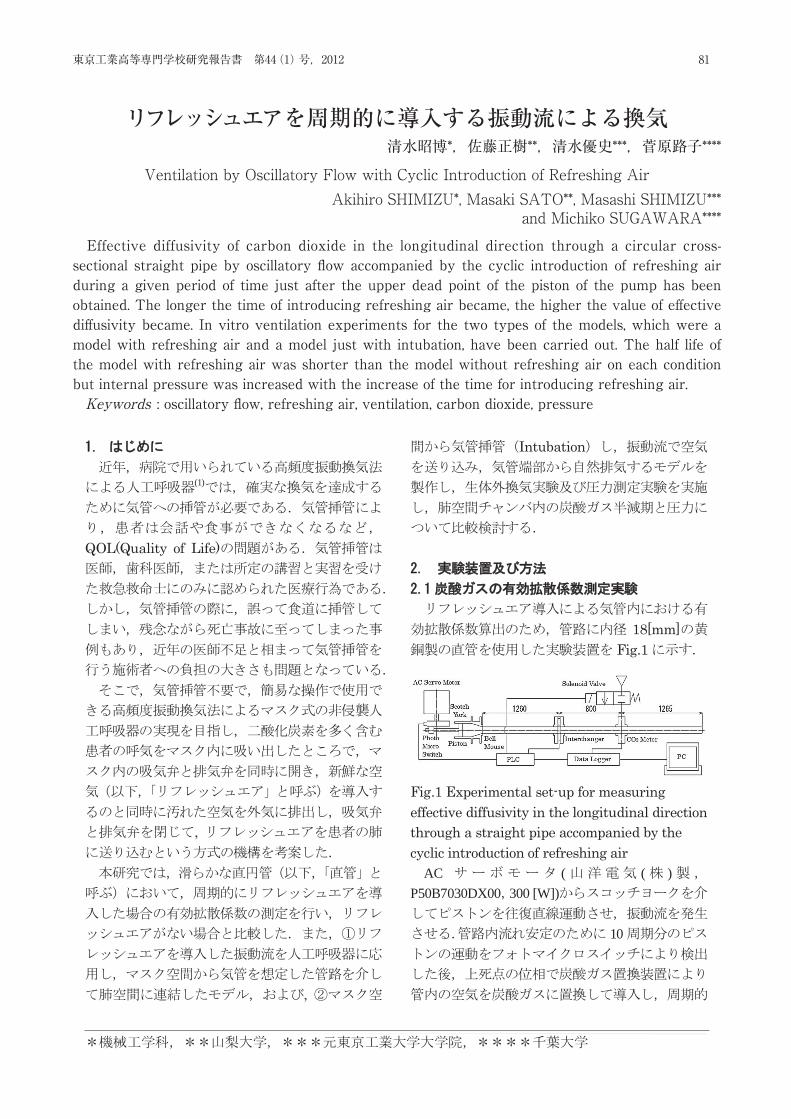
44 2012
Akihiro SHIMIZU , Masaki SATO , Masashi SHIMIZU , and Michiko SUGAWARA
Effective diffusivity in the longitudinal direction through a circular cross-sectional straight pipe by oscillatory flow accompanied by the cyclic introduction of refreshing air within a given period of time just after the upper dead point of the piston of the pump has been obtained. The longer the time of introducing refreshing air became, the higher the value of effective diffusivity became. In vitro ventilation experiments for the two types of the models, which were a model with refreshing air and a model just with intubation, have been carried out. The half life of the model with refreshing air was shorter than the model without refreshing air on each condition but internal pressure was increased with the increase of the time for introducing refreshing air.
(Keywords: oscillatory flow, refreshing air, ventilation)
(1)
QOL(Quality of Life)
,
,
Intubation
18[mm]Fig.1
Fig.1 Experimental set-up for measuring effective diffusivity in the longitudinal direction through a straight pipe accompanied by the cyclic introduction of refreshing air
AC ( ( )P50B7030DX00 300 [W])
10
81東京工業高等専門学校研究報告書 第44(1)号,2012
Effective diffusivity of carbon dioxide in the longitudinal direction through a circular cross-sectional straight pipe by oscillatory fl ow accompanied by the cyclic introduction of refreshing air during a given period of time just after the upper dead point of the piston of the pump has been obtained. The longer the time of introducing refreshing air became, the higher the value of eff ective diff usivity became. In vitro ventilation experiments for the two types of the models, which were a model with refreshing air and a model just with intubation, have been carried out. The half life of the model with refreshing air was shorter than the model without refreshing air on each condition but internal pressure was increased with the increase of the time for introducing refreshing air. Keywords : oscillatory fl ow, refreshing air, ventilation, carbon dioxide, pressure
リフレッシュエアを周期的に導入する振動流による換気清水昭博*,佐藤正樹**,清水優史***,菅原路子****
Ventilation by Oscillatory Flow with Cyclic Introduction of Refreshing AirAkihiro SHIMIZU*, Masaki SATO**, Masashi SHIMIZU***
and Michiko SUGAWARA****
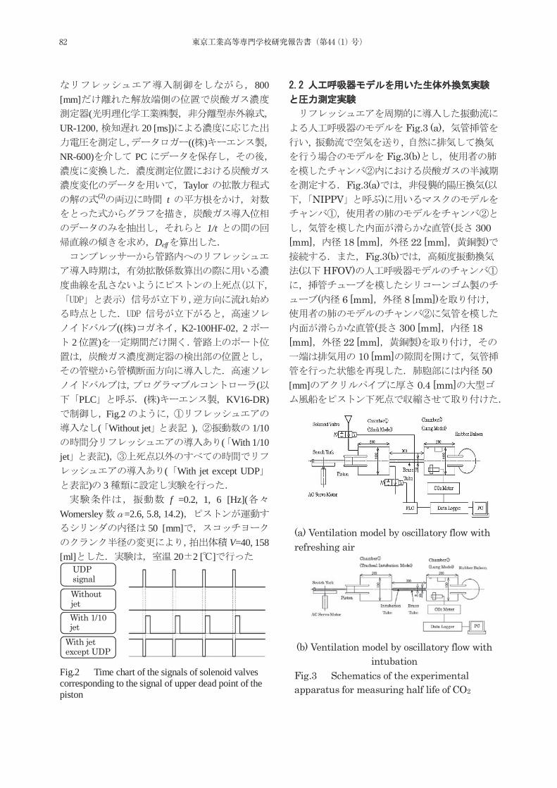
44
800 [mm]
(UR-1200 20 [ms])
(( )NR-600) PC
Taylor(2) t
1/tDeff
(( ) K2-100HF-02 22 )
(PLC ( ) KV16-DR)
Fig.2( Without jet ) 1/10
( With 1/10 jet )
( With jet except UDP) 3
f =0.2, 1, 6 [Hz](Womersley =2.6, 5.8, 14.2)
50 [mm]V=40, 158
[ml] 20 2 [ ]
Fig.2 Time chart of the signals of solenoid valves corresponding to the signal of upper dead point of the piston
Fig.3 (a), ,
Fig.3(b)
Fig.3(a) (NIPPV )
( 300 [mm] 18 [mm] 22 [mm] )
Fig.3(b)( HFOV)
( 6 [mm] 8 [mm])
( 300 [mm] 18 [mm] 22 [mm] )
10 [mm]50
[mm] 0.4 [mm]
(a) Ventilation model by oscillatory flow with refreshing air
(b) Ventilation model by oscillatory flow with
intubation Fig.3 Schematics of the experimental apparatus for measuring half life of CO2
Without jet With 1/10 jet
With jet except UDP
UDP signal
82 東京工業高等専門学校研究報告書(第44(1)号)
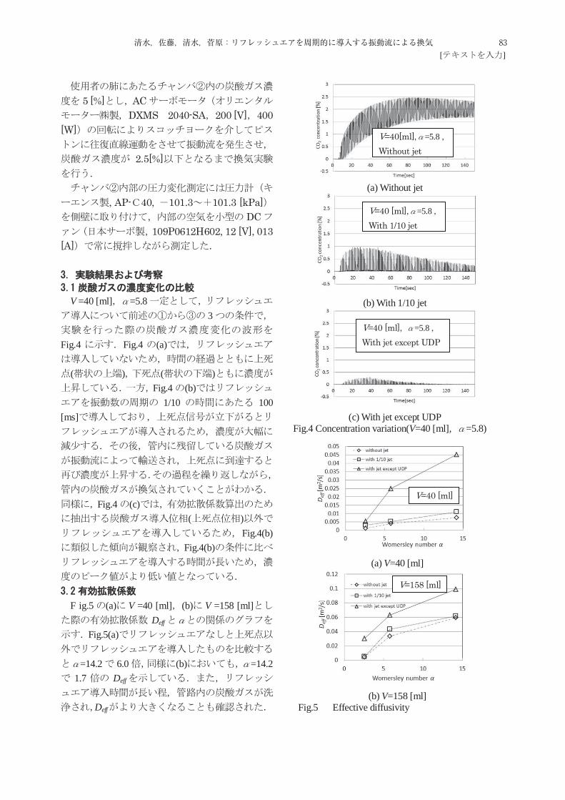
[ ]
5 [%] ACDXMS 2040-SA 200 [V] 400
[W]
2.5[%]
, AP- 40, 101.3 101.3 [kPa]
DC109P0612H602, 12 [V], 013
[A]
V =40 [ml] =5.83
Fig.4 Fig.4 (a)
( ) ( )Fig.4 (b)
1/10 100 [ms]
Fig.4 (c)( )
Fig.4(b)Fig.4(b)
F ig.5 (a) V =40 [ml] (b) V =158 [ml]Deff
Fig.5(a)
=14.2 6.0 (b) =14.21.7 Deff
Deff
(a) Without jet
(b) With 1/10 jet
(c) With jet except UDP Fig.4 Concentration variation(V=40 [ml], =5.8)
(a) V=40 [ml]
(b) V=158 [ml]
Fig.5 Effective diffusivity
V=40 [ml]
V=158 [ml]
V=40[ml], =5.8 , Without jet
V=40 [ml], =5.8 , With 1/10 jet
V=40 [ml], =5.8 , With jet except UDP
83清水,佐藤,清水,菅原:リフレッシュエアを周期的に導入する振動流による換気
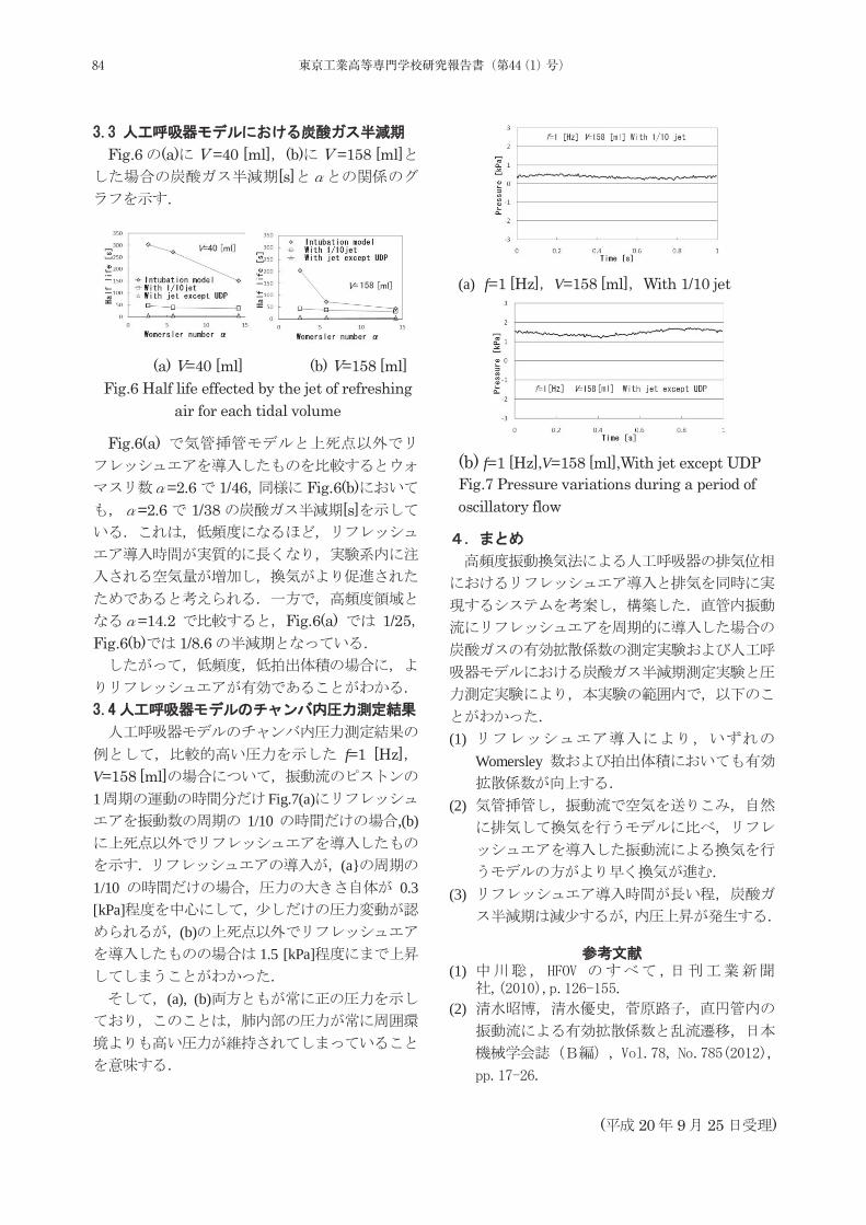
44
Fig.6 (a) V =40 [ml] (b) V =158 [ml][s]
Fig.6(a)
=2.6 1/46 Fig.6(b)=2.6 1/38 [s]
=14.2 Fig.6(a) 1/25Fig.6(b) 1/8.6
f=1 [Hz]V=158 [ml]1 Fig.7(a)
1/10 ,(b)
(a}1/10 0.3 [kPa]
(b)1.5 [kPa]
(a), (b)
(1)
Womersley
(2)
. (3)
(1)
(2)
(a) V=40 [ml] (b) V=158 [ml]
Fig.6 Half life effected by the jet of refreshing air for each tidal volume
( 20 9 25 )
(a) f=1 [Hz] V=158 [ml] With 1/10 jet
(b) f=1 [Hz],V=158 [ml],With jet except UDP Fig.7 Pressure variations during a period of oscillatory flow
( 20 9 25 )
84 東京工業高等専門学校研究報告書(第44(1)号)
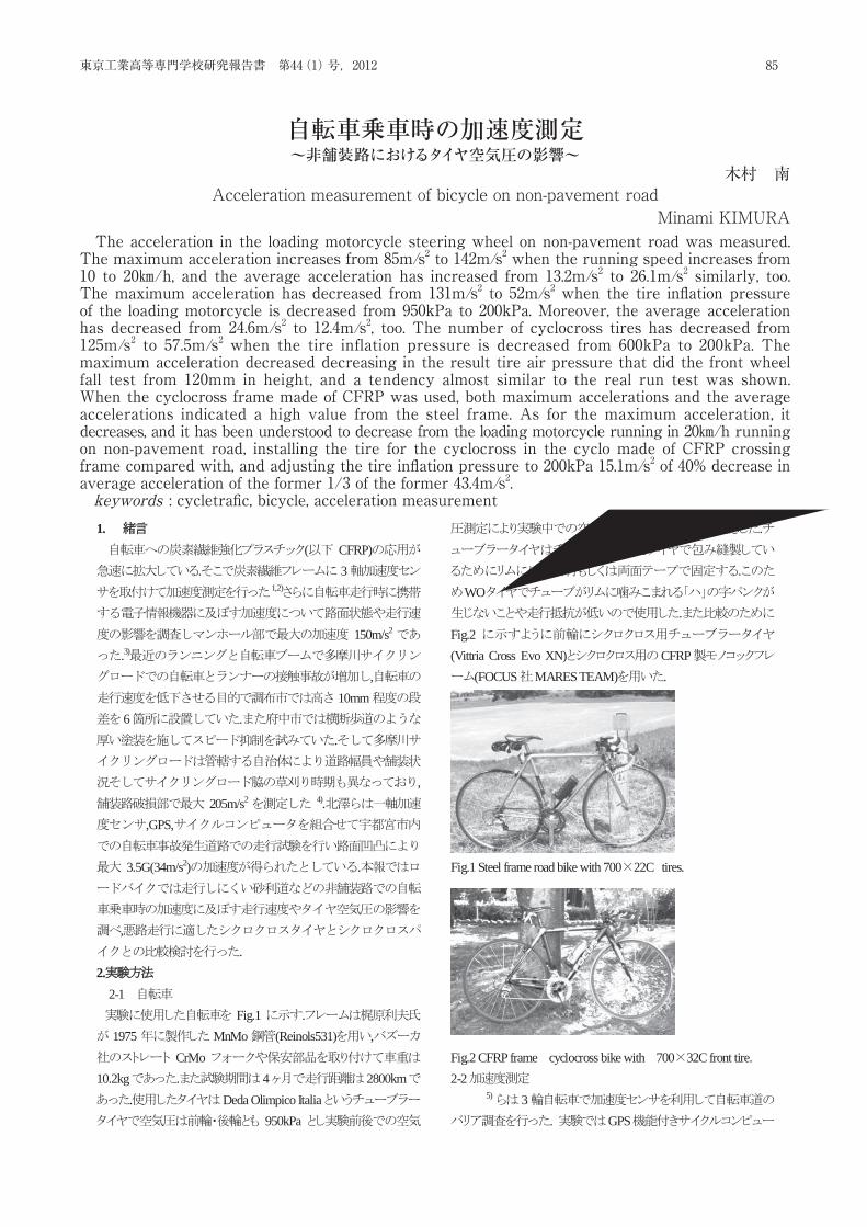
Acceleration measurement of bicycle on non-pavement road Minami KIMURA
The acceleration in the loading motorcycle steering wheel on non-pavement road was measured. The maximum acceleration increases from
85m/s2 to 142 m/s2 when the running speed increases from 10 to 20 km/h, and the average acceleration has increased from 13.2 m/s2 to 26.1 m/s2 similarly, too. The maximum acceleration has decreased from 131 m/s2 to 52 m/s2 when the tire inflation pressure of the loading motorcycle is decreased from 950kPa to 200kPa. Moreover, the average acceleration has decreased from 24.6 m/s2 to 12.4 m/s2, too. The number of cyclocross tires has decreased from 125 m/s2 to 57.5 m/s2 when the tire inflation pressure is decreased from 600kPa to 200kPa. The maximum acceleration decreased decreasing in the result tire air pressure that did the front wheel fall test from 120mm in height, and a tendency almost similar to the real run test was shown. When the cyclocross frame made of CFRP was used, both maximum accelerations and the average accelerations indicated a high value from the steel frame. As for the maximum acceleration, it decreases, and it has been understood to decrease from the loading motorcycle running in 20 km/h running on non-pavement road, installing the tire for the cyclocross in the cyclo made of CFRP crossing frame compared with, and adjusting the tire inflation pressure to 200kPa 15.1 m/s2 of 40% decrease in average acceleration of the former 1/3 of the former 43.4 m/s2. key words; cycletrafic, bicycle, acceleration measurement,
1. ( CFRP)
. 31,2)
150m/s2
.3)
,10mm
6 ..
,205m/s2 4).
,GPS,
3.5G(34m/s2) .
,.
2. 2-1
Fig.1 .1975 MnMo (Reinols531) ,
CrMo10.2kg . 4 2800km
. Deda Olimpico Italia950kPa
.
.WO
.Fig.2(Vittria Cross Evo XN) CFRP
(FOCUS MARES TEAM) .
Fig.1 Steel frame road bike with 700 22C tires.
Fig.2 CFRP frame cyclocross bike with 700 32C front tire. 2-2
5) 3. GPS
85東京工業高等専門学校研究報告書 第44(1)号,2012
The acceleration in the loading motorcycle steering wheel on non-pavement road was measured. The maximum acceleration increases from 85m/s2 to 142m/s2 when the running speed increases from 10 to 20㎞/h, and the average acceleration has increased from 13.2m/s2 to 26.1m/s2 similarly, too. The maximum acceleration has decreased from 131m/s2 to 52m/s2 when the tire infl ation pressure of the loading motorcycle is decreased from 950kPa to 200kPa. Moreover, the average acceleration has decreased from 24.6m/s2 to 12.4m/s2, too. The number of cyclocross tires has decreased from 125m/s2 to 57.5m/s2 when the tire inflation pressure is decreased from 600kPa to 200kPa. The maximum acceleration decreased decreasing in the result tire air pressure that did the front wheel fall test from 120mm in height, and a tendency almost similar to the real run test was shown. When the cyclocross frame made of CFRP was used, both maximum accelerations and the average accelerations indicated a high value from the steel frame. As for the maximum acceleration, it decreases, and it has been understood to decrease from the loading motorcycle running in 20㎞/h running on non-pavement road, installing the tire for the cyclocross in the cyclo made of CFRP crossing frame compared with, and adjusting the tire infl ation pressure to 200kPa 15.1m/s2 of 40% decrease in average acceleration of the former 1/3 of the former 43.4m/s2.keywords : cycletrafi c, bicycle, acceleration measurement
自転車乗車時の加速度測定~非舗装路におけるタイヤ空気圧の影響~
木村 南Acceleration measurement of bicycle on non-pavement road
Minami KIMURA
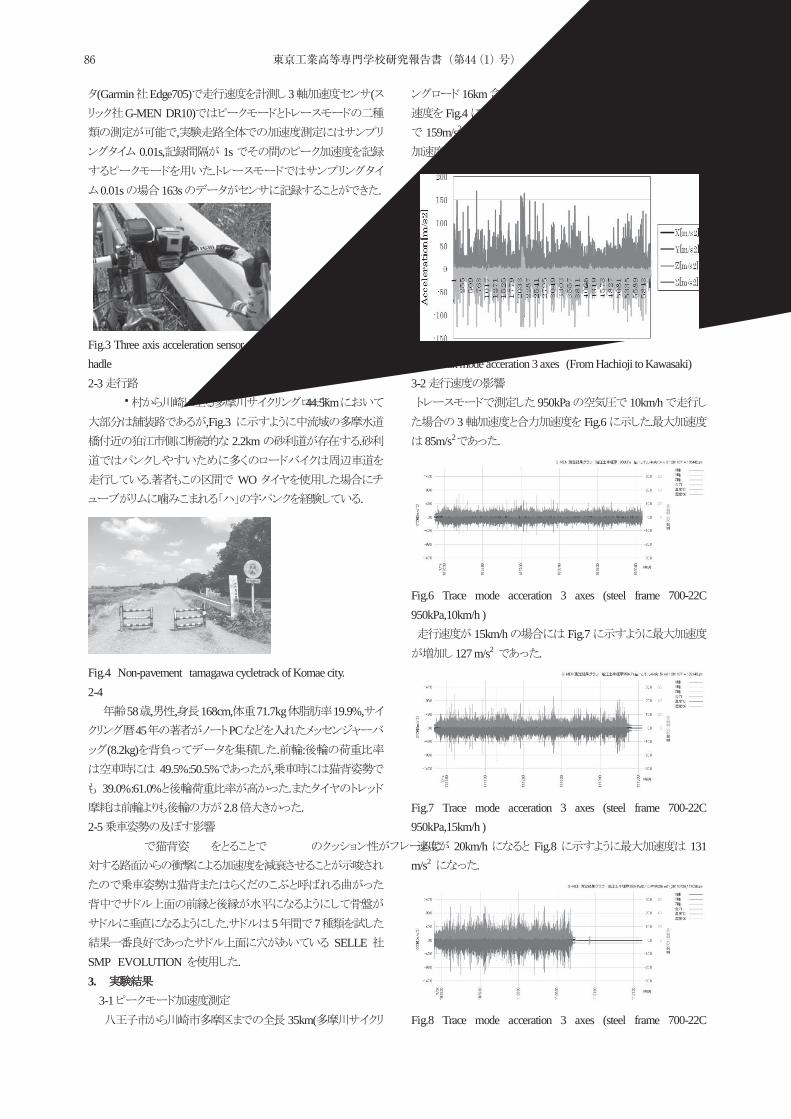
(Garmin Edge705) 3 (G-MEN DR10)
,0.01s, 1s
.0.01s 163s .
Fig.3 Three axis acceleration sensor and cycle-computer installed in hadle 2-3
44.5km,Fig.3
2.2km .
. WO.
Fig.4 Non-pavement tamagawa cycletrack of Komae city. 2-4
58 , , 168cm, 71.7kg 19.9%,45 PC
(8.2kg) . :49.5%:50.5% ,
39.0%:61.0% .2.8 .
2-5
. 5 7SELLE
SMP EVOLUTION . 3.
3-1 35km(
16km )Fig.4 .
159m/s2 ,Fig.5 150m/s27 .
Fig.5 Peak mode acceration 3 axes (From Hachioji to Kawasaki) 3-2 950kPa 10km/h
3 Fig.6 .85m/s2 .
Fig.6 Trace mode acceration 3 axes (steel frame 700-22C 950kPa,10km/h ) 15km/h Fig.7
127 m/s2 .
Fig.7 Trace mode acceration 3 axes (steel frame 700-22C 950kPa,15km/h ) 20km/h Fig.8 131 m/s2 .
Fig.8 Trace mode acceration 3 axes (steel frame 700-22C
86 東京工業高等専門学校研究報告書(第44(1)号)
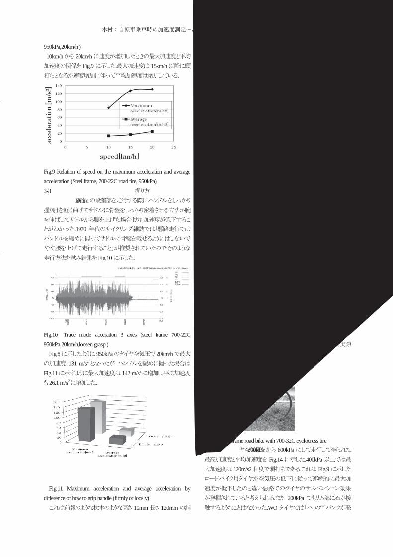
950kPa,20km/h ) 10km/h 20km/h
Fig.9 . 15km/h.
Fig.9 Relation of speed on the maximum acceleration and average acceleration (Steel frame, 700-22C road tire, 950kPa) 3-3
10mm
.1970
Fig.10 .
Fig.10 Trace mode acceration 3 axes (steel frame 700-22C 950kPa,20km/h,loosen grasp )
Fig.8 950kPa 20km/h131 m/s2
Fig.11 142 m/s2 ,26.1 m/s2 .
Fig.11 Maximum acceleration and average acceleration by
difference of how to grip handle (firmly or loosly) 10mm 120mm
mm mm
..
3-4 700C-22C
20km/h 200kPa950kPa
Fig.12 .700-22C.
.
Fig.12 Relation of air pressure on the maximum acceleration and average acceleration (Steel frame, 700-22C road tire, 20km/h) 3-5
Fig.13. 32mm
22mm ,220%
.
.
Fig.13 Steel frame road bike with 700-32C cyclocross tire 200kPa 600kPa
Fig.14 .400kPa120m/s2 . Fig.9
. 200kPa.WO
87木村:自転車乗車時の加速度測定~非舗装路におけるタイヤ空気圧の影響~
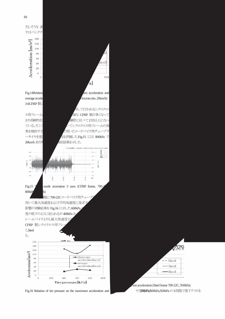
200kPa.
Fig.14Relation of tire pressure on the maximum acceleration and average acceleration (Steel frame, 700-32C cyclocross tire, 20km/h) 3-6CFRP
CFRP2
...
.Fig.15 800kPa20km/h .
Fig.15 Trace mode acceration 3 axes (CFRP frame, 700-22C, 800kPa,20km/h)
3-4 700-22C
Fig.16 .600kPa400kPa 800kPa Steel
,CFRP
,Steel.
Fig.16 Relation of tire pressure on the maximum acceleration and
average acceleration (CFRP frame, 700-22C, 20km/h) 3-7 CFRP
Fig.17. 400kPa 600kPa
115 m/s2 .Fig.12
.400kPa
.
Fig.17 Relation of tire pressure on the maximum acceleration and average acceleration (CFRP frame 700-32C cyclocross tire 20km/h) 4. 4-1 4-1-1
mm120 150 m/s2
.Fig.12,
. 120mm
( :10ms). 5 ,
.Fig.18 Steel700-22C X ,Y ,Z
Fig.18 Drop test acceleration (Steel frame 700-22C, 950kPa)
200kPa,600kPa,950kPa 3
88 東京工業高等専門学校研究報告書(第44(1)号)
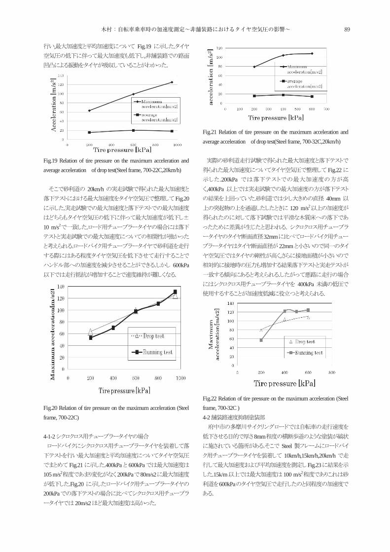
, Fig.19 .,
.
Fig.19 Relation of tire pressure on the maximum acceleration and average acceleration of drop test(Steel frame, 700-22C,20km/h)
20km/hFig.20
.
10 m/s2 .
.
. 600kPa.
Fig.20 Relation of tire pressure on the maximum acceleration (Steel frame, 700-22C) 4-1-2
Fig.21 .400kPa 600kPa105 m/s2 200kPa 80m/s2
.Fig.20200kPa
20m/s2 .
Fig.21 Relation of tire pressure on the maximum acceleration and average acceleration of drop test(Steel frame, 700-32C,20km/h)
Fig.22.200kPa
,400kPa. 40mm
120 m/s2
. 32mm
22mm,
.400kPa
.
Fig.22 Relation of tire pressure on the maximum acceleration (Steel frame, 700-32C ) 4-2
8mm. Steel
10km/h,15km/h,20km/hFig.23
.15k/m 100 m/s2
600kPa.
89木村:自転車乗車時の加速度測定~非舗装路におけるタイヤ空気圧の影響~
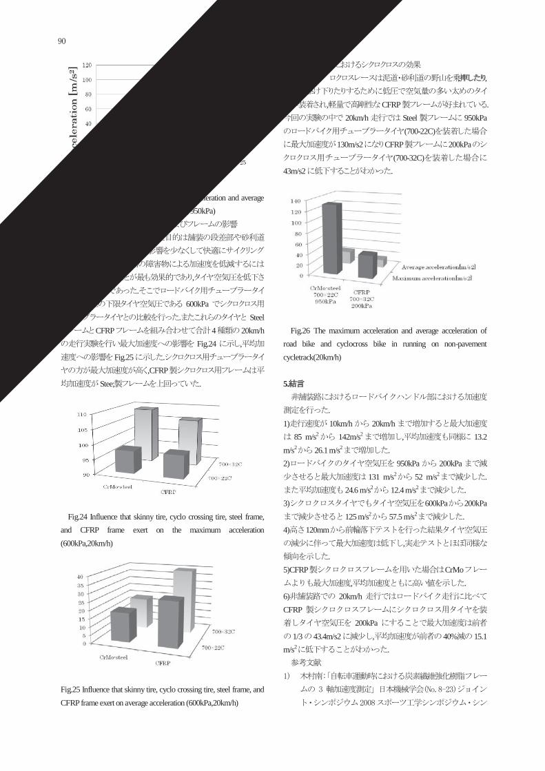
Fig.23 Relation of speed on the maximum acceleration and average acceleration(Steel frame, 700-22C road tire, 950kPa) 4-3
.,
.600kPa
. SteelCFRP 4 20km/h
Fig.24 ,Fig.25 .
,CFRPStee; .
Fig.24 Influence that skinny tire, cyclo crossing tire, steel frame, and CFRP frame exert on the maximum acceleration (600kPa,20km/h)
Fig.25 Influence that skinny tire, cyclo crossing tire, steel frame, and CFRP frame exert on average acceleration (600kPa,20km/h)
4-4 , ,
, CFRP .20km/h Steel 950kPa
(700-22C)130m/s2 CFRP 200kPa
(700-32C)43m/s2 .
Fig.26 The maximum acceleration and average acceleration of road bike and cyclocross bike in running on non-pavement cycletrack(20km/h)
5.
. 1) 10km/h 20km/h
85 m/s2 142m/s2 , 13.2 m/s2 26.1 m/s2 . 2) 950kPa 200kPa
131 m/s2 52 m/s2 .24.6 m/s2 12.4 m/s2 .
3) 600kPa 200kPa125 m/s2 57.5 m/s2 .
4) 120mm,
. 5)CFRP CrMo
, . 6) 20km/hCFRP
200kPa1/3 43.4m/s2 , 40% 15.1
m/s2 .
90 東京工業高等専門学校研究報告書(第44(1)号)

91木村:自転車乗車時の加速度測定~非舗装路におけるタイヤ空気圧の影響~

92 東京工業高等専門学校研究報告書(第44(1)号)
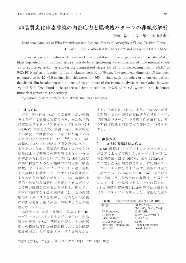
* ** ***
*, **, ***
Nonlinear Analysis of Film Breakdown and Internal Stress of
Amorphous Silicon Carbide Films Hiroshi ITO*, Yoshio KAWAMATA** and Masanori OHYAMA***
Internal stress and nonlinear dimension of film breakdown for amorphous silicon carbide (a-SiC) films
deposited onto the fused silica substrate by rf-sputtering were investigated. The internal stress σT of sputtered a-SiC has shown the compressed stress for all films decreasing from 1.34x10⁹ to 0.62x10⁹ Nm-2 as a function of film thickness from 40 to 760nm. The nonlinear dimension D has been evaluated to be 1.7~1.0 against film thickness 40~760nm since such the behavior of surface pattern density of film breakdown can be treated as an object of the fractal analysis. A correlation between σT and D is first found to be expressed by the relation log(D)=A σT B, where a and b denote numerical constants, respectively.
(Keywords: Silicon Carbide, film stress, nonlinear analysis)
SiC
2.83.0eV
SiC1,2) SiC
SiC
3,4) SiC
SiC
SiC
RF
a-SiC
SiC
a-SiC RF
1600 120kg/cm2
SiC1
120mm 20 0.5mm3
X
a-SiC
Table 1 Sputtering conditions of a-SiC film Target SiC(99.97%)
ITO[InO3, SnO2(5%)] RF Frequency 13.56 MHz RF Power 600W (3.29W/cm2) Base Pressure 1 10-3 Pa Ar Gas Pressure 0.1 Pa Substrate Temperature Room Temperature Substrate Fused Quartz
93東京工業高等専門学校研究報告書 第44(1)号,2012
Internal stress and nonlinear dimension of fi lm breakdown for amorphous silicon carbide(a-SiC) fi lms deposited onto the fused silica substrate by rf-sputtering were investigated. The internal stress σT of sputtered a-SiC has shown the compressed stress for all films decreasing from 1.34x10⁹ to 0.62x10⁹ N/m2 as a function of fi lm thickness from 40 to 760nm. The nonlinear dimension D has been evaluated to be 1.7~1.0 against fi lm thickness 40~760nm since such the behavior of surface pattern density of fi lm breakdown can be treated as an object of the fractal analysis. A correlation between σT and D is first found to be expressed by the relation log(D)=AσT+B, where a and b denote numerical constants, respectively.Keywords : Silicon Carbide, fi lm stress, nonlinear analysis
非晶質炭化珪素薄膜の内部応力と膜破壊パターンの非線形解析伊藤 浩*,川又由雄**,大山昌憲***
Nonlinear Analysis of Film Breakdown and Internal Stress of Amorphous Silicon Carbide FilmsHiroshi ITO*, Yoshio KAWAMATA** and Masanori OHYAMA***
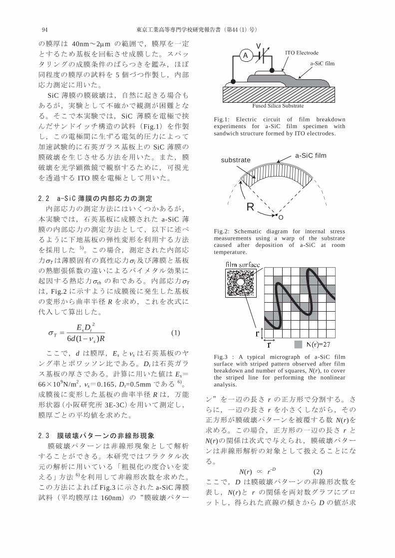
40nm 2 m
5
SiC
SiCFig.1
SiC
ITO
a-SiC
5)
T i
th T
Fig.2R
RdDE
s
tsT )1(6
2
(1)
d Es s
Dt
Es
66 109N/m2s 0.165 Dt=0.5mm 6)
R3E-3C
6)
Fig.3 a-SiC160nm
rr
N(r)r
N(r)
N(r) r-D (2)
DN(r) r
D
Fig.3 : A typical micrograph of a-SiC film surface with striped pattern observed after film breakdown and number of squares, N(r), to cover the striped line for performing the nonlinear analysis.
Fig.2: Schematic diagram for internal stress measurements using a warp of the substrate caused after deposition of a-SiC at room temperature.
RO
a-SiC film substrate
Fig.1: Electric circuit of film breakdown experiments for a-SiC film specimen with sandwich structure formed by ITO electrodes.
94 東京工業高等専門学校研究報告書(第44(1)号)
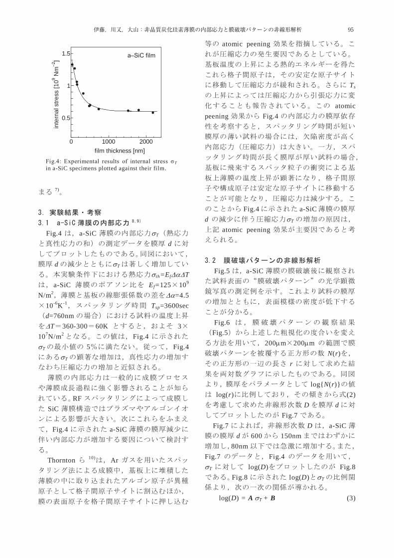
7)
Fig.4 a-SiC T
d
d T
th=Ef Ta-SiC Ef=125 109
N/m2 =4.510-6K-1 Tsp=3600secd=760nm
T 360-300 60K 3107N/m2 Fig.4
T 5 Fig.4T
RFSiC
Fig.4 a-SiC
Thornton 10) Ar
atomic peening
Ts
atomic peening Fig.4
Fig.4 a-SiCd T
atomic peening
Fig.5 a-SiC
Fig.6
Fig.5200 m 200 m
N(r)r
log{N(r)}log(r) (2)
D dFig.7
Fig.7 D a-SiCd 600 150nm
80nmFig.7 Fig.4
T log(D) Fig.8Fig.8 log(D) T
log(D) = A T + B (3)
0 1000 2000
0.5
1
1.5 a–SiC film
film thickness [nm]
inte
rnal
stre
ss [1
09 Nm
–2]
Fig.4: Experimental results of internal stress σT in a-SiC specimens plotted against their film.
95伊藤,川又,大山:非晶質炭化珪素薄膜の内部応力と膜破壊パターンの非線形解析

A BA=0.71(m2/N), B=-0.3
a-SiC T
D(3)
Fig.9 Fig.7 d
D
Fig.9d 100nm
100nm
0.91 2 3 4 5 6 7 8 9
2
3
4
log(r) [ m]
log(
N(r)
)
d=40nm80nm
160nm
600nm
400nm500nm
275nm
Fig.6: Plots of logN(r) vs. log r. N(r) denotes number of square covering striped pattern carved on surface of a-SiC specimen and r is a side length of their square.
0 200 400 600
1
1.5
2
nonl
inea
r di
men
sion
D
film thickness [nm]
a−SiC film
Fig.7: Plots of the nonlinear dimension vs. the film thickness of the a-SiC films on fused silica by rf-sputtering.
(a)
(c) (d)
(b)
200 [ m] 200 [ m]
200 [ m] 400 [ m]
Fig.5: Micrographs of striped pattern carved on a-SiC film surface after high-electric-field breakdown. It is found that the density of the striped pattern is lowered with increasing film thickness d.
0.8 1 1.2 1.4
0
0.1
0.2
0.3
internal stress T [x109 Nm–2]
log(
D)
a–SiC film
Fig.8: Semi-log plots of nonlinear dimension D against experimental internal stress.
Fig.9: Plots of log(D) vs. log(d). This figure is used data points in Fig.7 showing a relation of the nonlinear dimension and the film thickness.
200 [ m]
0 200 400 600
1
1.5
2
nonl
inea
r dim
ensi
on D
film thickness [nm]
a SiC film
Fig.7: Plots of the nonlinear dimension vs. the film thickness of the a-SiC films on fused silica by rf-sputtering.
0.8 1 1.2 1.4
0
0.1
0.2
0.3
internal stress T [x109 Nm–2]
log(D
)
a–SiC film
Fig.8: Semi-log plots of nonlinear dimension D against experimental internal stress.
102 103
0.91
2
nonl
inea
r dim
ensi
on D
film thickness [nm]
a SiC film
96 東京工業高等専門学校研究報告書(第44(1)号)
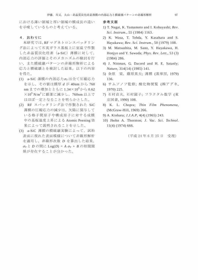
RF
a-SiC
(1) a-SiC T
d 40nm 760 nm 1.34 109 0.62
109 N/m2 760nm
(2) RF SiC
Atomic Peening
(3) a-SiC
DT D Log(D) = A T + B
1) T. Nagai, K. Yamamoto and I. Kobayashi; Rev. Sci. Instrum., 55 (1984) 1163.
2) K. Wasa, T. Tohda, Y. Kasahara and S. Hayakawa; Rev. Sci. Instrum., 50 (1979) 108.
3) M. Matsushita, M. Sano, Y. Hayakawa, H. Honjyo and Y. Sawada; Phys. Rev. Lett., 53 (3) (1984) 286.
4) J. Nittman, G. Dacord and H. E. Satanly; Nature, 314(14) (1985) 141.
5) ; ( , 1979) 136.
6) ; ( , 1970) 225.
7) , ; (, 1990) 108.
8) K. L. Chopra; Thin Film Phenomena, (McGraw-Hill, 1969) 266.
9) A. Kinbara; J.J.A.P, 4(4) (1965) 243. 10) Jhohn A. Thornton; J. Vac. Sci. Technol.
11(4) (1974) 666.
97伊藤,川又,大山:非晶質炭化珪素薄膜の内部応力と膜破壊パターンの非線形解析

98 東京工業高等専門学校研究報告書(第44(1)号)
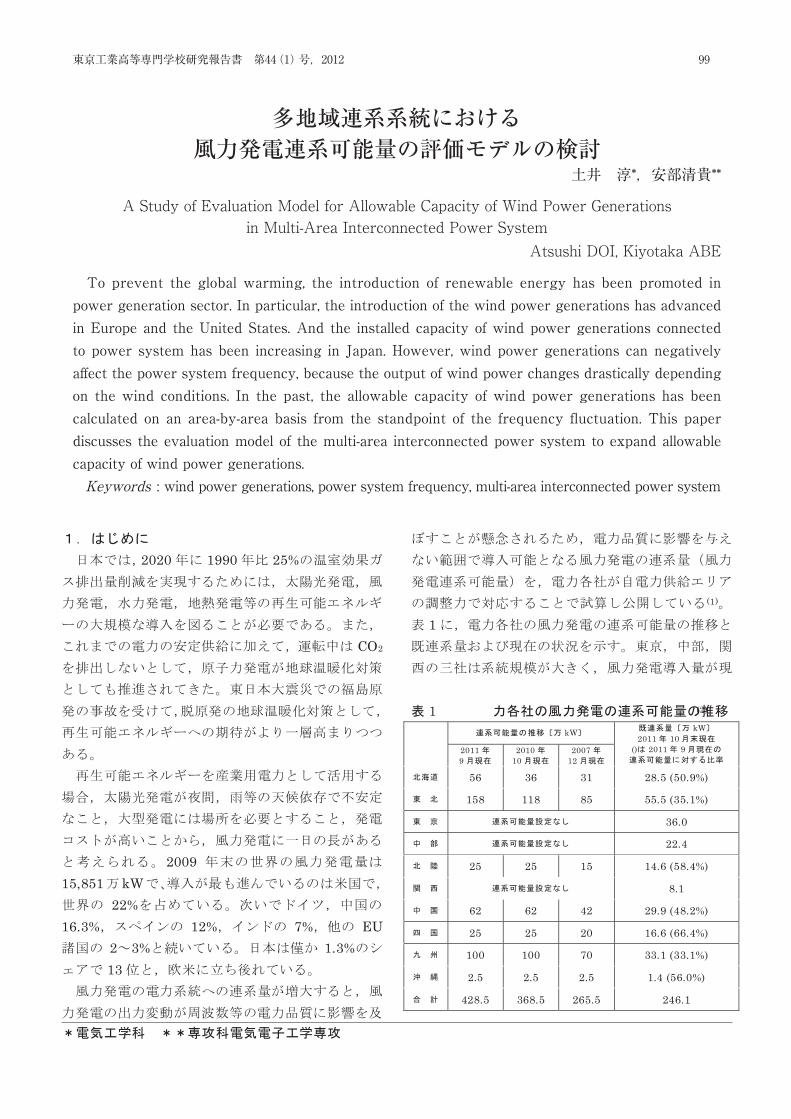
* **
A Study of Evaluation Model for Allowable Capacity of Wind Power Generations
in Multi-Area Interconnected Power System
Atsushi DOI, Kiyotaka ABE
To prevent the global warming, the introduction of renewable energy has been promoted in power generation sector. In particular, the introduction of the wind power generations has advanced in Europe and the United States. And the installed capacity of wind power generations connected to power system has been increasing in Japan. However, wind power generations can negatively affect the power system frequency, because the output of wind power changes drastically depending on the wind conditions. In the past, the allowable capacity of wind power generations has been calculated on an area-by-area basis from the standpoint of the frequency fluctuation. This paper discusses the evaluation model of the multi-area interconnected power system to expand allowable capacity of wind power generations.
(Keywords: wind power generations, power system frequency, multi-area interconnected power system)
2020 1990 25%
CO2
200915,851 kW
22%16.3% 12% 7% EU
2 3% 1.3%13
(1)
1
1 (2) kW kW
2011 10 () 2011 9
2011 9
2010 10
2007 12
56 36 31 28.5 (50.9%)
158 118 85 55.5 (35.1%)
36.0
22.4
25 25 15 14.6 (58.4%)
8.1
62 62 42 29.9 (48.2%)
25 25 20 16.6 (66.4%)
100 100 70 33.1 (33.1%)
2.5 2.5 2.5 1.4 (56.0%)
428.5 368.5 265.5 246.1
99東京工業高等専門学校研究報告書 第44(1)号,2012
To prevent the global warming, the introduction of renewable energy has been promoted in power generation sector. In particular, the introduction of the wind power generations has advanced in Europe and the United States. And the installed capacity of wind power generations connected to power system has been increasing in Japan. However, wind power generations can negatively aff ect the power system frequency, because the output of wind power changes drastically depending on the wind conditions. In the past, the allowable capacity of wind power generations has been calculated on an area-by-area basis from the standpoint of the frequency fluctuation. This paper discusses the evaluation model of the multi-area interconnected power system to expand allowable capacity of wind power generations.Keywords : wind power generations, power system frequency, multi-area interconnected power system
多地域連系系統における風力発電連系可能量の評価モデルの検討
土井 淳*,安部清貴**
A Study of Evaluation Model for Allowable Capacity of Wind Power Generationsin Multi-Area Interconnected Power System
Atsushi DOI, Kiyotaka ABE
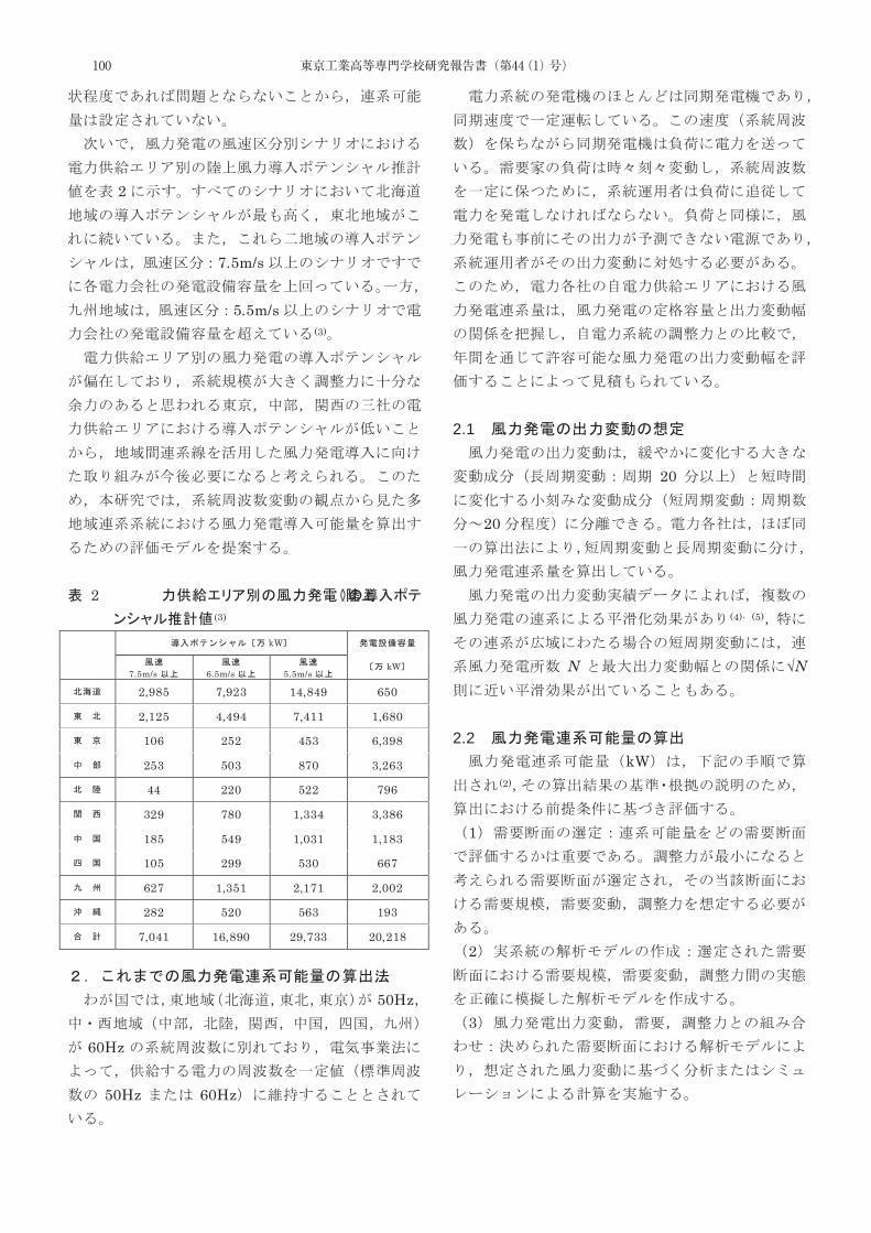
2
7.5m/s
5.5m/s(3)
2(3)
kW
kW 7.5m/s
6.5m/s
5.5m/s
2,985 7,923 14,849 650
2,125 4,494 7,411 1,680
106 252 453 6,398
253 503 870 3,263
44 220 522 796
329 780 1,334 3,386
185 549 1,031 1,183
105 299 530 667
627 1,351 2,171 2,002
282 520 563 193
7,041 16,890 29,733 20,218
50Hz
60Hz
50Hz 60Hz
2.1
20
20
(4) (5)
N √N
2.2
kW(2)
1
2
3
100 東京工業高等専門学校研究報告書(第44(1)号)
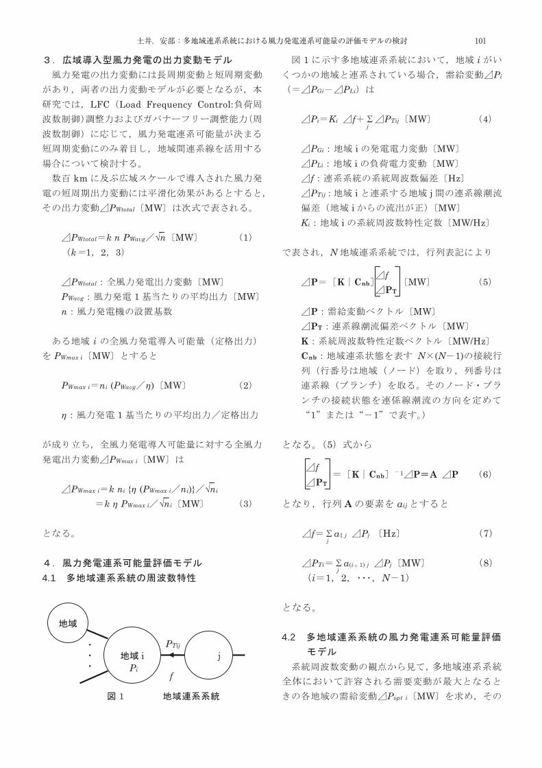
LFC Load Frequency Control:
km
PWtotal MW
PWtotal k n PWavg √n MW 1 k 1 2 3
PWtotal MW
PWavg 1 MW n
i
PWmax i MW
PWmax i ni (PWavg η) MW 2
η 1
PWmax i MW
PWmax i k ni {η (PWmax i ni)} √ni k η PWmax i √ni MW 3
4.1
1
1 iPi
PGi PLi
Pi Ki f PTij MW 4
PGi i MW PLi i MW f Hz PTij i j
i MW Ki i MW/Hz
N
P K Cnb MW 5
P MW PT MW
K MW/Hz Cnb N (N 1)
1 1
5
K Cnb 1 P A P 6
A aij
f a1 j Pj Hz 7
PTi a(i 1) j Pj MW 8 i 1 2 N 1
4.2
Popt i MW
i jPTij
Pi f
j
f PT
f PT
j
j
101土井,安部:多地域連系系統における風力発電連系可能量の評価モデルの検討

1 Pi MW
Ci Pi MW 9
Ci i
2
0.2Hz2σ 0.1Hz
f Hz7
0 f a1 j Pj Fmax 10
Fmax Hz
1 k 3 Fmax
0.2Hz k 2 Fmax 0.1Hz
PTi 8
PTmin i PTi
a(i 1) j Pj PTmax i 11
PTmax i i0 MW
PTmin i i0 MW
PTmax i MW
Pi MW
PGi MW PLi MW
Pi2 PGi2 PLi2 12
Pi MW PLi MW
PLi Pi 13
PLi MW
PLi k PLtotal i √PLtotal i k √PLtotal i 14 k 1 2 3
PLtotal i i MW
9 10 1113
Popt i MW
4.3
Popt i MW
PWopt i MW 12 Pi Popt i
Popt i2 PWopt i2 PLi2 15
i
j
j
102 東京工業高等専門学校研究報告書(第44(1)号)
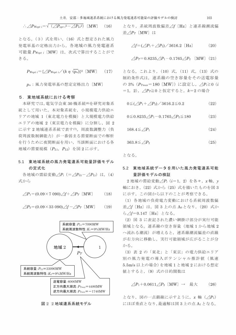
PWopt i √ Popt i2 PLi2 MW 16
16
PWopt i MW
PWopt i { PWopt i (k η √pn)}2 MW 17
pn MW
30 (6)
12 2
2 (7)
PL1 PL2 2 5.1
Pi PGi PLi 4
P1 (0.09 7 090) f PT MW 18
P2 (0.09 33 090) f PT MW 19
2 2
f HzPT MW
f ( P1 P2) 3616.2 Hz 20
PT 0.8235 P1 0.1765 P2 MW 21
10 11 13
3% PTmax 180 MW Pi 0 i1 2 PT 0 k 2
0 ( P1 P2) 3616.2 0.2 22 0 0.8235 P1 0.1765 P2 180 23 168.4 P1 24 363.8 P2 25
5.2
2 Pi i 1 2 x y22 25 3
1
f Hz 3 A0 20f 0.147 Hz
2 31 2
3 2
5.5m/s 1 29
P1 0.0611 P2 MW 26
x P1
3 A1
2 1PT
PL1 7090MW K1 9%MW/Hz
PL2 33090MW K2 9%MW/Hz
6000MW PTmax 4480MW PTmin 1740MW
103土井,安部:多地域連系系統における風力発電連系可能量の評価モデルの検討
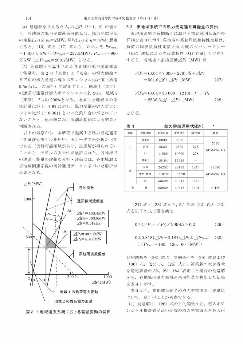
4 A1 Pi i 1 2
pn 2MW η 75%16 17 PWmax1
1 400 kW PWopt1 257.5MW PWmax2 900kW PWopt2 200.7MW 5
2
5.5m/s 120% 2
200% 1 21 4.671 0.0611
3 2
5.3(7)
3
GF GFPi MW
P1 (0.04 7 090 278) f PT
561.6 f PT MW 27
P2 (0.04 33 090 1213) f PT
2536.6 f PT MW 28
3 MW GF
1
6000 5800 7090
(4%MW/Hz) 5560 4800 278
11560 10600 278
2
18184 17325
33090
(4%MW/Hz)
24252 22192 1213
11073 9270
53509 30247 1213
65069 40847 1491 40180
27 28 5.1 22 23
0 ( P1 P2) 3098.2 0.2 29
0 0.8187 P1 0.1813 P2 PTmax 30
PTmax 180 120 60 MW
26 2930 24 25
3% 2% 1%
4 4
1 26
P1 MW
P2 MW
O
500
500 1000
1000
P1 307.7MW P2 415.5MW
P1 168.4MW P2 363.8MW f 0.147Hz
1
2
A1
A0
104 東京工業高等専門学校研究報告書(第44(1)号)
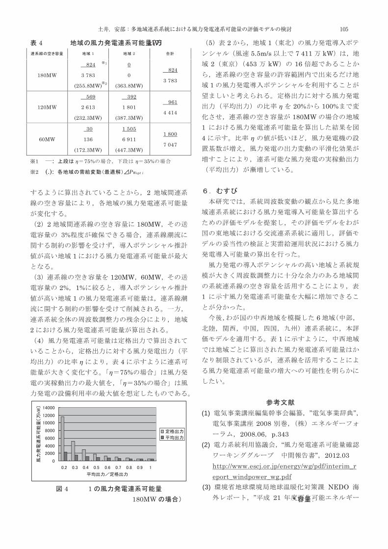
4 kW 1 2
180MW
824
3 783
(255.8MW)
0
0
(363.8MW)
824
3 783
120MW
569
2 613
(232.3MW)
392
1 801
(387.3MW)
961
4 414
60MW
30
136
(172.3MW)
1 505
6 911
(447.3MW)
1 800
7 047
1 : η 75% η 35%
2 (.): PWopt i
2
2 2 180MW
3%
1
3 120MW 60MW2% 1%
1
2 4
η 4η 75%
η 35%
4 1
180MW
5 2 15.5m/s 7 411 kW
2 453 kW 16
1
η 20% 100%180MW
14 η
1
6
1
(1) ” ”2008
2008.06 p.343 (2) “
” 2012.03 http://www.escj.or.jp/energy/wg/pdf/interim_report_windpower_wg.pdf
(3) NEDO” 21
1
2
105土井,安部:多地域連系系統における風力発電連系可能量の評価モデルの検討

” 2010.03 http://www.env.go.jp/earth/report/h22-02/full.pdf
(4) ”
” B 129 5 2009.05 pp.661667
(5) ”
” 24 6-0062012.03 6 pp.9 10
(6) ”” 754
1999. (7) ”FFC-TBC
” B 128 7 2008.07pp.953 960
24 7 19
106 東京工業高等専門学校研究報告書(第44(1)号)
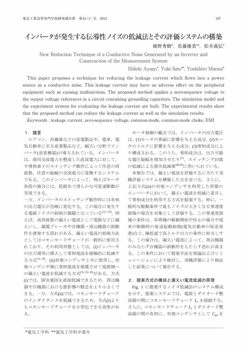
New Reduction Technique of a Conductive Noise Generated by an Inverter and Construction of the Measurement System
Hideki Ayano Yuki Sato Yoshihiro Matsui
This paper proposes a technique for reducing the leakage current which flows into a power source as a
conductive noise. This leakage current may have an adverse effect on the peripheral equipment such as causing malfunctions. The proposed method applies a zero-sequence voltage to the output voltage references in a circuit containing grounding capacitors. The simulation model and the experiment system for evaluating the leakage current are built. The experimental results show that the proposed method can reduce the leakage current as well as the simulation results. Keywords: leakage current, zero-sequence voltage, common-mode, common-mode choke, EMI
( )
(1) (3)
(i)
(1) (4) (ii) ,
(3) (5) (6)
(i)
(ii)(i)
(1) (2)(3)
(7)
(8) (9)
(ii)
()
Fig. 1
Lc
Lc
Cga
* **
107東京工業高等専門学校研究報告書 第44(1)号,2012
This paper proposes a technique for reducing the leakage current which flows into a power source as a conductive noise. This leakage current may have an adverse eff ect on the peripheral equipment such as causing malfunctions. The proposed method applies a zero-sequence voltage to the output voltage references in a circuit containing grounding capacitors. The simulation model and the experiment system for evaluating the leakage current are built. The experimental results show that the proposed method can reduce the leakage current as well as the simulation results.Keywords : leakage current, zero-sequence voltage, common-mode, common-mode choke, EMI
インバータが発生する伝導性ノイズの低減法とその評価システムの構築綾野秀樹*,佐藤優貴**,松井義弘*
New Reduction Technique of a Conductive Noise Generated by an Inverter andConstruction of the Measurement System
Hideki Ayano*, Yuki Sato**, Yoshihiro Matsui*
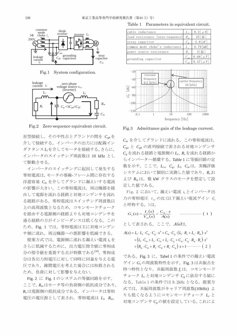
Cgb
Ll
10 kHz
-Cm
Fig. 1
ic
(10)
Fig. 2 Fig. 1
Rm
Rs
Ll Rm
Cm
Cga Cgb
Cg Lc Rs
Table 1Lc, Cg Ll Cm
Rs
Rm kW
ic
1)(
)(sA
sCsVsI
sG m
zo
cs
A(s)
21
)(2
34
sCRCRCRsRRCCCLCLCL
sRLRLCCsCCLLsA
gsmsmm
smgmgcmcml
mcslgmgmcl
Fig. 3 Tabel 1
Gs Fig. 3fc
Lc Cg
(10kHz) Lc
Cg
Fig.2 Zero-sequence equivalent circuit.
Ll
Cm
RmCg =3Cga//Cgb
Lc
Rs
iczero phase
voltage source vo(inverter)
leakagecurrent
Table 1 Parameters in equivalent circuit.
Fig.3 Admittance gain of the leakage current.
Fig.1 System configuration.
3Φ200V
dioderectifier inverter
groundingcapacitors
Cga
Cgb
commonmodechoke
ic
leakagecurrent
stray capacitor
Cm
L
………………
…………
108 東京工業高等専門学校研究報告書(第44(1)号)
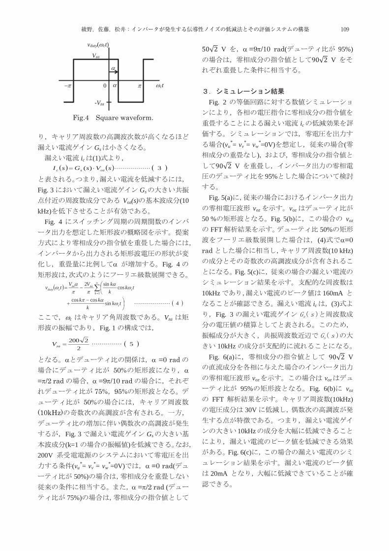
Gs ic (1)
3)( sVsGsI ozsc
Fig. 3 Gs
Voz(s) (10 kHz)
Fig. 4
Fig. 4
4sincoscos
cossin21
tkk
kk
tkkkVVtv
c
kc
zazacduty
c Vza
Fig. 1
52
2200zaV
=0 rad50%
= /2 rad =9 /10 rad75% 95%
50%(10kHz)
Fig. 3 Gs
(k=1 )200V
(vu*= vv
*= vw*=0V) =0 rad(
50%) = /2 rad (
75%)
50√2 V =9 /10 rad( 95%)90√2 V
Fig. 2
ic
(vu*= vv
*= vw*=0V) ()90√2 V
95%
Fig. 5(a)voz voz
50 % Fig. 5(b) voz FFT 50%
(4) =0 rad (10 kHz)
Fig. 5(c)
10kHz 160mA ic (3)
Fig. 3
10kHz Fig. 6(a) 90√2 V
voz voz
95% Fig. 6(b) voz
FFT (10kHz)30V
10kHz
Fig. 6(c)
20mA
Fig.4 Square waveform.
ct
vduty( ct)
Vza
-Vza
………………
………………
……………
109綾野,佐藤,松井:インバータが発生する伝導性ノイズの低減法とその評価システムの構築
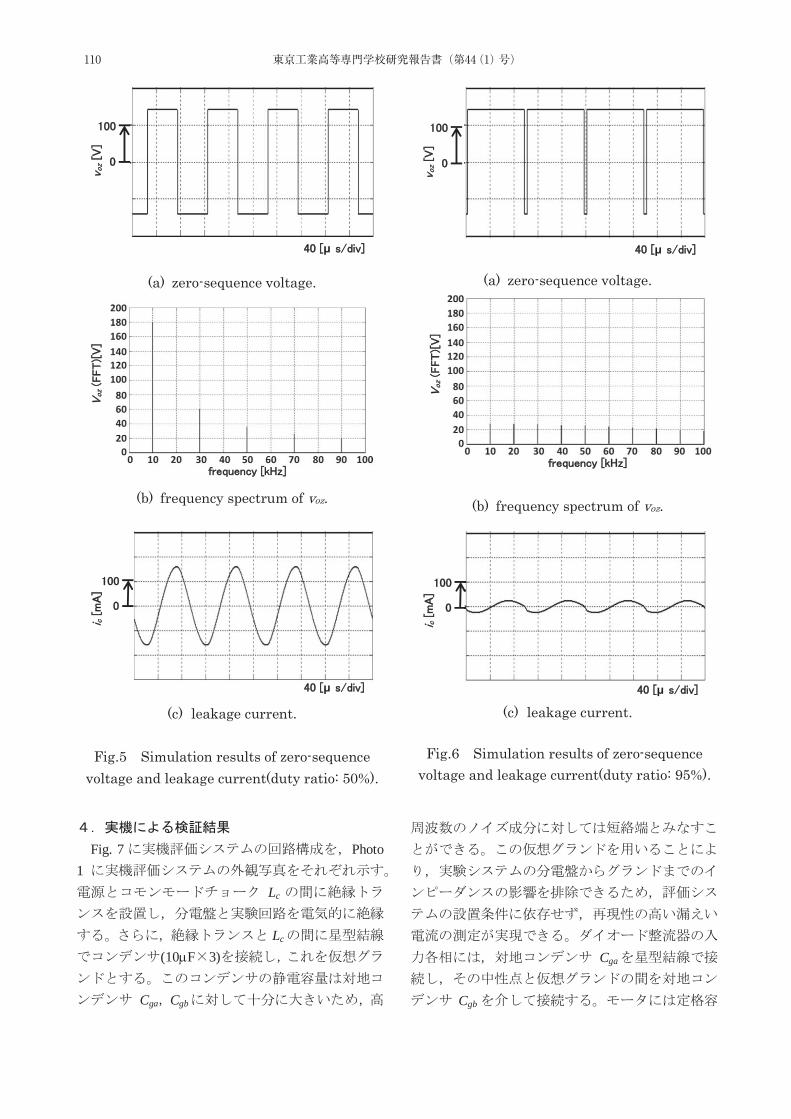
Fig. 7 Photo 1
Lc
Lc
(10 F 3)
Cga Cgb
Cga
Cgb
(a) zero-sequence voltage.
(b) frequency spectrum of voz.
(c) leakage current.
Fig.5 Simulation results of zero-sequence
voltage and leakage current(duty ratio: 50%).
μ
μ
(a) zero-sequence voltage.
(b) frequency spectrum of voz.
(c) leakage current.
Fig.6 Simulation results of zero-sequence
voltage and leakage current(duty ratio: 95%).
μ
μ
110 東京工業高等専門学校研究報告書(第44(1)号)
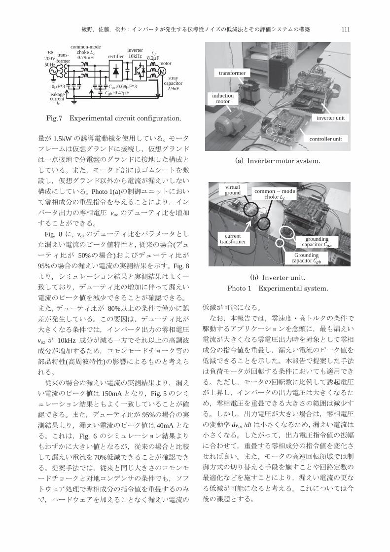
1.5kW
Photo 1(a)
voz
Fig. 8 , voz
(50% )
95% Fig. 8
80%
voz 10kHz
( )
150mA Fig. 5
95%40mA
Fig. 6
70%
dvoz /dt
Fig.7 Experimental circuit configuration.
rectifierinverter10kHz
common-mode choke 0.79mH
ic
leakagecurrent
stray capacitor
2.9nF
3Φ200V50Hz
trans-former
Cga :0.68 F*3Cgb :0.47 F
8.2 Fmotor
F*3
(a) Inverter-motor system.
(b) Inverter unit. Photo 1 Experimental system.
induction motor
transformer
inverter unit
controller unit
groundingcapacitor
Groundingcapacitor
cvirtualground
currenttransformer
111綾野,佐藤,松井:インバータが発生する伝導性ノイズの低減法とその評価システムの構築
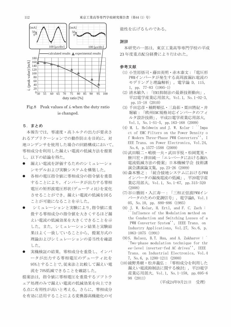
23
Fig.8 Peak values of ic when the duty ratio is changed.
i c(p
eak
valu
e) [m
A] 180
160140120100
80604020
0
duty ratio [%]50 55 60 65 70 75 80 85 90 95 100
calculated results experimental results
100 [ s/div] 100 [ s/div]
[mA] [mA]500
500
112 東京工業高等専門学校研究報告書(第44(1)号)

1.
* 物質工学科
1.
.
1)2).
.
.
3).
.604).
Pseudokirchneriellasubcapitata Daphnia magna Oryzias latipes
1)4). 3
113東京工業高等専門学校研究報告書 第44(1)号,2012
Recently, heavy metals have been used in the various products, though they have strong toxicity
to organisms. Toxicity of 60 elements against organisms such as fishes, daphnids and algae in
fresh water have not been elucidated yet. The objectives of this study are to elucidate the toxicity
of 60 elements by toxicity tests using organisms in diff erent stages in ecosystem, and to perform
the Quantitative Structure Activity Relationship(QSAR)approach which is for the prediction
of the toxicity of metals from their own properties such as σp(softness index)and ion radius to
the prediction of toxicity of unknown metals. A clear relationship of toxicity among organisms in
different stages in ecosystem was found. The toxic effects of metals to Oryzias latipes, Daphnia
magna and Pseudokirchneriella subcapitata were correlated with σp and ion radius of the metals.
Keywords : Ecotoxicity, Toxicity test, EC50, LC50, Food Chain, Ecological Pyramid
構造活性相関を用いた重金属の生態毒性の生物間の比較
庄司 良*,島袋将弥*,高橋 萌*
Analysis on toxicity of heavy metals against organisms in diff erent stagesin whole ecosystem by QSAR(Quantitative Structure Activity Relationship)
Ryo SHOJI, Masaya SHIMABUKURO, Moe TAKAHASHI

2.3.
2.4.
2.5. QSAR
.-
3)5).
6).
.
(QSAR)2).
7)
.
.
P. subcapitata D. magna O. latipes
.
22. 2.1.
P. subcapitata D. magna O. latipesEC50[ mol/L](50%
) LC50[ mol/L](50% )ECOTOX Database8) MSDS(Material Safety Data Sheet)
.ECOTOX Database[1]
[2] 72 48 96[3]
[4]
.
2.2.
2 3 P. subcapitata ( ) OECD
.22 72
(SHIMADZU UV-1200)655nm
. μ Im(%) (1) (2).t 1
[h] t n n[h] N1 t 1
[cells/ml] Nn tn
[cells/ml] μc μt
. μ (lnNn - lnN1)/(tn - t1)×100 (1) Im=(μc - μt)/μc×100 (2)
Table 1 AAP.
114 東京工業高等専門学校研究報告書(第44(1)号)
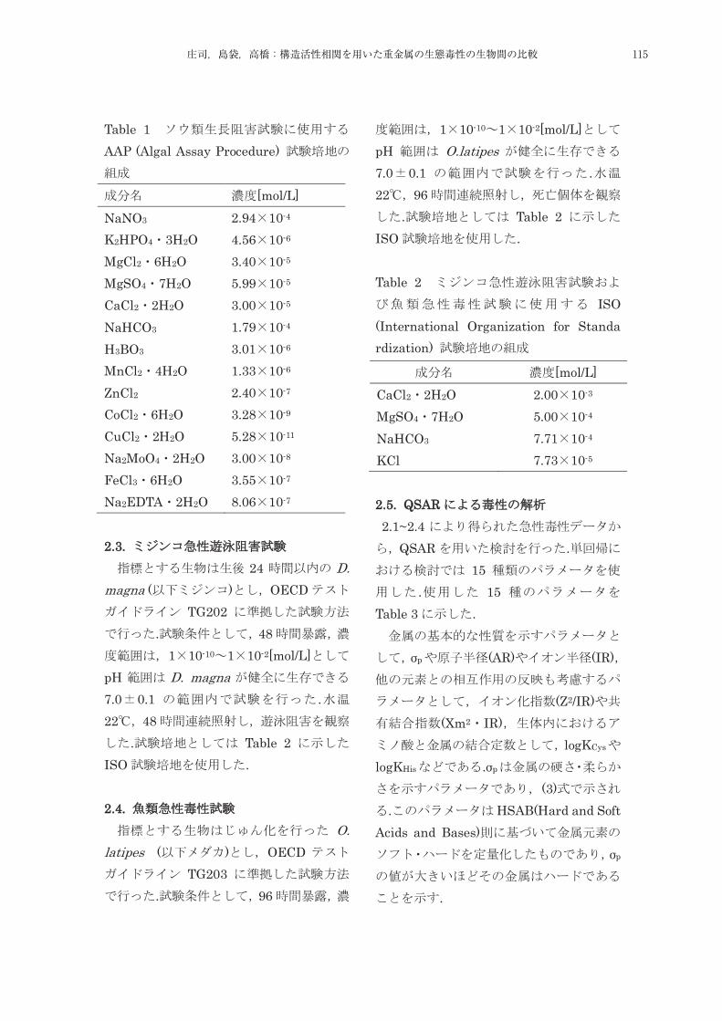
Table 1 AAP (Algal Assay Procedure)
[mol/L]
NaNO3 2.94 10-4 K2HPO4 3H2O 4.56 10-6 MgCl2 6H2O 3.40 10-5 MgSO4 7H2O 5.99 10-5 CaCl2 2H2O 3.00 10-5 NaHCO3 1.79 10-4 H3BO3 3.01 10-6 MnCl2 4H2O 1.33 10-6 ZnCl2 2.40 10-7 CoCl2 6H2O 3.28 10-9 CuCl2 2H2O 5.28 10-11 Na2MoO4 2H2O 3.00 10-8 FeCl3 6H2O 3.55 10-7 Na2EDTA 2H2O 8.06 10-7
22.3.
24 D. magna ( ) OECD
TG202 . 48
1 10-10 1 10-2[mol/L]pH D. magna7.0 0.1 .22 48
. Table 2ISO . 2.4.
O. latipes ( ) OECD
TG203. 96
1 10-10 1 10-2[mol/L]pH O.latipes7.0 0.1 .22 96
. Table 2ISO . Table 2
ISO (International Organization for Standa rdization)
2.5. QSAR 2.1~2.4
QSAR .15
. 15Table 3 .
σp (AR) (IR)
(Z2/IR)(Xm2 IR)
logKCys
logKHis .σp
(3). HSAB(Hard and Soft
Acids and Bases)σp
.
[mol/L] CaCl2 2H2O 2.00 10-3 MgSO4 7H2O 5.00 10-4 NaHCO3 7.71 10-4 KCl 7.73 10-5
2. 2.1.
2.2.
115庄司,島袋,高橋:構造活性相関を用いた重金属の生態毒性の生物間の比較
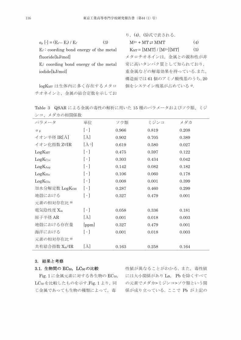
σp [-] = (Ef – Ei) / Ef (3) Ef : coording bond energy of the metal fluoride[kJ/mol] Ei: coording bond energy of the metal iodide[kJ/mol] logKMT
(4) (5) . M2+ + MT ⇄ MMT (4)
KMT = [MMT] / [M2+][MT] (5)
.61 20
4).
Table 3 QSAR 15
p [ - ] 0.966 0.819 0.208 IR[ ] [ ] 0.902 0.705 0.389
Z2/IR [ -1] 0.619 0.580 0.027 LogKMT [ - ] 0.475 0.597 0.122 LogKCys [ - ] 0.303 0.434 0.042 LogKAsp [ - ] 0.142 0.082 0.182 LogKHis [ - ] 0.106 0.060 0.178 LogKGlu [ - ] 0.008 0.001 0.399
LogKOH [ - ] 0.287 0.460 0.299
9) [ - ] 0.327 0.479 0.001
Xm [ - ] 0.058 0.336 0.181 AR [ ] 0.001 0.018 0.003
[ppm] 0.327 0.479 0.001
9) [ - ] 0.001 0.018 0.003
Xm2IR [ ] 0.163 0.258 0.164 33. 3.1. EC50 LC50
Fig. 1 EC50
LC50 .Fig. 1
.
La Pb> >
. Pb
116 東京工業高等専門学校研究報告書(第44(1)号)

PbCl2 10).
μ
Fig. 1 EC50 LC50
.
.
. La LaCl3
10). La
.
.La3+
11)
. Fig. 2EC50
EC50 . (factor) Fig. 2
.
μ
μ
Fig. 2 EC50
EC50 Fig. 2 EC50
EC50 R2=0.921 .
( ) 0.1~10
.=1
.=1
2 LaPb La Pb
. Fig. 1
3. 3.1. EC50 LC50
117庄司,島袋,高橋:構造活性相関を用いた重金属の生態毒性の生物間の比較
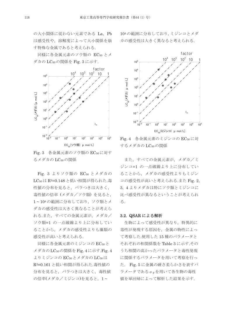
La Pb
. EC50
LC50 Fig. 3 .
μ
μ
Fig. 3 EC50
LC50
Fig. 3 EC50
LC50 R2=0.148 .
( ) 1 ~ 104
.=1
. EC50
LC50 Fig. 4 .Fig. 4EC50 LC50
R2=0.161 .
( ) 1 ~
104
.
μ
μ
Fig. 4 EC50
LC50
=1
. Fig. 23 4
.
33.2. QSAR
. 15Table 3 .
. Fig. 5p
.
118 東京工業高等専門学校研究報告書(第44(1)号)
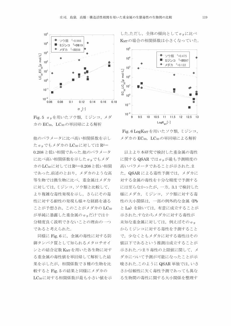
μ
σ
Fig. 5 p
EC50 LC50
p LC50 R2
0.208 .p
LC50 R2 0.208.
LC50
p
. Fig. 6
KMT
3Fig. 5
LC50
. p
KMT .
μ
Fig. 6 LogKMT
EC50 LC50
QSAR p
.QSAR
3.1
(PbLa)
.p
.
. QSAR
3.2. QSAR
119庄司,島袋,高橋:構造活性相関を用いた重金属の生態毒性の生物間の比較
.
. 44. 1)
vol. 12 No. 10 pp. 654-663 1989. 2)
vol. 16No. 3 pp. 63-84 2006 3)
pp. 14-19 1998. 4)
(QSAR)
vol. 3 pp. 226-2272011 5)
vol. 56 pp. 240-251 2006
6) –
-vol. 33 No. 1 pp. 1-10 1987 7) Zhao et al. QSAR study of the toxicity of benzoic acids to Vibrio fischeri, Daphnia magna and carp The Science of the Total Environment vol. 216 pp. 205-215 1998
8) ECOTOX Database US.EPA 9)
pp. 104-105 2003. 10)
pp. 90-91 1964 11)
NMCCvol. 10 pp. 103-106 2002
25 9 25
120 東京工業高等専門学校研究報告書(第44(1)号)

121121東京工業高等専門学校研究報告書 第44(1)号,2012
平成23年度教員教育研究業績
1.研究論文・著作物・(著書・翻訳書等)
一般教育科一般教育科
戦後中小企業政策における組織化政策の展開 -中小企業等協同組合法制定を巡る議論を中心に
(『東京工業高等専門学校研究報告書』第 43(2)号,2012.3,pp.9-18) ・・・・・・・・・・・・・・・・・・浅野敬一浅野敬一
占領初期日本社会党の中小企業政策 -1947 年総選挙を中心に-
(『社会経済史学』第 77 巻第 4号,2012.3,pp.95-110) ・・・・・・・・・・・・・・・・・・・・・・・・浅野敬一浅野敬一
技術者倫理教育の立場から東日本大震災を考える
(『東京工業高等専門学校研究報告書』第 43(1)号 2011.12,pp.5-22)
・・・・・・・・・・・・・・・・・・・・・・・・・・・・・・・・河村豊河村豊,川北晃司,浅野敬一浅野敬一,木村南木村南,庄司良庄司良
「中国科学技術政策史」 の試み (その1)
(『東京工業高等専門学校研究報告書』第 43(2)号,2012,pp.19-30) ・・・・・・・・・・・・・・・・・・・河村豊河村豊
二高専における学生の体格 ・ 体力の比較検討
(『高専教育』第 35 号,2012,pp.559-564)・・・・・鈴木智之鈴木智之,古屋正俊古屋正俊,黒田一寿黒田一寿,内山了治,児玉英樹,石川美久
『論語』 子罕篇 「歳寒の松」 の解釈とその受容について
(『東京工業高等専門学校研究報告書』第 43(1)号,2011.12,pp.1-9) ・・・・・・・・・・・・・・・・・・・津田潔津田潔
Femtosecond-laser-driven photoelectron-gun for time-resolved cathodoluminescence measurement of GaN
(『Review of Scientifi c Instruments』83,2012,pp.043905 1-7)
・・・・・・ Takeyoshi ONUMATakeyoshi ONUMA,Yuji KAGAMITANI,Koji HAZU,Tohru ISHIGURO,Takeo FUKUDA,and Shigefusa
F.CHICHIBU
Learning a Foreign Language from a Busy Person's Perspective -Part 2: Observations from the First Six Months-
(『東京工業高等専門学校研究報告書』第 43(1)号,2011.12,pp.1-4) ・・・・・・・・・・・・・・・・・ John GatesJohn Gates
Learning a Foreign Language from a Busy Person's Perspective -Part 3: Observations from the First Year-
(『東京工業高等専門学校研究報告書』第 43(2)号,2012.3,pp.1-4) ・・・・・・・・・・・・・・・・・ John GatesJohn Gates
3.11 震災報道にみる対日イメージ分析
(『日英言語文化研究』第 3号,2012.6,pp.51-62) ・・・・・・・・・・・・・・・・・・・・・・・・・関根紳太郎関根紳太郎
国語プレースメントテストの実施報告
(『東京工業高等専門学校研究報告書』第 43(1)号,2011.12,pp.23-27) ・・・・・・・舩戸美智子舩戸美智子,川北晃司,津田潔津田潔
Japanese EFL Learners' Tendency Toward Syntactic Production in a Picture-Description Task: Establishing a Baseline for Syntactic
Priming Experiments
(『大学英語教育学会中部支部紀要』第 9号,2012.3,pp.141-154)
・・・・・・ Kaori SUGIURA,Ai HIRAI,Tomoko HORITomoko HORI,Hiroshi NAKANISHI,Emiko IZUMI,Tomoko SAITO,Shuhei
KADOTA,Hisaki SATOI,Yoko MORISHITA,Satoshi YABUUCHI
日本人英語学習者における聴覚性プライミング効果 -単語復唱課題による検討
(『関東甲信越英語教育学会誌』第 26 号,2012.3,pp.39-50)・・・・・・・・・・・・・・・・・・杉浦香織,堀智子堀智子
福島第一原子力発電所事故を高専でどう教えるか
(『東京工業高等専門学校研究報告書』第 43(2)号,2012.3,pp.5-7) ・・・・・・・・・・・・・・・・・・前段眞治前段眞治
Enhancing Pronunciation Learning through a Web-based Tutorial
(『情報学研究』獨協大学情報学研究所,創刊号,2012.2,pp.53-59) ・・・・・・・・・・・・・青木理沙,樫村真由樫村真由
ヴィクトリア朝の幽霊物語 クリスマスと光学技術
(『ヘルメスたちの饗宴』音羽書房鶴見書店,2012.3,pp.428-448) ・・・・・・ 松島正一編,樫村真由樫村真由(第 22 章担当)
機械工学科機械工学科
CFRP サンドイッチパネルの試作とそのワイヤカット放電加工
(『自動車技術論文集』vol.43,No.1(2012)pp.153-158) ・・・・・・・・・木村南木村南,鹿窪勇太,熊澤禎乃,成瀬太一
走行時自転車フレームの 3 軸加速度測定
(『東京工業高等専門学校研究報告書』第 43 巻(1)号,2011,pp.51-56) ・・・・・・・・・・・・・・・・・・木村南木村南
高専 ・ 専攻科における炭素繊維強化プラスチックを用いたものづくり
(『塑性と加工』52 巻・611 号,pp.58-59) ・・・・・・・・・・・・・・・・・・・・・・・・・・・・・・・木村南木村南
Effects of the Air Volume in the Air Chamber on the Performance of Water Hammer Pump
(『International Journal of Fluid Machinery and Systems』Vol.4,No.2,2011,pp.255-261)
・・・・・・・・・・・・・・・・・・・・・・・・・・・・・・ Sumio SaitoSumio Saito,Masaaki Takahashi,Yoshimi Nagata
水撃ポンプシステムの特性に及ぼす排水弁まわりの形状因子の影響
(『ターボ機械』39 巻 6 号,2011.6,pp.323-331) ・・・・・・・・・・・・斉藤純夫斉藤純夫,高橋正旭,永田佳未,出嶌京太
水撃ポンプの揚水弁部の開口面積が性能に及ぼす影響と弁室内流れの挙動
(『ターボ機械』39 巻 8 号,2011.8,pp.449-457) ・・・・・・・・・・・・斉藤純夫斉藤純夫,出嶌京太,高橋正旭,土方我久
122 東京工業高等専門学校研究報告書(第44(1)号)
Effects of the Geometry of Components Attached to the Drain Valve on the Performance of Water Hammer Pumps
( 『International Journal of Fluid Machinery and Systems』Vol.4,No.4,2011,pp.367-374)
・・・・・・・・・・・・・・・・・・・・・・・ Sumio SaitoSumio Saito,Masaaki Takahashi,Yoshimi Nagata,Keita Dejima
円柱棒による風車用厚翼における失速現象の制御と翼周りの流れの挙動
(『東京工業高等専門学校研究報告書』第 43(1)号,2011,pp.29-36) ・・・斉藤純夫斉藤純夫,山科貴裕,高橋正旭,岩村拓哉
ボルテックスジェネレータを付加した翼型の流体力学的特性と翼周りの流動状態
(『東京工業高等専門学校研究報告書』第 43(1)号,2011,pp.37-44)
・・・・・・・・・・・・・・・・・・・・・・斉藤純夫斉藤純夫,高橋賢羽,山口強太郎,岩村拓哉,竹下恵一朗,高橋正旭
軸流ポンプのキャビテーション発生状況と壁面圧力変動およびケーシング振動のウェーブレット解析
(『東京工業高等専門学校研究報告書』第 43(2)号,2012,pp.59-66) ・・・・・・・・・・・・・斉藤純夫斉藤純夫,土方我久
水撃ポンプの性能に及ぼす圧力タンク内空気量の影響と弁室内流れの挙動
(『東京工業高等専門学校研究報告書』第 43(2)号,2012,pp.67-72)
・・・・・・・・・・・・・・・・・・・斉藤純夫斉藤純夫,高橋正旭,永田佳未,岩村拓哉,出嶌京太,山科貴裕,土方我久
Non-invasive spatial visualization system of exhaled ethanol for real-time analysis of ALDH2 related alcohol metabolism
(『Analyst』136(18),2011,pp.3680-3685)
・・・・・・ Xin Wang,Eri Ando,Daishi Takahashi,Takahiro Arakawa,Hiroyuki Kudo,Hirokazu SaitoHirokazu Saito,Kohji
Mitsubayashi)
Fluorescence immunoassay using an optical fi ber for determination of Dermatophagoides farinae (Der f 1)
(『Environmental Monitoring and Assessment』182(1-4),2011,pp.233-241)
・・・・・・ Kumiko Miyajima,Gen Itabashi,Tomoyuki Koshida,Keiko Tamari,Daishi Takahashi,Takahiro
Arakawa,Hiroyuki Kudo,Hirokazu SaitoHirokazu Saito,Kazuyoshi Yano,Kiyoko Shiba,Kohji Mitsubayashi)
生体エネルギーハーベスティング駆動による人工血糖制御システムに関する研究
(『アクチュエータ研究開発の最前線』第2編第12節,2011.8,ビーケーシー,東京 pp.355-361,)
・・・・・・・・・・・・・・・・・・・・・・・・・・・・・・・・・・三林浩二,工藤寛之,荒川貴博,齊藤浩一齊藤浩一
ナノインデンテーション法による単結晶シリコンのマルテンス硬さに及ぼす結晶面の影響
(『東京工業高等専門学校研究報告書』第 43 巻・2号,2012.3,pp.97-101) ・福田勝己福田勝己,小林光男,角田陽角田陽,高畦千翔
直円管内における振動流中のガス輸送と乱流遷移
(『日本機械学会誌 B編』78 巻・785 号,2012.1,pp.17-26) ・・・・・・・・・・・・清水昭博清水昭博,清水優史,菅原路子
高分子圧電フィルムを用いた接着接合部のひずみ分布測定
(『東京工業高等専門学校研究報告書』第 43(2)号,2012.3,pp.87-90) ・・・・・・・・・志村穣志村穣,有田克也,黒崎茂
地元企業技術者向け機械系工学講座の取り組み
(『東京工業高等専門学校研究報告書』第 43(2)号,2012.3,pp.91-95)
・・・・・・・・・・・・・・・多羅尾進多羅尾進,福田勝己福田勝己,志村穣志村穣,藤野宏藤野宏,鎌田千詩,大塚友彦大塚友彦,三谷知世三谷知世,佐々木桂一佐々木桂一
波型突き合わせ接着継手の力学特性に関する有限要素応力解析による検討
(『材料試験技術』Vol.56, No.3,2011.7,pp.131-138) ・・・・・・・・・・・志村穣志村穣,米満駿介,黒崎茂,宮川睦巳
Analysis of In-Plane Problems with Singular Disturbances for an Isotropic Elastic Medium with Two Circular Holes or Rigid Inclusions
(『Journal of Environment and Engineering』Vol.6,No.4,2011(June),pp.778-791)
・・・・・・・・・・・・・・・・・・・・・・・・・・・・・ Mutsumi MIYAGAWA,Takuo SUZUKI and Jyo SHIMURAJyo SHIMURA
ピエゾケーブルを用いた繰返し荷重による動ひずみ検出法について
(『検査技術』Vol.16,No.4,2011.4,pp.20-26) ・・・・・・・・・・・・・・・・・・・黒崎茂,志村穣志村穣, 齋藤久嘉
Prototyping of a motion base for a desktop interaction system, consisting of a combination of a wheel drive and a parallel mechanism
(『International Journal of Applied Electromagnetics and Mechanics』,Vol.36,No.1-2,June,2011,pp.183-189)
・・・・・・・・・・・・・・・・・・・・・・・・・・・・・・・・・・・・・ Susumu TARAOSusumu TARAO,Toshihiko KOIWA
東京高専におけるマイクロメカトロニクスの新展開 -第 3 報マイクロ加工の適用-
(『東京工業高等専門学校研究報告書』,2012.3,2(43),pp.77-80) ・・角田陽角田陽,多羅尾進多羅尾進,齊藤浩一齊藤浩一,堤博貴堤博貴,志村穣志村穣
小学校科学教育支援と工学系学生のキャリアアップを意識したPBL教育の試み
(『工学教育』,2012.3,60,2,2.34-2.38)・・・・・・・堤博貴堤博貴,新國広幸新國広幸,北越大輔北越大輔,安田利貴安田利貴,菊池章,三谷知世三谷知世
粘塑性 ・ クリープ分離型構成モデルの鉛フリーはんだへの適用
(『日本機械学会論文集(A編)』77 巻 780 号,2011.8,pp.1169-1177)・・・林丈晴林丈晴,海老原理徳,浅井竜彦,渡邉裕彦
はりに生じる応力分布の視覚化教材の効果の検証
(『技術科教育の研究』第 17 巻,2012.3,pp.1-8)・・・・・・・・・・・・・・・・・・・・・・林丈晴林丈晴,海老原理徳
電気工学科電気工学科
電磁界解析のための数学的一手法 -平面回折格子からの過渡散乱を例にして-
(『社団法人日本数学教育学会高専・大学部会論文誌』VOL.18 No.1,2011.12,pp.53-58) ・・・・・・・・・・伊藤彰伊藤彰
持続可能社会の構築に向けてのエネルギーマネジメント技術の開発
(『環境技術』Vol.40,No.11,2011.11,pp.682-685) ・・・・・・・・・・・・・・・・・・・・・・・・・・土井淳土井淳
電気自動車の普及に因る電力需給への影響
(『東京工業高等専門学校研究報告書』,第 43(1)号,2011.12,pp.57-62) ・・・・・・・・・・・・中島竜海,土井淳土井淳
123
電験3種知識問題重点マスター
(リックテレコム,2011.6)・・・・・・・・・・・・・・・・・・・・・・・・・・・・佐藤勝雄,土井淳土井淳,伊庭健二
6日でマスター!電磁気学の基本66
(オーム社,2011.10) ・・・・・・・・・・・・・・・・・・・・・・・・・・・・・・・・・・・・・・・・土井淳土井淳
教えて?わかった!電気回路
(オーム社,2011.12) ・・・・・・・・・・・・・・・・・・・・・・・・・・・・・・・・・・・・・・・・土井淳土井淳
閉ループステップ応答データを用いた機械系の周波数応答推定
(『電気学会電子・情報・システム部門誌』131-C 巻 4 号,2011.4,pp.751-757) ・・・松井義弘松井義弘,木村知彦木村知彦,中野和司
化合物半導体 GaS のガラス基板上結晶成長
(『東京工業高等専門学校研究報告書』第 43(2)号,2012.3,pp.113-116) ・・・・・・・・・・・・・・・・・伊藤浩伊藤浩
フォトリソグラフィを用いた MOEMS 技術の教材開発
(『東京工業高等専門学校研究報告書』第 43(2)号,2012.3,pp.107-112) ・・・・・・・・・・・・伊藤浩伊藤浩,新國広幸新國広幸
偏波保持光ファイバを用いた光マイクロホンの特性評価
(『東京工業高等専門学校研究報告書』第 43(2)号,2012.3,pp.103-106) ・・・・・・・・・・・・・・・・新國広幸新國広幸
ピエゾフィルムを用いた動ひずみの可視化フィルムの開発
(『日本機械学会論文集(A編)』78 巻,789 号,2011.10,pp.684-688) ・・・黒崎茂,原亜三都,吉田顕大,新國広幸新國広幸
電子工学科電子工学科
東京高専の人材育成の取り組み
(『工学教育』59・5,2011.9,pp.103-108)・・・・・・・・・・・・・・・・・・・・青木宏之青木宏之,一戸隆久一戸隆久,浅野敬一浅野敬一
高専ブランド力の向上をめざして~東京高専ファンづくりプロジェクト~
(『日本高専学会誌』,第 16 巻,第 2号,2011.4,pp.21-24)
・・・・・・・・・・・・・・・・・・・・・・・・大塚友彦大塚友彦,相澤俊行,古屋正俊古屋正俊,川北晃司,大野秀樹大野秀樹,新國広幸新國広幸
アモルファスシリコンを用いて試作した MOSFET の電流-電圧特性
(『東京工業高等専門学校研究報告書』第 43(2)号,2012.03,pp.117-121) ・・・・・・・・・・・・・・・・柚賀正光柚賀正光
半導体に親しむための実験授業
(『高専教育』第 34 号(2011)pp.113-118) ・・・・・・・・・・・・・・・・・・・・・・・・・・永吉浩永吉浩,小池清之
Development of 100-W High-Effi ciency MPPT Power Conditioner and Evaluation with Battery Load
(『Journal of Electronic Materials』40,5,(2011),pp.657)
・・・・・・・・・・・・・・・・Hiroshi NagayoshiHiroshi Nagayoshi,Tatsuya Nakabayashi,Hiroshi Maiwa,and Takenobu Kajikawa
Vapor-Solid-Solid Si Nano-Whiskers Growth Using Pure Hydrogen as Source Gas,
(『Thin Solid Films』vol.519,(2011)issue 14,pp.4613-4616)
・・・・・・ Hiroshi NagayoshiHiroshi Nagayoshi,H.Nordmark,S.Nishimura and K.Terashima,C.D.Marioara,J.C.Walmsley,
R.Holmestad and A.Ulyashin
DEVELOPMENT OF HIGH EFFICIENCY TE POWER CONDITIONER FOR BATTERY LOAD SYSTEMS
(『Journal of Thermoelectricity』No4,(2011)pp.89-94) ・・・・・・・・・・・・ Hiroshi NagayoshiHiroshi Nagayoshi,T.Kajikawa
情報工学科情報工学科
プログラミング言語演習科目のための支援システムの構築
(論文集『高専教育』35 号,2012.3,pp.131-136) ・・・・・・・・・・・・・・・・小坂敏文小坂敏文,吉本定伸吉本定伸,松林勝志松林勝志
マイクロコンピュータ学習チュートリアル Web サイト
(『東京工業高等専門学校研究報告書』第 43 号(2),2012.3,pp.123-126) ・・・・・・小坂敏文小坂敏文,松林勝志松林勝志,吉本定伸吉本定伸
マルチホップ移動体無線通信の一検討 -身近な通信システムを目指して-
(『東京工業高等専門学校研究報告書』第 43(2)号,2012.3,pp.127-133) ・・・・・・・・・・・・・・・・・田中晶田中晶
はじめての情報理論
(Oct.,2011,近代科学社)・・・・・・・・・・・・・・・・・・・・・・・・・・・・・・・・・・・・・小嶋徹也小嶋徹也
Orthogonal and ZCZ Sets of Real-Valued Periodic Orthogonal Sequences from Huffman Sequences
( 『IEICE Transactions on Fundamentals of Electronics,Communications and Computer Sciences』,vol.E94-A,
no.12,Dec.,2011,pp.2728-2736)
・・・・・・・・・・・・・・・・ Takahiro MATSUMOTO,Shinya MATSUFUJI,Tetsuya KOJIMATetsuya KOJIMA and Udaya PARAMPALLI
物質工学科物質工学科
アルミナ溶融塩電解に伴うカソード黒鉛の電気抵抗変化」
(『炭素』2011,No.249,pp.191-194) ・・・・・・・・・・・・阿久沢昇阿久沢昇,古茂田朋寛,玉田耕治玉田耕治,平山貴啓,今川博
Application of alkali metal-doped carbons for hydrogen recovery and isotope separation
(『J.Nanosciences and Nanotechnology』vol.11,2011,pp.1-4)
・・・・・・・・・・・・・・・・・・・・・・・・Noboru AkuzawaNoboru Akuzawa,Y.Okano,T.Iwashita,R.Matsumoto,Y.Soneda
124 東京工業高等専門学校研究報告書(第44(1)号)
紙の変色を用いた日焼け止め効果の評価とその応用を利用した日焼け止めクリームの開発
(『表面』Vol.49,No.2,2011,pp.24-36) ・・・・・・・・・・・・・・・・・・・・・鄭優莉,北折典之北折典之,高橋三男高橋三男
ホウ素を添加したケイ素焼結体の電気特性紙
(『Material Technology』Vol.29,No.5,2011,pp.161-166)・・・・・・・・・・・・松石早矢,北折典之北折典之,大西則彦
Performances of Small-Sized Generator of Ozoned-Dissolved Water Using Boron-Doped Diamond Electrodes
(『Ozone: Science & Engineering』Vol.33 ,2011,pp.114-120)
・・・・・・・・・・・・・・・・・・・・・・・・・Yoshinori Nishiki,Noriyuki KitaoriNoriyuki Kitaori,and Katsuhiko Nakamuro
軟体動物二枚貝類閉殻筋における構造タンパク質トロポミオシンの比較生化学的解析
(『東京工業高等専門学校研究報告書』第 43(1),2011,pp.63-69) ・・・・・・・・伊藤篤子伊藤篤子,宮下麻利恵,野口尊生
柿渋めっき皮膜の安定性と金属溶出による毒性
(『Journal of Technology and Education』18,2011.4,pp.21-27)・・・・・・・・・・・・・・・庄司良庄司良,佐藤貴信
Analysis of Ammonia Toxicity in Landfi ll Leachates
(『International Scholarly Research Network,ISRN Toxicology』954626,2011.10,pp.1-6)
・・・・・・ Takuya Osada,Keisuke Nemoto,Hitoki Nakanishi,Ayumi Hatano,Ryo ShojiRyo Shoji,Tomohiro Naruoka,Masato Yamada
LDL uptake of Liver Cells
( 『Bioassay and Bio-informatics for Environmental Assessment and Medicinal Sciences edited by Hideo Utsumi,
Katsuhiko Nakamuro,Kougaku-Tosho,Publishers,Ltd.』2011.12,pp.94-105)
・・・・・・・・・・・・・・・・・・・・・・・・・・・・・・・・ Akiyoshi Sakoda,Yasuyuki Sakai,Ryo ShojiRyo Shoji
燃料電池中の触媒 Ni および Co の溶出性と毒性
(『廃棄物資源循環学会論文誌』23,2012.1) ・・・・・・・・・・・・・・・・・・・・太田直人,城石英伸城石英伸,庄司良庄司良
Performance of Intermediate Temperature Fuel Cells with Proton Conducting Electrolytes Synthesized with Diammonium Hydrogen
Phosphate(1)
(『Key Engineering Materials』(485(2011)pp.145-148)
・・・・・・ Minoru Yonekawa,Shigeki Kano,Hidenobu ShiroishiHidenobu Shiroishi,Hikaru Tateishi,Yusuke Ayato,Morihiro Saito,
Jun Kuwano
「ものづくり基礎工学」 における安全教育の推進と ビジュアル教材の開発に向けた取り組み
(『東京工業高等専門学校研究報告書』42(2),2011,pp.137-140)
・・・・・・ 城石英伸城石英伸,清水昭博清水昭博,大貫繁雄大貫繁雄,大塚友彦大塚友彦,西村亮西村亮,鈴木塔二鈴木塔二,藤野宏藤野宏,降矢司降矢司,中村源一郎中村源一郎,新田武父新田武父,
雜賀章浩雜賀章浩
課題を解決する高い能力を有する若い学生の育成を目指して(1)-低学年科目における積極的コンピュータ活用を通して-
(『Journal of Technology and Education』,18(1),2011,pp.29-38)
・・・・・・・・・・・・・・・・・・・・・・・・・・・・・城石英伸城石英伸,工藤節子,雜賀章浩雜賀章浩,中野雅之中野雅之,大野秀樹大野秀樹
Preparation of thermoplastic elastomer from natural rubber grafted with polystyrene
(『European Polymer Journal』,47(3),2011,pp.330-337 )
・・・・・・・・・・・・・・・・・・・・・・・・ Patjaree SUKSAWAD,Yoshimasa YAMAMOTOYoshimasa YAMAMOTO,Seiichi KAWAHARA
Degradation of EPDM seal used for water supplying system
(『Polymer Degradation and Stability』96(7),2011,pp.1236-1241)
・・・・・ Tsutomu NAKAMURA,Oraphin CHAIKUMPOLLERT,Yoshimasa YAMAMOTOYoshimasa YAMAMOTO,Yoshito OHTAKE,Seiichi KAWAHARA
Polymer electrolyte membrane with nanomatrix channel prepared by sulfonation of natural rubber grafted withpolystyrene
(『Journal of Applied Polymer Science』 122(4),2011,pp.2403-2414)
・・・・・・ Patjaree SUKSAWAD,Kenichiro KOSUGI,Yoshimasa YAMAMOTOYoshimasa YAMAMOTO,Keiichi AKABORI,Hirofumi KURODA,
Seiichi KAWAHARA
Characterization of poly (1-methyl-1,4-butanediol-1,4-diyl/2,3,4-trihydro-5-methylfuran-2,5-diyl) prepared from natural rubber
through 2D NMR spectroscopy
(『Journal of Applied Polymer Science』122(5),2011,pp.3423-3429)
・・・・・・・・・・・・・・・・・ Takayuki SAITO,Yoshimasa YAMAMOTOYoshimasa YAMAMOTO,Seiichi KAWAHARA,Yoshito OHTAKE
Low temperature degradation and characterization of natural rubber
(『Polymer Degradation and Stability』96(11),2011,pp.1989-1995)
・・・・・・ Oraphin CHAIKUMPOLLERT,Kewwarin SAE-HENG,Osamu WAKISAKA,Akio MASE,Yoshimasa YAMAMOTOYoshimasa YAMAMOTO,
Seiichi KAWAHARA
Morphology and properties of natural rubber with nanomatrix of non-rubber components
(『Polymers for Advanced Technologies』22(12),2011,pp.2665-2667)
・・・・・・・・・・・・・ Seiichi KAWAHARA,Oraphin CHAIKUMPOLLERT,Keiichi AKABORI,Yoshimasa YAMAMOTOYoshimasa YAMAMOTO
2. 学会における口頭発表一般教育科一般教育科
Implications of an ER circle in the local community (地域社会における英語多読サークル)
(The First Extensive Reading World Congress,2011.9)・・・・・・・・・・・・・・・・・・・・・・・竹田恒美竹田恒美
125
戦後中小企業政策における組織化政策の始まり -商工協同組合にみる組織原理
(市場史研究会第 56 回大会(2011 年度秋季),2011.11,大阪大学) ・・・・・・・・・・・・・・・・・・・浅野敬一浅野敬一
海外インターンシップの立ち上げについて-東京高専の事例紹介
(国立高専機構留学生交流促進センター主催留学生・国際交流担当者研究集会,2011.8)・・・・・・・・・・竹田恒美竹田恒美
Surface recombination in polar and nonpolar GaN surfaces
(The 5th Asia-Pacifi c Workshop on Widegap Semiconductors,2011.5)
・・・・・・・・・・・・・・・・・・・・ Naoyuki SAKAI,Takeyoshi ONUMATakeyoshi ONUMA,Atsushi A.YAMAGUCHI,Tohru HONDA
ZnO growth for transparent electrodes by compound-source MBE
(The 5th Asia-Pacifi c Workshop on Widegap Semiconductors,2011.5)
・・・・・・・・・・・・・・・・・・・Y.Sugiura,T.Oda,S.Obata,Y.Yoshihara,Takeyoshi OnumaTakeyoshi Onuma,and T.Honda
Comparative study of surface recombination in hexagonal GaN and ZnO surfaces
(The 28th North American Conference on Molecular Beam Epitaxy(NAMBE 2011),2011.8)
・・・・・・・・・・・・・・・・Takeyoshi OnumaTakeyoshi Onuma,N.Sakai,T.Igaki,T.Yamaguchi,A.A.Yamaguchi,and T.Honda
Recombination dynamics in polar and nonpolar GaN surfaces
(30th Electronic Materials Symposium,2011.6)
・・・・・・・・・・・・・・・・N.Sakai,T.Igaki,Takeyoshi OnumaTakeyoshi Onuma,A.A.Yamaguchi,T.Yamaguchi,and T.Honda
極性および非極性 GaN 表面における表面再結合過程
(秋季応用物理学会,2011.9)・・・・・・・・・・・・坂井直之,井垣辰浩,尾沼猛儀尾沼猛儀,山口敦史,山口智広,本田徹
六方晶 GaN と ZnO における表面再結合の比較
(秋季応用物理学会,2011.9)・・・・・・・・・・・・尾沼猛儀尾沼猛儀,坂井直之,井垣辰浩,山口智広,山口敦史,本田徹
Al および AlOx 膜堆積が極性 GaN の PL 強度に与える影響
(春季応用物理学会,2012.3)・・・・・・・・・・・・・・・・・坂井直之,尾沼猛儀尾沼猛儀,山口敦史,山口智広,本田徹
極性 ・ 非極性バルク ZnO 表面における CL スペクトルの比」
(春季応用物理学会,2012.3)・・・・・・・・・・・・・・・・・・尾沼猛儀尾沼猛儀,大林亨,山口智広,山口敦史,本田徹
英語活字メディアにおける東日本大震災報道の分析~言語コーパスの利用を通して~
(ICFP-JAPAN 研究報告会,2012.3) ・・・・・・・・・・・・・・・・・・・・・・・・・・・・・・・・関根紳太郎関根紳太郎
英語のリズムの音声的実現における日英語話者間の相違 -長さと口の開口度の違いを中心に
(第 25 回日本音声学会全国大会,2011.9, pp.121-126) ・・・森庸子,堀智子堀智子,Donna Erickson,渋谷良穂,末光厚夫
The auditory priming effect in Japanese learners of English: Effects of voice specifi cities and word stress patterns
(日本英語音声学会第 16 回全国大会,2011.11,pp.123-132)・・・・・・・・・・・・・・・・・・堀智子堀智子,杉浦香織
The roles of duration, F0, F1, and jaw displacement in the realization of accent for English vs. Japanese speakers
(International Conference of Phonology and Phonetics,2011.12,p.39)
・・・・・・・・・・・・・・・・・・・・・・・・・・・・・・・・・ Yoko MORI,Tomoko HORITomoko HORI,Donna Erickson
Research on the Use of Peer Review Activities in EFL College Settings
(The 9th Asia TEFL International Conference,2011.7)・・・・・・・・・・・・・・・・・・・・Mayu KashimuraMayu Kashimura
機械工学科機械工学科
Web 技術データベースによる自動車用途繊維強化プラスチックの成形技術調査
(平成 23 年度塑性加工春季講演会,2011.5,pp.85-86) ・・・・・・・・・・・・・・・・・・・・・・・・・木村南木村南
炭素繊維強化プラスチックの深絞り加工」
(平成 23 年度塑性加工春季講演会,2011.5,pp.87-88) ・・・・・・・・・・・・・・・・・・・・・・・・・木村南木村南
GPS 機能付きサイクルコンピュータを利用したダイエット実験
(2011 年度マイクロメカトロニクス学術講演会,2011.9,pp.1-2) ・・・・・・・・・・・・・・・・・・・・木村南木村南
非舗装路における自転車乗車時の加速度測定
(シンポジウム :スポーツ・アンド・ヒューマン・ダイナミクス 2011,pp.94-99) ・・・・・・・・・・・・・木村南木村南
CFRP を利用したカートの軽量化 ・ 補強技術
(第 3回日本複合材料会議(JCCM-3),2012.3,pp.200-203) ・・木村南木村南,堀之内翔馬,須永大樹,若生朋宏,山岸勇介
炭素繊維強化プラスチックを用いたチェーン用スプロケットの試作
(2011 年度自動車技術会春季講演会,2011.5,No.32-11,pp.9-14) ・・・・・・・・・・・・・・木村南木村南,堀之内翔馬
自動車用途複合材料の調査および炭素繊維強化鋼材の試作
(第 62 回塑性加工連合講演会,2011.10,pp.553-554)・・・・・・・・・・・・・・・・・・・・・・・・・・木村南木村南
炭素繊維積層強化管材の試作
(第 62 回塑性加工連合講演会,2011.10,pp.555-556)・・・・・・・・・・・・・・・・・・・・・木村南木村南,若生朋宏
炭素繊維強化管材の試作
(第 62 回塑性加工連合講演会,2011.10,pp.181-182)・・・・・・・・・・・・・・・・・・・・・木村南木村南,須永大樹
自動車軽量化のための複合材料に関する一考察
(第 55 回日本学術会議材料工学連合講演会,2011.10)・・・・・・・・・・・・・・・・・・・・・・・・・・木村南木村南
CFRP 製カート用シートの試作
(第 62 回塑性加工連合講演会,2011.10,pp.183-184)・・・・・・・・・・・・・・・・・・・・・木村南木村南,山岸勇介
126 東京工業高等専門学校研究報告書(第44(1)号)
風車用翼型における翼面粗さおよび円柱棒による流動状態の変化
(第 3回大学コンソーシアム八王子学生発表会要旨集,2011.12,pp.144-145)
・・・・・・・・・・・・・・・・・・・・・・・・・・・・・高橋正旭,岩村拓哉,上野宗太郎,大沢佳,斉藤純夫斉藤純夫
風車翼の失速特性に及ぼす翼面状態の影響
(第 3回大学コンソーシアム八王子学生発表会要旨集,2011.12,pp.146-147)
・・・・・・・・・・・・・・・・・・・・・・・・・・・・・岩村拓哉,高橋正旭,上野宗太郎,大沢佳,斉藤純夫斉藤純夫
軸流ポンプの流れ解析によるキャビテーション性能予測
(第 3回大学コンソーシアム八王子学生発表会要旨集,2011.12,pp.148-149) ・・・・・・・・・土方我久,斉藤純夫斉藤純夫
水撃ポンプの性能に及ぼす圧力タンク内空気量の影響
(第 3回大学コンソーシアム八王子学生発表会要旨集,2011.12,pp.160-161) ・・・・・佐藤敬侍,塚原望,斉藤純夫斉藤純夫
風車翼の流動状態と失速特性に及ぼす簡易デバイスの影響
(第 3回大学コンソーシアム八王子学生発表会要旨集,2011.12,pp.166-167)
・・・・・・・・・・・・・・・・・・・・・・・・・・・・・大沢佳,上野宗太郎,岩村拓哉,高橋正旭,斉藤純夫斉藤純夫
水撃ポンプの性能に及ぼす寸法効果の影響
(第 3回大学コンソーシアム八王子学生発表会要旨集,2011.12,pp.172-173) ・・・・・佐藤敬侍,塚原望,斉藤純夫斉藤純夫
風車用翼型として用いられる厚翼の失速前後における可視化手法による流動状態の検討
(第 3回大学コンソーシアム八王子学生発表会要旨集,2011.12,pp.174-175)
・・・・・・・・・・・・・・・・・・・・・・・・・・・・・上野宗太郎,大沢佳,岩村拓哉,高橋正旭,斉藤純夫斉藤純夫
風車翼の翼周りの流動状態に及ぼす簡易デバイスの影響
(日本機械学会 関東学生会第 51 回学生員卒業研究発表会講演会 講演前刷集,2012.3,pp.191-192)
・・・・・・・・・・・・・・・・・・・・・・・・・・・・・大沢佳,岩村拓哉,高橋正旭,上野宗太郎,斉藤純夫斉藤純夫
Effects of the Air Volume in the Air Chamber on Water Hammer Pump Performance and Flow Behavior in the Valve Chamber
( 8th KSME-JSME Thermal and Fluids Engineering Conference,Songdo Convensia Center,Incheon,Korea,March
18-21,2012,GSF26-12)
・・・・・・・・・・・・・・・・・・・・・・・・・・・・・・Sumio SaitoSumio Saito,Takuya Iwamura,Takahiro Yamashina
Control of Stall Phenomena in a Thick Wind Turbine Blade by a Cylindrical Rod and the Behavior of Flow around the Blade
( 8th KSME-JSME Thermal and Fluids Engineering Conference,Songdo Convensia Center,Incheon,Korea,March
18-21,2012,GSF20-1)
・・・・・・・・・・・・・・・・・・・・Sumio SaitoSumio Saito,Takahiro Yamashina,Masaaki Takahashi,Takuya Iwamura,
血管穿刺訓練用ハプ ティックデ バ イスの試作
(日本機械学会関東支部第 18 期総会講演会,2012.3,pp.15-16)
・・・・・・・・・・・・・・・・・・・・・・・・・・・・・佐藤政哉,香川亮太,髙木寛之,多羅尾進多羅尾進,齊藤浩一齊藤浩一
焦電センサを用いたヒト追従機構の試作
(日本機械学会関東学生会第 51 回学生員卒業研究発表講演会,2012.3,pp.329-330) ・・・・・・・嶽明憲,齊藤浩一齊藤浩一
採血支援のための静脈穿刺機構の試作
(日本機械学会関東学生会第 51 回学生員卒業研究発表講演会,2012.3,pp.35-36) ・・山本周平,佐藤政哉,齊藤浩一齊藤浩一
後付け搭載可能な福祉車両用電動シートの駆動機構に関する研究
(日本機械学会関東学生会第 51 回学生員卒業研究発表講演会,2012.3,pp.351-352)
・・・・・・・・・・・・・・・・・・・・・・・・・・・・・・・・・・・・・・・中北貴大,多羅尾進多羅尾進,齊藤浩一齊藤浩一
血管穿刺訓練用ハプ ティックデ バ イスの試作
(ライフサポート学会 第 21 回フロンティア講演会,2012.3,pp.43)
・・・・・・・・・・・・・・・・・・・・・・・・・・・・・佐藤政哉,香川亮太,髙木寛之,多羅尾進多羅尾進,齊藤浩一齊藤浩一
冷凍チャックによる無痛採血針の加工方法の開発
(ライフサポート学会 第 21 回フロンティア講演会,2012.3,pp.119)
・・・・・・・・・・・・・・・・・・・・・・・・・香川亮太,髙木寛之,佐藤政哉,角田陽角田陽,多羅尾進多羅尾進,齊藤浩一齊藤浩一
近赤外線を用いた静脈検出方法における検出位置精度の検討
(ライフサポート学会 第 21 回フロンティア講演会,2012.3,pp.102)
・・・・・・・・・・・・・・・・・・・髙木寛之,香川亮太,佐藤政哉,野川雅道,田中志信,山越憲一,齊藤浩一齊藤浩一
焦電センサを用いたヒト追従機構に関する研究
(ライフサポート学会 第 21 回フロンティア講演会,2012.3,pp.127)・・・・・・・・・・・・・・嶽明憲,齊藤浩一齊藤浩一
採血支援のための静脈穿刺機構の開発
(ライフサポート学会 第 21 回フロンティア講演会,2012.3,pp.105)・・・・・・・・山本周平,佐藤政哉,齊藤浩一齊藤浩一
後付け搭載可能な福祉車両用電動シート制御システムの試作
(ライフサポート学会 第 21 回フロンティア講演会,2012.3,pp.131)・・・・・・・・中北貴大,多羅尾進多羅尾進,齊藤浩一齊藤浩一
ハプ ティック技術を応用した血管穿刺訓練シミュレータの試作
(第 3回大学コンソーシアム八王子学生発表会要旨集,2011.12,pp.192-193) ・・・・佐藤政哉,多羅尾進,齊藤浩一齊藤浩一
近赤外線を用いた自動採血のための静脈探査に関する研究
(第 3回大学コンソーシアム八王子学生発表会要旨集,2011.12,pp.194-195) ・・・・・・・・・高木寛之,齊藤浩一齊藤浩一
採血支援のための静脈穿刺機構の研究
(第 3回大学コンソーシアム八王子学生発表会要旨集,2011.12,pp.196-198) ・・・・・・・・・山本周平,齊藤浩一齊藤浩一
127
福祉車両用電動シートの駆動機構及び 制御システムに関する研究
(第 3回大学コンソーシアム八王子学生発表会要旨集,2011.12,pp.200-201) ・・・・中北貴大,多羅尾進多羅尾進,齊藤浩一齊藤浩一
焦電センサを用いたヒト追従機構の開発
(第 3回大学コンソーシアム八王子学生発表会要旨集,2011.12,pp.202-203) ・・・・・・・・・・嶽明憲,齊藤浩一齊藤浩一
採血技術訓練用ハプティックデバイスに関する研究
(日本生体医工学会関東支部若手研究者発表会 2011,2011.11,p3)
・・・・・・・・・・・・・・・・・・・・・・・・・・・・・佐藤政哉,香川亮太,高木寛之,多羅尾進多羅尾進,齊藤浩一齊藤浩一
無痛自動採血システムの開発と課題
(熊本県工業連合会 くまもと技術革新・融合研究会 第 261 回RISTフォーラム, 2011.9)・・・・・・・・齊藤浩一齊藤浩一
冷凍チャックを用いた無痛微細針の開発
(生活生命支援医療福祉工学系学会連合大会 2011,2011.9,p43(CD-ROM p47))
・・・・・・・・・・・・・・・・・・・・・・・・・・・・・・香川亮太,高木寛之,佐藤政哉,角田陽角田陽,齊藤浩一齊藤浩一
採血シュミレーション訓練用ハプティックデバイスに関する研究
(生活生命支援医療福祉工学系学会連合大会 2011,2011.9,p45(CD-ROM p29))
・・・・・・・・・・・・・・・・・・・・・・・・・・・・・佐藤政哉,香川亮太,髙木寛之,多羅尾進多羅尾進,齊藤浩一齊藤浩一
自動採血のための近赤外線を利用した静脈探査方法に関する研究
(生活生命支援医療福祉工学系学会連合大会 2011,2011.9,p87(CD-ROM p12))
・・・・・・・・・・・・・・・・・・・髙木寛之,香川亮太,佐藤政哉,野川雅道,田中志信,山越憲一,齊藤浩一齊藤浩一
採血訓練のための血管穿刺シミュレータに関する研究
(第 50 回日本生体医工学会大会,2011.4,生体医工学 49 suppl.1,p140)
・・・・・・・・・・・・・・・・・・・・・・・・・・・・・佐藤政哉,香川亮太,髙木寛之,多羅尾進多羅尾進,齊藤浩一齊藤浩一
近赤外線を用いた自動採血のための静脈探査の基礎的検討
(第 50 回日本生体医工学会大会,2011.4,生体医工学 49 suppl.1,p35)
・・・・・・・・・・・・・・・・・・・髙木寛之,香川亮太,佐藤政哉,野川雅道,田中志信,山越憲一,齊藤浩一齊藤浩一
冷凍チャックを用いた無痛微細針の加工に関する研究
(第 50 回日本生体医工学会大会,2011.4,生体医工学 49 suppl.1,p36)
・・・・・・・・・・・・・・・・・・・・・・・・・・・・・・香川亮太,高木寛之,佐藤政哉,角田陽角田陽,齊藤浩一齊藤浩一
圧力円筒テーパねじ端の荷重分布へ及ぼすかみ合いねじ部長さの影響
(日本機械学会 2011 年度年次大会,2011.9,G030161)
・・・・・・・・・・・・・・・・・・・・・・・・萩谷佳大,吉田淳一,小林光男,五十嵐智也,福田勝己福田勝己,辻裕一
ナノインデンテーション法による単結晶シリコンのマルテンス硬さに及ぼす結晶面の影響
(第 55 回日本学術会議材料工学連合講演会,2011.10,pp.27-28)
・・・・・・・・・・・・・・・・・・・・・・・・・・・・・・福田勝己福田勝己,小林光男,角田陽角田陽,高畦千翔,本多千絵
微小領域における摩擦特性 (第 3 報)
(第 55 回日本学術会議材料工学連合講演会,2011.10,pp.39-40)
・・・・・・・・・・・・・・・・・・・・・・・・・・・・・・福田勝己福田勝己,小林光男,鈴木健司,藺牟田桂,繁山航
波動逆解析による内部欠陥の可視化システムの開発
(第 55 回日本学術会議材料工学連合講演会,2011.10,pp.220-221)・・・・・・・・・福田勝己福田勝己,西村良弘,齋藤直也
GFPR 製ねじの締付け及び強度特性に及ぼすナット高さの影響
(精密工学会 2011 年度 大分地方講演会,2011.12) ・・・・・・・・・・・・・・・小林光男,福田勝己福田勝己,後藤芳樹
微小領域におけるトライボロジー特性評価 (第 6 報)
(日本機械学会関東支部第 18 期総会講演会,2012.3,pp.395-396)
・・・・・・・・・・・・・・・・・・・・・・・・・・福田勝己福田勝己,小林光男,鈴木健司,堤博貴堤博貴,藺牟田桂,繁山航
ナノインデンテーション法による単結晶シリコンのマルテンス硬さ評価
(日本機械学会関東支部第 18 期総会講演会,2012.3,pp.431-432)
・・・・・・・・・・・・・・・・・・・・・・・・・・・・・・福田勝己福田勝己,小林光男,角田陽角田陽,高畦千翔,本多千絵
フラーレン薄膜の機械的特性
(日本機械学会関東支部第 18 期総会講演会,2012.3,pp.435-436) ・・・・福田勝己福田勝己,小林光男,尾上順,宇津木幸治
ナノインデンテーション法による単結晶シリコンのマルテンス硬さ値に及ぼす結晶面の影響 (第 3 報)
(日本機械学会東海支部第 61 期総会・講演会,2012.3,p531)
・・・・・・・・・・・・・・・・・・・・・・・・・・・・・・福田勝己福田勝己,小林光男,角田陽角田陽,高畦千翔,本多千絵
微小領域におけるトライボロジー特性評価 (第 7 報)
(日本機械学会東海支部第 61 期総会・講演会,2012.3,p532)
・・・・・・・・・・・・・・・・・・・・・・・・・・福田勝己福田勝己,小林光男,鈴木健司,堤博貴堤博貴,藺牟田桂,繁山航
波動逆解析による内部欠陥の可視化システムの構築 (第 2 報)
(日本機械学会東海支部第 61 期総会・講演会,2012.3,p605) ・・・・・・・・・・・福田勝己福田勝己,西村良弘,齋藤直也
Construction of System for Visualizing Internal Defects by Wave Motion Inversion Analysis
( 『APPLIED ELECTROMAGNETICS AND MECHANICS』,Proceedings of The 15th International Symposium on Applied
Electromagnetics and Mechanics,7-9 September 2011 Napoli Italy,pp.369-370)
・・・・・・・・・・・・Yoshihiro NISHIMUR,Takayuki SUZUKI,Katsumi FUKUDAKatsumi FUKUDA,Naoya SAITO and Takuya OKABE
128 東京工業高等専門学校研究報告書(第44(1)号)
STUDY OF VISUALIZING OF INTERNAL DEFECTS IN CERAMIC PRODUCTS USING UT PROBE ARRAY
(『36th International Conference on Advanced Ceramics and Composites(ICACC)』,21 January 2012 Daytona Beach USA)
・・・・・・・・・・・・・・・・・・ Yoshihiro NISHIMURA,Takayuki SUZUKI,Katsumi FUKUDAKatsumi FUKUDA and Naoya SAITO
リフレッシュ機能付き振動流による換気
(日本機械学会第 24 回バイオエンジニアリング講演会講演論文集,2012.1,pp.7H11)
・・・・・・・・・・・・・・・・・・・・・・・・・・・・・・・・・・佐藤正樹,清水昭博清水昭博,清水優史,菅原路子
管内間欠振動流の可視化
(日本機械学会第 24 回バイオエンジニアリング講演会講演論文集,2012.1,pp.7H12)
・・・・・・・・・・・・・・・・・・・・・・・・・・・・・・・・・・田中勇祐,清水昭博清水昭博,清水優史,菅原路子
有限長管路内振動流の圧力損失に及ぼす管路長さの影響
(日本機械学会第 24 回バイオエンジニアリング講演会講演論文集,2012.1,pp.7H13)
・・・・・・・・・・・・・・・・・・・・・・・・・・・・・・・・・・清水昭博清水昭博,秋田谷修,清水優史,菅原路子
曲げモーメントを受ける歯付軸締結要素の力学特性
(日本機械学会関東支部第 18 期総会講演会,2012.3,pp.571-572) ・・大塚仁,志村穣志村穣,黒崎茂,峯尾一幸,平間隆之
接合部に波型形状およびスカーフ角度を有する複合接着継手の引張強度特性
(日本機械学会関東支部第 18 期総会講演会,2012.3,pp.573-574) ・・・・・・志村穣志村穣,川瀬遥平,黒崎茂,田宮高信
重ね合わせ接着継手の継手形状の 適化に関する研究
(日本機械学会関東支部第 18 期総会講演会,2012.3,pp.575-576) ・・・・・・前川富哉,志村穣志村穣,黒崎茂,宮川睦巳
引張荷重を受ける擬似等方積層 CFRP 単純重ね合せ接着継手の応力解析と強度
(日本機械学会関東支部第 18 期総会講演会,2012.3,pp.49-50) ・・・・・・・小坂典嵩,志村穣志村穣,黒崎茂,鈴木拓雄
コンクリート構造物における鉄筋歯付軸締結要素の実用化に関する基礎研究
(第 3回大学コンソーシアム八王子学生発表会要旨集,2011.12,pp.368-369) ・・・・・・志村穣志村穣,峯尾一幸,黒崎茂
FEM 応力解析を利用したローラチェーンの力学特性改善に関する研究
(第 3回大学コンソーシアム八王子学生発表会要旨集,2011.12,pp.178-179) ・・・・・・・・・・岩元翔太,志村穣志村穣
接合部に波型形状およびスカーフ角度を有する複合接着継手の強度特性に関する研究
(第 3回大学コンソーシアム八王子学生発表会要旨集,2011.12,pp.180-181) ・・・・・・・・・・川瀬遥平,志村穣志村穣
重ね合わせ接着継手の継手形状の 適化に関する研究
(第 3回大学コンソーシアム八王子学生発表会要旨集,2011.12,pp.182-183) ・・・・・・・・・・前川富哉,志村穣志村穣
歯付軸締結要素の力学特性に関する FEM 応力解析による検討
(第 3回大学コンソーシアム八王子学生発表会要旨集,2011.12,pp.184-185) ・・・・・・大塚仁,峯尾一幸,志村穣志村穣
FEM 応力解析による耐震補強金物部材の力学特性の検証
(第 3回大学コンソーシアム八王子学生発表会要旨集,2011.12,pp.186-187) ・・・・佐久間大海,峯尾一幸,志村穣志村穣
擬似等方性積層 CFRP-Metal 単純重ね合せ接着継手の三次元有限要素応力解析
(軽金属学会第 121 回秋期大会,2011.11,pp.85-86) ・・・・・・・・・・・・志村穣志村穣,小坂典嵩,黒崎茂,鈴木拓雄
FEM 応力解析による歯付軸締結要素の力学特性の検討
(山梨講演会 2011,2011.10,pp.258-259) ・・・・・・・・・・・・・大塚仁,志村穣志村穣,黒崎茂,峯尾一幸,平間隆之
各種波型突き合わせ接着継手の力学特性に関する解析的研究
(日本機械学会 2011 年度年次大会,2011.9,DVD-ROM(No.11-1 G030072) ・・志村穣志村穣,加賀見拓磨,黒崎茂,宮川睦巳
波型突き合わせ接着継手の力学特性に関する有限要素応力解析による検討
(第 248 回材料試験技術シンポジウム,2011.7)・・・・・・・・・・・・・・・志村穣志村穣,米満駿介,黒崎茂,宮川睦巳
波型突き合わせ接着継手の接合部 適形状に関する研究
(日本設計工学会平成 23 年度春季大会研究発表講演会,2011.5,pp.51-52)
・・・・・・・・・・・・・・・・・・・・・・・・・・・・・・・・・・・志村穣志村穣,加賀見拓磨,黒崎茂,宮川睦巳
歯付軸締結要素の力学特性に関する FEM 応力解析による検討
(日本設計工学会平成 23 年度春季大会研究発表講演会,2011.5,pp.1-2)
・・・・・・・・・・・・・・・・・・・・・・・・・・・・・・・・大塚仁,志村穣志村穣,黒崎茂,峯尾一幸,平間隆之
繊維配向角の異なる擬似等方積層 CFRP 単純重ね合せ接着継手の有限要素応力解析
(日本設計工学会平成 23 年度春季大会研究発表講演会,2011.5,pp.3-4) ・・・小坂典嵩,志村穣志村穣,黒崎茂,鈴木拓雄
Motion Simulator for a Multi-Degree-of-Freedom Magnetically Levitated Robot
( 『Proceedings of 2011 IEEE/SICE International Symposium on System Integration(SII 2011)』,December,2011,
pp.869-874)
・・・・・・・・・・・・・・・・・・・・ Susumu TARAOSusumu TARAO,Moein Mehrtash,Naoaki TSUDA,Mir Behrad Khamesee
Motion Simulator for Collaborative Work Planning Between a Magnetically Levitated Robot and an Industrial Robot
(ASME International Mechanical Engineering Congress and Exposition(IMECE2011),November,2011,64070)
・・・・・・・・・・・・・・・・・・・・ Susumu TARAOSusumu TARAO,Moein Mehrtash, Naoaki TSUDA,Mir Behrad Khamesee
磁気浮上ロボットと産業用ロボットとの協調作業に向けた実験システムの構築
(日本機械学会ロボティクス・メカトロニクス講演会 '11 講演論文集,2011.5,1A1-D06,)
・・・・・・・・・・・・・・・・・・・・・・・・・ 津田尚明,多羅尾進多羅尾進,Moein Mehrtash,Mir Behrad Khamesee
自走型 6 自由度モーションベースの試作
(2011 年度マイクロメカトロニクス学術講演会講演論文集,2011.9,pp.11-12) ・・・多羅尾進多羅尾進,佐藤政哉,齊藤浩一齊藤浩一
129
サービスメカトロニクス ・ 社会実装インターンの試行
(日本ロボット学会第 29 回学術講演会予稿集,2011.9,AC1C3-4)
・・・・・・・・・・・・・・・・・・・・・・・・・・・・・多羅尾進多羅尾進,浅野敬一浅野敬一,青木宏之青木宏之,北越大輔北越大輔,佐藤知正
人が搭乗できる屋外自動走行ロボットの開発 -車体機構の設計と試作-
(第 3回大学コンソーシアム八王子学生発表会要旨集,2011.12,pp.176-177) ・・・・・・・・・・青木彬,多羅尾進多羅尾進
移動ロボット用 3 次元測域システムの試作と応用
(第 3回大学コンソーシアム八王子学生発表会要旨集,2011.12,pp.188-189) ・・・・・大森実,佐々木理,多羅尾進多羅尾進
小型ロボットへの多機能ビジョンシステムの実装とそれを利用したサービスロボットの試作
(第 3回大学コンソーシアム八王子学生発表会要旨集,2011.12,pp.190-191) ・・・・・・・・・榎本絵理,多羅尾進多羅尾進
屋外自立走行ロボット高尾 1 号の環境認識機能強化
(第 12 回計測自動制御学会システムインテグレーション部門講演会論文集,2011.12,pp.1121-1122)
・・・・・・・・・・・・・・・・・・・・・・・・・・多羅尾進多羅尾進,大森実,佐々木理,石塚裕澄,堀三晟,青木宏之青木宏之
屋外自立走行ロボット高尾 1 号の取り組み
(つくばチャレンジ 2011 開催記念シンポジウム参加レポート集,2012.1,pp.113-114)
・・・・・・・・・・・・・・・・・・・・・・・・・・多羅尾進多羅尾進,大森実,佐々木理,石塚裕澄,堀三晟,青木宏之青木宏之
慣性センサを組み込んだ屋外自動走行ロボットの自己位置推定実験
(日本機械学会関東学生会第 51 回学生員卒業研究発表講演会,2012.3,pp.363-364)
・・・・・・・・・・・・・・・・・・・・・・・・・・佐々木理,大森実,石塚裕澄,堀三晟,多羅尾進多羅尾進,青木宏之青木宏之
人が搭乗できる自律移動ロボット高尾2号の試作
(日本機械学会関東支部第 18 期総会講演会,2012.3,pp.23-24) ・・・・・・・・・・・・・・・・青木彬,多羅尾進多羅尾進
INFLUENCE OF LAURETTE PROCESSING IN HEAT TRANSFER BETWEEN TWO ROTATING HORIZONTAL CYLINDERS
(ISTP-22 Delft,Netherlands 2011.11,pp.161-6oage on USB memory is distributed) ・・・・・・ Kentaro TsutsuiKentaro Tsutsui
排熱による圧縮空気を用いた発電方法の検討
(日本機械学会関東学生会第 51 回学生員卒業研究発表講演会 2012.3,pp.251-252) ・・・・・・野村優介,筒井健太郎筒井健太郎
灯油を代替燃料とした内燃機関の性能特性
(日本機械学会関東学生会第 51 回学生員卒業研究発表講演会 2012.3,pp.259-260) ・・・・・・海津圭佑,筒井健太郎筒井健太郎
水スターリングエンジンを利用したポンプの試作
(日本機械学会関東学生会第 51 回学生員卒業研究発表講演会 2012.3,pp.271-272) ・・・・・・海津圭佑,筒井健太郎筒井健太郎
圧電素子を用いたすべり案内面における浮き上がり変位補正に関する研究 -制御システムの構築
(『自動制御連合講演会』2011.11,54)・・・・・・・・・・・・・・・・・・・・・・・・・・・・・・・・・堤博貴堤博貴
超音波きさげ工具の開発
(精密工学会大会学術講演会講演論文,2011.9,2011),(ROMBUNNO.G46)
・・・・・・・・・・・・・・・・・・・・・・・・・・・・・・・・・・・堤博貴堤博貴,菊間悠介,磯部浩已,福田勝己福田勝己
はりに生じる応力分布の視覚化教材の効果の検証
(日本産業技術教育学会技術教育分科会第 17 回研究会,2011.12)・・・・・・・・・・・・・・・林丈晴林丈晴,海老原理徳
技術 ・ 工業教員養成課程におけるメカトロニクスの授業方法に関する研究
(日本機械学会 関東支部第 18 期総会講演会講演論文集,2012.3,pp.317-318)
・・・・・・・・・・・・・・・・・・・・・・・・・・・・・林丈晴林丈晴,篠崎良介,福富子紀,海老原理徳,高橋良彦
電気工学科電気工学科
FILT 法による平面回折格子からの電磁波散乱過渡解析
(電気学会 平成 23 年基礎・材料・共通部門大会,2011.9,p.148)・・・・・・・・・・・・・・・・・・・・伊藤彰伊藤彰
学科横断型コース制の試行
(平成 23 年度全国高専教育フォーラム教育研究活動発表会,A-03,2011.8,『概要集』pp.403-404)
・・・・・・・・・・・・・・・・・・・・・・・・・・・土井淳土井淳,津田潔津田潔,福田勝己福田勝己,大塚友彦大塚友彦,鈴木雅人鈴木雅人,中川修中川修
電力流通における無効電力の価値評価手法
(第 3回大学コンソーシアム八王子学生発表会,2011.12,pp.96-97) ・・・・・・・・・・・・・・橋本拓郎,土井淳土井淳
電力流通における無効電力の価値評価手法
(平成 24 年電気学会全国大会,No.6-043,2012.3,『第 6分冊』pp.74-75)・・・・・・・・・・・・橋本拓郎,土井淳土井淳
Fictitious Reference Iterative Tuning for State Feedback Control of Inverted Pendulum with Inertia Rotor
(Proceedings of SICE Annual Conference(SICE2011),2011.9,pp.1087-1092)
・・・・・・ ・・・・・・・・・・・・・ Yoshihiro MatsuiYoshihiro Matsui,S.Akamatsu,Tomohiko KimuraTomohiko Kimura,K.Nakano,K.Sakurama
FRIT による状態フィードバックゲインチューニング
(電気学会 C部門大会,2011.9,TC11-3)・・・・・・・・・・・松井義弘松井義弘,赤松駿一,木村知彦木村知彦,中野和司,桜間一徳
閉ループ外乱応答データを用いた慣性ロータによる倒立振子の周波数応答推定
(SICE 第 2 回プラントモデリングシンポジウム,2011.10,pp.39-42)
・・・・・・・・・・・・・・・・・・・・・・・・・・・・・松井義弘松井義弘,赤松駿一,木村知彦木村知彦,中野和司,桜間一徳
閉ループ応答データを用いたFRIT法とループ整形の併用による状態フィードバックゲイン調整
(電気学会制御研究会,2011.12,CT-11,pp.61-66)・・・・・・・・・・・松井義弘松井義弘,赤松駿一,木村知彦木村知彦,中野和司

130 東京工業高等専門学校研究報告書(第44(1)号)
1 組の閉ループ過渡応答データを用いた周波数領域における状態フィードバックゲイン調整
(計測自動制御学会 第 12 回制御部門大会,2012.3,p0102)・・・・・・・・・・・・松井義弘松井義弘,木村知彦木村知彦,中野和司
Fictitious reference tuning using information in frequency domain
(IFAC Conference on Advances in PID Control(PID'12),2012.3,WeA2.2)
・・・・・・・・・・・・・・・・・・・・・・・・・・・・・・・・ Yoshihiro MatsuiYoshihiro Matsui,Tomohiko KimuraTomohiko Kimura,K.Nakano
零相成分を利用した漏えい電流抑制法に関する検討
(平成 23 年電気学会産業応用部門大会,2011.9,pp.I-695-I-698) ・・・・・・・・・・・・・・綾野秀樹綾野秀樹,松井義弘松井義弘
単相 7 レベルインバータに関する基礎検討
(平成 24 年電気学会全国大会,2012.3,pp.61-62) ・・・・・・・・・・・・・・・・・・・・・綾野秀樹綾野秀樹,松井義弘松井義弘
反応性スパッタ SiNx:H 薄膜の作製と評価
(応用物理学関係連合講演会,2012.3,16P-GP10-7)・・・・・・・・・・・・・・・・・伊藤浩伊藤浩,川又由雄,大山昌憲
北海道釧路市に出現する霧の酸性度と電気伝導度
(日本気象学会 2011 年度秋季大会講演予稿集,2011.11,pp.167)・・・・・・・・・・佐川正人佐川正人,松岡孝佳,村田雅通
金属電極間アークの電圧電流特性測定結果に関する一考察 -C.E.Guye と L.Zebrikoff による実測値との比較-
(電子情報通信学会 機構デバイス研究会,2011.12,電子情報通信学会技術研究報告 機構デバイス,pp.1-3)
・・・・・・・・・・・・・・・・・・・・・・・・・・・・・・・・・・・・・・・・・・・・・・・・・須原啓一須原啓一
銅電極間アークの電圧電流特性と消滅特性
(電子情報通信学会 機構デバイス研究会,2012.3,電子情報通信学会技術研究報告 機構デバイス,pp.17-20)
・・・・・・・・・・・・・・・・・・・・・・・・・・・・・・・・・・・・・・・・・ Godwill Mbiti,須原啓一須原啓一
FRIT の状態フィードバック制御への応用
(電気学会研究会資料,CT 2011(1),pp.25-28,電気学会,2011.6)・・・・・・・・・・・・・・木村知彦木村知彦,松井義弘松井義弘
閉ループ応答データに基づく周波数応答推定におけるノイズの影響
(平成 23 年電気学会 電子・情報・システム部門大会 ,2011.9) ・・・・・・・・・・・・・・・木村知彦木村知彦,松井義弘松井義弘
観測雑音を伴う閉ループ系における制御対象の周波数応答推定
(電気学会制御研究会,2011.12) ・・・・・・・・・・・・・・・・・・・・・・・・・・・・・木村知彦木村知彦,松井義弘松井義弘
電子工学科 電子工学科
『東京高専ファンづくりプロジェクト』 によるブランド力向上の試み
(平成 23 年度全国高専教育フォーラム教育研究活動発表会,2011.8,pp.447-448)
・・・・・・・・・・・・・・・・・・・・・・・・大塚友彦大塚友彦,相澤俊行,古屋正俊古屋正俊,川北晃司,大野秀樹大野秀樹,新國広幸新國広幸
New Ridge Flux Analysis for Fingerprint Minutiae Detection
(『Proceedings of IAPR Conference on Machine Vision Applications(MVA2011)』2011.5,pp.231-234)
・・・・・・・・・・・・・・・・・・・・・・・・・・・・・・・・・・・・・・・・・・・・・ Tomohiko OhtsukaTomohiko Ohtsuka
反応性プラズマ支援蒸着法を用いたニッケル薄膜のイオン窒化
(第 72 回応用物理学会学術講演会予稿集,2011.9,p.08-053) ・・・・・・・一戸隆久一戸隆久,島龍洋,田中悠浩,新田武父新田武父
CO ガスセンサ用 MoO 系薄膜の形成 III
(第 72 回応用物理学会学術講演会予稿集,2011.8,p.18-007)
・・・・・・・・・・・・・・・・・・・・・・・・・・・・・千島和憲,工藤誠礼,内本裕憲,一戸隆久一戸隆久,岩瀬満雄
DEVELOPMENT OF HIGH EFFICIENCY TE POWER CONDITIONER FOR BATTERY LOAD SYSTEMS
(XIV Forum on Thermoelectricity,2011.6)・・・・・・・・・・・・・・ Hiroshi NagayoshiHiroshi Nagayoshi and Takenobu Kajikawa
Development of 200w MPPT power conditioner with inter leave power switching control
(30th International Conference on thermoelectronics 2011.7)
・・・・・・・・・・・・・・・ Hiroshi. NagayoshiHiroshi. Nagayoshi,Tatsuya Nakabayashi,Hiroshi Maiwa,and Takenobu Kajikawa
The Infl uence of Si Doping to BP (100) Layer on Si (100) by TEM
(MRS Fall Meeting,2011.12) ・・・Muneyuki Hirai,Suzuka Nishimura,Hiroshi NagayoshiHiroshi Nagayoshi and Kazutaka Terashima
Overview of Surface Modifi cation on Silicon Surface Using Hydrogen Radical Etching Reaction
(International Conference on Next Generation Solar Energy,2011.12)
・・・・・・ Hiroshi NagayoshiHiroshi Nagayoshi,Spyros Diplas,John ChariesWalmsley,Niels Andersen,Arne Karlsson,Joachim
Seland Graff and Alexander Ulyashin
光合成微生物太陽電池の研究
(第3回大学コンソーシアム八王子学生発表会要旨集,2011.12,pp.276-277) ・・・・・・・新崎晃大,堀駿,永吉浩永吉浩
ポリシラザンを用いた結晶シリコン表面パッシベーションに関する研究
(第3回大学コンソーシアム八王子学生発表会要旨集,2011.12,pp.274-275) ・・・・・・・・・・榊原裕章,永吉浩永吉浩
情報工学科情報工学科
ステレオカメラを用いた周辺情報の取得
(第3回大学コンソーシアム八王子学生発表会要旨集,2011.12, pp.20-21)
・・・・・・・・・・・・・・・・・・・・・・・・・・・・・・・・・・岡元晃一,小坂敏文小坂敏文,松林勝志松林勝志,吉本定伸吉本定伸
131
C 言語教育支援アプリケーションの開発
(第3回大学コンソーシアム八王子学生発表会要旨集,2011.12, pp.22-23)
・・・・・・・・・・・・・・・・・・・・・・・・・・・・・・・・・・青芳祐樹,小坂敏文小坂敏文,松林勝志松林勝志,吉本定伸吉本定伸
走行記録管理アプリケーションの開発
(第3回大学コンソーシアム八王子学生発表会要旨集,2011.12, pp.28-29)
・・・・・・・・・・・・・・・・・・・・・・・・・・・・・・・・・・水村亮介,小坂敏文小坂敏文,松林勝志松林勝志,吉本定伸吉本定伸
就寝時の頭周辺における低周波音に対する能動消音
(第3回大学コンソーシアム八王子学生発表会要旨集,2011.12, pp.32-33)
・・・・・・・・・・・・・・・・・・・・・・・・・・・・・・・・・・野崎優也,小坂敏文小坂敏文,松林勝志松林勝志,吉本定伸吉本定伸
拡大法を用いた円形道路標識認識
(第 3回大学コンソーシアム八王子学生発表会要旨集,2011.12,pp.42-43)
・・・・・・・・・・・・・・・・・・・・・・・・・・・・・・・・・・・伊賀篤史,鈴木雅人鈴木雅人,北越大輔北越大輔,西村亮西村亮
緊急自動車の接近を検知する聴覚障害者支援アプリケーションの開発
(第 3回大学コンソーシアム八王子学生発表会要旨集,2011.12,pp.46-47)
・・・・・・・・・・・・・・・・・・・・・・・・・・・・・・・・・・・向山和宏,鈴木雅人鈴木雅人,北越大輔北越大輔,西村亮西村亮
入試採点支援システムにおける数式の正誤判定
(第 3回大学コンソーシアム八王子学生発表会要旨集,2011.12,pp.58-59)
・・・・・・・・・・・・・・・・・・・・・・・・・・・・・・・・・・・笹岡耕治,鈴木雅人鈴木雅人,北越大輔北越大輔,西村亮西村亮
筆者の癖抽出に基づく高精度な手書き文書認識法
(第 3回大学コンソーシアム八王子学生発表会要旨集,2011.12,pp.64-65)
・・・・・・・・・・・・・・・・・・・・・・・・・・・・・・・・・・・笹岡耕治,鈴木雅人鈴木雅人,北越大輔北越大輔,西村亮西村亮
文章表現の癖抽出に基づく手書き文章認識の後処理方式の検討
(2012 年信学総大 D-12-25,2012.3) ・・・・・・・・・・・・・・・・・松石浩輔,鈴木雅人鈴木雅人,松本章代,北越大輔北越大輔
確率ネットワークを用いた手書文書認識の後処理方式の検討
(2012 年信学総大 D-12-26,2012.3) ・・・・・・・・・・・・・・・・・鈴木雅人鈴木雅人,松石浩輔,北越大輔北越大輔,松本章代
入試採点支援における採点責任者業務支援システムの開発
(2012 年信学総大 D-9-33,2012.3) ・・・・・・・・・・・・・・・・・・・・・・・向山和宏,鈴木雅人鈴木雅人,北越大輔北越大輔
マルチホップ無線通信におけるノード識別方式の一検討
(2011 年電子情報通信学会ソサイエティ大会(通信)講演論文集,2011.9,B-5-87,p466) ・・・・・・・・・田中晶田中晶
身近なマルチホップ移動体無線通信の一検討
(2012 年電子情報通信学会総合大会講演論文集,2012.3,B-5-38,p437) ・・・・・・・・・・・・・・・・・田中晶田中晶
マルチホップ赤外線通信におけるマルチパス問題の研究
(第 3回大学コンソーシアム八王子学生発表会要旨集,2011.12,pp.60-61) ・・林裕太,田中晶田中晶,土居信教土居信教,小嶋徹也小嶋徹也
携帯電話の Bluetooth を用いたマルチホップ通信におけるファイル転送の研究
(第 3回大学コンソーシアム八王子学生発表会要旨集,2011.12,pp.78-79)
・・・・・・・・・・・・・・・・・・・・・・・・・・・・・・・・・・・加茂貴治,田中晶田中晶,土居信教土居信教,小嶋徹也小嶋徹也
小型副衛星システムの開発
(第 3回大学コンソーシアム八王子学生発表会,2011.12,pp.68-69) ・・・・石橋諒馬,土居信教土居信教,小嶋徹也小嶋徹也,田中晶田中晶
Bluetooth 通信の RSSI を用いた距離推定応用システムの開発 管理者アプリケーションの開発
(第 3回大学コンソーシアム八王子学生発表会要旨集,2011.12,pp.70-71)
・・・・・・・・・・・・・・・・・・・・・・・・・・・・・・佐藤健人,久野翔平,土居信教土居信教,小嶋徹也小嶋徹也,田中晶田中晶
Bluetooth 通信の RSSI を用いた距離推定応用システムの開発 小型端末モジュールの試作
(第 3回大学コンソーシアム八王子学生発表会要旨集,2011.12,pp.78-79)
・・・・・・・・・・・・・・・・・・・・・・・・・・・・・・久野翔平,佐藤健人,土居信教土居信教,田中晶田中晶,小嶋徹也小嶋徹也
スペクトル拡散を応用した長距離無線通信
(第 3回大学コンソーシアム学生発表会要旨集,2011.12,pp.84-85)
・・・・・・・・・・・・・・・・・・・・・・・・・・・・・原田祐史,五十嵐裕紀,土居信教土居信教,田中晶田中晶,小嶋徹也小嶋徹也
情報ハイディングのデモ用アプリケーションの開発
(第 3回大学コンソーシアム学生発表会要旨集,2011.12,pp.102-103) ・・・中村直人,小嶋徹也小嶋徹也,土居信教土居信教,田中晶田中晶
マルコフモデルを用いた動画通信帯域の予測に関する研究
(第 3回大学コンソーシアム八王子学生発表会要旨集,2011.12,pp.104-105)
・・・・・・・・・・・・・・・・・・・・・・・・・・・・・・・・・・・山口良昌,小嶋徹也小嶋徹也,土居信教土居信教,田中晶田中晶
完全相補系列を用いた電子透かしの攻撃耐性に関する研究
(第 3回大学コンソーシアム八王子学生発表会要旨集,2011.12,pp.106-107)
・・・・・・・・・・・・・・リディア・リン・イエン・チェン,武田春輝,大谷尚己,小嶋徹也小嶋徹也,土居信教土居信教,田中晶田中晶
完全相補系列を用いた電子透かしアルゴリズムの一般化
(第 3回大学コンソーシアム八王子学生発表会要旨集,2011.12,pp.120-121)
・・・・・・・・・・・・・・武田春輝,リディア・リン・イエン・チェン,大谷尚己,小嶋徹也小嶋徹也,土居信教土居信教,田中晶田中晶

132 東京工業高等専門学校研究報告書(第44(1)号)
語彙学習用確率モデルを利用した英単語学習支援システムに関する一考察
(第 64 回人工知能学会先進的学習科学と工学研究会(SIG-ALST)予稿集,2012,pp.65-70)
・・・・・・・・・・・・・・・・・・・・・・・・・・・・・・・・・・・・・・・北島大資,北越大輔北越大輔,鈴木雅人鈴木雅人
教員の指導法改善を目的した授業評価 ・ 習熟度関連性モデルによる知識発見支援システム
(第 64 回人工知能学会先進的学習科学と工学研究会(SIG-ALST)予稿集,2012,pp.33-38)
・・・・・・・・・・・・・・・・・・・・・・・・・・・・・・・・・・・・・・・田中功太,北越大輔北越大輔,鈴木雅人鈴木雅人
一般道における渋滞緩和 ・ 解消を図る交通信号機制御システムに関する研究
(情報処理学会第 74 回全国大会予稿集,2012,pp.2-487 – 2-488) ・・・・・・・・・榎本大義,北越大輔北越大輔,鈴木雅人鈴木雅人
Human-Agent Interaction を導入した強化学習エージェントによる人工知能デモシステム
(情報処理学会第 74 回全国大会予稿集,2012,pp.2-295 - 2-296) ・・・・・・・・・岡野卓矢,北越大輔北越大輔,鈴木雅人鈴木雅人
ベイジアンネットによる Web ブックマーク選択モデルを用いたブックマーク推薦法
(情報処理学会第 74 回全国大会予稿集,2012,pp.2-557 – 2-558) ・・・・・・・・・相良光志,北越大輔北越大輔,鈴木雅人鈴木雅人
相互作用型階層強化学習システムによるエージェント集団の共存期間伸長に関する検討
(情報処理学会第 74 回全国大会予稿集,2012,pp.2-477 – 2-478) ・・・・・・・・・山崎大地,北越大輔北越大輔,鈴木雅人鈴木雅人
強化学習エージェントの方策情報ベクトル表現を用いた学習効率化に関する研究
(電子情報通信学会技術報告,Vol.111,2012,No.419,pp.113-118) ・・・・・・・・安藤大輝,北越大輔北越大輔,鈴木雅人鈴木雅人
精度保証と補正を行うベイジアンネット上の近似確率推論法に関する研究
(電子情報通信学会技術報告,Vol.111,2012,No.419,pp.77-82) ・・・・・・・・和歌崎修平,北越大輔北越大輔,鈴木雅人鈴木雅人
強化学習エージェントにおける分布クラスタリングを用いた方策改善に関する検討
(平成 23 年度電気・情報関係学会北海道支部連合大会講演論文集,2011,Vol.2011,pp.ROMBUNNO.196)
・・・・・・・・・・・・・・・・・・・・・・・・・・・・・・・・・・ ポッマサク ウタイ,北越大輔北越大輔,塩谷博之
授業評価 ・ 習熟度関連性モデルを用いた教員の知識発見に基づく対話型指導法改善支援システム
(第 61 回人工知能学会先進的学習科学と工学研究会(SIG-ALST)予稿集,2011,pp.61-66)
・・・・・・・・・・・・・・・・・・・・・・・・・・・・・・・・・・・・・・・鏡沼悠太,北越大輔北越大輔,鈴木雅人鈴木雅人
仮想ロボットによる掃引作業計画の効率化を目的とした強化学習法
(第 38 回知能システムシンポジウム資料,2011,pp.117-122) ・・・・・・・・・・・大坂直人,北越大輔北越大輔,鈴木雅人鈴木雅人
ベイジアンネットの段階的構造学習法における適切なパラメータ設定に関する研究
(第 38 回知能システムシンポジウム資料,2011,pp.79-84) ・・・・・・・・・・・・・西山遥,北越大輔北越大輔,鈴木雅人鈴木雅人
ネットワーク構造簡略化を用いた確率推論手法による意思決定支援
(第 38 回知能システムシンポジウム資料,2011,pp.73-78) ・・・・・・・・・・・和歌崎修平,北越大輔北越大輔,鈴木雅人鈴木雅人
Conditioning と Loopy-BP を用いた確率的意思決定手法
(電子情報通信学会技術報告,2011,Vol.110,No.387,pp.135-140) ・・・・・・・北越大輔北越大輔,和歌崎修平,鈴木雅人鈴木雅人
A Probabilistic Reasoning Algorithm for Bayesian Networks by Simplifying Their Structures
(『Proceedings of the 2011 IEEE International Conference on Granular Computing(GrC2011)』2011,pp.336-341)
・・・・・・・・・・・・・・・・・・・・・・・・・・・・・・Daisuke KitakoshiDaisuke Kitakoshi,Shuhei Wakasaki,Masato SuzukiMasato Suzuki
A Reinforcement Learning Method to Improve the Sweeping Effi ciency for an Agent
(『Proceedings of the 2011 IEEE International Conference on Granular Computing(GrC2011)』2011,pp.515-520)
・・・・・・・・・・・・・・・・・・・・・・・・・・・・・・・・Naoto Osaka,Daisuke KitakoshiDaisuke Kitakoshi,Masato SuzukiMasato Suzuki
An adaptation system to unknown environment by modifying the parameters of the profi t-sharing method and mixture probability
( 『Proceedings of International Workshop on Advanced Computational Intelligence and Intelligent Informatics
(IWACIII2011)』2011,GS2-1)
・・・・・・・・・・・・・・・・・・・・・・・・・・・・ Uthai Phommasak,Daisuke KitakoshiDaisuke Kitakoshi,Hiroyuki Shioya
A Study on Reinforcement Learning System for Agents to Acquire Cooperative Behavior in Gap-Widening Situations
( 『Proceedings of 2011 IEEE Workshop on Robotic Intelligence in Informationally Structured Space(RiiSS2011)』2011,pp.55-62)
・・・・・・・・・・・・・・・・・・・・・・・・・・ Daisuke KitakoshiDaisuke Kitakoshi,Ryunosuke Miyauchi,and Masato SuzukiMasato Suzuki
国際通用力のある若き実践的エンジニア育成
(平成 23 年度全国高専教育フォーラム,2011.8,pp.143-144)
・・・・・・・・・・阿久沢昇阿久沢昇,小嶋徹也小嶋徹也,玉田耕治玉田耕治,堀智子堀智子,村井三千男村井三千男,一戸隆久一戸隆久,伊藤篤子伊藤篤子,庄司良庄司良,土屋賢一土屋賢一
Some Progresses on Information Hiding Strategies Based on Complete Complementary Codes
(第 34 回情報理論とその応用シンポジウム,2011.12,pp.566-571)
・・・・・・・・・・・・・・・・・・・・・・・・・・・・ Tetsuya KOJIMATetsuya KOJIMA,Ryusuke MAYUZUMI and Naoki OHTANI
情報ハイディングのデモ用アプリケーションの開発
(第 3回大学コンソーシアム八王子学生発表会要旨集,2011.12,pp.102-103)
・・・・・・・・・・・・・・・・・・・・・・・・・・・・・・・・・・・中村直人,小嶋徹也小嶋徹也,土居信数土居信数,田中晶田中晶
マルコフモデルを用いた動画用通信帯域の予測に関する研究
(第 3回大学コンソーシアム八王子学生発表会要旨集,2011.12,pp.104-105)
・・・・・・・・・・・・・・・・・・・・・・・・・・・・・・・・・・・山口良昌,小嶋徹也小嶋徹也,土居信数土居信数,田中晶田中晶
133
On Multiple Information Embedding by DigitalWatermarking Based on Complete Complementary Codes
( 『Proceedings of Fifth International Workshop on Signal Design and Its Applications on Communications』,
2011.10,pp.100-103)
・・・・・・・・・・・・・・・・・・ Tetsuya KOJIMATetsuya KOJIMA,Naoki OHTANI,Takahiro MATSUMOTO and Udaya PARAMPALLI
A Blind Digital Steganography Scheme Based on Complete Complementary Codes
( 『Proceedings of 2011 Seventh International Conference on Intelligent Information Hiding and Multimedia
Signal Processing』,2011.10,pp.45-48)
・・・・・・・・・・・・・・・・・・・・・・・・・・・・・・・・・・・ Ryusuke MAYUZUMI and Tetsuya KOJIMATetsuya KOJIMA
A Digital Fingerprinting Scheme Based on Complete Complementary Codes
(『Proceedings of 1st International Symposium on Technology for Sustainability』,2012.1,pp.237-240)
・・・・・・・・・・・・・・・・・・・・・・・・・・・・・・・・・・・・・ Naoki OHTANI and Tetsuya KOJIMATetsuya KOJIMA
ネットワーク型試験システムの開発と実施結果の報告
(電子情報通信学会総合大会,2012.3,D-15-12,pp.209) ・・・・・・・與那嶺尚弘,佐々木匠,野口健太郎野口健太郎,佐藤淳
シラバス特徴抽出システムの開発
(電子情報通信学会総合大会,2012.3,D-15-9,pp.206,2012.3)・・・杉本和英,野口健太郎野口健太郎,山田親稔,與那嶺尚弘
協調作業可能な絵本作成システムの提案
(情報処理学会第 74 回全国大会,2012.3,1ZC-8,vol.4,pp.193-194) ・・・・・・吉田豊,神里志穂子,野口健太郎 野口健太郎
特別支援学校の生徒のための簡易な視野測定法の提案
(情報処理学会第 74 回全国大会,2012.3,4ZA-4,vol.4,pp.43-44)
・・・・・・・・・・・・・・・・・・・・・・・・・・・高良修平,神里志穂子,野口健太郎野口健太郎,佐竹卓彦,宮平順子
音楽聴取時における感性と脳波の関係調査
(情報処理学会第 74 回全国大会,2012.3,4ZA-1,vol.4,pp.37-38) ・・・・・・町田宗丈,神里志穂子,野口健太郎 野口健太郎
環境音を含む音データからのヤンバルクイナの鳴き声検出の検討
(情報処理学会第 74 回全国大会,2012.3,5U-1,vol.2,pp.589-590)
・・・・・・・・・・・・・・・・・宇根健一郎,藏屋英介,野口健太郎野口健太郎,神里志穂子,金城道男,長嶺隆,嘉手苅修
バイオリン演奏時の姿勢による技量評価方法の検討
(情報処理学会第 74 回全国大会,2012.3,2S-5,vol.2,pp.349-350)
・・・・・・・・・・・・・・・・・・・・・・・・・・・・・・・・・當間椋,宮里洸司,野口健太郎野口健太郎,神里志穂子
島嶼県沖縄における ICT 技術普及のための人材育成の取組み
(平成 23 年度九州沖縄地区技術研究会 in 鹿児島大学,2012.3,pp.56-57)
・・・・・・・・・・・・・・・・・・・・・・・・・・・・藏屋英介,佐竹卓彦,金城伊智子,野口健太郎野口健太郎,小嶺剛
高専版組込みスキル標準の開発と実践
(電子情報通信学会技術研究報告,2012.1,ET2011-93,pp.25-30) ・・杉本和英,野口健太郎野口健太郎,山田親稔,與那嶺尚弘
沖縄発e -AT 機器の開発とキット化への道のり~高等専門学校と特別支援学校の連携~
(ATAC カンファレンス 2011 京都,2011.12,pp.69-70)
・・・・・・・・・・・・・・・・・・・・・・・藏屋英介,佐竹卓彦,畑亮次,野口健太郎野口健太郎,神里志穂子,眞喜志隆
動作計測による肢体不自由児機器操作状態の可視化
(ATAC カンファレンス 2011 京都,2011.12,pp.55-56)
・・・・・・・・・・・・・・・・・・・・・・神里志穂子,具志堅翔,野口健太郎野口健太郎,佐竹卓彦,野口智徳,太田健作
肢体不自由児の実態に合った支援機器の活用と児童の変容~ 「できない」 を 「できた」 に変える活動~
(ATAC カンファレンス 2011 京都,2011.12,pp.53-54)
・・・・・・・・・・・・・・・・・太田健作,野口智徳,佐竹卓彦,具志堅翔,神里志穂子,野口健太郎野口健太郎,眞喜志隆
肢体不自由児の視覚支援のためのアセスメント機器開発に向けた取組
(ATAC カンファレンス 2011 京都,2011.12,pp.51-52)
・・・・・・・・・・・・・・・・宮平順子,稲田政博,伊良波愛理,高良修平,神里志穂子,佐竹卓彦,野口健太郎野口健太郎
ツリー構造の電子掲示板における要約手法の提案
(平成 23 年度電気学会・電子情報通信学会合同講演会,2011.12,OKI-2011-32,pp.144-148)
・・・・・・・・・・・・・・・・・・・・・・・・・・・・・・・・・坂下元,野口健太郎野口健太郎,神里志穂子,杉本和英
組込み技術教育におけるスキルの可視化と質保証システムの開発
(大学 ICT 推進協議会 2011 年度年次大会,2011.12,B11-10,pp.564-568)
・・・・・・・・・・・・・・・・・・・・・・・・・・・・野口健太郎野口健太郎,杉本和英,山田親稔,與那嶺尚弘,佐藤淳
工学実験における視野と手先の動作に基づく技能評価の検討
(日本 eラーニング学会 2011 年学術講演会,2011.11,論文 3,pp.9-12) ・・・比嘉健太郎,野口健太郎野口健太郎,神里志穂子
e ラーニングを活用した高専版組込み教育の開発
(日本 eラーニング学会 2011 年学術講演会,2011.11,論文 2,pp.5-8) ・・・・・・與那嶺尚弘,野口健太郎野口健太郎,佐藤淳
特別支援学校と高専の連携により開発した支援機器
(第 2回福祉情報教育フォーラム WEIT2011,2011.11,pp.27-28)
・・・・・・・・・・・・・・・・・・・・・・・・・・・佐竹卓彦,野口健太郎野口健太郎,神里志穂子,藏屋英介,眞喜志隆

134 東京工業高等専門学校研究報告書(第44(1)号)
K-Skill プロジェクトにおけるスキル標準の策定と管理システムの開発
(電子情報通信学会技術研究報告,ET2011-58,2011.11,pp.15-20)
・・・・・・・・・・・・・・・・・・・・・・藤澤義範,與那嶺尚弘,野口健太郎野口健太郎,水野正志,楡井雅巳,芦田和毅
K-Skill プロジェクトにおける組込み技術者育成への取組み
(組込みシステムシンポジウム 2011(ESS2011),2011.10,30)
・・・・・・・・・・・・・・・・・・・・・・・藤澤義範,末永貴俊,與那覇尚弘,佐藤淳,野口健太郎野口健太郎,楡井雅巳
組込み技術教育における実験スキル標準の構築
(日本教育工学会第 27 回全国大会,2011.9,1a-230-03,pp.269-270)
・・・・・・・・・・・・佐竹卓彦,矢島邦昭,藏屋英介,菅原浩弥,佐々木匠,杉本和英,野口健太郎野口健太郎,與那嶺尚弘
動作特徴に基づいた技能指導項目の検証
(第 10 回情報科学技術フォーラム(FIT2011),2011.9,K-031,pp.785-786)・・・・神里志穂子,比嘉優,野口健太郎野口健太郎
慣性センサによるバイオリンの運弓動作指導の検討
(第 10 回情報科学技術フォーラム(FIT2011),2011.9,K-030,pp.783-784)
・・・・・・・・・・・・・・・・・・・・・・・・・・・・・・・・宮里洸司,大城聖也,野口健太郎野口健太郎,神里志穂子
工学実験における顔と手先の動作追跡システムの構築
(第 10 回情報科学技術フォーラム(FIT2011),2011.9,K-028,pp.779-780)
・・・・・・・・・・・・・・・・・・・・・・・・・・・・・・・・・・・・比嘉健太郎,野口健太郎野口健太郎,神里志穂子
子どもの思考プロセス把握における物語自作システムの有効性検証
(第 10 回情報科学技術フォーラム(FIT2011),2011.9,J-030,pp.597-600)
・・・・・・・・・・・・・・・・・・・・・・・・・・上原大輝,出水ちあき,宮里洸司,神里志穂子,野口健太郎野口健太郎
超広域連携に立脚した高専版組込みスキル標準の開発と実践
(Bb カンファレンス 2011 in OSAKA,2011.8)・・・・・・・・・・・・・・・・・・佐藤淳,與那嶺尚弘,野口健太郎野口健太郎
実験系スキルシート作成の取り組み
(第 31 回高等専門学校情報処理教育研究発表会,2011.8,pp.121-124)
・・・・・・・・・・・・・・・・・・菅原浩弥,矢島邦昭,佐々木匠,野口健太郎野口健太郎,杉本和英,藏屋英介,佐竹卓彦
「宇宙教育プロジェクト」 を核とした複合融合教育
(平成 23 年度独立行政法人全国高専教育フォーラム,2011.8,O-46,pp.297-298)
・・・・・・・・・・・・・・・・・・・・・・・・・・・・・・・・・・・・・・池松真也,山城秀之,野口健太郎野口健太郎
沖縄高専と特別支援学校との連携について
(平成 23 年度独立行政法人全国高専教育フォーラム,2011.8,O-35,pp.275-276)
・・・・・・・・・・・・・・・・・・・・・・・・・・・野口健太郎野口健太郎,神里志穂子,眞喜志隆,佐竹卓彦,藏屋英介
モデルベース開発の教育について
(平成 23 年度独立行政法人全国高専教育フォーラム,2011.8,G-42,pp.83-84)
・・・・・・・・・・・・・水野正志,佐藤淳,與那嶺尚弘,力武克彰,野口健太郎野口健太郎,山田親稔,外川一仁,床井良徳
高専版組込みスキル標準の策定に向けた社会人向け技術者育成カリキュラムとの比較調査
(平成 23 年度独立行政法人全国高専教育フォーラム,2011.8,G-41,pp.81-82)
・・・・・・・・・・・・・・・・・・・・・・山田親稔,野口健太郎野口健太郎,千葉慎二,與那嶺尚弘,藤澤義範,上町俊幸
高専版組込みスキル標準に基づく学生のスキル可視化システム
(平成 23 年度独立行政法人全国高専教育フォーラム,2011.8,G-34,pp.67-68
・・・・・・・・・・・・・・・・・・・・・・・・・・・・野口健太郎野口健太郎,杉本和英,山田親稔,與那嶺尚弘,佐藤淳
学生のスキルの可視化を目指した超広域高専連携事業の報告
(平成 23 年度独立行政法人全国高専教育フォーラム,2011.8,G-33,pp.65-66)
・・・・・・ 與那嶺尚弘,千葉慎二,野口健太郎野口健太郎,山田親稔,神里志穂子,杉本和英,佐藤淳,水野正志,山崎誠,
安東至,上町俊幸,小山慎哉
工学実験におけるスキルの視覚化に関する検討
(電子情報通信学会技術研究報告,2011.5,ET2011-14,pp.75-79)
・・・・・・・・・・・・・・・・・・・・・・・・・・・・・・・野口健太郎野口健太郎,山城信裕,比嘉健太郎,神里志穂子
Development and Practice of National Colleges of Technology Version Embedded Technology Skill Standards
(『41th ASEE/IEEE Frontiers in Education Conference(FIE2011)』,2011.10,T4C)
・・・・・・・・・・・・・・・・Kazuhide Sugimoto,Kentaro NoguchiKentaro Noguchi,Chikatoshi Yamada and Takahiro Yonamine
Operability improvement of the joy-stick by the sensitivity adjustment of the lever
(『Forum on Information Technology 2011 in Hakodate(FIT2011)』,2011.9,RJ-002,pp.21-24)
・・・・・・・・・・・・ Sho Gushiken,Shihoko Kamisato,Kentaro NoguchiKentaro Noguchi,Takahiko Satake,Yoshiteru Ishida
iPhone/iPod touch を用いたスピーカの再現性測定アプリケーションの開発
(第3回大学コンソーシアム八王子学生発表会要旨集,2011.12, pp.34-35)
・・・・・・・・・・・・・・・・・・・・・・・・・・・・・・・・・・・岩谷明,吉本定伸吉本定伸,小坂敏文小坂敏文,松林勝志松林勝志
DCT 基底を用いた適応アルゴリズムの収束特性向上に関する研究
(第3回大学コンソーシアム八王子学生発表会要旨集,2011.12, pp.36-37)
・・・・・・・・・・・・・・・・・・・・・・・・・・・・・・・・・・野島宇真,吉本定伸吉本定伸,小坂敏文小坂敏文,松林勝志松林勝志
135
スピーカの再現性測定に使用する評価式の検討
(第3回大学コンソーシアム八王子学生発表会要旨集,2011.12, pp.40-41)
・・・・・・・・・・・・・・・・・・・・・・・・・・・・・・・・・・橋積裕紀,吉本定伸吉本定伸,小坂敏文小坂敏文,松林勝志松林勝志
エコーキャンセラシステムへの跳躍アルゴリズムの適用についての検討
(第3回大学コンソーシアム八王子学生発表会要旨集,2011.12, pp.48-49)
・・・・・・・・・・・・・・・・・・・・・・・・・・・・・・・・・・・表草平,吉本定伸吉本定伸,小坂敏文小坂敏文,松林勝志松林勝志
物質工学科物質工学科
乱層構造炭素へのカリウム挿入と水素吸着挙動
(日本学術振興会炭素材料第 117 委員会第 300 回研会,2011.11,117-300B-2)
・・・・・・・・・・・・・・・・・・・・・・・梅田礼二,荏畑さつき,玉田耕治玉田耕治,阿久沢昇阿久沢昇,松本里香,曽根田靖
カーボンフィルムのアセトン吸脱着に伴う電気抵抗変化
(第 38 回炭素材料学会年会,2011.11,1PⅡ 5) ・・・・・・・・塩野杏奈,丸山和音,玉田耕治玉田耕治,阿久沢昇阿久沢昇,竹市力
乱層構造炭素へのカリウムドーピングと水素吸着挙動
(第 38 回炭素材料学会年会,2011.11,1PⅡ 6)
・・・・・・・・・・・・・・・・・・・・・・・梅田礼二,荏畑さつき,玉田耕治玉田耕治,阿久沢昇阿久沢昇,松本里香,曽根田靖
炭素材料と金属ナトリウムの反応性
(第 38 回炭素材料学会年会,2011.11,1PⅡ 16)・・・・・・・・・・・・・・ライ,安達昌平,玉田耕治玉田耕治,阿久沢昇阿久沢昇
循環流動層内におけるガスと粒子の流動化特性
(第 17 回流動化・粒子プロセッシングシンポジウム講演論文集,2011.11,pp.57-59)・・・・・・石井宏幸石井宏幸,山北眞也
簡易画像処理ソフトを用いた自作消しゴムの性能評価
(第 14 回化学工学学生発表東京大会,2012.3,p.103)・・・・・・安田健人,小野壮哉,松本士朗,鄭優莉,石井宏幸石井宏幸
循環流動層における粒子循環に関する研究
(第 14 回化学工学学生発表東京大会,2012.3,p.107)・・・・・・・・・・・・・・・山北眞也,藤原由佳,石井宏幸石井宏幸
電解オゾン水生成における界面活性の添加効果
(2011 年度日本防菌防黴学会題 38 回年次大会,2011.8,pp.69)
・・・・・・・・・・・・・・・・・・・・・・・・・松石早矢,金元美樹,北折典之北折典之,平尾和宏,錦善則,宇野雅晴
導電性ダイヤモンド電極を用いた小型オゾン水生成装置の開発 (6)
(第 35 回電解技術討論会,2011.11,pp.69-72)・・・・金元美樹,松石早矢,北折典之北折典之,平尾和宏,宇野雅晴,錦善則
出前授業を企画しよう!~新居浜高専生物応用化学科での創造化学実験の取り組み~
(平成 23 年度全国高専教育フォーラム,2011.8) ・・・・西井靖博,牧慎也,衣笠巧衣笠巧,早瀬伸樹,河村秀男,桑田茂樹
ジ (2- エチルヘキシル) リン酸を用いた塩基性染料の抽出 ・ 逆抽出
(第 14 回化学工学会学生発表会宇部大会,2011.3) ・・・・・・・・・・・・・・・・・・大田杏,西井靖博,衣笠巧衣笠巧
塩化セチルトリメチルアンモニウムを用いたアゾ染料の抽出 ・ 逆抽出
(第 14 回化学工学会学生発表会宇部大会,2011.3) ・・・・・・・・・・・・・・・・・・大田杏,西井靖博,衣笠巧衣笠巧
The effects of nuclear reactions in solids on the phonon dispersion relation
(『Proceedings of 15th International Conference on Condensed Matter Nuclear Science』2011,pp.263-267)
・・・・・・・・・・・・・・・・・・・・・・・・・・・・・・ Kenichi TSUCHIYAKenichi TSUCHIYA,Shigeru SASABE,Masao OZAKI
Theoretical study of nuclear reactions in solids using Bose-Einstein condensation model
(Abstracts of the 12th Meeting of Japan CF Research Society,2011.12,JCF12-6)・・・・・・Kenichi TSUCHIYAKenichi TSUCHIYA
C60 含有金ナノ粒子の作製と基礎物性の評価
(日本化学会第 92 春季年会講演予稿集 DVD-ROM,2012.3,1H3-49 )
・・・・・・・・・・・・・・・・・・・・・・・・・吉澤大輔,西岡彩美,石川善恵,楠瀬尚史,舟橋正浩,町田茂町田茂
湾曲したカルバゾールを有する大環状分子とその二量体の合成
(日本化学会第 92 春季年会講演予稿集 DVD-ROM,2012.3,3M1-37)
・・・・・・・・・・・・・・・・・・・・・・・・・・・・・坂本翔,井手智仁,竹内大介,小坂田耕太郎,町田茂町田茂
多摩地域における国道バイパス全線開通後の NO2 濃度変化
(第 52 回大気環境学会講演要旨集,2011.9,p2) ・・・・・・・・・・・・・・・・・・・・・・山田親義,三谷知世三谷知世
アワビの陸上人工養殖における有機物除去に用いる木炭の作製
(第 3回大学コンソーシアム八王子学生発表会要旨集,2011.12,pp.224-225)
・・・・・・・・・・・・・・・・・・・・・・・・・・・・・・・・・・・黒川光,峯尾一幸,平間隆之,三谷知世三谷知世
高活性ヒ素吸着剤の亜ヒ酸除去能力の検討
(第 3回大学コンソーシアム八王子学生発表会要旨集,2011.12,pp.256-257)
・・・・・・・・・・・・・・・・・・・・・・・・・・・・・・・・・・・真上隆之,柳田友隆,江耀宗,三谷知世三谷知世
キャンパスの除草を目的とした羊の飼育
(第 3回大学コンソーシアム八王子学生発表会要旨集,2011.12,pp.264-265) ・・・・磯沼文武,若田部緑,三谷知世三谷知世
7 種類の木炭によるアワビの人工養殖水からの有機物除去
(第 17 回高専シンポジウム,2012.1,p.193)・・・・・・・・・・・・・・・黒川光,三谷知世三谷知世,峯尾一幸,平間隆之
136 東京工業高等専門学校研究報告書(第44(1)号)
気化式加湿器における菌発生の抑制に関する検討
(第 17 回高専シンポジウム,2012.1,p.282)・・・・・・・・・・・・・・・磯沼文武,三谷知世三谷知世,牧野誠二,安藤磐
羊を用いたキャンパスの除草における炭素の動態
(第 17 回高専シンポジウム,2012.1,p.283)・・・・・・・・・・・・・・・・・・・真上隆之,若田部緑,三谷知世三谷知世
スケール成分除去に用いる電極板からの金属溶出についての検討
(第 14 回化学工学会学生発表会東京大会,2012.3,p.4)・・・・・・・・・・・・・・・・・・・磯沼文武,三谷知世三谷知世
高活性ヒ素吸着剤の亜ヒ酸及びヒ酸除去能力の検討
(第 14 回化学工学会学生発表会東京大会,2012.3,p.17) ・・・・・・・・・真上隆之,三谷知世三谷知世,柳田友隆,江耀宗
アワビの陸上人工養殖におけるリン酸と有機物の同時除去
(第 14 回化学工学会学生発表会東京大会,2012.3,p.54) ・・・・・・・・・黒川光,三谷知世三谷知世,峯尾一幸,平間隆之
二枚貝類ムラサキインコ Septifer virgatus におけるトロポミオシンアイソフォームの解析
(第 82 回日本動物学会大会,北海道,2011.9.)・・・・・・・・・・・・・・・・・・・・・・・野口尊生,伊藤篤子伊藤篤子
Ecotoxicological assessment of catalytic heavy metals leaching from waste fuel cells
(SETAC Europe 21st Annual Meeting,2011.5,WE156,pp.151) ・・・・・・・・・ N.Ohta,H.Shiroishi,Ryo ShojiRyo Shoji
植物工場で使用される溶液培地中の金属元素濃度とアブラナ科, イネ科植物の成長阻害
(日本土壌肥料学会 2011 年度つくば大会,2011.8,10-13,pp.73) ・・・・・・・・・・・・・・・庄司良庄司良,長田拓哉
細胞レベルでのアブラナ科野菜の銅蓄積量の評価
(日本土壌肥料学会 2011 年度つくば大会,2011.8,11-29,pp.88) ・・・・・・・・・・田中優也,庄司良庄司良,長田拓哉
多摩川底質フミン酸に対する銅の結合挙動の解析
(日本化学会第 5回関東支部大会,2011.9,2B2-35,pp.39) ・・・・・・・・・・・・・沖田尚久,中西弘貴,庄司良庄司良
構造活性相関を用いたレアメタル並びに重金属の生態毒性予測
(日本化学会第 5回関東支部大会,2011.9,PB2a028,pp.144) ・・・・・・・・・・・・・・・・・・高橋萌,庄司良庄司良
Development of evaluation approach towards ecological effect of gaseous sample on Orius Strigicollis」
(SETAC North America 32nd Annual Meeting,2011.11,215) ・・・・・・・・・・ S.Komatsu,R.Shichi,Ryo ShojiRyo Shoji
起源の異なるフミン質の銅結合挙動の変化
(第 14 回化学工学会学生発表会東京大会,2012.3,C14,pp.60) ・・・・・・・黒川輝,沖田尚久,中西弘貴,庄司良庄司良
重金属の水環境構成生物に対する生態毒性
(第 14 回化学工学会学生発表会東京大会,2012.3,C18,pp.64) ・・・・・・・・・・・・島袋将弥,高橋萌,庄司良庄司良
土壌における植物のセシウム蓄積量に対するカリウムの競争的影響
(第 14 回化学工学会学生発表会東京大会,2012.3,D03,pp.73)
・・・・・・・・・・・・・・・・・・・・・・・・・・倉澤裕己,長田拓哉, 朝倉楓,笹川浩武,山村友大,庄司良庄司良
多摩川底質フミン酸の季節変動による銅の結合挙動の変化
(第 46 回日本水環境学会年会,2012.3,L-57,pp.664) ・・・・・・・・・・・・・・・沖田尚久,中西弘貴,庄司良庄司良
アニオン交換膜形燃料電池用マンガン酸化物系カソード触媒の開発
(第 108 回触媒討論会(3C20),2011.9)
・・・・・・ 齋藤守弘,見子拓也,高桑達哉,高桑達哉,大門英夫,田坂明政,稲葉稔,門磨義浩,熊谷直昭,城石英伸城石英伸,
畑井健雄,桑野潤
ソリューションプラズマ法による白金担持カーボン触媒の合成
(第 108 回触媒討論会(P044),2011.9) ・・・・・・・・・・・・・・・・加藤拓海,城石英伸城石英伸,中島達朗,松田直樹
リン酸水素二アモニウムを用いた中温域プロトン導電型燃料電池における触媒塗布方法が発電性能与える影響
(第 108 回触媒討論会(P045),2011.9) ・・・米川穣,城石英伸城石英伸,国松昌幸,松島賢太,綾戸勇輔,齋藤守弘,桑野潤
多層モノレイヤー貴金属触媒によるアンモニアの電気化学的酸化
(第 108 回触媒討論会(P046),2011.9) ・・・・・・・・・・・・・・・・・・・・・・東翔太,城石英伸城石英伸,長井圭治
白金担持カーボン触媒の電気化学的手法による回収と再生
(第 108 回触媒討論会(P047),2011.9) ・・・・・・・・・松本葉月,米川穣,城石英伸城石英伸,国松昌幸,庄司良庄司良,加藤格加藤格
白金担持カーボンナノチューブ触媒の SiO2 被覆法による燃料電池カソード触媒能への影響
(第 108 回触媒討論会(P048),2011.9) ・・・・・・高崎太朗,浅川晋太郎,城石英伸城石英伸,山際清史,綾戸勇輔,桑野潤
ソリューションプラズマ法による白金担持カーボン触媒の合成(2)
(第 79 回電気化学会,PFC01,2012.3)・・・・・・・・・・・・・・・・・加藤拓海,城石英伸城石英伸,中島達朗,松田直樹
多層貴金属モノレイヤー被覆電極によるアンモニアの電気化学的酸化
(第 79 回電気化学会,PFC23,2012.3)・・・・・・・・・・・・・・・・・・・・・・・東翔太,城石英伸城石英伸,長井圭治
リン酸水素二アンモニウムを用いた固相法による中温域プロトン導電体の開発(5)
(第 79 回電気化学会,PFC32,2012.3)
・・・・・・・・・・・・・・・米川穣,法師優紀,城石英伸城石英伸,国松昌幸,松島健太郎,綾戸勇輔,齋藤守弘,桑野潤
ZrO2-yP2O5 電解質を用いた中温域プロトン導電型燃料電池の発電性能に対する一酸化炭素の影響
(第 79 回電気化学会,1L27,2012.3)
・・・・・・・・・・・・・・・法師優紀,米川穣,城石英伸城石英伸,国松昌幸,松島健太郎,綾戸勇輔,齋藤守弘,桑野潤
コアシェル型貴金属微粒子担持多層カーボンナノチューブによるアンモニアの電気化学的酸化
(第 79 回電気化学会,1L29,2012.3) ・・・・・・・・・・・・・・・・・森田聖太郎,東翔太,城石英伸城石英伸,長井圭治

137
中和法によって合成した Pb2Ru2O7-δを用いた光化学的水の酸化ならびにプロトン還元能の研究
(第 79 回電気化学会,1L30,2012.3) ・・・・・・・・・・・・・羽生真也,城石英伸城石英伸,畑井健雄,綾戸勇輔,桑野潤
Development of Recycling Process for PEFC Catalysts Using Electrochemical Methods
(The 62nd Annual Meeting of the International Society of Electrochemistry,2011.9,S11-P-012)
・・・・・・ Minoru Yonekawa,Hazuki Matsumoto,Shinjiro Hayashi,Hidenobu ShiroishiHidenobu Shiroishi,Masayuki Kunimatsu,
Itaru KatoItaru Kato,Ryo ShojiRyo Shoji
A Novel Synthesis of Pt/CNT Covered with Silica Layers using Microwave Irradiation for Ultra Durable Polymer Electrolyte Fuel Cells
(第 21 回日本 MRS 学術シンポジウム,2011.12)
・・・・・・ Taro Takasaki,Hidenobu ShiroishiHidenobu Shiroishi,Hiroki Fujikawa,Hisashi Seta,Kiyohumi Yamagiwa,Yusuke
Ayato,Jun Kuwano
Ammonia Electrooxidation Activity on Noble Metal Monolayers on Gold Electrodes
(第 21 回日本 MRS 学術シンポジウム,2011.12)・・・・・・・・・・・ Shota Azuma,Hidenobu ShiroishiHidenobu Shiroishi,Keiji Nagai
Synthesis of Carbon-supported Platinum Catalysts by Solution Plasma Processing
(第 21 回日本 MRS 学術シンポジウム,2011.12)
・・・・・・・・・・・・・・・・・・・・・ Takumi Kato,Hidenobu ShiroishiHidenobu Shiroishi,Tatsurou Nakashima,Naoki Matsuda
ナノマトリックスチャネル構造を有するプロトン伝導性高分子電解質膜の調製
(第 61 回高分子学会年次大会講演予稿集,2011,pp.992)
・・・・・・・・・・・・・・・・・・・・・・・・・・ 角紀行,スクサワッド パッチャリー,山本祥正山本祥正,河原成元
ラウンドロビン試験によるカーボンブラック配合加硫天然ゴムの物性
(日本ゴム協会 2011 年年次大会,2011,pp.91)
・・・・・・ 山本祥正山本祥正, 河原成元, 竹中克彦, 浅野敦志, 西谷要介, 倉本直明, 齊藤武徳, 北居寿章, 渡辺訓江, 岩井智昭,
富永洋一, 平原英俊, 北川直之
Polymer Electrolyte Membrane with Nanomatrix Channel Prepared by Sulfonation of Natural Rubber Grafted with Polystyrene」
(Kick of Symposium,Establishment of Carbon-Cycle-System with Natural Rubber,2011,O-15)
・・・・・・・・・・・・・・・・・ Patjaree Suksawad,Noriyuki Kado,Yoshimasa YamamotoYoshimasa Yamamoto,Seiichi Kawahara
天然ゴムの構造と物性
(第 60 回高分子討論会,2011,3639) ・・・・・・・・・・・・・・・・・・・・・・河原成元,赤堀敬一,山本祥正山本祥正
カーボンブラック配合加硫天然ゴムのモルフォロジーと物性
(第 59 回レオロジー討論会)
・・・・・・ 山本祥正山本祥正, 河原成元, 竹中克彦, 浅野敦志, 西谷要介, 倉本直明, 齊藤武徳, 北居寿章, 渡辺訓江, 岩井智昭,
富永洋一, 平原英俊, 北川直之
Formation of a Completely Continuous Nanomatrix Channel and Its Proton Conductivity
(The 1st International GIGAKU Conference in Nagaoka)
・・・・・・・・・・・・・・・・・ Noriyuki Kado,Patjaree Suksawad,Yoshimasa YamamotoYoshimasa Yamamoto,Seiichi Kawahara
3.その他(1) 学位取得 ・ 学会賞 ・ 論文賞(1) 学位取得 ・ 学会賞 ・ 論文賞
鉛フリーはんだの熱疲労寿命評価に用いる構成則の開発と教育への応用
(博士(教育学)取得,東京学芸大学,2012.3)・・・・・・・・・・・・・・・・・・・・・・・・・・・・・林丈晴林丈晴
日本塑性加工学会 教育賞 高専 ・ 専攻科における炭素繊維強化プラスチックを用いたものづくり
・・・・・・・・・・・・・・・・・・・・・・・・・・・・・・・・・・・・・・・・・・・・・・・・・・木村南木村南
第 3 回大学コンソーシアム八王子学生発表会 (2011-12) :
準優秀賞 風車用翼型における翼面粗さおよび円柱棒による流動状態の変化
・・・・・・・・・・・・・・・・・・・・・・・・・・・・・・・・・・・・・・ 高橋正旭,斉藤純夫斉藤純夫(指導教官)
日本機械学会 関東学生会第 51 回学生員卒業研究発表会講演会 (2012-3) :
Best Presentation Award 風車翼の翼周りの流動状態に及ぼす簡易デバイスの影響 ・・・・・・ 大沢佳,斉藤純夫斉藤純夫(指導教官)
優秀賞 焦電センサを用いたヒト追従機構の開発
(第 3回大学コンソーシアム八王子学生発表会 2011.12) ・・・・・・・・・・・・・・・・・・・嶽明憲,齊藤浩一齊藤浩一
若手プレゼンテーション賞 採血技術訓練用ハプティックデバイスに関する研究
(日本生体医工学会関東支部若手研究者発表会 2011,2011.11)
・・・・・・・・・・・・・・・・・・・・・・・・・・・・・佐藤政哉,香川亮太,高木寛之,多羅尾進多羅尾進,齊藤浩一齊藤浩一
第 3 回大学コンソーシアム八王子発表会口頭発表準優秀賞 歯付軸締結要素の力学特性に関する FEM 応力解析のよる検討
(第 3回大学コンソーシアム八王子学生発表会,2011.12,pp.184-185) ・・・・・・・・・大塚仁,峯尾一幸,志村穣志村穣
観測雑音を伴う閉ループ系における制御対象の周波数応答推定,電気学会 制御研究会(2011-12)研究奨励賞受賞
・・・・・・・・・・・・・・・・・・・・・・・・・・・・・・・・・・・・・・・・・・・・木村知彦木村知彦,松井義弘松井義弘
2011 年学術講演会表彰発表論文 優秀賞 eラーニングを活用した高専版組込み教育の開発
(日本 e-Learning 学会,2011.12)・・・・・・・・・・・・・・・・・・・・・・・與那嶺尚弘,野口健太郎野口健太郎,佐藤淳

138 東京工業高等専門学校研究報告書(第44(1)号)
第 8 回日本 e-Learning 大賞奨励賞 高専版組込み教育のための e ラーニングの実践的導入
-学生及び技術者教育の質保証に向けたスキルの可視化-
(e-Learning Awards フォーラム実行委員会 /フジサンケイビジネスアイ,2011.11)
・・・・・・ K-Skill(仙台高専,函館高専,八戸高専,秋田高専,鶴岡高専,福島高専,長岡高専,石川高専,長野
高専,沖縄高専 (野口健太郎)(野口健太郎))
教育 ・ FD 委員会委員長賞 (優秀発表賞) 沖縄高専と特別支援学校との連携について
(独立行政法人国立高等専門学校機構 平成23年度独立行政法人全国高専教育フォーラム,2011.8)
・・・・・・・・・・・・・・・・・・・・・・・・・・・野口健太郎野口健太郎,神里志穂子,眞喜志隆,佐竹卓彦,藏屋英介
平成 22 年度国立高等専門学校教員顕彰若手部門分野別優秀賞 (教育活動分野) 「ICT の基盤構築とそれを活用した教育実践」
(独立行政法人国立高等専門学校機構,2011.8)・・・・・・・・・・・・・・・・・・・・・・・・・・・野口健太郎野口健太郎
炭素材料学会論文賞 アルミナ溶融塩電解に伴うカソード黒鉛の電気抵抗変化
(『炭素』2011,No.249,191-194)・・・・・・・・・・・・・・阿久沢昇阿久沢昇,古茂田朋寛,玉田耕治玉田耕治,平山貴啓,今川博
(2) 科学研究費補助金 (研究実績報告書, 研究成果報告書) 等(2) 科学研究費補助金 (研究実績報告書, 研究成果報告書) 等
高専における教育の特色と高専生の気質を考慮した英語教材の開発と実用化
基盤研究(B)(課題番号)22320116 2011 年度
・・・・・・ 武田淳,村井三千男村井三千男,亀山太一,小澤志朗,穴井孝義,中井大造,青山晶子,大谷浩,森和憲,森岡隆,
西野達雄
窒化物半導体における表面再結合過程の解明と発光効率向上に向けた基礎研究
若手研究(B)課題番号 23760021(2011 年度~ 2012 年度) ・・・・・・・・・・・・・・・・・・・・・・・尾沼猛儀尾沼猛儀
高専における発達障害のある学生の孤独感と所属集団の被受容感および自己効力感の変容
若手研究(B)課題番号 22730723(2010 年度~ 2012 年度) ・・・・・・・・・・・・・・・・・・・・・・・黒田一寿黒田一寿
高専教員の教育力開発を目的とする, 授業スキル向上支援ツール開発とICTによる共有
基盤研究(C)課題番号 23531035(2011 年度~ 2013 年度)
・・・・・・・・・・・・・・・・・坪井泰士,松本嘉孝,小田島本有,貝原巳樹雄,上杉鉛一,松田信彦,黒田一寿黒田一寿
釧路湿原の酸性霧に関する気候学的研究
基盤研究(C)課題番号 20500901(2008 年度~ 2011 年度) ・・・・・・・・・・・・・・・・・・・・・・・佐川正人佐川正人
データマイニングを用いた日本語構文自己再編モデルによる手書き文章自動認識の研究
基盤研究(C)課題番号 22500170(2010 年度~ 2012 年度) ・・・・・・・・・・・・・鈴木雅人鈴木雅人,北越大輔北越大輔,松本章代
相関特性の優れたスペクトル拡散系列に基づく安全性の高い情報ハイディング技術の開発
基盤研究(C)課題番号 21560423(2009 年度~ 2011 年度)
・・・・・・・・・・・・・・・・・・・・・吉本定伸吉本定伸,小嶋徹也小嶋徹也,松藤信哉,松元隆博,河村豊河村豊,土居信数土居信数,田中晶田中晶
低圧水素の選択的回収と水素同位体分離のためのカーボンアロイ開発
基盤研究(C)課題番号 21550195(2009 年度~ 2011 年度) ・・・・・・・・・・・・・・・・・・・・・・・阿久沢昇阿久沢昇
ソリューションプラズマ法による高分散ナノ微粒子の開発と長寿命燃料電池触媒への応用」
完了報告書 科学技術振興機構 研究成果最適展開支援プログラム フィージビリティスタディ【FS】ステージ 課題
番号 AS231Z02076C,2012.4
・・・・・・・・・・・・・・・・・・・・・・・・・・・・・・・・・・・・・・・・・・・・・・・・・城石英伸城石英伸
(3) 特許等(3) 特許等
エレベーターの保守点検システム 登録番号 4729598
・・・・・・・・・・・・・・・・・稲葉博美,吉川敏文,森和久,綾野秀樹綾野秀樹,村岡一史,井上真輔,寺本律,荒川淳
電力変換装置 登録番号 4929299
・・・・・・・・・・・・・・・綾野秀樹綾野秀樹,大沼直人,森和久,迫田友治,三田史明,保立尚史,石塚正人,薮内達志
エレベータ装置 登録番号 4951642
・・・・・・・・・・・・・・・森和久,迫田友治,大沼直人,蛭田清玄,綾野秀樹綾野秀樹,三田史明,保立尚史,石塚正人
膜 - 電極接合体, これを用いる電解セル, 電解水スプレー装置及び殺菌方法
特許第 4723627 号(2011.4.15)登録特許 日本国
・・・・・・・・・・・・・・・・・・・・北折典之北折典之,関戸広太,柴田友康,鈴木智久,田中正志,古田常人,錦善則
膜 - 電極接合体, これを用いる電解セル, 電解水スプレー装置及び殺菌方法
登録特許 韓国 特許第 10-1081447 号(2011.11.02)登録特許 韓国
・・・・・・・・・・・・・・・・・・・・北折典之北折典之,関戸広太,柴田友康,鈴木智久,田中正志,古田常人,錦善則
Membrane-electrode assembly, electrolytic unit using the same, electrolytic water ejecting apparatus, and method of sterilization
登録特許 米国 US7,964,068 B2(2011.6.21)
・・・・・・ Noriyuki KitaoriNoriyuki Kitaori,Kota Sekido,Genzo Yamane,Katsumi Hamaguchi,Hozumi Tanaka,Yoshinori Nishiki,
Tsuneto Furuta
排泄検知装置 公開特許 日本国 特許公開 2011-78791(公開 2011.4.21) ・・・・大橋一男,福田郁夫,原克俊,北折典之北折典之
粒子および近接場光導波路 登録番号 No.4923120(2012.2.10) ・・・・・・・・・・・・・・・山田紘,都鳥顕司,町田茂町田茂
139
精製ライスワックスの製造方法 登録番号 No.4936273(2012.3.2) ・・・・・・・・・・・・・・・・・・・中村太厚,町田茂町田茂
(4) 解説 ・ 研究ノート ・ エッセイ等(4) 解説 ・ 研究ノート ・ エッセイ等
吉村壽次 (編集) 化学辞典 (第 2 版) 森北出版 ; 2 版(2009.12) ・・・・・・・・・・・・・・・・・ 河村豊河村豊(分担執筆)
解説 : ポンプのキャビテーション損傷事例と損傷予測式
(ターボ機械協会 第 97 回セミナー「ポンプのキャビテーションと損傷予測」,2011.7)・・・・・・斉藤純夫斉藤純夫,川崎聡
薄膜のトライボロジー特性評価 – ナノインデンテーション法による方法を中心に –
(『月刊トライボロジー』294 号,2012.2,pp.26-28, ・・・・・・・・・・・・・・・・・・・・・・・・・福田勝己福田勝己
「The 高専@セミコンジャパン 2011」 に 「キリンはなぜ首が長いのに呼吸できるの?」 を出展して
(『SEAJ Journal』136 号,2012.1,pp.27-29) ・・・・・・・・・・・・・・・・・・・・・・・・・・・・清水昭博清水昭博
釧路新聞社 ・ 社説 「巷論」
(不定期・月1回程度)・・・・・・・・・・・・・・・・・・・・・・・・・・・・・・・・・・・・・・・佐川正人佐川正人
成果報告 -完全相補系列に基づく情報ハイディング方式
( 『2011 年度科研費ワークショップ「相関特性の優れたスペクトル拡散系列に基づく安全性の高い情報ハイディング技
術の開発」予稿集』,2012.3,pp.19-28)
・・・・・・・・・・・・・・・・・・・・・・・・・・・・・・・・・・・・・・・・・・・・・・・・・小嶋徹也小嶋徹也
(会告) 炭素材料学会学術賞 「アルカリ金属を含む三元系黒鉛層間化合物に関する基礎研究」
『炭素』2011,No.246,(3)・・・・・・・・・・・・・・・・・・・・・・・・・・・・・・・・・・・・・阿久沢昇阿久沢昇
(解説) アルカリ金属 -黒鉛層間化合物の反応性
(『炭素』2011,No.248,96-101) ・・・・・・・・・・・・・・・・・・・・・・・・・・・・・・・・・・阿久沢昇阿久沢昇
疑似科学と真の科学を見極める目
(『化学と教育』Vol.60 No.3 pp.104-107(2012.3.20)・・・・・・・・・・・・・・・・・・・・・・・・・・町田茂町田茂
キャンパスにおける羊の飼育及びフンの利用法の確立
(独立行政法人国立高等専門学校機構 「環境報告書 2011」,2011.9,p.21) ・・・・・・・・・・・・・・・・三谷知世三谷知世
危険化学物質による環境汚染, その4 -都市環境問題に関係したゴミ焼却灰からの化学物質の溶脱-
(『地質ニュース』650,2012.1,pp.15-25)・・・・川幡穂高,Lallan P.Gupta,竹内美緒,庄司良庄司良,鈴木淳,小野芳朗
現場 ・ 現物を重視する高専教育におけるインターンシップの重要性
(『化学工学』76,2012.2,pp.72-74) ・・・・・・・・・・・・・・・・・・・・・・・・・・・・・・・・・庄司良庄司良

東京工業高等専門学校研究報告書
第 44(1)号
平成 24 年度
平成 24 年 12 月 5 日発行編 集 者発 行 者
印 刷 所
東京工業高等専門学校図書委員会東 京 工 業 高 等 専 門 学 校東京都八王子市椚田町 1220 の 2TEL 八王子(042)668-5111〒193-0997株式会社共同印刷所東京都府中市寿町 3-13-8TEL (042)368-2001
The name of the journal has been changed from “Research
Reports of Tokyo National Technical College” into “Research Reports of
Tokyo National College of Technology” since the 1984 issue.