Embed Size (px)
Citation preview
GS-401-01 B GSM Platform
����� ��������� ������������� ���� ����������������� ������������ ���������� ������� ����� ��� ���
������������ ������������������������������������������� �!"!#��$%���&� �!"!#"�$%���'��(������ �!"!#&�$)����*�&+��

GS-401-01 BGSM Platform
GS-401-01 B GSM Platform
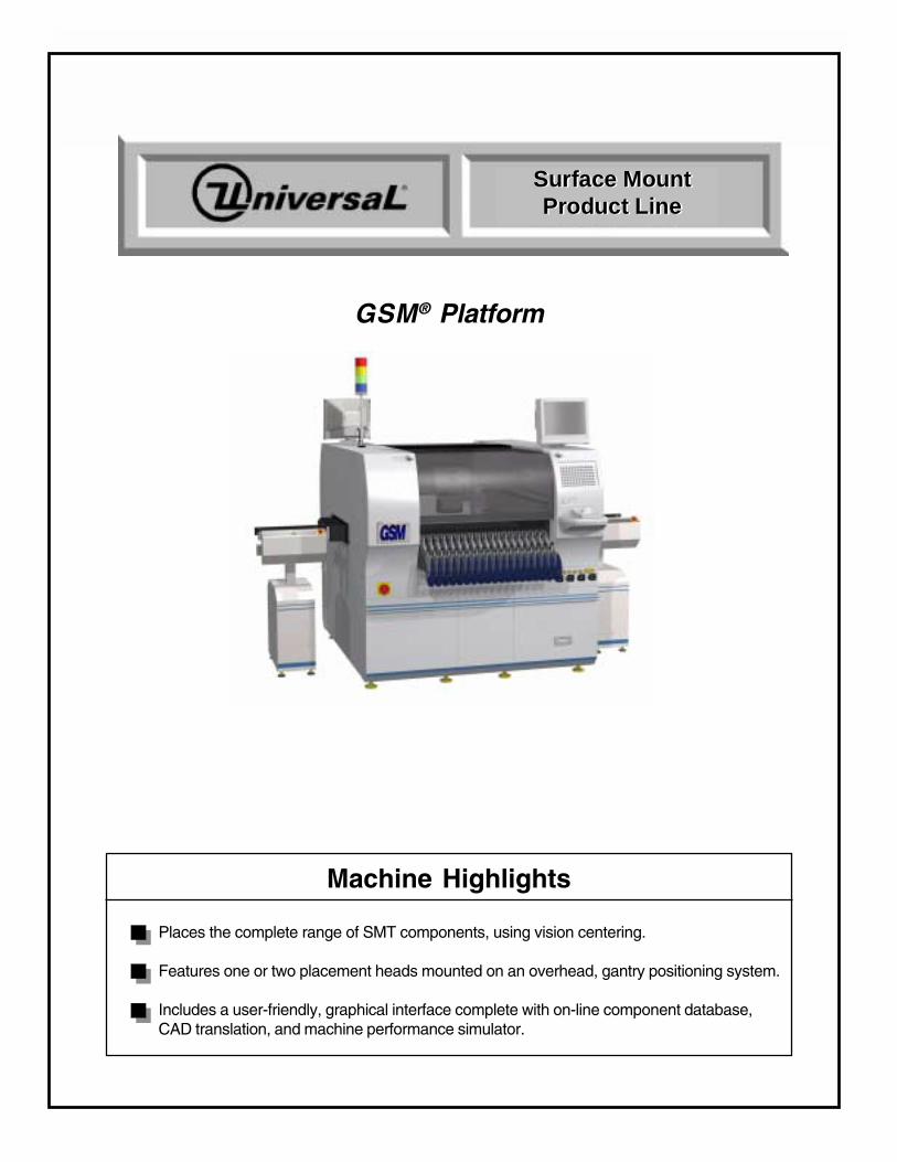
GSM® Platform
Places the complete range of SMT components, using vision centering.
Features one or two placement heads mounted on an overhead, gantry positioning system.
Includes a user-friendly, graphical interface complete with on-line component database,CAD translation, and machine performance simulator.
Machine Highlights
Surface MountProduct Line
Surface MountProduct Line
GS-401-01 BGSM Platform
Contents
Introduction ............................................................................................................... 1Functional Description ............................................................................................. 1Standard Features ..................................................................................................... 2
Base Frame ................................................................................................... 2Positioning System ........................................................................................ 2Staged Board Handling ................................................................................... 2Vision On-the-Fly ........................................................................................... 2Nozzle Changing ............................................................................................ 2Fiducial Inspection ......................................................................................... 3Multi-Pattern Find ........................................................................................... 3Machine Control System Architecture ............................................................ 3Inspection Cameras ....................................................................................... 4Board Support ................................................................................................ 4
Universal Platform Software (UPS) ....................................................................... 5Off-Line PC Requirements ........................................................................................ 6Optional Features ...................................................................................................... 7
Component Shuttle ......................................................................................... 7Gripper Nozzles ............................................................................................. 7Feeders .......................................................................................................... 7Feeder Bank Changing ................................................................................... 8Feeder Setup Cart .......................................................................................... 8Feeder Storage Cart ....................................................................................... 8Removable Feeder Bank Storage Table ......................................................... 8Feeder Input ................................................................................................... 9
Board Handling ..................................................................................................... 9Applied Conveyor Engineering™ Conveyors................................................... 9Dual Lane Board Handling .............................................................................. 9Dual SMEMA ................................................................................................. 9
Heads ................................................................................................................. 10FlexJet® Head (GSM1 and/or GSM2) .......................................................... 10High Force Head (GSM1 and/or GSM2) ....................................................... 10Flex Head (GSM1 and/or GSM2) .................................................................. 10Archimedes Metering Valve (GSM1 only) ..................................................... 11Positive Displacement Pumo (GSM1 only) ................................................... 11UFP300+ Head (GSM1 only) ........................................................................ 11
Vision/Inspection ................................................................................................ 12FlexJet On-the-Head-Camera ....................................................................... 12Standard Upward Looking Camera................................................................ 12Circular Lighting Upward Looking Camera ..................................................... 13On-Axis Lighting Upward Looking Camera .................................................... 13Odd Form Upward Looking Camera .............................................................. 13Standard PEC (Pattern Error Correction) Downward Looking Camera ........... 14
Coplanarity ......................................................................................................... 15Coplanarity Specifications .................................................................................. 16Software Tools ................................................................................................... 17
Bar Code Product Changeover ..................................................................... 17GEM ............................................................................................................ 17Platform Setup Validation (PSV) .................................................................. 17Remote Diagnostics ..................................................................................... 17Line Level Software - Dimensions Manufacturing Automation Software Suite 18Dimensions Manufacturing Monitoring .......................................................... 18Dimensions Programming and Optimization ................................................. 18
GS-401-01 B GSM Platform
Contents
Electrical/Power Options .................................................................................... 19Transformer .................................................................................................. 19Uninterruptible Power Supply........................................................................ 19
Reject Stations ................................................................................................... 20Component Reject Station for components up to 50.8 mm square ............... 20
Advanced Surface Mount and Semiconductor Assembly Options ....................... 20Supporting Documents ........................................................................................... 21
GSM1 and GSM Dispenser Platform Positioning System Specifications ............ 21GSM2 Platform Positioning System Specifications ............................................ 21Global and Local Fiducial Shapes and Dimensions ............................................. 22Recommended Fiducial and Bad Mark Sense..................................................... 22Board Specifications ........................................................................................... 23Board Clearance ................................................................................................. 23Board Handling ................................................................................................... 23Rear Rail Position Location ................................................................................. 24Optional Large Board Kit ..................................................................................... 25
Large Board Kit Limitations .......................................................................... 25Limitations for Board Lengths between 20" and 23" ...................................... 26Limitations for Board Lengths between 23" and 25" ...................................... 26
GSM Footprints: GSM1 ........................................................................................... 27GSM Footprints: GSM2 ........................................................................................... 28
Installation Considerations .................................................................................. 29Machine Dimensions .................................................................................... 29Service Requirements .................................................................................. 30Environmental Requirements........................................................................ 31
Appendix A: GSM Platform Feeders ................................................................... A-33Platform Tray Feeder (PTF), Model 4559A .......................................................... A-33
Introduction ..................................................................................................... A-34Functional Description ..................................................................................... A-34Optional Features ............................................................................................ A-35
Pre-Orient Head ........................................................................................ A-35Configurations ........................................................................................... A-36Available PTF Mounting Locations ............................................................ A-37
Standard Features ........................................................................................... A-38Pallets ....................................................................................................... A-38Tray Transport ........................................................................................... A-38Transfer Shuttle ........................................................................................ A-38
PTF Options .................................................................................................... A-39Orientation Tray Clamps............................................................................ A-39Side Discharge Kit .................................................................................... A-39Large Pocket Tray Removal Kit ................................................................. A-39Low Profile Scrap Bin ................................................................................ A-40Heavy Payload Kit .................................................................................... A-40PSV Barcode Kit ....................................................................................... A-40
Technical Specifications .................................................................................. A-41Configuration ............................................................................................. A-41Component Pick and Transfer Specifications ............................................ A-41Components .............................................................................................. A-42Matrix Tray ................................................................................................ A-42Pallets ....................................................................................................... A-43Magazine .................................................................................................. A-43
GS-401-01 BGSM Platform
Contents
Installation Considerations ........................................................................ A-44PTF Service Requirements ....................................................................... A-44PTF Conveyor Service Requirements ....................................................... A-44Environmental Requirements..................................................................... A-44
Supporting Documents .................................................................................... A-45Stackable Matrix Tray Feeder, Model 4556A ....................................................... A-46
Introduction ..................................................................................................... A-46Standard Features ........................................................................................... A-46Functional Description ..................................................................................... A-46Technical Specifications .................................................................................. A-47Service Requirements ..................................................................................... A-48
Multi-Pitch Tape Feeders, Model 4697A.............................................................. A-49Introduction ..................................................................................................... A-49Machine Concept ............................................................................................. A-49Standard Features ........................................................................................... A-49Functional Description ..................................................................................... A-50Supporting Documents .................................................................................... A-50
Technical Specifications for Multi-Pitch Tape Feeders ..................................... A-51Multi-Pitch Tape Feeder Pocket Depth and Length Limitations ........................ A-53Pneumatic Tape Feeders, Model 4695A .............................................................. A-54
Introduction ..................................................................................................... A-54Machine Concept ............................................................................................. A-54Standard Features ........................................................................................... A-54Functional Description ..................................................................................... A-55Supporting Documents .................................................................................... A-55
Technical Specifications for Pneumatic Tape Feeders ...................................... A-56Track Feeder, Model 4696A ................................................................................. A-58
Introduction ..................................................................................................... A-58Machine Concept ............................................................................................. A-58Standard Features ........................................................................................... A-58
Track Assembly ........................................................................................ A-58Feeder Base Assembly ............................................................................. A-58
Functional Description ..................................................................................... A-59Technical Specifications .................................................................................. A-59
Stationary Matrix Tray Platform, Model 4649A ................................................... A-60Introduction ..................................................................................................... A-60Functional Description ..................................................................................... A-60Technical Specifications .................................................................................. A-60Matrix Tray Pick Limitations ............................................................................ A-60
Multi-Tube Feeders, Model 4698A ....................................................................... A-61Introduction ..................................................................................................... A-61Standard Features ........................................................................................... A-61Functional Description ..................................................................................... A-62Technical Specifications .................................................................................. A-62
Bulk Track Feeder, Model 4702A ......................................................................... A-63Introduction ..................................................................................................... A-63Machine Concept ............................................................................................. A-63Standard Features ........................................................................................... A-63Functional Description ..................................................................................... A-64Component Specifications ............................................................................... A-64Technical Specifications .................................................................................. A-64
GS-401-01 B GSM Platform
Appendix B: Placement Heads ............................................................................ B-65FlexJet Head ................................................................................................... B-66Flex Head and High Force Heads .................................................................... B-67GSM Platform: Placement Throughput Specifications ..................................... B-68UFP300+ Head (GSM1 only) ........................................................................... B-69Dispense Heads (GSM1 only) .......................................................................... B-70Archimedes Metering Valve ............................................................................. B-70Positive Displacement Pump ........................................................................... B-71Dispensing Nozzle Tooling Configurations ....................................................... B-72
Appendix C: Cameras .......................................................................................... C-73Technical Specifications ..................................................................................... C-73
Appendix D: Board Handling ............................................................................... D-75Dual Lane Board Handling .................................................................................. D-75
First In First Out (FIFO) Mode ................................................................... D-75Dynamic Mode .......................................................................................... D-75Technical Specifications ........................................................................... D-76Maximum Board Width Configuration ........................................................ D-76Dual Lane Board Handling ......................................................................... D-76
Appendix E: Odd Form Assembly Capabilities .................................................. E-77Introduction .......................................................................................................... E-77Applications ......................................................................................................... E-77
Components .................................................................................................... E-78Component Tolerances .................................................................................... E-80High Force Head .............................................................................................. E-80UFP 300+ Head (GSM1 only) .......................................................................... E-80Speed .............................................................................................................. E-81Vision-On-the-Fly ............................................................................................. E-81Odd-Form Feeders........................................................................................... E-81Cameras .......................................................................................................... E-81Passive Clinch Option ..................................................................................... E-81
Appendix F: GSM Platform Traceability ............................................................. F-83Bar Code Changeover Option .............................................................................. F-83
Introduction ..................................................................................................... F-83Restrictions/Limitations ................................................................................... F-83Bar Code Types ............................................................................................... F-84
Platform Setup Validation (PSV) Option............................................................. F-85Introduction ..................................................................................................... F-85PSV Specifications ......................................................................................... F-86PSV on PTF Assumption and Limitations ........................................................ F-86GEM Host Interface Driver .............................................................................. F-87Dimensions Manufacturing Monitoring ............................................................. F-87
GS-401-01 BGSM Platform
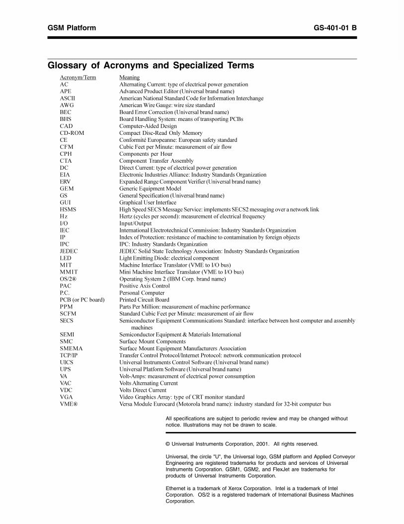
All specifications are subject to periodic review and may be changed withoutnotice. Illustrations may not be drawn to scale.
© Universal Instruments Corporation, 2001. All rights reserved.
Universal, the circle "U", the Universal logo, GSM platform and Applied ConveyorEngineering are registered trademarks for products and services of UniversalInstruments Corporation. GSM1, GSM2, and FlexJet are trademarks forproducts of Universal Instruments Corporation.
Ethernet is a trademark of Xerox Corporation. Intel is a trademark of IntelCorporation. OS/2 is a registered trademark of International Business MachinesCorporation.
���������� ��� ���� ������� ���������������������� �������������� ����� ������������������ ������� ��������������� �!�"" ��� ����#�� �����!����������������"������� ���"����$����%& ��� ����% ��&������ ��� '���������(�� (����������������� ������ ��������������� ()! (�����)���� ���!����������������������� �����(���* �������+� ���*� ���*+,-� ��������* ��+,���-����������� ������� �.����������������������������������/� ��� ��/������ ������������������ ��������) �������������)����� �����������������������*� * ����������������������� �������������� ���"� ������� ��"������ ����� �����"��������!���������-���� '�� ���,0 �1������,�������������0� � ����� ��������������� &�� &�� ���2� ���������&! &�����!�� � ��� ������ ��������������� &�" &���$ ��������"������)!�! ) �$�!���!��!�������!�� ��� ��������!��!3������ ��������������4�� �4)' )��'���������������� ������������������ ������2����"�- "�����-�����"�� "������ �������������$� �������� �� ����"��������!���������-���� '�� ��"� "��1���������� ������ ������������$ ����������� ��� ��������� �����5���"�� "����"��������!���������-���� '�� ��6�*�� 6�*���!�� ��!�����$������������ �� ����"��������!���������-���� '�� ��7�* 7 �$���� �� ���* �������� �������������" ���$ ��"������������������0������"�-���� ��" � � ����$ ��"������������������0������"�-���� -!�38 -���� ���!�����3��"(������9���������� ��� ��� � ���1 ����������9�9 �����������������(������������� �� ����� ��� ��(������� ���������� �� �������������������$ �����������!�/� !����������� ��/������ ������������������ ������!��! !� �����������2� ����������� ��� ����!��������� ������������$�����������������������
���$ ��!��" !� �����������2� �����:����� ����"������ ����!�� !���������������������!���� !�������������2� ����������������������� �� �����"� ������������������������"���������������������4������� ��� ������������"�! �� ������"������������������!���������� ��������������� ��! �� ���������������!���������� ��������������� 0� 0���+���������������������� ����������������� ��0�� 0������������ ���������0*� 0�����* ����������0&� 0 ���&���$ ������������������,���� ������������0��8 0�������������������������������������� �� ���������������������;3+� �������������
Glossary of Acronyms and Specialized Terms
Page 1GS-401-01 B
GS
M P
latfo
rm S
tand
ard
and
Opt
iona
l F
eatu
res
Introduction
����������� ��������������������������������������������������������������������������������������������������������������������������������������������������������� ����������������������������� �������������������������������������������������
�����������������������������������������������!��������������� �������������"#����$���� ���������#""�"�������%���
Functional Description
&������������������� ����������'� �()���������������������������$������������������������������������������������������������������������������������� ���*�������� ����������������������������������������������������������������������
&����������������� ����������'� �+)��������������������������$�������������������������������������������*��������������������������������������������������������������������������������������������������������$,�����������������������������������������������������������������������������������������������������������������������$��*����������������������������������������������������������������������-�������������������������������������������������������$����������������� ���*�������� ������������������������������������������������������������������������
Page 2 GS-401-01 B
GS
M P
latfo
rm S
tand
ard
and
Opt
iona
l F
eatu
res
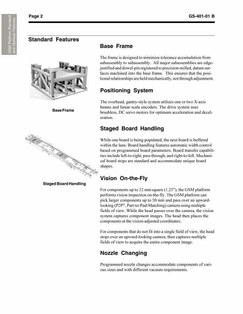
Base Frame
Vision On-the-Fly
&��������������������.+�����!�����'(�+/0)������� �����������������������������������������������*���� ����������������$������������������������/1������������������������������$����'2+2���2�������2�����������)�����������������������������������-���������������������������������������������������������������������������������*�������������������������������������������������3������������������
&����������������������������������������������������������������������������������������$���������������������������������������������������!��������������������������������
Nozzle Changing
2������������44�����������������������������������������������4�������������������������������!����������
Staged Board Handling
Standard FeaturesBase Frame
*������������������������������4������������������������������������������������������5���3�������������������������3���������������������������������������������������������������������������������������������������*�������������������������������������������������������������������������������3��������
Positioning System
*������������������������������������4��������������6������������������������������������*������������������������������7"�������������������������������������������������������
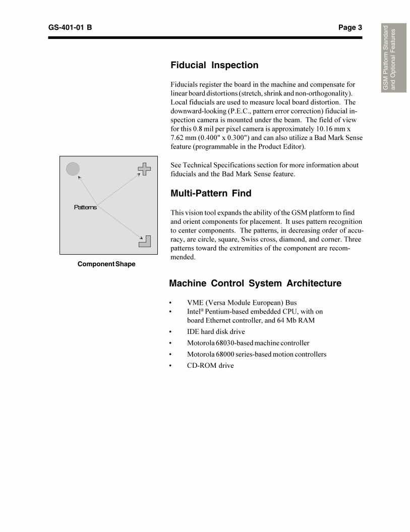
Staged Board Handling
-���������������������������������������������������������������������������8����������������������������������������������������������������������������������8���������������������������������������������������������������������������������������������������������������������������������������!���������������
Page 3GS-401-01 B
GS
M P
latfo
rm S
tand
ard
and
Opt
iona
l F
eatu
res
Machine Control System Architecture
9 :�#�':�����������#�������)�8��9 �����2����������������������"2����������
������#����������������������;<����=5�
9 7#���������$������
9 ��������;>1.1�����������������������
9 ��������;>111������������������������������
9 "7�=?�������
Component Shape
Patterns
Fiducial Inspection
&������������������������������������������������������������������������������������'��������������$���������������������)�@��������������������������������������������������������*�������������$����'2�#�"���������������������������)��������������������������������������������������������*������������������������1�>������������������������������������(1�(;�����A�;+����'1�<110���1�.110)�����������������4����8������$� ������������'�������������������2�������#�����)�
���*�������� �����������������������������������������������������������������8������$� �������������
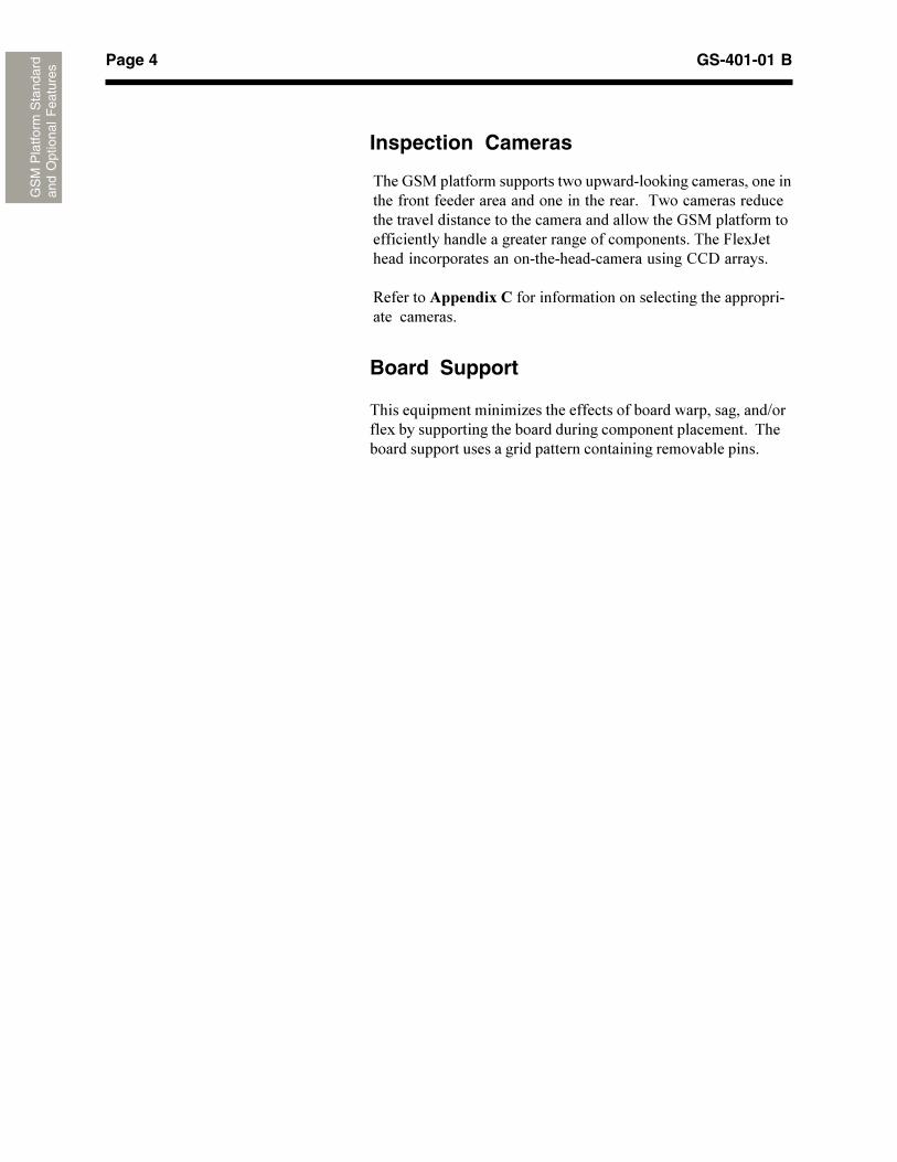
Multi-Pattern Find
*������������������������������������������ ������������������������������������������������������ �������������������������������������������������*�����������������������������������������������������������!������ ���������������������������������*����������������������������������������������������������������������
Page 4 GS-401-01 B
GS
M P
latfo
rm S
tand
ard
and
Opt
iona
l F
eatu
res
Board Support
*�����!��������������4��������������������������������������B����������������������������������������������������������*�������������������������������������������������������������
Inspection Cameras
*���� ��������������������������������$���������������������������������������������������������������*��������������������������������������������������������������� ������������������������������������������������������������*���&��C������������������������������������������������""7��������
=��������������������������������������������������������������� ��������
Page 5GS-401-01 B
GS
M P
latfo
rm S
tand
ard
and
Opt
iona
l F
eatu
res
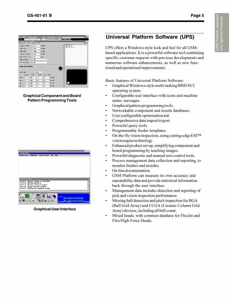
Universal Platform Software (UPS)
8��������������������������2������� �������D9 ���������-��������������������$���� 8��? B+
�����������������9 "������������������������������������������������
������� ���������9 ����������������������������������9 E�����$��������������������44������������9 �����������������������4����������9 "������������������������B�������9 2�������!����������9 2���������������������������9 ?�����������������������������������������������# F
������������������������9 #������������������������������������������������
�������������������������������������9 2���������������������������������������������9 2�������������������������������������������������
����������������������44���9 ?��������������������9 � ��2���������������������������������������
�������������������������������������������������������$����������������������������
9 �����������������������������������������������������$�����������������������������������
9 ����������������������������������������������8�5'8�������5����)�����""�5�'"�������"���������5����)������������������������������
9 ��������������������������������������&��C������&��BG����&�����G�����
�2 ����������-��������������$���������������� ��������������������� ���������������������������������������������������������!�����������������������������������������������������������������������������������������������������������������������
Graphical Component and BoardPattern Programming Tools
Graphical User Interface
Page 6 GS-401-01 B
GS
M P
latfo
rm S
tand
ard
and
Opt
iona
l F
eatu
res
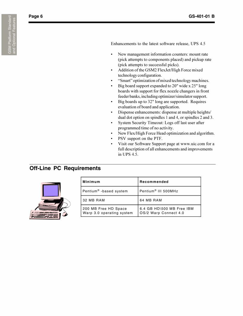
Off-Line PC Requirements
Minimum Recommended
Pentium® -based system Pentium® III 500MHz
32 MB RAM 64 MB RAM
200 MB Free HD SpaceWarp 3.0 operating system
6.4 GB HD\500 MB Free IBMOS/2 Warp Connect 4.0
#�������������������������������������������2 �<�/
9 E����������������������������������D�����������'���$�����������������������������)��������$�������'���$��������������������������$�)�
9 5���������������� �+�&��C��BG����&����������������������������������
9 H ����I�������4����������������������������������9 8�����������������������������+10��������+/0����
������������������������������44�����������������������������$������������������4��B�����������������
9 8����������������.+0���������������������=�!���������������������������������������
9 7��������������������D���������������������������B��������������������������(�����<�������������+�����.�
9 ������ ��������*������D�@�����������������������������������������������������
9 E���&��BG����&�����G����������4�������������������9 2 :����������������2*&�9 :��������� �������� ��������������������������������
�����������������������������������������������������2 �<�/�
Page 7GS-401-01 B
GS
M P
latfo
rm S
tand
ard
and
Opt
iona
l F
eatu
res
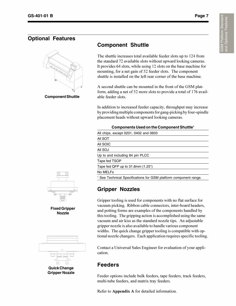
Component Shuttle
Optional FeaturesComponent Shuttle
*���������������������������������������������������(+<������������������A+�������������������������������$������������ �����������;<������������������(+���������������������������������������������������������/+���������������*�������������������������������������������������������������������������
5��������������������������������������������������� ����������������������������/+��������������������������������(A;����������������������
�����������������������������������������������������������������������������������������������������������$��������������������������������������������������$������������
Components Used on the Component Shuttle1
All chips, except 0201, 0402 and 0603
All SOT
All SOIC
All SOJ
Up to and including 84 pin PLCC
Tape fed TSOP
Tape fed QFP up to 31.8mm (1.25")
No MELFs1 See Technical Specifications for GSM platform component range.
Gripper Nozzles
�����������������������������������������������������������������������$������=������������������������������������������������������������������������������������������������������������������*���������������������������������������������������������������$����������������������44���������5����3����������������44����������������������������������������������������*���!���$����������������������������������������������������44�������������#�����������������!����������������������
"������������������ ����#������������������������������������������
Feeders
&�����������������������$����������������������������$����������������������������������������������������
=�������������������������������������������
Fixed GripperNozzle
Quick ChangeGripper Nozzle
Page 8 GS-401-01 B
GS
M P
latfo
rm S
tand
ard
and
Opt
iona
l F
eatu
res
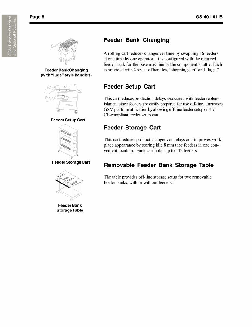
Feeder Storage Cart
Feeder BankStorage Table
Feeder Setup Cart
*�������������������������������������������������������������������������������������������������������������������������� ��������� ��������������4�������������������������������������������"#����������������������������
Feeder Storage Cart
*����������������������������������������������������������$��������������������������������>����������������������������������������������#��������������������(.+���������
Removable Feeder Bank Storage Table
*�����������������������������������������������������������������$���������������������������
Feeder Bank Changing
5������������������������������������������������(;�������������������������������������� ���������������������������!���������������$�����������������������������������������������#��������������������+������������������H�������������I�����H����IFeeder Bank Changing
(with “luge” style handles)
Feeder Setup Cart
Page 9GS-401-01 B
GS
M P
latfo
rm S
tand
ard
and
Opt
iona
l Fea
ture
s
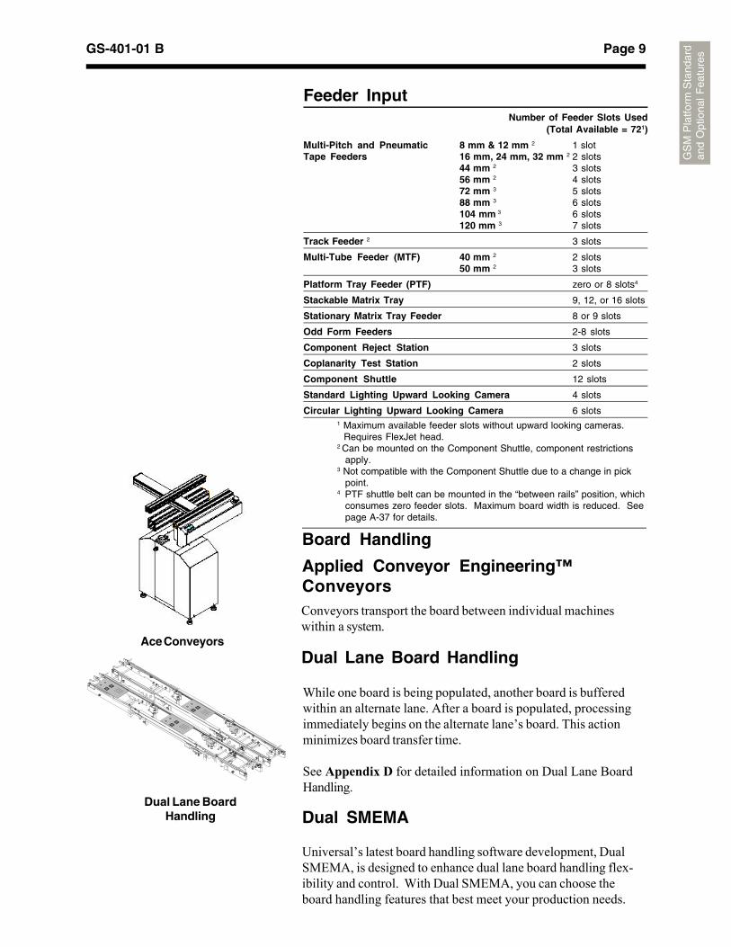
Dual SMEMA
Universal’s latest board handling software development, DualSMEMA, is designed to enhance dual lane board handling flex-ibility and control. With Dual SMEMA, you can choose theboard handling features that best meet your production needs.
Conveyors transport the board between individual machineswithin a system.
While one board is being populated, another board is bufferedwithin an alternate lane. After a board is populated, processingimmediately begins on the alternate lane’s board. This actionminimizes board transfer time.
See Appendix D for detailed information on Dual Lane BoardHandling.
Dual Lane Board Handling
Dual Lane BoardHandling
Board Handling
Applied Conveyor Engineering™Conveyors
Ace Conveyors
Feeder InputNumber of Feeder Slots Used
(Total Available = 721)
Multi-Pitch and Pneumatic 8 mm & 12 mm 2 1 slotTape Feeders 16 mm, 24 mm, 32 mm 2 2 slots
44 mm 2 3 slots56 mm 2 4 slots72 mm 3 5 slots88 mm 3 6 slots104 mm 3 6 slots120 mm 3 7 slots
Track Feeder 2 3 slots
Multi-Tube Feeder (MTF) 40 mm 2 2 slots50 mm 2 3 slots
Platform Tray Feeder (PTF) zero or 8 slots4
Stackable Matrix Tray 9, 12, or 16 slots
Stationary Matrix Tray Feeder 8 or 9 slots
Odd Form Feeders 2-8 slots
Component Reject Station 3 slots
Coplanarity Test Station 2 slots
Component Shuttle 12 slots
Standard Lighting Upward Looking Camera 4 slots
Circular Lighting Upward Looking Camera 6 slots1 Maximum available feeder slots without upward looking cameras. Requires FlexJet head.2 Can be mounted on the Component Shuttle, component restrictions
apply.3 Not compatible with the Component Shuttle due to a change in pick
point.4 PTF shuttle belt can be mounted in the “between rails” position, which
consumes zero feeder slots. Maximum board width is reduced. Seepage A-37 for details.
Page 10 GS-401-01 B
GS
M P
latfo
rm S
tand
ard
and
Opt
iona
l F
eatu
res
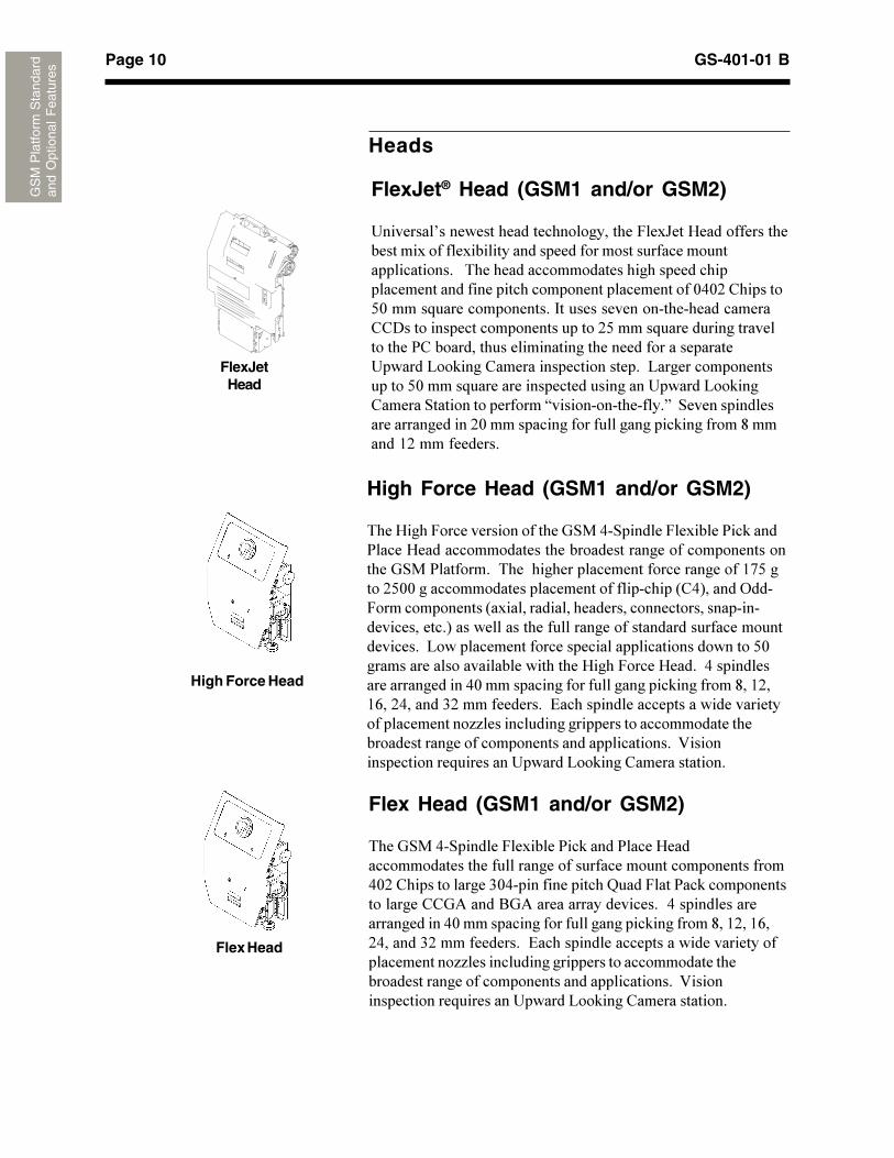
Heads
FlexJetHead
FlexJet® Head (GSM1 and/or GSM2)
��������J�����������������������������&��C���G�����������������������������������������������������������������������������������*����������������������������������������������������������������������������������1<1+�"�������/1�����!����������������� �������������������������������""7������������������������������+/�����!������������������������2"������������������������������������������������������@��$����"������������������������@����������������������/1�����!�����������������������������������@��$���"������ ������������������H�����������������I�� ����������������������������+1���������������������������$���������>�������(+������������
High Force Head (GSM1 and/or GSM2)
*���G����&��������������������� ��<� ������&������2��$����2����G��������������������������������������������������������� ��2���������*�����������������������������������(A/�����+/11�������������������������������������'"<)������?���&���������������'�������������������������������������������������������)����������������������������������������������������������@���������������������������������������������/1�������������������������������G����&�����G������<������������������������<1���������������������������$���������>��(+�(;��+<������.+��������������#�����������������������������������������������44��������������������������������������������������������������������������������������:������������������!����������������@��$����"��������������
Flex Head
High Force Head
Flex Head (GSM1 and/or GSM2)
*���� ��<� ������&������2��$�����2����G�������������������������������������������������������������<1+�"�������������.1<����������������K����&���2��$�������������������""�5�����8�5����������������������<������������������������<1���������������������������$���������>��(+��(;�+<������.+��������������#�����������������������������������������������44��������������������������������������������������������������������������������������:������������������!����������������@��$����"��������������
Page 11GS-401-01 B
GS
M P
latfo
rm S
tand
ard
and
Opt
iona
l F
eatu
res
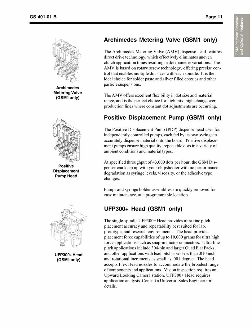
UFP300+ Head (GSM1 only)
*�����������������&2.11L�G�������������������������������������������������������������������������������������������������������������������������*����������������������������������������������������(1�111������������������������������������������������������������������������������������������������������������.1<���������������K����&���2��$�����������������������������������������4�������������1(1�����������������������������������������11(����������*���������������&���G������44��������������������������������������������������������������������:�������������������!���������������@��$����"����������������&2.11L�G������!�������������������������"����������������� ����#������������������
UFP300+ Head(GSM1 only)
Archimedes Metering Valve (GSM1 only)
*���5�������������������:����'5�:)���������������������������������������������������������������������������������������������������������������������������������������������*��5�:���������������������������������������������������������������������������������������4���������������������� ����������������������������������������������������������������������������������������
*���5�:�����������������������������������4����������������������������������������������������������������������������������������������������������������3�����������������������
Positive Displacement Pump (GSM1 only)
*���2��������7�����������2����'272)�������������������������������������������������������������������������������������������������������������������������������2���������������������������������������!��������������������������������������������������������������������������
5��������������������������<.�111��������������������� ��7��������������$��������������������������������������������������������������������������������������������������������������������
2�������������������������������������!���$��������������������������������������������������������
ArchimedesMetering Valve
(GSM1 only)
PositiveDisplacementPump Head
Page 12 GS-401-01 B
GS
M P
latfo
rm S
tand
ard
and
Opt
iona
l F
eatu
res
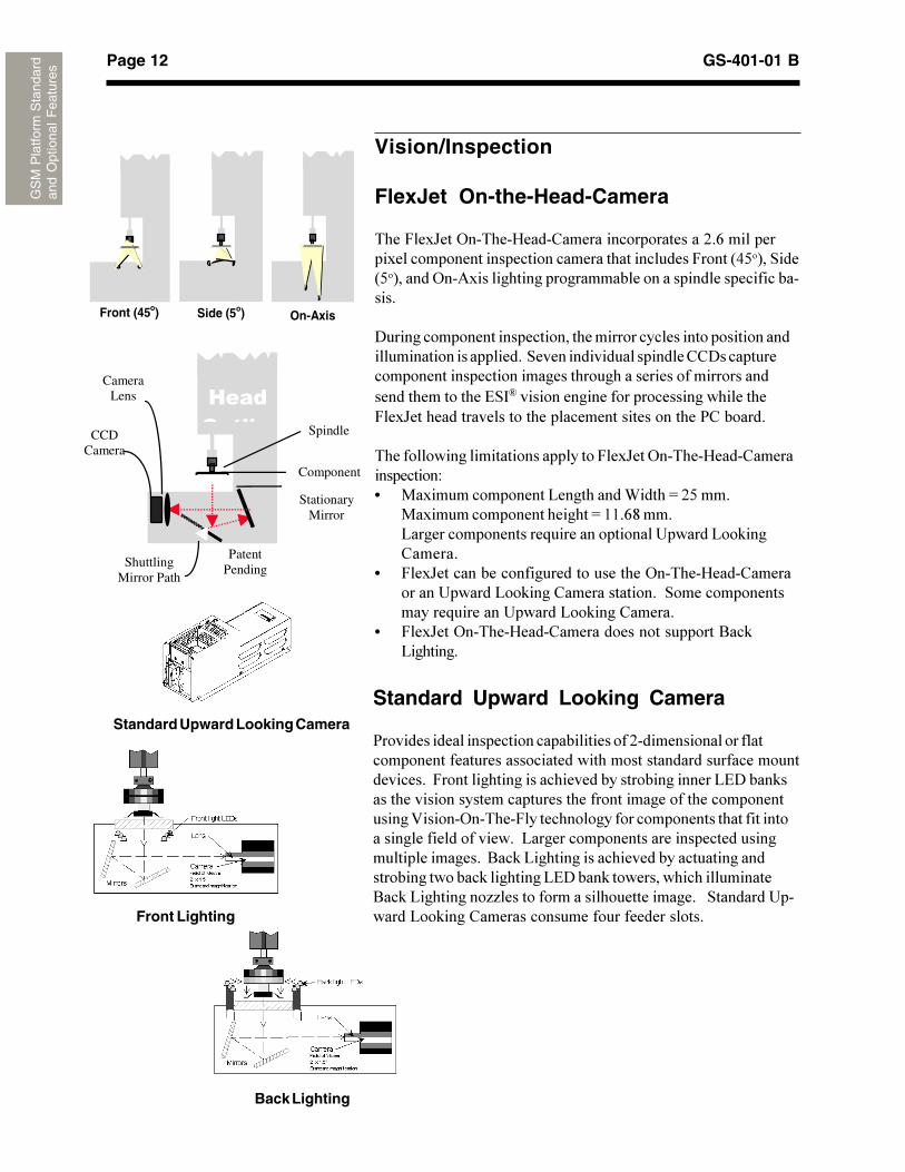
Vision/Inspection
FlexJet On-the-Head-Camera
*���&��C���?��*���G����"���������������������+�;�����������������������������������������������������&�����'</�)�� ���'/�)������?��5����������������������������������������������������
7������������������������������������������������������������������������������������� ����������������������""7�������������������������������������������������������������������������������������# ���������������������������������������&��C��������������������������������������������2"�������
*������������������������������&��C���?��*���G����"���������������D� ������������������@����������-�����M�+/����
�������������������������M�((�;>����@�������������������!�����������������������@��$���"������
� &��C��������������������������������?��*���G����"������������������@��$����"���������������� ��������������������!���������������@��$����"������
� &��C���?��*���G����"�����������������������8��$@��������
Standard Upward Looking Camera
2���������������������������������������+������������������������������������������������������������������������������������������&�������������������������������������������@#7����$���������������������������������������������������������������������:������?��*���&���������������������������������������������������������������@����������������������������������������������������8��$�@����������������������������������������������������$���������@#7����$�����������������������8��$�@����������44�������������������������������� ����������������@��$����"��������������������������������
Standard Upward Looking Camera
Front Lighting
Back Lighting
On-AxisSide (5o)Front (45o)
CCDCamera
����� �� Spindle
Component
StationaryMirror
CameraLens
ShuttlingMirror Path
PatentPending
Page 13GS-401-01 B
GS
M P
latfo
rm S
tand
ard
and
Opt
iona
l F
eatu
res
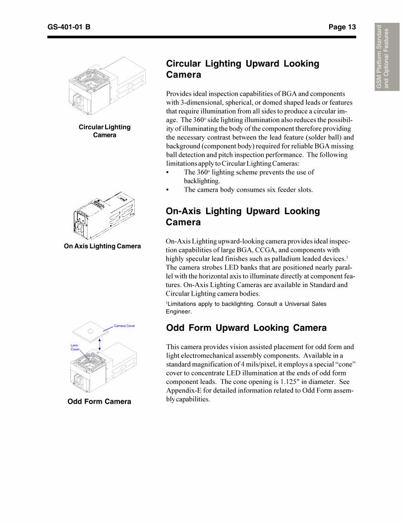
Circular Lighting Upward LookingCamera
2���������������������������������������8�5��������������������.��������������������������������������������������������������!�����������������������������������������������������������*���.;1����������������������������������������������������������������������������������������������������������������������������������������������������������������'��������)�������$�������'��������������)���!�����������������8�5��������������������������������������������������������*�����������������������������"�������@��������"������D� *���.;1������������������������������������
���$��������� *����������������������������������������
Circular LightingCamera
On-Axis Lighting Upward LookingCamera
?��5����@�����������������$���������������������������������������������������������8�5��""�5�������������������������������������������������������������������������������
*������������������@#7����$������������������������������������������������4������������������������������������������������������?��5����@��������"���������������������� �����������"�������@����������������������1Limitations apply to backlighting. Consult a Universal SalesEngineer.
Odd Form Upward Looking Camera
*�������������������������������������������������������������������������������������������������������5�������������������������������������<����B�������������������������H����I���������������������@#7����������������������������������������������������*�������������������(�(+/0��������������� ��5��������#�����������������������������������?���&�������������������������
LensCover
Camera Cover
Odd Form Camera
On Axis Lighting Camera
Page 14 GS-401-01 B
GS
M P
latfo
rm S
tand
ard
and
Opt
iona
l Fea
ture
s
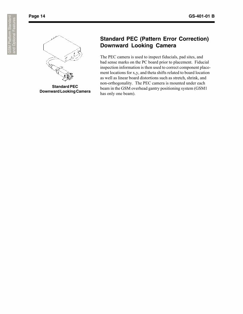
Standard PEC (Pattern Error Correction)Downward Looking Camera
The PEC camera is used to inspect fiducials, pad sites, andbad sense marks on the PC board prior to placement. Fiducialinspection information is then used to correct component place-ment locations for x,y, and theta shifts related to board locationas well as linear board distortions such as stretch, shrink, andnon-orthogonality. The PEC camera is mounted under eachbeam in the GSM overhead gantry positioning system (GSM1has only one beam).
Standard PECDownward Looking Camera
Page 15GS-401-01 B
GS
M P
latfo
rm S
tand
ard
and
Opt
iona
l F
eatu
res
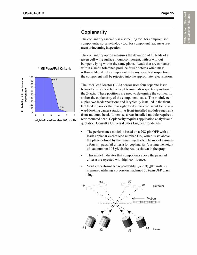
4 Mil Pass/Fail Criteria
7.8
98.5
0102030405060708090
100
1 2 3 4 5 6
Height of Lead Number 105 in mils
Pro
bab
ility
of
Acc
epta
nce
in
Per
cen
tag
e
#1
#1
#2
#2 #3
#3#4
#4
Detector
Motion
Laser
Coplanarity*���������������������������������������������������������������������������������������������������������������������������������������������
*�����������������������������������������������������������������������������������������������������������������������������������������������������@������������������������������������������������������������������������������������������ ������������������������������������������������������������������3�����������������������������3������������
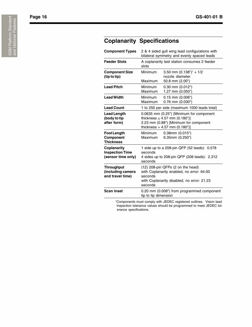
*�������������������'@@@)����������������������������������������������������������������������������������������������������N��������*������������������������������������������������������B������������������������������������������*�����������������������������������������������������������������������������������������$�����������������������������$����3�����������������������$���������������������5�����������������������!����������������������������@�$������������������������������!��������������������������"������������!����������������������������!����������"����������������� ����#�������������������
9 *����������������������������������+1>�����K&2��������������������������������������(1/������������������������������������������������������������*�����������������������������B�����������������������������:�������������������������������(1/�������������������������������������
9 *�������������������������������������������������B������������������3���������������������������
9 :���������������������������������O'����σ)�P1�;����Q����������������4�������������������������+1>�����K&2���������
Page 16 GS-401-01 B
GS
M P
latfo
rm S
tand
ard
and
Opt
iona
l F
eatu
res
Coplanarity Specifications
Component Types 2 & 4 sided gull wing lead configurations withbilateral symmetry and evenly spaced leads
Feeder Slots A coplanarity test station consumes 2 feederslots
Component Size Minimum 3.50 mm (0.138")1 + 1/2(tip to tip) nozzle diameter
Maximum 50.8 mm (2.00")
Lead Pitch Minimum 0.30 mm (0.012")Maximum 1.27 mm (0.050")
Lead Width Minimum 0.15 mm (0.006")Maximum 0.76 mm (0.030")
Lead Count 1 to 250 per side (maximum 1000 leads total)
Lead Length 0.0635 mm (0.25") [Minimum for component(body to tip thickness < 4.57 mm (0.180")]after form) 2.23 mm (0.88") [Minimum for component
thickness > 4.57 mm (0.180")]
Foot Length Minimum 0.38mm (0.015")Component Maximum 6.35mm (0.250")Thickness
Coplanarity 1 side up to a 208-pin QFP (52 leads): 0.578Inspection Time seconds(sensor time only) 4 sides up to 208-pin QFP (208 leads): 2.312
seconds
Throughput (12) 208-pin QFPs (2 on the head)(including camera with Coplanarity enabled, no error: 64.00and travel time) seconds
with Coplanarity disabled, no error: 21.23seconds
Scan Inset 0.20 mm (0.008") from programmed componenttip to tip dimension
1Components must comply with JEDEC registered outlines. Vision lead inspection tolerance values should be programmed to meet JEDEC tol- erance specifications.
Page 17GS-401-01 B
GS
M P
latfo
rm S
tand
ard
and
Opt
iona
l F
eatu
res
Bar Code Product Changeover
The Bar Code Product Changeover option allows for seamlessproduct changeover without requiring the user to manually loadthe product data or press the start button.
See Appendix F for more information about Bar Code ProductChangeover.
Software Tools
GEM
The Generic Equipment Model (GEM) software driver coupledwith a host software application such as Dimensions™ Manu-facturing Monitoring, provides a set of communication, data col-lection, command, and control tools for GSM platforms. Basedon the Semiconductor Equipment and Materials Internationalstandard, SEMI E30-93, this software driver opens the systemarchitecture for integration into factory data collection and auto-mation systems.
Platform Setup Validation (PSV)
This feature ensures correct component-to-feeder slot relation-ship for tape feeders with an integrated bar code validation pro-cess, which provides component level tracking through a historyfile.
See Appendix F for more information on PSV.
Remote Diagnostics
Remote diagnostics allows Universal support personnel to viewUPS (Universal Platform Software) screens, transfer files, andinterpret diagnostic messages from company headquarters inBinghamton, New York, USA. This feature provides an en-hanced level of technical support and decreases service andtrouble-shooting cycle times for GSM platforms.
Page 18 GS-401-01 B
GS
M P
latfo
rm S
tand
ard
and
Opt
iona
l Fea
ture
s
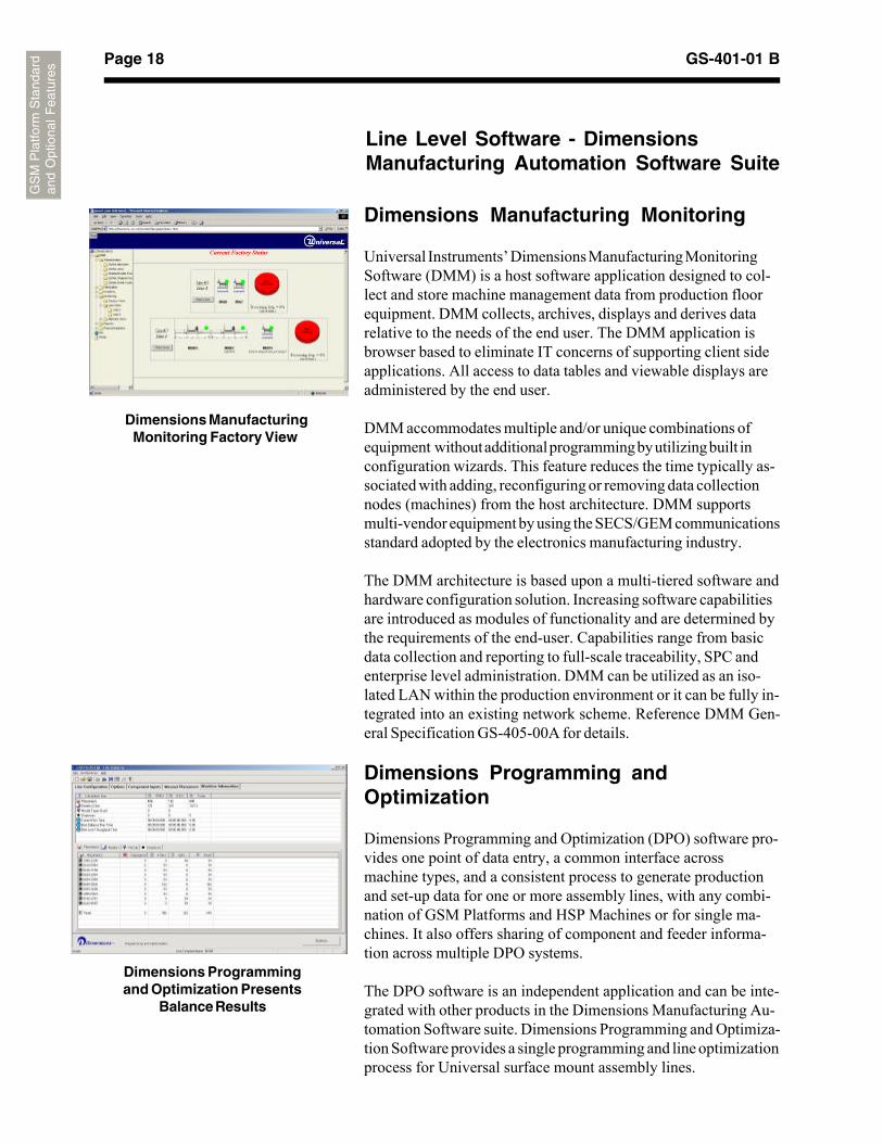
Dimensions Manufacturing Monitoring
Universal Instruments’ Dimensions Manufacturing MonitoringSoftware (DMM) is a host software application designed to col-lect and store machine management data from production floorequipment. DMM collects, archives, displays and derives datarelative to the needs of the end user. The DMM application isbrowser based to eliminate IT concerns of supporting client sideapplications. All access to data tables and viewable displays areadministered by the end user.
DMM accommodates multiple and/or unique combinations ofequipment without additional programming by utilizing built inconfiguration wizards. This feature reduces the time typically as-sociated with adding, reconfiguring or removing data collectionnodes (machines) from the host architecture. DMM supportsmulti-vendor equipment by using the SECS/GEM communicationsstandard adopted by the electronics manufacturing industry.
The DMM architecture is based upon a multi-tiered software andhardware configuration solution. Increasing software capabilitiesare introduced as modules of functionality and are determined bythe requirements of the end-user. Capabilities range from basicdata collection and reporting to full-scale traceability, SPC andenterprise level administration. DMM can be utilized as an iso-lated LAN within the production environment or it can be fully in-tegrated into an existing network scheme. Reference DMM Gen-eral Specification GS-405-00A for details.
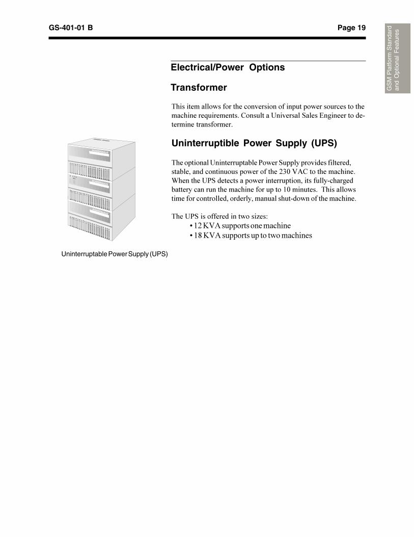
Dimensions Programming andOptimization
Dimensions Programming and Optimization (DPO) software pro-vides one point of data entry, a common interface acrossmachine types, and a consistent process to generate productionand set-up data for one or more assembly lines, with any combi-nation of GSM Platforms and HSP Machines or for single ma-chines. It also offers sharing of component and feeder informa-tion across multiple DPO systems.
The DPO software is an independent application and can be inte-grated with other products in the Dimensions Manufacturing Au-tomation Software suite. Dimensions Programming and Optimiza-tion Software provides a single programming and line optimizationprocess for Universal surface mount assembly lines.
Line Level Software - DimensionsManufacturing Automation Software Suite
Dimensions ManufacturingMonitoring Factory View
Dimensions Programmingand Optimization Presents
Balance Results
Page 19GS-401-01 B
GS
M P
latfo
rm S
tand
ard
and
Opt
iona
l F
eatu
res
Transformer
*������������������������������������������������������������������������!�����������"����������������� ����#����������������������������������
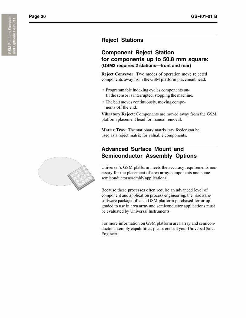
Uninterruptible Power Supply (UPS)
*��������������������������2����� ���������������������������������������������������������+.1�:5"����������������-���������2 ������������������������������������������������������������������������������������(1�����������*������������������������������������������������������������������
*����2 ���������������������4��D������������ ������������������������� ��� �� �����������
Electrical/Power Options
Uninterruptable Power Supply (UPS)
Page 20 GS-401-01 B
GS
M P
latfo
rm S
tand
ard
and
Opt
iona
l F
eatu
res
���������������*�����������������������������3������������������������������� �����������������������D
9��2��������������������������������������������������������������������������������������������
9��*������������������������������������������������������������
���������� �������"����������������������������������� ����������������������������������������
�������������*���������������������������������������������������3���������������������������������
Advanced Surface Mount andSemiconductor Assembly Options
��������J��� �������������������������������!���������������������������������������������������������������������������������������������������������
8�������������������������������!���������������������������������������������������������������������������������B������������$������������� �������������������������������������������������������������������������������������������������������������������� �����������
&������������������������ ���������������������������������������������������������������������������������������� ���#��������
Reject Stations
Component Reject Stationfor components up to 50.8 mm square:(GSM2 requires 2 stations—front and rear)
Page 21GS-401-01 B
GS
M P
latfo
rm S
tand
ard
and
Opt
iona
l F
eatu
res
Supporting Documents��������� � � ��2�������&��������������� � 2�������� G������������� "��������������� 8�����G��������������� � ?���&����5����������������� � � ��2�������*������������ ������������2�������"������������ �������������#!���������������������
5����������
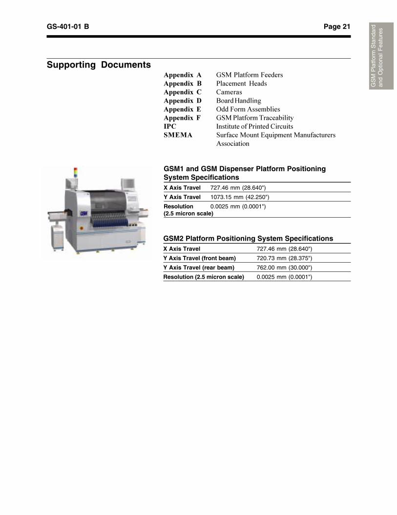
GSM1 and GSM Dispenser Platform PositioningSystem SpecificationsX Axis Travel 727.46 mm (28.640")
Y Axis Travel 1073.15 mm (42.250")
Resolution 0.0025 mm (0.0001")(2.5 micron scale)
GSM2 Platform Positioning System SpecificationsX Axis Travel 727.46 mm (28.640")
Y Axis Travel (front beam) 720.73 mm (28.375")
Y Axis Travel (rear beam) 762.00 mm (30.000")
Resolution (2.5 micron scale) 0.0025 mm (0.0001")
Page 22 GS-401-01 B
GS
M P
latfo
rm S
tand
ard
and
Opt
iona
l F
eatu
res
D1
D2
D1
D2
D1
D2
D1
D1
D2
D1
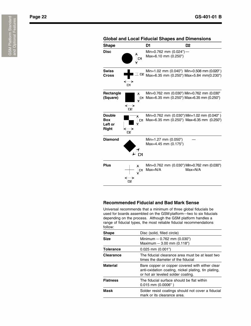
Global and Local Fiducial Shapes and DimensionsShape D1 D2Disc Min=0.762 mm (0.024") —
Max=6.10 mm (0.250")
Swiss Min=1.02 mm (0.040") Min=0.508 mm (0.020" )Cross Max=6.35 mm (0.250") Max=5.84 mm(0.230")
Rectangle Min=0.762 mm (0.030") Min=0.762 mm (0.030"(Square) Max=6.35 mm (0.250") Max=6.35 mm (0.250")
Double Min=0.762 mm (0.030") Min=1.02 mm (0.040" )Box Max=6.35 mm (0.250") Max=6.35 mm (0.250")Left orRight
Diamond Min=1.27 mm (0.050") —Max=4.45 mm (0.175")
Plus Min=0.762 mm (0.030") Min=0.762 mm (0.030")Max=N/A Max=N/A
Recommended Fiducial and Bad Mark SenseUniversal recommends that a minimum of three global fiducials beused for boards assembled on the GSM platform—two to six fiducialsdepending on the process. Although the GSM platform handles arange of fiducial types, the most reliable fiducial recommendationsfollow:
Shape Disc (solid, filled circle)
Size Minimum -- 0.762 mm (0.030")Maximum -- 3.00 mm (0.118")
Tolerance 0.025 mm (0.001")
Clearance The fiducial clearance area must be at least twotimes the diameter of the fiducial
Material Bare copper or copper covered with either clearanti-oxidation coating, nickel plating, tin plating,or hot air leveled solder coating.
Flatness The fiducial surface should be flat within0.015 mm (0.0006" )
Mask Solder resist coatings should not cover a fiducialmark or its clearance area.
Page 23GS-401-01 B
GS
M P
latfo
rm S
tand
ard
and
Opt
iona
l F
eatu
res
Board SpecificationsMinimum Maximum
Length 50.8 mm (2.00") 635.0 mm (25.00")1
Width 50.8 mm (2.00")2 508.0 mm (20.00")3
Thickness 0.508 mm (0.020") 5.08 mm (0.200")
Weight — 2.72 kg (6 pounds)4
Allowable Warp For board transfer: 5.537 mm (0.218") minusboard thickness
For placement: 0.75% of board length(as per IPC-2221), notto exceed 3.175 mm(0.125") total
1 Standard tooling accomodates board length up to 508.0 mm (20"). Anoptional large board kit increases maximum board length to 635.0 mm(25"). Limitations apply. Special applications are available for boards up to812.8 mm (32") x 508.0 mm (20"). Consult a Universal Sales Engineer fordetails.2 The component reject bin must be relocated and one mechanical boardstop must be removed to accomodate board width between 50.8 mm (2")and 88.9 mm (3.5"). Software reconfiguration is required.3 A maximum board width of 457.2 mm (18.00") includes nozzle changersmounted between the rear feeder plate and the staged board handlingsystem. An optional large board kit increases max width to 508.0 mm(20"). Limitations apply. See large board kit specs for details.4 Represents the sum of all board weights within the GSM platform boardhandling system and components placed.
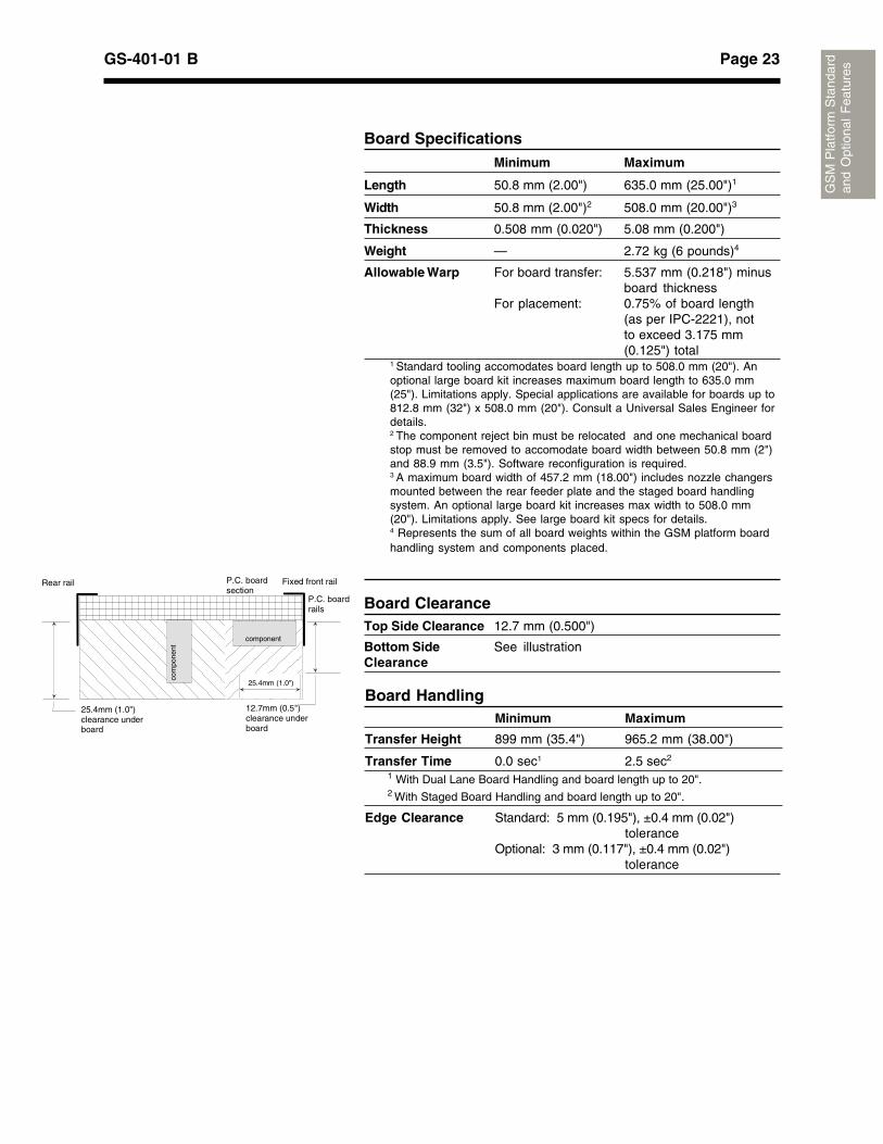
Board ClearanceTop Side Clearance 12.7 mm (0.500")
Bottom Side See illustrationClearance
Board HandlingMinimum Maximum
Transfer Height 899 mm (35.4") 965.2 mm (38.00")
Transfer Time 0.0 sec1 2.5 sec2
1 With Dual Lane Board Handling and board length up to 20".2 With Staged Board Handling and board length up to 20".
25.4mm (1.0")
12.7mm (0.5")clearance underboard
Fixed front railRear rail P.C. boardsection
P.C. boardrails
component
com
pone
nt
25.4mm (1.0")clearance underboard
Edge Clearance Standard: 5 mm (0.195"), ±0.4 mm (0.02")tolerance
Optional: 3 mm (0.117"), ±0.4 mm (0.02")tolerance
Page 24 GS-401-01 B
GS
M P
latfo
rm S
tand
ard
and
Opt
iona
l F
eatu
res
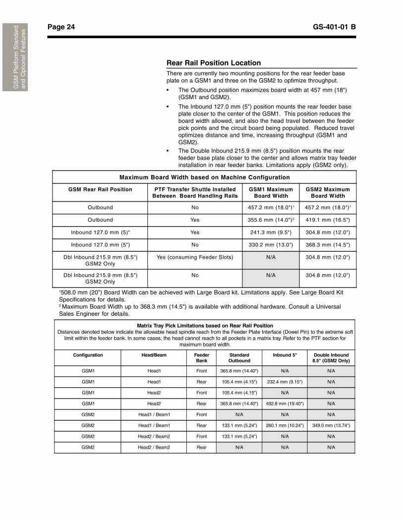
Rear Rail Position LocationThere are currently two mounting positions for the rear feeder baseplate on a GSM1 and three on the GSM2 to optimize throughput.
• The Outbound position maximizes board width at 457 mm (18")(GSM1 and GSM2).
• The Inbound 127.0 mm (5") position mounts the rear feeder baseplate closer to the center of the GSM1. This position reduces theboard width allowed, and also the head travel between the feederpick points and the circuit board being populated. Reduced traveloptimizes distance and time, increasing throughput (GSM1 andGSM2).
• The Double Inbound 215.9 mm (8.5") position mounts the rearfeeder base plate closer to the center and allows matrix tray feederinstallation in rear feeder banks. Limitations apply (GSM2 only).
Matrix Tray Pick Limitations based on Rear Rail PositionDistances denoted below indicate the allowable head spindle reach from the Feeder Plate Interface (Dowel Pin) to the extreme soft
limit within the feeder bank. In some cases, the head cannot reach to all pockets in a matrix tray. Refer to the PTF section formaximum board width.
Configuration Head/Beam FeederBank
StandardOutbound
Inbound 5" Double Inbound8.5" (GSM2 Only)
GSM1 Head1 Front 365.8 mm (14.40") N/A N/A
GSM1 Head1 Rear 105.4 mm (4.15") 232.4 mm (9.15") N/A
GSM1 Head2 Front 105.4 mm (4.15") N/A N/A
GSM1 Head2 Rear 365.8 mm (14.40") 492.8 mm (19.40") N/A
GSM2 Head1 / Beam1 Front N/A N/A N/A
GSM2 Head1 / Beam1 Rear 133.1 mm (5.24") 260.1 mm (10.24") 349.0 mm (13.74")
GSM2 Head2 / Beam2 Front 133.1 mm (5.24") N/A N/A
GSM2 Head2 / Beam2 Rear N/A N/A N/A
Maximum Board Width based on Machine Configuration
GSM Rear Rail Position PTF Transfer Shuttle InstalledBetween Board Handling Rails
GSM1 MaximumBoard Width
GSM2 MaximumBoard Width
Outbound No 457.2 mm (18.0")1 457.2 mm (18.0")1
Outbound Yes 355.6 mm (14.0")2 419.1 mm (16.5")
Inbound 127.0 mm (5)" Yes 241.3 mm (9.5") 304.8 mm (12.0")
Inbound 127.0 mm (5") No 330.2 mm (13.0") 368.3 mm (14.5")
Dbl Inbound 215.9 mm (8.5")GSM2 Only
Yes (consuming Feeder Slots) N/A 304.8 mm (12.0")
Dbl Inbound 215.9 mm (8.5")GSM2 Only
No N/A 304.8 mm (12.0")
1508.0 mm (20") Board Width can be achieved with Large Board kit. Limitations apply. See Large Board KitSpecifications for details.2 Maximum Board Width up to 368.3 mm (14.5") is available with additional hardware. Consult a UniversalSales Engineer for details.
Page 25GS-401-01 B
GS
M P
latfo
rm S
tand
ard
and
Opt
iona
l F
eatu
res
Large Board Kit Limitations:
9 5�����������������4������������������������������������;./�1����'+/0)������������*������������������������������������������������������������������������������������������
9 *��������������������������������/1>�1����'+10)����� �����@���� ������8�����G���������������������������������(��������������������������������������������������������� ������������
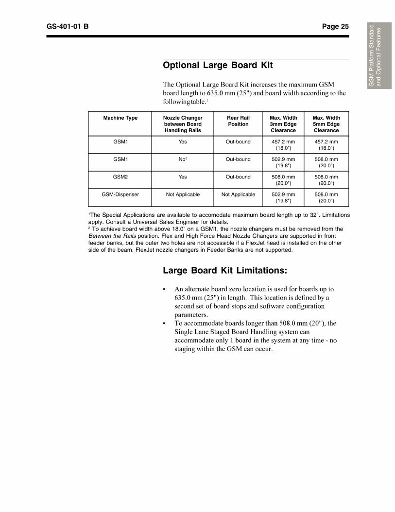
Optional Large Board Kit
*���?�������@�����8�����%�������������������������� ����������������;./�1����'+/0)�����������������������������������������������
Machine Type Nozzle Changerbetween BoardHandling Rails
Rear RailPosition
Max. Width3mm EdgeClearance
Max. Width5mm EdgeClearance
GSM1 Yes Out-bound 457.2 mm(18.0")
457.2 mm(18.0")
GSM1 No2 Out-bound 502.9 mm(19.8")
508.0 mm(20.0")
GSM2 Yes Out-bound 508.0 mm(20.0")
508.0 mm(20.0")
GSM-Dispenser Not Applicable Not Applicable 502.9 mm(19.8")
508.0 mm(20.0")
1The Special Applications are available to accomodate maximum board length up to 32". Limitationsapply. Consult a Universal Sales Engineer for details.2 To achieve board width above 18.0" on a GSM1, the nozzle changers must be removed from theBetween the Rails position. Flex and High Force Head Nozzle Changers are supported in frontfeeder banks, but the outer two holes are not accessible if a FlexJet head is installed on the otherside of the beam. FlexJet nozzle changers in Feeder Banks are not supported.
Page 26 GS-401-01 B
GS
M P
latfo
rm S
tand
ard
and
Opt
iona
l F
eatu
res
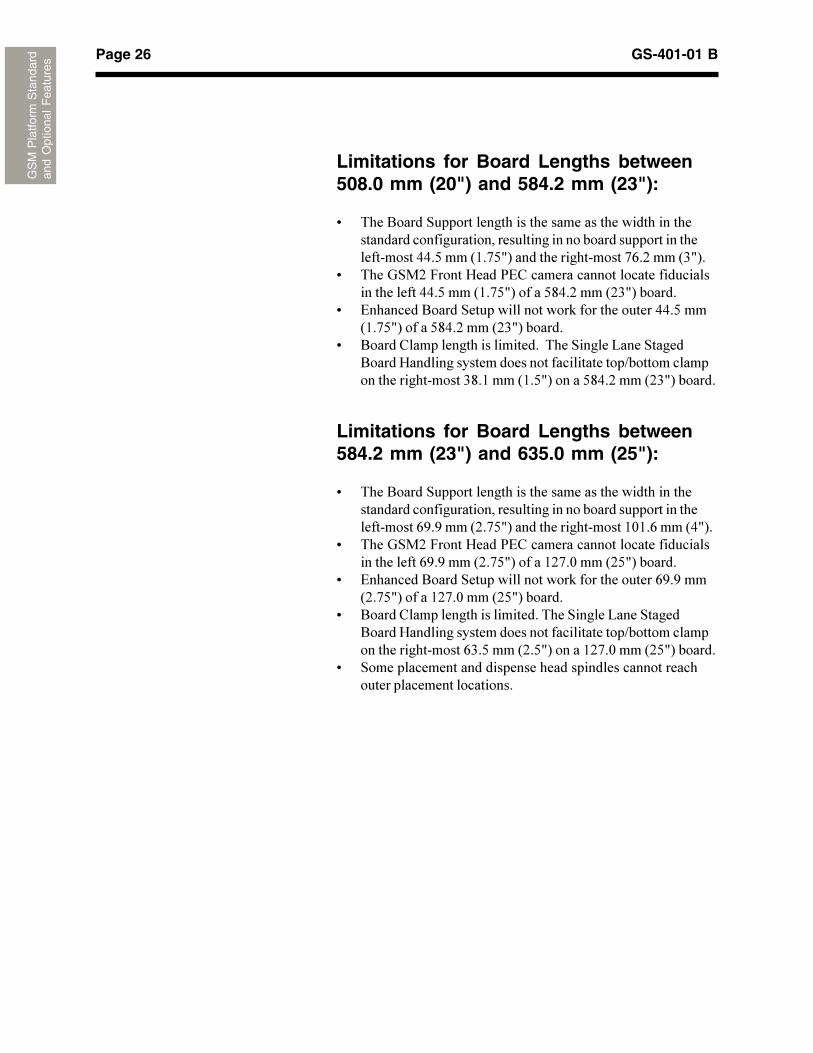
Limitations for Board Lengths between508.0 mm (20") and 584.2 mm (23"):
9 *���8����� ����������������������������������������������������������������������������������������������������������������<<�/����'(�A/0)��������������������A;�+����'.0)�
9 *���� �+�&�����G����2#"����������������������������������������<<�/����'(�A/0)������/><�+����'+.0)�������
9 #��������8����� ���������������$���������������<<�/���'(�A/0)������/><�+����'+.0)�������
9 8�����"����������������������*��� �����@���� �����8�����G������������������������������������B�����������������������������.>�(����'(�/0)������/><�+����'+.0)�������
Limitations for Board Lengths between584.2 mm (23") and 635.0 mm (25"):
9 *���8����� ����������������������������������������������������������������������������������������������������������������;R�R����'+�A/0)��������������������(1(�;����'<0)�
9 *���� �+�&�����G����2#"����������������������������������������;R�R����'+�A/0)������(+A�1����'+/0)�������
9 #��������8����� ���������������$���������������;R�R���'+�A/0)������(+A�1����'+/0)�������
9 8�����"���������������������*��� �����@���� �����8�����G������������������������������������B�����������������������������;.�/����'+�/0)������(+A�1����'+/0)�������
9 ���������������������������������������������������������������������������
Page 27GS-401-01 B
GS
M P
latfo
rm S
tand
ard
and
Opt
iona
l F
eatu
res
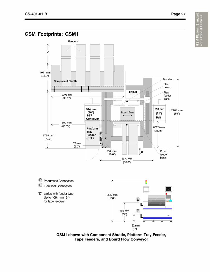
GSM1 shown with Component Shuttle, Platform Tray Feeder,Tape Feeders, and Board Flow Conveyor
GSM Footprints: GSM1
D
Board flow
GSM1
559 mm
(22")
Belt
1676 mm(66.0")
P
E
857.3 mm(33.75")
254 mm(10.0")
Rear beam
Rear feeder bank
Front feeder bank
Nozzles
Pneumatic Connection
Electrical Connection
"D" varies with feeder type: Up to 406 mm (16") for tape feeders
PE
686 mm(27")
152 mm(6")
2540 mm(100")
P
E
(70.0")
1041 mm(41.0")
D
Feeders
(63.35")
2305 mm(90.75")
Component Shuttle
914 mm (36") PTFConveyor
PlatformTray Feeder(PTF)
76 mm(3.0")
1778 mm
1609 mm
2184 mm(86")
Page 28 GS-401-01 B
GS
M P
latfo
rm S
tand
ard
and
Opt
iona
l F
eatu
res
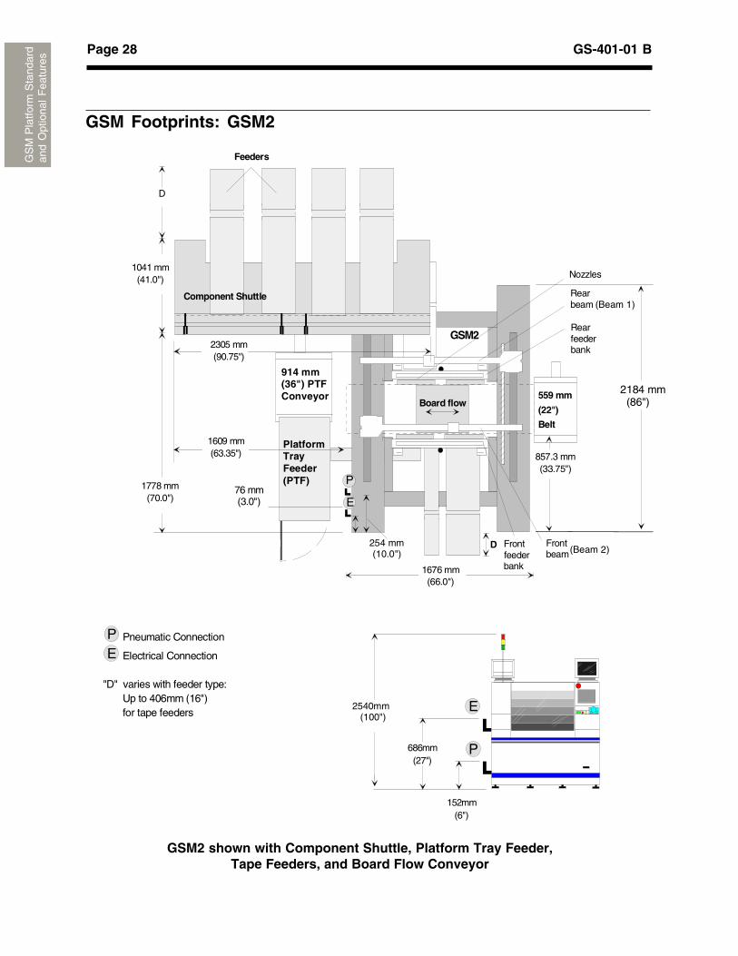
GSM2 shown with Component Shuttle, Platform Tray Feeder,Tape Feeders, and Board Flow Conveyor
D
Board flow
GSM2
559 mm
(22")
Belt
1676 mm(66.0")
P
E
857.3 mm(33.75")
254 mm(10.0")
Rear beam
Front beam
Rear feeder bank
Front feeder bank
Nozzles
914 mm(36") PTFConveyor
PlatformTray Feeder(PTF)
76 mm(3.0")
1778 mm(70.0")
1041 mm(41.0")
D
Feeders
1609 mm(63.35")
2305 mm(90.75")
Component Shuttle
2540mm (100")
Pneumatic Connection
Electrical Connection
"D" varies with feeder type: Up to 406mm (16") for tape feeders
PE
686mm(27")
152mm(6")
P
E
(Beam 1)
(Beam 2)
2184 mm (86")
GSM Footprints: GSM2
Page 29GS-401-01 B
GS
M P
latfo
rm S
tand
ard
and
Opt
iona
l F
eatu
res
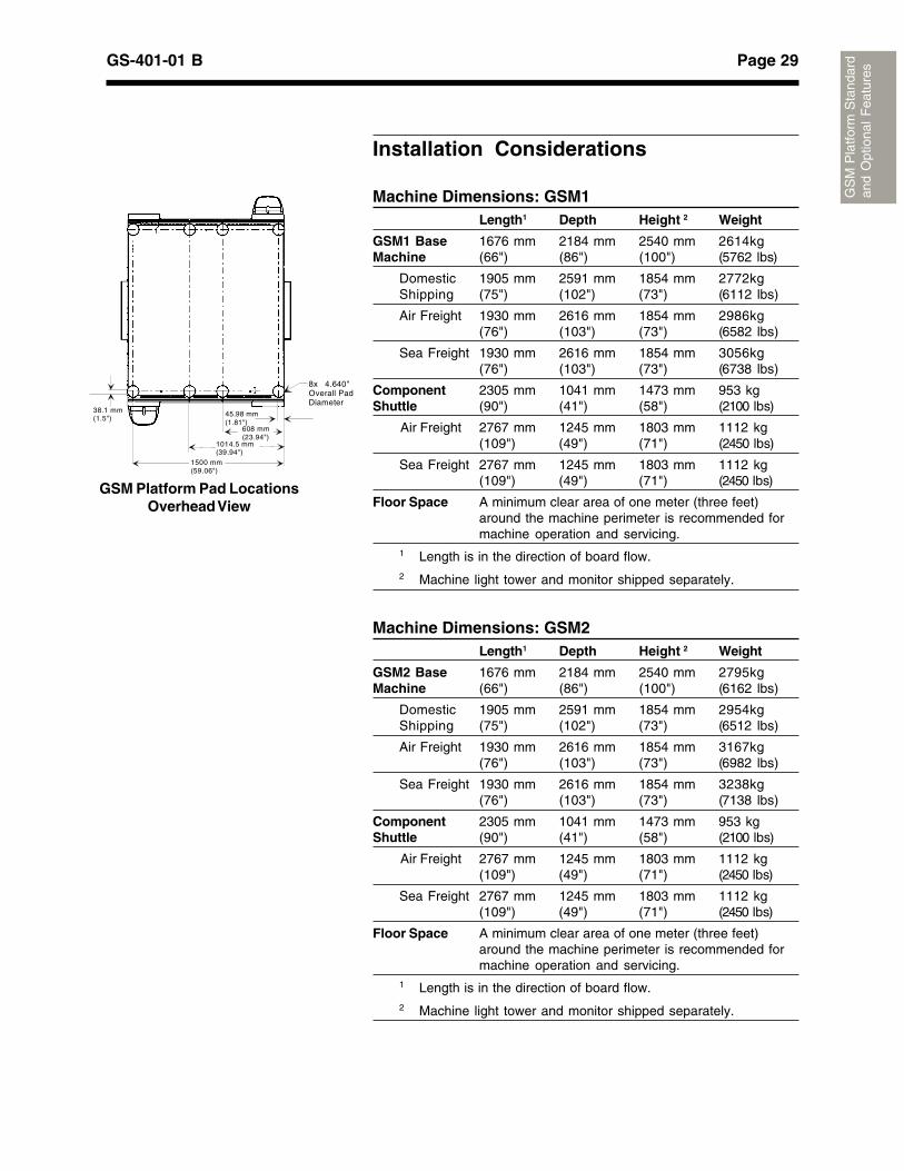
Installation Considerations
Machine Dimensions: GSM1Length1 Depth Height 2 Weight
GSM1 Base 1676 mm 2184 mm 2540 mm 2614kgMachine (66") (86") (100") (5762 lbs)
Domestic 1905 mm 2591 mm 1854 mm 2772kgShipping (75") (102") (73") (6112 lbs)
Air Freight 1930 mm 2616 mm 1854 mm 2986kg(76") (103") (73") (6582 lbs)
Sea Freight 1930 mm 2616 mm 1854 mm 3056kg(76") (103") (73") (6738 lbs)
Component 2305 mm 1041 mm 1473 mm 953 kgShuttle (90") (41") (58") (2100 lbs)
Air Freight 2767 mm 1245 mm 1803 mm 1112 kg(109") (49") (71") (2450 lbs)
Sea Freight 2767 mm 1245 mm 1803 mm 1112 kg(109") (49") (71") (2450 lbs)
Floor Space A minimum clear area of one meter (three feet)around the machine perimeter is recommended formachine operation and servicing.
1 Length is in the direction of board flow.2 Machine light tower and monitor shipped separately.
Machine Dimensions: GSM2Length1 Depth Height 2 Weight
GSM2 Base 1676 mm 2184 mm 2540 mm 2795kgMachine (66") (86") (100") (6162 lbs)
Domestic 1905 mm 2591 mm 1854 mm 2954kgShipping (75") (102") (73") (6512 lbs)
Air Freight 1930 mm 2616 mm 1854 mm 3167kg(76") (103") (73") (6982 lbs)
Sea Freight 1930 mm 2616 mm 1854 mm 3238kg(76") (103") (73") (7138 lbs)
Component 2305 mm 1041 mm 1473 mm 953 kgShuttle (90") (41") (58") (2100 lbs)
Air Freight 2767 mm 1245 mm 1803 mm 1112 kg(109") (49") (71") (2450 lbs)
Sea Freight 2767 mm 1245 mm 1803 mm 1112 kg(109") (49") (71") (2450 lbs)
Floor Space A minimum clear area of one meter (three feet)around the machine perimeter is recommended formachine operation and servicing.
1 Length is in the direction of board flow.2 Machine light tower and monitor shipped separately.
GSM Platform Pad LocationsOverhead View
8x 4.640"Overall Pad Diameter
45.98 mm(1.81")
38.1 mm(1.5")
608 mm(23.94")
1014.5 mm(39.94")
1500 mm(59.06")
Page 30 GS-401-01 B
GS
M P
latfo
rm S
tand
ard
and
Opt
iona
l F
eatu
res
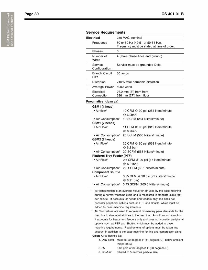
Service RequirementsElectrical 230 VAC, nominal
Frequency 50 or 60 Hz (49-51 or 59-61 Hz).Frequency must be stated at time of order.
Phases 3
Number of 4 (three phase lines and ground)Wires
Service Service must be grounded DeltaConfiguration
Branch Circuit 30 ampsSize
Distortion <10% total harmonic distortion
Average Power 5000 watts
Electrical 76.2 mm (3") from frontConnection 686 mm (27") from floor
Pneumatics (clean air)
GSM1 (1 head)• Air flow1 10 CFM @ 90 psi (284 liters/minute
@ 6.2bar)• Air Consumption2 10 SCFM (284 Nliters/minute)
GSM1 (2 heads)• Air Flow1 11 CFM @ 90 psi (312 liters/minute
@ 6.2bar)• Air Consumption2 20 SCFM (566 Nliters/minute)
GSM2 (2 heads)• Air Flow1 20 CFM @ 90 psi (568 liters/minute
@ 6.2 bar)• Air Consumption2 20 SCFM (568 Nliters/minute)
Platform Tray Feeder (PTF)• Air Flow1 0.6 CFM @ 90 psi (17 liters/minute
@ 6.21bar)• Air Consumption2 2.3 SCFM (65.1 Nliters/minute)
Component Shuttle• Air Flow1 0.75 CFM @ 90 psi (21.2 liters/minute
@ 6.21 bar)• Air Consumption2 3.73 SCFM (105.6 Nliters/minute)
1 Air consumption is an average value for air used by the base machine
during a normal machine cycle and is measured in standard cubic feet
per minute. It accounts for heads and feeders only and does not
consider peripheral options such as PTF and Shuttle, which must be
added to base machine requirements.2 Air Flow values are used to represent momentary peak demands for the
machine to size input air lines to the machine. As with air consumption,
it accounts for heads and feeders only and does not consider peripheral
options such as PTF and Shuttle, which must be added to base
machine requirements. Requirements of options must be taken into
account in addition to the base machine for line and compressor sizing.
Clean Air is defined as:
1. Dew point Must be 20 degrees F (11 degrees C) below ambient
temperature
2. Oil 0.08 ppm at 82 degrees F (28 degrees C)
3. Input air Filtered to 5 microns particle size
Page 31GS-401-01 B
GS
M P
latfo
rm S
tand
ard
and
Opt
iona
l F
eatu
res
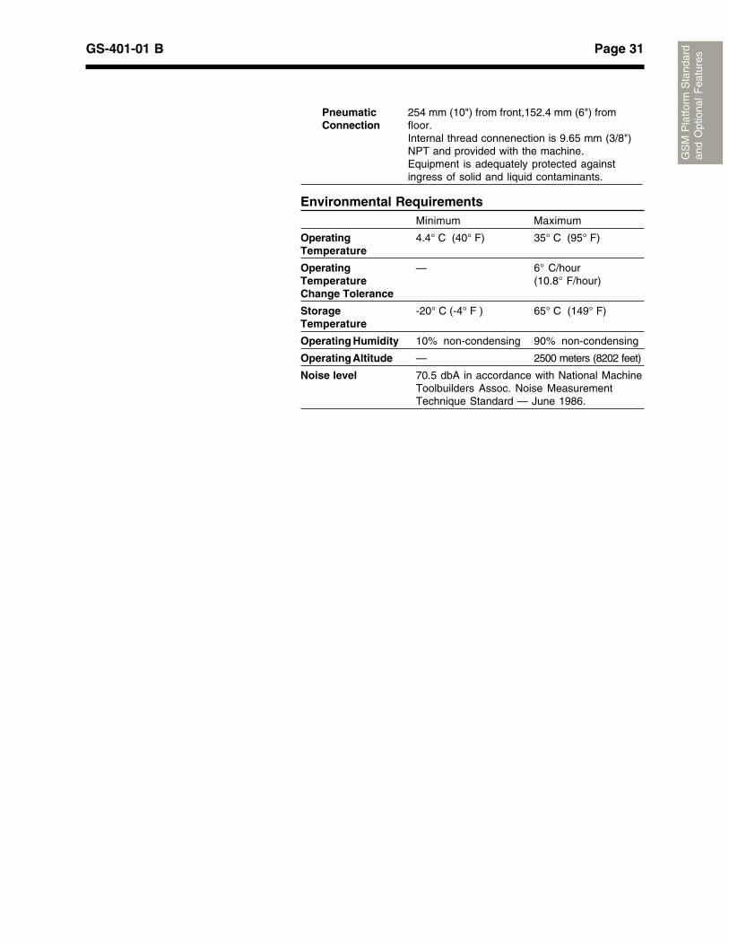
Environmental RequirementsMinimum Maximum
Operating 4.4° C (40° F) 35° C (95° F)Temperature
Operating — 6° C/hourTemperature (10.8° F/hour)Change Tolerance
Storage -20° C (-4° F ) 65° C (149° F)Temperature
Operating Humidity 10% non-condensing 90% non-condensing
Operating Altitude — 2500 meters (8202 feet)
Noise level 70.5 dbA in accordance with National MachineToolbuilders Assoc. Noise MeasurementTechnique Standard — June 1986.
Pneumatic 254 mm (10") from front,152.4 mm (6") fromConnection floor.
Internal thread connenection is 9.65 mm (3/8")NPT and provided with the machine.Equipment is adequately protected againstingress of solid and liquid contaminants.

Page 32 GS-401-01 B
GS
M P
latfo
rm S
tand
ard
and
Opt
iona
l F
eatu
res
This page intentionally left blank.
A - 33Appendix A: GSM Platform Feeders - GS-401-01 B
Fee
ders
Appendix A: GSM Platform Feeders
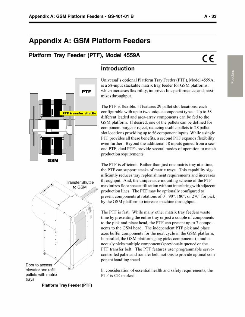
Platform Tray Feeder (PTF), Model 4559A
Introduction
����������� ������������������������������������������������������ �����!"�#�������$�����������������%&�� ��������'(�!(���!���������$�#�������� ���������� ��������!���������$����)����(�� *( �+
�(�����������$�#�+��,������ ����-�� ���������!����������!(!����* ��#��'��(� �����'�� ��. ��!�� �������� ��+��� �������������������������������������!�� �������!���#����������(�%&�� ������+��,�������������������(�� �����!���#�������������!�� ������ �*�������/�!������ !��*� ��#�� ��������-�� ��������!������� �������*� �����0�!�� �������� ��+�1(��������*����� �����������(����#�������������!���������$ �������$�#���������� ��(��+��2�������(����������������� ���*���������������!����������� ������� ������������������������ ��������������!( ��� !�������. ��������+
�(�������������!����+��3��(����(���/ ������������$�����������������(������!���� �������!"����������$������+���(���!� �#�������*�����!�������� !���������� ����(�������. ���������������!�������(�� *( �+��������(�� ��. ��������� ����*��!(��������(�������$���)��������� �!�� ���)������'��(� ������������*�'��(���/�!��� ��� !���������+���(����������#��� �������!����* ������ �������!�� �����������������������45���45��6�45�����-745����� �!"#���(��%&�� ������������!��������!(�����(�� *( �+
�(�������������+��1(����������(��������$��������������'���������#�� ��������*��(�����������������/ �����!� �����!�� ����������(�� �!"����� �!��(������(������!��� ������� ����7�!�� ������������(��%&��(���+���(������ ����������� �!"����� �!��$���# �����!�� ������������(����$��!�!������(��%&�� ������+,�� �������(��%&�� �������*��*� �!"��!�� ����������� ������ ��� �!"��� �� ��!�� �������� ����� ���. � �������(��������������#��+���(���������� ���� ���� ��*�����#��������!�������� �����������������#�������������� �������� �����!��� ������(�����*�� ���+
,��!�������������������������(���(��������������. �����������(��������89����"��+
Transfer Shuttleto GSM
Door to accesselevator and refillpallets with matrixtrays
Platform Tray Feeder (PTF)
���
�37)�WUDQVIHU�VKXWWOH
����

A - 34 GS-401-01 B - Appendix A: GSM Platform FeedersF
eede
rs
Functional Description
�(�� �������� �!���������(������������ �������!�� ����������������$�����������*��*� �!"��*�#���(��%&�� ������+������!!��� ��(��(�����(��!�� ���������������$������������������� ���*��(������������!�� ����������#���������(������ !��9������� ���*��� +
�(��������:����������� ��������� �!�#������ ������;
������������������'���(���'�������!����* ��������%&�� �����������!������'�� ��. �������$�������������+�(���!����* ������� ��������660������$�������� ��+�������$��� ��8�� �������6������������#��������������8�� �����������660���������#���(����!�������+��,���(������������(������!����!���������������������(����(��<�(�'�������%&�� ��������� ������������!���#��������������������������(������+
�� ���������'���(���'�������!����* ���������%&� �������������������#�!" ��������������!(���(��+��(�#�!" �����'�������������!�� ������� ������(�� �������������� �������� �!���!�!�� ����������(�� �����������������(������������������+�=�!���(�� �����������������������(��!�� ������'��#���!!������#���(�� ����������+�����$�� ���8�� ������������� �����������(�� ���������������(��#�!" ������ ����8�� �������� �����(�� ��������������������+�2��(� �����������#�!" ������� ���#��!!����#��#���(�������#���+����'��(��(��,��� ��������������%&�� ��������� ������������!����!����������������������������+��(��*��������� ��� !��#��������. �!"����� ����#���#��������!�� �����������#����+��(�#�!" �����'����$���)���(�� *( �+
���������������'���(���'�������!����* ��������%&�� �����������!���������������������+��,���(���������(�� �������������!�������������'��!(�'(��������*�!�� ��������������*��������#������(�� ����������+�����$�� �����!��8�� ������������� ���������(����������������!�� �������'��#�� �!"���������(��������������+8�� ��������'��!����� �����#�� �!"���������(�������������� ����8�� ����������������*��������#����(����!�� ������'����!���*����#�� �!"���������(�� ���������+��2��( ������ ���#���!!����#��#���(�������#���+�(������������ **������'(����(�� �������������!������������*�)���������#���!��+
Platform Tray Feeder (PTF)(reverse view)
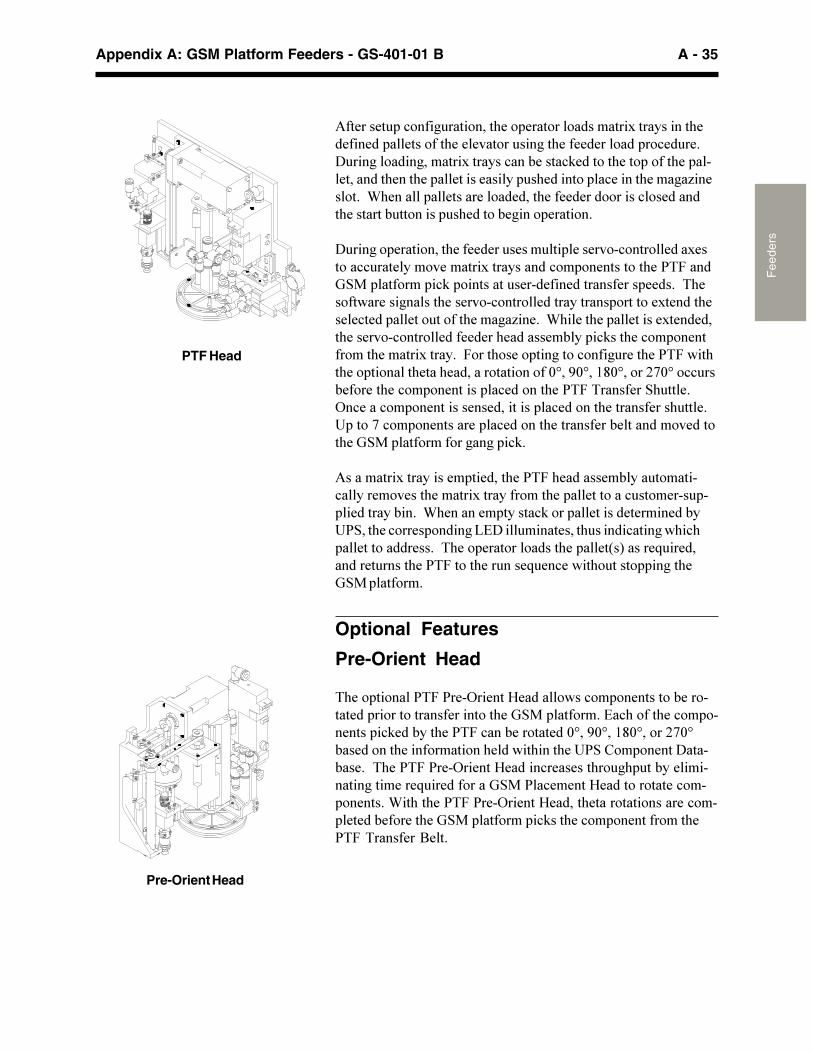
A - 35Appendix A: GSM Platform Feeders - GS-401-01 B
Fee
ders
��������� �!����* ���������(��� �����������������$�����������(��������� ���������(���������� ���*��(������������� ��!�� ��+> ���*������*�������$�������!���#�����!"�������(���� �����(�� �����������(����(�� ������������� �(�������� �!������(����*�)������+��1(����� �����������������(�����������������!���������(��������# �������� �(������#�*���� �������+
> ���*�� ����������(��������� ����� �� ��������!���������$������!! ����������������$�����������!�� �����������(���������%&�� ������� �!"� ��������� ���������������������� ����+���(�����'������*�����(��������!������������������ ��������$������(����!���� ����� ������(����*�)���+��1(����(�� ��������$��������(��������!���������������(���������#�� �!"���(��!�� �����������(�������$�����+�������(����� ���*����!����* ����(������'��(�(��� �������(����(�������������������45���45��6�45�����-745��!! ��#�������(��!�� ��������� �!�������(���������������&( ���+=�!����!�� ����������������������� �!�������(������������( ���+� ����7�!�� ����������� �!�������(�����������#����������������(��%&�� �����������*��*� �!"+
����������$����������� �������(������(���������#��� �������!������������(�������$������������(�� ���������! �������� � ���������#��+��1(�������� ������!"���� ������������������#���&���(��!����� �����*�?9>�� ����������( ������!����*�'(�!( ��������������+���(��� �������������(�� ������������. ������������ �����(����������(��� ����. ��!��'��(� ����� ��*��(�%&�� ������+
Optional Features
Pre-Orient Head
�(��� ��������������=������@������'��!�� ����������#����������� �����������������������(��%&�� ������+�9�!(�����(��!�� �������� �!"���#���(������!���#����������45���45��6�45�����-745#���������(��������������(���'��(����(����&�8�� ������>����#���+���(����������=������@������!��������(�� *( ��#������������*��������. �����������%&����!������@��������������!��� ������+�1��(��(����������=������@������(������������������!��� �����#�������(��%&�� ������� �!"���(��!�� ������������(��������������2��+
Pre-Orient Head
PTF Head
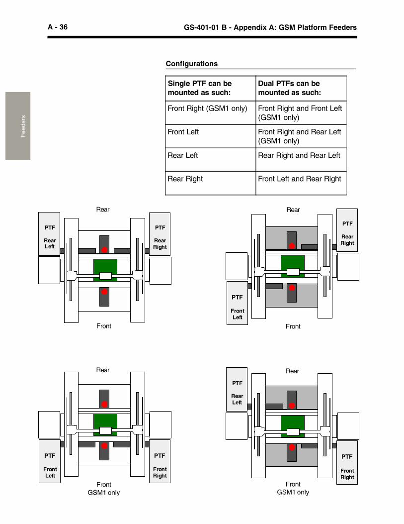
A - 36 GS-401-01 B - Appendix A: GSM Platform FeedersF
eede
rs
Configurations
PTF
RearRight
PTF
FrontLeft
PTF
FrontRight
PTF
FrontLeft
PTF
RearLeft
PTF
FrontRight
PTF
RearRight
PTF
RearLeft
FrontFront
FrontGSM1 only
FrontGSM1 only
Rear Rear
Rear Rear
Single PTF can bemounted as such:
Dual PTFs can bemounted as such:
Front Right (GSM1 only) Front Right and Front Left(GSM1 only)
Front Left Front Right and Rear Left(GSM1 only)
Rear Left Rear Right and Rear Left
Rear Right Front Left and Rear Right
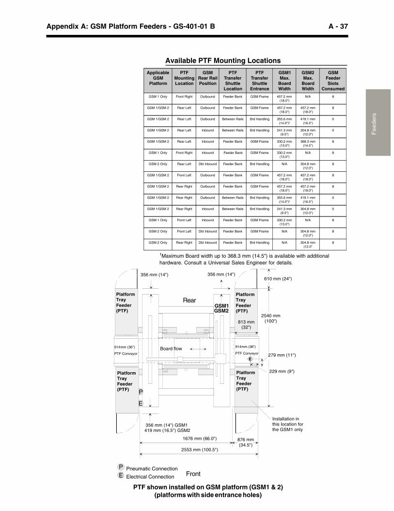
A - 37Appendix A: GSM Platform Feeders - GS-401-01 B
Fee
ders
PTF shown installed on GSM platform (GSM1 & 2)(platforms with side entrance holes)
Rear
Front
Available PTF Mounting Locations
GSM1
914mm (36")
PTF Conveyor
914mm (36")
PTF ConveyorBoard flow
P
E
Pneumatic Connection
Electrical Connection
PE
PlatformTray Feeder(PTF)
PlatformTray Feeder(PTF)
PlatformTray Feeder(PTF)
PlatformTray Feeder(PTF)
1676 mm (66.0")
813 mm (32")
356 mm (14") GSM1419 mm (16.5") GSM2
E
356 mm (14") 356 mm (14")
2540 mm (100")
279 mm (11")
610 mm (24")
229 mm (9")
876 mm (34.5")
2553 mm (100.5")
Installation in this location for the GSM1 only
GSM2
ApplicableGSM
Platform
PTFMountingLocation
GSMRear RailPosition
PTFTransferShuttle
Location
PTFTransferShuttle
Entrance
GSM1Max.
BoardWidth
GSM2Max.
BoardWidth
GSMFeederSlots
Consumed
GSM 1 Only Front Right Outbound Feeder Bank GSM Frame 457.2 mm(18.0")
N/A 8
GSM 1/GSM 2 Rear Left Outbound Feeder Bank GSM Frame 457.2 mm(18.0")
457.2 mm(18.0")
8
GSM 1/GSM 2 Rear Left Outbound Between Rails Brd Handling 355.6 mm(14.0")2
419.1 mm(16.5")
0
GSM 1/GSM 2 Rear Left Inbound Between Rails Brd Handling 241.3 mm(9.5")
304.8 mm(12.0")
0
GSM 1/GSM 2 Rear Left Inbound Feeder Bank GSM Frame 330.2 mm(13.0")
368.3 mm(14.5")
8
GSM 1 Only Front Right Inbound Feeder Bank GSM Frame 330.2 mm(13.0")
N/A 8
GSM 2 Only Rear Left Dbl Inbound Feeder Bank Brd Handling N/A 304.8 mm(12.0")
8
GSM 1/GSM 2 Front Left Outbound Feeder Bank GSM Frame 457.2 mm(18.0")
457.2 mm(18.0")
8
GSM 1/GSM 2 Rear Right Outbound Feeder Bank GSM Frame 457.2 mm(18.0")
457.2 mm(18.0")
8
GSM 1/GSM 2 Rear Right Outbound Between Rails Brd Handling 355.6 mm(14.0")2
419.1 mm(16.5")
0
GSM 1/GSM 2 Rear Right Inbound Between Rails Brd Handling 241.3 mm(9.5")
304.8 mm(12.0")
0
GSM 1 Only Front Left Inbound Feeder Bank GSM Frame 330.2 mm(13.0")
N/A 8
GSM 2 Only Front Left Dbl Inbound Feeder Bank GSM Frame N/A 304.8 mm(12.0")
8
GSM 2 Only Rear Right Dbl Inbound Feeder Bank Brd Handling N/A 304.8 mm(12.0"
8
1Maximum Board width up to 368.3 mm (14.5") is available with additionalhardware. Consult a Universal Sales Engineer for details.
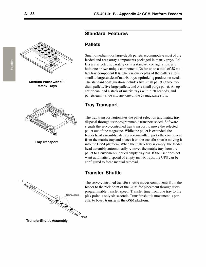
A - 38 GS-401-01 B - Appendix A: GSM Platform FeedersF
eede
rs
�(������������ ����� ���������(�� �������!��������������$�������� �����(�� *(� ���� ��*�����#������� ����� ���+�&���'�����*�����(��������!������������������ �������������(�����!��� ����� ������(����*�)���+�1(����(�� ��������$���������(��������(���������#�������������!��������� �!"���(��!�� �����������(�������$���������� �!����������(������������( ���������*���������(��%&�� ������+�1(����(�������$����������� �����(��������(���������#��� ������!������������(�������$������������(� ���������! �������� ������ ��������#��+�,���(�� ������������'����� ������!���� ��������� ��������$���������(����&�!���#�!����* ����������!����� ��������+
Pallets
&��������� ���������*���� �(� ������!!������������������(����������������������!�� ������� �!"�*�����������$������+���������������!������ ������������������������!����* �����������(�����������'�� ��. ��!�� ������,>������ �����������������������$������!�� ������,>�+��(������� ���� �(������(�� �������'���������*�����!"����������$��������� ����)��*� ��� !����������+�(�����������!����* ���������! ������������� �������(��������� �� �������������*�� ������������������ �*�� ���+����� ��������!������������!"���������$�������'��(���-4���!��������� ���������������������������������(��-����*�)��������+
Tray Transport
Transfer Shuttle
�(��������!������������������( ����������!�� �������������(������������(�� �!"� ���������(��%&������ �!�������(�� *(� ���� ��*�����#������������ ���+���������������������������������(� �!"� ��������������$���!����+�����������( ���������������� ���������#������������������(��%&�� ������+
Tray Transport
Transfer Shuttle Assembly
Medium Pallet with fullMatrix Trays
GSM
PTF
Components
Standard Features
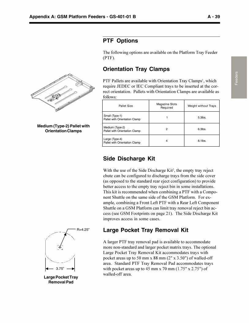
A - 39Appendix A: GSM Platform Feeders - GS-401-01 B
Fee
ders
PTF Options
�(�����'��*�� ���������������#������(��������������������������+
Orientation Tray Clamps
�������������������#��'��(�=����������������8�� ����'(�!(��. ����A9>98����,98�8�� ��������������#���������������(��!�����!�������������+��������'��(�=�����������8�� �����������#�������'�;
Medium (Type-2) Pallet withOrientation Clamps
R=4.25”
3.75”
Side Discharge Kit
1��(��(�� �������(��&����>��!(��*��B������(���� ����������/�!�!( ���!���#��!����* ����������!(��*��������������(�������!��������� ���������(�����������������/�!��!����* ����������� ������#�������!!��������(���� ����������/�!��#����������������������+�(���"��������!���������'(���!��#����*�������'��(���8�� �������&( ��������(����������������(��%&���������+�������$��� ���!��#����*���������?��������'��(���3����?����8�� �����&( ���������%&����������!����������������������/�!��#����!�!���������%&������ ��������� �*��-6�+���(��&����>��!(��*��B���� �������!!������������!����+
Large Pocket Tray Removal Kit
����*������������������� �����������#������!!��������������������������������*��� �!"��������$������+��(��� �����?��*����!"��������3������B����!!����������������'��( �!"��������� �����4����$��������-C�$�:+�4C�����'�����������+��&�����������������3�����������!!���������������'��(� �!"��������� ����������$�74�����6+7�C�$�-+7�C����'������������+
Large Pocket TrayRemoval Pad
eziStellaPstolSenizagaM
deriuqeRsyarTtuohtiwthgieW
)1-epyT(llamSpmalCnoitatneirOhtiwtellaP
1 .sbl3.5
)2-epyT(muideMpmalCnoitatneirOhtiwtellaP
2 .sbl3.6
)4-epyT(egraLpmalCnoitatneirOhtiwtellaP
4 .sbl1.8
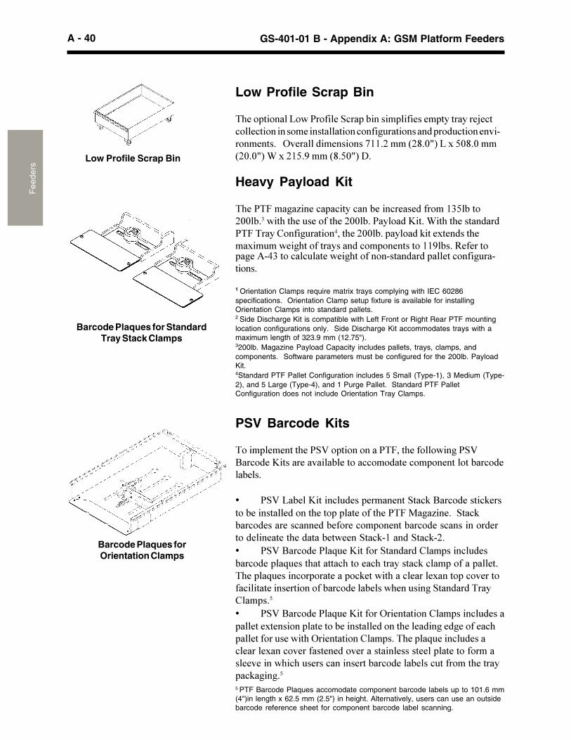
A - 40 GS-401-01 B - Appendix A: GSM Platform FeedersF
eede
rs
Low Profile Scrap Bin
�(��� ������?�'��������&!�� �#������ �������� ����������/�!�!��!������������������������!����* ������������ ��� !������������������+���=����������������766+-�����-�+4C��?�$��4�+4����-4+4C��1�$�-6�+�������+�4C��>+
Heavy Payload Kit
�(��������*�)����!� �!����!���#����!������������6:�#���-44#+��'��(��(�� �������(��-44#+��������B��+�1��(��(�������������������8����* ����������(��-44#+� ������"����$�������(���$�� ��'��*(���������������!�� ����������66�#�+�3�������
Low Profile Scrap Bin
�*�����:����!�! ����'��*(������������������ ����!����* ��������+
1 Orientation Clamps require matrix trays complying with IEC 60286specifications. Orientation Clamp setup fixture is available for installingOrientation Clamps into standard pallets.2 Side Discharge Kit is compatible with Left Front or Right Rear PTF mountinglocation configurations only. Side Discharge Kit accommodates trays with amaximum length of 323.9 mm (12.75").3200lb. Magazine Payload Capacity includes pallets, trays, clamps, andcomponents. Software parameters must be configured for the 200lb. PayloadKit.4Standard PTF Pallet Configuration includes 5 Small (Type-1), 3 Medium (Type-2), and 5 Large (Type-4), and 1 Purge Pallet. Standard PTF PalletConfiguration does not include Orientation Tray Clamps.
PSV Barcode Kits
����� �������(���&D�� ����������������(�����'��*��&D2��!����B�������������#������!!��������!�� ���������#��!����#��+
� �&D�?�#��B�����! ���� ���������&��!"�2��!�������!"������#��������������(���� � ��������(��������*�)���+��&��!"#��!����������!������#������!�� ������#��!�����!�������������������������(�������#��'����&��!"�6�����&��!"�-+� �&D�2��!������. ��B�������&��������8�� ����! ���#��!���� �. ����(�������!(������!(���������!"�!�� ������ ���+�(�� �. �����!�� �������� �!"���'��(���!�����$����� �!���������!��������������������#��!�����#���'(��� ���*�&������������8�� �+�
� �&D�2��!������. ��B�������=�����������8�� ����! ����� �����$�������� �������#��������������(�������*���*�������!( �������� ���'��(�=�����������8�� �+��(�� �. ����! �����!�����$���!����������������������������������� ����������������������'(�!(� �����!����������#��!�����#���! ��������(������ �!"�*��*+�5 PTF Barcode Plaques accomodate component barcode labels up to 101.6 mm(4")in length x 62.5 mm (2.5") in height. Alternatively, users can use an outsidebarcode reference sheet for component barcode label scanning.
Barcode Plaques for StandardTray Stack Clamps
Barcode Plaques forOrientation Clamps
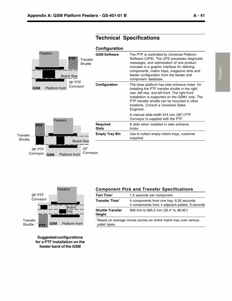
A - 41Appendix A: GSM Platform Feeders - GS-401-01 B
Fee
ders
Technical Specifications
ConfigurationGSM Software The PTF is controlled by Universal Platform
Software (UPS). The UPS processes diagnosticmessages, and optimization of one product.Included is a graphic interface for definingcomponents, matrix trays, magazine slots andfeeder configuration from the feeder andcomponent database.
Configuration The base platform has side entrance holes forinstalling the PTF transfer shuttle in the rightrear, left rear, and left front. The right frontinstallation is supported on the GSM1 only. ThePTF transfer shuttle can be mounted in otherlocations. Consult a Universal SalesEngineer.
A manual slide-width 914 mm (36") PTFConveyor is supplied with the PTF.
Required 8 slots when installed in side entranceSlots holes.
Empty Tray Bin Use to collect empty matrix trays, customersupplied.
Component Pick and Transfer SpecificationsTact Time1 1.5 seconds per component
Transfer Time1 4 components from one tray: 6.25 seconds4 components from 4 adjacent pallets: 9 seconds
Shuttle Transfer 899 mm to 965.2 mm (35.4" to 38.00")Height1 Based on average moves across an entire matrix tray over variouspallet types.
Suggested configurationsfor a PTF installation on the
feeder bank of the GSM
Platform front
36" PTFConveyor
Board flow
PTF TransferShuttle
GSM
Feeders
Platform front
Boardflow
PTF GSM
36" PTFConveyor
TransferShuttle
Feeders
Platform front
22"Conveyor
Board flow
PTF
GSM
36" PTFConveyor
TransferShuttle
Feeders
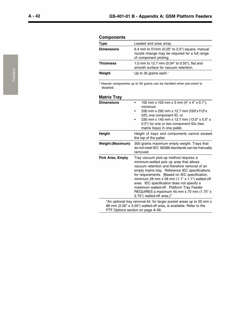
A - 42 GS-401-01 B - Appendix A: GSM Platform FeedersF
eede
rs
ComponentsType Leaded and area array
Dimensions 6.4 mm to 51mm (0.25" to 2.0") square, manualnozzle change may be required for a full rangeof component picking.
Thickness 1.0 mm to 12.7 mm (0.04" to 0.50"), flat andsmooth surface for vacuum retention.
Weight Up to 35 grams each.1
1 Heavier components up to 50 grams can be handled when pre-orient isdisabled.
Matrix TrayDimensions • 102 mm x 102 mm x 3 mm (4" x 4" x 0.1"),
minimum• 330 mm x 292 mm x 12.7 mm (13.0" x 11.5" x
0.5"), one component ID, or• 330 mm x 140 mm x 12.7 mm (13.0" x 5.5" x
0.5") for one or two component IDs (twomatrix trays) in one pallet.
Height Height of trays and components cannot exceedthe top of the pallet.
Weight (Maximum) 300 grams maximum empty weight. Trays thatdo not meet IEC 60286 standards can be manuallyremoved.
Pick Area, Empty Tray vacuum pick-up method requires aminimum-walled pick up area that allowsvacuum retention and therefore removal of anempty matrix tray. Reference IEC specificationsfor requirements. [Based on IEC specification,minimum 28 mm x 28 mm (1.1" x 1.1") walled-offarea. IEC specification does not specify amaximum walled-off. Platform Tray FeederREQUIRES a maximum 45 mm x 70 mm (1.75" x2.75") walled-off area.]*
*An optional tray removal kit, for larger pocket areas up to 50 mm x88 mm (2.00" x 3.50") walled-off area, is available. Refer to thePTF Options section on page A-39.
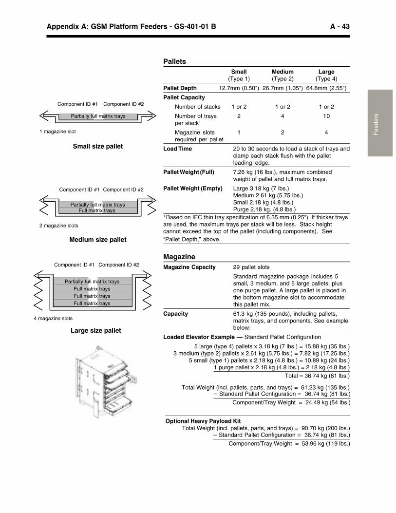
A - 43Appendix A: GSM Platform Feeders - GS-401-01 B
Fee
ders
PalletsSmall Medium Large
(Type 1) (Type 2) (Type 4)
Pallet Depth 12.7mm (0.50") 26.7mm (1.05") 64.8mm (2.55")
Pallet Capacity
Number of stacks 1 or 2 1 or 2 1 or 2
Number of trays 2 4 10per stack1
Magazine slots 1 2 4required per pallet
Load Time 20 to 30 seconds to load a stack of trays andclamp each stack flush with the palletleading edge.
Pallet Weight (Full) 7.26 kg (16 lbs.), maximum combinedweight of pallet and full matrix trays.
Pallet Weight (Empty) Large 3.18 kg (7 lbs.)Medium 2.61 kg (5.75 lbs.)Small 2.18 kg (4.8 lbs.)Purge 2.18 kg. (4.8 lbs.)
1 Based on IEC thin tray specification of 6.35 mm (0.25"). If thicker traysare used, the maximum trays per stack will be less. Stack heightcannot exceed the top of the pallet (including components). See“Pallet Depth,” above.
MagazineMagazine Capacity 29 pallet slots
Standard magazine package includes 5small, 3 medium, and 5 large pallets, plusone purge pallet. A large pallet is placed inthe bottom magazine slot to accommodatethis pallet mix.
Capacity 61.3 kg (135 pounds), including pallets,matrix trays, and components. See examplebelow:
Loaded Elevator Example — Standard Pallet Configuration
5 large (type 4) pallets x 3.18 kg (7 lbs.) = 15.88 kg (35 lbs.)3 medium (type 2) pallets x 2.61 kg (5.75 lbs.) = 7.82 kg (17.25 lbs.)
5 small (type 1) pallets x 2.18 kg (4.8 lbs.) = 10.89 kg (24 lbs.)1 purge pallet x 2.18 kg (4.8 lbs.) = 2.18 kg (4.8 lbs.)
Total = 36.74 kg (81 lbs.)
Total Weight (incl. pallets, parts, and trays) = 61.23 kg (135 lbs.)– Standard Pallet Configuration = 36.74 kg (81 lbs.)
Component/Tray Weight = 24.49 kg (54 lbs.)
Optional Heavy Payload Kit
2 magazine slots
Full matrix traysPartially full matrix trays
Medium size pallet
Component ID #1 Component ID #2
1 magazine slot
Small size pallet
Partially full matrix trays
Component ID #2 Component ID #1
4 magazine slots
Full matrix traysPartially full matrix trays
Large size pallet
Full matrix traysFull matrix trays
Component ID #1 Component ID #2
Total Weight (incl. pallets, parts, and trays) = 90.70 kg (200 lbs.)– Standard Pallet Configuration = 36.74 kg (81 lbs.)
Component/Tray Weight = 53.96 kg (119 lbs.)
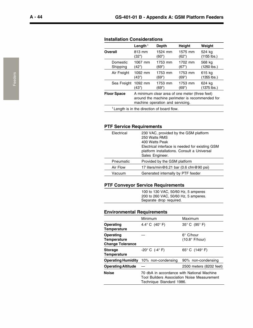
A - 44 GS-401-01 B - Appendix A: GSM Platform FeedersF
eede
rs
Installation ConsiderationsLength 1 Depth Height Weight
Overall 813 mm 1524 mm 1575 mm 524 kg(32") (60") (62") (1155 lbs.)
Domestic 1067 mm 1753 mm 1702 mm 568 kgShipping (42") (69") (67") (1250 lbs.)
Air Freight 1092 mm 1753 mm 1753 mm 615 kg(43") (69") (69") (1355 lbs.)
Sea Freight 1092 mm 1753 mm 1753 mm 624 kg(43") (69") (69") (1375 lbs.)
Floor Space A minimum clear area of one meter (three feet)around the machine perimeter is recommended formachine operation and servicing.
1 Length is in the direction of board flow.
PTF Service RequirementsElectrical 230 VAC, provided by the GSM platform
250 Watts RMS400 Watts PeakElectrical interface is needed for existing GSMplatform installations. Consult a UniversalSales Engineer.
Pneumatic Provided by the GSM platform
Air Flow 17 liters/[email protected] bar (0.6 cfm@90 psi)
Vacuum Generated internally by PTF feeder
PTF Conveyor Service Requirements100 to 130 VAC, 50/60 Hz, 5 amperes200 to 260 VAC, 50/60 Hz, 5 amperes.Separate drop required.
Environmental RequirementsMinimum Maximum
Operating 4.4° C (40° F) 35° C (95° F)Temperature
Operating — 6° C/hourTemperature (10.8° F/hour)Change Tolerance
Storage -20° C (-4° F) 65° C (149° F)Temperature
Operating Humidity 10% non-condensing 90% non-condensing
Operating Altitude — 2500 meters (8202 feet)
Noise 70 dbA in accordance with National MachineTool Builders Association Noise MeasurementTechnique Standard 1986.

A - 45Appendix A: GSM Platform Feeders - GS-401-01 B
Fee
ders
Supporting Documents
,������������9�!�����!(��!��8�����������,98��&���������04-�0�������������6����4-�������!"�*��*����8�� ����������� ������!�@�����*
&�9���&���'���E8��� ��!�������,������!��&��������-+4
F���������!(��������2 ����������!�������F��������� ��������!(��. ��&���������6��0+

A - 46 GS-401-01 B - Appendix A: GSM Platform FeedersF
eede
rs
Stackable Matrix Tray Feeder
Stackable Matrix Tray Feeder, Model 4556A
Introduction�(���&��!"�#�������$����������������������0�������������!"���������$���������������'��(�!�� �������������� ���� �#�������(�� �!"� ������������(��%&�� ������+��9� ���������������!�����+��D�! �� �!" ���. �����������'��(��������(�� ����!�����������#�!"��� �!"����������(��!����������(������+
Standard Features�(����� ���!�� �!���������'������� ��������+-������:+7�C��0+�4"*��6�+4�#�+�����!"���������$�����������(�� �!"� �������+���'���)�������������������#�+��������(����(���������������$�������)����!��� �������������&����9�*�����+
G ������������6:�+��������6��+�������+:�C����0+64C��'����#�-00+7�������::4+-�����64+�C����6:C����*������$������+%&�6����%&�-�
G ������������6:�+��������-6-+�������+:�C�����+:�C��'����#�-00+7�������::4+-�����64+�C����6:C�������$������+��%&����%&�-�
G �������������6:�+��������-6-+�������+:�C�����+:�C���'���#��-00+7�������::4+-�����64+�C����6:C�������$������+����������������$�����������45���������+�%&�-����+
Functional Description�����!"���������$���������� �������������(��%&�� ����������!�� ������ �!" +���(��%&�� ������� �!"��������(���� �����+1(����(���� ����������� �����(�����!"�����������(�����!���� ��������+��(���� ����������� �!"���� �!������*��(����$��� ������$����+���(����������*����������!"���� ��������(�� �!"�������'(���(���� ��������������!���������� ������� ������!��+����� ���!"���������$������������� ������������������+�� ������!�������������������������������!��������*����,98�04-�0����A9>98������� �!���!������+
1 Requires the “double inbound” 127.0 mm (5") real rail location for GSM2installation. See Page 23. Limitations apply. Contact a Universal SalesEngineer.2 Requires the “inbound” 127.0 mm (5") or "double inbound" 215.9 mm (8.5")rear rail position.
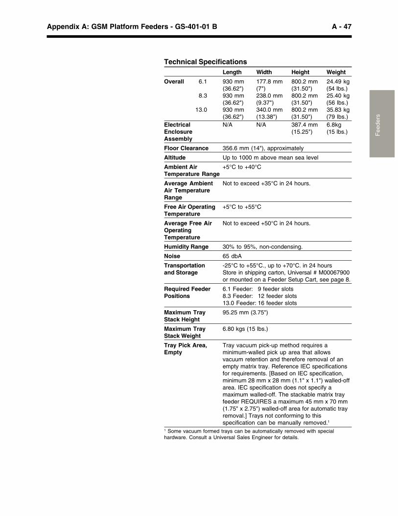
A - 47Appendix A: GSM Platform Feeders - GS-401-01 B
Fee
ders
Technical SpecificationsLength Width Height Weight
Overall 6.1 930 mm 177.8 mm 800.2 mm 24.49 kg(36.62") (7") (31.50") (54 lbs.)
8.3 930 mm 238.0 mm 800.2 mm 25.40 kg(36.62") (9.37") (31.50") (56 lbs.)
13.0 930 mm 340.0 mm 800.2 mm 35.83 kg(36.62") (13.38") (31.50") (79 lbs.)
Electrical N/A N/A 387.4 mm 6.8kgEnclosure (15.25") (15 lbs.)Assembly
Floor Clearance 356.6 mm (14"), approximately
Altitude Up to 1000 m above mean sea level
Ambient Air +5°C to +40°CTemperature Range
Average Ambient Not to exceed +35°C in 24 hours.Air TemperatureRange
Free Air Operating +5°C to +55°CTemperature
Average Free Air Not to exceed +50°C in 24 hours.OperatingTemperature
Humidity Range 30% to 95%, non-condensing.
Noise 65 dbA
Transportation -25°C to +55°C., up to +70°C. in 24 hoursand Storage Store in shipping carton, Universal # M00067900
or mounted on a Feeder Setup Cart, see page 8.
Required Feeder 6.1 Feeder: 9 feeder slotsPositions 8.3 Feeder: 12 feeder slots
13.0 Feeder: 16 feeder slots
Maximum Tray 95.25 mm (3.75")Stack Height
Maximum Tray 6.80 kgs (15 lbs.)Stack Weight
Tray Pick Area, Tray vacuum pick-up method requires aEmpty minimum-walled pick up area that allows
vacuum retention and therefore removal of anempty matrix tray. Reference IEC specificationsfor requirements. [Based on IEC specification,minimum 28 mm x 28 mm (1.1" x 1.1") walled-offarea. IEC specification does not specify amaximum walled-off. The stackable matrix trayfeeder REQUIRES a maximum 45 mm x 70 mm(1.75" x 2.75") walled-off area for automatic trayremoval.] Trays not conforming to thisspecification can be manually removed.1
1 Some vacuum formed trays can be automatically removed with specialhardware. Consult a Universal Sales Engineer for details.
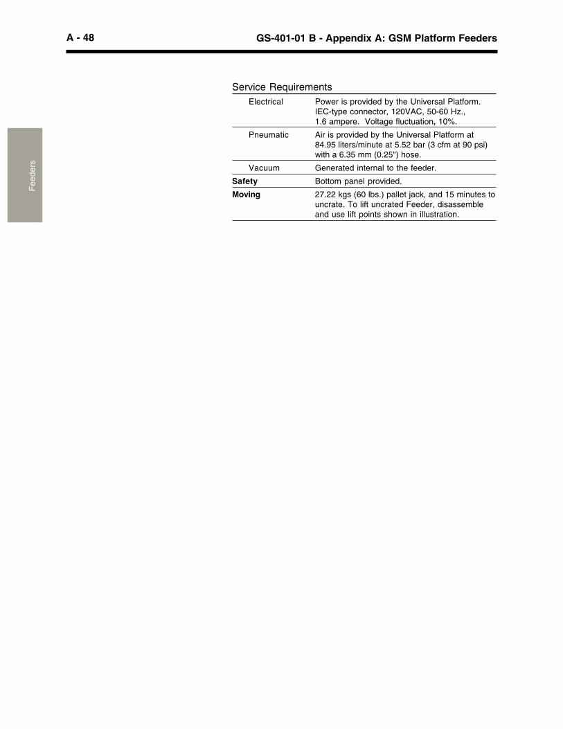
A - 48 GS-401-01 B - Appendix A: GSM Platform FeedersF
eede
rs
Service RequirementsElectrical Power is provided by the Universal Platform.
IEC-type connector, 120VAC, 50-60 Hz.,1.6 ampere. Voltage fluctuation, 10%.
Pneumatic Air is provided by the Universal Platform at84.95 liters/minute at 5.52 bar (3 cfm at 90 psi)with a 6.35 mm (0.25") hose.
Vacuum Generated internal to the feeder.
Safety Bottom panel provided.
Moving 27.22 kgs (60 lbs.) pallet jack, and 15 minutes touncrate. To lift uncrated Feeder, disassembleand use lift points shown in illustration.
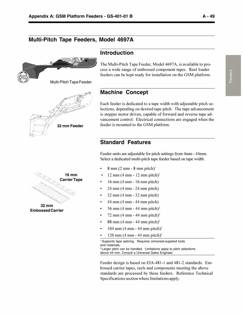
A - 49Appendix A: GSM Platform Feeders - GS-401-01 B
Fee
ders
32 mmEmbossed Carrier
16 mmCarrier Tape
32 mm Feeder
Multi-Pitch Tape Feeders, Model 4697A
Introduction
�(��� ������!(��� ����������������0�7�����������#����� ���!������'�������*�������#������!�� �������� ��+��3����������������!���#��"� ���������������������������(��%&�� ������+
Machine Concept
9�!(���������������!������������ ��'���(�'��(���/ ���#�� ��!(�����!��������� �����*�������������� �� ��!(+���(���� �������!����������� �����������������!� �#��������'������������������ ��������!������!�����+��9�!���!��!����!������������*�*���'(����(������������� ���������(��%&�� ������+
Standard Features
������� �����������/ ���#������ ��!(�������*�����������������+&��!��������!������ ��� ��!(��� ���������#���������� ��'���(+
G ������-����������� ��!(��
�G 6-������������6-���� ��!(��
G 60������������60���� ��!(�
G -�������������-����� ��!(�
G :-������������:-���� ��!(�
G �������������������� ��!(�
G �0������������������ ��!(��
G 7-������������������ ��!(��
G �������������������� ��!(��
G 64������������������� ��!(��
G 6-4������������������ ��!(��1 Supports tape splicing. Requires Universal-supplied toolsand materials.2 Larger pitch can be handled. Limitations apply to pitch selectionsabove 44 mm. Consult a Universal Sales Engineer.
�����������*�����#��������9,����6�6�������6�-����������+��9��#������!��������� �������������!�� �������������*��(���#����������������� ��!������#���(�����������+��3������!����!(��!�& �!���!���������!�����'(���������������� �+
Multi-Pitch Tape Feeder
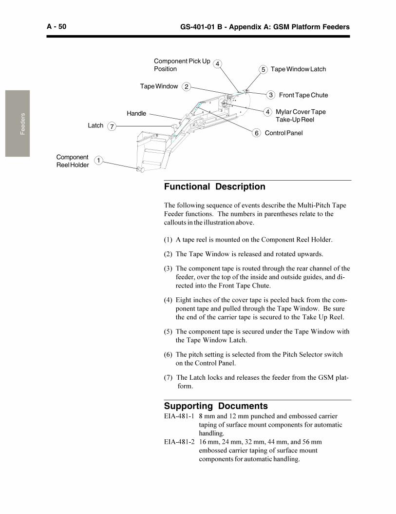
A - 50 GS-401-01 B - Appendix A: GSM Platform FeedersF
eede
rs Handle
ComponentReel Holder
1
Latch 7Control Panel6
Mylar Cover TapeTake-Up Reel
4
Front Tape Chute32Tape Window
Component Pick UpPosition
4Tape Window Latch5
Functional Description
�(�����'��*���. ��!���������������!��#���(��� ������!(��� ��������� �!�����+���(��� �#������� �����(���������������(�!�� �������(��� ����������#���+
�6� ���� ����������� ���������(��8�� ������3���@����+
�-� �(���� ��1����'������������������������ '����+
�:� �(��!�� �������� ������� �����(�� *(��(�������!(���������(���������������(���� �����(�������������� ������* ���������������!����������(���������� ��8( ��+
��� 9�*(����!(�������(��!������� ����� �����#�!"�������(��!��� �������� ������ ����(�� *(��(���� ��1����'+��2��� ���(����������(��!��������� �������! ��������(����"��� �3��+
��� �(��!�� �������� �������! ���� ������(���� ��1����'�'��(�(���� ��1����'�?��!(+
�0� �(�� ��!(�������*�������!����������(�����!(�&��!�����'��!(����(��8����������+
�7����(��?��!(��!"���������������(���������������(��%&�� ��������������+
Supporting Documents9,����6�6 ���������6-���� �!(���������#������!������
�� ��*����� ���!���� ���!�� ������������ ������!(�����*+
9,����6�- 60�����-������:-�����������������0�����#������!��������� ��*����� ���!���� ��!�� ������������ ������!�(�����*+
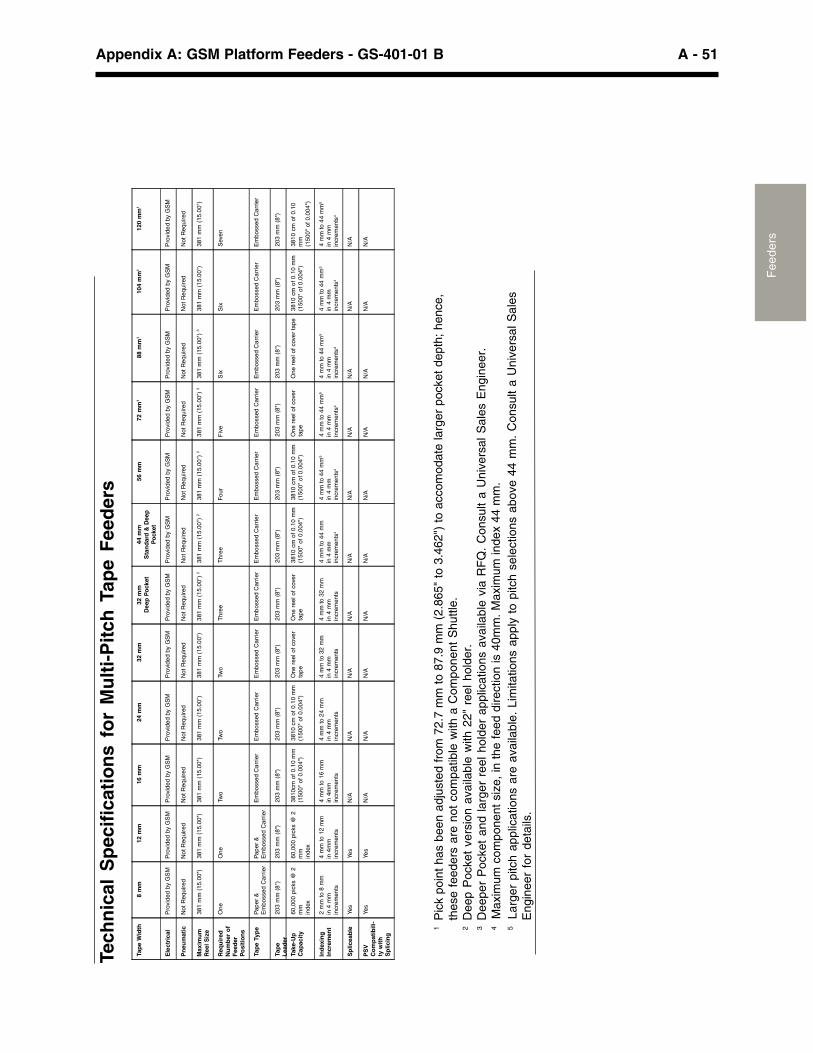
A - 51Appendix A: GSM Platform Feeders - GS-401-01 B
Fee
ders
Tech
nic
al S
pec
ific
atio
ns
for
Mu
lti-
Pit
ch T
ape
Fee
der
s
1P
ick
poin
t ha
s be
en a
djus
ted
from
72.
7 m
m t
o 87
.9 m
m (
2.86
5" t
o 3.
462"
) to
acc
omod
ate
larg
er p
ocke
t de
pth;
hen
ce,
thes
e fe
eder
s ar
e no
t co
mpa
tible
with
a C
ompo
nent
Shu
ttle.
2D
eep
Poc
ket
vers
ion
avai
labl
e w
ith 2
2" r
eel
hold
er.
3D
eepe
r P
ocke
t an
d la
rger
ree
l ho
lder
app
licat
ions
ava
ilabl
e vi
a R
FQ
. C
onsu
lt a
Uni
vers
al S
ales
Eng
inee
r.4
Max
imum
com
pone
nt s
ize,
in t
he f
eed
dire
ctio
n is
40m
m.
Max
imum
inde
x 44
mm
.5
La
rger
pitc
h ap
plic
atio
ns a
re a
vaila
ble.
Lim
itatio
ns a
pply
to
pitc
h se
lect
ions
abo
ve 4
4 m
m.
Con
sult
a U
nive
rsal
Sal
esE
ngin
eer
for
deta
ils.
Tap
e W
idth
8 m
m12
mm
16 m
m24
mm
32 m
m32
mm
Dee
p P
ock
et44
mm
Sta
nd
ard
& D
eep
Po
cket
56 m
m72
mm
188
mm
110
4 m
m1
120
mm
1
Ele
ctri
cal
Pro
vide
d by
GS
MP
rovi
ded
by G
SM
Pro
vide
d by
GS
MP
rovi
ded
by G
SM
Pro
vide
d by
GS
MP
rovi
ded
by G
SM
Pro
vide
d b
y G
SM
Pro
vide
d by
GS
MP
rovi
ded
by
GS
MP
rovi
ded
by G
SM
Pro
vide
d by
GS
MP
rovi
ded
by G
SM
Pn
eum
atic
Not
Req
uire
dN
ot R
equi
red
Not
Req
uire
dN
ot R
equ
ired
Not
Req
uire
dN
ot R
equi
red
Not
Req
uire
dN
ot R
equi
red
Not
Req
uire
dN
ot R
equ
ired
Not
Req
uire
dN
ot R
equi
red
Max
imu
mR
eel S
ize
381
mm
(15
.00"
)38
1 m
m (
15.0
0")
381
mm
(15
.00"
)38
1 m
m (
15.0
0")
381
mm
(15
.00"
)3
81 m
m (
15.0
0")
238
1 m
m (
15.0
0")
238
1 m
m (
15.0
0")
33
81 m
m (
15.0
0")
338
1 m
m (
15.0
0")
338
1 m
m (
15.
00")
381
mm
(15
.00"
)
Req
uir
edN
um
ber
of
Fee
der
Po
siti
on
s
One
One
Two
Two
Two
Thr
eeT
hree
Fou
rF
ive
Six
Six
Sev
en
Tap
e Ty
pe
Pap
er &
Em
boss
ed C
arri
erP
aper
&E
mbo
ssed
Ca
rrie
rE
mbo
ssed
Ca
rrie
rE
mbo
ssed
Car
rier
Em
boss
ed C
arri
erE
mb
osse
d C
arri
erE
mbo
ssed
Car
rier
Em
boss
ed C
arri
erE
mbo
ssed
Car
rier
Em
boss
ed C
arri
erE
mbo
ssed
Car
rier
Em
boss
ed C
arrie
r
Tap
eL
ead
er20
3 m
m (
8")
203
mm
(8"
)20
3 m
m (
8")
203
mm
(8"
)20
3 m
m (
8")
203
mm
(8"
)20
3 m
m (
8")
203
mm
(8"
)20
3 m
m (
8")
203
mm
(8"
)20
3 m
m (
8")
203
mm
(8"
)
Take
-Up
Cap
acit
y60
,000
pic
ks @
2m
min
dex
60,0
00 p
icks
@ 2
mm
inde
x
3810
cm o
f 0.
10 m
m(1
500"
of
0.00
4")
3810
cm
of
0.1
0 m
m(1
500"
of
0.00
4")
One
ree
l of c
over
tap
eO
ne r
eel o
f co
ver
tape
3810
cm
of
0.10
mm
(150
0" o
f 0.
004"
)38
10 c
m o
f 0.
10 m
m(1
500"
of 0
.004
")O
ne r
eel o
f co
ver
tape
One
ree
l of
cove
r ta
pe38
10 c
m o
f 0.1
0 m
m(1
500"
of 0
.004
")38
10
cm o
f 0.
10m
m(1
500"
of
0.00
4")
Ind
exin
gIn
crem
ent
2 m
m t
o 8
mm
in 4
mm
incr
em
ents
4 m
m to
12
mm
in 4
mm
incr
emen
ts
4 m
m to
16
mm
in 4
mm
incr
emen
ts
4 m
m t
o 2
4 m
min
4 m
min
crem
ents
4 m
m t
o 32
mm
in 4
mm
incr
emen
ts
4 m
m t
o 32
mm
in 4
mm
incr
emen
ts
4 m
m t
o 44
mm
in 4
mm
incr
emen
ts4
4 m
m t
o 44
mm
5
in 4
mm
incr
eme
nts4
4 m
m t
o 44
mm
5
in 4
mm
incr
emen
ts4
4 m
m t
o 44
mm
5
in 4
mm
incr
emen
ts4
4 m
m t
o 44
mm
5
in 4
mm
incr
eme
nts4
4 m
m t
o 4
4 m
m5
in 4
mm
incr
emen
ts4
Sp
licea
ble
Yes
Yes
N/A
N/A
N/A
N/A
N/A
N/A
N/A
N/A
N/A
N/A
PS
VC
om
pat
ibili
-ty
wit
hS
plic
ing
Yes
Yes
N/A
N/A
N/A
N/A
N/A
N/A
N/A
N/A
N/A
N/A
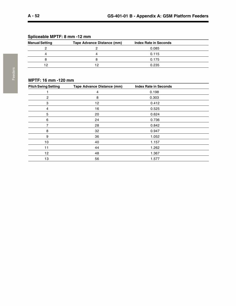
A - 52 GS-401-01 B - Appendix A: GSM Platform FeedersF
eede
rs
MPTF: 16 mm -120 mmPitch Swing Setting Tape Advance Distance (mm) Index Rate in Seconds
1 4 0.198
2 8 0.303
3 12 0.412
4 16 0.525
5 20 0.624
6 24 0.736
7 28 0.842
8 32 0.947
9 36 1.052
10 40 1.157
11 44 1.262
12 48 1.367
13 56 1.577
Spliceable MPTF: 8 mm -12 mmManual Setting Tape Advance Distance (mm) Index Rate in Seconds
2 2 0.085
4 4 0.115
8 8 0.175
12 12 0.235
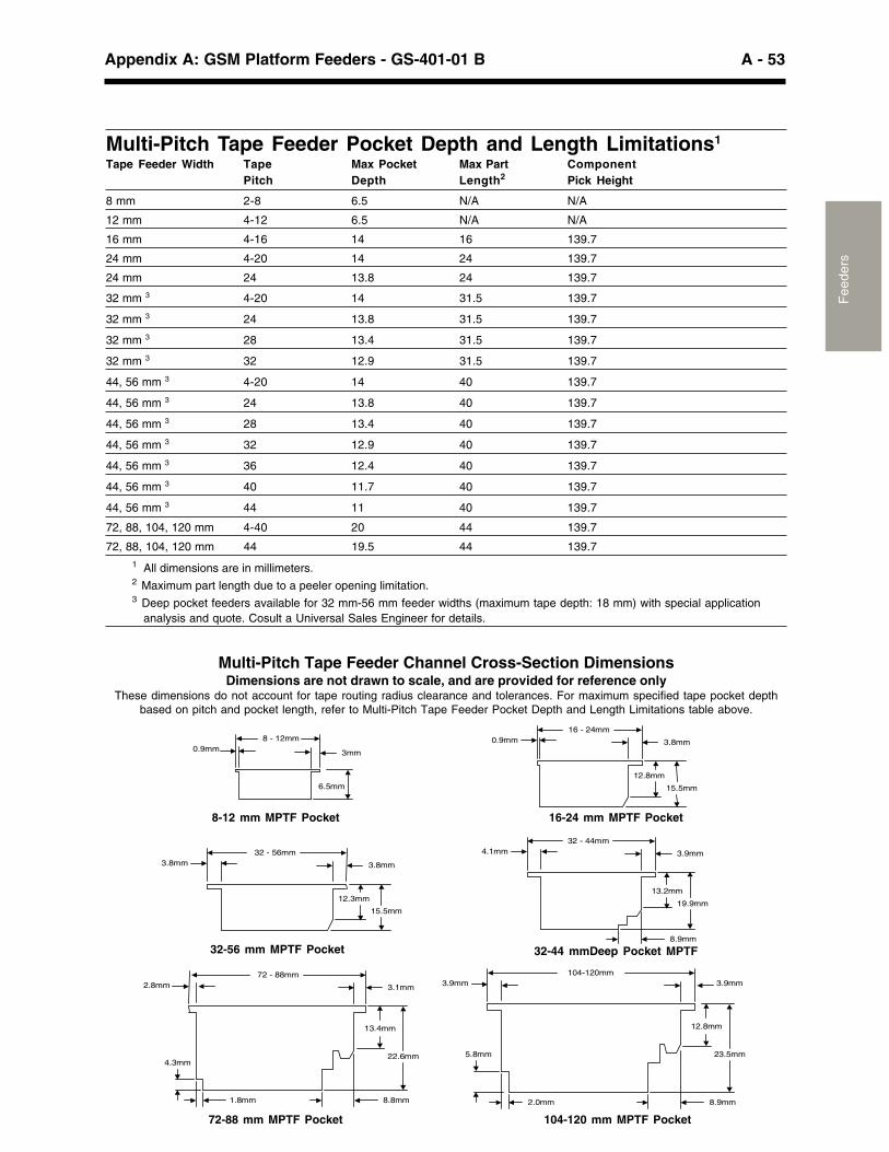
A - 53Appendix A: GSM Platform Feeders - GS-401-01 B
Fee
ders
Multi-Pitch Tape Feeder Pocket Depth and Length Limitations1
Tape Feeder Width Tape Max Pocket Max Part ComponentPitch Depth Length2 Pick Height
8 mm 2-8 6.5 N/A N/A
12 mm 4-12 6.5 N/A N/A
16 mm 4-16 14 16 139.7
24 mm 4-20 14 24 139.7
24 mm 24 13.8 24 139.7
32 mm 3 4-20 14 31.5 139.7
32 mm 3 24 13.8 31.5 139.7
32 mm 3 28 13.4 31.5 139.7
32 mm 3 32 12.9 31.5 139.7
44, 56 mm 3 4-20 14 40 139.7
44, 56 mm 3 24 13.8 40 139.7
44, 56 mm 3 28 13.4 40 139.7
44, 56 mm 3 32 12.9 40 139.7
44, 56 mm 3 36 12.4 40 139.7
44, 56 mm 3 40 11.7 40 139.7
44, 56 mm 3 44 11 40 139.7
72, 88, 104, 120 mm 4-40 20 44 139.7
72, 88, 104, 120 mm 44 19.5 44 139.71 All dimensions are in millimeters.2 Maximum part length due to a peeler opening limitation.3 Deep pocket feeders available for 32 mm-56 mm feeder widths (maximum tape depth: 18 mm) with special application analysis and quote. Cosult a Universal Sales Engineer for details.
Multi-Pitch Tape Feeder Channel Cross-Section DimensionsDimensions are not drawn to scale, and are provided for reference only
These dimensions do not account for tape routing radius clearance and tolerances. For maximum specified tape pocket depthbased on pitch and pocket length, refer to Multi-Pitch Tape Feeder Pocket Depth and Length Limitations table above.
72-88 mm MPTF Pocket
0.9mm8 - 12mm
3mm
6.5mm
12.3mm
15.5mm
3.8mm 3.8mm
32 - 56mm
12.8mm
15.5mm
0.9mm 3.8mm
16 - 24mm
13.2mm
8.9mm
19.9mm
4.1mm 3.9mm
32 - 44mm
2.8mm
4.3mm22.6mm
72 - 88mm
3.1mm
13.4mm
8.8mm1.8mm
3.9mm
5.8mm 23.5mm
104-120mm3.9mm
12.8mm
8.9mm2.0mm
104-120 mm MPTF Pocket
32-56 mm MPTF Pocket 32-44 mmDeep Pocket MPTF
8-12 mm MPTF Pocket 16-24 mm MPTF Pocket
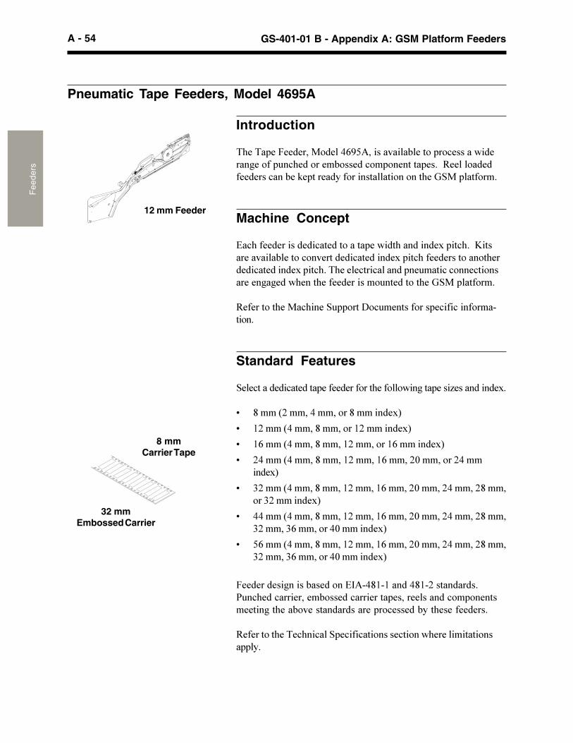
A - 54 GS-401-01 B - Appendix A: GSM Platform FeedersF
eede
rs
Pneumatic Tape Feeders, Model 4695A
Introduction
�(���� ����������������0�������������#����� ��!������'������*����� �!(��������#������!�� �������� ��+��3����������������!���#��"� ���������������������������(��%&�� ������+
Machine Concept
9�!(���������������!������������ ��'���(���������$� ��!(+��B������������#�����!�����������!���������$� ��!(����������������(������!���������$� ��!(+��(����!���!������ �� ����!�!����!�����������*�*���'(����(�������������� ���������(��%&�� ������+
3���������(����!(����& ����>�! ����������� �!���!�������������+
Standard Features
&��!��������!������� ��������������(�����'��*��� ����)�����������$+
G ������-�����������������������$�
G 6-��������������������6-��������$�
G 60�����������������6-��������60��������$�
G -������������������6-�����60�����-4��������-��������$�
G :-�����������������6-�����60�����-4�����-������-��������:-��������$�
G �������������������6-�����60�����-4�����-������-�����:-�����:0���������4��������$�
G �0�����������������6-�����60�����-4�����-������-�����:-�����:0���������4��������$�
�����������*�����#��������9,����6�6�������6�-����������+� �!(���!����������#������!��������� �������������!�� ������������*��(���#������������������ ��!������#���(�����������+
3���������(����!(��!��& �!���!���������!�����'(��������������� �+
32 mmEmbossed Carrier
8 mmCarrier Tape
12 mm Feeder
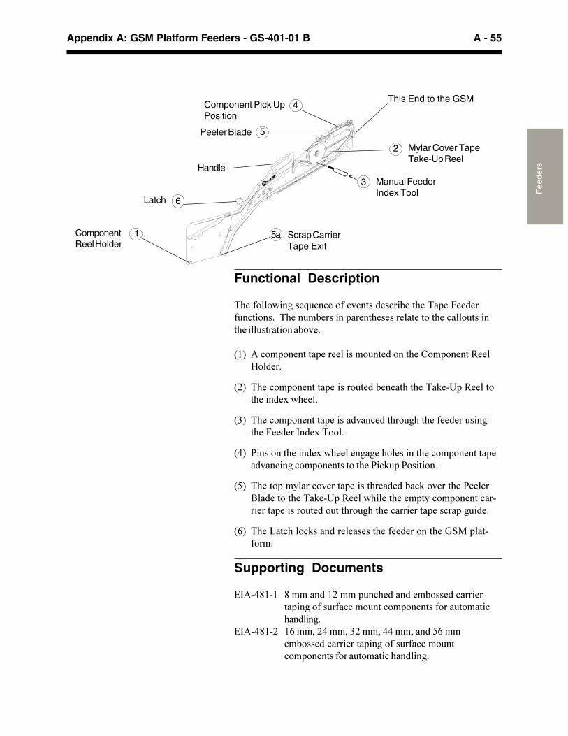
A - 55Appendix A: GSM Platform Feeders - GS-401-01 B
Fee
dersHandle
Latch
ComponentReel Holder
1 5a Scrap CarrierTape Exit
6
Component Pick UpPosition
4This End to the GSM
2 Mylar Cover TapeTake-Up Reel
5Peeler Blade
3 Manual FeederIndex Tool
Functional Description
�(�����'��*���. ��!���������������!��#���(���� ��������� �!�����+���(��� �#������� �����(���������������(��!�� ������(��� ����������#���+
�6� ��!�� �������� ����������� ���������(��8�� ������3��@����+
�-� �(��!�� �������� ������� ����#�����(��(����"��� �3������(������$�'(��+
�:� �(��!�� �������� ����������!����(�� *(��(��������� ���*�(���������,���$����+
��� ���������(������$�'(�����*�*��(��������(��!�� �������� ������!��*�!�� �����������(����!" ���������+
��� �(���� ������!������� ������(�������#�!"�������(�������2��������(����"��� �3���'(����(���� ���!�� ������!���������� ������� ����� ���(�� *(��(��!��������� ���!�� �* ���+
�0� �(��?��!(��!"���������������(�������������(��%&�� �������+
Supporting Documents
9,����6�6 ���������6-���� �!(���������#������!�������� ��*����� ���!���� ���!�� ������������ ������!(�����*+
9,����6�- 60�����-������:-�����������������0�����#������!��������� ��*����� ���!���� ��!�� ������������ ������!�(�����*+
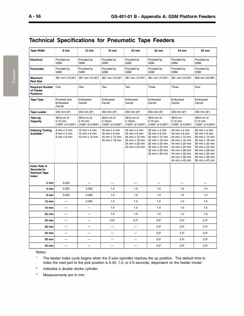
A - 56 GS-401-01 B - Appendix A: GSM Platform FeedersF
eede
rs
Technical Specifications for Pneumatic Tape Feeders
Tape Width 8 mm 12 mm 16 mm 24 mm 32 mm 44 mm 56 mm
Electrical Provided byGSM
Provided byGSM
Provided byGSM
Provided byGSM
Provided byGSM
Provided byGSM
Provided byGSM
Pneumatic Provided byGSM
Provided byGSM
Provided byGSM
Provided byGSM
Provided byGSM
Provided byGSM
Provided byGSM
MaximumReel Size
381 mm (15.00") 381 mm (15.00") 381 mm (15.00") 381 mm (15.00") 381 mm (15.00") 381 mm (15.00") 609 mm (23.98")
Required Numberof FeederPositions
One One Two Two Three Three Four
Tape Type Punched andEmbossedCarrier
EmbossedCarrier
EmbossedCarrier
EmbossedCarrier
EmbossedCarrier
EmbossedCarrier
EmbossedCarrier
Tape Leader 203 mm (8") 203 mm (8") 203 mm (8") 203 mm (8") 203 mm (8") 203 mm (8") 203 mm (8")
Take-UpCapacity
3810 cm of0.10 mm(1500" of 0.004")
3810 cm of0.10 mm(1500" of 0.004")
3810 cm of0.10mm(1500" of 0.004")
3810 cm of0.10mm(1500" of 0.004")
3810 cm of0.10 mm(1500" of 0.004")
3810 cm0.10 mm(1500" of 0.004")
3810 cm of0.10 mm(1500" of 0.004")
Indexing ToolingAvailable 3
8 mm x 2 mm8 mm x 4 mm8 mm x 8 mm
12 mm x 4 mm12 mm x 8 mm12 mm x 12 mm
16 mm x 4 mm16 mm x 8 mm16 mm x 12 mm16 mm x 16 mm
24 mm x 4 mm24 mm x 8 mm24 mm x 12 mm24 mm x 16 mm24 mm x 20 mm24 mm x 24 mm
32 mm x 4 mm32 mm x 8 mm32 mm x 12 mm32 mm x 16 mm32 mm x 20 mm32 mm x 24 mm32 mm x 28 mm32 mm x 32 mm
44 mm x 4 mm44 mm x 8 mm44 mm x 12 mm44 mm x 16 mm44 mm x 20 mm44 mm x 24 mm44 mm x 28 mm44 mm x 32 mm44 mm x 36 mm44 mm x 40 mm
56 mm x 4 mm56 mm x 8 mm56 mm x 12 mm56 mm x 16 mm56 mm x 20 mm56 mm x 24 mm56 mm x 28 mm56 mm x 32 mm56 mm x 36 mm56 mm x 40 mm
Index Rate inSeconds forSelected TapeIndex1
2 mm 0.250 — — — — — —
4 mm 0.250 0.350 1.0 1.0 1.0 1.0 1.0
8 mm 0.250 0.350 1.0 1.0 1.0 1.0 1.0
12 mm — 0.350 1.0 1.0 1.0 1.0 1.0
16 mm — — 1.0 1.0 1.0 1.0 1.0
20 mm — — 1.0 1.0 1.0 1.0 1.0
24 mm — — 2.02 2.02 2.02 2.02 2.02
28 mm — — — — 2.02 2.02 2.02
32 mm — — — — 2.02 2.02 2.02
36 mm — — — — 2.02 2.02 2.02
40 mm — — — — 2.02 2.02 2.02
Notes:1 The feeder index cycle begins when the Z-axis (spindle) reaches the up position. The default time to
index the next part to the pick position is 0.40, 1.0, or 2.0 seconds, dependent on the feeder model.2 Indicates a double stroke cylinder.3 Measurements are in mm.
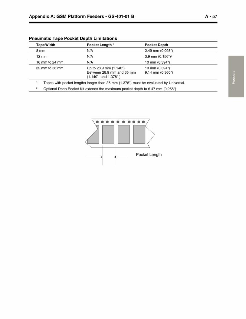
A - 57Appendix A: GSM Platform Feeders - GS-401-01 B
Fee
ders
Pneumatic Tape Pocket Depth LimitationsTape Width Pocket Length 1 Pocket Depth
8 mm N/A 2.49 mm (0.098")
12 mm N/A 3.9 mm (0.156")2
16 mm to 24 mm N/A 10 mm (0.394")
32 mm to 56 mm Up to 28.9 mm (1.140") 10 mm (0.394")Between 28.9 mm and 35 mm 9.14 mm (0.360")(1.140" and 1.378" )
1 Tapes with pocket lengths longer than 35 mm (1.378") must be evaluated by Universal.2 Optional Deep Pocket Kit extends the maximum pocket depth to 6.47 mm (0.255").
Pocket Length
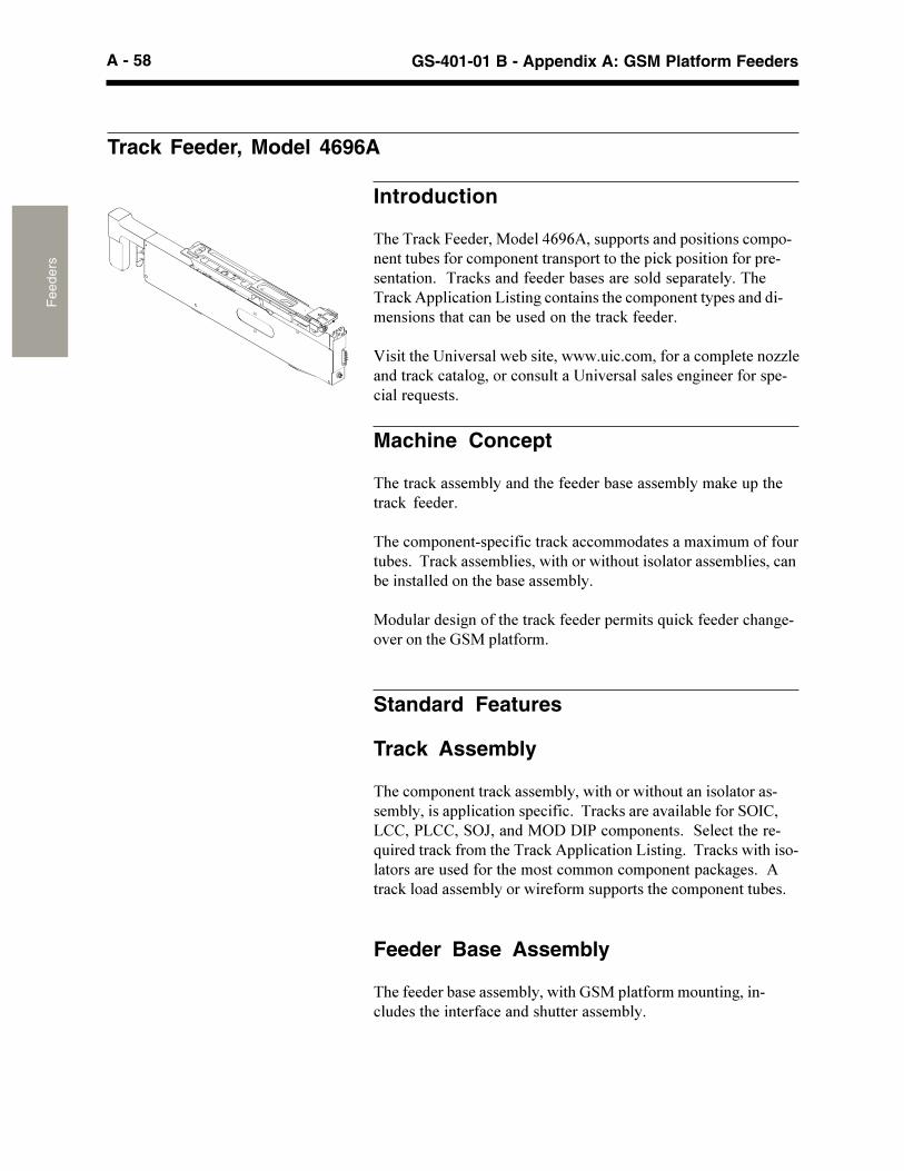
A - 58 GS-401-01 B - Appendix A: GSM Platform FeedersF
eede
rs
Track Feeder, Model 4696A
Introduction
�(�����!"���������������0�0���� ��������� ���������!�� �������� #�������!�� ����������� ��������(�� �!"� ������������ ������������+�����!"�������������#��������������� ������+��(����!"�� �!������?�����*�!���������(��!�� �������� ��������������������(���!���#�� ��������(�����!"�������+
D������(�����������'�#�������'''+ �!+!����������!�� ������))��������!"�!����*�����!��� ��������������������*����������� ��!�����. ����+
Machine Concept
�(�����!"������#�������(���������#���������#����"�� ��(����!"� ������+
�(��!�� ������� �!���!����!"��!!��������������$�� ������� �� #��+�����!"������#�����'��(����'��(� ���������������#�����!��#��������������(��#���������#�+
��� �������*������(�����!"�������� �������. �!"��������!(��*�����������(��%&�� ������+
Standard Features
Track Assembly
�(��!�� ���������!"������#���'��(����'��(� �������������������#������� �!������� �!���!+�����!"�����������#������&=,8�?88���?88��&=A�������=>�>,��!�� ������+��&��!���(�����. ��������!"�������(�����!"�� �!������?�����*+�����!"��'��(��������������� ���������(�������!������!�� ������ �!"�*��+������!"����������#�����'��������� ������(��!�� ������� #��+
Feeder Base Assembly
�(���������#���������#���'��(�%&�� ��������� ����*�����! �����(���������!�������( ����������#�+
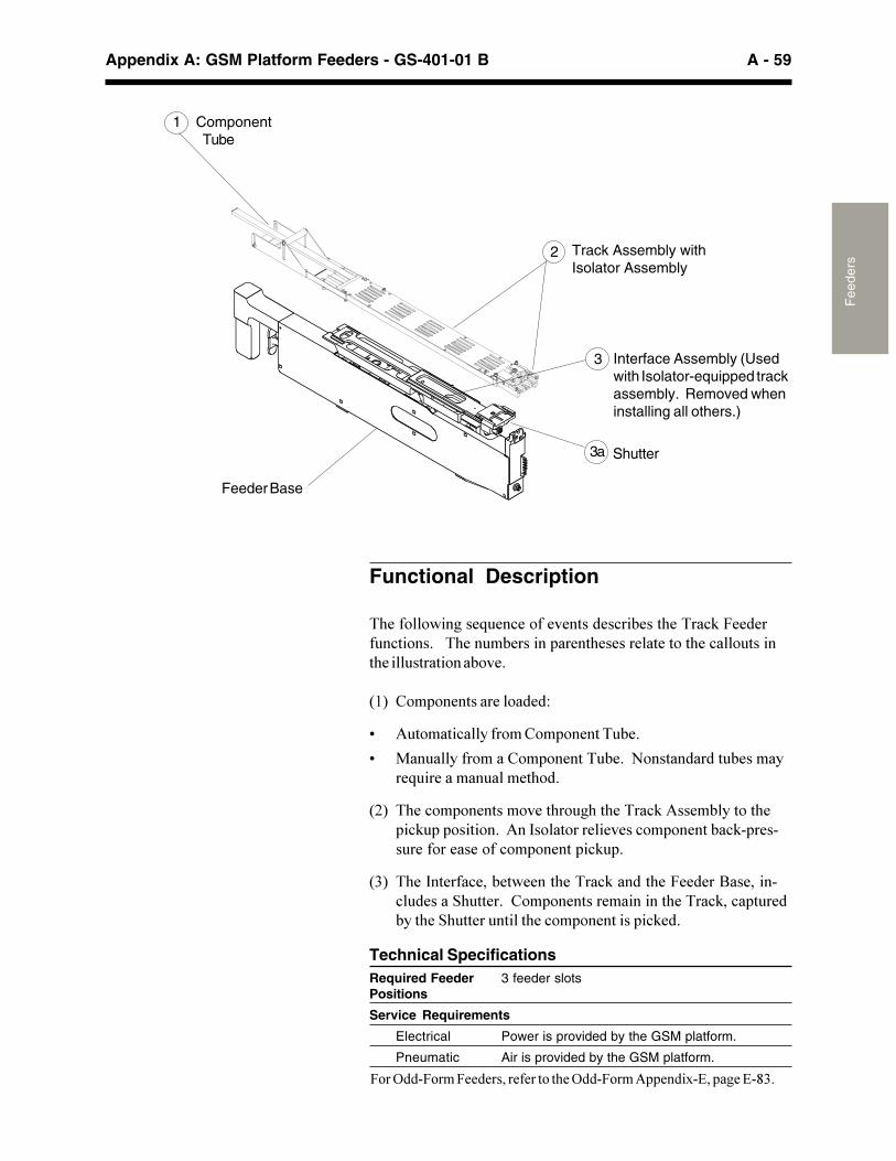
A - 59Appendix A: GSM Platform Feeders - GS-401-01 B
Fee
ders
Technical SpecificationsRequired Feeder 3 feeder slotsPositions
Service Requirements
Electrical Power is provided by the GSM platform.
Pneumatic Air is provided by the GSM platform.
Feeder Base
2 Track Assembly withIsolator Assembly
1 ComponentTube
3 Interface Assembly (Usedwith Isolator-equipped trackassembly. Removed wheninstalling all others.)
3a Shutter
Functional Description
�(�����'��*���. ��!���������������!��#����(�����!"�������� �!�����+����(��� �#������� �����(���������������(��!�� ������(��� ����������#���+
�6� 8�� ����������������;
G � ������!��������8�� ������� #�+
G ��� ����������8�� ������� #�+��F������������ #��������. ��������� �����(��+
�-� �(��!�� �������������(�� *(��(�����!"������#������(� �!" � �������+�����,���������������!�� ������#�!"� ����� ���������������!�� ������ �!" +
�:� �(��,������!���#��'�����(�����!"������(���������2��������! ������&( ����+��8�� ������������������(�����!"��!� � ���#���(��&( ����� �����(��!�� ��������� �!"��+
���������������������� �� �������������������������������
A - 60 GS-401-01 B - Appendix A: GSM Platform FeedersF
eede
rs
Stationary Matrix Tray Platform, Model 4649A
Introduction
�(��&���������������$���������������������0����������#������� ����677+�����$�::4+-�����7C�$�6:C�������$������+���(�������$����� ���������. �������� �'�������(������� �����+
Functional Description
�(�������$������� ����!�� ������#����! ���������$����������!�� ������ �!" �#���(��%&�� ������+
Technical SpecificationsMaximum 25.4 mm (1.0")Component andTray Height
Weight 11.8 kg (26 lbs.)
Required Feeder 8 feeder slotsPositions
Service None required.Requirements
Matrix Tray Pick Limitations (Available axis travel to reach Matrix Tray pockets)GSM Platform Configuration Head/Beam Feeder Bank Outbound 5" Inbound 8.5" Inbound
Standard
GSM 1 Head 1 Front 14.40" N/A N/AGSM 1 Head 1 Rear 4.15" 9.15" N/AGSM 1 Head 2 Front 4.15" N/A N/AGSM 1 Head 2 Rear 14.40" 19.40" N/AGSM 2 Head 1/Beam 1 Front N/A N/A N/AGSM 2 Head 1/Beam 1 Rear 5.24" 10.24" 13.74"GSM 2 Head 2/Beam 2 Front 5.24" N/A N/AGSM 2 Head 2/Beam 2 Rear N/A N/A N/AThis table notes the distances of Y-axis travel from the feeder interface dowel pins to the limit. When configuring therear feeder plate position, users should consider the trade-off between maximum board width, Matrix Tray picklimitations (available travel to reach Matrix Tray pockets), and machine throughput. These limitations do not apply tothe Platform Tray Feeder.
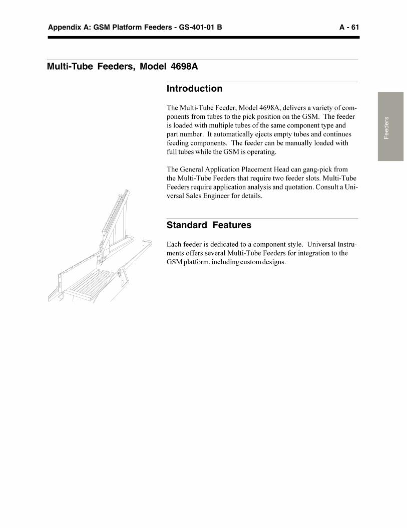
A - 61Appendix A: GSM Platform Feeders - GS-401-01 B
Fee
ders
Multi-Tube Feeders, Model 4698A
Introduction
�(��� ���� #����������������0��������������������������!��� ������������� #�������(�� �!"� ������������(��%&�+���(�����������������'��(�� �� ��� #�������(�������!�� �������� ����� ����� �#��+��,��� ������!����/�!����� ���� #�������!����� ��������*�!�� ������+���(���������!���#����� ���������'��(� �� #���'(����(��%&������ ������*+
�(��%������� �!��������!������@����!���*��*� �!"������(��� ���� #�����������(�����. �����'�������������+�� ���� #�����������. ����� �!������������������. �������+�8��� ��������������&����9�*����������������+
Standard Features
9�!(���������������!����������!�� ����������+�����������,���� ���������������������� ���� #������������������*�����������(�%&�� ����������! ���*�! ���������*��+
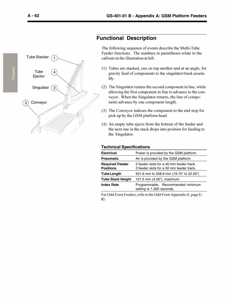
A - 62 GS-401-01 B - Appendix A: GSM Platform FeedersF
eede
rs
�(�����'��*���. ��!���������������!��#���(��� ���� #��������� �!�����+���(��� �#������� �����(���������������(�!�� �������(��� ���������������+
�6� � #����������!"������������� �����(���������������*������*���������������!�� �����������(�����* ����E���!"�������#�+
�-� �(��&��* ��������������(����!����!�� ��������������'(����'��*��(��������!�� ���������������������!������(��!��������+��1(����(��&��* �������� ������(���������!�� �������������!��#������!�� ��������*�(+
�:� �(��8������������$����(��!�� ����������(��������� ���� �!"� �#���(��%&�� �������(���+
��� ����� ���� #���/�!���������(��#����������(�������������(����$����������(�����!"���� ������� ������������������*����(���&��* ����+
2
4
1
Technical SpecificationsElectrical Power is provided by the GSM platform.
Pneumatic Air is provided by the GSM platform.
Required Feeder 2 feeder slots for a 40 mm feeder track.Positions 3 feeder slots for a 50 mm feeder track.
Tube Length 501.6 mm to 558.8 mm (19.75" to 22.00")
Tube Stack Height 101.6 mm (4.00"), maximum
Index Rate Programmable. Recommended minimumsetting is 1.300 seconds.
���������������������� �� �������������������������������
3
Functional Description
Tube Stacker
TubeEjector
Singulator
Conveyor
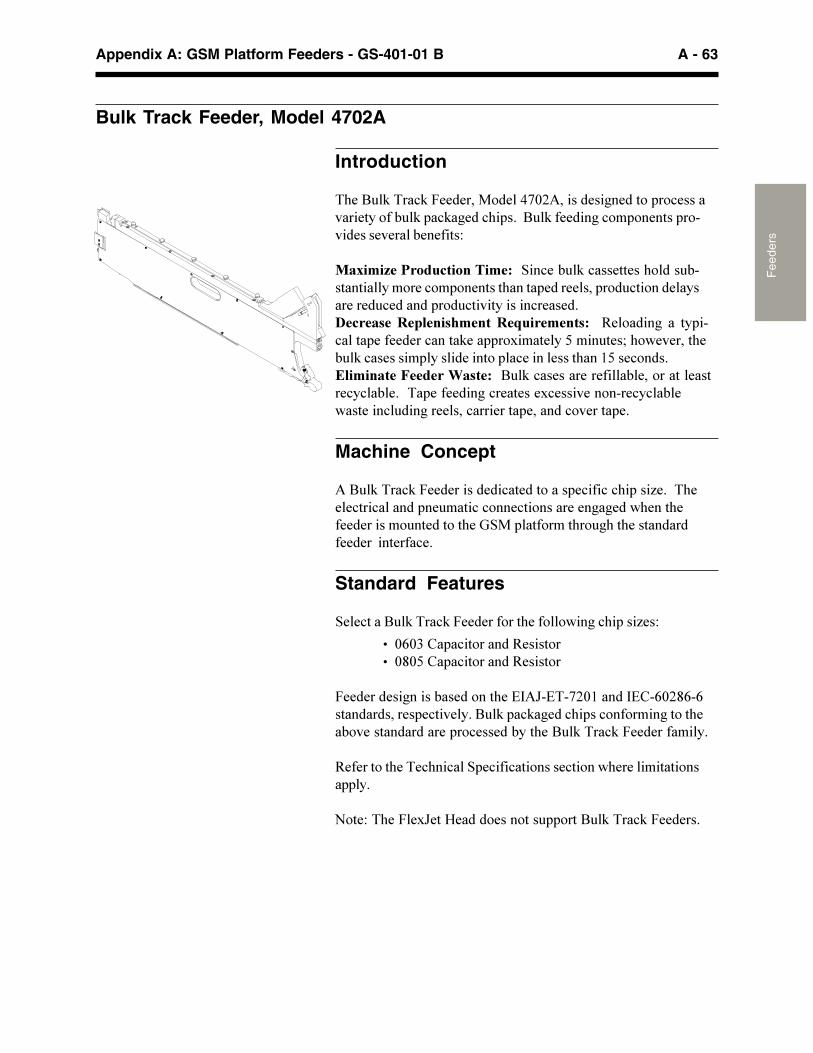
A - 63Appendix A: GSM Platform Feeders - GS-401-01 B
Fee
ders
Bulk Track Feeder, Model 4702A
Introduction
�(��2 "����!"���������������74-����������*������� ��!����������������# "� �!"�*���!(� �+��2 "�������*�!�� ������� ����������������#�������;
������������������ ������&��!��# "�!���������(���� #���������������!�� ��������(����� ��������� ��� !����������������� !������� ��� !������������!������+!�����"�� #��$���"������ #�%��������"�� �3������*� �� �� ��!���� ���������!�����"��� ��$������������ ���<�(�'�������(�# "�!�������� ������������ �!����������(���6����!����+�$���������������&�"�����2 "�!��������������#���������������!�!�#�+���� ��������*�!��������$!�������������!�!�#�'�������! ���*�������!��������� �������!������� �+
Machine Concept
��2 "����!"���������������!����������� �!���!�!(� ���)�+���(���!���!������ �� ����!�!����!������������*�*���'(����(������������� ���������(��%&�� ��������(�� *(��(����������������� �������!�+
Standard Features
&��!����2 "����!"�������������(�����'��*�!(� ���)��;
���404:�8� �!���������3����������4�4��8� �!���������3�������
�����������*�����#���������(��9,�A�9��7-46�����,98�04-�0�0�������������� �!�����+�2 "� �!"�*���!(� ��!��������*�����(��#����������������� ��!������#���(��2 "����!"�������������+
3���������(����!(��!��& �!���!���������!�����'(��������������� �+
F���;��(����$A���@�������������� ����2 "����!"��������+
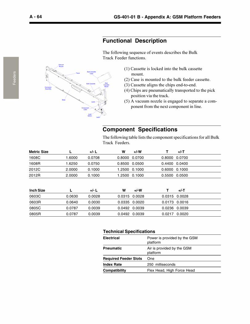
A - 64 GS-401-01 B - Appendix A: GSM Platform FeedersF
eede
rs
Technical SpecificationsElectrical Power is provided by the GSM
platform
Pneumatic Air is provided by the GSMplatform
Required Feeder Slots One
Index Rate 250 milliseconds
Compatibility Flex Head, High Force Head
Functional Description
�(�����'��*���. ��!���������������!��#����(��2 "���!"��������� �!�����+
�6��8������������!"���������(��# "�!��������������� ��+�-��8��������� ���������(��# "��������!�������+�:��8����������*����(��!(� ������������+����8(� ������ �� ����!�������� ����������(�� �!"
�������������(�����!"+��������! ����))�������*�*�������� ��������!���
������������(����$��!�� ������������+
ConnectorAssembly
VacuumNozzle
Bulk CassetteCaseTrack
Bulk Cassette
Lever
ComponentLabel
Base
LoadButton
Latch
Bulk Cassette
Mount
Metric Size L +/- L W +/-W T +/-T
1608C 1.6000 0.0708 0.8000 0.0700 0.8000 0.0700
1608R 1.6250 0.0750 0.8500 0.0500 0.4400 0.0400
2012C 2.0000 0.1000 1.2500 0.1000 0.6000 0.1000
2012R 2.0000 0.1000 1.2500 0.1000 0.5500 0.0500
Component Specifications�(�����'��*���#��������(��!�� ������� �!���!�������������2 "���!"� �������+
Inch Size L +/- L W +/-W T +/-T
0603C 0.0630 0.0028 0.0315 0.0028 0.0315 0.0028
0603R 0.0640 0.0030 0.0335 0.0020 0.0173 0.0016
0805C 0.0787 0.0039 0.0492 0.0039 0.0236 0.0039
0805R 0.0787 0.0039 0.0492 0.0039 0.0217 0.0020
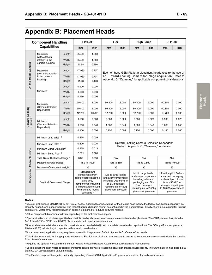
B - 65Appendix B: Placement Heads - GS-401-01 B
Pla
cem
ent
He
ad
s
Component HandlingCapabilities
FlexJet 1 Flex High Force UFP 300
mm inch mm inch mm inch mm inch
Maximum(without thetarotation in thecamera housing)
Length 25.400 1.000
Each of these GSM Platform placement heads require the use ofan Upward-Looking Camera for image acquisition. Refer toAppendix C, “Cameras,” for applicable component considerations.
Width 25.400 1.000
Height 11.68 0.460
Maximum(with theta rotationin the camerahousing)
Length 17.960 0.707
Width 17.960 0.707
Height 11.68 0.460
Minimum
Length 0.500 0.020
Width 1.000 0.040
Height 0.150 0.006
Maximum(Camera SelectionDependent)
Length 50.800 2.000 50.800 2.000 50.800 2.000 50.800 2.000
Width 50.800 2.000 50.800 2.000 50.800 2.000 50.800 2.000
Height 12.700 0.5004 12.700 0.500 12.700 0.500 12.700 0.500
Minimum(Camera SelectionDependent)
Length 0.500 0.020 0.500 0.020 0.500 0.020 0.500 0.020
Width 1.000 0.040 1.000 0.040 1.000 0.040 1.000 0.040
Height 0.150 0.006 0.150 0.006 0.150 0.006 0.150 0.006
Minimum Lead Width 5 0.228 0.009
Upward-Looking Camera Selection DependentRefer to Appendix C, “Cameras,” for details
Minimum Lead Pitch 5 0.500 0.020
Minimum Bump Diameter 5 0.335 0.013
Minimum Bump Pitch 5 0.671 0.026
Task Block Thickness Range 6 6.35 0.250 N/A N/A N/A
Placement Force Range 150 to 1,000 125 to 450 175 to 2,500 7 150 to 10,000
Maximum Component Weight 8 35 35 35 35
Practical Component Range
Standard SMcomponents from
chips to large leaded &area array
components, includinga limited range of OddForm surface mount
packages 9
Mid to large leadedand array components,including Odd Form IM
or SM packagesrequiring up to 450gplacement pressure
Mid to large leadedand array components,
including advancedpackaging and Odd
Form packagesrequiring up to 2,500gplacement pressure
Ultra-fine pitch SM andadvanced packaging,such as flips chips ordie, and Odd Form
packages requiring upto 10,000g placement
pressure
Appendix B: Placement Heads
1 Vacuum pick surface MANDATORY for FlexJet heads. Additional considerations for the FlexJet head include the lack of backlighting capability, co-planarity support, and gripper nozzles. The FlexJet nozzle changers cannot be configured in the Feeder Bank. Finally, there is no support for thin filmapplicator or wafer array feeders; however, support is planned for a future software release.2 Actual component dimensions will vary depending on the pick tolerance applied.3 Special situations exist where specified constraints can be alleviated to accommodate non-standard applications. The GSM platform has placed a146.1 mm (5.75") x 12.95 mm (0.510") SM connector with special considerations.4 Special situations exist where specified constraints can be alleviated to accommodate non-standard applications. The GSM platform has placed a25.4 mm (1.0") tall electrolytic capacitor with special considerations.5 Some component applications may require an upward looking camera. Refer to Appendix C: “Cameras” for details.6 This thickness range is for imaging parts in the same FlexJet task block and is necessary to ensure all components are centered within the specifiedfocal plane of the camera.7 Requires the optional Pressure Enhancement Kit and Pressure Readout Assembly for calibration and maintenance.8 Special situations exist where specified constraints can be alleviated to accommodate non-standard applications. The GSM platform has placed a 56gram CCGA using a specific vacuum nozzle.
9 The FlexJet component range is continually expanding. Consult GSM Applications Engineer for a review of specific components.
Notes:
On-
the-
Hea
d C
amer
a 2U
pwar
d-Lo
okin
gC
amer
a 3
Com
pone
nt C
hara
cter
istic
s
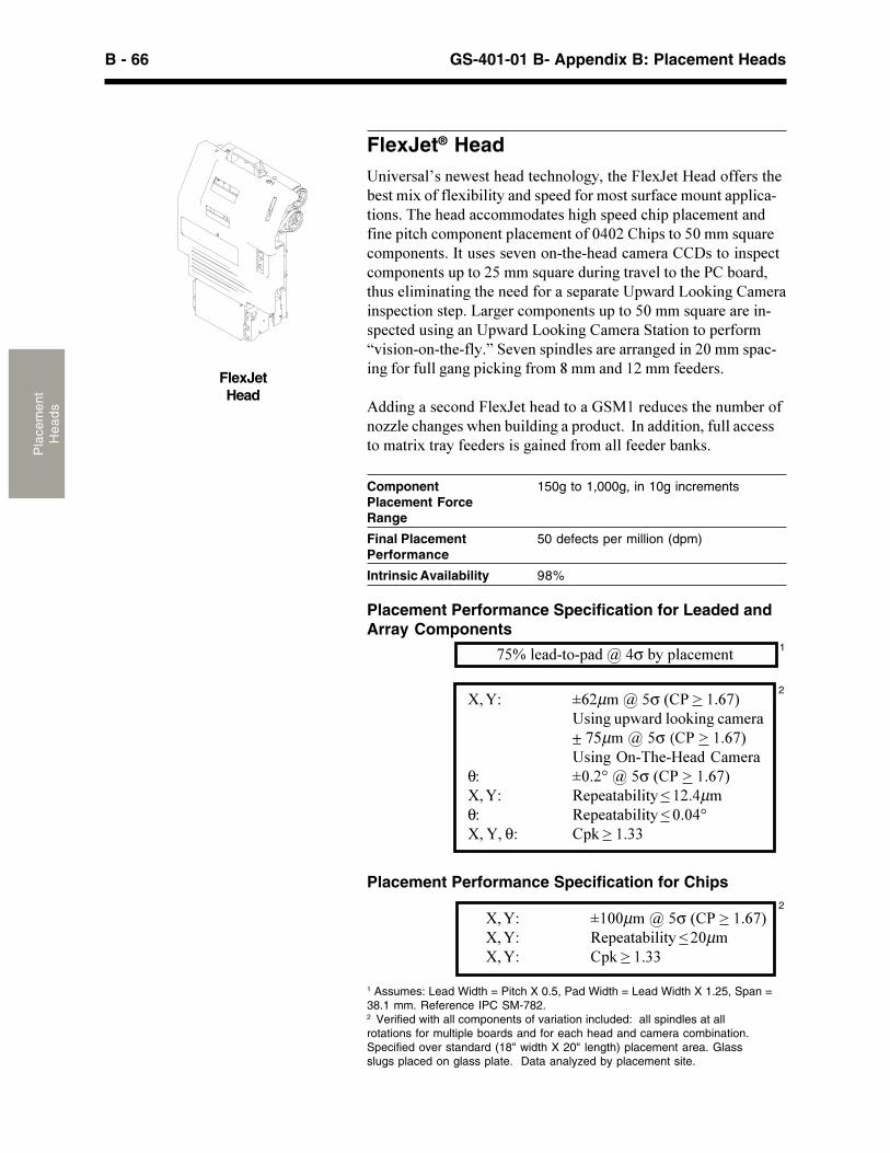
B - 66 GS-401-01 B- Appendix B: Placement HeadsP
lace
men
tH
ea
ds
����� ���µ���σ�� ����������������������� !����"�#��+ 75µ���σ ( ���������������$�%&'#%(#��� �#��
θ� �)��*���σ�� �������������� +#�#�,�-���,.�/����0µθ� +#�#�,�-���,.�/�)�)0*������θ� �!�����11
2
2
1 Assumes: Lead Width = Pitch X 0.5, Pad Width = Lead Width X 1.25, Span =38.1 mm. Reference IPC SM-782.2 Verified with all components of variation included: all spindles at allrotations for multiple boards and for each head and camera combination.Specified over standard (18" width X 20" length) placement area. Glassslugs placed on glass plate. Data analyzed by placement site.
Placement Performance Specification for Chips
����� ��))µ���σ�� �������������� +#�#�,�-���,.�/��)µ����� �!�����11
Component 150g to 1,000g, in 10g incrementsPlacement ForceRange
Final Placement 50 defects per million (dpm)Performance
Intrinsic Availability 98%
FlexJetHead
���2#����3���#�#�,�'#���,#"'� � �.��,'#�4�#56#,�(#��� 77#���,'#-#�,��5� 7�7�#5�-���,.�������##��7 �� �,����7�"#� ��,������"�%,� ����&'#�'#����"" ��,#��'��'���##��"'������"##�,����7��#���,"'�" � �#�,����"##�,� 7�)0)�� '����, ��)���8���#" � �#�,���9,���#���#2#�� �%,'#%'#���"�#��� :��, �����#"," � �#�,�����, ������8���#��������,��2#��, �,'#�� �- ����,'���#�����,����,'#��##��7 �����#����,#��������; !���� �#������#",� ���,#���;���#��" � �#�,�����, ��)���8���#���#���%��#",#������������������; !���� �#���<,�,� ��, ��#�7 �=2��� �% �%,'#%7�.�>�<#2#��������#����#�������#������)�����"%����7 ��7�����������"!����7� �?����������7##�#���
@���������#" ���4�#56#,�'#���, ���A<B���#��"#��,'#���-#�� 7� CC�#�"'���#���'#��-������������ ��",���9������,� ���7�����""#��, ��,��5�,��.�7##�#����������#��7� �����7##�#��-��!��
FlexJet® Head
Placement Performance Specification for Leaded andArray Components
��D��#��%, %�����0σ�-.����"##�, 1
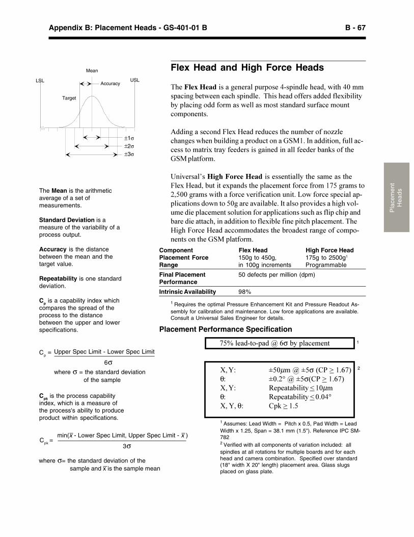
B - 67Appendix B: Placement Heads - GS-401-01 B
Pla
cem
ent
He
ad
sThe Mean is the arithmeticaverage of a set ofmeasurements.
Standard Deviation is ameasure of the variability of aprocess output.
Accuracy is the distancebetween the mean and thetarget value.
Repeatability is one standarddeviation.
Cp is a capability index whichcompares the spread of theprocess to the distancebetween the upper and lowerspecifications.
Cpk is the process capabilityindex, which is a measure ofthe process's ability to produceproduct within specifications.
��D��#��%, %������σ�-.����"##�,
����� ��)µ����σ�� ���������θ� �)��*����σ� �������������� +#�#�,�-���,.�/��)µθ� +#�#�,�-���,.�/�)�)0*������θ� �!������
1 Assumes: Lead Width = Pitch x 0.5, Pad Width = LeadWidth x 1.25, Span = 38.1 mm (1.5"). Reference IPC SM-7822 Verified with all components of variation included: allspindles at all rotations for multiple boards and for eachhead and camera combination. Specified over standard(18" width X 20" length) placement area. Glass slugsplaced on glass plate.
Cp= Upper Spec Limit - Lower Spec Limit
6σwhere σ = the standard deviation
of the sample
Cpk=
min(x - Lower Spec Limit, Upper Spec Limit - x )
3σ
where σ= the standard deviation of the sample and x is the sample mean
Flex Head and High Force Heads
&'#�����������������#�#�������� �#�0%������#�'#������,'�0)����"����-#,�##��#�"'�������#���&'���'#��� 77#������#��7�#5�-���,.-.����"���� ���7 ������#������ �,��,����������7�"#� ��," � �#�,��
@���������#" ���4�#5�(#����#��"#��,'#���-#�� 7�� CC�#"'���#���'#��-������������ ��",� ����A<B���9������,� ���7�����"%"#���, ��,��5�,��.�7##�#����������#���������7##�#��-��!�� 7�,'#A<B����,7 ��
���2#����3������� �����������#��#�,����.�,'#���#����,'#4�#5�(#����-�,��,�#5������,'#����"##�,�7 �"#�7� ����������, ���))��������,'���7 �"#�2#��7�"�,� �����,��; ��7 �"#���#"������%���"�,� ���� ���, ��)����#��2����-�#��9,���� ��� 2��#����'��'�2 �%�#���#����"##�,�� ��,� ��7 �������"�,� �����"'����7����"'������-��#���#��,,�"'���������,� ��, �7�#5�-�#�7��#���,"'����"##�,��&'#(��'�4 �"#�(#����"" ��,#��,'#�-� ��#�,�����#� 7�" � %�#�,�� ��,'#�A<B����,7 ��
Placement Performance Specification
1
Component Flex Head High Force HeadPlacement Force 150g to 450g, 175g to 2500g1
Range in 100g increments Programmable
Final Placement 50 defects per million (dpm)Performance
Intrinsic Availability 98%
1 Requires the optimal Pressure Enhancement Kit and Pressure Readout As-sembly for calibration and maintenance. Low force applications are available.Consult a Universal Sales Engineer for details.
LSL USL
Target
Mean
Accuracy
±1σ±2σ±3σ
2
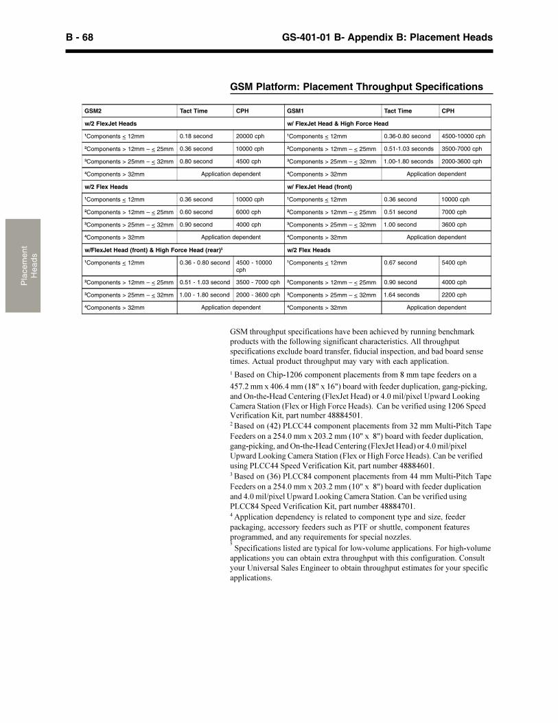
B - 68 GS-401-01 B- Appendix B: Placement HeadsP
lace
men
tH
ea
ds
�������������� ��������������� �� ������ � ������������ ���������������������� ���������������������������� ���������������������� ������������ ���� ������������� ��������������� ���������������������� �� ��� �������������������������������������� ��������������������� ����� ���!"#$%������� ������� � ���������&������� �� � �������
'()�#������'$%�'����*"&+���"%+,������������� � ����������������!�����������-�!�� !. ��� �� ����*/� �0 ��. ��,����'�$����1��� ��2������3����� �� �����������*/� �����.���/��� �. ���,��� ���� �� ���� ������"#$%��� �4 �����������5������������ ��'&&&'($"������ �����*'#,�63 ''������� ������� � ���������7#��������!6�����8�� / � ��������#('�$������#$7�#����*"$+����&+,������������� � ���������������!������������-�!�� !. ��� �� ����*/� �0 ��. ��,����'�$����1��� �2������3������ �� �����������*/� �����.���/��� �. ���,�� ���� �� ���� �����63 ''��� ��4 �����������5������������ ��'&&&'%$"������ �����*7%,�63 &'������� ������� � ���������''��������!6�����8�� / � ��������#('�$������#$7�#����*"$+����&+,������������� � ����������������'�$����1��� ��2������3������ �� ������������ ���� �� ���� �����63 &'��� ��4 �����������5������������ ��'&&&')$"���������������� � �� �������� ��� ����������� ������ �������9 ��� � ������������� ������� � ����������68/��������� �������� ���� ��� �������� ������������ :�� � ���������� �������99� ������ ���������������� ���� ����������������!���� ���������������/������!���� ��������������������������� ������������������������������������ ���������2��� �������� ��;��� �������������������� ������ ������������ ������������������
GSM Platform: Placement Throughput Specifications
GSM2 Tact Time CPH GSM1 Tact Time CPH
w/2 FlexJet Heads w/ FlexJet Head & High Force Head
1Components < 12mm 0.18 second 20000 cph 1Components < 12mm 0.36-0.80 second 4500-10000 cph
2Components > 12mm – < 25mm 0.36 second 10000 cph 2Components > 12mm – < 25mm 0.51-1.03 seconds 3500-7000 cph
3Components > 25mm – < 32mm 0.80 second 4500 cph 3Components > 25mm – < 32mm 1.00-1.80 seconds 2000-3600 cph
4Components > 32mm Application dependent 4Components > 32mm Application dependent
w/2 Flex Heads w/ FlexJet Head (front)
1Components < 12mm 0.36 second 10000 cph 1Components < 12mm 0.36 second 10000 cph
2Components > 12mm – < 25mm 0.60 second 6000 cph 2Components > 12mm – < 25mm 0.51 second 7000 cph
3Components > 25mm – < 32mm 0.90 second 4000 cph 3Components > 25mm – < 32mm 1.00 second 3600 cph
4Components > 32mm Application dependent 4Components > 32mm Application dependent
w/FlexJet Head (front) & High Force Head (rear)5 w/2 Flex Heads
1Components < 12mm 0.36 - 0.80 second 4500 - 10000cph
1Components < 12mm 0.67 second 5400 cph
2Components > 12mm – < 25mm 0.51 - 1.03 second 3500 - 7000 cph 2Components > 12mm – < 25mm 0.90 second 4000 cph
3Components > 25mm – < 32mm 1.00 - 1.80 second 2000 - 3600 cph 3Components > 25mm – < 32mm 1.64 seconds 2200 cph
4Components > 32mm Application dependent 4Components > 32mm Application dependent
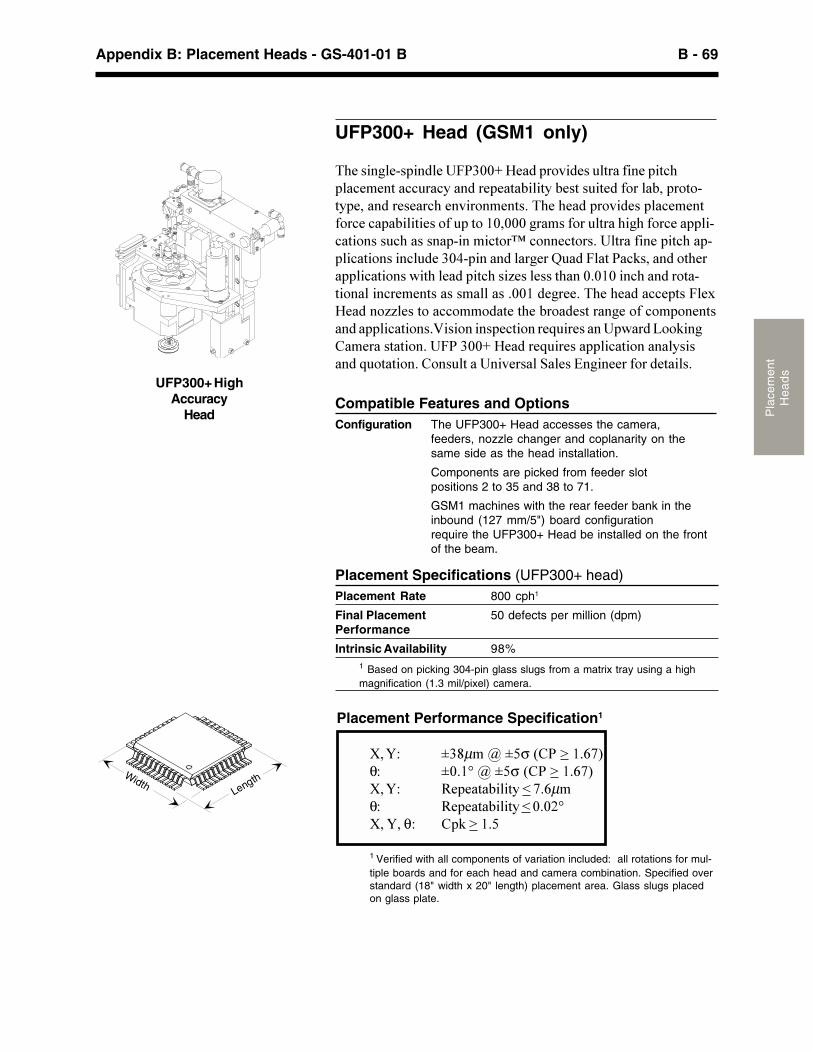
B - 69Appendix B: Placement Heads - GS-401-01 B
Pla
cem
ent
He
ad
s
UFP300+ Head (GSM1 only)
&'#������#%������#��4�1))E�(#����� 2��#����,���7��#���,"'���"##�,��""���".������#�#�,�-���,.�-#�,����,#��7 ����-���� , %,.�#�������#�#��"'�#�2�� �#�,���&'#�'#����� 2��#�����"##�,7 �"#�"���-���,�#�� 7����, ��)�)))������7 ����,���'��'�7 �"#������%"�,� �����"'��������%����", �F�" ��#", ������,���7��#���,"'���%���"�,� �����"���#�1)0%������������#��G����4��,���"!������� ,'#������"�,� �����,'��#�����,"'���C#���#���,'���)�)�)���"'������ ,�%,� ������"�##�,��������������))���#��##��&'#�'#����""#�,��4�#5(#���� CC�#��, ��"" ��,#�,'#�-� ��#�,�����#� 7�" � �#�,����������"�,� ���H��� ������#",� ���#8���#������������; !��� �#����,�,� ����4��1))E�(#����#8���#�������"�,� ������.�������8� ,�,� ��� ����,������2#�����<��#��I����##��7 ���#,�����
Compatible Features and OptionsConfiguration The UFP300+ Head accesses the camera,
feeders, nozzle changer and coplanarity on thesame side as the head installation.
Components are picked from feeder slotpositions 2 to 35 and 38 to 71.
UFP300+ HighAccuracy
Head
Placement Specifications (UFP300+ head)Placement Rate 800 cph1
Final Placement 50 defects per million (dpm)Performance
Intrinsic Availability 98%1 Based on picking 304-pin glass slugs from a matrix tray using a highmagnification (1.3 mil/pixel) camera.
����� �1?µ����σ�� ���������θ� �)��*����σ�� �������������� +#�#�,�-���,.�/����µθ� +#�#�,�-���,.�/�)�)�*����� θ� �!������
1 Verified with all components of variation included: all rotations for mul-tiple boards and for each head and camera combination. Specified overstandard (18" width x 20" length) placement area. Glass slugs placedon glass plate.
Placement Performance Specification1
GSM1 machines with the rear feeder bank in theinbound (127 mm/5") board configurationrequire the UFP300+ Head be installed on the frontof the beam.
X YWidth
Length
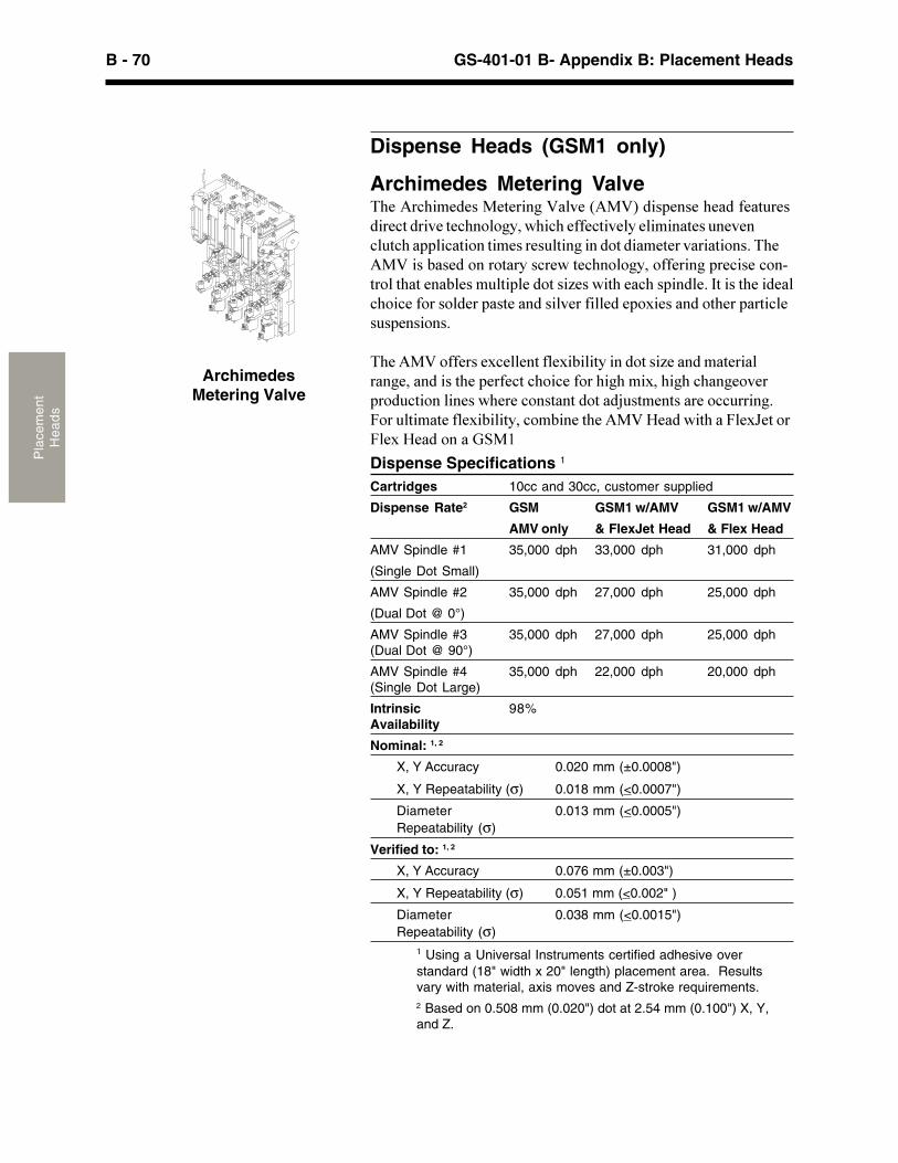
B - 70 GS-401-01 B- Appendix B: Placement HeadsP
lace
men
tH
ea
ds
Dispense Heads (GSM1 only)
ArchimedesMetering Valve
Archimedes Metering Valve&'#�@�"'�#�#��B#,#�����H��2#��@BH������#��#�'#���7#�,��#����#",����2#�,#"'� � �.���'�"'�#77#",�2#�.�#�����,#����#2#�"��,"'������"�,� ��,�#���#���,�������� ,����#,#��2����,� ����&'#@BH����-��#�� ��� ,��.��"�#��,#"'� � �.�� 77#�������#"��#�" �%,� ��,'�,�#��-�#����,���#�� ,���C#����,'�#�"'�������#��9,����,'#���#��"' �"#�7 ��� ��#�����,#��������2#��7���#��#� 5�#������ ,'#�����,�"�#����#��� ���
&'#�@BH� 77#���#5"#��#�,�7�#5�-���,.����� ,���C#������,#��������#���������,'#��#�7#",�"' �"#�7 ��'��'��5��'��'�"'���# 2#��� ��",� �����#���'#�#�" ��,��,�� ,���J��,#�,����#� ""�������4 ����,��,#�7�#5�-���,.��" -��#�,'#�@BH�(#�����,'���4�#56#,� �4�#5�(#��� ����A<B�
Dispense Specifications 1
Cartridges 10cc and 30cc, customer supplied
Dispense Rate2 GSM GSM1 w/AMV GSM1 w/AMV
AMV only & FlexJet Head & Flex Head
AMV Spindle #1 35,000 dph 33,000 dph 31,000 dph
(Single Dot Small)
AMV Spindle #2 35,000 dph 27,000 dph 25,000 dph
(Dual Dot @ 0°)
AMV Spindle #3 35,000 dph 27,000 dph 25,000 dph(Dual Dot @ 90°)
AMV Spindle #4 35,000 dph 22,000 dph 20,000 dph(Single Dot Large)
Intrinsic 98%Availability
Nominal: 1, 2
X, Y Accuracy 0.020 mm (±0.0008")
X, Y Repeatability (σ) 0.018 mm (<0.0007")
Diameter 0.013 mm (<0.0005")Repeatability (σ)
Verified to: 1, 2
X, Y Accuracy 0.076 mm (±0.003")
X, Y Repeatability (σ) 0.051 mm (<0.002" )
Diameter 0.038 mm (<0.0015")Repeatability (σ)
1 Using a Universal Instruments certified adhesive overstandard (18" width x 20" length) placement area. Resultsvary with material, axis moves and Z-stroke requirements.2 Based on 0.508 mm (0.020") dot at 2.54 mm (0.100") X, Y,and Z.
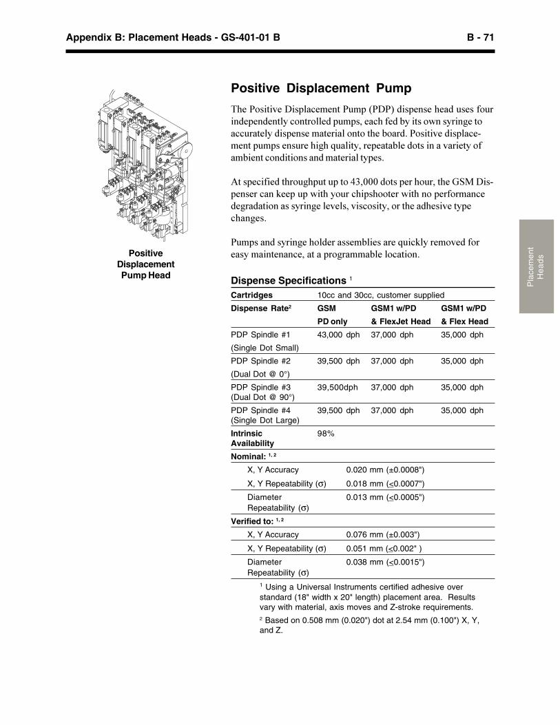
B - 71Appendix B: Placement Heads - GS-401-01 B
Pla
cem
ent
He
ad
s
Positive Displacement Pump
&'#�� ��,�2#�:�����"##�,�������:�������#��#�'#�����#��7 �����#�#��#�,�.�" �,� ��#��������#�"'�7#��-.��,�� ����.����#�, �""���,#�.�����#��#��,#����� �, �,'#�- ������ ��,�2#�������"#%#�,������#����#�'��'�8����,.���#�#�,�-�#�� ,�������2���#,.� 7�-�#�,�" ���,� ��������,#�����,.�#��
@,���#"�7�#��,'� ��'��,����, �01�)))�� ,���#��' ����,'#�A<B�:��%�#��#��"���!##�������,'�. ���"'���' ,#����,'�� ��#�7 ���"#�#�����,� ������.����#��#2#����2��" ��,.�� ��,'#���'#��2#�,.�#"'���#��
����������.����#�' ��#�����#-��#����#�8��"!�.��# 2#��7 �#��.����,#���"#���,����� ����-�#�� "�,� ��Positive
DisplacementPump Head Dispense Specifications 1
Cartridges 10cc and 30cc, customer supplied
Dispense Rate2 GSM GSM1 w/PD GSM1 w/PD
PD only & FlexJet Head & Flex Head
PDP Spindle #1 43,000 dph 37,000 dph 35,000 dph
(Single Dot Small)
PDP Spindle #2 39,500 dph 37,000 dph 35,000 dph
(Dual Dot @ 0°)
PDP Spindle #3 39,500dph 37,000 dph 35,000 dph(Dual Dot @ 90°)
PDP Spindle #4 39,500 dph 37,000 dph 35,000 dph(Single Dot Large)
Intrinsic 98%Availability
Nominal: 1, 2
X, Y Accuracy 0.020 mm (±0.0008")
X, Y Repeatability (σ) 0.018 mm (<0.0007")
Diameter 0.013 mm (<0.0005")Repeatability (σ)
Verified to: 1, 2
X, Y Accuracy 0.076 mm (±0.003")
X, Y Repeatability (σ) 0.051 mm (<0.002" )
Diameter 0.038 mm (<0.0015")Repeatability (σ)
1 Using a Universal Instruments certified adhesive overstandard (18" width x 20" length) placement area. Resultsvary with material, axis moves and Z-stroke requirements.2 Based on 0.508 mm (0.020") dot at 2.54 mm (0.100") X, Y,and Z.
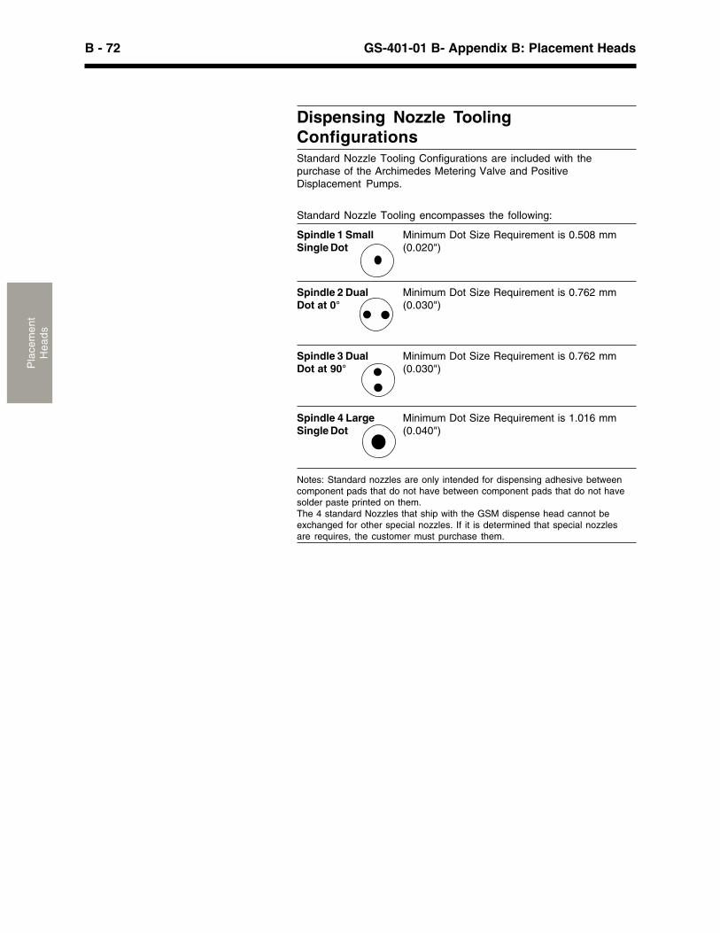
B - 72 GS-401-01 B- Appendix B: Placement HeadsP
lace
men
tH
ea
ds
Dispensing Nozzle ToolingConfigurationsStandard Nozzle Tooling Configurations are included with thepurchase of the Archimedes Metering Valve and PositiveDisplacement Pumps.
Standard Nozzle Tooling encompasses the following:
Spindle 1 Small Minimum Dot Size Requirement is 0.508 mmSingle Dot (0.020")
Spindle 2 Dual Minimum Dot Size Requirement is 0.762 mmDot at 0° (0.030")
Spindle 3 Dual Minimum Dot Size Requirement is 0.762 mmDot at 90° (0.030")
Spindle 4 Large Minimum Dot Size Requirement is 1.016 mmSingle Dot (0.040")
Notes: Standard nozzles are only intended for dispensing adhesive betweencomponent pads that do not have between component pads that do not havesolder paste printed on them.The 4 standard Nozzles that ship with the GSM dispense head cannot beexchanged for other special nozzles. If it is determined that special nozzlesare requires, the customer must purchase them.
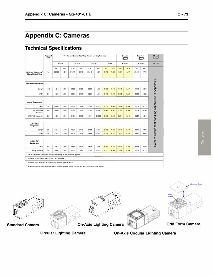
C - 73Appendix C: Cameras - GS-401-01 B
Cam
eras
Appendix C: Cameras
Technical Specifications
Circular Lighting Camera
LensCover
Camera Cover
Odd Form CameraStandard Camera On-Axis Lighting Camera
On-Axis Circular Lighting Camera
RequiredPixels
Circular and Standard Lighting Upward-Looking Cameras On-AxisLightingCamera
Odd FormLightingCamera
FlexJetOptics1
4.0 mpp 3.0 mpp 2.6 mpp 1.0 mpp 4.0 mpp 4.0 mpp 2.6 mpp
mm inch mm inch mm inch mm inch mm inch mm inch
Maximum Component2
(Single Field of View)n\a 33.358 1.313 24.067 0.948 20.348 0.801 8.270 0.326 33.358 1.313 20.193 0.795
Leadless Components
Length 10.0 1.016 0.040 0.762 0.030 0.660 0.026 0.330 0.013 1.016 0.040 1.016 0.040
Width 5.0 0.508 0.020 0.381 0.015 0.330 0.013 0.165 0.007 0.508 0.020 0.508 0.020
Leaded Components
Pitch3 4.0 0.406 0.016 0.305 0.012 0.264 0.010 0.132 0.005 .0406 0.016 0.406 0.016
Width-WithoutInspection
2.0 0.203 0.008 0.152 0.006 0.132 0.005 0.066 0.003 0.203 0.008 0.203 0.008
Width-With Inspection 2.5 0.254 0.010 0.191 0.008 0.1651 0.0065 0.083 0.003 0.254 0.010 0.254 0.010
Multi-PatternComponents
Length 25 2.540 0.100 1.905 0.075 1.651 0.065 0.826 0.033 2.540 0.100 2.540 0.100
Width 25 2.540 0.100 1.905 0.075 1.651 0.065 0.826 0.033 2.540 0.100 2.540 0.100
BGA & C44
Components
Pitch 8.0 0.813 0.032 0.610 0.024 0.528 0.021 0.264 0.010 0.813 0.032 0.813 0.032
Bump Diameter 4.0 0.406 0.016 0.305 0.012 0.264 0.010 0.132 0.005 0.406 0.016 0.406 0.016
1 Actual component dimensions will vary depending on pick tolerance applied.
2 Assumes a default ±1.905mm (0.075") pick tolerance.
3 Assumes a 2.0 pixel minimum separation distance between leads.
4 Maximum number of bumps is 3,000 with the ESI 630 vision system, and 4,000 with the ESI 640 vision system.
Ref
er t
o co
mpo
nent
han
dlin
g ca
pabi
litie
s in
App
endi
x B

C - 74 GS-401-01 B Appendix C: CamerasC
amer
as
This page intentionally left blank.
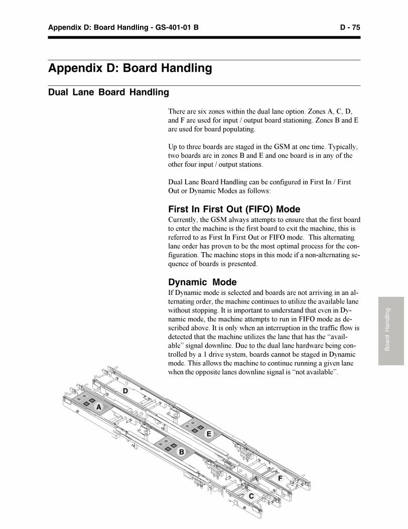
D - 75Appendix D: Board Handling - GS-401-01 B
Boa
rd H
andl
ing
Appendix D: Board Handling
Dual Lane Board Handling
������������������ �����������������������������������������������������������������������������������������������������������������������������������������
������������������������������������!"#����������$����%��&���%�� ���������������������������������������������������%������������������������������������������
�����'����������(��������&������&�������������������)���������*�������%��$�&�#������������� �+
First In First Out (FIFO) Mode��������%������!"#��� �%������$�����������������������������������������������$�&�����������������������������������$�&����������������������������������)��������*�������)�*�$����������������������������������������,�������������$��������$������&������������&��-����������������$�&�������������������$������������-��������������-.���&�������������������������
Dynamic Mode)���%��$�&�$�����������&���������������������������,������������-���������������������$�&�����&������������������������,������������ �����������������)������$����������������������������,�������%-��$�&�$���������$�&���������$���������������)�*�$���������-�&���������,���)��������%� ���������������������������������&���� �������&�������������$�&�����������������������������������/�,���-����0���������� �������������������������������� ����������&��-���������%���1����,���%���$���������&��������������������%��$�&$�������������� ������$�&��������&��������������������,������� ������������������������� ����������������/�����,�������0�
A
B
C
D
E
F
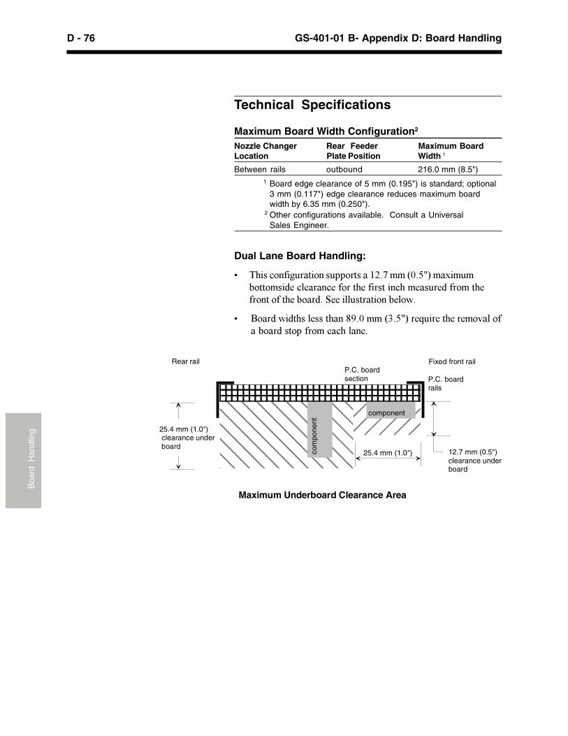
D - 76 GS-401-01 B- Appendix D: Board HandlingB
oard
Han
dlin
g
Technical Specifications
Maximum Board Width Configuration2
Nozzle Changer Rear Feeder Maximum BoardLocation Plate Position Width 1
Between rails outbound 216.0 mm (8.5")1 Board edge clearance of 5 mm (0.195") is standard; optional
3 mm (0.117") edge clearance reduces maximum boardwidth by 6.35 mm (0.250").
2 Other configurations available. Consult a UniversalSales Engineer.
Dual Lane Board Handling:
2 �����&������������������������13�4�$$�56�789�$��$�$�����$�����&������&������������������&��$�����������$������������������������"�������������������� �
2 ������ ����������������:;�6�$$�5<�789���.�����������$�,���������������������$���&�������
Fixed front railRear rail
12.7 mm (0.5")clearance under board
P.C. board section
Maximum Underboard Clearance Area
component
com
pone
nt
25.4 mm (1.0")
25.4 mm (1.0") clearance under board
P.C. board rails

E - 77Appendix E: Odd Form Assembly - GS-401-01 B
Odd
For
m A
ssem
bly
Appendix E: Odd Form Assembly Capabilities
Introduction
�������������������� ������������������������������������������������������������������������������������������������������������������������������������������������������������������������������������������������������������������������������ ������
��������������������������������������������������������������������������!��������"���������������#����������������$�������������������������������������������������������������������������������������������������$������������������������%������������������������������������������������������������������������������������������������������
Applications
�����&�������������������������������������������� ��������������'������������������������������������������������������ ������������(���������������������� ����������������������������������������������������������������� �������)��������!���������������*�������������������
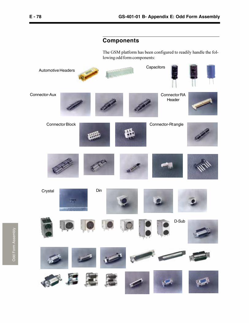
E - 78 GS-401-01 B- Appendix E: Odd Form AssemblyO
dd F
orm
Ass
embl
y
Components
���� �������������������������������������������������������������������������������+
D-Sub
DinCrystal
Connector-Rt angleConnector Block
Connector-Aux Connector RAHeader
CapacitorsAutomotive Headers
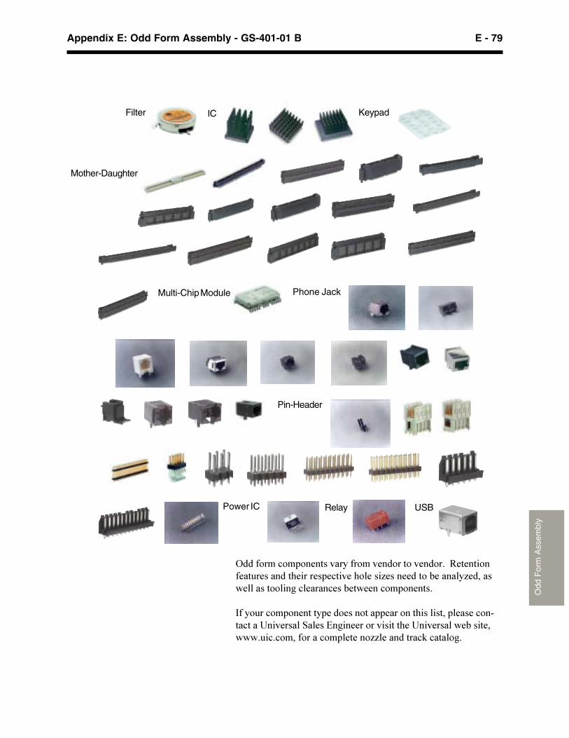
E - 79Appendix E: Odd Form Assembly - GS-401-01 B
Odd
For
m A
ssem
bly
(����������������������������������������������,����������������������������������������-�����������������-������������������������������������������������
'���������������������������������������������������������������!���������������*�������������������!���������������������������������������������--����������$��������
USBRelayPower IC
Pin-Header
Phone JackMulti-Chip Module
Mother-Daughter
KeypadICFilter
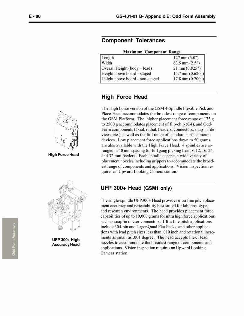
E - 80 GS-401-01 B- Appendix E: Odd Form AssemblyO
dd F
orm
Ass
embl
y
�������������������!./0112�3���������������������������������������������������������������������������������������������������������������������������������������������������������������������41�111������������������������������������������������������������������������!���������������������������������015����������������6����.���/��$�����������������������������������������-�������������141�������������������������������������������114��������������������������.����3�����--���������������������������������������������������������������7������������������ ���������!������8��$���)������������
Component Tolerances
�������� ����� � �����8���� 49:����;<�1=>?��� @0�<����;9�<=>(�������3�����;����2�����> 94����;1�A9<=>3���������������������� 4<�:����;1�@91=>3�������������������������� 4:�A����;1�:11=>
High Force Head
����3����.������������������� ���5���������.�������/��$����/�����3�������������������������������������������������� ���/���������������������������������������������4:<����9<11�������������������������������������;)5>������(���.��������������;���������������������������������������������������������>�����������������������������������������������������������8�������������������������������������<1�������������������������������3����.�����3������5���������������������������51�����������������������������$���������A��49��4@��95�����09��������������*����������������������������������������������--������������������������������������������������������������������������������������7������������������� ���������!������8��$����)������������
High Force Head
UFP 300+ Head (GSM1 only)
UFP 300+ HighAccuracy Head
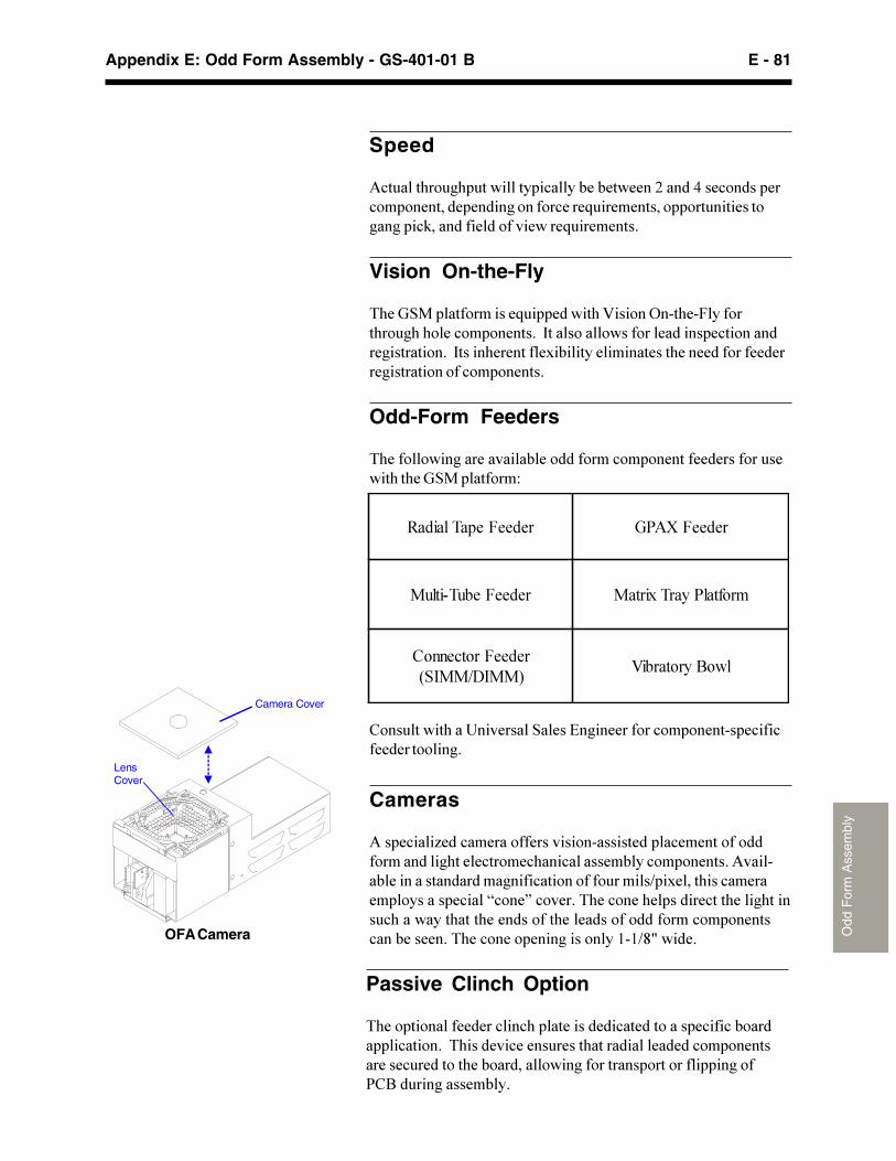
E - 81Appendix E: Odd Form Assembly - GS-401-01 B
Odd
For
m A
ssem
bly
Passive Clinch Option
���������������������������������������������������������������������������������������������������������������������������������������������������������������������������������/)�����������������
Speed
&������������������������������������9�����5������������������������������������������� �������������������������������$���������������������� ���������
Vision On-the-Fly
���� ��������������� �����������7������(�����.������������������������������'������������������������������������������������'������������������������������������������������������������������������
Odd-Form Feeders
������������������������������������������������������������������� ����������+
)������������!���������������*�������������������������������������������
Cameras
&���������-�������������������������������������������������������������������������������������������������&�����������������������������������������������B�����������������������������������C����D�����������������������������������������������������������������������������������������������������������������������������������4�4BA=������OFA Camera
LensCover
Camera Cover
�������������� �������� �
��������������� ������� ���������
������������������������ !
�"�#�������$

E - 82 GS-401-01 B- Appendix E: Odd Form AssemblyO
dd F
orm
Ass
embl
y
This page intentionally left blank.
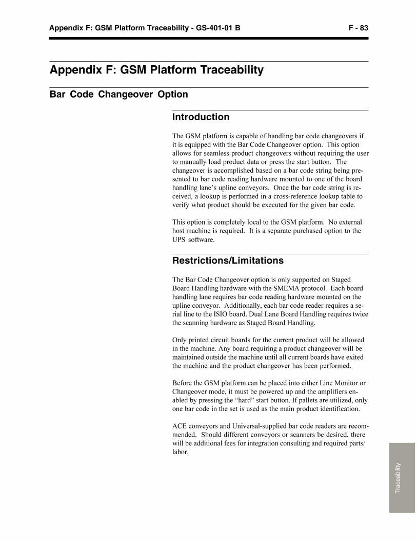
F - 83Appendix F: GSM Platform Traceability - GS-401-01 B
Tra
ceab
ility
Appendix F: GSM Platform Traceability
Bar Code Changeover Option
Introduction
����������� ����������� ������������� �������� ����������������������������������� �������� ���� ��� ��������� ��� � ���� ����������� ���������� ��������� ���������������������� ������ ���� �������� ��������������������� ������������ ��������� ������������� ������� ���������������������������� ����� ������������������ ������� � ��� ������� ����������� ��������� ���� �����!������������ ����������������������"�� #���������� ����������� ������������� #�������� ������������� ������� �������$�������� ���������������� ���
����� ��� ������ ������� ��� ������������ �����% ��$����� ������������������������&���������������������� ��� ��� ����'(�� � ������
Restrictions/Limitations
�������� �������� ���� ��� ����� ������� ����� �������� ���)������������������������*�+��� � � ���*���� ������������������������� ������������������ ������ ������������ ���� ����+����� ��"��������� ������������������������������ �����&�&!�� ����,��-���� ���)������������������������������������������������ ���)������
!�������������������� ����� ���������������� ����������� ������������������+���� ���������������� ���������� ������������������ ��������������������������������� ���������$������������������������ ���������� ���������������� �����
��� �������������� ����������������� ��������-����� ��� �� ������ ����� ��"������������� ������������������������������������������������.���/���������� ���&��������������0��"� �� ������� ���������������������������������� ���������������� ��
+�*�� ���� ������'������������������� ���������������� ������������� �������������� ���� ��� ��������������������"����������������� �������� ���������� ��� ������������������������1� ��
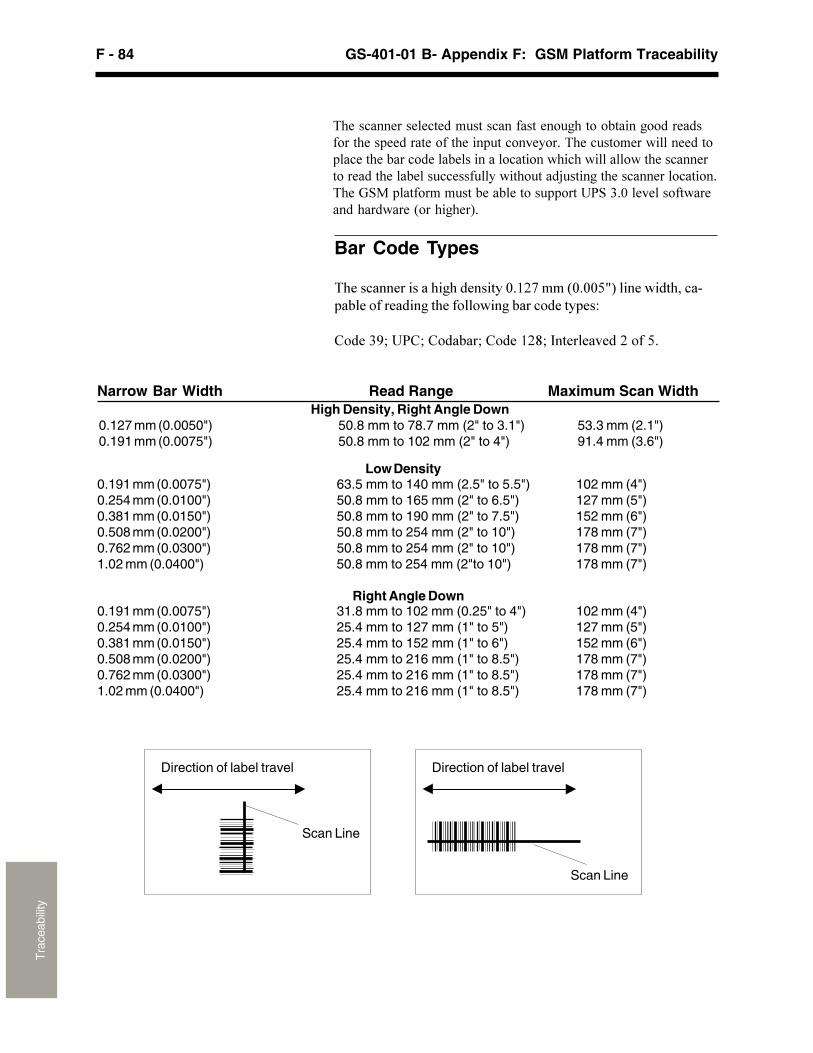
F - 84 GS-401-01 B- Appendix F: GSM Platform TraceabilityT
race
abili
ty
Bar Code Types
����������������������� �������������������������� ������������� ������� ��� ���������������� ����!
"����#$; %&"; "�����; "������'; (� ����)������ ���
���������������������������������� ����� � ������ ������� ���������������� ������������� ���� ����������� ������������� ������������ ����������� ��� ����������� ������������� ��������������������������� ����2������������������ ��� ������������� ��������������� ����� ���'(��3�4������ ���������������5 ��������6�
Narrow Bar Width Read Range Maximum Scan WidthHigh Density, Right Angle Down
0.127 mm (0.0050") 50.8 mm to 78.7 mm (2" to 3.1") 53.3 mm (2.1")0.191 mm (0.0075") 50.8 mm to 102 mm (2" to 4") 91.4 mm (3.6")
0.191 mm (0.0075") 63.5 mm to 140 mm (2.5" to 5.5") 102 mm (4")0.254 mm (0.0100") 50.8 mm to 165 mm (2" to 6.5") 127 mm (5")0.381 mm (0.0150") 50.8 mm to 190 mm (2" to 7.5") 152 mm (6")0.508 mm (0.0200") 50.8 mm to 254 mm (2" to 10") 178 mm (7")0.762 mm (0.0300") 50.8 mm to 254 mm (2" to 10") 178 mm (7")1.02 mm (0.0400") 50.8 mm to 254 mm (2"to 10") 178 mm (7")
Right Angle Down0.191 mm (0.0075") 31.8 mm to 102 mm (0.25" to 4") 102 mm (4")0.254 mm (0.0100") 25.4 mm to 127 mm (1" to 5") 127 mm (5")0.381 mm (0.0150") 25.4 mm to 152 mm (1" to 6") 152 mm (6")0.508 mm (0.0200") 25.4 mm to 216 mm (1" to 8.5") 178 mm (7")0.762 mm (0.0300") 25.4 mm to 216 mm (1" to 8.5") 178 mm (7")1.02 mm (0.0400") 25.4 mm to 216 mm (1" to 8.5") 178 mm (7")
Direction of label travel
Scan Line
Direction of label travel
Scan Line
Low Density
F - 85Appendix F: GSM Platform Traceability - GS-401-01 B
Tra
ceab
ility
Platform Setup Validation (PSV) Option
Introduction
����*+,���� ���������-��� ��&�� ���+� -��.���� ���&+.����������)�� ������ ����� ��������-��� ������ -���������������)� ���� ������� ��������� ������������ �� ������� � �������� ����&+.����/������-� ���� ��������-�������0�� ���������)������-� �������������)�����)���� ������������� ��0������� ���������-� �������������-� ��- ������,��������� �� ��������1-����-�� �� ������������������������ �����������������0�� � ����������-��� � � ����
(������ ���&+.���)�����-���-������ �!2 ��������� ������ ������ � �� ���� ������� ���� �������
����� ������0���� ������-��� ������� � ������������������� ������������� �� ��������� �� �������� ������)��� ���� ���������-� ������ ���*+,���� ���
2 ����������� ������ �������+����&+.�������)�������������� ������������� ���� �������� �� ����������������� ������������� ���0���� �-����)�� ������������� �����0�
2 �������� �������� ��3�����&+.����-������� ���������� �-��������������� ��-�������)����� ����� �����0����������-��� ���������� �������������4��������-� � ��������-� �����������������
2 ���������� � ���� ����� &+.�����������-��� ������� �������� ������������ � �������������� ��(������������-������� ����-��� ���*+,���� ��������� ������������� ��� ���� ����-������� +���� ��� ����� ����0���)���������������������� ����������������-����������-� ���
5� ��������%�)����6�������������������������������� ����)��� ����������������������-��� ������-� ���� ����1-�� ��������
F - 86 GS-401-01 B- Appendix F: GSM Platform TraceabilityT
race
abili
ty
PSV Specifications2 7�1-���%&+�#������� ���� ����2 +-��� ���5��"����8�����9��� �!
"���������#$��$#��������':�%&"�3�����;���� ��<�������:;3=>?3=:�+ ��������� ��:�(� ����)������ ��:�"������
2 +���&�9��� ������������3�@�� ���)�������&�9�������������0 �������������/���1-���� ��
PSV on PTF Assumptions andLimitations2 "������� ���������� �� ���&�9���� ����������� ��0��
�� <� ���������������;+A����0������ ���������������� <��� �� ������� �� ���� ��� ����������� ������� ��>��� ������� ��� �������������� ����� ����� ������������������� ����������� ������0�������� ������ �����)��� ���� ��0�� � ���� ��� ����������������� ��� ���&�9������ ��,�� ����� ��������� �����- ���� ���������� � ���&+.���� ��������1-�� ��� � ��)���� ������� ������ �� -�� ����������� ������������ ��� ���1-�� ��� � ���-��6�����- ��� ����� ����� ��������� ����� ����� ����������� ������ ���������������� �� ���� �� ����
2 3������ ����������������� ����� ��� ���� ���� ��0��� ��������� ����������������� ���������� �� ����������&+.� ���� �� ��� ) �� ���������)�-���� ��0��&+.�����1-�� �� ��� �� ���� ��� ��0��������������)��� �� �� ���&�9������ ������)��� ��� ������/����������� ���������� �������� ��0����� ���-�������� � ����������� ��0���� �������������������� ��� ���� � ������/����������� �� ��� � ��������������� ���� ��0�����&+.: &+.�����-��� ������ �������� ������������ �� �� �������� ��0��� �������� ���������������� �����-�� �� �������� �������������������������� ��������� ��0�� ��&�9������ �
2 ( �������������� �� ������ �����-��-� �� ���������� ��( ��� �� ������ ������ ������ �������������������� ������������ ��0������������ ��0�� � ����� ������� ���� �������������-���������������������������������������������������������� ���������� ��� <� ��� ���� ������ ������<��� ��� ����&+.�������� � ���������� �(A�������� ��������������� �>��� ��������� � �� ����������� ���� ����� ������������ �������� ��0� ����������� ��� ���&�9�
2 &+.����&�9��1-���5������&��1-��B ����+���&�9C� ������� ���� ������3�@��
F - 87Appendix F: GSM Platform Traceability - GS-401-01 B
Tra
ceab
ility
����*�����;1-���� �,������*;,���� �����)����-����� ������� ��� ���������� ����-������A�������D�,��- ��� -���,�� �������)�������� �� �����-��� ������ ��������� �������������������� ��� ����� ��*+,���� ������5������� ���+������-� ��;1-���� �����,� �����(� ��� ������ ��������+;,(�;#��$#�� ����� �����)�������� ������ ������� �� -�� ��� ��� ���� �� �� ����� �������� ��������- ��� ����� ����
Dimensions Manufacturing Monitoring
%�)�����(�� -��� �6�A��������,��- �� -���,�� ���+� �����A,,��������� ��� ���������� ����������� ��������� ������ ������������������� ��� �� ������-� ��� ����1-���� ��A,,������� ������)������������������)����� ���� )�� �� ���������� � �������-��������A,,������� ���������������� ������� ��(����������� ��-��� ������� ���������� �����3���������� ���� �� ����������)���������������������� ������� �������-���
A,,���������� ����-� �������>��-�1-�������� ����� �1-���� ��� ��- ���� �����������������- �/����-� ����� �-� ����/��������� �� -����-���� ��� ��� ��������������� ���� ������������� �-��������)����� �������� ������������������ ��� ������ ���� �� -���A,,��-��� ��-� �)������1-���� ����-���� ���+;"+>*;,�����-��� ���� ���������� ������ ������� ��������- �� -�����-� ��
����A,,���� �� -����������-�������-� � ������ ����������������� �-� ������- ����(���������� ���������� ������ ��-����������-����� � -�� ���� ����������� �������� ����1-���� ��� � �������-����"����� �������� ��������� �������� ���������� ��� �� -��������� ������ ���+&"������ �������)�������� � ����A,,��������- �/�������������� ���83=�� ��� ������-� �����)����� ��� �������� -������ ��� ���� ������<� ����� ��0��������
9������������1-���� �������� ��������������� ���� ������������� -�� ���� ���A,,�� ��� ��������� ��� ���������� ������������)��� ������ ���C���1-���� � �� �� ��� �� -�� ���� ����� ��������� ��� �� �-�1-������� ��� ������)�-���&"5�������������� �������������� ���� �������� ���� A,,� �����-���� �� ���������������������� �-���������� �-�����)������-�����������-�������� �> ���� �������� -�� ���� ��������� ��-����� �����)�� ������ ������0����������������-� ������� ��0�� �����������������1-�0������������
7� ������A,,�*������+��� �� ���*+�@�����3� ������� ����
GEM Host Interface Driver

F - 88 GS-401-01 B- Appendix F: GSM Platform TraceabilityT
race
abili
ty
This page intentionally left blank.