Embed Size (px)
Citation preview
INSTRUCTIONMANUAL
DC HIPOT TESTER(DC INSULATION)MODEL: DAHP-6010/8010
DAHP-6020/8020
ISO9001:2000
ELECTRIC.COProduct Features and Objects to Measure
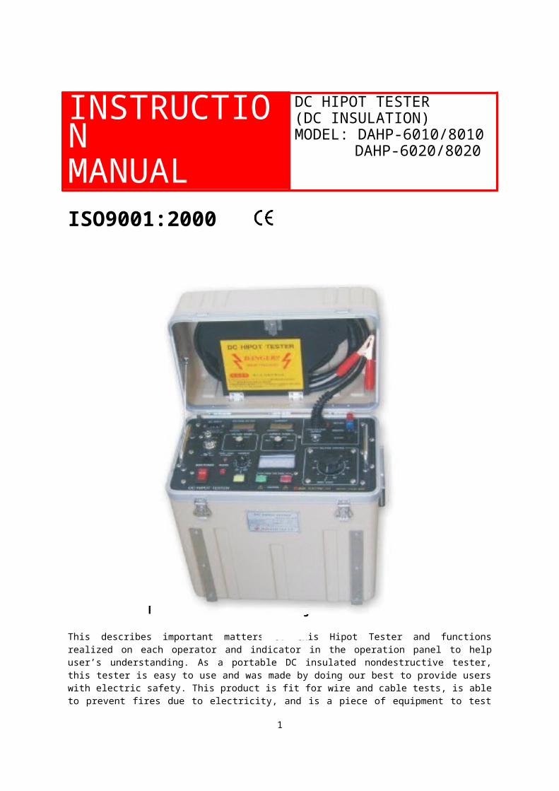
This describes important matters of this Hipot Tester and functions realized on each operator and indicator in the operation panel to help user’s understanding. As a portable DC insulated nondestructive tester, this tester is easy to use and was made by doing our best to provide users with electric safety. This product is fit for wire and cable tests, is able to prevent fires due to electricity, and is a piece of equipment to test insulated cables, condensers and things grounded on one side. Besides, this product was designed to protect users and equipment and was dedicated to preventing damage even though it was repeatedly tested at minimum and maximum output.
Features on Design and Safety● Portable and one piece● Provided with protection circuits● Provided with zero start interlock switches● 2range voltmeter and 4range ammeter
1

● No internal electric leaks during maximum load● Regular overload relay● Current limit resistance to limit overcurrent during HV output● Adoption of voltmeters, ammeters, LCD, and 3½ digit meters● Furnished with current setting V.R for current trip● Furnished with external interlock devices● Adoption of output current ratio(%) meters● Continuous outputting of output voltage● High pressure tank temperature rise alarm device● Provided with an overload switch to prevent overload● Alarm devices in case of no ground
Objects to Measure● Cable● Transformer● Motors● Generators● Electric switch● Other electric equipment, etc.
DC HIPOT TESTER
- Warning-
This tester is supposed to test or run at high voltage, so users shall use it after being fully aware of this instruction manual. Therefore, this product is internally provided with a safety device to the maximum and this instruction manual describes the best safety technology, so abide by the following rules thoroughly and be sure to use it after being fully aware of this instruction manual. Using this product without being fully aware of this instruction manual can result in fatal burns to human body or life accidents due to electric shocks.
▪ Users are advised to be fully aware of this instruction manual before starting actual test.▪ Grasp the place where you worked, and check if all electric circuits are OFF and separated.
▪ Never work alone. Always work along with other qualified experts.2
▪ Separate the space where work is performed to prevent other people from having access to it by using obstacles around it or by enclosing it with a warning tape.
▪ Inform all people of the test work.▪ Testers are advised to wear a pair of insulated rubber gloves while using this product.
▪ Be fully aware of the dangerous conditions subject to occurrence by operating the tested object.
▪ Never alter the test equipment. Altering the equipment can result in a new risk and malfunctioning of built-in safety devices.
▪ Arbitrary renovation, separation or repair can make you ineligible for receiving free repair.
▪ Never use the damaged equipment, and intercept the power and do not use the equipment until the service expert confirms that the equipment is safe to use.
▪ Do not give strong impacts or pierce it with a sharp thing.▪ When the product is wet or submerged in the water, bring it immediately to the A/S center of Dada Electric Co., Ltd.
▪ Keep it in the room between 0℃~+40℃ by avoiding the place with direct sunshine or the closed place with high temperature and humidity.
▪ Do not use the damaged power cord or plug or the loose outlet.▪ Do not touch the power plug with a wet hand or pull out the cord part.▪ Do not damage or severely bend the power cord.▪ Abide by the regulations, directions and signals in the region with explosion risk.
▪ Moisture or liquid ingredients give damage to the components and circuits of this equipment, so avoid humid places during custody and keep it in a dry place.
▪ Dust can be a cause of circuit trouble, so avoid the dusty or dirty places during custody.
▪ Dropping this product can result in its damage due to the impact to become a cause of trouble, so do not put it on the slope for custody.
▪ Locating this product together with magnetic objects can result in malfunction of the equipment due to magnetism, so do not locate it in a place affected by magnetism.
▪ Do not use this equipment for other purposes than the original one.▪ Be sure to use the A/S center of Dada Electric Co., Ltd. for repairs.▪ Dada Electric doesn’t take any responsibility for the results derived from failure
to keep the safety instructions or from improper use of the equipment.
3
List of Contents
1. Specification ……………………………………………………………………………… 4
2. Name and Explanation of each Part………………………………………………………… 5
3. Function and Explanation of each Part…………………………………………………………… 6
3.1 Voltmeter and voltage range……………………………………………………………………… 6
3.2 Ammeter and current range………………………………………………………………………… 6
3.3 Configuration and operation of main power…………………………………………………… 6
3.4 Configuration and operation of high voltage………………………………………………… 6
3.5 Configuration and operation of voltage regulator……………………………………………… 6
3.6 TEMP.OVER(temperature rise alarm for high pressure tank)………………………… 6
3.7 How to use the guard, ground and return terminal …………………………………………… 7
3.8 Jumper wiring between the ground and guard………………………………………………… 7
3.9 Jumper wiring between the ground and return………………………………………………… 8
3.10 How to use the EXT.INTLK connector…………………………………………………………… 9
3.11 How to use the current trip setting and reset…………………………………………………… 9
4
3.12 Analog current indicator………………………………………………………………………… 9
3.13 Thermal overload(temperature overload)……………………………………………………… 9
4. How to Install the Tester ……………………………………………………………………………… 10
5. Sequence of Operation Tests………………………………………………………………………… 10
6. High Voltage Cable Test………………………………………………………………………………… 11
7. Other Explanation on Safety…………………………………………………………………………… 12
7.1 Finishing procedure………………………………………………………………………………… 12
8.Testing the Large Capacitive Loads……………………………………………………………… 12
9. Guide to Troubleshooting……………………………………………………………………………… 13
10. Custody of Equipment………………………………………………………………………………… 14
11. Warranty………………………………………………………………………………………………… 15
TECHNICAL SPECIFICATIONSMODEL DAHP 6010 DAHP 6020
Input voltage 1ΦAC220
V 10A
frequenc
y50Hz/60Hz Input
voltage 1ΦAC220V 10A
Frequency
50Hz/60Hz
Output voltage(MA
X) DC
0~60KvOutput
current(MAX)
10㎃Output
voltage(MAX)
DC 0~60Kv
Output current(MA
X)20㎃
Weight About 29.2Kg
Instrument error
0.5% of full scale
Weight
About 29.5Kg
Instrument error
0.5% of full scale
Continuous rating
60KV 10㎃ 1hour ON/1 hour OFF60KV 10㎃ 1hour ON/1 hour OFF60KV 15㎃ 30 minute ON/1 hour OFF60KV 20㎃ 40seconds ON/1 hour OFF
Voltagepolarity Negative output, positive ground
5
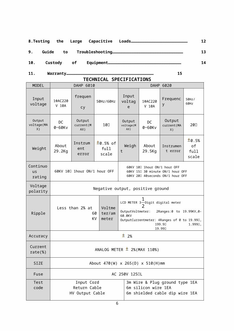
Ripple Less than 2% at 60KVVoltmeter/ammeter
LCD METER 312
Digit digital meter
OutputVoltmeter: 2Ranges:0 to 19.99KV,0-60.0KVOutputCurrentmeter: 4Ranges of 0 to 19.99㎂,
199.9㎂ 1.999㎃, 19.99㎃
Accuracy 2%
Current rate(%) ANALOG METER 2%(MAX 110%)
SIZE About 470(W) x 265(D) x 510(H)mm
Fuse AC 250V 125㎃L
Test codeInput Cord
Return CableHV Output Cable
Ground Cable
3m Wire & Plug ground type 1EA6m silicon wire 1EA6m shielded cable dip wire 1EA6m silicon wire 1EA
Operating Ambient Temperature 0 to 40 degrees Celsius
A statement of the degree of protection IPX0
MODEL DAHP 8010 DAHP 8020
Input voltage 1ΦAC220
V 10A
frequenc
y50Hz/60Hz Input
voltage 1ΦAC220V 10A
Frequency
50Hz/60Hz
Output voltage(MA
X) DC
0~80KvOutput
current(MAX)
10㎃Output
voltage(MAX)
DC 0~80Kv
Output current(MA
X)20㎃
Weight About 32Kg
Instrument error
0.5% of full scale
Weight
About 32.5Kg
Instrument
error
0.5% of full scale
Continuous rating
80KV 10㎃ 1hour ON/1 hour OFF80KV 10㎃ 1hour ON/1 hour OFF80KV 15㎃ 20 minute ON/1 hour OFF80KV 20㎃ 30seconds ON/1 hour OFF
Voltagepolarity Negative output, positive ground
Ripple Less than 2% at 80KVVoltmeter/ammeter
LCD METER 312
Digit digital meter
OutputVoltmeter: 2Ranges:0 to 19.99KV,0-60.0KVOutputCurrentmeter: 4Ranges of 0 to 19.99㎂,
199.9㎂ 1.999㎃, 19.99㎃
6
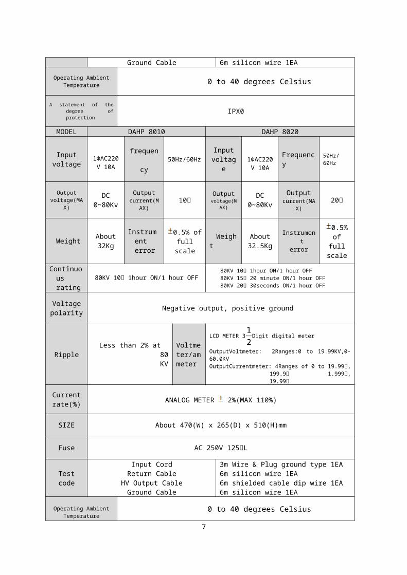
Current rate(%) ANALOG METER 2%(MAX 110%)
SIZE About 470(W) x 265(D) x 510(H)mm
Fuse AC 250V 125㎃L
Test codeInput Cord
Return CableHV Output Cable
Ground Cable
3m Wire & Plug ground type 1EA6m silicon wire 1EA6m shielded cable dip wire 1EA6m silicon wire 1EA
Operating Ambient Temperature 0 to 40 degrees Celsius
A statement of the degree of protection IPX0
Name and Explanation of each Part
AC INPUT: Power input connector(AC220V 50/60Hz) GROUND TERMINAL: Ground terminal of this equipment EXT.INTLK(INTERLOCK): External power interception S/W CURRENT TRIP: Current interception setting volume FUSE: Control power fuse TEMP.OVER/E-CHECK: High pressure tank temperature rise alarm and e-check LED MAIN POWER: Power ON/OFF S/W BUZZER: Buzzer ON/OFF S/W RESET: Reset S/W and display lamp during current interception HIGH VOLTAGE ON: Output power ON S/W lamp HIGH VOLTAGE OFF: Output power OFF S/W lamp
7
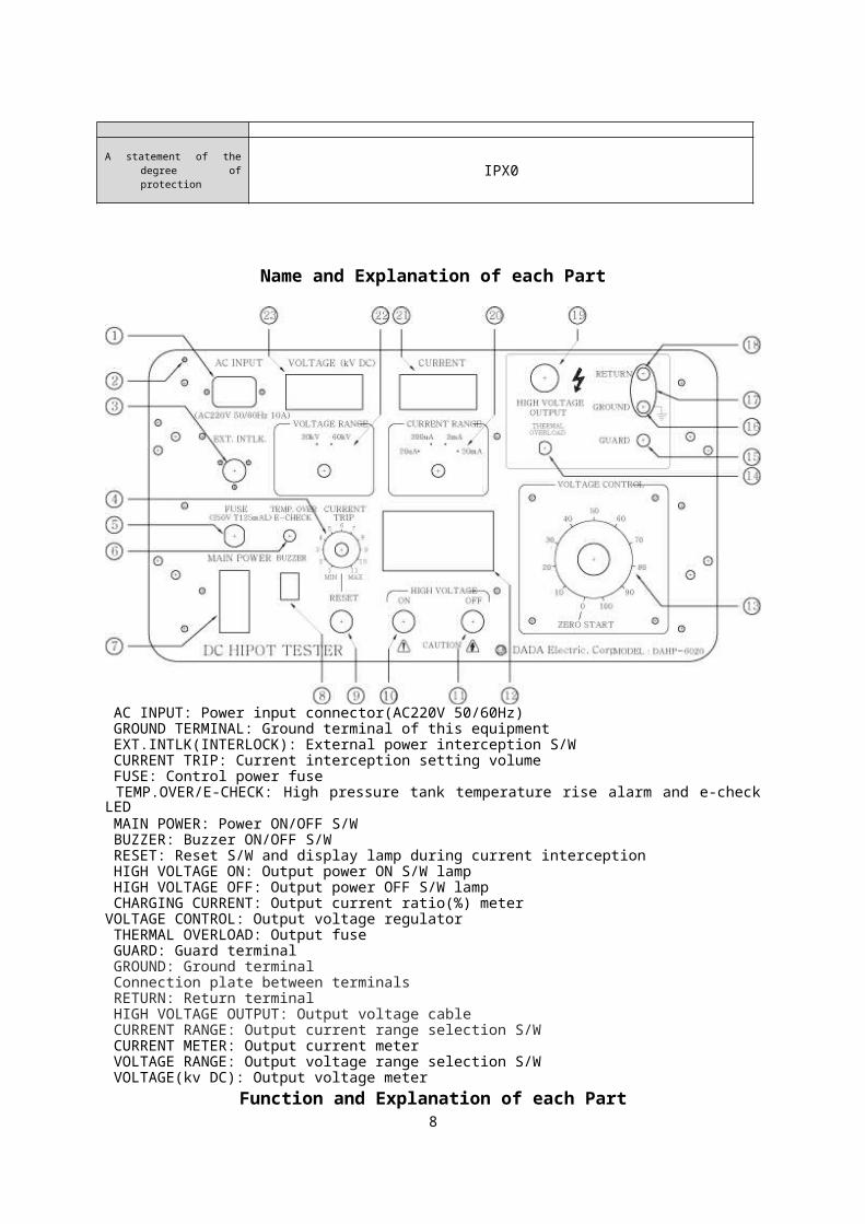
CHARGING CURRENT: Output current ratio(%) meterVOLTAGE CONTROL: Output voltage regulator THERMAL OVERLOAD: Output fuse GUARD: Guard terminal GROUND: Ground terminal Connection plate between terminals RETURN: Return terminal HIGH VOLTAGE OUTPUT: Output voltage cable CURRENT RANGE: Output current range selection S/W CURRENT METER: Output current meter VOLTAGE RANGE: Output voltage range selection S/W VOLTAGE(kv DC): Output voltage meter
Function and Explanation of each Part1. Voltmeter and Voltage Range(Voltmeter KV DC and Range Selector)
The DC KV voltmeter is located at the middle top of the operation panel and is printed with DC KV on the top of LCD meter. There is a 2range(20KV, 60KV) selector S/W of the KV meter just beneath it. Carry out measurement by selecting a proper range among 20KV and 60KV for accuracy of the LCD KV meter.Range 20KV: 0.00~19.99KV 60KV: 00.0~60.0KV 80KV: 00.0~80KV
Note: Output voltage meter display methodWhen measured voltage is 10KV
Range 20KV 60KV
KV METER -10.00KV -10.0KV
2. Ammeter and Current Range(Current and Selector)
The ammeter is located at the right center of the operation panel and is printed with CURRENT on the top of the LCD meter. There is a 4range(20㎂, 200㎂, 2㎃, 20㎃) selectors S/W of the ammeter just beneath it. Put and use the range selector at a proper range in order to obtain an accurate measurement value.Range: DAHP6010/DAHP8010: 10.00㎂, 100.0㎂, 1.000㎃, 10.00㎃
DAHP6020/DAHP8020: 19.99㎂, 199.9㎂, 1.999㎃, 19.99㎃
Note: Output current meter display methodWhen measured current is 10uA
Range
DAHP6010/8010
10uA 100uA 1㎃ 10㎃
DAHP6020/80
2020uA 200uA 2㎃ 20㎃
Ammeter 10.00uA 10.0uA .010㎃ 0.01㎃
3. Configuration and Operation of the Main Power Circuit Breaker
Pressing the power S/W in the operation panel lights up the S/W lamp and supplies power to the equipment.(Exceeding the rated current of the S/W operates the S/W breaker and intercepts power.)
8
Note: : Main separation OFF(power) : Main connection ON(power)
4. Configuration and Operation of the High Voltage
The high voltage in the operation panel is composed of the ON/OFF switches and the red H.L lamp. Pushing the high voltage S/W lights up the lamp, and raising the voltage regulator from zero start outputs the voltage.5. Configuration and Operation of the Voltage Regulator(Voltage Control)
The voltage regulator is located at the right side of the operation panel and is provided with a zero start interlock S/W. The voltage regulator is operated only by always starting at zero. If it is not at zero, the voltage makes no output no matter how much the regulator is turned. Besides, voltage never makes any output even though the high voltage S/W is turned ON during the use of the equipment. The voltage regulator must be turned ON at zero for voltage to make some output.
Note: ① Turning the voltage regulator to zero makes a snap sound. At this time, the voltage regulator is located at zero.
② The users must put the voltage regulator at zero by all means when not using it and must be very careful in slowly turning the voltage regulator and putting it at zero immediately as soon as the test is finished.
6. TEMP.OVER(High pressure tank temperature rise alarm)
Rising of high pressure tank temperature above 100℃ lights up the TEMP.OVER LED on the panel and makes the buzzer go off. At this time, using the equipment continuously can result in troubles to the equipment, so be careful. Going off of intermittent sounds from the e-check buzzer and flashing of LED indicates that there is no ground wiring with this equipment, so check the wiring and then use it.Reference: Sometimes an alarm sound may go off when the ground current is zero. At
this time, continuous use is possible. Using generator power or a transformer can make the alarm LED light up and the buzzer go off because ground current doesn’t flow even though there is ground connection, so refer to it when using the equipment.
In order to intercept the alarm sound in case of no ground, putting the buzzer S/W to OFF makes the e-check LED flash continuously and the sound not go off at this time, so continuous measurement is possible. However, it is possible only when grounding is installed for sure.
7. How to Use the Guard, Ground and Return Terminal
There are 3 test terminals such as guard, ground and return ones in the operation panel. The guard or return terminal should be always connected to the ground terminal via a jumper before starting the test.
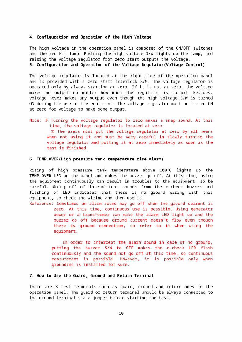
8. Jumper Wiring between Ground and Guard(See the circuit diagram in Fig.3)
The test method of ground and guard is for separating 2 kinds of leaked currents. These 2 kinds of leaked currents are the current we are going to check and the leaked current we may not check. Testing it by wiring the ground and guard terminals via a jumper can measure the leaked current we are going to check exactly via a ammeter and make the other leaked current bypass the ammeter. That is, it flows directly to the ground.
9
<Figure 3. Circuit diagram>
Only the leaked current flowing on or in the actually tested object is measured, but the leaked current flowing to the ground is neglected. The most exact leaked current is measured by this test method.
Note: ① The cable shield is always grounded, so this test cannot test the installed cable. That is, it is impossible to measure the leaked current.
② Tests are possible only when the tested object is not grounded, so tests are possible only when the leaked current flowing to the separately branched components or the ground is neglected. For example, when testing the leaked current in a transformer between primary and secondary sides, the guard return test method makes the leaked current flowing to the core or frame bypass to the ammeter. Like this, only the leaked current between 2 coils is measured.
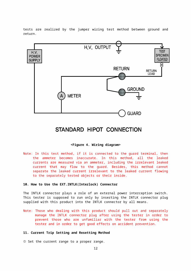
9. Jumper Wiring between Ground and Return(See the circuit diagram in Fig.4)
The jumper wiring test between ground and return is used when the total leaked current is checked and when exact measurement is necessary. This is a commonly used method and the most generally used method. Almost all cable tests are realized by the jumper wiring test method between ground and return.
10
<Figure 4. Wiring diagram>
Note: In this test method, if it is connected to the guard terminal, then the ammeter becomes inaccurate. In this method, all the leaked currents are measured via an ammeter, including the irrelevant leaked current that may flow to the guard. Besides, this method cannot separate the leaked current irrelevant to the leaked current flowing to the separately tested objects or their inside.
10. How to Use the EXT.INTLK(Interlock) Connector
The INTLK connector plays a role of an external power interception switch. This tester is supposed to run only by inserting the INTLK connector plug supplied with this product into the INTLK connector by all means.
Note: Those who dealing with this product should pull out and separately manage the INTLK connector plug after using the tester in order to prevent those who are unfamiliar with the tester from using the tester and in order to get good effects on accident prevention.
11. Current Trip Setting and Resetting Method
① Set the current range to a proper range.② The number of current trip VR multiplied by 10 becomes a set current for the
percentage of the set range value.③ It trips automatically when the output current exceeds the set trip current, and all
lamps of the high voltage ON/OFF S/W are turned off.④ During current trip, it is reset by pushing the reset S/W with the voltage regulator at
zero.12. Analog Current Indicator
The meter indicates 0~100% of the measurement range current in order to visually 11
display the capacity conditions and in order to show the current change conditions that are not easily judged by a digital meter.
13. Thermal Overload
The breaker mainly protects the high voltage transformer.If the breaker trips, press the high voltage OFF S/W and then turn the voltage control knob to zero before resetting it. If the breaker trips, cool the equipment enough in order to protect the equipment and then reuse it.
Tester Installation Method and Operation Test SequenceThe process by steps for test installation of this product is described below.
① Put it on a flat place by maintaining horizontality so that the scales on the meter may be exactly viewed.
② Adjust the voltage regulator to the zero and start position and then check if the main power switch is OFF.
③ Ground the terminal in the operation panel before inputting power to the power cord. Jumper wiring is needed between the ground and return terminals in order to perform
12
a cable test.④ Wire the return lead provided along with the equipment according to the figure. (Fig.4)
Note: Carelessly touching the test leads attached to this equipment without any safety measure can result in injury or fatal results due to electric shocks. Do not touch the test leads while tests are in progress. This equipment shall be operated only by the personnel who are familiar to the procedures and safety rules for high voltage tests. It is important to operate the equipment by wearing a pair of insulated rubber gloves when using the equipment as far as possible.
Operation Test SequenceThis part is for testing the insulation that is grounded at one side only and the insulation that is not grounded.
① Check if the tester is installed according to the instruction manual.② Check if the ammeter range is set in a proper range. It is desirable to set the first
current range to10㎃(20㎃). Set the current interception setting volume to the desired maximum current level pointer.
③ Check if the voltmeter range is set to the test voltage range.(20KV, 60/80KV)④ Connect the output cable cord to the tested object.⑤ Insert the INTLK plug.⑥ Insert the AC power cord to the 220V power. Note: If the 220V power outlet is not grounded, then ground it to the ground terminal
on the panel of this equipment by all means. Take care because the alarm LED may flash and the buzzer may go off as the ground current doesn’t flow even though it is grounded when using generator power or a transformer. It is possible to use the equipment even though an alarm takes place when generator power is used and grounded.
⑦ Turn on the main power switch.⑧ Turn on the high voltage switch.⑨ Turn the voltage control slowly and adjust it to the test voltage while seeing the output
voltmeter. Caution: If the voltmeter indicates a value higher than “0” even though tests have
been finished, then it has not been completely discharged, so do not touch the equipment with hands until it is completely discharged.
Note: If the tested object becomes wrong, the overload circuit stops the high voltage output, and when the high voltage in the inside with discharge resistance is short-circuited, the solenoid works to remove the charged high voltage in the tested object. However, at this time, it is possible only when the high voltage terminal connected to the object is not removed.
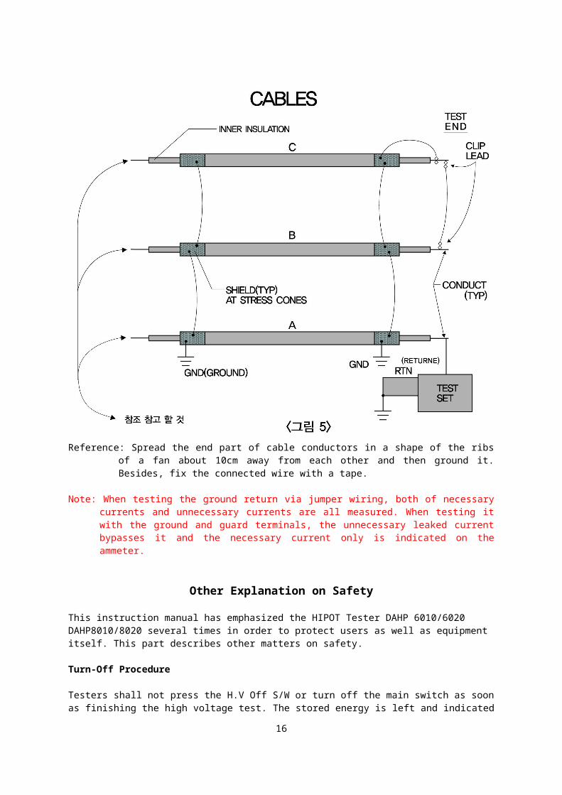
Testing of High Voltage Cables(See the wiring diagram in Fig.5)Carefully comply with many execution rules in operation sequence or handling methods of the equipment when carrying out wiring tests for three or single phase cables.
① All insulated cables shall be clean on its bare copper part and be free of dust or moisture.
② Check if the shield of three phase cables is grounded and the end part of the cable is bound.
③ When measuring each of three phase cables separately, ground the remaining 2 cables by all means in order to prevent dangerous charge from accumulating on the cable.
④ Increase voltage slowly by all means. Follow the test measurement values summarized by cable makers or IEC and K.S standard.
⑤ The results of the ammeter during tests of three phase cables shall be almost the same for 3 cables. Flashover means that it is higher than the expected value, cable
13
quality is bad, there is moisture, dust, etc. in the bare copper part, and there is leakage in the end part of the cable.
⑥ After completion of tests, proceed with a proper turnoff procedure.
Reference: Spread the end part of cable conductors in a shape of the ribs of a fan about 10cm away from each other and then ground it. Besides, fix the connected wire with a tape.
Note: When testing the ground return via jumper wiring, both of necessary currents and unnecessary currents are all measured. When testing it with the ground and guard terminals, the unnecessary leaked current bypasses it and the necessary current only is indicated on the ammeter.
Other Explanation on SafetyThis instruction manual has emphasized the HIPOT Tester DAHP 6010/6020 DAHP8010/8020 several times in order to protect users as well as equipment itself. This part describes other matters on safety.
Turn-Off Procedure
Testers shall not press the H.V Off S/W or turn off the main switch as soon as finishing the high voltage test. The stored energy is left and indicated on the voltmeter, so the stored energy shall be flown until the results on the voltmeter indicate zero.
14
Turn the voltage regulator slowly to the zero point.② Check if the ammeter range was set to 20㎃(DAHP-6010/8010:10㎃)③ Have the changed cable discharge so that the results of the voltmeter may reach
10KV.④ Have the cable discharge completely via a grounded insulation bar.
Testing Large Capacitive Loads
Proceed with the following procedures in order to protect users and equipment immediately after carrying out large capacitive insulation tests.
① Prepare a grounded insulation bar.② Discharge the charge in the cable or other places using an insulation bar. Doing like
this can omit discharge of capacitive cables entering the high voltage part when pressing the high voltage off button.
TroubleshootingDada Electric tests and ships all products according our stern criteria. If you send consumer’s complaints(causes of malfunction) and warranty when a problem happens to the product, we will exchange it and deal with the complaints immediately. Never disassemble the equipment or have a non-expert repair it within the warranty period. Refer to the table below to repair the troubles occurring most frequently.
Problem Countermeasure
The equipment won’t work.Check the input power of this equipment.Check the fuse.Check the display lamp.
The HIGH VOLTAGE ON switch is not turned on.
Check if the voltage control dial is at the zero start position.Check if the external interlock switch is connected.Check if the current trip value is too low.
15
Check the reset switch.
The voltage is not outputted. Check the trip or thermal overload.
The ammeter won’t work.Check if the tested object is wrong connected.Check the wiring of GURAD/GROUND/RETURN jumpers.
The voltmeter won’t work. Check if the meter has been damaged.There is no high voltage output.
There is no high voltage output.There is a defect in the measurement circuit.The shield of the high voltage cable has shorted.
Equipment Custody
Avoid the following places in order to keep the equipment in custody for a long time.
● Moist places
● Places with many vibrations and shocks
● Places full of severe dirt, dust or gas
● Places near high heat
● Keep the equipment in a room by all means.(Temperature: 0~50℃, Maximum humidity:95%)
● Other places having a bad effect on the equipment
16
<Warranty>
▫ ▫ ▫ Warranty Regulations ▫ ▫ ▫
In case of troubles in normal use during warranty period, we provide free repair or exchange for a new product.However, the following cases are excluded.
1. Troubles due to not using it according to the instruction manual2. Troubles due to improper repair or renovation other than our company’s service3. Component damage or consumption4. Damage due to falls during transportation after sale5. Damage to appearance6. Troubles due to fires, floods or abnormal voltage application
※ In case of other troubles, contact our company directly. We will do our best.▫ ▫ ▫ Warranty ▫ ▫ ▫
Product name Model
nameDC HIPOT TESTER
□ DAHP-6010/8010□ DAHP-6020/8020
Manufacture number
Warranty period
Purchase date Year Month for 1 year
In case of troubles or abnormality during use, our company will repair or exchange it with responsibility according to the warranty regulations. However, the warranty should be submitted.
17
Address: Zip code: Tel:
Name (Company Name)
※ Arrival of warranty at our company guarantees validity.The warranty is not reissued.
TEL: 82-32-675-4480~1 FAX: 82-32-675-4482
ELECTRIC.CO
18
ELECTRIC.CODADA ELECTRIC CORP, 175-3 Nae-dong, ojeong-gu, Bucheon-city, Gyeonggi-
do,Korea.Tel: (032) 675 – 4480~1Fax: (032) 675 – 4482
E-mail: [email protected] SITE: www.dadafl.co.kr
![H - NetfloFF]A1Netwokr_KOR.pdf2010/06/09 · H.264 고해상도Network Camera SNB-2000 제품특징 ·MultipleEncoding(H.264,MPEG-4,MJPEG) ·최대4CIF급(704x480)30fps전송가능](https://img.pdfslide.tips/doc/110x75/6100315c35730f68bd257e24/h-ffa1netwokrkorpdf-20100609-h264-efenetwork-camera-snb-2000.jpg)