Embed Size (px)
Citation preview

BRANDMASTER
Gas Fire Fighting ModuleImpulse-20 (25-22,5-18) Specifications 29.2-30784208-006:2011
Art. 01.1.01.0000
Impulse-2 (25-2,2-18) Specifications 29.2-30784208-006:2011Art. 02.1.01.0000
MANUAL(passport)
2013
Edition 003

This Manual devoted to Gas Fire Fighting Modules IMPULSE-20 (25-22,5-18) and IMPULSE-2 (25-2,2-18) (hereinafter referred to as “Module”) describes the structure and principles of operation, specifications, service lifetime and manufacturer’s warranty, instructions for application and use.
Modules’ specifications meet the requirements as follows:- National Standards 4095-2002 “Firefighting equipment. Gas fire suppression systems.
Modules and battery equipment. General technical requirements. Test methods”;- Labour Protection Regulatory Act 0.00-1.07-4 “Rules for design and safe operation of
pressure vessels”;- Labour Protection Regulatory Act 40.1-1.32-01 “Electrical Installation Regulations.
Electrical equipment of special installations”.
Gas fire-extinguishing agent used for the above modules meet the requirements as follows:- National Standards 3958-2000 “Gas fire-extinguishing agents. List of quality parameters,
general technical requirements ant test methods”;- National Standards 4466-5:2008 “Gas firefighting systems. Development, installation,
testing, maintenance and safety. Part 5. Fire-extinguishing agent FK-5-1-12”;- National Standards 4466-8:2008 “Gas firefighting systems. Development, installation,
testing, maintenance and safety. Part 8. Fire-extinguishing agent HCFC 125”;- National Standards 4466-9:2005 “Gas firefighting systems. Development, installation,
testing, maintenance and safety. Part 9. Fire-extinguishing agent HFC 227ea”;
It is recommended to follow the Manual Fire Safety Regulatory Act Б.01.004-2000 “Rules for maintenance of automatic firefighting installations”, while using the above modules.
1. GENERAL INFORMATION
1.1. Product identification to be used when ordering:
GFFM IMPULSE-20 (25-22,5-18) X Specifications 29.2-30784208-006:2011 1 2 3 4
where:
1 – Module operating pressure, bar;2 – Module capacity, L;3 – Nominal width diameter of the lock & release device;4 – Type of mounting;
W – wall-typeC – ceiling-type
Edition 003

GFFM IMPULSE-2 (25-2,5-18) X Specifications 29.2-30784208-006:2011 1 2 3 4
where:
1 – Module operating pressure, bar;2 – Module capacity, L;3 – Nominal width diameter of the lock & release device;4 – Type of mounting;
W – wall-typeC – ceiling-type
Example of marking description of the module GFFM IMPULSE-20 (25-22,5-18) –C:
where:
25 – Module operating pressure, bar;22,5 – Module capacity, L;18 – Nominal width diameter of the lock & release device, mm;C – ceiling-type of mounting
Example of marking description of the module GFFM IMPULSE-2 (25-2,5-18) –W:
where:
25 – Module operating pressure, bar;2,5 – Module capacity, L;18 – Nominal width diameter of the lock & release device, mm;W – ceiling-type of mounting
Purpose of the product: the above modules are designed for distinguishing of classes A, B, and C fires and electrical equipment (voltage not over 1000 V) by means of gas fire-extinguishing agents (GFA).
The modules are the sphere-shaped metal vessels containing the fire-extinguishing agent. The metal mounting is in the upper part of the vessel; the pulverizer with an electromechanical activator, manometer and pressure relay, safety diaphragm and thermally sensitive glass bottle is located in the module’s neck.
The modules may be used both as a part of automatic firefighting systems and independent firefighting device.
Pressure relay is designed for signaling when the module is activated (pressure is lower than 0.2 MPa).
The modules are forbidden to be used in explosion hazard zones.
Edition 003
The modules are produced in the “Moderate” climatic category with the placement category No. 3 as set forth in the National State Standard (GOST) 15150 and designed for exploitation at the ambient air temperature from minus 10°C up to plus 50°C and relative humidity maximum 80% at the air temperature +15°C.Specifications 29.2-30784208-006:2011.
2. SPECIFICATIONS
2.1. Modes of activation:
2.1.1. – Automatic – destruction of the bottle of the lock & release device’s thermal lock by means of the electromechanical activator (one-shot device), when the electric impulse is transferred from the fire controller;
2.1.2. Remote - destruction of the bottle of the lock & release device’s thermal lock by means of the electromechanical activator, when the electric impulse is transferred from the starter, pushing the remote control button;
2.1.3. Autonomous – destruction of the thermally sensitive bottle of the lock & release device by rising he temperature over 68°C.
Other specifications may be found in Table No. 1.Name, formula and peak load of the modules with the gas fire-extinguishing agents are described in Table No. 2.
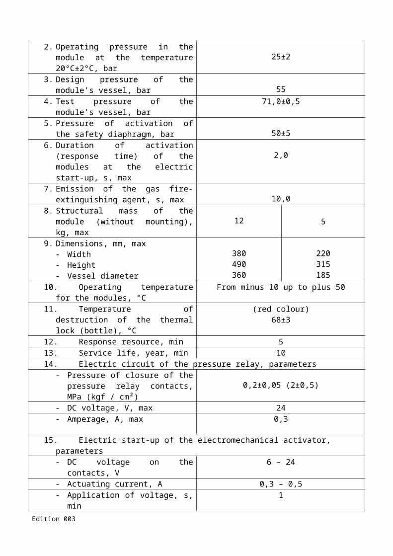
Table No. 1 Specifications of the module
Criteria Type of the module
IMPULSE-20(25-22,5-18)
IMPULSE-2(25-2,2-18)
1. Module capacity, L 22,5±0,5 2,2±0,22. Operating pressure in the module at the
temperature 20°C±2°C, bar 25±23. Design pressure of the module’s vessel,
bar 554. Test pressure of the module’s vessel, bar 71,0±0,55. Pressure of activation of the safety
diaphragm, bar 50±56. Duration of activation (response time) of
the modules at the electric start-up, s, max 2,07. Emission of the gas fire-extinguishing
agent, s, max 10,08. Structural mass of the module (without
mounting), kg, max 12 59. Dimensions, mm, max
- Width- Height- Vessel diameter
380490360
220315185
10. Operating temperature for the modules, °C From minus 10 up to plus 5011. Temperature of destruction of the thermal
lock (bottle), °C(red colour)
68±312. Response resource, min 5
Edition 003

13. Service life, year, min 1014. Electric circuit of the pressure relay, parameters
- Pressure of closure of the pressure relay contacts, MPa (kgf / cm²) 0,2±0,05 (2±0,5)
- DC voltage, V, max 24- Amperage, A, max 0,3
15. Electric start-up of the electromechanical activator, parameters- DC voltage on the contacts, V 6 – 24- Actuating current, A 0,3 – 0,5- Application of voltage, s, min 1- Resistance, Ohm 9 - 14- Amperage at the connectivity test (no-
damage current), A, max 0,01
Attention! Electromechanical activator is a one-shot device and subject to replacement when activated.
Table No. 2 Description of the gas fire-extinguishing agents (GFA) used in the modules
Name
Name of GFA, formula,peak load of the module, kg
HCFC 125*(Freon 125)СF3CHF2
HFC227ea*(Freon 227ea)
CF3CHFCF2
FK-1-5-12*CF3CF2C(O)CF(CF3)
2
Impulse-20 19 21 21Impulse-2 1,9 2,1 2,1
Notes*: Name of GFA as set forth by the National Standards of Ukraine 4466-8, 4466-9, 4466-5.
3. COMPLETE SET
The complete set includes:- Ready-assembled module with GFA;- Electromechanical activator;- Supporting frame (for wall-type and ceiling type mounting) with fixing bolt;- Technical passport and Manual;- Packing.
Edition 003
4. COMPOSITION, ORGANIZATION AND PRINCIPLES OF OPERATION
4.1. General appearance of the modules is given on drawing No. 1 and 2.
Gas fire-fighting modules “IMPULSE-20” and “IMPULSE-2” are characterized by the volume of the fire-extinguishing agent bottle and dimensions of the wall-type mounting.
Above modules includes 1 bottle, containing a liquefied GFA, which is mounted to the fittings 3 by the bolt 2. The pulverizer 4 with the electromechanical activator 6, manometer and pressure relay (РД-И60) 8, safety diaphragm 9 and thermally sensitive glass bottle 7 is located in the module’s neck. The electromechanical activator 6 is connected to the fire controller.
To connect to ground, a connection terminal 10 is used (drawing No. 3). To prevent an unauthorized start-up when the modules are transported, stored, installed and serviced, a blocking screw is installed in the pulverizer (diagram No. 3). The blocking screw is removed when the module is in standby.
a) b)
Diagram No. 1 General appearance of the “IMPULSE-20” modulea – wall-type mounting; b– ceiling-type mounting
a) b)
Diagram No. 2 General appearance of the “IMPULSE-2” modulea – wall-type mounting; b– ceiling-type mounting
Edition 003

Diagram No. 3 General appearance of the pulverizer
Manometer is designed for visual control over the module pressure. Contact lines of the pressure relay are connected to the control unit. When pressure in the module’s vessel is 0,2 MPa, the relay contacts are closing and the firefighting system is signaling about the start-up (pressure is lower than 0,2 MPa).
a) b)Diagram No. 4 General appearance and connecting dimensions of the “IMPULSE-20” module’s fittings
а) ceiling-type, б) wall-type
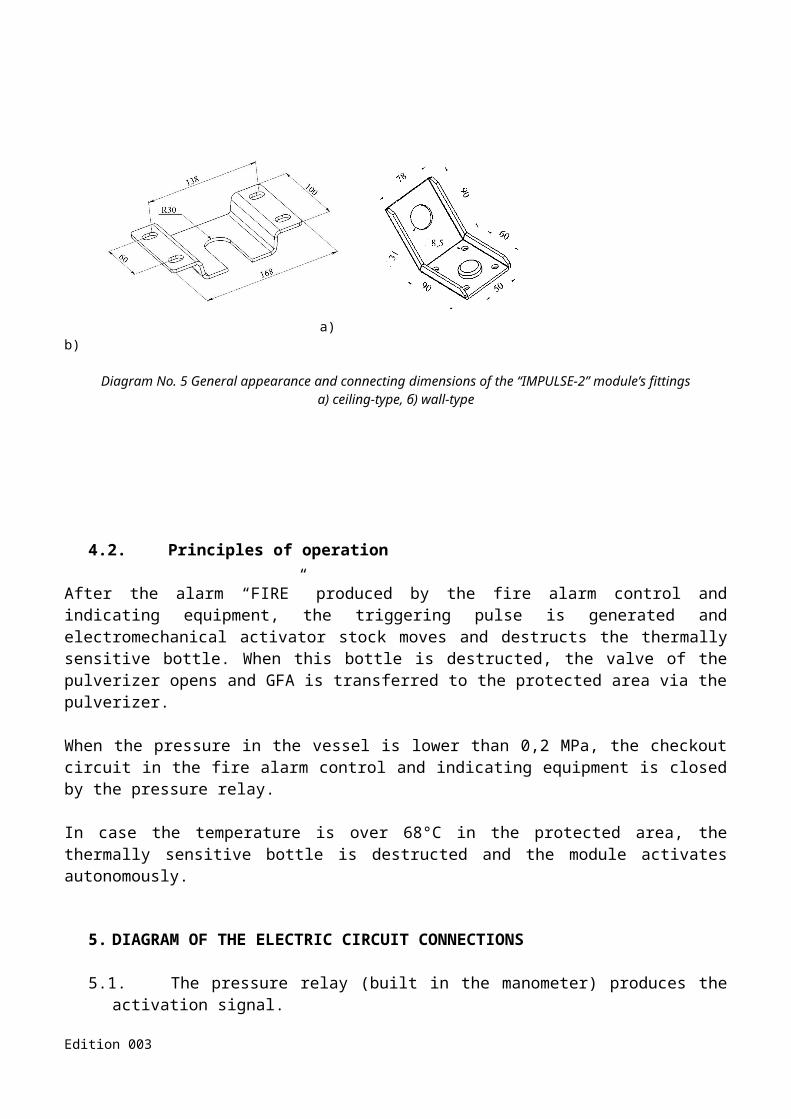
a) b)
Diagram No. 5 General appearance and connecting dimensions of the “IMPULSE-2” module’s fittings а) ceiling-type, б) wall-type
Edition 003

4.2. Principles of operation
After the alarm “FIRE” produced by the fire alarm control and indicating equipment, the triggering pulse is generated and electromechanical activator stock moves and destructs the thermally sensitive bottle. When this bottle is destructed, the valve of the pulverizer opens and GFA is transferred to the protected area via the pulverizer.
When the pressure in the vessel is lower than 0,2 MPa, the checkout circuit in the fire alarm control and indicating equipment is closed by the pressure relay.
In case the temperature is over 68°C in the protected area, the thermally sensitive bottle is destructed and the module activates autonomously.
5. DIAGRAM OF THE ELECTRIC CIRCUIT CONNECTIONS
5.1. The pressure relay (built in the manometer) produces the activation signal.
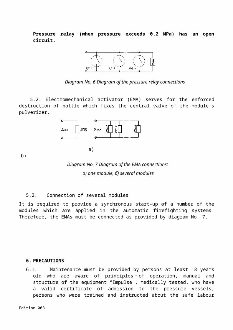
Pressure relay (when pressure exceeds 0,2 MPa) has an open circuit.
Diagram No. 6 Diagram of the pressure relay connections
5.2. Electromechanical activator (EMA) serves for the enforced destruction of bottle which fixes the central valve of the module’s pulverizer.
a) b)
Diagram No. 7 Diagram of the EMA connections:
а) one module, б) several modules
5.2. Connection of several modules
It is required to provide a synchronous start-up of a number of the modules which are applied in the automatic firefighting systems. Therefore, the EMAs must be connected as provided by diagram No. 7.
Edition 003

6. PRECAUTIONS
6.1. Maintenance must be provided by persons at least 18 years old who are aware of principles of operation, manual and structure of the equipment “Impulse”, medically tested, who have a valid certificate of admission to the pressure vessels; persons who were trained and instructed about the safe labour methods, passed the safety knowledge assessment in accordance with their position and work.
6.2. Working with the batteries, it is required to follow the safety rules described in this Manual and Labour Protection Regulatory Act 0.00-1.07-97 “Rules for design and safe operation of pressure vessels”.
6.3. Module disassembly, in case of extreme pressure, is forbidden.
6.4. Mounting and disassembly of the modules may be performed when the starting circuits are off only.
6.5. All mounting and disassembly work are subject to be performed by two persons at least.
6.6. Modules are forbidden to be set up in premises with probable direct sunlight and ambient temperature lower than minus 20°C and over plus 50°C.
6.7. Modules are forbidden to be installed closer than 1 meter to heating radiators and other heating appliances and 10 meters to furnaces and other heating appliances with open flame.
6.8. Modules cannot be used if a regular evaluation of cylinder damages has expired and hazardous damages have emerged.
6.9. Modules must be grounded or connected with the neutral conductor as provided by the Electrical Installation Regulations.
6.10. All work with the gas fire-extinguishing agents must be performed according to the safety and environmental regulations provided in the relevant regulatory acts.
6.11. Designing, servicing or using the firefighting system (module), it is recommended to remember that the gas fire-extinguishing agents emitted by the pulverizer may have a dangerous physical influence on human body.
6.12. Major hazards at the maintenance and exploitation of the modules:
6.12.1. - Traumatizing of employees due to the seal failure or destruction of pressure vessels and appliances (dispersion of solid fragments, high rate of gas discharge etc.);
- Poisoning of employees due to the gas fire-extinguishing agents and their vapor toxicity;
- Injury by current (if electric appliance’s live parts are broken, earth ground is out of order or individual protection is not applied);
- Lower temperature of the outside part of the module’s components or working air when the gas fire-extinguishing agent is emitted;
- Influence of the GFA on a human body when breathing in, contacting the skin, mouth mucous membranes, eyes, and gastro-intestinal tract.
Symptoms of the GFA influence on a human body:
- Short-time excitements changing with apathy, drowsiness, lower respiratory rhythm, and heart acceleration which occur when the GFA are breathed in.
- Eye watering, scratchy throat, cough, sharp pain in the nose and throat, asthma, seizures, lung damage. All these occur when the products of Freon thermal decomposition are breathed in;
Edition 003
- Frostbite body parts. This happens when a liquefied gas contacts open parts of a human body;
- Eye redness and watering. These occur in case of the eye contact.
6.12.2. If the GFA leakage occurs (due to the seal failure, destruction of the lock & release device’s membrane, or an accidental actuation), it is allowed to enter the premises in the personal protective equipment only;
6.12.3. If the GFA leaks, it is required:
- To removal staff from the hazardous area;
- To switch on the emergency or other ventilation devices;
- To determine the level of dangerous substances in the working area. To determine and register the level of the GFA concentration, use a stationary automatic gas analyzer or portable ones;
- To liquidate the emergency when the GFA concentration has reduced;
- To notify the administration (direct Head) about the emergency.
6.12.4. First aid treatment:
- In case of inhalation poisoning with the GFA:
Remove a victim to a fresh air. Free them from hindering clothing. Provide a victim with warmth, let them rest. If and other symptoms rise, ask for medical assistance. If a victim stops breathing, make the "mouth-to-mouth" artificial respiration.
- In case of skin contact:
Frostbite may be caused by liquefied gases which contact with open parts of an employee’s body.
In case of frostbite, pour the damaged skin and mucosa with warm water (maximum 40°C) until defrosting; make a bath with 40°C water and apply a dry aseptic dressing. Ask for medical assistance.
- In case of eye contact:
Wash eyes with warm current water (eye fissure must be wide) thoroughly. In case of a sharp pain, instill 1-2 drops of Novocain solution or 1 drop of 0,5% Dicaine solution. Then, instill 0,1% sulfuric zinc solution. Ask for medical assistance immediately.
6.13. Employees dealing with the modules must use the individual protective equipment (РУ-60М gas, vapor and aerosol respirators, gaslight goggles, protective gloves, special clothing protecting from gaseous and liquid toxic substances, and protective footwear).
6.14. Other safety requirements as provided by Chapter 5 of the National Standards of Ukraine 446-1:2008.
Attention! If any pressure in the module, install the blocking screw before maintenance or disassembly (Position No. 11, Diagram No. 3)
7. ACCEPTANCE AND SETTING-UP PROCEDURE
7.1. Keep the module at the constant temperature at least 8 hours.
7.2. Unpack the module:
7.2.1. Check the module’s completeness;Edition 003
7.2.2. Check the full weight of the module according to the technical passport;
7.2.3. Check the pressure in the module (check for compliance with diagrams in Appendix No. 1);
7.2.4. Check the packing list and order for compliance. In case of non-compliance, notify the manufacturer within 14 days after the receipt.
Attention! Immediately contact the manufacturer if any non-compliance of specifications, passport data, completeness, or appearance is discovered. Claims for completeness, mechanical damages, appearance or other non-compliances shall not be accepted upon 14 days from the date of shipment of the module to the client.
7.3. Installation of the module and requirements to installation
Attention! Installing the module, do not take the pulverizer and manometer in hand in order to save the module’s hermeticity. The module may be installed if the blocking screw is available only (Position No. 11, Diagram No. 3)
7.3.1. The modules are installed according to the project of the firefighting system and fixed to the wall or ceiling with fittings (Diagram No. 4 and No. 5). Fittings and support must carry a static loading at least 600 N and impulse dimanic loading at least 1000 N/s.
7.3.2. Electric circuits (of activator and pressure relay) must be mounted in a strict accordance to the project.
7.3.3. The module must be grounded by means of the connection terminal 10 (Diagram No. 3).
7.3.4. When the module is installed and electrical circuits are laid, the module should be connected to the control unit.
Attention! Remove the blocking screw when the module is installed and put the module in standy (Position No. 1, Diagram No. 3)
Attention! Any maintenance (repair works), which require the intervention into the integrity, must be made either by the manufacturer or specially trained experts who have all relative authorization documents.
8. MAINTENANCE
The module is subject to routine maintenance according to procedures 1, 2, 3, 4, 5, 6 within the exploitation period. Maintenance is provided by the qualified staff.
Routine maintenance must be registered in the service magazine, including the marks about discovered damages, conducted works, date of such works and signature of the responsible person.
Procedure No. 1. Weekly:
- Control the pressure level in the vessel. Pressure is controlled by manometer which is located on the pulverizer. Pressure value must be registered in the service magazine.
Use the diagram of the temperature-pressure curve when checking the pressure (Appendix No. 1).
Edition 003

In case of non-compliance of the pressure (over 10% than the value indicated in the GFA pressure-temperature curve (Appendix No. 1)), immediately notify the manufacturer or servicing company.
Procedure No. 2 Monthly:
- Dust and decontaminate;
- Perform works provided by Procedure No. 1.
Procedure No. 3. Half-yearly:
- Perform works provided by Procedure No. 2;
- Install the blocking screw in the pulverizer (Position No. 11, Diagram No. 3);
- Test manometers by the test manometer and register the results in the service magazine (installation and disassembly of manometers are subject to be made according to instructions);
- Inspect the module visually, check the components’ and joints’ serviceability;
- Switch the module and electric connectors off. Check the serviceability of the electric circuits of the electromechanical activator (by “security current) Isecurity 0,01 А;
- If the coverage is damaged, rub off the rust or other contaminants and apply corrosion preventive compound;
- Check the firefighting agent by weighing the module. Load or re-load the module, if the firefighting agent mass is lower over 5% than its initial mass (according to the passport).
- Connect the electric connectors and apply power.
Procedure No. 4. Annually:
- Perform works provided by Procedure No. 3;
- Test the manometer in a qualified company authorized by supervisory authorities. Manometer must be replaces as provided by this Manual.
Procedure No. 5. Biennially:
- Perform works provided by Procedure No. 4;
- Replace the electromechanical activator.
Procedure No. 6. Five years after beginning of exploitation and then every 5 year:
- Perform works provided by Procedure No. 4;
- Install the blocking screw in the pulverizer (Position No. 11, Diagram No. 3);
- Remove the module from the support;
- Discharge the module and provide the technical inspection of the module’s vessel (inner and outer inspection, test pressure hydrotesting) by the qualified company;
- Review the pulverizer;
- If results of the technical examination are positive, the module is charged again, otherwise it is subject to disposal as scrap.
Edition 003

Instructions for the manometer replacement:
Manometer shall be installed in the following order:
1. Hold the manometer adapter 1 (Diagram No. 8) with S17 mm wrench, unscrew the manometer 2 in 6 full revolutions until wrapper rings 3 (Diagram No. 8) go out of the mounting socket by means of S17 mm wrench (wrench place is on the back of the manometer). When the wrapper ring goes out, pressure relieves in the chamber between the pressure gauge and check valve 4 (Diagram No. 8). Pressure relief is distinguished by the sound of discharging gas. At full pressure discharge, the check valve closes (may be distinguished by a dull click and decrease of the dial needle to zero). If gas keeps discharging, it is required to screw the manometer and make sure that wrapper rings 3 are tight to the mounting socket. Notify the manufacturer about the failure immediately.
2. Close the check valve 4 and then unscrew the manometer entirely and install the checked manometer. Manometer must be replaced within 3 minutes maximum.
3. When manometer is installed, check the tightness by leak detection or saponification.
Layout A
Diagram No. 8 Manometer connecting points
Diagram No. 3 Information about inspection of the manometer and replacement of the electromechanical activator
Inspection of the manometer and pressure relay
Replacement of the electromechanical activator
Date Note of inspection
Signature of the authorized person
Date Note of replacement
Signature of the authorized person
Maintenance staff should include at least 2 specialists who hold the pressure vessels exploitation permits and approvals on firefighting systems maintenance.
“Brand Master”, Limited Liability Company, produces the named modules and train specialists for the modules’ maintenance and repair works.Edition 003

9. TRANSPORTATION AND STORAGE
9.1. The named modules may be transported for any distances in roofed vehicles, namely railway cars, lorries, airplane pressurized containers, holds of the river and marine vessels in compliance with applicable freight directives for 2nd hazard class cargo (gases), subgroup 2.1 (incombustible gases).
9.2. The modules should be placed in a container and vehicle in the way which prevents the cargo from moving, falling and collision.
9.3. The modules transported in open vehicles should be protected from atmospheric condensation and direct sunlight, kicks and heating over 50°C.
9.4. Transportation and storage of the modules are allowed within the temperature range minus 20°C - plus 50°C.
9.5. The modules should not be transported along with gasoline, kerosene, alkalis and other substances which have a negative effect on metal, protective & decorative coating and lacquer coatings, gum and packing.
9.6. Loading, transportation and unloading should be made according to safety measures and in compliance with labeling and inscriptions on packaging.
9.7. ATTENTION! The module is transported together with the transportation screw on the pulverizer and may be removed after installation of the module only.
10. CERTIFICATE OF ACCEPTANCE
Edition 003

Gas Firefighting Modules
IMPULSE-_____ (25-____-18) Specifications 29.2-30784208-006:2011
Serial No. ___________________________________________________
Identification of the gas fire-extinguishing agent _____________________
Structural mass of the module ___________________________________
Mass of the fire-extinguishing agent ______________________________
Total mass of the module (without fittings) ________________________
Date of loading _____________________________________________
Pressure in the module’s vessel at 20±2°C ________________________
Gas Firefighting Module complies with Specificaions 29.2-30784208-006:2011 and affirmed to be ready to exploit.
Date of release: “__”______________ 20__
Seal
Signed by: Representative of the Quality Control Department
11. MANUFACTURER WARRANTY
Edition 003

11.1. The manufacturer guarantees that the modules work perfectly if exploitation, transportation and storage rules are followed by the buyer.
11.2. Guarantee period is 24 months starting from the date of loading the module with the fire-extinguishing agent.
11.3. The manufacturer shall repair or replace the module’s joints for free within the warranty period provided that provisions of paragraphs 7-8 are fulfilled.
11.4. The manufacturer shall not accept claims, if:
- There are visual mechanical damages;- Control label is broken;- Warranty period has expired;- Provisions described in paragraphs 7, 8, 9 have not been followed;- Passport and warranty certificate are not available.
11.5. The manufacturer may change the module’s construction keeping the technical and exploitation characteristics as original.
Appendix No. 1
Edition 003

Module’s vessel temperature-pressure curves for various GFAs according to National Standards of Ukraine 4466-8, 4466-9 and 4466-5, when extreme pressure 25 bar at temperature 20 °С is generated by nitrogen in the module
Diagram No. 8 Module’s vessel temperature-pressure curve for the fire-extinguishing agent HCFC 125 (СF3CHF2 ) when the loading ratios are different (kg/m3)
Appendix No. 1 continued
Edition 003
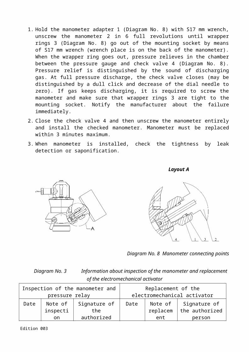
Diagram No. 9 Module’s vessel temperature-pressure curve for the fire-extinguishing agent HFC227ea (CF3CHFCF2) when the loading ratios are different (kg/m3)
Appendix No. 1 continued
Edition 003

Diagram No. 10 Module’s vessel temperature-pressure curve for the fire-extinguishing agent FK-5-1-12 (CF3CF2C(O)CF(CF3)2) when the loading ratios are different (kg/m3)
Appendix No. 2
Edition 003

LIST OF MEASURES:
Type of works:
Inspection of the vessel
Name of the inspecting company
License
Date of inspection
Review of the lock & release device
Hydraulic testing of the vessel
Loading with the fire-extinguishing agent:- type of the agent- mark of the agentMass of the fire-extinguishing agentTotal massDate of reloadingOperating pressure
Remarks (recommendations)
Implementing company:
Responsible Manager (Surname and name, signature):
Seal Seal Seal
Appendix No. 3
Edition 003

MAINTENANCE
Warranty Certificate No. _____________________________________
1. Warranty Certificate is valid within 24 months starting from the date of purchase. 2. The Manufacturer shall repair or replace joints of the product for free within the warranty
period provided that Paragraphs 7, 8, 9 of this Manual and requirements as follows are fulfilled: 2.1 – in accordance with paragraph 7.1.1 of the Labour Protection Regulatory Act 0.00-1.07-94
“Rules for design and safe operation of pressure vessels”, the Owner must provide safe labour conditions and serviceability of the modules. For the above purposes, it is necessary:
2.1.1 – to keep records of the company’s modules and their inspections which are both registered in a maintenance technical center and unliable to registration (copies are given to the manufacturer);
3. Cylinders are subject to exploitation, storage and transportation cording to instructions.3.1 – In the premises the modules must be installed at least 1 meter far from the heating radiators
and other heating appliances and 10 meters to furnaces and other heating appliances with open flame; 3.2 – The modules may be transported by all vehicles in the way which prevents the cargo from
moving, falling and collision. Transporting and storing the modules, it is required to protect the products from the atmospheric condensation, direct sunlight and corrosive mediums. The modules should be transported and stored within the temperature range minus 20°С - plus 50 °С;
3.3 – Do not drop and kick the module. 3.4 – Installing the module, do not take the pulverizer and manometer in hand in order to
save the module’s hermeticity.4. Warranty shall not be applied if: 4.1 – the modules are exploited improperly; 4.2 – the modules have been damaged due to improper transportation or storage;4.3 – maintenance, repair works or other interventions have been provided by unauthorized
persons;4.4 – requirements described in paragraph 2.1 and 3 have not been fulfilled; 4.5 – control seals are damaged or absent.
PACKING LIST
Edition 003

Name of components Type (article, number) Quantity
1. Module IMPULSE- ____(25-___-18)
2.Type of the supporting frame
3. Manometer and pressure relay РД-И60 serial number No.
4. Electromechanical activator EMA
5. Manual (passport)
6. Packing
Packed by:
_____________________________
Signature
Surname and initials
Seal
Date-Month-Year
NOTESEdition 003

_________________________________________________________________________________________________________________________________________________________________________________________________________________________________________________________________________________________________________________________________________________________________________________________________________________________________________________________________________________________________________________________________________________________________________________________________________________________________________________________________________________________________________________________________________________________________________________________________________________________________________________________________________________________________________________________________________________________________________________________________________________________________________________________________________________________________________________________________________________________________________________________________________________________________________________________________________________________________________________________________________________________________________________________________________________________________________________________________________________________________________________________________________________________________________________________________________________________________________________________________________________________________________________________________________________________________________________________________________________________________________________________________________________________________________________________________________________________________________________________________________________________________________________________________________________________________________________________________________________________________________________________________________________________________________________________________________________________________________________________________________________________________________________________________________________________________________________________________________________________________________________________________________________________________________________________________________________________________________________________________________________________________________________________________________________________________________________________________________________________________________________________________________________________________________________________________________________________________________________________________________________________________________________________________________________________________________________________________________________________________________________________________________________________________________________________________________________________________________________
Edition 003


![CATEGORY OF MIXED PLECTIC HODGE …The purpose of this article is to investigate the properties of the category of mixed plectic Hodge structures defined by Nekovář and Scholl [NS1]](https://img.pdfslide.tips/doc/110x75/5e44df3c57182d6ef358f344/category-of-mixed-plectic-hodge-the-purpose-of-this-article-is-to-investigate-the.jpg)