Embed Size (px)
Citation preview

GSK983M Milling CNC System
Connection Manual

GSK983M Milling Machine CNC System Connection Manual
Ⅰ
The operating manual describes all matters concerning the operation of the system in detail as much as possible. However, it is impractical to give particular descriptions of all unnecessary and/or unavailable works on the system due to the length limit of the manual, specific operations of the product and other causes. Therefore, the matters not specified herein may be considered impractical or unavailable.
This operating manual is the property of GSK CNC Equipment Co., Ltd. All rights reserved. It is against the law for any organization or single to publish or reprint this manual without the express written permission of GSK and the latter reserves the right to ascertain their legal liability.

GSK983M Milling Machine CNC System Connection Manual
Ⅱ
Company Profile
GSK CNC EQUIPMENT CO., LTD(GSK) , CNC Industry Base of South China, is responsible for the National High Technology Research and Development Program of China (863 Program): Moderate CNC Industrialization Key Technology. For ten years, we are exclusively engaged in research, Development, manufacture, sale, training and popularization of Machine Tool CNC system, Servo Motor and driver, and other mechanical products. Today, GSK has already expressed into a large-scale new high-tech enterprise that deals with research, teaching, working and trading. Our products support more than 60 domestic manufacturers of machine tools with after-sales service network through the country. With a yield in the lead in China from 2000 to 2005 in succession, GSK series products are in great demand in the domestic demand and have a ready sale in Southeast Asia at high performance-to-price ratio.
Field technical support services Field support services are available when you encounter a problem insolvable through telephone. GSK CNC Equipment Company Limited will designate a technical support engineer to the field to solve technical problems for you. Chinese version of all technical documents in Chinese and English languages is regarded as final.

GSK983M Milling Machine CNC System Connection Manual
Ⅲ
Foreword
Dear user, We are really grateful for your patronage and purchase of GSK983M milling CNC system, which is made by GSK CNC Equipment Co., Ltd.
This manual consists of two volumes. Volume I mainly describes the specifications and programming of the system while Volume II operations, all codes, parameters, I/O interfaces and other appendices.
! This system can only be operated by authorized and qualified personnel as improper operations may cause accidents. Please carefully read this operating manual before usage.
All specifications and designs herein are subject to change without further notice.
We are full of heartfelt gratitude to you for supporting us in the use of GSK’s products.

GSK983M Milling Machine CNC System Connection Manual
ⅰ
Content
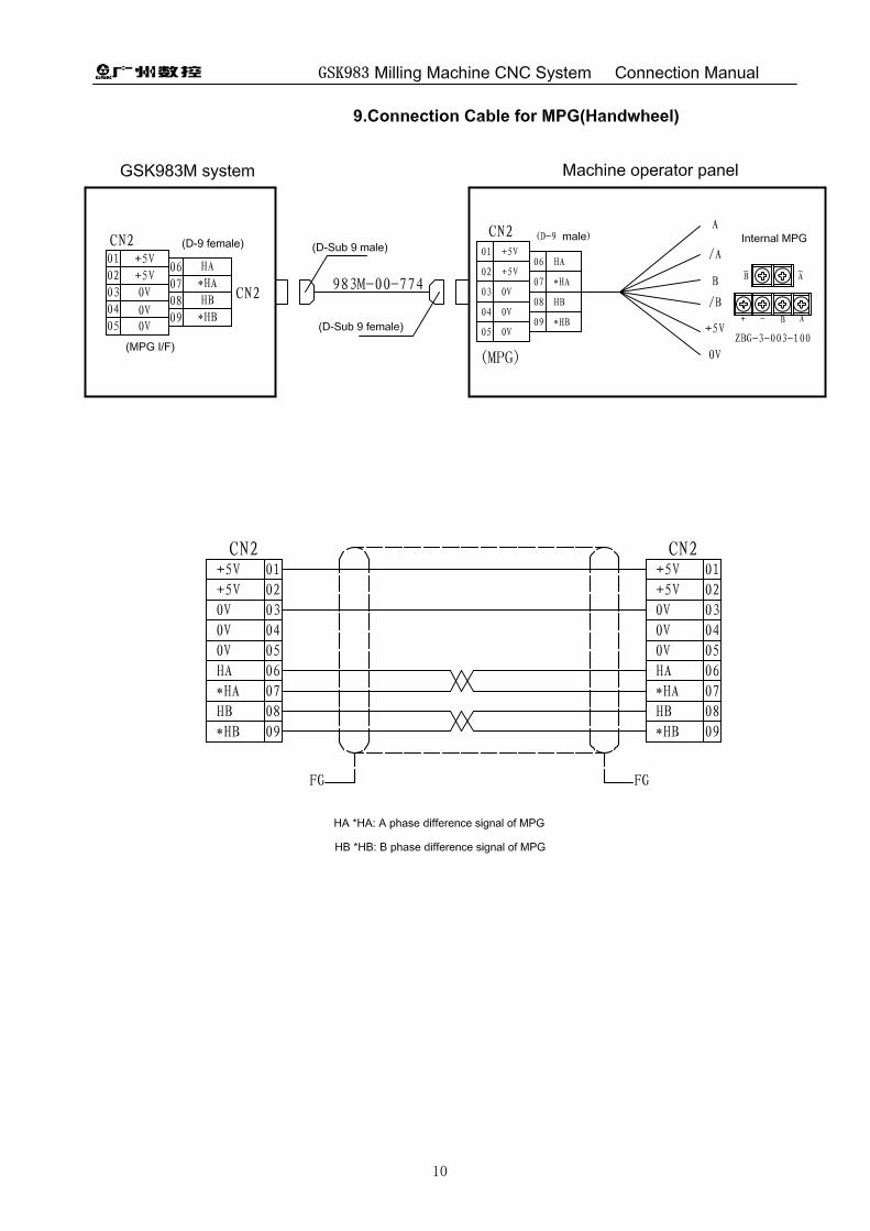
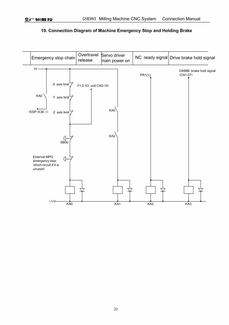
Precautions for Connection .................................................................................................................1 1. Interface Layout of the System........................................................................................................2 2. Interface Layout of CPU Board .......................................................................................................3 3. Interface Layout of Position Control Board......................................................................................4 4. Interface Layout of I/O Board ..........................................................................................................5 5. Interface Layout of MDI/LCD Panel.................................................................................................6 6. Interface Layout of Machine Operator panel ...................................................................................7 7. Connection Layout ..........................................................................................................................8 8. Connection Cables for Communication with PC(RS232) ................................................................9 9. Connection Cables for MPG (Handwheel) ....................................................................................10 10. External MPG(Handwheel) Connection 1: Internal Connection of Operator panel ......................11 11. External MPG(Handwheel) Connection 2: external MPG connection..........................................12 12 . Connection Cables for Keyboard ...............................................................................................13 13. Connection Cables for Display ....................................................................................................14 14. Communication Cable between Operator panel and System......................................................15 15. Cables for Connecting DA98B Drive ...........................................................................................16 16. Z Axis Connecting Holding Cable of DA98B Drive ......................................................................17 17. Cables for Spindle Frequency Changer ......................................................................................18 18. Cables for Connecting DAP01 Servo Spindle .............................................................................19 19. Connection Diagram of Machine Emergency Stop and Holding Brake .......................................20 20. External I/O Unit ..........................................................................................................................21 21. Communication Connection Cables for External I/O Unit and System........................................22 22. Definition for I/O input/output point ..............................................................................................23 Appendix 1: MV2.02A-16 PLC use....................................................................................................25 Appendix 2: Installation Dimension Diagram ................................................................................422

GSK983M Milling Machine CNC System Connection Manual
1
Precautions for Connection
1. Power should be supplied by isolating transformer.
2. Shells of the system parts and the machine must be securely grounded.
3. The system should be installed far away from place where the interference may occur (such as
converter, AC contactor, static generator, high voltage generator and subsection devices of
power line); and the space dimension around the system should also be complied with the
installation dimension described in the manual.
4. The environment around the system should conform to the requirements described in the
manual.
5. The signal cables and control cables of weak current should be distributed far away from the
place where there are strong current and strong electromagnetic interference; they should be
distributed straightly against interfering signal, otherwise, it easily receives the interfering
signal.
6. Interference suppression: Connect parallel RC loop to the two connector lugs of AC coil(Fig.1)
and the RC loop should be fixed as near as possible to the inductive load; connect reversely
parallel freewheeling diode at the two connector lugs of DC coil(Fig.2); connect parallel surge
absorber at the connector lugs of AC motor winding(Fig.3).
(Fig. 3)
KM
Surgeabsorber
3~
M
(Fig. 2)
(Fig. 1)
0V
+24V
AC220V


GSK983M Milling Machine CNC System Connection Manual
23
22. Definition for I/O input/output point
CN1 pin No. input
PLC address
Signal name
I/O CN2 pin No. input
PLC address
Signal name
I/O
1 32.0 *X+ limit I 1 48.0 I 2 32.1 *X- limit I 2 48.1 I 3 32.2 I 3 48.2 I 4 32.3 I 4 48.3 I 5 32.4 I 5 48.4 I 6 32.5 *X machine zero
return deceleration I 6 48.5
I
7 32.6 I 7 48.6 I 8 32.7 I 8 48.7 I 9 33.0 *Y+ limit I 9 49.0 I 10 33.1 *Y- limit I 10 49.1 I 11 33.2 I 11 49.2 I 12 33.3 I 12 49.3 I 13 33.4 I 13 49.4 I 14 33.5 *Y machine zero
return deceleration I 14 49.5
I
15 33.6 I 15 49.6 I 16 33.7 I 16 49.7 I 17 34.0 *Z+ limit I 17 35.0 *+L4limit I 18 34.1 *Z- limit I 18 35.1 *-L4 limit I 19 34.2 I 19 35.2 I 20 34.3 I 20 35.3 I 21 34.4 I 21 35.4 I 22 34.5 *Z machine zero
return deceleration I 22 35.5 *DEC4 machine zero
return deceleration I
23 34.6 I 23 35.6 I 24 34.7 I 24 35.7 I 25 38.0 I 25 39.0 I 26 38.1 I 26 39.1 I 27 38.2 I 27 39.2 I 28 38.3 I 28 39.3 I 29 38.4 *Emergency
stop input I 29 39.4
I
30 38.5 I 30 39.5 I 31 38.6 I 31 39.6 I 32 38.7 I 32 39.7 I 33 0V 33 0V 34 0V 34 0V 35 0V 35 0V 36 0V 36 0V 37 24V 37 24V 38 24V 38 24V 39 24V 39 24V 40 24V
40 24V

GSK983M Milling Machine CNC System Connection Manual
24
CN3 pin No. output
PLC address
Signal definition I/O CN4 pin No. output
PLC address
Signal definition I/O
1 0.0 1 3.0 2 0.1 2 3.1 3 0.2 3 3.2 4 0.3 4 3.3 5 0.4 5 3.4 6 0.5 6 3.5 7 0.6 7 3.6 8 0.7 8 3.7 9 1.0 9 4.0
10 1.1 10 4.1 11 1.2 11 4.2 12 1.3 12 4.3 13 1.4 13 4.4 14 1.5 14 4.5 15 1.6 15 4.6 16 1.7 16 4.7 17 2.0 17 2.4 18 2.1 18 2.5 19 2.2 19 2.6 20 2.3 20 2.7 21 0V 21 0V 22 0V 22 0V 23 0V 23 0V 24 0V 24 0V 25 24V 25 24V 26 24V
26 24V
Note: The unmarked signals for CN1~CN4 is defined by PLC and also programming. The marked
signals can’t be changed.
GSK983M Milling Machine CNC System Connection Manual
25
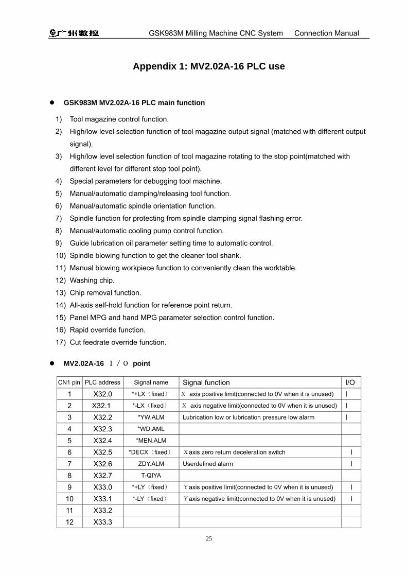
Appendix 1: MV2.02A-16 PLC use
GSK983M MV2.02A-16 PLC main function
1) Tool magazine control function.
2) High/low level selection function of tool magazine output signal (matched with different output
signal).
3) High/low level selection function of tool magazine rotating to the stop point(matched with
different level for different stop tool point).
4) Special parameters for debugging tool machine.
5) Manual/automatic clamping/releasing tool function.
6) Manual/automatic spindle orientation function.
7) Spindle function for protecting from spindle clamping signal flashing error.
8) Manual/automatic cooling pump control function.
9) Guide lubrication oil parameter setting time to automatic control.
10) Spindle blowing function to get the cleaner tool shank.
11) Manual blowing workpiece function to conveniently clean the worktable.
12) Washing chip.
13) Chip removal function.
14) All-axis self-hold function for reference point return.
15) Panel MPG and hand MPG parameter selection control function.
16) Rapid override function.
17) Cut feedrate override function.
MV2.02A-16 I/O point
CN1 pin PLC address Signal name Signal function I/O
1 X32.0 *+LX(fixed) X axis positive limit(connected to 0V when it is unused) I 2 X32.1 *-LX(fixed) X axis negative limit(connected to 0V when it is unused) I 3 X32.2 *YW.ALM Lubrication low or lubrication pressure low alarm I 4 X32.3 *WD.AML 5 X32.4 *MEN.ALM 6 X32.5 *DECX(fixed) Xaxis zero return deceleration switch I 7 X32.6 ZDY.ALM Userdefined alarm I 8 X32.7 T-QIYA 9 X33.0 *+LY(fixed) Yaxis positive limit(connected to 0V when it is unused) I
10 X33.1 *-LY(fixed) Yaxis negative limit(connected to 0V when it is unused) I 11 X33.2 12 X33.3

GSK983M Milling Machine CNC System Connection Manual
26
13 X33.4 14 X33.5 *DECY(fixed) Yaxis zero return deceleration switch I 15 X33.6 16 X33.7 17 X34.0 *+LZ(fixed) Zaxis positive limit(connected to 0Vwhen is it unused) I 18 X34.1 *-LZ(fixed) Zaxis negative limit(connected to 0Vwhen is it unused) I 19 X34.2 20 X34.3 21 X34.4 22 X34.5 *DECZ Zaxis zero return deceleration switch I 23 X34.6 24 X34.7 25 X38.0 GR1.M 26 X38.1 GR2.M 27 X38.2 GR3.M 28 X38.3 GR4.M 29 X38.4 *ESP(fixed) Emergency stop I 30 X38.5 TRLCK.I Releasing tool(in-position check) I 31 X38.6 TCLCK.I Clamping tool(in-position check) I 32 X38.7 CKST Releasing/clamping tool button I 33 0V 34 0V 35 0V 36 0V 37 +24V 38 +24V 39 +24V 40 +24V
CN2 pin PLC address Signal name Signal function I/O1 X48.0
2 X48.1
3 X48.2
4 X48.3
5 X48.4
6 X48.5
7 X48.6
8 X48.7
9 X49.0
10 X49.1
11 X49.2

GSK983M Milling Machine CNC System Connection Manual
27
12 X49.3
13 X49.4 T0.I
14 X49.5 TCN.I Tool count signal(214.2=1 count switch ON) I
15 X49.6 TFN.I Tool magazine forward in-position(228.7=1 in-position) I
16 X49.7 TBK.I Tool magazine backward in-position(229.4=1 in-position) I
17 X35.0 *+L4(fixed) 4th axis positive limit I
18 X35.1 *-L4(fixed) 4th axis negative limit I
19 X35.2
20 X35.3
21 X35.4
22 X35.5 *DEC4(fixed) 4th zero return deceleration I
23 X35.6 Index table clamping in-position
24 X35.7 Index table releasing in-position
25 X39.0
26 X39.1
27 X39.2
28 X39.3 UNSOR.M
29 X39.4 SOR.M Spindle orientation in-position check I
30 X39.5 *SRDY Spindle alarm input signal I
31 X39.6 *ZSP Spindle zero speed check I
32 X39.7 *SAR Spindle speed arrival check I
33 0V
34 0V
35 0V
36 0V
37 +24V
38 +24V
39 +24V
40 +24V
CN3 pin PLC address Signal name Signal function I/O
1 Y0.0 GR1.O
2 Y0.1 GR2.O
3 Y0.2 GR3.O
4 Y0.3 GR4.O
5 Y0.4 TFR.O Tool magazine forward O
6 Y0.5 TBK.O Tool magazine backward O
7 Y0.6 M19.O Spindle orientation O
8 Y0.7 TRL.M Releasing tool O
9 Y1.0 TC.O Tool magazine CCW O
10 Y1.1 TCC.O Tool magazine CW O

GSK983M Milling Machine CNC System Connection Manual
28
11 Y1.2 SPZD Spindle brake
12 Y1.3 CLN.O Cooling(coolant)pump output O
13 Y1.4 LUB.O Lubrication pump output O
14 Y1.5 OR.T Overtravel release O
15 Y1.6 M03 Spindle CCW O
16 Y1.7 M04 Spindle CW O
17 Y2.0 RED.ALL Light house red light output O
18 Y2.1 YEL.ALL Light house yellow light output O
19 Y2.2 GRE.ALL Light house green light output O
20 Y2.3
21 0V
22 0V
23 0V
24 0V
25 +24V
26 +24V
CN4 pin PLC address Signal name Signal function 1 Y3.0 GZD.L Machine working light O
2 Y3.1 CLN2.O Wash chip valve output O
3 Y3.2 CFN.O Spindle blow output O
4 Y3.3 CHIP.CW Chip removal CCW output O
5 Y3.4 CLN-2O Workpiece blow output O
6 Y3.5 CHIP.CCW Chip removal CW output O
7 Y3.6
8 Y3.7
9 Y4.0
10 Y4.1
11 Y4.2
12 Y4.3
13 Y4.4
14 Y4.5
15 Y4.6
16 Y4.7
17 Y2.4 MTRST System reset output O
18 Y2.5 4UCLPO Index table release output
19 Y2.6 4-CLPO Index table clamp output
20 Y2.7
21 0V
22 0V
23 0V

GSK983M Milling Machine CNC System Connection Manual
29
24 0V
25 +24V
26 +24V
Note: I stands for the input signal and O for the output signal in the above list.
I/O interface input signal:
1) logic selection of input point
Whether the high level or low level is enabled is set by the jumper lead (S1……S8) on the I/O
board, S1-S8: the high level is enabled when it is connected to 0V; the low level is enabled
when it is connected to +24V. The low level of jumper lead on I/O is enabled.
S1-S8 setting
+24V0VHigh level is enabledLow level is enabled
0V +24V
32.0-32.7 is defined by S1;
33.0-33.7 is defined by S2;
34.0-34.7 is defined by S3;
35.0-35.7 is defined by S4;
38.0-38.7 is defined by S5;
39.0-39.7 is defined by S6;
48.0-48.7 is defined by S7;
49.0-49.7 is defined by S8.
Note: High/low level setting of S1-S8 is related to PLC program logic, considering whether
PLC program logic is correct or not when the setting is changed. For MV2.02A-16 PLC
version, the low level for S1-S7 is fixed to be enabled and cannot be changed into that
the high level is enabled, otherwise PLC control does not normally run. Only S8, the
setting of high/low level is enabled according to the output of tool magazine proximity
switch.
2) Signal with *
The signal with * should be the normally-closed contact(connected to 0V) when it is turned
on.
MV2.02A-16 PC parameters

GSK983M Milling Machine CNC System Connection Manual
30
600 7 6 5 4 3 2 1 0
3001 X+-ZRN ATC.ZN TBFTCNDP SP.ALM TRLTCL. ZSP.C SAR.C ABS-1
Bit7 X+-ZRN:X axis zero return self-protecting direction selection.
0:zero return self-protecting in positive direction.
1:zero return self-protecting in negative direction.
Bit6 ATC.ZN: whether the CNC system is matched with the tool magazine system.
0:no tool magazine function.
1:have tool magazine function.
Bit5 TBFTCNDP: it is the output signal level selection when tool magazine forward/backward signal,
and the tool magazine counter switch is conducted. (the setting should be
consistent with the actual electricity element).
0: When the signal for tool magazine forward/backward in-position and the switch of tool
magazine counter are connected, the output signal is 0V.
1: When the signal for tool magazine forward/backward in-position, and the switch of tool
magazine counter are connected, the output signal is 24V. Note: When the signal for tool magazine forward/backward in-position, and the switch of tool
magazine counter are connected, and the output signal is 24V, S8 jumper lead is
connected to 0V besides the parameter should be set.
Bit4 SP.ALM: Whether CNC executes checking the spindle alarm input signal *SRDY.
0: Do not check the spindle alarm input signal.
1: Check the spindle alarm input signal.
Bit3 TRLTCL.: Whether the clamping tool in-position input signal TCLCK.I and releasing tool
in-position input signal TRLCK.I is checked when the spindle rotates.
0: Do no check.
1: Check.
Bit2 ZSP.C : Whether the spindle zero speed input signal is checked when the tool is clamped/
released.
0: The spindle zero speed signal *ZSP is not check when the tool is clamped/released.
1: The spindle zero speed signal is checked. The tool releasing signal can output when the
spindle zero speed signal arrives in Auto mode.
Bit1 SAR.C :Whether S instruction check the spindle speed arrival input signal.
0 : Do not check the spindle speed arrival signal *SAR. S function output is completed.
1 : Check the spindle speed arrival input signal. The S instruction does not complete until the *SAR signal arrives.
Bit0 ABS-1: Whether LCD menu switch manual absolute ON/OFF is shielded.

GSK983M Milling Machine CNC System Connection Manual
31
0: Manual absolute menu switch is shielded, menu ABS ON/OFF is disabled.
1: Manual absolute value function is enabled, menu ABS ON/OFF is enabled.
601 7 6 5 4 3 2 1 0
3002 T-STPL
G
H>MP
G
Bit7 T-STPLG:Tool magazine pallet rotation/stop position selection.(set correctly when it is
matched with tool magazines with different types)
0:When the pallet rotates the in-position, the counter proximity switch output is not
conducted.(Fig. a).
1:When the pallet rotates the in-position, the counter proximity switch output is conducted.(Fig. b).
Fig. a
Switch is the noninductive conductionwhen the tool pallet in-position stops
Fig. b
Counting promixity switch
Switch is the inductive conductionwhen the tool pallet in-position stops
Bit5 H>MPG :Control MPG selection.
0: panel MPG control.
1: handle MPG control.
602 7 6 5 4 3 2 1 0
3003 CHIP.CC CHIP.C ZIDY.C YW.C
Bit5 CHIP.CC : whether the CW function of the chip removal is enabled.
0 : disabled.
1 : enabled.
Bit4 CHIP.C: whether the CCW function of the chip removal is enabled.
0 : disabled.
1 : enabled.
Bit3 ZIDY.C: The run program and instruction whether check the userdefined alarm input signal
ZDY.ALM.
0 : Do not check ZDY.ALM signal. CNC can automatically run when the input signal
ZDY.ALM=0.

GSK983M Milling Machine CNC System Connection Manual
32
1 : Check ZDY.ALM signal. CNC does not automatically run and alarms when the input
signal ZDY.ALM=0.
Bit0 YW.C : The run program and instruction whether check the lubrication oil high/low or pressure
high/low input signal.
0: Do not check lubrication low/pressure low alarm input signal. CNC can automatically run
when there is no input signal YW. ALM=1.
1: Check lubrication low/pressure low alarm input signal. CNC can not automatically run
when there is no input signal YW. ALM=1.
603 7 6 5 4 3 2 1 0
3004 T-TZ1
Bit6 T-TZ1: Whether the CNC enters the tool magazine mechanical debugging state.(tool
magazine mechanical debugging parameter).
0: The CNC does not enter the tool magazine mechanical debugging state.(it is set to 0
when the tool magazine normally runs.)
1: The CNC enters the tool magazine mechanical debugging state.
(Note: when the mechanical position is debugged, Bit 6=1, NC alarm indicator flashes,
and CNC cannot enter Auto mode but enter MDI mode. After regulating the
mechanical position of tool magazine and clamping tool position of spindle, PC
parameter #3004.6 is set to 0, otherwise, the run program faults.
PC parameter
number
Parameter function
1001 Time setting of first supply oil after it is turned on firstly. Unit: 0.5
millisecond.
1002 Time setting of stopping supply oil. Unit: 0.5 millisecond.
1003 Time setting of every supply oil after first supply oil. Unit: 0.5
millisecond.
1010 Time setting of checking tool clamping signal interrupt when the
spindle is rotating. Unit: 0.5 millisecond.
1011 Flashing time interval of NC alarm indicator when debugging tool
magazine(PC603 Bit6 is set to 1).
2001 Setting of total tool amount controlled by tool magazine program.
2101 Setting of current tool number of tool magazine.
MV2.02A-16 PLC M codes

GSK983M Milling Machine CNC System Connection Manual
33
M3 spindle CCW
M4 spindle CW
M5 spindle stop
M6 T×× tool change
M8 cooling pump ON
M9 cooling pump OFF
M19 spindle orientation
M54: releasing tool
M55: clamping tool
M65: tool magazine forward
M66: tool magazine backward M84: index table release
M85 index table clamp
Tool magazine function
1) Total tool amount
For 983M MV2.02A -16 PLC software, there are total 16 tools. If a new tool is added, the
internal setting value of PLC is modified. Using MV2.02A-×× PLC software, user can change
the setting value of PC parameter from its external but the software cannot be used
normally.
2) Command tool change
1. For MV2.02A-16 PLC software, the tool change is executed by using M6 Txx in Auto
and MDI mode.
2. NC prompts No. 200 alarms when the commanded tool number is more than the total
tool amount.
3. NC prompts No. 200 alarms when the commanded tool number is 0.
4. The tool change instruction is neglected when the commanded tool number is equal to
the current tool number.
3) Tool change operation
1. In Auto and MDI mode, after M6 Txx instruction is executed, the program judge whether
the input tool number instruction meets the tool change conditions, if it meets, the
spindle stop turning to execute the spindle orientation.
2. Z axis returns to the first reference point.
3. Z axis returns to the second reference point.
4. The tool magazine forwards to clip the tool on the current spindle.
5. Gas valve releasing tool.
6. Z axis rises to the first reference point to make the tool escape from the spindle.

GSK983M Milling Machine CNC System Connection Manual
34
7. Rotating pallet to the commanded tool number.
8. Z axis falling down to the second reference point.
9. Clamping tool.
10. Retract from the tool magazine and the tool change completion.
The whole tool change process is completed by CNC, i.e user input the instruction M6
4) Tool change items
1. Do not lock machine lock when the tool change is executed.
2. The tool pot of tool magazine corresponding to the current spindle cannot install the
tool.
5) Tool magazine notes:
1. Check and set the second reference point again after changing the CNC master board
or regulating the position of Z axis deceleration limit switch.
2. must set NC parameter #320=6, otherwise the tool magazine does not run normally.
3. The second reference point of Z axis is set by NC parameter 161, and the setting value
cannot be changed after debugging the machine, otherwise the tool magazine is
damaged.
4. The system macro variable #509 is exclusive to tool magazine, and cannot be used
and changed by user.
5. Macro program for tool change must be No. O9001 memory program.
6. The tool magazine can forward after Z axis return to the first or second reference point.
6) Troubleshoots for emergent stop, power-off, reset and alarm.
1. When the tool change is executed in MDI or Auto mode and the tool magazine is in the
forward limited position, the spindle descends to the 2nd reference point position, the tool
is clamped, when the tool magazine is not retracted(the system variable #509=0), and the
emergency stop, power-on, alarm, reset appears, the machine tool should be in the state
of debugging (PC parameter #3004.6=1), the tool magazine is retracted by M66 in MDI
mode, and the machine tool escapes from the debugging state.(note: at this time, the
spindle cannot be released and the tool magazine retracts in Z direction).
2. The tool change is commanded in MDI mode or is executed in Auto mode, the tool
magazine is in the forward limited position, the spindle has released the tool, (system
macro variable #509=1)when Z axis does not raise or the tool pallet does not rotate after
it raises and the emergence stop, power-off, alarm or reset appears, the machine tool
should enter the state of debugging(PC parameter #3004.6=1), M54 is commanded to
release the spindle, and Z axis reaches the safety position in Manual mode and then M66
is commanded to retract from the tool magazine, and it normally use when the machine
tool retracts from the state of debugging.
3. The tool change is commanded in MDI mode or is executed automatically, the tool

GSK983M Milling Machine CNC System Connection Manual
35
magazine is in the forward limited position, Z axis reaches the first reference point. When
the tool magazine is rotating, the emergency stop, power-off, alarm, or reset appears, the
tool number of current double digit display is not consistent with the actual tool number, if
the tool is executed continuously, the machine should be in the debugging state(PC
parameter #3004.6=1), M66 is commanded to retract the tool magazine, T** is
commanded to rotate the tool pallet one time to ensure there is no tool in the position
corresponding the current spindle, and then set PC parameter #2101 to be the current
tool pot number, it can be normally used when the machine escapes from the state of
debugging.
7) Alarm for tool change
In Auto and MDI mode, after the tool change is executed by M6 Txx, No. 200 alarms, which
indicates the commanded tool number exceeds the setting of total tool amount or the pallet
has not arrived to the correction position or the machine auxiliary function is locked.
8) Tool number display
The current tool number is displayed on the double digit display of operator panel in
decimal.
9) Spindle releasing/clamping tool function:
1. The releasing/clamping tool function must be executed when the spindle stops.
2. In Manual mode, the releasing/clamping tool button is pressed, the releasing tool
signal outputs; the tool is clamped after the button is released.
3. In Auto and MDI mode, pressing the releasing/clamping tool button is disabled. Use M
code to release/clamp tool. M55: clamping tool; M54: releasing tool.
4. PC parameter relative to releasing/clamping tool: set PC parameter #3001.3bit=1, the
releasing/clamping tool check is enabled. M55 clamping tool instruction is not
completed until TRLCK.I=1, M54 releasing tool instruction is not completed until
TRLCK.I=1.
Debugging tool magazine
1) Setting of tool magazine debugging state
To conveniently debug the concentric between the tool pot position and spindle, and Z axis
clipping tool position, set the tool magazine debugging PC parameter. Setting PC
parameter #3004.6=1 to enter tool magazine debugging mode, the interlock condition of
tool magazine forwarding, backing and rotating are ignored, and the tool magazine is
debugged. 2) Parameter setting before debugging tool magazine
1. set PC parameter #2001 to the total tool amount.
2. set PC parameter #2101 to the current tool number.

GSK983M Milling Machine CNC System Connection Manual
36
3. set NC parameter #300.5 bit to 0. 3) Use in the state of tool magazine debugging
1. When the tool magazine is in the state of debugging, the CNC system cannot run the
Auto mode but other operation modes.
2. When the tool magazine is in the state of debugging, the tool magazine forwards by
M64 in MDI mode.
3. The tool magazine backs by M66 in MDI mode.
4. The pallet rotates to the commanded tool number by commanding T** in MDI mode.
5. When the tool magazine is in the state of debugging, releasing spindle can move the
machine in the limit position of tool forwarding.
4)Tool magazine debugging notes
1. When the tool magazine is in the state of debugging, the safety position of tool
magazine is controlled by debugger to avoid the bump between the tool magazine
and the machine.
2. The CNC prompts the tool magazine is in the state of debugging when NC ALARM
indicator flashes. After the tool magazine is debugged, PC parameter #3004.6 bit is
set to 0 to escape from the debugging state, and the tool magazine control is
executed in Auto mode.
Zero return of machine feed axis
1) Axis zero return self-protection
For 983M MV2.02A-16 PLC, press +X ,+Y,+Z,+4 to realize each axis to return to the
reference point without setting PC parameter in Zero Return mode, and the direction button
will automatically hold in the course of zero return. After the reference point return is
completed, the zero point indicators on each axis will light. Press -X ,-Y,-Z,-4, emergency
stop button or RESET to cancel the zero return operation
2) Setting of zero return in X negative direction
983M MV2.02A-16 PLC is used for the machining center with the tool magazine control
function, zero return of X axis is executed in negative direction, the position of zero return
deceleration switch is reverse to the common milling machine(self-protection direction of
zero return can be selected by PC parameter #3001.7, the zero return in negative direction
can be executed when NC parameter #12.0 is set to 1).
3) Zero return and DNC mode
Tool magazine retracts is enabled in Zero Return and DNC mode, and tool magazine
forwards is disabled in Zero Return and DNC mode.
Spindle function

GSK983M Milling Machine CNC System Connection Manual
37
983M MV2.02A-16 PLC supports S4 bit digit A (analog voltage), and does not execute
multi-speed spindle motor control and output mechanical gear shifting signal and execute the
gear shifting in-position check.
Spindle speed is directly specified by S ××××(4 bit digit) and its max. analog voltage is ±10V.
Spindle orientation function
When the machine is matched with servo spindle driver, press ORIENTATION in Manual mode or
command M19 in Auto/MDI mode, the system outputs the orientation start signal to the servo driver,
and it transmits the completion signal after the driver completes the spindle orientation, and then the
CNC receives the orientation completion signal and M19 instruction completes.
Spindle alarm
The check spindle alarm input signal can be set when PC parameter #3001.4 is set to 1, the
MACHINE ALARM indicator on the machine operator panel lights and the system is in the state of
emergency stop and stops all output when the alarm appears.
Emergency stop alarm The MACHINE ALARM indicator on the machine operator panel lights and all output stop when the
system alarms for emergency stop.
MPG 1) 983M MV2.02A-16 PLC MPG is for the one on the machine operator panel. The default
step is X1=0.001mm when the system is delivered. User can select X10=0.01mm,
X100=0.1mm according to the requirements.
2) When the machine is controlled by MPG of the external handle box, the axis selection and
the override signal of the handle box are connected to CN2 of machine operator panel, A/B
pulse signal of MPG is connected to CN2 of CPU board of the system, and the emergency
stop switch is connected in series to the emergency stop chain. See External MPG
Connection in GSK983M Connection Manual.
Note: (PC parameter #3002.5 must be set to 1 to enable external MPG control is enabled.)
Rapid override
In Manual mode, press RAPID and the indicator on the machine panel lights and the rapid override
is selected byX1, X10, X100; in Auto mode, the rapid override can be switched byX1/F0, X
10/150%, X100/100% .

GSK983M Milling Machine CNC System Connection Manual
38
Corresponding relationship: X1→F0 X10→50% X100→100%, RAPID press key is enabled in
Manual and Zero Return mode, and disabled when it overtravels and the tool magazine is in the
forward limit switch position.
Cooling function
In any operation modes, press COOLING on the machine panel to control the cooling pump ON/OFF.
Press it and it becomes ON, press it again and it becomes OFF, it is ON in Manual mode, and OFF by
commanding M09 in Auto MDI mode. It is ON by commanding M8 in Auto MDI mode, is OFF by
pressing COOLING and commanding M09
Washing chip function
In any operation modes, press WASHING CHIP on the machine operator panel to control the
washing chip ON/OFF. Press it and it becomes ON, press it again and it becomes OFF.
Spindle blowing
In Manual mode, when the tool is released, the spindle blowing is ON, when the tool is clamped, the
spindle blowing is OFF. In Auto or MDI mode, M54 is commanded and the tool is released, the
spindle blowing is ON, M55 is commanded and the tool is clamped, the spindle blowing is OFF.
Workpiece blowing
In any operation modes, press BLOWING WORKPIECE to control the blowing workpiece ON/OFF.
Press it and it becomes ON, press it again and it becomes OFF.
Machine light/chip removal
Machine light/chip removal key can be selected by parameter’s setting, when PC parameter:
#3003.5=1 #3003.4=0: it is the machine light function in any operation mode. Press MACHINE
LIGHT/CHIP REMOVAL and it becomes ON, press it again and it becomes OFF. The light is ON
when the system resets and appears the emergency stop.
#3003.5=0 #3003.4=1: it is the chip removal CCW function. Press MACHINE LIGHT/CHIP
REMOVAL and the chip removal CCW outputs.
#3003.5=0 #3003.4=0: it is the chip removal CW function. Press MACHINE LIGHT/CHIP
REMOVAL and the chip removal CW outputs. The chip removal stops output when the system
resets and emergently stops.

GSK983M Milling Machine CNC System Connection Manual
39
#3003.5=1 #3003.4=1:there is no output.
Overtravel release/tool release indicator
Press OVERTRAVEL , I/O PLC address 1.5 outputs 0V, and the output stops after the key is released.
User can externally connect with relay used for closing the emergency stop chain which is broken by
overtravel.
Index table clamping/releasing control
Whether the index table clamping/releasing control function is used is set by PC parameter 3002 Bit4.
when it is used, and there is no clamping/releasing in-position signal, the 4th axis cannot run.
Command M84 to output the index table releasing signal; command M85 to output the index table
clamping signal. The clamping/releasing signal is output through IO unit.
MV2.02A-16 PLC alarm list
MV2.02A-16PLC alarm list
Alarm Cause Troubleshooting
1.The red light house is ON
2. MACHINE ALARM on the
panel is ON
3.The press key is out of order
and does not shift the operation
modes
1.The spindle servo
driver alarms
2.The level setting of
driver alarm is
mistake
3.*SRDY alarm
connection line is
turned off
1. Resolve the spindle servo alarm
2.Check the level setting of driver
alarm signal
3.Check *SRDY alarm connection
line
1. The red light house is ON
2. NC ALARM on the panel is
ON
3. The press key is out of order
and does not shift the operation
modes
1. The emergency
stop connection
line is turned off
2. The emergency
stop button is
pressed
3. The CNC system
is fault
1.Check whether the emergency
stop button is pressed
2.Check whether the emergency
stop connection line is turned off
3.Change the CNC system
1. The red light house is ON
2. FEED HOLD on the panel is
ON
3.The system does not execute
1.Lubrication oil low
alarms
2. *YW.ALM
connection is turned
1. Add the lubrication to eliminate
the alarm
2. Check *YW.ALM connection line
3. Check whether *YW.ALM alarm

GSK983M Milling Machine CNC System Connection Manual
40
Auto and MDI mode off.
3. *YW.ALM
connection is
connected with +24V
level is mistake
4. Check whether the setting of
No.3003.3 parameter is mistake.
No.200 alarms in tool change
1. Specified T number
exceeds the total
amount
2.The tool pallet is not
in-position.
3. The auxiliary
function is locked.
4. T code is not
specified after M6 is
executed.
1.Check whether the setting of total
tool amount is mistake
2.Execute the next tool change in
the tool magazine debugging mode.
3.Check whether the setting of
T-STPLG bit is mistake.
1. The red light house is ON.
2. FEED HOLD on the panel is
ON
3. The system does not execute
Auto and MDI mode
1. User. *ZDY. ALM
connection line is cut
off
2. *ZDY.ALM
connection line is
connected to +24V
1.Eliminate the userdefined alarm
source
2.Check *ZDY. ALM connection line
3.Whether *ZDY.ALM alarm level is
mistake.
4.Whether the setting of No.3003.3
parameter is mistake
MV2.02A-16 PLC tool change macro program(reference)
% :9001 N0010 G04 X5 N0020 #19=#1032 N0025 IF[#19 EQ 0] GO TO 320 N0030 M5 N0040 G04 X5 N0045 IF[#1032 EQ 0] GO TO 320 N0050 IF[#4120 GE #19] GO TO 320 N0070 IF[#4120 EQ 0] GO TO 320 N0090 IF[#4120 EQ #1032] GO TO 460 N0100 M19 N0110 G04 X5 N0120 #19=#0 N0130 IF[#509 EQ 1] GO TO 330 N0140 G21 G49 G30 G91 Z0 N0160 M65 N0170 G04 X1.0 N0190 M54 N0200 #509=1 N0210 G21 G49 G28 G91 Z0

GSK983M Milling Machine CNC System Connection Manual
41
N0220 M60 N0230 G04 X1.0 N0240 G21 G49 G30 G91 Z0 N0250 M55 N0255 #509=0 N0260 G04 X1 N0270 M66 N0310 GO TO 460 N0320 #3000=200 N0330 G21 G49 G28 G91 Z0 N0335 M54 N0340 #509=1 N0350 M65 N0360 G04 X1.0 N0370 M60 N0380 G04 X1.0 N0390 G21 G49 G30 G91 Z0 N0400 M55 N0410 #509=0 N0420 M66 N0460 M99 %

GSK983M Milling Machine CNC System Connection Manual
42
Appendix 2: Installation Dimension Diagram
CD1(LCD)
CN3(KEY)(232) (MPG)
CN1 CN2
CC2
(Y/Z axis)CV2
(OP)
(X axis)CV1
CC1(IO)
(Z/SP axis)CV3
EFFFSD2
SD1
+24
HF
(LCD)
CN4 OFF
ON PRM.WT
(5th/SP axis)CV4
(4th axis)
-
PR1
+
+24V0V
CP1(+24V IN)
PR
WD
CV5
CC3(DNC)
Inst
alla
tion
dim
ensi
on o
f the
mai
n ca
bine
t


GSK983M Milling Machine CNC System Connection Manual
46
GSK983M Connection Manual version upgrade list
No. Date Version No. upgrade Upgrade content 1 2007-4-17 Version 4 from 3 PLC MV2.02A-16 is upgraded from MV2.0A-16 and the
Connection Maunal is changed as follows: 1. All MV2.0A-16 renamed to MV2.02A-16. 2. Add the Index Table Clamping/Releasing In-Position Input Appendix 1IO point X35.6, X35.7.
3.Add the Index Table Clamping/Releasing Output in 1IO point Y2.5, Y2.6. 4. Add the following items in Appendix 1 Tool magazine:5) Tool change note: when the unexpected causes (emergency stop, power-down and so on) cause that the tool pot of tool magazine which corresponds to the current spindle is installed with the tool, the macro variable #509 can be set to1 to change the second reference point path of the next tool change and avoid bumping tool. 5. Add the Index Table Clamping/Releasing Control in Appendix I. 6.Have modified Tool Change Reference Macro Program in Appendix 1.

Add: No.52, 1st . Street, Luochong North Road, Luochongwei, Guangzhou, 510165, China
Website: http://www.gsk.com.cn E-mail: [email protected] Tel: 86-20-81796410/81797922 Fax: 86-20-81993683
All specification and designs are subject to change without notice May 2007/Edition 4
May 2007/Printing 1