Embed Size (px)
Citation preview

I n t e g r a t e d C o n t r o l S o l u t i o n s & E n e r g y S a v i n g s
NO POWER & SIGNAL CABLES
TOGETHER
READ CAREFULLY IN THE TEXT!
Technical leafl et
Foglio istruzioni
pCO5 controllo elettronicoelectronic controller


Indice / Contents / Inhalt / Sommaire
Foglio istruzioni 3
Technical leafl et 27


5+0500040ML - 1.1 - 20.09.2010
INTRODUZIONEpCO5 è un controllo elettronico a microprocessore compatibile sia a livello hardware che software con la famiglia pCO3. Sviluppato da CAREL nel rispetto delle normativa europea RoHS, per offrire molteplici applicazioni nel settore del condizionamento dell’aria e della refrigerazione. Assicura la più assoluta versatilità di applicazione, consentendo di realizzare prodotti specifi ci su richiesta del cliente.pCO5 è dedicato all’esecuzione del programma di regolazione ed è dotato del set di morsetti necessari alla connessione verso i dispositivi (compressori, ventilatori..). Il programma e i parametri sono memorizzati su FLASH-MEMORY e su E2prom, consentendo il loro mantenimento anche in caso di mancanza di alimentazione (senza la necessità di una batteria di mantenimento).
pCO5 permette la connessione alla rete locale pLAN (pCO Local Area Network) e può essere collegato, oltre che ad altri pCO5, anche a tutti gli altri controllori del pCO sistema e a tutti i terminali della famiglia pGD. Ogni controllore in rete pLAN può scambiare qualsiasi variabile, digitale o analogica, a seconda del programma applicativo utilizzato. Possono essere collegate fi no a 32 unità, tra controllori pCO e terminali, in modo da condividere le informazioni in maniera effi cace.pCO5 ha due seriali RS485 aggiuntive built-in rispetto ad altri pCO, una per il FieldBus e l’altra per supervisione/teleassistenza (BMS). Il collegamento verso la linea seriale BMS con il protocollo di comunicazione CAREL o Modbus®, secondo lo standard RS485, viene realizzato tramite l’inserimento sul pCO5 di una scheda seriale opzionale oppure tramite la seriale built-in.È possibile, mediante altre schede opzionali, la connessione a supervisore con standard diversi da RS485. Infi ne le seriali FieldBus, mediante scheda opzionale o built-in, offrono la connessione verso dispositivi controllati di campo (ad esempio: valvole, espansioni I/O pCOe, driver esterno per valvola elettronica). Nella taglia pCO5 Medium è possibile una nuova soluzione integrata: la versione con driver valvola EVDEvo built-in, singolo o twin.
Versioni disponibili: • SMALL, MEDIUM, LARGE, EXTRALARGE (uscite digitali con contatti normalmente aperti), DRIVER VALVOLA;• con o senza terminale built-in;• con memoria NAND fl ash aggiuntiva;• con o senza uscite digitali relè a stato solido (SSR) 24Vac/Vdc o 110/230 Vac/Vdc;• con o senza USB Master e Slave.
Upload del programma applicativoIl programma applicativo può essere scaricato nella memoria fl ash in diversi modi:1. con chiave:
• smart key PCOS00AKY0;• USB pen drive;
2. con personal computer PC:• porta seriale 485 (28,8 kbps e 115.2 kbps) mediante adattatore USB-485 “CVSTDUTLF0”;• USB slave.
Per l’upload tramite PC è necessario utilizzare il programma “pCO Manager” disponibile gratuitamente sul sito ksa.carel.com.
AlimentazioneNell’installazione utilizzare un trasformatore di sicurezza in Classe II di 50 VA (100 VA nelle versioni con Driver Valvola integrato) e un fusibile da 2,5 AT per l’alimentazione di un solo controllore pCO5. Si raccomanda di separare l’alimentazione del controllo pCO5 e terminale (o più pCO5 e terminali) dall’alimentazione del resto dei dispositivi elettrici (contattori ed altri componenti elettromeccanici) all’interno del quadro elettrico. Qualora il secondario del trasformatore sia posto a terra, verifi care che il conduttore di terra sia collegato al morsetto G0. Attenersi a ciò per tutti i dispositivi connessi al pCO5. Se si alimentano più controlli pCO5 collegati, assicurarsi che siano rispettati i riferimenti G e G0 (il riferimento G0 deve essere mantenuto per tutte le schede).In caso di utilizzo della rete pLAN e per ulteriori specifi cazioni consultare il manuale pCO Sistema CAREL cod. +030220335.
Opzioni FieldBus Opzioni BMS
485 opto isolata PCO100FD10 CAN idronica PCOS00HBB0tLAN PCO100TLN0 485/Modbus® PCOS004850MP-BUS Belimo PCO100MPB0 modem PCO100MDM0modem PCOS00FD20 scheda Ethernet/BACnet PCO1000WB0CAN idronica PCOS00HBF0 scheda BACnet MS/TP PCO1000BA0Konnex PCOS00KXF0 Konnex PCOS00KXB0
LonWorks FTT10 PCO10000F0LonWorks FTT10 profi lo chiller standard PCO10001F0
italiano

6+0500040ML - 1.1 - 20.09.2010
ConnettoriEsempio di codifi ca: PCO5CON***, vedi tabella seguente per descrizione:
PCO5CON * * 00= a vite1= a molla
S= smallM= mediumL= largeZ= extra large 2= medium con driver valvola
DisplayBuilt-in tipo PGD1 (132x64 pixel), con tastiera retroilluminata.
CARATTERISTICHE TECNICHE
Caratteristiche meccanichedimensioni versione SMALL inseribile su 13 moduli DIN, 110 x 227.5 x 60 mm
versione MEDIUM, LARGE, EXTRALARGE e DRIVER VALVOLA inseribili su 18 moduli DIN, 110 x 315 x 60 mmmontaggio su guida DIN
Contenitore plastico• agganciabile su guida DIN secondo norme DIN 43880 e CEI EN 50022;• materiale: tecnopolimero;• autoestinguenza: V2 (secondo UL94) e 850 °C (secondo IEC 60695);• prova biglia: 125 °C;• resistenza alle correnti striscianti: 250 V;• colore: grigio RAL7035;
Caratteristiche elettrichealimentazione (controllore con terminale connesso) Versioni senza Driver Valvola integrato:
24 Vac +10/-15% 50…60 Hz e 28…36 Vdc +10/-20%; assorbimento massimo 45 VA/20 WVersione con driver valvola integrato:24 Vac +10/-15% 50…60 Hz;assorbimento massimo: 80 VA/35 W
morsettiera con connettori maschio/femmina estraibili, tensione max 250 Vac; sez. cavo: min. 0,5 mm2 - max 2,5 mm2
CPU H8SX1651, 32 bit, 44 MHzmemoria (su FLASH MEMORY) 2+2 MB. Disponibile anche un’ulteriore memoria di 32 MB su Nand Flash.memoria dati (RAM statica) 512 kB organizzata a 16 bit (296 kB Bios; 216 kB applicativo).memoria dati parametri 13 kB organizzata a 16 bit (limite max: 100.000 scritture per locazione di memoria) e
ulteriori 32 kB di E2prom (non visibili dalla pLAN)durata ciclo utile (applicazioni media complessità) 0,2 s (tipico)orologio con batteria di serieprecisione orologio 100 ppmcaratteristiche batteria batteria di tipo “bottone” al litio cod. CR2430 tensione 3 Vdc (dimensioni 24x3 mm)

7+0500040ML - 1.1 - 20.09.2010
Ingressi digitali tipo ID1...ID18 optoisolati (contatto in tensione); B4, B5, B9, B10 non optoisolati (contatto pulito)numero massimo ingressi in tensione optoisolati 8: SMALL; 14: MEDIUM e EXTRALARGE; 18: LARGE. Secondo le combinazioni riportate
qui sotto:n. ingr. optoisolati a 24 Vac
50/60 Hz o 24 Vdcn. ingr. optoisolati a 24 Vac/Vdc
o 230 Vac (50/60 Hz)totale
ingressiSMALL 8 nessuno 8MEDIUM/EXTRALARGE
12 2 14
LARGE 14 4 18numero massimo ingressi a contatto pulito non optoisolati
2: SMALL, MEDIUM e EXTRALARGE (B4 e B5);4: LARGE (B4, B5, B9, B10)
Classifi cazione dei circuiti di misura (CEI EN 61010-1) Categoria I (J5, J7, J20) 24 Vac/Vdc - Categoria III (J8, J19) 230 VacCorrente ingressi digitali puliti (B4, B5, B9, B10) 5 mACorrente ingressi digitali in tensione 24 Vac 5 mACorrente ingressi digitali in tensione 230 Vac 5 mA
AVVERTENZE: - ingressi digitali IDH alimentati a 230 Vac 50/60 Hz (10/-15%) protetti con un unico fusibile da 500 mAT; - i due ingressi a 230/24 Vac presenti su J8 e J12, hanno il medesimo polo comune e quindi saranno entrambi a 24 Vac/Vdc o 230 Vac. Esiste il doppio isolamento tra i due ingressi e il resto del controllo. - in caso di ingresso digitale in continua (Vdc), è indifferente collegare il + o il - al comune (IDC1). - la portata del contatto esterno degli ingressi digitali deve essere almeno pari a 5 mA.Nota: separare quanto più possibile i cavi dei segnali delle sonde e degli ingressi digitali dai cavi relativi ai carichi induttivi e di potenza, per evitare possibili disturbi elettromagnetici.
Caratteristiche Ingresso Digitale Veloce (B4 e B5)Quando sono confi gurati come ingressi digitali veloci, B4 e B5 sono caratterizzati dalla possibilità di misurare un segnale con una frequenza massima di 2 KHz con risoluzione di ±1 Hz. Questo è reso possibile, poichè il BIOS rende disponibili al Software Applicativo due coppie di variabili che contengono il conteggio dei passaggi per lo zero del segnale all’ingresso e la relativa frequenza in Hz.
Ingressi analogici conversione analogica A/D converter a 10 bit CPU built-intipo universale: (ingressi B1, B2, B3, B6, B7, B8) sensore di temperatura NTC CAREL (-50T90 °C; R/T 10 k a 25 °C),
NTC HT 0T150 °C, tensione: 0…1 Vdc, 0…5 V raziometrici o 0…10 Vdc, corrente: 0…20 mA o 4…20 mA, selezionabili via software. Resistenza di ingresso in 0…20 mA= 100 passivo: (ingressi B4, B5, B9, B10) sensore di temp. NTC CAREL (vedi tipo universale), PT1000 (-100T200 °C; R/T 1000 a 0°C) o input digitale pulito (5 mA), selezionabili via software;
numero massimo 5: SMALL; 8: MEDIUM e EXTRALARGE; 10: LARGEcostante di tempo per ogni ingresso
0,5 s
precisione ± 0,3 % del fondo scalaclassifi cazione dei circuiti di misura (CEI EN 61010-1)
Categoria I
impedenza di ingresso NTC 10 k4...20 mA 100 0...1 V 100 k0...5 V 20 k0...10 V 12,7 kPT1000 10 k
AVVERTENZA: per l’alimentazione di eventuali sonde attive, è possibile utilizzare i 21 Vdc disponibili sul morsetto +Vdc (J2), la corrente massima erogabile è di 150 mA protetta contro i corti circuiti. Per l’alimentazione delle sonde raziometriche 0…5 V si utilizzano i +5VREF (Imax: 60 mA) presenti nel morsetto J24. Utilizzare esclusivamente queste tensioni per alimentare le sonde attive collegate a pCO5
Uscite analogichetipo 0…10 Vdc optoisolate su Y1, Y2, Y3, Y4, Y5 e Y6 / taglio di fase su Y3 e Y4numero massimo 4: SMALL, MEDIUM e EXTRALARGE ; 6: LARGEalimentazione esterna 24 Vac/Vdc su VG(+), VG0(-)risoluzione 8 bitcarico massimo 1,5 k (7 mA)precisione ± 2 % del fondo scala sulle uscite: Y1, Y2, Y3, Y4, Y5 e Y6
italiano
8+0500040ML - 1.1 - 20.09.2010
AVVERTENZE: • Ad un’uscita analogica di tipo 0...10 Vdc si possono collegare in parallelo altre uscite dello stesso tipo, oppure una tensione esterna.
La tensione risultante sarà quella maggiore. Non è garantito il corretto funzionamento nel caso si colleghino attuatori con ingresso in tensione. Alimentare le uscite analogiche VG-VG0 con la stessa tensione presente su G-G0: Connettere G0 a VG0 e G a VG.Questo è valido sia per alimentazioni in alternata sia in continua.
• Nel caso di uscite a taglio di fase (PWM) si fa notare che il sincronismo (zero crossing) è prelevato da G/G0 e solo con alimentazione 24 Vac e non Vdc.
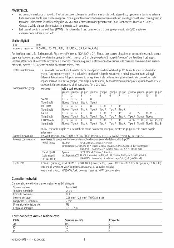
Uscite digitali tipo relènumero massimo 8: SMALL; 13: MEDIUM; 18: LARGE; 29: EXTRALARGE
Per i collegamenti si fa riferimento alle Fig. 3 e 4 (riferimento NO*, NC* e C*). Si nota la presenza di uscite con contatto in scambio tenute separate (ovvero senza poli condivisi tra uscite distinte). I gruppi da 3 uscite prevedono 2 morsetti “comuni” per facilitare il cablaggio.Prestare attenzione alla corrente circolante nei morsetti comuni in quanto la stessa non deve superare la corrente nominale di un singolo morsetto, ovvero 8 A. Corrente minima di contatto relè: 50 mA.
Distanza isolamento Le uscite relè hanno differenti caratteristiche che dipendono dal modello di pCO5. Le uscite sono suddivisibili in gruppi. Tra gruppo e gruppo (cella-cella della tabella) vi è doppio isolamento e quindi possono avere voltaggi differenti. Esiste inoltre il doppio isolamento tra ogni terminale delle uscite digitali e il resto del controllore.I relè appartenenti ad uno stesso gruppo (celle singole nella tabella) hanno isolamento principale e quindi devono essere sottoposti alla stessa tensione di alimentazione (24 o 230 Vac).
Composizione gruppi versione relè a pari isolamentogruppo 1
gruppo 2
gruppo 3
gruppo 4
gruppo 5
gruppo 6
gruppo 7
gruppo 8
gruppo 9
gruppo 10
gruppo 11
SMALLTipo di relè
1…3 4…6 7 8 - - - - - - -Tipo A Tipo A Tipo A Tipo A
MEDIUMTipo di relè
1…3 4…6 7 8 9…11 12 13 - - - -Tipo A Tipo A Tipo A Tipo A Tipo A Tipo A Tipo A
LARGETipo di relè
1…3 4…6 7 8 9…11 12 13 14 15 16...18 -Tipo A Tipo A Tipo A Tipo A Tipo A Tipo A Tipo A Tipo A Tipo A Tipo A
EXTRALARGE Tipo di relè
1…3 4…6 7 8 9…11 12 13 14...16 17...20 21...24 25...29Tipo A Tipo A Tipo A Tipo A Tipo A Tipo A Tipo A Tipo B Tipo B Tipo B Tipo B
NOTA: i relè nelle singole celle della tabella hanno isolamento principale, mentre tra gruppi di celle hanno doppio isolamento.
Contatti in scambio 1: SMALL (relè 8); 3: MEDIUM e EXTRALARGE (relè 8, 12 e 13); 5: LARGE (relè 8, 12, 13, 14 e 15)Potenza commutabile avvertenza: le uscite relè hanno caratteristiche diverse a seconda del modello di pCO5
relè di tipo A tipo relè: SPDT, 2000 VA, 250 Vac, 8 A resistiviomologazioni pCO5: UL873: 2,5 A resistivi, 2 A FLA, 12 A LRA, 250 Vac, C300 pilot duty (30.000 cicli) EN 60730-1: 2 A resistivi, 2 A induttivi, cos= 0,6, 2(2) A (100.000 cicli)
relè di tipo B (solo modelli EXTRALARGE)
tipo relè: SPDT, 1250 VA, 250 Vac, 5 A resistivi omologazioni pCO5: UL873: 1 A resistivi, 1 A FLA, 6 A LRA, 250 Vac, D300 pilot duty (30.000 cicli) EN 60730-1: 1 A resistivi, 1 A induttivi, cos= 0,6, 1(1) A (100.000 cicli)
Uscite SSR 1: SMALL (uscita 7); 2: MEDIUM e EXTRALARGE (uscite 7 e 12); 3 o 4: LARGE (uscite 7, 12 e 14 oppure 7, 12, 14 e 15)tensione di lavoro: 24 Vac/Vdc; potenza massima: 10 W, carico resistivotensione di lavoro: 110/230 Vac/Vdc; potenza massima: 10 W, carico resistivo
Connettori estraibiliCaratteristiche elettriche dei connettori estraibili utilizzati:
Tipo connettore Passo 5,08Tensione nominale 250 VCorrente nominale 12 ASezione del cavo 0,25 mm2 - 2,5 mm2 (AWG: 24 a 12)Lunghezza di spellatura 7 mmDimensione fi lettatura vite M3Coppia di serraggio 0,5-0,6 Nm
Corrispondenza AWG e sezione cavoAWG Sezione (mm2) Corrente20 0,5 215 1,5 614 2,5 8
9+0500040ML - 1.1 - 20.09.2010
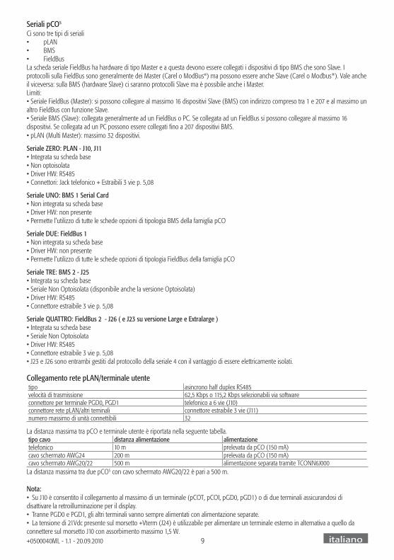
Seriali pCO5
Ci sono tre tipi di seriali• pLAN• BMS• FieldBusLa scheda seriale FieldBus ha hardware di tipo Master e a questa devono essere collegati i dispositivi di tipo BMS che sono Slave. I protocolli sulla FieldBus sono generalmente dei Master (Carel o ModBus®) ma possono essere anche Slave (Carel o Modbus®). Vale anche il viceversa: sulla BMS (hardware Slave) ci saranno protocolli Slave ma è possibile anche i Master.Limiti: • Seriale FieldBus (Master): si possono collegare al massimo 16 dispositivi Slave (BMS) con indirizzo compreso tra 1 e 207 e al massimo un altro FieldBus con funzione Slave. • Seriale BMS (Slave): collegata generalmente ad un FieldBus o PC. Se collegata ad un FieldBus si possono collegare al massimo 16 dispositivi. Se collegata ad un PC possono essere collegati fi no a 207 dispositivi BMS. • pLAN (Multi Master): massimo 32 dispositivi.
Seriale ZERO: PLAN - J10, J11 • Integrata su scheda base• Non optoisolata• Driver HW: RS485• Connettori: Jack telefonico + Estraibili 3 vie p. 5,08
Seriale UNO: BMS 1 Serial Card • Non integrata su scheda base• Driver HW: non presente• Permette l’utilizzo di tutte le schede opzioni di tipologia BMS della famiglia pCO
Seriale DUE: FieldBus 1 • Non integrata su scheda base• Driver HW: non presente• Permette l’utilizzo di tutte le schede opzioni di tipologia FieldBus della famiglia pCO
Seriale TRE: BMS 2 - J25 • Integrata su scheda base• Seriale Non Optoisolata (disponibile anche la versione Optoisolata)• Driver HW: RS485 • Connettore estraibile 3 vie p. 5,08
Seriale QUATTRO: FieldBus 2 - J26 ( e J23 su versione Large e Extralarge ) • Integrata su scheda base• Seriale Non Optoisolata• Driver HW: RS485• Connettore estraibile 3 vie p. 5,08• J23 e J26 sono entrambi gestiti dal protocollo della seriale 4 con il vantaggio di essere elettricamente isolati.
Collegamento rete pLAN/terminale utentetipo asincrono half duplex RS485velocità di trasmissione 62,5 Kbps o 115,2 Kbps selezionabili via softwareconnettore per terminale PGD0, PGD1 telefonico a 6 vie (J10)connettore rete pLAN/altri teminali connettore estraibile 3 vie (J11)numero massimo di unità connettibili 32
La distanza massima tra pCO e terminale utente è riportata nella seguente tabella.tipo cavo distanza alimentazione alimentazionetelefonico 10 m prelevata da pCO (150 mA)cavo schermato AWG24 200 m prelevata da pCO (150 mA)cavo schermato AWG20/22 500 m alimentazione separata tramite TCONN6J000
La distanza massima tra due pCO5 con cavo schermato AWG20/22 è pari a 500 m.
Nota:• Su J10 è consentito il collegamento al massimo di un terminale (pCOT, pCOI, pGD0, pGD1) o di due terminali assicurandosi di disattivare la retroilluminazione per il display. • Tranne PGD0 e PGD1, gli altri terminali vanno sempre alimentati con alimentazione separate.• La tensione di 21Vdc presente sul morsetto +Vterm (J24) è utilizzabile per alimentare un terminale esterno in alternativa a quello da connettere sul morsetto J10 con assorbimento massimo 1,5 W.
italiano

10+0500040ML - 1.1 - 20.09.2010
VERSIONE CON DRIVER VALVOLA ESPANSIONE ELETTRONICANella taglia pCO5 Medium è possibile una nuova soluzione integrata: la versione con driver EVDEvo built-in, singolo o twin. La scheda driver è alloggiata all’interno di pCO5 nella postazione prevista per gli ingressi / uscite della taglia Large, ecco perché è disponibile solo nella taglia pCO5 Medium (non Small, non Large, non ExtraLarge) e non necessita di alimentazione esterna..
Il driver integrato, replica in tutte le funzioni hardware e logiche il controllo “EVD Evolution TWIN” , pilotando cioè in modo indipendente una o due valvole di espansione elettronica motore passo-passo bipolare. L’unica differenza tra le due versioni è l’assenza dei relè di uscita. Per tutta la logica di controllo valvola, setup e installazione si rimanda quindi al manuale EVDEvo (codice + 0300005IT).
Allo stesso modo di EVDEvo, anche per pCO5 il driver interno è disponibile in versione CAREL e Universal. I modelli “Universal” permettono di pilotare oltre alle valvole di espansione elettronica CAREL anche quelle di diversi costruttori (vedi tabella sottostante), i modelli CAREL pilotano invece solamente le valvole CAREL.
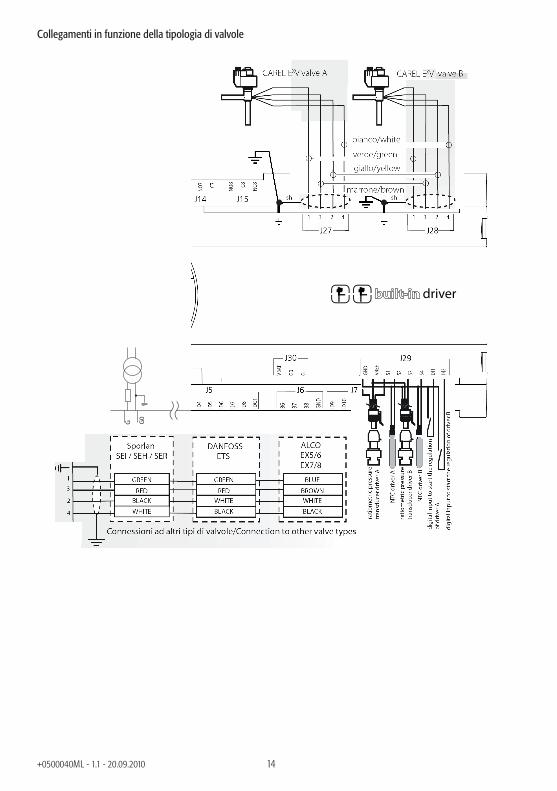
Tabella compatibilità valvoleCostruttore Modelli compatibiliCAREL E*V****ALCO EX4; EX5; EX6; EX7; EX8 330 Hz (consigliato da CAREL); EX8 500 Hz (da specifi che ALCO)SPORLAN SEI 0.5-11; SER 1.5-20; SEI 30; SEI 50; SEH 100; SEH175Danfoss ETS 12.5-25B; ETS 50B; ETS 100B; ETS 250; ETS 400CAREL Due EXV CAREL collegate insieme SPORLAN SER(I) G, J, K
Comunicazione seriale e programmazione
La comunicazione tra pCO5 e il suo driver EVDEvo integrato è realizzata internamente utilizzando la porta seriale Fieldbus2. La porta seriale FieldBus2 (J26), è però elettricamente isolata dalla linea seriale del driver: questo assicura che in caso di guasti esterni sulla linea connessa a FBus2, il driver interno possa continuare a funzionare indipendentemente e correttamente.La confi gurazione del driver può essere effettuata esclusivamente attraverso l’applicazione di pCO5 sviluppata con 1Tool, non sono previsti possibili display esterni dedicati al EvdEVO.
Nell’ambiente di sviluppo 1Tool, è presente un modulo per la gestione del EVDEvo: per la gestione del driver interno lo stesso modulo andrà utilizzato come si abbia da gestire un EVDEvo esterno collegato alla porta FBus2.
pCO5 Medium gestisce la scheda driver integrata come un EVDEvo Twin esterno collegato alla Field Bus 2. A livello software applicativo 1Tool, il driver valvola va quindi collegato alla FBus2. Per tale motivo, eventuali altri dispositivi collegati fi sicamente alla FBus (J26) dovranno avere lo stesso protocollo di comunicazione (CAREL Standard Master o Modbus® Master), lo stesso baude-rate, bit stop e parità.
Da tenere presente che il driver interno ha indirizzo 198 (il default di EVDEvo), quindi eventuali altri dispositivi collegati al J26 devono avere indirizzo diverso da 198. Possono essere collegati alla FieldBus 1 (scheda opzionale), EVDEvo esterni senza i vincoli.

11+0500040ML - 1.1 - 20.09.2010
Esempio di applicazione:
Al fi ne di assicurare le performance di scambio dati tra il driver EvdEVO e il pCO5, si raccomanda durante la fase di sviluppo dell’applicativo 1Tool, nel caso ci siano dispositivi connessi alla porta FBus2 (morsetto J26) con protocollo Modbus®, di valutare il numero di variabili scambiate dalla intera linea seriale.
Collegamenti elettrici
• Al fi ne di semplifi care l’installazione di pCO5 con EvdEVO, l’alimentazione G-G0 fornita alla base del pCO5 è collegata internamente, mediante un cavo schermato, anche al EvdEVO: il driver non va quindi alimentato.
• Si raccomanda di tenere separati i cavi degli ingressi digitali e analogici dal cavo di alimentazione della valvola. Tutti gli ingressi analogici e digitali sono riferiti alla massa GND, quindi l’applicazione, anche temporanea, di tensioni superiori a ±5 V a questi collegamenti può causare un danno irreversibile al driver. Essendo GND la massa comune per tutti gli ingressi è preferibile replicarla in morsettiera.

12+0500040ML - 1.1 - 20.09.2010
Caratteristiche tecnicheCollegamento motore cavo schermato a 4 poli CAREL codice E2VCABS*00, oppure cavo schermato a 4 poli AWG22 Lmax =10
m, oppure cavo schermato a 4 poli AWG14 Lmax 50 mCollegamento ingressi digitali Ingresso digitale da azionare con contatto pulito o transistor verso GND.
Corrente di chiusura 5mA; Lunghezza massima < 10 mSonde lunghezza massima 10 m o inferiore a 30 m con cavo schermato
S1 sonda pressione raziometrica (0…5 V)
risoluzione 0,1 % fs errore di misura: 2% fs massimo; 1% tipico
sonda pressione elettronica (4…20 mA)
risoluzione 0,5 % fs; errore di misura: 8% fs massimo; 7% tipico
sonda pressione raziometrica combinata (0…5 V)
risoluzione 0,1 % fs errore di misura: 2 % fs massimo; 1 % tipico
Ingresso 4…20 mA (max. 24 mA)
risoluzione 0,5 % fs errore di misura: 8 % fs massimo; 7 % tipico
S2 NTC bassa temperatura 10 k a 25 °C, -50T90 °C
errore di misura: 1°C nel range -50T50 °C; 3 °C nel range +50T90 °C
NTC alta temperatura 50 k a 25 °C, -40T150 °C
errore di misura: 1,5 °C nel range -20T115 °C, 4 °C nel range esterno a -20T115 °C
NTC combinata 0 k a 25 °C, -40T120 °C
errore di misura: 1°C nel range -40T50 °C; 3 °C nel range +50T90 °C
ingresso 0…10 V (max 12 V) risoluzione 0,1% fs errore di misura: 9% fs massimo; 8% tipicoS3 sonda pressione raziometrica
(0…5 V):risoluzione 0,1 % fs errore di misura: 2% fs massimo; 1% tipico
sonda pressione elettronica (4…20 mA)
risoluzione 0,5 % fs; errore di misura: 8% fs massimo; 7% tipico
sonda pressione raziometrica combinata (0…5 V)
risoluzione 0,1 % fs errore di misura: 2 % fs massimo; 1 % tipico
Ingresso 4…20 mA (max. 24 mA)
risoluzione 0,5 % fs errore di misura: 8 % fs massimo; 7 % tipico
S4 NTC bassa temperatura 10 k a 25 °C, -50T105 °C;
errore di misura: 1 °C nel range -50T50 °C; 3°C nel range 50T90 °C
NTC alta temperatura 0 k a 25 °C, -40T150 °C
rrore di misura: 1,5 °C nel range -20T115 °C; 4 °C nel range esterno a -20T115 °C
NTC combinata 10 k a 25 °C, -40T120 °C
errore di misura 1 °C nel range -40T50 °C; 3 °C nel range +50T90 °C
Alimentazione sonde attive (VREF)
uscita programmabile : +5 Vdc+/-2% o 12 Vdc+/-10%
Esempi di codici CAREL
PCO5000000A20: PCO5 MEDIUM + EVD EVO EMBEDDED FOR 2 CAREL EXVPCO50000U0C20: PCO5 MEDIUM + USB + NAND + EVD EVO EMBEDDED FOR 2 CAREL EXVPCO50000U0C60: PCO5 MEDIUM + USB + NAND + EVD EVO EMBEDDED FOR 2 UNIV. EXVPCO50000U0F20: PCO5 MEDIUM + USB+NAND+PGD1 +EVD EVO EMBEDDED FOR 2 CAREL EXV

13+0500040ML - 1.1 - 20.09.2010
Schema di collegamento e segnalazioni
driver
Connettori valvola J27 e J28: 1 = verde 3 = marrone 2 = giallo 4 = bianco• Collegare al faston la calza del cavo schermato della valvola e connettere a terra.• G0 va collegato a terra sul secondario del trasformatore.
Led di segnalazione: A (giallo) = Chiusura valvola A (J27) B (verde) = Apertura valvola A (J27) C (giallo) = Chiusura valvola B (J28) D (verde) = Apertura valvola B (J28)• Lampeggiano se la valvola è in movimento.• Accesi se la valvola è alle rispettive estremità.
14+0500040ML - 1.1 - 20.09.2010
Collegamenti in funzione della tipologia di valvole
driver
G G0

15+0500040ML - 1.1 - 20.09.2010
Altre caratteristichecondizioni di immagazzinamento -40T70 °C, 90% UR non condensantecondizioni di funzionamento -25T60 °C, 90% UR non condensantegrado di protezione IP20, IP40 nel solo frontalinoinquinamento ambientale 2classe secondo la protezione contro le scosse elettriche da integrare su apparecchiature di Classe I e/o II nelle versioni senza driver
valvola, Classe I nelle versioni con driver valvola.PTI dei materiali per isolamento PCB: PTI250; insulation material: PTI 175periodo delle sollecitazioni elettriche delle parti isolanti lungotipo azioni 1C; 1Y per versioni a SSRtipo disconnessione o microinterruzione microinterruzionecategoria di resistenza al calore e al fuoco categoria D (UL94 - V2)immunità contro le sovratensioni categoria IIcaratteristiche di invecchiamento (ore di funzionamento) 80.000n. cicli di manovra operazioni automatiche 100.000 (EN 60730-1); 30.000 (UL 873)classe e struttura del software Classe Acategoria di immunità al surge (CEI EN 61000-4-5) Categoria IIIIl dispositivo non è destinato ad essere tenuto in mano quando alimentato
Certifi cazione di ProdottoSicurezza elettrica EN 60730-1, EN 60730-2Compatibilita elettromagnetica Versioni senza driver valvola: EN 61000-6-1, EN 61000-6-2, EN 61000-6-2/EC, EN 61000-6-2/IS1, EN
61000-6-3, EN 61000-6-4; EN 55014-1, EN 55014-2, EN 55014-2/EC, EN 55014-2/A1, EN 55014-2/IS1, EN 55014-2/A2Versioni con driver valvola: EN 61000-6-1, EN 61000-6-2, EN 61000-6-2/EC, EN 61000-6-2/IS1, EN61000-6-3, EN 61000-6-4
AVVERTENZE• per applicazioni soggette a forti vibrazioni (1,5 mm pk-pk 10/55 Hz) si consiglia di fi ssare tramite fascette i cavi collegati al pCO5 a
circa 3 cm di distanza dai connettori;• per lunghezze superiori a 10 m, ad eccezione dei carichi relè e degli ingressi digitali 230 Vac, i cavi devono essere schermati con lo
schermo connesso a terra;• in ambiente domestico (EN55014), nelle versioni senza driver valvola, il cavo di collegamento tra pCO5 e il terminale e le altre seriali
deve essere schermato e connesso a terra in entrambi i lati;• l’installazione deve essere eseguita secondo le normative e legislazioni vigenti nel paese di utilizzo dell’apparecchiatura;• per motivi di sicurezza l’apparecchiatura deve essere alloggiata all’interno di un quadro elettrico, in modo che l’unica parte
raggiungibile sia il display e la tastiera comando;• tutte le connessioni in bassissima tensione (Ingressi analogici e digitali a 24 Vac/Vdc, uscite analogiche, connessioni bus seriali,
alimentazioni) devono avere un isolamento rinforzato o doppio rispetto alla rete;• per qualsiasi malfunzionamento non tentare di riparare l’apparecchio, ma rivolgersi al centro di assistenza CAREL;• assicurarsi che la temperatura interna al quadro dove è installato pCO5 non superi le condizioni di funzionamento.
ACCESSORIPCOS00AKY0 smart key pCO Sistema0907877AXX ferrite esterna per cavo alimentazione pCO5
S90CONN002 cavo di collegamento per terminali pGD L= 0,8 mS90CONN000 cavo di collegamento per terminali pGD L= 1,5 mS90CONN001 cavo di collegamento per terminali pGD L= 3 m
16+0500040ML - 1.1 - 20.09.2010
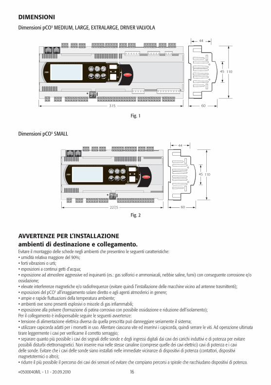
DIMENSIONI
Dimensioni pCO5 MEDIUM, LARGE, EXTRALARGE, DRIVER VALVOLA
11045
315 60
44
Fig. 1
Dimensioni pCO5 SMALL
227,5
11045
60
44
Fig. 2
AVVERTENZE PER L’INSTALLAZIONEambienti di destinazione e collegamento.Evitare il montaggio delle schede negli ambienti che presentino le seguenti caratteristiche:• umidità relativa maggiore del 90%;• forti vibrazioni o urti;• esposizioni a continui getti d’acqua;• esposizione ad atmosfere aggressive ed inquinanti (es.: gas solforici e ammoniacali, nebbie saline, fumi) con conseguente corrosione e/o ossidazione;• elevate interferenze magnetiche e/o radiofrequenze (evitare quindi l’installazione delle macchine vicino ad antenne trasmittenti);• esposizioni del pCO5 all’irraggiamento solare diretto e agli agenti atmosferici in genere;• ampie e rapide fl uttuazioni della temperatura ambiente;• ambienti ove sono presenti esplosivi o miscele di gas infi ammabili;• esposizione alla polvere (formazione di patina corrosiva con possibile ossidazione e riduzione dell’isolamento);Per il collegamento è indispensabile seguire le seguenti avvertenze:• tensione di alimentazione elettrica diversa da quella prescritta può danneggiare seriamente il sistema;• utilizzare capicorda adatti per i morsetti in uso. Allentare ciascuna vite ed inserirvi i capicorda, quindi serrare le viti. Ad operazione ultimata tirare leggermente i cavi per verifi carne il corretto serraggio;• separare quanto più possibile i cavi dei segnali delle sonde e degli ingressi digitali dai cavi dei carichi induttivi e di potenza per evitare possibili disturbi elettromagnetici. Non inserire mai nelle stesse canaline (comprese quelle dei cavi elettrici) cavi di potenza e i cavi delle sonde. Evitare che i cavi delle sonde siano installati nelle immediate vicinanze di dispositivi di potenza (contattori, dispositivi magnetotermici o altro);• ridurre il più possibile il percorso dei cavi dei sensori ed evitare che compiano percorsi a spirale che racchiudano dispositivi di potenza.
17+0500040ML - 1.1 - 20.09.2010
• evitare di avvicinarsi con le dita ai componenti elettronici montati sulle schede per evitare scariche elettrostatiche (estremamente dannose) dall’operatore verso i componenti stessi;• separare l’alimentazione delle uscite digitali dall’alimentazione di pCO5;• scollegare dall’alimentazione il controllo prima di eseguire qualsiasi tipo di manutenzione o montaggio.• qualora l’apparecchio venga impiegato in un modo non specifi cato dal costruttore, la protezione prevista dall’apparecchio potrebbe essere compromessa.
pCO5 non fornisce protezione contro il corto circuito ed il sovraccarico, si prescrive quindi di installare adeguati mezzi di protezione (fusibile 2.5 AT) nelle linee di alimentazione e nelle linee di ingresso digitali a 230 Vac (fusibile 500 mAT).
pCO5 non è un’apparecchiatura che garantisce la sicurezza elettrica, ma semplicemente il funzionamento adeguato: per evitare che a seguito di un cortocircuito i quadri elettrici prendano fuoco, il cliente deve installare adeguati mezzi d’interruzione elettromeccanica sulle linee interessate (fusibili o quant’altro).Inoltre il tipo di software non garantisce la sicurezza elettrica.
NO POWER & SIGNAL CABLES
TOGETHER
READ CAREFULLY IN THE TEXT!
ATTENZIONE: separare quanto più possibile i cavi delle sonde e degli ingressi digitali dai cavi dei carichi induttivi e di potenza per evitare possibili disturbi elettromagnetici. Non inserire mai nelle stesse canaline (comprese quelle dei quadri elettrici) cavi di potenza e cavi di segnale.
1
34
2
REGOLE PER LO SMALTIMENTO• Non smaltire il prodotto come rifi uto solido urbano ma smaltirlo negli appositi centri di raccolta.• Il prodotto contiene una batteria ed è quindi necessario rimuoverla separandola dal resto del prodotto seguendo le istruzioni riportate a fi anco prima di procedere al suo smaltimento.• Un uso improprio o uno smaltimento non corretto potrebbe avere effetti negativi sulla salute umana e sull’ambiente.• Per lo smaltimento vanno utilizzati i sistemi di raccolta pubblici o privati previsti dalle leggi locali.• In caso di smaltimento abusivo dei rifi uti elettrici ed elettronici sono previste sanzioni stabilite dalle
vigenti normative locali in materia di smaltimento.
5
6
italiano
18+0500040ML - 1.1 - 20.09.2010
ELEMENTI STRUMENTOVersione LARGE
C1
NO1
NO2
NO3
C1
C4
NO4
NO5
NO6
C4
C7
NO7
C7
NO8
C8
NC8
NO12
C12
NC12
NO13
C13
NC13
C9
NO9
NO10
NO11
C9
G
G0
B1
B2
B3
GND
+VDC
+Vterm
GND
+5 VREF
B4
BC4
B5
BC5
VG
VG0
Y1
Y2
Y3
Y4
ID1
ID2
ID3
ID4
ID5
ID6
ID7
ID8
IDC1
B6
B7
B8
GND
ID9
ID10
ID11
ID12
IDC9
ID13H
ID13
IDC13
ID14
ID14H
J1
10
1
11
J24J2
J3J4
J5J7
J8
J20
J21
J14J11 pLAN
J10J9
J13J12
J22
J16J17
J18J15
J6
J19
3
7
7
4
4
6
5
NO14
C14
NC14
NO15
C15
NC15
C16
NO16
NO17
NO18
C16
8
9
2
13
ID15H
ID15
IDC15
ID16
ID16H
Y5
Y6
ID17
ID18
IDC17
B9
BC9
B10
BC10
16
15
14
Field
Bu
s cardB
MS
card
8
6
5
7
12
11
17J25 BM
S2J26 FBus2
18
19
J23 FBus2
input: 24 V 50...60 Hz / 28...36 V
max. pow
er: 45 VA/20 W
Fig. 3

19+0500040ML - 1.1 - 20.09.2010
Versione EXTRALARGE
J20
J21 J22
J19
C14
NO14
NO15
NO16
C14
C17
NO17
NO18
NO19
NO20
C17
C25
NO25
NO26
NO27
NO28
NO29
C25
C21
NO21
NO22
NO23
NO24
C21
11 12
J23 FBus2
Fig. 4
Versione con DRIVER VALVOLA
J18
DI1
DI2
S4
S3
S2
S1
VREF
GND
J29
13
24
J28
13
24
J27
VBAT
G0
G
J30
driver
2021
22
NO8
C8
NC8
NO12
C12
NC12
NO13
C13
NC13
C9
NO9
NO10
NO11
C9
J16J17
J15
ID3
ID4
ID5
ID6
ID7
ID8
IDC1
B6
B7
B8
GND
ID9
ID10
ID11
ID12
IDC9
ID13H
ID13
IDC13
ID14
ID14H
J5J7
J8
J6
Fig. 5
Simulatore pCO5
Per la disponibilità del simulatore pCO5 contattare CAREL. Se non servono le nuove funzioni di pCO5 si può utilizzare il simulatore di pCO3.
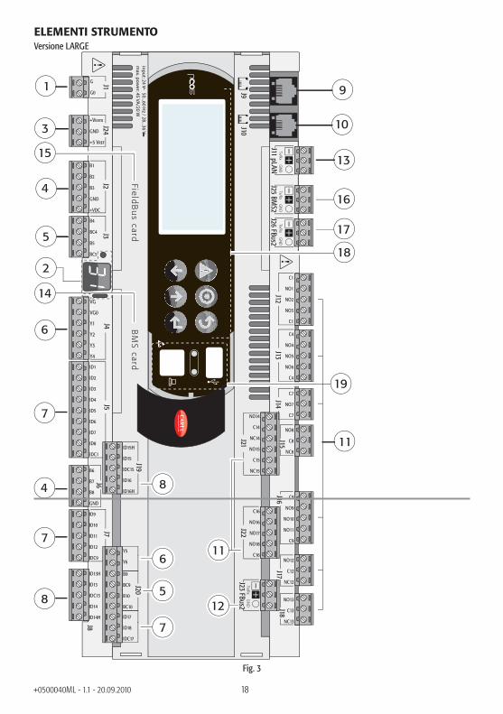
Legenda (Fig. 3-4-5)1. connettore per l’alimentazione [G (+), G0 (-)];2. tasto indirizzo pLAN, display 7 segmenti e LED (power on e
overload morsetto +Vdc);3. alimentazione aggiuntiva per terminale e sonde raziometriche
0…5 V;4. ingressi analogici universali NTC, 0…1 V, 0…5 V raziometrici,
0…10 V, 0…20 mA, 4…20 mA;5. ingressi analogici passivi NTC, PT1000, ON/OFF;6. uscite analogiche 0…10 V;7. ingressi digitali a 24 Vac/Vdc;8. ingressi digitali 230 Vac o 24 Vac/Vdc;9. connettore per il terminale sinottico (pannello esterno con
segnalazioni dirette);10. connettore per tutti i terminali standard della serie pCO e per
il download del programma applicativo;11. uscite digitali a relè;12. connettore Fieldbus2;13. connettore rete locale pLAN;14. sportello per l’inserimento dell’opzione serial card per
supervisore (BMS1);15. sportello per l’inserimento dell’opzione fi eld card (Fieldbus1);16. connettore per BMS2;17. connettore Fieldbus2;18. terminale built-in (LCD, tasti e LED);19. connettore USB Host e Slave20. Connettore Valvola ELettronica21. Ingressi analogici e digitali driver valvola22. Alimentazione esterna da modulo EVbat
20+0500040ML - 1.1 - 20.09.2010
NOTE PER L’INSTALLATORE Procedura di indirizzamento pLAN del controllo e del terminale
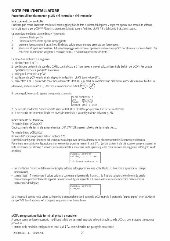
Indirizzamento del controllo L’indirizzo può essere impostato mediante il tasto raggiungibile dal foro a sinistra del display a 7 segmenti oppure con procedura software come già avviene per pCO1/XS/3. Alla prima pressione del tasto appare l’indirizzo pLAN. A 5 s dal rilascio il display si spegne.
La procedura mediante tasto e display 7 segmenti:1. premere il tasto per 3 s2. l’indirizzo memorizzato appare lampeggiante 3. premere ripetutamente il tasto fi no all’indirizzo voluto oppure tenere premuto per l’autorepeat4. attendere 10 s per memorizzare. Il display lampeggia velocemente. Spegnere e riaccendere pCO5 per attivare il nuovo indirizzo. Per
cancellare l’operazione spegnere il controllo entro 7 s dall’ultima pressione del tasto.
La procedura software è la seguente:1. disalimentare il pCO5;2. predisporre un terminale standard CAREL con indirizzo a 0 (non necessario se si utilizza il terminale Built-in del pCO5). Per questa operazione vedere il paragrafo successivo;3. collegare il terminale al pCO5;4. scollegare dal pCO5 eventuali altri dispositivi collegati in pLAN (connettore J11);5. alimentare il pCO5 premendo contemporaneamente i tasti UP + ALARM. La combinazione di tasti vale anche da terminale built in. In
alternativa, nei terminali PCOT, utilizzare la combinazione di tasti menu e .
6. dopo qualche secondo appare la seguente schermata:
PLAN ADDRESS: 0UP: INCREASEDOWN: DECREASEENTER: SAVE & EXIT
7. Se si vuole modifi care l’indirizzo basta agire sui tasti UP e DOWN e poi premere ENTER per confermare.8. è necessario ora impostare l’indirizzo pLAN del terminale e la confi gurazione della rete pLAN.
Indirizzamento del terminale Terminale di tipo pCOI/pCOTL’indirizzamento del terminale avviene tramite i DIP_SWITCH presenti sul retro del terminale stesso.
Terminale di tipo pGD0/1/2/3Il valore dell’indirizzo preimpostato in fabbrica è 32.È possibile confi gurare l’indirizzo del terminale solo dopo aver fornito alimentazione allo stesso tramite il connettore telefonico.Per entrare in modalità confi gurazione premere contemporaneamente i 3 tasti (anche da terminale già acceso), sempre presenti in tutte le versioni, per almeno 5 secondi; verrà visualizzata la maschera della fi gura seguente con il cursore lampeggiante nell’angolo in alto a sinistra:
Display addresssetting.........:nn
I/O Board address:xx
• per modifi care l’indirizzo del terminale (display address setting) premere una volta il tasto : il cursore si sposterà sul campo indirizzo (nn).• tramite i tasti selezionare il valore voluto, e confermare ripremendo il tasto . Se il valore selezionato è diverso da quello memorizzato precedentemente apparirà la maschera di fi gura seguente e il nuovo valore verrà memorizzato nella memoria permanente del display.
Display addresschanged
Se si imposta il campo nn al valore 0, il terminale comunicherà con il controllo pCO5 usando il protocollo “punto-punto” (non pLAN) e il campo “I/O Board address: xx” scompare in quanto privo di signifi cato.
pCO5: assegnazione lista terminali privati e condivisiA questo punto, se fosse necessario modifi care la lista dei terminali associata ad ogni singola scheda pCO5, si dovrà seguire la seguente procedura:• entrare nella modalità confi gurazione con i tasti come descritto nel paragrafo precedente;

21+0500040ML - 1.1 - 20.09.2010
• premere il tasto fi no a che il cursore si posiziona sul campo xx (I/O board address) ;• tramite i tasti scegliere l’indirizzo della scheda pCO5 desiderata. I valori selezionabili saranno solo quelli delle schede pCO5 effettivamente in linea. Se la rete pLAN non funziona correttamente, oppure non è presente nessuna scheda pCO5, non sarà possibile modifi care il campo che mostrerà solo “—”;• premendo ancora una volta il tasto verranno visualizzate in sequenza le maschere seguenti:
Terminal Config
Press ENTERto continue
P12:Adr Priv/SharedTrm1 02 ShTrm2 03 PrTrm3 None --OK?NO
• anche qui il tasto muove il cursore da un campo all’altro e i tasti cambiano il valore del campo corrente. Il campo P:xx mostra l’indirizzo della scheda selezionata; nell’esempio di fi gura è stata selezionata la 12;• per uscire dalla procedura di confi gurazione e memorizzare i dati selezionare il campo “OK ?” impostare Yes e confermare con il tasto .I campi della colonna “Adr” rappresentano gli indirizzi dei terminali associati alla scheda pCO5 di indirizzo 12, mentre la colonna Priv/Shared indica il tipo di terminale.Attenzione: i terminali della linea pGD non possono essere confi gurati come “Sp” (shared printer) in quanto privi dell’uscita stampante.Se il terminale rimane inattivo (nessun tasto premuto) per più di 30 secondi esce automaticamente dalla procedura di confi gurazione senza memorizzare gli eventuali cambiamenti.
FUNZIONAMENTO PORTA USBpCO5 è fornito di due differenti porte USB (host e slave), da usarsi in fase di installazione e diagnostica. Alla porta host possono essere connesse periferiche di archiviazione di massa USB (pen drive, hard disk portatili, … con assorbimento massimo di 200 mA) tramite le quali è possibile effettuare una serie di operazioni:1. upload su pCO5 di fi le presenti nella periferica rimovibile: applicativo, parametri in memoria tamponata, fi le di confi gurazione per gli
storici, Bios.2. download di fi le dal pCO5 alla periferica rimovibile: applicativo, parametri in memoria tamponata, dati storici, Bios.
Per accedere al menu che consente di gestire il contenuto della periferica rimovibile connessa alla porta host, è suffi ciente tenere premuti i tasti ALARM+ENTER per alcuni secondi, fi no alla comparsa della prima maschera di sistema del Bios. Selezionando la voce FLASH/USB MEMORY e successivamente USB PEN DRIVE, si accede al menu iniziale che permette di scegliere un’operazione di upload o di download. Mediante la scelta UPLOAD si può ulteriormente specifi care se si desidera accedere al contenuto della pen drive manualmente (navigando tra le cartelle e i fi le presenti) o in maniera automatica (avendo accesso diretto a degli opportuni fi le di confi gurazione). Inoltre, nel caso in cui la periferica connessa contenga un fi le denominato AUTORUN.TXT il cui contenuto sia conforme a specifi che richieste, a terminale comparirà automaticamente una schermata che consente l’attivazione diretta della specifi ca funzionalità cui il fi le si riferisce. Dettagli in merito alla composizione di questi fi le, possono essere reperiti consultando il manuale +030220335.La scelta DOWNLOAD consente di effettuare il download dell’applicativo, degli storici, dei parametri, del Bios. Si noti che durante le fasi di upload e download dei contenuti mediante la porta host, l’operatività del Bios di pCO5 è limitata alla sola gestione USB.
Alla porta USB slave è possibile connettere direttamente un PC, senza utilizzare strumenti aggiuntivi. Per l’utilizzo delle funzionalità è necessario utilizzare il software pCO Manager. Le operazioni consentite tramite questa porta consistono in:1. upload di fi le su pCO5,2. download sul PC di contenuti presenti sul pCO5,3. gestione della fl ash nand,4. commissioning.L’upload mediante la porta slave prevede che possa essere caricato un applicativo o un Bios. L’applicativo si intende comprensivo di eventuale fi le relativo ai parametri della memoria tamponata e di eventuali fi le di confi gurazione per la raccolta degli storici. Le operazioni di download consentite sono tutte quelle previste da pCO Manager, ovvero download degli storici e del contenuto delle memorie T e P. Mediante la connessione alla porta slave è anche possibile gestire la fl ash nand, con la possibilità di caricare/scaricare dei fi le, cancellare dei fi le o formattare completamente la memoria. Sulla stessa porta è possibile effettuare il commissioning, a patto di utilizzare un applicativo opportuno e le relative informazioni contenute nel fi le .2cf.
ATTENZIONE: Le due porte USB non possono essere utilizzate simultaneamente. È fondamentale che le due porte siano utilizzate in maniera distinta, in caso contrario non vi è garanzia dell’effettivo corretto funzionamento di pCO5.
italiano
22+0500040ML - 1.1 - 20.09.2010
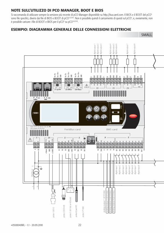
NOTE SULL’UTILIZZO DI PCO MANAGER, BOOT E BIOSSi raccomanda di utilizzare sempre la versione più recente di pCO Manager disponibile su http://ksa.carel.com. Il BIOS e il BOOT del pCO5 sono fi le specifi ci, diversi dai fi le di BIOS e BOOT di pCO1/2/3/XS. Non è possibile quindi il caricamento di questi sul pCO5, e, ovviamente, non è possibile caricare i fi le di BOOT e BIOS per il pCO5 su pCO1/2/3/XS.
ESEMPIO: DIAGRAMMA GENERALE DELLE CONNESSIONI ELETTRICHEG G0
230/
24 V
ac
M
OU
T +V
anal
og o
utpu
t 1 (0
/10
Vdc)
anal
og o
utpu
t 2 (0
/10
Vdc)
anal
og o
utpu
t 3 (0
/10
Vdc)
anal
og o
utpu
t 4 (0
/10
Vdc)
L N
digi
tal o
utpu
t 1di
gita
l out
put 2
digi
tal o
utpu
t 3
digi
tal o
utpu
t 4
digi
tal in
put 1
digi
tal in
put 2
digi
tal in
put 3
digi
tal in
put 4
digi
tal in
put 5
digi
tal in
put 6
digi
tal in
put 7
digi
tal in
put 8
digi
tal o
utpu
t 5di
gita
l out
put 6
digi
tal o
utpu
t 7
digi
tal o
utpu
t 8
prob
e 1 (0
/5 V
)
prob
e 2 (4
/20 m
A)
prob
e 3 (0
/1 Vd
c or 4
/20 m
A)
prob
e 4 C
arel
NTC
prob
e 5 PT
1000
Rx-/
Tx-
Rx+
/Tx+
GND
C1 NO1
NO2
NO3
C1 C4 NO4
NO5
NO6
C4 C7 NO7
C7 NO8
C8 NC8
G G0 B1 B2 B3
GND
+VD
C
+Vt
erm
GND
+5
VREF B4 BC
4 B5 BC5 VG VG0 Y1 Y2 Y3 Y4 ID1
ID2
ID3
ID4
ID5
ID6
ID7
ID8
IDC1
SMALL
C1
NO1
NO2
NO3 C1 C4
NO4
NO5
NO6 C4 C7
NO7 C7
NO8 C8
NC8
G G0 B1 B2 B3 GND
+VD
C
+Vt
erm
GND
+5
VREF
B4 BC4
B5 BC5
VG VG0
Y1 Y2 Y3 Y4 ID1
ID2
ID3
ID4
ID5
ID6
ID7
ID8
IDC1
B6 B7 B8 GND
J1 J24 J2 J3 J4 J5
J14J11 pLAN
J10J9
J13J12 J16J15
J6
Fie ldBus card BMS card
J25 BMS2 J26 FBus2
input: 24 V 50...60 Hz / 28...36 Vmax. power: 45 VA/20 W
Rx-/
Tx-
Rx+
/Tx+
GND
Rx-/
Tx-
Rx+
/Tx+
GND

anal
og o
utpu
t 5 (0
/10
Vdc)
digi
tal in
put 1
5
digi
tal in
put 1
6
digi
tal in
put 1
7
digi
tal in
put 1
8
digi
tal o
utpu
t 14
digi
tal o
utpu
t 15
digi
tal o
utpu
t 16
digi
tal o
utpu
t 17
digi
tal o
utpu
t 18
prob
e 9 C
AREL
NTC
prob
e 10
volta
ge-fr
eedi
gita
l inpu
t
anal
og o
utpu
t 6 (0
/10
Vdc)
out H M
NTC
NTC
+ (G
)di
gita
l inpu
t 9
CP digi
tal in
put 1
0di
gita
l inpu
t 11
digi
tal in
put 1
2
digi
tal in
put 1
3
digi
tal in
put 1
4
digi
tal o
utpu
t 9
digi
tal o
utpu
t 10
digi
tal o
utpu
t 11
digi
tal o
utpu
t 12
digi
tal o
utpu
t 13
prob
e 8 C
AREL
NTC
prob
e 6 -
7N
O12
C12
NC1
2
NO1
3
C13
NC1
3
C9 NO9
NO1
0
NO1
1
C9
B6 B7 B8
GND
ID9
ID10
ID11
ID12
IDC9
ID13
H
ID13
IDC1
3
ID14
ID14
H
MEDIUM LARGE
J20
J21 J22
J19
NO1
4
C14
NC1
4
NO1
5
C15
NC1
5
C16
NO1
6
NO1
7
NO1
8
C16
ID15
H
ID15
IDC1
5
ID16
ID16
H
Y5 Y6 ID17
ID18
IDC1
7
B9 BC9
B10
BC10
J23 FBus2
NO1
2
C12
NC1
2
NO1
3
C13
NC1
3C9
NO9
NO1
0
NO1
1 C9
B6 B7 B8 GND
ID9
ID10
ID11
ID12
IDC9
ID13
H
ID13
IDC1
3
ID14
ID14
H
J7
J8
J16 J17 J18
J6
Rx-/
Tx-
Rx+
/Tx+
GND

24+0500040ML - 1.1 - 20.09.2010
AVVERTENZE IMPORTANTIIl prodotto CAREL è un prodotto avanzato, il cui funzionamento è specifi cato nella documentazione tecnica fornita col prodotto o scaricabile, anche anteriormente all’acquisto, dal sito internet www.carel.com. Il cliente (costruttore, progettista o installatore dell’equipaggiamento fi nale) si assume ogni responsabilità e rischio in relazione alla fase di confi gurazione del prodotto per il raggiungimento dei risultati previsti in relazione all’installazione e/o equipaggiamento fi nale specifi co.La mancanza di tale fase di studio, la quale è richiesta/indicata nel manuale d’uso, può generare malfunzionamenti nei prodotti fi nali di cui CAREL non potrà essere ritenuta responsabile.Il cliente fi nale deve usare il prodotto solo nelle modalità descritte nella documentazione relativa al prodotto stesso.La responsabilità di CAREL in relazione al proprio prodotto è regolata dalle condizioni generali di contratto CAREL editate nel sito www.carel.com e/o da specifi ci accordi con i clienti.

25+0500040ML - 1.1 - 20.09.2010

26+0500040ML - 1.1 - 20.09.2010

Indice / Contents / Inhalt / Sommaire
Foglio istruzioni 3
Technical leafl et 27


5+0500040ML - 1.1 - 20.09.2010
TECHNICAL SPECIFICATIONSpCO5 is a microprocessor electronic controller compatible as concerns both hardware and software with the pCO3 family. Developed by CAREL in compliance with the European RoHS directives, these controllers can be used for multiple applications in the air-conditioning and refrigeration sectors. They ensure maximum versatility of application, allowing specifi c products to be developed to customer requirements.pCO5 runs the control program, and comes with a set of terminals for connecting the various devices (compressors, fans,...). The program and the parameters are saved to FLASH-MEMORY and E2PROM, meaning all data is retained even in the event of power failures (without requiring a backup battery).
pCO5 can connect to a pLAN (pCO Local Area Network) and, in addition to other pCO5 devices, can also be connected to all other pCO sistema controllers and all pGD family terminals. Each controller in the pLAN network can exchange any variable, either digital or analogue, depending on the application program used. Up to 32 units can be connected (pCO controllers or terminals), for effective sharing of information.pCO5 comes with two additional RS485 built-in serial ports compared to the other pCO controllers, one FieldBus and the other supervisor/telemaintenance (BMS). The BMS serial line is connected, using the CAREL or Modbus® communication protocol over RS485, by fi tting the pCO5 with an optional serial card or alternatively using the built-in serial port.Other optional cards can be used to connect a supervisor over standards other than RS485. Finally, the FieldBus serial connection, using the optional or built-in card, provides connection to controlled fi eld devices (for example: valves, pCOe I/O expansions, electronic valve external drivers,...). The pCO5 Medium size also features an optional new integrated solution: version with built-in EVD EVO valve driver, single or twin.
Versions available: • SMALL, MEDIUM, LARGE, EXTRALARGE (digital output with normally open contacts), valve driver;• with or without Built-In terminal;• with additional NAND FLASH memory;• with or without solid state relay (SSR) digital outputs 24Vac/Vdc or 110/230 Vac/Vdc;• with or without USB Master and Slave.
Uploading the application programThe application program can be loaded onto the fl ash memory in different ways:1. by key:
• smart key code PCOS00AKY0;• USB pen drive;
2. by PC:• 485 serial port (28.8 kbps and 115.2 kbps) using USB-485 adapter code “CVSTDUTLF0”• USB slave
To upload via PC the “pCO Manager” program is required, available free-of-charge at the ksa.carel.com website.
Power supplyA class 2 safety transformer with a minimum rating of 50 VA (100 VA on the versions with built-in valve driver) and a 2.5 AT fuse must be used in the installation to supply just one pCO5 controller. The power supply to the pCO5 controller and terminal (or pCO5 controllers and terminals) should be separated from the power supply to the other electrical devices (contactors and other electromechanical components) inside the electrical panel. If the secondary of the transformer is earthed, make sure that the earth wire is connected to terminal G0. This is true for all the devices connected to the pCO5. If more than one pCO5 is connected, make sure that the G and G0 references are observed (G0 must be maintained for all boards).If using the pLAN network and for further details, see the CAREL pCO sistema manual code +030220335.
FieldBus options BMS options
opto-isol. 485 PCO100FD10 hydronic CAN PCOS00HBB0tLAN PCO100TLN0 485/Modbus® PCOS004850Belimo MP-BUS PCO100MPB0 modem PCO100MDM0modem PCOS00FD20 Ethernet/BACnet board PCO1000WB0hydronic CAN PCOS00HBF0 BACnet MS/TP board PCO1000BA0Konnex PCOS00KXF0 Konnex PCOS00KXB0
LonWorks FTT10 PCO10000F0LonWorks FTT10 standard chiller profile PCO10001F0
English

6+0500040ML - 1.1 - 20.09.2010
ConnectorsExample of connector codes: PCO5CON***, see the following table for the description:
PCO5CON * * 00= screw1= spring loaded
S= smallM= mediumL= largeZ= extra large 2= medium with valve driver
DisplayBuilt-in PGD1 (132x64 pixels), with backlit keypad.
TECHNICAL SPECIFICATIONS
Physical specifi cationsdimensions SMALL version installable on 13 DIN modules, 110 x 227.5 x 60 mm
MEDIUM, LARGE, EXTRALARGE and VALVE DRIVER versions installable on 18 DIN modules, 110 x 315 x 60 mmassembly DIN rail
Plastic case• fi tted on DIN rail as per DIN 43880 and IEC EN 50022;• material: technopolymer;• fl ame retardance: V2 (to UL94) and 850 °C (IEC 60695);• ball pressure test: 125 °C;• resistance to creeping current: 250 V;• colour: grey RAL 7035;
Electrical specifi cationspower supply (controller with terminal connected) Versions without built-in valve driver:
24 Vac +10/-15% 50 to 60 Hz and 28 to 36 Vdc +10/-20%; maximum current 45 VA/20 WVersions with built-in valve driver:24 Vac +10/-15% 50 to 60 Hz;maximum current: 80 VA/35 W
terminal block with male/female plug-in connectors, max voltage 250 Vac;cable cross-sect: min. 0.5 mm2 - max 2.5 mm2
CPU H8SX1651, 32 bit, 44 MHzmemory (FLASH MEMORY) 2+2 MB. Further 32 MB NAND Flash memory also available.data memory (static RAM) 512 kB at 16 bit s(296 kB Bios; 216 kB application)parameter data memory 13 kB at 16 bit (max limit: 100,000 writes per memory location) plus 32 kB E2PROM (not
available in pLAN)working cycle time (applications of avg. complexity) 0.2 s (typical)clock with battery standardclock precision 100 ppmbattery specifi cations Lithium button battery, code CR2430, voltage 3 Vdc (dimensions 24x3 mm)
Digital inputs type ID1 to ID18 optically-isolated (voltage contact), B4, B5, B9, B10 non optically-isolated (free
contact)maximum number voltage inputs optically-isolated 8: SMALL; 14: MEDIUM & EXTRALARGE ; 18: LARGE. As per combinations shown below:
no. 24 Vac opto inputs50/60 Hz o 24 Vdc
no. 24 Vac/Vdc or 230 Vac opto inputs (50/60 Hz)
total inputs
SMALL 8 none 8MEDIUM/EXTRALARGE
12 2 14
LARGE 14 4 18maximum number inputs free contact not optically-isolated
2: SMALL, MEDIUM & EXTRALARGE (B4 and B5); 4: LARGE (B4, B5, B9, B10)
Classifi cation of measurement circuits (IEC EN 61010-1)
Category 1 (J5, J7, J20) 24 Vac/Vdc - Category 3 (J8, J19) 230 Vac

7+0500040ML - 1.1 - 20.09.2010
Voltage-free digital input current (B4, B5, B9, B10) 5 mADigital input current with 24 Vac voltage signal 5 mADigital input current with 230 Vac voltage signal 5 mA
WARNINGS: - IDH digital inputs 230 Vac 50/60 Hz (10/-15%) protected by a single 500 mAT fuse; - the two 230/24 Vac inputs at J8 and J12 have the same common and so both will be either 24 Vac/Vdc or 230 Vac. There is double insulation between the two inputs and the rest of the controller; - the external contact connected to the digital inputs must have a minimum current of 5 mA; - for DC digital inputs (Vdc), either the + or the – can be connected to the common (IDC1).Note: separate as much as possible the probe signal and digital input cables from the cables to inductive loads and power cables, to avoid possible electromagnetic disturbance.
Fast digital input specifi cations (B4 and B5)When confi gured as fast digital inputs, B4 and B5 can measure a signal with a maximum frequency of 2 KHz and a resolution of ±1 Hz. This is possible as the BIOS provides the application program two pairs of variables that count the zero crossing of the input signal and the corresponding frequency in Hz.
Analogue inputs analogue conversion 10-bit A/D converter embedded in CPUtype universal: (inputs B1, B2, B3, B6, B7, B8) CAREL NTC temperature sensor (-50T90 °C; R/T 10 k at 25 °C),
NTC HT 0T150 °C, voltage: 0 to 1 Vdc, 0 to 5 V ratiometric or 0 to 10 Vdc, current: 0 to 20 mA or 4 to 20 mA, selectable via software. Input resistance for 0 to 20 mA= 100passive: (inputs B4, B5, B9, B10) CAREL NTC temp. sensor (see universal), PT1000 (-100T200 °C; R/T 1000 at 0°C) or volt.-free digital input (5 mA), selected via software;
maximum number 5: SMALL; 8: MEDIUM & EXTRALARGE; 10: LARGEtime constant for each input 0,5 sprecision ± 0.3 % of full scaleclass. of measurement circuits (IEC EN 61010-1)
Category 1
input impedance NTC 10 k4-20 mA 100 0-1 V 100 k0-5 V 20 k0-10 V 12,7 kPT1000 10 k
WARNING: the 21 Vdc available at terminal +Vdc (J2) can be used to power any active probes; the maximum current is 150 mA, protected against short-circuits. To power the 0 to 5 Vdc ratiometric probes, use the +5VREF (Imax: 60 mA) available at terminal J24. Only use these voltages to power the active probes connected to pCO5.
Analogue outputs type 0 to 10 Vdc optically-isolated on Y1, Y2, Y3, Y4, Y5 and Y6 / phase control on Y3 and Y4maximum number 4: SMALL, MEDIUM & EXTRALARGE ; 6: LARGEpower supply 24 Vac/Vdc external on VG(+), VG0(-)resolution 8 bitmaximum load 1.5 k (7 mA)precision ± 2 % of full scale on outputs: Y1, Y2, Y3, Y4, Y5 and Y6
WARNINGS: • A 0 to 10 Vdc analogue output can be connected in parallel to other outputs of the same type, or alternatively to an external source
of voltage. The higher voltage will be considered. Correct operation is not guaranteed if actuators with voltage inputs are connected. Power the VG-VG0 analogue outputs at the same voltage on G-G0: Connect G0 to VG0 and G to VG. This is valid for both alternating and direct current power supplies.
• For phase control outputs (PWM), note that synchronicity (zero crossing) is taken from G/G0 and only with 24 Vac power supply (not Vdc.
Digital outputs type relaysmax. number 8: SMALL; 13: MEDIUM; 18: LARGE; 29: EXTRALARGE
For the connections see Figs. 3 and 4 (reference NO*, NC* and C*). Note that outputs with changeover contacts are kept separate (i.e. without poles
English
8+0500040ML - 1.1 - 20.09.2010
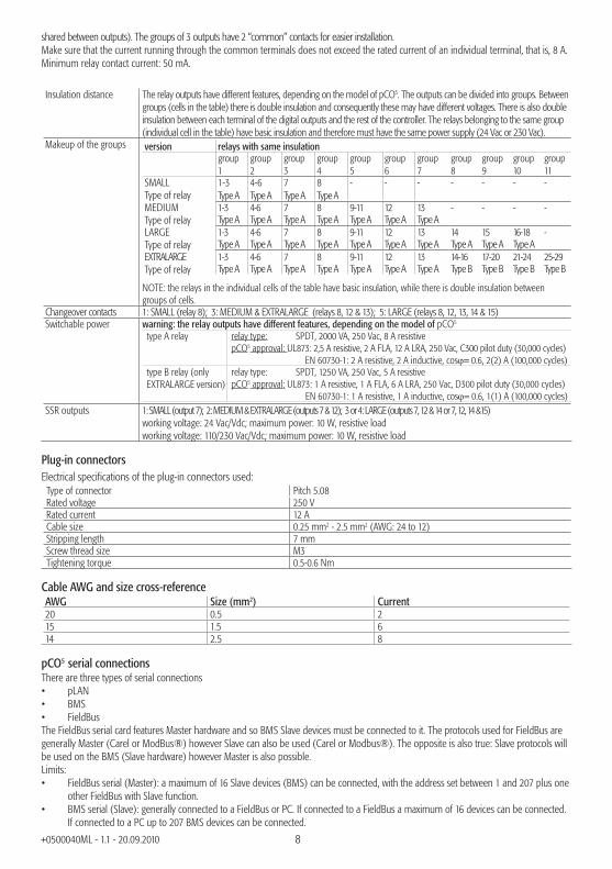
shared between outputs). The groups of 3 outputs have 2 “common” contacts for easier installation.Make sure that the current running through the common terminals does not exceed the rated current of an individual terminal, that is, 8 A. Minimum relay contact current: 50 mA.
Insulation distance The relay outputs have different features, depending on the model of pCO5. The outputs can be divided into groups. Between groups (cells in the table) there is double insulation and consequently these may have different voltages. There is also double insulation between each terminal of the digital outputs and the rest of the controller. The relays belonging to the same group (individual cell in the table) have basic insulation and therefore must have the same power supply (24 Vac or 230 Vac).
Makeup of the groups version relays with same insulationgroup 1
group 2
group 3
group 4
group 5
group 6
group 7
group 8
group 9
group 10
group 11
SMALLType of relay
1-3 4-6 7 8 - - - - - - -Type A Type A Type A Type A
MEDIUMType of relay
1-3 4-6 7 8 9-11 12 13 - - - -Type A Type A Type A Type A Type A Type A Type A
LARGEType of relay
1-3 4-6 7 8 9-11 12 13 14 15 16-18 -Type A Type A Type A Type A Type A Type A Type A Type A Type A Type A
EXTRALARGE Type of relay
1-3 4-6 7 8 9-11 12 13 14-16 17-20 21-24 25-29Type A Type A Type A Type A Type A Type A Type A Type B Type B Type B Type B
NOTE: the relays in the individual cells of the table have basic insulation, while there is double insulation between groups of cells.
Changeover contacts 1: SMALL (relay 8); 3: MEDIUM & EXTRALARGE (relays 8, 12 & 13); 5: LARGE (relays 8, 12, 13, 14 & 15)Switchable power warning: the relay outputs have different features, depending on the model of pCO5
type A relay relay type: SPDT, 2000 VA, 250 Vac, 8 A resistivepCO5 approval: UL873: 2,5 A resistive, 2 A FLA, 12 A LRA, 250 Vac, C300 pilot duty (30,000 cycles) EN 60730-1: 2 A resistive, 2 A inductive, cos= 0.6, 2(2) A (100,000 cycles)
type B relay (only EXTRALARGE version)
relay type: SPDT, 1250 VA, 250 Vac, 5 A resistive pCO5 approval: UL873: 1 A resistive, 1 A FLA, 6 A LRA, 250 Vac, D300 pilot duty (30,000 cycles) EN 60730-1: 1 A resistive, 1 A inductive, cos= 0.6, 1(1) A (100,000 cycles)
SSR outputs 1: SMALL (output 7); 2: MEDIUM & EXTRALARGE (outputs 7 & 12); 3 or 4: LARGE (outputs 7, 12 & 14 or 7, 12, 14 &15)working voltage: 24 Vac/Vdc; maximum power: 10 W, resistive loadworking voltage: 110/230 Vac/Vdc; maximum power: 10 W, resistive load
Plug-in connectorsElectrical specifi cations of the plug-in connectors used:
Type of connector Pitch 5.08Rated voltage 250 VRated current 12 ACable size 0.25 mm2 - 2.5 mm2 (AWG: 24 to 12)Stripping length 7 mmScrew thread size M3Tightening torque 0.5-0.6 Nm
Cable AWG and size cross-referenceAWG Size (mm2) Current20 0.5 215 1.5 614 2.5 8
pCO5 serial connectionsThere are three types of serial connections• pLAN• BMS• FieldBusThe FieldBus serial card features Master hardware and so BMS Slave devices must be connected to it. The protocols used for FieldBus are generally Master (Carel or ModBus®) however Slave can also be used (Carel or Modbus®). The opposite is also true: Slave protocols will be used on the BMS (Slave hardware) however Master is also possible.Limits:• FieldBus serial (Master): a maximum of 16 Slave devices (BMS) can be connected, with the address set between 1 and 207 plus one
other FieldBus with Slave function.• BMS serial (Slave): generally connected to a FieldBus or PC. If connected to a FieldBus a maximum of 16 devices can be connected.
If connected to a PC up to 207 BMS devices can be connected.

9+0500040ML - 1.1 - 20.09.2010
• pLAN (Multi Master): maximum 32 devices.Serial ZERO: PLAN - J10, J11 • Integrated on main board• Not optically-isolated• HW driver: RS485• Connectors: Telephone jack + 3-pin plug-in p. 5.08
Serial ONE: BMS 1 Serial Card • Not integrated on main board• HW driver: not present• Can be used with all pCO family optional BMS cards
Serial TWO: FieldBus 1 • Not integrated on main board• HW driver: not present• Can be used with all pCO family optional FieldBus cards
Serial THREE: BMS 2 - J25 • Integrated on main board• Not optically-isolated (Optically-isolated version also available)• HW driver: RS485 • 3-pin plug-in connector p. 5.08
Serial FOUR: FieldBus 2 - J26 (and J23 on Large and ExtraLarge version) • Integrated on main board• Not optically-isolated• HW driver: RS485• 3-pin plug-in connector p. 5.08• J23 and J26 are electrically insulated but both managed by the same serial port (FOUR).
pLAN network/user terminal connectiontype asynchronous half duplex RS485transmission speed 62.5 Kbps or 115.2 Kbps selectable via softwarePGD0, PGD1 terminal connector 6-pin telephone (J10)pLAN network/other terminals 3-pin plug-in connector (J11)maximum number of units connectable 32
The maximum distance between the pCO and the user terminal is shown in the following table.type of cable power supply distance power supplytelephone 10 m taken from pCO (150 mA)AWG24 shielded cable 200 m taken from pCO (150 mA)AWG20/22 shielded cable 500 m separate power supply via TCONN6J000
The maximum distance between two pCO5 devices with AWG20/22 shielded cable is 500 m.
Note:• J10 can only be connected to one terminal (pCOT, pCOI, pGD0, pGD1) or two terminals when the backlighting for the display is not activated. • Except PGD0 and PGD1 terminals, the other terminals should be always powered with separate power supplies.• The 21 Vdc available at +Vterm (J24) can be used to power an external terminal as an alternative to the one connected to terminal J10, with maximum current 1.5 W.
English

10+0500040ML - 1.1 - 20.09.2010
VERSION WITH ELECTRONIC EXPANSION VALVE DRIVERThe pCO5 Medium size features an optional new integrated solution: the version with built-in EVD EVO driver, single or twin. The driver card is housed on the pCO5 in the socket provided for the inputs / outputs on the Large size board, hence the reason it’s only available on the pCO5 Medium (not Small, Large, nor ExtraLarge) and doesn’t require an external power supply..
The built-in driver replicates all the hardware and functions logical of the “EVD Evolution TWIN” driver, i.e. independently controls one or two electronic expansion valves with two-pole stepper motors. The only difference between the two versions is the absence of the relay output. For details on the valve control logic, setup and installation see the EVD EVO manual (code + 0300005EN).
In the same way as EVD EVO, on the pCO5 the integrated driver is available in the CAREL and Universal versions. The “Universal” models are used to control both CAREL electronic expansion valves and products made by other manufacturers (see the table below), while the CAREL models only manage CAREL valves.
Valve compatibility tableManufacturer Compatible modelsCAREL E*V****ALCO EX4; EX5; EX6; EX7; EX8 330 Hz (rec’d by CAREL); EX8 500 Hz (to ALCO specs)SPORLAN SEI 0.5-11; SER 1.5-20; SEI 30; SEI 50; SEH 100; SEH175Danfoss ETS 12.5-25B; ETS 50B; ETS 100B; ETS 250; ETS 400CAREL Two CAREL EXVs connected together SPORLAN SER(I) G, J, K
Serial communication and programming
Communication between the pCO5 and its built-in EVD EVO driver is managed internally using the Fieldbus2 serial port. The FieldBus2 serial port (J26) is however electrically insulated from the driver serial line: this ensures that in the event of external faults on the line connected to FBus2, the internal driver can continue working independently and correctly.The driver can only be confi gured exclusively using the pCO5 application developed in 1Tool, no external displays are available for the EVD EVO.
The 1tool development environment features a module for managing the EVD EVO: the same module can be used to manage the internal driver, as if it were managing an external EVD EVO connected to the FBus2 port.
pCO5 Medium manages the integrated driver board as an EVD EVO Twin external connected to Field Bus 2. At a 1Tool application program level, the valve driver must be connected to FBus2. Consequently, any other devices physically connected to the Fbus port (J26) must have the same communication protocol (CAREL Standard Master or Modbus® Master), the same baud-rate, stop bits and parity.
It must also be remembered that the address of the internal driver is 198 (default for EVD EVO), so any other devices connected to J26 must have an address other than 198. External EVD EVO drivers can be connected to FieldBus 1 (optional card) without limits.
11+0500040ML - 1.1 - 20.09.2010
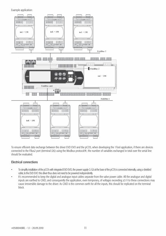
Example application:
To ensure effi cient data exchange between the driver EVD EVO and the pCO5, when developing the 1Tool application, if there are devices connected to the FBus2 port (terminal J26) using the Modbus protocol®, the number of variables exchanged in total over the serial line should be evaluated.
Electrical connections
• To simplify installation of the pCO5 with integrated EVD EVO, the power supply G-G0 at the base of the pCO5 is connected internally, using a shielded cable, to the EVD EVO: the driver thus does not need to be powered independently.
• It’s recommended to keep the digital and analogue input cables separate from the valve power cable. All the analogue and digital inputs are earthed to GND, and consequently the application, even temporary, of voltages exceeding ±5 V to these connections may cause irreversible damage to the driver. As GND is the common earth for all the inputs, this should be replicated on the terminal block.
12+0500040ML - 1.1 - 20.09.2010
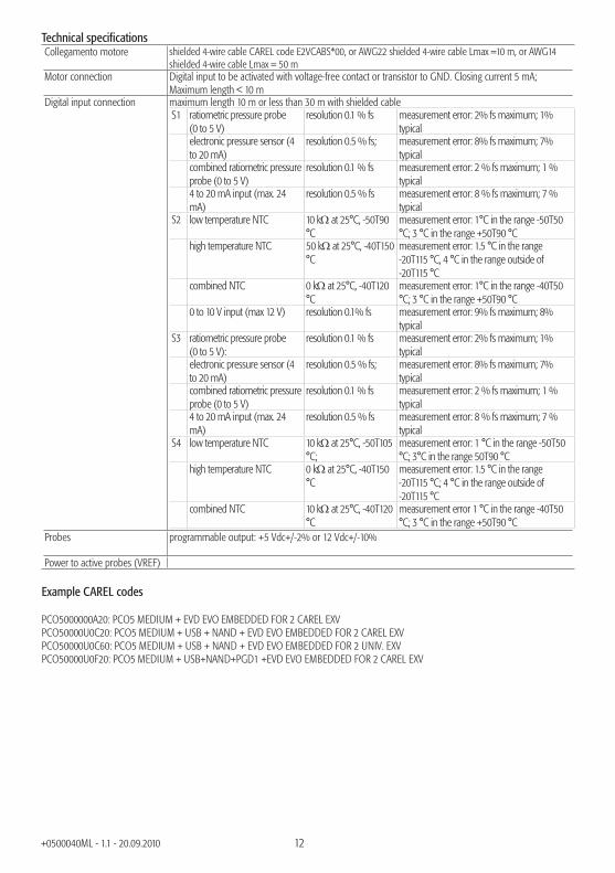
Technical specifi cationsCollegamento motore shielded 4-wire cable CAREL code E2VCABS*00, or AWG22 shielded 4-wire cable Lmax =10 m, or AWG14
shielded 4-wire cable Lmax = 50 mMotor connection Digital input to be activated with voltage-free contact or transistor to GND. Closing current 5 mA;
Maximum length < 10 mDigital input connection maximum length 10 m or less than 30 m with shielded cable
S1 ratiometric pressure probe (0 to 5 V)
resolution 0.1 % fs measurement error: 2% fs maximum; 1% typical
electronic pressure sensor (4 to 20 mA)
resolution 0.5 % fs; measurement error: 8% fs maximum; 7% typical
combined ratiometric pressure probe (0 to 5 V)
resolution 0.1 % fs measurement error: 2 % fs maximum; 1 % typical
4 to 20 mA input (max. 24 mA)
resolution 0.5 % fs measurement error: 8 % fs maximum; 7 % typical
S2 low temperature NTC 10 k at 25°C, -50T90 °C
measurement error: 1°C in the range -50T50 °C; 3 °C in the range +50T90 °C
high temperature NTC 50 k at 25°C, -40T150 °C
measurement error: 1.5 °C in the range -20T115 °C, 4 °C in the range outside of -20T115 °C
combined NTC 0 k at 25°C, -40T120 °C
measurement error: 1°C in the range -40T50 °C; 3 °C in the range +50T90 °C
0 to 10 V input (max 12 V) resolution 0.1% fs measurement error: 9% fs maximum; 8% typical
S3 ratiometric pressure probe (0 to 5 V):
resolution 0.1 % fs measurement error: 2% fs maximum; 1% typical
electronic pressure sensor (4 to 20 mA)
resolution 0.5 % fs; measurement error: 8% fs maximum; 7% typical
combined ratiometric pressure probe (0 to 5 V)
resolution 0.1 % fs measurement error: 2 % fs maximum; 1 % typical
4 to 20 mA input (max. 24 mA)
resolution 0.5 % fs measurement error: 8 % fs maximum; 7 % typical
S4 low temperature NTC 10 k at 25°C, -50T105 °C;
measurement error: 1 °C in the range -50T50 °C; 3°C in the range 50T90 °C
high temperature NTC 0 k at 25°C, -40T150 °C
measurement error: 1.5 °C in the range -20T115 °C; 4 °C in the range outside of -20T115 °C
combined NTC 10 k at 25°C, -40T120 °C
measurement error 1 °C in the range -40T50 °C; 3 °C in the range +50T90 °C
Probes programmable output: +5 Vdc+/-2% or 12 Vdc+/-10%
Power to active probes (VREF)
Example CAREL codes
PCO5000000A20: PCO5 MEDIUM + EVD EVO EMBEDDED FOR 2 CAREL EXVPCO50000U0C20: PCO5 MEDIUM + USB + NAND + EVD EVO EMBEDDED FOR 2 CAREL EXVPCO50000U0C60: PCO5 MEDIUM + USB + NAND + EVD EVO EMBEDDED FOR 2 UNIV. EXVPCO50000U0F20: PCO5 MEDIUM + USB+NAND+PGD1 +EVD EVO EMBEDDED FOR 2 CAREL EXV
13+0500040ML - 1.1 - 20.09.2010
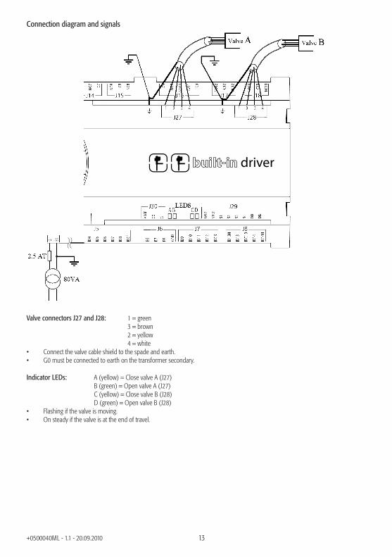
Connection diagram and signals
driver
Valve connectors J27 and J28: 1 = green 3 = brown 2 = yellow 4 = white• Connect the valve cable shield to the spade and earth.• G0 must be connected to earth on the transformer secondary.
Indicator LEDs: A (yellow) = Close valve A (J27) B (green) = Open valve A (J27) C (yellow) = Close valve B (J28) D (green) = Open valve B (J28)• Flashing if the valve is moving.• On steady if the valve is at the end of travel.

14+0500040ML - 1.1 - 20.09.2010
Connections based on the type of valves
driver
G G0

15+0500040ML - 1.1 - 20.09.2010
Other specifi cationsstorage conditions -40T70 °C, 90% rH non-condensingoperating conditions -25T60 °C, 90% rH non-condensingindex of protection IP20, IP40 on the front panel onlyenvironmental pollution 2class according to protection against electric shock to be integrated into Class 1 and/or 2 appliances in the versions without
valve driver, Class 1 in versions with valve driver.PTI of the insulating materials PCB: PTI250; insulation material: PTI 175period of stress across the insulating parts longtype of action 1C; 1Y for SSR versionstype of disconnection or microswitching microswitchingcategory of resistance to heat and fi re category D (UL94 - V2)immunity against voltage surges category 2ageing characteristics (operating hours) 80,000no. of automatic operating cycles 100,000 (EN 60730-1); 30,000 (UL 873)software class and structure Class Acategory of immunity to voltage surges (IEC EN 61000-4-5) Category 3The device is not designed to be hand-held when powered.
Product certifi cationsElectrical safety EN 60730-1, EN 60730-2Electromagnetic compatibility Versions without valve driver: EN 61000-6-1, EN 61000-6-2, EN 61000-6-
2/EC, EN 61000-6-2/IS1, EN 61000-6-3, EN 61000-6-4; EN 55014-1, EN 55014-2, EN 55014-2/EC, EN 55014-2/A1, EN 55014-2/IS1, EN 55014-2/A2Versions with valve driver: EN 61000-6-1, EN 61000-6-2, EN 61000-6-2/EC, EN 61000-6-2/IS1, EN61000-6-3, EN 61000-6-4
WARNINGS• for applications subject to considerable vibrations (1.5 mm pk-pk 10/55 Hz), secure the cables connected to the pCO5 around 3 cm from
the connectors using clamps;• cables longer then 10 m, excepted the cables for relays and 230 Vac digital inputs, must be shielded with shield connected to the
ground; • in residential environments (EN55014), in the versions without valve driver the connection cable between the pCO5, the terminal and
the other serial boards must be shielded and earthed at both ends;• the device must be installed according to the standards and legislation in force in the country where it is used;• for safety reasons the equipment must be housed inside an electrical panel, so that the only accessible part is the display and the
keypad;• all the extra low voltage connections (analogue and 24 Vac/Vdc digital inputs, analogue outputs, serial bus connections, power supplies)
must have reinforced or double insulation from the mains network;• in the event of malfunctions, do not attempt to repair the device, but rather contact the CAREL service centre;• make sure that the temperature inside the panel where the pCO5 is installed does not exceed the operating conditions
ACCESSORIESPCOS00AKY0 pCO Sistema smart key0907877AXX external ferrite for pCO5 power cableS90CONN002 pGD terminal connection cable L= 0.8 mS90CONN000 pGD terminal connection cable L= 1.5 mS90CONN001 pGD terminal connection cable L= 3 m
16+0500040ML - 1.1 - 20.09.2010
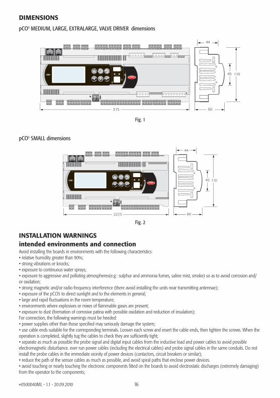
DIMENSIONS
pCO5 MEDIUM, LARGE, EXTRALARGE, VALVE DRIVER dimensions
11045
315 60
44
Fig. 1
pCO5 SMALL dimensions
227,5
11045
60
44
Fig. 2
INSTALLATION WARNINGSintended environments and connectionAvoid installing the boards in environments with the following characteristics:• relative humidity greater than 90%;• strong vibrations or knocks;• exposure to continuous water sprays;• exposure to aggressive and polluting atmospheres(e.g.: sulphur and ammonia fumes, saline mist, smoke) so as to avoid corrosion and/or oxidation;• strong magnetic and/or radio frequency interference (there avoid installing the units near transmitting antennae);• exposure of the pCO5 to direct sunlight and to the elements in general;• large and rapid fl uctuations in the room temperature;• environments where explosives or mixes of fl ammable gases are present;• exposure to dust (formation of corrosive patina with possible oxidation and reduction of insulation);For connection, the following warnings must be heeded:• power supplies other than those specifi ed may seriously damage the system;• use cable ends suitable for the corresponding terminals. Loosen each screw and insert the cable ends, then tighten the screws. When the operation is completed, slightly tug the cables to check they are suffi ciently tight;• separate as much as possible the probe signal and digital input cables from the inductive load and power cables to avoid possible electromagnetic disturbance. ever run power cables (including the electrical cables) and probe signal cables in the same conduits. Do not install the probe cables in the immediate vicinity of power devices (contactors, circuit breakers or similar);• reduce the path of the sensor cables as much as possible, and avoid spiral paths that enclose power devices.• avoid touching or nearly touching the electronic components fi tted on the boards to avoid electrostatic discharges (extremely damaging) from the operator to the components;

17+0500040ML - 1.1 - 20.09.2010
• separate the power supply to the digital outputs from the pCO5 power supply;• disconnect the controller from the power supply before performing any maintenance or assembly operations;• if the device is used in a manner not specifi ed by the manufacturer, the rated protection of the device may be compromised.
pCO5 does not provide protection against short-circuits and overloads, consequently suitable protection devices (2.5 AT fuses) must be installed on the power supply lines and on the 230 Vac digital input lines (500 mAT fuse)
pCO5 is not a device that guarantees electrical safety, but rather suitable operation: to prevent short-circuits from causing fi re in the electrical panels, the customer must install appropriate electromechanical protection devices on the lines in question (fuses or the like).In addition, the type of software does not guarantee electrical safety.
NO POWER & SIGNAL CABLES
TOGETHER
READ CAREFULLY IN THE TEXT!
WARNING: separate as much as possible the probe and digital input signal cables from the cables carrying inductive loads and power cables to avoid possible electromagnetic disturbance. Never run power cables (including the electrical panel wiring) and signal cables in the same conduits.
1
34
2
GUIDELINES FOR DISPOSAL• Do not dispose of the product as municipal waste; it must be disposed of through specialist waste disposal centres.
• The product contains a battery that must be removed and separated from the rest of the product according to the instructions provided, before disposing of the product.
• Improper use or incorrect disposal of the product may negative effects on human health and on the environment.• The public or private waste collection systems defi ned by local legislation must be used for disposal.• In the event of illegal disposal of electrical and electronic waste, the penalties are specifi ed by local waste disposal legislation.
5
6
English

18+0500040ML - 1.1 - 20.09.2010
PARTS OF THE INSTRUMENTLARGE version
C1
NO1
NO2
NO3
C1
C4
NO4
NO5
NO6
C4
C7
NO7
C7
NO8
C8
NC8
NO12
C12
NC12
NO13
C13
NC13
C9
NO9
NO10
NO11
C9
G
G0
B1
B2
B3
GND
+VDC
+Vterm
GND
+5 VREF
B4
BC4
B5
BC5
VG
VG0
Y1
Y2
Y3
Y4
ID1
ID2
ID3
ID4
ID5
ID6
ID7
ID8
IDC1
B6
B7
B8
GND
ID9
ID10
ID11
ID12
IDC9
ID13H
ID13
IDC13
ID14
ID14H
J1
10
1
11
J24J2
J3J4
J5J7
J8
J20
J21
J14J11 pLAN
J10J9
J13J12
J22
J16J17
J18J15
J6
J19
3
7
7
4
4
6
5
NO14
C14
NC14
NO15
C15
NC15
C16
NO16
NO17
NO18
C16
8
9
2
13
ID15H
ID15
IDC15
ID16
ID16H
Y5
Y6
ID17
ID18
IDC17
B9
BC9
B10
BC10
16
15
14
Field
Bu
s cardB
MS
card
8
6
5
7
12
11
17J25 BM
S2J26 FBus2
18
19
J23 FBus2
input: 24 V 50...60 Hz / 28...36 V
max. pow
er: 45 VA/20 W
Fig. 3

19+0500040ML - 1.1 - 20.09.2010
EXTRALARGE version
J20
J21 J22
J19
C14
NO14
NO15
NO16
C14
C17
NO17
NO18
NO19
NO20
C17
C25
NO25
NO26
NO27
NO28
NO29
C25
C21
NO21
NO22
NO23
NO24
C21
11 12
J23 FBus2
Fig. 4
Version with VALVE DRIVER
J18
DI1
DI2
S4
S3
S2
S1
VREF
GND
J29
13
24
J28
13
24
J27
VBAT
G0
G
J30
driver
2021
22
NO8
C8
NC8
NO12
C12
NC12
NO13
C13
NC13
C9
NO9
NO10
NO11
C9
J16J17
J15
ID3
ID4
ID5
ID6
ID7
ID8
IDC1
B6
B7
B8
GND
ID9
ID10
ID11
ID12
IDC9
ID13H
ID13
IDC13
ID14
ID14H
J5J7
J8
J6
Fig. 5
pCO5 simulatorContact CAREL for availability of pCO5 simulator. If the new functions on the pCO5 are not needed, the pCO3 simulator can be used. .
English
Key (Fig. 3-4-5)1. power supply connector [G (+), G0 (-)];2. pLAN address button, 7 segment display and LED (power ON
and overload +Vdc connector);3. additional power supply for the terminal and 0 to 5 V
ratiometric probes;4. universal NTC analogue inputs, 0 to 1 V, 0 to 5 V ratiometric,
0 to 10 V, 0 to 20 mA, 4 to 20 mA;5. passive NTC analogue inputs, PT1000, ON/OFF;6. 0 to 10 V analogue outputs;7. 24 Vac/Vdc digital inputs;8. 230 Vac or 24 Vac/Vdc digital inputs;9. display terminal connector (external panel with direct signals);10. connector for all the standard pCO series terminals and for
downloading the application program;11. relay digital outputs;12. Fieldbus2 connector;13. pLAN network connector;14. cover for inserting the supervisor serial card option (BMS1);15. cover for inserting the fi eld card option (Fieldbus1);16. BMS2 connector;17. Fieldbus2 connector;18. Built-In terminal (LCD, buttons and LEDs);19. USB Host and Slave connector20. Electronic valve connector21. Valve driver analogue and digital inputs22. External power supply from Evbat module

20+0500040ML - 1.1 - 20.09.2010
NOTES FOR THE INSTALLERProcedure for setting the controller and terminal pLAN address
Setting the controller addressThe address can be set using the button accessible from the hole on the left of the 7 segment display or alternatively using the software procedure, in the same way as for the pCO1/XS/3. Pressing the button once shows the pLAN address. 5 s after the button release the display turn off.
Procedure using the button and 7 segment display:1. press the button for 3 s2. the address saved is shown fl ashing 3. press the button repeatedly until reaching the desired address or alternatively hold for autorepeat4. wait 10 s to save. The display fl ashes quickly. Turn the pCO5 off and on again to activate the new address.To cancel the operation turn off the controller less than 7 s after the last button is pressed.
The software procedure is as follows:1. power down the pCO5;2. prepare a standard CAREL terminal with the address set to 0 (this is not necessary if the pCO5 built-In terminal is used). To do this, see the following paragraph;3. connect the terminal to the pCO5;4. disconnect any other devices connected in the pLAN from the pCO5 (J11 connector);5. power up the pCO5 while pressing UP + ALARM together. This combination of buttons is the same on the built in
terminal. Alternatively, on the PCOT terminals, use the combination of menu & .
6. after a few seconds the following screen is displayed:
PLAN ADDRESS: 0UP: INCREASEDOWN: DECREASEENTER: SAVE & EXIT
7. to only set the address, simply use on the UP and DOWN buttons and then press ENTER to confi rm;
8. now set the pLAN address of the terminal and confi gure the pLAN network.
Setting the terminal addresspCOI/pCOT terminalThe address of the terminal is set using the dipswitches on the rear of the terminal.
pGD0/1/2/3 terminalThe default address set in the factory is 32.The address of the terminal can only be set after having powered the terminal using the telephone connector.To enter confi guration mode, press the 3 buttons together (even when the terminal is already on), available on all versions, for at least 5 seconds; the screen shown in the following fi gure will be displayed, with the cursor fl ashing in the top left corner:
Display addresssetting.........:nn
I/O Board address:xx
• to set the terminal address (display address setting) press once: the cursor will move to the address fi eld (nn).• use the buttons to select the desired value, and confi rm by pressing again. If the value selected is different from the value saved previously, the screen shown in the following fi gure will be shown and the new value will be saved to the permanent memory on the display.
Display addresschanged
If the fi eld nn is set to 0, the terminal will communicate with the pCO5 controller using the “point-to-point” protocol (not pLAN), and the fi eld xx will not be displayed, as it no longer has meaning.
pCO5: assigning the list of private and shared terminalsTo modify the list of terminals associated with each individual pCO5 board, proceed as follows:• enter confi guration mode by pressing as described in the previous paragraph;• press until the cursor reaches the fi eld xx (I/O board address) ;• use the buttons to select the address of the desired pCO5 board. The values available correspond to the pCO5 boards that are effectively on line. If the pLAN network is not working correctly, or no pCO5 board is available, the fi eld cannot be modifi ed and will show “—”;

21+0500040ML - 1.1 - 20.09.2010
• pressing once again displays the following sequence of screens:Terminal Config
Press ENTERto continue
P12:Adr Priv/SharedTrm1 02 ShTrm2 03 PrTrm3 None --OK?NO
• once again pressing moves the cursor from one fi eld to the next, and change the value of the current fi eld. The fi eld P:xx shows the address of the selected board; in the example in the fi gure, 12 has been selected;• to exit the confi guration procedure and save the data, select the fi eld “OK ?”, set Yes and confi rm by pressing .The fi elds in the “Adr” column represent the addresses of the terminals associated with the pCO5 board with address 12, while the Priv/Shared column indicates the type of terminal.Important: the pGD terminals cannot be confi gured as “Sp” (shared printer) as they have no printer output.If the terminal remains inactive (no button pressed) for more than 30 seconds, it automatically exits the confi guration procedure without saving any changes.
USB PORT OPERATIONpCO5 is supplied with two different USB ports (host and slave), to be used during installation and diagnostics.The host port is used to connect USB data storage peripherals (pen drives, portable hard disks, etc.) and then perform a series of operations:1. upload fi les present on the removable peripheral to the pCO5: application, parameters in buffer memory, confi guration fi les for logs,
Bios.2. download fi les from the pCO5 to the removable peripheral: application, parameters in buffer memory, logs, Bios.
To access the menu used to manage the contents of the removable peripheral connected to the host port, simply hold ALARM+ENTER for a few seconds, until the fi rst Bios system screen is shown. Selecting the FLASH/USB MEMORY item and then USB PEN DRIVE accesses the main menu used to choose the operation, upload or download. When selecting UPLOAD, a further option is shown to specify manual access the contents of the pen drive (browsing the directories and fi les) or automatic access (direct access to the confi guration fi les). In addition, if the peripheral connected contains a fi le called AUTORUN.TXT that is compliant with the corresponding specifi cations, the terminal will automatically show a screen for the direct activation of the specifi c function this refers to. For details on creating such fi les, see the manual code +030220335.The DOWNLOAD option is used to download the application, the logs, the parameters and the Bios. Note that during the upload and download procedures through the host port, operation of the pCO5 Bios is limited solely to USB management.
The USB slave port can be connected directly to a PC, without needing additional devices. To use this function, the pCO Manager software is required. The following operations are available through this port:1. upload fi les to the pCO5,1. download data to the PC from the pCO5,2. manage the NAND fl ash,3. commissioning.Applications or Bios can be uploaded through the slave port. The application includes any fi les relating to the parameters in the buffer memory and any confi guration fi les for acquiring the logs. The download operations allowed are all those featured in pCO Manager, that is, downloading the logs and the contents of T and P memories. The slave port connection can also be used to manage the NAND fl ash, with the possibility to upload/download the fi les, delete fi les or completely format the memory. The same port can also be used for commissioning, as long as a suitable application is used, together with the information contained in the .2cf fi le.
WARNINGS: The two USB ports cannot be used together. The two ports must be used distinctly to ensure correct operation of the pCO5.
NOTES ON USING PCO MANAGER, BOOT AND BIOSIt is always recommended to use the most recent version of pCO Manager avalilable on http://ksa.carel.com. The BIOS and BOOT on the pCO5 are specifi c fi les, different from the pCO1/2/3/XS BIOS and BOOT fi les. As a result, these fi les cannot be loaded on the pCO5, and, obviously, the BOOT and BIOS fi les for the pCO5 cannot be loaded on pCO1/2/3/XS.
English
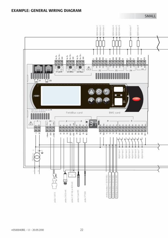
22+0500040ML - 1.1 - 20.09.2010
EXAMPLE: GENERAL WIRING DIAGRAM
G G0
230/
24 V
ac
M
OU
T +V
anal
og o
utpu
t 1 (0
/10
Vdc)
anal
og o
utpu
t 2 (0
/10
Vdc)
anal
og o
utpu
t 3 (0
/10
Vdc)
anal
og o
utpu
t 4 (0
/10
Vdc)
L N
digi
tal o
utpu
t 1di
gita
l out
put 2
digi
tal o
utpu
t 3
digi
tal o
utpu
t 4
digi
tal in
put 1
digi
tal in
put 2
digi
tal in
put 3
digi
tal in
put 4
digi
tal in
put 5
digi
tal in
put 6
digi
tal in
put 7
digi
tal in
put 8
digi
tal o
utpu
t 5di
gita
l out
put 6
digi
tal o
utpu
t 7
digi
tal o
utpu
t 8
prob
e 1 (0
/5 V
)
prob
e 2 (4
/20 m
A)
prob
e 3 (0
/1 Vd
c or 4
/20 m
A)
prob
e 4 C
arel
NTC
prob
e 5 PT
1000
Rx-/
Tx-
Rx+
/Tx+
GND
C1 NO1
NO2
NO3
C1 C4 NO4
NO5
NO6
C4 C7 NO7
C7 NO8
C8 NC8
G G0 B1 B2 B3
GND
+VD
C
+Vt
erm
GND
+5
VREF B4 BC
4 B5 BC5 VG VG0 Y1 Y2 Y3 Y4 ID1
ID2
ID3
ID4
ID5
ID6
ID7
ID8
IDC1
SMALL
C1
NO1
NO2
NO3 C1 C4
NO4
NO5
NO6 C4 C7
NO7 C7
NO8 C8
NC8
G G0 B1 B2 B3 GND
+VD
C
+Vt
erm
GND
+5
VREF
B4 BC4
B5 BC5
VG VG0
Y1 Y2 Y3 Y4 ID1
ID2
ID3
ID4
ID5
ID6
ID7
ID8
IDC1
B6 B7 B8 GND
J1 J24 J2 J3 J4 J5
J14J11 pLAN
J10J9
J13J12 J16J15
J6
Fie ldBus card BMS card
J25 BMS2 J26 FBus2
input: 24 V 50...60 Hz / 28...36 Vmax. power: 45 VA/20 W
Rx-/
Tx-
Rx+
/Tx+
GND
Rx-/
Tx-
Rx+
/Tx+
GND
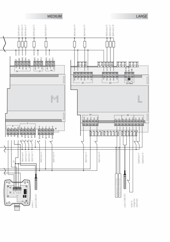
anal
og o
utpu
t 5 (0
/10
Vdc)
digi
tal in
put 1
5
digi
tal in
put 1
6
digi
tal in
put 1
7
digi
tal in
put 1
8
digi
tal o
utpu
t 14
digi
tal o
utpu
t 15
digi
tal o
utpu
t 16
digi
tal o
utpu
t 17
digi
tal o
utpu
t 18
prob
e 9 C
AREL
NTC
prob
e 10
volta
ge-fr
eedi
gita
l inpu
t
anal
og o
utpu
t 6 (0
/10
Vdc)
out H M
NTC
NTC
+ (G
)di
gita
l inpu
t 9
CP digi
tal in
put 1
0di
gita
l inpu
t 11
digi
tal in
put 1
2
digi
tal in
put 1
3
digi
tal in
put 1
4
digi
tal o
utpu
t 9
digi
tal o
utpu
t 10
digi
tal o
utpu
t 11
digi
tal o
utpu
t 12
digi
tal o
utpu
t 13
prob
e 8 C
AREL
NTC
prob
e 6 -
7N
O12
C12
NC1
2
NO1
3
C13
NC1
3
C9 NO9
NO1
0
NO1
1
C9
B6 B7 B8
GND
ID9
ID10
ID11
ID12
IDC9
ID13
H
ID13
IDC1
3
ID14
ID14
H
MEDIUM LARGE
J20
J21 J22
J19
NO1
4
C14
NC1
4
NO1
5
C15
NC1
5
C16
NO1
6
NO1
7
NO1
8
C16
ID15
H
ID15
IDC1
5
ID16
ID16
H
Y5 Y6 ID17
ID18
IDC1
7
B9 BC9
B10
BC10
J23 FBus2
NO1
2
C12
NC1
2
NO1
3
C13
NC1
3C9
NO9
NO1
0
NO1
1 C9
B6 B7 B8 GND
ID9
ID10
ID11
ID12
IDC9
ID13
H
ID13
IDC1
3
ID14
ID14
H
J7
J8
J16 J17 J18
J6Rx
-/Tx
-
Rx+
/Tx+
GND

24+0500040ML - 1.1 - 20.09.2010
IMPORTANT WARNINGSThe CAREL product is a state-of-the-art device, whose operation is specifi ed in the technical documentation supplied with the product or can be downloaded, even prior to purchase, from the website www.carel.com.The customer (manufacturer, developer or installer of the fi nal equipment) accepts all liability and risk relating to the confi guration of the product in order to reach the expected results in relation to the specifi c fi nal installation and/or equipment.The failure to complete such phase, which is required/indicated in the user manual, may cause the fi nal product to malfunction; CAREL accepts no liability in such cases.The customer must use the product only in the manner described in the documentation relating to the product.The liability of CAREL in relation to its products is specifi ed in the CAREL general contract conditions, available on the website www.carel.com and/or by specifi c agreements with customers.

25+0500040ML - 1.1 - 20.09.2010

26+0500040ML - 1.1 - 20.09.2010


CAREL INDUSTRIES HQsVia dell’Industria, 11 - 35020 Brugine - Padova (Italy)
Tel. (+39) 049.9716611 - Fax (+39) 049.9716600
e-mail: [email protected] - www.CAREL.com
+050
0040
ML
- 1.1
- 20.
09.2
010