Embed Size (px)
Citation preview
Autodesk AutoCAD 2007:
Fundamentals
Elise Moss
SDC
Schroff Development Corporation
www.schroff.com
www.schroff-europe.com
PUBLICATIONS
Copyrighted Material
Copyrighted
Material
Copyrighted Material
Copyrighted
Material
Autodesk AutoCAD 2007: Fundamentals
3-1
Lesson 3 – Drawing Lines Estimated Class Time: 2 Hours
Objectives
This section introduces AutoCAD commands, for creating a simple drawing. Starting with a New drawing, the user will learn to draw lines using different methods.
• Start From Scratch
Use the New command to begin a new drawing from “scratch”.
• Line
Draw line segments.
• Line
Using Direct Distance Method
• Line
Using Polar Tracking
• Line
Using Cartesian Coordinates
• Line
Absolute Coordinates
• Line
Relative Coordinates
• Line
Polar Coordinates
• Line
Drag Method
• Erase
Deleting AutoCAD entities
Copyrighted Material
Copyrighted
Material
Copyrighted Material
Copyrighted
Material
Autodesk AutoCAD 2007: Fundamentals
3-2
SS tt aa rr tt ff rr oo mm SS cc rr aa tt cc hh
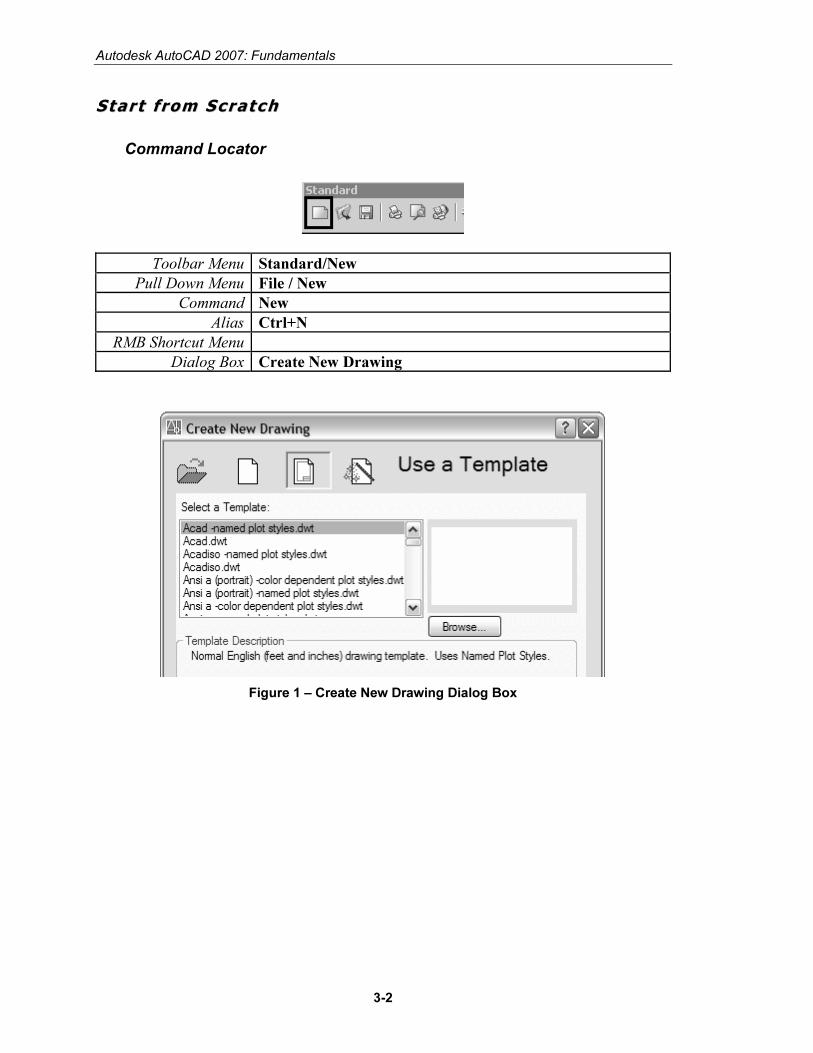
Command Locator
Toolbar Menu Standard/New
Pull Down Menu File / New
Command New
Alias Ctrl+N
RMB Shortcut Menu
Dialog Box Create New Drawing
Figure 1 – Create New Drawing Dialog Box
Copyrighted Material
Copyrighted
Material
Copyrighted Material
Copyrighted
Material
Drawing Lines
3-3
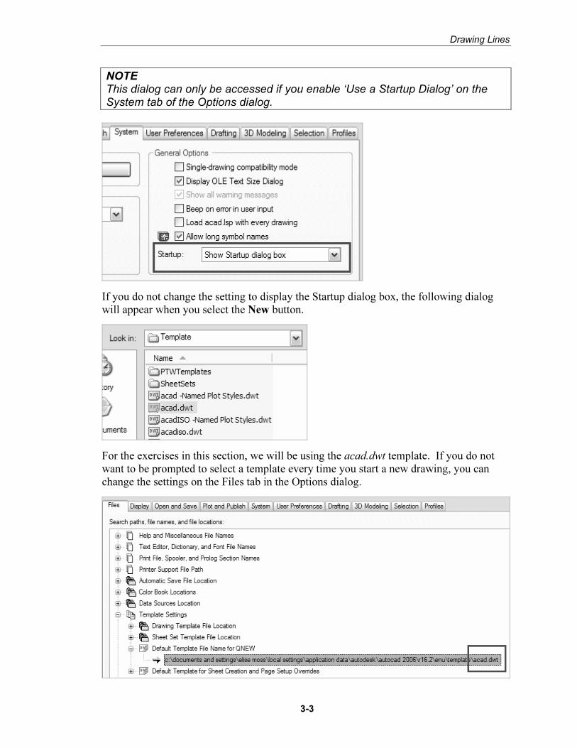
NOTE This dialog can only be accessed if you enable ‘Use a Startup Dialog’ on the System tab of the Options dialog.
If you do not change the setting to display the Startup dialog box, the following dialog will appear when you select the New button.
For the exercises in this section, we will be using the acad.dwt template. If you do not want to be prompted to select a template every time you start a new drawing, you can change the settings on the Files tab in the Options dialog.
Copyrighted Material
Copyrighted
Material
Copyrighted Material
Copyrighted
Material
Autodesk AutoCAD 2007: Fundamentals
3-4
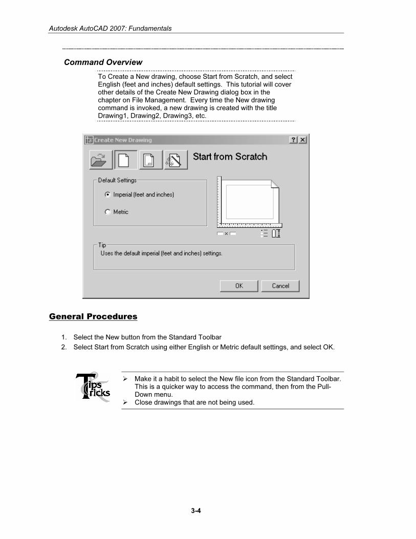
Command Overview
To Create a New drawing, choose Start from Scratch, and select English (feet and inches) default settings. This tutorial will cover other details of the Create New Drawing dialog box in the chapter on File Management. Every time the New drawing command is invoked, a new drawing is created with the title Drawing1, Drawing2, Drawing3, etc.
General Procedures
1. Select the New button from the Standard Toolbar
2. Select Start from Scratch using either English or Metric default settings, and select OK.
� Make it a habit to select the New file icon from the Standard Toolbar. This is a quicker way to access the command, then from the Pull-Down menu.
� Close drawings that are not being used.
Copyrighted Material
Copyrighted
Material
Copyrighted Material
Copyrighted
Material
Drawing Lines
3-5
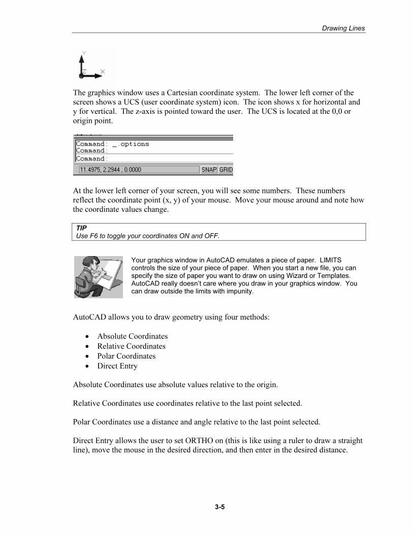
The graphics window uses a Cartesian coordinate system. The lower left corner of the screen shows a UCS (user coordinate system) icon. The icon shows x for horizontal and y for vertical. The z-axis is pointed toward the user. The UCS is located at the 0,0 or origin point.
At the lower left corner of your screen, you will see some numbers. These numbers reflect the coordinate point (x, y) of your mouse. Move your mouse around and note how the coordinate values change. TIP Use F6 to toggle your coordinates ON and OFF.
Your graphics window in AutoCAD emulates a piece of paper. LIMITS controls the size of your piece of paper. When you start a new file, you can specify the size of paper you want to draw on using Wizard or Templates. AutoCAD really doesn’t care where you draw in your graphics window. You can draw outside the limits with impunity.
AutoCAD allows you to draw geometry using four methods:
• Absolute Coordinates
• Relative Coordinates
• Polar Coordinates
• Direct Entry Absolute Coordinates use absolute values relative to the origin. Relative Coordinates use coordinates relative to the last point selected. Polar Coordinates use a distance and angle relative to the last point selected. Direct Entry allows the user to set ORTHO on (this is like using a ruler to draw a straight line), move the mouse in the desired direction, and then enter in the desired distance.
Copyrighted Material
Copyrighted
Material
Copyrighted Material
Copyrighted
Material
Autodesk AutoCAD 2007: Fundamentals
3-6
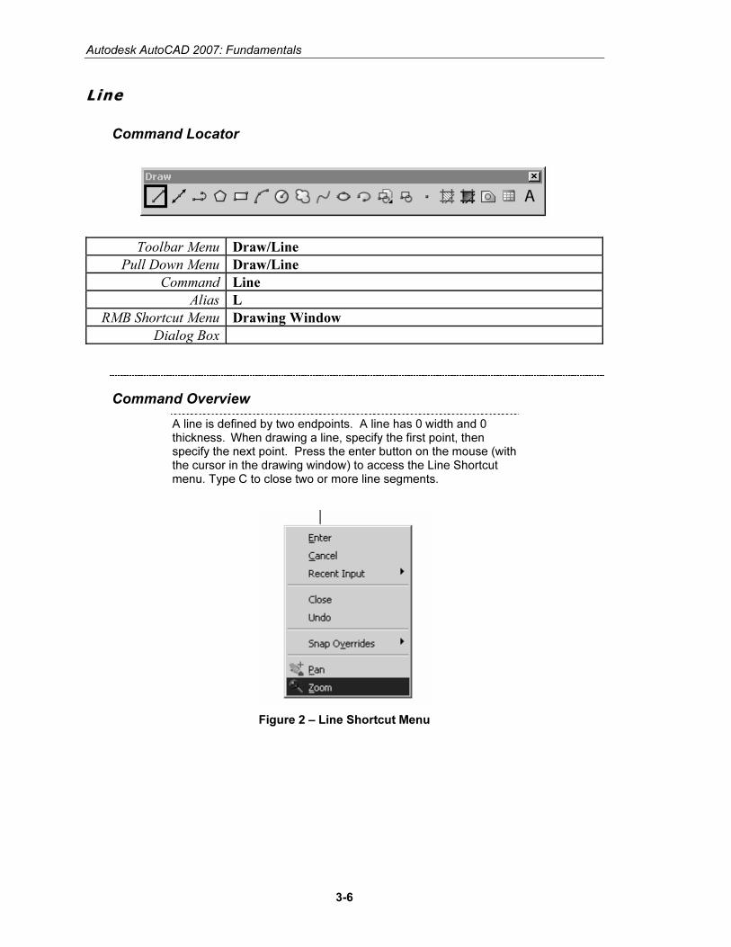
LL ii nn ee
Command Locator
Toolbar Menu Draw/Line
Pull Down Menu Draw/Line
Command Line
Alias L
RMB Shortcut Menu Drawing Window
Dialog Box
Command Overview
A line is defined by two endpoints. A line has 0 width and 0 thickness. When drawing a line, specify the first point, then specify the next point. Press the enter button on the mouse (with the cursor in the drawing window) to access the Line Shortcut menu. Type C to close two or more line segments.
Figure 2 – Line Shortcut Menu
Copyrighted Material
Copyrighted
Material
Copyrighted Material
Copyrighted
Material
Drawing Lines
3-7
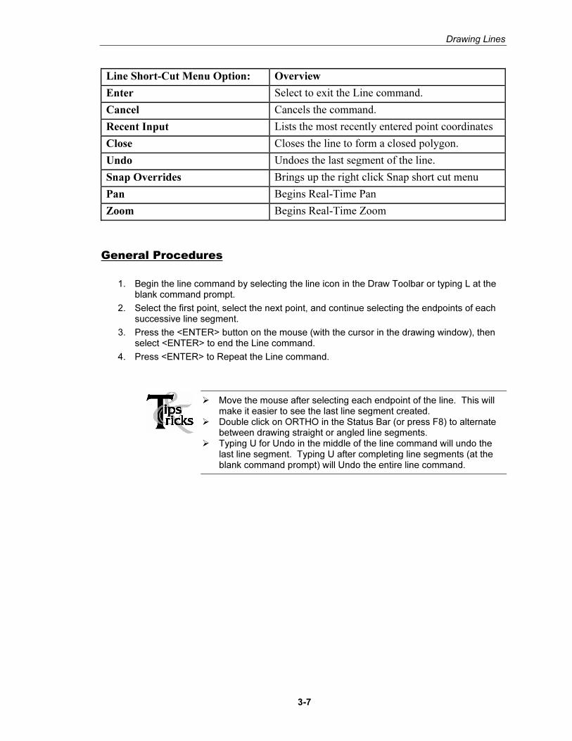
Line Short-Cut Menu Option: Overview
Enter Select to exit the Line command.
Cancel Cancels the command.
Recent Input Lists the most recently entered point coordinates
Close Closes the line to form a closed polygon.
Undo Undoes the last segment of the line.
Snap Overrides Brings up the right click Snap short cut menu
Pan Begins Real-Time Pan
Zoom Begins Real-Time Zoom
General Procedures
1. Begin the line command by selecting the line icon in the Draw Toolbar or typing L at the blank command prompt.
2. Select the first point, select the next point, and continue selecting the endpoints of each successive line segment.
3. Press the <ENTER> button on the mouse (with the cursor in the drawing window), then select <ENTER> to end the Line command.
4. Press <ENTER> to Repeat the Line command.
� Move the mouse after selecting each endpoint of the line. This will make it easier to see the last line segment created.
� Double click on ORTHO in the Status Bar (or press F8) to alternate between drawing straight or angled line segments.
� Typing U for Undo in the middle of the line command will undo the last line segment. Typing U after completing line segments (at the blank command prompt) will Undo the entire line command.
Copyrighted Material
Copyrighted
Material
Copyrighted Material
Copyrighted
Material
Autodesk AutoCAD 2007: Fundamentals
3-8
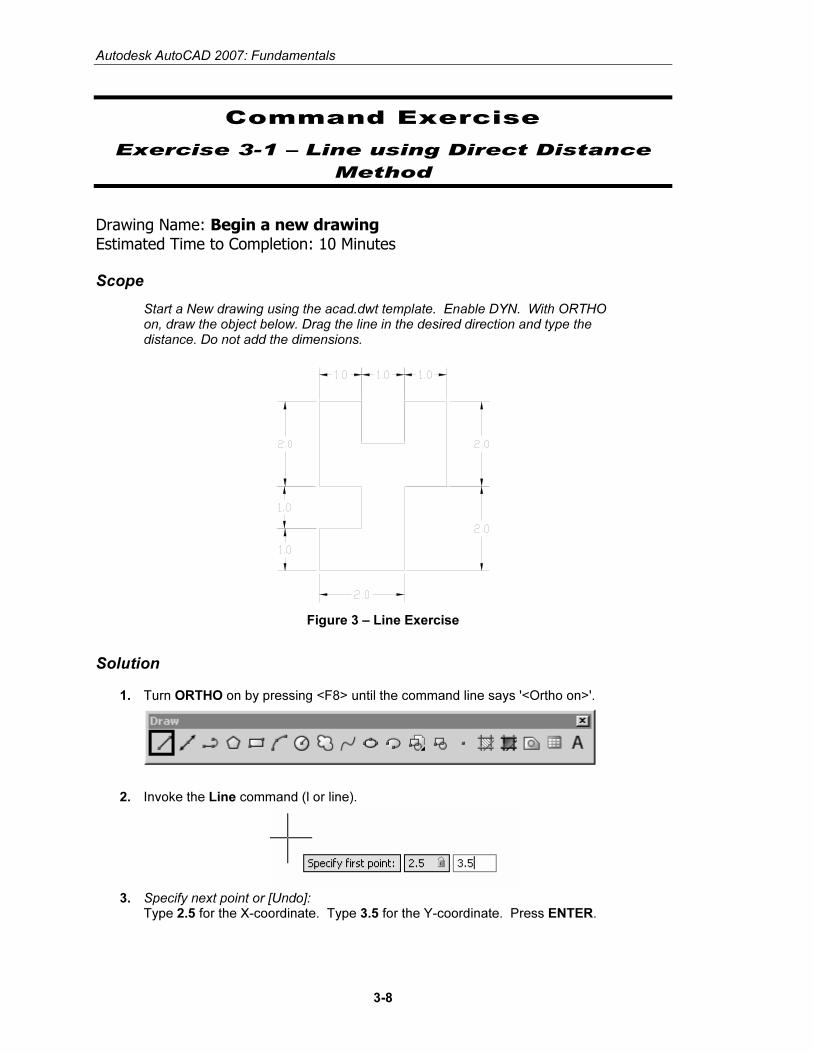
Command Exercise
Exercise 3-1 – Line using Direct Distance
Method
Drawing Name: Begin a new drawing Estimated Time to Completion: 10 Minutes
Scope
Start a New drawing using the acad.dwt template. Enable DYN. With ORTHO on, draw the object below. Drag the line in the desired direction and type the distance. Do not add the dimensions.
Figure 3 – Line Exercise
Solution
1. Turn ORTHO on by pressing <F8> until the command line says '<Ortho on>'.
2. Invoke the Line command (l or line).
3. Specify next point or [Undo]: Type 2.5 for the X-coordinate. Type 3.5 for the Y-coordinate. Press ENTER.
Copyrighted Material
Copyrighted
Material
Copyrighted Material
Copyrighted
Material
Drawing Lines
3-9
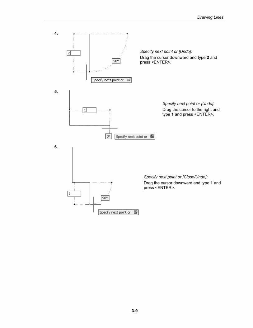
4.
Specify next point or [Undo]:
Drag the cursor downward and type 2 and press <ENTER>.
5.
Specify next point or [Undo]:
Drag the cursor to the right and type 1 and press <ENTER>.
6.
Specify next point or [Close/Undo]:
Drag the cursor downward and type 1 and press <ENTER>.
Copyrighted Material
Copyrighted
Material
Copyrighted Material
Copyrighted
Material
Autodesk AutoCAD 2007: Fundamentals
3-10
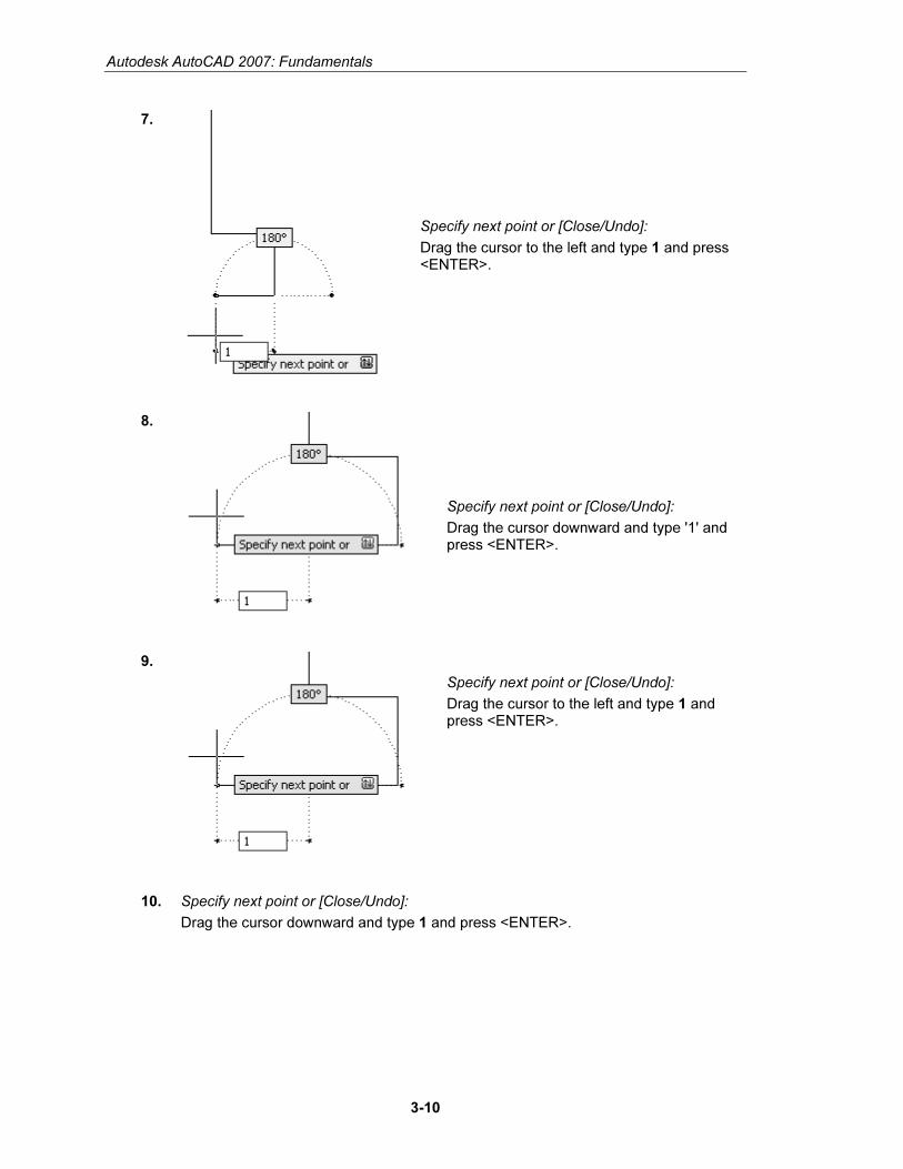
7.
Specify next point or [Close/Undo]:
Drag the cursor to the left and type 1 and press <ENTER>.
8.
Specify next point or [Close/Undo]:
Drag the cursor downward and type '1' and press <ENTER>.
9.
Specify next point or [Close/Undo]:
Drag the cursor to the left and type 1 and press <ENTER>.
10. Specify next point or [Close/Undo]:
Drag the cursor downward and type 1 and press <ENTER>.
Copyrighted Material
Copyrighted
Material
Copyrighted Material
Copyrighted
Material
Drawing Lines
3-11
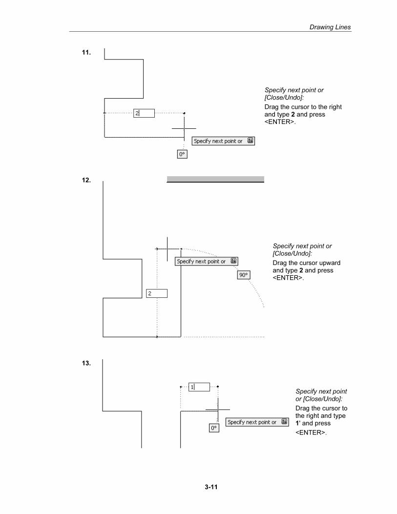
11.
Specify next point or [Close/Undo]:
Drag the cursor to the right and type 2 and press <ENTER>.
12.
Specify next point or [Close/Undo]:
Drag the cursor upward and type 2 and press <ENTER>.
13.
Specify next point or [Close/Undo]:
Drag the cursor to the right and type 1' and press
<ENTER>.
Copyrighted Material
Copyrighted
Material
Copyrighted Material
Copyrighted
Material
Autodesk AutoCAD 2007: Fundamentals
3-12
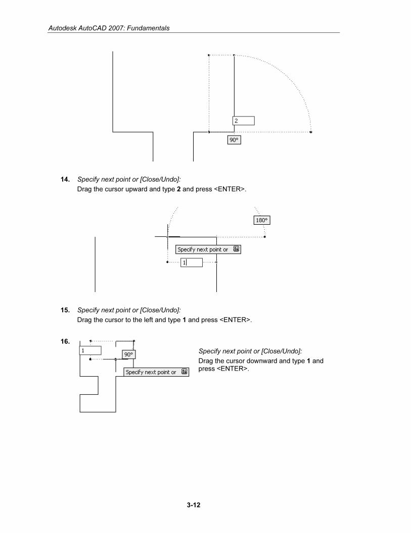
14. Specify next point or [Close/Undo]:
Drag the cursor upward and type 2 and press <ENTER>.
15. Specify next point or [Close/Undo]:
Drag the cursor to the left and type 1 and press <ENTER>.
16.
Specify next point or [Close/Undo]:
Drag the cursor downward and type 1 and press <ENTER>.
Copyrighted Material
Copyrighted
Material
Copyrighted Material
Copyrighted
Material
Drawing Lines
3-13
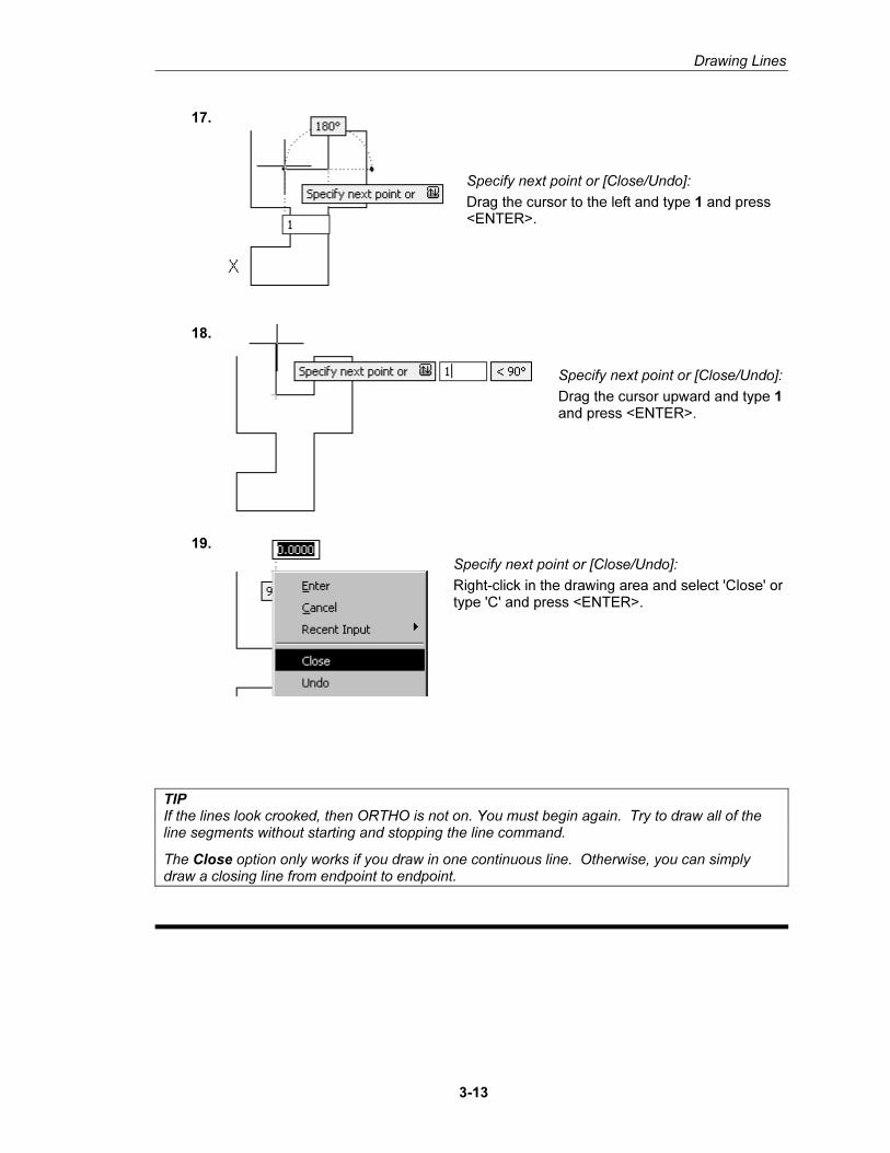
17.
Specify next point or [Close/Undo]:
Drag the cursor to the left and type 1 and press <ENTER>.
18.
Specify next point or [Close/Undo]:
Drag the cursor upward and type 1 and press <ENTER>.
19.
Specify next point or [Close/Undo]:
Right-click in the drawing area and select 'Close' or type 'C' and press <ENTER>.
TIP If the lines look crooked, then ORTHO is not on. You must begin again. Try to draw all of the line segments without starting and stopping the line command.
The Close option only works if you draw in one continuous line. Otherwise, you can simply draw a closing line from endpoint to endpoint.
Copyrighted Material
Copyrighted
Material
Copyrighted Material
Copyrighted
Material
Autodesk AutoCAD 2007: Fundamentals
3-14
Command Exercise
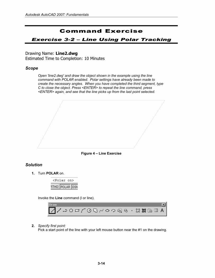
Exercise 3-2 – Line Using Polar Tracking
Drawing Name: Line2.dwg Estimated Time to Completion: 10 Minutes
Scope
Open 'line2.dwg' and draw the object shown in the example using the line command with POLAR enabled. Polar settings have already been made to create the necessary angles. When you have completed the third segment, type C to close the object. Press <ENTER> to repeat the line command, press <ENTER> again, and see that the line picks up from the last point selected.
Figure 4 – Line Exercise
Solution
1. Turn POLAR on.
Invoke the Line command (l or line).
2. Specify first point: Pick a start point of the line with your left mouse button near the #1 on the drawing.
Copyrighted Material
Copyrighted
Material
Copyrighted Material
Copyrighted
Material
Drawing Lines
3-15
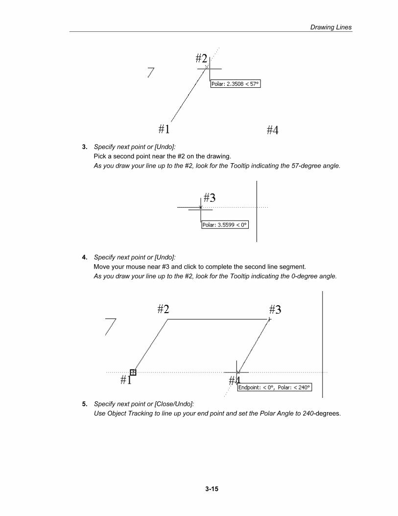
3. Specify next point or [Undo]:
Pick a second point near the #2 on the drawing.
As you draw your line up to the #2, look for the Tooltip indicating the 57-degree angle.
4. Specify next point or [Undo]:
Move your mouse near #3 and click to complete the second line segment.
As you draw your line up to the #2, look for the Tooltip indicating the 0-degree angle.
5. Specify next point or [Close/Undo]:
Use Object Tracking to line up your end point and set the Polar Angle to 240-degrees.
Copyrighted Material
Copyrighted
Material
Copyrighted Material
Copyrighted
Material
Autodesk AutoCAD 2007: Fundamentals
3-16
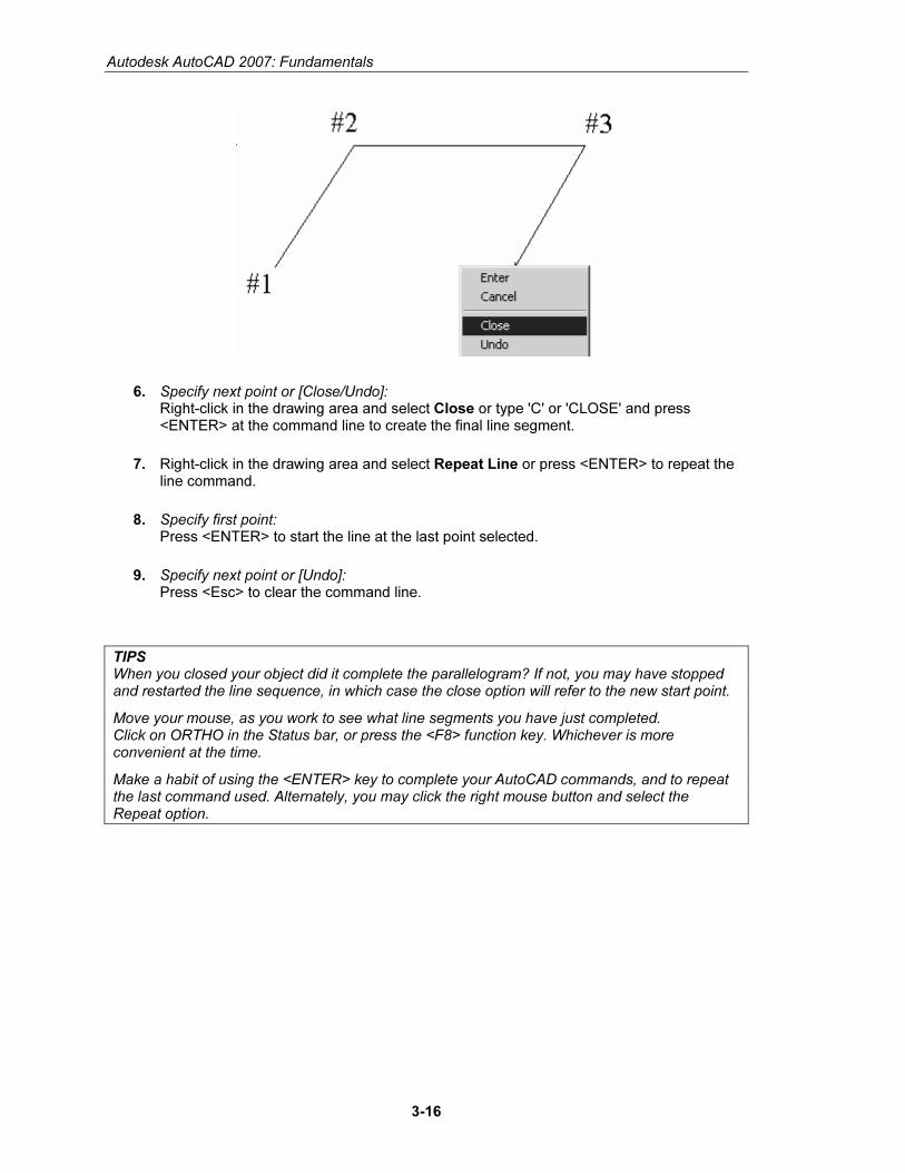
6. Specify next point or [Close/Undo]: Right-click in the drawing area and select Close or type 'C' or 'CLOSE' and press <ENTER> at the command line to create the final line segment.
7. Right-click in the drawing area and select Repeat Line or press <ENTER> to repeat the line command.
8. Specify first point: Press <ENTER> to start the line at the last point selected.
9. Specify next point or [Undo]: Press <Esc> to clear the command line.
TIPS When you closed your object did it complete the parallelogram? If not, you may have stopped and restarted the line sequence, in which case the close option will refer to the new start point.
Move your mouse, as you work to see what line segments you have just completed. Click on ORTHO in the Status bar, or press the <F8> function key. Whichever is more convenient at the time.
Make a habit of using the <ENTER> key to complete your AutoCAD commands, and to repeat the last command used. Alternately, you may click the right mouse button and select the Repeat option.
Copyrighted Material
Copyrighted
Material
Copyrighted Material
Copyrighted
Material
Drawing Lines
3-17
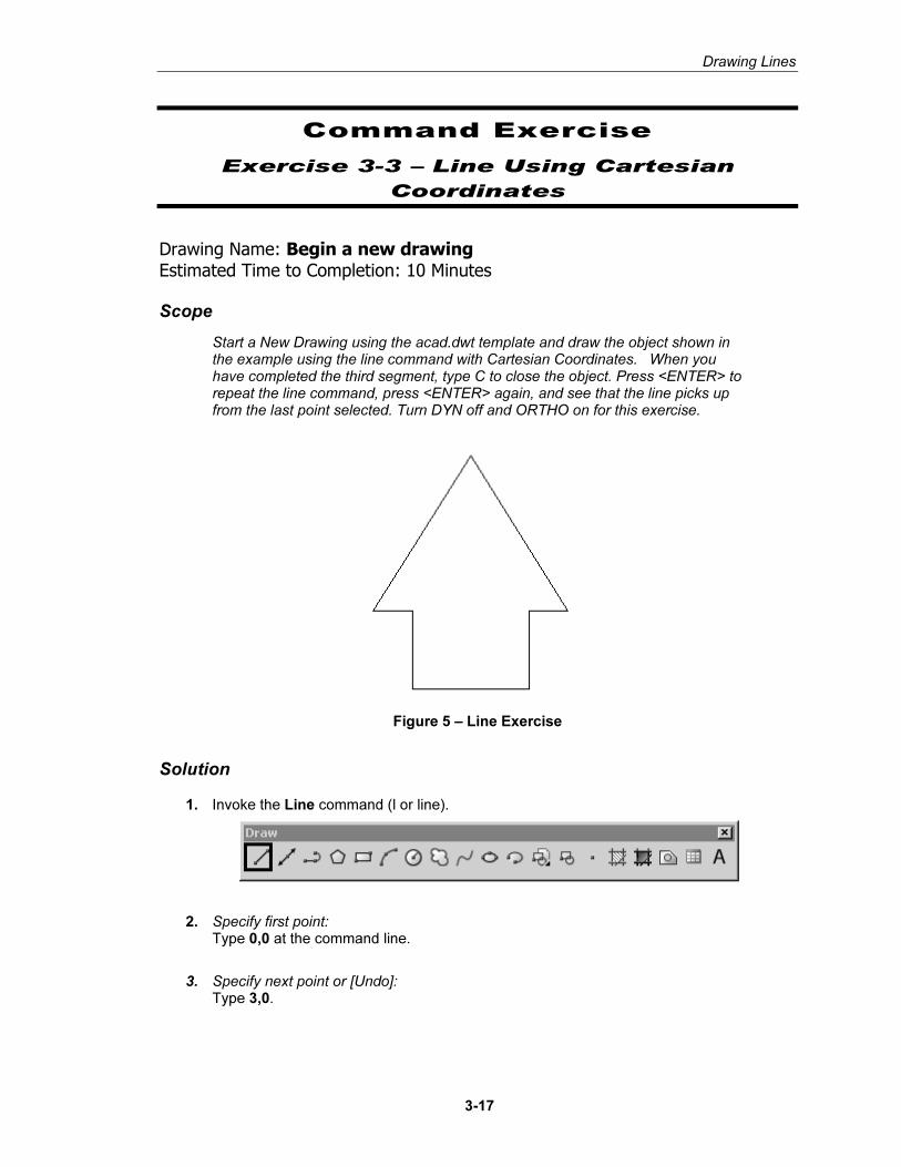
Command Exercise
Exercise 3-3 – Line Using Cartesian
Coordinates
Drawing Name: Begin a new drawing Estimated Time to Completion: 10 Minutes
Scope
Start a New Drawing using the acad.dwt template and draw the object shown in the example using the line command with Cartesian Coordinates. When you have completed the third segment, type C to close the object. Press <ENTER> to repeat the line command, press <ENTER> again, and see that the line picks up from the last point selected. Turn DYN off and ORTHO on for this exercise.
Figure 5 – Line Exercise
Solution
1. Invoke the Line command (l or line).
2. Specify first point: Type 0,0 at the command line.
3. Specify next point or [Undo]: Type 3,0.
Copyrighted Material
Copyrighted
Material
Copyrighted Material
Copyrighted
Material
Autodesk AutoCAD 2007: Fundamentals
3-18
4. Specify next point or [Undo]: 3,2
5. Specify next point or [Close/Undo]: 4,2
6. Specify next point or [Close/Undo]: 1.5,6
7. Specify next point or [Close/Undo]: -1,2
8. Specify next point or [Close/Undo]: 0,2
9. Specify next point or [Close/Undo]: Right-click in the drawing area and select 'Close' or type 'C' or 'CLOSE' and press <ENTER> at the command line to create the final line segment.
CC oo oo rr dd ii nn aa tt ee EE nn tt rr yy
Command Locator
Toolbar Menu
Pull Down Menu
Command Type coordinates
Alias
RMB Shortcut Menu
Dialog Box
Command Overview
Once the Units have been established, coordinates can be typed to specify points or distances. Always draw full scale. There are four ways to specify coordinates: absolute, relative, polar, and direct distance.
Copyrighted Material
Copyrighted
Material
Copyrighted Material
Copyrighted
Material
Drawing Lines
3-19
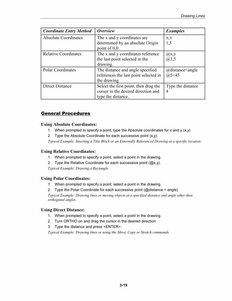
Coordinate Entry Method Overview Examples
Absolute Coordinates The x and y coordinates are determined by an absolute Origin point of 0,0.
X,Y 1,5
Relative Coordinates The x and y coordinates reference the last point selected in the drawing.
@x,y @3,5
Polar Coordinates The distance and angle specified references the last point selected in the drawing
@distance<angle @5<45
Direct Distance Select the first point, then drag the cursor in the desired direction and type the distance.
Type the distance 4
General Procedures
Using Absolute Coordinates:
1. When prompted to specify a point, type the Absolute coordinates for x and y (x,y)
2. Type the Absolute Coordinate for each successive point (x,y).
Typical Example: Inserting a Title Block or an Externally Referenced Drawing at a specific location.
Using Relative Coordinates:
1. When prompted to specify a point, select a point in the drawing.
2. Type the Relative Coordinate for each successive point (@x,y).
Typical Example: Drawing a Rectangle.
Using Polar Coordinates:
1. When prompted to specify a point, select a point in the drawing.
2. Type the Polar Coordinate for each successive point (@distance < angle).
Typical Example: Drawing lines or moving objects at a specified distance and angle other then
orthogonal angles.
Using Direct Distance:
1. When prompted to specify a point, select a point in the drawing.
2. Turn ORTHO on and drag the cursor in the desired direction.
3. Type the distance and press <ENTER>.
Typical Example: Drawing lines or using the Move, Copy or Stretch commands.
Copyrighted Material
Copyrighted
Material
Copyrighted Material
Copyrighted
Material
Autodesk AutoCAD 2007: Fundamentals
3-20
� Always use object snap for selecting specific points in the drawing. � Remember to separate the x and y coordinates by a comma.
Example: 1,5 means the absolute coordinate where x=1 and y=5. � It is not necessary to type the z coordinate when z = 0. � Angles are typically measured counter-clockwise. Angle 0 is typically
East. � Precede Relative and Polar coordinate information with an @ sign
(over the number 2 on the keyboard). � ORTHO should be on when using the direct distance method. � When drawing lines, or moving objects at specific angles(other than
with ORTHO on), type the polar coordinate (example: @10<45) or use Polar Tracking Settings.
� Typing the minimum number of keystrokes is important for drawing efficiently. AutoCAD will fill in leading and trailing zeros and the appropriate Unit endings.
� AutoCAD will convert decimal equivalents to feet and inches. � AutoCAD will assume inches, unless the foot mark ' is typed. � The Coordinates Display can be turned on or off from the Status Bar
by double clicking on it (LMB). If in the middle of a Draw or Modify command, a third option will display the distance and <angle.
� The DYN toggle can be used to display and enter coordinates.
Copyrighted Material
Copyrighted
Material
Copyrighted Material
Copyrighted
Material
Drawing Lines
3-21
Command Exercise
Exercise 3-4 – Absolute Coordinates
Drawing Name: entry1.dwg Estimated Time to Completion: 5 Minutes
Scope
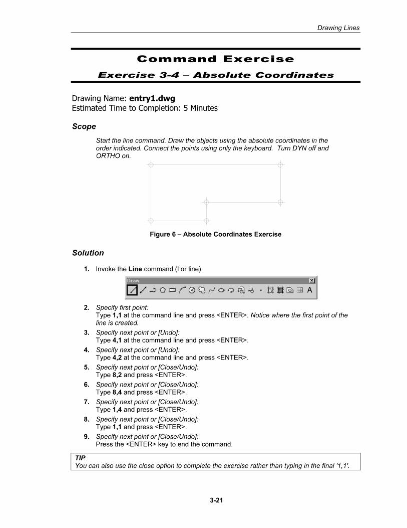
Start the line command. Draw the objects using the absolute coordinates in the order indicated. Connect the points using only the keyboard. Turn DYN off and ORTHO on.
Figure 6 – Absolute Coordinates Exercise
Solution
1. Invoke the Line command (l or line).
2. Specify first point: Type 1,1 at the command line and press <ENTER>. Notice where the first point of the line is created.
3. Specify next point or [Undo]: Type 4,1 at the command line and press <ENTER>.
4. Specify next point or [Undo]: Type 4,2 at the command line and press <ENTER>.
5. Specify next point or [Close/Undo]: Type 8,2 and press <ENTER>.
6. Specify next point or [Close/Undo]: Type 8,4 and press <ENTER>.
7. Specify next point or [Close/Undo]: Type 1,4 and press <ENTER>.
8. Specify next point or [Close/Undo]: Type 1,1 and press <ENTER>.
9. Specify next point or [Close/Undo]: Press the <ENTER> key to end the command.
TIP You can also use the close option to complete the exercise rather than typing in the final '1,1'.
Copyrighted Material
Copyrighted
Material
Copyrighted Material
Copyrighted
Material
Autodesk AutoCAD 2007: Fundamentals
3-22
Command Exercise
Exercise 3-5 – Absolute Coordinates
Drawing Name: new drawing Estimated Time to Completion: 5 Minutes
Scope
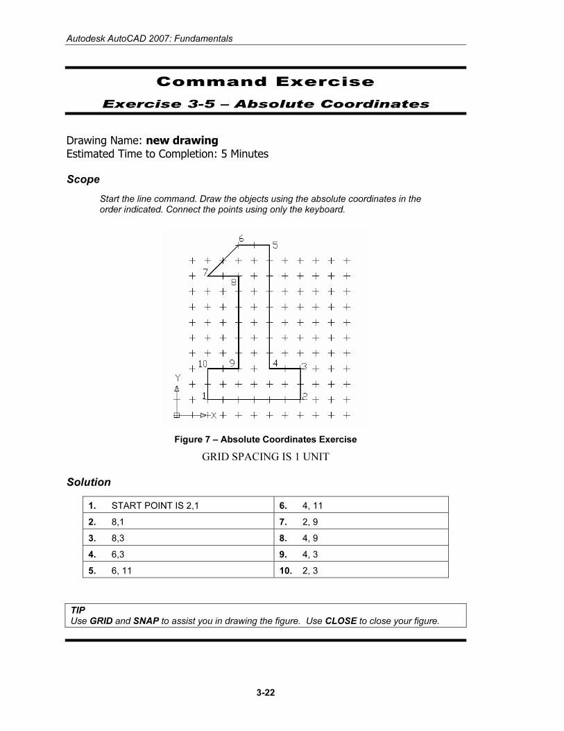
Start the line command. Draw the objects using the absolute coordinates in the order indicated. Connect the points using only the keyboard.
Figure 7 – Absolute Coordinates Exercise
GRID SPACING IS 1 UNIT
Solution
1. START POINT IS 2,1 6. 4, 11
2. 8,1 7. 2, 9
3. 8,3 8. 4, 9
4. 6,3 9. 4, 3
5. 6, 11 10. 2, 3
TIP Use GRID and SNAP to assist you in drawing the figure. Use CLOSE to close your figure.
Copyrighted Material
Copyrighted
Material
Copyrighted Material
Copyrighted
Material
Drawing Lines
3-23
Command Exercise
Exercise 3-6 – Relative Coordinates
Drawing Name: entry2.dwg Estimated Time to Completion: 5 Minutes
Scope
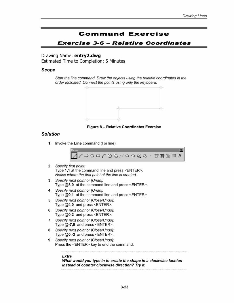
Start the line command. Draw the objects using the relative coordinates in the order indicated. Connect the points using only the keyboard.
Figure 8 – Relative Coordinates Exercise
Solution
1. Invoke the Line command (l or line).
2. Specify first point: Type 1,1 at the command line and press <ENTER>. Notice where the first point of the line is created.
3. Specify next point or [Undo]: Type @3,0 at the command line and press <ENTER>.
4. Specify next point or [Undo]: Type @0,1 at the command line and press <ENTER>.
5. Specify next point or [Close/Undo]: Type @4,0 and press <ENTER>.
6. Specify next point or [Close/Undo]: Type @0,2 and press <ENTER>.
7. Specify next point or [Close/Undo]: Type @-7,0 and press <ENTER>.
8. Specify next point or [Close/Undo]: Type @0,-3 and press <ENTER>.
9. Specify next point or [Close/Undo]: Press the <ENTER> key to end the command.
Extra What would you type in to create the shape in a clockwise fashion instead of counter clockwise direction? Try It.
Copyrighted Material
Copyrighted
Material
Copyrighted Material
Copyrighted
Material
Autodesk AutoCAD 2007: Fundamentals
3-24
Command Exercise
Exercise 3-7 – Relative Coordinates
Drawing Name: new drawing Estimated Time to Completion: 5 Minutes
Scope
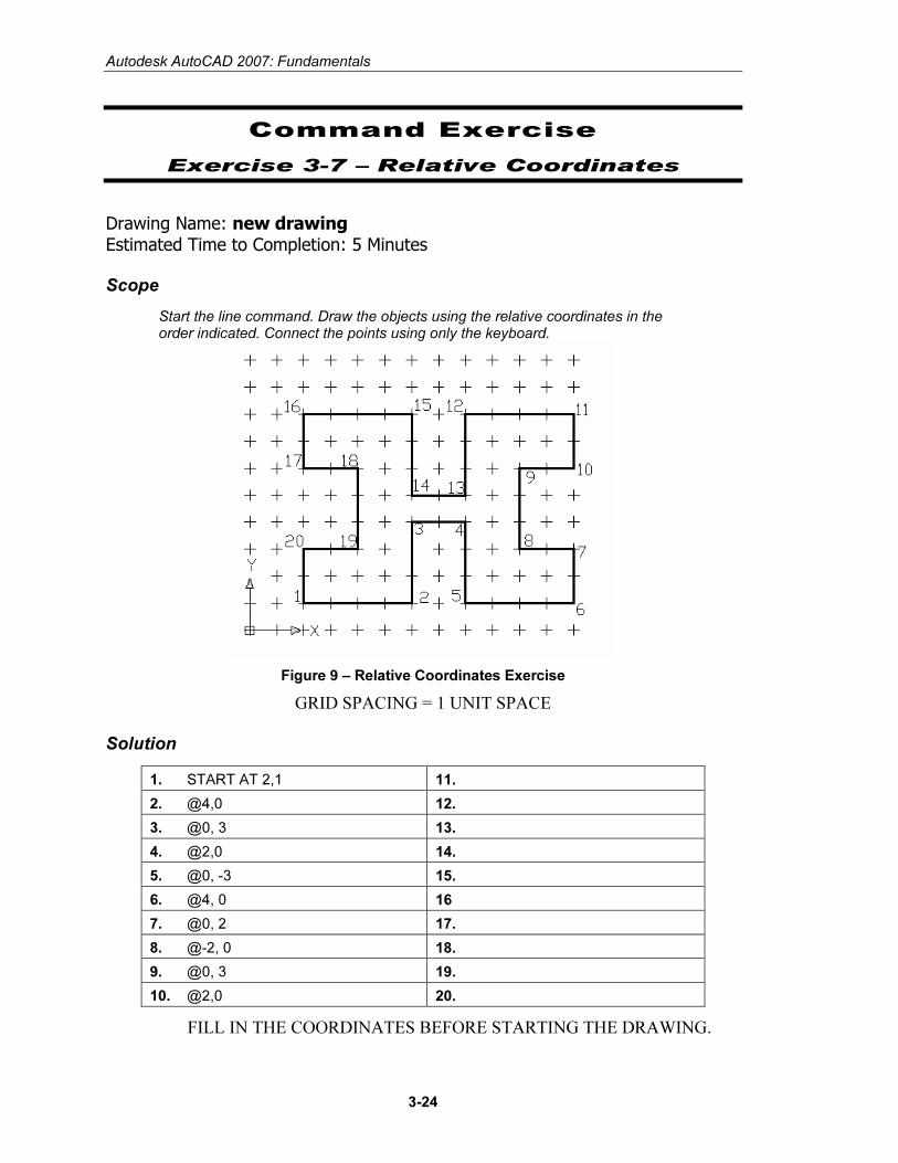
Start the line command. Draw the objects using the relative coordinates in the order indicated. Connect the points using only the keyboard.
Figure 9 – Relative Coordinates Exercise
GRID SPACING = 1 UNIT SPACE
Solution
1. START AT 2,1 11.
2. @4,0 12.
3. @0, 3 13.
4. @2,0 14.
5. @0, -3 15.
6. @4, 0 16
7. @0, 2 17.
8. @-2, 0 18.
9. @0, 3 19.
10. @2,0 20.
FILL IN THE COORDINATES BEFORE STARTING THE DRAWING.
Copyrighted Material
Copyrighted
Material
Copyrighted Material
Copyrighted
Material
Drawing Lines
3-25
Command Exercise
Exercise 3-8 – Polar Coordinates
Drawing Name: entry3.dwg Estimated Time to Completion: 5 Minutes
Scope
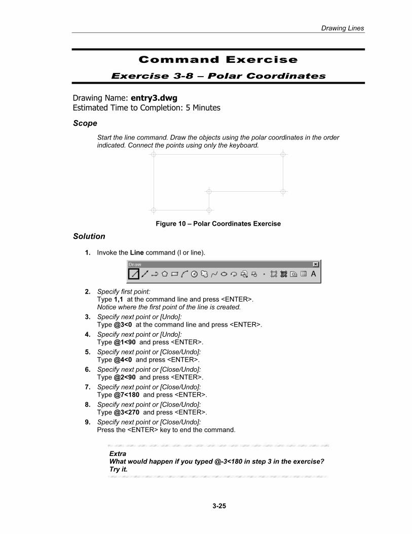
Start the line command. Draw the objects using the polar coordinates in the order indicated. Connect the points using only the keyboard.
Figure 10 – Polar Coordinates Exercise
Solution
1. Invoke the Line command (l or line).
2. Specify first point: Type 1,1 at the command line and press <ENTER>. Notice where the first point of the line is created.
3. Specify next point or [Undo]: Type @3<0 at the command line and press <ENTER>.
4. Specify next point or [Undo]: Type @1<90 and press <ENTER>.
5. Specify next point or [Close/Undo]: Type @4<0 and press <ENTER>.
6. Specify next point or [Close/Undo]: Type @2<90 and press <ENTER>.
7. Specify next point or [Close/Undo]: Type @7<180 and press <ENTER>.
8. Specify next point or [Close/Undo]: Type @3<270 and press <ENTER>.
9. Specify next point or [Close/Undo]: Press the <ENTER> key to end the command.
Extra What would happen if you typed @-3<180 in step 3 in the exercise? Try it.
Copyrighted Material
Copyrighted
Material
Copyrighted Material
Copyrighted
Material
Autodesk AutoCAD 2007: Fundamentals
3-26
Command Exercise
Exercise 3-9 – Polar Coordinates
Drawing Name: new drawing Estimated Time to Completion: 5 Minutes
Scope
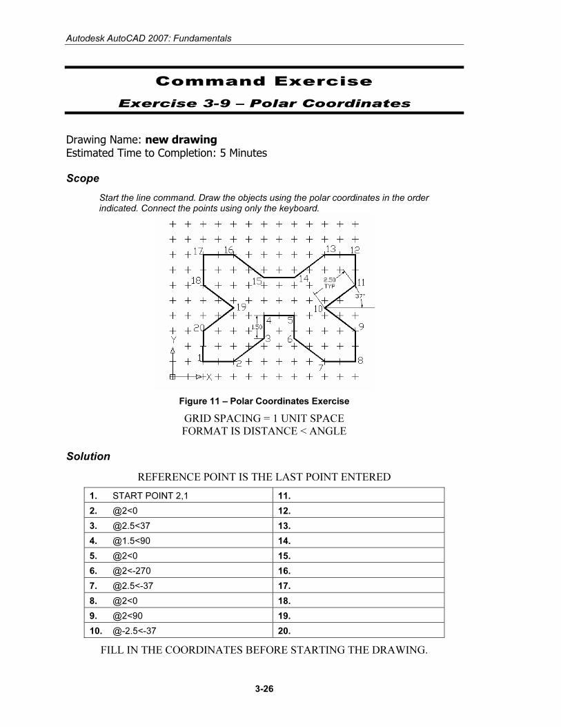
Start the line command. Draw the objects using the polar coordinates in the order indicated. Connect the points using only the keyboard.
Figure 11 – Polar Coordinates Exercise
GRID SPACING = 1 UNIT SPACE FORMAT IS DISTANCE < ANGLE
Solution
REFERENCE POINT IS THE LAST POINT ENTERED
1. START POINT 2,1 11.
2. @2<0 12.
3. @2.5<37 13.
4. @1.5<90 14.
5. @2<0 15.
6. @2<-270 16.
7. @2.5<-37 17.
8. @2<0 18.
9. @2<90 19.
10. @-2.5<-37 20.
FILL IN THE COORDINATES BEFORE STARTING THE DRAWING.
Copyrighted Material
Copyrighted
Material
Copyrighted Material
Copyrighted
Material
Drawing Lines
3-27
Command Exercise
Exercise 3-10 – Drag Method
Drawing Name: entry4.dwg Estimated Time to Completion: 5 Minutes
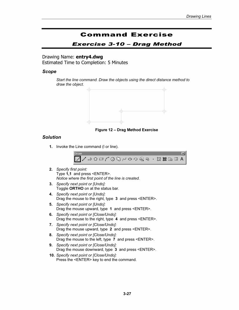
Scope
Start the line command. Draw the objects using the direct distance method to draw the object.
Figure 12 – Drag Method Exercise
Solution
1. Invoke the Line command (l or line).
2. Specify first point: Type 1,1 and press <ENTER>. Notice where the first point of the line is created.
3. Specify next point or [Undo]: Toggle ORTHO on at the status bar.
4. Specify next point or [Undo]: Drag the mouse to the right, type 3 and press <ENTER>.
5. Specify next point or [Undo]: Drag the mouse upward, type 1 and press <ENTER>.
6. Specify next point or [Close/Undo]: Drag the mouse to the right, type 4 and press <ENTER>.
7. Specify next point or [Close/Undo]: Drag the mouse upward, type 2 and press <ENTER>.
8. Specify next point or [Close/Undo]: Drag the mouse to the left, type 7 and press <ENTER>.
9. Specify next point or [Close/Undo]: Drag the mouse downward, type 3 and press <ENTER>.
10. Specify next point or [Close/Undo]: Press the <ENTER> key to end the command.
Copyrighted Material
Copyrighted
Material
Copyrighted Material
Copyrighted
Material
Autodesk AutoCAD 2007: Fundamentals
3-28
Command Exercise
Exercise 3-11 – Drag Method
Drawing Name: new drawing Estimated Time to Completion: 5 Minutes
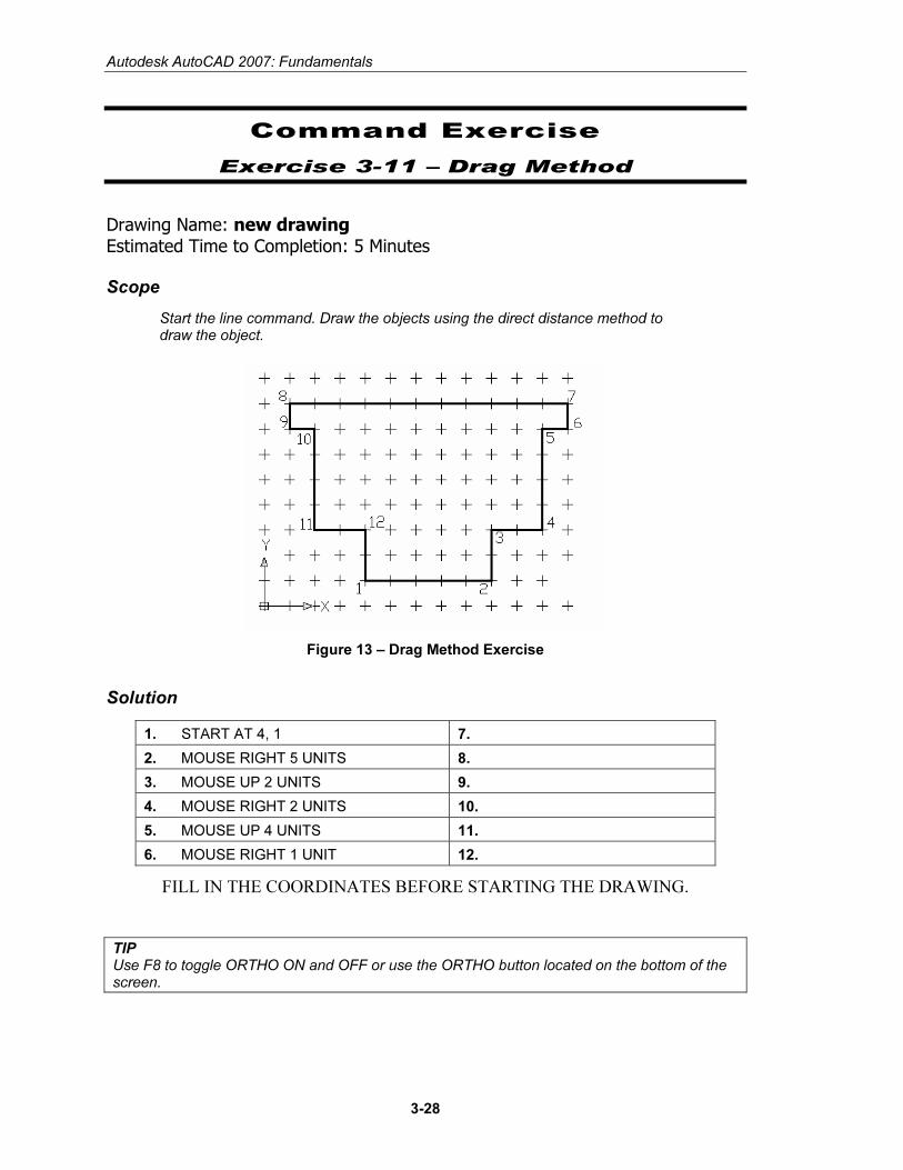
Scope
Start the line command. Draw the objects using the direct distance method to draw the object.
Figure 13 – Drag Method Exercise
Solution
1. START AT 4, 1 7.
2. MOUSE RIGHT 5 UNITS 8.
3. MOUSE UP 2 UNITS 9.
4. MOUSE RIGHT 2 UNITS 10.
5. MOUSE UP 4 UNITS 11.
6. MOUSE RIGHT 1 UNIT 12.
FILL IN THE COORDINATES BEFORE STARTING THE DRAWING.
TIP Use F8 to toggle ORTHO ON and OFF or use the ORTHO button located on the bottom of the screen.
Copyrighted Material
Copyrighted
Material
Copyrighted Material
Copyrighted
Material
Drawing Lines
3-29
Command Exercise
Exercise 3-12 –Mixed Method
Drawing Name: new drawing Estimated Time to Completion: 5 Minutes
Scope
Start the line command. Using the table, create a mystery figure.
Solution
Draw an object by connecting the point coordinates below.
Points Coordinates Points Coordinates
1 2,2 8 @-1.5,0
2 @1.5,0 9 @0,1.25
3 @.75<90 10 @-1.25,1.25
4 @1.5<0 11 @2<180
5 @0,-.75 12 @-1.25,-1.25
6 @3,0 13 @2.25<270
7 @1<90
Extra What was the easiest method?
Copyrighted Material
Copyrighted
Material
Copyrighted Material
Copyrighted
Material
Autodesk AutoCAD 2007: Fundamentals
3-30
EE rr aa ss ee
Command Locator
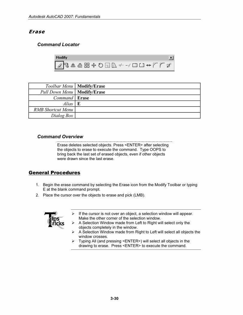
Toolbar Menu Modify/Erase
Pull Down Menu Modify/Erase
Command Erase
Alias E
RMB Shortcut Menu
Dialog Box
Command Overview
Erase deletes selected objects. Press <ENTER> after selecting the objects to erase to execute the command. Type OOPS to bring back the last set of erased objects, even if other objects were drawn since the last erase.
General Procedures
1. Begin the erase command by selecting the Erase icon from the Modify Toolbar or typing E at the blank command prompt.
2. Place the cursor over the objects to erase and pick (LMB).
� If the cursor is not over an object, a selection window will appear. Make the other corner of the selection window.
� A Selection Window made from Left to Right will select only the objects completely in the window.
� A Selection Window made from Right to Left will select all objects the window crosses.
� Typing All (and pressing <ENTER>) will select all objects in the drawing to erase. Press <ENTER> to execute the command.
Copyrighted Material
Copyrighted
Material
Copyrighted Material
Copyrighted
Material
Drawing Lines
3-31
Command Exercise
Exercise 3-13 – Erase
Drawing Name: erase1.dwg Estimated Time to Completion: 5 Minutes
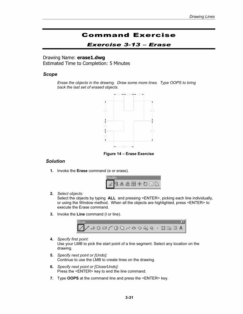
Scope
Erase the objects in the drawing. Draw some more lines. Type OOPS to bring back the last set of erased objects.
Figure 14 – Erase Exercise
Solution
1. Invoke the Erase command (e or erase).
2. Select objects: Select the objects by typing ALL and pressing <ENTER>, picking each line individually, or using the Window method. When all the objects are highlighted, press <ENTER> to execute the Erase command.
3. Invoke the Line command (l or line).
4. Specify first point: Use your LMB to pick the start point of a line segment. Select any location on the drawing.
5. Specify next point or [Undo]: Continue to use the LMB to create lines on the drawing.
6. Specify next point or [Close/Undo]: Press the <ENTER> key to end the line command.
7. Type OOPS at the command line and press the <ENTER> key.
Copyrighted Material
Copyrighted
Material
Copyrighted Material
Copyrighted
Material
Autodesk AutoCAD 2007: Fundamentals
3-32
TIP Select all the objects to erase, then press <ENTER> to execute the command. To remove an object from the selection set, hold down the shift key and select the object again. See that it is removed from the selection set. Then press <ENTER>.
Copyrighted Material
Copyrighted
Material
Copyrighted Material
Copyrighted
Material
Drawing Lines
3-33
Review Questions
1. At the select object prompt, what letter must you type to select using a window?
� W � SO � SP � S
2. Write down the letter to type for each of the following Object Selection options:
Previous ________________________
Last ________________________
Fence ________________________
All ________________________
Crossing Window ________________________
Crossing Polygon ________________________
Window Polygon ________________________
3. When selecting objects by picking in a blank area in the drawing window, what is the difference between the following:
Making a select box from right to left. ________
Making a select box from left to right. ________
4. When using the POLAR method of coordinate entry, which tray button should be enabled?
5. When entering direct coordinates, which tray button should be disabled?
Copyrighted Material
Copyrighted
Material
Copyrighted Material
Copyrighted
Material
Autodesk AutoCAD 2007: Fundamentals
3-34
Review Answers
1. W for window
2. P,L,F,A or enter, CW, CP, CW.
3. WINDOW, CROSSING
4. POLAR
5. DYN
![Autodesk 수동활성화가이드...6] Autodesk AUTODESK Autodesk AutoCAD LT 2017 XC4T LNS4 oc4U 1179 GAW4 OT52 RRGF 8PTZ Autodesk AutoCAD LT 2017 Autodesk. 4 1179 8 wrz 12 GSIS o](https://img.pdfslide.tips/doc/110x75/5e259243f96e6c38222e5f4d/autodesk-eoeeeoe-6-autodesk-autodesk-autodesk-autocad-lt-2017.jpg)
![Curso de Autodesk Autocad® - Cursos de Diseño Gráfico ...Curso de Autodesk Autocad® 2D 30 HRS Autodesk Autocad® 2D Autodesk Autocad® [ Diseño y documentación de planos ] 30](https://img.pdfslide.tips/doc/110x75/60bf32457f62ce72bb78f8cb/curso-de-autodesk-autocad-cursos-de-diseo-grfico-curso-de-autodesk-autocad.jpg)


![AutoCAD 2016 Stand-Alone - 碁峰資訊extdlsvr01.gotop.com.tw/.../QA/Autodesk/2016/AutoCAD_2016_Stand … · 6] AutaCAD@ 2016 AUTODESK AUTOCAD 201 6 Autodesk@ AutoCAD@ 2016 g] Exchange](https://img.pdfslide.tips/doc/110x75/5bb8bfe109d3f2931b8ca0be/autocad-2016-stand-alone-6-autacad-2016-autodesk-autocad-201.jpg)