Embed Size (px)
Citation preview
11
Advance Information Advance Information Systems Development Systems Development
(SD3043)(SD3043)Lecture 2: UML OverviewLecture 2: UML Overview
Dr. Haris MouratidisDr. Haris [email protected]@uel.ac.uk
33thth October 2006 October 2006
22
Last Week’s LectureLast Week’s Lecture
Introduction to the ModuleIntroduction to the Module Description of the ModuleDescription of the Module Teaching & Assessment methodsTeaching & Assessment methods Module ContentModule Content
Overview of Software EngineeringOverview of Software Engineering Definitions of Software EngineeringDefinitions of Software Engineering Concepts Concepts Development ActivitiesDevelopment Activities
33
Learning ObjectivesLearning Objectives
After this lecture you should be able to:After this lecture you should be able to: Understand UML concepts Understand UML concepts Understand UML notationsUnderstand UML notations Use UML to model information systemsUse UML to model information systems
44
Lecture LayoutLecture Layout
NotationNotation An introduction to the Unified Modeling An introduction to the Unified Modeling
Language (UML)Language (UML) An overview of UMLAn overview of UML
Use Case DiagramsUse Case Diagrams Class DiagramsClass Diagrams Interaction diagramsInteraction diagrams Statechart DiagramsStatechart Diagrams Activity DiagramsActivity Diagrams
ConclusionConclusion
55
NotationNotation
According to the “hyper dictionary” According to the “hyper dictionary” notationnotation is is defined as a technical system of symbols used to defined as a technical system of symbols used to represent special thingsrepresent special things
Notation enable us to articulate complex ideas Notation enable us to articulate complex ideas preciselyprecisely In large projects accuracy and clarity are vitalIn large projects accuracy and clarity are vital
A notation should A notation should Have well defined semanticsHave well defined semantics Be well suited for representing a given aspect of a systemBe well suited for representing a given aspect of a system Be well understood among project participantsBe well understood among project participants
66
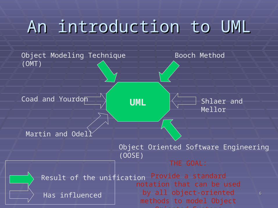
An introduction to UMLAn introduction to UML
Object Modeling Technique (OMT) Booch Method
Object Oriented Software Engineering (OOSE)
Coad and Yourdon
Martin and Odell
UML Shlaer and Mellor
Result of the unification
Has influenced
THE GOAL:
Provide a standard notation that can be used by all object-oriented methods to model Object Oriented
Systems
77
An introduction to UML (II)An introduction to UML (II)
UML has been designed for a broad range UML has been designed for a broad range of applicationsof applications
Introduce only five diagramsIntroduce only five diagrams Use Case DiagramsUse Case Diagrams Class DiagramsClass Diagrams Interaction DiagramsInteraction Diagrams Statechart DiagramsStatechart Diagrams Activity DiagramsActivity Diagrams
88
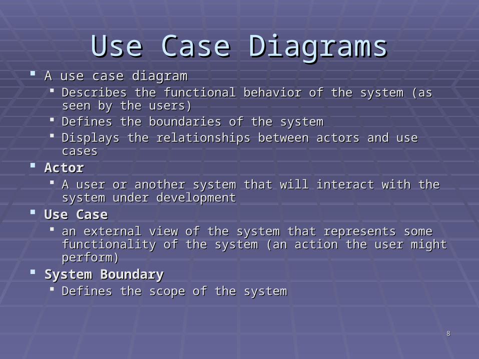
Use Case DiagramsUse Case Diagrams A use case diagram A use case diagram
Describes the functional behavior of the system (as seen by Describes the functional behavior of the system (as seen by the users)the users)
Defines the boundaries of the systemDefines the boundaries of the system Displays the relationships between actors and use casesDisplays the relationships between actors and use cases
ActorActor A user or another system that will interact with the system A user or another system that will interact with the system
under development under development Use CaseUse Case
an external view of the system that represents some an external view of the system that represents some functionality of the system (an action the user might perform)functionality of the system (an action the user might perform)
System BoundarySystem Boundary Defines the scope of the systemDefines the scope of the system
99
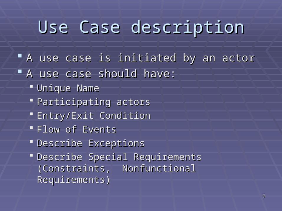
Use Case descriptionUse Case description
A use case is initiated by an actorA use case is initiated by an actor A use case should have:A use case should have:
Unique Name Unique Name Participating actorsParticipating actors Entry/Exit Condition Entry/Exit Condition Flow of Events Flow of Events Describe ExceptionsDescribe Exceptions Describe Special Requirements (Constraints, Describe Special Requirements (Constraints,
Nonfunctional Requirements)Nonfunctional Requirements)
1010
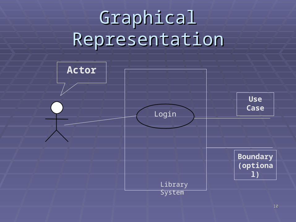
Graphical RepresentationGraphical Representation
Login
Actor
Use Case
Boundary(optional)
Library System
1111
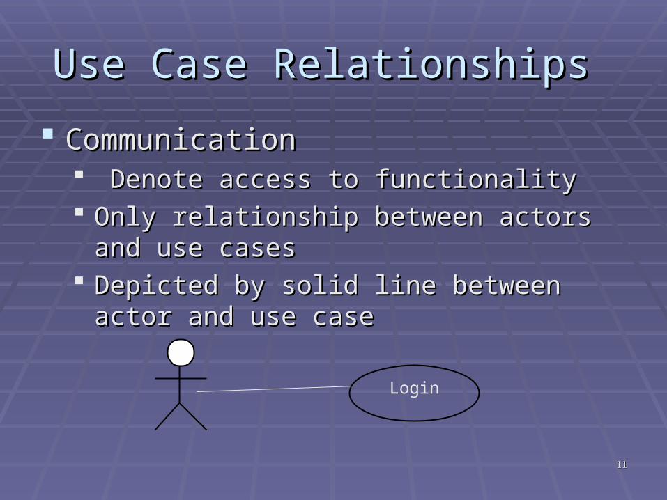
Use Case Relationships Use Case Relationships
CommunicationCommunication Denote access to functionalityDenote access to functionality Only relationship between actors and use Only relationship between actors and use
casescases Depicted by solid line between actor and use Depicted by solid line between actor and use
casecase
Login
1212
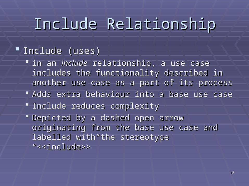
Include RelationshipInclude Relationship
Include (uses)Include (uses) in an in an includeinclude relationship, a use case includes relationship, a use case includes
the functionality described in another use the functionality described in another use case as a part of its processcase as a part of its process
Adds extra behaviour into a base use case Adds extra behaviour into a base use case Include reduces complexity Include reduces complexity Depicted by a dashed open arrow originating Depicted by a dashed open arrow originating
from the base use case and labelled with the from the base use case and labelled with the stereotype “<<include>>”stereotype “<<include>>”
1313
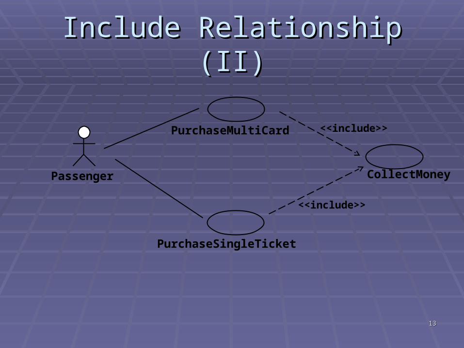
Include Relationship (II)Include Relationship (II)
Passenger
PurchaseMultiCard
PurchaseSingleTicket
CollectMoney
<<include>>
<<include>>
1414
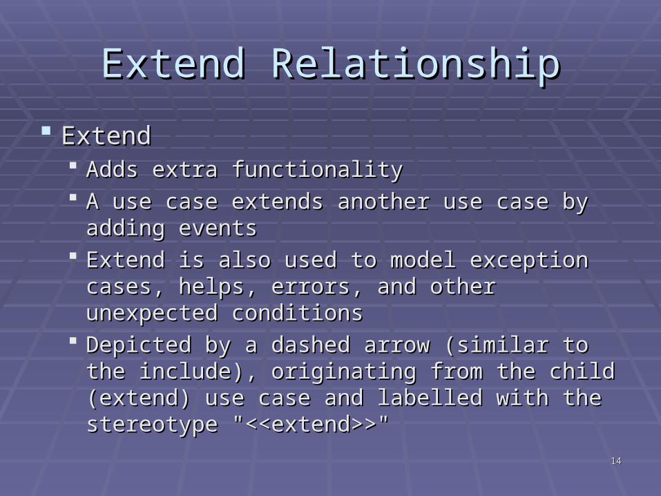
Extend RelationshipExtend Relationship
ExtendExtend Adds extra functionalityAdds extra functionality A use case extends another use case by adding A use case extends another use case by adding
eventsevents Extend is also used to model exception cases, Extend is also used to model exception cases,
helps, errors, and other unexpected conditionshelps, errors, and other unexpected conditions Depicted by a dashed arrow (similar to the Depicted by a dashed arrow (similar to the
include), originating from the child (extend) use include), originating from the child (extend) use case and labelled with the stereotype case and labelled with the stereotype "<<extend>>""<<extend>>"
1515
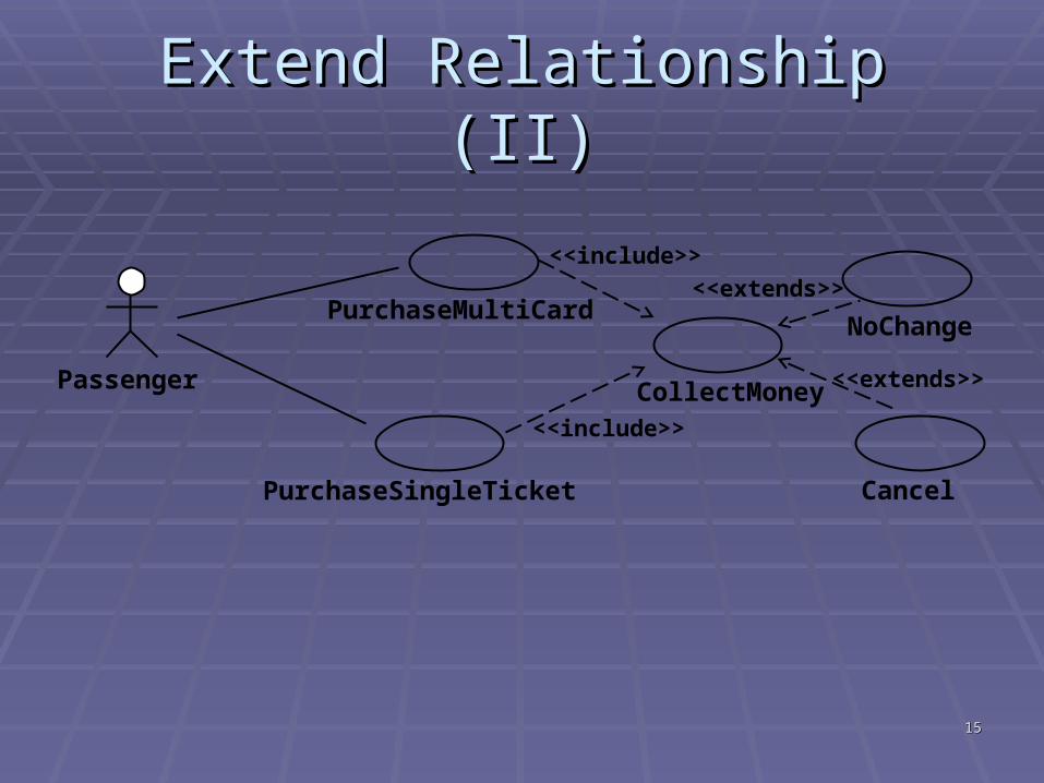
Extend Relationship (II)Extend Relationship (II)
Passenger
PurchaseMultiCard
PurchaseSingleTicket
CollectMoney
<<include>>
<<include>>
Cancel
<<extends>>
NoChange
<<extends>>
1616
Use Case diagram testing Use Case diagram testing questionsquestions
Is our notation correct?Is our notation correct? Are all actors identified? Are all actors identified? Can the system described actually be built? Can the system described actually be built? Are all the system's functional requirements Are all the system's functional requirements
reflected in the use cases? reflected in the use cases? Do the use cases define all the functionality within Do the use cases define all the functionality within
the scope of the system and nothing outside the the scope of the system and nothing outside the scope? scope?
Can we trace each use case back to its Can we trace each use case back to its requirements? requirements?
1717
Use Case diagram guidelinesUse Case diagram guidelines Do have a clear idea of the system you intend to Do have a clear idea of the system you intend to
describedescribe Do ensure all use cases provide value to at least one Do ensure all use cases provide value to at least one
actoractor Do involve a “user” in the writing process. It is users’ Do involve a “user” in the writing process. It is users’
requirementsrequirements Do not believe anyone telling you use case Do not believe anyone telling you use case
modelling is simple…It is not!!!modelling is simple…It is not!!! Do not include system design elements in the use Do not include system design elements in the use
casescases Do not get worked up about <<extend>>, Do not get worked up about <<extend>>,
<<include>>!<<include>>! Do not forget actors representing other systems!Do not forget actors representing other systems!
1818
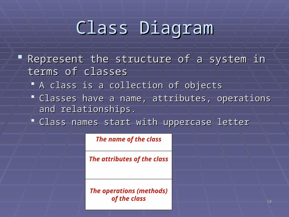
Class DiagramClass Diagram
Represent the structure of a system in terms of Represent the structure of a system in terms of classesclasses A class is a collection of objectsA class is a collection of objects Classes have a name, attributes, operations and Classes have a name, attributes, operations and
relationships.relationships. Class names start with uppercase letterClass names start with uppercase letter
The name of the class
The attributes of the class
The operations (methods) of the class
1919
Developing a class diagramDeveloping a class diagram
Not right or wrong techniqueNot right or wrong technique One techniqueOne technique
Pick all the nouns (person, place, thing) and Pick all the nouns (person, place, thing) and noun phrases from the requirements noun phrases from the requirements
Discard any inappropriate candidatesDiscard any inappropriate candidates Redundant, event, operation, attribute, outside the Redundant, event, operation, attribute, outside the
scope of the systemscope of the system
Practice!Practice!
2020
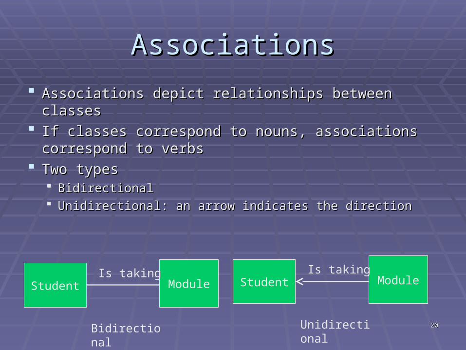
AssociationsAssociations
Associations depict relationships between classesAssociations depict relationships between classes If classes correspond to nouns, associations If classes correspond to nouns, associations
correspond to verbscorrespond to verbs Two typesTwo types
BidirectionalBidirectional Unidirectional: an arrow indicates the directionUnidirectional: an arrow indicates the direction
Student ModuleIs taking
Student ModuleIs taking
Bidirectional Unidirectional
2121
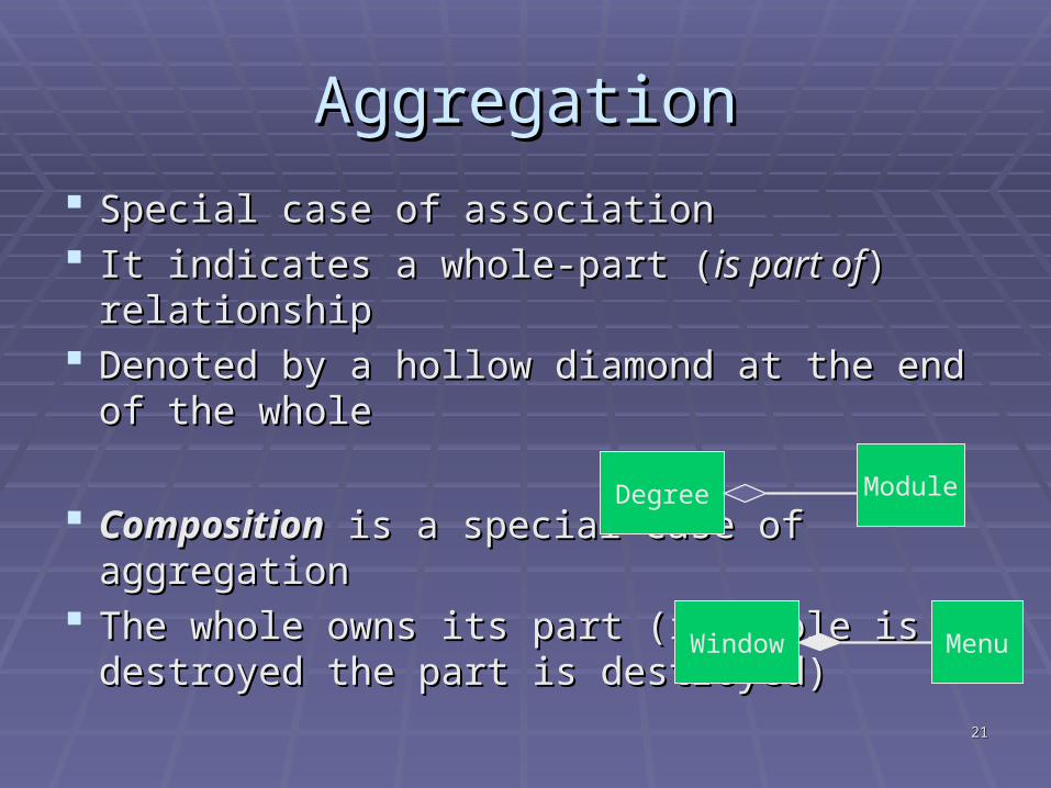
AggregationAggregation
Special case of associationSpecial case of association It indicates a whole-part (It indicates a whole-part ( is part ofis part of) relationship) relationship Denoted by a hollow diamond at the end of the Denoted by a hollow diamond at the end of the
wholewhole
CompositionComposition is a special case of aggregation is a special case of aggregation The whole owns its part (if whole is destroyed The whole owns its part (if whole is destroyed
the part is destroyed)the part is destroyed)
Degree Module
Window Menu
2222
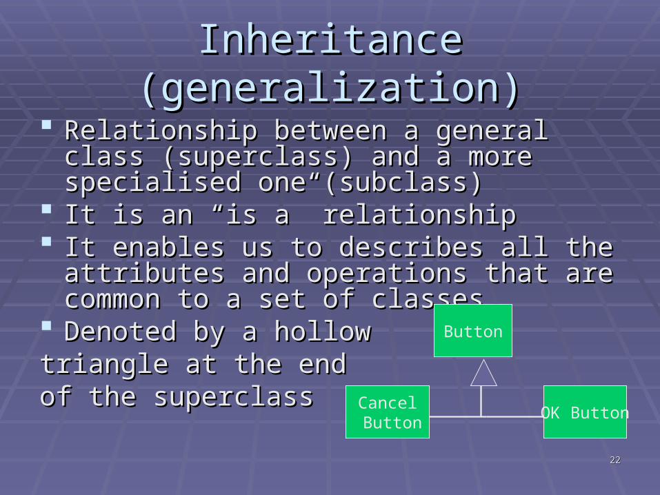
Inheritance (generalization)Inheritance (generalization)
Relationship between a general class Relationship between a general class (superclass) and a more specialised one (superclass) and a more specialised one (subclass)(subclass)
It is an “is a” relationshipIt is an “is a” relationship It enables us to describes all the attributes It enables us to describes all the attributes
and operations that are common to a set of and operations that are common to a set of classesclasses
Denoted by a hollow Denoted by a hollow triangle at the end triangle at the end of the superclass of the superclass
Button
OK ButtonCancel Button
2323
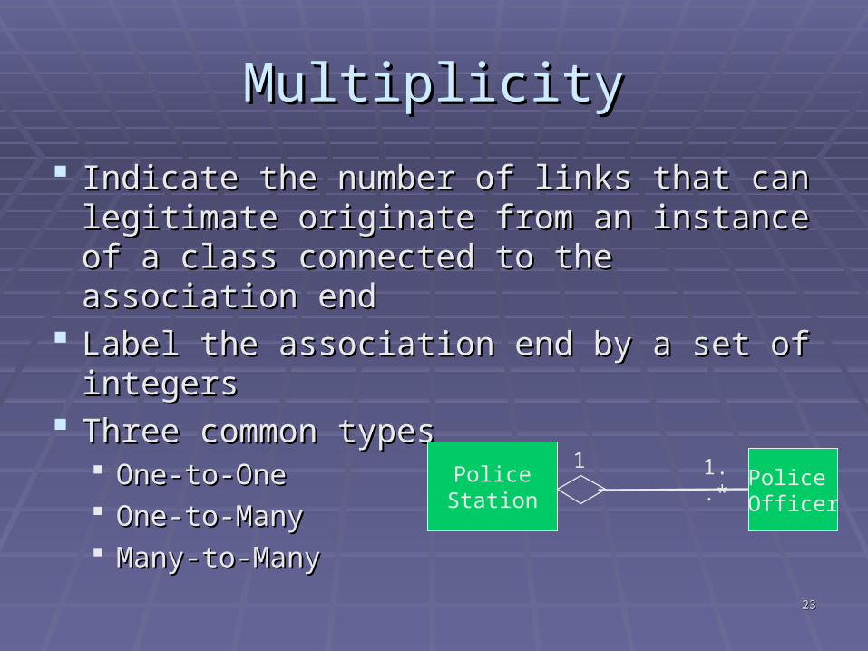
MultiplicityMultiplicity
Indicate the number of links that can Indicate the number of links that can legitimate originate from an instance of a legitimate originate from an instance of a class connected to the association endclass connected to the association end
Label the association end by a set of integersLabel the association end by a set of integers Three common typesThree common types
One-to-OneOne-to-One One-to-ManyOne-to-Many Many-to-ManyMany-to-Many
PoliceStation
Police Officer
1 1..*
2424
Class Diagram testing questionsClass Diagram testing questions
Does each class define attributes, Does each class define attributes, methods, relationships, and multiplicity? methods, relationships, and multiplicity?
Is each association well named? Is each association well named? Is each association’s and aggregation’s Is each association’s and aggregation’s
multiplicity correct?multiplicity correct? Is each class named with a strong noun? Is each class named with a strong noun? Have all redundant, irrelevant, or vague Have all redundant, irrelevant, or vague
classes been removed from the diagram? classes been removed from the diagram?
2525
Class diagram guidelinesClass diagram guidelines Use singular names because each class represents Use singular names because each class represents
a generalised version of a singular objecta generalised version of a singular object Use simple class names (Student instead of …Use simple class names (Student instead of …
PersonWhoStudies)PersonWhoStudies) Do not model actors in class diagramsDo not model actors in class diagrams Use full names for attributes Use full names for attributes Make sure you class diagram is consistent with the Make sure you class diagram is consistent with the
requirementsrequirements Try to avoid using only * for multiplicity (Is it 0..* or Try to avoid using only * for multiplicity (Is it 0..* or
1..*)1..*)
2626
Quiz time!!!Quiz time!!!
Consider an ATM System. Which of the Consider an ATM System. Which of the following is NOT an actor.following is NOT an actor.A.A. CustomerCustomer
B.B. Central Bank computerCentral Bank computer
C.C. ATM processorATM processor
D.D. ThiefThief
2727
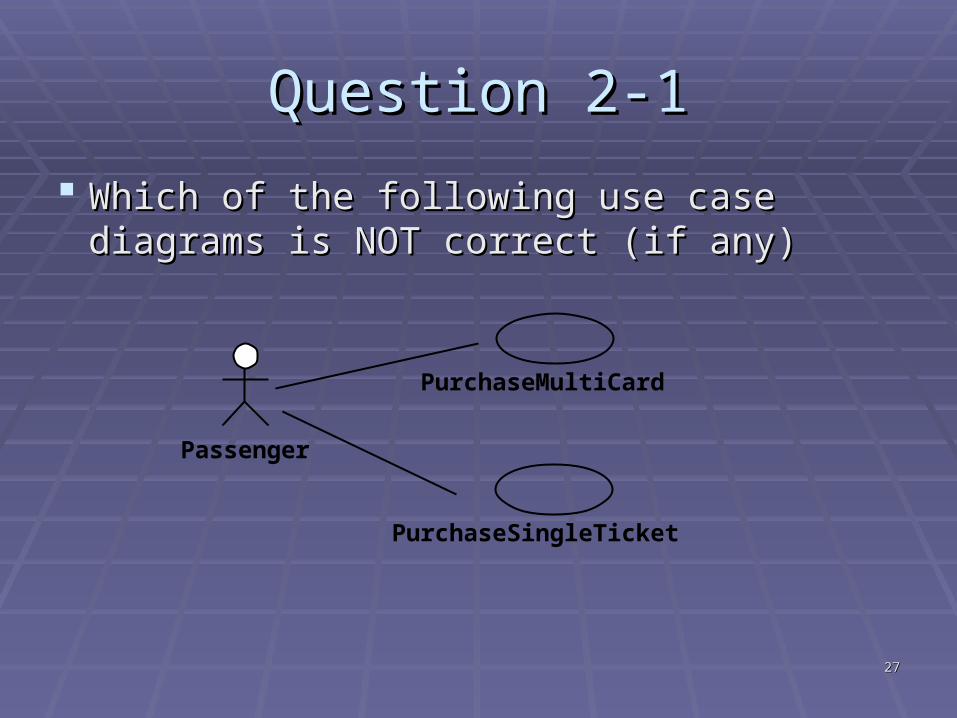
Question 2-1Question 2-1
Which of the following use case diagrams is Which of the following use case diagrams is NOT correct (if any)NOT correct (if any)
Passenger
PurchaseMultiCard
PurchaseSingleTicket
2828
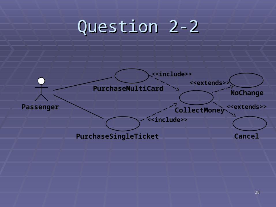
Question 2-2Question 2-2
Passenger
PurchaseMultiCard
PurchaseSingleTicket
CollectMoney
<<include>>
<<include>>
Cancel
<<extends>>
NoChange
<<extends>>
2929
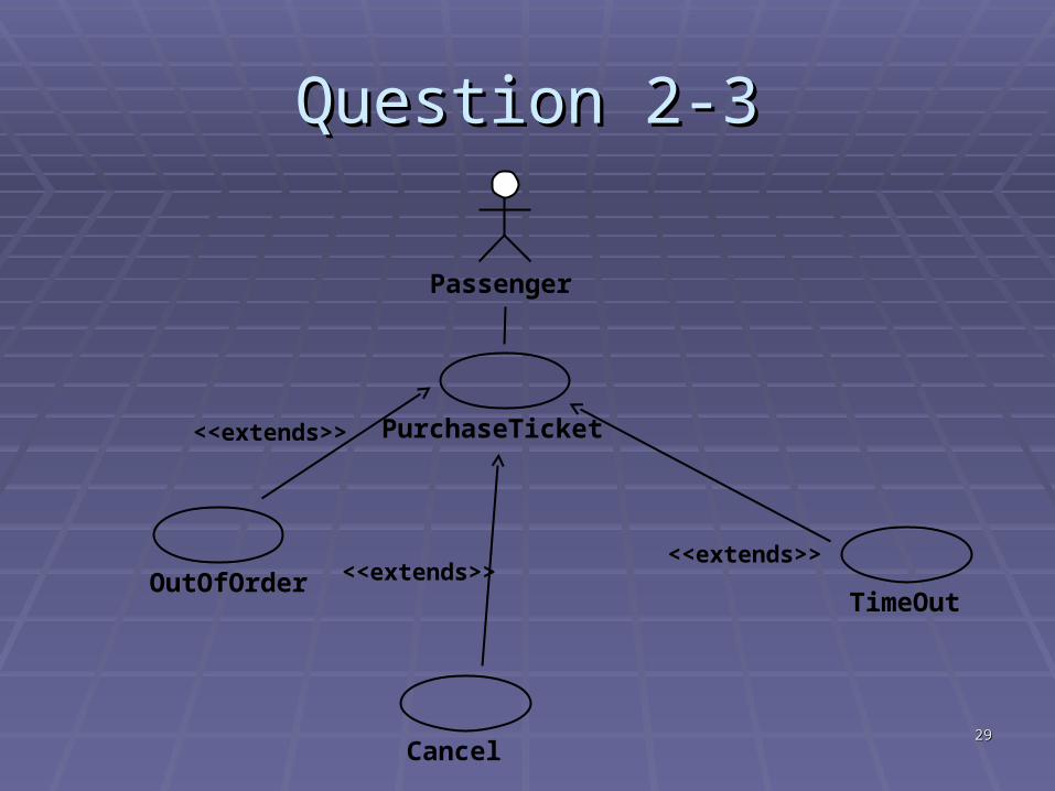
Question 2-3Question 2-3
Passenger
PurchaseTicket
OutOfOrder
<<extends>>
Cancel
<<extends>>TimeOut
<<extends>>
3030
Interaction diagramsInteraction diagrams Used to describe Used to describe communicationcommunication between between
interacting objects (and actors)interacting objects (and actors) Communication takes place through Communication takes place through
messagesmessages Interaction diagrams should be used when Interaction diagrams should be used when
you want to look at the behaviour of several you want to look at the behaviour of several objects within a single use case.objects within a single use case.
3131
Interaction Diagrams (II)Interaction Diagrams (II)
Two typesTwo types SequenceSequence: focus on the order that : focus on the order that
messages sent messages sent CollaborationCollaboration: focus on the relationship : focus on the relationship
between the objectsbetween the objects
3232
Sequence diagramsSequence diagrams
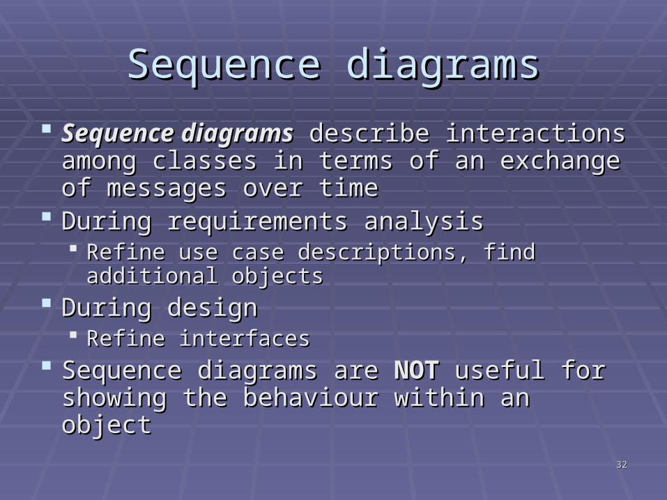
Sequence diagramsSequence diagrams describe interactions describe interactions among classes in terms of an exchange of among classes in terms of an exchange of messages over time messages over time
During requirements analysisDuring requirements analysis Refine use case descriptions, find additional Refine use case descriptions, find additional
objectsobjects During designDuring design
Refine interfacesRefine interfaces Sequence diagrams are Sequence diagrams are NOTNOT useful for useful for
showing the behaviour within an object showing the behaviour within an object
3333
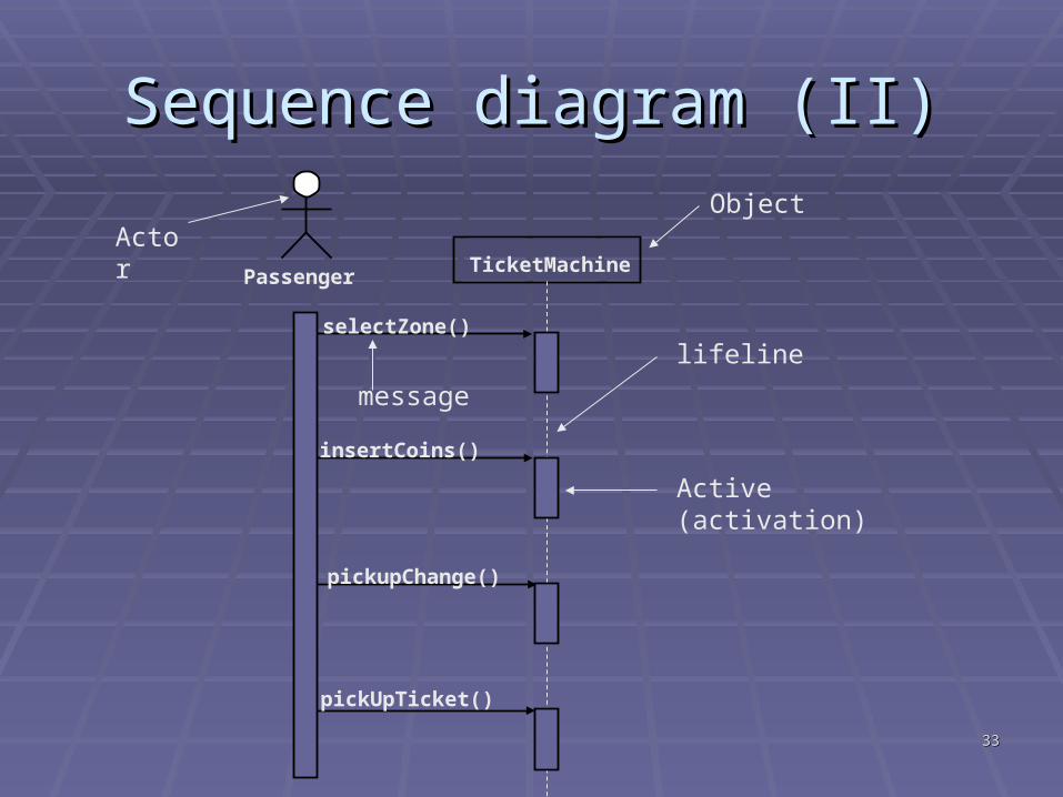
Sequence diagram (II)Sequence diagram (II)
selectZone()
pickupChange()
pickUpTicket()
insertCoins()
PassengerTicketMachine
ActorObject
lifeline
message
Active (activation)
3434
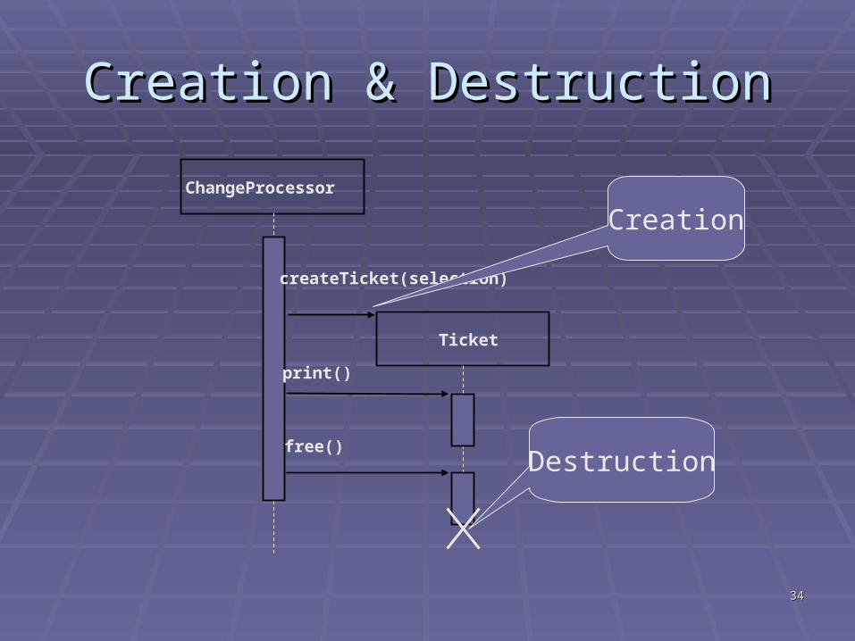
Creation & DestructionCreation & Destruction
ChangeProcessor
Ticket
createTicket(selection)
free()
Creation
Destruction
print()
3535
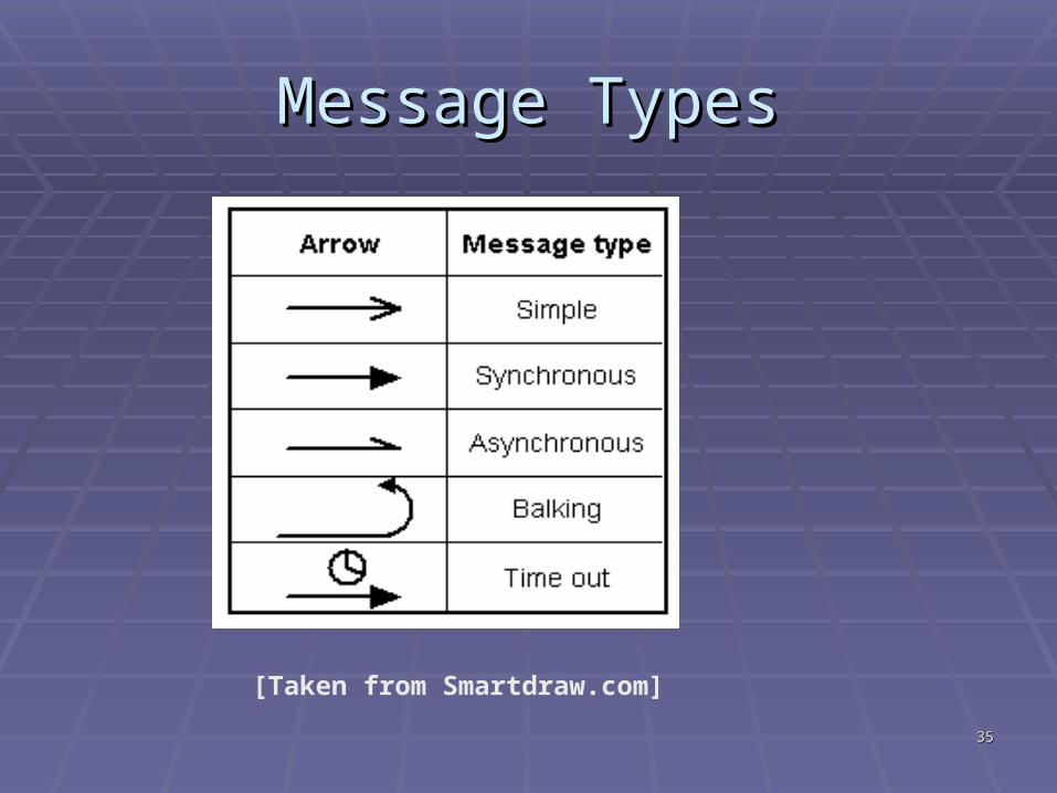
Message TypesMessage Types
[Taken from Smartdraw.com]
3636
Sequence diagram testing questionsSequence diagram testing questions Does each object required for the interaction appear Does each object required for the interaction appear
on the diagram? on the diagram? Have all objects not required in the interaction been Have all objects not required in the interaction been
removed from the diagram? removed from the diagram? Does each object’s lifeline begin and end at the Does each object’s lifeline begin and end at the
proper time? proper time? Is each object’s activation described properly? Is each object’s activation described properly? If the object’s lifetime terminates, is it indicated with If the object’s lifetime terminates, is it indicated with
an X? an X? Is each use case represented by at least one Is each use case represented by at least one
sequence diagram? sequence diagram? Does each actor appear on at least one sequence Does each actor appear on at least one sequence
diagram? diagram?
3737
Sequence diagram guidelines Sequence diagram guidelines Start the message flow of a sequence diagram in the Start the message flow of a sequence diagram in the
top-left cornertop-left corner Have in mind that a message that appears lower in the Have in mind that a message that appears lower in the
diagram is sent after one that appears above itdiagram is sent after one that appears above it Arrange your actors, classes across the top of the Arrange your actors, classes across the top of the
diagram in such a way as to depict message flow from diagram in such a way as to depict message flow from left to rightleft to right
Make sure the actors that appear on the sequence Make sure the actors that appear on the sequence diagrams have the same name as on the use case diagrams have the same name as on the use case diagramsdiagrams
3838
Sequence Diagram guidelines (II)Sequence Diagram guidelines (II)
Have in mind that an actor CAN have the Have in mind that an actor CAN have the same name as a classsame name as a class
Include a description of the logic you are Include a description of the logic you are modellingmodelling
Model proactive (activate the sequence) Model proactive (activate the sequence) actors, classes on the left-hand side of the actors, classes on the left-hand side of the diagramdiagram
Model reactive (system initiates interaction Model reactive (system initiates interaction with) actors on the right-hand side of the with) actors on the right-hand side of the diagramdiagram
3939
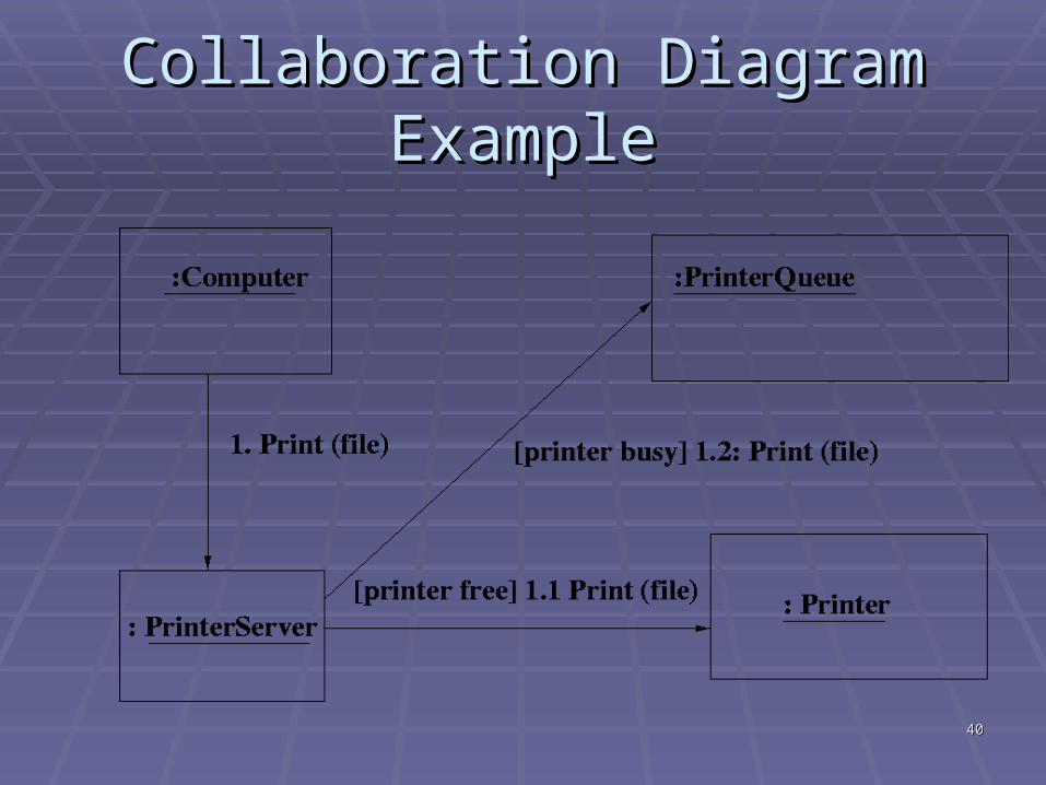
Collaboration diagramsCollaboration diagrams
Depict the same information as sequence Depict the same information as sequence diagramsdiagrams
It shows the objects and their association It shows the objects and their association with other objects in the system apart from with other objects in the system apart from how they interact with each other. how they interact with each other.
Represent the sequence of messages by Represent the sequence of messages by numbering the interactionsnumbering the interactions+More compact diagramMore compact diagram- More difficult to followMore difficult to follow
4040
Collaboration Diagram ExampleCollaboration Diagram Example
4141
Statechart diagramsStatechart diagrams
Useful for describing the behaviour of Useful for describing the behaviour of individual objects over the full set of use individual objects over the full set of use cases that affect those objects cases that affect those objects
Statechart diagrams describeStatechart diagrams describe All of the states that an object can have, All of the states that an object can have, The events under which an object changes state The events under which an object changes state
(transitions), (transitions), The conditions that must be fulfilled before the The conditions that must be fulfilled before the
transition will occur (guards), transition will occur (guards), The activities undertaken during the life of an The activities undertaken during the life of an
object (actions).object (actions).
4242
Elements of StatechartsElements of Statecharts Initial stateInitial state
The object’s initial stateThe object’s initial state StatesStates
A condition during the life of an object in which it satisfies some A condition during the life of an object in which it satisfies some condition, performs some action, or waits for some eventcondition, performs some action, or waits for some event
TransitionsTransitions The change of state within an object The change of state within an object
EventsEvents An occurrence (signal from outside the system, invocation from inside An occurrence (signal from outside the system, invocation from inside
the system, passage of designated period of time) that may trigger a the system, passage of designated period of time) that may trigger a state transition. state transition.
ActionAction One or more actions taken by an object in response to a state change One or more actions taken by an object in response to a state change
GuardGuard A Boolean expression which, if true, enables an event to cause a A Boolean expression which, if true, enables an event to cause a
transitiontransition Final stateFinal state
The object’s final stateThe object’s final state
4343
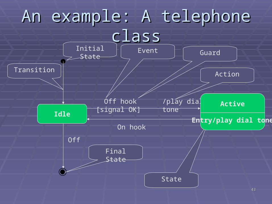
An example: A telephone classAn example: A telephone class
Idle Active
Initial State
State
Transition
/play dial tone
Event Guard
Action
On hook
Off
Final State
Off hook [signal OK] Active
Entry/play dial tone
4444
Statechart diagram testing Statechart diagram testing questionsquestions
Does each state-transition diagram have one Does each state-transition diagram have one and only one initial state? and only one initial state?
Does each state have at least one exit Does each state have at least one exit transition? transition?
If multiple guards exist for a single event, are If multiple guards exist for a single event, are the guards mutually exclusive? the guards mutually exclusive?
Is each state and transition clearly named? Is each state and transition clearly named? Are all of the required states, events, guards, Are all of the required states, events, guards,
transitions, and actions shown on the transitions, and actions shown on the diagram? diagram?
4545
Statechart diagrams guidelinesStatechart diagrams guidelines
Make sure that each statechart diagram Make sure that each statechart diagram refers to only one class!refers to only one class!
You do not have to develop a statechart You do not have to develop a statechart diagram for every class (unless you told diagram for every class (unless you told so)so)
All statechart diagrams should have an All statechart diagrams should have an initial state (the state the class is when it is initial state (the state the class is when it is created)created)
4646
Activity DiagramsActivity Diagrams Activity diagrams describe the workflow behaviour of a Activity diagrams describe the workflow behaviour of a
system system An Activity diagram is a dynamic diagram that shows the An Activity diagram is a dynamic diagram that shows the
activity and the event that causes the object to be in the activity and the event that causes the object to be in the particular state particular state
However, activity diagrams should not take the place However, activity diagrams should not take the place of interaction diagrams and state chart diagrams. Activity of interaction diagrams and state chart diagrams. Activity diagrams do not give detail about how objects behave or diagrams do not give detail about how objects behave or how objects collaborate how objects collaborate
A State diagram shows the different states an object is in A State diagram shows the different states an object is in during the lifecycle of its existence in the system, and the during the lifecycle of its existence in the system, and the transitions in the states of the objects. These transitions transitions in the states of the objects. These transitions depict the activities causing these transitions, shown by depict the activities causing these transitions, shown by arrowsarrows
An Activity diagram talks more about these transitions and An Activity diagram talks more about these transitions and activities causing the changes in the object states activities causing the changes in the object states
4747
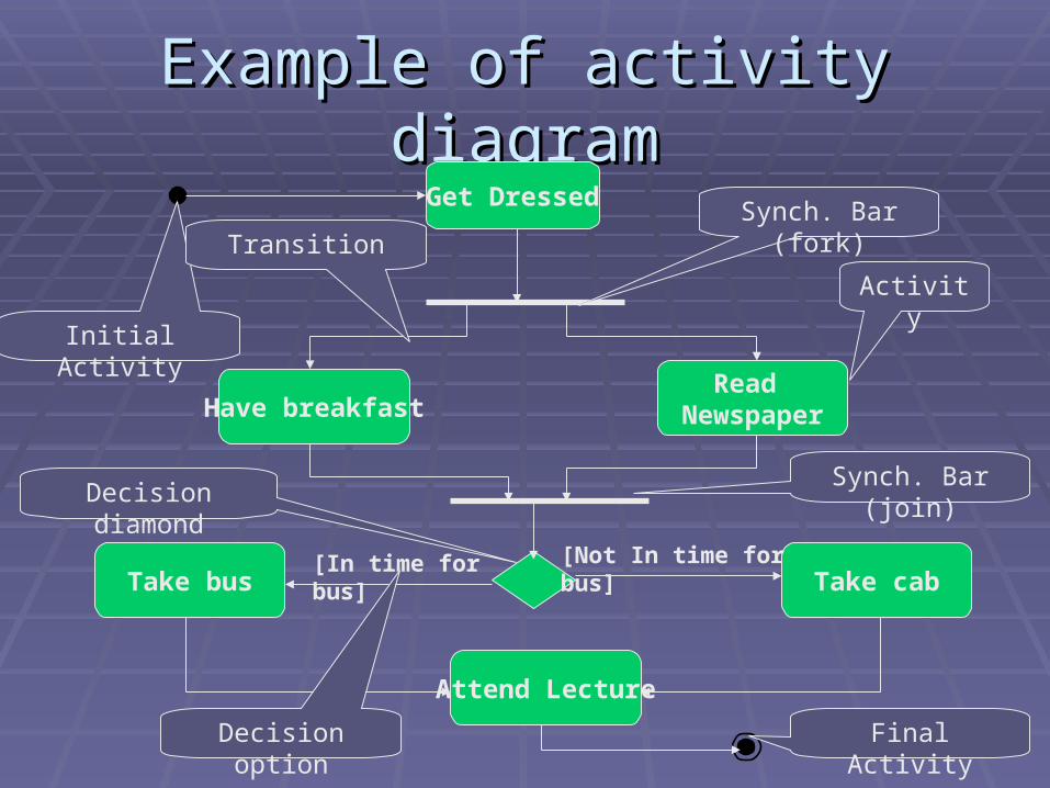
Activity Diagram ElementsActivity Diagram Elements
Initial ActivityInitial Activity The initial activity of the workflowThe initial activity of the workflow
ActivityActivity A state of doing something.A state of doing something.
TransitionTransition Progression to the next activityProgression to the next activity
Synchronisation bar (fork or join)Synchronisation bar (fork or join) Describes concurrent activitiesDescribes concurrent activities
Decision diamond Decision diamond Indicates decisions and the available optionsIndicates decisions and the available options
Final ActivityFinal Activity The final activity of the workflowThe final activity of the workflow
4848
Example of activity diagramExample of activity diagram
Take bus Take cab
Attend Lecture
Get Dressed
Read NewspaperHave breakfast
[In time for bus] [Not In time for bus]
Activity
Synch. Bar (fork)
Synch. Bar (join)Decision diamond
Decision option
Initial Activity
Final Activity
Transition
4949
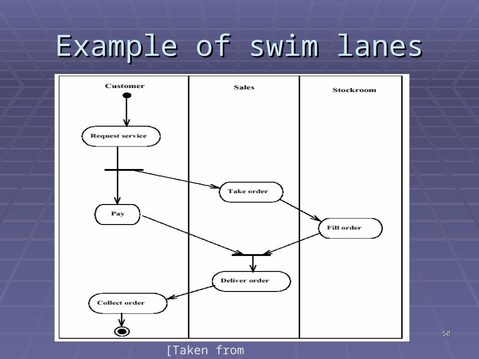
Swim lanesSwim lanes
Enable developers to indicate which actor Enable developers to indicate which actor performs which activityperforms which activity
The diagram is partitioned in such a way The diagram is partitioned in such a way that we can indicate who/what is that we can indicate who/what is performing the activity performing the activity
Partitions called “swim lanes”Partitions called “swim lanes”+Useful because they provide more informationUseful because they provide more information- The diagram becomes largerThe diagram becomes larger
5050
Example of swim lanesExample of swim lanes
[Taken from prestwood.com]
5151
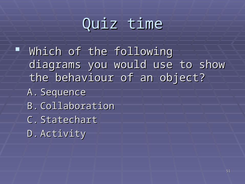
Quiz timeQuiz time
Which of the following diagrams you Which of the following diagrams you would use to show the behaviour of an would use to show the behaviour of an object?object?A.A. SequenceSequence
B.B. CollaborationCollaboration
C.C. StatechartStatechart
D.D. ActivityActivity
5252
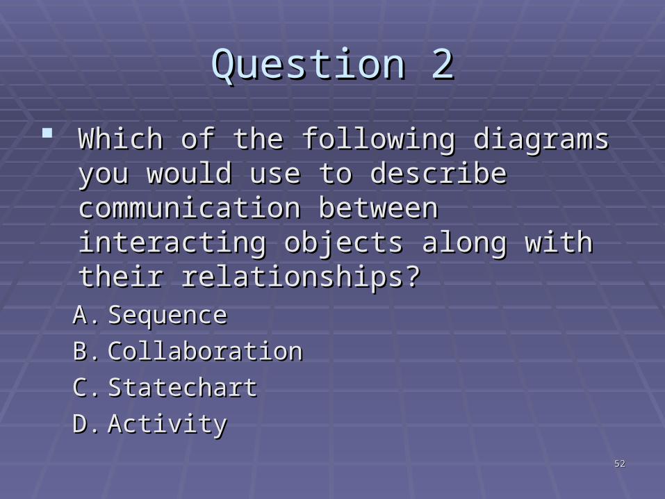
Question 2Question 2
Which of the following diagrams you Which of the following diagrams you would use to describe communication would use to describe communication between interacting objects along with between interacting objects along with their relationships?their relationships?A.A. Sequence Sequence
B.B. CollaborationCollaboration
C.C. StatechartStatechart
D.D. ActivityActivity
5353
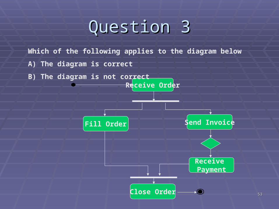
Question 3Question 3
Receive Payment
Close Order
Receive Order
Send InvoiceFill Order
Which of the following applies to the diagram below
A) The diagram is correct
B) The diagram is not correct
5454
ConclusionConclusion
NotationNotation An introduction to the Unified Modeling An introduction to the Unified Modeling
Language (UML)Language (UML) An overview of UMLAn overview of UML Reading list: Chapter 2 (essential), any Reading list: Chapter 2 (essential), any
book about UMLbook about UML Next week: Requirements Elicitation and Next week: Requirements Elicitation and
AnalysisAnalysis
5555
AnnouncementsAnnouncements
Problem with WebCT you can find info on Problem with WebCT you can find info on http://homepages.uel.ac.uk/H.Mouratidis/Shttp://homepages.uel.ac.uk/H.Mouratidis/SD3043D3043
If you haven’t got a handbook get one If you haven’t got a handbook get one from Godfried or download one from the from Godfried or download one from the above linkabove link
Pick up your assignmentPick up your assignment Practicals only some weeksPracticals only some weeks