Embed Size (px)
Citation preview
1
Cryostat assembly, integration and commissioning procedures
M.Olcese
Version: 07 May 2008
2
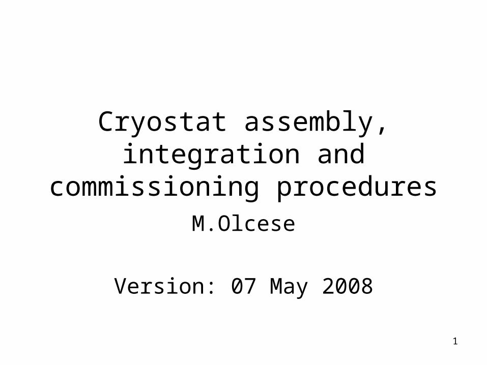
Definitions
• Flanges/plates (from innermost):– MC plate: mixing chamber plate– HEX plate: heat exchanger plate– STILL plate– 4K flange: Inner Vacuum Chamber (IVC) plate– 40K plate– 300K flange: Outer Vacuum Chamber (OVC) plate
• Vessels/screens:– MC screen (upper and lower part)– HEX screen– 4K vessel: IVC vessel– 40K screen– 300K vessel: OVC vessel
3
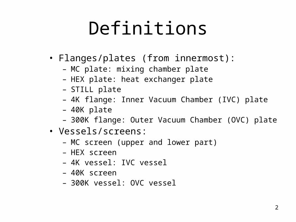
Schematic: cryostat
Main external shielding
300K, 4K vessels and 40K screen
300K, 4K flangesand 40K plate
Lateral STILL lead shield
Internal screens (STILL-HEX-MC)
Lateral STILL lead shield support cradle
Detector
Detector support plate
Internal top lead shield
STILL plate
STILL top lead ring
HEX and MC plates
4
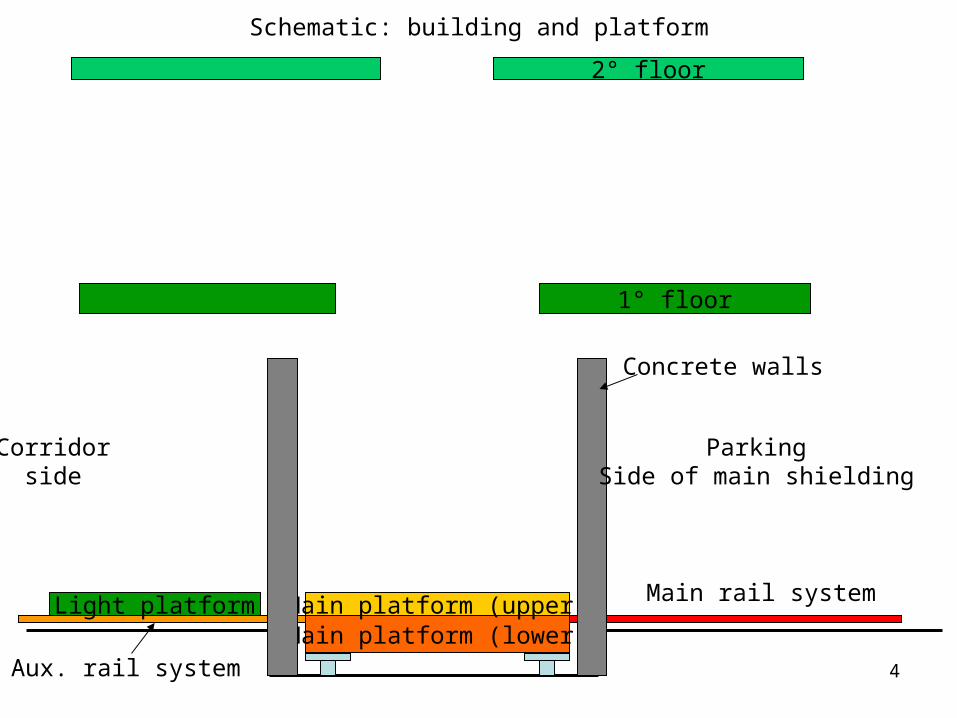
Main platform (lower)
1° floor
Main platform (upper)
2° floor
Light platform
Corridorside
ParkingSide of main shielding
Concrete walls
Main rail system
Aux. rail system
Schematic: building and platform
5
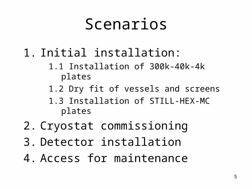
Scenarios
1. Initial installation:1.1 Installation of 300k-40k-4k plates
1.2 Dry fit of vessels and screens
1.3 Installation of STILL-HEX-MC plates
2. Cryostat commissioning
3. Detector installation
4. Access for maintenance
6
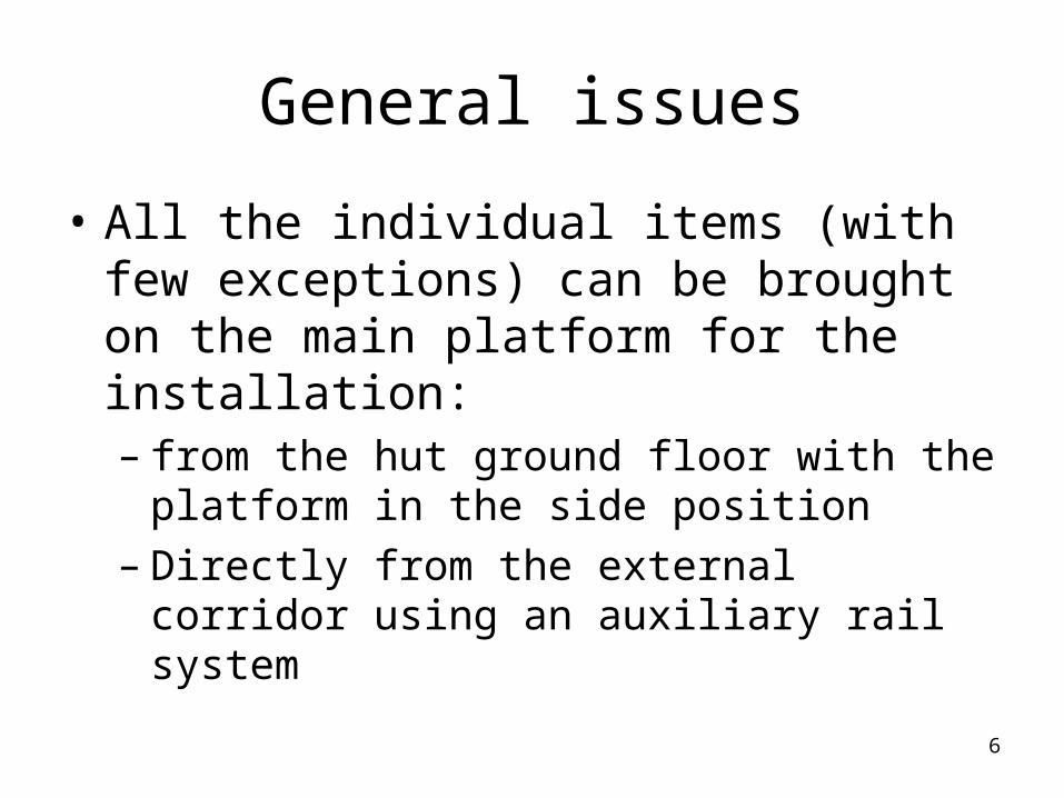
General issues
• All the individual items (with few exceptions) can be brought on the main platform for the installation:– from the hut ground floor with the platform in
the side position– Directly from the external corridor using an
auxiliary rail system
7
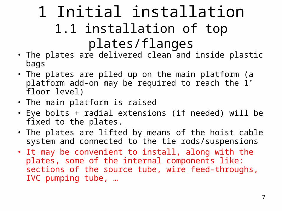
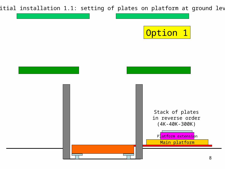
1 Initial installation1.1 installation of top plates/flanges
• The plates are delivered clean and inside plastic bags• The plates are piled up on the main platform (a platform
add-on may be required to reach the 1° floor level)• The main platform is raised• Eye bolts + radial extensions (if needed) will be fixed to
the plates.• The plates are lifted by means of the hoist cable system
and connected to the tie rods/suspensions• It may be convenient to install, along with the plates,
some of the internal components like: sections of the source tube, wire feed-throughs, IVC pumping tube, …
8
Main platform
Platform extension
Option 1
Stack of plates in reverse order (4K-40K-300K)
Initial installation 1.1: setting of plates on platform at ground level
9
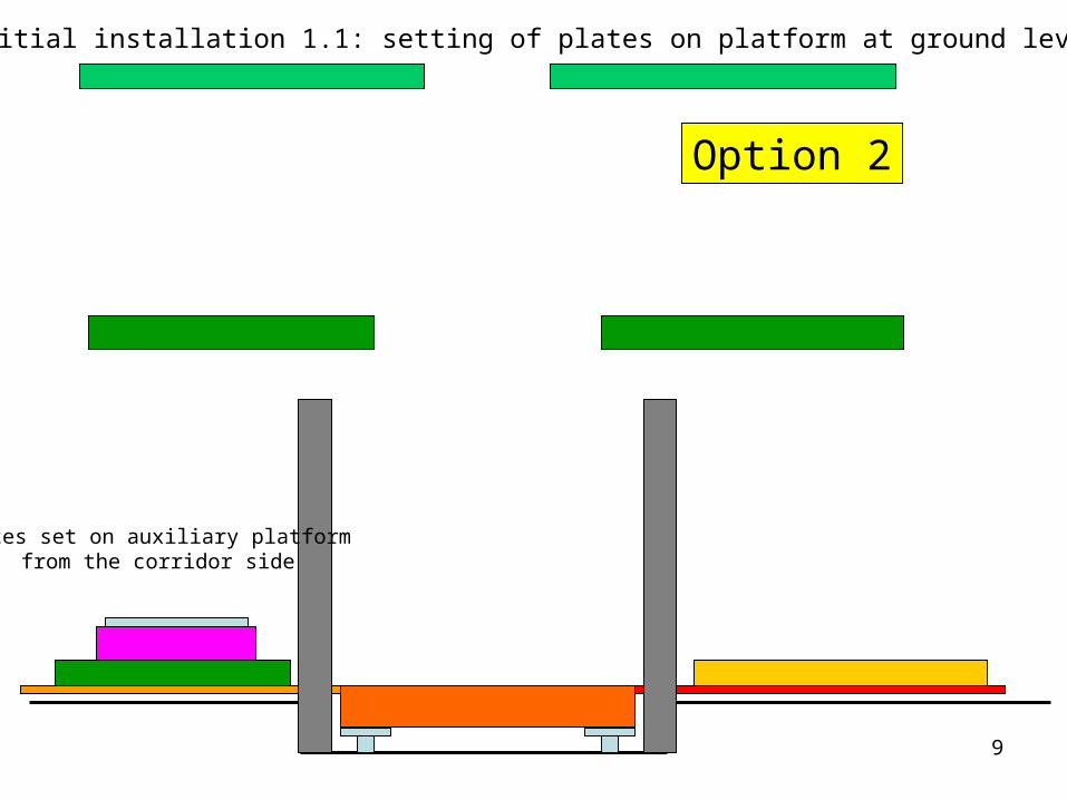
Option 2
Plates set on auxiliary platform from the corridor side
Initial installation 1.1: setting of plates on platform at ground level
10
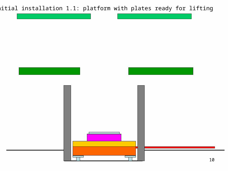
Initial installation 1.1: platform with plates ready for lifting
11
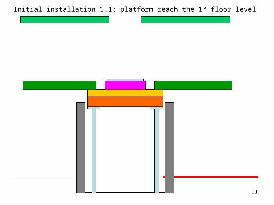
Initial installation 1.1: platform reach the 1° floor level
12
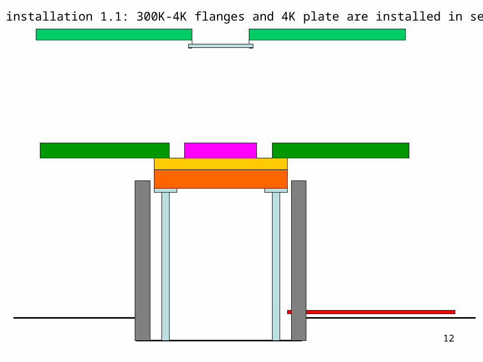
Initial installation 1.1: 300K-4K flanges and 4K plate are installed in sequence
13
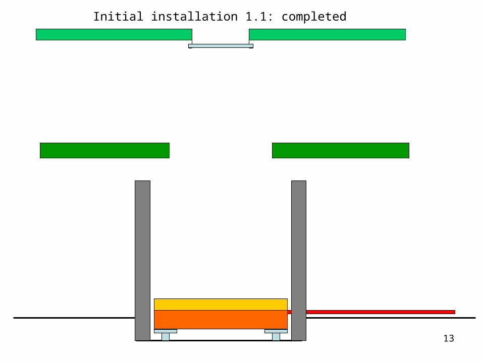
Initial installation 1.1: completed
14
1 Initial installation1.2 dry-fit of 300K-4K vessels and 40K screen
• Purpose: – check the handling procedure and sign-off of the
cable hoist system– Check vacuum tightness and deformations of OVC
and IVC
Issues/comments:• The internal screens (still, HEX, MC) must be installed in clean
conditions, so they will not be installed in this phase through the floor opening. They will be installed and removed from the clean room at the end of the dry fit
• All the screens/vessels are delivered in upright position on a basement
15
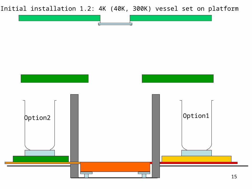
Initial installation 1.2: 4K (40K, 300K) vessel set on platform
Option1 Option2
16
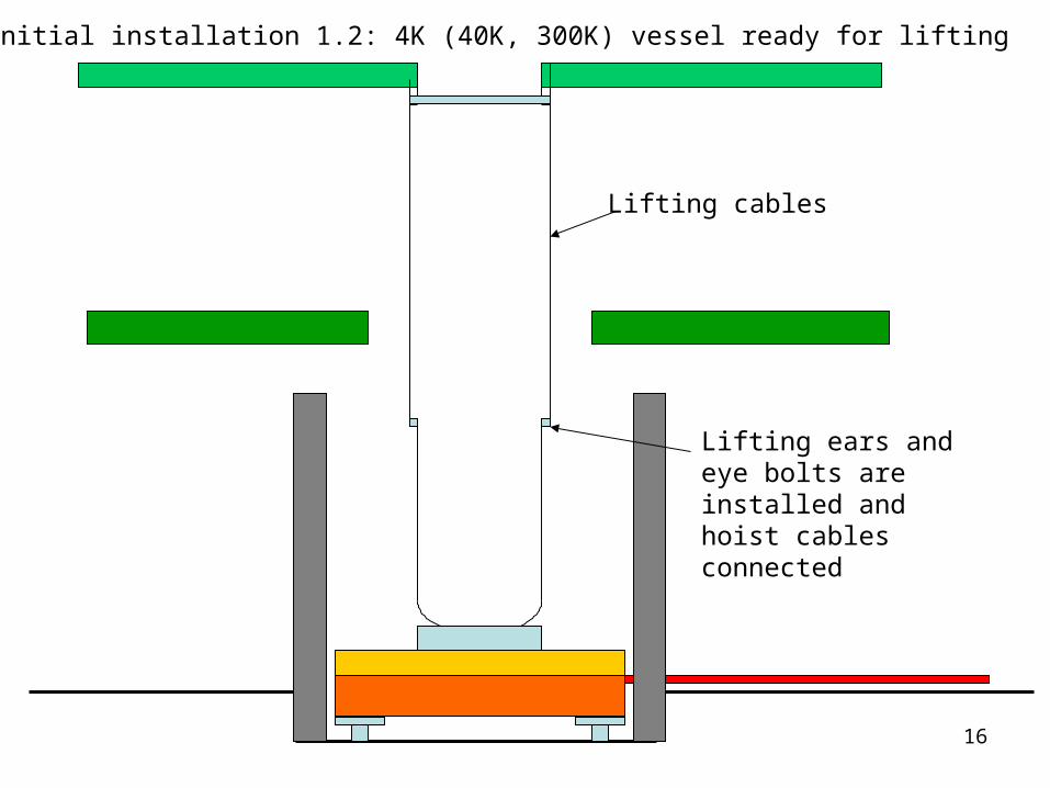
Initial installation 1.2: 4K (40K, 300K) vessel ready for lifting
Lifting ears and eye bolts are installed and hoist cables connected
Lifting cables
17
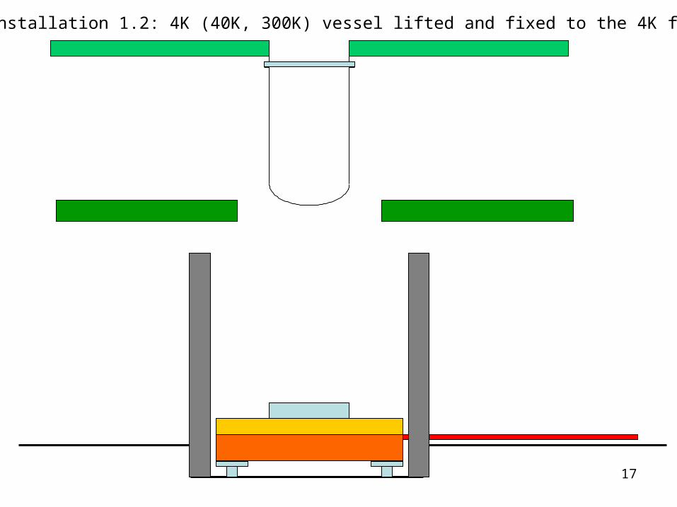
Initial installation 1.2: 4K (40K, 300K) vessel lifted and fixed to the 4K flange
18
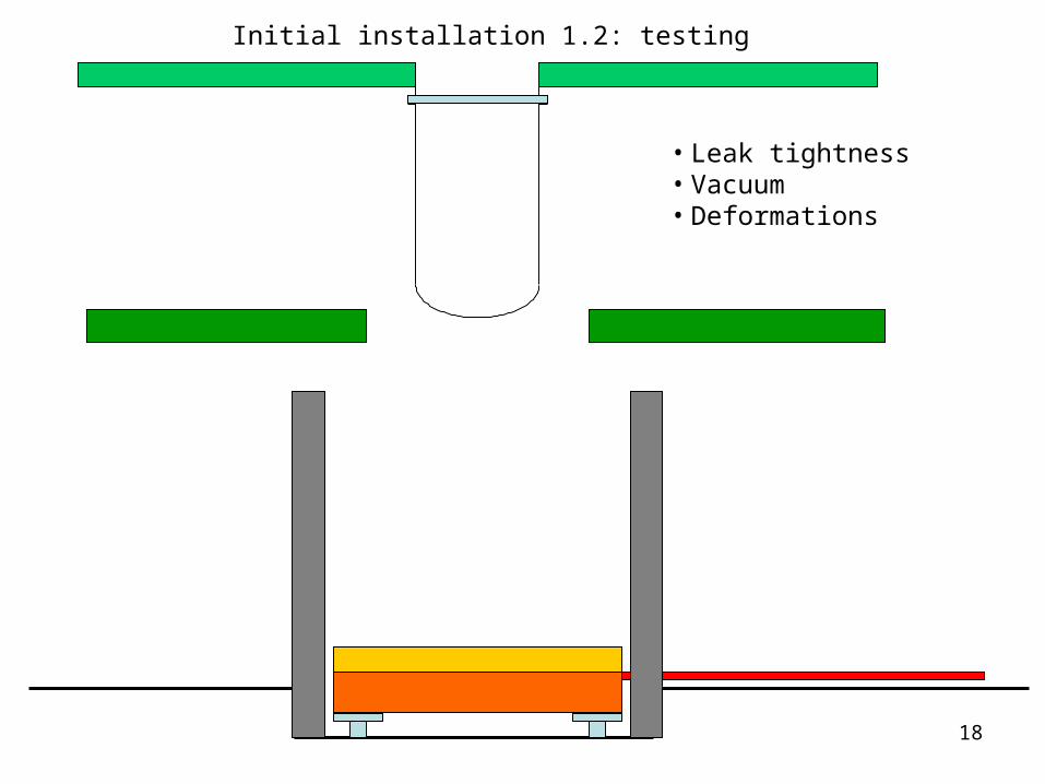
Initial installation 1.2: testing
• Leak tightness• Vacuum• Deformations
19
1 Initial installation1.3 Installation of STILL-HEX-MC plates
20
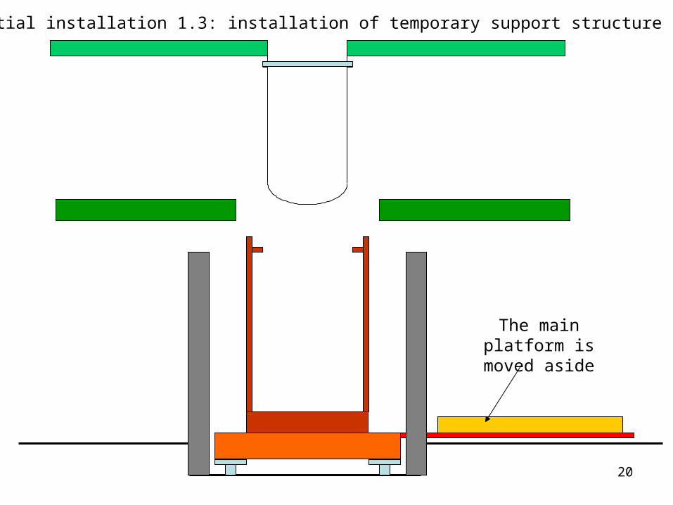
Initial installation 1.3: installation of temporary support structure
The main platform is moved aside
21
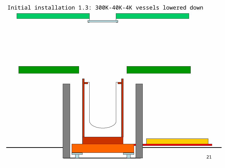
Initial installation 1.3: 300K-40K-4K vessels lowered down
22
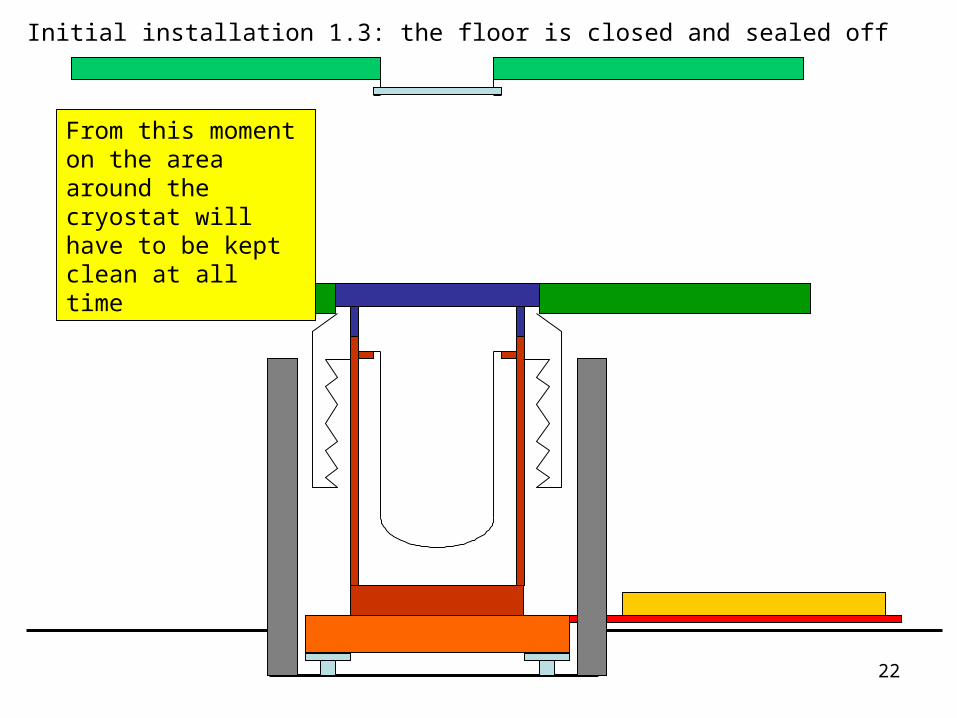
Initial installation 1.3: the floor is closed and sealed off
From this moment on the area around the cryostat will have to be kept clean at all time

23
Initial installation 1.3: installation of the STILL plate

24
Initial installation 1.3: installation of the STILL plate
25
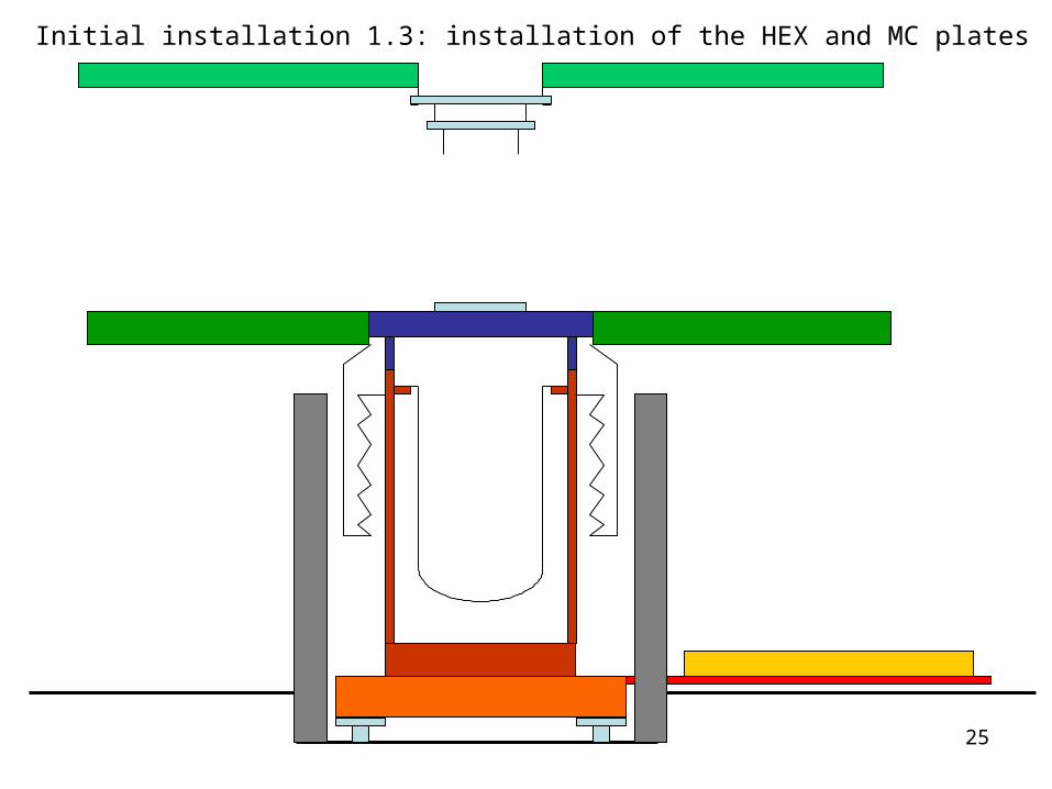
Initial installation 1.3: installation of the HEX and MC plates

26
Initial installation 1.3: installation of the HEX and MC plates
27
2. Cryostat commissioning
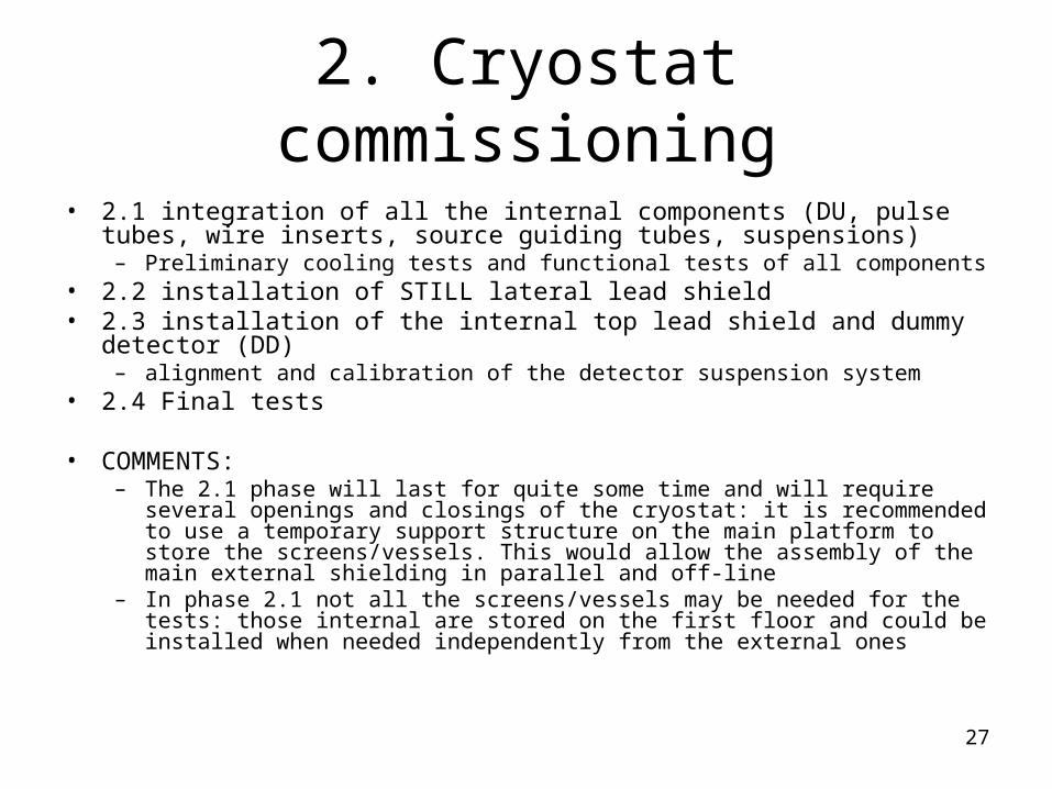
• 2.1 integration of all the internal components (DU, pulse tubes, wire inserts, source guiding tubes, suspensions)
– Preliminary cooling tests and functional tests of all components• 2.2 installation of STILL lateral lead shield• 2.3 installation of the internal top lead shield and dummy detector (DD)
– alignment and calibration of the detector suspension system • 2.4 Final tests
• COMMENTS:– The 2.1 phase will last for quite some time and will require several openings and
closings of the cryostat: it is recommended to use a temporary support structure on the main platform to store the screens/vessels. This would allow the assembly of the main external shielding in parallel and off-line
– In phase 2.1 not all the screens/vessels may be needed for the tests: those internal are stored on the first floor and could be installed when needed independently from the external ones
28
2. Cryostat commissioning
2.1 integration of all the internal components (DU, pulse tubes, wire inserts, source guiding
tubes, suspensions)
29
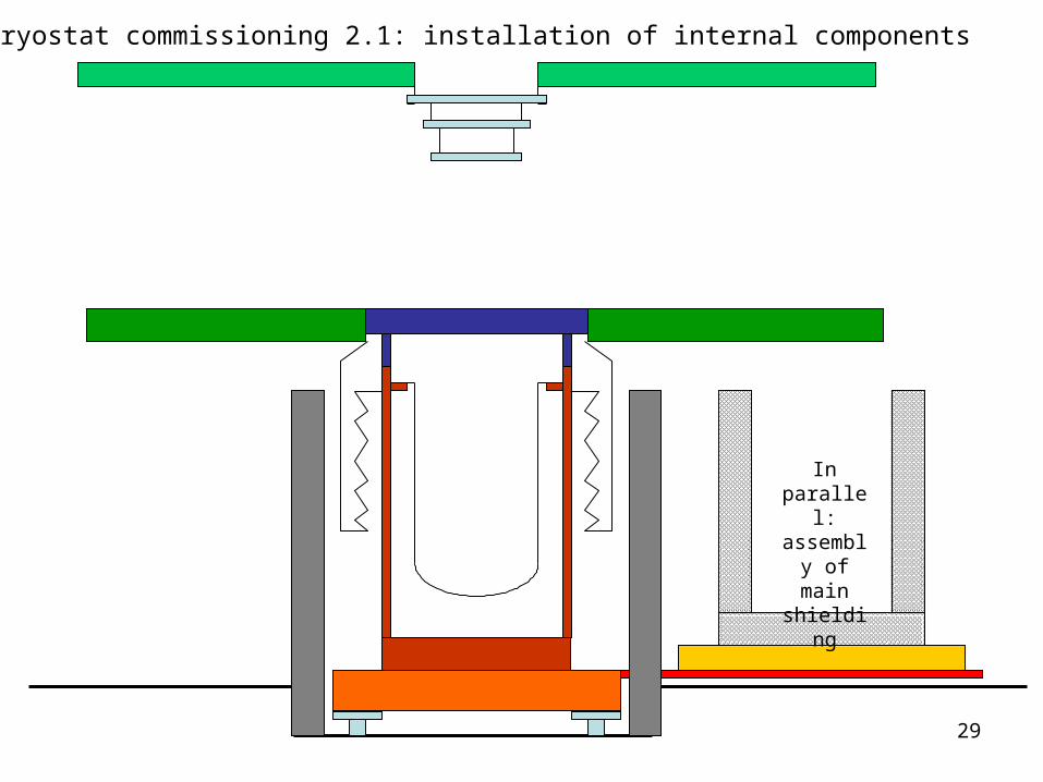
Cryostat commissioning 2.1: installation of internal components
In parallel: assembly of main
shielding
30
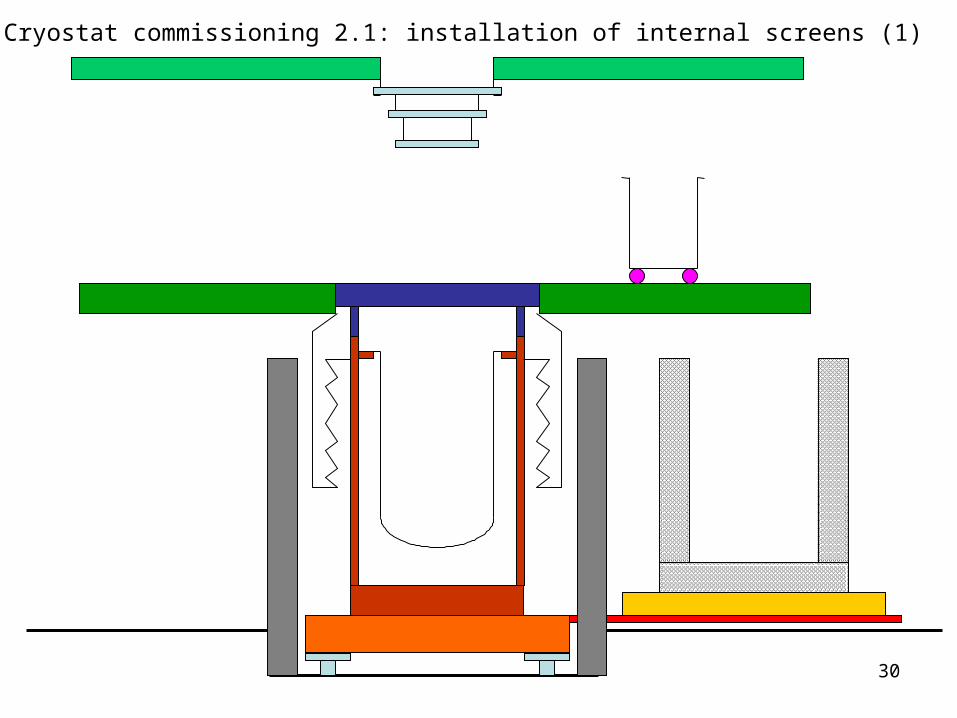
Cryostat commissioning 2.1: installation of internal screens (1)
31
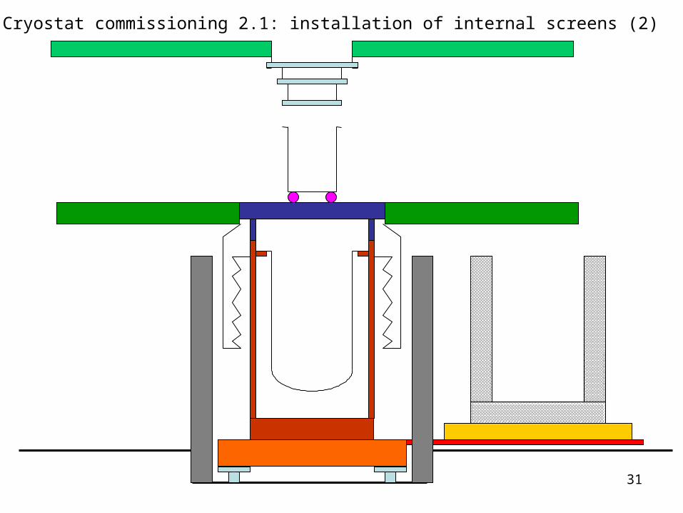
Cryostat commissioning 2.1: installation of internal screens (2)
32
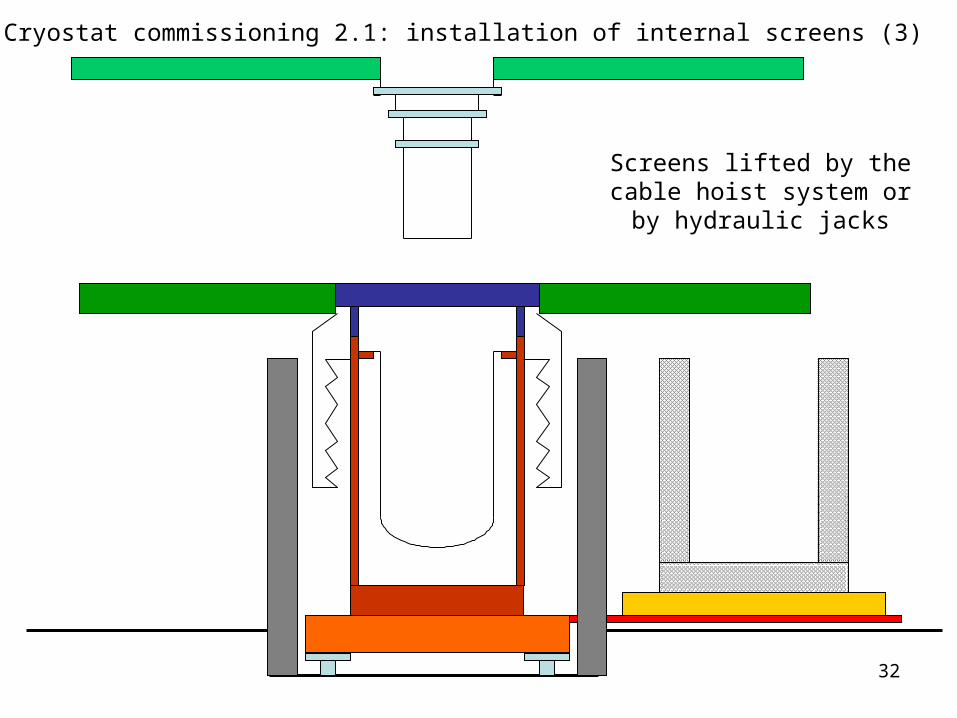
Cryostat commissioning 2.1: installation of internal screens (3)
Screens lifted by the cable hoist system or by hydraulic
jacks
33
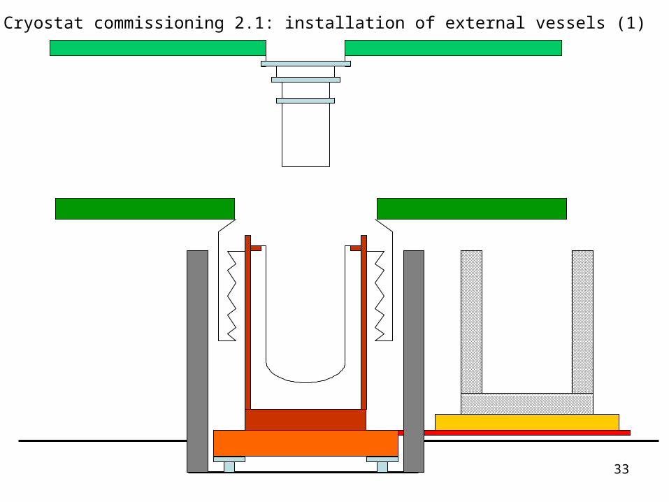
Cryostat commissioning 2.1: installation of external vessels (1)
34
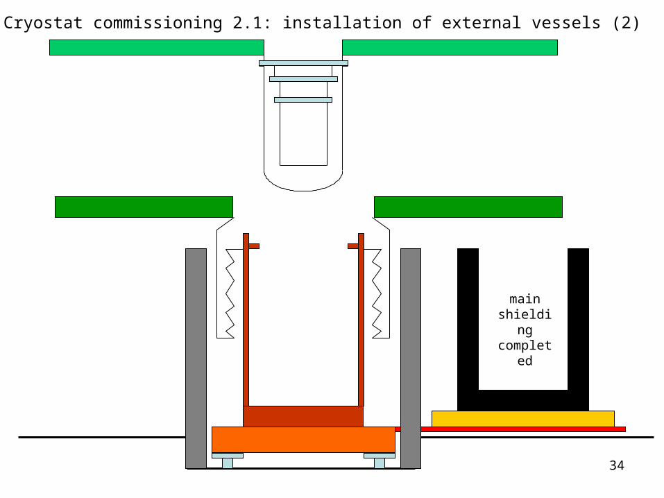
Cryostat commissioning 2.1: installation of external vessels (2)
main shielding
completed
35
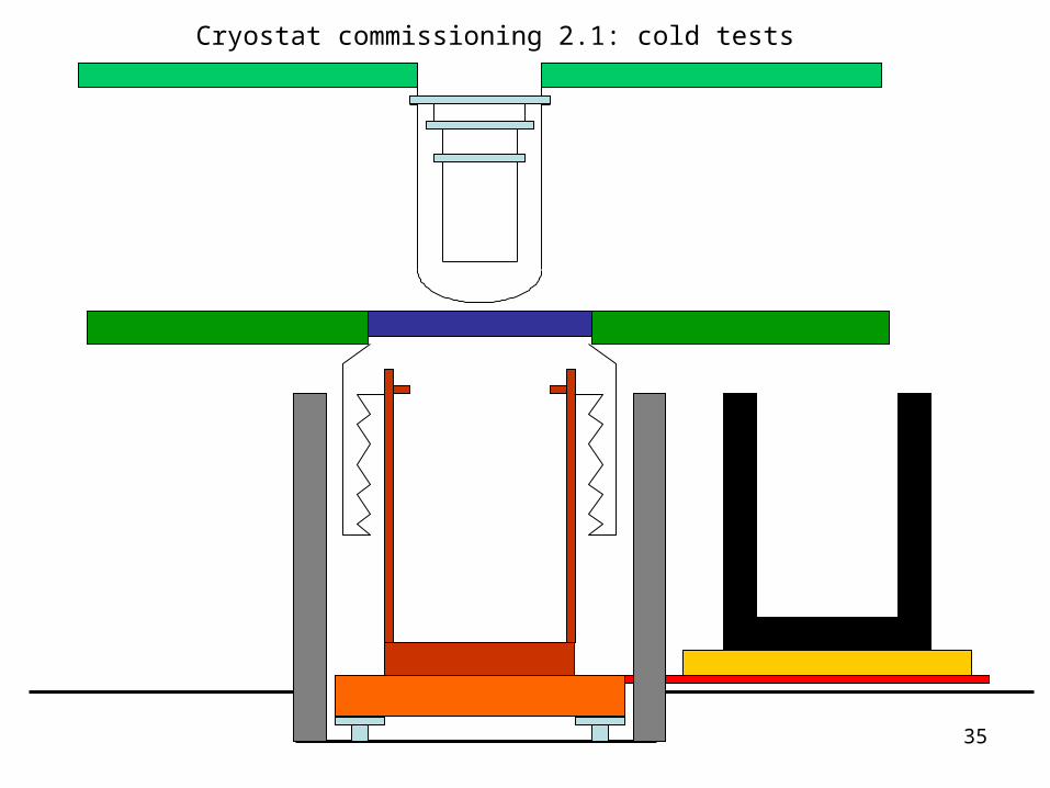
Cryostat commissioning 2.1: cold tests

36
Cryostat commissioning 2.1: cold tests
During testing:• The temporary support is removed
37
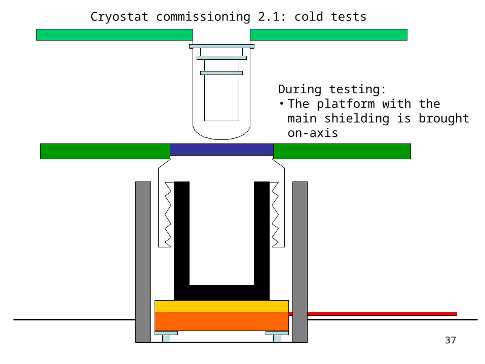
Cryostat commissioning 2.1: cold tests
During testing:• The platform with the main
shielding is brought on-axis
38
2. Cryostat commissioning
2.2 installation of STILL lateral lead shield
39
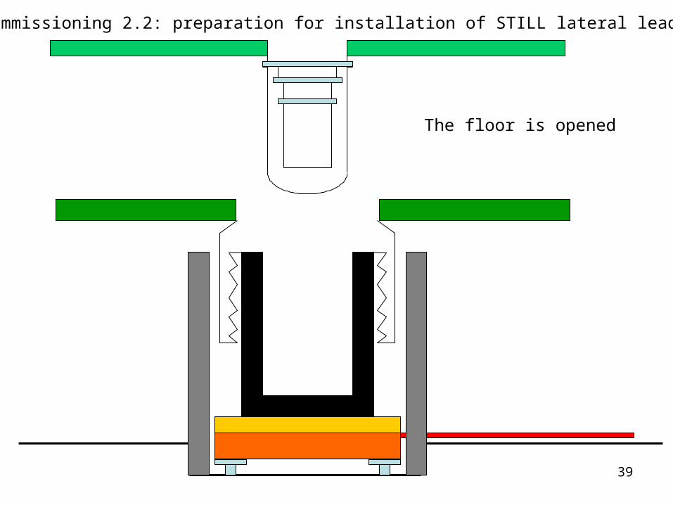
Cryostat commissioning 2.2: preparation for installation of STILL lateral lead shield (1)
The floor is opened
40
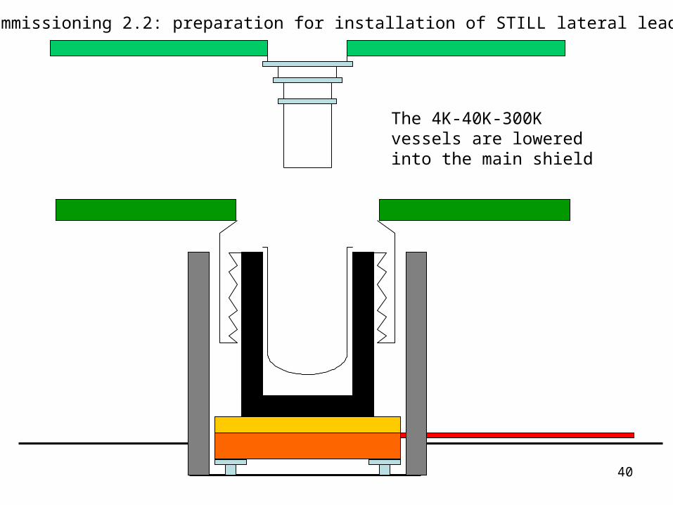
Cryostat commissioning 2.2: preparation for installation of STILL lateral lead shield (2)
The 4K-40K-300K vessels are lowered into the main shield
41
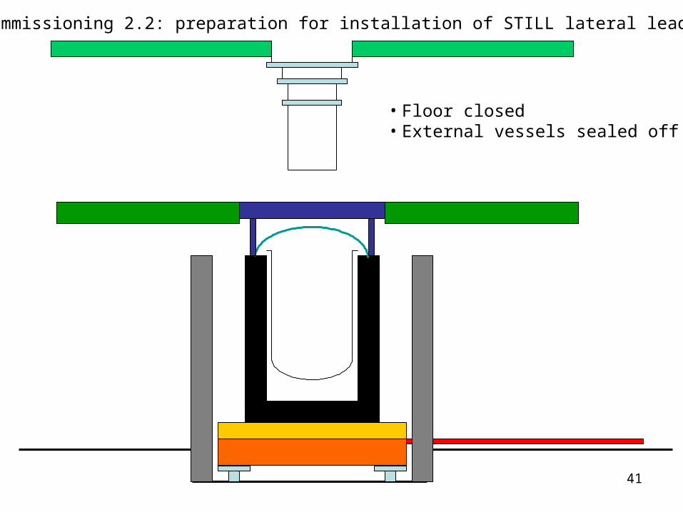
Cryostat commissioning 2.2: preparation for installation of STILL lateral lead shield (3)
• Floor closed• External vessels sealed off
42
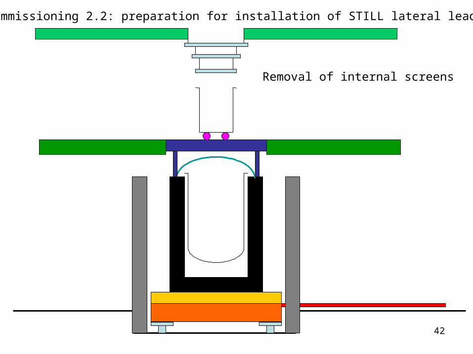
Cryostat commissioning 2.2: preparation for installation of STILL lateral lead shield (4)
Removal of internal screens
43
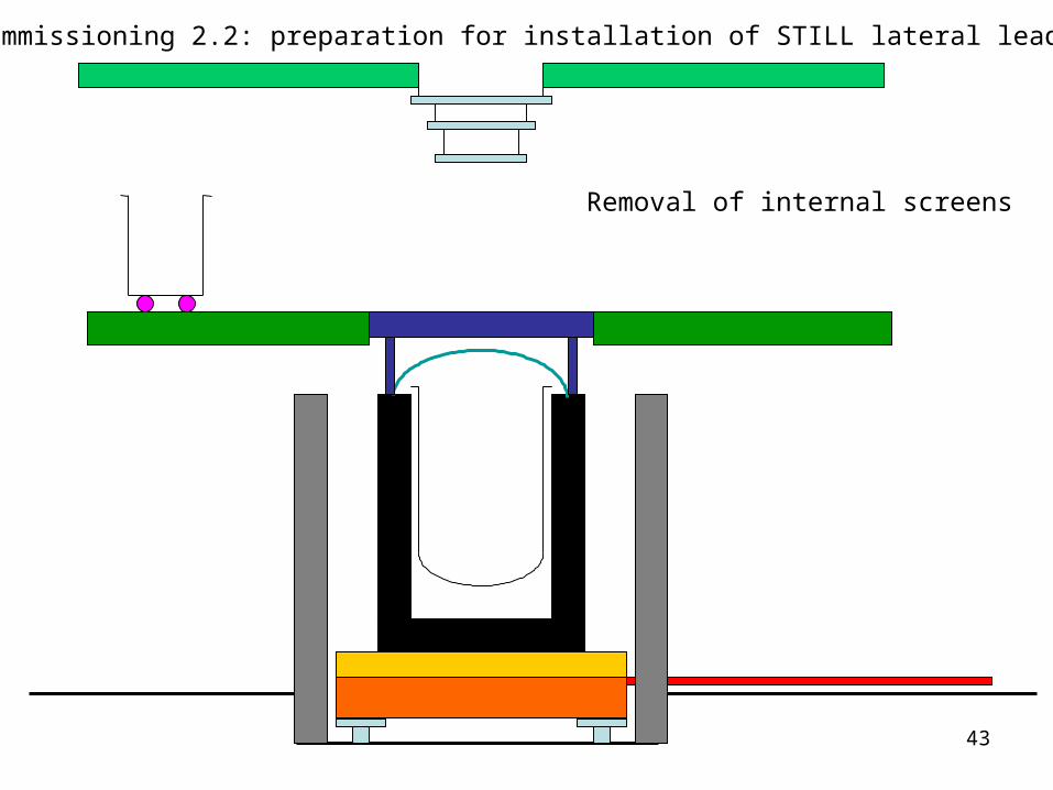
Cryostat commissioning 2.2: preparation for installation of STILL lateral lead shield (5)
Removal of internal screens
44
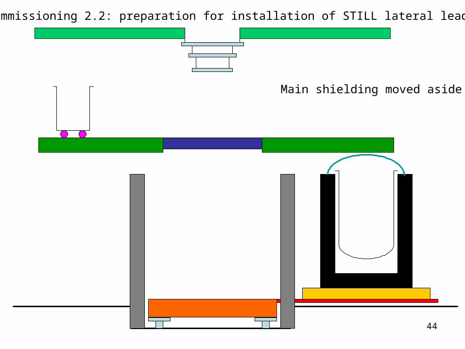
Cryostat commissioning 2.2: preparation for installation of STILL lateral lead shield (6)
Main shielding moved aside
45
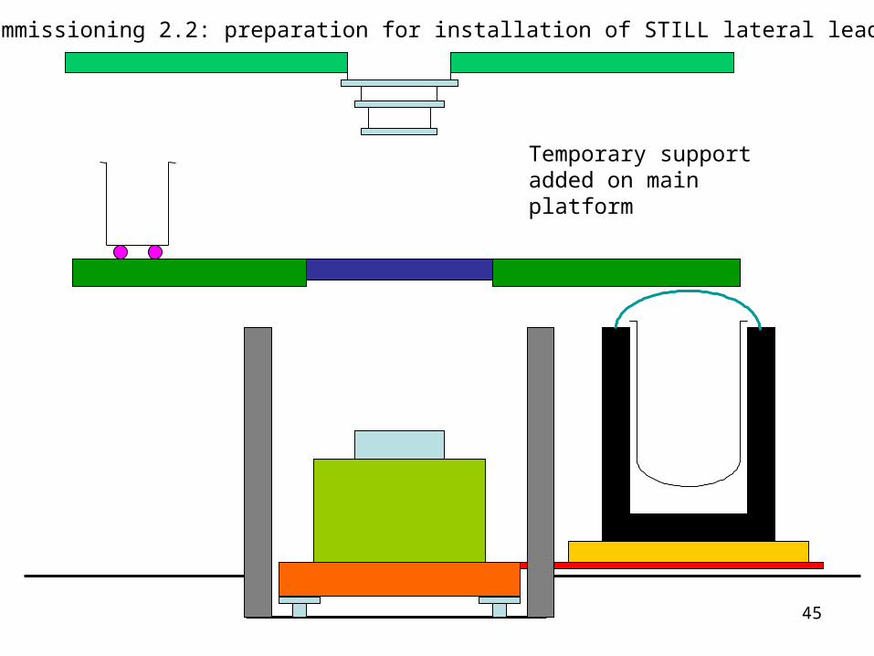
Cryostat commissioning 2.2: preparation for installation of STILL lateral lead shield (7)
Temporary support added on main platform
46
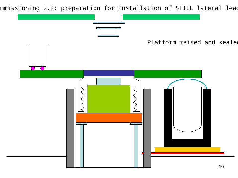
Cryostat commissioning 2.2: preparation for installation of STILL lateral lead shield (8)
Platform raised and sealed
47
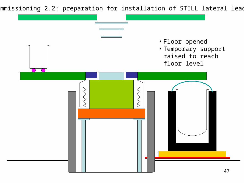
Cryostat commissioning 2.2: preparation for installation of STILL lateral lead shield (9)
• Floor opened• Temporary support raised
to reach floor level
48
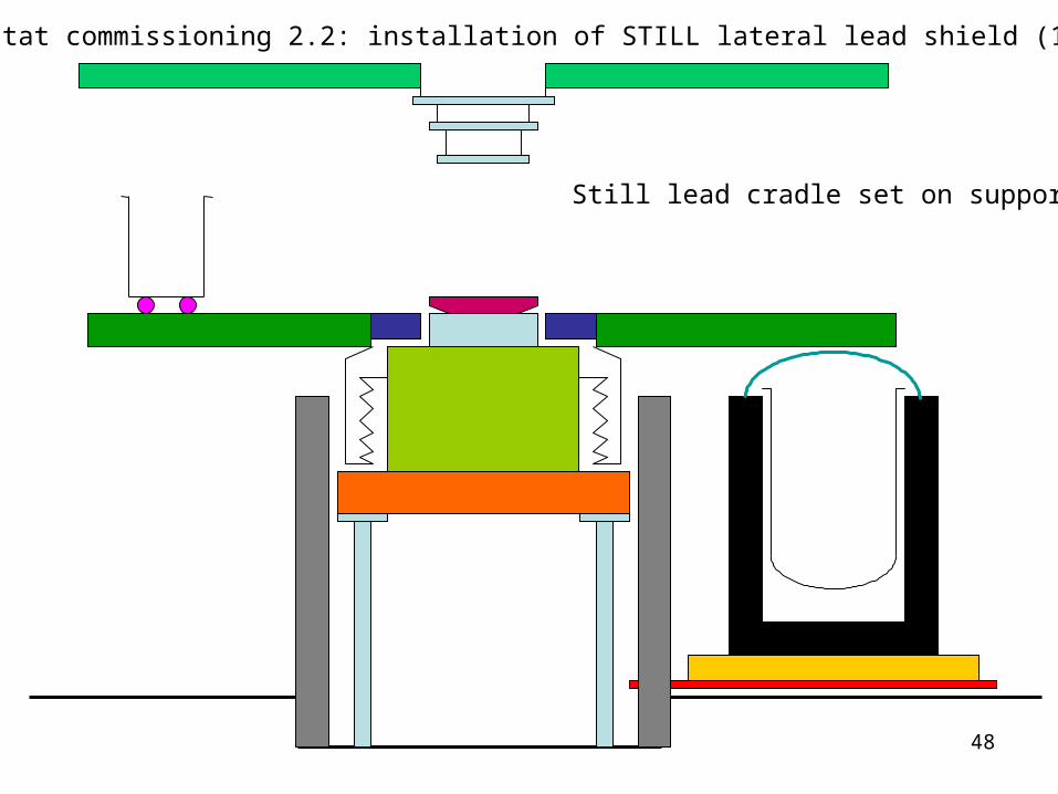
Cryostat commissioning 2.2: installation of STILL lateral lead shield (1)
Still lead cradle set on support

49
Platform lowered
Cryostat commissioning 2.2: installation of STILL lateral lead shield (2)
50
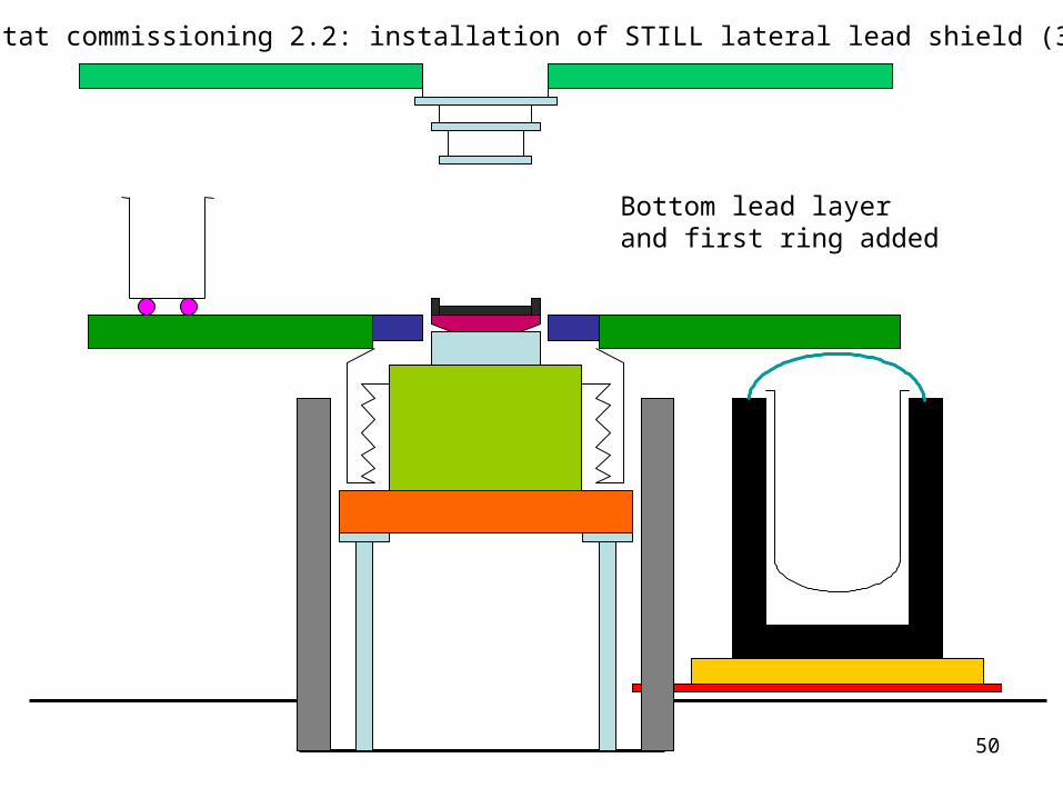
Cryostat commissioning 2.2: installation of STILL lateral lead shield (3)
Bottom lead layer and first ring added
51
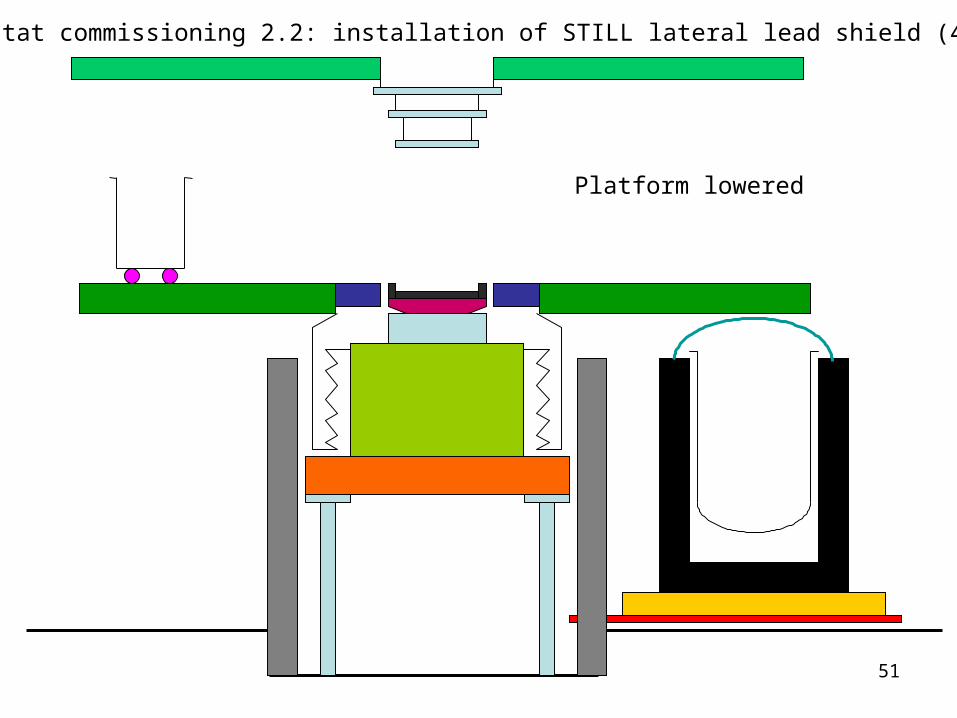
Cryostat commissioning 2.2: installation of STILL lateral lead shield (4)
Platform lowered

52
Cryostat commissioning 2.2: installation of STILL lateral lead shield (5)
Installation of 2° lead ring
53
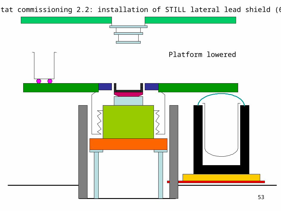
Cryostat commissioning 2.2: installation of STILL lateral lead shield (6)
Platform lowered
54
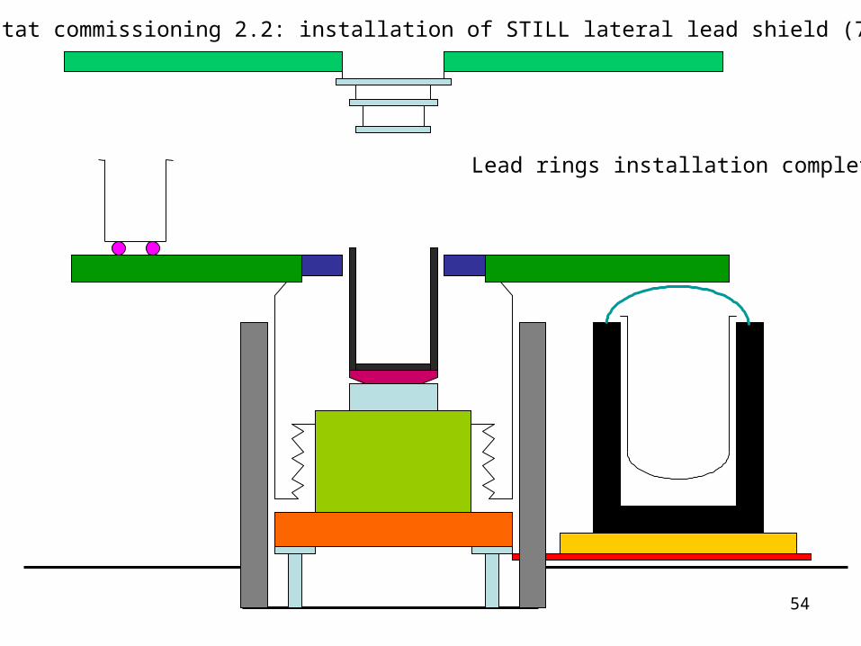
Cryostat commissioning 2.2: installation of STILL lateral lead shield (7)
Lead rings installation completed
55
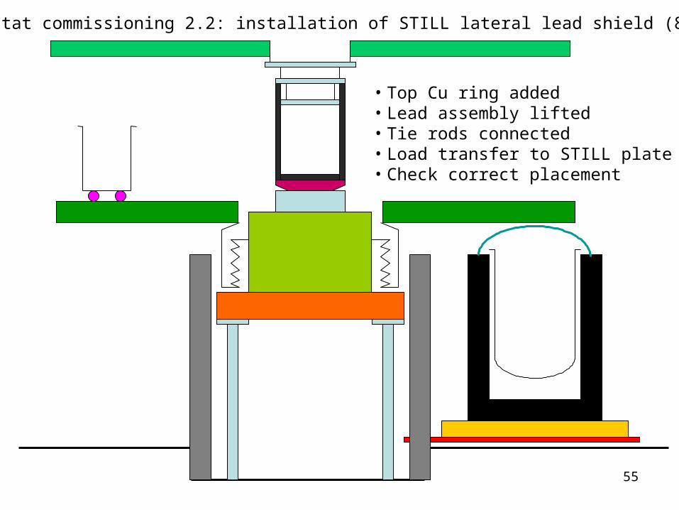
Cryostat commissioning 2.2: installation of STILL lateral lead shield (8)
• Top Cu ring added• Lead assembly lifted• Tie rods connected• Load transfer to STILL plate• Check correct placement
56
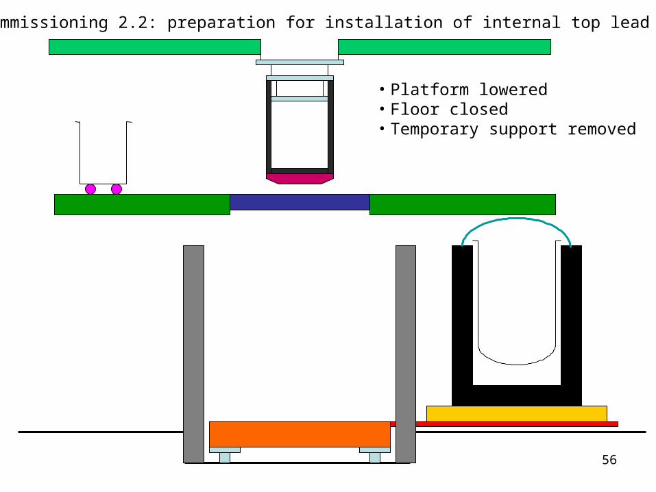
Cryostat commissioning 2.2: preparation for installation of internal top lead shield (1)
• Platform lowered• Floor closed• Temporary support removed
57
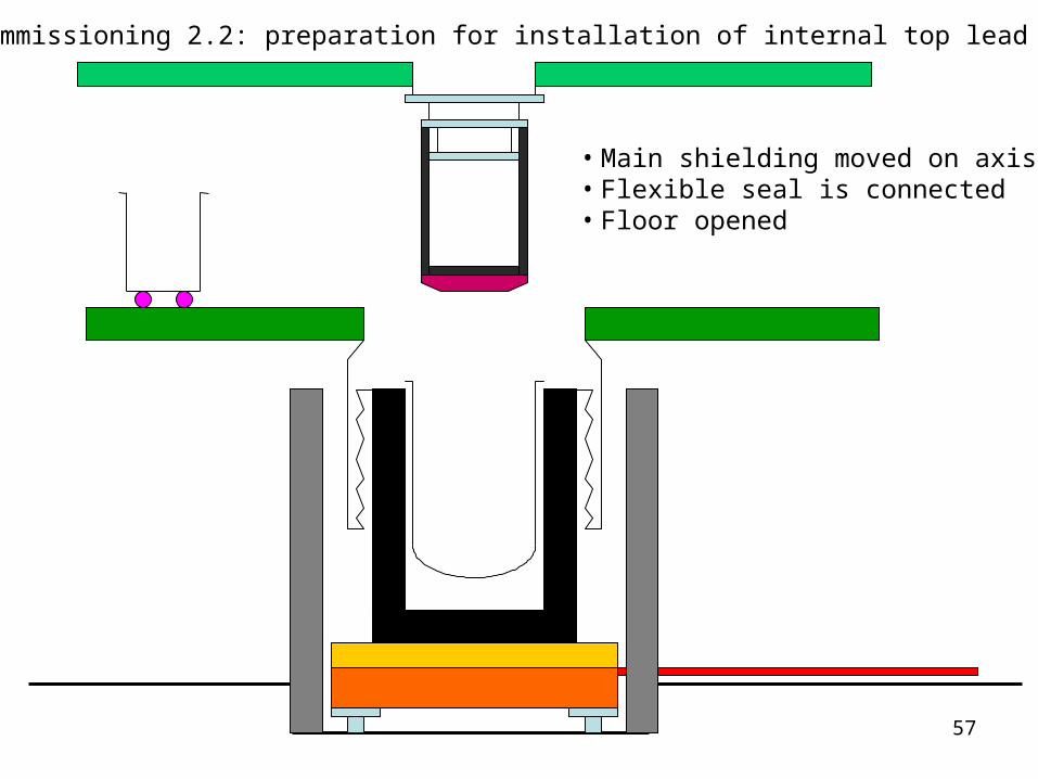
• Main shielding moved on axis• Flexible seal is connected• Floor opened
Cryostat commissioning 2.2: preparation for installation of internal top lead shield (2)
58
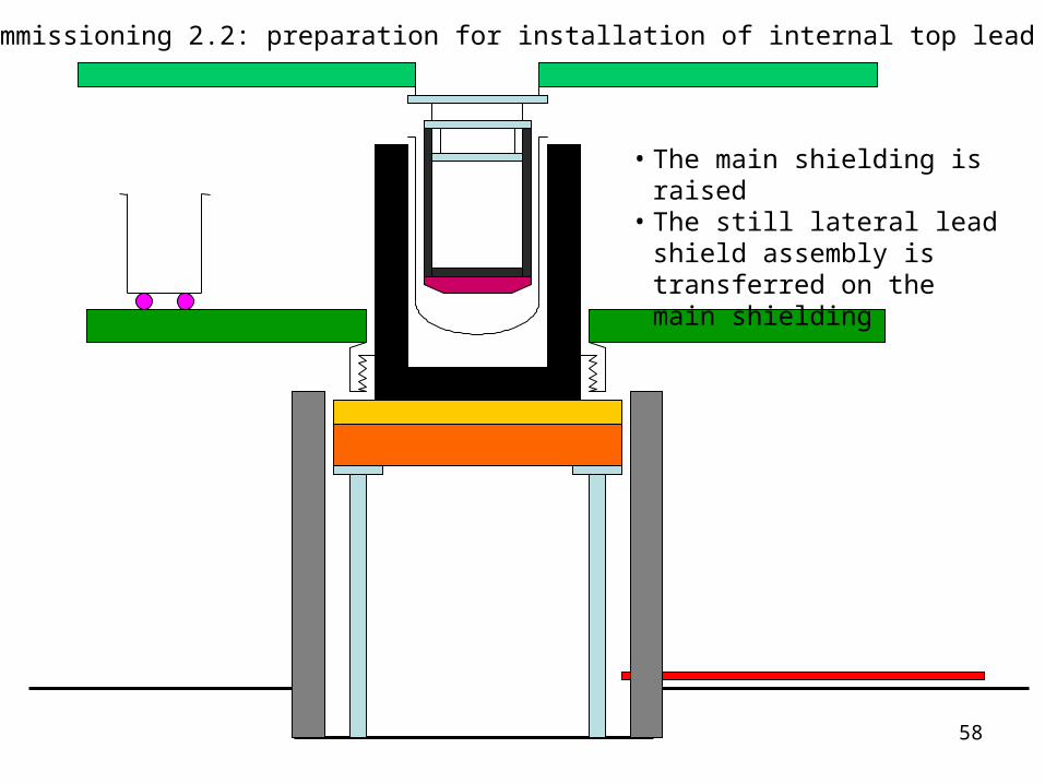
• The main shielding is raised• The still lateral lead shield
assembly is transferred on the main shielding
Cryostat commissioning 2.2: preparation for installation of internal top lead shield (3)
59
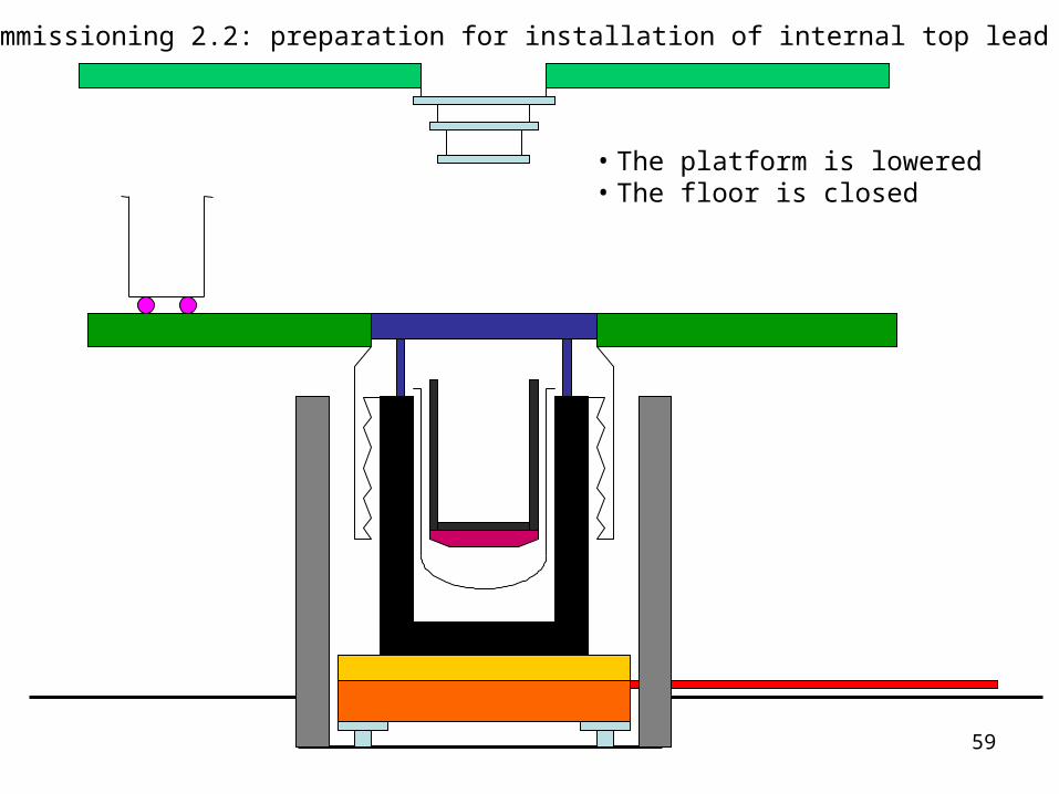
• The platform is lowered• The floor is closed
Cryostat commissioning 2.2: preparation for installation of internal top lead shield (4)
60
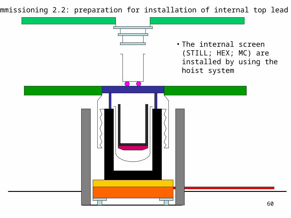
• The internal screen (STILL; HEX; MC) are installed by using the hoist system
Cryostat commissioning 2.2: preparation for installation of internal top lead shield (5)
61
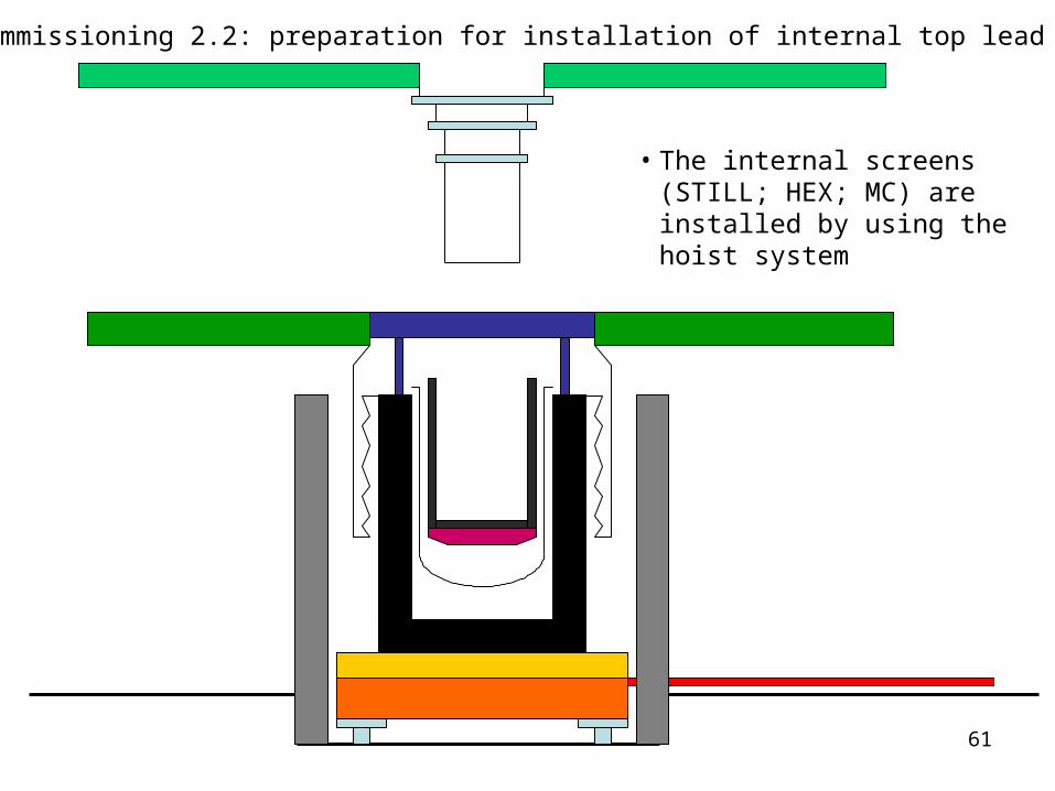
• The internal screens (STILL; HEX; MC) are installed by using the hoist system
Cryostat commissioning 2.2: preparation for installation of internal top lead shield (6)
62
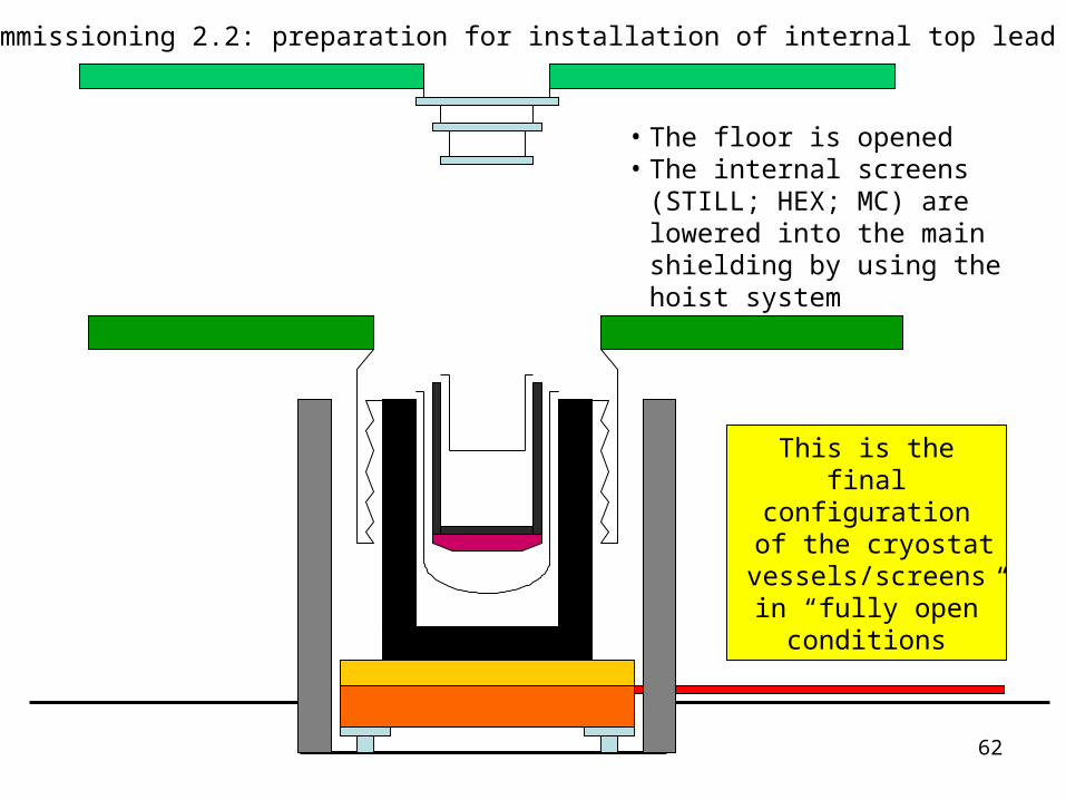
• The floor is opened• The internal screens (STILL;
HEX; MC) are lowered into the main shielding by using the hoist system
Cryostat commissioning 2.2: preparation for installation of internal top lead shield (7)
This is the final configuration
of the cryostat vessels/screens in “fully open”
conditions
63
2. Cryostat commissioning
2.3 installation of the STILL internal top lead shield and dummy detector (DD)
64
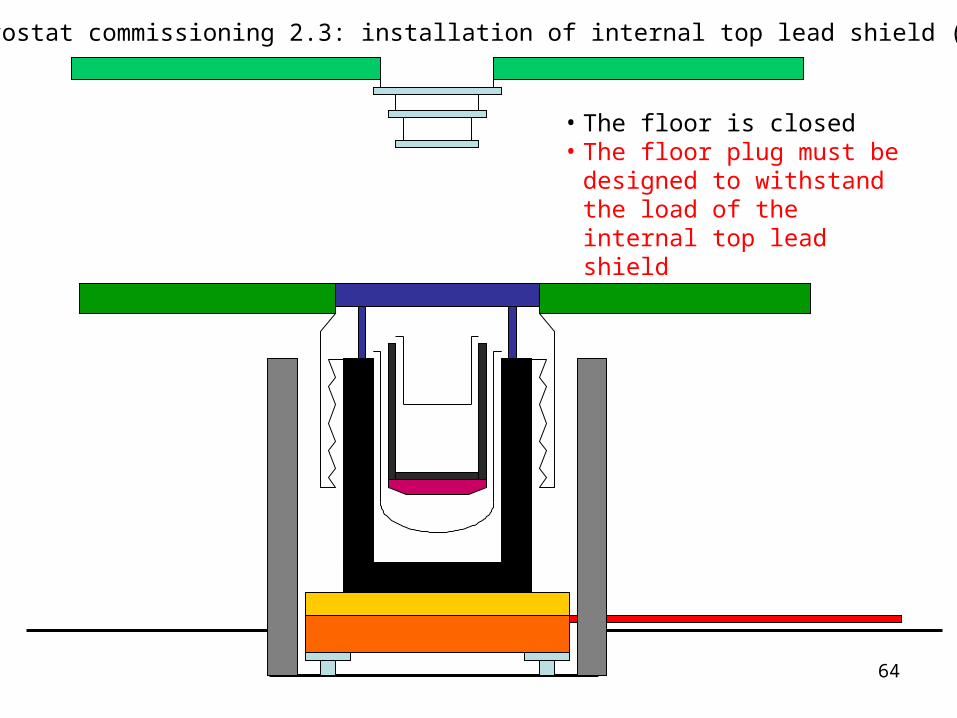
• The floor is closed• The floor plug must be
designed to withstand the load of the internal top lead shield
Cryostat commissioning 2.3: installation of internal top lead shield (1)
65
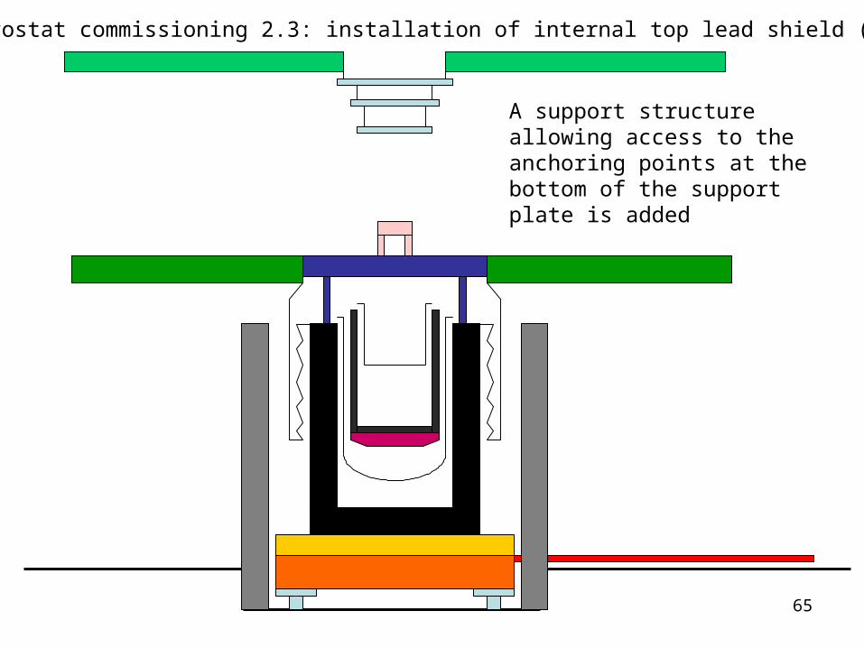
A support structure allowing access to the anchoring points at the bottom of the support plate is added
Cryostat commissioning 2.3: installation of internal top lead shield (2)
66
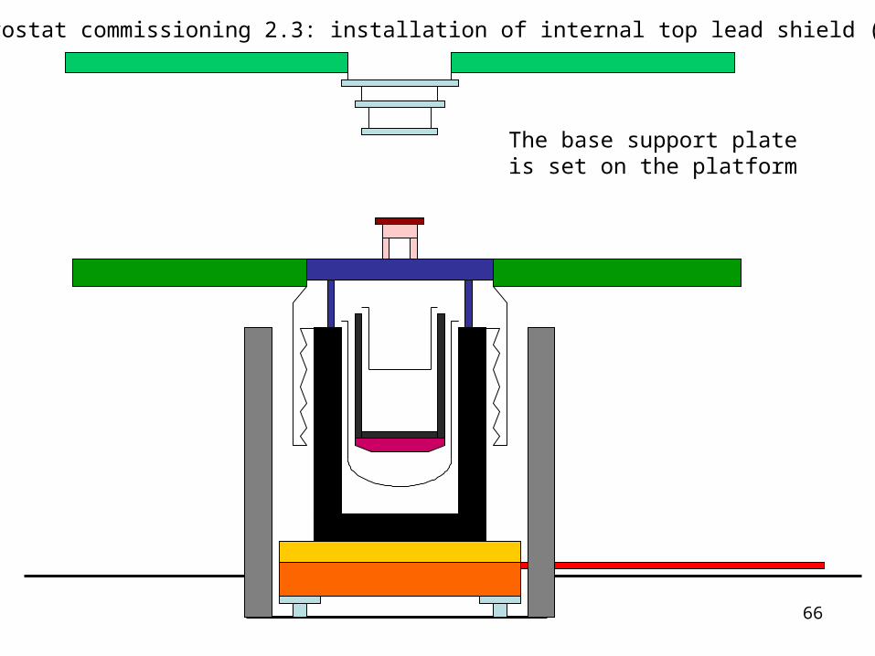
The base support plate is set on the platform
Cryostat commissioning 2.3: installation of internal top lead shield (3)
67
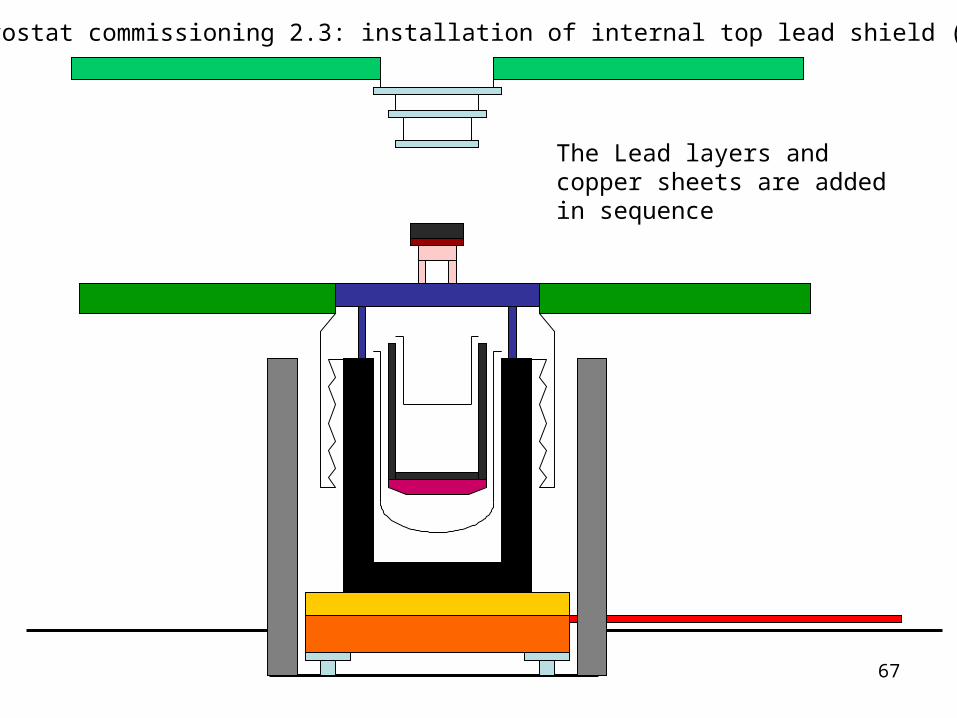
The Lead layers and copper sheets are added in sequence
Cryostat commissioning 2.3: installation of internal top lead shield (4)
68
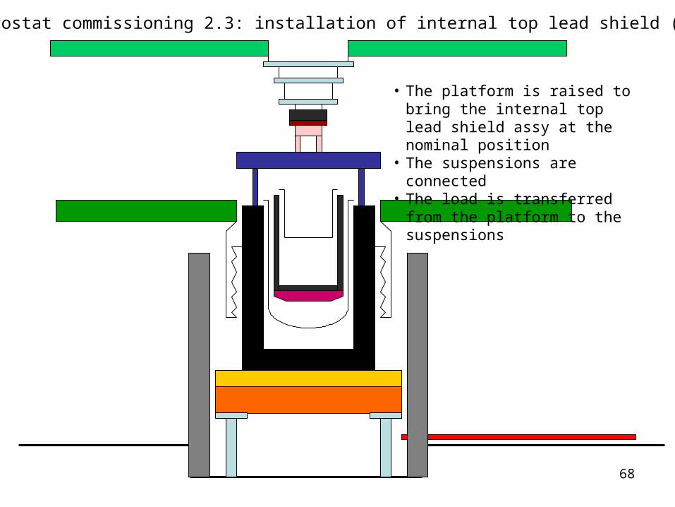
• The platform is raised to bring the internal top lead shield assy at the nominal position
• The suspensions are connected• The load is transferred from the
platform to the suspensions
Cryostat commissioning 2.3: installation of internal top lead shield (5)
69
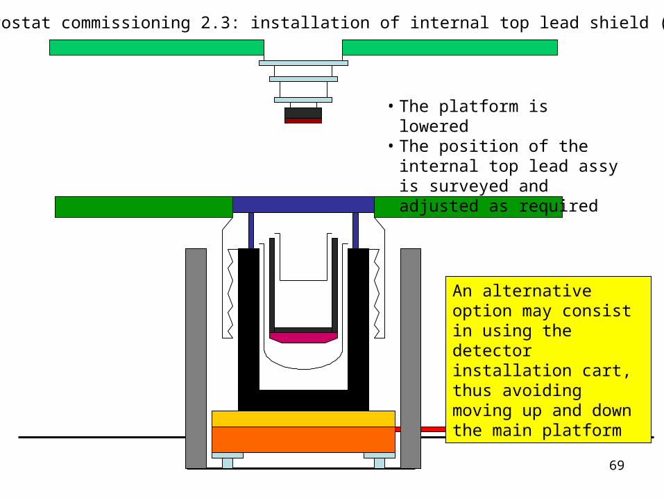
• The platform is lowered• The position of the internal top
lead assy is surveyed and adjusted as required
Cryostat commissioning 2.3: installation of internal top lead shield (6)
An alternative option may consist in using the detector installation cart, thus avoiding moving up and down the main platform
70
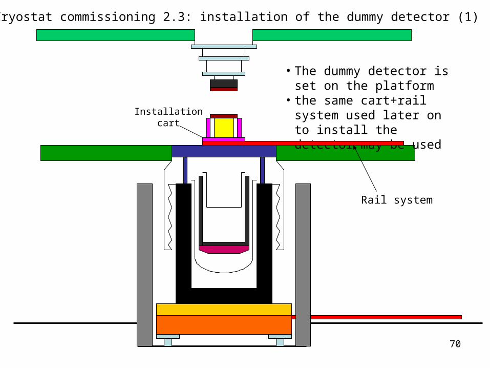
• The dummy detector is set on the platform
• the same cart+rail system used later on to install the detector may be used
Cryostat commissioning 2.3: installation of the dummy detector (1)
Installationcart
Rail system
71
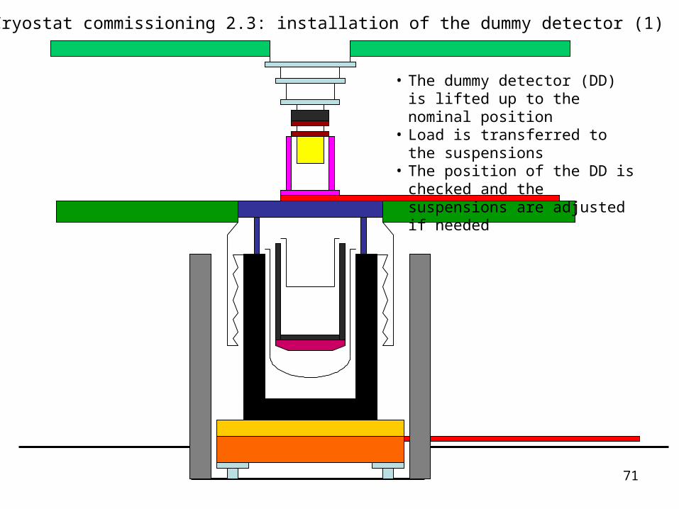
• The dummy detector (DD) is lifted up to the nominal position
• Load is transferred to the suspensions
• The position of the DD is checked and the suspensions are adjusted if needed
Cryostat commissioning 2.3: installation of the dummy detector (1)
72
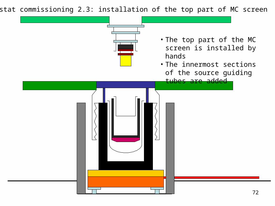
• The top part of the MC screen is installed by hands
• The innermost sections of the source guiding tubes are added
Cryostat commissioning 2.3: installation of the top part of MC screen

73
Cryostat commissioning 2.3: installation of the STILL top lead ring
74
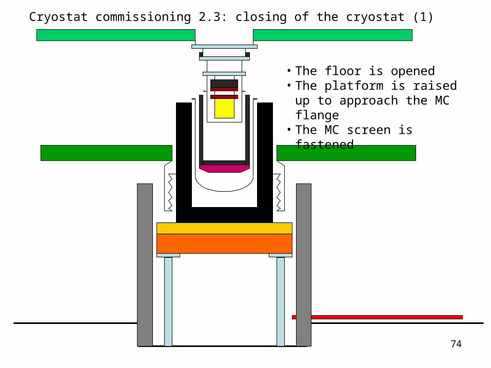
• The floor is opened• The platform is raised up to
approach the MC flange• The MC screen is fastened
Cryostat commissioning 2.3: closing of the cryostat (1)
75
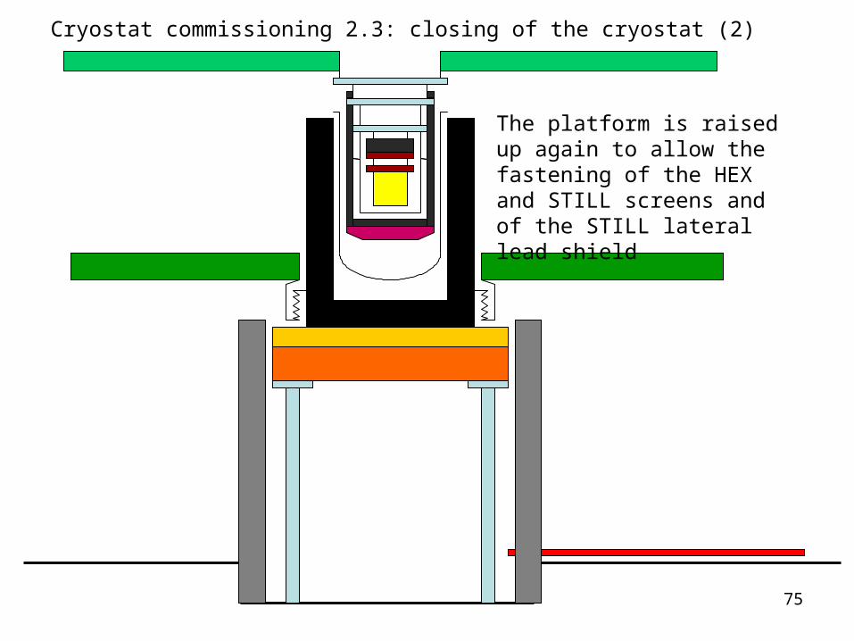
The platform is raised up again to allow the fastening of the HEX and STILL screens and of the STILL lateral lead shield
Cryostat commissioning 2.3: closing of the cryostat (2)
76
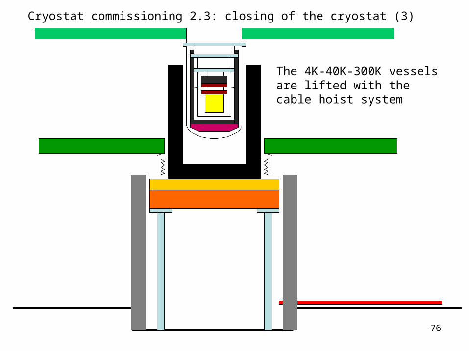
The 4K-40K-300K vessels are lifted with the cable hoist system
Cryostat commissioning 2.3: closing of the cryostat (3)
77
2. Cryostat commissioning 2.4 Final tests
The cryostat is cooled down and the final commissioning tests are carried out
including the full test of the calibration system
78
3. Detector installation
3.1 Preparation for the installation (removal of dummy detector)
3.2 detector installation
79
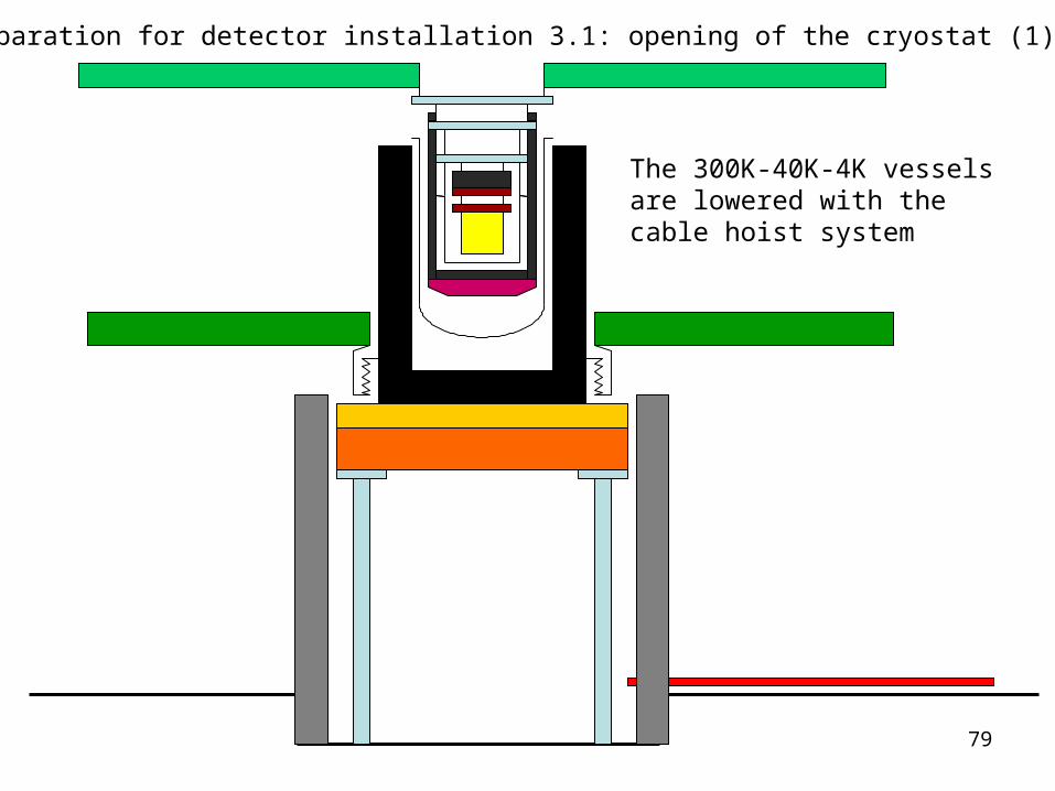
The 300K-40K-4K vessels are lowered with the cable hoist system
Preparation for detector installation 3.1: opening of the cryostat (1)
80
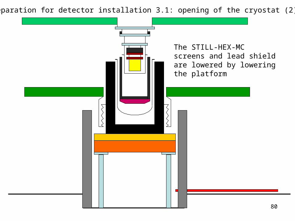
The STILL-HEX-MC screens and lead shield are lowered by lowering the platform
Preparation for detector installation 3.1: opening of the cryostat (2)

81
• The platform is fully lowered• The floor is closed
Preparation for detector installation 3.1: opening of the cryostat (3)
82
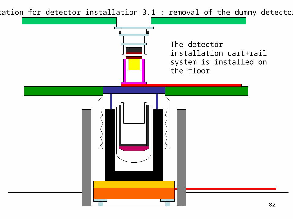
The detector installation cart+rail system is installed on the floor
Preparation for detector installation 3.1 : removal of the dummy detector (1)

83
The dummy detector is lowered
Preparation for detector installation 3.1 : removal of the dummy detector (2)
84
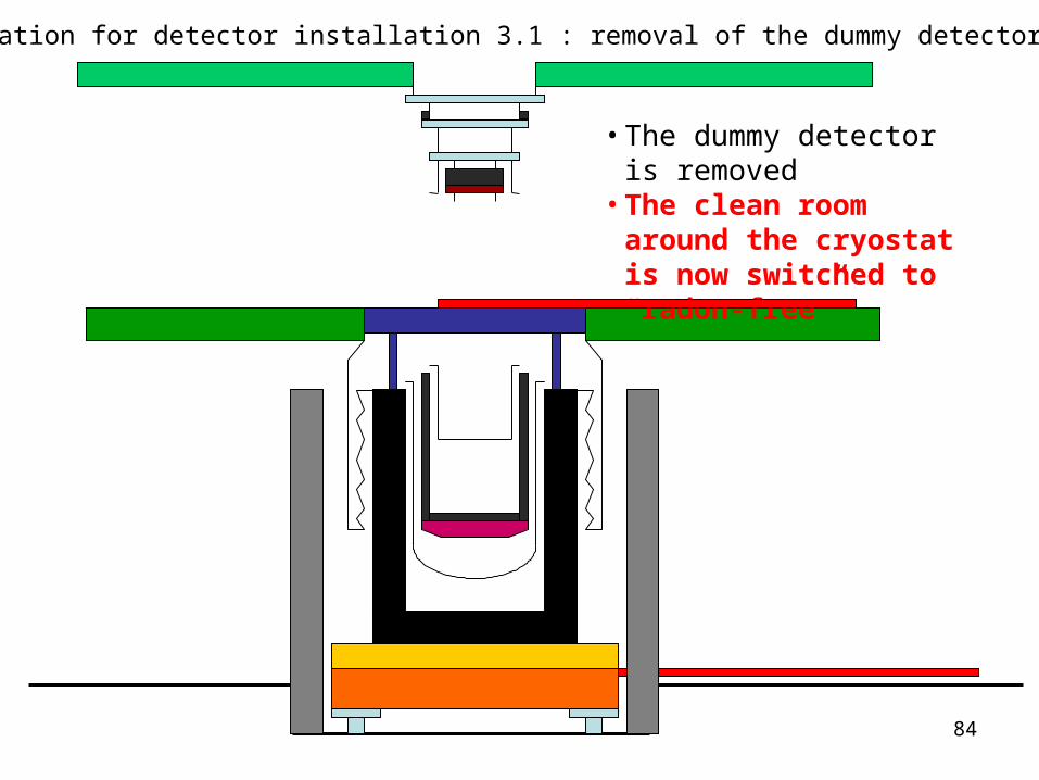
• The dummy detector is removed
• The clean room around the cryostat is now switched to “radon-free”
Preparation for detector installation 3.1 : removal of the dummy detector (2)
85
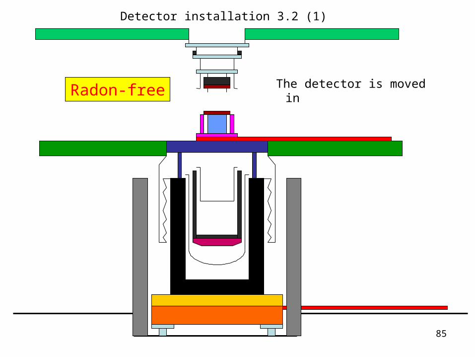
The detector is moved in
Detector installation 3.2 (1)
Radon-free
86
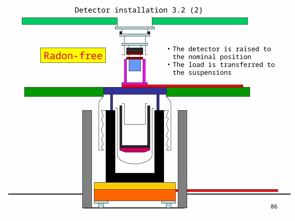
• The detector is raised to the nominal position
• The load is transferred to the suspensions
Radon-free
Detector installation 3.2 (2)
87
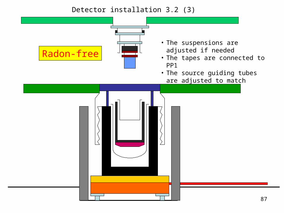
• The suspensions are adjusted if needed
• The tapes are connected to PP1• The source guiding tubes are
adjusted to match
Radon-free
Detector installation 3.2 (3)

88
• The floor is opened• The platform is raised• The MC-HEX-STILL screen and the
STILL lead shield are fastened to the corresponding plates
• The detector is flushed with N2
Radon-free
Detector installation 3.2 (4)
89
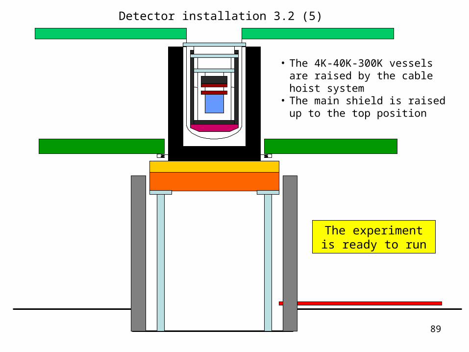
• The 4K-40K-300K vessels are raised by the cable hoist system
• The main shield is raised up to the top position
The experiment is ready to run
Detector installation 3.2 (5)
90
4. maintenance
Subset of the procedures followed for the detector installation