Embed Size (px)
Citation preview
1
Ι © D
assa
ult S
ystè
mes
Ι Co
nfid
entia
l Inf
orm
atio
n Ι
SolidWorks Software Lesson 6
2
Ι © D
assa
ult S
ystè
mes
Ι Co
nfid
entia
l Inf
orm
atio
n Ι
Engineering Drawings
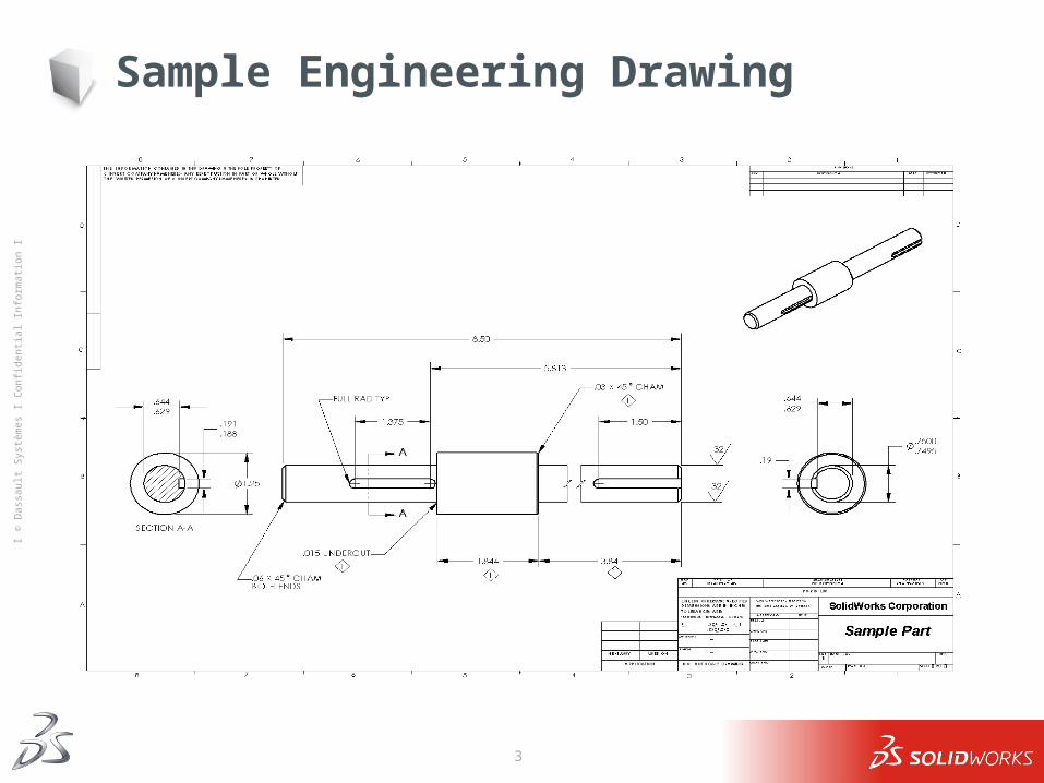
Drawings communicate three things about the objects they represent: Shape – Views communicate the shape of an object. Size – Dimensions communicate the size of an object. Other information – Notes communicate non-graphic
information about manufacturing processes such as drill, ream, bore, paint, plate, grind, heat treat, remove burrs, and so forth.
3
Ι © D
assa
ult S
ystè
mes
Ι Co
nfid
entia
l Inf
orm
atio
n Ι
Sample Engineering Drawing
4
Ι © D
assa
ult S
ystè
mes
Ι Co
nfid
entia
l Inf
orm
atio
n Ι
General Drawing Rules – Views
The general characteristics of an object will determine what views are required to describe its shape.
Most objects can be described using three properly selected views. Top, Right, and Front. Isometric are also usually included. Sometimes you can use fewer. However, sometimes more are needed.
5
Ι © D
assa
ult S
ystè
mes
Ι Co
nfid
entia
l Inf
orm
atio
n Ι
Drawing Views
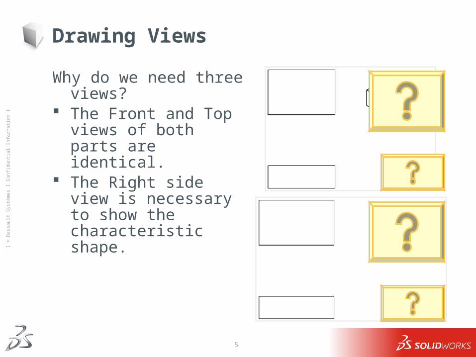
Why do we need three views? The Front and Top views of
both parts are identical. The Right side view is
necessary to show the characteristic shape.
6
Ι © D
assa
ult S
ystè
mes
Ι Co
nfid
entia
l Inf
orm
atio
n Ι
Drawing Views: When Three is not Enough
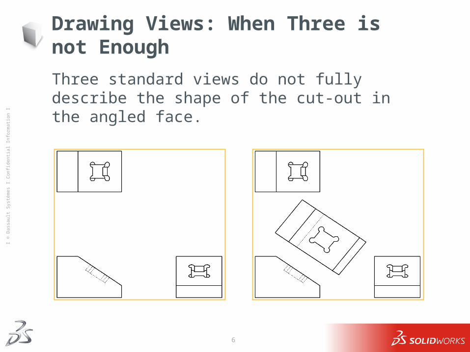
Three standard views do not fully describe the shape of the cut-out in the angled face.
7
Ι © D
assa
ult S
ystè
mes
Ι Co
nfid
entia
l Inf
orm
atio
n Ι
Drawing Views: When Three is too Many
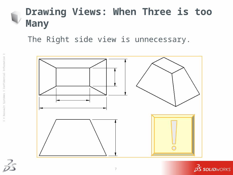
The Right side view is unnecessary.
8
Ι © D
assa
ult S
ystè
mes
Ι Co
nfid
entia
l Inf
orm
atio
n Ι
Dimensions
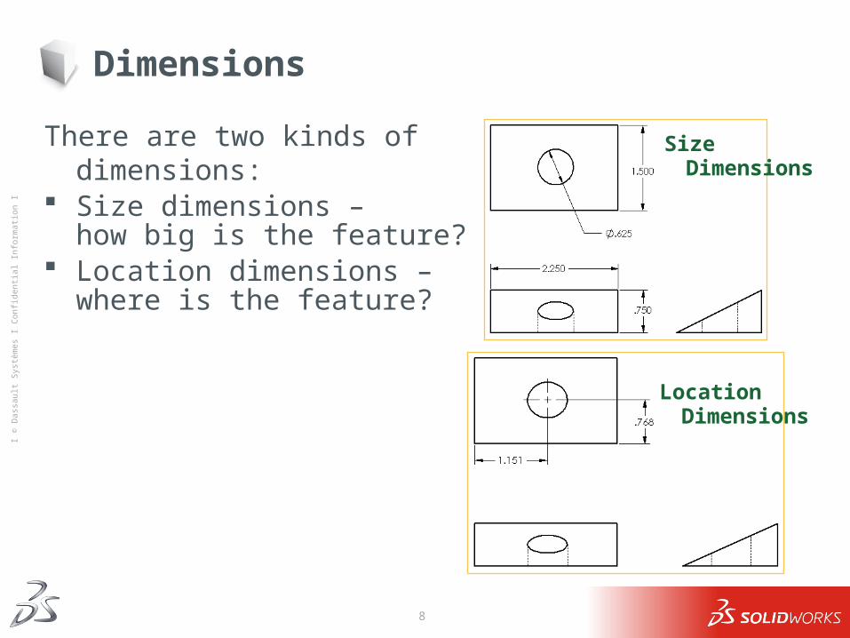
There are two kinds of dimensions: Size dimensions –
how big is the feature? Location dimensions – where is the
feature?
Size Dimensions
Location Dimensions
9
Ι © D
assa
ult S
ystè
mes
Ι Co
nfid
entia
l Inf
orm
atio
n Ι
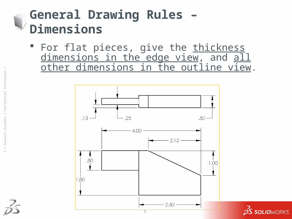
General Drawing Rules – Dimensions
For flat pieces, give the thickness dimensions in the edge view, and all other dimensions in the outline view.
10
Ι © D
assa
ult S
ystè
mes
Ι Co
nfid
entia
l Inf
orm
atio
n Ι
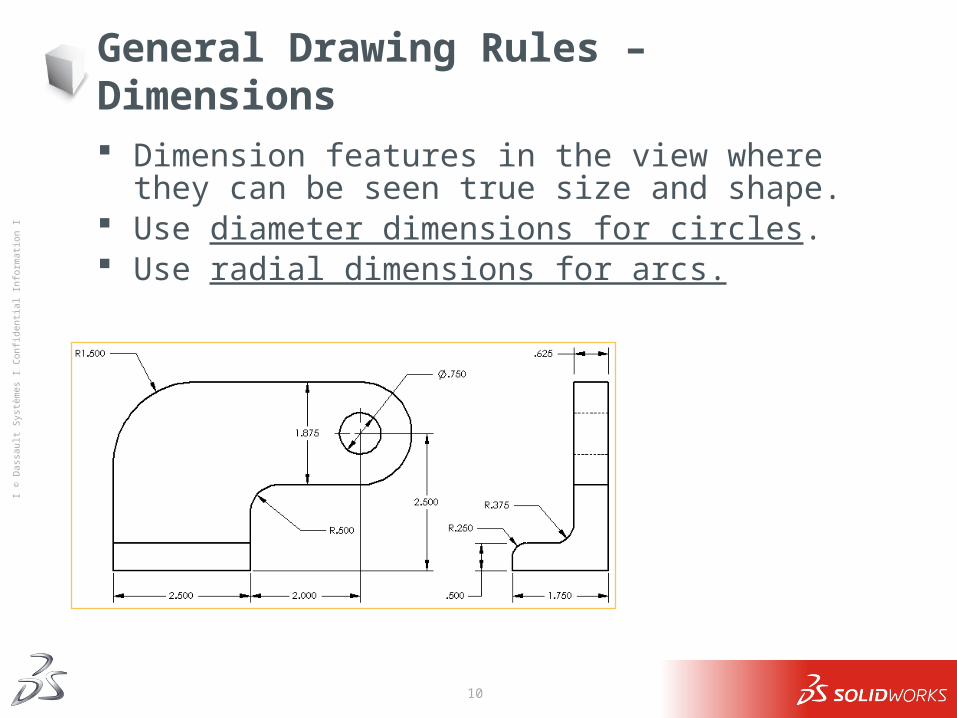
General Drawing Rules – Dimensions
Dimension features in the view where they can be seen true size and shape.
Use diameter dimensions for circles. Use radial dimensions for arcs.
11
Ι © D
assa
ult S
ystè
mes
Ι Co
nfid
entia
l Inf
orm
atio
n Ι
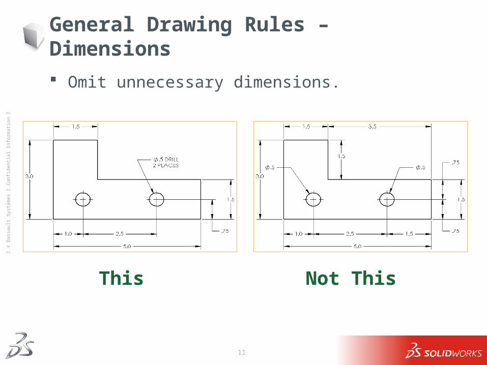
General Drawing Rules – Dimensions
Omit unnecessary dimensions.
This Not This
12
Ι © D
assa
ult S
ystè
mes
Ι Co
nfid
entia
l Inf
orm
atio
n Ι
Dimension Guidelines – Appearance
Place dimensions away from the profile lines. Allow space between individual dimensions. A gap must exist between the profile lines and the extension lines. The size and style of leader line, text, and arrows should be
consistent throughout the drawing. Display only the number of decimal places required for
manufacturing precision. Neatness counts!
13
Ι © D
assa
ult S
ystè
mes
Ι Co
nfid
entia
l Inf
orm
atio
n Ι
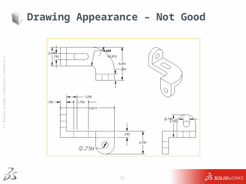
Drawing Appearance – Not Good
14
Ι © D
assa
ult S
ystè
mes
Ι Co
nfid
entia
l Inf
orm
atio
n Ι
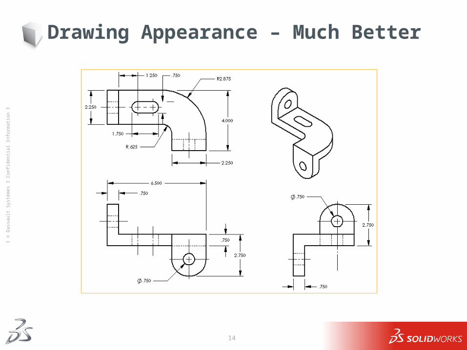
Drawing Appearance – Much Better

15
Ι © D
assa
ult S
ystè
mes
Ι Co
nfid
entia
l Inf
orm
atio
n Ι
16
Ι © D
assa
ult S
ystè
mes
Ι Co
nfid
entia
l Inf
orm
atio
n Ι
What is a Drawing Template?
A Drawing Template is the foundation for drawing information.
A drawing template specifies: Sheet (paper) size Orientation - Landscape or Portrait Sheet Format Borders Title block Data forms and tables such as bill of materials or revision history
17
Ι © D
assa
ult S
ystè
mes
Ι Co
nfid
entia
l Inf
orm
atio
n Ι
Drawing Templates Choices in SolidWorks
Standard SolidWorks drawing template Tutorial drawing template Custom template No template
18
Ι © D
assa
ult S
ystè
mes
Ι Co
nfid
entia
l Inf
orm
atio
n Ι
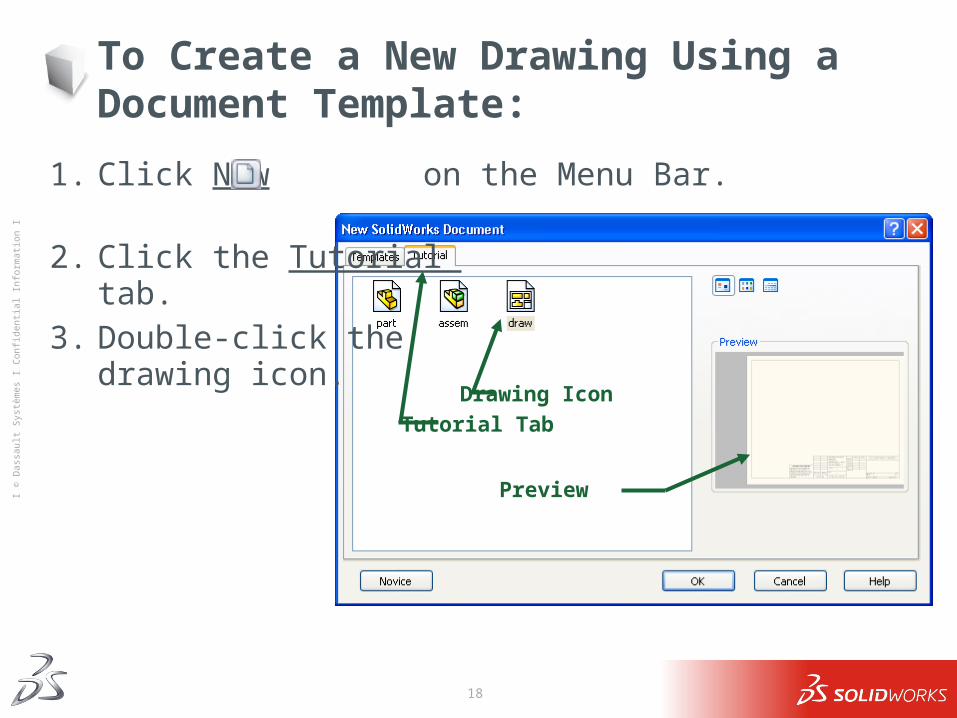
To Create a New Drawing Using a Document Template:
1. Click New on the Menu Bar.
2. Click the Tutorial tab.
3. Double-click the drawing icon.
Tutorial Tab
Drawing Icon
Preview
19
Ι © D
assa
ult S
ystè
mes
Ι Co
nfid
entia
l Inf
orm
atio
n Ι
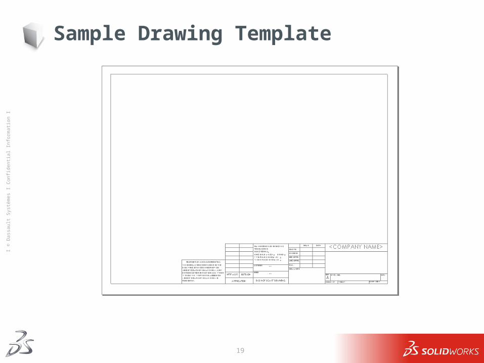
Sample Drawing Template
20
Ι © D
assa
ult S
ystè
mes
Ι Co
nfid
entia
l Inf
orm
atio
n Ι
Edit Sheet vs. Edit Sheet Format
There are two modes in the drawing: Edit Sheet
This is the mode you use to make detailed drawings Used 99+% of the time Add or modify views Add or modify dimensions Add or modify text notes
Edit Sheet Format Change the title block size and text headings Change the border Incorporate a company logo Add standard text that appears on every drawing
21
Ι © D
assa
ult S
ystè
mes
Ι Co
nfid
entia
l Inf
orm
atio
n Ι
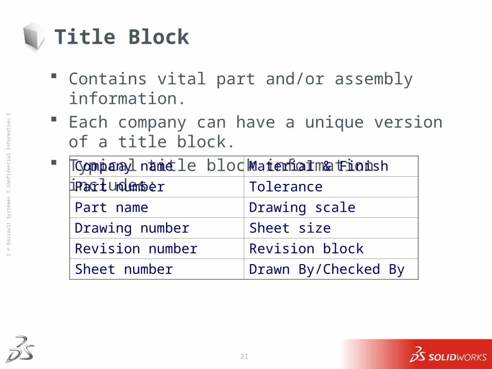
Title Block
Contains vital part and/or assembly information. Each company can have a unique version of a title block. Typical title block information includes:
Company name Material & Finish
Part number Tolerance
Part name Drawing scale
Drawing number Sheet size
Revision number Revision block
Sheet number Drawn By/Checked By
22
Ι © D
assa
ult S
ystè
mes
Ι Co
nfid
entia
l Inf
orm
atio
n Ι
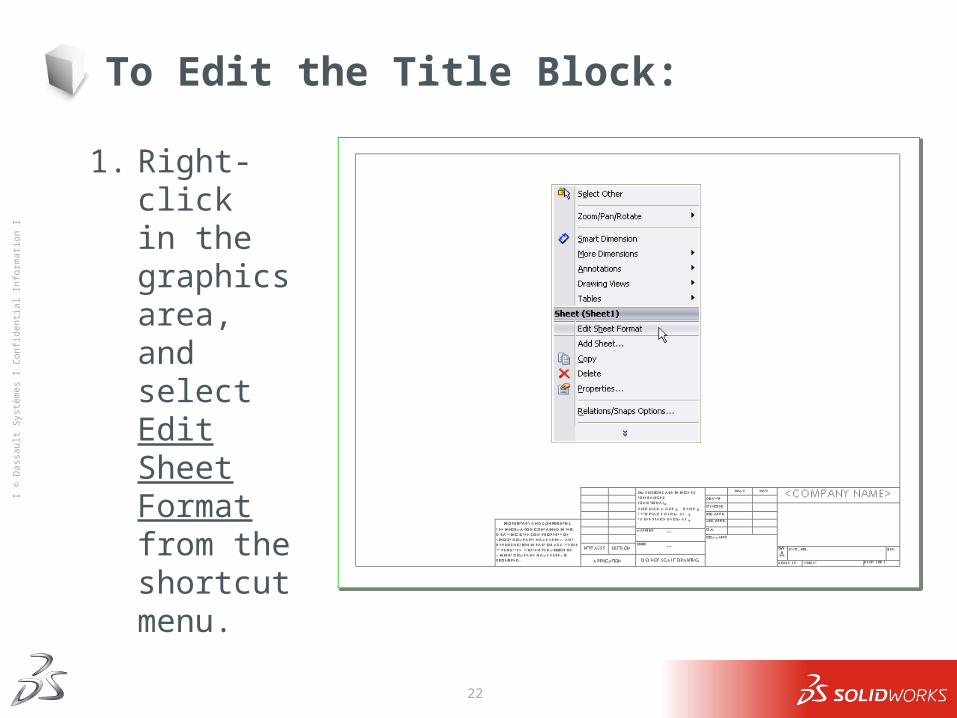
To Edit the Title Block:
1. Right-click in the graphics area, and select Edit Sheet Format from the shortcut menu.
23
Ι © D
assa
ult S
ystè
mes
Ι Co
nfid
entia
l Inf
orm
atio
n Ι
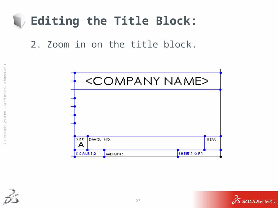
Editing the Title Block:
2. Zoom in on the title block.
24
Ι © D
assa
ult S
ystè
mes
Ι Co
nfid
entia
l Inf
orm
atio
n Ι
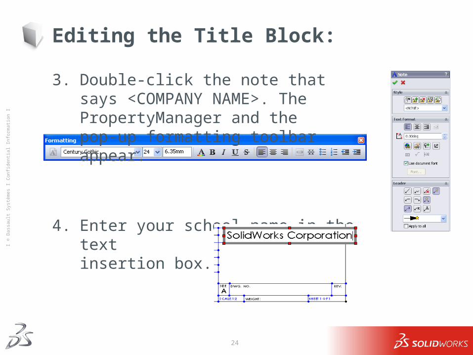
Editing the Title Block:
3. Double-click the note that says <COMPANY NAME>. The PropertyManager and the pop-up formatting toolbar appear.
4. Enter your school name in the text insertion box.
25
Ι © D
assa
ult S
ystè
mes
Ι Co
nfid
entia
l Inf
orm
atio
n Ι
Editing the Title Block:
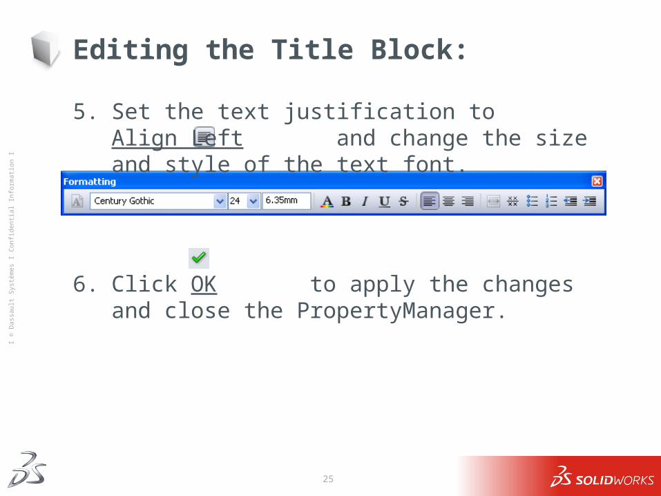
5. Set the text justification toAlign Left and change the size and style of the text font.
6. Click OK to apply the changes and close the PropertyManager.
26
Ι © D
assa
ult S
ystè
mes
Ι Co
nfid
entia
l Inf
orm
atio
n Ι
Editing the Title Block:
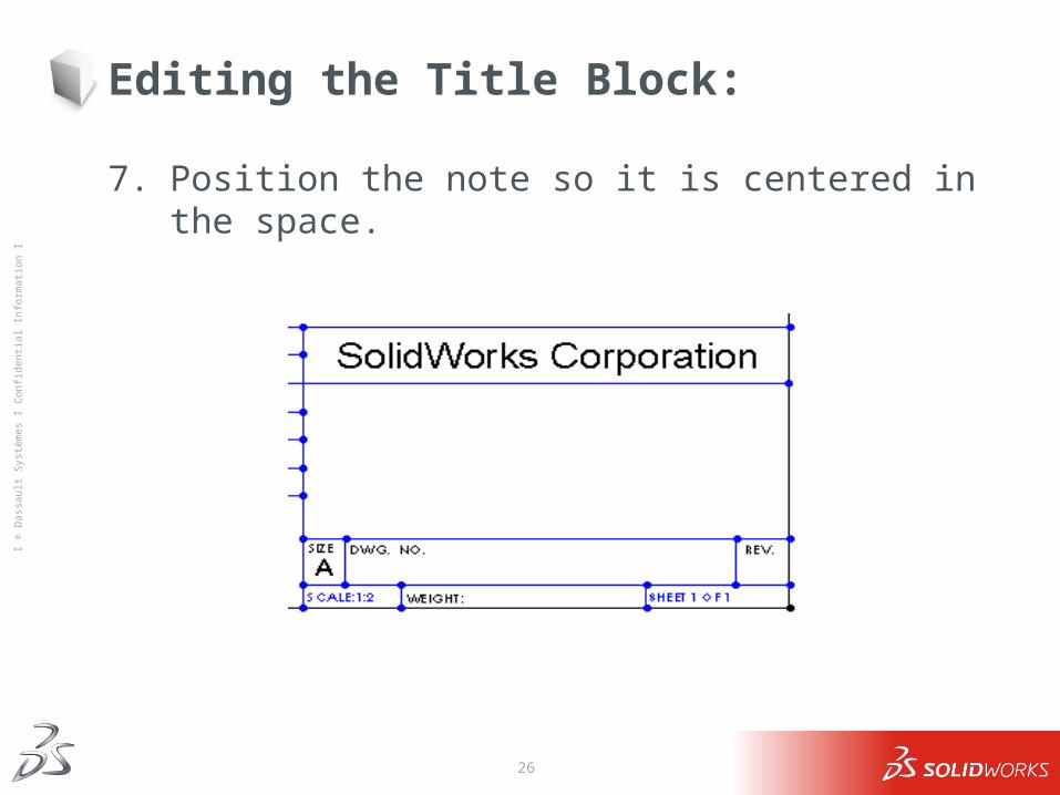
7. Position the note so it is centered in the space.
27
Ι © D
assa
ult S
ystè
mes
Ι Co
nfid
entia
l Inf
orm
atio
n Ι
Customizing the Part Name
Advanced Topic The name of the part or assembly shown on the drawing changes
with every new drawing. It is not very efficient to have to edit the sheet format and the title
block each time you make a new drawing. It would be nice if the title block would automatically be filled in
with the name of the part or assembly that is shown on the drawing.
This can be done.
28
Ι © D
assa
ult S
ystè
mes
Ι Co
nfid
entia
l Inf
orm
atio
n Ι
Editing the Part Name:
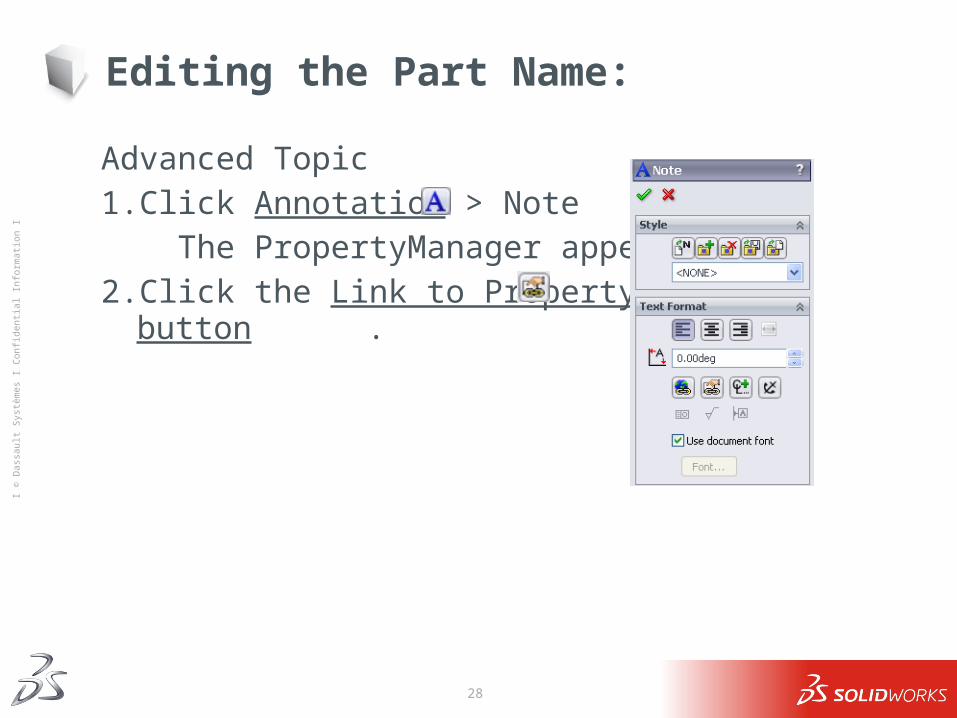
Advanced Topic1. Click Annotation > Note . The PropertyManager appears.2. Click the Link to Property button .
29
Ι © D
assa
ult S
ystè
mes
Ι Co
nfid
entia
l Inf
orm
atio
n Ι
Editing the Part Name:
Advanced Topic
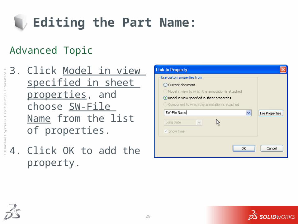
3. Click Model in view specified in sheet properties, and choose SW-File Name from the list of properties.
4. Click OK to add the property.
30
Ι © D
assa
ult S
ystè
mes
Ι Co
nfid
entia
l Inf
orm
atio
n Ι
Editing the Part Name:
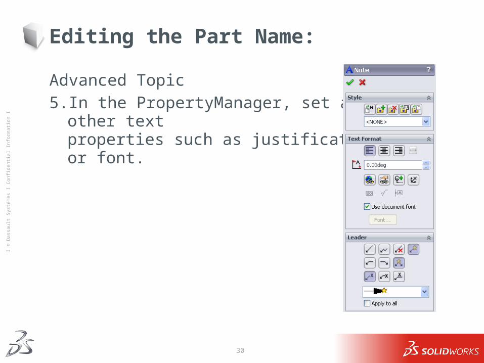
Advanced Topic5. In the PropertyManager, set any other text
properties such as justification, or font.
31
Ι © D
assa
ult S
ystè
mes
Ι Co
nfid
entia
l Inf
orm
atio
n Ι
Editing the Part Name:
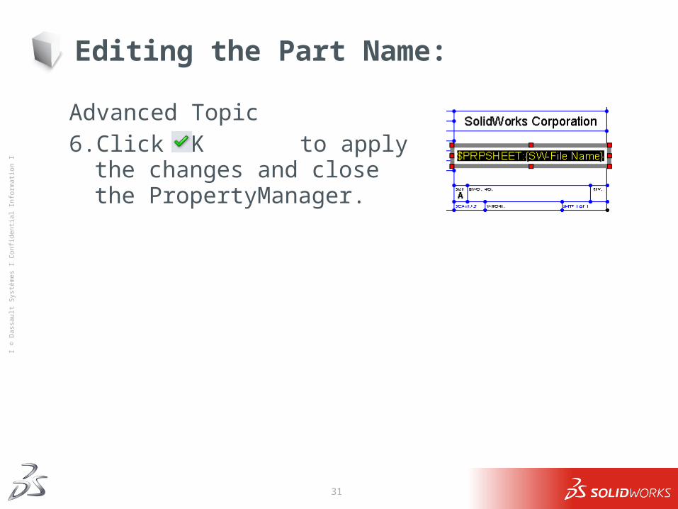
Advanced Topic6. Click OK to apply the changes and
close the PropertyManager.
32
Ι © D
assa
ult S
ystè
mes
Ι Co
nfid
entia
l Inf
orm
atio
n Ι
Advanced Topic
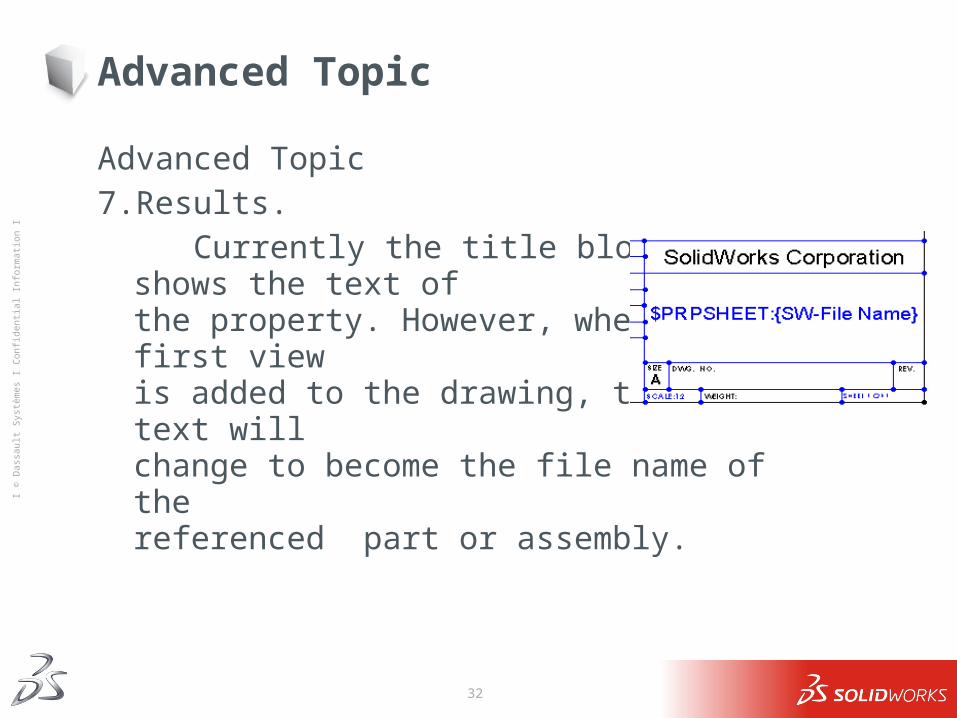
Advanced Topic7. Results. Currently the title block shows the text of
the property. However, when the first view is added to the drawing, that text will change to become the file name of the referenced part or assembly.
33
Ι © D
assa
ult S
ystè
mes
Ι Co
nfid
entia
l Inf
orm
atio
n Ι
Switching to Edit Sheet Mode:
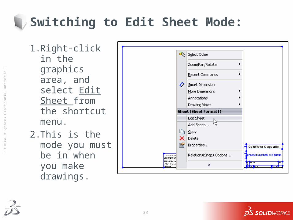
1. Right-click in the graphics area, and select Edit Sheet from the shortcut menu.
2. This is the mode you must be in when you make drawings.
34
Ι © D
assa
ult S
ystè
mes
Ι Co
nfid
entia
l Inf
orm
atio
n Ι
Detailing Options
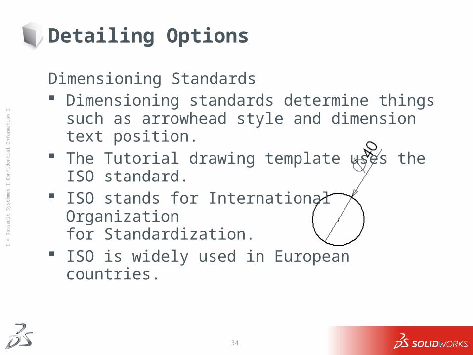
Dimensioning Standards Dimensioning standards determine things such as arrowhead style
and dimension text position. The Tutorial drawing template uses the ISO standard. ISO stands for International Organization
for Standardization. ISO is widely used in European
countries.
35
Ι © D
assa
ult S
ystè
mes
Ι Co
nfid
entia
l Inf
orm
atio
n Ι
Detailing Options
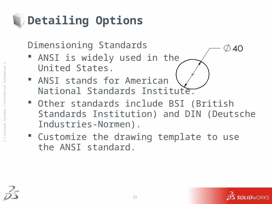
Dimensioning Standards ANSI is widely used in the
United States. ANSI stands for American
National Standards Institute. Other standards include BSI (British Standards Institution) and DIN
(Deutsche Industries-Normen). Customize the drawing template to use the ANSI standard.
36
Ι © D
assa
ult S
ystè
mes
Ι Co
nfid
entia
l Inf
orm
atio
n Ι
Detailing Options
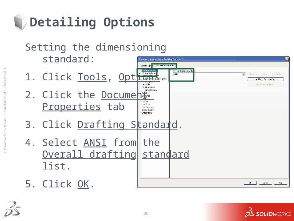
Setting the dimensioning standard:
1. Click Tools, Options.
2. Click the Document Properties tab
3. Click Drafting Standard.
4. Select ANSI from the Overall drafting standard list.
5. Click OK.
37
Ι © D
assa
ult S
ystè
mes
Ι Co
nfid
entia
l Inf
orm
atio
n Ι
Detailing Options
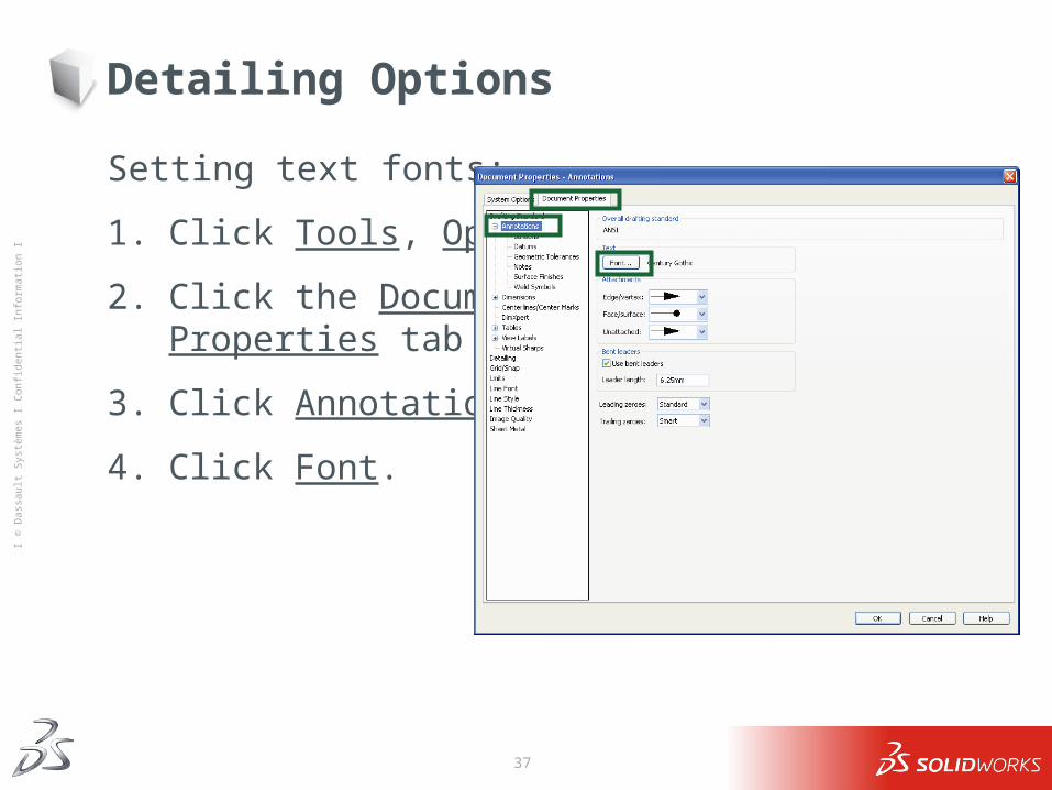
Setting text fonts:
1. Click Tools, Options.
2. Click the Document Properties tab
3. Click Annotations.
4. Click Font.
38
Ι © D
assa
ult S
ystè
mes
Ι Co
nfid
entia
l Inf
orm
atio
n Ι
Detailing Options
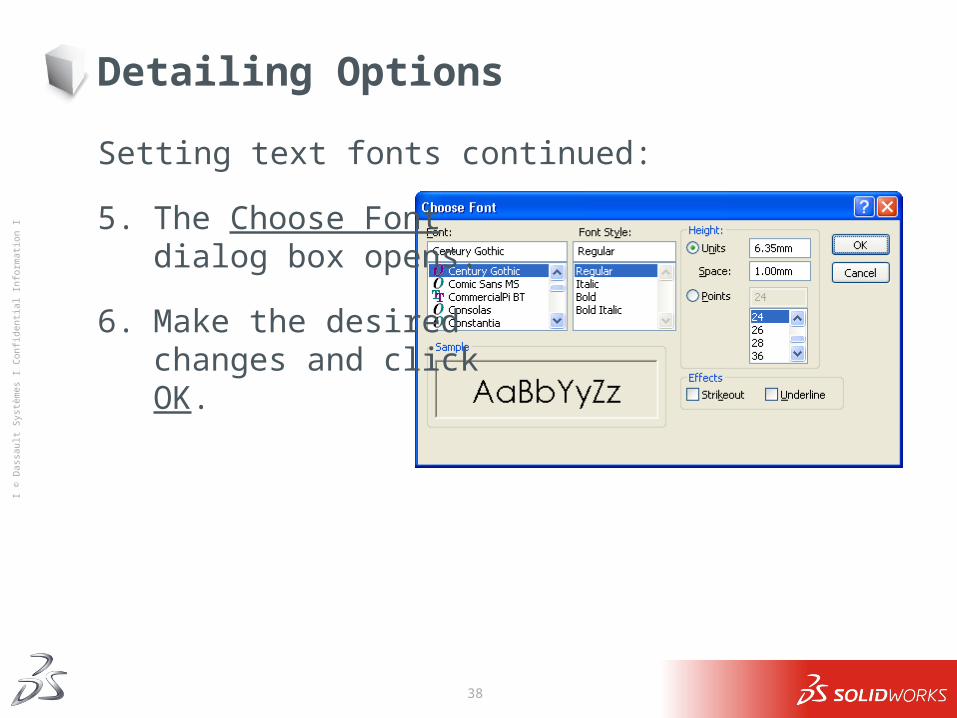
Setting text fonts continued:
5. The Choose Font dialog box opens.
6. Make the desired changes and click OK.
39
Ι © D
assa
ult S
ystè
mes
Ι Co
nfid
entia
l Inf
orm
atio
n Ι
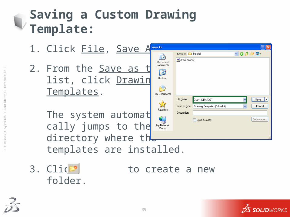
Saving a Custom Drawing Template:
1. Click File, Save As...
2. From the Save as type: list, click Drawing Templates.
The system automati-cally jumps to the directory where the templates are installed.
3. Click to create a new folder.
40
Ι © D
assa
ult S
ystè
mes
Ι Co
nfid
entia
l Inf
orm
atio
n Ι
Saving a Custom Drawing Template:
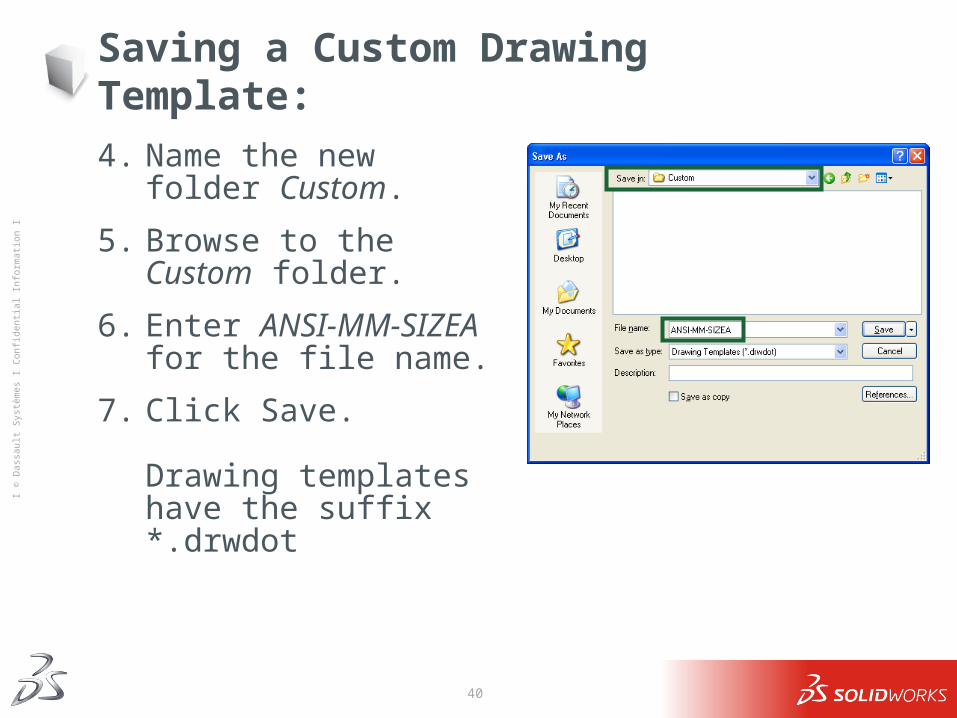
4. Name the new folder Custom.
5. Browse to the Custom folder.
6. Enter ANSI-MM-SIZEA for the file name.
7. Click Save.
Drawing templates have the suffix *.drwdot
41
Ι © D
assa
ult S
ystè
mes
Ι Co
nfid
entia
l Inf
orm
atio
n Ι
Creating a Drawing – General Procedure
1. Open the part or assembly you wish to detail.
2. Open a new drawing of the desired size.
3. Add views: usually three standard views plus any specialized views such as detail, auxiliary, or section views.
4. Insert the dimensions and arrange the dimensions on the drawing.
5. Add additional sheets, views and/or notes if required.
42
Ι © D
assa
ult S
ystè
mes
Ι Co
nfid
entia
l Inf
orm
atio
n Ι
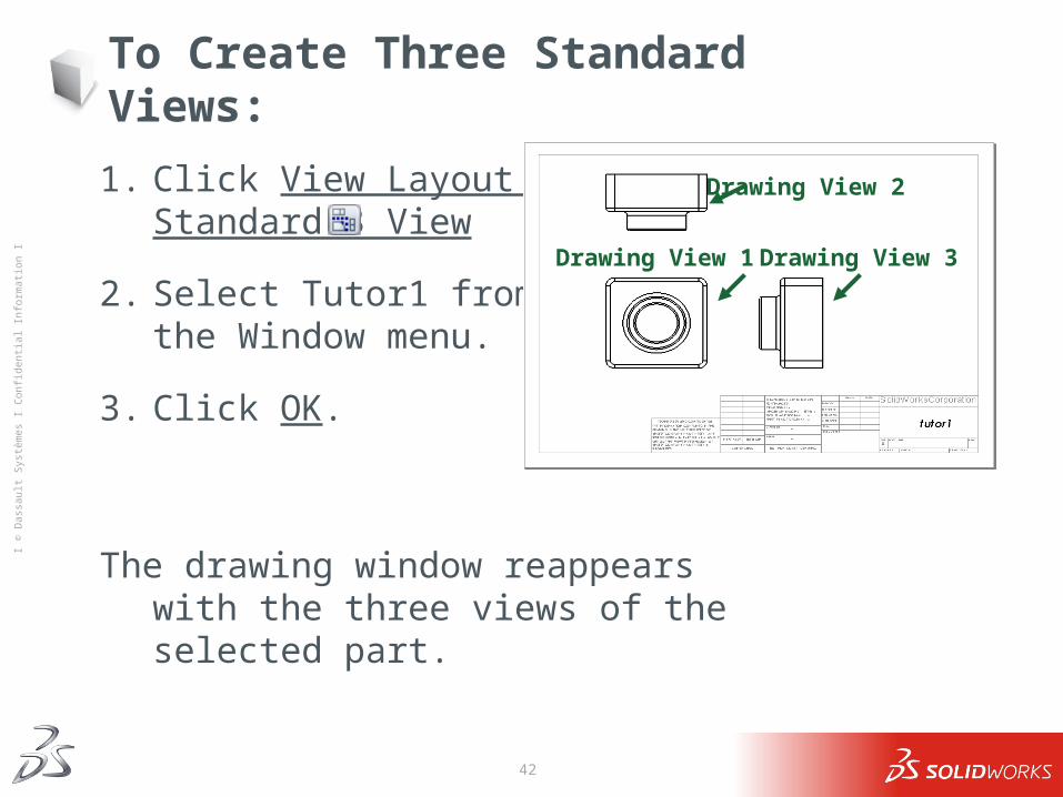
To Create Three Standard Views:
1. Click View Layout > Standard 3 View .
2. Select Tutor1 from the Window menu.
3. Click OK.
The drawing window reappears with the three views of the selected part.
Drawing View 2
Drawing View 1 Drawing View 3
43
Ι © D
assa
ult S
ystè
mes
Ι Co
nfid
entia
l Inf
orm
atio
n Ι
Working with Drawing Views
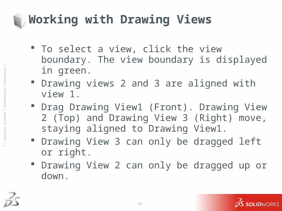
To select a view, click the view boundary. The view boundary is displayed in green.
Drawing views 2 and 3 are aligned with view 1. Drag Drawing View1 (Front). Drawing View 2 (Top) and Drawing
View 3 (Right) move, staying aligned to Drawing View1. Drawing View 3 can only be dragged left or right. Drawing View 2 can only be dragged up or down.
44
Ι © D
assa
ult S
ystè
mes
Ι Co
nfid
entia
l Inf
orm
atio
n Ι
Working with Drawing Views
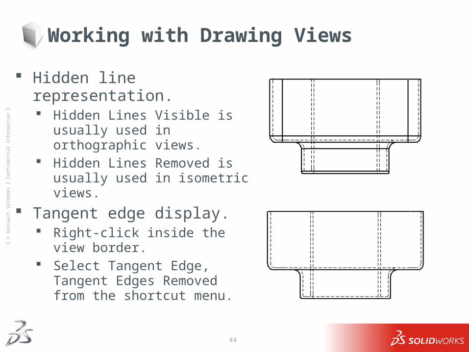
Hidden line representation. Hidden Lines Visible is usually used in
orthographic views. Hidden Lines Removed is usually used in
isometric views. Tangent edge display.
Right-click inside the view border. Select Tangent Edge, Tangent Edges
Removed from the shortcut menu.
45
Ι © D
assa
ult S
ystè
mes
Ι Co
nfid
entia
l Inf
orm
atio
n Ι
Dimensioning Drawings
The dimensions used to create the part can be imported into the drawing.
Dimensions can be added manually using the Smart Dimension tool .
Associativity
Changing the values of imported dimensions will change the part.
You cannot change the values of manually inserted dimensions.
46
Ι © D
assa
ult S
ystè
mes
Ι Co
nfid
entia
l Inf
orm
atio
n Ι
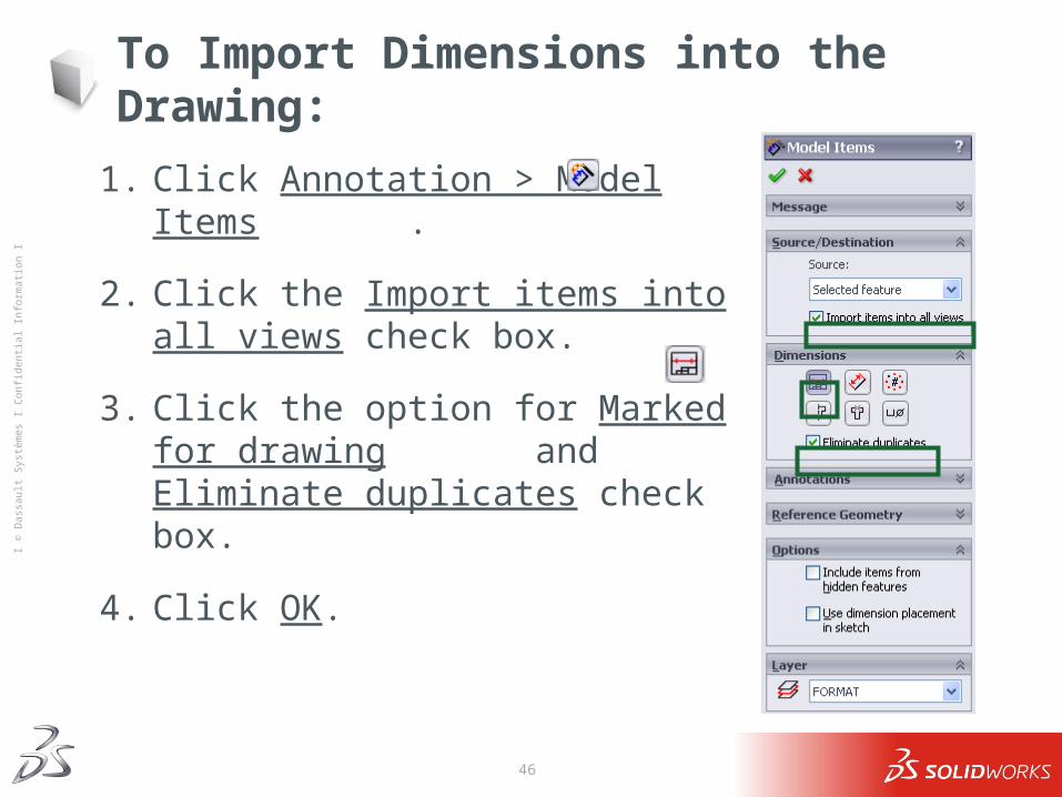
To Import Dimensions into the Drawing:
1. Click Annotation > Model Items .
2. Click the Import items into all views check box.
3. Click the option for Marked for drawing and Eliminate duplicates check box.
4. Click OK.
47
Ι © D
assa
ult S
ystè
mes
Ι Co
nfid
entia
l Inf
orm
atio
n Ι
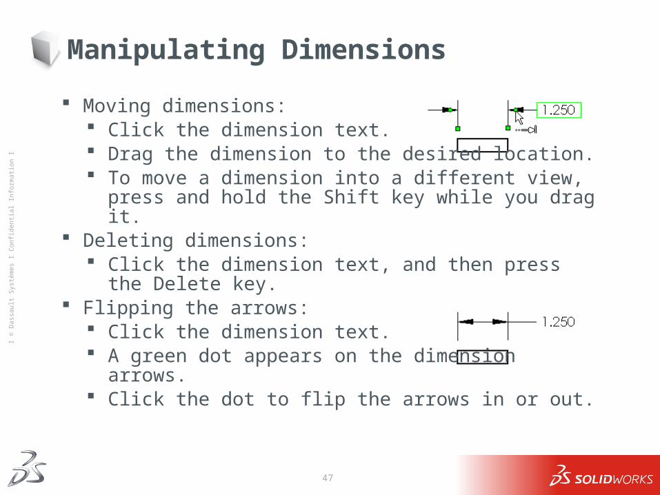
Manipulating Dimensions
Moving dimensions: Click the dimension text. Drag the dimension to the desired location. To move a dimension into a different view, press and hold
the Shift key while you drag it. Deleting dimensions:
Click the dimension text, and then press the Delete key. Flipping the arrows:
Click the dimension text. A green dot appears on the dimension
arrows. Click the dot to flip the arrows in or out.
48
Ι © D
assa
ult S
ystè
mes
Ι Co
nfid
entia
l Inf
orm
atio
n Ι
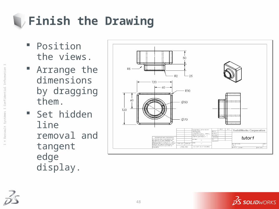
Finish the Drawing
Position the views. Arrange the
dimensions by dragging them.
Set hidden line removal and tangent edge display.
49
Ι © D
assa
ult S
ystè
mes
Ι Co
nfid
entia
l Inf
orm
atio
n Ι
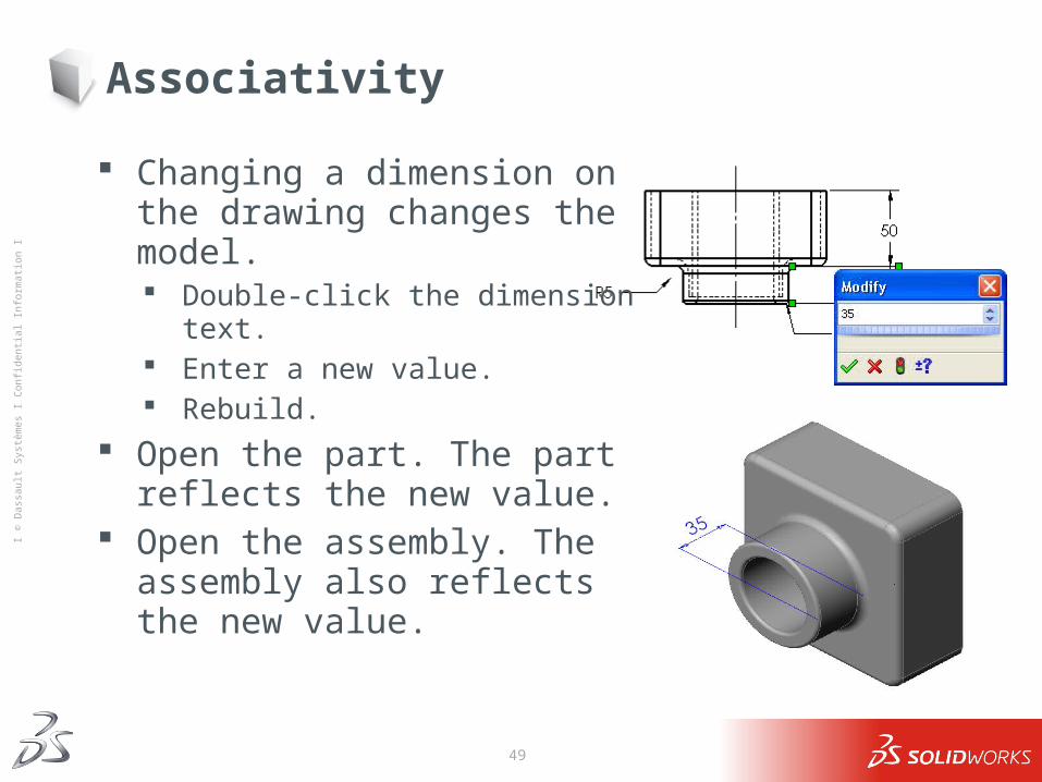
Associativity
Changing a dimension on the drawing changes the model. Double-click the dimension text. Enter a new value. Rebuild.
Open the part. The part reflects the new value.
Open the assembly. The assembly also reflects the new value.
50
Ι © D
assa
ult S
ystè
mes
Ι Co
nfid
entia
l Inf
orm
atio
n Ι
Multi-sheet Drawings
Drawings can contain more than one sheet. The first drawing sheet contains Tutor1. The second drawing sheet contains the Tutor assembly. Use the B-size landscape (11” x 17”) drawing Sheet Format. Add 3 standard views. Add an Isometric view of the assembly. The Isometric view is a
model view.
51
Ι © D
assa
ult S
ystè
mes
Ι Co
nfid
entia
l Inf
orm
atio
n Ι
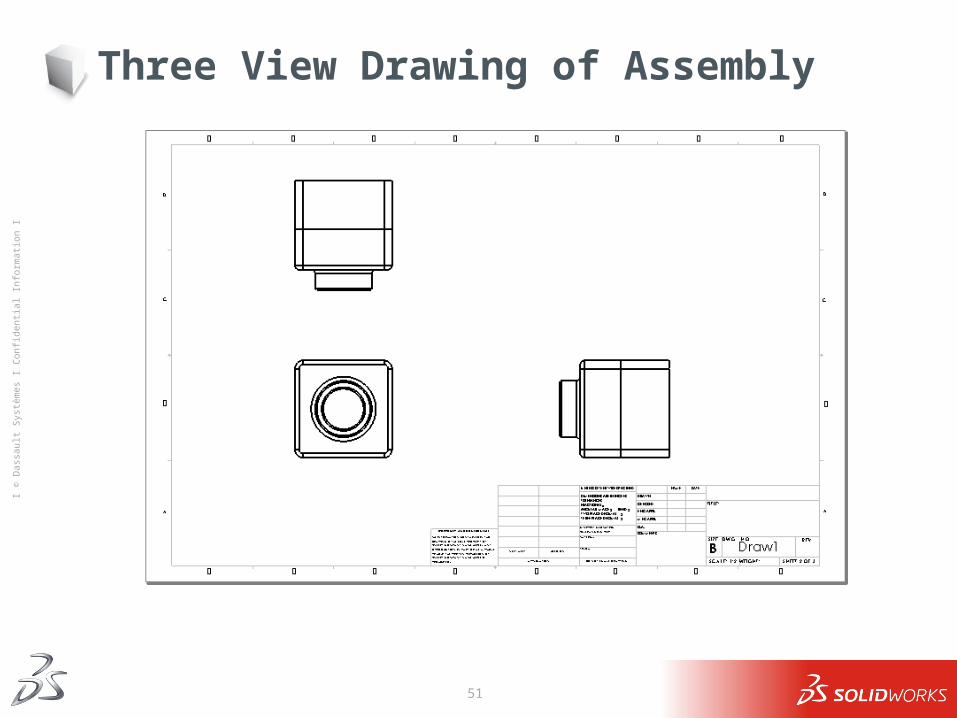
Three View Drawing of Assembly
52
Ι © D
assa
ult S
ystè
mes
Ι Co
nfid
entia
l Inf
orm
atio
n Ι
Model Views
A model view shows the part or assembly in a specific orientation. Examples of model views are:
Standard Views such as Front, Top or Isometric view. User-defined view orientations that were created in the part or assembly. The current view in a part or assembly.
53
Ι © D
assa
ult S
ystè
mes
Ι Co
nfid
entia
l Inf
orm
atio
n Ι
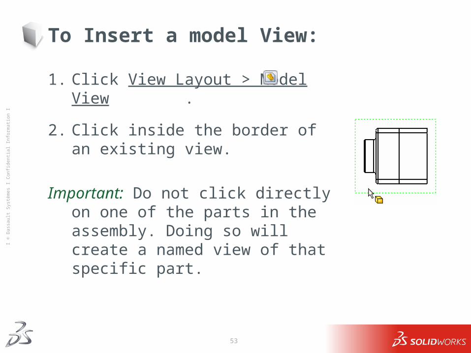
To Insert a model View:
1. Click View Layout > Model View .
2. Click inside the border of an existing view.
Important: Do not click directly on one of the parts in the assembly. Doing so will create a named view of that specific part.
54
Ι © D
assa
ult S
ystè
mes
Ι Co
nfid
entia
l Inf
orm
atio
n Ι
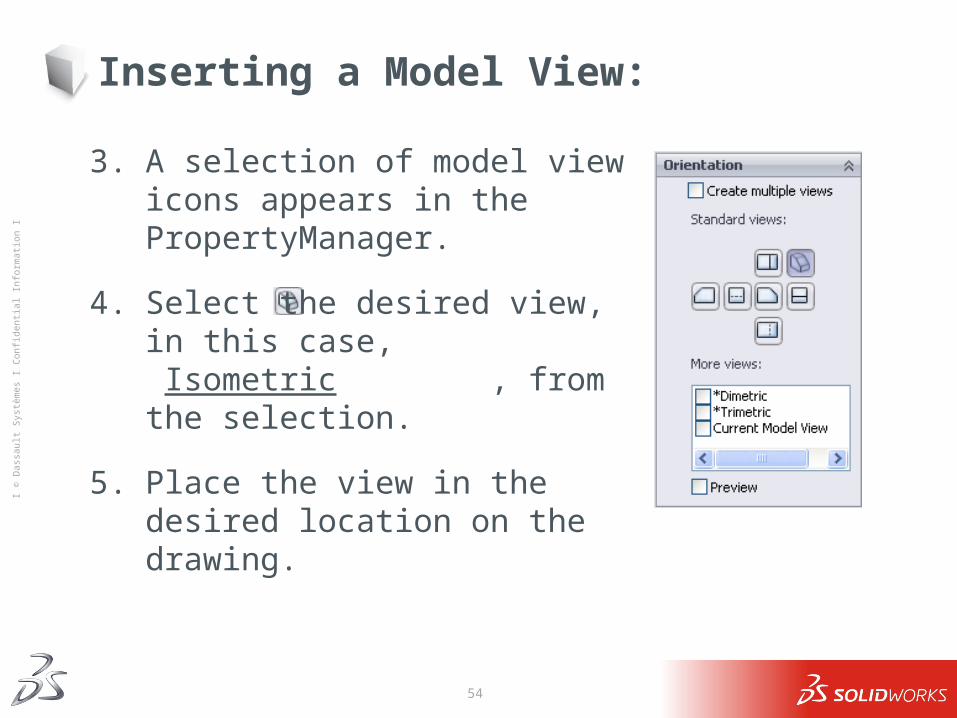
Inserting a Model View:
3. A selection of model view icons appears in the PropertyManager.
4. Select the desired view, in this case, Isometric , from the selection.
5. Place the view in the desired location on the drawing.
55
Ι © D
assa
ult S
ystè
mes
Ι Co
nfid
entia
l Inf
orm
atio
n Ι
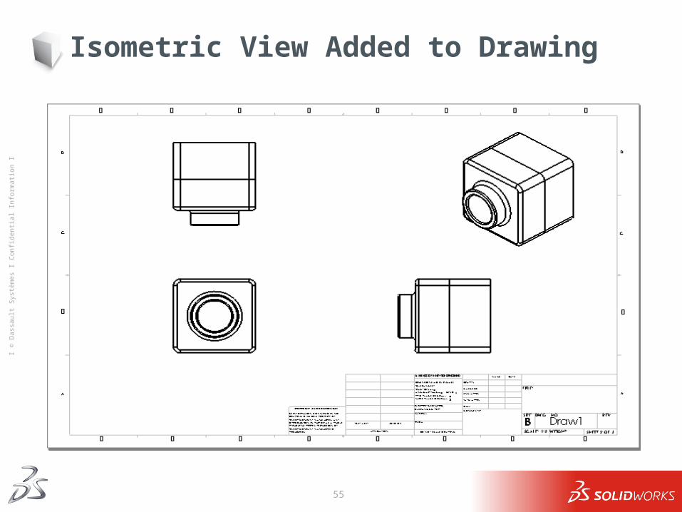
Isometric View Added to Drawing
56
Ι © D
assa
ult S
ystè
mes
Ι Co
nfid
entia
l Inf
orm
atio
n Ι
Specialized Views
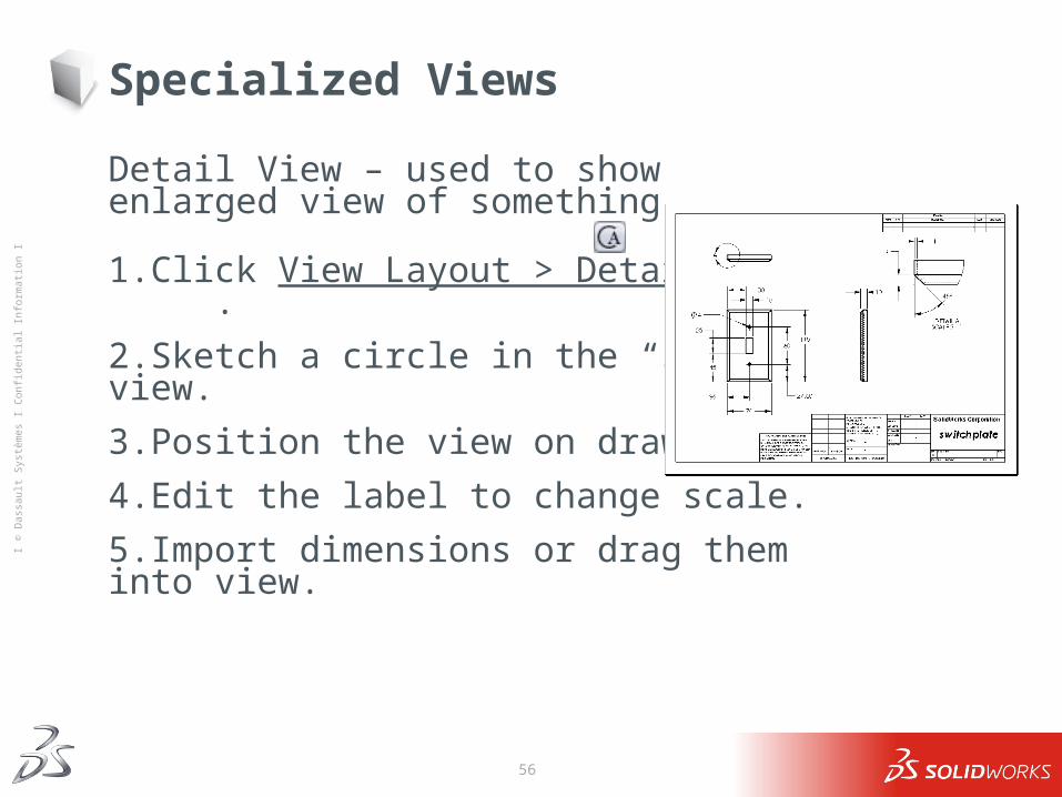
Detail View – used to show enlarged view of something.
1.Click View Layout > Detail View .
2.Sketch a circle in the “source” view.
3.Position the view on drawing.
4.Edit the label to change scale.
5.Import dimensions or drag them into view.
57
Ι © D
assa
ult S
ystè
mes
Ι Co
nfid
entia
l Inf
orm
atio
n Ι
Specialized Views
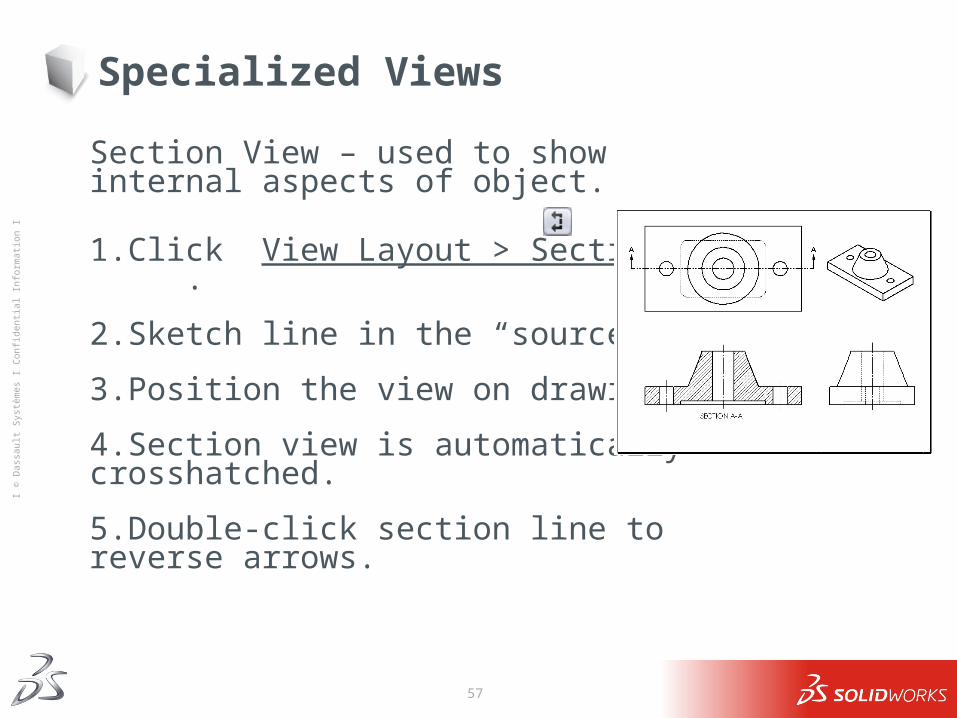
Section View – used to show internal aspects of object.
1.Click View Layout > Section View .
2.Sketch line in the “source” view.
3.Position the view on drawing.
4.Section view is automatically crosshatched.
5.Double-click section line to reverse arrows.
![Mathématiques Appliquées et Aéronautique - [SMAI]smai.emath.fr/documents/Stoufflet.pdf · T34 DASSAULT T5 LATECOERE Fin DASSAULT T12 DASSAULT ... < 6 hours on 32 processors IBM-SP](https://img.pdfslide.tips/doc/110x75/5b819b427f8b9a7b6f8cbe15/mathematiques-appliquees-et-aeronautique-smaismaiemathfrdocuments-.jpg)