Embed Size (px)
Citation preview

HIL COMPATIBLE ENGINE MODELS FOR DUAL FUEL APPLICATIONS
Johann KRAMMER1, Prof. Tomaz Katrasnik2
1 AVL List GmbH, Graz, Austria
2 Univ. of Ljubljana, Slovenia
E-mails: [email protected], [email protected]
ABSTRACT
More and more, alternative fuels, fuel mixtures and dual-fuel engines are gaining in
importance. This means a huge challenge to thermodynamic modeling of combustion and
species transport. The computational performance is reached by an optimized filling and
emptying approach applying tailored models for in-cylinder combustion and species transport
in the gas path. The impact of the thermodynamic characteristics induced by the different
fuels is described by an appropriate set of transport equations in combination with specifically
prepared property databases. The accuracy of a lumped fuel approach is compared for a six,
three and one species transport. The simulations are performed with a 6 cylinder medium
speed engine. The real-time factor of this engine is in the range of 0.2 for all species transport
approaches, what enables this method to support HiL based function development and
calibration.
INTRODUCTION
Methanol, ethanol and renewable biofuels as well as blends of it are gaining importance as
sources of energy. Also attempts to exploit shale gas have been made. The characteristic of
shale gas with methane as one of its major components makes it especially attractive for use
in internal combustion engines. Because of these trends we are facing an increasing number of
dual fuel approaches, especially for stationary, marine, locomotive but also truck applications.
There are two basic design concepts for dual fuel engines, following a recent technology
review presented by Shah et al. [1]. Both concepts are based on a typical compression ignited
direct injection Diesel engine where gas is additionally injected either directly into the Diesel
spray in the cylinder at higher pressure or at low pressure into the intake port featuring a
premixed homogeneous air gas mixture. Properly designed dual fuel engines can achieve
superior full-load fuel efficiency and BMEP than spark ignited engines and can achieve a
substantial reduction in NOx and particulate matter emissions compared to compression
ignited engines but they need a sophisticated control system. The combustion of dual fuel
fired Diesel engines deviates decisively from pure Diesel engines. For port injected gas
engines and low ratios of Diesel to gaseous fuel, the pilot injected Diesel does not serve as
main energy source but it is supposed to ignite the premixed gas air mixture. Out of this, two
different combustion regimes can be identified. First, a Diesel-like combustion takes places
influenced by spray penetration, droplet breakup, its evaporation, gas air mixture entrainment
and ignition. Here the description of the ignition delay is essential as it deviates in dual fuel
Blucher Engineering ProceedingsSetembro de 2015, Número 1, Volume 2
operation due to different gas properties of the gas air mixture (Liu and Karim[2]). The
second combustion regime is comparable to the one of spark ignited gasoline or gas engines.
The ignition takes place around the Diesel pilot spray cones and a flame front propagates
through the combustion chamber. Here, the description of the flame turbulence is important as
it is influenced by the Diesel spray inducing additional kinetic energy.
For dual fuel engines with port injection of the gaseous fuel, the concentration of the
premixed gas has to be limited to avoid knocking (see Karim and Zhaoda [3]) in the case of
high compression ratios of the engine. This leads to even more complex combustion patterns
as larger amounts of Diesel fuel are injected over a longer period of time causing a
coexistence of inhomogeneous and homogeneous types of combustion. Unlike in port injected
dual fuel engines, in dual fuel engines featuring direct injection of both fuels in the vicinity of
the TDC, the inhomogeneous type of combustion prevails for both fuels (Shah et al. [1]).
However, this type of dual fuel combustion still differs from the pure Diesel-like
inhomogeneous combustion due to distinct mixture preparation characteristics and different
chemical kinetic mechanisms inherent to dual fuel combustion.
A broad variety of phenomenological combustion model approaches can be found from
literature with the attempt to transform the complexity of dual fuel combustion into a simple
set of equations, with respect that it is not purely super-imposing existing models for Diesel
and premixed gas combustion. The interference of the two combustion regimes leads to either
new governing equations or requires at least a thorough re-parameterization of existing
approaches.
The increasing requirements on control development and calibration leads to “model based
development” as a key strategy in the modern development process (Kordon et al. [4]). It is
based on real-time capable, semi-physical engine plant models, drivetrain models run on a
virtual test bed equipped with established automation, data management and monitoring tools.
Focus on the dual fuel combustion model development presented in this paper was on real-
time capability, model accuracy and time for model setup.
In order to efficiently comply with the above requirements an innovative computationally
optimized filling and emptying approach presented in Wurzenberger et al. [5] was used as
modeling basis.
Further addressed in this paper is the species transport and an appropriate treatment of all
mixture properties.
1. MODEL
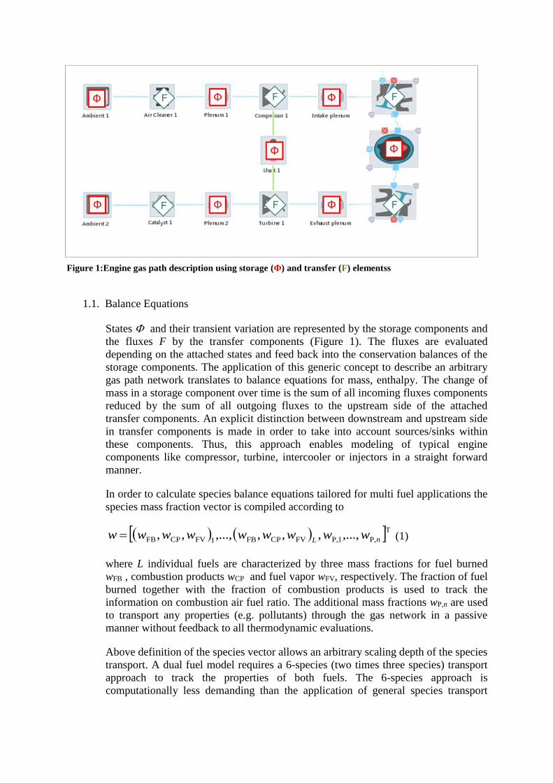
The generic concept of "storage" and "transfer" elements (Merker and Schwarz [6]) is used
for modelling the gas path. These element types are alternatively connected to each other.
Typical examples for storage elements are volumes, cylinders, walls, fuel films or rotating
shafts and for transfer elements compressor, turbine, intercooler, air cleaner, ports, or
restrictions, see Figure 1.
1.1. Balance Equations
States and their transient variation are represented by the storage components and
the fluxes F by the transfer components (Figure 1). The fluxes are evaluated
depending on the attached states and feed back into the conservation balances of the
storage components. The application of this generic concept to describe an arbitrary
gas path network translates to balance equations for mass, enthalpy. The change of
mass in a storage component over time is the sum of all incoming fluxes components
reduced by the sum of all outgoing fluxes to the upstream side of the attached
transfer components. An explicit distinction between downstream and upstream side
in transfer components is made in order to take into account sources/sinks within
these components. Thus, this approach enables modeling of typical engine
components like compressor, turbine, intercooler or injectors in a straight forward
manner.
In order to calculate species balance equations tailored for multi fuel applications the
species mass fraction vector is compiled according to
TP,1P,FVCPFB1FVCPFB ,...,,,,,...,,, nLwwwwwwwww (1)
where L individual fuels are characterized by three mass fractions for fuel burned
wFB , combustion products wCP and fuel vapor wFV, respectively. The fraction of fuel
burned together with the fraction of combustion products is used to track the
information on combustion air fuel ratio. The additional mass fractions wP,n are used
to transport any properties (e.g. pollutants) through the gas network in a passive
manner without feedback to all thermodynamic evaluations.
Above definition of the species vector allows an arbitrary scaling depth of the species
transport. A dual fuel model requires a 6-species (two times three species) transport
approach to track the properties of both fuels. The 6-species approach is
computationally less demanding than the application of general species transport
Figure 1:Engine gas path description using storage (Φ) and transfer (F) elementss
methods (see Wanker et al.[7]) including chemical equilibrium calculation during the
run-time. One important requirement is real-time capability therefore computanional
performance is a decisive factor. Because of this it will also be compared with a 3-
and 1-species approach. A 3-species transport approach can be applied under the
assumption that the influence of varying fuel composition is negligible regarding
combustion product and fuel vapor properties. Thus, only a lumped fuel is
transported and contributions of different fuels are mapped to the species vector
(massfraction burned fuel, combustion ptoducts and fuel vapor) of this lumped fuel.
A1-species transport approach (transport of fuel burned only) can be applied under
the assumption that influences of fuel vapor can be neglected.
The species balance equation is applied in an explicit form for the species mass
fraction. This is given by
I
i
J
j
sjsiDSis wmwm
mdt
dw
1 1
US,,,DS, 111
(2)
where ws represents the mass fraction of species s in the species vector of Eq. (2).
The fractions wDS,i,s of species s belongs to the downstream side of the attached
transfer component in case the corresponding mass flux is positive. For the case of
changed flow directions ( ) the mass fractions are taken from the considered
storage component itself (ws). The same rule for defining the species fractions is
applied for the fluxes going out of the component into the upstream side of the
attached transfer components.
1.2. Medium Properties
The enthalpy equation applies several thermodynamic properties that need to
represent dual (multi) fuel characteristics. The properties of the gas mixture are
evaluated according to
],,[
1
CP,CP,
1
FV,FV,AirAir
Rhux
wxwxwxxL
l
ll
L
l
ll
(3)
where the property x (representing mass specific internal u energy, enthalpy h and
gas constant R) of the overall fluid mixture is composed out of the properties of air
and the mass weighted sums of fuel vapor and combustion products of all involved
fuels, respectively. The mass fraction of air (wAir) is evaluated depending on the
given mass fraction of fuel vapor and combustion products of all L fuels. This is
given by
L
l
l
L
l
l www1
CB,
1
FV,Air 1 (4)
In Eq. (3), the thermodynamic properties of fuel vapor and air are assumed to be
solely dependent on temperature. Thus, they are taken from a database following the
NASA polynomial format. The fluid properties of combustion products are assumed
to depend on temperature, pressure and the excess air ratio from the time when
combustion took place. This excess air ratio CP is evaluated out of the balanced
conservation variables for combustion products and fuel burned. It is given for the
l’th fuel by
ll
ll
lAFw
ww
,stoichFB,
FB,CP,
,CP
(5)
where AFStoich,l represents the stoichiometric air to fuel ratio of the considered fuel.
The thermodynamic properties of the combustion product associated to a specific
fuel are evaluated following an assessment of the corresponding species composition.
Here, a thermodynamic equilibrium is assumed at temperatures above 1700K
(Heywood [8]) and “frozen” composition at temperatures below. Thus, with a given
ratio of C, H, O, N, representing a considered fuel and air mixture and assuming that
combustion products consist of twelve relevant species the combustion product
equilibrium composition is calculated to populate look-up tables in a temperature
range from 200K to 4000K, a pressure range from 1bar to 200bar and an excess air
ratio range between 0.3 and 10000.
The present study applies three individual fuel property tables generated for Diesel
(represented by C10H17) for LPG (65% butane and 35% propane mixture) and
methane (CH4), respectively. The consistency of the multi-fuel relies on the fact that
during run-time individual fuel property tables can be blended based on the actual
fuel composition. The mixture properties of fuel blends are evaluated by mass
weighting of the properties of the individual “pure” fuels. This approach is also
applied for blending combustion products although they rely on equilibrium
calculations. That this approach features nearly perfect coincidence with the general
species transport was proven in a paper from Katrašnik T. And Wurzenberger J.C.
[13]
The 3-species approach transports only species of one lumped fuel. Furthermore,
contributions of different fuels are not constant in different engine components or
different strokes of the cylinders and also not in different dual fuel operating modes.
Since, these effects cannot be traced by the reduced number of transported species, it
is necessary to select in advance an appropriate set of “lumped” single fuel
properties. Here, properties of either “pure” fuels or a particular fuel blend can be
chosen. In general, the errors are even more significant for the properties of fuel
vapor. These inaccuracies apply to the properties of fuel vapor and combustion
products. However it is easily possible to adapt the lower heating value, the
stoichiometric air fuel ratio and also the heat of evaporation to the actual fuel
blending as inflows of both fuels into the cylinder are generally known.
2. RESULTS
The work was performed with the MAN D 0826 LOH 15 turbocharged and intercooled 6
cylinder engine, see Figure 2. The air path topology is assembled out of base library
components that are parameterized with geometry data, manufacture data (e.g. compressor
and turbine) and with the help of the given ROHR data. The application of the latter turned
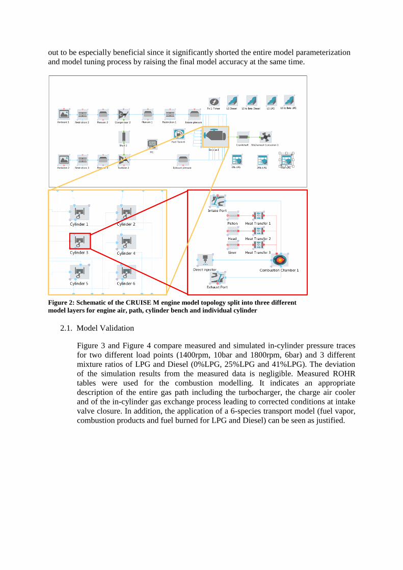
out to be especially beneficial since it significantly shorted the entire model parameterization
and model tuning process by raising the final model accuracy at the same time.
2.1. Model Validation
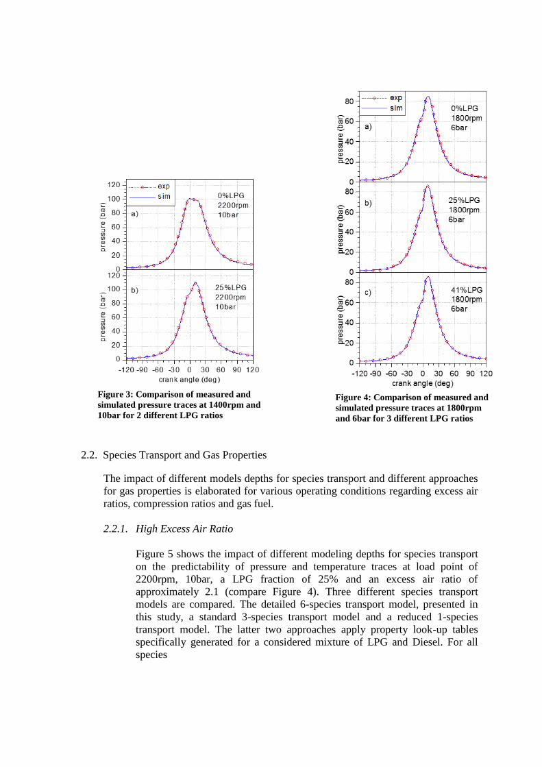
Figure 3 and Figure 4 compare measured and simulated in-cylinder pressure traces
for two different load points (1400rpm, 10bar and 1800rpm, 6bar) and 3 different
mixture ratios of LPG and Diesel (0%LPG, 25%LPG and 41%LPG). The deviation
of the simulation results from the measured data is negligible. Measured ROHR
tables were used for the combustion modelling. It indicates an appropriate
description of the entire gas path including the turbocharger, the charge air cooler
and of the in-cylinder gas exchange process leading to corrected conditions at intake
valve closure. In addition, the application of a 6-species transport model (fuel vapor,
combustion products and fuel burned for LPG and Diesel) can be seen as justified.
Figure 2: Schematic of the CRUISE M engine model topology split into three different
model layers for engine air, path, cylinder bench and individual cylinder
2.2. Species Transport and Gas Properties
The impact of different models depths for species transport and different approaches
for gas properties is elaborated for various operating conditions regarding excess air
ratios, compression ratios and gas fuel.
2.2.1. High Excess Air Ratio
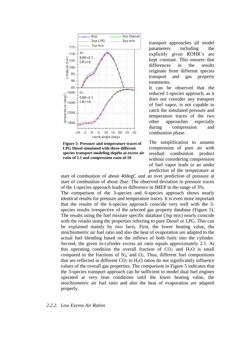
Figure 5 shows the impact of different modeling depths for species transport
on the predictability of pressure and temperature traces at load point of
2200rpm, 10bar, a LPG fraction of 25% and an excess air ratio of
approximately 2.1 (compare Figure 4). Three different species transport
models are compared. The detailed 6-species transport model, presented in
this study, a standard 3-species transport model and a reduced 1-species
transport model. The latter two approaches apply property look-up tables
specifically generated for a considered mixture of LPG and Diesel. For all
species
Figure 3: Comparison of measured and
simulated pressure traces at 1400rpm and
10bar for 2 different LPG ratios
Figure 4: Comparison of measured and
simulated pressure traces at 1800rpm
and 6bar for 3 different LPG ratios
transport approaches all model
parameters including the
explicitly given ROHR’s are
kept constant. This ensures that
differences in the results
originate from different species
transport and gas property
treatments.
It can be observed that the
reduced 1-species approach, as it
does not consider any transport
of fuel vapor, is not capable to
catch the simulated pressure and
temperature traces of the two
other approaches especially
during compression and
combustion phase.
The simplification to assume
compression of pure air with
residual combustion product
without considering compression
of fuel vapor leads to an under
prediction of the temperature at
start of combustion of about 40degC and an over prediction of pressure at
start of combustion of about 2bar. The observed deviation in pressure traces
of the 1-species approach leads to difference in IMEP in the range of 3%.
The comparison of the 3-species and 6-species approach shows nearly
identical results for pressure and temperature traces. It is even more important
that the results of the 6-species approach coincide very well with the 3-
species results irrespective of the selected gas property database (Figure 5).
The results using the fuel mixture specific database (3sp mix) nearly coincide
with the results using the properties referring to pure Diesel or LPG. This can
be explained mainly by two facts. First, the lower heating value, the
stoichiometric air fuel ratio and also the heat of evaporation are adapted to the
actual fuel blending based on the inflows of both fuels into the cylinder.
Second, the given in-cylinder excess air ratio equals approximately 2.1. At
this operating condition the overall fraction of CO2 and H2O is small
compared to the fractions of N2, and O2. Thus, different fuel compositions
that are reflected in different CO2 to H2O ratios do not significantly influence
values of the overall gas properties. The comparison in Figure 5 indicates that
the 3-species transport approach can be sufficient to model dual fuel engines
operated at very lean conditions until the lower heating value, the
stoichiometric air fuel ratio and also the heat of evaporation are adapted
properly.
2.2.2. Low Excess Air Ratios
Figure 5: Pressure and temperature traces of
LPG Diesel simulated with three different
species transport modeling depths at excess air
ratio of 2.1 and compression ratio of 18
Operating conditions with lower
excess air ratios are simulated to
ensure a more comprehensive
analysis of the influence of
different species transport
approaches and the influence of
different gas property databases.
Furthermore, in addition to the
Diesel-LPG blend also a Diesel-
CH4 blend is investigated. This is
motivated by two facts. First, it
is expected that the availability
of CH4 as fuel will increase as
described in the introduction.
Second, the differences in fuel
vapor and combustion product
properties between CH4 and
Diesel are more significant than
between LPG and Diesel.
Analyses are performed for two
excess air ratios of
approximately 1.45 and 1.25.
The latter value typically
corresponds to the lower end of
the excess air ratio characteristic
applied in modern engines
featuring inhomogeneous
combustion. The investigation is
made for an engine speed of
2200rpm. This is motivated by
the fact that at this engine speed
the turbocharger characteristics
allow sufficiently high boost
pressures to reach IMEP values of approximately 23 and 30bar for the excess
air ratios of 1.45 and 1.25, respectively. These operating conditions are
investigated because they also correspond to modern high performance
engines and because elevated temperatures and pressures additionally
emphasize differences in gas properties. The share of LPG is increased to
mass fractions of 61% and 71% for the excess air ratios of 1.45 and 1.25,
respectively. For the analyses with CH4 the amount of total energy added by
the gaseous fuel and the cyclic fuel delivery of Diesel is retained leading to
CH4 mass fractions of 59% and 69% for the excess air ratios of 1.45 and 1.25,
respectively. Due to relatively high concentrations of gaseous fuel in the
homogeneous air gas mixture and due to the relatively high compression ratio
of 18, auto-ignition will take place before the injection of Diesel (see Karim
and Zhaoda [3], Zhang et al. [9]). Therefore more realistic conditions of the
same engine with a reduced compression ratio of 14 are analyzed in addition
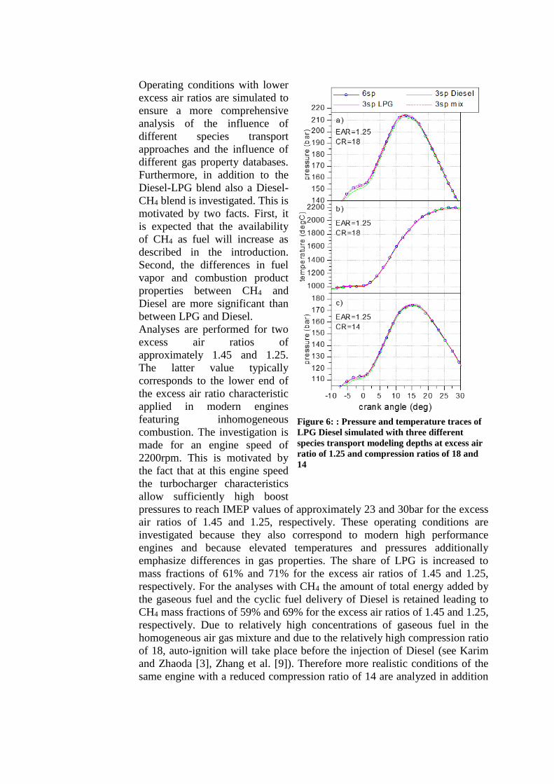
Figure 6: : Pressure and temperature traces of
LPG Diesel simulated with three different
species transport modeling depths at excess air
ratio of 1.25 and compression ratios of 18 and
14
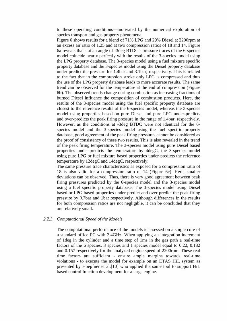
to these operating conditions—motivated by the numerical exploration of
species transport and gas property phenomena.
Figure 6 shows results for a blend of 71% LPG and 29% Diesel at 2200rpm at
an excess air ratio of 1.25 and at two compression ratios of 18 and 14. Figure
6a reveals that - at an angle of -3deg BTDC - pressure traces of the 6-species
model coincide nearly perfectly with the results of the 3-species model using
the LPG property database. The 3-species model using a fuel mixture specific
property database and the 3-species model using the Diesel property database
under-predict the pressure for 1.4bar and 3.1bar, respectively. This is related
to the fact that in the compression stroke only LPG is compressed and thus
the use of the LPG property database leads to more accurate results. The same
trend can be observed for the temperature at the end of compression (Figure
6b). The observed trends change during combustion as increasing fractions of
burned Diesel influence the composition of combustion products. Here, the
results of the 3-species model using the fuel specific property database are
closest to the reference results of the 6-species model, whereas the 3-species
model using properties based on pure Diesel and pure LPG under-predicts
and over-predicts the peak firing pressure in the range of 1.4bar, respectively.
However, as the conditions at -3deg BTDC were not identical for the 6-
species model and the 3-species model using the fuel specific property
database, good agreement of the peak firing pressures cannot be considered as
the proof of consistency of these two results. This is also revealed in the trend
of the peak firing temperature. The 3-species model using pure Diesel based
properties under-predicts the temperature by 4degC, the 3-species model
using pure LPG or fuel mixture based properties under-predicts the reference
temperature by 12degC and 14degC, respectively.
The same pressure trace characteristics as exposed for a compression ratio of
18 is also valid for a compression ratio of 14 (Figure 6c). Here, smaller
deviations can be observed. Thus, there is very good agreement between peak
firing pressures predicted by the 6-species model and the 3-species model
using a fuel specific property database. The 3-species model using Diesel
based or LPG based properties under-predict and over-predict the peak firing
pressure by 0.7bar and 1bar respectively. Although differences in the results
for both compression ratios are not negligible, it can be concluded that they
are relatively small.
2.2.3. Computational Speed of the Models
The computational performance of the models is assessed on a single core of
a standard office PC with 2.4GHz. When applying an integration increment
of 1deg in the cylinder and a time step of 1ms in the gas path a real-time
factors of the 6 species, 3 species and 1 species model equal to 0.22, 0.182
and 0.157 respectively for the analyzed engine speed of 2200rpm. These real
time factors are sufficient - ensure ample margins towards real-time
violations - to execute the model for example on an ETAS HiL system as
presented by Hoepfner et al.[10] who applied the same tool to support HiL
based control function development for a large engine.
CONCLUSION (Should begin 3 lines below the text)
Out of the performed simulations the following conclusions can be drawn:
All species transport modeling depths—from the detailed 6-species to the lumped 3-
species and also 1-species approaches—are real-time capable.
In comparison to the given experimental data the 6-species approach shows very good
agreement proving that the model accurately captures the compression and
combustion characteristics of dual fuel engines operated at various speeds, loads and
gas to Diesel mixing ratios.
The 3-species approach can be seen as a promising simplification to the 6-species
approach especially at higher excess air ratios. The prerequisite for its application is a
thorough preparation of appropriate mixture properties database.
The 1-species approach is recommended only for very crude analysis simulations
since it shows significant deviations to the 3-species and 6-species approaches.
The numerically efficient 6-species approach is also ready to support more complex
combustion models. Surrogate ignition delay models derived from detailed auto-
ignition chemistry simulations (see Walther et al. [11]) fit perfectly to further refine
the explicit rate formulas. Here, the real-time capability of the simulation framework
used in this work is also demonstrated (see Pötsch [12]) for the more complex mixture
controlled combustion models.
REFERENCES
[1] Shah A., Thipse S., Tyagi A., D. Rairikar, Kavthekar K. P., Marathe N. V. and
Mandloi P., “Literature Review and Simulation of Dual Fuel Diesel-CNG
Engines”, SAE Technical Paper 2011-26-0001, 2011
[2] Liu Z. and Karim G. A., “The Ignition Delay Period in Dual Fuel Engines”, SAE
Technical Paper 950466, 1995.
[3] Karim G. and Zhaoda Y., “An Analytical Model for Knock in Dual Fuel Engines
of the Compression Ignition Type”, SAE Technical Paper 880151, 1988
[4] Kordon M., Beer W., Krammer J., Martini E., Schüssler M. and Vitale G.,
“Changing Calibration Paradigms; Innovative ways to increase calibration
quality within the limits of acceptable development effort”, VDI Report Nr.
2169, 441-453, 2012
[5] Wurzenberger J.C., Heinzle R. Deregnaucourt, M. Katrašnik T. “A
Comprehensive Study on Different System Level Engine Simulation Models”,
SAE Technical Paper 2013-01-1116, 2013
[6] Merker G. P. and Schwarz C.: “Combustion Engine Development”, Springer,
Berlin 2010
[7] Wanker R., Wurzenberger J. C., Schuemie H., “Three-Way Catalyst Light-0f
during the NEDC Test Cycle: Fully Coupled 0D/1D Simulation of Gasoline
Combustion, Pollutant Formation and Aftertreatment Systems”, SAE Technical
Paper 2008-01-1755, 2008
[8] Heywood J. B., “Internal Combustion Engine Fundamentals”, McGraw Hill,
1988
[9] Zhang Y., Sagalovich I., De Ojeda W., Ickes A., Wallner T., Wickman D. D.,
“Development of Dual-Fuel Low Temperature Combustion Strategy in a Multi-
Cylinder Heavy-Duty Compression Ignition Engine Using Conventional and
Alternative Fuels” SAE Technical Paper 2013-01-2422, 2013
[10] Hoepfner A., Abart M., Koops I., Przymusinski A., Roduner C., Strasser R. and
Valero-Bertrand D., “New Approach for ECS Software Development”, CIMAC
Congress, Shanghai, 2013
[11] Walther H.-P., Schlatter S., Wachtmeister G. and Boulouchos K.,
“Verbrennungsmodelle für Magerkonzept-Gasmotoren mit Piloteinspritzung”,
MTZ, 73 Nr.2, 2012
[12] Pötsch, C., “Crank-angle resolved modeling of fuel injection and mixing
controlled combustion for real-time application in steady-state and transient
operation”, SAE Technical Paper 14PFL-0252, 2014
[13] Wurzenberger J.C., Katrašnik T., “ Dual Fuel Engine Simulation - A
Thermodynamic Consistent HiL Compatible Model”, SAE Technical Paper
2014-01-1094, 2014
DEFINITIONS/ABBREVIATIONS
Acronyms 0D/3D Zero/Three Dimensional
BMEP Brake Mean Effective Pressure
BTDC Before Top Dead Center
CFD Computational Fluid Dynamics
CNG Compressed Natural Gas
CRA Crank Angle ECU Engine Control Unit
HiL Hardware in the loop
IMEP Indicated Mean Effective Pressure LPG Liquid Petroleum Gas
sp Species
Latin
Letters
AF Air to fuel ratio (kg//kg) B Help variable in energy balance (K.kg/J)
cp Mass specific heat capacity (J/(kg.K)) CR Compression ratio (-)
EAR Excess air ratio (-)
F Flux vector (various) h Mass specific enthalpy of overall gas mixture (J/(kg.K))
Enthalpy flux (W)
IMEP Indicated mean effective pressure (Pa)
K Help variable in energy balance (1/kg) m Mass (kg)
Mass flux (kg/s)
p Pressure (Pa)
R Mass specific gas constant of overall gas mixture (J/(kg.K)) ROHR Rate of heat release (J/deg)
t Time (s)
T Temperature (K) u Mass specific internal energy of overall gas
mixture (J/kg)
V Volume (m3)
w Species mass fraction vector (kg/kg)
x Arbitrary fluid mixture property (various)
Greek
Letters
Excess air ratio (-)
State vector (various)
Indices Air Air
CP Combustion products
DS Downstream FB Fuel burned
FV Fuel vapor
i Index of attached downstream fluxes I Total number of attached downstream fluxes
j Index of attached upstream fluxes J Total number of attached upstream fluxes
l Index of fuel
L Total number of fuels
n Total number of passive species
P Passive
s Species index S Total number of species
stoich Stoichiometric
US Upstream


![Tomaz tadeu da_silva_-_documentos_de_identidade[1]](https://img.pdfslide.tips/doc/110x75/5497b529b479592c778b46ca/tomaz-tadeu-dasilva-documentosdeidentidade1.jpg)