Embed Size (px)
Citation preview
1
Wave Polarization,Polarimetric SAR, and
Polarimetric Scattering Models
Yisok Oh
Dept. of Radio Engineering, Hong-Ik University
다음은 PACRIM Training Course (Workshop)의 강의 Note 중에서
1.1 Wave Properties 만을 발췌한 것으로 ,전파의 성질을 이해하는데 도움이 될 것입니다 .
Seoul National University, February 16-19, 2000
2
Contents
1. Wave Polarization1.1 Wave Properties1.2 Polarization Synthesis
2. Polarimetric Radar System2.1 A Scatterometer System2.2 NASA/JPL POLSAR System
3. Polarimetric Scattering Models3.1 Surface Scattering3.2 Volume Scattering
3
1.1 Wave Properties
-. What is the “Field”?-. Waves : Electromagnetic Waves by Maxwell-. Planewave Propagation in free space-. Polarization : Basic concepts-. Microwave Generation : DC to AC-. Microwave Guidance by Waveguides/ Trans. lines-. Microwave Radiation by Antennas-. EM Wave Reflection from infinite planes-. Microwave Scattering from
-. Point Targets-. Distributed Targets
4
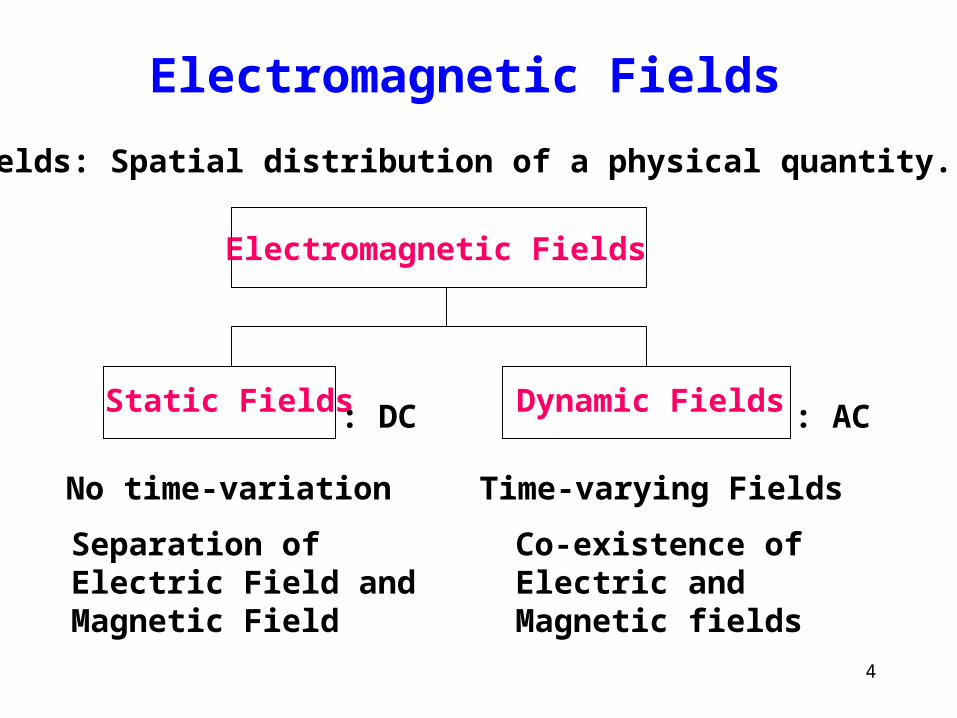
Electromagnetic Fields
Fields: Spatial distribution of a physical quantity.
Static Fields
No time-variation
Separation of Electric Field andMagnetic Field
Electromagnetic Fields
Time-varying Fields
Dynamic Fields
Co-existence ofElectric and Magnetic fields
: DC : AC
5
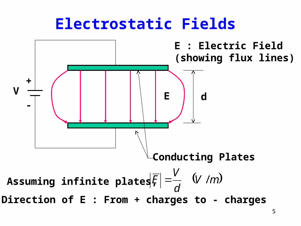
Electrostatic FieldsE : Electric Field(showing flux lines)
Assuming infinite plates, mVd
VE /
V
Conducting Plates
E d
+
-
Direction of E : From + charges to - charges
6
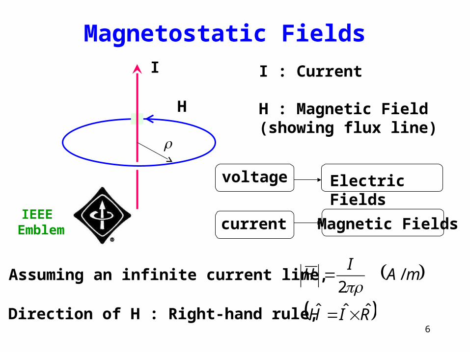
Magnetostatic Fields
IEEE Emblem
I : Current
H : Magnetic Field(showing flux line)
voltage
current
Electric Fields
Magnetic Fields
Assuming an infinite current line, mAI
H /2
I
H
Direction of H : Right-hand rule, RIH ˆˆˆ
7
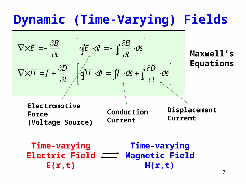
Dynamic (Time-Varying) Fields
c SS
c S
sdt
DsdJldH
t
DJH
sdt
BldE
t
BE
ElectromotiveForce(Voltage Source)
ConductionCurrent
DisplacementCurrent
Maxwell’s Equations
Time-varyingElectric Field
E(r,t)
Time-varyingMagnetic Field
H(r,t)
8
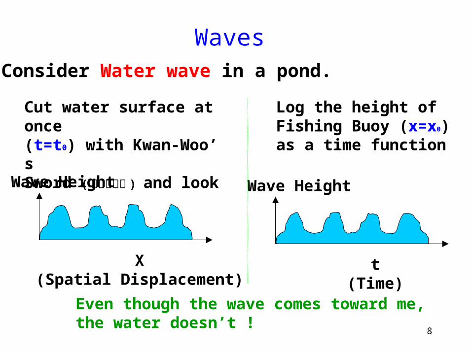
WavesConsider Water wave in a pond.
Cut water surface at once(t=t0) with Kwan-Woo’s Sword ( 청룡언월도 ) and look
X(Spatial Displacement)
Wave Height
Log the height ofFishing Buoy (x=x0)as a time function
t(Time)
Wave Height
Even though the wave comes toward me, the water doesn’t !
9
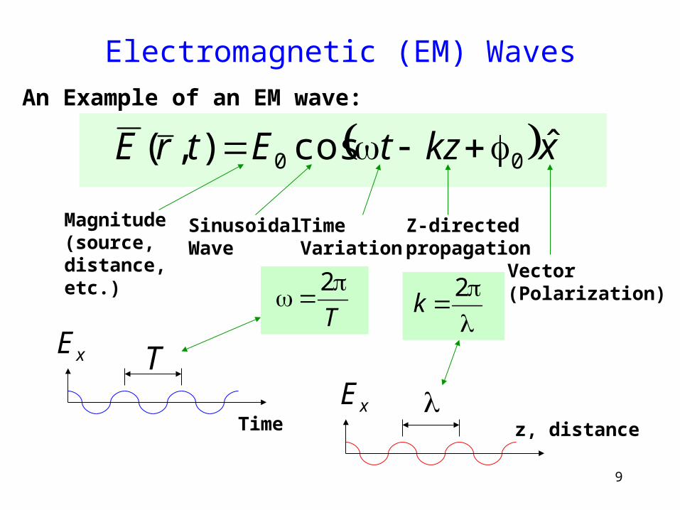
Electromagnetic (EM) Waves
xkztEtrE ˆcos),( 00 An Example of an EM wave:
Magnitude(source,distance,etc.)
SinusoidalWave
TimeVariation
Z-directedpropagation
Vector(Polarization)
T
2
2
k
Time
TxE
z, distancexE
10
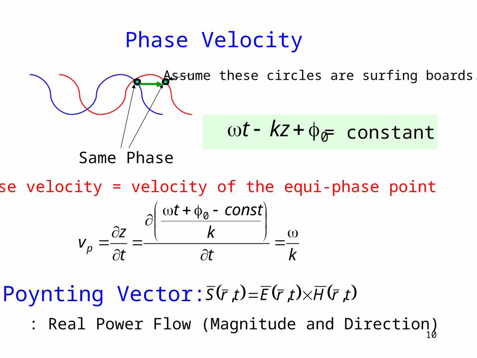
Phase Velocity
0 kzt = constantSame Phase
Assume these circles are surfing boards.
Phase velocity = velocity of the equi-phase point
kt
k
constt
t
zvp
0
Poynting Vector: trHtrEtrS ,,,
: Real Power Flow (Magnitude and Direction)
11
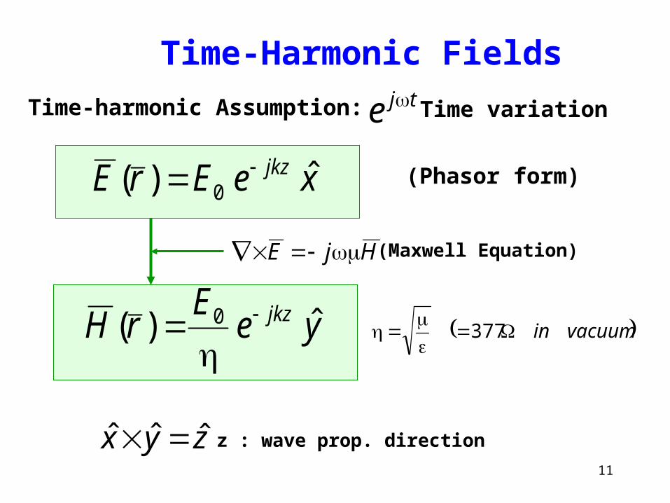
Time-Harmonic Fields
Time-harmonic Assumption: tje Time variation
xeErE jkz ˆ)( 0
yeE
rH jkz ˆ)( 0
HjE (Maxwell Equation)
vacuumin
377
zyx ˆˆˆ z : wave prop. direction
(Phasor form)
12
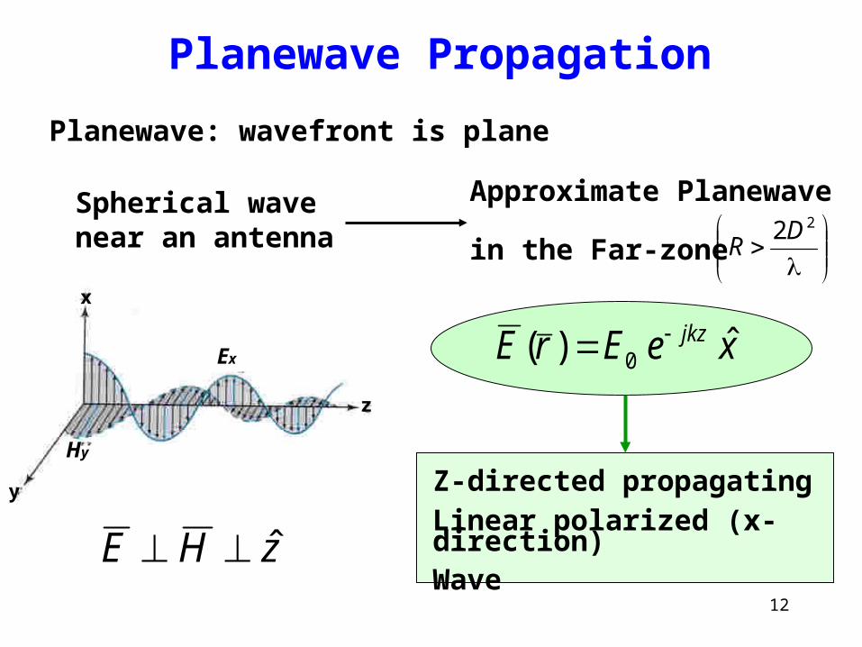
Planewave Propagation
x
y
z
Hy
Ex
zHE ˆ
xeErE jkz ˆ)( 0
Planewave: wavefront is plane
Spherical wave near an antenna
Approximate Planewave
in the Far-zone
22D
R
Z-directed propagatingLinear polarized (x-direction)Wave
13
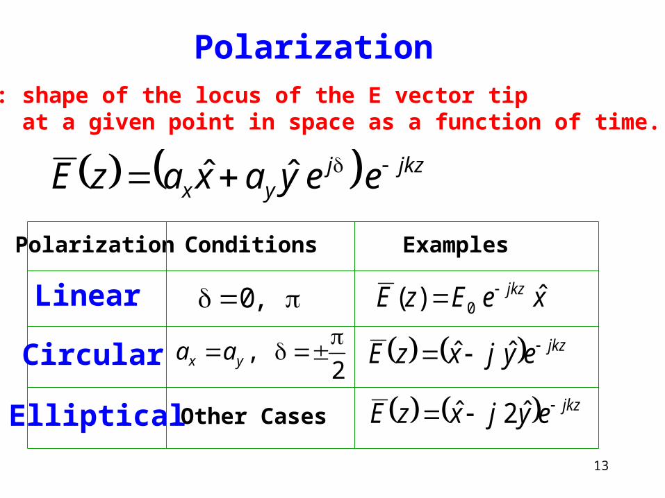
Polarization: shape of the locus of the E vector tip at a given point in space as a function of time.
jkzjyx eeyaxazE ˆˆ
,0
Polarization
Linear
Circular
Elliptical
2,
yx aa
Other Cases
Conditions Examples
xeEzE jkz ˆ)( 0
jkzeyjxzE ˆˆ
jkzeyjxzE ˆ2ˆ
14
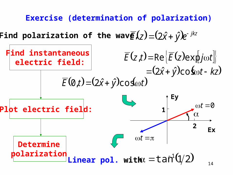
Exercise (determination of polarization)
jkzeyxzE ˆˆ2Find polarization of the wave,
Find instantaneous electric field:
Plot electric field:
Determinepolarization
kztyx
tjzEtzE
cosˆˆ2
expRe,
tyxtE cosˆˆ2,0
2
1
Ex
Ey
0t
t
Linear pol. with 21tan 1
15
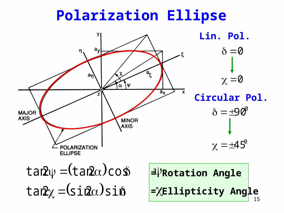
Polarization Ellipse
sin2sin2tan
cos2tan2tan
Lin. Pol.
0
0
Circular Pol.090
045
= Rotation Angle
= Ellipticity Angle
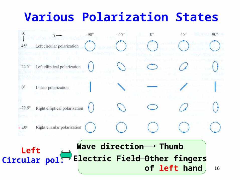
16
Various Polarization States
Left Circular pol.
Wave direction Thumb
Electric Field Other fingers of left hand
17
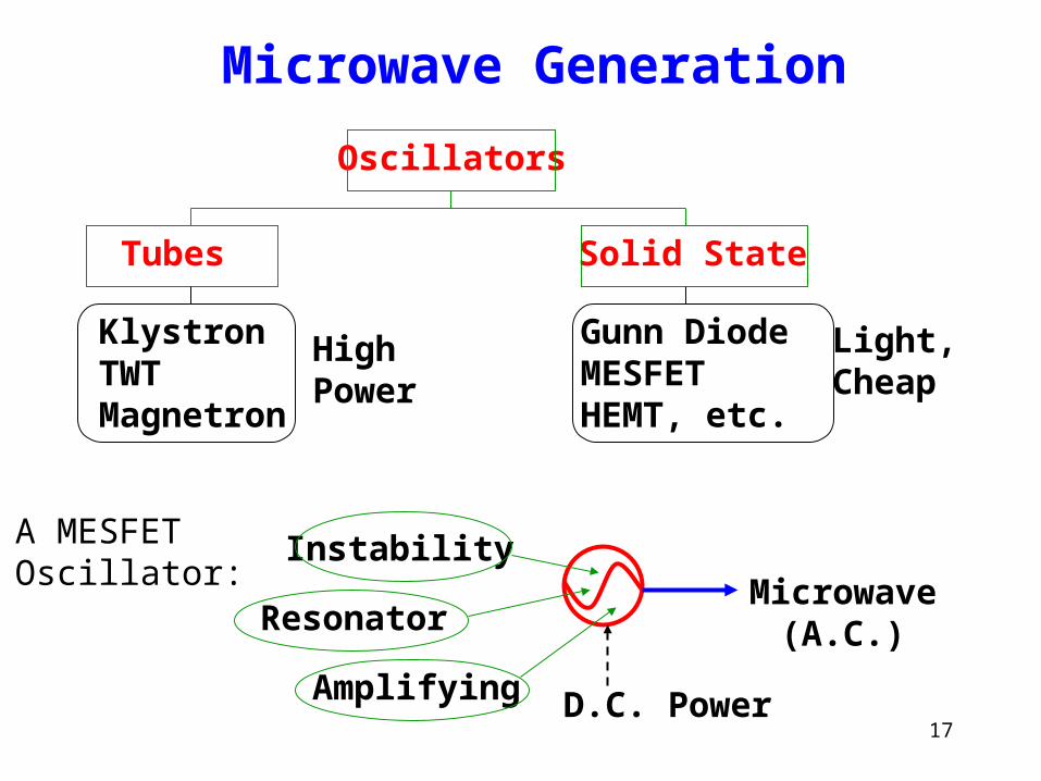
Microwave Generation
Oscillators
Tubes Solid State
KlystronTWTMagnetron
Gunn Diode MESFETHEMT, etc.
High Power
Light, Cheap
D.C. Power
Microwave(A.C.)
Instability
Resonator
Amplifying
A MESFETOscillator:
18
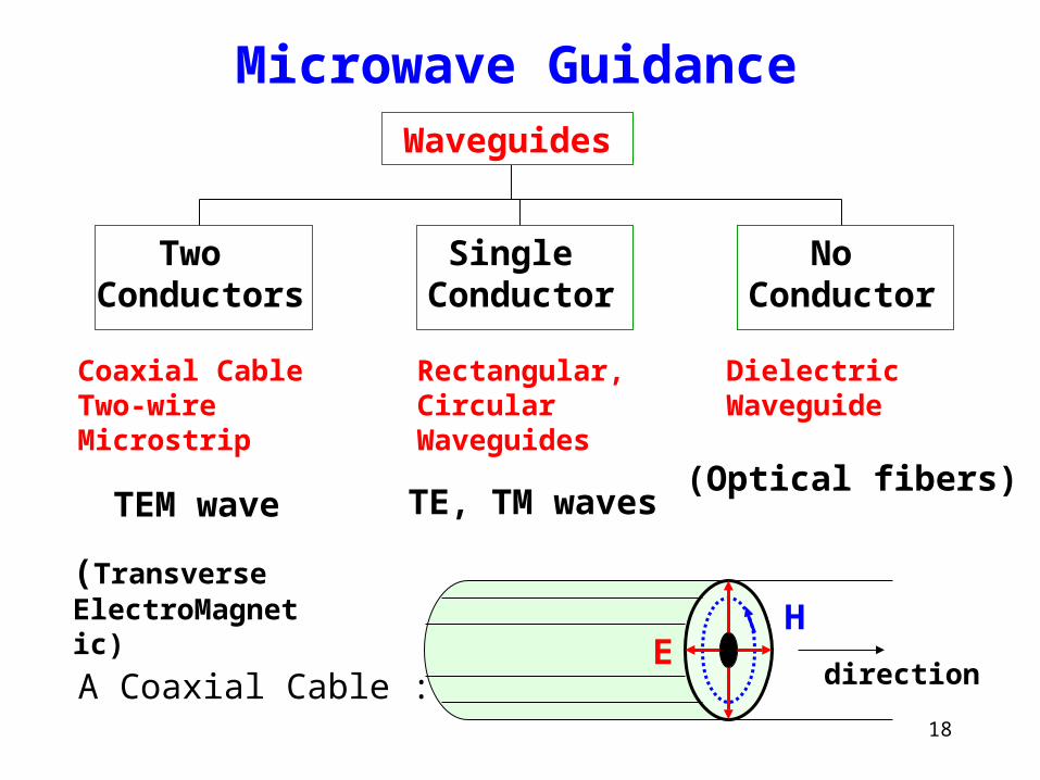
Microwave Guidance
Two Conductors
Single Conductor
No Conductor
(Transverse ElectroMagnetic)
Waveguides
Coaxial CableTwo-wireMicrostrip
Rectangular,CircularWaveguides
DielectricWaveguide
TEM wave TE, TM waves(Optical fibers)
EH
directionA Coaxial Cable :
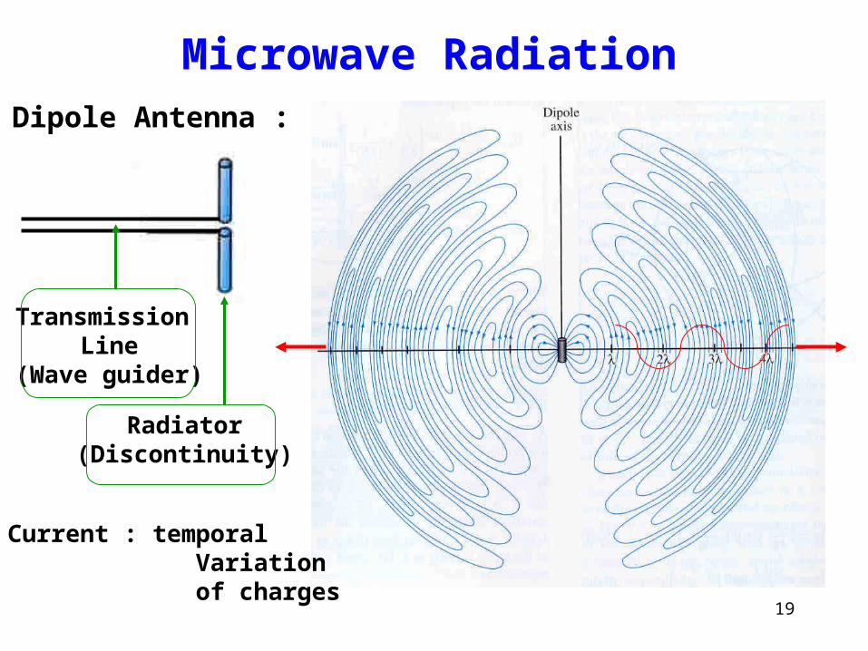
19
Microwave RadiationDipole Antenna :
Transmission Line
(Wave guider)
Radiator(Discontinuity)
* Current : temporal Variation of charges
20
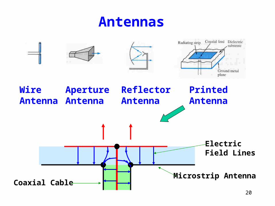
Antennas
WireAntenna
ApertureAntenna
ReflectorAntenna
PrintedAntenna
Microstrip AntennaCoaxial Cable
ElectricField Lines
21
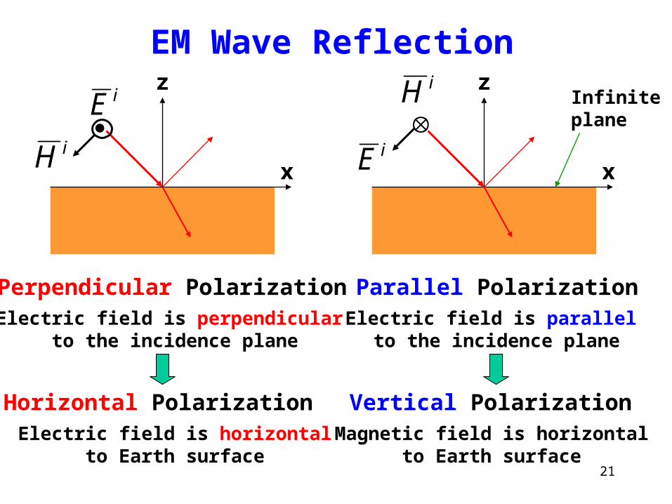
EM Wave ReflectioniE
iH x
z
Perpendicular PolarizationElectric field is perpendicular
to the incidence plane
iE
iH
x
z
Parallel PolarizationElectric field is parallel to the incidence plane
Horizontal PolarizationElectric field is horizontal to Earth surface
Vertical PolarizationMagnetic field is horizontal to Earth surface
Infiniteplane
22
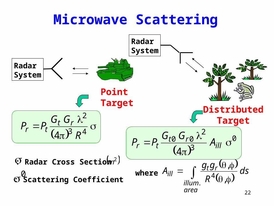
Microwave Scattering
Radar System
Radar System
PointTarget
DistributedTarget
43
2
4 R
GGPP rttr
0
3
200
4
ill
rttr A
GGPP
dsR
ggA
areaillum
rtill
.4 ,
,where
: Radar Cross Section 2m0: Scattering Coefficient


![수능 유형 완전 정복 18.문법의 원리 이해하기d1anutt72n1dwl.cloudfront.net/course/1381124183.0_18.pdf[2014학년도 수능 6월 모평 A․B형 15] 다음은 ‘사전](https://img.pdfslide.tips/doc/110x75/5e5c0e0fc1e0104e49517107/e-oe-e-18ee-e-e-2014ee-e.jpg)


![제1교시 국어영역wdown.ebsi.co.kr/.../20190904/go1/kor_mun_T542ET4C.pdf · 2019-09-04 · 고1 국어영역 1 116 [1~3] 다음은 강연의 일부이다. 물음에 답하시오](https://img.pdfslide.tips/doc/110x75/5ece43a78e3c2e6dd4287537/oe1eoe-ewdownebsicokr20190904go1kormun-2019-09-04.jpg)

![국어영역 - wdown.ebsi.co.krwdown.ebsi.co.kr/W61001/01exam/20171017/go3/kor_mun_tKarvzr0.pdf · 116 [1∼2] 다음은 학생의 발표이다. 물음에 답하시오. 여러분,](https://img.pdfslide.tips/doc/110x75/5e18332d03fedd6a5a53a385/e-wdownebsico-116-1a2-eoe-f-eoeoee-eoe.jpg)
![2019학년도 3월 고3 전국연합학력평가 문제지 국어영역 - EBSiwdown.ebsi.co.kr/W61001/01exam/20190307/go3/kor_mun... · 2019-03-07 · 116 [1~3] 다음은 학생의](https://img.pdfslide.tips/doc/110x75/5f96afa1029d00742f05d13f/2019ee-3-e3-eee-eoe-e-2019-03-07.jpg)


![다음은 우리가 핸드폰 등에 쓰고 있는 리튬 이온 전지는 (i) Li 이 ...gencheminkaist.pe.kr/papers/2004/2004_2_CH103.pdf · 2019-02-11 · [1] 다음은 우리가](https://img.pdfslide.tips/doc/110x75/5cd419c888c993de288bd5c3/-i-li.jpg)


![수험번호:( ) 성명:( ) · 2013-06-01 · 2)다음은㉣과관련된2012개정유치원교육과정(누리과정) 자연탐구영역의일부이다.①과②를채우시오.[2점]](https://img.pdfslide.tips/doc/110x75/5e61bb3dc9b13755eb70743f/e-e-2013-06-01-2eoeeeeeoe2012eoeoeeoeeeee.jpg)