Embed Size (px)
Citation preview
CE 405: Design of Steel Structures – Prof. Dr. A. Varma
1.0 INTRODUCTION TO STRUCTURAL ENGINEERING
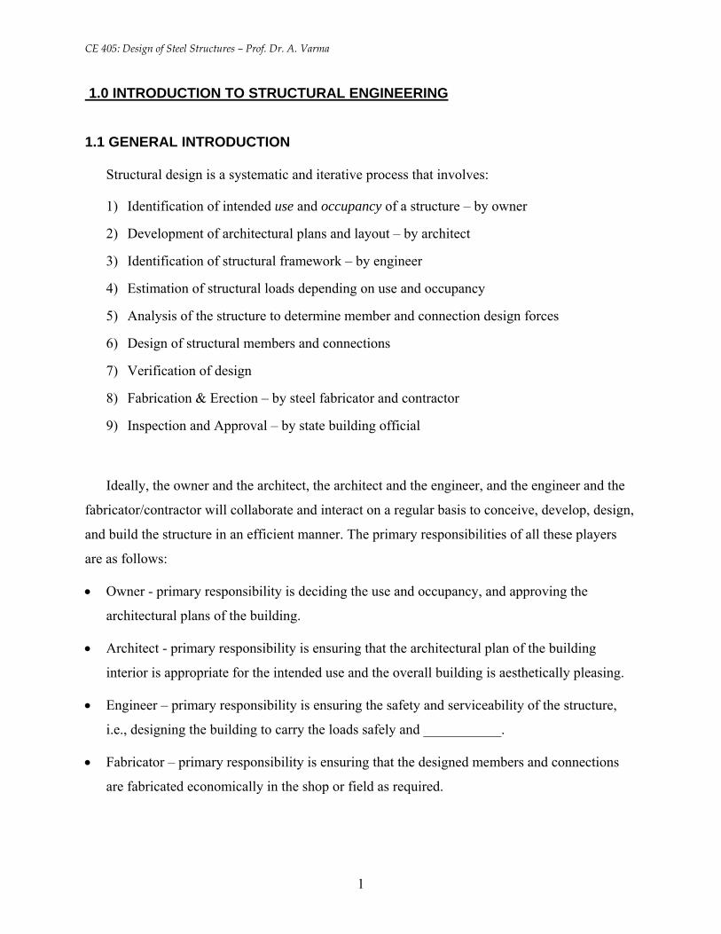
1.1 GENERAL INTRODUCTION
Structural design is a systematic and iterative process that involves:
1) Identification of intended use and occupancy of a structure – by owner
2) Development of architectural plans and layout – by architect
3) Identification of structural framework – by engineer
4) Estimation of structural loads depending on use and occupancy
5) Analysis of the structure to determine member and connection design forces
6) Design of structural members and connections
7) Verification of design
8) Fabrication & Erection – by steel fabricator and contractor
9) Inspection and Approval – by state building official
Ideally, the owner and the architect, the architect and the engineer, and the engineer and the
fabricator/contractor will collaborate and interact on a regular basis to conceive, develop, design,
and build the structure in an efficient manner. The primary responsibilities of all these players
are as follows:
• Owner - primary responsibility is deciding the use and occupancy, and approving the
architectural plans of the building.
• Architect - primary responsibility is ensuring that the architectural plan of the building
interior is appropriate for the intended use and the overall building is aesthetically pleasing.
• Engineer – primary responsibility is ensuring the safety and serviceability of the structure,
i.e., designing the building to carry the loads safely and ___________.
• Fabricator – primary responsibility is ensuring that the designed members and connections
are fabricated economically in the shop or field as required.
1
CE 405: Design of Steel Structures – Prof. Dr. A. Varma
• Contractor/Erector - primary responsibility is ensuring that the members and connections are
economically assembled in the field to build the structure.
• State Building Official – primary responsibility is ensuring that the built structure satisfies
the appropriate building codes accepted by the Govt.
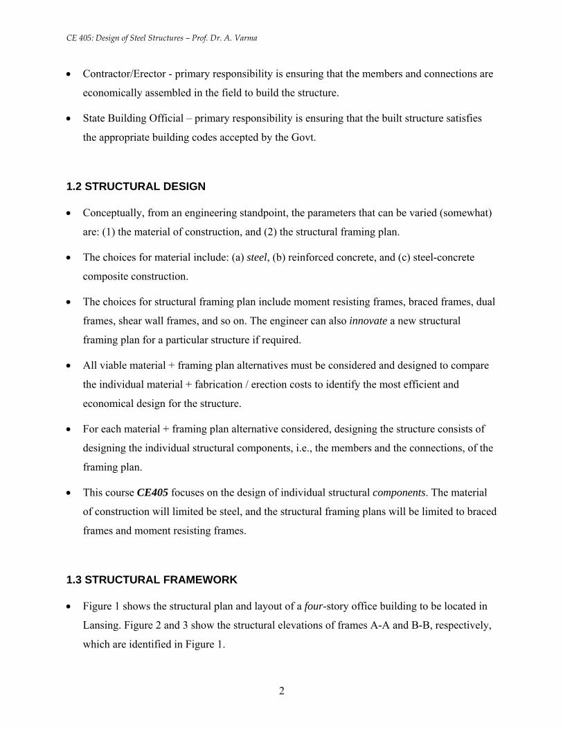
1.2 STRUCTURAL DESIGN
• Conceptually, from an engineering standpoint, the parameters that can be varied (somewhat)
are: (1) the material of construction, and (2) the structural framing plan.
• The choices for material include: (a) steel, (b) reinforced concrete, and (c) steel-concrete
composite construction.
• The choices for structural framing plan include moment resisting frames, braced frames, dual
frames, shear wall frames, and so on. The engineer can also innovate a new structural
framing plan for a particular structure if required.
• All viable material + framing plan alternatives must be considered and designed to compare
the individual material + fabrication / erection costs to identify the most efficient and
economical design for the structure.
• For each material + framing plan alternative considered, designing the structure consists of
designing the individual structural components, i.e., the members and the connections, of the
framing plan.
• This course CE405 focuses on the design of individual structural components. The material
of construction will limited be steel, and the structural framing plans will be limited to braced
frames and moment resisting frames.
1.3 STRUCTURAL FRAMEWORK
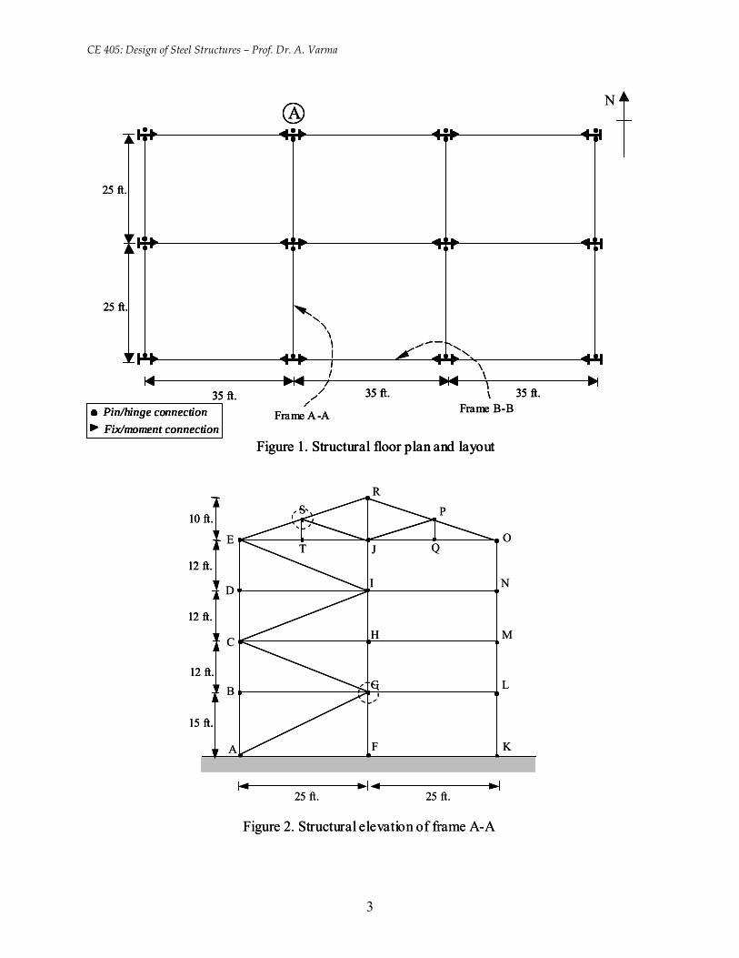
• Figure 1 shows the structural plan and layout of a four-story office building to be located in
Lansing. Figure 2 and 3 show the structural elevations of frames A-A and B-B, respectively,
which are identified in Figure 1.
2
CE 405: Design of Steel Structures – Prof. Dr. A. Varma
35 ft. 35 ft. 35 ft.
25 ft.
25 ft.
A
Figure 1. Structural floor plan and layout
Frame A -A Frame B-B
N
Pin/hinge connectionFix/moment connection
35 ft. 35 ft. 35 ft.
25 ft.
25 ft.
A
Figure 1. Structural floor plan and layout
Frame A -A Frame B-B35 ft. 35 ft. 35 ft.35 ft. 35 ft. 35 ft.
25 ft.
25 ft.
AA
Figure 1. Structural floor plan and layout
Frame A -A Frame B-B
N
Pin/hinge connectionFix/moment connectionPin/hinge connectionFix/moment connectionPin/hinge connectionFix/moment connection
10 ft.
12 ft.
12 ft.
12 ft.
15 ft.
25 ft. 25 ft.
Figure 2. Structural elevation of frame A-A
A
B
C
D
E
F
G
H
I
J
K
L
M
N
O
P
Q
RS
T
10 ft.
12 ft.
12 ft.
12 ft.
15 ft.
10 ft.
12 ft.
12 ft.
12 ft.
15 ft.
25 ft. 25 ft.
Figure 2. Structural elevation of frame A-A
A
B
C
D
E
F
G
H
I
J
K
L
M
N
O
P
Q
RS
T
3
CE 405: Design of Steel Structures – Prof. Dr. A. Varma
10 ft.
12 ft.
12 ft.
12 ft.
15 ft.
35 ft. 35 ft. 35 ft.
a
b
c
d
e
f
g
h
i
j
k
l
m
n
o
p
q
r
s
t
u
v
w
x
y
z
a1
b1
Figure 3. Structural elevation of frame B-B
10 ft.
12 ft.
12 ft.
12 ft.
15 ft.
35 ft. 35 ft. 35 ft.
a
b
c
d
e
f
g
h
i
j
k
l
m
n
o
p
q
r
s
t
u
v
w
x
y
z
a1
b1
10 ft.
12 ft.
12 ft.
12 ft.
15 ft.
35 ft. 35 ft. 35 ft.35 ft. 35 ft. 35 ft.
a
b
c
d
e
f
g
h
i
j
k
l
m
n
o
p
q
r
s
t
u
v
w
x
y
z
a1
b1
Figure 3. Structural elevation of frame B-B
• As shown in Figure 1, the building has two 25-ft. bays in the north-south direction and three
35 ft. bays in the east-west direction.
• There are four structural frames in the north-south direction. These frames have structural
elevations similar to frame A-A shown in Figure 2.
• There are three structural frames in the east-west directions. These frames have structural
elevations similar to frame B-B shown in Figure 3.
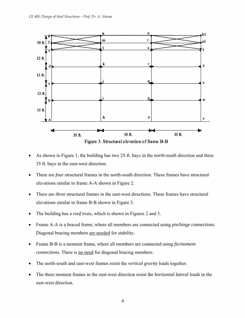
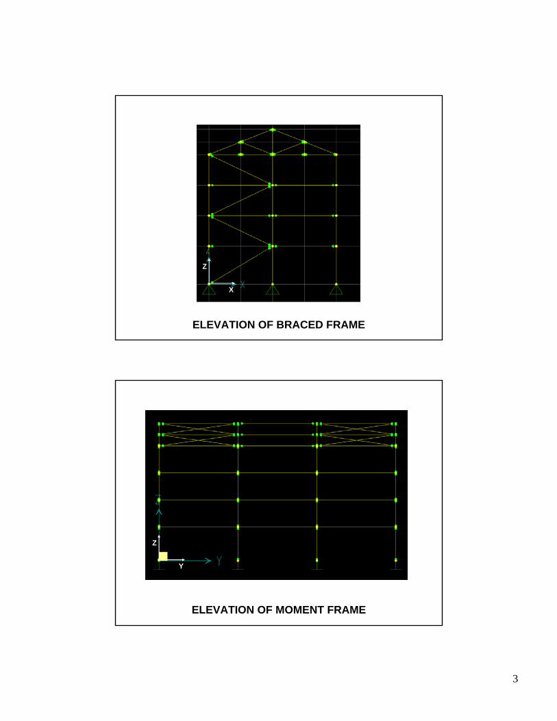
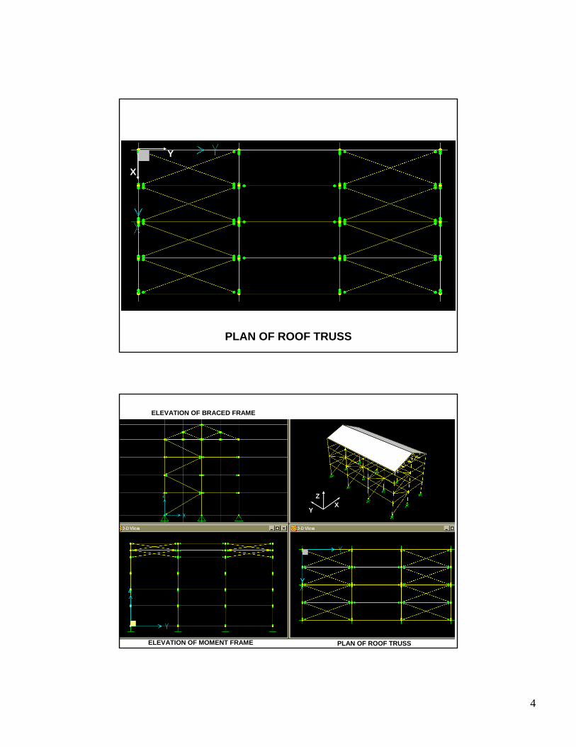
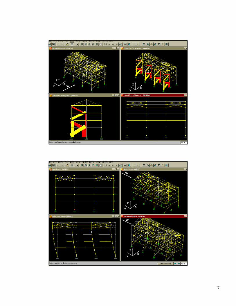
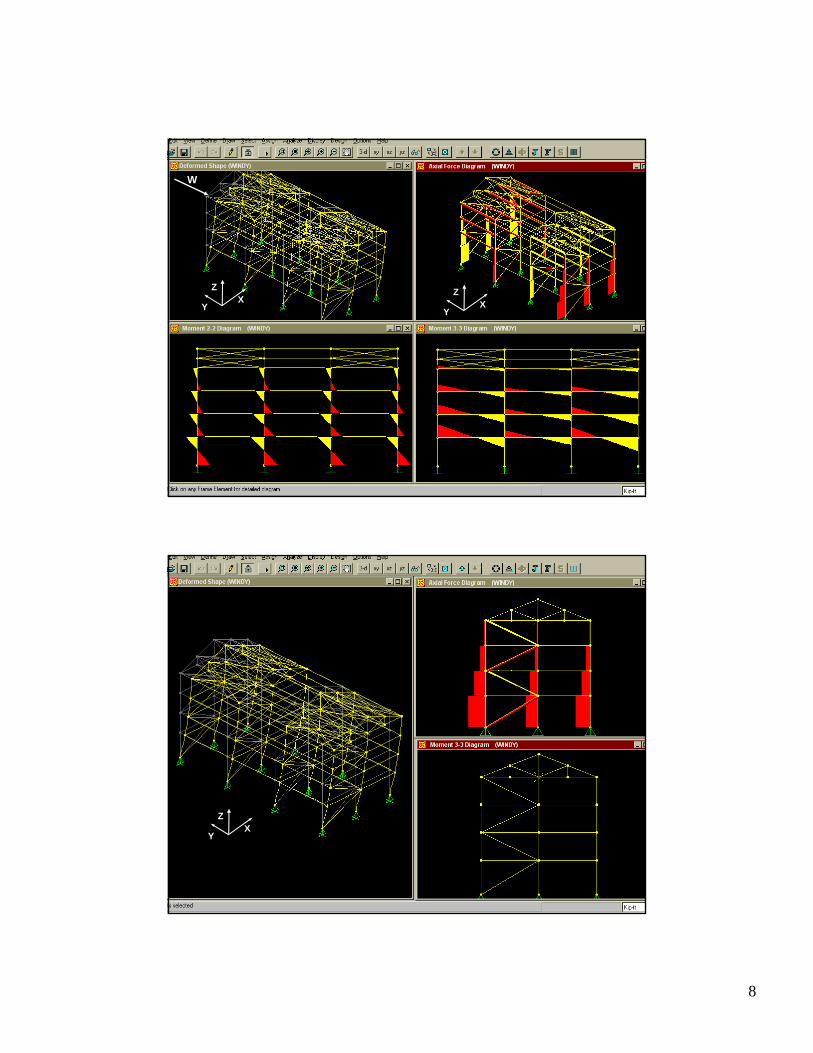
• The building has a roof truss, which is shown in Figures 2 and 3.
• Frame A-A is a braced frame, where all members are connected using pin/hinge connections.
Diagonal bracing members are needed for stability.
• Frame B-B is a moment frame, where all members are connected using fix/moment
connections. There is no need for diagonal bracing members.
• The north-south and east-west frames resist the vertical gravity loads together.
• The three moment frames in the east-west direction resist the horizontal lateral loads in the
east-west direction.
4
1
XY
Z
X
YZ
2
X
YZ
XY
Z
3
X
Z
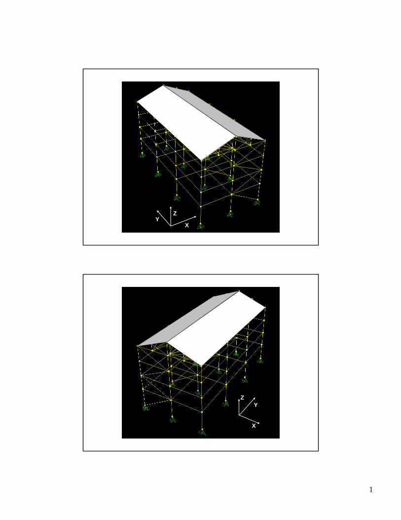
ELEVATION OF BRACED FRAME
Y
Z
ELEVATION OF MOMENT FRAME
4
PLAN OF ROOF TRUSS
Y
X
XY
Z
ELEVATION OF BRACED FRAME
ELEVATION OF MOMENT FRAME PLAN OF ROOF TRUSS
5
XY
Z
XY
ZX
Y
Z
XY
ZX
Y
Z
6
W
7
W XY
ZXY
Z
W
W
XY
Z
XY
Z
8
W
XY
ZX
Y
Z
XY
Z
CE 405: Design of Steel Structures – Prof. Dr. A. Varma
• The four braced frames in the north-south direction resist the horizontal lateral loads in the
north-south direction.
1.4 STRUCTURAL MEMBERS
Structural members are categorized based up on the internal forces in them. For example:
• Tension member –subjected to tensile axial force only
• Column or compression member –subjected to compressive axial force only
• Tension/Compression member –subjected to tensile/compressive axial forces
• Beam member –subjected to flexural loads, i.e., shear force and bending moment only. The
axial force in a beam member is negligible.
• Beam-column member – member subjected to combined axial force and flexural loads (shear
force, and bending moments)
In basic structural analysis (CE305) students have come across two types of structures,
namely, trusses and frames. For example, Figure 2 shows a roof truss supported by a braced
frame.
• All the members of a truss are connected using pin/hinge connections. All external forces are
applied at the pins/hinges. As a result, all truss members are subjected to axial forces (tension
or compression) only.
• In braced and moment frames, the horizontal members (beams) are subjected to flexural
loads only.
• In braced frames, the vertical members (columns) are subjected to compressive axial forces
only.
• In braced frames, the diagonal members (braces) are subjected to tension/compression axial
forces only.
• In moment frames, the vertical members (beam-columns) are subjected to combined axial
and flexural loads.
5
CE 405: Design of Steel Structures – Prof. Dr. A. Varma
For practice, let us categorize the member shown in Figures 2 and 3.
10 ft.
12 ft.
12 ft.
12 ft.
15 ft.
25 ft. 25 ft.
Figure 2. Structural elevation of frame A-A
A
B
C
D
E
F
G
H
I
J
K
L
M
N
O
P
Q
RS
T
10 ft.
12 ft.
12 ft.
12 ft.
15 ft.
10 ft.
12 ft.
12 ft.
12 ft.
15 ft.
25 ft. 25 ft.
Figure 2. Structural elevation of frame A-A
A
B
C
D
E
F
G
H
I
J
K
L
M
N
O
P
Q
RS
T
10 ft.
12 ft.
12 ft.
12 ft.
15 ft.
35 ft. 35 ft. 35 ft.
a
b
c
d
e
f
g
h
i
j
k
l
m
n
o
p
q
r
s
t
u
v
w
x
y
z
a1
b1
Figure 3. Structural elevation of frame B-B
10 ft.
12 ft.
12 ft.
12 ft.
15 ft.
35 ft. 35 ft. 35 ft.
a
b
c
d
e
f
g
h
i
j
k
l
m
n
o
p
q
r
s
t
u
v
w
x
y
z
a1
b1
10 ft.
12 ft.
12 ft.
12 ft.
15 ft.
35 ft. 35 ft. 35 ft.35 ft. 35 ft. 35 ft.
a
b
c
d
e
f
g
h
i
j
k
l
m
n
o
p
q
r
s
t
u
v
w
x
y
z
a1
b1
Figure 3. Structural elevation of frame B-B
6
CE 405: Design of Steel Structures – Prof. Dr. A. Varma
1.5 STRUCTURAL CONNECTIONS
Members of a structural frame are connected together using connections. Prominent
connection types include: (1) truss / bracing member connections; (2) simple shear connections;
(3) fully-restrained moment connections; and (4) partially-restrained flexible moment
connections.
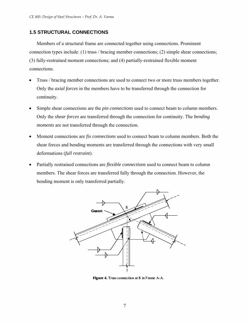
• Truss / bracing member connections are used to connect two or more truss members together.
Only the axial forces in the members have to be transferred through the connection for
continuity.
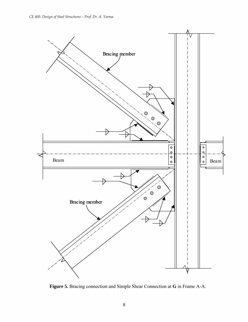
• Simple shear connections are the pin connections used to connect beam to column members.
Only the shear forces are transferred through the connection for continuity. The bending
moments are not transferred through the connection.
• Moment connections are fix connections used to connect beam to column members. Both the
shear forces and bending moments are transferred through the connections with very small
deformations (full restraint).
• Partially restrained connections are flexible connections used to connect beam to column
members. The shear forces are transferred fully through the connection. However, the
bending moment is only transferred partially.
SGusset
Figure 4. Truss connection at S in Frame A-A.
SGusset
SGusset
Figure 4. Truss connection at S in Frame A-A.
7
CE 405: Design of Steel Structures – Prof. Dr. A. Varma
Beam
Bracing member
Bracing member
BeamBeam
Bracing member
Bracing member
Beam
Figure 5. Bracing connection and Simple Shear Connection at G in Frame A-A.
8
CE 405: Design of Steel Structures – Prof. Dr. A. Varma
Beam
Column
Beam
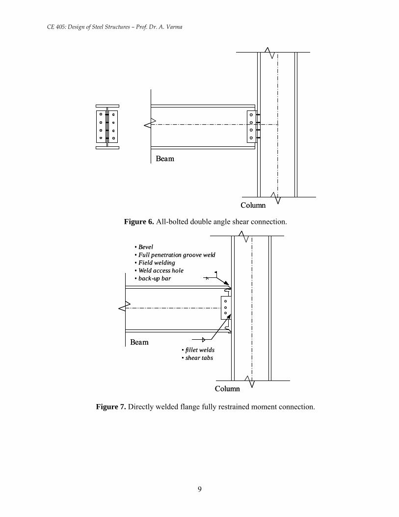
Column Figure 6. All-bolted double angle shear connection.
Beam
Column
• Bevel• Full penetration groove weld• Field welding• Weld access hole• back-up bar
• fillet welds• shear tabs
Beam
Column
• Bevel• Full penetration groove weld• Field welding• Weld access hole• back-up bar
• fillet welds• shear tabs
Figure 7. Directly welded flange fully restrained moment connection.
9
CE 405: Design of Steel Structures – Prof. Dr. A. Varma
• Figure 4 shows an example truss connection. Figure 5 shows an example bracing
connection. Figure 6 shows an example shear connection. Figure 7 shows an example
moment connection.
• Connections are developed using bolts or welds.
• Bolts are used to connect two or more plate elements that are in the same plane. Bolt-
holes are drilled in the plate elements. The threaded bolt shank passes through the holes,
and the connection is secured using nuts.
• Bolts are usually made of higher strength steel.
• Welds can be used to connect plate elements that are in the same or different planes. A
high voltage electric arc is developed between the two plate elements. The electric arc
causes localized melting of the base metal (plate element) and the weld electrode. After
cooling, all the molten metal (base and weld) solidifies into one continuum. Thus,
developing a welded connection.
• In Figure 4, all the truss members are connected together by welding to a common gusset
plate. The axial forces in the members are transferred through the gusset plates. This
same connection can also be developed using bolts. How?
• In Figure 5, the bracing members are connected to gusset plates, which are also
connected to the beam and column. The bracing member can be connected to the gusset
plate using bolts or welds. However, the gusset plate has to be welded to the beam /
column.
• In Figure 6, two angles are bolted to the web of the beam. The perpendicular legs of the
angles are bolted to the flange of the column. Thus, an all-bolted double-angle shear
connection is achieved. This all-bolted connection will be easier to assemble in the field
as compared to welding. How is this a shear connection?
• In Figure 7, the beam flanges are beveled and welded directly to the flange of column
using full penetration groove welds. This welding will have to be done in the field during
erection and it will require the use of back-up bars. Weld-access holes and skilled
welders are required to achieve a weld of acceptable quality.
• In Figure 7, the beam web is bolted to a shear tab (plate), which is fillet welded to the
column in the shop. This shear tab connection transfers the shear from the beam to the
column. How is Figure 7 a moment connection?
10
CE 405: Design of Steel Structures – Prof. Dr. A. Varma
1.6 Structural Loads
The building structure must be designed to carry or resist the loads that are applied to it over
its design-life. The building structure will be subjected to loads that have been categorized as
follows:
• Dead Loads (D): are permanent loads acting on the structure. These include the self-weight
of structural and non-structural components. They are usually gravity loads.
• Live Loads (L): are non-permanent loads acting on the structure due to its use and
occupancy. The magnitude and location of live loads changes frequently over the design life.
Hence, they cannot be estimated with the same accuracy as dead loads.
• Wind Loads (W): are in the form of pressure or suction on the exterior surfaces of the
building. They cause horizontal lateral loads (forces) on the structure, which can be critical
for tall buildings. Wind loads also cause uplift of light roof systems.
• Snow Loads (S): are vertical gravity loads due to snow, which are subjected to variability due
to seasons and drift.
• Roof Live Load (Lr): are live loads on the roof caused during the design life by planters,
people, or by workers, equipment, and materials during maintenance.
• Values of structural loads are given in the publication ASCE 7-98: Minimum Design Loads
for Buildings and Other Structures. The first phase of structural design consists of estimating
the loads acting on the structure. This is done using the load values and combinations
presented in ASCE 7-98 as explained in the following sub-sections.
11
CE 405: Design of Steel Structures – Prof. Dr. A. Varma
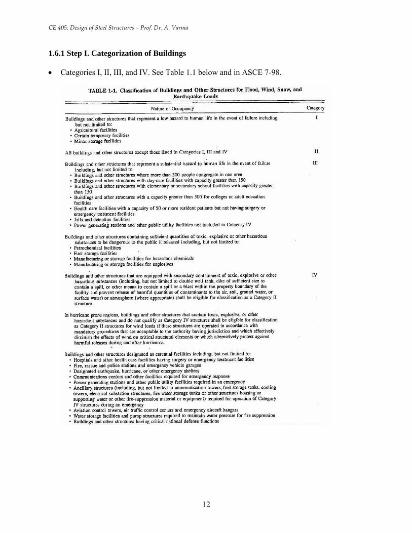
1.6.1 Step I. Categorization of Buildings
• Categories I, II, III, and IV. See Table 1.1 below and in ASCE 7-98.
12
CE 405: Design of Steel Structures – Prof. Dr. A. Varma
1.6.2 Dead Loads (D)
Dead loads consist of the weight of all materials of construction incorporated into the
building including but not limited to walls, floors, roofs, ceilings, stairways, built-in partitions,
finishes, cladding and other similarly incorporated architectural and structural items, and fixed
service equipment such as plumbing stacks and risers, electrical feeders, and heating, ventilating,
and air conditioning systems.
In some cases, the structural dead load can be estimated satisfactorily from simple formulas
based in the weights and sizes of similar structures. For example, the average weight of steel
framed buildings is 60-75 lb/ft2, and the average weight for reinforced concrete buildings is 110 -
130 lb/ft2.
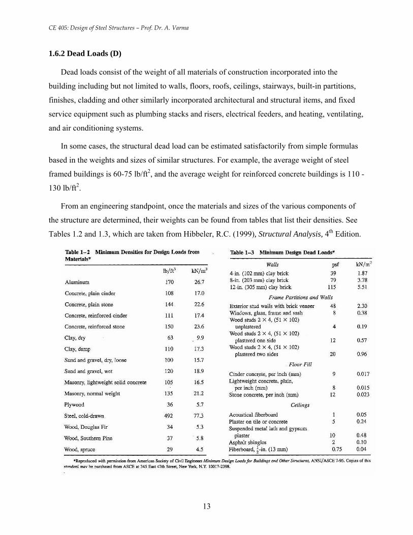
From an engineering standpoint, once the materials and sizes of the various components of
the structure are determined, their weights can be found from tables that list their densities. See
Tables 1.2 and 1.3, which are taken from Hibbeler, R.C. (1999), Structural Analysis, 4th Edition.
13
CE 405: Design of Steel Structures – Prof. Dr. A. Varma
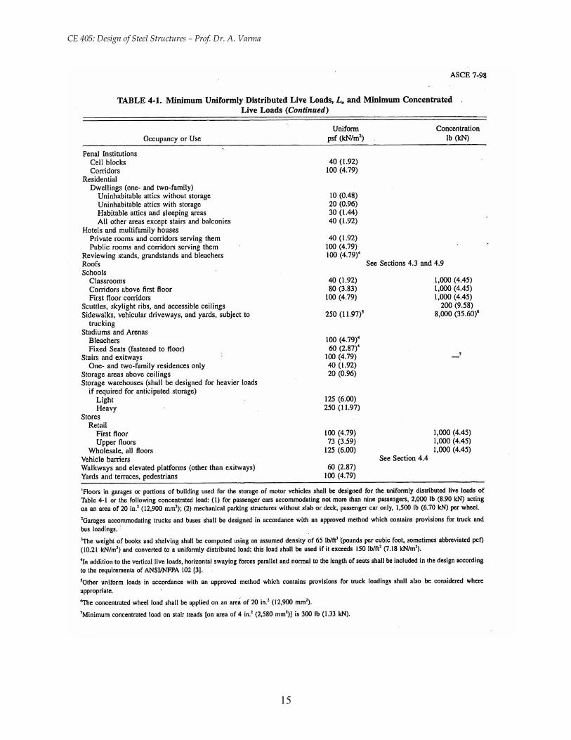
1.6.3 Live Loads
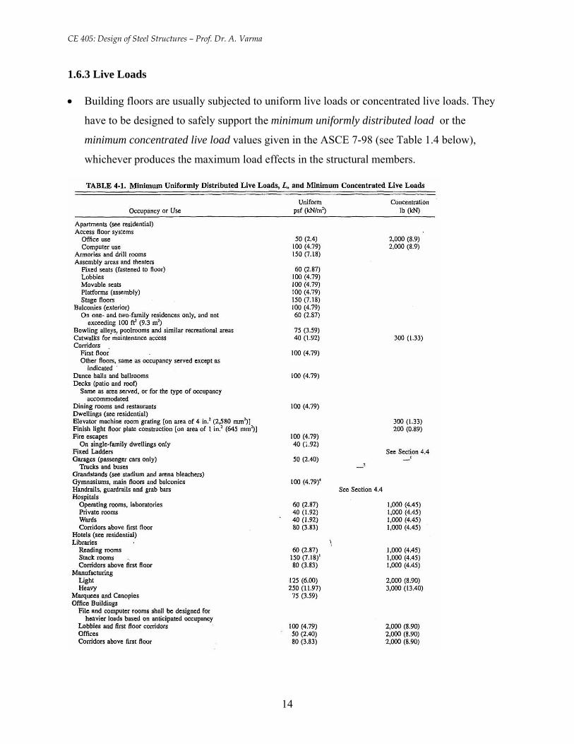
• Building floors are usually subjected to uniform live loads or concentrated live loads. They
have to be designed to safely support the minimum uniformly distributed load or the
minimum concentrated live load values given in the ASCE 7-98 (see Table 1.4 below),
whichever produces the maximum load effects in the structural members.
14
CE 405: Design of Steel Structures – Prof. Dr. A. Varma
15
CE 405: Design of Steel Structures – Prof. Dr. A. Varma
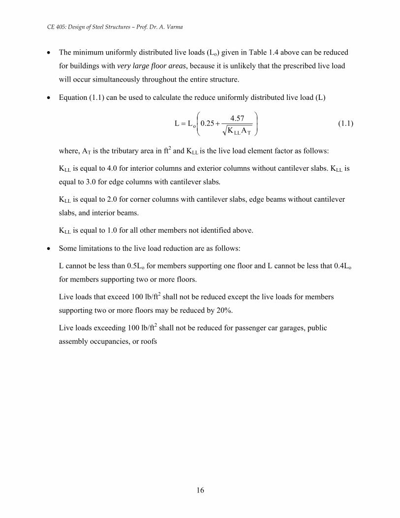
• The minimum uniformly distributed live loads (Lo) given in Table 1.4 above can be reduced
for buildings with very large floor areas, because it is unlikely that the prescribed live load
will occur simultaneously throughout the entire structure.
• Equation (1.1) can be used to calculate the reduce uniformly distributed live load (L)
⎟⎟⎠
⎞⎜⎜⎝
⎛+=
TLLo AK
57.425.0LL (1.1)
where, AT is the tributary area in ft2 and KLL is the live load element factor as follows:
KLL is equal to 4.0 for interior columns and exterior columns without cantilever slabs. KLL is
equal to 3.0 for edge columns with cantilever slabs.
KLL is equal to 2.0 for corner columns with cantilever slabs, edge beams without cantilever
slabs, and interior beams.
KLL is equal to 1.0 for all other members not identified above.
• Some limitations to the live load reduction are as follows:
L cannot be less than 0.5Lo for members supporting one floor and L cannot be less that 0.4Lo
for members supporting two or more floors.
Live loads that exceed 100 lb/ft2 shall not be reduced except the live loads for members
supporting two or more floors may be reduced by 20%.
Live loads exceeding 100 lb/ft2 shall not be reduced for passenger car garages, public
assembly occupancies, or roofs
16
CE 405: Design of Steel Structures – Prof. Dr. A. Varma
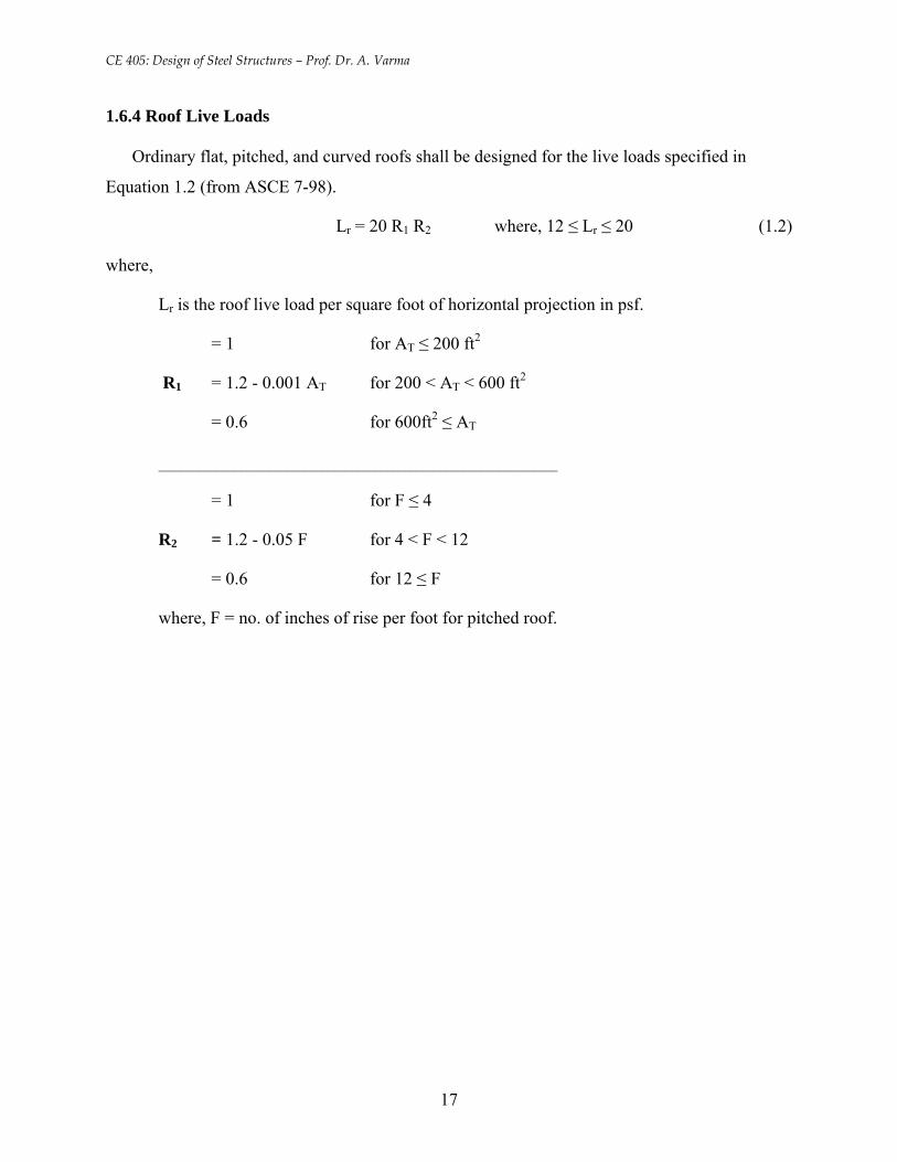
1.6.4 Roof Live Loads
Ordinary flat, pitched, and curved roofs shall be designed for the live loads specified in
Equation 1.2 (from ASCE 7-98).
Lr = 20 R1 R2 where, 12 ≤ Lr ≤ 20 (1.2)
where,
Lr is the roof live load per square foot of horizontal projection in psf.
= 1 for AT ≤ 200 ft2
R1 = 1.2 - 0.001 AT for 200 < AT < 600 ft2
= 0.6 for 600ft2 ≤ AT
____________________________________________________________________
= 1 for F ≤ 4
R2 = 1.2 - 0.05 F for 4 < F < 12
= 0.6 for 12 ≤ F
where, F = no. of inches of rise per foot for pitched roof.
17
CE 405: Design of Steel Structures – Prof. Dr. A. Varma
1.6.5 Wind Loads
• Design wind loads for buildings can be based on: (a) simplified procedure; (b) analytical
procedure; and (c) wind tunnel or small-scale procedure.
• Refer to ASCE 7-98 for the simplified procedure. This simplified procedure is applicable
only to buildings with mean roof height less than 30 ft.
• The wind tunnel procedure consists of developing a small-scale model of the building and
testing it in a wind tunnel to determine the expected wind pressures etc. It is expensive and
may be utilized for difficult or special situations.
• The analytical procedure is used in most design offices. It is fairly systematic but somewhat
complicated to account for the various situations that can occur:
• Wind velocity will cause pressure on any surface in its path. The wind velocity and hence the
velocity pressure depend on the height from the ground level. Equation 1.3 is recommended
by ASCE 7-98 for calculating the velocity pressure (qz) in lb/ft2
qz = 0.00256 Kz Kzt Kd V2 I (lb/ft2) (1.3)
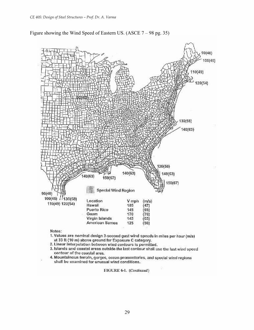
where, V is the wind velocity (see Figure 6-1 in ASCE 7-98)
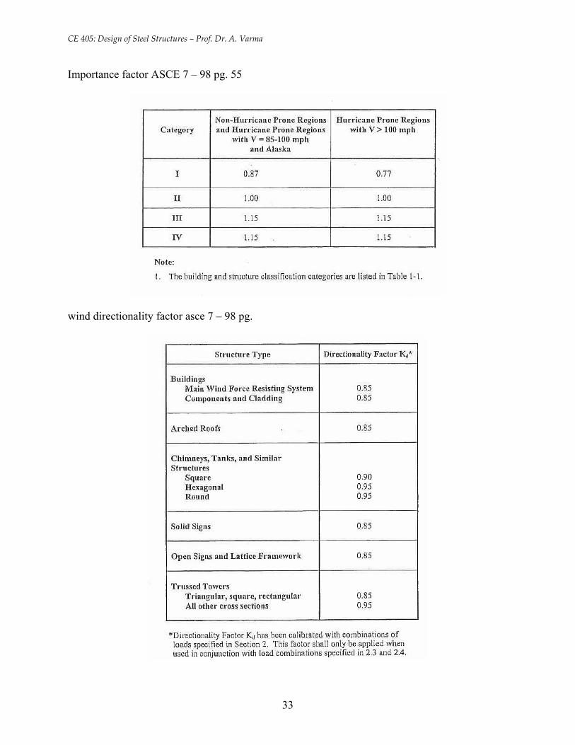
Kd is a directionality factor (=0.85 for CE 405)
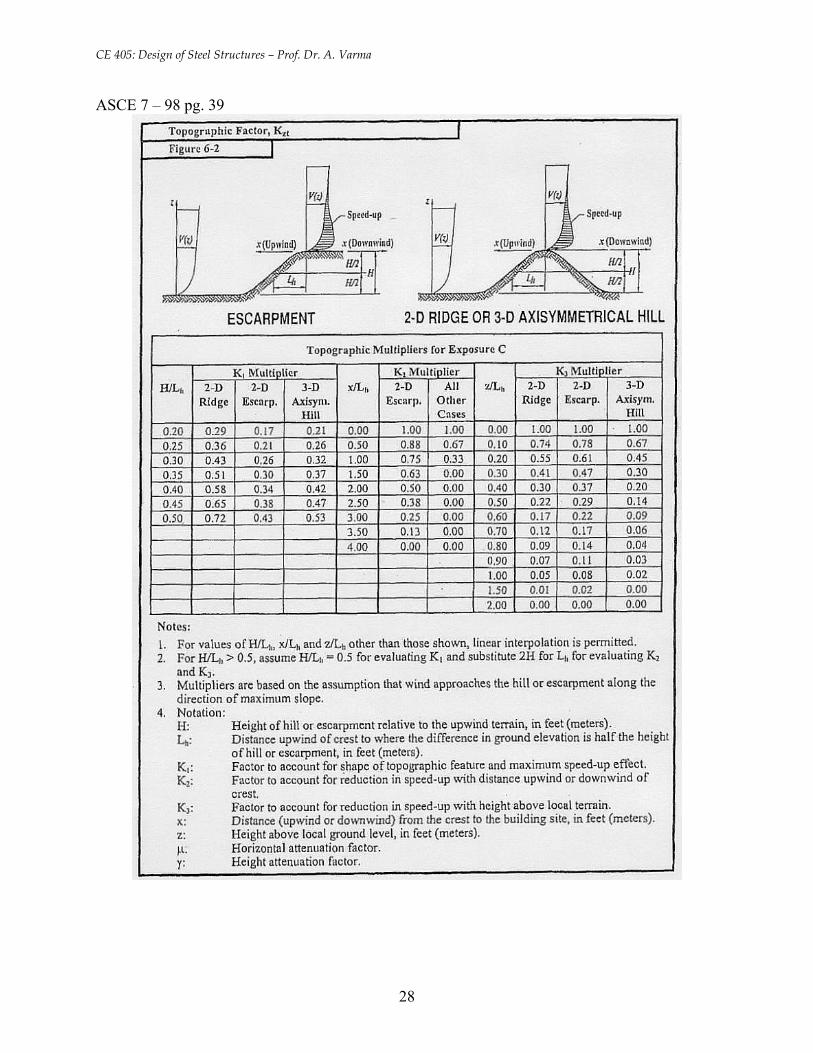
Kzt is a topographic factor (= 1.0 for CE 405)
I is the importance factor (=1.0 for CE 405)
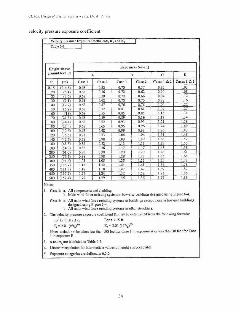
Kz varies with height z above the ground level (see Table 6-5 in ASCE 7-98)
• A significant portion of the U.S. including Lansing has V = 90 mph. At these location
qz = 17.625 Kz (lb/ft2) (1.4)
18
CE 405: Design of Steel Structures – Prof. Dr. A. Varma
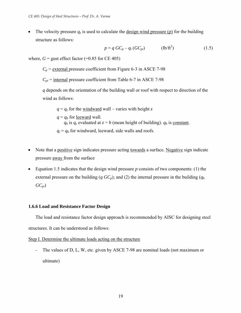
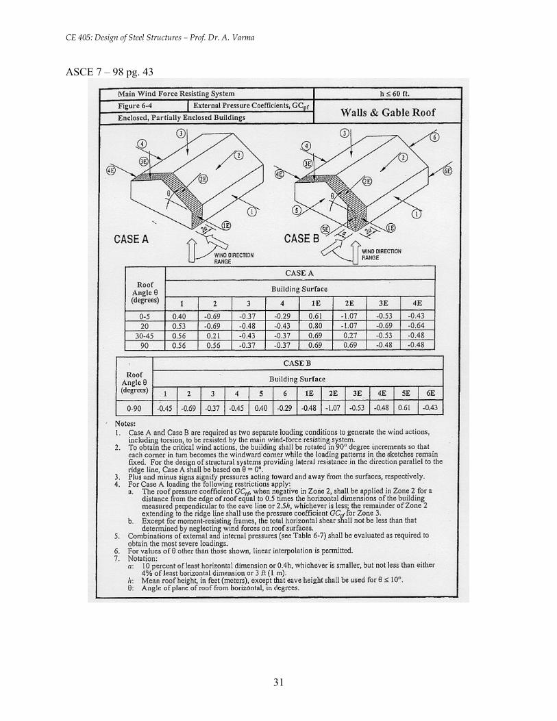
• The velocity pressure qz is used to calculate the design wind pressure (p) for the building
structure as follows:
p = q GCp – qi (GCpi) (lb/ft2) (1.5)
where, G = gust effect factor (=0.85 for CE 405)
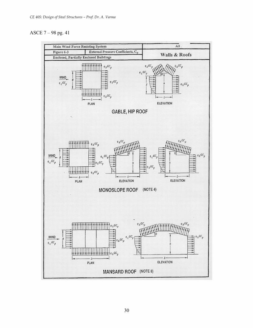
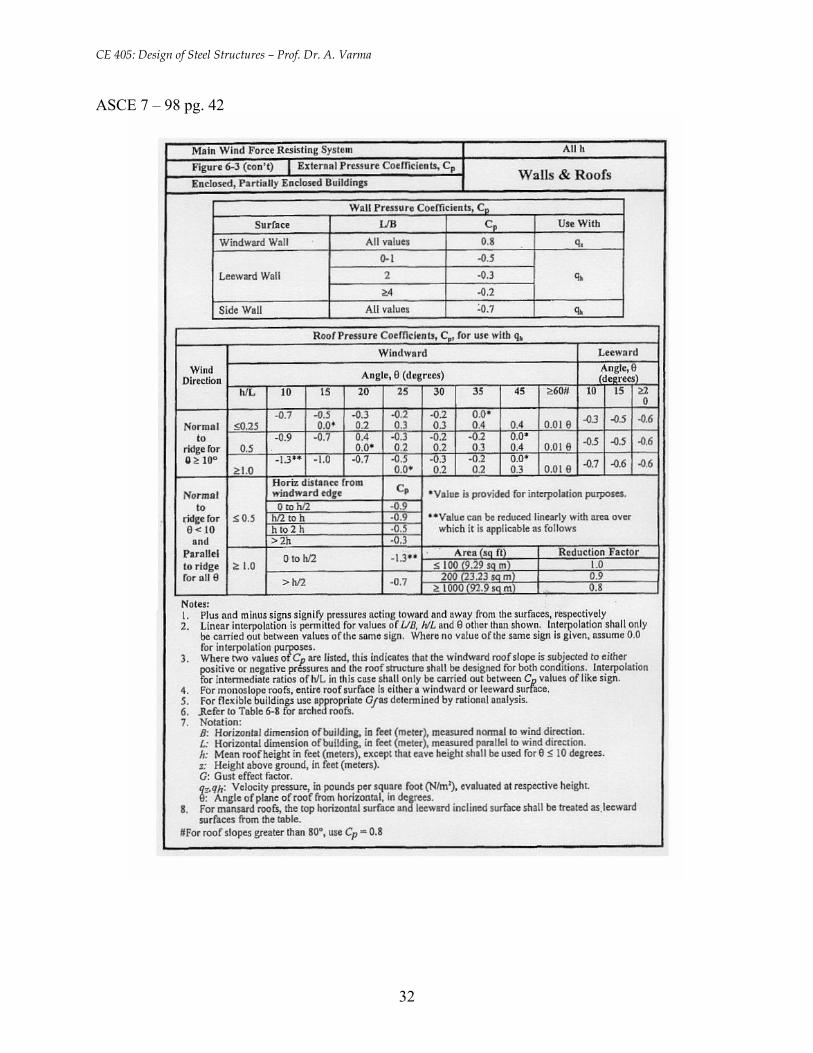
Cp = external pressure coefficient from Figure 6-3 in ASCE 7-98
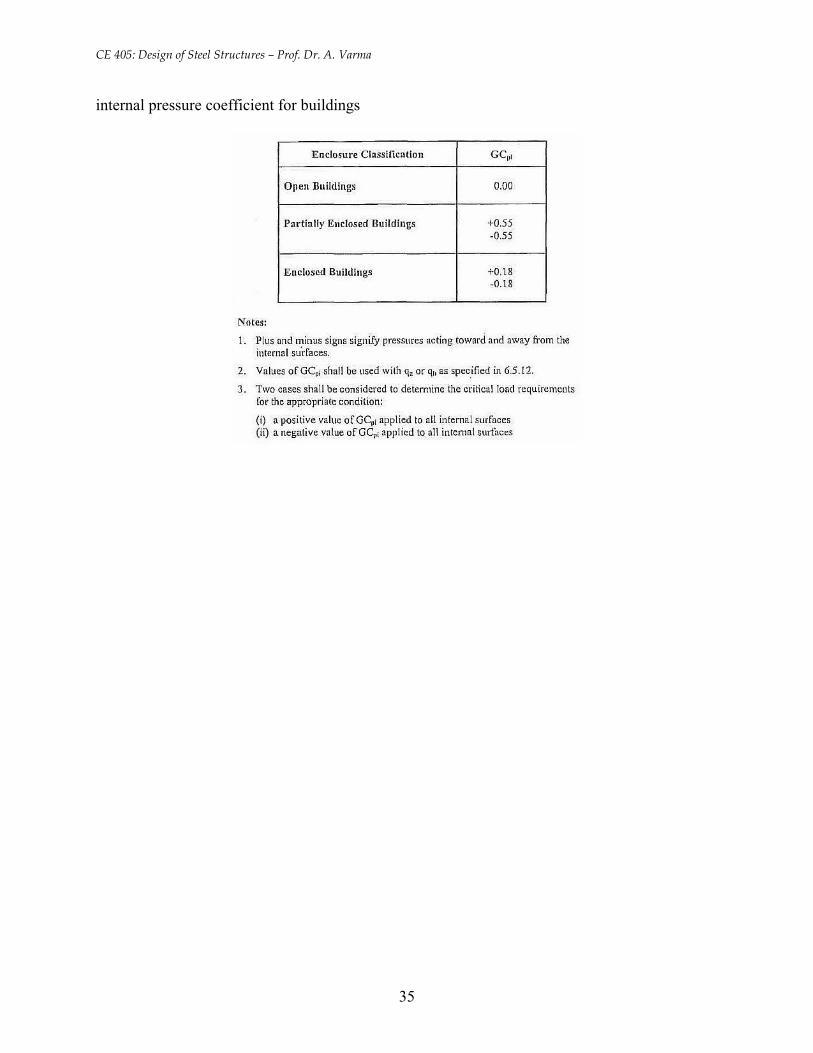
Cpi = internal pressure coefficient from Table 6-7 in ASCE 7-98
q depends on the orientation of the building wall or roof with respect to direction of the
wind as follows:
q = qz for the windward wall – varies with height z
q = qh for leeward wall. qh is qz evaluated at z = h (mean height of building). qh is constant.
qi = qh for windward, leeward, side walls and roofs.
• Note that a positive sign indicates pressure acting towards a surface. Negative sign indicate
pressure away from the surface
• Equation 1.5 indicates that the design wind pressure p consists of two components: (1) the
external pressure on the building (q GCp); and (2) the internal pressure in the building (qh
GCpi)
1.6.6 Load and Resistance Factor Design
The load and resistance factor design approach is recommended by AISC for designing steel
structures. It can be understood as follows:
Step I. Determine the ultimate loads acting on the structure
- The values of D, L, W, etc. given by ASCE 7-98 are nominal loads (not maximum or
ultimate)
19
CE 405: Design of Steel Structures – Prof. Dr. A. Varma
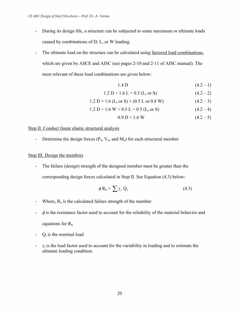
- During its design life, a structure can be subjected to some maximum or ultimate loads
caused by combinations of D, L, or W loading.
- The ultimate load on the structure can be calculated using factored load combinations,
which are given by ASCE and AISC (see pages 2-10 and 2-11 of AISC manual). The
most relevant of these load combinations are given below:
1.4 D (4.2 – 1)
1.2 D + 1.6 L + 0.5 (Lr or S) (4.2 – 2)
1.2 D + 1.6 (Lr or S) + (0.5 L or 0.8 W) (4.2 – 3)
1.2 D + 1.6 W + 0.5 L + 0.5 (Lr or S) (4.2 – 4)
0.9 D + 1.6 W (4.2 – 5)
Step II. Conduct linear elastic structural analysis
- Determine the design forces (Pu, Vu, and Mu) for each structural member
Step III. Design the members
- The failure (design) strength of the designed member must be greater than the
corresponding design forces calculated in Step II. See Equation (4.3) below:
φ Rn > ∑γ ii Q (4.3)
- Where, Rn is the calculated failure strength of the member
- φ is the resistance factor used to account for the reliability of the material behavior and
equations for Rn
- Qi is the nominal load
- γi is the load factor used to account for the variability in loading and to estimate the ultimate loading condition.
20
CE 405: Design of Steel Structures – Prof. Dr. A. Varma
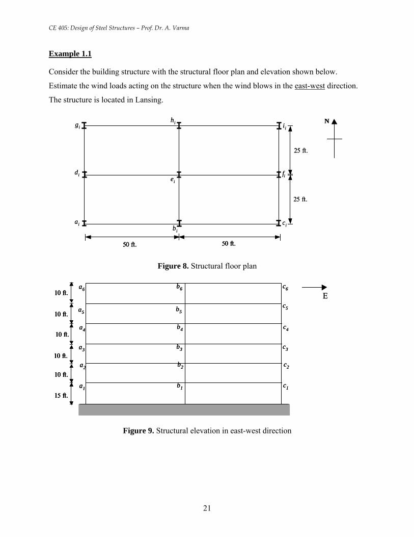
Example 1.1
Consider the building structure with the structural floor plan and elevation shown below.
Estimate the wind loads acting on the structure when the wind blows in the east-west direction.
The structure is located in Lansing.
25 ft.
50 ft.50 ft.
25 ft.
N
aibi
ci
diei
fi
gihi ii
25 ft.
50 ft.50 ft. 50 ft.50 ft.
25 ft.
N
aibi
ci
diei
fi
gihi ii
Figure 8. Structural floor plan
E10 ft.
10 ft.
10 ft.
10 ft.
10 ft.
15 ft.a1 b1 c1
a2 b2 c2
a3 b3 c3
a4 b4 c4
a5 b5c5
a6 b6 c6
E10 ft.
10 ft.
10 ft.
10 ft.
10 ft.
15 ft.a1 b1 c1
a2 b2 c2
a3 b3 c3
a4 b4 c4
a5 b5c5
a6 b6 c610 ft.
10 ft.
10 ft.
10 ft.
10 ft.
15 ft.
10 ft.
10 ft.
10 ft.
10 ft.
10 ft.
15 ft.a1 b1 c1
a2 b2 c2
a3 b3 c3
a4 b4 c4
a5 b5c5
a6 b6 c6
Figure 9. Structural elevation in east-west direction
21
CE 405: Design of Steel Structures – Prof. Dr. A. Varma
b 6
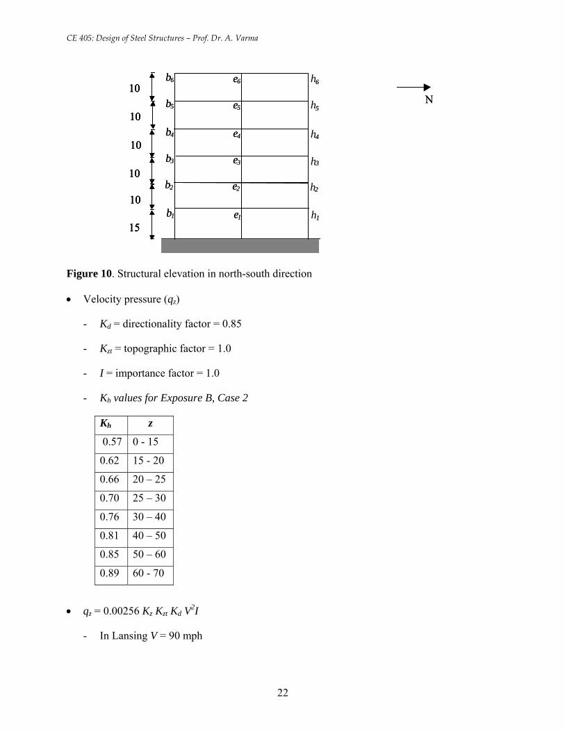
Figure 10. Structural elevation in north-south direction
• Velocity pressure (qz)
- Kd = directionality factor = 0.85
- Kzt = topographic factor = 1.0
- I = importance factor = 1.0
- Kh values for Exposure B, Case 2
Kh z
0.57 0 - 15
0.62 15 - 20
0.66 20 – 25
0.70 25 – 30
0.76 30 – 40
0.81 40 – 50
0.85 50 – 60
0.89 60 - 70
• qz = 0.00256 Kz Kzt Kd V2I
- In Lansing V = 90 mph
N N 10
10
10
10
10
15 b 1 e1 1
b 2 e2 2
b 3 e3 3
b 4 e4 4
b 5 e5 5
e6 6b 6 e 6h610 10 10
b 5 e 5h510 10 10
b 4 e 4h410 10 10
b 3 e 3h3
10 10 10 b 2 e 2h2
10 10 10 b 1 e
15 15 15 1 1h
22
CE 405: Design of Steel Structures – Prof. Dr. A. Varma
- qz = 17.625 Kz psf
• Wind pressure (p)
- Gust factor = G = 0.85
- For wind in east west direction; L/B = Length / width = 2.0
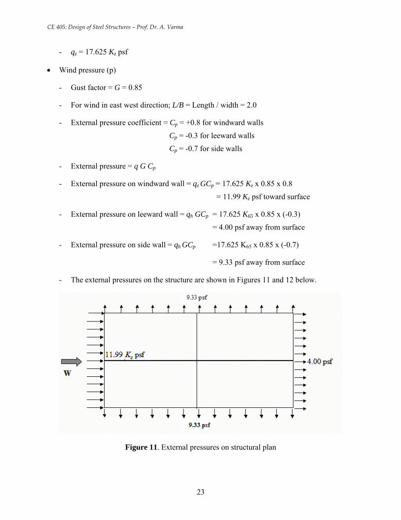
- External pressure coefficient = Cp = +0.8 for windward walls
Cp = -0.3 for leeward walls
Cp = -0.7 for side walls
- External pressure = q G Cp
- External pressure on windward wall = qz GCp = 17.625 Kz x 0.85 x 0.8
= 11.99 Kz psf toward surface
- External pressure on leeward wall = qh GCp = 17.625 K65 x 0.85 x (-0.3)
= 4.00 psf away from surface
- External pressure on side wall = qh GCp =17.625 K65 x 0.85 x (-0.7)
= 9.33 psf away from surface
- The external pressures on the structure are shown in Figures 11 and 12 below.
Figure 11. External pressures on structural plan
23
CE 405: Design of Steel Structures – Prof. Dr. A. Varma
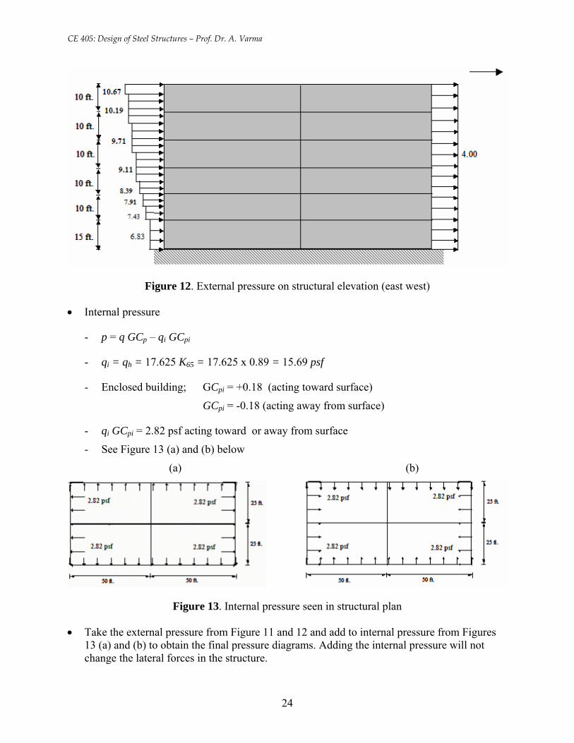
Figure 12. External pressure on structural elevation (east west)
• Internal pressure
- p = q GCp – qi GCpi
- qi = qh = 17.625 K65 = 17.625 x 0.89 = 15.69 psf
- Enclosed building; GCpi = +0.18 (acting toward surface)
GCpi = -0.18 (acting away from surface)
- qi GCpi = 2.82 psf acting toward or away from surface
- See Figure 13 (a) and (b) below
(a) (b)
Figure 13. Internal pressure seen in structural plan
• Take the external pressure from Figure 11 and 12 and add to internal pressure from Figures 13 (a) and (b) to obtain the final pressure diagrams. Adding the internal pressure will not change the lateral forces in the structure.
24
CE 405: Design of Steel Structures – Prof. Dr. A. Varma
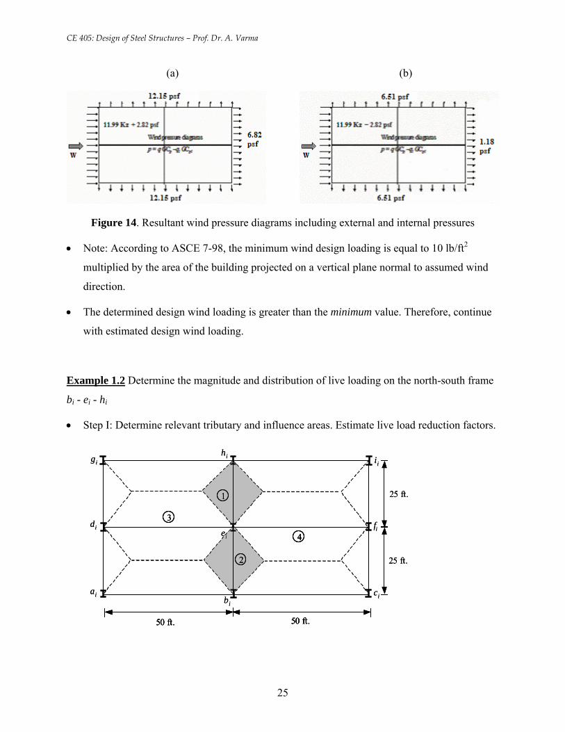
(a) (b)
Figure 14. Resultant wind pressure diagrams including external and internal pressures
• Note: According to ASCE 7-98, the minimum wind design loading is equal to 10 lb/ft2
multiplied by the area of the building projected on a vertical plane normal to assumed wind
direction.
• The determined design wind loading is greater than the minimum value. Therefore, continue
with estimated design wind loading.
Example 1.2 Determine the magnitude and distribution of live loading on the north-south frame
bi - ei - hi
• Step I: Determine relevant tributary and influence areas. Estimate live load reduction factors.
25 ft.
50 ft.50 ft.
25 ft.
aibi
ci
diei
fi
gihi ii
1
2
3
4
25 ft.
50 ft.50 ft. 50 ft.50 ft.
25 ft.
aibi
ci
diei
fi
gihi ii
11
22
33
44
25
CE 405: Design of Steel Structures – Prof. Dr. A. Varma
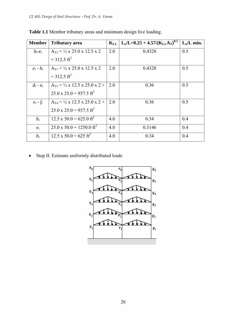
Table 1.1 Member tributary areas and minimum design live loading.
Member Tributary area KLL Lo/L=0.25 + 4.57/(KLLAT)0.5 Lo/L min.
bi-ei AT2 = ½ x 25.0 x 12.5 x 2
= 312.5 ft2
2.0 0.4328 0.5
ei - hi AT1 = ½ x 25.0 x 12.5 x 2
= 312.5 ft2
2.0 0.4328 0.5
di - ei AT3 = ½ x 12.5 x 25.0 x 2 +
25.0 x 25.0 = 937.5 ft2
2.0 0.36 0.5
ei - fi AT4 = ½ x 12.5 x 25.0 x 2 +
25.0 x 25.0 = 937.5 ft2
2.0 0.36 0.5
bi 12.5 x 50.0 = 625.0 ft2 4.0 0.34 0.4
ei 25.0 x 50.0 = 1250.0 ft2 4.0 0.3146 0.4
hi 12.5 x 50.0 = 625 ft2 4.0 0.34 0.4
• Step II. Estimate uniformly distributed loads
b1 e1 g1
b2 e2 g2
b3 e3 g3
b4 e4 g4
b5 e5 g5
b6 e6 g6
b1 e1 g1
b2 e2 g2
b3 e3 g3
b4 e4 g4
b5 e5 g5
b6 e6 g6
26
CE 405: Design of Steel Structures – Prof. Dr. A. Varma
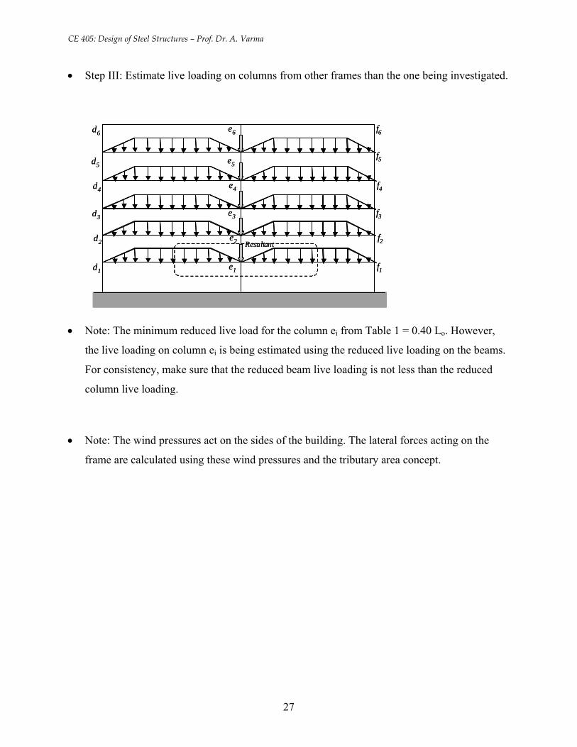
• Step III: Estimate live loading on columns from other frames than the one being investigated.
d1 e1 f1
d2 e2 f2
d3 e3 f3
d4 e4 f4
d5 e5f5
d6 e6 f6
Resultant
d1 e1 f1
d2 e2 f2
d3 e3 f3
d4 e4 f4
d5 e5f5
d6 e6 f6
Resultant
• Note: The minimum reduced live load for the column ei from Table 1 = 0.40 Lo. However,
the live loading on column ei is being estimated using the reduced live loading on the beams.
For consistency, make sure that the reduced beam live loading is not less than the reduced
column live loading.
• Note: The wind pressures act on the sides of the building. The lateral forces acting on the
frame are calculated using these wind pressures and the tributary area concept.
27
CE 405: Design of Steel Structures – Prof. Dr. A. Varma
ASCE 7 – 98 pg. 39
28
CE 405: Design of Steel Structures – Prof. Dr. A. Varma
Figure showing the Wind Speed of Eastern US. (ASCE 7 – 98 pg. 35)
29
CE 405: Design of Steel Structures – Prof. Dr. A. Varma
ASCE 7 – 98 pg. 41
30
CE 405: Design of Steel Structures – Prof. Dr. A. Varma
ASCE 7 – 98 pg. 43
31
CE 405: Design of Steel Structures – Prof. Dr. A. Varma
ASCE 7 – 98 pg. 42
32
CE 405: Design of Steel Structures – Prof. Dr. A. Varma
Importance factor ASCE 7 – 98 pg. 55
wind directionality factor asce 7 – 98 pg.
33
CE 405: Design of Steel Structures – Prof. Dr. A. Varma
velocity pressure exposure coefficient
34
CE 405: Design of Steel Structures – Prof. Dr. A. Varma
internal pressure coefficient for buildings
35


![Manipulating Band Structure through Reconstruction of ......engineering,such as energy filtering,[6] resonant level,[7] and/ or diminishing k via structural engineering,asexemplified](https://img.pdfslide.tips/doc/110x75/6036caf35d21eb7ce52cf755/manipulating-band-structure-through-reconstruction-of-engineeringsuch-as.jpg)