Embed Size (px)
Citation preview

8/3/2019 10135
http://slidepdf.com/reader/full/10135 1/13
( Reaffirmed 1997 )

8/3/2019 10135
http://slidepdf.com/reader/full/10135 2/13
IS:10135 - 1985
Indian Standard
CODE OF PRACTICE FOR
DRAINAGE SYSTE M FOR GRAVITY DAMS,
THE IR FOUNDATIONS AND ABUTMENTS
( First R evision )
Dams ( Overflow and Non-overflow ) Sectional Committee, BDC 53
Chuirman
SHRI V. B. PATEL
Representing
Irr igation Departmen t, Government of Gujar at,Gandhinagar
Members
SHRI R. K. BHASIX Bhakra Beas Management Boar d, Nan gal Township
SHRI J . S. KH URANA ( Altcrn alc )SERI H. S. BOAT In per sonal capacity ( No. 599, 10th Cross, Jayanagar,
Bangalore )SHILI M. V. BRAISE Tata Consu lting En gineer s, Ban galore
SBRI R. SIVASANKAR ( Alternate )SHRI B. K. CHADHA Consu lting En gineering Services ( India ) Private
Ltd, New DelhiP~OF HARI KRISHNA ( Alternate )
PROF M. C. CHATURVEDI India n Ins titu te of Techn ology, New Delhi
CHIEF ENGINEE R, THEIN DAM Irrigation Department, Govern men t of Pu njab,
DESIGN ChandigarhDIRE CTOR ( DAM ), TRE IN DAM
DESIGN ( Alternate )SHRI C. ETTY DARWIN In personal capacity ( Muttada P. O., Trivandrum )SHRI B. Dass Irr igation and Waterways Departmen t, Government
of West Bengal, CalcuttaDIRECTOR Central Water a nd Power Resear ch Station, Pun e
SHRI S. L. MOKHASRI ( Alternate )DIRECTOR ( E&RDD-I ) Centr al Water Commission, New Delhi
DEP UTY DIRE CTOR ( E&RDD-I ) ( Alternate )DIRECTOR, INSTITUTE OF HYDRA- Pu blic Works Depart men t, Governm ent of Tamil
ULICS & HYDROLOGY, P OONDI Nadu, MadrasSUPIRINTENDINQENGINEER
SHRI MD~;rts ,‘,~~~$cte 1. . . Hindu sta n Const ru ction Compa ny Ltd, Bombay
SHRI K. MADHAVAN Centr al Water Comm ission, New Delhi
DIRE CTOR ( C&MDD-I ) ( Alternate )
( Continued on page 2 )
@ C@yright1986
INDI AN STANDARDS INSTI TUTION1
This publicat ion is protected un der th e Zndian Copyright Act ( XIV of 1957 ) andreproduction in whole or in part by any means except with written permission of thepublisher sha ll be deemed to be an infringemen t of copyright un der th e said Act. I
8/3/2019 10135
http://slidepdf.com/reader/full/10135 3/13
IS :10135 1985
( Continued ffam age 1 )
Members Representing
SHRI S.P. MATHUR Major, Medium and Minor Irrigation Department,Government of Madhya Pradesh, Bhopal
SHRI A. M. NAYAK (Alternate )SHRI RAMABHADRAN NAIR Kerala State Electricity Board, TrivnndrumOFFICER-ON-SPECIAL DUTY, Irrigation Department, Government of Andhra
APERL Pradesh, HyderabadSUPERINTENDINGENQINEER
( DAMS ) ( CD0 ) ( Alternate )SHRI RAM IQBAL SINUH Irrigation Department, Government of Uttar
Pradesh, LucknowSHRI BISHAM LAL JATANA ( Alternate )
SHRI T. RAN~ANNA Karnataka Power Corporation Ltd, BangaloreREPRESENTATIVE Institution of Engineers ( India ), Calcutta
SECRETARYDIRECTOR ( CIVIL ) ( Alternate ) Central Board of Irrigation and Power, New Delhi
S~ERINTENDIN~ ENQINEER Irrigation Department, Government of Guj arat,
(CDO) GandhinagarUNIT LEADER ( C ) ( Alternate )
SUPERINTENDINQENGINEER Irrigation Department, Government of Maharashtra,(MD),CDO Bombay
SHRI G. RAMAN, Director General, IS1 ( Ex-o$rccio Member )Director ( Civ Engg )
DR
SHRI K.K. SHARMA
Joint Director ( Civ Engg ), IS1
Masonry and Concrete Dams Subcommittee, BDC 53 : 1
Convener
B. PANT Water Resources Development Training Centre,University of Roorkee, Roorkee
MembersADDITIONALCHIEF ENGINEER
d ~%?‘%,A.
Irrigation Department, Government of UttarPradesh, Lucknow
Indian Institute of Technologv. New Delhi, ,SHRI R. K. BHASIN Bhakra Beas Management Board, Nangal Township
SHRI K. K. KHOSLA ( Alternate )SHRI H. S. BHAT In personal capacity ( ivo. 599, 10th Cross, Jayanagar,
Bangalore )CHIEF ENGINEER, CD0 Irrigation Department, Government of Andhra
Pradesh, HyderabadOFFICER-ON-SPECIAL DUTY,
APERL ( Alternate )
SHRI C. ETTY DARWIN In personal capacity ( Muttada P. O., Trivaadrum )DIRECTOR I C&MDD-I ) Central Water Commission. New Delhi
DEPCT; DIRECTOR ( C&MDD-I ) ( Alternate )
( Continued on page 12 )
2
8/3/2019 10135
http://slidepdf.com/reader/full/10135 4/13
IS : 10135 1985
Indian Standard
CODE OF PRACTICE FORDRAINAGE SYSTEM FOR GRAVITY DAMS,
THE IR FOUNDATIONS AND ABUTMEN TS
( First Rev ision )
0. FOREWORD
0.1 This Indian Standard ( First Revision ) was adopted by the IndianStandards Institution on 20 November 1985, after the draft finalized byDams ( Overflow and Non-overflow ) Sectional Committee had beenapproved by the Civil Engineering Division Council.
0.2 A dam constructed across any stream disturbs the natural drainage -surface and sub-surface. The seepage water inside the body and founda-tions of the dam should be disposed of to enhance the safety factor ofthe structure. Hence, a well planned drainage system is essential.
0.3 During operation of the dam, a watch should be kept on theprevailing uplift pressures so as to assess the adequacy or otherwise ofthe drainage provided.
0.4 It is necessary to observe and study the quantum of seepage fromvarious sources individually as well as collectively with respect to dataon rainfall, reservoir level, etc, and to take remedial measures in case ofabrupt departures from the normal.
0.5 This standard was first published in 1982. Many technical commentswere received since then. The present revision is being issued to takecare of these comments. Important modifications incorporated in thisrevision include:
4
b)
Provision of water seal to prevent entry of air in drainage holesfor minimizing formation of calcium carbonate and therebyreducing choking of drainage holes; and
Addition of criteria to determine the necessity of providing adrainage gallery.
3

8/3/2019 10135
http://slidepdf.com/reader/full/10135 5/13
IS : 10135 -“I985
1. SCOPE
1.1 This code prescribes general requirements and methods of drainagein and around a gravity dam, its foundations and abutments. It doesnot cover drainage requirements for energy dissipation devices, chutesand training walls. It may be supplemented by specific requirementsto suit the site conditions.
2. CLASSIFICATION
2.1 Drainage is the safe disposal of surface and seepage water in theabutment, foundation and the- body of the dam. The drainage is thusclassified into the following four categories:
a) Surface drainage,b) Sub-surface drainage,
c) Internal drainage of the dam, and
d) Foundation drainage.
Although foundation drainage forms a part of the sub-surfacedrainage, yet for the purpose of this standard, it has been covered undera separate sub-head due to its importance.
3. REQUIREMENTS AND METHO DS OF DRAINAGE
3.1 Surface Drainage - All open surfaces in the vicinity of the damshall be provided with adequate drainage. For this purpose opensurface channels shall be so designed and laid as to drain off the areaeffectively and carry away the surface run-off into the reservoir upstreamof the dam or into the river downstream of the dam. The service roadsand other approach roads leading to dam shall have proper camberand longitudinal slopes for catch water drains. The water from thesecatch drains shall be collected at suitable intervals depending on topo-graphy, rainfall, etc, and led away into the natural drains away from thedam. The roadway, the ducts for electric cable, the crane rail recessesand any other recesses provided at the top of the dam shall be drainedthrough pipes of at least 100 mm diameter.
3.2 Sub-surface Drainage - This shall be provided for the followingpurposes, if necessary:
a) Protection of slopes, and
b) Drainage of abutments.3.2.1 Protection of Slopes - In some river valley projects, the hill slopes
in the vicinity of abutments need to be protected against likely slips.This sh-all be done by either providing a combination of concretecladding/shotcreting and drainage holes or any other suitable
4

8/3/2019 10135
http://slidepdf.com/reader/full/10135 6/13
IS : IO135 - 1985
arrangement or by providing drainage holes only. Provision of non-return
valves, Lvhich allow water to flow towards the reservoir area or hill slopes
in the vicinity of abutment only, shall be made in the drainage holes.
3.2.2 Drainage of Abut ment s - The drainage gallery may be extended
into the abutment rock, together with provision of cross tunnels,as drainage tunnels, if necessary, for ensuring the stability of abutment
blocks or the abutment.
3.3 I n t e r n a l D r a i n a g e o f D a m - Internal drainage of a gravity damu s u a l l y comprises porous concrete drains/formed drains at the contrac-
tion joints and in the body of the dam.
3.3.1 Vertical drains at contraction joints shall be provided to interceptthe seepage water through the joint and such seepage water shall ulti-
mately be let out into the drainage gallery system. For water stops tobe provided reference may be made to ‘Indian Standard code of practicefor water stops at transverse contraction joints in masonry and concrete
dams’ ( under preparation ).
3.3.2 The internal drainage of concrete/masonry dam shall be provid-
ed with 200 mm dia vertical drains or uniformly inclined ( till theymeet the gallery ) at 3 m centre to centre. For masonry dams these
shall be of precast porous concrete while for concrete dams these shall be
formed drains. These shall convey the seepage water through the body
of the masonry/concrete dam to drainage gallery system. Suitable waterseal to prevent entry of air may be provided at the discharge end of thedrainage pipe in the gallery. For masonry dams, the drains shall be of
porous concrete blocks while for concrete dams, they shall be formed
drains.
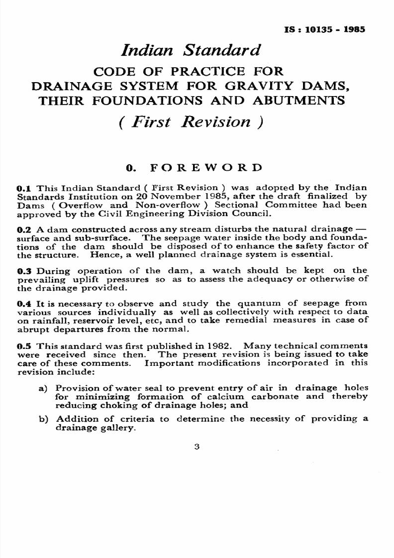
3.3.3 A typical detail of porous concrete drain is shown in Fig. 1. The
porous concrete drain shall conform to the following requirements:
a) The drain shall consist of precast porous concrete blocks of size
400 x 400 x 200 mm with a circular hole of 200 mm dia in themiddle;
b) The porous concrete shall be of 1 : 5 proportion by mass, thatis, one part of cement to 5 parts of 20 to 5 mm size aggregate
( conforming to IS : 383-1970* ); and
c) When tested for permeability with 200 mm thick slab of thisconcrete under a head 100 mm, the discharge shall not be lessthan 30 litres/min/mz.
3.3.4 Formed drains for concrete dams are formed during construc-tion of dam by use of suitable forms.
*Coarse and fine aggregates from natural sources for concrete ( s e c o n d r e v i s i o n .
5

8/3/2019 10135
http://slidepdf.com/reader/full/10135 7/13
M.W.L.--- ---.------____
FR.L.--___-----.
AX!S OFDAM,
WATER STOPSAT JOINTS-
CONNECTION
TO CONTRACT10JOINT TRAPDRAIN
G.L
4
’ OF DAM
*DETAIL A
;I
j
II !
1;-a1cp 200 mm POROUS CONCRETE
II DRAINS/FORMED DRAINS
II @ 3000 mm C/C
11II
VENTILATION PIPE
4 IF PROVIDED)
I-
L&_
II :!JL-CUI~AIN
/I GROUT HOLE
IA
FIG. 1 PO RO USCONCRETEDRAIN/FORMEDDRAIN ( Continued )
8/3/2019 10135
http://slidepdf.com/reader/full/10135 8/13
IS: 1013!5-1985
-OP OF DAM
COUPLING-COUNTERSUNK
_I ..I.*-
CAST IN SITUCEMENT CONCRETE
6 mm THICK STEEL
INTERNAL, 0300
EXTERNAL)WELDED0 STEEL PIPE
POROUS CONCRETEDO x LOO____LOCK 61 .__
WITH A CIRCULARHOLE 9 200
1 B Detail A
All dimensions in millimctres.
FIG. 1 POROUSCONCRETE DRAIN/FORMEDDRAIN
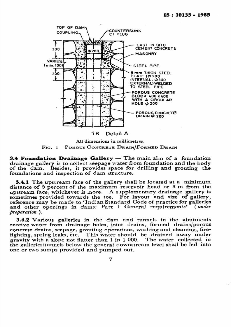
3.4 F o u n d a t i o n D r a i n a g e G a lle r y - The main aim of a foundationdrainage gallery is to collect seepage water from foundation and the bodyof the dam. Besides, it provides space for drilling and grouting thefoundations and inspection of dam structure.
3.4.1 The upstream face of the gallery shall be located at a minimumdistance of 5 percent of the maximum reservoir head or 3 m from theupstream face, whichever is more. A supplementary drainage gallery is
sometimes provided towards the toe. For layout and size of gallery,reference may be made to ‘Indian Standard Code of practice for galleriesand other openings in dams: Part 1 General requirements’ (under
~repardtion ) .
3.4.2 Various galleries in the dam and tunnels in the abutmentsreceive water from drainage holes, joint drains, formed drains/porousconcrete drains, seepage, grouting operations, washing and cleaning, fire-fighting, spring leaks, etc. This water should be drained away undergravity with a slope not flatter than 1 in 1 000. The water collected inthe galleries/tunnels below the general downstream level shall be led intoone or two sumps provided and pumped out.
7

8/3/2019 10135
http://slidepdf.com/reader/full/10135 9/13
IS : 10135 - 1985
3.4.3 Gallery shall invariably be provided in the body of the damwhere height of the structure above normal foundation level is more than10 m ( measured up to crest level in the case of overflow portion of thedam ). For dams with heights below 10 m, the designer should consider
the provision of gallery keeping in view factors like foundation conditionand height of water retained.
3.5 F o u n d a t i o n D r a i n a g e - Foundation drainage provides a means torelieve the uplift under the dam foundations. This drainage is accomp-lished by a line of holes drilled from the foundation gallery into thefoundation rock. The size, spacing and depth of these holes are assumedon the basis of physical characteristics of the foundation rock, foundationcondition and depth of storage of the reservoir. The diameter of thehole is generally J’VX drill which is 75 mm. The spacing of the hole maybe kept as 6 m centre to centre. The depth of the holes may be keptbetween 20 and 40 percent of the maximum reservoir depth and between30 and 75 percent of the curtain grouting depth for preliminarydesign. The actual spacing and depth may be determined on the basisof geological conditions. These should be further reviewed and holesprovided at closer intervals or further deepened on the basis of actualobservations after the reservoir is filled. To facilitate this, additionalnipples/pipes shall be embedded in the gallery concrete. The drainageholes of 75 mm diameter are drilled through 100 mm diameter pipeembedded in the masonry/concrete portion. When drainage holes are
drilled through soft foundations for the drainage of shear zones, faults, etc,a perforated pipe should be placed in the drainage holes and the spacebetween walls of hole and this pipe should be filled with pea gravel. Thisarrangement would avoid caving-in of walls and the holes could begot washed, if required.
3.5.1 Drainage holes should be drilled after all foundation groutinghas been completed within a minimum horizontal distance of 15 m. Thedrainage holes shall be drilled, through the drainage, gallery, throughpreviously installed metal pipe extending down to the foundation rock.Additional drainage holes or curtain grouting shall be provided, if upliftpressures higher than designed values are observed. After drilling, thepipes shall be plugged at top and seepage water from the hole shall betaken off at a T-joint and let to the gutter of gallery ( see Fig. 2 ).
3.5.2 Besides the foundation drainage gallery, the drainage holes shallbe drilled through tunnels in the foundation and abutments, Spacingand depth of the holes shall depend on the geology.
3.5.3 Where cross galleries, additional foundation galleries and driftsare introduced, necessary drainage arrangements should also be
considered and provided.3.5.4 The seepage water from drainage hoies should be monitored
from consideration of quantity, contents of fines and chemicals andremedial action taken, if warranted.
8

8/3/2019 10135
http://slidepdf.com/reader/full/10135 10/13
IS : 10135 - 1985
7
;;
0 STEEL PIPE jj
(1000 LONG)
-y
I!
A
i I--
b 200 POROUS CONCRETE/
FOAM0 ORAINS ‘@ 3000 C/C
/
200x100 REDUCER WITH.
WATER TIGHT PACKING
6 100 HO
0.1. PIPE
0 100 HALFROUNO DRAIN
C loo PERFCRATEDPIPE Ca3000 C/c
1O’APPROX6’ APPROX
Q 200 POROUS CONCRETE/FCRMED DRAINS r@ 3000 c /C
200 xl00 REDUCER WITHWATER TIGHT PACKING
STEEL
GUTTER ._
t---------
/--
______ a. .-_-
-.-
VIEW AA
(ALTERNATIVE NC, 1J
WATER SEAL DETAILS
All dimeruiom in millimetrcs.
y@ 100 BENT PIPE
CONNECTED TOREDUCER BYCOUPLING
@200 POROUS COHCRETE
FORMED DRAINS 8 1000 CfC
200 xl00 REDUCER WITI4WATER TIGHT PACKING
,
Q 100 G.I PIPE
I
1
I *
8’ ,-I
‘.J;_: 1’
DRAINAGEGUTTER
_____-- _______-,_____--
-.
VIEW AA
(ALTERNATIVE No 21
2A Foundation Drainage Gallery ( in Rock )
FIG. 2 Foum~~ioli DRAINAGE GALLERY : Confinitc~ )
9

8/3/2019 10135
http://slidepdf.com/reader/full/10135 11/13
As in the Original Standard, this Page is Intentionally Left Blank

8/3/2019 10135
http://slidepdf.com/reader/full/10135 12/13
IS : 10135 1985
FOI
J
Y_(
+ 56 pB:pACK SfEEL -s’c. *. .
:‘r :”. .I
. .” ;: ;i’. ,,
rGALLERY FLOOR h
PEA-GRAVEL FILLING
(WHERE NECESSARY 1
9 25 PERFORATED PI
ORAINAGE HOLE
26 Foundation Drainage Pipe ( in Soft Foundation
All dimensions in millimetres.
FIQ. FOUNDATION RAINAGE GALLERY
1
8/3/2019 10135
http://slidepdf.com/reader/full/10135 13/13
IS :10135- 1985
( Continued rom page 2 )
Members
DIRE CTOR ( T&P )
Reprercnting
Irr igation Departm ent, Governmen t of Pun jab,Chandigarh
DIRE CTOR ( SPILLWAY & POWERPLANW ) ‘( Alternate )DR A. K. MULLICK Cement Resear ch Institut e of India, New Delhi
SHRI N. K. JAIN ( Altrmatc )SHRI RAMABRADRAN NAIR KeraIa Sta te Electr icity Boar d, Trivandr um
SHRI M. P. BH ARATHAN ( Alternate )SUPERINTENDINQ NGINEER,CD0 Irrigation Departm ent, Governmen t of Gujar at,
GandhinanarUN IT LE WDER ( C ) ( AZtcmatc )
SUPERINTENDINQ N QINEER( MD ), CD0
SHRI P. R. TONQONKAR
Irr igat ion Departm ent, Governmen t of Mahar nshtr a,Bombay
In persona l capa city ( Shirsh Co-obsratiuc Housing
Society, Veer Savarkar Marg, Bombay )
12


![[M-10135]AnalogDiscovery2アナログ回路万能測定ツール · 2020. 4. 9. · [M-10135]AnalogDiscovery2アナログ回路万能測定ツール ※ ※通販センター・秋葉原店・八潮店、全拠点の合計台数50台限りとなります。](https://img.pdfslide.tips/doc/110x75/60f05f8bb33dd945be7f12cb/m-10135analogdiscovery2ffeeffff-2020-4-9-m-10135analogdiscovery2ffeeffff.jpg)