Embed Size (px)
Citation preview

11
K. Yamamoto, R. Takahashi, T. Sekiguchi, Y. Sakakibara, C. Tokoku, M. Kamiizumi, U. Iwasaki, T. Uchiyama, S. Miyoki, M. Ohashi, T. AkutsuA,
H. IshizakiA, T. SuzukiB, N. KimuraB, S. KoikeB, K. TsubonoC, Y. AsoC, T. UshibaC, K. ShibataC, D. ChenD, N. OhmaeE, K. SomiyaF, R. DeSalvoG,
E. MajoranaH, W. JohnsonI, KAGRA collaboration
ICRR.UT, NAOJA, KEKB, Phys.S.UTC, Astro.S.UTD, E.UTE,S.TITF, Sannio Univ.G, INFNH, Louisiana State Univ.I
Development of cryogenic payload
for KAGRA I
2012 September 11The meeting of Physical Society of Japan@Kyoto Sangyo University, Kyoto, Kyoto
2
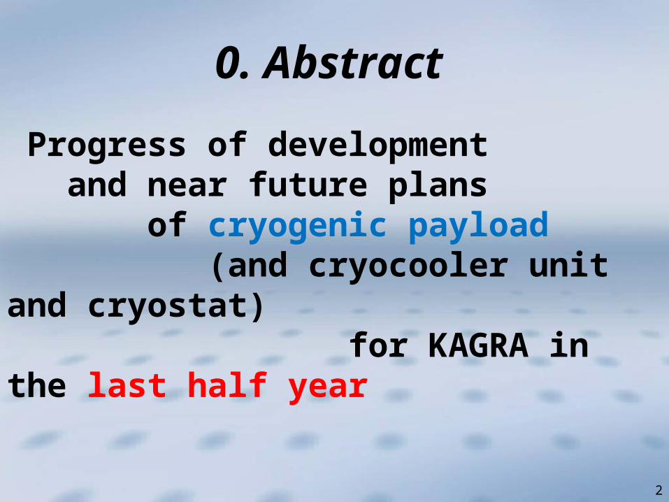
0. Abstract
Progress of development and near future plans of cryogenic payload (and cryocooler unit and cryostat) for KAGRA in the last half year
3
Contents
1.Introduction2.Cryocooler unit3.Cryostat4.Cryogenic payload5.Summary
4
1. Introduction KAGRA :2nd generation interferometric gravitational wave detector in Japan
Key features of KAGRA projectSilent underground site (Kamioka) : Small seismic motion Cryogenic system : Reduction of thermal noise and so on
5
1. Introduction
55
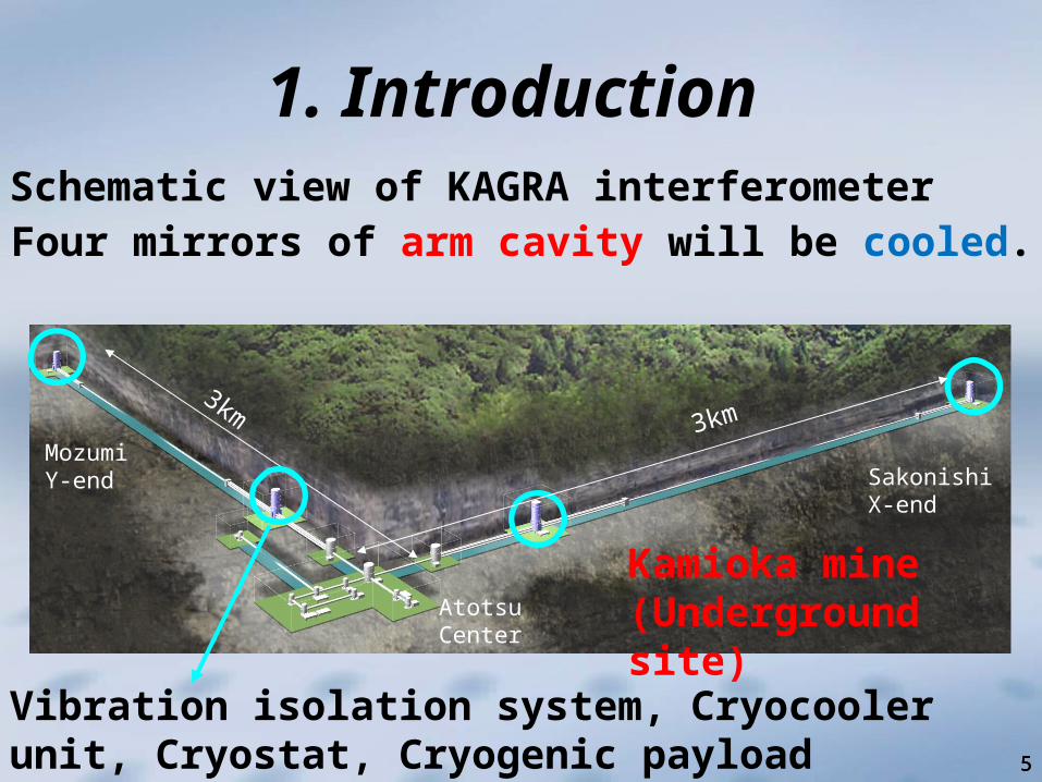
3km3km
MozumiY-end Sakonishi
X-end
AtotsuCenter
Vibration isolation system, Cryocooler unit, Cryostat, Cryogenic payload
Schematic view of KAGRA interferometerFour mirrors of arm cavity will be cooled.
Kamioka mine (Underground site)
1. Introduction
6
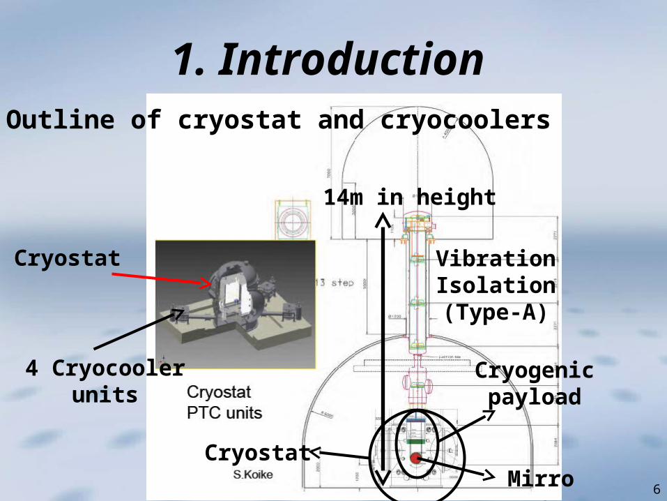
Outline of cryostat and cryocoolers
14m in height
Cryostat
Vibration Isolation(Type-A)
Cryogenic payload
Mirror
Cryostat
4 Cryocooler units

7
to SAS
View ports
Remote valve unit
4 Low vibration cryocooler unit
Main LASER beam
2.6m~
3.6
m
Cryostat Stainless steel t20mm Diameter 2.6m Height ~3.6m M ~ 10 ton
Cryo-coolers Pulse tube, 60Hz 0.9 W at 4K (2nd) 36 W at 50K (1st)
Outline of cryostatCryogenic
payload
Mirror
1. Introduction
88
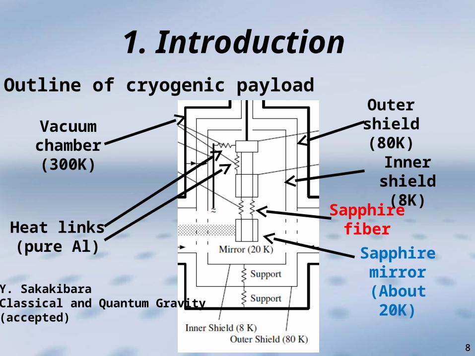
Outline of cryogenic payload
Sapphire fiber
Sapphire mirror
(About 20K)
Inner shield(8K)
1. Introduction
Y. SakakibaraClassical and Quantum Gravity (accepted)
Outer shield(80K)
Heat links(pure Al)
Vacuum chamber
(300K)
9
2. Cryocooler unit
99
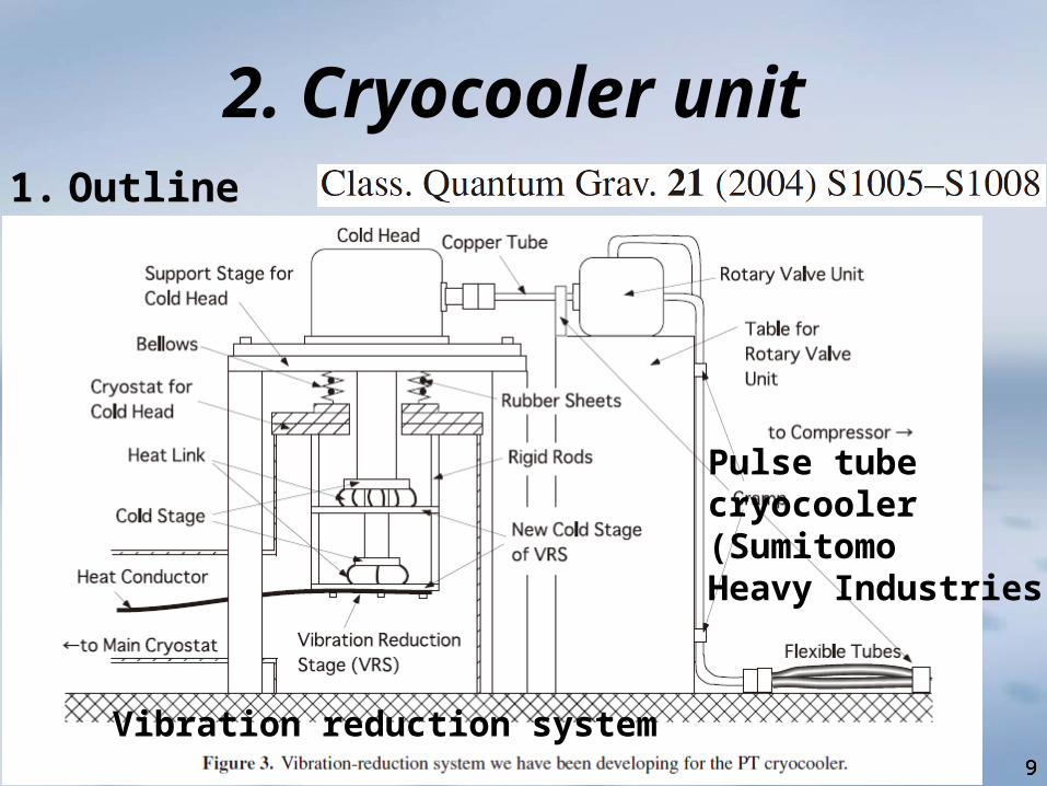
1. Outline
Pulse tube cryocooler(Sumitomo Heavy Industries)
Vibration reduction system

10
2. Cryocooler unit
1010
2. Drawing by Jecc Torisha
Pulse tube cryocooler
Heat conductor
Cryostat

2. Cryocooler unit
11
3. Cooling test : Cryocooler works well.
2nd head6.9 K (2.5 W heat load)1st head49.3 K (25 W heat load)
Y. Sakakibara’s talk

1212
2. Cryocooler unit 4. Vibration measurement
Pulse tube cryocooler
Heat conductor
Cryostat
Vibration of this part was measured.
13
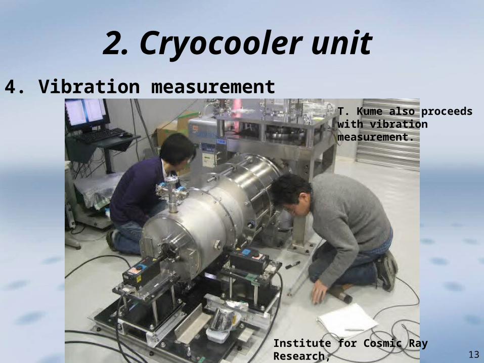
2. Cryocooler unit 4. Vibration measurement
Institute for Cosmic Ray Research, the University of Tokyo
T. Kume also proceeds with vibration measurement.

14
2. Cryocooler unit 4. Vibration measurement
Displacement sensor
15
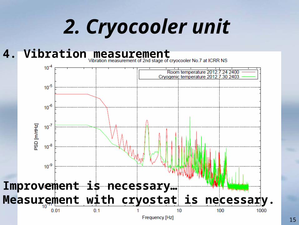
2. Cryocooler unit 4. Vibration measurement
Improvement is necessary…Measurement with cryostat is necessary.
16
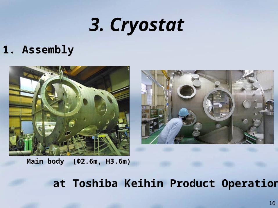
3. Cryostat 1. Assembly
at Toshiba Keihin Product Operations
Main body (Φ2.6m, H3.6m)
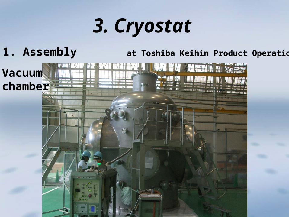
3. Cryostat 1. Assembly at Toshiba Keihin Product Operations
Vacuumchamber
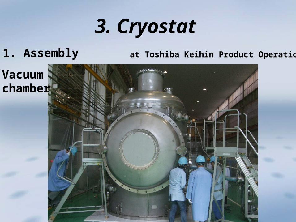
3. Cryostat 1. Assembly at Toshiba Keihin Product Operations
Vacuumchamber
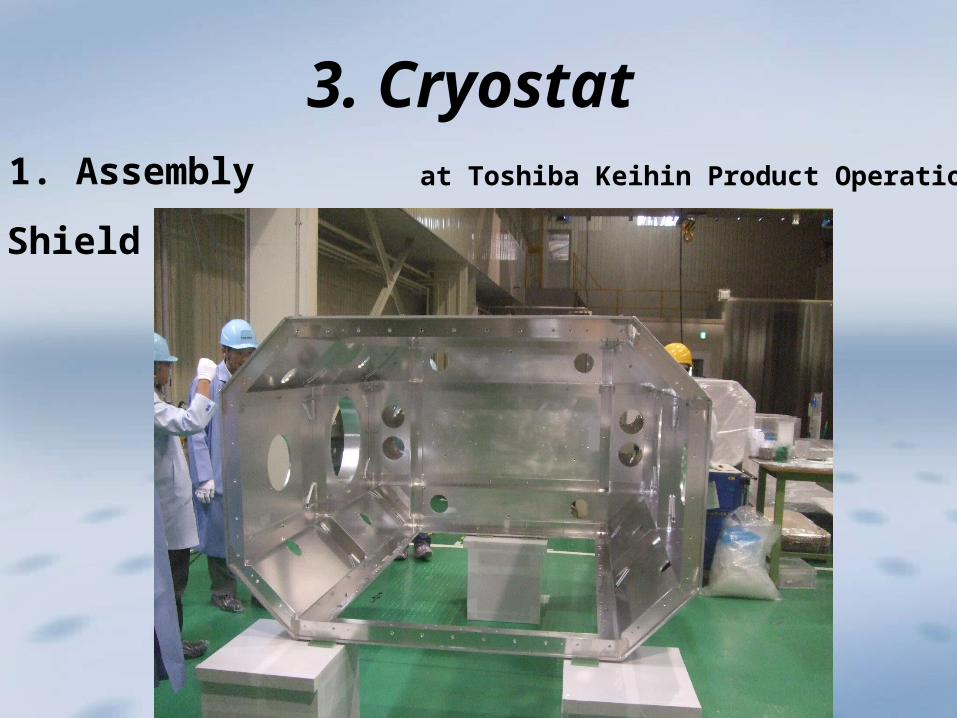
3. Cryostat 1. Assembly at Toshiba Keihin Product Operations
Shield

3. Cryostat
20
2. Experimental plans in Toshiba
In this autumn, there will be cooling test of shileds in Toshiba Keihin Product Operations.
At the same time, we have experimental plans in Toshiba.
(1) Heat load test(2) Measurement of vibration of shield(3) Measurment of initial cooling time

21
Vibration of shield could be problems. Vibration via heat links, Scattered lightThis measurement is at cryogenic temperature and in vacuum.
Luca Naticchioni (Rome) and Dan Chen will measure vertical and horizontal vibration of radiation shield of KAGRA in cooling test, respectively.
D. Chen’s talk
2. Experimental plans in Toshiba (2) Measurement of vibration of shield
3. Cryostat
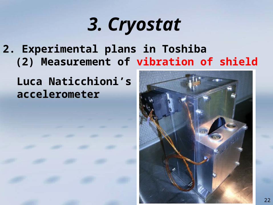
22
Luca Naticchioni’s accelerometer
2. Experimental plans in Toshiba (2) Measurement of vibration of shield
3. Cryostat
23
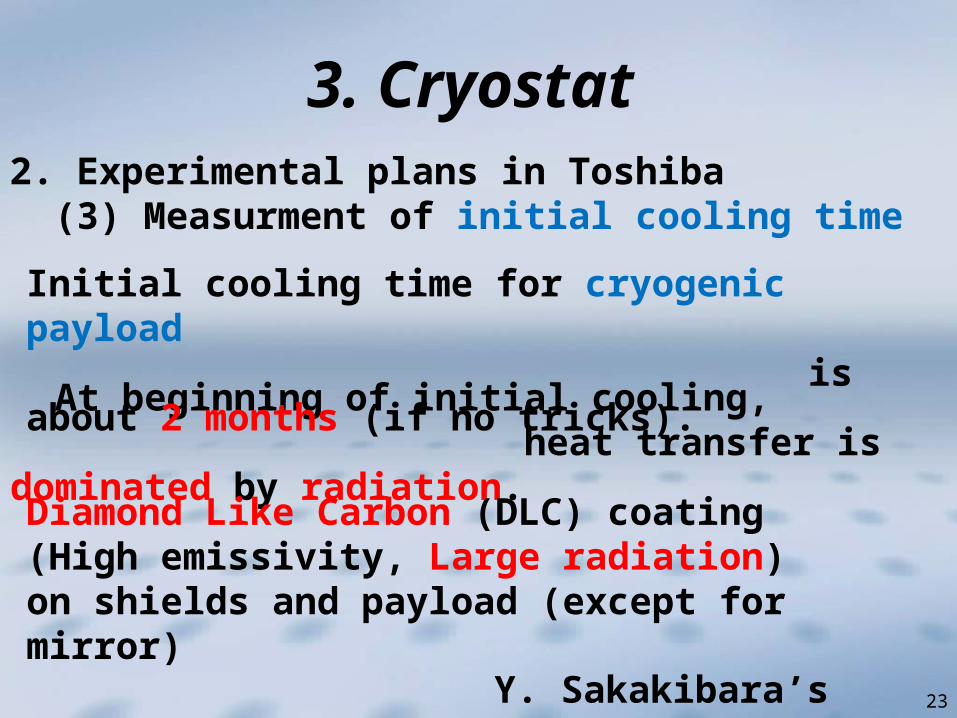
At beginning of initial cooling, heat transfer is dominated by radiation.
Initial cooling time for cryogenic payload is about 2 months (if no tricks).
Diamond Like Carbon (DLC) coating (High emissivity, Large radiation) on shields and payload (except for mirror)
Y. Sakakibara’s talk
2. Experimental plans in Toshiba (3) Measurment of initial cooling time
3. Cryostat
24
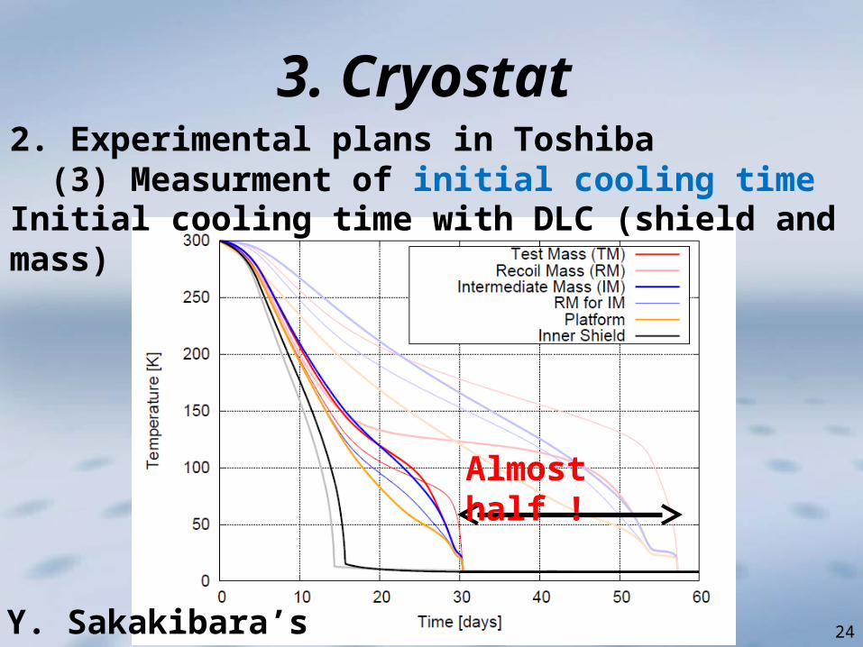
Initial cooling time with DLC (shield and mass)
Y. Sakakibara’s talk
Almost half !
2. Experimental plans in Toshiba (3) Measurment of initial cooling time
3. Cryostat

25
We must check the effect of radiation (and DLC coating) on the initial cooling time experimentally.
We suspend something without heat link inside shield and monitor the temperature of something in shiled during cooling test.
What is something ?Sample 1 : Sapphire and metal hollow sphere Sample 2 : Dummy payload (hollow masses)
2. Experimental plans in Toshiba (3) Measurment of initial cooling time
3. Cryostat
26
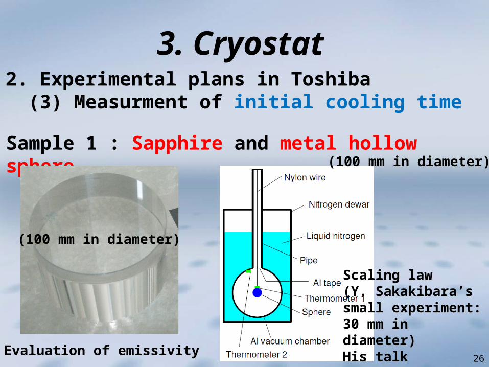
Sample 1 : Sapphire and metal hollow sphere
2. Experimental plans in Toshiba (3) Measurment of initial cooling time
Evaluation of emissivity
Scaling law (Y. Sakakibara’s small experiment: 30 mm in diameter)His talk
(100 mm in diameter)
(100 mm in diameter)
3. Cryostat

27
Sample 2 : Dummy payload (hollow masses)
2. Experimental plans in Toshiba (3) Measurment of initial cooling time
Half sizeHollow masses (~5 kg)DLC coatingSapphire bulk as dummy mirror
Preparation is in progress.
3. Cryostat
28
4. Cryogenic payload1. Mechanical simulation T. Sekiguchi is developing.
(1) Vibration via heat links (above 1 Hz) (2) Thermal noise (above 10Hz) (3) Control scheme (Investigation started recently)
29
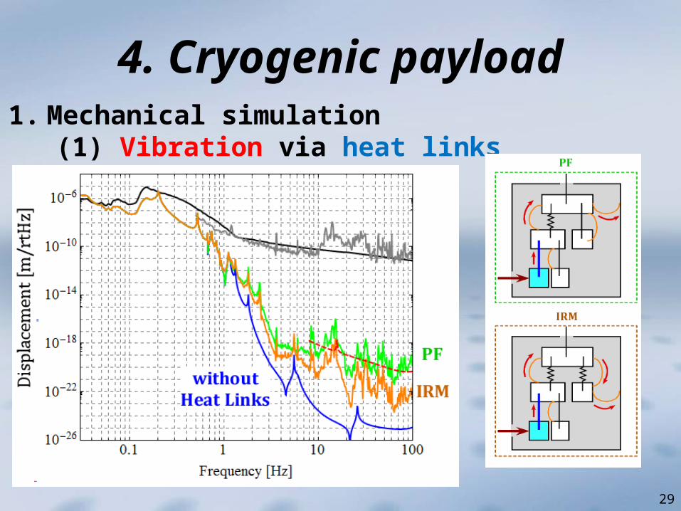
1. Mechanical simulation (1) Vibration via heat links
4. Cryogenic payload
30
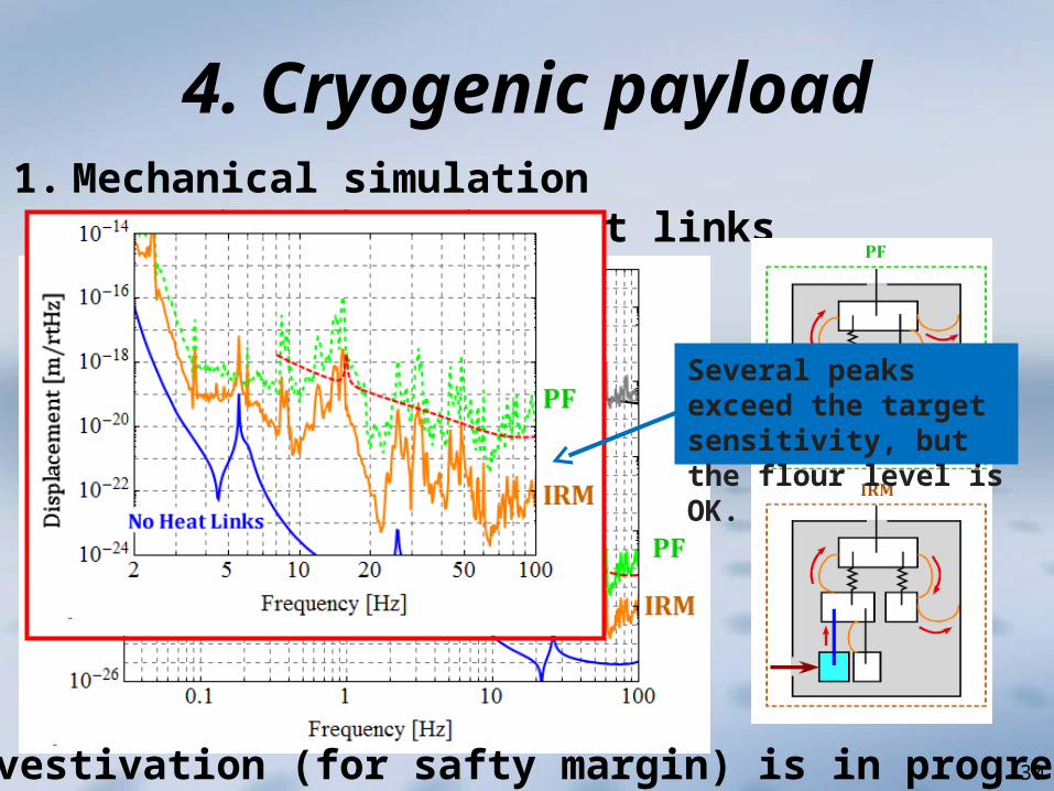
1. Mechanical simulation (1) Vibration via heat links
Several peaks exceed the target sensitivity, but the flour level is OK.
Investivation (for safty margin) is in progress.
4. Cryogenic payload
31
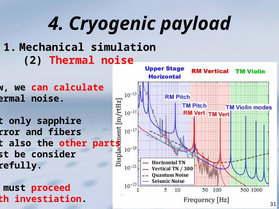
1. Mechanical simulation (2) Thermal noise
Now, we can calculate thermal noise.
Not only sapphire mirror and fibersbut also the other parts must be consider carefully.
We must proceed with investiation.
4. Cryogenic payload
32
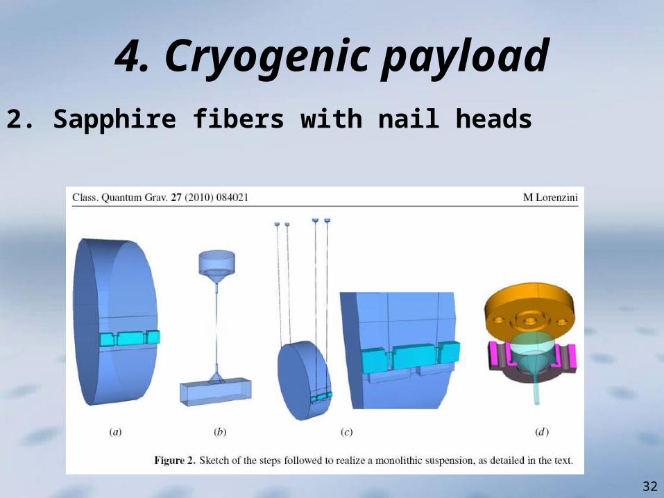
2. Sapphire fibers with nail heads
4. Cryogenic payload
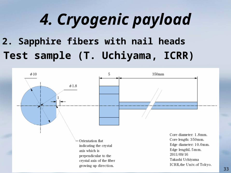
33
Test sample (T. Uchiyama, ICRR)
2. Sapphire fibers with nail heads
4. Cryogenic payload
3434
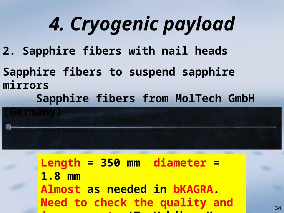
Length = 350 mm diameter = 1.8 mm Almost as needed in bKAGRA.Need to check the quality and improvement (T. Ushiba, K. Shibata).
2. Sapphire fibers with nail heads
Sapphire fibers to suspend sapphire mirrors Sapphire fibers from MolTech GmbH (Germany)
4. Cryogenic payload
3535
Ettore Majorana (Rome) asked IMPEX HighTech GmbH (German company).
They can make similar fibers (nail heads on the both ends).
Shoter fibers (about 100 mm in length) is coming soon.
4. Cryogenic payload2. Sapphire fibers with nail heads

3636
Thermal conducutivity measurement : T. Ushiba
Q-value measurement in this autumn: K. Shibata and Y. Sakakibara
4. Cryogenic payload2. Sapphire fibers with nail heads
3737
5. Summary1. Tests for cryocooler unit Cooling : OK Vibration : Almost OK (some improvement is necessary)
2. Cryostat Assembly is in progress in Toshiba. In this autumn, there will be cooling test of shileds. In this test, we will try these experiments (1) Heat load test (2) Measurement of vibration of shield (3) Measurment of initial cooling time

3838
5. Summary3. Cryogenic payload Simulation tool Vibration via heat link Thermal noise Control scheme Investigation using simulation tool is in
progress.
Sapphire fibers with nail heads Moltech and IMPEX Measurement of thermal conductivity and Q-values is in progress.

39
Thank you for your attention !

4040
4. Challenges for cryogenic
40
1. Issues of cooling : Reduction of heat load (Scattering on mirror)Scattering on mirror : 10 ppm ? Scatted power is 5 W in radiation shield !
Cryostat scheme 4 cryocoolers cool radiation shields. Payload is connected to radiation shield by heat links.If larger scattered light attacks shield, mirror temperature must be higher.

4141
4. Challenges for cryogenic
41
1. Issues of cooling : Reduction of heat load (Scattering on mirror)Scattering on mirror : 10 ppm ? Scatted power is 5 W in radiation shield !
New cryostat scheme 2 cryocoolers cool radiation shields. Other 2 cryocoolers cool payload via separated heat path. Even if large scattered light attacks shield, mirror temperature could be low.
4242
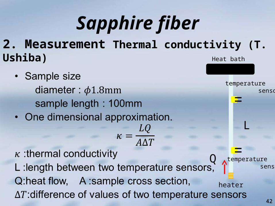
Sapphire fiber
L
temperature sensor
temperature sensor
heater
Q
Heat bath
2. Measurement Thermal conductivity (T. Ushiba)

4343
Sapphire fiber
L
temperature sensor
temperature sensor
heater
Q
Heat bath
2. Measurement Thermal conductivity (T. Ushiba)
temperaturesensor
heater
heat bath
4444
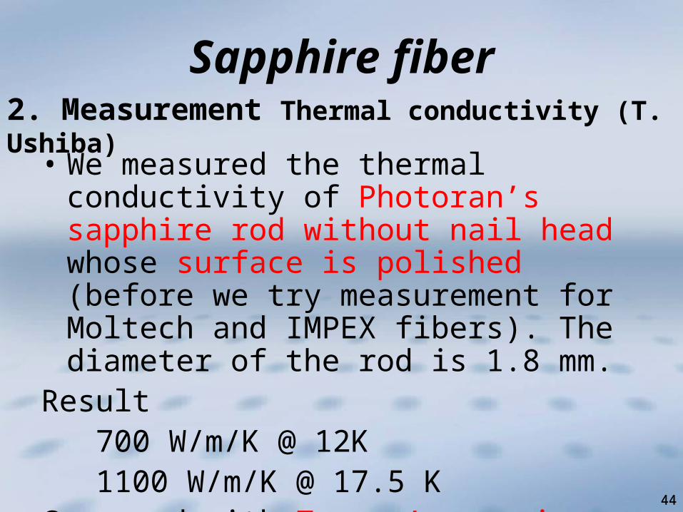
Sapphire fiber2. Measurement Thermal conductivity (T. Ushiba)
• We measured the thermal conductivity of Photoran’s sapphire rod without nail head whose surface is polished (before we try measurement for Moltech and IMPEX fibers). The diameter of the rod is 1.8 mm.
Result 700 W/m/K @ 12K 1100 W/m/K @ 17.5 KCompared with Tomaru’s previous
measurement, our result is a bit small.
4545
Sapphire fiber2. Measurement Thermal conductivity (T. Ushiba)
Something to be considered as the reason why the value of this measurement is small
•the purity of the sapphire rod
So, we now measure thermal conductivity near 30 K (the peak of sapphire thermal conductivity) and confirm the purity is well or not.
If the purity of sapphire rod is not enough well, the peak of the thermal conductivity is gentle.

4646
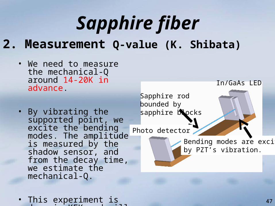
Sapphire fiber2. Measurement Q-value (K. Shibata)
Moltech Sapphire rod φ1.8mm• In KAGRA, we use
sapphire rods to suspend mirrors.
• The mechanical-Q of its bending modes are high. But it may depends on the surface condition.e.g.) as grown or polished, what manufactured it.
4747
Sapphire fiber2. Measurement Q-value (K. Shibata) • We need to measure the
mechanical-Q around 14-20K in advance.
• By vibrating the supported point, we excite the bending modes. The amplitude is measured by the shadow sensor, and from the decay time, we estimate the mechanical-Q.
• This experiment is done in KEK and will be finished by the end of this summer.
Sapphire rod bounded by sapphire blocks
Photo detector
In/GaAs LED
Bending modes are excitedby PZT’s vibration.

4848
4. Challenges for cryogenic 2. Issues of noise : Vibration via heat links
Calculation by T. Sekiguchi(Details are in his talk on Tuesday)
T. Sekiguchi’s Master thesis (English)http://gwdoc.icrr.u-tokyo.ac.jp/cgi-bin/private/DocDB/ShowDocument?docid=770
4949
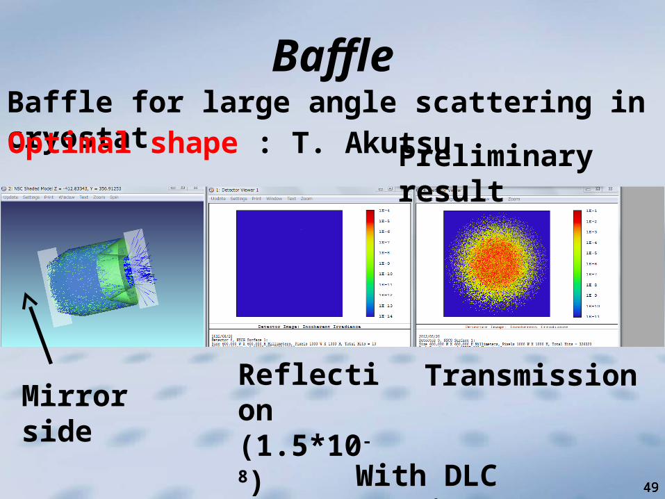
Baffle
4949
Baffle for large angle scattering in cryostat Optimal shape : T. Akutsu
Reflection(1.5*10-8)
TransmissionMirror side
With DLC coating
Preliminary result
50
(1)How to assemble Details of construction, clean room ….
(2)Strength Tensile strength, development of clamp, …
(3)Control system Actuators (what and where), resonant mode (frequency and Q)
2. Issues
51
(4)Cooling
Temperature of mirror, initial cooling time, heat resistance …
(5)Noise
Thermal noise, vibration via heat links …
2. Issues
52
Cryogenic payload : One of key features of LCGT projectCryogenic part of seismic isolation system
Cryostat installation in ICRR (Kashiwa) ~2013.3 (Check of cryostat system)
Check of cryogenic payload in ICRR
Preparation is in progress. (1)Thermal simulation (2)Sapphire fiber-mirror connection (3)Simulation of effect of external vibration (with heat link) (4)Thermal noise
4. Summary
53
(1)How to assemble Details of construction, clean room ….
(2)Control system Actuators (what and where), resonant mode (frequency and Q)
5. Future work


![CPDLViolino [I] T T T T ˝ ‘ Violino [II] T ˝ ‘ ‘ • ‘ ˝ ˝ ‘ Cornetto [I] T T T T ˝ ‘ Cornetto [II] T ˝ ‘ ‘ • ‘ ˝ ˝ ‘ Cornetto [III] T T T](https://img.pdfslide.tips/doc/110x75/603c519bcaf49e6c0f1d3476/violino-i-t-t-t-t-a-violino-ii-t-a-a-a-a-a-cornetto.jpg)