Embed Size (px)
Citation preview
05/02 2CDC126001M1001MontageanweisungInstallation InstructionsNotice d’installation
Istruzioni per il montaggioInstrucciones de montaje
AC 010
16540502_BRANDLABEL.FM Seite 1 Montag, 15. Januar 2007 9:15 09
Lebensgefahr durch elektrischen Strom! Nur Elektrofachkräfte und elektrotechnisch unterwiesene Personen dürfen die im Folgen-den beschriebenen Arbeiten ausführen.
Die Stromversorgungsgeräte sind Einbaugeräte. Beachten Sie für die Installation der Geräte die länderspezifischen Vorschriften.
Electric current! Danger to life! Only skilled or instructed persons may carry out the following operations. The power supply units are mounting devices. The national regulations/ specifications must be observed for the installation of the devices.
Tension électrique dangereuse ! Seules les personnes qualifiées et averties doivent exécuter les travaux ci-après. Les blocs d’alimentation sont des appareils faisant partie intégrante d’une installation. Veuillez respecter les normes de mise en œuvre spécifiques aux différents pays.
Tensione elettrica: Pericolo di morte! Solo persone abilitate e qualificate possono eseguire le operazioni di seguito riportate. Gli alimentatori sono unità per montaggio interno. Per l’installazione degli apparecchi è necessario rispettare le normative specifiche di ciascun paese.
¡Corriente eléctrica! ¡Peligro de muerte! El trabajo a continuación descrito debe ser realizado por personas cualificadas y advertidas. Las fuentes de alimentación son aparatos de montaje. Para la instalación de los aparatos han de tenerse en cuenta las normativas/especificaciones a nivel local.
1/12
LM001, ..2, ..3-...ACLM021, .22, .24, .25, .26-...DCLM023-...DC12V
A 2CDC126009M01012CDC126009M0201
ESCOK
DELALT
05/0
2 2C
DC12
6001
M10
01
16540502_BRANDLABEL.FM Seite 2 Montag, 15. Januar 2007 9:15 09
2/12
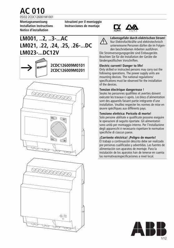
a Spannungsversorgung LM0..-...DC-...24 V DC LM0..-...DC-...12 V DC LM0..-...AC-...90 bis 264 V AC 50/60 Hz
b 8 Eingänge LM0..-...DC-...24 V DC, LM0..-...DC-...12 V DC (2 auch als Analog-Eingänge 0 bis 10 V nutzbar) LM0..-...AC-...0 bis 264 V AC
c DEL-Taste Löschen von Kontakten/Relais/ Verbindungen/leerem Strompfad
d ALT-Taste Verbindungen zeichnen Umschalter: Kontakt = Schließer oder Öffner Strompfad einfügen
e Cursortasten: rechts, links, oben, unten Kontakte, Relais, Nummer wählen P-Taste an: Eingang P1 -> Cursor links
Eingang P2 -> Cursor oben Eingang P3 -> Cursor rechts Eingang P4 -> Cursor unten
f OK-Taste Menü weiterschalten, Aktion übernehmen
g ESC-Taste Ein Menü zurück Menü, Parameter Funktionsrelais verlassen Verlassen ohne Speichern
h Schnittstelle (mit Abdeckung) Steckplatz für Speicherkarte Buchse für PC-Schnittstellenkabel
i Kontakte Ausgängej Gerätekennzeichnungsschildk LCD
Zustandsanzeige der Ein-/Ausgänge Betriebszustände Schaltplan Anzeige der Uhr (nur bei Typen mit „C“)
l Power/Run-LED
a Voltage supply LM0..-...DC-...24 V DC LM0..-...DC-...12 V DC LM0..-...AC-...90 to 264 V AC 50/60 Hz
b 8 Inputs LM0..-...DC-...24 V DC, LM0..-...DC-...12 V DC (2 can also be used as 0 to 10 V analog inputs) LM0..-...AC-...0 to 26/4 V AC
c DEL button Delete contacts/relays/connections/ empty current path
d ALT button Draw connection Toggle between make or break contact Insert current path
e Cursor buttons: right, left, up, down Select contacts, relays, numbers P button on: Input P1 -> Cursor left
Input P2 -> Cursor up Input P3 -> Cursor right Input P4 -> Cursor down
f OK button Enter menu, accept action
g ESC button One menu back Exit function relay parameter menu without saving
h Interface (with cover) Slot for memory card Socket for PC interface cable
i Contacts, outputsj Device labelk LCD
I/O status display Operating states Circuit diagram Display of clock (only with types with “C“)
l Power/Run LED
a b
l
h
i
j
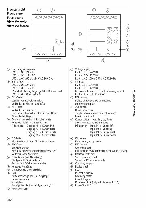
FrontansichtFront viewFace avantVista frontaleVista de frente
a b
cd
h
i
j
k
gf
e
DEL ALT
ESC OK
16540502_BRANDLABEL.FM Seite 3 Montag, 15. Januar 2007 9:15 09
3/12
05/0
2 2C
DC12
6001
M10
01a Alimentation
LM0..-...DC-...24 V CC LM0..-...DC-...12 V CC LM0..-...AC-...90 à 264 V CA 50/60 Hz
b 8 Entrées LM0..-...DC-...24 V CC, LM0..-...DC-...12 V CC (dont 2 utilisables comme entrées analogiques 0 à 10 V) LM0..-...AC-...0 à 264 V CA
c Touche DEL Effacement des objets (contacts, relais, liaison, circuits de courant vides) au niveau de la position du curseur
d Touche ALT Dessiner les liaisons Inverseur : contact = contact F ou contact O Insérer circuit de courant
e Touches de direction : droite, gauche, haut, bas Sélectionner opérandes et indices (contacts, relais, numéro) Affectation des touches entrée P : entrée P1 -> curseur gauche entrée P2 -> curseur haut entrée P3 -> curseur droite entrée P4 -> curseur bas
f Touche OK Niveau menu, exécuter la fonction
g Touche ESC Retour au menu précédent Quitter le niveau « Entrée du programme » Quitter sans enregistrer
h Interface (avec capot) Emplacement pour carte mémoire Connecteur femelle pour câble d’interface PC
i Contacts de sortiej Etiquette de repérage de l’appareilk LCDl Tension d’alimentation/DEL RUN
a Tensione di alimentazione LM0..-...DC-...24 V DC LM0..-...DC-...12 V DC LM0..-...AC-...90 a 264 V AC 50/60 HZ
b 8 Ingressi LM0..-...DC-...24 V DC, LM0..-...DC-...12 V DC (2 utilizzabili anche come ingressi analogici 0 a 10 V) LM0..-...AC-...0 a 264 V AC
c Tasto DEL Cancellazione di contatti, relè, collegamenti, circuiti di corrente vuoti
d Tasto ALT Disegno dei collegamenti Commutatore: contatto = chiusura/apertura Inserisci/cancella riga, circuito di corrente
e Tasti cursore, destra, sinistra, su, giù Selezione contatti, relè, numeri Tasto P a: lato P1 -> cursore a sinistra
lato P2 -> cursore su lato P3 -> cursore a destra lato P4 -> cursore giù
f Tasto OK Menu successivo, conferma azione
g Tasto ESC Menu precedente Esci dal menu, parametro relè di funzione Esci senza salvare
h Interfaccia (con copertura) Posizione di inserimento per la scheda di memoria Connettore femmina per cavo di interfaccia PC
i Uscite contattij Targhetta per il nome dell’apparecchiok LCD
Visualizzazione di stato degli ingressi/uscite Stati di funzionamento Schema a contatti Visualizzazione dell’ora (solo per i tipi con “C“)
l LED Power/Run
a Tensión de alimentación LM0..-...DC-...24 V DC LM0..-...DC-...12 V DC LM0..-...AC-...90 a 264 V AC 50/60 Hz
b 8 Entradas LM0..-...DC-...24 V DC, LM0..-...DC-...12 V DC (2 también pueden utilizarse como entradas analógicas de 0 a 10 V) LM0..-...AC-...0 a 264 V AC
c Tecla DEL Borrar contactos/relés/conexiones/circuito de corriente en vacío
d Tecla ALT Diseñar conexiones Accionamiento del interruptor basculante (toggle) entre contacto de apertura o de cierre Insertar circuito de corriente
e Teclas de cursor: derecha, izquierda, arriba, abajo. Selección de contactos, relés, números Tecla P sobre: Entrada P1 -> Cursor izquierda
Entrada P2 -> Cursor arriba Entrada P3 -> Cursor derecha Entrada P4 -> Cursor abajo
f Tecla OK Entrar menú, aceptar acción
g Tecla ESC Un menú hacia atrás Salir del menú de parámetros del módulo lógico Salir sin archivar
h Interface (con tapa) Slot para tarjeta de memoria Hembrilla para cable de interface a PC
i Contactos, salidasj Etiqueta de características del aparatok LCD
Visualizador de estado ABIERTO/CERRADO Estados operativos Esquema de circuitos Display del reloj (sólo con tipos con “C“)
l Cierre/LED de funcionamiento
05/0
2 2C
DC12
6001
M10
01
16540502_BRANDLABEL.FM Seite 4 Montag, 15. Januar 2007 9:15 09
4/12
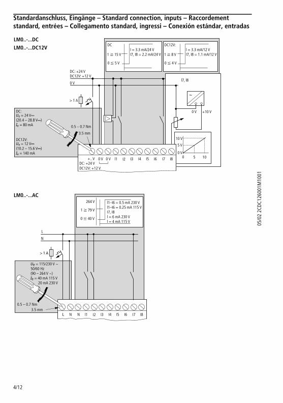
Standardanschluss, Eingänge – Standard connection, inputs – Raccordement standard, entrées – Collegamento standard, ingressi – Conexión estándar, entradas
+10 V
0 V
10 V
5 V
0 V
DC: +24 V+.. V
DC12V: +12 V
h
0 5 10
0 VDC:Ue = 24 VH (20.4 – 28.8 VH)Ie = 80 mA
DC12V:Ue = 12 VH (10.2 – 15.6 VH)Ie = 140 mA
DC: +24 VDC12V: +12 V
0 Vl7, l8
> 1 A
0 V l1 I2 I3 I4 I5 I6 I7 I8
1 f 15 V
0 F 5 V
DCl = 3.3 mA/24 VI7, I8 = 2.2 mA/24 V 1 f 8 V
0 F 4 V
l = 3.3 mA/12 VI7, I8 = 1.1 mA/12 V
DC12V:
0.5 – 0.7 Nm
3.5 mm
LM0..-...DC
LM0..-...DC12V
NL
0.5 – 0.7 Nm3.5 mm
L
N
> 1 A
N l1 I2 I3 I4 I5 I6 I7 I8
Ue = 115/230 V h50/60 Hz(90 – 264 V h)Ie = 40 mA 115 V 20 mA 230 V
l1–I6 = 0.5 mA 230 Vl1–I6 = 0.25 mA 115 VI7, I8l = 6 mA 230 Vl = 4 mA 115 V
1 f 79 V
0 F 40 V
264 VLM0..-...AC
16540502_BRANDLABEL.FM Seite 5 Montag, 15. Januar 2007 9:15 09
5/12
05/0
2 2C
DC12
6001
M10
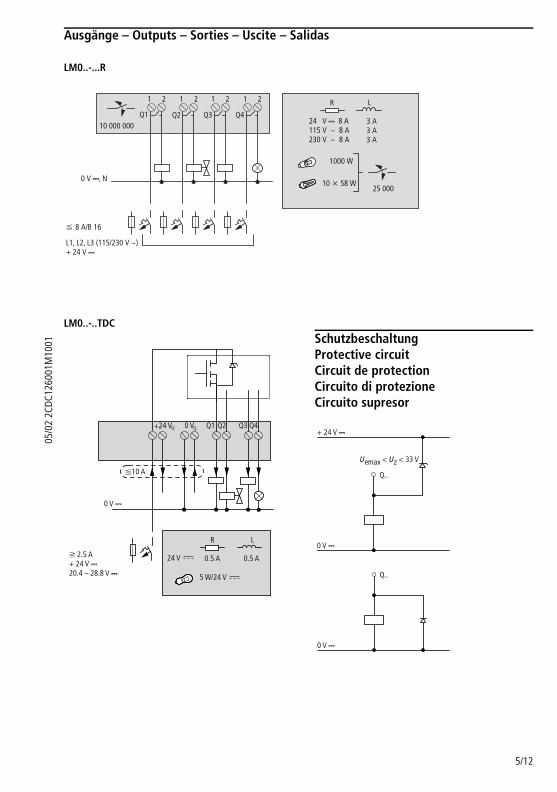
01Ausgänge – Outputs – Sorties – Uscite – Salidas
LM0..-...R
LM0..-..TDC
SchutzbeschaltungProtective circuitCircuit de protectionCircuito di protezioneCircuito supresor
0 V H, N
F 8 A/B 16
L1, L2, L3 (115/230 V h)+ 24 V H
25 000
R L
24 V H 8 A115 V h 8 A230 V h 8 A
3 A3 A3 A
1000 W
10 x 58 W
1 2 1 2 1 2 1 2
10 000 000Q1 Q2 Q3 Q4
0 V H
R L
24 V 0.5 A
+24 V 0 V Q1 Q2 Q3 Q4
F10 A
0.5 A
5 W/24 V
f 2.5 A+ 24 V H20.4 – 28.8 V H
Q Q
Uemax < Uz < 33 V
0 V H
Q..
+ 24 V H
0 V H
Q..
05/0
2 2C
DC12
6001
M10
01
16540502_BRANDLABEL.FM Seite 6 Montag, 15. Januar 2007 9:15 09
6/12
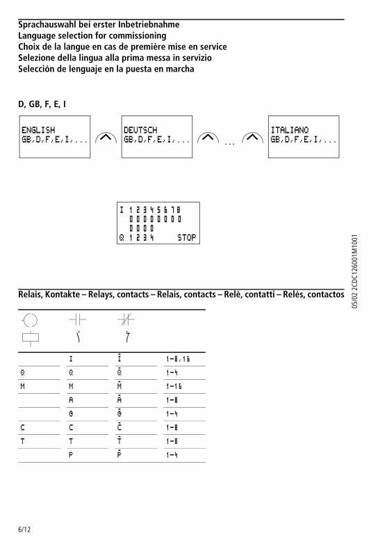
Sprachauswahl bei erster InbetriebnahmeLanguage selection for commissioningChoix de la langue en cas de première mise en serviceSelezione della lingua alla prima messa in servizioSelección de lenguaje en la puesta en marcha
D, GB, F, E, I
Relais, Kontakte – Relays, contacts – Relais, contacts – Relè, contatti – Relés, contactos
. . .
r R
I i 1-8,16
Q Q q 1-4
M M m 1-16
A a 1-8
Ö ö 1-4
C C c 1-8
T T t 1-8
P p 1-4
ENGLISHGB,D,F,E,I,...
DEUTSCHGB,D,F,E,I,...
ITALIANOGB,D,F,E,I,...
I 1 2 3 4 5 6 7 8 0 0 0 0 0 0 0 0 0 0 0 0Q 1 2 3 4 STOP
16540502_BRANDLABEL.FM Seite 7 Montag, 15. Januar 2007 9:15 09
7/12
05/0
2 2C
DC12
6001
M10
01
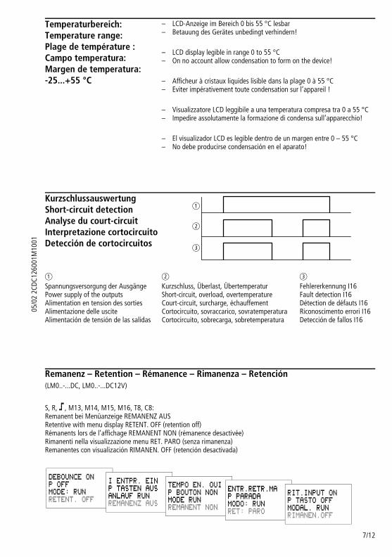
Remanenz – Retention – Rémanence – Rimanenza – Retención (LM0..-...DC, LM0..-...DC12V)
S, R, ä, M13, M14, M15, M16, T8, C8: Remanent bei Menüanzeige REMANENZ AUS Retentive with menu display RETENT. OFF (retention off) Rémanents lors de l’affichage REMANENT NON (rémanence desactivée) Rimanenti nella visualizzazione menu RET. PARO (senza rimanenza) Remanentes con visualización RIMANEN. OFF (retención desactivada)
Temperaturbereich:Temperature range:Plage de température :Campo temperatura:Margen de temperatura:-25...+55 °C
– –
LCD-Anzeige im Bereich 0 bis 55 °C lesbar Betauung des Gerätes unbedingt verhindern!
– –
LCD display legible in range 0 to 55 °C On no account allow condensation to form on the device!
– –
Afficheur à cristaux liquides lisible dans la plage 0 à 55 °C Eviter impérativement toute condensation sur l’appareil !
– –
Visualizzatore LCD leggibile a una temperatura compresa tra 0 a 55 °C Impedire assolutamente la formazione di condensa sull’apparecchio!
– –
El visualizador LCD es legible dentro de un margen entre 0 – 55 °C No debe producirse condensación en el aparato!
KurzschlussauswertungShort-circuit detectionAnalyse du court-circuitInterpretazione cortocircuitoDetección de cortocircuitos
a b c
Spannungsversorgung der Ausgänge Power supply of the outputs Alimentation en tension des sorties Alimentazione delle uscite Alimentación de tensión de las salidas
Kurzschluss, Überlast, Übertemperatur Short-circuit, overload, overtemperature Court-circuit, surcharge, échauffement Cortocircuito, sovraccarico, sovratemperatura Cortocircuito, sobrecarga, sobretemperatura
Fehlererkennung I16 Fault detection I16 Détection de défauts I16 Riconoscimento errori I16 Detección de fallos I16
a
b
c
DEBOUNCE ONP OFFMODE: RUNRETENT. OFF
I ENTPR. EINP TASTEN AUSANLAUF RUNREMANENZ AUS
TEMPO EN. OUIP BOUTON NONMODE RUNREMANENT NON
ENTR.RETR.MAP PARADAMODO: RUNRET: PARO
RIT.INPUT ONP TASTO OFFMODAL. RUNRIMANEN.OFF
05/0
2 2C
DC12
6001
M10
01
16540502_BRANDLABEL.FM Seite 8 Montag, 15. Januar 2007 9:15 09
8/12
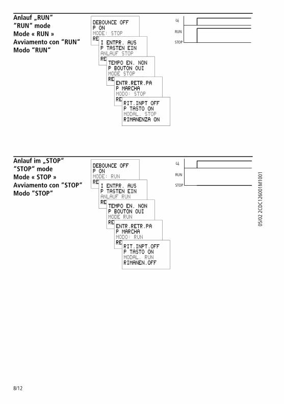
Anlauf „RUN““RUN“ modeMode « RUN »Avviamento con “RUN“Modo “RUN“
Anlauf im „STOP““STOP“ modeMode « STOP »Avviamento con “STOP“Modo “STOP“
DEBOUNCE OFFP ONMODE: STOPRETENTION ON
I ENTPR. AUSP TASTEN EINANLAUF STOPREMANENZ EIN
TEMPO EN. NONP BOUTON OUIMODE STOPREMANENT OUI
ENTR.RETR.PAP MARCHAMODO: STOPRET: MARCHA
RIT.INPT OFFP TASTO ONMODAL. STOPRIMANENZA ON
STOP
RUN
Ue
DEBOUNCE OFFP ONMODE: RUNRETENT. OFF
I ENTPR. AUSP TASTEN EINANLAUF RUNREMANENZ AUS
TEMPO EN. NONP BOUTON OUIMODE RUNREMANENT NON
ENTR.RETR.PAP MARCHAMODO: RUNRET: PARO
RIT.INPT.OFFP TASTO ONMODAL. RUNRIMANEN.OFF
STOP
RUN
Ue
16540502_BRANDLABEL.FM Seite 9 Montag, 15. Januar 2007 9:15 09
9/12
05/0
2 2C
DC12
6001
M10
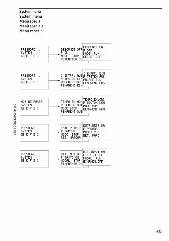
01SystemmenüSystem menuMenu spécialMenù specialeMenú especial
DEBOUNCE OFFP ONMODE: STOPRETENTION ON
PASSWORD...SYSTEMGB D F E I
DEBOUNCE ONP OFFMODE: RUNRETENT.OFF
PASSWORT...SYSTEMGB D F E I
I ENTPR. AUSP TASTEN EINANLAUF STOPREMANENZ EIN
I ENTPR. EINP TASTEN AUSANLAUF RUNREMANENZ AUS
MOT DE PASSESYSTEMGB D F E I
TEMPO EN.NONP BOUTON OUIMODE STOPREMANENT OUI
TEMPO EN.OUIP BOUTON NONMODE RUNREMANENT NON
PASSWORD...SYSTEMGB D F E I
ENTR.RETR.PAP MARCHAMODO: STOPRET. MARCHA
ENTR.RETR.MAP PARADAMODO: RUNRET. PARO
PASSWORD...SYSTEMGB D F E I
RIT.INPT.OFFP TASTO ONMODAL. STOPRIMANENZA ON
RIT.INPUT ONP TASTO OFFMODAL. RUNRIMANEN.OFF
05/0
2 2C
DC12
6001
M10
01
16540502_BRANDLABEL.FM Seite 10 Montag, 15. Januar 2007 9:15 09
10/12
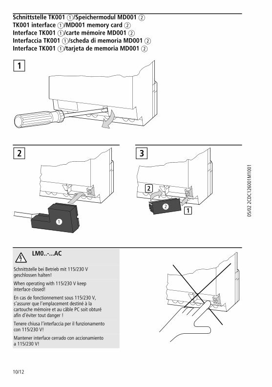
Schnittstelle TK001 a/Speichermodul MD001 b TK001 interface a/MD001 memory card b Interface TK001 a/carte mémoire MD001 b Interfaccia TK001 a/scheda di memoria MD001 b Interface TK001 a/tarjeta de memoria MD001 b
LM0..-...AC
Schnittstelle bei Betrieb mit 115/230 V geschlossen halten!
When operating with 115/230 V keep interface closed!
En cas de fonctionnement sous 115/230 V, s’assurer que l’emplacement destiné à la cartouche mémoire et au câble PC soit obturé afin d’éviter tout danger !
Tenere chiusa l’interfaccia per il funzionamento con 115/230 V!
Mantener interface cerrado con accionamiento a 115/230 V!
1
2
2
1
3
16540502_BRANDLABEL.FM Seite 11 Montag, 15. Januar 2007 9:15 09
11/12
05/0
2 2C
DC12
6001
M10
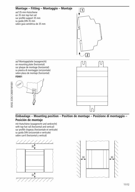
01Montage – Fitting – Montaggio – Montajeauf 35-mm-Hutschiene on 35 mm top-hat rail sur profilé-support 35 mm su guida DIN 35 mm sobre guía semétrica de 35 mm
auf Montageplatte (waagerecht) on mounting plate (horizontal) sur plaque de montage (horizontal) su piastra di montaggio (orizzontale) sobre placa de montaje (horizontal)FD001
Einbaulage – Mounting position – Position de montage – Posizione di montaggio – Posición de montajemit Hutschiene (waagerecht und senkrecht) with top-hat rail (horizontal and vertical) sur profilé chapeau (horizontale et verticale) su guida DIN (orizzontale e verticale) sobre carril (horizontal y vertical)
1
2
CLICK !
3030
3030
05/0
2 2C
DC12
6001
M10
01
16540502_BRANDLABEL.FM Seite 12 Montag, 15. Januar 2007 9:15 09
12/12
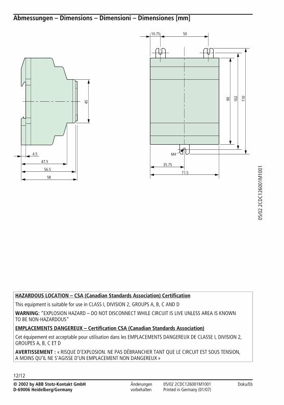
Abmessungen – Dimensions – Dimensioni – Dimensiones [mm]
HAZARDOUS LOCATION – CSA (Canadian Standards Association) Certification
This equipment is suitable for use in CLASS I, DIVISION 2, GROUPS A, B, C AND D
WARNING: “EXPLOSION HAZARD – DO NOT DISCONNECT WHILE CIRCUIT IS LIVE UNLESS AREA IS KNOWN TO BE NON-HAZARDOUS“
EMPLACEMENTS DANGEREUX – Certification CSA (Canadian Standards Association)
Cet équipement est acceptable pour utilisation dans les EMPLACEMENTS DANGEREUX DE CLASSE I, DIVISION 2, GROUPES A, B, C ET D
AVERTISSEMENT : « RISQUE D’EXPLOSION. NE PAS DÉBRANCHER TANT QUE LE CIRCUIT EST SOUS TENSION, A MOINS QU’IL NE S’AGISSE D’UN EMPLACEMENT NON DANGEREUX »
47.5
56.5
58
45
4.5
10.75 50
M4
35.75
71.5
90 102
110
© 2002 by ABB Stotz-Kontakt GmbH D-69006 Heidelberg/Germany
Änderungen vorbehalten
05/02 2CDC126001M1001 Doku/Eb Printed in Germany (01/07)