Embed Size (px)
Citation preview
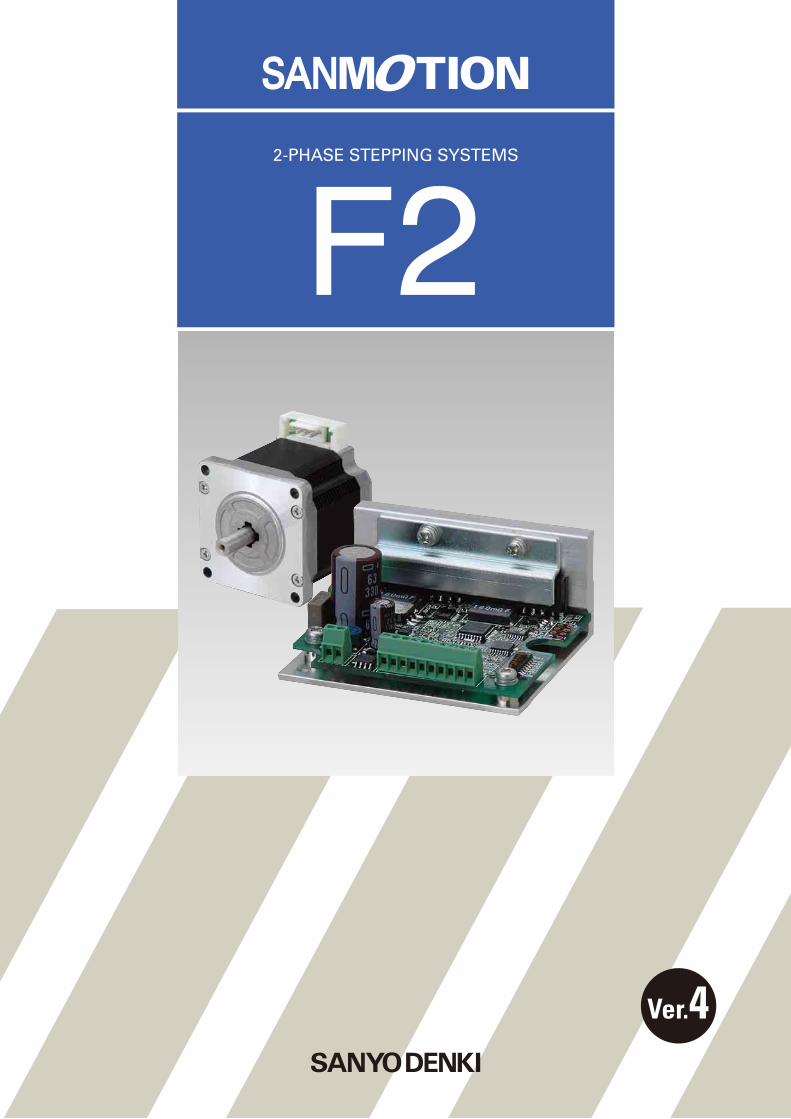
2-PHASE STEPPING SYSTEMS
Ver.4
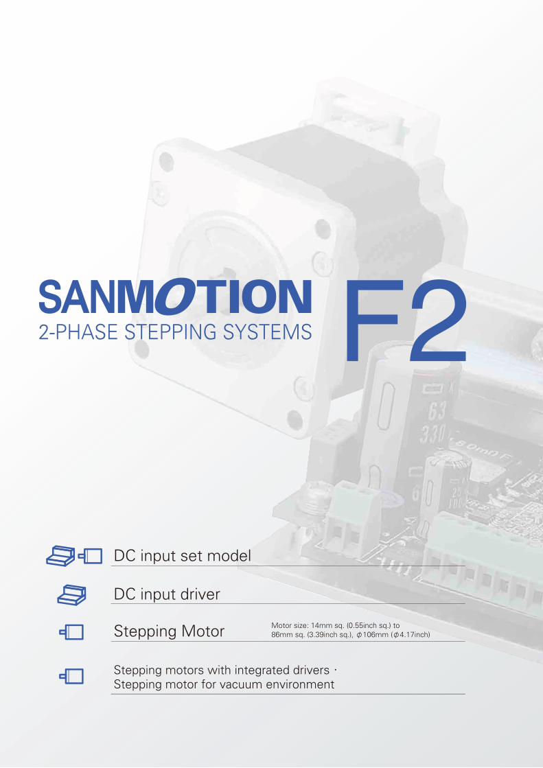
DC input set model
DC input driver
Stepping Motor
Stepping motors with integrated drivers・Stepping motor for vacuum environment
Motor size: 14mm sq. (0.55inch sq.) to 86mm sq. (3.39inch sq.), φ106mm (φ4.17inch)
Features ・・・・・・・・・・・・・・・・・・・・・・・・・・・・・・・P.4
Line up・・・・・・・・・・・・・・・・・・・・・・・・・・・・・・・・・P.5
Lineup Details ・・・・・・・・・・・・・・・・・・・・・・・・・・P.6
DC input set model ・・・・・・・・・・・・・・・・・・・・・P.8System confi guration diagram ・・・・・・・・・・・・・・・P.8Set model numbering convention ・・・・・・・・・・・・P.9Set Model Confi guration ・・・・・・・・・・・・・・・・・・・・・P.10
Unipolar models specifi cations ・・・・・・・・・・・・・・・P.11
Bipolar models specifi cations ・・・・・・・・・・・・・・・・P.14
Driver specifi cations ・・・・・・・・・・・・・・・・・・・・・・・・・P.19
Driver Controls and Connectors ・・・・・・・・・・・・・・P.20
Connections and Signals ・・・・・・・・・・・・・・・・・・・・・P.21
Stepping Motor ・・・・・・・・・・・・・・・・・・・・・・・・P.24
Stepping motors with integrated drivers ・・P.55
Stepping motor for vacuum environment ・・P.63
Dimensions ・・・・・・・・・・・・・・・・・・・・・・・・・・・・P.64
Safety Consideration ・・・・・・・・・・・・・・・・・・・P.71
Contents
4
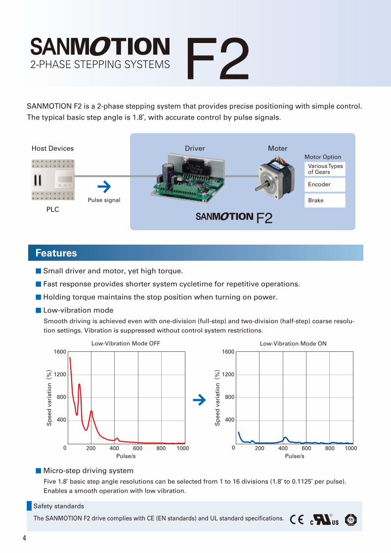
SANMOTION F2 is a 2-phase stepping system that provides precise positioning with simple control.
The typical basic step angle is 1.8°, with accurate control by pulse signals.
Host Devices
PLC
Driver Moter
Motor Option
Various Types of Gears
Encoder
BrakePulse signal
Features
■ Low-vibration mode
■ Small driver and motor, yet high torque.
■ Fast response provides shorter system cycletime for repetitive operations.
■ Holding torque maintains the stop position when turning on power.
Safety standards
The SANMOTION F2 drive complies with CE (EN standards) and UL standard specifications.
Smooth driving is achieved even with one-division (full-step) and two-division (half-step) coarse resolu-
tion settings. Vibration is suppressed without control system restrictions.
■ Micro-step driving system
Five 1.8° basic step angle resolutions can be selected from 1 to 16 divisions (1.8° to 0.1125° per pulse).
Enables a smooth operation with low vibration.
400
800
1200
1600
0 200 400 600 800 1000
Low-Vibration Mode ON
400
800
1200
1600
0 200 400 600 800 1000
Pulse/s
Sp
ee
d v
ari
ati
on(
%)
Sp
ee
d v
ari
ati
on(
%)
Pulse/s
Low-Vibration Mode OFF
5
Line up
Bipolar
These set models consist of a DC-powered driver and motor.
The motor winding specifi cation is bipolar.
Motor size:
28mm sq. (1.10inch sq.) / 42mm sq.(1.65inch sq.) / 50mm sq (1.97inch sq.) /
56mm sq. (2.20inch sq.) / 60mm sq. (2.36inch sq.)
This is a high-torque stepping motor. Select from a broad
lineup of products with ultra-compact 14 mm sq. (0.55
in sq.) motor size, or a thin 11.4 mm (0.45 in) motor - the
shortest motor length.
A separate driver is required.
Motor size:
14mm sq. (0.55inch sq.) / 28mm sq. (1.10inch sq.) /
35mm sq. (1.38inch sq.) / 42mm sq. (1.65inch sq.) /
50mm sq. (1.97inch sq.) / 56mm sq. (2.20inch sq.) /
60mm sq. (2.36inch sq.) / 86mm sq.
(3.39inch sq., CE and UL models are available.) / φ106mm (φ4.17inch)
These include integrated drivers. They reduce mounting
space requirements and wiring complexity.
Operating modes are selectable from pulse train control,
and control by general-purpose I/O (parallel interface) or
by RS-485 compliant serial communications.
Motor size:
42mm sq. (1.65inch sq.) /
60mm sq. (2.36inch sq.)
"We customize motors for use in low to ultra-high vacuum
environments to suit your system requirements.
A separate driver is required.
DC input
Unipolar
These set models consist of a DC-powered driver and motor.
The motor winding specifi cation is unipolar.
Motor size:
28mm sq. (1.10inch sq.) / 42mm sq. (1.65inch sq.) / 56mm sq.(2.20inch sq.)
Convenient set models consist of a DC-powered driver and motor.
Beside the set models, only stepping motors can be selected.
The lineup also includes stepping motors with built-in drivers, and stepping motors for vacuum environments.
Set model
Stepping Motor Stepping motors with integrated drivers
Stepping motor for vacuum environment Customized Products
5
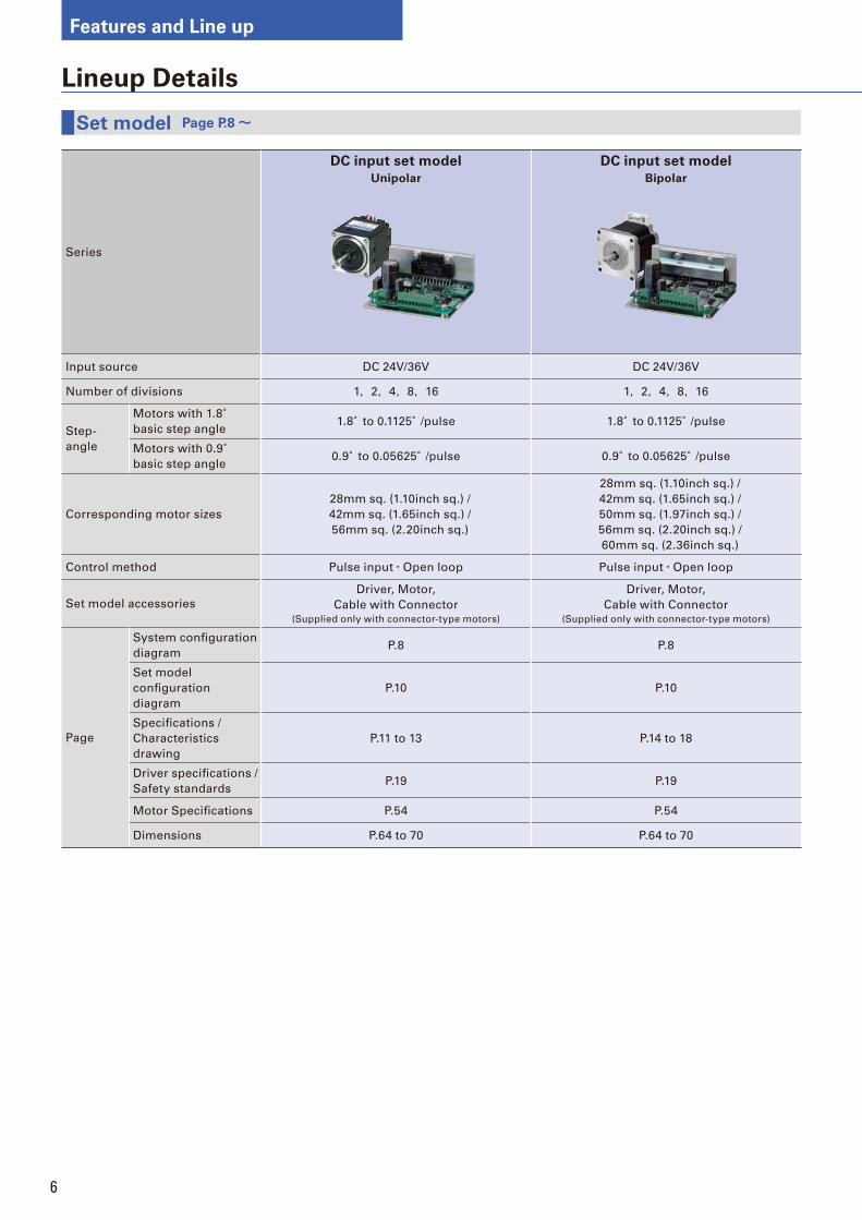
6
Series
DC input set model
Unipolar
DC input set model
Bipolar
Input source DC 24V/36V DC 24V/36V
Number of divisions 1,2,4,8,16 1,2,4,8,16
Step-
angle
Motors with 1.8° basic step angle
1.8° to 0.1125°/pulse 1.8° to 0.1125°/pulse
Motors with 0.9° basic step angle
0.9° to 0.05625°/pulse 0.9° to 0.05625°/pulse
Corresponding motor sizes
28mm sq. (1.10inch sq.) /
42mm sq. (1.65inch sq.) /
56mm sq. (2.20inch sq.)
28mm sq. (1.10inch sq.) /
42mm sq. (1.65inch sq.) /
50mm sq. (1.97inch sq.) /
56mm sq. (2.20inch sq.) /
60mm sq. (2.36inch sq.)
Control method Pulse input・Open loop Pulse input・Open loop
Set model accessories
Driver, Motor,
Cable with Connector(Supplied only with connector-type motors)
Driver, Motor,
Cable with Connector(Supplied only with connector-type motors)
Page
System confi guration
diagramP.8 P.8
Set model
confi guration
diagram
P.10 P.10
Specifi cations /
Characteristics
drawing
P.11 to 13 P.14 to 18
Driver specifi cations /
Safety standardsP.19 P.19
Motor Specifi cations P.54 P.54
Dimensions P.64 to 70 P.64 to 70
Set model Page P.8~
Lineup Details
Features and Line up
7
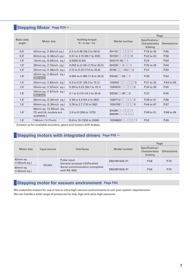
Basic step
angleMotor size
Holding torque
N・m (oz・in)Model number
Page
Specifi cations /
Characteristics
drawing
Dimensions
0.9° 42mm sq. (1.65inch sq.) 0.2 to 0.48 (28.3 to 68.0) SH142□ -□□□ 1 P.29 to 30 P.65
0.9° 60mm sq. (2.36inch sq.) 0.57 to 2.15 (80.7 to 304) SH160□ -□□□ 0 P.42 to 43 P.66
1.8° 14mm sq. (0.55inch sq.) 0.0065 (0.92) SH2141-55□ 1 P.24 P.64
1.8° 28mm sq. (1.10inch sq.) 0.055 to 0.145 (7.79 to 20.5) SH228□ -5□□ 1 P.25 to 26 P.64
1.8° 35mm sq. (1.38inch sq.) 0.12 to 0.23 (17.0 to 32.6) SH35□□ -12U□ 0 P.27 P.64
1.8°42mm sq. (1.65inch sq.)
Slim form0.083 to 0.186 (11.8 to 26.3) SS242□ -50□ 1 P.28 P.64
1.8° 42mm sq. (1.65inch sq.) 0.2 to 0.51 (28.3 to 72.2) 103H52□□ -□□□ 0 P.31 to 33 P.64 to 65
1.8° 50mm sq. (1.97inch sq.) 0.28 to 0.53 (39.7 to 75.1) 103H670□ -□□□ 0 P.34 to 36 P.65
1.8°50mm sq. (1.97inch sq.)
Slim form0.1 to 0.215 (14.2 to 30.4) SS250□ -80□ 0 P.37 P.65
1.8° 56mm sq. (2.20inch sq.) 0.39 to 2.0 (55.2 to 283) 103H712□ -□□□ 0 P.38 to 41 P.66
1.8° 60mm sq. (2.36inch sq.) 0.78 to 2.7 (110 to 382) 103H782□ -□□□ 0 P.44 to 47 P.67
1.8°86mm sq. (3.39inch sq.,
CE and UL models are
available.)2.5 to 9 (358 to 1270)
SH286□ -□□□ 1
SM286□ -□□□□ P.48 to 51 P.68 to 69
1.8° φ106mm (φ4.17inch) 10.8 to 19 (1530 to 2690) 103H8922□ -□□□ 1 P.52 P.69
・ Contact us for available encoders, gears and motors with brakes.
Motor size Input source Interfaces Model number
Page
Specifi cations /
Characteristics
drawing
Dimensions
42mm sq.
(1.65inch sq.)DC24V
・ Pulse input
・ General-purpose I/O(Parallel)
・ Serial communication (compliant
with RS-485)
DB21M142S-01 P.56 P.70
60mm sq.
(1.65inch sq.)DB22M162S-01 P.56 P.70
We customize motors for use in low to ultra-high vacuum environments to suit your system requirements.
We can handle a wide range of pressures for low, high and ultra-high vacuums.
Stepping Motor Page P.24~
Stepping motors with integrated drivers Page P.55~
Stepping motor for vacuum environment Page P.63
7
8
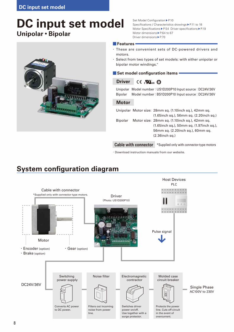
DC input set model
System confi guration diagram
DC input set modelUnipolar・Bipolar
Set Model Confi guration P.10 Specifi cations / Characteristics drowings P.11 to 18Motor Specifi cations P.54 Driver specifi cations P.19Motor dimensions P.64 to 67 Driver dimensions P.70
■Features
・ These are convenient sets of DC-powered drivers and
motors.
・ Select from two types of set models: with either unipolar or
bipolar motor windings."
■Set model confi guration items
Driver
Unipolar Model number:US1D200P10 Input source:DC24V/36V
Bipolar Model number:BS1D200P10 Input source:DC24V/36V
Motor
Unipolar Motor size: 28mm sq. (1.10inch sq.), 42mm sq.
(1.65inch sq.), 56mm sq. (2.20inch sq.)
Bipolar Motor size: 28mm sq. (1.10inch sq.), 42mm sq.
(1.65inch sq.), 50mm sq. (1.97inch sq.),
56mm sq. (2.20inch sq.), 60mm sq.
(2.36inch sq.)
Cable with connector *Supplied only with connector-type motors
・ Download instruction manuals from our website.
Host Devices
Driver(Photo: US1D200P10)
Motor
Cable with connector*Supplied only with connector-type motors.
PLC
Pulse signal
Single PhaseAC100V to 230V
DC24V/36V
・Encoder (option)
・Brake (option)
・Gear (option)
Noise filterSwitching power supply
Electromagnetic contractor
Molded casecircuit breaker
Protects the power
line. Cuts off circuit
in the event of
overcurrent.
Switches driver
power on/off.
Use together with a
surge protector.
Filters out incoming
noise from power
line.
Converts AC power
to DC power.
9
DC
in
pu
t se
t m
od
el
Ste
pp
ing
Mo
tor
Ste
pp
ing
mo
tors
wit
h
inte
gra
ted
dri
ve
rsS
tep
pin
g m
oto
r fo
r v
acu
um
en
vir
on
me
nt
Dim
en
sio
ns
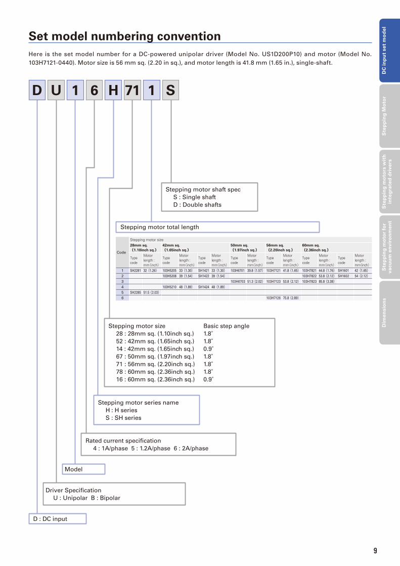
Set model numbering convention
D H 7161 1 SU
Stepping motor shaft spec
S : Single shaft
D : Double shafts
D : DC input
Driver Specifi cation
U : Unipolar B : Bipolar
Model
Rated current specifi cation
4 : 1A/phase 5 : 1.2A/phase 6 : 2A/phase
Stepping motor total length
Stepping motor series name
H : H series
S : SH series
Stepping motor size Basic step angle
28 : 28mm sq. (1.10inch sq.) 1.8° 52 : 42mm sq. (1.65inch sq.) 1.8° 14 : 42mm sq. (1.65inch sq.) 0.9° 67 : 50mm sq. (1.97inch sq.) 1.8° 71 : 56mm sq. (2.20inch sq.) 1.8° 78 : 60mm sq. (2.36inch sq.) 1.8° 16 : 60mm sq. (2.36inch sq.) 0.9°
Here is the set model number for a DC-powered unipolar driver (Model No. US1D200P10) and motor (Model No.
103H7121-0440). Motor size is 56 mm sq. (2.20 in sq.), and motor length is 41.8 mm (1.65 in.), single-shaft.
Code
Stepping motor size28mm sq.
(1.10inch sq.)42mm sq.
(1.65inch sq.)50mm sq.
(1.97inch sq.)56mm sq.
(2.20inch sq.)60mm sq.
(2.36inch sq.)
Type code
Motor length : mm(inch)
Type code
Motor length : mm(inch)
Type code
Motor length : mm(inch)
Type code
Motor length : mm(inch)
Type code
Motor length : mm(inch)
Type code
Motor length : mm(inch)
Type code
Motor length : mm(inch)
1 SH2281 32(1.26) 103H5205 33(1.30) SH1421 33(1.30) 103H6701 39.8(1.57) 103H7121 41.8(1.65) 103H7821 44.8(1.76) SH1601 42(1.65)2 103H5208 39(1.54) SH1422 39(1.54) 103H7822 53.8(2.12) SH1602 54(2.12)3 103H6703 51.3(2.02) 103H7123 53.8(2.12) 103H7823 85.8(3.38)4 103H5210 48(1.89) SH1424 48(1.89)5 SH2285 51.5(2.03)6 103H7126 75.8(2.89)
9

10
DC input set model
Set Model Confi guration This is a set comprising a driver, motor and cable with motor connector.
Unipolar Bundled driver model number:US1D200P10
Motor size
Single shaft Double shaftsBasic
step
angle
Rated
current
(A/phase)
Page
Set model
number
Set confi guration itemsSet model
number
Set confi guration itemsMotor model number
Cable with motor connector model number
Motor model number
Cable with motor connector model number
Specifi -cations
Dimen-sions
28mm
sq.
DU14S281S SH2281-5271 - DU14S281D SH2281-5231 - 1.8° 1 P.11 P.64
DU14S285S SH2285-5271 - DU14S285D SH2285-5231 - 1.8° 1 P.11 P.64
42mm
sq.
DU15H521S 103H5205-0440 4835710-1 DU15H521D 103H5205-0410 4835710-1 1.8° 1.2 P.11 P.64
DU15H522S 103H5208-0440 4835710-1 DU15H522D 103H5208-0410 4835710-1 1.8° 1.2 P.11 P.64
DU15H524S 103H5210-0440 4835710-1 DU15H524D 103H5210-0410 4835710-1 1.8° 1.2 P.12 P.64
DU15S141S SH1421-0441 - DU15S141D SH1421-0411 - 0.9° 1.2 P.12 P.65
DU15S142S SH1422-0441 - DU15S142D SH1422-0411 - 0.9° 1.2 P.12 P.65
DU15S144S SH1424-0441 - DU15S144D SH1424-0411 - 0.9° 1.2 P.12 P.65
56mm
sq.
DU16H711S 103H7121-0440 - DU16H711D 103H7121-0410 - 1.8° 2 P.13 P.66
DU16H713S 103H7123-0440 - DU16H713D 103H7123-0410 - 1.8° 2 P.13 P.66
DU16H716S 103H7126-0440 - DU16H716D 103H7126-0410 - 1.8° 2 P.13 P.66
● Cable with motor connector *Supplied only with connector-type motors
Bundled cable(Unipolar 42mm sq. (1.65inch sq.) motors only, model number: 4835710-1)
500 (1.64 feet) MIN.
Pin No.Black
Red
Yellow
Blue
Orange
White
6
5
4
3
2
1
Lead wire color
Maker: J.S.T Mfg.Co.,Ltd
Lead wire: UL1430 AWG26
Housing: EHR-6 Black
Pin: SEH-001T-P0.6
Bipolar Bundled driver model number:BS1D200P10
Motor size
Single shaft Double shaftsBasic
step
angle
Rated
current
(A/phase)
Page
Set model
number
Set confi guration itemsSet model number
Set confi guration itemsMotor model number
Cable with motor connector model number
Motor model number
Cable with motor connector model number
Specifi -cations
Dimen-sions
28mm
sq.
DB14S281S SH2281-5771 - DB14S281D SH2281-5731 - 1.8° 1 P.14 P.64
DB14S285S SH2285-5771 - DB14S285D SH2285-5731 - 1.8° 1 P.14 P.64
42mm
sq.
DB14H521S 103H5205-5240 - DB14H521D 103H5205-5210 - 1.8° 1 P.14 P.65
DB14H522S 103H5208-5240 - DB14H522D 103H5208-5210 - 1.8° 1 P.14 P.65
DB14H524S 103H5210-5240 - DB14H524D 103H5210-5210 - 1.8° 1 P.15 P.65
DB16S141S SH1421-5241 - DB16S141D SH1421-5211 - 0.9° 2 P.15 P.65
DB16S142S SH1422-5241 - DB16S142D SH1422-5211 - 0.9° 2 P.15 P.65
DB16S144S SH1424-5241 - DB16S144D SH1424-5211 - 0.9° 2 P.15 P.65
50mm
sq.
DB16H671S 103H6701-5040 - DB16H671D 103H6701-5010 - 1.8° 2 P.16 P.65
DB16H673S 103H6703-5040 - DB16H673D 103H6703-5010 - 1.8° 2 P.16 P.65
56mm
sq.
DB16H711S 103H7121-5740 - DB16H711D 103H7121-5710 - 1.8° 2 P.16 P.66
DB16H713S 103H7123-5740 - DB16H713D 103H7123-5710 - 1.8° 2 P.16 P.66
DB16H716S 103H7126-5740 - DB16H716D 103H7126-5710 - 1.8° 2 P.17 P.66
60mm
sq.
DB16H781S 103H7821-5740 4837961-1 DB16H781D 103H7821-5710 4837961-1 1.8° 2 P.17 P.67
DB16H782S 103H7822-5740 4837961-1 DB16H782D 103H7822-5710 4837961-1 1.8° 2 P.17 P.67
DB16H783S 103H7823-5740 4837961-1 DB16H783D 103H7823-5710 4837961-1 1.8° 2 P.17 P.67
DB16S161S SH1601-5240 - DB16S161D SH1601-5210 - 0.9° 2 P.18 P.66
DB16S162S SH1602-5240 - DB16S162D SH1602-5210 - 0.9° 2 P.18 P.66
● Cable with motor connector *Supplied only with connector-type motors
Bundled cable (Bipolar 60 mm sq. (2.36inch sq.) motors only, model number: 4837961-1)
4
3
2
1
Pin No.Yellow
Red
Blue
Orange
Lead wire color
Maker: J.S.T Mfg.Co.,Ltd
Housing: VHR-4N
Pin: SVH-21T-P1.1
500 (1.64 feet) MIN.
Lead wire: UL1430 AWG22
11
DC
in
pu
t se
t m
od
el
Ste
pp
ing
Mo
tor
Ste
pp
ing
mo
tors
wit
h
inte
gra
ted
dri
ve
rsS
tep
pin
g m
oto
r fo
r v
acu
um
en
vir
on
me
nt
Dim
en
sio
ns
Pulse rate (kpulse/s)
Number of rotations (min-1)
Torq
ue (
N・
m)
Sour
ce c
urre
nt (A)
0
0.02
0.04
0.06
0.08
0.1
0.1 1 10 100012345678910
Full stepHalf step
2000 3000 5000100 10002000 3000 5000100 1000
Pull-out torque
Source current
0
Torq
ue (
oz・
in.)
14
12
10
8
6
4
2
0
0.02
0.04
0.06
0.08
0.1
0.1 1 10 100012345678910
Full stepHalf step
2000 3000 5000100 10002000 3000 5000100 1000
Pull-out torque
Source current
Pulse rate (kpulse/s)
Number of rotations (min-1)To
rque
(N・
m)
Sour
ce c
urre
nt (A)
0
Torq
ue (
oz・
in.)
14
12
10
8
6
4
2
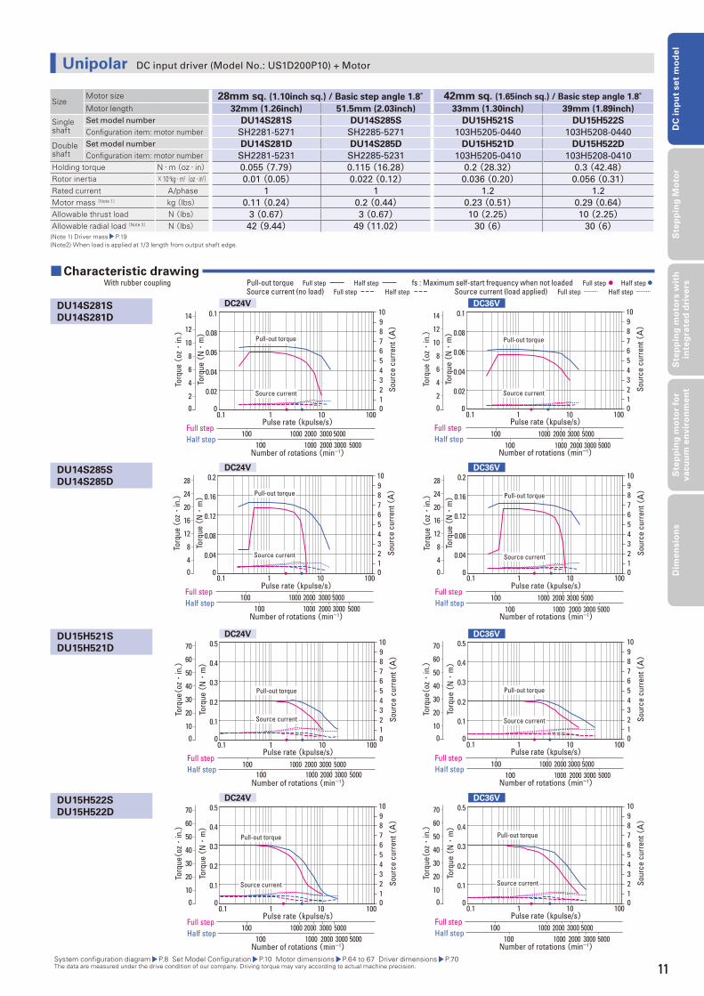
SizeMotor size 28mm sq. (1.10inch sq.) / Basic step angle 1.8° 42mm sq. (1.65inch sq.) / Basic step angle 1.8°Motor length 32mm (1.26inch) 51.5mm (2.03inch) 33mm (1.30inch) 39mm (1.89inch)
Single shaft
Set model number DU14S281S DU14S285S DU15H521S DU15H522S
Confi guration item: motor number SH2281-5271 SH2285-5271 103H5205-0440 103H5208-0440
Double shaft
Set model number DU14S281D DU14S285D DU15H521D DU15H522D
Confi guration item: motor number SH2281-5231 SH2285-5231 103H5205-0410 103H5208-0410
Holding torque N・m(oz・in) 0.055 (7.79) 0.115 (16.28) 0.2 (28.32) 0.3 (42.48)Rotor inertia × 10-4kg・m2(oz・in2) 0.01 (0.05) 0.022 (0.12) 0.036 (0.20) 0.056 (0.31)Rated current A/phase 1 1 1.2 1.2
Motor mass (Note 1) kg(lbs) 0.11 (0.24) 0.2 (0.44) 0.23 (0.51) 0.29 (0.64)Allowable thrust load N (lbs) 3 (0.67) 3 (0.67) 10 (2.25) 10 (2.25)Allowable radial load (Note 2) N (lbs) 42 (9.44) 49 (11.02) 30 (6) 30 (6)(Note 1) Driver mass P.19(Note2) When load is applied at 1/3 length from output shaft edge.
System confi guration diagram P.8 Set Model Confi guration P.10 Motor dimensions P.64 to 67 Driver dimensions P.70 The data are measured under the drive condition of our company. Driving torque may vary according to actual machine precision.
■ Characteristic drawing With rubber coupling fs : Maximum self-start frequency when not loaded Full step Half step Pull-out torque Full step Half step
Source current (load applied) Full step Half step Source current (no load) Full step Half step
DU14S281S
DU14S281D
DU14S285S
DU14S285D
DU15H521S
DU15H521D
DU15H522S
DU15H522D
DC24V
DC24V
DC24V
DC24V
DC36V
DC36V
DC36V
DC36V
Pulse rate (kpulse/s)
Number of rotations (min-1)
Torq
ue (
N・
m)
Sour
ce c
urre
nt (A)
0
0.04
0.08
0.12
0.16
0.2
0.1 1 10 100012345678910
Full stepHalf step
2000 3000 5000100 10002000 3000 5000100 1000
Pull-out torque
Source current
0
Torq
ue (
oz・
in.)
28
20
16
24
12
8
4
Pulse rate (kpulse/s)
Number of rotations (min-1)
Torq
ue (
N・
m)
Sour
ce c
urre
nt (A)
0
0.04
0.08
0.12
0.16
0.2
0.1 1 10 100012345678910
Full stepHalf step
2000 3000 5000100 10002000 3000 5000100 1000
Pull-out torque
Source current
0
Torq
ue (
oz・
in.)
28
20
16
24
12
8
4
Pulse rate (kpulse/s)
Number of rotations (min-1)
Torq
ue (
N・
m)
Sour
ce c
urre
nt (A)
0
0.1
0.2
0.3
0.4
0.5
0.1 1 10 100012345678910
Full stepHalf step
2000 3000 5000100 10002000 3000 5000100 1000
Pull-out torque
Source current
0
Torq
ue(oz・
in.)
70
60
50
40
30
20
10
Pulse rate (kpulse/s)
Number of rotations (min-1)
Torq
ue (
N・
m)
Sour
ce c
urre
nt (A)
0
0.1
0.2
0.3
0.4
0.5
0.1 1 10 100012345678910
Full stepHalf step
2000 3000 5000100 10002000 3000 5000100 1000
Pull-out torque
Source current
0
Torq
ue(oz・
in.)
70
60
50
40
30
20
10
Pulse rate (kpulse/s)
Number of rotations (min-1)
Torq
ue (
N・
m)
Sour
ce c
urre
nt (A)
0
0.1
0.2
0.3
0.4
0.5
0.1 1 10 100012345678910
Full stepHalf step
2000 3000 5000100 10002000 3000 5000100 1000
Pull-out torque
Source current
0
Torq
ue(oz・
in.)
70
60
50
40
30
20
10
Pulse rate (kpulse/s)
Number of rotations (min-1)
Torq
ue (
N・
m)
Sour
ce c
urre
nt (A)
0
0.1
0.2
0.3
0.4
0.5
0.1 1 10 100012345678910
Full stepHalf step
2000 3000 5000100 10002000 3000 5000100 1000
Pull-out torque
Source current
0
Torq
ue(oz・
in.)
70
60
50
40
30
20
10
Unipolar DC input driver (Model No.: US1D200P10) + Motor
11
12
DC input set model
Pulse rate (kpulse/s)
Number of rotations (min-1)
Torq
ue (
N・
m)
Sour
ce c
urre
nt (A)
0
0.1
0.2
0.3
0.4
0.5
0.1 1 10 100012345678910
Full stepHalf step
2000 3000 5000100 10002000 3000 5000100 1000
Pull-out torque
Source current
0
Torq
ue(oz・
in.)
70
60
50
40
30
20
10
Pulse rate (kpulse/s)
Number of rotations (min-1)To
rque
(N・
m)
Sour
ce c
urre
nt (A)
0
0.1
0.2
0.3
0.4
0.5
0.1 1 10 100012345678910
Full stepHalf step
2000 3000 5000100 10002000 3000 5000100 1000
Pull-out torque
Source current
0
Torq
ue(oz・
in.)
70
60
50
40
30
20
10
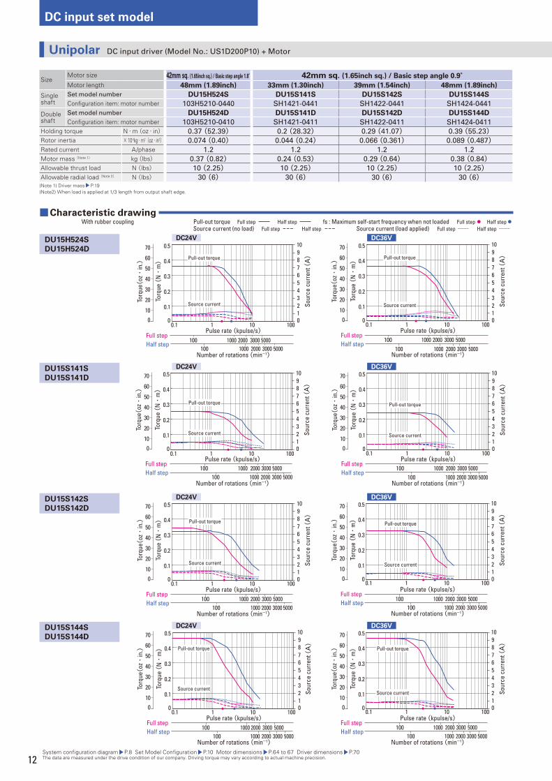
SizeMotor size 42mm sq. (1.65inch sq.) / Basic step angle 1.8° 42mm sq. (1.65inch sq.) / Basic step angle 0.9°Motor length 48mm (1.89inch) 33mm (1.30inch) 39mm (1.54inch) 48mm (1.89inch)
Single shaft
Set model number DU15H524S DU15S141S DU15S142S DU15S144S
Confi guration item: motor number 103H5210-0440 SH1421-0441 SH1422-0441 SH1424-0441
Double shaft
Set model number DU15H524D DU15S141D DU15S142D DU15S144D
Confi guration item: motor number 103H5210-0410 SH1421-0411 SH1422-0411 SH1424-0411
Holding torque N・m(oz・in) 0.37 (52.39) 0.2 (28.32) 0.29 (41.07) 0.39 (55.23)Rotor inertia × 10-4kg・m2(oz・in2) 0.074 (0.40) 0.044 (0.24) 0.066 (0.361) 0.089 (0.487)Rated current A/phase 1.2 1.2 1.2 1.2
Motor mass (Note 1) kg(lbs) 0.37 (0.82) 0.24 (0.53) 0.29 (0.64) 0.38 (0.84)Allowable thrust load N (lbs) 10 (2.25) 10 (2.25) 10 (2.25) 10 (2.25)Allowable radial load (Note 2) N (lbs) 30 (6) 30 (6) 30 (6) 30 (6)(Note 1) Driver mass P.19(Note2) When load is applied at 1/3 length from output shaft edge.
System confi guration diagram P.8 Set Model Confi guration P.10 Motor dimensions P.64 to 67 Driver dimensions P.70 The data are measured under the drive condition of our company. Driving torque may vary according to actual machine precision.
■ Characteristic drawing With rubber coupling fs : Maximum self-start frequency when not loaded Full step Half step Pull-out torque Full step Half step
Source current (load applied) Full step Half step Source current (no load) Full step Half step
DU15H524S
DU15H524D
DU15S141S
DU15S141D
DU15S142S
DU15S142D
DU15S144S
DU15S144D
DC24V
DC24V
DC24V
DC24V
DC36V
DC36V
DC36V
DC36V
Pulse rate (kpulse/s)
Number of rotations (min-1)
Torq
ue (
N・
m)
Sour
ce c
urre
nt (A)
0
0.1
0.2
0.3
0.4
0.5
0.1 1 10 100012345678910
Full stepHalf step
2000 3000 5000100 10002000 3000 5000100 1000
Pull-out torque
Source current
0
Torq
ue(oz・
in.)
70
60
50
40
30
20
10
Pulse rate (kpulse/s)
Number of rotations (min-1)
Torq
ue (
N・
m)
Sour
ce c
urre
nt (A)
0
0.1
0.2
0.3
0.4
0.5
0.1 1 10 100012345678910
Full stepHalf step
2000 3000 5000100 10002000 3000 5000100 1000
Pull-out torque
Source current
0
Torq
ue(oz・
in.)
70
60
50
40
30
20
10
Pulse rate (kpulse/s)
Number of rotations (min-1)
Torq
ue (
N・
m)
Sour
ce c
urre
nt (A)
0
0.1
0.2
0.3
0.4
0.5
0.1 1 10 100012345678910
Full stepHalf step
2000 3000 5000100 10002000 3000 5000100 1000
Pull-out torque
Source current
0
Torq
ue(oz・
in.)
70
60
50
40
30
20
10
Pulse rate (kpulse/s)
Number of rotations (min-1)
Torq
ue (
N・
m)
Sour
ce c
urre
nt (A)
0
0.1
0.2
0.3
0.4
0.5
0.1 1 10 100012345678910
Full stepHalf step
2000 3000 5000100 10002000 3000 5000100 1000
Pull-out torque
Source current
0
Torq
ue(oz・
in.)
70
60
50
40
30
20
10
Pulse rate (kpulse/s)
Number of rotations (min-1)
Torq
ue (
N・
m)
Sour
ce c
urre
nt (A)
0
0.1
0.2
0.3
0.4
0.5
0.1 1 10 100012345678910
Full stepHalf step
2000 3000 5000100 10002000 3000 5000100 1000
Pull-out torque
Source current
0
Torq
ue(oz・
in.)
70
60
50
40
30
20
10
Pulse rate (kpulse/s)
Number of rotations (min-1)
Torq
ue (
N・
m)
Sour
ce c
urre
nt (A)
0
0.1
0.2
0.3
0.4
0.5
0.1 1 10 100012345678910
Full stepHalf step
2000 3000 5000100 10002000 3000 5000100 1000
Pull-out torque
Source current
0
Torq
ue(oz・
in.)
70
60
50
40
30
20
10
Unipolar DC input driver (Model No.: US1D200P10) + Motor
13
DC
in
pu
t se
t m
od
el
Ste
pp
ing
Mo
tor
Ste
pp
ing
mo
tors
wit
h
inte
gra
ted
dri
ve
rsS
tep
pin
g m
oto
r fo
r v
acu
um
en
vir
on
me
nt
Dim
en
sio
ns
Pulse rate (kpulse/s)
Number of rotations (min-1)
Torq
ue (
N・
m)
Sour
ce c
urre
nt (A)
0
0.1
0.2
0.3
0.4
0.5
0.1 1 10 100012345678910
Full stepHalf step
2000 3000 5000100 10002000 3000 5000100 1000
Pull-out torque
Source current
0
Torq
ue(oz・
in.)
70
60
50
40
30
20
10
Pulse rate (kpulse/s)
Number of rotations (min-1)To
rque
(N・
m)
Sour
ce c
urre
nt (A)
0
0.1
0.2
0.3
0.4
0.5
0.1 1 10 100012345678910
Full stepHalf step
2000 3000 5000100 10002000 3000 5000100 1000
Pull-out torque
Source current
0
Torq
ue(oz・
in.)
70
60
50
40
30
20
10
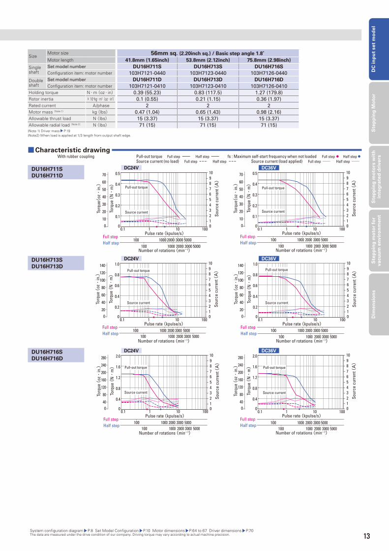
SizeMotor size 56mm sq. (2.20inch sq.) / Basic step angle 1.8°Motor length 41.8mm (1.65inch) 53.8mm (2.12inch) 75.8mm (2.98inch)
Single shaft
Set model number DU16H711S DU16H713S DU16H716S
Confi guration item: motor number 103H7121-0440 103H7123-0440 103H7126-0440
Double shaft
Set model number DU16H711D DU16H713D DU16H716D
Confi guration item: motor number 103H7121-0410 103H7123-0410 103H7126-0410
Holding torque N・m(oz・in) 0.39 (55.23) 0.83 (117.5) 1.27 (179.8)
Rotor inertia × 10-4kg・m2(oz・in2) 0.1 (0.55) 0.21 (1.15) 0.36 (1.97)
Rated current A/phase 2 2 2
Motor mass (Note 1) kg(lbs) 0.47 (1.04) 0.65 (1.43) 0.98 (2.16)
Allowable thrust load N (lbs) 15 (3.37) 15 (3.37) 15 (3.37)
Allowable radial load (Note 2) N (lbs) 71 (15) 71 (15) 71 (15)(Note 1) Driver mass P.19(Note2) When load is applied at 1/3 length from output shaft edge.
System confi guration diagram P.8 Set Model Confi guration P.10 Motor dimensions P.64 to 67 Driver dimensions P.70 The data are measured under the drive condition of our company. Driving torque may vary according to actual machine precision.
■ Characteristic drawing With rubber coupling fs : Maximum self-start frequency when not loaded Full step Half step Pull-out torque Full step Half step
Source current (load applied) Full step Half step Source current (no load) Full step Half step
DU16H711S
DU16H711D
DU16H713S
DU16H713D
DU16H716S
DU16H716D
DC24V
DC24V
DC24V
DC36V
DC36V
DC36V
Pulse rate (kpulse/s)
Number of rotations (min-1)
Torq
ue (
N・
m)
Sour
ce c
urre
nt (A)
0
0.2
0.4
0.6
0.8
1.0
0.1 1 10 100012345678910
Full stepHalf step
2000 3000 5000100 10002000 3000 5000100 1000
Pull-out torque
Source current
0
Torq
ue (
oz・
in.)
140
120
100
80
60
40
20
Pulse rate (kpulse/s)
Number of rotations (min-1)
Torq
ue (
N・
m)
Sour
ce c
urre
nt (A)
0
0.2
0.4
0.6
0.8
1.0
0.1 1 10 100012345678910
Full stepHalf step
Pull-out torque
Source current
0
Torq
ue (
oz・
in.)
140
120
100
80
60
40
20
2000 3000 5000100 10002000 3000 5000100 1000
Pulse rate (kpulse/s)
Number of rotations (min-1)
Torq
ue (
N・
m)
Sour
ce c
urre
nt (A)
0
0.4
0.8
1.2
1.6
2.0
0.1 1 10 100012345678910
Full stepHalf step
2000 3000 5000100 10002000 3000 5000100 1000
Pull-out torque
Source current
0
Torq
ue (
oz・
in.) 240
280
200
160
120
80
40
Pulse rate (kpulse/s)
Number of rotations (min-1)
Torq
ue (
N・
m)
Sour
ce c
urre
nt (A)
0
0.4
0.8
1.2
1.6
2.0
0.1 1 10 100012345678910
Full stepHalf step
2000 3000 5000100 10002000 3000 5000100 1000
Pull-out torque
Source current
0
Torq
ue (
oz・
in.) 240
280
200
160
120
80
40
13
14
DC input set model
Pulse rate (kpulse/s)
Number of rotations (min-1)
Torq
ue (
N・
m)
Sour
ce c
urre
nt (A)
0
0.02
0.04
0.06
0.08
0.1
0.1 1 10 100012345678910
Full stepHalf step
2000 3000 5000100 10002000 3000 5000100 1000
Pull-out torque
Source current
0
Torq
ue (
oz・
in.)
14
12
10
8
6
4
2
Pulse rate (kpulse/s)
Number of rotations (min-1)To
rque
(N・
m)
Sour
ce c
urre
nt (A)
0
0.02
0.04
0.06
0.08
0.1
0.1 1 10 100012345678910
Full stepHalf step
2000 3000 5000100 10002000 3000 5000100 1000
Pull-out torque
Source current
0
Torq
ue (
oz・
in.)
14
12
10
8
6
4
2
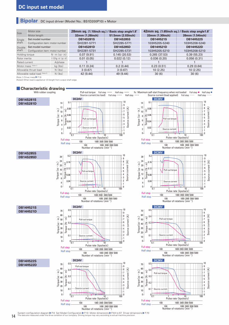
SizeMotor size 28mm sq. (1.10inch sq.) / Basic step angle1.8° 42mm sq. (1.65inch sq.) / Basic step angle1.8°Motor length 32mm (1.26inch) 51.5mm (2.03inch) 33mm (1.30inch) 39mm (1.54inch)
Single shaft
Set model number DB14S281S DB14S285S DB14H521S DB14H522S
Confi guration item: motor number SH2281-5771 SH2285-5771 103H5205-5240 103H5208-5240
Double shaft
Set model number DB14S281D DB14S285D DB14H521D DB14H522D
Confi guration item: motor number SH2281-5731 SH2285-5731 103H5205-5210 103H5208-5210
Holding torque N・m(oz・in) 0.07 (9.91) 0.145 (20.53) 0.265 (37.53) 0.39 (55.23)
Rotor inertia × 10-4kg・m2(oz・in2) 0.01 (0.05) 0.022 (0.12) 0.036 (0.20) 0.056 (0.31)
Rated current A/phase 1 1 1 1
Motor mass (Note 1) kg(lbs) 0.11 (0.24) 0.2 (0.44) 0.23 (0.51) 0.29 (0.64)
Allowable thrust load N (lbs) 3 (0.67) 3 (0.67) 10 (2.25) 10 (2.25)
Allowable radial load (Note 2) N (lbs) 42 (9.44) 49 (9.44) 30 (6) 30 (6) (Note 1) Driver mass P.19(Note2) When load is applied at 1/3 length from output shaft edge.
System confi guration diagram P.8 Set Model Confi guration P.10 Motor dimensions P.64 to 67 Driver dimensions P.70 The data are measured under the drive condition of our company. Driving torque may vary according to actual machine precision.
■ Characteristic drawing With rubber coupling fs : Maximum self-start frequency when not loaded Full step Half step Pull-out torque Full step Half step
Source current (load applied) Full step Half step Source current (no load) Full step Half step
DB14S281S
DB14S281D
DB14S285S
DB14S285D
DB14H521S
DB14H521D
DB14H522S
DB14H522D
DC24V
DC24V
DC24V
DC24V
DC36V
DC36V
DC36V
DC36V
Pulse rate (kpulse/s)
Number of rotations (min-1)
Torq
ue (
N・
m)
Sour
ce c
urre
nt (A)
0
0.04
0.08
0.12
0.16
0.2
0.1 1 10 100012345678910
Full stepHalf step
2000 3000 5000100 10002000 3000 5000100 1000
Pull-out torque
Source current
0
Torq
ue (
oz・
in.)
28
20
16
24
12
8
4
Pulse rate (kpulse/s)
Number of rotations (min-1)
Torq
ue (
N・
m)
Sour
ce c
urre
nt (A)
0
0.04
0.08
0.12
0.16
0.2
0.1 1 10 100012345678910
Full stepHalf step
2000 3000 5000100 10002000 3000 5000100 1000
Pull-out torque
Source current
0
Torq
ue (
oz・
in.)
28
20
16
24
12
8
4
Pulse rate (kpulse/s)
Number of rotations (min-1)
Torq
ue (
N・
m)
Sour
ce c
urre
nt (A)
0
0.1
0.2
0.3
0.4
0.5
0.1 1 10 100012345678910
Full stepHalf step
2000 3000 5000100 10002000 3000 5000100 1000
Pull-out torque
Source current
0
Torq
ue(oz・
in.)
70
60
50
40
30
20
10
Pulse rate (kpulse/s)
Number of rotations (min-1)
Torq
ue (
N・
m)
Sour
ce c
urre
nt (A)
0
0.1
0.2
0.3
0.4
0.5
0.1 1 10 100012345678910
Full stepHalf step 2000 3000 5000100 1000
2000 3000 5000100 1000
Pull-out torque
Source current
0
Torq
ue(oz・
in.)
70
60
50
40
30
20
10
Pulse rate (kpulse/s)
Number of rotations (min-1)
Torq
ue (
N・
m)
Sour
ce c
urre
nt (A)
0
0.1
0.2
0.3
0.4
0.5
0.1 1 10 100012345678910
Full stepHalf step 2000 3000 5000100 1000
2000 3000 5000100 1000
Pull-out torque
Source current
0
Torq
ue(oz・
in.)
70
60
50
40
30
20
10
Pulse rate (kpulse/s)
Number of rotations (min-1)
Torq
ue (
N・
m)
Sour
ce c
urre
nt (A)
0
0.1
0.2
0.3
0.4
0.5
0.1 1 10 100012345678910
Full stepHalf step 2000 3000 5000100 1000
2000 3000 5000100 1000
Pull-out torque
Source current
0
Torq
ue(oz・
in.)
70
60
50
40
30
20
10
Bipolar DC input driver (Model No.: BS1D200P10) + Motor

15
DC
in
pu
t se
t m
od
el
Ste
pp
ing
Mo
tor
Ste
pp
ing
mo
tors
wit
h
inte
gra
ted
dri
ve
rsS
tep
pin
g m
oto
r fo
r v
acu
um
en
vir
on
me
nt
Dim
en
sio
ns
System confi guration diagram P.8 Set Model Confi guration P.10 Motor dimensions P.64 to 67 Driver dimensions P.70 The data are measured under the drive condition of our company. Driving torque may vary according to actual machine precision.
Pulse rate (kpulse/s)
Number of rotations (min-1)
Torq
ue (
N・
m)
Sour
ce c
urre
nt (A)
0
0.2
0.4
0.6
0.8
1.0
0.1 1 10 100012345678910
Full stepHalf step 2000 3000 5000100 1000
2000 3000 5000100 1000
Pull-out torque
Source current
0
Torq
ue (
oz・
in.)
140
120
100
80
60
40
20
Pulse rate (kpulse/s)
Number of rotations (min-1)To
rque
(N・
m)
Sour
ce c
urre
nt (A)
0
0.2
0.4
0.6
0.8
1.0
0.1 1 10 100012345678910
Full stepHalf step 2000 3000 5000100 1000
2000 3000 5000100 1000
Pull-out torque
Source current
0
Torq
ue (
oz・
in.)
140
120
100
80
60
40
20
SizeMotor size 42mm sq. (1.65inch sq.) / Basic step angle1.8° 42mm sq. (1.65inch sq.) / Basic step angle 0.9°Motor length 48mm (1.89inch) 33mm (1.30inch) 39mm (1.54inch) 48mm (1.89inch)
Single shaft
Set model number DB14H524S DB16S141S DB16S142S DB16S144S
Confi guration item: motor number 103H5210-5240 SH1421-5241 SH1422-5241 SH1424-5241
Double shaft
Set model number DB14H524D DB16S141D DB16S142D DB16S144D
Confi guration item: motor number 103H5210-5210 SH1421-5211 SH1422-5211 SH1424-5211
Holding torque N・m(oz・in) 0.51 (72.22) 0.23 (32.57) 0.34 (48.15) 0.48 (67.97)
Rotor inertia × 10-4kg・m2(oz・in2) 0.074 (0.40) 0.044 (0.24) 0.066 (0.361) 0.089 (0.487)
Rated current A/phase 1 2 2 2
Motor mass (Note 1) kg(lbs) 0.37 (0.82) 0.24 (0.53) 0.29 (0.64) 0.38 (0.84)
Allowable thrust load N (lbs) 10 (2.25) 10 (2.25) 10 (2.25) 10 (2.25)
Allowable radial load (Note 2) N (lbs) 30 (6) 30 (6) 30 (6) 30 (6)(Note 1) Driver mass P.19(Note2) When load is applied at 1/3 length from output shaft edge.
■ Characteristic drawing With rubber coupling fs : Maximum self-start frequency when not loaded Full step Half step Pull-out torque Full step Half step
Source current (load applied) Full step Half step Source current (no load) Full step Half step
DB14H524S
DB14H524D
DB16S141S
DB16S141D
DB16S142S
DB16S142D
DB16S144S
DB16S144D
DC24V
DC24V
DC24V
DC24V
DC36V
DC36V
DC36V
DC36V
Pulse rate (kpulse/s)
Number of rotations (min-1)
Torq
ue (
N・
m)
Sour
ce c
urre
nt (A)
0
0.1
0.2
0.3
0.4
0.5
0.1 1 10 100012345678910
Full stepHalf step 2000 3000 5000100 1000
2000 3000 5000100 1000
Pull-out torque
Source current
0
Torq
ue(oz・
in.)
70
60
50
40
30
20
10
Pulse rate (kpulse/s)
Number of rotations (min-1)
Torq
ue (
N・
m)
Sour
ce c
urre
nt (A)
0
0.1
0.2
0.3
0.4
0.5
0.1 1 10 100012345678910
Full stepHalf step 2000 3000 5000100 1000
2000 3000 5000100 1000
Pull-out torque
Source current
0
Torq
ue(oz・
in.)
70
60
50
40
30
20
10
Pulse rate (kpulse/s)
Number of rotations (min-1)
Torq
ue (
N・
m)
Sour
ce c
urre
nt (A)
0
0.1
0.2
0.3
0.4
0.5
0.1 1 10 100012345678910
Full stepHalf step 2000 3000 5000100 1000
2000 3000 5000100 1000
Pull-out torque
Source current
0
Torq
ue(oz・
in.)
70
60
50
40
30
20
10
Pulse rate (kpulse/s)
Number of rotations (min-1)
Torq
ue (
N・
m)
Sour
ce c
urre
nt (A)
0
0.1
0.2
0.3
0.4
0.5
0.1 1 10 100012345678910
Full stepHalf step 2000 3000 5000100 1000
2000 3000 5000100 1000
Pull-out torque
Source current
0
Torq
ue(oz・
in.)
70
60
50
40
30
20
10
Pulse rate (kpulse/s)
Number of rotations (min-1)
Torq
ue (
N・
m)
Sour
ce c
urre
nt (A)
0
0.2
0.4
0.6
0.8
1.0
0.1 1 10 100012345678910
Full stepHalf step 2000 3000 5000100 1000
2000 3000 5000100 1000
Pull-out torque
Source current
0
Torq
ue (
oz・
in.)
140
120
100
80
60
40
20
Pulse rate (kpulse/s)
Number of rotations (min-1)
Torq
ue (
N・
m)
Sour
ce c
urre
nt (A)
0
0.2
0.4
0.6
0.8
1.0
0.1 1 10 100012345678910
Full stepHalf step 2000 3000 5000100 1000
2000 3000 5000100 1000
Pull-out torque
Source current
0
Torq
ue (
oz・
in.)
140
120
100
80
60
40
20
15
16
DC input set model
Pulse rate (kpulse/s)
Number of rotations (min-1)
Torq
ue (
N・
m)
Sour
ce c
urre
nt (A)
0
0.1
0.2
0.3
0.4
0.5
0.1 1 10 100012345678910
Full stepHalf step 2000 3000 5000100 1000
2000 3000 5000100 1000
Pull-out torque
Source current
0
Torq
ue(oz・
in.)
70
60
50
40
30
20
10
Pulse rate (kpulse/s)
Number of rotations (min-1)To
rque
(N・
m)
Sour
ce c
urre
nt (A)
0
0.1
0.2
0.3
0.4
0.5
0.1 1 10 100012345678910
Full stepHalf step 2000 3000 5000100 1000
2000 3000 5000100 1000
Pull-out torque
Source current
0
Torq
ue(oz・
in.)
70
60
50
40
30
20
10
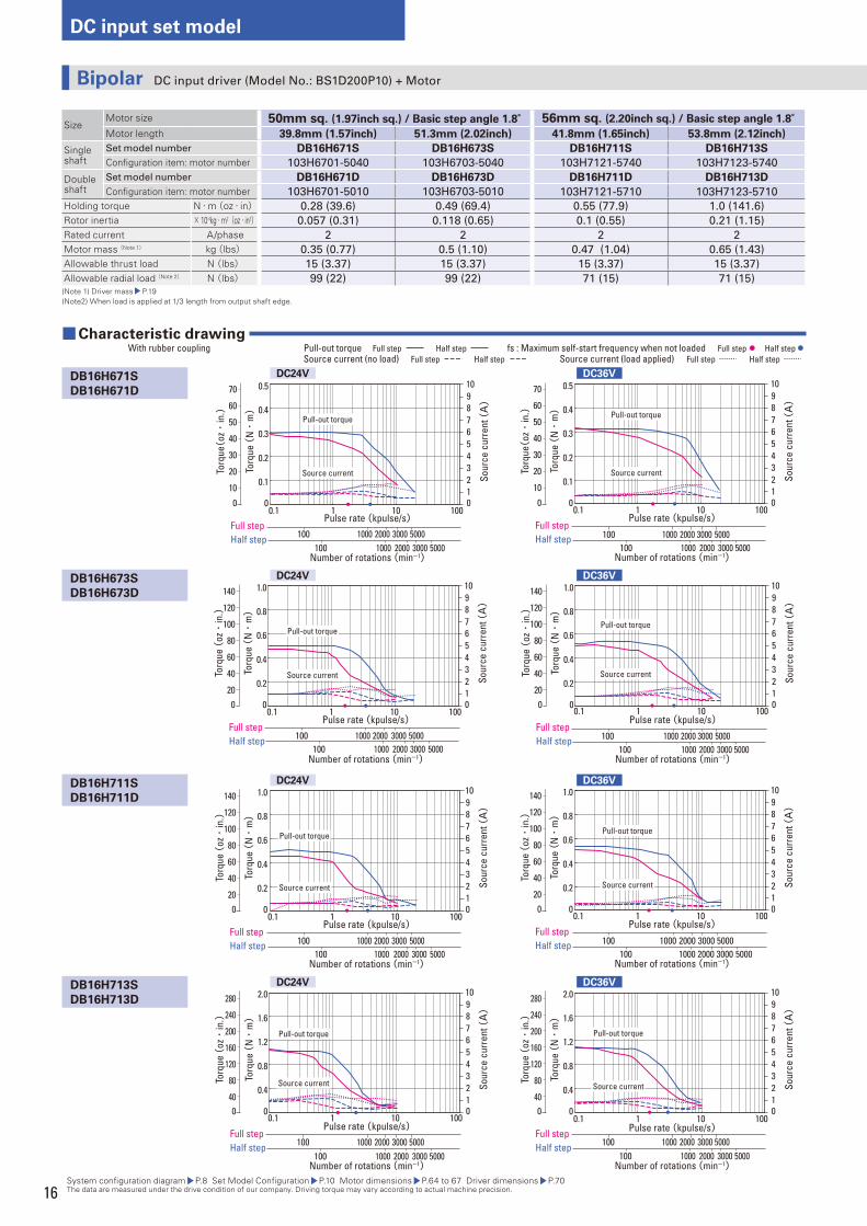
SizeMotor size 50mm sq. (1.97inch sq.) / Basic step angle 1.8° 56mm sq. (2.20inch sq.) / Basic step angle 1.8°Motor length 39.8mm (1.57inch) 51.3mm (2.02inch) 41.8mm (1.65inch) 53.8mm (2.12inch)
Single shaft
Set model number DB16H671S DB16H673S DB16H711S DB16H713S
Confi guration item: motor number 103H6701-5040 103H6703-5040 103H7121-5740 103H7123-5740
Double shaft
Set model number DB16H671D DB16H673D DB16H711D DB16H713D
Confi guration item: motor number 103H6701-5010 103H6703-5010 103H7121-5710 103H7123-5710
Holding torque N・m(oz・in) 0.28 (39.6) 0.49 (69.4) 0.55 (77.9) 1.0 (141.6)
Rotor inertia × 10-4kg・m2(oz・in2) 0.057 (0.31) 0.118 (0.65) 0.1 (0.55) 0.21 (1.15)
Rated current A/phase 2 2 2 2
Motor mass (Note 1) kg(lbs) 0.35 (0.77) 0.5 (1.10) 0.47 (1.04) 0.65 (1.43)
Allowable thrust load N (lbs) 15 (3.37) 15 (3.37) 15 (3.37) 15 (3.37)
Allowable radial load (Note 2) N (lbs) 99 (22) 99 (22) 71 (15) 71 (15) (Note 1) Driver mass P.19(Note2) When load is applied at 1/3 length from output shaft edge.
System confi guration diagram P.8 Set Model Confi guration P.10 Motor dimensions P.64 to 67 Driver dimensions P.70 The data are measured under the drive condition of our company. Driving torque may vary according to actual machine precision.
■ Characteristic drawing With rubber coupling fs : Maximum self-start frequency when not loaded Full step Half step Pull-out torque Full step Half step
Source current (load applied) Full step Half step Source current (no load) Full step Half step
DB16H671S
DB16H671D
DB16H673S
DB16H673D
DB16H711S
DB16H711D
DB16H713S
DB16H713D
DC24V
DC24V
DC24V
DC24V
DC36V
DC36V
DC36V
DC36V
Pulse rate (kpulse/s)
Number of rotations (min-1)
Torq
ue (
N・
m)
Sour
ce c
urre
nt (A)
0
0.2
0.4
0.6
0.8
1.0
0.1 1 10 100012345678910
Full stepHalf step
Pull-out torque
Source current
0
Torq
ue (
oz・
in.)
140
120
100
80
60
40
20
2000 3000 5000100 10002000 3000 5000100 1000
Pulse rate (kpulse/s)
Number of rotations (min-1)
Torq
ue (
N・
m)
Sour
ce c
urre
nt (A)
0
0.2
0.4
0.6
0.8
1.0
0.1 1 10 100012345678910
Full stepHalf step
Pull-out torque
Source current
0
Torq
ue (
oz・
in.)
140
120
100
80
60
40
20
2000 3000 5000100 10002000 3000 5000100 1000
Pulse rate (kpulse/s)
Number of rotations (min-1)
Torq
ue (
N・
m)
Sour
ce c
urre
nt (A)
0
0.2
0.4
0.6
0.8
1.0
0.1 1 10 100012345678910
Full stepHalf step 2000 3000 5000100 1000
2000 3000 5000100 1000
Pull-out torque
Source current
0
Torq
ue (
oz・
in.)
140
120
100
80
60
40
20
Pulse rate (kpulse/s)
Number of rotations (min-1)
Torq
ue (
N・
m)
Sour
ce c
urre
nt (A)
0
0.2
0.4
0.6
0.8
1.0
0.1 1 10 100012345678910
Full stepHalf step 2000 3000 5000100 1000
2000 3000 5000100 1000
Pull-out torque
Source current
0
Torq
ue (
oz・
in.)
140
120
100
80
60
40
20
Pulse rate (kpulse/s)
Number of rotations (min-1)
Torq
ue (
N・
m)
Sour
ce c
urre
nt (A)
0
0.4
0.8
1.2
1.6
2.0
0.1 1 10 100012345678910
Full stepHalf step 2000 3000 5000100 1000
2000 3000 5000100 1000
Pull-out torque
Source current
0
Torq
ue (
oz・
in.) 240
280
200
160
120
80
40
Pulse rate (kpulse/s)
Number of rotations (min-1)
Torq
ue (
N・
m)
Sour
ce c
urre
nt (A)
0
0.4
0.8
1.2
1.6
2.0
0.1 1 10 100012345678910
Full stepHalf step 2000 3000 5000100 1000
2000 3000 5000100 1000
Pull-out torque
Source current
0
Torq
ue (
oz・
in.) 240
280
200
160
120
80
40
Bipolar DC input driver (Model No.: BS1D200P10) + Motor
17
DC
in
pu
t se
t m
od
el
Ste
pp
ing
Mo
tor
Ste
pp
ing
mo
tors
wit
h
inte
gra
ted
dri
ve
rsS
tep
pin
g m
oto
r fo
r v
acu
um
en
vir
on
me
nt
Dim
en
sio
ns
System confi guration diagram P.8 Set Model Confi guration P.10 Motor dimensions P.64 to 67 Driver dimensions P.70 The data are measured under the drive condition of our company. Driving torque may vary according to actual machine precision.
Pulse rate (kpulse/s)
Number of rotations (min-1)
Torq
ue (
N・
m)
Sour
ce c
urre
nt (A)
0
0.4
0.8
1.2
1.6
2.0
0.1 1 10 100012345678910
Full stepHalf step 2000 3000 5000100 1000
2000 3000 5000100 1000
Pull-out torque
Source current
0
Torq
ue (
oz・
in.) 240
280
200
160
120
80
40
Pulse rate (kpulse/s)
Number of rotations (min-1)To
rque
(N・
m)
Sour
ce c
urre
nt (A)
0
0.4
0.8
1.2
1.6
2.0
0.1 1 10 100012345678910
Full stepHalf step 2000 3000 5000100 1000
2000 3000 5000100 1000
Pull-out torque
Source current
0
Torq
ue (
oz・
in.) 240
280
200
160
120
80
40
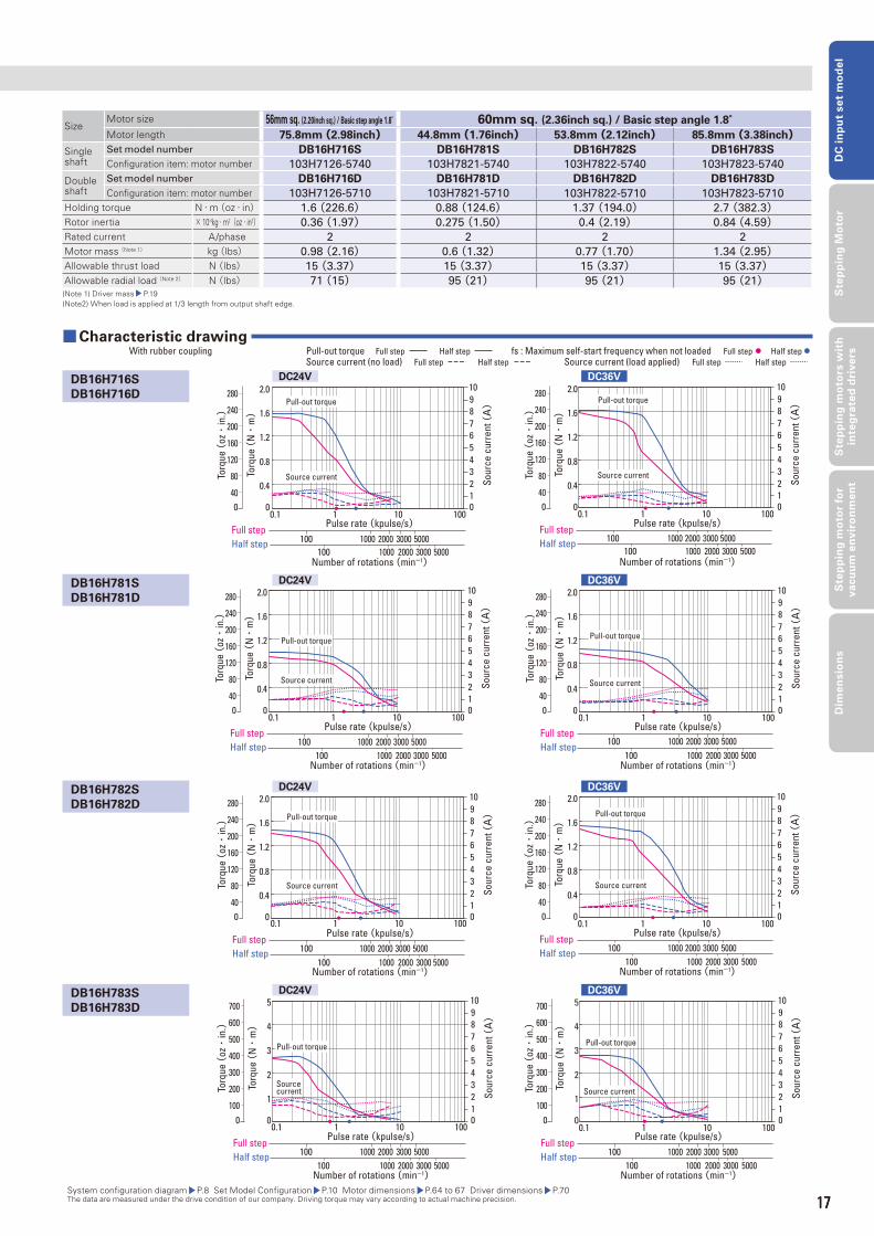
SizeMotor size 56mm sq. (2.20inch sq.) / Basic step angle 1.8° 60mm sq. (2.36inch sq.) / Basic step angle 1.8°Motor length 75.8mm (2.98inch) 44.8mm (1.76inch) 53.8mm (2.12inch) 85.8mm (3.38inch)
Single shaft
Set model number DB16H716S DB16H781S DB16H782S DB16H783S
Confi guration item: motor number 103H7126-5740 103H7821-5740 103H7822-5740 103H7823-5740
Double shaft
Set model number DB16H716D DB16H781D DB16H782D DB16H783D
Confi guration item: motor number 103H7126-5710 103H7821-5710 103H7822-5710 103H7823-5710
Holding torque N・m(oz・in) 1.6 (226.6) 0.88 (124.6) 1.37 (194.0) 2.7 (382.3)Rotor inertia × 10-4kg・m2(oz・in2) 0.36 (1.97) 0.275 (1.50) 0.4 (2.19) 0.84 (4.59)Rated current A/phase 2 2 2 2
Motor mass (Note 1) kg(lbs) 0.98 (2.16) 0.6 (1.32) 0.77 (1.70) 1.34 (2.95)Allowable thrust load N (lbs) 15 (3.37) 15 (3.37) 15 (3.37) 15 (3.37)Allowable radial load (Note 2) N (lbs) 71 (15) 95 (21) 95 (21) 95 (21)(Note 1) Driver mass P.19(Note2) When load is applied at 1/3 length from output shaft edge.
■ Characteristic drawing With rubber coupling fs : Maximum self-start frequency when not loaded Full step Half step Pull-out torque Full step Half step
Source current (load applied) Full step Half step Source current (no load) Full step Half step
DB16H716S
DB16H716D
DB16H781S
DB16H781D
DB16H782S
DB16H782D
DB16H783S
DB16H783D
DC24V
DC24V
DC24V
DC24V
DC36V
DC36V
DC36V
DC36V
Pulse rate (kpulse/s)
Number of rotations (min-1)
Torq
ue (
N・
m)
Sour
ce c
urre
nt (A)
0
0.4
0.8
1.2
1.6
2.0
0.1 1 10 100012345678910
Full stepHalf step 2000 3000 5000100 1000
2000 3000 5000100 1000
Pull-out torque
Source current
0
Torq
ue (
oz・
in.) 240
280
200
160
120
80
40
Pulse rate (kpulse/s)
Number of rotations (min-1)
Torq
ue (
N・
m)
Sour
ce c
urre
nt (A)
0
0.4
0.8
1.2
1.6
2.0
0.1 1 10 100012345678910
Full stepHalf step 2000 3000 5000100 1000
2000 3000 5000100 1000
Pull-out torque
Source current
0
Torq
ue (
oz・
in.) 240
280
200
160
120
80
40
Pulse rate (kpulse/s)
Number of rotations (min-1)
Torq
ue (
N・
m)
Sour
ce c
urre
nt (A)
0
0.4
0.8
1.2
1.6
2.0
0.1 1 10 100012345678910
Full stepHalf step 2000 3000 5000100 1000
2000 3000 5000100 1000
Pull-out torque
Source current
0
Torq
ue (
oz・
in.) 240
280
200
160
120
80
40
Pulse rate (kpulse/s)
Number of rotations (min-1)
Torq
ue (
N・
m)
Sour
ce c
urre
nt (A)
0
0.4
0.8
1.2
1.6
2.0
0.1 1 10 100012345678910
Full stepHalf step 2000 3000 5000100 1000
2000 3000 5000100 1000
Pull-out torque
Source current
0
Torq
ue (
oz・
in.) 240
280
200
160
120
80
40
Pulse rate (kpulse/s)
Number of rotations (min-1)
Torq
ue (
N・
m)
Sour
ce c
urre
nt (A)
0
1
2
3
4
5
0.1 1 10 100012345678910
Full stepHalf step 2000 3000 5000100 1000
2000 3000 5000100 1000
Pull-out torque
Source current
0
Torq
ue (
oz・
in.)
700
600
500
400
300
200
100
Pulse rate (kpulse/s)
Number of rotations (min-1)
Torq
ue (
N・
m)
Sour
ce c
urre
nt (A)
0
1
2
3
4
5
0.1 1 10 100012345678910
Full stepHalf step 2000 3000 5000100 1000
2000 3000 5000100 1000
Pull-out torque
Source current
0
Torq
ue (
oz・
in.)
700
600
500
400
300
200
100
17
18
DC input set model
Pulse rate (kpulse/s)
Number of rotations (min-1)
Torq
ue (
N・
m)
Sour
ce c
urre
nt (A)
0
0.2
0.4
0.6
0.8
1.0
0.1 1 10 100012345678910
Full stepHalf step 2000 3000 5000100 1000
2000 3000 5000100 1000
Pull-out torque
Source current
0
Torq
ue (
oz・
in.)
140
120
100
80
60
40
20
Pulse rate (kpulse/s)
Number of rotations (min-1)To
rque
(N・
m)
Sour
ce c
urre
nt (A)
0
0.2
0.4
0.6
0.8
1.0
0.1 1 10 100012345678910
Full stepHalf step
2000 3000 5000100 10002000 3000 5000100 1000
Pull-out torque
Source current
0
Torq
ue (
oz・
in.)
140
120
100
80
60
40
20
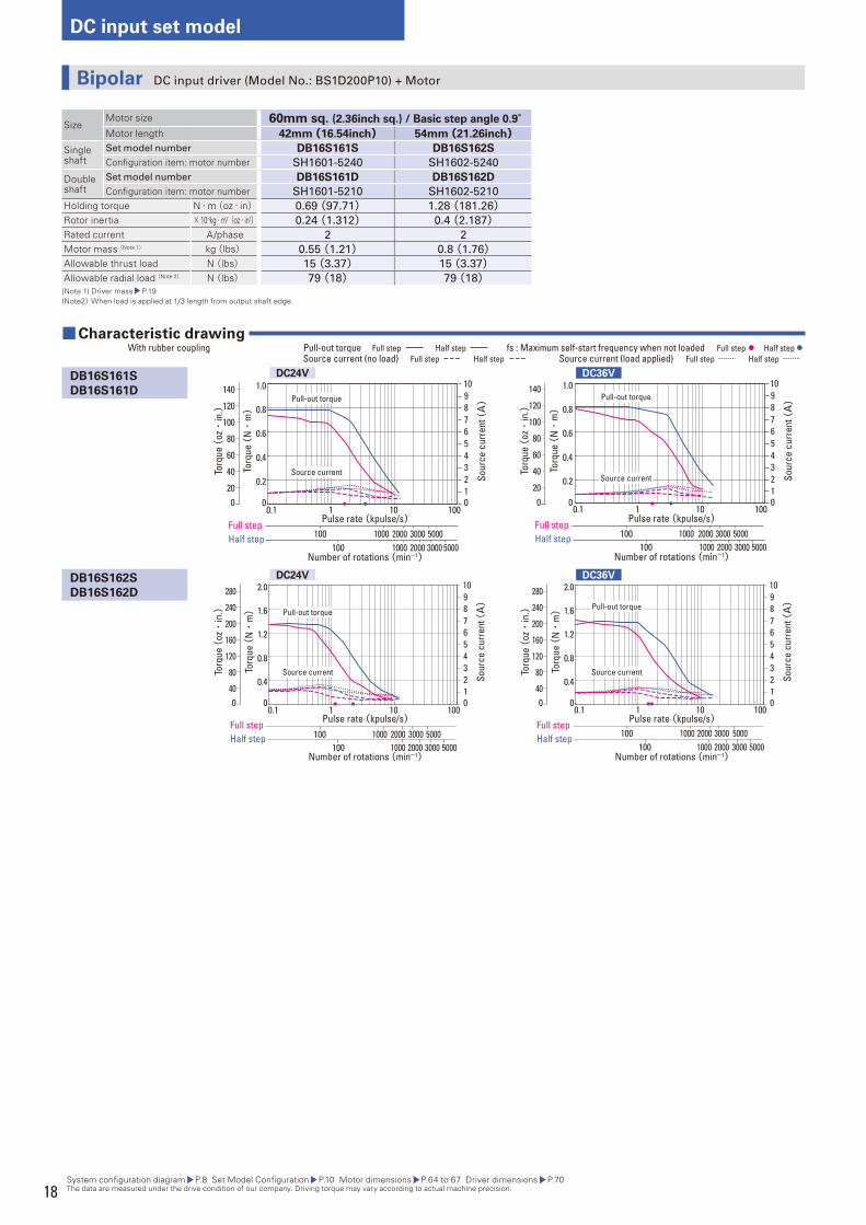
SizeMotor size 60mm sq. (2.36inch sq.) / Basic step angle 0.9°Motor length 42mm (16.54inch) 54mm (21.26inch)
Single shaft
Set model number DB16S161S DB16S162S
Confi guration item: motor number SH1601-5240 SH1602-5240
Double shaft
Set model number DB16S161D DB16S162D
Confi guration item: motor number SH1601-5210 SH1602-5210
Holding torque N・m(oz・in) 0.69 (97.71) 1.28 (181.26)Rotor inertia × 10-4kg・m2(oz・in2) 0.24 (1.312) 0.4 (2.187)Rated current A/phase 2 2
Motor mass (Note 1) kg(lbs) 0.55 (1.21) 0.8 (1.76)Allowable thrust load N (lbs) 15 (3.37) 15 (3.37)Allowable radial load (Note 2) N (lbs) 79 (18) 79 (18)(Note 1) Driver mass P.19(Note2) When load is applied at 1/3 length from output shaft edge.
System confi guration diagram P.8 Set Model Confi guration P.10 Motor dimensions P.64 to 67 Driver dimensions P.70 The data are measured under the drive condition of our company. Driving torque may vary according to actual machine precision.
■ Characteristic drawing With rubber coupling fs : Maximum self-start frequency when not loaded Full step Half step Pull-out torque Full step Half step
Source current (load applied) Full step Half step Source current (no load) Full step Half step
DB16S161S
DB16S161D
DB16S162S
DB16S162D
DC24V
DC24V
DC36V
DC36V
Pulse rate (kpulse/s)
Number of rotations (min-1)
Torq
ue (
N・
m)
Sour
ce c
urre
nt (A)
0
0.4
0.8
1.2
1.6
2.0
0.1 1 10 100012345678910
Full stepHalf step
2000 3000 5000100 10002000 3000 5000100 1000
Pull-out torque
Source current
0
Torq
ue (
oz・
in.) 240
280
200
160
120
80
40
Pulse rate (kpulse/s)
Number of rotations (min-1)
Torq
ue (
N・
m)
Sour
ce c
urre
nt (A)
0
0.4
0.8
1.2
1.6
2.0
0.1 1 10 100012345678910
Full stepHalf step
2000 3000 5000100 10002000 3000 5000100 1000
Pull-out torque
Source current
0
Torq
ue (
oz・
in.) 240
280
200
160
120
80
40
Bipolar DC input driver (Model No.: BS1D200P10) + Motor
19
DC
in
pu
t se
t m
od
el
Ste
pp
ing
Mo
tor
Ste
pp
ing
mo
tors
wit
h
inte
gra
ted
dri
ve
rsS
tep
pin
g m
oto
r fo
r v
acu
um
en
vir
on
me
nt
Dim
en
sio
ns
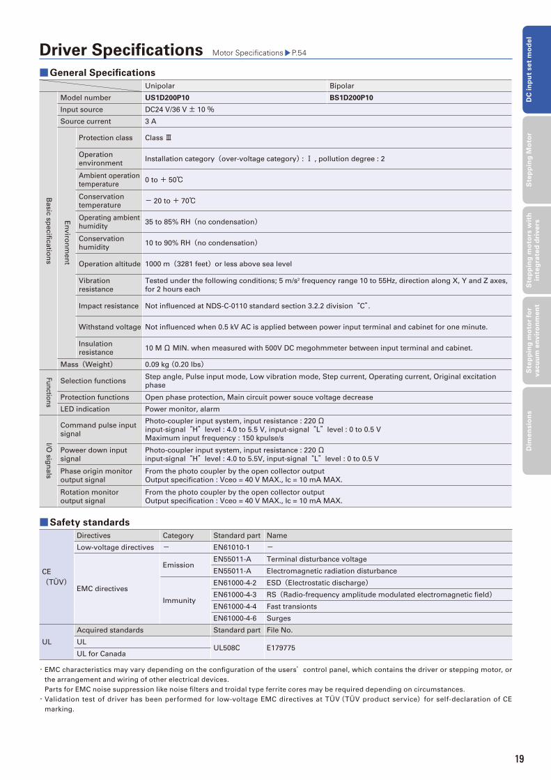
Driver Specifi cations Motor Specifi cations P.54
■ General Specifi cations
Unipolar Bipolar
Ba
sic
sp
ecifi c
atio
ns
Model number US1D200P10 BS1D200P10
Input source DC24 V/36 V± 10 %Source current 3 A
En
viro
nm
en
t
Protection class Class Ⅲ
Operation
environmentInstallation category(over-voltage category) : Ⅰ , pollution degree : 2
Ambient operation
temperature0 to + 50℃
Conservation
temperature- 20 to + 70℃
Operating ambient
humidity35 to 85% RH(no condensation)
Conservation
humidity10 to 90% RH(no condensation)
Operation altitude 1000 m(3281 feet)or less above sea level
Vibration
resistance
Tested under the following conditions; 5 m/s2 frequency range 10 to 55Hz, direction along X, Y and Z axes,
for 2 hours each
Impact resistance Not infl uenced at NDS-C-0110 standard section 3.2.2 division“C”.
Withstand voltage Not infl uenced when 0.5 kV AC is applied between power input terminal and cabinet for one minute.
Insulation
resistance10 MΩ MIN. when measured with 500V DC megohmmeter between input terminal and cabinet.
Mass(Weight) 0.09 kg (0.20 lbs)
Fu
nctio
ns
Selection functionsStep angle, Pulse input mode, Low vibration mode, Step current, Operating current, Original excitation
phase
Protection functions Open phase protection, Main circuit power souce voltage decrease
LED indication Power monitor, alarm
I/O s
ign
als
Command pulse input
signal
Photo-coupler input system, input resistance : 220Ωinput-signal“H”level : 4.0 to 5.5 V, input-signal“L”level : 0 to 0.5 V
Maximum input frequency : 150 kpulse/s
Poweer down input
signal
Photo-coupler input system, input resistance : 220Ωinput-signal“H”level : 4.0 to 5.5V, input-signal“L”level : 0 to 0.5 V
Phase origin monitor
output signal
From the photo coupler by the open collector output
Output specifi cation : Vceo = 40 V MAX., Ic = 10 mA MAX.
Rotation monitor
output signal
From the photo coupler by the open collector output
Output specifi cation : Vceo = 40 V MAX., Ic = 10 mA MAX.
■Safety standards
CE
(TÜV)
Directives Category Standard part Name
Low-voltage directives - EN61010-1 -
EMC directives
EmissionEN55011-A Terminal disturbance voltage
EN55011-A Electromagnetic radiation disturbance
Immunity
EN61000-4-2 ESD(Electrostatic discharge)EN61000-4-3 RS(Radio-frequency amplitude modulated electromagnetic fi eld)EN61000-4-4 Fast transionts
EN61000-4-6 Surges
UL
Acquired standards Standard part File No.
ULUL508C E179775
UL for Canada
・ EMC characteristics may vary depending on the confi guration of the users’control panel, which contains the driver or stepping motor, or
the arrangement and wiring of other electrical devices.
Parts for EMC noise suppression like noise fi lters and troidal type ferrite cores may be required depending on circumstances.
・ Validation test of driver has been performed for low-voltage EMC directives at TÜV(TÜV product service)for self-declaration of CE
marking.
19
20
DC input set model
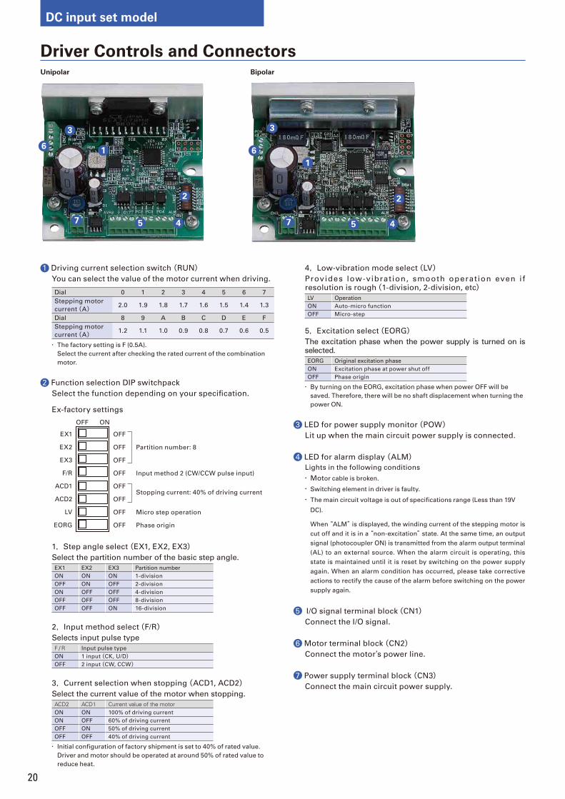
Driver Controls and ConnectorsUnipolar Bipolar
1 Driving current selection switch (RUN)You can select the value of the motor current when driving.
Dial 0 1 2 3 4 5 6 7
Stepping motor
current(A) 2.0 1.9 1.8 1.7 1.6 1.5 1.4 1.3
Dial 8 9 A B C D E F
Stepping motor
current(A) 1.2 1.1 1.0 0.9 0.8 0.7 0.6 0.5
・ The factory setting is F (0.5A).
Select the current after checking the rated current of the combination
motor.
2 Function selection DIP switchpack
Select the function depending on your specifi cation.
Ex-factory settings
EX1
EX2
EX3
F/R
ACD1
ACD2
LV
EORG
OFF
OFF Partition number: 8
OFF
OFF Input method 2 (CW/CCW pulse input)
OFF Stopping current: 40% of driving current
OFF
OFF Micro step operation
OFF Phase origin
OFF ON
1,Step angle select (EX1, EX2, EX3)Select the partition number of the basic step angle.
EX1 EX2 EX3 Partition number
ON ON ON 1-division
OFF ON OFF 2-division
ON OFF OFF 4-division
OFF OFF OFF 8-division
OFF OFF ON 16-division
2,Input method select(F/R)Selects input pulse type
F / R Input pulse type
ON 1 input(CK, U/D)OFF 2 input(CW, CCW)
3,Current selection when stopping (ACD1, ACD2)Select the current value of the motor when stopping.
ACD2 ACD1 Current value of the motorON ON 100% of driving current
ON OFF 60% of driving current
OFF ON 50% of driving current
OFF OFF 40% of driving current
・ Initial confi guration of factory shipment is set to 40% of rated value.
Driver and motor should be operated at around 50% of rated value to
reduce heat.
4,Low-vibration mode select(LV)Provides low-vibration, smooth operation even i f resolution is rough(1-division, 2-division, etc)LV Operation
ON Auto-micro function
OFF Micro-step
5,Excitation select(EORG)The excitation phase when the power supply is turned on is selected.
EORG Original excitation phase
ON Excitation phase at power shut off
OFF Phase origin
・ By turning on the EORG, excitation phase when power OFF will be
saved. Therefore, there will be no shaft displacement when turning the
power ON.
3 LED for power supply monitor(POW)Lit up when the main circuit power supply is connected.
4 LED for alarm display (ALM)Lights in the following conditions
・ Motor cable is broken.
・ Switching element in driver is faulty.
・ The main circuit voltage is out of specifi cations range (Less than 19V
DC).
When “ALM” is displayed, the winding current of the stepping motor is
cut off and it is in a “non-excitation” state. At the same time, an output
signal (photocoupler ON) is transmitted from the alarm output terminal
(AL) to an external source. When the alarm circuit is operating, this
state is maintained until it is reset by switching on the power supply
again. When an alarm condition has occurred, please take corrective
actions to rectify the cause of the alarm before switching on the power
supply again.
5 I/O signal terminal block(CN1)Connect the I/O signal.
6 Motor terminal block (CN2)Connect the motor’s power line.
7 Power supply terminal block (CN3)Connect the main circuit power supply.
7 5 4
3
16
2
5
3
6
2
4
1
7
21
DC
in
pu
t se
t m
od
el
Ste
pp
ing
Mo
tor
Ste
pp
ing
mo
tors
wit
h
inte
gra
ted
dri
ve
rsS
tep
pin
g m
oto
r fo
r v
acu
um
en
vir
on
me
nt
Dim
en
sio
ns
Unipolar Bipolar
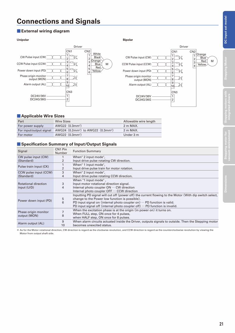
Connections and Signals
■External wiring diagram
■Applicable Wire Sizes
Part Wire Sizes Allowable wire length
For power supply AWG22(0.3mm2) 2 m MAX.
For input/output signal AWG24(0.2mm2)to AWG22(0.3mm2) 2 m MAX.
For motor AWG22(0.3mm2) Under 3 m
■Specifi cation Summary of Input/Output Signals
SignalCN1 Pin
NumberFunction Summary
CW pulse input (CW)
(Standard)
1
2
When" 2 input mode",
Input drive pulse rotating CW direction.
Pulse train input (CK)1
2
When" 1 input mode",
Input drive pulse train for motor rotation.
CCW pulse input (CCW)
(Standard)
3
4
When" 2 input mode",
Input drive pulse rotating CCW direction.
Rotational direction
input (U/D)
3
4
When "1 input mode" ,
Input motor rotational direction signal.
Internal photo coupler ON … CW direction
Internal photo coupler OFF … CCW direction
Power down input (PD)5
6
Inputting PD signal will cut off (power off) the current fl owing to the Motor (With dip switch select,
change to the Power low function is possible).PD input signal on (internal photo coupler on)… PD function is valid.
PD input signal off (internal photo coupler off)… PD function is invalid.
Phase origin monitor
output (MON)
7
8
When the excitation phase is at the origin (in power on) it turns on.
When FULL step, ON once for 4 pulses,
when HALF step, ON once for 8 pulses.
Alarm output (AL)9
10
When alarm circuits actuated inside the Driver, outputs signals to outside. Then the Stepping motor
becomes unexcited status.
※ As for the Motor rotational direction, CW direction is regard as the clockwise revolution, and CCW direction is regard as the counterclockwise revolution by viewing the
Motor from output shaft side.
DC24G/36G
DC24V/36V
CW Pulse input (CW)
CCW Pulse input (CCW)
Power down input (PD)
Phase origin monitoroutput (MON)
Alarm output (AL)
Driver
22
4
1
2
5
6
7
8
9
10
CN3
3M
6
5
4
3
1
CN1White
Black
Orange
Blue
Red
Yellow
1
CN2Orange
Blue
Red
Yellow
11CW Pulse input (CW)
CCW Pulse input (CCW)
Power down input (PD)
Phase origin monitor
output (MON)
Alarm output (AL)
DC24V/36V
DC24G/36G
3
4
2
4
CN3
10
9
8
7
6
5
2
1
3
2
CN2CN1
M
Driver
21
22
DC input set model
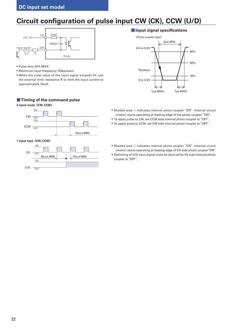
Circuit confi guration of pulse input CW (CK), CCW (U/D)
+5V1(3)
2(4)
R
220Ω
1000pFInput signal
Driver
• Pulse duty 50% MAX.
• Maximum input frequency:150kpulse/s
• When the crest value of the input signal exceeds 5V, use
the external limit resistance R to limit the input current to
approximately 15mA.
1μs MAX.
3μs MIN.
1μs MAX.
90%
4.0 to 5.5V
0 to 0.5V
Rotation
50%
10%
〈Photo coupler type〉
ON
OFFON
OFF
CW
CCW
50μs MIN.
1 input type(CW, CCW)
CK
U/D
ON
OFF
ON
OFF
50μs MIN. 10μs MIN.
• Shaded area indicates internal photo coupler“ON”. Internal circuit
(motor) starts operating at leading edge of the photo coupler“ON”.• To apply pulse to CW, set CCW side internal photo coupler to“OFF”.• To apply pulse to CCW, set CW side internal photo coupler to“OFF”.
• Shaded area indicates internal photo coupler “ON”. Internal circuit
(motor) starts operating at leading edge of CK side photo coupler“ON”.• Switching of U/D input signal must be done while CK side internal photo
coupler is“OFF”.
■ Input signal specifi cations
■Timing of the command pulse
2 input mode(CW, CCW)
23
DC
in
pu
t se
t m
od
el
Ste
pp
ing
Mo
tor
Ste
pp
ing
mo
tors
wit
h
inte
gra
ted
dri
ve
rsS
tep
pin
g m
oto
r fo
r v
acu
um
en
vir
on
me
nt
Dim
en
sio
ns
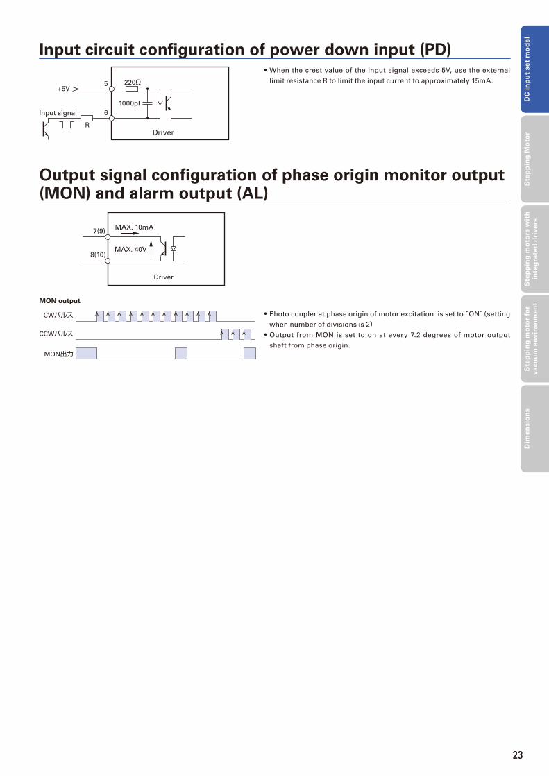
+5V5
6
R
220Ω
1000pF
Input signal
Driver
• When the crest value of the input signal exceeds 5V, use the external
limit resistance R to limit the input current to approximately 15mA.
Output signal confi guration of phase origin monitor output (MON) and alarm output (AL)
7(9)
8(10)
MAX. 10mA
MAX. 40V
Driver
CWパルス
CCWパルス
MON出力
• Photo coupler at phase origin of motor excitation is set to “ON”.(setting
when number of divisions is 2)• Output from MON is set to on at every 7.2 degrees of motor output
shaft from phase origin.
Input circuit confi guration of power down input (PD)
MON output
23
24
Stepping Motor
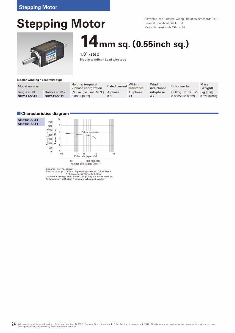
Allowable load・Internal wiring・Rotation direction P.53 General Specifications P.54 Motor dimensions P.64 The data are measured under the drive condition of our company. Driving torque may vary according to actual machine precision.
14mm sq.(0.55inch sq.)1.8°/stepBipolar winding・Lead wire type
Bipolar winding・Lead wire type
Model numberHolding torque at
2-phase energizationRated current
Wiring
resistance
Winding
inductanceRotor inertia
Mass
(Weight)
Single shaft Double shafts [N・m(oz・in)MIN.] A/phase Ω /phase mH/phase [×10-4kg・m2 (oz・in2)] [kg (Ibs)]
SH2141-5541 SH2141-5511 0.0065 (0.92) 0.3 21 4.2 0.00058 (0.0032) 0.028 (0.062)
Stepping MotorAllowable load・Internal wiring・Rotation direction P.53General Specifi cations P.54 Motor dimensions P.64 to 69
Constant current circuitSource voltage : DC24V・Operating current : 0.3A/phase, 2-phase energization (full-step)JL=[0.01× 10⁻⁴kg・m2 (1.80 oz・in2) pulley balancer method]fs: Maximum self-start frequency when not loaded
■Characteristics diagram
SH2141-5541
SH2141-5511
Torq
ue (
N・
m)
00.1
100 1000 2000 3000
1 10 100
2
4
6
8
10
Pulse rate (kpulse/s)
Number of rotations (min-1)
fs
Pull-out torque at JL
0
Torq
ue (
oz・
in.)
1400
1200
1000
800
600
400
200
25
DC
in
pu
t se
t m
od
el
Ste
pp
ing
Mo
tor
Ste
pp
ing
mo
tors
wit
h
inte
gra
ted
dri
ve
rsS
tep
pin
g m
oto
r fo
r v
acu
um
en
vir
on
me
nt
Dim
en
sio
ns
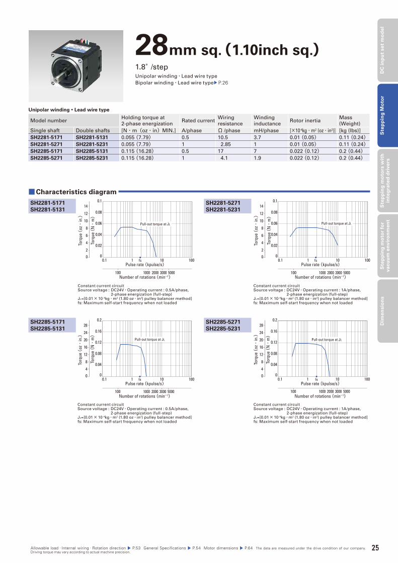
28mm sq.(1.10inch sq.)1.8°/stepUnipolar winding・Lead wire type
Bipolar winding・Lead wire type P.26
Unipolar winding・Lead wire type
Model numberHolding torque at
2-phase energizationRated current
Wiring
resistance
Winding
inductanceRotor inertia
Mass
(Weight)
Single shaft Double shafts [N・m(oz・in)MIN.] A/phase Ω /phase mH/phase [×10-4kg・m2 (oz・in2)] [kg (Ibs)]
SH2281-5171 SH2281-5131 0.055 (7.79) 0.5 10.5 3.7 0.01 (0.05) 0.11 (0.24)SH2281-5271 SH2281-5231 0.055 (7.79) 1 2.85 1 0.01 (0.05) 0.11 (0.24)SH2285-5171 SH2285-5131 0.115 (16.28) 0.5 17 7 0.022 (0.12) 0.2 (0.44)SH2285-5271 SH2285-5231 0.115 (16.28) 1 4.1 1.9 0.022 (0.12) 0.2 (0.44)
Constant current circuitSource voltage : DC24V・Operating current : 0.5A/phase, 2-phase energization (full-step)JL=[0.01× 10⁻⁴kg・m2 (1.80 oz・in2) pulley balancer method]fs: Maximum self-start frequency when not loaded
Constant current circuitSource voltage : DC24V・Operating current : 1A/phase, 2-phase energization (full-step)JL=[0.01× 10⁻⁴kg・m2 (1.80 oz・in2) pulley balancer method]fs: Maximum self-start frequency when not loaded
SH2281-5271
SH2281-5231
■Characteristics diagram
SH2281-5171
SH2281-5131
SH2285-5171
SH2285-5131
SH2285-5271
SH2285-5231
Constant current circuitSource voltage : DC24V・Operating current : 0.5A/phase, 2-phase energization (full-step)JL=[0.01× 10⁻⁴kg・m2 (1.80 oz・in2) pulley balancer method]fs: Maximum self-start frequency when not loaded
Constant current circuitSource voltage : DC24V・Operating current : 1A/phase, 2-phase energization (full-step)JL=[0.01× 10⁻⁴kg・m2 (1.80 oz・in2) pulley balancer method]fs: Maximum self-start frequency when not loaded
Pulse rate (kpulse/s)
Number of rotations (min-1)
fs
Torq
ue (
N・
m)
0.1 1 10 100
1000 2000 3000 5000100
0.02
0.04
0.06
0.08
0.1
0
Pull-out torque at JL
0
Torq
ue (
oz・
in.)
14
12
10
8
6
4
2
Pulse rate (kpulse/s)
Number of rotations (min-1)
fs
Torq
ue (
N・
m)
0.1 1 10 100
1000 2000 3000 5000100
0.02
0.04
0.06
0.08
0.1
0
Pull-out torque at JL
0To
rque
(oz・
in.)
14
12
10
8
6
4
2
Pulse rate (kpulse/s)
Number of rotations (min-1)
fs
Torq
ue (
N・
m)
0.1 1 10 100
1000 2000 3000 5000100
0.04
0.08
0.12
0.16
0.2
0
Pull-out torque at JL
0
Torq
ue (
oz・
in.)
24
28
20
16
12
4
8
Pulse rate (kpulse/s)
Number of rotations (min-1)
fs
Torq
ue (
N・
m)
0.1 1 10 100
1000 2000 3000 5000100
0.04
0.08
0.12
0.16
0.2
0
Pull-out torque at JL
0
Torq
ue (
oz・
in.)
24
28
20
16
12
4
8
Allowable load・Internal wiring・Rotation direction P.53 General Specifications P.54 Motor dimensions P.64 The data are measured under the drive condition of our company. Driving torque may vary according to actual machine precision.
25
26
Stepping Motor
Allowable load・Internal wiring・Rotation direction P.53 General Specifications P.54 Motor dimensions P.64 The data are measured under the drive condition of our company. Driving torque may vary according to actual machine precision.
28mm sq.(1.10inch sq.)1.8°/stepUnipolar winding・Lead wire type P.25Bipolar winding・Lead wire type
Bipolar winding・Lead wire type
Model numberHolding torque at
2-phase energizationRated current
Wiring
resistance
Winding
inductanceRotor inertia
Mass
(Weight)
Single shaft Double shafts [N・m(oz・in)MIN.] A/phase Ω /phase mH/phase [×10-4kg・m2 (oz・in2)] [kg (Ibs)]
SH2281-5671 SH2281-5631 0.07 (9.91) 0.5 10.5 7.2 0.01 (0.05) 0.11 (0.24)SH2281-5771 SH2281-5731 0.07 (9.91) 1 2.6 1.85 0.01 (0.05) 0.11 (0.24)SH2285-5671 SH2285-5631 0.145 (20.53) 0.5 15 13.5 0.022 (0.12) 0.2 (0.44)SH2285-5771 SH2285-5731 0.145 (20.53) 1 3.75 3.4 0.022 (0.12) 0.2 (0.44)
Constant current circuitSource voltage : DC24V・Operating current : 0.5A/phase, 2-phase energization (full-step)JL=[0.01× 10⁻⁴kg・m2 (1.80 oz・in2) pulley balancer method]fs: Maximum self-start frequency when not loaded
Constant current circuitSource voltage : DC24V・Operating current : 1A/phase, 2-phase energization (full-step)JL=[0.01× 10⁻⁴kg・m2 (1.80 oz・in2) pulley balancer method]fs: Maximum self-start frequency when not loaded
SH2281-5771
SH2281-5731
■Characteristics diagram
SH2281-5671
SH2281-5631
SH2285-5671
SH2285-5631
SH2285-5771
SH2285-5731
Constant current circuitSource voltage : DC24V・Operating current : 0.5A/phase, 2-phase energization (full-step)JL=[0.01× 10⁻⁴kg・m2 (1.80 oz・in2) pulley balancer method]fs: Maximum self-start frequency when not loaded
Constant current circuitSource voltage : DC24V・Operating current : 1A/phase, 2-phase energization (full-step)JL=[0.01× 10⁻⁴kg・m2 (1.80 oz・in2) pulley balancer method]fs: Maximum self-start frequency when not loaded
Pulse rate (kpulse/s)
Number of rotations (min-1)
fs
Torq
ue (
N・
m)
0.1 1 10 100
1000 2000 3000 5000100
0.02
0.04
0.06
0.08
0.1
0
Pull-out torque at JL
0
Torq
ue (
oz・
in.)
14
12
10
8
6
4
2
Pulse rate (kpulse/s)
Number of rotations (min-1)
fs
Torq
ue (
N・
m)
0.1 1 10 100
1000 2000 3000 5000100
0.02
0.04
0.06
0.08
0.1
0
Pull-out torque at JL
0To
rque
(oz・
in.)
14
12
10
8
6
4
2
Pulse rate (kpulse/s)
Number of rotations (min-1)
fs
Torq
ue (
N・
m)
0.1 1 10 100
1000 2000 3000 5000100
0.04
0.08
0.12
0.16
0.2
0
Pull-out torque at JL
0
Torq
ue (
oz・
in.)
24
28
20
16
12
4
8
Pulse rate (kpulse/s)
Number of rotations (min-1)
fs
Torq
ue (
N・
m)
0.1 1 10 100
1000 2000 3000 5000100
0.04
0.08
0.12
0.16
0.2
0
Pull-out torque at JL
0
Torq
ue (
oz・
in.)
24
28
20
16
12
4
8
27
DC
in
pu
t se
t m
od
el
Ste
pp
ing
Mo
tor
Ste
pp
ing
mo
tors
wit
h
inte
gra
ted
dri
ve
rsS
tep
pin
g m
oto
r fo
r v
acu
um
en
vir
on
me
nt
Dim
en
sio
ns
Allowable load・Internal wiring・Rotation direction P.53 General Specifications P.54 Motor dimensions P.64 The data are measured under the drive condition of our company. Driving torque may vary according to actual machine precision.
35mm sq.(1.38inch sq.)1.8°/stepUnipolar winding・Lead wire type
Unipolar winding・Lead wire type
Model numberHolding torque at
2-phase energizationRated current
Wiring
resistance
Winding
inductanceRotor inertia
Mass
(Weight)
Single shaft Double shafts [N・m(oz・in)MIN.] A/phase Ω /phase mH/phase [×10-4kg・m2 (oz・in2)] [kg (Ibs)]
SH3533-12U40 SH3533-12U10 0.12 (16.99) 1.2 2.4 1.3 0.02 (1.09) 0.17 (0.37)SH3537-12U40 SH3537-12U10 0.15 (21.24) 1.2 2.7 2 0.025 (1.37) 0.2 (0.44)SH3552-12U40 SH3552-12U10 0.23 (32.57) 1.2 3.4 2.8 0.043 (2.35) 0.3 (0.66)
Constant current circuitSource voltage : DC24V・Operating current : 1.2A/phase, 2-phase energization (full-step)JL=[0.33× 10⁻⁴kg・m2 (1.80 oz・in2) use the rubber coupling]fs: Maximum self-start frequency when not loaded
Constant current circuitSource voltage : DC24V・Operating current : 1.2A/phase, 2-phase energization (full-step)JL=[0.33× 10⁻⁴kg・m2 (1.80 oz・in2) use the rubber coupling]fs: Maximum self-start frequency when not loaded
SH3537-12U40
SH3537-12U10
■Characteristics diagram
SH3533-12U40
SH3533-12U10
SH3552-12U40
SH3552-12U10
Constant current circuitSource voltage : DC24V・Operating current : 1.2A/phase, 2-phase energization (full-step)JL=[0.94× 10⁻⁴kg・m2 (5.14 oz・in2) use the rubber coupling]fs: Maximum self-start frequency when not loaded
Torq
ue (
N・
m)
Pulse rate (kpulse/s)
Number of rotations (min-1)
fs0.1 1 10 100
0.2
0.16
0.12
0.08
0.04
0
2000 3000 5000100 1000
0
Torq
ue (
oz・
in.)
24
28
20
16
12
4
8
Pull-out torque at JL
Pulse rate (kpulse/s)
Number of rotations (min-1)
fs
Torq
ue (
N・
m)
0.1 1 10 100
0.2
0.16
0.12
0.08
0.04
0
2000 3000 5000100 1000
0To
rque
(oz・
in.)
24
28
20
16
12
4
8
Pull-out torque at JL
Pulse rate (kpulse/s)
Number of rotations (min-1)
fs
Torq
ue (
N・
m)
0.1 1 10 100
0.5
0.4
0.3
0.2
0.1
0
2000 3000 5000100 1000
0
Torq
ue(oz・
in.)
70
60
50
40
30
20
10
Pull-out torque at JL
27
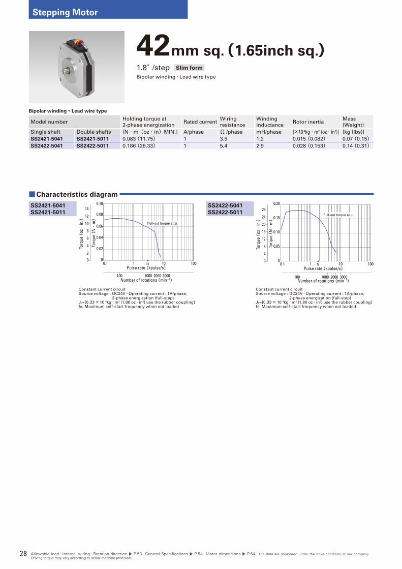
28
Stepping Motor
42mm sq.(1.65inch sq.)1.8°/step Slim form
Bipolar winding・Lead wire type
Bipolar winding・Lead wire type
Model numberHolding torque at
2-phase energizationRated current
Wiring
resistance
Winding
inductanceRotor inertia
Mass
(Weight)
Single shaft Double shafts [N・m(oz・in)MIN.] A/phase Ω /phase mH/phase [×10-4kg・m2 (oz・in2)] [kg (Ibs)]
SS2421-5041 SS2421-5011 0.083 (11.75) 1 3.5 1.2 0.015 (0.082) 0.07 (0.15)SS2422-5041 SS2422-5011 0.186 (26.33) 1 5.4 2.9 0.028 (0.153) 0.14 (0.31)
Constant current circuitSource voltage : DC24V・Operating current : 1A/phase, 2-phase energization (full-step)JL=[0.33× 10⁻⁴kg・m2 (1.80 oz・in2) use the rubber coupling]fs: Maximum self-start frequency when not loaded
Constant current circuitSource voltage : DC24V・Operating current : 1A/phase, 2-phase energization (full-step)JL=[0.33× 10⁻⁴kg・m2 (1.80 oz・in2) use the rubber coupling]fs: Maximum self-start frequency when not loaded
SS2422-5041
SS2422-5011
■Characteristics diagram
SS2421-5041
SS2421-5011
Pulse rate (kpulse/s)
Number of rotations (min-1)
fs0
Torq
ue (
oz・
in.)
14
12
10
8
6
4
2
Torq
ue (
N・
m)
0
0.02
0.04
0.06
0.08
0.10
0.1 1 10 100
2000 3000100 1000
Pull-out torque at JL
Torq
ue (
N・
m)
0
0.05
0.10
0.15
0.20
0.1 1 10 100
2000 3000100 1000
Pulse rate (kpulse/s)
Number of rotations (min-1)
fs0
Torq
ue (
oz・
in.)
24
28
20
16
12
4
8
Pull-out torque at JL
Allowable load・Internal wiring・Rotation direction P.53 General Specifications P.54 Motor dimensions P.64 The data are measured under the drive condition of our company. Driving torque may vary according to actual machine precision.
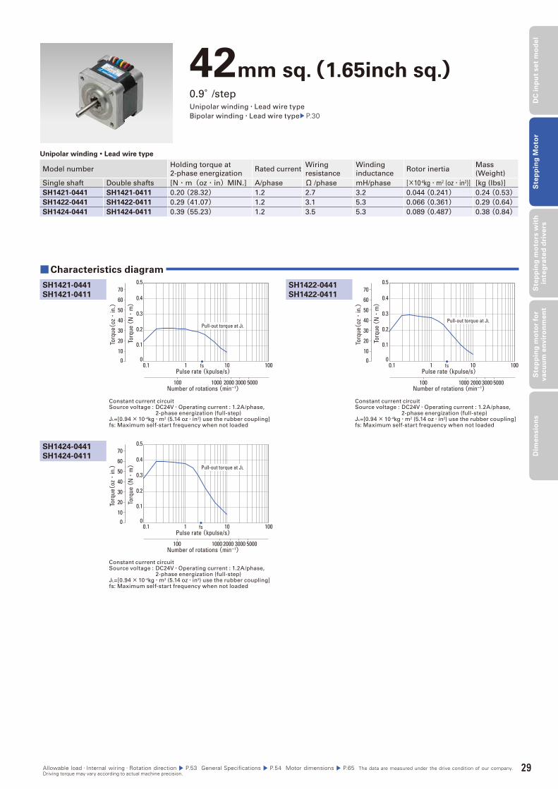
29
DC
in
pu
t se
t m
od
el
Ste
pp
ing
Mo
tor
Ste
pp
ing
mo
tors
wit
h
inte
gra
ted
dri
ve
rsS
tep
pin
g m
oto
r fo
r v
acu
um
en
vir
on
me
nt
Dim
en
sio
ns
42mm sq.(1.65inch sq.)0.9°/stepUnipolar winding・Lead wire type
Bipolar winding・Lead wire type P.30
Unipolar winding・Lead wire type
Model numberHolding torque at
2-phase energizationRated current
Wiring
resistance
Winding
inductanceRotor inertia
Mass
(Weight)
Single shaft Double shafts [N・m(oz・in)MIN.] A/phase Ω /phase mH/phase [×10-4kg・m2 (oz・in2)] [kg (Ibs)]
SH1421-0441 SH1421-0411 0.20 (28.32) 1.2 2.7 3.2 0.044 (0.241) 0.24 (0.53)SH1422-0441 SH1422-0411 0.29 (41.07) 1.2 3.1 5.3 0.066 (0.361) 0.29 (0.64)SH1424-0441 SH1424-0411 0.39 (55.23) 1.2 3.5 5.3 0.089 (0.487) 0.38 (0.84)
Constant current circuitSource voltage : DC24V・Operating current : 1.2A/phase, 2-phase energization (full-step)JL=[0.94× 10⁻⁴kg・m2 (5.14 oz・in2) use the rubber coupling]fs: Maximum self-start frequency when not loaded
Constant current circuitSource voltage : DC24V・Operating current : 1.2A/phase, 2-phase energization (full-step)JL=[0.94× 10⁻⁴kg・m2 (5.14 oz・in2) use the rubber coupling]fs: Maximum self-start frequency when not loaded
SH1422-0441
SH1422-0411
■Characteristics diagram
SH1421-0441
SH1421-0411
SH1424-0441
SH1424-0411
Constant current circuitSource voltage : DC24V・Operating current : 1.2A/phase, 2-phase energization (full-step)JL=[0.94× 10⁻⁴kg・m2 (5.14 oz・in2) use the rubber coupling]fs: Maximum self-start frequency when not loaded
Pulse rate (kpulse/s)
Number of rotations (min-1)
fs
Torq
ue (
N・
m)
0.1 1 10 100
1000 2000 3000 5000100
0.1
0.2
0.3
0.4
0.5
00
Torq
ue(oz・
in.)
70
60
50
40
30
20
10
Pull-out torque at JL
Pulse rate (kpulse/s)
Number of rotations (min-1)
fs
Torq
ue (
N・
m)
0.1 1 10 100
1000 2000 3000 5000100
0.1
0.2
0.3
0.4
0.5
00To
rque(
oz・
in.)
70
60
50
40
30
20
10
Pull-out torque at JL
Pulse rate (kpulse/s)
Number of rotations (min-1)
fs
Torq
ue (
N・
m)
0.1 1 10 100
1000 2000 3000 5000100
0.1
0.2
0.3
0.4
0.5
00
Torq
ue(oz・
in.)
70
60
50
40
30
20
10
Pull-out torque at JL
Allowable load・Internal wiring・Rotation direction P.53 General Specifications P.54 Motor dimensions P.65 The data are measured under the drive condition of our company. Driving torque may vary according to actual machine precision.
29
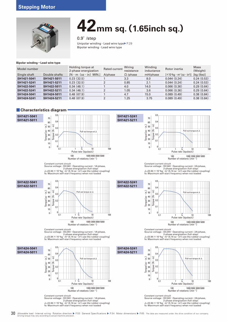
30
Stepping Motor
42mm sq.(1.65inch sq.)0.9°/stepUnipolar winding・Lead wire type P.29Bipolar winding・Lead wire type
Bipolar winding・Lead wire type
Model numberHolding torque at
2-phase energizationRated current
Wiring
resistance
Winding
inductanceRotor inertia
Mass
(Weight)
Single shaft Double shafts [N・m(oz・in)MIN.] A/phase Ω /phase mH/phase [×10-4kg・m2 (oz・in2)] [kg (Ibs)]
SH1421-5041 SH1421-5011 0.23 (32.5) 1 3.3 8.0 0.044 (0.24) 0.24 (0.53)SH1421-5241 SH1421-5211 0.23 (32.5) 2 0.85 2.1 0.044 (0.24) 0.24 (0.53)SH1422-5041 SH1422-5011 0.34 (48.1) 1 4.0 14.0 0.066 (0.36) 0.29 (0.64)SH1422-5241 SH1422-5211 0.34 (48.1) 2 1.05 3.6 0.066 (0.36) 0.29 (0.64)SH1424-5041 SH1424-5011 0.48 (67.9) 1 4.7 15.0 0.089 (0.49) 0.38 (0.84)SH1424-5241 SH1424-5211 0.48 (67.9) 2 1.25 3.75 0.089 (0.49) 0.38 (0.84)
Constant current circuitSource voltage : DC24V・Operating current : 1A/phase, 2-phase energization (full-step)JL=[0.94× 10⁻⁴kg・m2 (5.14 oz・in2) use the rubber coupling]fs: Maximum self-start frequency when not loaded
Constant current circuitSource voltage : DC24V・Operating current : 2A/phase, 2-phase energization (full-step)JL=[0.94× 10⁻⁴kg・m2 (5.14 oz・in2) use the rubber coupling]fs: Maximum self-start frequency when not loaded
SH1421-5241
SH1421-5211
■Characteristics diagram
SH1421-5041
SH1421-5011
SH1422-5041
SH1422-5011
SH1424-5041
SH1424-5011
SH1422-5241
SH1422-5211
SH1424-5241
SH1424-5211
Constant current circuitSource voltage : DC24V・Operating current : 1A/phase, 2-phase energization (full-step)JL=[0.94× 10⁻⁴kg・m2 (5.14 oz・in2) use the rubber coupling]fs: Maximum self-start frequency when not loaded
Constant current circuitSource voltage : DC24V・Operating current : 1A/phase, 2-phase energization (full-step)JL=[0.94× 10⁻⁴kg・m2 (5.14 oz・in2) use the rubber coupling]fs: Maximum self-start frequency when not loaded
Constant current circuitSource voltage : DC24V・Operating current : 2A/phase, 2-phase energization (full-step)JL=[0.94× 10⁻⁴kg・m2 (5.14 oz・in2) use the rubber coupling]fs: Maximum self-start frequency when not loaded
Constant current circuitSource voltage : DC24V・Operating current : 2A/phase, 2-phase energization (full-step)JL=[0.94× 10⁻⁴kg・m2 (5.14 oz・in2) use the rubber coupling]fs: Maximum self-start frequency when not loaded
Torq
ue (
N・
m)
0.1 1 10 100
0.5
0.4
0.3
0.2
0.1
0
1000 2000 3000 5000100
Pulse rate (kpulse/s)
Number of rotations (min-1)
fs0
Torq
ue(oz・
in.)
70
60
50
40
30
20
10
Pull-out torque at JL
Torq
ue (
N・
m)
0.1 1 10 100
0.1
0.2
0.3
0.4
0.5
0
Pulse rate (kpulse/s)
Number of rotations (min-1)
fs0
Torq
ue(oz・
in.)
70
60
50
40
30
20
10
1000 2000 3000 5000100
Pull-out torque at JL
Torq
ue (
N・
m)
0.1 1 10 100
0.5
0.4
0.3
0.2
0.1
0
1000 2000 3000 5000100
Pulse rate (kpulse/s)
Number of rotations (min-1)
fs0
Torq
ue(oz・
in.)
70
60
50
40
30
20
10
Pull-out torque at JL
Torq
ue (
N・
m)
0.1 1 10 100
0.5
0.4
0.3
0.2
0.1
0
1000 2000 3000 5000100
Pulse rate (kpulse/s)
Number of rotations (min-1)
fs0
Torq
ue(oz・
in.)
70
60
50
40
30
20
10
Pull-out torque at JL
Torq
ue (
N・
m)
0.1 1 10 100
0.1
0.2
0.3
0.4
0.5
0
Pulse rate (kpulse/s)
Number of rotations (min-1)
fs0
Torq
ue(oz・
in.)
70
60
50
40
30
20
10
1000 2000 3000 5000100
Pull-out torque at JL
Torq
ue (
N・
m)
0.1 1 10 100
0.1
0.2
0.3
0.4
0.5
0
Pulse rate (kpulse/s)
Number of rotations (min-1)
fs0
Torq
ue(oz・
in.)
70
60
50
40
30
20
10
10002000 3000 5000100
Pull-out torque at JL
Allowable load・Internal wiring・Rotation direction P.53 General Specifications P.54 Motor dimensions P.65 The data are measured under the drive condition of our company. Driving torque may vary according to actual machine precision.
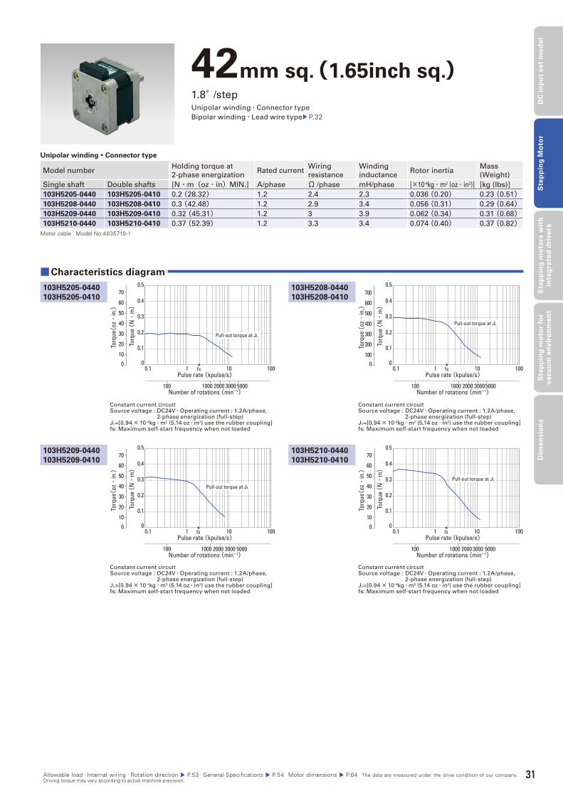
31
DC
in
pu
t se
t m
od
el
Ste
pp
ing
Mo
tor
Ste
pp
ing
mo
tors
wit
h
inte
gra
ted
dri
ve
rsS
tep
pin
g m
oto
r fo
r v
acu
um
en
vir
on
me
nt
Dim
en
sio
ns
42mm sq.(1.65inch sq.)1.8°/stepUnipolar winding・Connector type
Bipolar winding・Lead wire type P.32
Unipolar winding・Connector type
Model numberHolding torque at
2-phase energizationRated current
Wiring
resistance
Winding
inductanceRotor inertia
Mass
(Weight)
Single shaft Double shafts [N・m(oz・in)MIN.] A/phase Ω /phase mH/phase [×10-4kg・m2 (oz・in2)] [kg (Ibs)]
103H5205-0440 103H5205-0410 0.2 (28.32) 1.2 2.4 2.3 0.036 (0.20) 0.23 (0.51)103H5208-0440 103H5208-0410 0.3 (42.48) 1.2 2.9 3.4 0.056 (0.31) 0.29 (0.64)103H5209-0440 103H5209-0410 0.32 (45.31) 1.2 3 3.9 0.062 (0.34) 0.31 (0.68)103H5210-0440 103H5210-0410 0.37 (52.39) 1.2 3.3 3.4 0.074 (0.40) 0.37 (0.82)
Motor cable:Model No.4835710-1
Constant current circuitSource voltage : DC24V・Operating current : 1.2A/phase, 2-phase energization (full-step)JL=[0.94× 10⁻⁴kg・m2 (5.14 oz・in2) use the rubber coupling]fs: Maximum self-start frequency when not loaded
Constant current circuitSource voltage : DC24V・Operating current : 1.2A/phase, 2-phase energization (full-step)JL=[0.94× 10⁻⁴kg・m2 (5.14 oz・in2) use the rubber coupling]fs: Maximum self-start frequency when not loaded
103H5208-0440
103H5208-0410
■Characteristics diagram
103H5205-0440
103H5205-0410
103H5209-0440
103H5209-0410
103H5210-0440
103H5210-0410
Constant current circuitSource voltage : DC24V・Operating current : 1.2A/phase, 2-phase energization (full-step)JL=[0.94× 10⁻⁴kg・m2 (5.14 oz・in2) use the rubber coupling]fs: Maximum self-start frequency when not loaded
Constant current circuitSource voltage : DC24V・Operating current : 1.2A/phase, 2-phase energization (full-step)JL=[0.94× 10⁻⁴kg・m2 (5.14 oz・in2) use the rubber coupling]fs: Maximum self-start frequency when not loaded
Torq
ue (
N・
m)
Pulse rate (kpulse/s)
Number of rotations (min-1)
0.1 1 10 100
1000 2000 3000 5000100
fs
0.1
0.2
0.3
0.4
0.5
00
Torq
ue(oz・
in.)
70
60
50
40
30
20
10
Pull-out torque at JL
Torq
ue (
N・
m)
Pulse rate (kpulse/s)
Number of rotations (min-1)
0.1 1 10 100
1000 2000 30005000100
fs
0.1
0.2
0.3
0.4
0.5
00To
rque
(oz・
in.)
700
600
500
400
300
200
100
Pull-out torque at JL
Torq
ue (
N・
m)
Pulse rate (kpulse/s)
Number of rotations (min-1)
0.1 1 10 100
1000 2000 3000 5000100
fs
0.1
0.2
0.3
0.4
0.5
00
Torq
ue(oz・
in.)
70
60
50
40
30
20
10
Pull-out torque at JL
Torq
ue (
N・
m)
Pulse rate (kpulse/s)
Number of rotations (min-1)
0.1 1 10 100
1000 2000 3000 5000100
fs
0.1
0.2
0.3
0.4
0.5
00
Torq
ue(oz・
in.)
70
60
50
40
30
20
10
Pull-out torque at JL
Allowable load・Internal wiring・Rotation direction P.53 General Specifications P.54 Motor dimensions P.64 The data are measured under the drive condition of our company. Driving torque may vary according to actual machine precision.
31
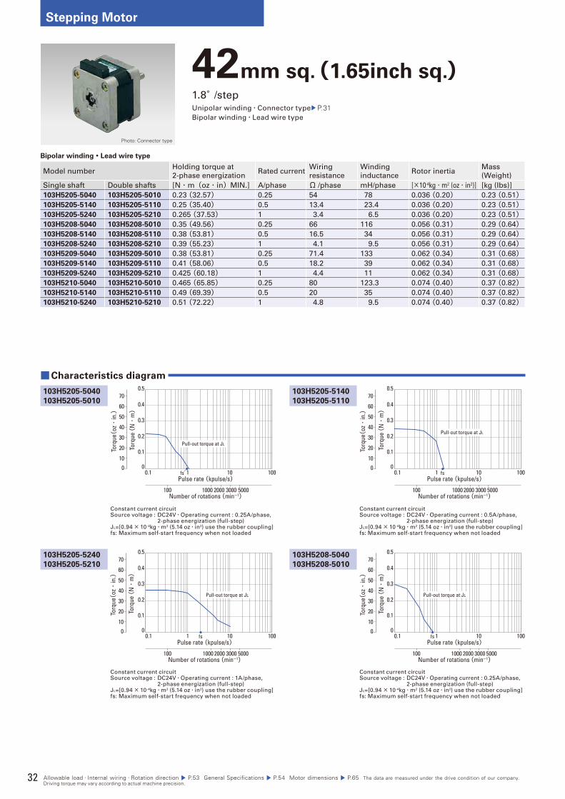
32
Stepping Motor
42mm sq.(1.65inch sq.)1.8°/stepUnipolar winding・Connector type P.31Bipolar winding・Lead wire type
Bipolar winding・Lead wire type
Model numberHolding torque at
2-phase energizationRated current
Wiring
resistance
Winding
inductanceRotor inertia
Mass
(Weight)
Single shaft Double shafts [N・m(oz・in)MIN.] A/phase Ω /phase mH/phase [×10-4kg・m2 (oz・in2)] [kg (Ibs)]
103H5205-5040 103H5205-5010 0.23 (32.57) 0.25 54 78 0.036 (0.20) 0.23 (0.51)103H5205-5140 103H5205-5110 0.25 (35.40) 0.5 13.4 23.4 0.036 (0.20) 0.23 (0.51)103H5205-5240 103H5205-5210 0.265 (37.53) 1 3.4 6.5 0.036 (0.20) 0.23 (0.51)103H5208-5040 103H5208-5010 0.35 (49.56) 0.25 66 116 0.056 (0.31) 0.29 (0.64)103H5208-5140 103H5208-5110 0.38 (53.81) 0.5 16.5 34 0.056 (0.31) 0.29 (0.64)103H5208-5240 103H5208-5210 0.39 (55.23) 1 4.1 9.5 0.056 (0.31) 0.29 (0.64)103H5209-5040 103H5209-5010 0.38 (53.81) 0.25 71.4 133 0.062 (0.34) 0.31 (0.68)103H5209-5140 103H5209-5110 0.41 (58.06) 0.5 18.2 39 0.062 (0.34) 0.31 (0.68)103H5209-5240 103H5209-5210 0.425 (60.18) 1 4.4 11 0.062 (0.34) 0.31 (0.68)103H5210-5040 103H5210-5010 0.465 (65.85) 0.25 80 123.3 0.074 (0.40) 0.37 (0.82)103H5210-5140 103H5210-5110 0.49 (69.39) 0.5 20 35 0.074 (0.40) 0.37 (0.82)103H5210-5240 103H5210-5210 0.51 (72.22) 1 4.8 9.5 0.074 (0.40) 0.37 (0.82)
Constant current circuitSource voltage : DC24V・Operating current : 0.25A/phase, 2-phase energization (full-step)JL=[0.94× 10⁻⁴kg・m2 (5.14 oz・in2) use the rubber coupling]fs: Maximum self-start frequency when not loaded
Constant current circuitSource voltage : DC24V・Operating current : 0.5A/phase, 2-phase energization (full-step)JL=[0.94× 10⁻⁴kg・m2 (5.14 oz・in2) use the rubber coupling]fs: Maximum self-start frequency when not loaded
103H5205-5140
103H5205-5110
■Characteristics diagram
103H5205-5040
103H5205-5010
103H5205-5240
103H5205-5210
103H5208-5040
103H5208-5010
Constant current circuitSource voltage : DC24V・Operating current : 1A/phase, 2-phase energization (full-step)JL=[0.94× 10⁻⁴kg・m2 (5.14 oz・in2) use the rubber coupling]fs: Maximum self-start frequency when not loaded
Constant current circuitSource voltage : DC24V・Operating current : 0.25A/phase, 2-phase energization (full-step)JL=[0.94× 10⁻⁴kg・m2 (5.14 oz・in2) use the rubber coupling]fs: Maximum self-start frequency when not loaded
Torq
ue (
N・
m)
0.1 1 10 100
1000 2000 3000 5000100
0.1
0.2
0.3
0.4
0.5
0
Pulse rate (kpulse/s)
Number of rotations (min-1)
fs0
Torq
ue(oz・
in.)
70
60
50
40
30
20
10
Pull-out torque at JL
Torq
ue (
N・
m)
0.1 1 10 100
1000 2000 3000 5000100
0.1
0.2
0.3
0.4
0.5
0
Pulse rate (kpulse/s)
Number of rotations (min-1)
fs0
Torq
ue(oz・
in.)
70
60
50
40
30
20
10
Pull-out torque at JL
Torq
ue (
N・
m)
0.1 1 10 100
1000 2000 3000 5000100
0.1
0.2
0.3
0.4
0.5
0
Pulse rate (kpulse/s)
Number of rotations (min-1)
fs0
Torq
ue(oz・
in.)
70
60
50
40
30
20
10
Pull-out torque at JL
Torq
ue (
N・
m)
0.1 1 10 100
1000 2000 3000 5000100
0.1
0.2
0.3
0.4
0.5
0
Pulse rate (kpulse/s)
Number of rotations (min-1)
fs0
Torq
ue(oz・
in.)
70
60
50
40
30
20
10
Pull-out torque at JL
Allowable load・Internal wiring・Rotation direction P.53 General Specifications P.54 Motor dimensions P.65 The data are measured under the drive condition of our company. Driving torque may vary according to actual machine precision.
Photo: Connector type

33
DC
in
pu
t se
t m
od
el
Ste
pp
ing
Mo
tor
Ste
pp
ing
mo
tors
wit
h
inte
gra
ted
dri
ve
rsS
tep
pin
g m
oto
r fo
r v
acu
um
en
vir
on
me
nt
Dim
en
sio
ns
Constant current circuitSource voltage : DC24V・Operating current : 0.25A/phase, 2-phase energization (full-step)JL=[0.94× 10⁻⁴kg・m2 (5.14 oz・in2) use the rubber coupling]fs: Maximum self-start frequency when not loaded
Constant current circuitSource voltage : DC24V・Operating current : 0.5A/phase, 2-phase energization (full-step)JL=[0.94× 10⁻⁴kg・m2 (5.14 oz・in2) use the rubber coupling]fs: Maximum self-start frequency when not loaded
Constant current circuitSource voltage : DC24V・Operating current : 0.5A/phase, 2-phase energization (full-step)JL=[0.94× 10⁻⁴kg・m2 (5.14 oz・in2) use the rubber coupling]fs: Maximum self-start frequency when not loaded
Constant current circuitSource voltage : DC24V・Operating current : 1A/phase, 2-phase energization (full-step)JL=[0.94× 10⁻⁴kg・m2 (5.14 oz・in2) use the rubber coupling]fs: Maximum self-start frequency when not loaded
103H5209-5140
103H5209-5110
103H5208-5240
103H5208-5210
■ Characteristics diagram
103H5209-5040
103H5209-5010
103H5208-5140
103H5208-5110
103H5209-5240
103H5209-5210
103H5210-5140
103H5210-5110
103H5210-5040
103H5210-5010
103H5210-5240
103H5210-5210
Constant current circuitSource voltage : DC24V・Operating current : 1A/phase, 2-phase energization (full-step)JL=[0.94× 10⁻⁴kg・m2 (5.14 oz・in2) use the rubber coupling]fs: Maximum self-start frequency when not loaded
Constant current circuitSource voltage : DC24V・Operating current : 0.5A/phase, 2-phase energization (full-step)JL=[0.94× 10⁻⁴kg・m2 (5.14 oz・in2) use the rubber coupling]fs: Maximum self-start frequency when not loaded
Constant current circuitSource voltage : DC24V・Operating current : 0.25A/phase, 2-phase energization (full-step)JL=[0.94× 10⁻⁴kg・m2 (5.14 oz・in2) use the rubber coupling]fs: Maximum self-start frequency when not loaded
Constant current circuitSource voltage : DC24V・Operating current : 1A/phase, 2-phase energization (full-step)JL=[0.94× 10⁻⁴kg・m2 (5.14 oz・in2) use the rubber coupling]fs: Maximum self-start frequency when not loaded
Torq
ue (
N・
m)
0.1 1 10 100
1000 2000 3000 5000100
0.1
0.2
0.3
0.4
0.5
0
Pulse rate (kpulse/s)
Number of rotations (min-1)
fs0
Torq
ue(oz・
in.)
70
60
50
40
30
20
10
Pull-out torque at JL
Torq
ue (
N・
m)
0.1 1 10 100
1000 2000 3000 5000100
0.1
0.2
0.3
0.4
0.5
0
Pulse rate (kpulse/s)
Number of rotations (min-1)
fs0
Torq
ue(oz・
in.)
70
60
50
40
30
20
10
Pull-out torque at JL
Torq
ue (
N・
m)
0.1 1 10 100
1000 2000 3000 5000100
0.1
0.2
0.3
0.4
0.5
0
Pulse rate (kpulse/s)
Number of rotations (min-1)
fs0
Torq
ue(oz・
in.)
70
60
50
40
30
20
10
Pull-out torque at JL
Torq
ue (
N・
m)
0.1 1 10 100
1000 2000 3000 5000100
0.1
0.2
0.3
0.4
0.5
0
Pulse rate (kpulse/s)
Number of rotations (min-1)
fs0
Torq
ue(oz・
in.)
70
60
50
40
30
20
10
Pull-out torque at JL
Torq
ue (
N・
m)
0.1 1 10 100
1000 2000 3000 5000100
0.1
0.2
0.3
0.4
0.5
0
Pulse rate (kpulse/s)
Number of rotations (min-1)
fs0
Torq
ue(oz・
in.)
70
60
50
40
30
20
10
Pull-out torque at JL
Torq
ue (
N・
m)
0.1 1 10 100
1000 2000 3000 5000100
0.1
0.2
0.3
0.4
0.5
0
Pulse rate (kpulse/s)
Number of rotations (min-1)
fs0
Torq
ue(oz・
in.)
70
60
50
40
30
20
10
Pull-out torque at JL
Torq
ue (
N・
m)
0.1 1 10 100
1000 2000 3000 5000100
0.1
0.2
0.3
0.4
0.5
0
Pulse rate (kpulse/s)
Number of rotations (min-1)
fs0
Torq
ue(oz・
in.)
70
60
50
40
30
20
10
Pull-out torque at JL
Torq
ue (
N・
m)
0.1 1 10 100
1000 2000 30005000100
0.1
0.2
0.3
0.4
0.5
0
Pulse rate (kpulse/s)
Number of rotations (min-1)
fs0
Torq
ue(oz・
in.)
70
60
50
40
30
20
10
Pull-out torque at JL
Allowable load・Internal wiring・Rotation direction P.53 General Specifications P.54 Motor dimensions P.65 The data are measured under the drive condition of our company. Driving torque may vary according to actual machine precision.
33
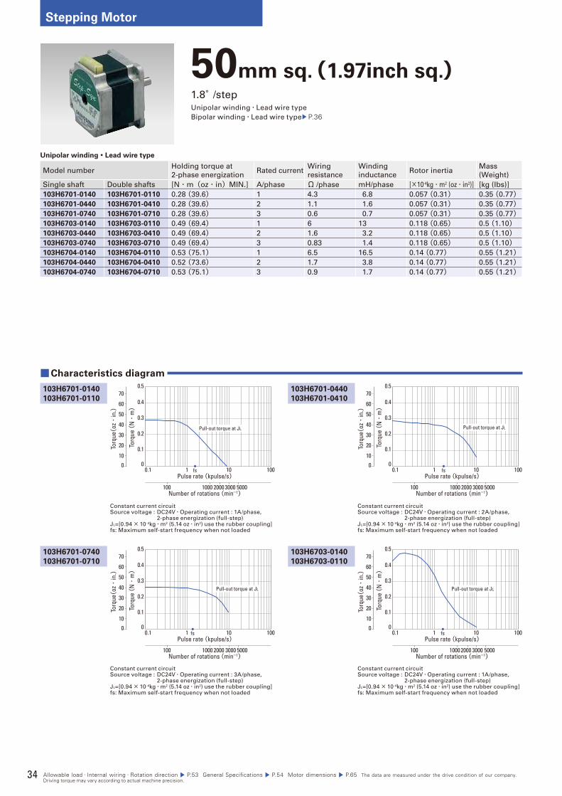
34
Stepping Motor
50mm sq.(1.97inch sq.)1.8°/stepUnipolar winding・Lead wire type
Bipolar winding・Lead wire type P.36
Unipolar winding・Lead wire type
Model numberHolding torque at
2-phase energizationRated current
Wiring
resistance
Winding
inductanceRotor inertia
Mass
(Weight)
Single shaft Double shafts [N・m(oz・in)MIN.] A/phase Ω /phase mH/phase [×10-4kg・m2 (oz・in2)] [kg (Ibs)]
103H6701-0140 103H6701-0110 0.28 (39.6) 1 4.3 6.8 0.057 (0.31) 0.35 (0.77)103H6701-0440 103H6701-0410 0.28 (39.6) 2 1.1 1.6 0.057 (0.31) 0.35 (0.77)103H6701-0740 103H6701-0710 0.28 (39.6) 3 0.6 0.7 0.057 (0.31) 0.35 (0.77)103H6703-0140 103H6703-0110 0.49 (69.4) 1 6 13 0.118 (0.65) 0.5 (1.10)103H6703-0440 103H6703-0410 0.49 (69.4) 2 1.6 3.2 0.118 (0.65) 0.5 (1.10)103H6703-0740 103H6703-0710 0.49 (69.4) 3 0.83 1.4 0.118 (0.65) 0.5 (1.10)103H6704-0140 103H6704-0110 0.53 (75.1) 1 6.5 16.5 0.14 (0.77) 0.55 (1.21)103H6704-0440 103H6704-0410 0.52 (73.6) 2 1.7 3.8 0.14 (0.77) 0.55 (1.21)103H6704-0740 103H6704-0710 0.53 (75.1) 3 0.9 1.7 0.14 (0.77) 0.55 (1.21)
Constant current circuitSource voltage : DC24V・Operating current : 1A/phase, 2-phase energization (full-step)JL=[0.94× 10⁻⁴kg・m2 (5.14 oz・in2) use the rubber coupling]fs: Maximum self-start frequency when not loaded
Constant current circuitSource voltage : DC24V・Operating current : 2A/phase, 2-phase energization (full-step)JL=[0.94× 10⁻⁴kg・m2 (5.14 oz・in2) use the rubber coupling]fs: Maximum self-start frequency when not loaded
103H6701-0440
103H6701-0410
■Characteristics diagram
103H6701-0140
103H6701-0110
103H6701-0740
103H6701-0710
103H6703-0140
103H6703-0110
Constant current circuitSource voltage : DC24V・Operating current : 3A/phase, 2-phase energization (full-step)JL=[0.94× 10⁻⁴kg・m2 (5.14 oz・in2) use the rubber coupling]fs: Maximum self-start frequency when not loaded
Constant current circuitSource voltage : DC24V・Operating current : 1A/phase, 2-phase energization (full-step)JL=[0.94× 10⁻⁴kg・m2 (5.14 oz・in2) use the rubber coupling]fs: Maximum self-start frequency when not loaded
Torq
ue (
N・
m)
Pulse rate (kpulse/s)
Number of rotations (min-1)
0.1 1 10 100
1000 2000 3000 5000100
fs
0.1
0.2
0.3
0.4
0.5
00
Torq
ue(oz・
in.)
70
60
50
40
30
20
10
Pull-out torque at JL
Torq
ue (
N・
m)
Pulse rate (kpulse/s)
Number of rotations (min-1)
0.1 1 10 100
1000 2000 3000 5000100
fs
0.1
0.2
0.3
0.4
0.5
00
Torq
ue(oz・
in.)
70
60
50
40
30
20
10
Pull-out torque at JL
Torq
ue (
N・
m)
Pulse rate (kpulse/s)
Number of rotations (min-1)
0.1 1 10 100
1000 2000 3000 5000100
fs
0.1
0.2
0.3
0.4
0.5
00
Torq
ue(oz・
in.)
70
60
50
40
30
20
10
Pull-out torque at JL
Torq
ue (
N・
m)
Pulse rate (kpulse/s)
Number of rotations (min-1)
0.1 1 10 100
1000 2000 3000 5000100
fs
0.1
0.2
0.3
0.4
0.5
00
Torq
ue(oz・
in.)
70
60
50
40
30
20
10
Pull-out torque at JL
Allowable load・Internal wiring・Rotation direction P.53 General Specifications P.54 Motor dimensions P.65 The data are measured under the drive condition of our company. Driving torque may vary according to actual machine precision.
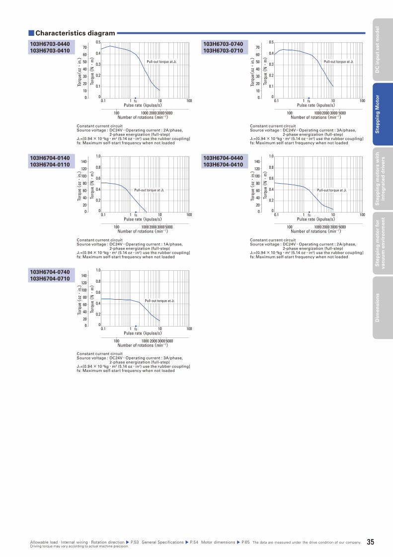
35
DC
in
pu
t se
t m
od
el
Ste
pp
ing
Mo
tor
Ste
pp
ing
mo
tors
wit
h
inte
gra
ted
dri
ve
rsS
tep
pin
g m
oto
r fo
r v
acu
um
en
vir
on
me
nt
Dim
en
sio
ns
Constant current circuitSource voltage : DC24V・Operating current : 1A/phase, 2-phase energization (full-step)JL=[0.94× 10⁻⁴kg・m2 (5.14 oz・in2) use the rubber coupling]fs: Maximum self-start frequency when not loaded
Constant current circuitSource voltage : DC24V・Operating current : 2A/phase, 2-phase energization (full-step)JL=[0.94× 10⁻⁴kg・m2 (5.14 oz・in2) use the rubber coupling]fs: Maximum self-start frequency when not loaded
Constant current circuitSource voltage : DC24V・Operating current : 2A/phase, 2-phase energization (full-step)JL=[0.94× 10⁻⁴kg・m2 (5.14 oz・in2) use the rubber coupling]fs: Maximum self-start frequency when not loaded
Constant current circuitSource voltage : DC24V・Operating current : 3A/phase, 2-phase energization (full-step)JL=[0.94× 10⁻⁴kg・m2 (5.14 oz・in2) use the rubber coupling]fs: Maximum self-start frequency when not loaded
103H6704-0440
103H6704-0410
103H6703-0740
103H6703-0710
■Characteristics diagram
103H6704-0140
103H6704-0110
103H6703-0440
103H6703-0410
103H6704-0740
103H6704-0710
Constant current circuitSource voltage : DC24V・Operating current : 3A/phase, 2-phase energization (full-step)JL=[0.94× 10⁻⁴kg・m2 (5.14 oz・in2) use the rubber coupling]fs: Maximum self-start frequency when not loaded
Torq
ue (
N・
m)
Pulse rate (kpulse/s)
Number of rotations (min-1)
0.1 1 10 100
1000 2000 3000 5000100
fs
0.2
0.4
0.6
0.8
1.0
00
Torq
ue (
oz・
in.)
140
120
100
80
60
40
20
Pull-out torque at JL
Torq
ue (
N・
m)
Pulse rate (kpulse/s)
Number of rotations (min-1)
0.1 1 10 100
1000 2000 3000 5000100
fs
0.1
0.2
0.3
0.4
0.5
00
Torq
ue(oz・
in.)
70
60
50
40
30
20
10
Pull-out torque at JL
Torq
ue (
N・
m)
Pulse rate (kpulse/s)
Number of rotations (min-1)
0.1 1 10 100
1000 2000 3000 5000100
fs
0.2
0.4
0.6
0.8
1.0
00
Torq
ue (
oz・
in.)
140
120
100
80
60
40
20
Pull-out torque at JL
Torq
ue (
N・
m)
Pulse rate (kpulse/s)
Number of rotations (min-1)
0.1 1 10 100
1000 2000 3000 5000100
fs
0.1
0.2
0.3
0.4
0.5
00
Torq
ue(oz・
in.)
70
60
50
40
30
20
10
Pull-out torque at JL
Torq
ue (
N・
m)
Pulse rate (kpulse/s)
Number of rotations (min-1)
0.1 1 10 100
1000 2000 30005000100
fs
0.2
0.4
0.6
0.8
1.0
00
Torq
ue (
oz・
in.)
140
120
100
80
60
40
20
Pull-out torque at JL
Allowable load・Internal wiring・Rotation direction P.53 General Specifications P.54 Motor dimensions P.65 The data are measured under the drive condition of our company. Driving torque may vary according to actual machine precision.
35
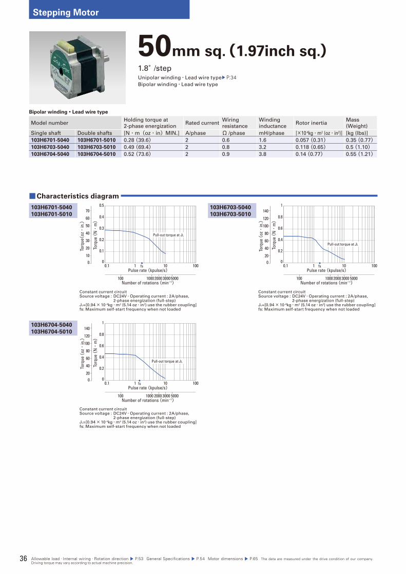
36
Stepping Motor
50mm sq.(1.97inch sq.)1.8°/stepUnipolar winding・Lead wire type P.34Bipolar winding・Lead wire type
Bipolar winding・Lead wire type
Model numberHolding torque at
2-phase energizationRated current
Wiring
resistance
Winding
inductanceRotor inertia
Mass
(Weight)
Single shaft Double shafts [N・m(oz・in)MIN.] A/phase Ω /phase mH/phase [×10-4kg・m2 (oz・in2)] [kg (Ibs)]
103H6701-5040 103H6701-5010 0.28 (39.6) 2 0.6 1.6 0.057 (0.31) 0.35 (0.77)103H6703-5040 103H6703-5010 0.49 (69.4) 2 0.8 3.2 0.118 (0.65) 0.5 (1.10)103H6704-5040 103H6704-5010 0.52 (73.6) 2 0.9 3.8 0.14 (0.77) 0.55 (1.21)
Constant current circuitSource voltage : DC24V・Operating current : 2A/phase, 2-phase energization (full-step)JL=[0.94× 10⁻⁴kg・m2 (5.14 oz・in2) use the rubber coupling]fs: Maximum self-start frequency when not loaded
Constant current circuitSource voltage : DC24V・Operating current : 2A/phase, 2-phase energization (full-step)JL=[0.94× 10⁻⁴kg・m2 (5.14 oz・in2) use the rubber coupling]fs: Maximum self-start frequency when not loaded
103H6703-5040
103H6703-5010
■Characteristics diagram
103H6701-5040
103H6701-5010
103H6704-5040
103H6704-5010
Constant current circuitSource voltage : DC24V・Operating current : 2A/phase, 2-phase energization (full-step)JL=[0.94× 10⁻⁴kg・m2 (5.14 oz・in2) use the rubber coupling]fs: Maximum self-start frequency when not loaded
Torq
ue (
N・
m)
Pulse rate (kpulse/s)
Number of rotations (min-1)
0.1 1 10 100
1000 2000 30005000100
fs
0.1
0.2
0.3
0.4
0.5
00
Torq
ue(oz・
in.)
70
60
50
40
30
20
10
Pull-out torque at JL
Torq
ue (
N・
m)
Pulse rate (kpulse/s)
Number of rotations (min-1)
0.1 1 10 100
1000 2000 3000 5000100
fs
0.2
0.4
0.6
0.8
1
00To
rque
(oz・
in.)
140
120
100
80
60
40
20
Pull-out torque at JL
Torq
ue (
N・
m)
Pulse rate (kpulse/s)
Number of rotations (min-1)
0.1 1 10 100
1000 2000 3000 5000100
fs
0.2
0.4
0.6
0.8
1
00
Torq
ue (
oz・
in.)
140
120
100
80
60
40
20
Pull-out torque at JL
Allowable load・Internal wiring・Rotation direction P.53 General Specifications P.54 Motor dimensions P.65 The data are measured under the drive condition of our company. Driving torque may vary according to actual machine precision.
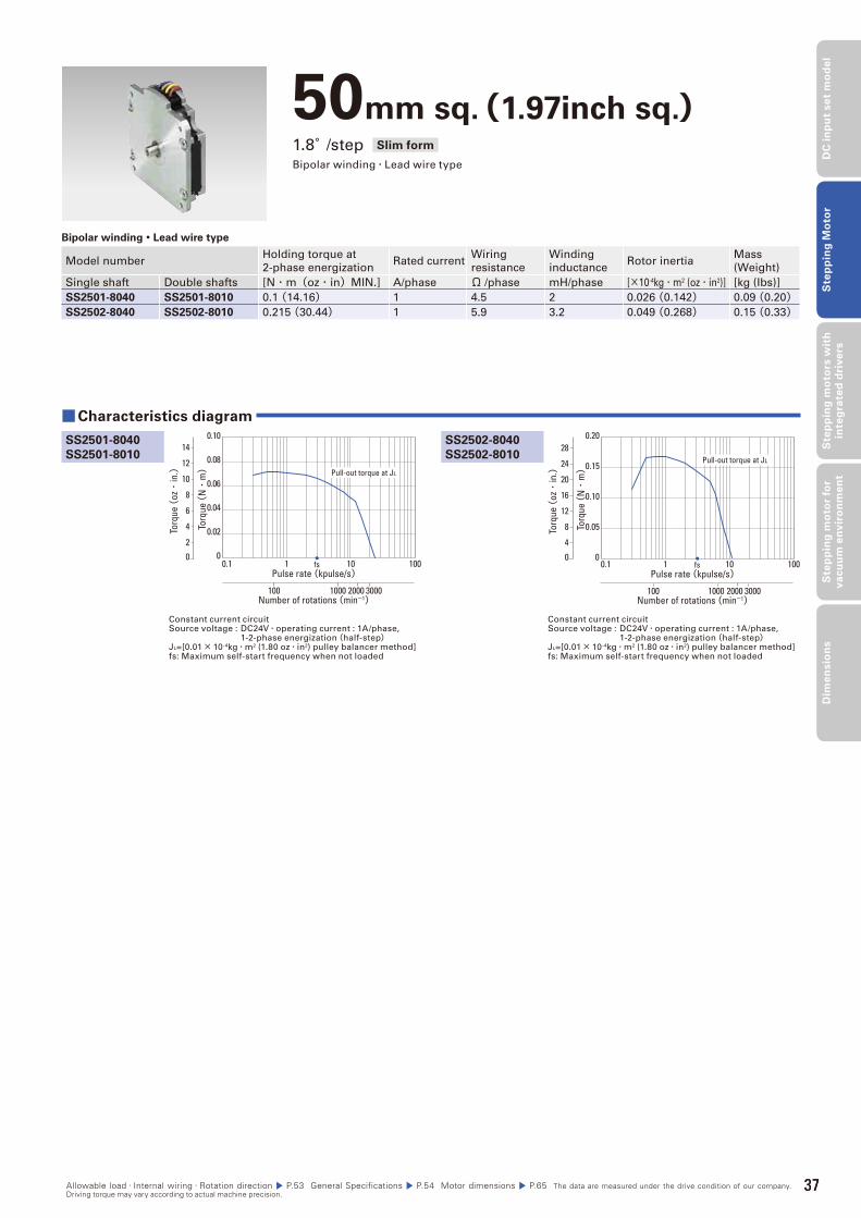
37
DC
in
pu
t se
t m
od
el
Ste
pp
ing
Mo
tor
Ste
pp
ing
mo
tors
wit
h
inte
gra
ted
dri
ve
rsS
tep
pin
g m
oto
r fo
r v
acu
um
en
vir
on
me
nt
Dim
en
sio
ns
50mm sq.(1.97inch sq.)1.8°/step Slim form
Bipolar winding・Lead wire type
Bipolar winding・Lead wire type
Model numberHolding torque at
2-phase energizationRated current
Wiring
resistance
Winding
inductanceRotor inertia
Mass
(Weight)
Single shaft Double shafts [N・m(oz・in)MIN.] A/phase Ω /phase mH/phase [×10-4kg・m2 (oz・in2)] [kg (Ibs)]
SS2501-8040 SS2501-8010 0.1 (14.16) 1 4.5 2 0.026 (0.142) 0.09 (0.20)SS2502-8040 SS2502-8010 0.215 (30.44) 1 5.9 3.2 0.049 (0.268) 0.15 (0.33)
Constant current circuitSource voltage : DC24V・operating current : 1A/phase, 1-2-phase energization(half-step)JL=[0.01× 10⁻⁴kg・m2 (1.80 oz・in2) pulley balancer method]fs: Maximum self-start frequency when not loaded
Constant current circuitSource voltage : DC24V・operating current : 1A/phase, 1-2-phase energization(half-step)JL=[0.01× 10⁻⁴kg・m2 (1.80 oz・in2) pulley balancer method]fs: Maximum self-start frequency when not loaded
SS2502-8040
SS2502-8010
■Characteristics diagram
SS2501-8040
SS2501-8010
Torq
ue (
N・
m)
0
0.02
0.04
0.06
0.08
0.10
0.1 1 10 100
2000 3000100 1000
Pulse rate (kpulse/s)
Number of rotations (min-1)
fs0
Torq
ue (
oz・
in.)
14
12
10
8
6
4
2
Pull-out torque at JL
Torq
ue (
N・
m)
0
0.05
0.10
0.15
0.20
0.1 1 10 100
2000 3000100 1000
Pulse rate (kpulse/s)
Number of rotations (min-1)
fs0
Torq
ue (
oz・
in.)
24
28
20
16
12
4
8
Pull-out torque at JL
Allowable load・Internal wiring・Rotation direction P.53 General Specifications P.54 Motor dimensions P.65 The data are measured under the drive condition of our company. Driving torque may vary according to actual machine precision.
37

38
Stepping Motor
56mm sq.(2.20inch sq.)1.8°/stepUnipolar winding・Lead wire type
Bipolar winding・Lead wire type P.40
Unipolar winding・Lead wire type
Model numberHolding torque at
2-phase energizationRated current
Wiring
resistance
Winding
inductanceRotor inertia
Mass
(Weight)
Single shaft Double shafts [N・m(oz・in)MIN.] A/phase Ω /phase mH/phase [×10-4kg・m2 (oz・in2)] [kg (Ibs)]
103H7121-0140 103H7121-0110 0.39 (55.2) 1 4.8 8 0.1 (0.55) 0.47 (1.04)103H7121-0440 103H7121-0410 0.39 (55.2) 2 1.25 1.9 0.1 (0.55) 0.47 (1.04)103H7121-0740 103H7121-0710 0.39 (55.2) 3 0.6 0.8 0.1 (0.55) 0.47 (1.04)103H7123-0140 103H7123-0110 0.83 (117.) 1 6.7 15 0.21 (1.15) 0.65 (1.43)103H7123-0440 103H7123-0410 0.83 (117.5) 2 1.6 3.8 0.21 (1.15) 0.65 (1.43)103H7123-0740 103H7123-0710 0.78 (110.5) 3 0.77 1.58 0.21 (1.15) 0.65 (1.43)103H7124-0140 103H7124-0110 0.98 (138.8) 1 7 14.5 0.245 (1.34) 0.8 (1.76)103H7124-0440 103H7124-0410 0.98 (138.8) 2 1.7 3.1 0.245 (1.34) 0.8 (1.76)103H7124-0740 103H7124-0710 0.98 (138.8) 3 0.74 1.4 0.245 (1.34) 0.8 (1.76)103H7126-0140 103H7126-0110 1.27 (179.8) 1 8.6 19 0.36 (1.97) 0.98 (2.16)103H7126-0440 103H7126-0410 1.27 (179.8) 2 2 4.5 0.36 (1.97) 0.98 (2.16)103H7126-0740 103H7126-0710 1.27 (179.8) 3 0.9 2.2 0.36 (1.97) 0.98 (2.16)
Constant current circuitSource voltage : DC24V・Operating current : 1A/phase, 2-phase energization (full-step)JL=[0.94× 10⁻⁴kg・m2 (5.14 oz・in2) use the rubber coupling]fs: Maximum self-start frequency when not loaded
Constant current circuitSource voltage : DC24V・Operating current : 2A/phase, 2-phase energization (full-step)JL=[0.94× 10⁻⁴kg・m2 (5.14 oz・in2) use the rubber coupling]fs: Maximum self-start frequency when not loaded
103H7121-0440
103H7121-0410
■Characteristics diagram
103H7121-0140
103H7121-0110
103H7121-0740
103H7121-0710
103H7123-0140
103H7123-0110
Constant current circuitSource voltage : DC24V・Operating current : 3A/phase, 2-phase energization (full-step)JL=[0.94× 10⁻⁴kg・m2 (5.14 oz・in2) use the rubber coupling]fs: Maximum self-start frequency when not loaded
Constant current circuitSource voltage : DC24V・Operating current : 1A/phase, 2-phase energization (full-step)JL=[0.94× 10⁻⁴kg・m2 (5.14 oz・in2) use the rubber coupling]fs: Maximum self-start frequency when not loaded
Torq
ue (
N・
m)
Pulse rate (kpulse/s)
Number of rotations (min-1)
0.1 1 10 100
1000 2000 3000 5000100
fs
0.1
0.2
0.3
0.4
0.5
00
Torq
ue(oz・
in.)
70
60
50
40
30
20
10
Pull-out torque at JL
Torq
ue (
N・
m)
Pulse rate (kpulse/s)
Number of rotations (min-1)
0.1 1 10 100
1000 2000 3000 5000100
fs
0.1
0.2
0.3
0.4
0.5
00
Torq
ue(oz・
in.)
70
60
50
40
30
20
10
Pull-out torque at JL
Torq
ue (
N・
m)
Pulse rate (kpulse/s)
Number of rotations (min-1)
0.1 1 10 100
1000 2000 3000 5000100
fs
0.1
0.2
0.3
0.4
0.5
00
Torq
ue(oz・
in.)
70
60
50
40
30
20
10
Pull-out torque at JL
Torq
ue (
N・
m)
Pulse rate (kpulse/s)
Number of rotations (min-1)
0.1 1 10 100
1000 2000 3000 5000100
fs
0.2
0.4
0.6
0.8
1.0
00
Torq
ue (
oz・
in.)
140
120
100
80
60
40
20
Pull-out torque at JL
Allowable load・Internal wiring・Rotation direction P.53 General Specifications P.54 Motor dimensions P.66 The data are measured under the drive condition of our company. Driving torque may vary according to actual machine precision.

39
DC
in
pu
t se
t m
od
el
Ste
pp
ing
Mo
tor
Ste
pp
ing
mo
tors
wit
h
inte
gra
ted
dri
ve
rsS
tep
pin
g m
oto
r fo
r v
acu
um
en
vir
on
me
nt
Dim
en
sio
ns
Constant current circuitSource voltage : DC24V・Operating current : 1A/phase, 2-phase energization (full-step)JL=[2.6× 10⁻⁴kg・m2 (14.22 oz・in2) use the rubber coupling]fs: Maximum self-start frequency when not loaded
Constant current circuitSource voltage : DC24V・Operating current : 2A/phase, 2-phase energization (full-step)JL=[0.94× 10⁻⁴kg・m2 (5.14 oz・in2) use the rubber coupling]fs: Maximum self-start frequency when not loaded
Constant current circuitSource voltage : DC24V・Operating current : 2A/phase, 2-phase energization (full-step)JL=[2.6× 10⁻⁴kg・m2 (14.22 oz・in2) use the rubber coupling]fs: Maximum self-start frequency when not loaded
Constant current circuitSource voltage : DC24V・Operating current : 3A/phase, 2-phase energization (full-step)JL=[0.94× 10⁻⁴kg・m2 (5.14 oz・in2) use the rubber coupling]fs: Maximum self-start frequency when not loaded
103H7124-0440
103H7124-0410
103H7123-0740
103H7123-0710
■Characteristics diagram
103H7124-0140
103H7124-0110
103H7123-0440
103H7123-0410
103H7124-0740
103H7124-0710
103H7126-0440
103H7126-0410
103H7126-0140
103H7126-0110
103H7126-0740
103H7126-0710
Constant current circuitSource voltage : DC24V・Operating current : 3A/phase, 2-phase energization (full-step)JL=[2.6× 10⁻⁴kg・m2 (14.22 oz・in2) use the rubber coupling]fs: Maximum self-start frequency when not loaded
Constant current circuitSource voltage : DC24V・Operating current : 2A/phase, 2-phase energization (full-step)JL=[2.6× 10⁻⁴kg・m2 (14.22 oz・in2) use the rubber coupling]fs: Maximum self-start frequency when not loaded
Constant current circuitSource voltage : DC24V・Operating current : 1A/phase, 2-phase energization (full-step)JL=[2.6× 10⁻⁴kg・m2 (14.22 oz・in2) use the rubber coupling]fs: Maximum self-start frequency when not loaded
Constant current circuitSource voltage : DC24V・Operating current : 3A/phase, 2-phase energization (full-step)JL=[2.6× 10⁻⁴kg・m2 (14.22 oz・in2) use the rubber coupling]fs: Maximum self-start frequency when not loaded
Torq
ue (
N・
m)
Pulse rate (kpulse/s)
Number of rotations (min-1)
0.1 1 10 100
10002000 3000 5000100
fs
0.2
0.4
0.6
0.8
1.0
00
Torq
ue (
oz・
in.)
140
120
100
80
60
40
20
Pull-out torque at JL
Torq
ue (
N・
m)
Pulse rate (kpulse/s)
Number of rotations (min-1)
0.1 1 10 100
10002000 3000 5000100
fs
0.2
0.4
0.6
0.8
1.0
00
Torq
ue (
oz・
in.)
140
120
100
80
60
40
20
Pull-out torque at JL
Torq
ue (
N・
m)
Pulse rate (kpulse/s)
Number of rotations (min-1)
0.1 1 10 100
1000 2000 3000 5000100
fs
0.2
0.4
0.6
0.8
1.0
00
Torq
ue (
oz・
in.)
140
120
100
80
60
40
20
Pull-out torque at JL
Torq
ue (
N・
m)
Pulse rate (kpulse/s)
Number of rotations (min-1)
0.1 1 10 100
1000 20003000 5000100
fs
0.2
0.4
0.6
0.8
1.0
00
Torq
ue (
oz・
in.)
140
120
100
80
60
40
20
Pull-out torque at JL
Torq
ue (
N・
m)
Pulse rate (kpulse/s)
Number of rotations (min-1)
0.1 1 10 100
1000 200030005000100
fs
0.2
0.4
0.6
0.8
1.0
00
Torq
ue (
oz・
in.)
140
120
100
80
60
40
20
Pull-out torque at JL
Torq
ue (
N・
m)
Pulse rate (kpulse/s)
Number of rotations (min-1)
0.1 1 10 100
1000 20003000 5000100
fs
0.4
0.8
1.2
1.6
2
00
Torq
ue (
oz・
in.)
280
200
240
160
120
80
40
Pull-out torque at JL
Torq
ue (
N・
m)
Pulse rate (kpulse/s)
Number of rotations (min-1)
0.1 1 10 100
1000 20003000 5000100
fs
0.4
0.8
1.2
1.6
2
00
Torq
ue (
oz・
in.)
280
200
240
160
120
80
40
Pull-out torque at JL
Torq
ue (
N・
m)
Pulse rate (kpulse/s)
Number of rotations (min-1)
0.1 1 10 100
1000 2000 3000 5000100
fs
0.4
0.8
1.2
1.6
2
00
Torq
ue (
oz・
in.)
280
200
240
160
120
80
40
Pull-out torque at JL
Allowable load・Internal wiring・Rotation direction P.53 General Specifications P.54 Motor dimensions P.66 The data are measured under the drive condition of our company. Driving torque may vary according to actual machine precision.
39
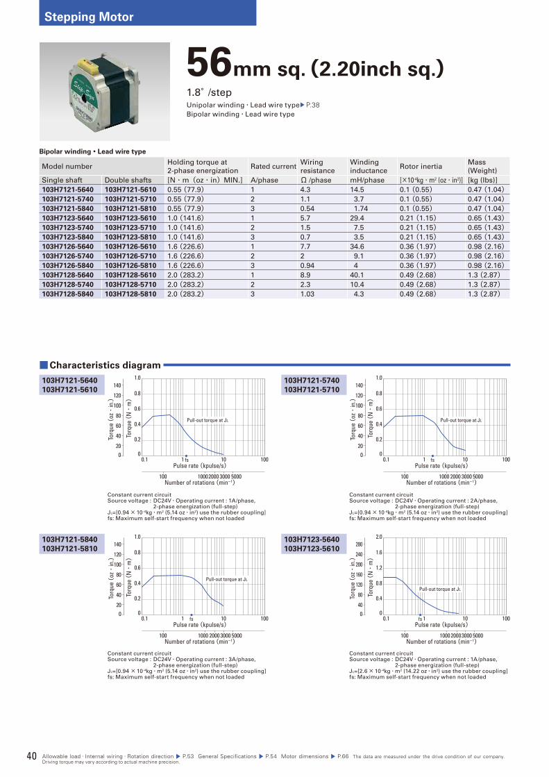
40
Stepping Motor
56mm sq.(2.20inch sq.)1.8°/stepUnipolar winding・Lead wire type P.38Bipolar winding・Lead wire type
Bipolar winding・Lead wire type
Model numberHolding torque at
2-phase energizationRated current
Wiring
resistance
Winding
inductanceRotor inertia
Mass
(Weight)
Single shaft Double shafts [N・m(oz・in)MIN.] A/phase Ω /phase mH/phase [×10-4kg・m2 (oz・in2)] [kg (Ibs)]
103H7121-5640 103H7121-5610 0.55 (77.9) 1 4.3 14.5 0.1 (0.55) 0.47 (1.04)103H7121-5740 103H7121-5710 0.55 (77.9) 2 1.1 3.7 0.1 (0.55) 0.47 (1.04)103H7121-5840 103H7121-5810 0.55 (77.9) 3 0.54 1.74 0.1 (0.55) 0.47 (1.04)103H7123-5640 103H7123-5610 1.0 (141.6) 1 5.7 29.4 0.21 (1.15) 0.65 (1.43)103H7123-5740 103H7123-5710 1.0 (141.6) 2 1.5 7.5 0.21 (1.15) 0.65 (1.43)103H7123-5840 103H7123-5810 1.0 (141.6) 3 0.7 3.5 0.21 (1.15) 0.65 (1.43)103H7126-5640 103H7126-5610 1.6 (226.6) 1 7.7 34.6 0.36 (1.97) 0.98 (2.16)103H7126-5740 103H7126-5710 1.6 (226.6) 2 2 9.1 0.36 (1.97) 0.98 (2.16)103H7126-5840 103H7126-5810 1.6 (226.6) 3 0.94 4 0.36 (1.97) 0.98 (2.16)103H7128-5640 103H7128-5610 2.0 (283.2) 1 8.9 40.1 0.49 (2.68) 1.3 (2.87)103H7128-5740 103H7128-5710 2.0 (283.2) 2 2.3 10.4 0.49 (2.68) 1.3 (2.87)103H7128-5840 103H7128-5810 2.0 (283.2) 3 1.03 4.3 0.49 (2.68) 1.3 (2.87)
Constant current circuitSource voltage : DC24V・Operating current : 1A/phase, 2-phase energization (full-step)JL=[0.94× 10⁻⁴kg・m2 (5.14 oz・in2) use the rubber coupling]fs: Maximum self-start frequency when not loaded
Constant current circuitSource voltage : DC24V・Operating current : 2A/phase, 2-phase energization (full-step)JL=[0.94× 10⁻⁴kg・m2 (5.14 oz・in2) use the rubber coupling]fs: Maximum self-start frequency when not loaded
103H7121-5740
103H7121-5710
■Characteristics diagram
103H7121-5640
103H7121-5610
103H7121-5840
103H7121-5810
103H7123-5640
103H7123-5610
Constant current circuitSource voltage : DC24V・Operating current : 3A/phase, 2-phase energization (full-step)JL=[0.94 × 10⁻⁴kg・m2 (5.14 oz・in2) use the rubber coupling]fs: Maximum self-start frequency when not loaded
Constant current circuitSource voltage : DC24V・Operating current : 1A/phase, 2-phase energization (full-step)JL=[2.6× 10⁻⁴kg・m2 (14.22 oz・in2) use the rubber coupling]fs: Maximum self-start frequency when not loaded
Torq
ue (
N・
m)
0.1 1 10 100
10002000 3000 5000100
0.2
0.4
0.6
0.8
1.0
0
Pulse rate (kpulse/s)
Number of rotations (min-1)
fs0
Torq
ue (
oz・
in.)
140
120
100
80
60
40
20
Pull-out torque at JL
Torq
ue (
N・
m)
0.1 1 10 100
1000 2000 3000 5000100
0.2
0.4
0.6
0.8
1.0
0
Pulse rate (kpulse/s)
Number of rotations (min-1)
fs0
Torq
ue (
oz・
in.)
140
120
100
80
60
40
20
Pull-out torque at JL
Torq
ue (
N・
m)
0.1 1 10 100
1000 2000 3000 5000100
0.2
0.4
0.6
0.8
1.0
0
Pulse rate (kpulse/s)
Number of rotations (min-1)
fs0
Torq
ue (
oz・
in.)
140
120
100
80
60
40
20
Pull-out torque at JL
Torq
ue (
N・
m)
0.1 1 10 100
1000 20003000 5000100
0.4
0.8
1.2
1.6
2.0
0
Pulse rate (kpulse/s)
Number of rotations (min-1)
fs0
Torq
ue (
oz・
in.)
280
200
240
160
120
80
40
Pull-out torque at JL
Allowable load・Internal wiring・Rotation direction P.53 General Specifications P.54 Motor dimensions P.66 The data are measured under the drive condition of our company. Driving torque may vary according to actual machine precision.
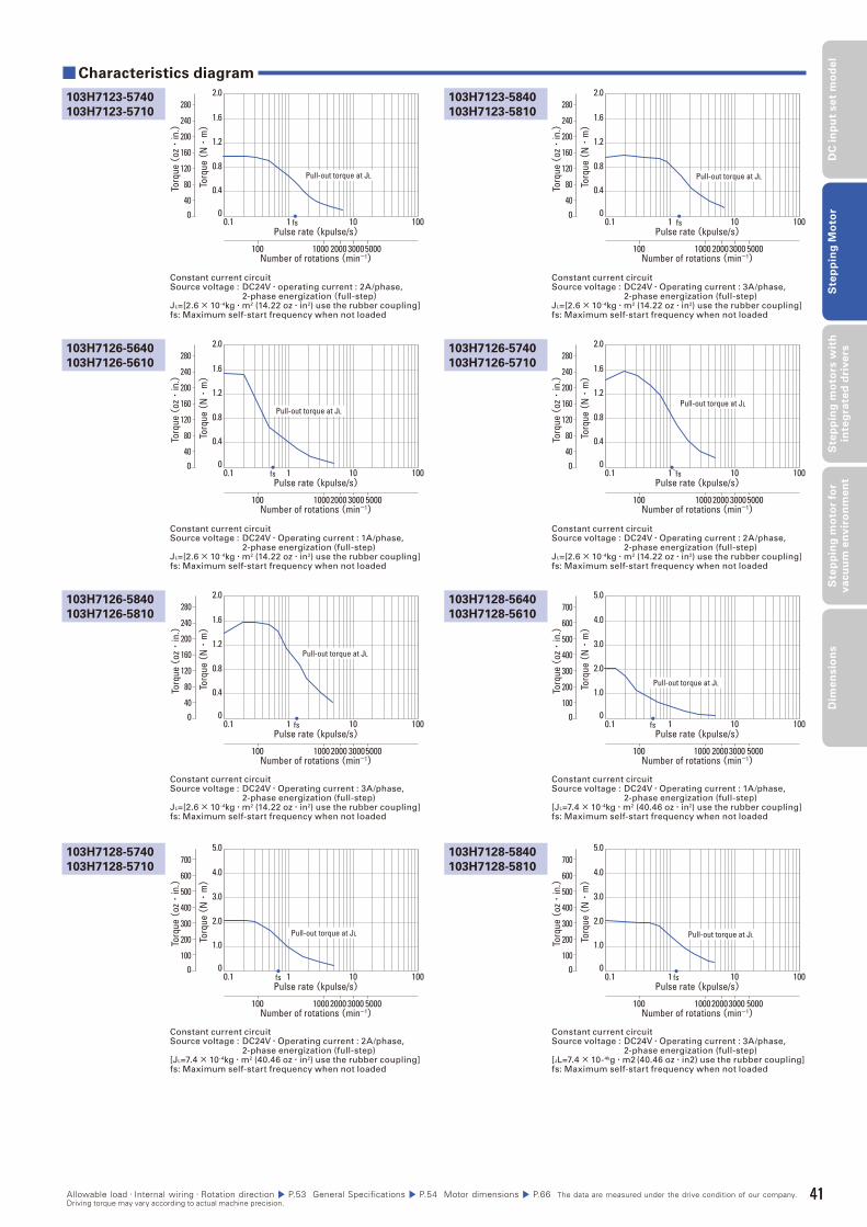
41
DC
in
pu
t se
t m
od
el
Ste
pp
ing
Mo
tor
Ste
pp
ing
mo
tors
wit
h
inte
gra
ted
dri
ve
rsS
tep
pin
g m
oto
r fo
r v
acu
um
en
vir
on
me
nt
Dim
en
sio
ns
Constant current circuitSource voltage : DC24V・Operating current : 1A/phase, 2-phase energization (full-step)JL=[2.6× 10⁻⁴kg・m2 (14.22 oz・in2) use the rubber coupling]fs: Maximum self-start frequency when not loaded
Constant current circuitSource voltage : DC24V・operating current : 2A/phase, 2-phase energization(full-step)JL=[2.6× 10⁻⁴kg・m2 (14.22 oz・in2) use the rubber coupling]fs: Maximum self-start frequency when not loaded
Constant current circuitSource voltage : DC24V・Operating current : 2A/phase, 2-phase energization (full-step)JL=[2.6× 10⁻⁴kg・m2 (14.22 oz・in2) use the rubber coupling]fs: Maximum self-start frequency when not loaded
Constant current circuitSource voltage : DC24V・Operating current : 3A/phase, 2-phase energization (full-step)JL=[2.6× 10⁻⁴kg・m2 (14.22 oz・in2) use the rubber coupling]fs: Maximum self-start frequency when not loaded
103H7126-5740
103H7126-5710
103H7123-5840
103H7123-5810
■ Characteristics diagram
103H7126-5640
103H7126-5610
103H7123-5740
103H7123-5710
103H7126-5840
103H7126-5810
103H7128-5740
103H7128-5710
103H7128-5640
103H7128-5610
103H7128-5840
103H7128-5810
Constant current circuitSource voltage : DC24V・Operating current : 3A/phase, 2-phase energization (full-step)JL=[2.6× 10⁻⁴kg・m2 (14.22 oz・in2) use the rubber coupling]fs: Maximum self-start frequency when not loaded
Constant current circuitSource voltage : DC24V・Operating current : 2A/phase, 2-phase energization (full-step)[JL=7.4× 10⁻⁴kg・m2 (40.46 oz・in2) use the rubber coupling]fs: Maximum self-start frequency when not loaded
Constant current circuitSource voltage : DC24V・Operating current : 1A/phase, 2-phase energization (full-step)[JL=7.4× 10⁻⁴kg・m2 (40.46 oz・in2) use the rubber coupling]fs: Maximum self-start frequency when not loaded
Constant current circuitSource voltage : DC24V・Operating current : 3A/phase, 2-phase energization (full-step)[JL=7.4× 10⁻⁴kg・m2 (40.46 oz・in2) use the rubber coupling]fs: Maximum self-start frequency when not loaded
Torq
ue (
N・
m)
0.1 1 10 100
10002000 3000 5000100
0.4
0.8
1.2
1.6
2.0
0
Pulse rate (kpulse/s)
Number of rotations (min-1)
fs0
Torq
ue (
oz・
in.)
280
200
240
160
120
80
40
Pull-out torque at JL
Torq
ue (
N・
m)
0.1 1 10 100
1000 2000 30005000100
0.4
0.8
1.2
1.6
2.0
0
Pulse rate (kpulse/s)
Number of rotations (min-1)
fs0
Torq
ue (
oz・
in.)
280
200
240
160
120
80
40
Pull-out torque at JL
Torq
ue (
N・
m)
0.1 1 10 100
1000 2000 30005000100
0.4
0.8
1.2
1.6
2.0
0
Pulse rate (kpulse/s)
Number of rotations (min-1)
fs0
Torq
ue (
oz・
in.)
280
200
240
160
120
80
40
Pull-out torque at JL
Torq
ue (
N・
m)
0.1 1 10 100
1000 20003000 5000100
0.4
0.8
1.2
1.6
2.0
0
Pulse rate (kpulse/s)
Number of rotations (min-1)
fs0
Torq
ue (
oz・
in.)
280
200
240
160
120
80
40
Pull-out torque at JL
Torq
ue (
N・
m)
0.1 1 10 100
1000 2000 30005000100
0.4
0.8
1.2
1.6
2.0
0
Pulse rate (kpulse/s)
Number of rotations (min-1)
fs0
Torq
ue (
oz・
in.)
280
200
240
160
120
80
40
Pull-out torque at JL
Torq
ue (
N・
m)
0.1 1 10 100
1000 2000 3000 5000100
1.0
2.0
3.0
4.0
5.0
0
Pulse rate (kpulse/s)
Number of rotations (min-1)
fs0
Torq
ue (
oz・
in.)
700
600
500
400
300
200
100
Pull-out torque at JL
Torq
ue (
N・
m)
0.1 1 10 100
1000 20003000 5000100
1.0
2.0
3.0
4.0
5.0
0
Pulse rate (kpulse/s)
Number of rotations (min-1)
fs0
Torq
ue (
oz・
in.)
700
600
500
400
300
200
100
Pull-out torque at JL
Torq
ue (
N・
m)
0.1 1 10 100
100020003000 5000100
1.0
2.0
3.0
4.0
5.0
0
Pulse rate (kpulse/s)
Number of rotations (min-1)
fs0
Torq
ue (
oz・
in.)
700
600
500
400
300
200
100
Pull-out torque at JL
Allowable load・Internal wiring・Rotation direction P.53 General Specifications P.54 Motor dimensions P.66 The data are measured under the drive condition of our company. Driving torque may vary according to actual machine precision.
41
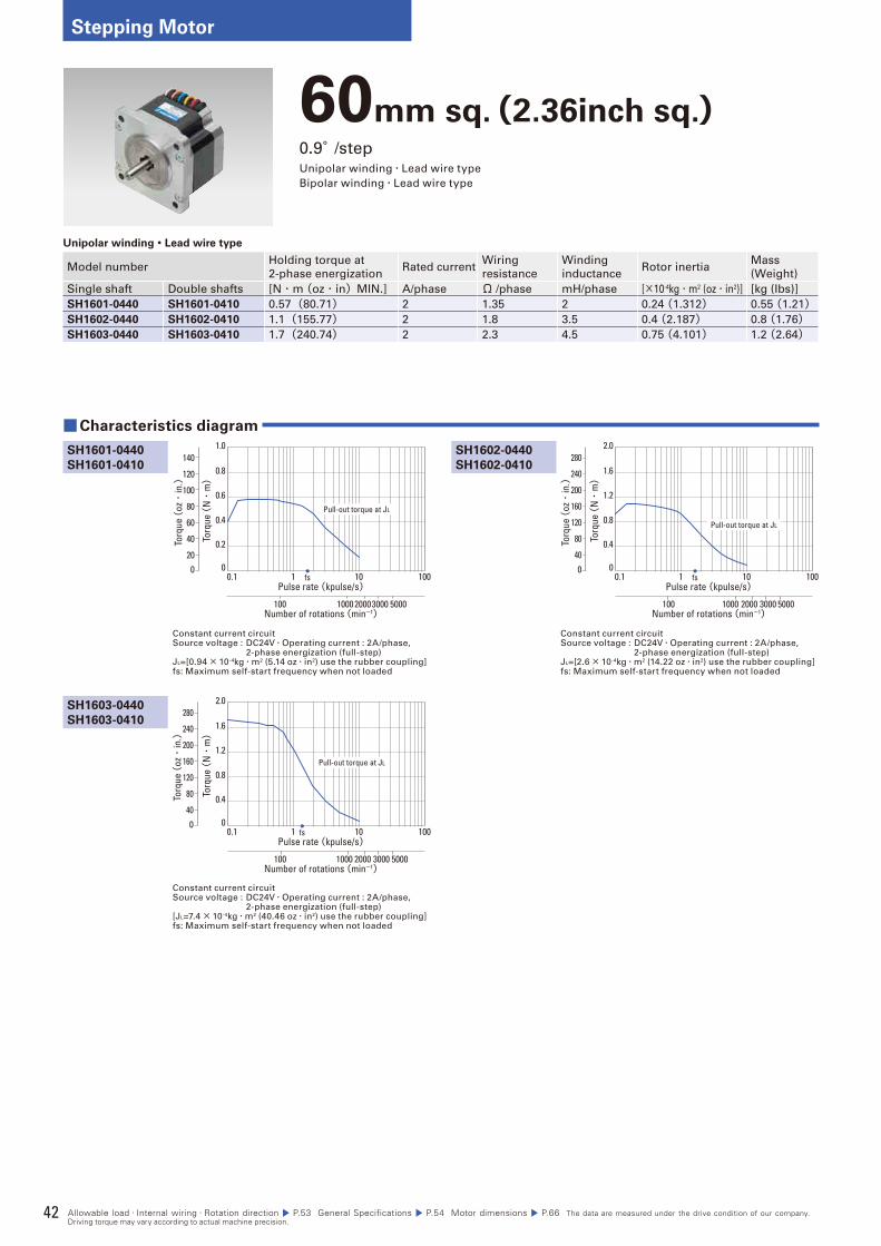
42
Stepping Motor
60mm sq.(2.36inch sq.)0.9°/stepUnipolar winding・Lead wire type
Bipolar winding・Lead wire type
Unipolar winding・Lead wire type
Model numberHolding torque at
2-phase energizationRated current
Wiring
resistance
Winding
inductanceRotor inertia
Mass
(Weight)
Single shaft Double shafts [N・m (oz・in)MIN.] A/phase Ω /phase mH/phase [×10-4kg・m2 (oz・in2)] [kg (Ibs)]
SH1601-0440 SH1601-0410 0.57 (80.71) 2 1.35 2 0.24 (1.312) 0.55 (1.21)SH1602-0440 SH1602-0410 1.1 (155.77) 2 1.8 3.5 0.4 (2.187) 0.8 (1.76)SH1603-0440 SH1603-0410 1.7 (240.74) 2 2.3 4.5 0.75 (4.101) 1.2 (2.64)
Constant current circuitSource voltage : DC24V・Operating current : 2A/phase, 2-phase energization (full-step)JL=[0.94× 10⁻⁴kg・m2 (5.14 oz・in2) use the rubber coupling]fs: Maximum self-start frequency when not loaded
Constant current circuitSource voltage : DC24V・Operating current : 2A/phase, 2-phase energization (full-step)JL=[2.6× 10⁻⁴kg・m2 (14.22 oz・in2) use the rubber coupling]fs: Maximum self-start frequency when not loaded
SH1602-0440
SH1602-0410
■Characteristics diagram
SH1601-0440
SH1601-0410
SH1603-0440
SH1603-0410
Constant current circuitSource voltage : DC24V・Operating current : 2A/phase, 2-phase energization (full-step)[JL=7.4× 10⁻⁴kg・m2 (40.46 oz・in2) use the rubber coupling]fs: Maximum self-start frequency when not loaded
Torq
ue (
N・
m)
0.1 1 10 100
0.2
0.4
0.6
0.8
1.0
0
Pulse rate (kpulse/s)
Number of rotations (min-1)
fs
100020003000 5000100
0
Torq
ue (
oz・
in.)
140
120
100
80
60
40
20
Pull-out torque at JL
Torq
ue (
N・
m)
0.1 1 10 100
0.4
0.8
1.2
1.6
2.0
0
1000 2000 3000 5000100
Pulse rate (kpulse/s)
Number of rotations (min-1)
fs0
Torq
ue (
oz・
in.)
280
200
240
160
120
80
40
Pull-out torque at JL
Torq
ue (
N・
m)
0.1 1 10 100
0.4
0.8
1.2
1.6
2.0
0
1000 2000 3000 5000100
Pulse rate (kpulse/s)
Number of rotations (min-1)
fs0
Torq
ue (
oz・
in.)
280
200
240
160
120
80
40
Pull-out torque at JL
Allowable load・Internal wiring・Rotation direction P.53 General Specifications P.54 Motor dimensions P.66 The data are measured under the drive condition of our company. Driving torque may vary according to actual machine precision.
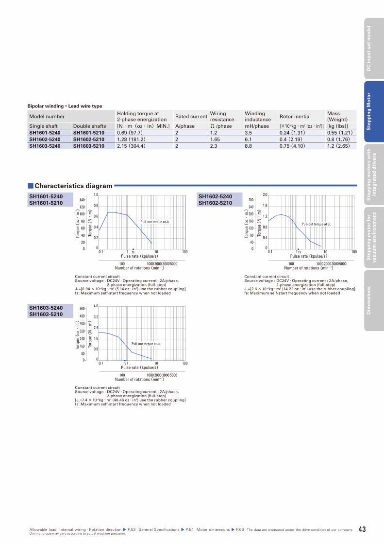
43
DC
in
pu
t se
t m
od
el
Ste
pp
ing
Mo
tor
Ste
pp
ing
mo
tors
wit
h
inte
gra
ted
dri
ve
rsS
tep
pin
g m
oto
r fo
r v
acu
um
en
vir
on
me
nt
Dim
en
sio
ns
Bipolar winding・Lead wire type
Model numberHolding torque at
2-phase energizationRated current
Wiring
resistance
Winding
inductanceRotor inertia
Mass
(Weight)
Single shaft Double shafts [N・m(oz・in)MIN.] A/phase Ω /phase mH/phase [×10-4kg・m2 (oz・in2)] [kg (Ibs)]
SH1601-5240 SH1601-5210 0.69 (97.7) 2 1.2 3.5 0.24 (1.31) 0.55 (1.21)SH1602-5240 SH1602-5210 1.28 (181.2) 2 1.65 6.1 0.4 (2.19) 0.8 (1.76)SH1603-5240 SH1603-5210 2.15 (304.4) 2 2.3 8.8 0.75 (4.10) 1.2 (2.65)
Constant current circuitSource voltage : DC24V・Operating current : 2A/phase, 2-phase energization (full-step)JL=[0.94× 10⁻⁴kg・m2 (5.14 oz・in2) use the rubber coupling]fs: Maximum self-start frequency when not loaded
Constant current circuitSource voltage : DC24V・Operating current : 2A/phase, 2-phase energization (full-step)JL=[2.6× 10⁻⁴kg・m2 (14.22 oz・in2) use the rubber coupling]fs: Maximum self-start frequency when not loaded
SH1602-5240
SH1602-5210
■ Characteristics diagram
SH1601-5240
SH1601-5210
SH1603-5240
SH1603-5210
Constant current circuitSource voltage : DC24V・Operating current : 2A/phase, 2-phase energization (full-step)[JL=7.4× 10⁻⁴kg・m2 (40.46 oz・in2) use the rubber coupling]fs: Maximum self-start frequency when not loaded
Torq
ue (
N・
m)
0.1 1 10 100
0.2
0.4
0.6
0.8
1.0
0
1000 2000 30005000100
Pulse rate (kpulse/s)
Number of rotations (min-1)
fs0
Torq
ue (
oz・
in.)
140
120
100
80
60
40
20
Pull-out torque at JL
Torq
ue (
N・
m)
0.1 1 10 100
0.4
0.8
1.2
1.6
2.0
0
10002000 30005000100
Pulse rate (kpulse/s)
Number of rotations (min-1)
fs0
Torq
ue (
oz・
in.)
280
200
240
160
120
80
40
Pull-out torque at JL
Torq
ue (
N・
m)
0.1 1 10 100
0.8
1.6
2.4
3.2
4.0
0
10002000 3000 5000100
Pulse rate (kpulse/s)
Number of rotations (min-1)
fs
Torq
ue (
oz・
in.)
560
0
480
400
320
240
160
80
Pull-out torque at JL
Allowable load・Internal wiring・Rotation direction P.53 General Specifications P.54 Motor dimensions P.66 The data are measured under the drive condition of our company. Driving torque may vary according to actual machine precision.
43
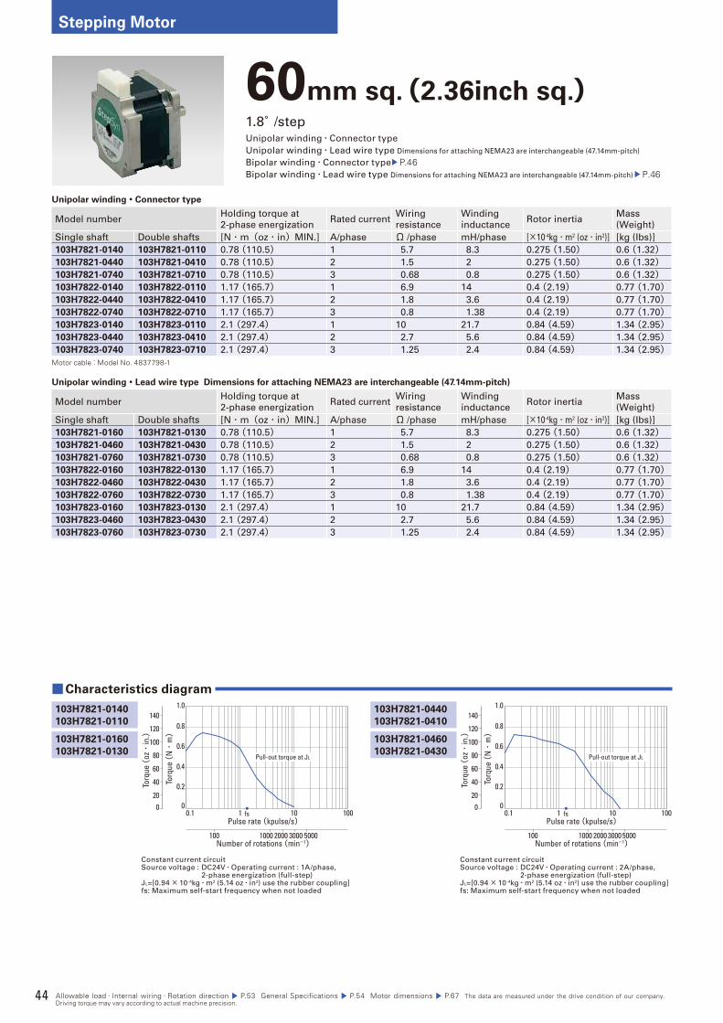
44
Stepping Motor
60mm sq.(2.36inch sq.)1.8°/stepUnipolar winding・Connector type
Unipolar winding・Lead wire type Dimensions for attaching NEMA23 are interchangeable (47.14mm-pitch)
Bipolar winding・Connector type P.46Bipolar winding・Lead wire type Dimensions for attaching NEMA23 are interchangeable (47.14mm-pitch) P.46
Unipolar winding・Connector type
Model numberHolding torque at
2-phase energizationRated current
Wiring
resistance
Winding
inductanceRotor inertia
Mass
(Weight)
Single shaft Double shafts [N・m(oz・in)MIN.] A/phase Ω /phase mH/phase [×10-4kg・m2 (oz・in2)] [kg (Ibs)]
103H7821-0140 103H7821-0110 0.78 (110.5) 1 5.7 8.3 0.275 (1.50) 0.6 (1.32)103H7821-0440 103H7821-0410 0.78 (110.5) 2 1.5 2 0.275 (1.50) 0.6 (1.32)103H7821-0740 103H7821-0710 0.78 (110.5) 3 0.68 0.8 0.275 (1.50) 0.6 (1.32)103H7822-0140 103H7822-0110 1.17 (165.7) 1 6.9 14 0.4 (2.19) 0.77 (1.70)103H7822-0440 103H7822-0410 1.17 (165.7) 2 1.8 3.6 0.4 (2.19) 0.77 (1.70)103H7822-0740 103H7822-0710 1.17 (165.7) 3 0.8 1.38 0.4 (2.19) 0.77 (1.70)103H7823-0140 103H7823-0110 2.1 (297.4) 1 10 21.7 0.84 (4.59) 1.34 (2.95)103H7823-0440 103H7823-0410 2.1 (297.4) 2 2.7 5.6 0.84 (4.59) 1.34 (2.95)103H7823-0740 103H7823-0710 2.1 (297.4) 3 1.25 2.4 0.84 (4.59) 1.34 (2.95)
Motor cable:Model No. 4837798-1
Unipolar winding・Lead wire type Dimensions for attaching NEMA23 are interchangeable (47.14mm-pitch)
Model numberHolding torque at
2-phase energizationRated current
Wiring
resistance
Winding
inductanceRotor inertia
Mass
(Weight)
Single shaft Double shafts [N・m(oz・in)MIN.] A/phase Ω /phase mH/phase [×10-4kg・m2 (oz・in2)] [kg (Ibs)]
103H7821-0160 103H7821-0130 0.78 (110.5) 1 5.7 8.3 0.275 (1.50) 0.6 (1.32)103H7821-0460 103H7821-0430 0.78 (110.5) 2 1.5 2 0.275 (1.50) 0.6 (1.32)103H7821-0760 103H7821-0730 0.78 (110.5) 3 0.68 0.8 0.275 (1.50) 0.6 (1.32)103H7822-0160 103H7822-0130 1.17 (165.7) 1 6.9 14 0.4 (2.19) 0.77 (1.70)103H7822-0460 103H7822-0430 1.17 (165.7) 2 1.8 3.6 0.4 (2.19) 0.77 (1.70)103H7822-0760 103H7822-0730 1.17 (165.7) 3 0.8 1.38 0.4 (2.19) 0.77 (1.70)103H7823-0160 103H7823-0130 2.1 (297.4) 1 10 21.7 0.84 (4.59) 1.34 (2.95)103H7823-0460 103H7823-0430 2.1 (297.4) 2 2.7 5.6 0.84 (4.59) 1.34 (2.95)103H7823-0760 103H7823-0730 2.1 (297.4) 3 1.25 2.4 0.84 (4.59) 1.34 (2.95)
Constant current circuitSource voltage : DC24V・Operating current : 1A/phase, 2-phase energization (full-step)JL=[0.94× 10⁻⁴kg・m2 (5.14 oz・in2) use the rubber coupling]fs: Maximum self-start frequency when not loaded
Constant current circuitSource voltage : DC24V・Operating current : 2A/phase, 2-phase energization (full-step)JL=[0.94× 10⁻⁴kg・m2 (5.14 oz・in2) use the rubber coupling]fs: Maximum self-start frequency when not loaded
103H7821-0440
103H7821-0410
■Characteristics diagram
103H7821-0140
103H7821-0110
Torq
ue (
N・
m)
Pulse rate (kpulse/s)
Number of rotations (min-1)
0.1 1 10 100
1000 2000 3000 5000100
fs
0.2
0.4
0.6
0.8
1.0
00
Torq
ue (
oz・
in.)
140
120
100
80
60
40
20
Pull-out torque at JL
Torq
ue (
N・
m)
Pulse rate (kpulse/s)
Number of rotations (min-1)
0.1 1 10 100
1000 2000 3000 5000100
fs
0.2
0.4
0.6
0.8
1.0
00
Torq
ue (
oz・
in.)
140
120
100
80
60
40
20
Pull-out torque at JL
103H7821-0460
103H7821-0430
103H7821-0160
103H7821-0130
Allowable load・Internal wiring・Rotation direction P.53 General Specifications P.54 Motor dimensions P.67 The data are measured under the drive condition of our company. Driving torque may vary according to actual machine precision.
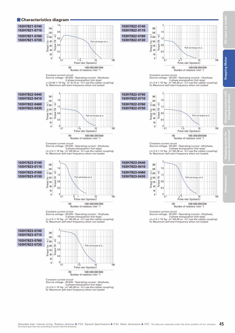
45
DC
in
pu
t se
t m
od
el
Ste
pp
ing
Mo
tor
Ste
pp
ing
mo
tors
wit
h
inte
gra
ted
dri
ve
rsS
tep
pin
g m
oto
r fo
r v
acu
um
en
vir
on
me
nt
Dim
en
sio
ns
103H7821-0740
103H7821-0710
103H7822-0140
103H7822-0110
Constant current circuitSource voltage : DC24V・Operating current : 3A/phase, 2-phase energization (full-step)JL=[0.94× 10⁻⁴kg・m2 (5.14 oz・in2) use the rubber coupling]fs: Maximum self-start frequency when not loaded
Constant current circuitSource voltage : DC24V・Operating current : 1A/phase, 2-phase energization (full-step)[JL=7.4× 10⁻⁴kg・m2 (40.46 oz・in2) use the rubber coupling]fs: Maximum self-start frequency when not loaded
Torq
ue (
N・
m)
Pulse rate (kpulse/s)
Number of rotations (min-1)
0.1 1 10 100
1000 20003000 5000100
fs
0.2
0.4
0.6
0.8
1.0
00
Torq
ue (
oz・
in.)
140
120
100
80
60
40
20
Pull-out torque at JL
Torq
ue (
N・
m)
Pulse rate (kpulse/s)
Number of rotations (min-1)
0.1 1 10 100
100020003000 5000100
fs
0.4
0.8
1.2
1.6
2
00
Torq
ue (
oz・
in.)
280
200
240
160
120
80
40
Pull-out torque at JL
103H7821-0760
103H7821-0730
103H7822-0160
103H7822-0130
Constant current circuitSource voltage : DC24V・Operating current : 1A/phase, 2-phase energization (full-step)[JL=7.4× 10⁻⁴kg・m2 (40.46 oz・in2) use the rubber coupling]fs: Maximum self-start frequency when not loaded
Constant current circuitSource voltage : DC24V・Operating current : 2A/phase, 2-phase energization (full-step)[JL=7.4× 10⁻⁴kg・m2 (40.46 oz・in2) use the rubber coupling]fs: Maximum self-start frequency when not loaded
Constant current circuitSource voltage : DC24V・Operating current : 2A/phase, 2-phase energization (full-step)[JL=7.4× 10⁻⁴kg・m2 (40.46 oz・in2) use the rubber coupling]fs: Maximum self-start frequency when not loaded
Constant current circuitSource voltage : DC24V・Operating current : 3A/phase, 2-phase energization (full-step)[JL=7.4× 10⁻⁴kg・m2 (40.46 oz・in2) use the rubber coupling]fs: Maximum self-start frequency when not loaded
103H7823-0440
103H7823-0410
103H7822-0740
103H7822-0710
■Characteristics diagram
103H7823-0140
103H7823-0110
103H7822-0440
103H7822-0410
103H7823-0740
103H7823-0710
Constant current circuitSource voltage : DC24V・Operating current : 3A/phase, 2-phase energization (full-step)[JL=7.4× 10⁻⁴kg・m2 (40.46 oz・in2) use the rubber coupling]fs: Maximum self-start frequency when not loaded
Torq
ue (
N・
m)
Pulse rate (kpulse/s)
Number of rotations (min-1)
0.1 1 10 100
1000 20003000 5000100
fs
0.4
0.8
1.2
1.6
2
00
Torq
ue (
oz・
in.)
280
200
240
160
120
80
40
Pull-out torque at JL
Torq
ue (
N・
m)
Pulse rate (kpulse/s)
Number of rotations (min-1)
0.1 1 10 100
1000 2000 30005000100
fs
0.4
0.8
1.2
1.6
2
00
Torq
ue (
oz・
in.)
280
200
240
160
120
80
40
Pull-out torque at JL
Pulse rate (kpulse/s)
Number of rotations (min-1)
0.1 1 10 100
1000 2000 3000 5000100
fs
Torq
ue (
N・
m)
0.4
0.8
1.2
1.6
2
00
Torq
ue (
oz・
in.)
280
200
240
160
120
80
40
Pull-out torque at JL
Torq
ue (
N・
m)
Pulse rate (kpulse/s)
Number of rotations (min-1)
0.1 1 10 100
1000 200030005000100
fs
0.4
0.8
1.2
1.6
2
00
Torq
ue (
oz・
in.)
280
200
240
160
120
80
40
Pull-out torque at JL
Torq
ue (
N・
m)
Pulse rate (kpulse/s)
Number of rotations (min-1)
0.1 1 10 100
1000 2000 3000 5000100
fs
0.4
0.8
1.2
1.6
2
00
Torq
ue (
oz・
in.)
280
200
240
160
120
80
40
Pull-out torque at JL
103H7823-0460
103H7823-0430
103H7822-0760
103H7822-0730
103H7823-0160
103H7823-0130
103H7822-0460
103H7822-0430
103H7823-0760
103H7823-0730
Allowable load・Internal wiring・Rotation direction P.53 General Specifications P.54 Motor dimensions P.67 The data are measured under the drive condition of our company. Driving torque may vary according to actual machine precision.
45
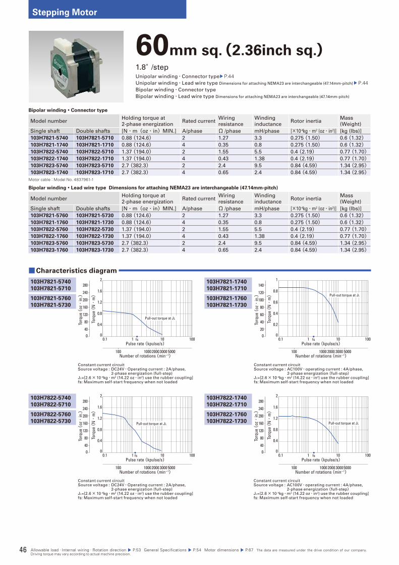
46
Stepping Motor
60mm sq.(2.36inch sq.)1.8°/stepUnipolar winding・Connector type P.44Unipolar winding・Lead wire type Dimensions for attaching NEMA23 are interchangeable (47.14mm-pitch) P.44Bipolar winding・Connector type
Bipolar winding・Lead wire type Dimensions for attaching NEMA23 are interchangeable (47.14mm-pitch)
Bipolar winding・Connector type
Model numberHolding torque at
2-phase energizationRated current
Wiring
resistance
Winding
inductanceRotor inertia
Mass
(Weight)
Single shaft Double shafts [N・m(oz・in)MIN.] A/phase Ω /phase mH/phase [×10-4kg・m2 (oz・in2)] [kg (Ibs)]
103H7821-5740 103H7821-5710 0.88 (124.6) 2 1.27 3.3 0.275 (1.50) 0.6 (1.32)103H7821-1740 103H7821-1710 0.88 (124.6) 4 0.35 0.8 0.275 (1.50) 0.6 (1.32)103H7822-5740 103H7822-5710 1.37 (194.0) 2 1.55 5.5 0.4 (2.19) 0.77 (1.70)103H7822-1740 103H7822-1710 1.37 (194.0) 4 0.43 1.38 0.4 (2.19) 0.77 (1.70)103H7823-5740 103H7823-5710 2.7 (382.3) 2 2.4 9.5 0.84 (4.59) 1.34 (2.95)103H7823-1740 103H7823-1710 2.7 (382.3) 4 0.65 2.4 0.84 (4.59) 1.34 (2.95)
Motor cable:Model No. 4837961-1
Bipolar winding・Lead wire type Dimensions for attaching NEMA23 are interchangeable (47.14mm-pitch)
Model numberHolding torque at
2-phase energizationRated current
Wiring
resistance
Winding
inductanceRotor inertia
Mass
(Weight)
Single shaft Double shafts [N・m(oz・in)MIN.] A/phase Ω /phase mH/phase [×10-4kg・m2 (oz・in2)] [kg (Ibs)]
103H7821-5760 103H7821-5730 0.88 (124.6) 2 1.27 3.3 0.275 (1.50) 0.6 (1.32)103H7821-1760 103H7821-1730 0.88 (124.6) 4 0.35 0.8 0.275 (1.50) 0.6 (1.32)103H7822-5760 103H7822-5730 1.37 (194.0) 2 1.55 5.5 0.4 (2.19) 0.77 (1.70)103H7822-1760 103H7822-1730 1.37 (194.0) 4 0.43 1.38 0.4 (2.19) 0.77 (1.70)103H7823-5760 103H7823-5730 2.7 (382.3) 2 2.4 9.5 0.84 (4.59) 1.34 (2.95)103H7823-1760 103H7823-1730 2.7 (382.3) 4 0.65 2.4 0.84 (4.59) 1.34 (2.95)
Constant current circuitSource voltage : DC24V・Operating current : 2A/phase, 2-phase energization (full-step)JL=[2.6× 10⁻⁴kg・m2 (14.22 oz・in2) use the rubber coupling]fs: Maximum self-start frequency when not loaded
Constant current circuitSource voltage : AC100V・operating current : 4A/phase, 2-phase energization(full-step)JL=[2.6× 10⁻⁴kg・m2 (14.22 oz・in2) use the rubber coupling]fs: Maximum self-start frequency when not loaded
103H7821-1740
103H7821-1710
■Characteristics diagram
103H7821-5740
103H7821-5710
103H7822-5740
103H7822-5710
103H7822-1740
103H7822-1710
Constant current circuitSource voltage : DC24V・Operating current : 2A/phase, 2-phase energization (full-step)JL=[2.6× 10⁻⁴kg・m2 (14.22 oz・in2) use the rubber coupling]fs: Maximum self-start frequency when not loaded
Constant current circuitSource voltage : AC100V・operating current : 4A/phase, 2-phase energization(full-step)JL=[2.6× 10⁻⁴kg・m2 (14.22 oz・in2) use the rubber coupling]fs: Maximum self-start frequency when not loaded
Torq
ue (
N・
m)
Pulse rate (kpulse/s)
Number of rotations (min-1)
0.1 1 10 100
1000 20003000 5000100
fs
0.4
0.8
1.2
1.6
2
00
Torq
ue (
oz・
in.)
280
200
240
160
120
80
40
Pull-out torque at JL
Torq
ue (
N・
m)
Pulse rate (kpulse/s)
Number of rotations (min-1)
0.1 1 10 100
1000 2000 3000 5000100
fs
0.2
0.4
0.6
0.8
1
00
Torq
ue (
oz・
in.)
140
120
100
80
60
40
20
Pull-out torque at JL
Torq
ue (
N・
m)
Pulse rate (kpulse/s)
Number of rotations (min-1)
0.1 1 10 100
1000 2000 3000 5000100
fs
0.4
0.8
1.2
1.6
2
00
Torq
ue (
oz・
in.)
280
200
240
160
120
80
40
Pull-out torque at JL
Torq
ue (
N・
m)
Pulse rate (kpulse/s)
Number of rotations (min-1)
0.1 1 10 100
1000 2000 30005000100
fs
0.4
0.8
1.2
1.6
2
00
Torq
ue (
oz・
in.)
280
200
240
160
120
80
40
Pull-out torque at JL
103H7821-1760
103H7821-1730
103H7821-5760
103H7821-5730
103H7822-5760
103H7822-5730
103H7822-1760
103H7822-1730
Allowable load・Internal wiring・Rotation direction P.53 General Specifications P.54 Motor dimensions P.67 The data are measured under the drive condition of our company. Driving torque may vary according to actual machine precision.

47
DC
in
pu
t se
t m
od
el
Ste
pp
ing
Mo
tor
Ste
pp
ing
mo
tors
wit
h
inte
gra
ted
dri
ve
rsS
tep
pin
g m
oto
r fo
r v
acu
um
en
vir
on
me
nt
Dim
en
sio
ns
Constant current circuitSource voltage : DC24V・Operating current : 2A/phase, 2-phase energization (full-step)[JL=7.4× 10⁻⁴kg・m2 (40.46 oz・in2) use the rubber coupling]fs: Maximum self-start frequency when not loaded
Constant current circuitSource voltage : AC100V・operating current : 4A/phase, 2-phase energization(full-step)[JL=7.4× 10⁻⁴kg・m2 (40.46 oz・in2) use the rubber coupling]fs: Maximum self-start frequency when not loaded
103H7823-1740
103H7823-1710
■ Characteristics diagram
103H7823-5740
103H7823-5710
Torq
ue (
N・
m)
Pulse rate (kpulse/s)
Number of rotations (min-1)
0.1 1 10 100
1000 2000 3000 5000100
fs
1
2
3
4
5
00
Torq
ue (
oz・
in.)
700
600
500
400
300
200
100
Pull-out torque at JL
Torq
ue (
N・
m)
Pulse rate (kpulse/s)
Number of rotations (min-1)
0.1 1 10 100
1000 20003000 5000100
fs
1
2
3
4
5
00
Torq
ue (
oz・
in.)
700
600
500
400
300
200
100
Pull-out torque at JL
103H7823-1760
103H7823-1730
103H7823-5760
103H7823-5730
Allowable load・Internal wiring・Rotation direction P.53 General Specifications P.54 Motor dimensions P.67 The data are measured under the drive condition of our company. Driving torque may vary according to actual machine precision.
47
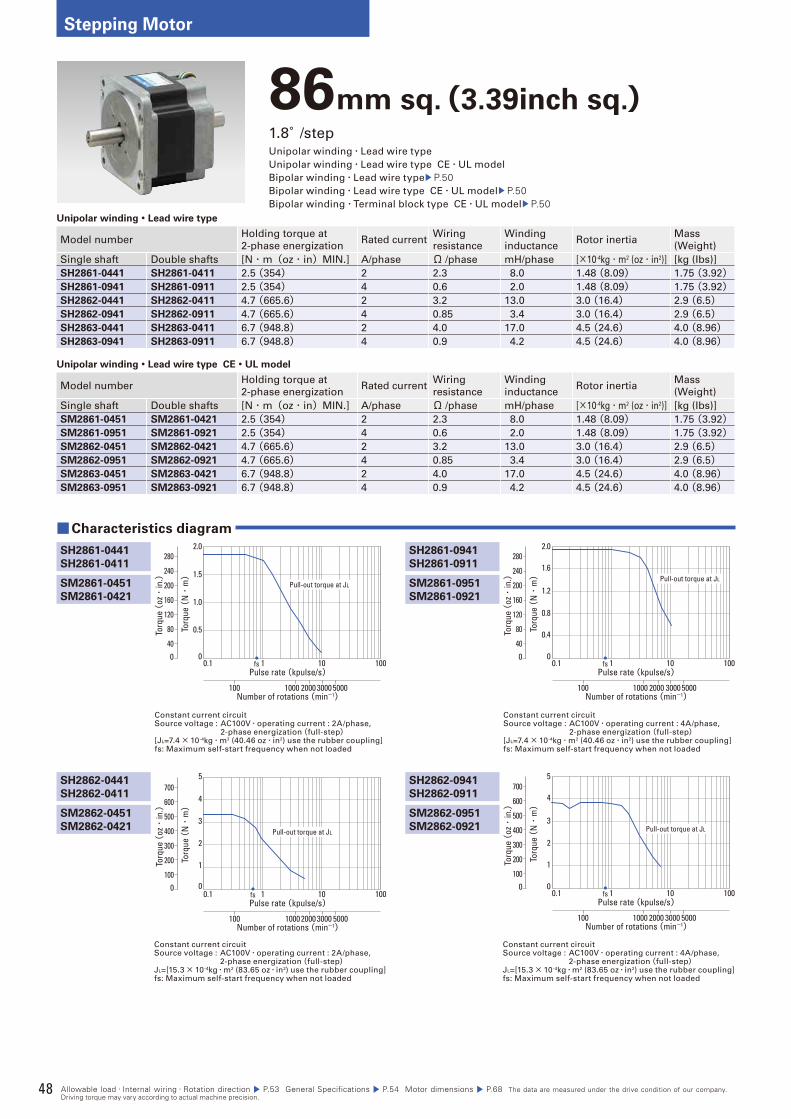
48
Stepping Motor
86mm sq.(3.39inch sq.)1.8°/stepUnipolar winding・Lead wire type
Unipolar winding・Lead wire type CE・UL model
Bipolar winding・Lead wire type P.50Bipolar winding・Lead wire type CE・UL model P.50Bipolar winding・Terminal block type CE・UL model P.50
Unipolar winding・Lead wire type
Model numberHolding torque at
2-phase energizationRated current
Wiring
resistance
Winding
inductanceRotor inertia
Mass
(Weight)
Single shaft Double shafts [N・m(oz・in)MIN.] A/phase Ω /phase mH/phase [×10-4kg・m2 (oz・in2)] [kg (Ibs)]
SH2861-0441 SH2861-0411 2.5 (354) 2 2.3 8.0 1.48 (8.09) 1.75 (3.92)SH2861-0941 SH2861-0911 2.5 (354) 4 0.6 2.0 1.48 (8.09) 1.75 (3.92)SH2862-0441 SH2862-0411 4.7 (665.6) 2 3.2 13.0 3.0 (16.4) 2.9 (6.5)SH2862-0941 SH2862-0911 4.7 (665.6) 4 0.85 3.4 3.0 (16.4) 2.9 (6.5)SH2863-0441 SH2863-0411 6.7 (948.8) 2 4.0 17.0 4.5 (24.6) 4.0 (8.96)SH2863-0941 SH2863-0911 6.7 (948.8) 4 0.9 4.2 4.5 (24.6) 4.0 (8.96)
Unipolar winding・Lead wire type CE・UL model
Model numberHolding torque at
2-phase energizationRated current
Wiring
resistance
Winding
inductanceRotor inertia
Mass
(Weight)
Single shaft Double shafts [N・m(oz・in)MIN.] A/phase Ω /phase mH/phase [×10-4kg・m2 (oz・in2)] [kg (Ibs)]
SM2861-0451 SM2861-0421 2.5 (354) 2 2.3 8.0 1.48 (8.09) 1.75 (3.92)SM2861-0951 SM2861-0921 2.5 (354) 4 0.6 2.0 1.48 (8.09) 1.75 (3.92)SM2862-0451 SM2862-0421 4.7 (665.6) 2 3.2 13.0 3.0 (16.4) 2.9 (6.5)SM2862-0951 SM2862-0921 4.7 (665.6) 4 0.85 3.4 3.0 (16.4) 2.9 (6.5)SM2863-0451 SM2863-0421 6.7 (948.8) 2 4.0 17.0 4.5 (24.6) 4.0 (8.96)SM2863-0951 SM2863-0921 6.7 (948.8) 4 0.9 4.2 4.5 (24.6) 4.0 (8.96)
Constant current circuitSource voltage : AC100V・operating current : 2A/phase, 2-phase energization(full-step)[JL=7.4× 10⁻⁴kg・m2 (40.46 oz・in2) use the rubber coupling]fs: Maximum self-start frequency when not loaded
Constant current circuitSource voltage : AC100V・operating current : 4A/phase, 2-phase energization(full-step)[JL=7.4× 10⁻⁴kg・m2 (40.46 oz・in2) use the rubber coupling]fs: Maximum self-start frequency when not loaded
SH2861-0941
SH2861-0911
■Characteristics diagram
SH2861-0441
SH2861-0411
SH2862-0441
SH2862-0411
SH2862-0941
SH2862-0911
Constant current circuitSource voltage : AC100V・operating current : 2A/phase, 2-phase energization(full-step)JL=[15.3× 10⁻⁴kg・m2 (83.65 oz・in2) use the rubber coupling]fs: Maximum self-start frequency when not loaded
Constant current circuitSource voltage : AC100V・operating current : 4A/phase, 2-phase energization(full-step)JL=[15.3× 10⁻⁴kg・m2 (83.65 oz・in2) use the rubber coupling]fs: Maximum self-start frequency when not loaded
Torq
ue (
N・
m)
2.0
1.5
1.0
0.5
00.1 1 10 100
1000 2000 3000 5000100
Pulse rate (kpulse/s)
Number of rotations (min-1)
fs0
Torq
ue (
oz・
in.)
280
200
240
160
120
80
40
Pull-out torque at JL
Torq
ue (
N・
m)2.0
1.6
1.2
0.8
0.4
00.1 1 10 100
1000 2000 3000 5000100
Pulse rate (kpulse/s)
Number of rotations (min-1)
fs0
Torq
ue (
oz・
in.)
280
200
240
160
120
80
40
Pull-out torque at JL
Torq
ue (
N・
m)
0.1 1 10 100
1000 2000 3000 5000100
Pulse rate (kpulse/s)
Number of rotations (min-1)
fs
1
2
3
4
5
00
Torq
ue (
oz・
in.)
700
600
500
400
300
200
100
Pull-out torque at JL
Torq
ue (
N・
m)
5
4
3
2
1
00.1 1 10 100
1000 2000 3000 5000100
Pulse rate (kpulse/s)
Number of rotations (min-1)
fs0
Torq
ue (
oz・
in.)
700
600
500
400
300
200
100
Pull-out torque at JL
SM2861-0951
SM2861-0921
SM2861-0451
SM2861-0421
SM2862-0451
SM2862-0421
SM2862-0951
SM2862-0921
Allowable load・Internal wiring・Rotation direction P.53 General Specifications P.54 Motor dimensions P.68 The data are measured under the drive condition of our company. Driving torque may vary according to actual machine precision.
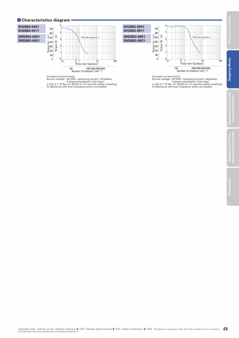
49
DC
in
pu
t se
t m
od
el
Ste
pp
ing
Mo
tor
Ste
pp
ing
mo
tors
wit
h
inte
gra
ted
dri
ve
rsS
tep
pin
g m
oto
r fo
r v
acu
um
en
vir
on
me
nt
Dim
en
sio
ns
Constant current circuitSource voltage : AC100V・operating current : 2A/phase, 2-phase energization(full-step)JL=[15.3× 10⁻⁴kg・m2 (83.65 oz・in2) use the rubber coupling]fs: Maximum self-start frequency when not loaded
Constant current circuitSource voltage : AC100V・operating current : 4A/phase, 2-phase energization(full-step)JL=[15.3× 10⁻⁴kg・m2 (83.65 oz・in2) use the rubber coupling]fs: Maximum self-start frequency when not loaded
SH2863-0941
SH2863-0911
■Characteristics diagram
SH2863-0441
SH2863-0411
Torq
ue (
N・
m)
0.1 1 10 100
1000 2000 3000 5000100
Pulse rate (kpulse/s)
Number of rotations (min-1)
fs
1
2
3
4
5
00
Torq
ue (
oz・
in.)
700
600
500
400
300
200
100
Pull-out torque at JL
Torq
ue (
N・
m)
5
4
3
2
1
00.1 1 10 100
1000 2000 3000 5000100
Pulse rate (kpulse/s)
Number of rotations (min-1)
fs0
Torq
ue (
oz・
in.)
700
600
500
400
300
200
100
Pull-out torque at JLSM2863-0951
SM2863-0921
SM2863-0451
SM2863-0421
Allowable load・Internal wiring・Rotation direction P.53 General Specifications P.54 Motor dimensions P.68 The data are measured under the drive condition of our company. Driving torque may vary according to actual machine precision.
49
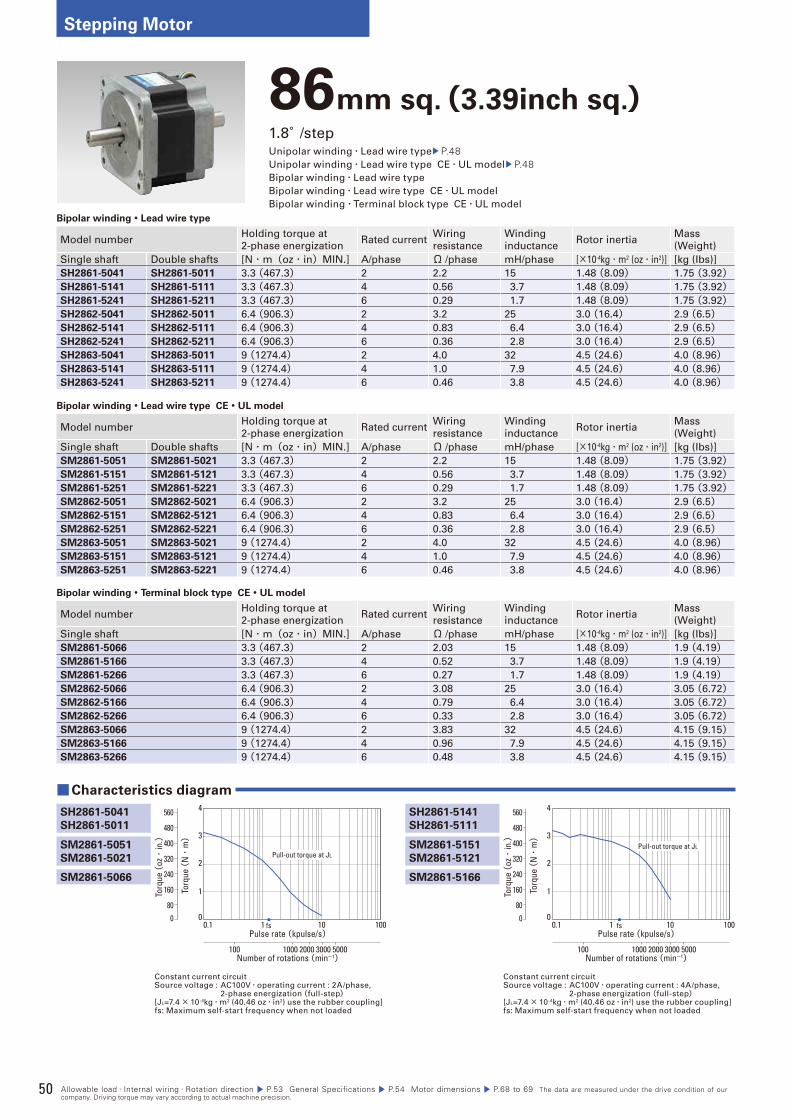
50
Stepping Motor
86mm sq.(3.39inch sq.)1.8°/stepUnipolar winding・Lead wire type P.48Unipolar winding・Lead wire type CE・UL model P.48Bipolar winding・Lead wire type
Bipolar winding・Lead wire type CE・UL model
Bipolar winding・Terminal block type CE・UL model
Bipolar winding・Lead wire type
Model numberHolding torque at
2-phase energizationRated current
Wiring
resistance
Winding
inductanceRotor inertia
Mass
(Weight)
Single shaft Double shafts [N・m(oz・in)MIN.] A/phase Ω /phase mH/phase [×10-4kg・m2 (oz・in2)] [kg (Ibs)]
SH2861-5041 SH2861-5011 3.3 (467.3) 2 2.2 15 1.48 (8.09) 1.75 (3.92)SH2861-5141 SH2861-5111 3.3 (467.3) 4 0.56 3.7 1.48 (8.09) 1.75 (3.92)SH2861-5241 SH2861-5211 3.3 (467.3) 6 0.29 1.7 1.48 (8.09) 1.75 (3.92)SH2862-5041 SH2862-5011 6.4 (906.3) 2 3.2 25 3.0 (16.4) 2.9 (6.5)SH2862-5141 SH2862-5111 6.4 (906.3) 4 0.83 6.4 3.0 (16.4) 2.9 (6.5)SH2862-5241 SH2862-5211 6.4 (906.3) 6 0.36 2.8 3.0 (16.4) 2.9 (6.5)SH2863-5041 SH2863-5011 9 (1274.4) 2 4.0 32 4.5 (24.6) 4.0 (8.96)SH2863-5141 SH2863-5111 9 (1274.4) 4 1.0 7.9 4.5 (24.6) 4.0 (8.96)SH2863-5241 SH2863-5211 9 (1274.4) 6 0.46 3.8 4.5 (24.6) 4.0 (8.96)
Bipolar winding・Lead wire type CE・UL model
Model numberHolding torque at
2-phase energizationRated current
Wiring
resistance
Winding
inductanceRotor inertia
Mass
(Weight)
Single shaft Double shafts [N・m(oz・in)MIN.] A/phase Ω /phase mH/phase [×10-4kg・m2 (oz・in2)] [kg (Ibs)]
SM2861-5051 SM2861-5021 3.3 (467.3) 2 2.2 15 1.48 (8.09) 1.75 (3.92)SM2861-5151 SM2861-5121 3.3 (467.3) 4 0.56 3.7 1.48 (8.09) 1.75 (3.92)SM2861-5251 SM2861-5221 3.3 (467.3) 6 0.29 1.7 1.48 (8.09) 1.75 (3.92)SM2862-5051 SM2862-5021 6.4 (906.3) 2 3.2 25 3.0 (16.4) 2.9 (6.5)SM2862-5151 SM2862-5121 6.4 (906.3) 4 0.83 6.4 3.0 (16.4) 2.9 (6.5)SM2862-5251 SM2862-5221 6.4 (906.3) 6 0.36 2.8 3.0 (16.4) 2.9 (6.5)SM2863-5051 SM2863-5021 9 (1274.4) 2 4.0 32 4.5 (24.6) 4.0 (8.96)SM2863-5151 SM2863-5121 9 (1274.4) 4 1.0 7.9 4.5 (24.6) 4.0 (8.96)SM2863-5251 SM2863-5221 9 (1274.4) 6 0.46 3.8 4.5 (24.6) 4.0 (8.96)
Bipolar winding・Terminal block type CE・UL model
Model numberHolding torque at
2-phase energizationRated current
Wiring
resistance
Winding
inductanceRotor inertia
Mass
(Weight)
Single shaft [N・m(oz・in)MIN.] A/phase Ω /phase mH/phase [×10-4kg・m2 (oz・in2)] [kg (Ibs)]
SM2861-5066 3.3 (467.3) 2 2.03 15 1.48 (8.09) 1.9 (4.19)SM2861-5166 3.3 (467.3) 4 0.52 3.7 1.48 (8.09) 1.9 (4.19)SM2861-5266 3.3 (467.3) 6 0.27 1.7 1.48 (8.09) 1.9 (4.19)SM2862-5066 6.4 (906.3) 2 3.08 25 3.0 (16.4) 3.05 (6.72)SM2862-5166 6.4 (906.3) 4 0.79 6.4 3.0 (16.4) 3.05 (6.72)SM2862-5266 6.4 (906.3) 6 0.33 2.8 3.0 (16.4) 3.05 (6.72)SM2863-5066 9 (1274.4) 2 3.83 32 4.5 (24.6) 4.15 (9.15)SM2863-5166 9 (1274.4) 4 0.96 7.9 4.5 (24.6) 4.15 (9.15)SM2863-5266 9 (1274.4) 6 0.48 3.8 4.5 (24.6) 4.15 (9.15)
Constant current circuitSource voltage : AC100V・operating current : 2A/phase, 2-phase energization(full-step)[JL=7.4× 10⁻⁴kg・m2 (40.46 oz・in2) use the rubber coupling]fs: Maximum self-start frequency when not loaded
Constant current circuitSource voltage : AC100V・operating current : 4A/phase, 2-phase energization(full-step)[JL=7.4× 10⁻⁴kg・m2 (40.46 oz・in2) use the rubber coupling]fs: Maximum self-start frequency when not loaded
SH2861-5141
SH2861-5111
■Characteristics diagram
SH2861-5041
SH2861-5011
Torq
ue (
N・
m)
0
1
2
3
4
Pulse rate (kpulse/s)
Number of rotations (min-1)
0.1 1 10 100
1000 2000 3000 5000100
fs
Torq
ue (
oz・
in.)
560
0
480
400
320
240
160
80
Pull-out torque at JL
Torq
ue (
N・
m)
0
1
2
3
4
Pulse rate (kpulse/s)
Number of rotations (min-1)
0.1 1 10 100
1000 2000 3000 5000100
fs
Torq
ue (
oz・
in.)
560
0
480
400
320
240
160
80
Pull-out torque at JLSM2861-5151
SM2861-5121
SM2861-5051
SM2861-5021
SM2861-5166SM2861-5066
Allowable load・Internal wiring・Rotation direction P.53 General Specifications P.54 Motor dimensions P.68 to 69 The data are measured under the drive condition of our company. Driving torque may vary according to actual machine precision.
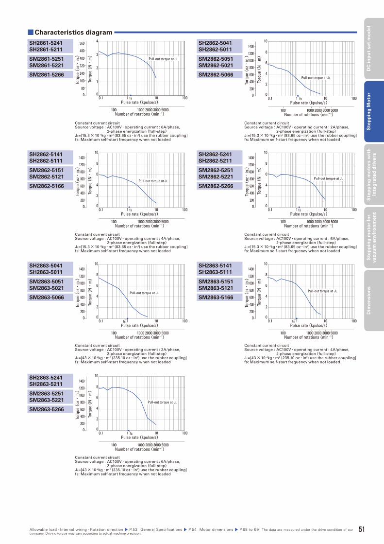
51
DC
in
pu
t se
t m
od
el
Ste
pp
ing
Mo
tor
Ste
pp
ing
mo
tors
wit
h
inte
gra
ted
dri
ve
rsS
tep
pin
g m
oto
r fo
r v
acu
um
en
vir
on
me
nt
Dim
en
sio
ns
Constant current circuitSource voltage : AC100V・operating current : 4A/phase, 2-phase energization(full-step)JL=[15.3× 10⁻⁴kg・m2 (83.65 oz・in2) use the rubber coupling]fs: Maximum self-start frequency when not loaded
Constant current circuitSource voltage : AC100V・operating current : 6A/phase, 2-phase energization(full-step)JL=[15.3× 10⁻⁴kg・m2 (83.65 oz・in2) use the rubber coupling]fs: Maximum self-start frequency when not loaded
Constant current circuitSource voltage : AC100V・operating current : 6A/phase, 2-phase energization(full-step)JL=[15.3× 10⁻⁴kg・m2 (83.65 oz・in2) use the rubber coupling]fs: Maximum self-start frequency when not loaded
Constant current circuitSource voltage : AC100V・operating current : 2A/phase, 2-phase energization(full-step)JL=[15.3× 10⁻⁴kg・m2 (83.65 oz・in2) use the rubber coupling]fs: Maximum self-start frequency when not loaded
SH2862-5241
SH2862-5211
SH2862-5041
SH2862-5011
■ Characteristics diagram
SH2862-5141
SH2862-5111
SH2861-5241
SH2861-5211
SH2863-5041
SH2863-5011
SH2863-5241
SH2863-5211
SH2863-5141
SH2863-5111
Constant current circuitSource voltage : AC100V・operating current : 2A/phase, 2-phase energization(full-step)JL=[43× 10-4kg・m2 (235.10 oz・in2) use the rubber coupling]fs: Maximum self-start frequency when not loaded
Constant current circuitSource voltage : AC100V・operating current : 6A/phase, 2-phase energization(full-step)JL=[43× 10-4kg・m2 (235.10 oz・in2) use the rubber coupling]fs: Maximum self-start frequency when not loaded
Constant current circuitSource voltage : AC100V・operating current : 4A/phase, 2-phase energization(full-step)JL=[43× 10-4kg・m2 (235.10 oz・in2) use the rubber coupling]fs: Maximum self-start frequency when not loaded
Torq
ue (
N・
m)
Pulse rate (kpulse/s)
Number of rotations (min-1)
0.1 1 10 100
1000 2000 3000 5000100
fs
2
4
6
8
10
00
Torq
ue (
oz・
in.)
1400
1200
1000
800
600
400
200
Pull-out torque at JL
Torq
ue (
N・
m)
0
1
2
3
4
Pulse rate (kpulse/s)
Number of rotations (min-1)
0.1 1 10 100
1000 2000 3000 5000100
fs
Torq
ue (
oz・
in.)
560
0
480
400
320
240
160
80
Pull-out torque at JL
Torq
ue (
N・
m)
Pulse rate (kpulse/s)
Number of rotations (min-1)
0.1 1 10 100
1000 2000 3000 5000100
fs
2
4
6
8
10
00
Torq
ue (
oz・
in.)
1400
1200
1000
800
600
400
200
Pull-out torque at JL
Torq
ue (
N・
m)
Pulse rate (kpulse/s)
Number of rotations (min-1)
0.1 1 10 100
1000 2000 3000 5000100
fs
2
4
6
8
10
00
Torq
ue (
oz・
in.)
1400
1200
1000
800
600
400
200
Pull-out torque at JL
Torq
ue (
N・
m)
Pulse rate (kpulse/s)
Number of rotations (min-1)
0.1 1 10 100
1000 2000 3000 5000100
fs
2
4
6
8
10
00
Torq
ue (
oz・
in.)
1400
1200
1000
800
600
400
200
Pull-out torque at JL
Torq
ue (
N・
m)
Pulse rate (kpulse/s)
Number of rotations (min-1)
0.1 1 10 100
1000 2000 3000 5000100
fs
2
4
6
8
10
00
Torq
ue (
oz・
in.)
1400
1200
1000
800
600
400
200
Pull-out torque at JL
Torq
ue (
N・
m)
Pulse rate (kpulse/s)
Number of rotations (min-1)
0.1 1 10 100
1000 2000 3000 5000100
fs
2
4
6
8
10
00
Torq
ue (
oz・
in.)
1400
1200
1000
800
600
400
200
Pull-out torque at JL
SM2862-5251
SM2862-5221
SM2862-5051
SM2862-5021
SM2862-5151
SM2862-5121
SM2861-5251
SM2861-5221
SM2863-5051
SM2863-5021
SM2863-5251
SM2863-5221
SM2863-5151
SM2863-5121
SM2862-5266
SM2862-5066
SM2862-5166
SM2861-5266
SM2863-5066
SM2863-5266
SM2863-5166
Allowable load・Internal wiring・Rotation direction P.53 General Specifications P.54 Motor dimensions P.68 to 69 The data are measured under the drive condition of our company. Driving torque may vary according to actual machine precision.
51
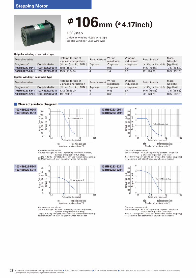
52
Stepping Motor
φ106mm (φ4.17inch)1.8°/stepUnipolar winding・Lead wire type
Bipolar winding・Lead wire type
Unipolar winding・Lead wire type
Model numberHolding torque at
2-phase energizationRated current
Wiring
resistance
Winding
inductanceRotor inertia
Mass
(Weight)
Single shaft Double shafts [N・m(oz・in)MIN.] A/phase Ω /phase mH/phase [×10-4kg・m2 (oz・in2)] [kg (Ibs)]
103H89222-0941 103H89222-0911 10.8 (1529.4) 4 0.98 6.3 14.6 (79.83) 7.5 (16.53)103H89223-0941 103H89223-0911 15.5 (2194.9) 4 1.4 9.7 22 (120.28) 10.5 (23.15)
Bipolar winding・Lead wire type
Model numberHolding torque at
2-phase energizationRated current
Wiring
resistance
Winding
inductanceRotor inertia
Mass
(Weight)
Single shaft Double shafts [N・m(oz・in)MIN.] A/phase Ω /phase mH/phase [×10-4kg・m2 (oz・in2)] [kg (Ibs)]
103H89222-5241 103H89222-5211 13.2 (1869.2) 6 0.45 5.4 14.6 (79.83) 7.5 (16.53)103H89223-5241 103H89223-5211 19 (2690.5) 6 0.63 8 22 (120.28) 10.5 (23.15)
Constant current circuitSource voltage : AC100V・operating current : 4A/phase, 2-phase energization(full-step)JL=[43× 10-4kg・m2 (235.10 oz・in2) use the rubber coupling]fs: Maximum self-start frequency when not loaded
Constant current circuitSource voltage : AC100V・operating current : 4A/phase, 2-phase energization(full-step)JL=[43× 10-4kg・m2 (235.10 oz・in2) use the rubber coupling]fs: Maximum self-start frequency when not loaded
103H89223-0941
103H89223-0911
■Characteristics diagram
103H89222-0941
103H89222-0911
103H89222-5241
103H89222-5211
103H89223-5241
103H89223-5211
Constant current circuitSource voltage : AC100V・operating current : 6A/phase, 2-phase energization(full-step)JL=[43× 10-4kg・m2 (235.10 oz・in2) use the rubber coupling]fs: Maximum self-start frequency when not loaded
Constant current circuitSource voltage : AC100V・operating current : 6A/phase, 2-phase energization(full-step)JL=[43× 10-4kg・m2 (235.10 oz・in2) use the rubber coupling]fs: Maximum self-start frequency when not loaded
Torq
ue (
N・
m)
Pulse rate (kpulse/s)
Number of rotations (min-1)
fs0.1 1 10 100
1000 2000 3000 5000100
2
4
6
8
10
00
Torq
ue (
oz・
in.)
1400
1200
1000
800
600
400
200
Pull-out torque at JL
Torq
ue (
N・
m)
Pulse rate (kpulse/s)
Number of rotations (min-1)
fs0.1 1 10 100
1000200030005000100
4
8
12
16
20
00
Torq
ue (
oz・
in.)
2400
2800
2000
1600
800
1200
400
Pull-out torque at JL
Torq
ue (
N・
m)
Pulse rate (kpulse/s)
Number of rotations (min-1)
0.1 1 10 100
1000 2000 3000 5000100
fs
4
8
12
16
20
00
Torq
ue (
oz・
in.)
280
200
240
160
120
80
40
Pull-out torque at JL
Torq
ue (
N・
m)
Pulse rate (kpulse/s)
Number of rotations (min-1)
0.1 1 10 100
1000 2000 3000 5000100
fs
4
8
12
16
20
00
Torq
ue (
oz・
in.)
2400
2800
2000
1600
800
1200
400
Pull-out torque at JL
Allowable load・Internal wiring・Rotation direction P.53 General Specifications P.54 Motor dimensions P.69 The data are measured under the drive condition of our company. Driving torque may vary according to actual machine precision.
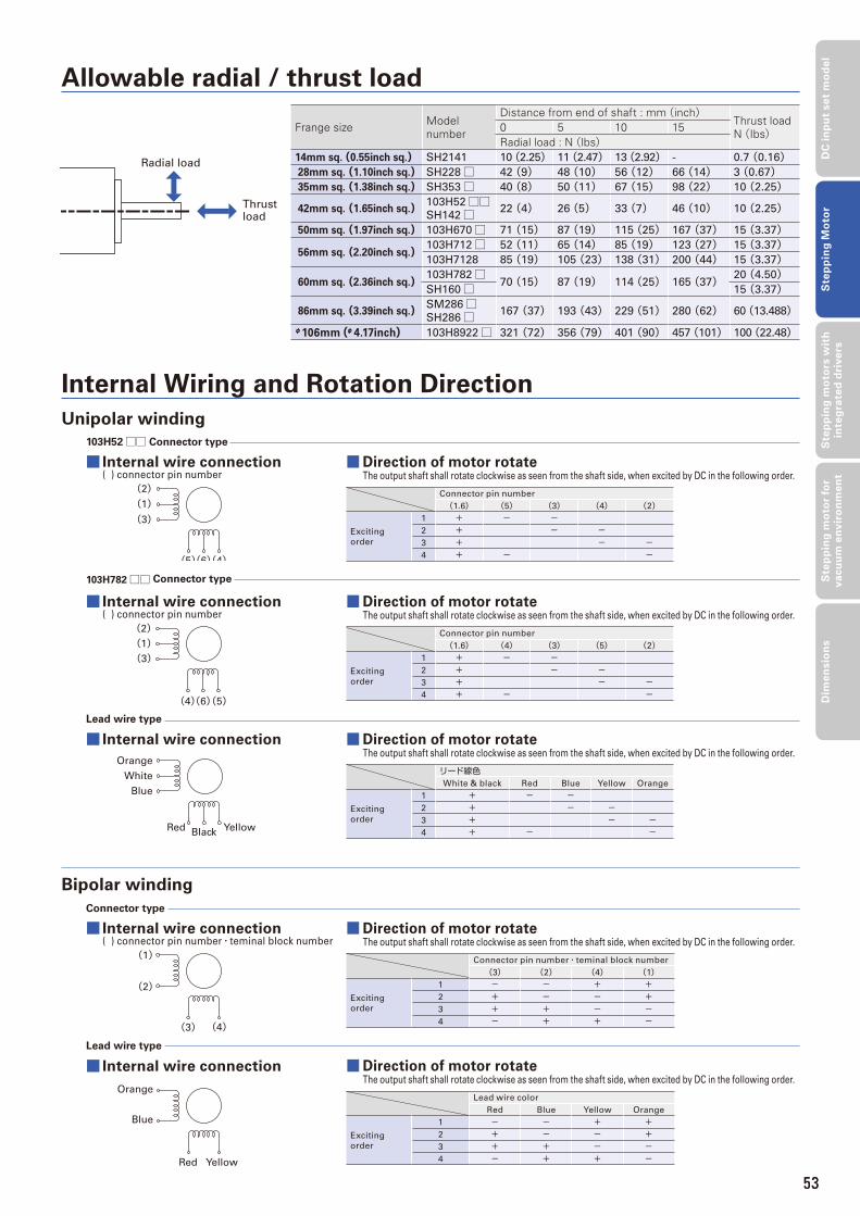
53
DC
in
pu
t se
t m
od
el
Ste
pp
ing
Mo
tor
Ste
pp
ing
mo
tors
wit
h
inte
gra
ted
dri
ve
rsS
tep
pin
g m
oto
r fo
r v
acu
um
en
vir
on
me
nt
Dim
en
sio
ns
Frange size Model number
Distance from end of shaft : mm(inch)Thrust loadN(Ibs)0 5 10 15
Radial load : N(lbs)14mm sq. (0.55inch sq.) SH2141 10 (2.25) 11 (2.47) 13 (2.92) - 0.7 (0.16) 28mm sq.(1.10inch sq.) SH228□ 42 (9) 48 (10) 56 (12) 66 (14) 3 (0.67) 35mm sq.(1.38inch sq.) SH353□ 40 (8) 50 (11) 67 (15) 98 (22) 10 (2.25)
42mm sq.(1.65inch sq.) 103H52□□SH142□ 22 (4) 26 (5) 33 (7) 46 (10) 10 (2.25)
50mm sq.(1.97inch sq.) 103H670□ 71 (15) 87 (19) 115 (25) 167 (37) 15 (3.37)
56mm sq.(2.20inch sq.)103H712□ 52 (11) 65 (14) 85 (19) 123 (27) 15 (3.37)103H7128 85 (19) 105 (23) 138 (31) 200 (44) 15 (3.37)
60mm sq.(2.36inch sq.)103H782□
70 (15) 87 (19) 114 (25) 165 (37) 20 (4.50)SH160□ 15 (3.37)
86mm sq.(3.39inch sq.) SM286□SH286□ 167 (37) 193 (43) 229 (51) 280 (62) 60 (13.488)
φ106mm(φ4.17inch) 103H8922□ 321 (72) 356 (79) 401 (90) 457 (101) 100 (22.48)
Radial load
Thrust load
Allowable radial / thrust load
Internal Wiring and Rotation Direction
(2)(1)(3)
(5)(6)(4)
103H52□□ Connector type
Connector type
(2)(1)(3)
(4)(6)(5)
103H782□□ Connector type
Orange
White
Blue
Red Black Yellow
Lead wire type
Lead wire type
Bipolar winding
Unipolar winding
■ Internal wire connection ( ) connector pin number
■ Internal wire connection ( ) connector pin number・teminal block number
■ Internal wire connection ( ) connector pin number
■ Internal wire connection
■ Internal wire connection
■Direction of motor rotateThe output shaft shall rotate clockwise as seen from the shaft side, when excited by DC in the following order.
Connector pin number
(1.6) (5) (3) (4) (2)
Exciting
order
1 + - -2 + - -3 + - -4 + - -
■Direction of motor rotateThe output shaft shall rotate clockwise as seen from the shaft side, when excited by DC in the following order.
Connector pin number
(1.6) (4) (3) (5) (2)
Exciting
order
1 + - -2 + - -3 + - -4 + - -
■Direction of motor rotateThe output shaft shall rotate clockwise as seen from the shaft side, when excited by DC in the following order.
リード線色White & black Red Blue Yellow Orange
Exciting
order
1 + - -2 + - -3 + - -4 + - -
■Direction of motor rotateThe output shaft shall rotate clockwise as seen from the shaft side, when excited by DC in the following order.
Connector pin number・teminal block number
(3) (2) (4) (1)
Exciting
order
1 - - + +2 + - - +3 + + - -4 - + + -
■Direction of motor rotateThe output shaft shall rotate clockwise as seen from the shaft side, when excited by DC in the following order.
Lead wire color
Red Blue Yellow Orange
Exciting
order
1 - - + +2 + - - +3 + + - -4 - + + -
Orange
Blue
Red Yellow
(1)
(2)
(3) (4)
53
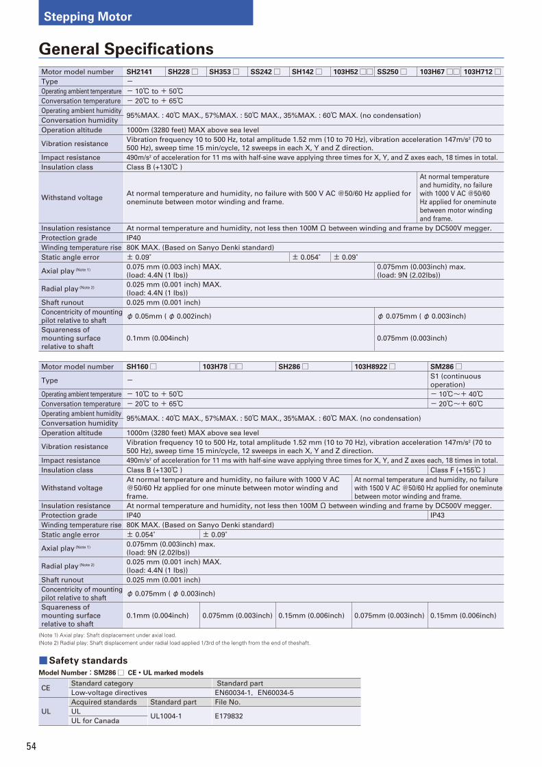
54
Stepping Motor
General Specifi cations
Motor model number SH2141 SH228□ SH353□ SS242□ SH142□ 103H52□□ SS250□ 103H67□□ 103H712□Type -Operating ambient temperature - 10℃ to + 50℃Conversation temperature - 20℃ to + 65℃Operating ambient humidity
95%MAX. : 40℃MAX., 57%MAX. : 50℃MAX., 35%MAX. : 60℃MAX. (no condensation)Conversation humidity
Operation altitude 1000m (3280 feet) MAX above sea level
Vibration resistanceVibration frequency 10 to 500 Hz, total amplitude 1.52 mm (10 to 70 Hz), vibration acceleration 147m/s2 (70 to
500 Hz), sweep time 15 min/cycle, 12 sweeps in each X, Y and Z direction.
Impact resistance 490m/s2 of acceleration for 11 ms with half-sine wave applying three times for X, Y, and Z axes each, 18 times in total.
Insulation class Class B (+130℃ )
Withstand voltageAt normal temperature and humidity, no failure with 500 V AC @50/60 Hz applied for
oneminute between motor winding and frame.
At normal temperature
and humidity, no failure
with 1000 V AC @50/60
Hz applied for oneminute
between motor winding
and frame.
Insulation resistance At normal temperature and humidity, not less then 100MΩ between winding and frame by DC500V megger.
Protection grade IP40
Winding temperature rise 80K MAX. (Based on Sanyo Denki standard)
Static angle error ± 0.09° ± 0.054° ± 0.09°
Axial play (Note 1)0.075 mm (0.003 inch) MAX.
(load: 4.4N (1 lbs))
0.075mm (0.003inch) max.
(load: 9N (2.02lbs))
Radial play (Note 2)0.025 mm (0.001 inch) MAX.
(load: 4.4N (1 lbs))
Shaft runout 0.025 mm (0.001 inch)
Concentricity of mounting
pilot relative to shaftφ 0.05mm (φ 0.002inch) φ 0.075mm (φ 0.003inch)
Squareness of
mounting surface
relative to shaft
0.1mm (0.004inch) 0.075mm (0.003inch)
Motor model number SH160□ 103H78□□ SH286□ 103H8922□ SM286□
Type - S1 (continuous
operation)
Operating ambient temperature - 10℃ to + 50℃ - 10℃~+ 40℃Conversation temperature - 20℃ to + 65℃ - 20℃~+ 60℃Operating ambient humidity
95%MAX. : 40℃MAX., 57%MAX. : 50℃MAX., 35%MAX. : 60℃MAX. (no condensation)Conversation humidity
Operation altitude 1000m (3280 feet) MAX above sea level
Vibration resistanceVibration frequency 10 to 500 Hz, total amplitude 1.52 mm (10 to 70 Hz), vibration acceleration 147m/s2 (70 to
500 Hz), sweep time 15 min/cycle, 12 sweeps in each X, Y and Z direction.
Impact resistance 490m/s2 of acceleration for 11 ms with half-sine wave applying three times for X, Y, and Z axes each, 18 times in total.
Insulation class Class B (+130℃ ) Class F (+155℃ )
Withstand voltage
At normal temperature and humidity, no failure with 1000 V AC
@50/60 Hz applied for one minute between motor winding and
frame.
At normal temperature and humidity, no failure
with 1500 V AC @50/60 Hz applied for oneminute
between motor winding and frame.
Insulation resistance At normal temperature and humidity, not less then 100MΩ between winding and frame by DC500V megger.
Protection grade IP40 IP43
Winding temperature rise 80K MAX. (Based on Sanyo Denki standard)
Static angle error ± 0.054° ± 0.09°
Axial play (Note 1)0.075mm (0.003inch) max.
(load: 9N (2.02lbs))
Radial play (Note 2)0.025 mm (0.001 inch) MAX.
(load: 4.4N (1 lbs))
Shaft runout 0.025 mm (0.001 inch)
Concentricity of mounting
pilot relative to shaftφ 0.075mm (φ 0.003inch)
Squareness of
mounting surface
relative to shaft
0.1mm (0.004inch) 0.075mm (0.003inch) 0.15mm (0.006inch) 0.075mm (0.003inch) 0.15mm (0.006inch)
(Note 1) Axial play: Shaft displacement under axial load.(Note 2) Radial play: Shaft displacement under radial load applied 1/3rd of the length from the end of theshaft.
■Safety standards
Model Number‥SM286□ CE・UL marked models
CEStandard category Standard part
Low-voltage directives EN60034-1,EN60034-5
UL
Acquired standards Standard part File No.
ULUL1004-1 E179832
UL for Canada
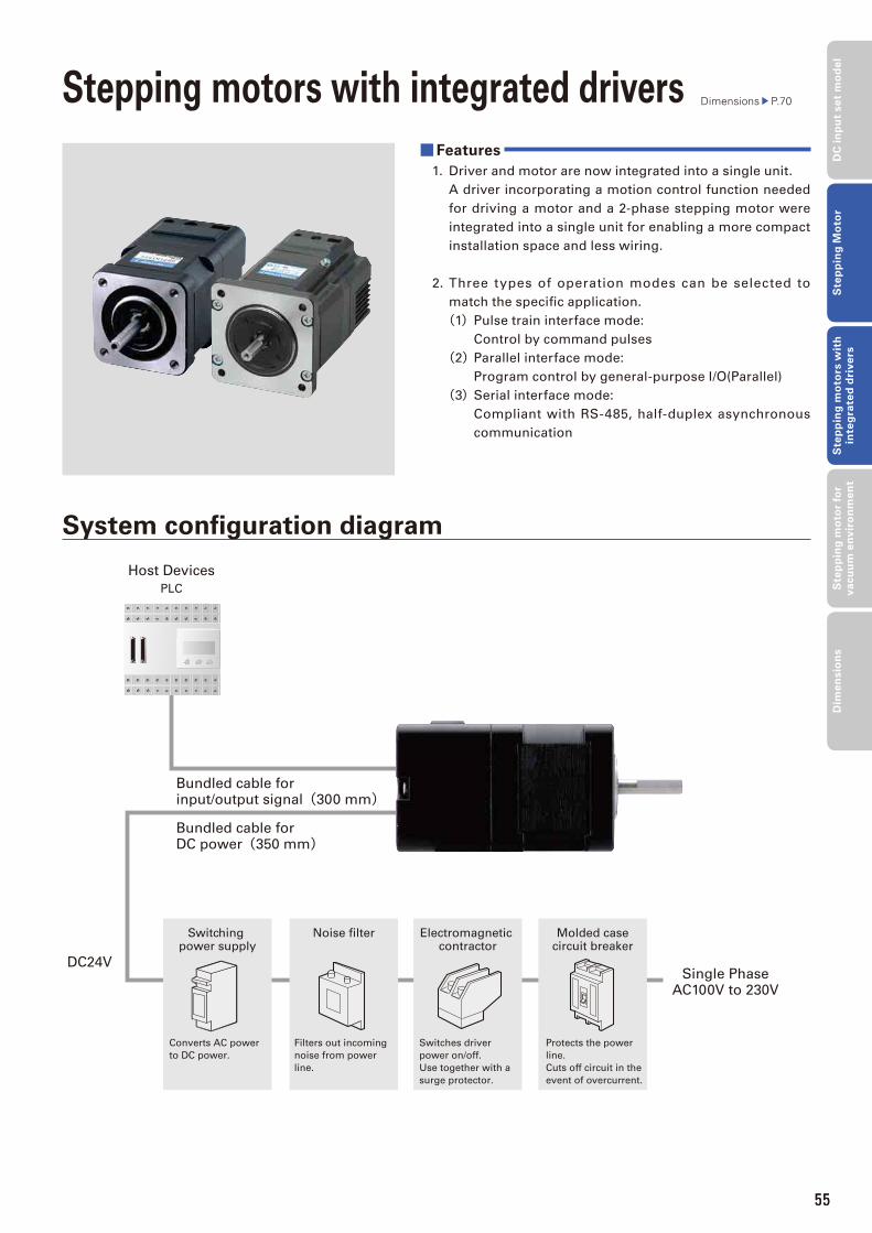
55
Stepping motors with integrated drivers Dimensions P.70
■Features
1. Driver and motor are now integrated into a single unit.
A driver incorporating a motion control function needed
for driving a motor and a 2-phase stepping motor were
integrated into a single unit for enabling a more compact
installation space and less wiring.
2. Three types of operation modes can be selected to
match the specifi c application.
(1) Pulse train interface mode:
Control by command pulses
(2) Parallel interface mode:
Program control by general-purpose I/O(Parallel)
(3) Serial interface mode:
Compliant with RS-485, half-duplex asynchronous
communication
System confi guration diagram
Host Devices
PLC
Single PhaseAC100V to 230V
DC24V
Bundled cable forinput/output signal(300 mm)
Bundled cable forDC power(350 mm)
Noise filterSwitching power supply
Electromagnetic contractor
Molded casecircuit breaker
Protects the power
line.
Cuts off circuit in the
event of overcurrent.
Switches driver
power on/off.
Use together with a
surge protector.
Filters out incoming
noise from power
line.
Converts AC power
to DC power.
55
DC
in
pu
t se
t m
od
el
Ste
pp
ing
Mo
tor
Ste
pp
ing
mo
tors
wit
h
inte
gra
ted
dri
ve
rsS
tep
pin
g m
oto
r fo
r v
acu
um
en
vir
on
me
nt
Dim
en
sio
ns
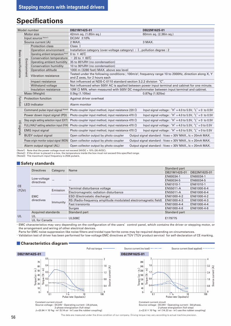
56
Stepping motors with integrated drivers
The data are measured under the drive condition of our company. Driving torque may vary according to actual machine precision.
Specifi cations
Model number DB21M142S-01 DB22M162S-01
Ba
sic
sp
ecifi c
atio
ns
Motor size 42mm sq. (1.65in sq.) 60mm sq. (2.36in sq.)
Input source (Note1) DC24V ±10%Source current (A) 2 MAX. 3 MAX.
En
viro
nm
en
t
Protection class Class ⅠOperation environment Installation category (over-voltage category) : Ⅰ, pollution degree : 2
Operating ambient temperature (Note2) 0 to + 40℃Conservation temperature - 20 to + 60℃Operating ambient humidity 35 to 85%RH (no condensation)
Conservation humidity 10 to 90%RH (no condensation)
Operation altitude 1000 m (3280 feet) MAX. above sea level
Vibration resistanceTested under the following conditions ; 100m/s2, frequency range 10 to 2000Hz, direction along X, Y
and Z axes, for 2 hours each
Impact resistance Not infl uenced at NDS-C-0110 standard section 3.2.2 division“C”.Withstand voltage Not infl uenced when 500V AC is applied between power input terminal and cabinet for one minute.
Insulation resistance 10M Ω MIN. when measured with 500V DC megohmmeter between input terminal and cabinet.
Mass (Weight) 0.5kg (1.10lbs) 0.87kg (1.92lbs)
Fun
ction
Protection function Against driver overheat
LED indicator Alarm monitor
I/O s
ign
als
Command pulse input signal (Note3) Photo coupler input method, input resistance 220Ω Input signal voltage : “H” = 4.0 to 5.5V, “L” = 0 to 0.5V
Power down input signal (PD) Photo coupler input method, input resistance 470Ω Input signal voltage : “H” = 4.0 to 5.5V, “L” = 0 to 0.5V
Step angle setting selection input (EXT) Photo coupler input method, input resistance 470Ω Input signal voltage : “H” = 4.0 to 5.5V, “L” = 0 to 0.5V
FULL/HALF setting selection input (F/H) Photo coupler input method, input resistance 470Ω Input signal voltage : “H” = 4.0 to 5.5V, “L” = 0 to 0.5V
EMG input signal Photo coupler input method, input resistance 470Ω Input signal voltage : “H” = 4.0 to 5.5V, “L” = 0 to 0.5V
BUSY output signal Open collector output by photo coupler Output signal standard : Vceo = 30V MAX., Ic = 20mA MAX.
Phase origin monitor output signal (MON) Open collector output by photo coupler Output signal standard : Vceo = 30V MAX., Ic = 20mA MAX.
Alarm output signal (AL) Open collector output by photo coupler Output signal standard : Vceo = 30V MAX., Ic = 20mA MAX.
(Note1) Note that the power voltage must not exceed 24VDC + 10% (26.4VDC).
(Note2) If the driver is placed in a box, the temperature inside the box must not exceed this specifi ed range.
(Note3) The maximum input frequency is 250k pulse/s.
■Safety standards
CE
(TÜV)
Directives Category NameStandard part
DB21M142S-01 DB22M162S-01
Low-voltage
directives- -
EN60034-1 EN60034-1
EN60034-5 EN60034-5
EN61010-1 EN61010-1
EMC
directives
EmissionTerminal disturbance voltage EN55011-A EN61000-6-4
Electromagnetic radiation disturbance EN55011-A EN61000-6-4
Immunity
ESD (Electrostatic discharge) EN61000-4-2 EN61000-4-2
RS (Radio-frequency amplitude modulated electromagnetic fi eld) EN61000-4-3 EN61000-4-3
Fast transionts EN61000-4-4 EN61000-4-4
Surges EN61000-4-6 EN61000-4-6
UL
Acquired standards Standard part Standard part
ULUL508C E179775
UL for Canada
・ EMC characteristics may vary depending on the confi guration of the users’control panel, which contains the driver or stepping motor, or
the arrangement and wiring of other electrical devices.
Parts for EMC noise suppression like noise fi lters and troidal type ferrite cores may be required depending on circumstances.
・ Validation test of driver has been performed for low-voltage EMC directives at TÜV(TÜV product service)for self-declaration of CE marking.
Constant current circuit
Source voltage : DC24V・Operating current : 2A/phase,
2-phase energization (full-step)
JL=[0.94× 10⁻⁴kg・m2 (5.14 oz・in2) use the rubber coupling]
Constant current circuit
Source voltage : DC24V・Operating current : 3A/phase,
2-phase energization (full-step)
JL=[2.6× 10⁻⁴kg・m2 (14.22 oz・in2) use the rubber coupling]
DB22M162S-01
■ Characteristics diagram
DB21M142S-01
Torq
ue (
N・
m)
0
0.4
0.8
1.2
1.6
2
0
0.1
0.2
0.3
0.4
0.5
0.1 1 10 100Pulse rate (kpulse/s)
Sour
ce c
urre
nt (A)
fs0
Torq
ue(oz・
in.)
70
60
50
40
30
20
10
Torq
ue (
N・
m)
0
0.8
1.6
2.4
3.2
4
0
0.4
0.8
1.2
1.6
2
0.1 1 10 100Pulse rate (kpulse/s)
Sour
ce c
urre
nt (A)
fs0
Torq
ue (
oz・
in.)
280
200
240
160
120
80
40
Pull-out torque Source current (no load) Source current (load applied)
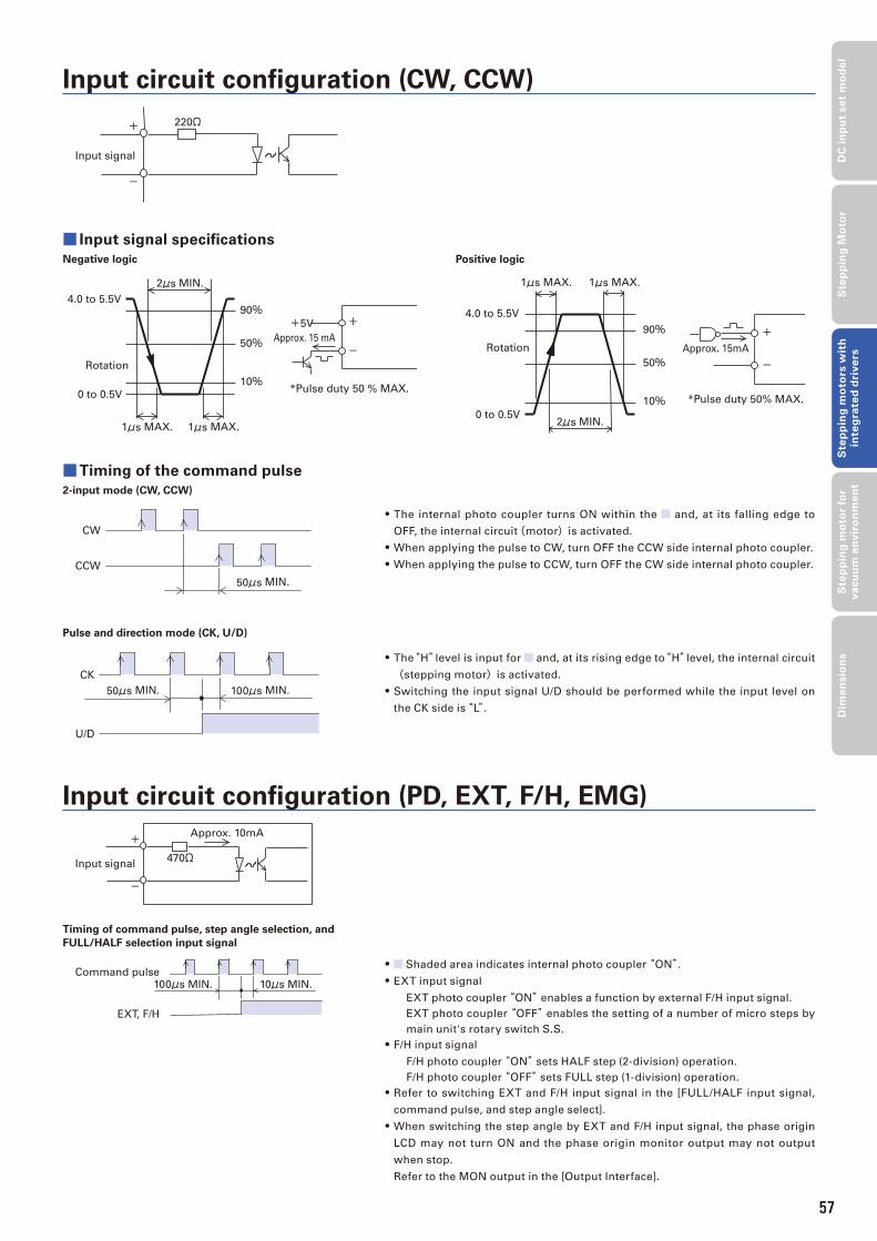
57
■Timing of the command pulse
2-input mode (CW, CCW)
Input circuit confi guration (CW, CCW)
Input circuit confi guration (PD, EXT, F/H, EMG)
■ Input signal specifi cations
Negative logic
• The internal photo coupler turns ON within the and, at its falling edge to
OFF, the internal circuit(motor)is activated.
• When applying the pulse to CW, turn OFF the CCW side internal photo coupler.
• When applying the pulse to CCW, turn OFF the CW side internal photo coupler.
• The“H”level is input for and, at its rising edge to“H”level, the internal circuit
(stepping motor)is activated.
• Switching the input signal U/D should be performed while the input level on
the CK side is“L”.
Input signal
220Ω+
-
Rotation
*Pulse duty 50 % MAX.
+5V
90%
2μs MIN.
1μs MAX. 1μs MAX.
50%
10%
Approx. 15 mA
+
-
0 to 0.5V
4.0 to 5.5V
Pulse and direction mode (CK, U/D)
Positive logic
2μs MIN.
1μs MAX. 1μs MAX.
90%
50%
10% *Pulse duty 50% MAX.
Approx. 15mARotation
+
-
0 to 0.5V
4.0 to 5.5V
50μs MIN.
CW
CCW
100μs MIN.50μs MIN.
CK
U/D
• Shaded area indicates internal photo coupler “ON”.• EXT input signal
EXT photo coupler “ON” enables a function by external F/H input signal.
EXT photo coupler “OFF” enables the setting of a number of micro steps by
main unit's rotary switch S.S.
• F/H input signal
F/H photo coupler “ON” sets HALF step (2-division) operation.
F/H photo coupler “OFF” sets FULL step (1-division) operation.
• Refer to switching EXT and F/H input signal in the [FULL/HALF input signal,
command pulse, and step angle select].
• When switching the step angle by EXT and F/H input signal, the phase origin
LCD may not turn ON and the phase origin monitor output may not output
when stop.
Refer to the MON output in the [Output Interface].
Timing of command pulse, step angle selection, and
FULL/HALF selection input signal
Input signal470Ω
Approx. 10mA+
-
Command pulse
EXT, F/H
10μs MIN.100μs MIN.
57
DC
in
pu
t se
t m
od
el
Ste
pp
ing
Mo
tor
Ste
pp
ing
mo
tors
wit
h
inte
gra
ted
dri
ve
rsS
tep
pin
g m
oto
r fo
r v
acu
um
en
vir
on
me
nt
Dim
en
sio
ns
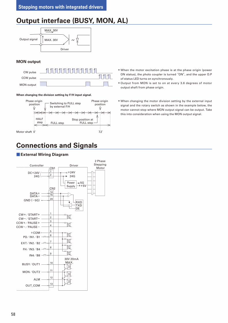
58
Stepping motors with integrated drivers
Output interface (BUSY, MON, AL)
Connections and Signals
MON output
• When the motor excitation phase is at the phase origin (power
ON status), the photo coupler is turned “ON”, and the upper D.P
of status LED turns on synchronously.
• Output from MON is set to on at every 3.6 degrees of motor
output shaft from phase origin.
Phase origin
position
Phase origin
positionSwitching to FULL step
by external F/H
FULL step
HALF
stepStop position at
FULL step
7.2˚Motor shaft 0˚
When changing the division setting by F/H input signal.
• When changing the motor division setting by the external input
signal and the rotary switch as shown in the example below, the
motor cannot stop where MON output signal can be output. Take
this into consideration when using the MON output signal.
Driver
MAX. 30V
MAX. 30V
Output signal
CW pulse
CCW pulse
MON output
DC+24V
24G
+24V
24G
5G+5V
RXDTXDDE
1
2
3
4
5
6
7
8
9
10
11
12
13
CN1
14
1
2
15
+COM
PD/IN1/B1
EXT/IN2/B2
FH/IN3/B4
IN4/B8
BUSY/OUT1
MON/OUT2
ALM
OUT_COM
DATA+DATA-
GND(-5G) 20
CN2
Driver
30V 20mA
MAX.
2 Phase
Stepping
MotorController
Power
Supply
CW+/START+CW-/START-
CCW+/PAUSE+CCW-/PAUSE-
■External Wiring Diagram
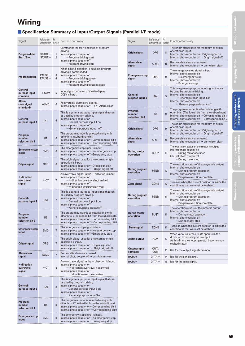
59
Signal ReferenceDesignation
PinNumber Function Summary
Program drive
Start/Stop
START+START-
1
2
Commands the start and stop of program
driving.
Internal photo coupler on
…Program driving start
Internal photo coupler off
…Program driving stop
Program pause PAUSE+PAUSE-
3
4
When START signal on, a pause in program
driving is commanded.
Internal photo coupler on
…Program driving pause
Internal photo coupler off
…Program driving pause release
General-
purpose input
common
+ COM 5Input signal common of the 6 to 9 pins
DC5V is input.
Alarm
clear signal
(standard)
ALMC 6Recoverable alarms are cleared.
Internal photo coupler off→ on…Alarm clear
General-
purpose input 1 IN1 6
This is a general-purpose input signal that can
be used by program driving.
Internal photo coupler on
…General purpose input 1 on
Internal photo coupler off
… General purpose input 1 off
Program
number
selection bit 1
B1 6
The program number is selected along with
other bits. (Subordinate bit) Internal photo coupler on…Corresponding bit 1
Internal photo coupler off… Corresponding bit 0
Emergency stop
input EMG 6
The emergency stop signal is input.
Internal photo coupler on…No emergency stop
Internal photo coupler off…Emergency stop
Origin signal ORG 6
The origin signal used for the return to origin
operation is input.
Internal photo coupler on…Origin signal on
Internal photo coupler off … Origin signal off
+ direction
overtravel
signal
+OT 7
An overtravel signal in the + direction is input.
Internal photo coupler on
…+ direction overtravel not arrived
Internal photo coupler off
…+ direction overtravel arrived
General-
purpose input 2 IN2 7
This is a general-purpose input signal that can
be used by program driving.
Internal photo coupler on
…General purpose input 2 on
Internal photo coupler off
… General purpose input 2 off
Program
number
selection bit 2
B2 7
The program number is selected along with
other bits. (The second bit from the subordinate) Internal photo coupler on…Corresponding bit 1
Internal photo coupler off… Corresponding bit 0
Emergency stop
input EMG 7
The emergency stop signal is input.
Internal photo coupler on…No emergency stop
Internal photo coupler off…Emergency stop
Origin signal ORG 7
The origin signal used for the return to origin
operation is input.
Internal photo coupler on…Origin signal on
Internal photo coupler off … Origin signal off
Alarm clear
signal ALMC 7
Recoverable alarms are cleared.
Internal photo coupler off→ on…Alarm clear
- direction
overtravel
signal
-OT 8
An overtravel signal in the - direction is input.
Internal photo coupler on
… - direction overtravel not arrived
Internal photo coupler off
… - direction overtravel arrived
General-
purpose input 3 IN3 8
This is a general-purpose input signal that can
be used by program driving.
Internal photo coupler on
…General purpose input 3 on
Internal photo coupler off
… General purpose input 3 off
Program
number
selection bit 4
B4 8
The program number is selected along with
other bits. (The third bit from the subordinate) Internal photo coupler on…Corresponding bit 1
Internal photo coupler off… Corresponding bit 0
Emergency stop
input EMG 8
The emergency stop signal is input.
Internal photo coupler on…No emergency stop
Internal photo coupler off…Emergency stop
Signal ReferenceDesignation
PinNumber Function Summary
Origin signal ORG 8
The origin signal used for the return to origin
operation is input.
Internal photo coupler on…Origin signal on
Internal photo coupler off … Origin signal off
Alarm clear
signal ALMC 8
Recoverable alarms are cleared.
Internal photo coupler off→ on…Alarm clear
Emergency stop
signal EMG 9
The emergency stop signal is input.
Internal photo coupler on
…No emergency stop
Internal photo coupler off
…Emergency stop
General-
purpose input 4 IN4 9
This is a general-purpose input signal that can
be used by program driving.
Internal photo coupler on
…General purpose input 4 on
Internal photo coupler off
… General purpose input 4 off
Program
number
selection bit 8
B8 9
The program number is selected along with
other bits. (The fourth bit from the subordinate) Internal photo coupler on … Corresponding bit 1
Internal photo coupler off … Corresponding bit 0
Origin signal ORG 9
The origin signal used for the return to origin
operation is input.
Internal photo coupler on…Origin signal on
Internal photo coupler off … Origin signal off
Alarm clear
signal ALMC 9
Recoverable alarms are cleared.
Internal photo coupler off→ on…Alarm clear
During motor
operation BUSY 10
The operation status of the motor is output.
Internal photo coupler on
…During motor operation
Internal photo coupler off
…During motor stop
During program
execution PEND 10
The execution status of the program is output.
Internal photo coupler on
…During program execution
Internal photo coupler off
…Program execution complete
Zone signal ZONE 10Turns on when the current position is inside the
coordinates that were set beforehand.
During program
execution PEND 11
The execution status of the program is output.
Internal photo coupler on
…During program execution
Internal photo coupler off
…Program execution complete
During motor
operation BUSY 11
The operation status of the motor is output.
Internal photo coupler on
…During motor operation
Internal photo coupler off
…During motor stop
Zone signal ZONE 11Turns on when the current position is inside the
coordinates that were set beforehand.
Alarm output ALM 12
When various alarm circuits operate in the
driver, an external signal is output.
At this time, the stepping motor becomes non
excited status.
Output signal
common
OUT_
COM13 It is for the output signal common.
DATA+ DATA+ 14 It is for the serial signal.
DATA- DATA- 15 It is for the serial signal.
Wiring
■Specifi cation Summary of Input/Output Signals (Parallel I/F mode)
59
DC
in
pu
t se
t m
od
el
Ste
pp
ing
Mo
tor
Ste
pp
ing
mo
tors
wit
h
inte
gra
ted
dri
ve
rsS
tep
pin
g m
oto
r fo
r v
acu
um
en
vir
on
me
nt
Dim
en
sio
ns
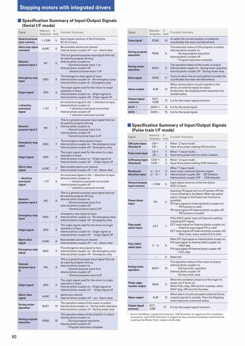
60
Stepping motors with integrated drivers
Signal ReferenceDesignation
PinNumber Function Summary
CW pulse input
(Standard)
CW+CW-
1
2
When “2 input mode”,Input drive pulse rotating CW direction.
Pulse train inputCK+CK-
1
2
When “1 input mode”,Input drive pulse train for motor rotation.
CCW pulse input
(Standard)
CCW+CCW-
3
4
When “2 input mode”,Input drive pulse rotating CCW direction.
Rotational
direction input
U/ D+U/ D-
3
4
When “1 input mode”,Input motor rotational direction signal.
Internal photo coupler ON … CW direction
Internal photo coupler OFF … CCW direction
General-purpose
input common+ COM 5
Input signal common of the 6 to 9 pins
DC5V is input.
Power down
inputPD 6
Inputting PD signal will cut off (power off) the
current fl owing to the Motor (With dip switch
select, change to the Power low function is
possible).
PD input signal on (internal photo coupler on)
… PD function is valid.
PD input signal off (internal photo coupler off)
… PD function is invalid.
Step angle
select inputEXT 7
FULL/HALF select input will become valid by
inputting EXT signal.
EXT input signal on (internal photo coupler on)
… External input signal F/H is valid
EXT input signal off (internal photo coupler off)
… Main body rotary switch S.S is valid
FULL/HALF
select inputF/ H 8
When EXT input signal on (internal photo coupler on),
F/H input signal on (internal photo coupler on)
… HALF step
F/H input signal off (internal photo coupler off)
… FULL step
9 Reserved
During motor
operationBUSY 10
The operation status of the motor is output.
Internal photo coupler on
…During motor operation
Internal photo coupler off
…During motor stop
Phase origin
monitor outputMON 11
When the excitation phase is at the origin (in
power on) it turns on.
When FULL step, ON once for 4 pulses, when
HALF step, ON once for 8 pulses.
Alarm output ALM 12
When alarm circuits actuated inside the Driver,
outputs signals to outside. Then the Stepping
motor becomes unexcited status.
Output signal
common
OUT_
COM13 It is for the output signal common.
* As for the Motor rotational direction, CW direction is regard as the clockwise
revolution, and CCW direction is regard as the counterclockwise revolution by
viewing the Motor from output shaft side.
Signal ReferenceDesignation
PinNumber Function Summary
General-purpose
input common+ COM 5
Input signal common of the 6 to 9 pins
DC 5V is input.
Alarm clear signal
(standard)ALMC 6
Recoverable alarms are cleared.
Internal photo coupler off→ on…Alarm clear
General-
purpose input 1IN1 6
This is a general-purpose input signal that can
be used by program driving.
Internal photo coupler on
…General purpose input 1 on
Internal photo coupler off
… General purpose input 1 off
Emergency stop
inputEMG 6
The emergency stop signal is input.
Internal photo coupler on…No emergency stop
Internal photo coupler of…Emergency stop
Origin signal ORG 6
The origin signal used for the return to origin
operation is input.
Internal photo coupler on…Origin signal on
Internal photo coupler off…Origin signal off
+ direction
overtravel
signal
+OT 7
An overtravel signal in the + direction is input.
Internal photo coupler on
… + direction overtravel not arrived
Internal photo coupler off
… + direction overtravel arrived
General-
purpose input 2IN2 7
This is a general-purpose input signal that can
be used by program driving.
Internal photo coupler on
…General purpose input 2 on
Internal photo coupler off
…General purpose input 2 off
Emergency stop
inputEMG 7
The emergency stop signal is input.
Internal photo coupler on…No emergency stop
Internal photo coupler off…Emergency stop
Origin signal ORG 7
The origin signal used for the return to origin
operation is input.
Internal photo coupler on…Origin signal on
Internal photo coupler off … Origin signal off
Alarm clear
signalALMC 7
Recoverable alarms are cleared.
Internal photo coupler off→ on…Alarm clear
- direction
overtravel
signal
-OT 8
An overtravel signal in the - direction is input.
Internal photo coupler on
… - direction overtravel not arrived
Internal photo coupler off
… - direction overtravel arrived
General-
purpose input 3IN3 8
This is a general-purpose input signal that can
be used by program driving.
Internal photo coupler on
…General purpose input 3 on
Internal photo coupler off
… General purpose input 3 off
Emergency stop
inputEMG 8
emergency stop signal is input.
Internal photo coupler on…No emergency stop
Internal photo coupler off…Emergency stop
Origin signal ORG 8
The origin signal used for the return to origin
operation is input.
Internal photo coupler on…Origin signal on
Internal photo coupler off … Origin signal off
Alarm clear
signalALMC 8
Recoverable alarms are cleared.
Internal photo coupler off→ on…Alarm clear
Emergency stop
signalEMG 9
The emergency stop signal is input.
Internal photo coupler on…No emergency stop
Internal photo coupler off…Emergency stop
General-
purpose input
4c
IN4 9
This is a general-purpose input signal that can
be used by program driving.
Internal photo coupler on
…General purpose input 4 on
Internal photo coupler off
… General purpose input 4 off
Origin signal ORG 9
The origin signal used for the return to origin
operation is input.
Internal photo coupler on…Origin signal on
Internal photo coupler off … Origin signal off
Alarm clear
signalALMC 9
alarms are cleared.
Internal photo coupler off→ on…Alarm clear
During motor
operationBUSY 10
The operation status of the motor is output.
Internal photo coupler on…During motor operation
Internal photo coupler off…During motor stop
During program
executionPEND 10
The execution status of the program is output.
Internal photo coupler on
…During program execution
Internal photo coupler off
…Program execution complete
■Specifi cation Summary of Input/Output Signals
(Pulse train I/F mode)
■Specifi cation Summary of Input/Output Signals
(Serial I/F mode)
Signal ReferenceDesignation
PinNumber Function Summary
Zone signal ZONE 10on when the current position is inside the
coordinates that were set beforehand.
During program
executionPEND 11
The execution status of the program is output.
Internal photo coupler on
…During program execution
Internal photo coupler off
…Program execution complete
During motor
operationBUSY 11
The operation status of the motor is output.
Internal photo coupler on…During motor operation
Internal photo coupler off…During motor stop
Zone signal ZONE 11Turns on when the current position is inside the
coordinates that were set beforehand.
Alarm output ALM 12
When various alarm circuits operate in the
driver, an external signal is output.
At this time, the stepping motor becomes non
excited status.
Output signal
common
OUT_
COM13 It is for the output signal common.
DATA+ DATA+ 14 It is for the serial signal.
DATA- DATA- 15 It is for the serial signal.
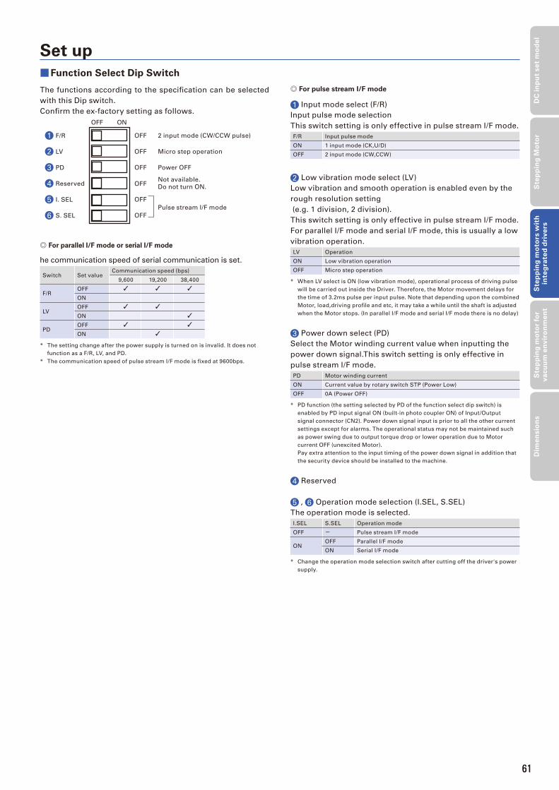
61
The functions according to the specifi cation can be selected
with this Dip switch.
Confi rm the ex-factory setting as follows.
F/R
LV
PD
Reserved
I. SEL
S. SEL
OFF 2 input mode (CW/CCW pulse)
OFF Micro step operation
OFF Power OFF
OFF Not available.
Do not turn ON.
OFF
OFF
Pulse stream I/F mode
OFF ON
1
2
3
4
5
6
Set up
■Function Select Dip Switch
◎ For pulse stream I/F mode
1 Input mode select (F/R)
Input pulse mode selection
This switch setting is only effective in pulse stream I/F mode.
F/R Input pulse mode
ON 1 input mode (CK,U/D)
OFF 2 input mode (CW,CCW)
2 Low vibration mode select (LV)
Low vibration and smooth operation is enabled even by the
rough resolution setting
(e.g. 1 division, 2 division).
This switch setting is only effective in pulse stream I/F mode.
For parallel I/F mode and serial I/F mode, this is usually a low
vibration operation.
LV Operation
ON Low vibration operation
OFF Micro step operation
* When LV select is ON (low vibration mode), operational process of driving pulse
will be carried out inside the Driver. Therefore, the Motor movement delays for
the time of 3.2ms pulse per input pulse. Note that depending upon the combined
Motor, load,driving profi le and etc, it may take a while until the shaft is adjusted
when the Motor stops. (In parallel I/F mode and serial I/F mode there is no delay)
3 Power down select (PD)
Select the Motor winding current value when inputting the
power down signal.This switch setting is only effective in
pulse stream I/F mode.
PD Motor winding current
ON Current value by rotary switch STP (Power Low)
OFF 0A (Power OFF)
* PD function (the setting selected by PD of the function select dip switch) is
enabled by PD input signal ON (built-in photo coupler ON) of Input/Output
signal connector (CN2). Power down signal input is prior to all the other current
settings except for alarms. The operational status may not be maintained such
as power swing due to output torque drop or lower operation due to Motor
current OFF (unexcited Motor).
Pay extra attention to the input timing of the power down signal in addition that
the security device should be installed to the machine.
4 Reserved
5 , 6 Operation mode selection (I.SEL, S.SEL)
The operation mode is selected.
I.SEL S.SEL Operation mode
OFF - Pulse stream I/F mode
ONOFF Parallel I/F mode
ON Serial I/F mode
* Change the operation mode selection switch after cutting off the driver's power
supply.
◎ For parallel I/F mode or serial I/F mode
he communication speed of serial communication is set.
Switch Set valueCommunication speed (bps)
9,600 19,200 38,400
F/ROFF
ON
LVOFF
ON
PDOFF
ON
* The setting change after the power supply is turned on is invalid. It does not
function as a F/R, LV, and PD.
* The communication speed of pulse stream I/F mode is fi xed at 9600bps.
61
DC
in
pu
t se
t m
od
el
Ste
pp
ing
Mo
tor
Ste
pp
ing
mo
tors
wit
h
inte
gra
ted
dri
ve
rsS
tep
pin
g m
oto
r fo
r v
acu
um
en
vir
on
me
nt
Dim
en
sio
ns
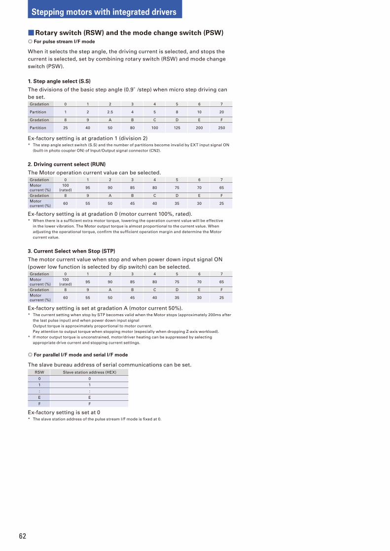
62
Stepping motors with integrated drivers
■Rotary switch (RSW) and the mode change switch (PSW)
◎ For pulse stream I/F mode
When it selects the step angle, the driving current is selected, and stops the
current is selected, set by combining rotary switch (RSW) and mode change
switch (PSW).
1. Step angle select (S.S)
The divisions of the basic step angle (0.9°/step) when micro step driving can
be set.
Gradation 0 1 2 3 4 5 6 7
Partition 1 2 2.5 4 5 8 10 20
Gradation 8 9 A B C D E F
Partition 25 40 50 80 100 125 200 250
Ex-factory setting is at gradation 1 (division 2)
* The step angle select switch (S.S) and the number of partitions become invalid by EXT input signal ON
(built-in photo coupler ON) of Input/Output signal connector (CN2).
2. Driving current select (RUN)
The Motor operation current value can be selected.
Gradation 0 1 2 3 4 5 6 7
Motor
current (%)
100
(rated)95 90 85 80 75 70 65
Gradation 8 9 A B C D E F
Motor
current (%)60 55 50 45 40 35 30 25
Ex-factory setting is at gradation 0 (motor current 100%, rated).
* When there is a suffi cient extra motor torque, lowering the operation current value will be effective
in the lower vibration. The Motor output torque is almost proportional to the current value. When
adjusting the operational torque, confi rm the suffi cient operation margin and determine the Motor
current value.
3. Current Select when Stop (STP)
The motor current value when stop and when power down input signal ON
(power low function is selected by dip switch) can be selected.
Gradation 0 1 2 3 4 5 6 7
Motor
current (%)
100
(rated)95 90 85 80 75 70 65
Gradation 8 9 A B C D E F
Motor
current (%)60 55 50 45 40 35 30 25
Ex-factory setting is set at gradation A (motor current 50%).
* The current setting when stop by STP becomes valid when the Motor stops (approximately 200ms after
the last pulse input) and when power down input signal
Output torque is approximately proportional to motor current.
Pay attention to output torque when stopping motor (especially when dropping Z-axis workload).
* If motor output torque is unconstrained, motor/driver heating can be suppressed by selecting
appropriate drive current and stopping current settings.
◎ For parallel I/F mode and serial I/F mode
The slave bureau address of serial communications can be set.
RSW Slave station address (HEX)
0 0
1 1
: :
E E
F F
Ex-factory setting is set at 0
* The slave station address of the pulse stream I/F mode is fi xed at 0.
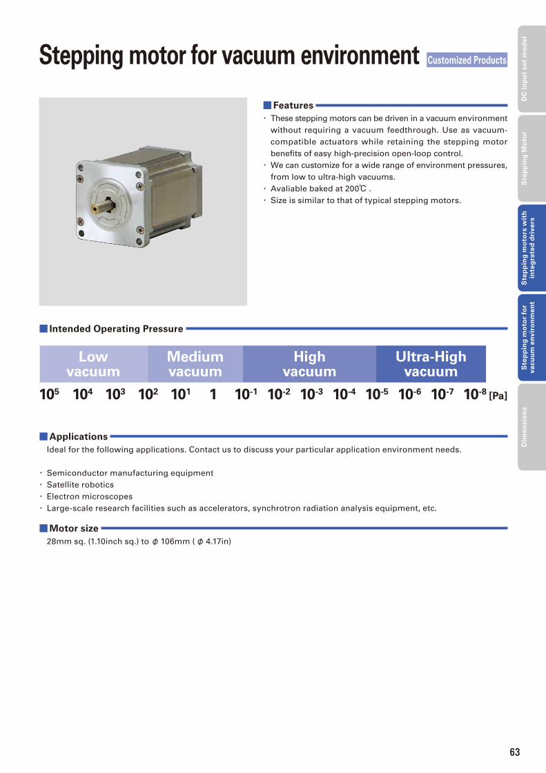
63
Stepping motor for vacuum environment Customized Products
■Features
・ These stepping motors can be driven in a vacuum environment
without requiring a vacuum feedthrough. Use as vacuum-
compatible actuators while retaining the stepping motor
benefi ts of easy high-precision open-loop control.
・ We can customize for a wide range of environment pressures,
from low to ultra-high vacuums.
・ Avaliable baked at 200℃ .
・ Size is similar to that of typical stepping motors.
■Applications
Ideal for the following applications. Contact us to discuss your particular application environment needs.
・ Semiconductor manufacturing equipment
・ Satellite robotics
・ Electron microscopes
・ Large-scale research facilities such as accelerators, synchrotron radiation analysis equipment, etc.
■Motor size
28mm sq. (1.10inch sq.) to φ 106mm (φ 4.17in)
■ Intended Operating Pressure
10-710-6 10-8[Pa]10-510-410-310-210-11101102103104105
Ultra-Highvacuum
Highvacuum
Mediumvacuum
Lowvacuum
63
DC
in
pu
t se
t m
od
el
Ste
pp
ing
Mo
tor
Ste
pp
ing
mo
tors
wit
h
inte
gra
ted
dri
ve
rsS
tep
pin
g m
oto
r fo
r v
acu
um
en
vir
on
me
nt
Dim
en
sio
ns
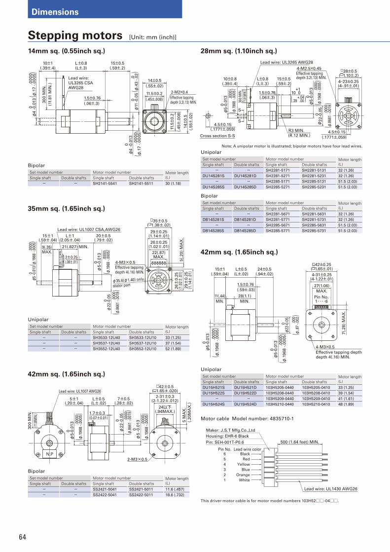
64
Dimensions
Stepping motors [Unit: mm (inch)]
14mm sq. (0.55inch sq.) 28mm sq. (1.10inch sq.)
4.5±0.15(.1771±.059)
(.1771±.059)
28±0.5( 1.10±.2)
0.0
13
φ5-0
.013
10±0.8(.39±.4)
300
MIN
.
(11.
81M
IN.)
S
S
L±0.8(L±.3)
15±0.5(.59±.2)
+110 0
0.0
13
φ5-0
.013
0.1
3φ
22-0
.05
4.5±0.15
4-23±0.25(4-.91±.01)
1.5±0.76(.06±.3)
R3 MIN.
(R.12 MIN.)
4-M2.5×0.45
Effective tapping depth 3.2(.13) MIN.
Lead wire: UL3265 AWG28
Cross section S-S
.000
0-.
0005
()
φ.1
968
.000
0-.
0019
()
φ.8
661
+.04.00( ).39
.000
0-.
0005
()
φ.1
968
Effective tapping depth depth 4(.16) MIN.
4-M3×0.5
L±0.5(L±.02)
24±0.5(.94±.02)
42±0.25( 1.65±.01)
4-31±0.25(4-1.22±.01)
27(1.06)
MAX.
7(.
28)
MA
X.
Pin No.1・・・・6
15±1(.59±.04)
0.0
13
φ5-0
.013
0.0
13
φ5-0
.013
0.0
5φ
22-0
.05
28(1.1)
MIN.
11(.44)
MIN.
1.5±0.76
(.59±.03)
.0000
-.0005
()
φ.1
96
8
.0000
-.0005
()
φ.1
96
8
.000
-.00
2(
)φ
..87
35mm sq. (1.65inch sq.)
Lead wire: UL1007 CSA,AWG26
21(.827) MIN.
15±1(.59±.04)
L±1(2.05±.04)
20±0.5(.79±.02)
9(.35)MAX.
300(
11.8
1)M
IN.
2±0.25(.08±.01)
φ5-0
.013
0
φ22-0
.05
0
4-M3×0.5
φ35.6(φ1.40) only
stator part
35±0.5( 1.38±.02)
29±0.25(1.14±.01)
26±0.25(1.02±.01)
22(.87)MAX.
26±
0.2
5(1
.02±
.01)
5(.
20)
MA
X.
29±
0.2
5(1
.14±
.01)
Effective tapping depth 4(.16) MIN.
φ5
0 -0.0
13 .0
000
-.00
05(
)φ
.196
8
.000
0-.
0005
()
φ.1
968
.000
0-.
0019
()
φ.8
661
N.P
7±0.5(.28±.02)
φ22
0 -0.0
5
φ5
0 -0.0
13
2-31±0.3(2-1.22±.012)
24以下(.94MAX.)
42±0.5( 1.65±.020)
5 M
AX
.
(.20M
AX
.)
2-M3×0.5
30
0 M
IN.
(11.
8MIN
.)
Lead wire: UL1007 AWG26
5±1(.20±.04)
L±0.5(L±.02)
φ5 0 -0
.013
1.7±0.3(0.07±0.01)
.0000
-.0005
()
φ.1
968
.0000
-.0005
()
φ.1
968
.000
0-.
0019
()
φ.8
661
42mm sq. (1.65inch sq.)
42mm sq. (1.65inch sq.)
Unipolar
Set model number Motor model number Motor length (L)Single shaft Double shafts Single shaft Double shafts
- - SH2281-5171 SH2281-5131 32 (1.26)
DU14S281S DU14S281D SH2281-5271 SH2281-5231 32 (1.26)
- - SH2285-5171 SH2285-5131 51.5 (2.03)
DU14S285S DU14S285D SH2285-5271 SH2285-5231 51.5 (2.03)
Bipolar
Set model number Motor model number Motor length (L)Single shaft Double shafts Single shaft Double shafts
- - SH2281-5671 SH2281-5631 32 (1.26)
DB14S281S DB14S281D SH2281-5771 SH2281-5731 32 (1.26)
- - SH2285-5671 SH2285-5631 51.5 (2.03)
DB14S285S DB14S285D SH2285-5771 SH2285-5731 51.5 (2.03)
Unipolar
Set model number Motor model number Motor length (L)Single shaft Double shafts Single shaft Double shafts
DU15H521S DU15H521D 103H5205-0440 103H5205-0410 33 (1.25)
DU15H522S DU15H522D 103H5208-0440 103H5208-0410 39 (1.54)
- - 103H5209-0440 103H5209-0410 41 (1.61)
DU15H524S DU15H524D 103H5210-0440 103H5210-0410 48 (1.89)
Unipolar
Set model number Motor model number Motor length (L)Single shaft Double shafts Single shaft Double shafts
- - SH3533-12U40 SH3533-12U10 33 (1.25)
- - SH3537-12U40 SH3537-12U10 37 (1.54)
- - SH3552-12U40 SH3552-12U10 52 (1.89)
Bipolar
Set model number Motor model number Motor length (L)Single shaft Double shafts Single shaft Double shafts
- - SS2421-5041 SS2421-5011 11.6 (.457)
- - SS2422-5041 SS2422-5011 18.6 (.732)
500 (1.64 feet) MIN.
Pin No.Black
Red
Yellow
Blue
Orange
White
6
5
4
3
2
1
Lead wire color
Maker: J.S.T Mfg.Co.,Ltd
Lead wire: UL1430 AWG26
Housing: EHR-6 Black
Pin: SEH-001T-P0.6
Motor cable Model number: 4835710-1
Lead wire:UL3265 CSA AWG28
30
0 M
IN.
(11.
81
MIN
.)
φ4
0 -0.0
13
.0
00
0-.
00
05
10±1(.39±.4)
L±0.8(L±.3)
1.5±0.76
(.06±.3)
15±0.5(.59±.2)
φ4
0 -0.0
13
φ11
0 -0.0
5 2-M2×0.4
Effective tapping depth 3.2(.13) MIN.
11.5±0.2
(.45±.008)
14±0.5
(.55±.02)
11.5±
0.2
(.4
5±
.00
8)
14±
0.5
(.5
5±
.02
)
()
φ.1
7
.0
-.0
2(
)φ
.43
.0
00
0-.
00
05
()
φ.1
7
This driver-motor cable is for motor model numbers 103H52□□-04□□.
Bipolar
Set model number Motor model number Motor length (L)Single shaft Double shafts Single shaft Double shafts
- - SH2141-5541 SH2141-5511 30 (1.18)
Note: A unipolar motor is illustrated; bipolar motors have four lead wires.
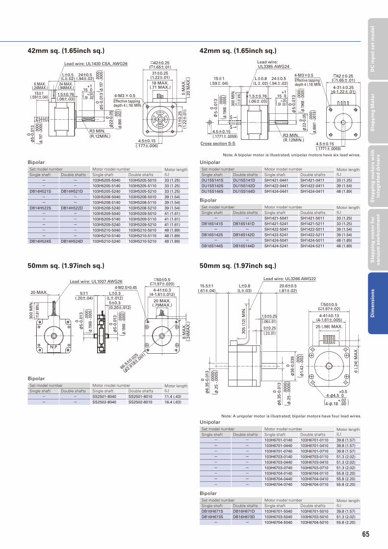
65
DC
in
pu
t se
t m
od
el
Ste
pp
ing
Mo
tor
Ste
pp
ing
mo
tors
wit
h
inte
gra
ted
dri
ve
rsS
tep
pin
g m
oto
r fo
r v
acu
um
en
vir
on
me
nt
Dim
en
sio
ns
4-M3×0.5
Effective tapping depth 4 (.16) MIN.
φ5-0
.013
0
Cross section S-S
4.5±0.15(.1771±.0059)
4-31±0.25(4-1.22±.01)
Lead wire: UL3385 AWG24
300 M
IN.
(11.8
1 MIN
.)
R3 MIN.(R.12MIN.)
S
S
24±0.5(.94±.02)
L±0.8(L±.02)
15±1(.59±.04)
4.5±0.15(.1771±.0059)
1.5±0.76
(.06±.03)
φ22-0
.05
0
15 0+1
φ5
-0.0
13
0
42±0.25( 1.65±.01)
.000
0-.
0005
()
φ.1
968
.000
0-.
0005
()
φ.1
968
.000
0-.
0019
()
φ.8
661
+.04.00( ).59
42mm sq. (1.65inch sq.)
50mm sq. (1.97inch sq.)
22
φ
φ5-0
.013
0 -0.0
5
04-M3 × 0.5
Effective tapping depth 4 (.16) MIN.
+1
R3 MIN.
(R.12MIN.)
φ5-0
.013
0
15 0
24±0.5(.94±.02)
15±1(.591±.04)
1.5±0.76(.06±.03)
L±0.5(L±.02)
6 MAX.(.24MAX.)
24 MAX.(.94MAX.)
31±0.25(1.22±.01)
18 MAX.(.71 MAX.)
5 M
AX
.
(.20 M
AX
.)
4.5±0.15
(.177±.006)
31±
0.2
5
(1.2
2±
.01)
Lead wire: UL1430 CSA, AWG26 42±0.25( 1.65±.01)
.000
0-.
0005
()
φ.1
97
.000
0-.
0005
()
φ.1
97
.000
-.00
2(
)φ
.866
+.04.00( ).59
42mm sq. (1.65inch sq.)
50mm sq. (1.97inch sq.)
Unipolar
Set model number Motor model number Motor length (L)Single shaft Double shafts Single shaft Double shafts
DU15S141S DU15S141D SH1421-0441 SH1421-0411 33 (1.25)
DU15S142S DU15S142D SH1422-0441 SH1422-0411 39 (1.54)
DU15S144S DU15S144D SH1424-0441 SH1424-0411 48 (1.89)
Bipolar
Set model number Motor model number Motor length (L)Single shaft Double shafts Single shaft Double shafts
- - SH1421-5041 SH1421-5011 33 (1.25)
DB16S141S DB16S141D SH1421-5241 SH1421-5211 33 (1.25)
- - SH1422-5041 SH1422-5011 39 (1.54)
DB16S142S DB16S142D SH1422-5241 SH1422-5211 39 (1.54)
- - SH1424-5041 SH1424-5011 48 (1.89)
DB16S144S DB16S144D SH1424-5241 SH1424-5211 48 (1.89)
Unipolar
Set model number Motor model number Motor length (L)Single shaft Double shafts Single shaft Double shafts
- - 103H6701-0140 103H6701-0110 39.8 (1.57)
- - 103H6701-0440 103H6701-0410 39.8 (1.57)
- - 103H6701-0740 103H6701-0710 39.8 (1.57)
- - 103H6703-0140 103H6703-0110 51.3 (2.02)
- - 103H6703-0440 103H6703-0410 51.3 (2.02)
- - 103H6703-0740 103H6703-0710 51.3 (2.02)
- - 103H6704-0140 103H6704-0110 55.8 (2.20)
- - 103H6704-0440 103H6704-0410 55.8 (2.20)
- - 103H6704-0740 103H6704-0710 55.8 (2.20)
Bipolar
Set model number Motor model number Motor length (L)Single shaft Double shafts Single shaft Double shafts
DB16H671S DB16H671D 103H6701-5040 103H6701-5010 39.8 (1.57)
DB16H673S DB16H673D 103H6703-5040 103H6703-5010 51.3 (2.02)
- - 103H6704-5040 103H6704-5010 55.8 (2.20)
Bipolar
Set model number Motor model number Motor length (L)Single shaft Double shafts Single shaft Double shafts
- - 103H5205-5040 103H5205-5010 33 (1.25)
- - 103H5205-5140 103H5205-5110 33 (1.25)
DB14H521S DB14H521D 103H5205-5240 103H5205-5210 33 (1.25)
- - 103H5208-5040 103H5208-5010 39 (1.54)
- - 103H5208-5140 103H5208-5110 39 (1.54)
DB14H522S DB14H522D 103H5208-5240 103H5208-5210 39 (1.54)
- - 103H5209-5040 103H5209-5010 41 (1.61)
- - 103H5209-5140 103H5209-5110 41 (1.61)
- - 103H5209-5240 103H5209-5210 41 (1.61)
- - 103H5210-5040 103H5210-5010 48 (1.89)
- - 103H5210-5140 103H5210-5110 48 (1.89)
DB14H524S DB14H524D 103H5210-5240 103H5210-5210 48 (1.89)
Bipolar
Set model number Motor model number Motor length (L)Single shaft Double shafts Single shaft Double shafts
- - SS2501-8040 SS2501-8010 11.4 (.43)
- - SS2502-8040 SS2502-8010 16.4 (.63)
Lead wire: UL3266 AWG22
15.5±1(.61±.04)
L±0.8(L±.03)
20.6±0.5(.81±.02)
50±0.5( 1.97±.02)
4-41±0.13(4-1.61±.005)
+0.54-φ4.5 0.5
6 (
.24)
MA
X.
25 (.98) MAX.
305 (
12)
MIN
.
1.5±0.25
(.06±.01)
5±0.25
(.2±.01)
0.0
00
φ6.3
5-0
.013
0.0
00
φ36-0
.039
00
00
φ6.3
5-0
.013 .
0000
-.0005
()
φ.2
5
.0000
-.0005
()
φ.2
5
.000
-.002
()
φ1.
42
+.02.00( )4-φ.18
N.P
30
0 M
IN.
(11.
81 M
IN.)
20 MAX.
20 MAX.(.79MAX.)
6 M
AX
.(.
24M
AX
.)
Lead wire: UL1007 AWG26
5±1(.20±.04)
L±0.3(L±.012)5±0.3 (0.20±.012)
φ5-0
.013
0
φ5-0
.013
0
4-M2.5×0.454-41±0.3
(4-1.61±.012)
50±0.5( 1.97±.020)
66.5±0.0
25
(φ2.6
18±.0
01)
.000
0-.
0005
()
φ.1
968 .0
000
-.00
05(
)φ
.196
8
Note: A bipolar motor is illustrated; unipolar motors have six lead wires.
Note: A unipolar motor is illustrated; bipolar motors have four lead wires.
65
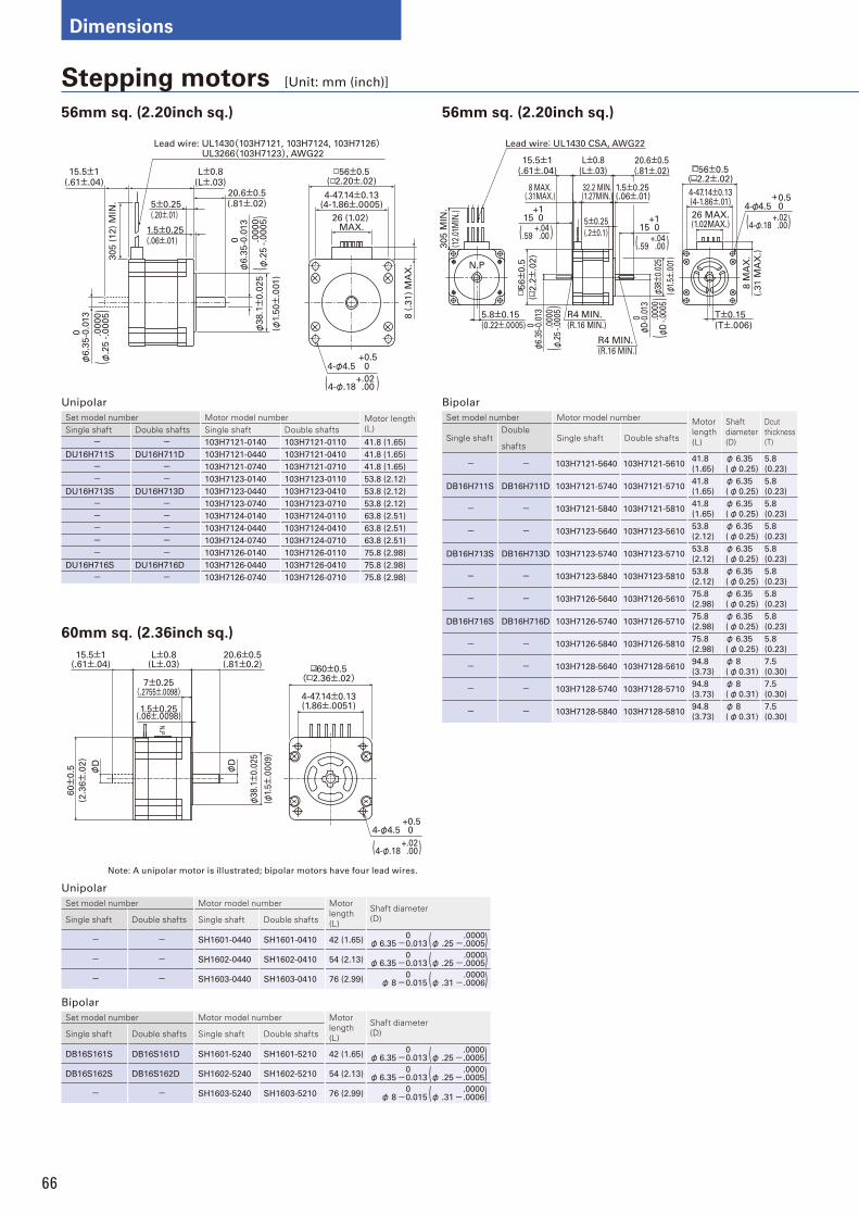
66
Dimensions
+0.54-φ4.5 0.0
8 (
.31)
MA
X.
26 (1.02) MAX.
Lead wire: UL1430(103H7121, 103H7124, 103H7126)UL3266(103H7123), AWG22
305 (
12)
MIN
.
15.5±1(.61±.04)
L±0.8(L±.03)
20.6±0.5(.81±.02)
56±0.5( 2.20±.02)
4-47.14±0.13(4-1.86±.0005)5±0.25
(.20±.01)
00
00
φ6.3
5-0
.013
00
00
φ6.3
5-0
.013
φ38.1±
0.0
25
(φ1.
50±
.001)
1.5±0.25(.06±.01)
.0000
-.0005
()
φ.2
5
+.02.00( )4-φ.18
.0000
-.0005
()
φ.2
5
Stepping motors [Unit: mm (inch)]
Unipolar
Set model number Motor model number Motor length (L)Single shaft Double shafts Single shaft Double shafts
- - 103H7121-0140 103H7121-0110 41.8 (1.65)
DU16H711S DU16H711D 103H7121-0440 103H7121-0410 41.8 (1.65)
- - 103H7121-0740 103H7121-0710 41.8 (1.65)
- - 103H7123-0140 103H7123-0110 53.8 (2.12)
DU16H713S DU16H713D 103H7123-0440 103H7123-0410 53.8 (2.12)
- - 103H7123-0740 103H7123-0710 53.8 (2.12)
- - 103H7124-0140 103H7124-0110 63.8 (2.51)
- - 103H7124-0440 103H7124-0410 63.8 (2.51)
- - 103H7124-0740 103H7124-0710 63.8 (2.51)
- - 103H7126-0140 103H7126-0110 75.8 (2.98)
DU16H716S DU16H716D 103H7126-0440 103H7126-0410 75.8 (2.98)
- - 103H7126-0740 103H7126-0710 75.8 (2.98)
Bipolar
Set model number Motor model number Motor length (L)
Shaft diameter(D)
Dcutthickness(T)Single shaft
Double
shaftsSingle shaft Double shafts
- - 103H7121-5640 103H7121-561041.8
(1.65)
φ 6.35
(φ0.25)
5.8
(0.23)
DB16H711S DB16H711D 103H7121-5740 103H7121-571041.8
(1.65)
φ 6.35
(φ0.25)
5.8
(0.23)
- - 103H7121-5840 103H7121-581041.8
(1.65)
φ 6.35
(φ0.25)
5.8
(0.23)
- - 103H7123-5640 103H7123-561053.8
(2.12)
φ 6.35
(φ0.25)
5.8
(0.23)
DB16H713S DB16H713D 103H7123-5740 103H7123-571053.8
(2.12)
φ 6.35
(φ0.25)
5.8
(0.23)
- - 103H7123-5840 103H7123-581053.8
(2.12)
φ 6.35
(φ0.25)
5.8
(0.23)
- - 103H7126-5640 103H7126-561075.8
(2.98)
φ 6.35
(φ0.25)
5.8
(0.23)
DB16H716S DB16H716D 103H7126-5740 103H7126-571075.8
(2.98)
φ 6.35
(φ0.25)
5.8
(0.23)
- - 103H7126-5840 103H7126-581075.8
(2.98)
φ 6.35
(φ0.25)
5.8
(0.23)
- - 103H7128-5640 103H7128-561094.8
(3.73)
φ 8
(φ0.31)
7.5
(0.30)
- - 103H7128-5740 103H7128-571094.8
(3.73)
φ 8
(φ0.31)
7.5
(0.30)
- - 103H7128-5840 103H7128-581094.8
(3.73)
φ 8
(φ0.31)
7.5
(0.30)
56mm sq. (2.20inch sq.)
60mm sq. (2.36inch sq.)
56mm sq. (2.20inch sq.)
+0.54-φ4.5 0
N.P
φD
φD
15.5±1(.61±.04)
L±0.8(L±.03)
20.6±0.5(.81±0.2)
7±0.25(.2755±.0098)
1.5±0.25(.06±.0098)
60±
0.5
(2.3
6±
.02)
φ38.1±
0.0
25
( φ1.
5±.0
009)
60±0.5( 2.36±.02)
4-47.14±0.13(1.86±.0051)
+.02.00( )4-φ.18
15.5±1(.61±.04)
8 MAX.(.31MAX.)
L±0.8(L±.03)
32.2 MIN.(1.27MIN.)
5±0.25
(.2±0.1)
20.6±0.5(.81±.02)
1.5±0.25(.06±.01)
56±0.5( 2.2±.02)
4-47.14±0.13(4-1.86±.01)
26 MAX.(1.02MAX.)
8 M
AX
.
(.31 M
AX
.)
305 M
IN.
(12.
01M
IN.)
5.8±0.15(0.22±.0005)
R4 MIN.(R.16 MIN.)
R4 MIN.(R.16 MIN.)
15 0+1
15 0+1
Lead wire: UL1430 CSA, AWG22
T±0.15(T±.006)
4-φ4.5+0.5
0
φ38±
0.02
5
(φ1.
5±.0
01)
φD-0
.013
0
φ6.3
5-0.
013
056±
0.5
(2.2±
.02)
N.P
.000
0-.
0005
()
φD .0
000
-.00
05(
)φ
.25
+.02.00( )4-φ.18+.04
.00( ).59 +.04.00( ).59
Unipolar
Set model number Motor model number Motor length (L)
Shaft diameter(D)Single shaft Double shafts Single shaft Double shafts
- - SH1601-0440 SH1601-0410 42 (1.65) φ6.350
-0.013 (φ .25.0000-.0005)
- - SH1602-0440 SH1602-0410 54 (2.13) φ6.350
-0.013 (φ .25.0000-.0005)
- - SH1603-0440 SH1603-0410 76 (2.99) φ 80
-0.015 (φ .31.0000-.0006)
Bipolar
Set model number Motor model number Motor length (L)
Shaft diameter(D)Single shaft Double shafts Single shaft Double shafts
DB16S161S DB16S161D SH1601-5240 SH1601-5210 42 (1.65) φ6.350
-0.013 (φ .25.0000-.0005)
DB16S162S DB16S162D SH1602-5240 SH1602-5210 54 (2.13) φ6.350
-0.013 (φ .25.0000-.0005)
- - SH1603-5240 SH1603-5210 76 (2.99) φ 80
-0.015 (φ .31.0000-.0006)
Note: A unipolar motor is illustrated; bipolar motors have four lead wires.
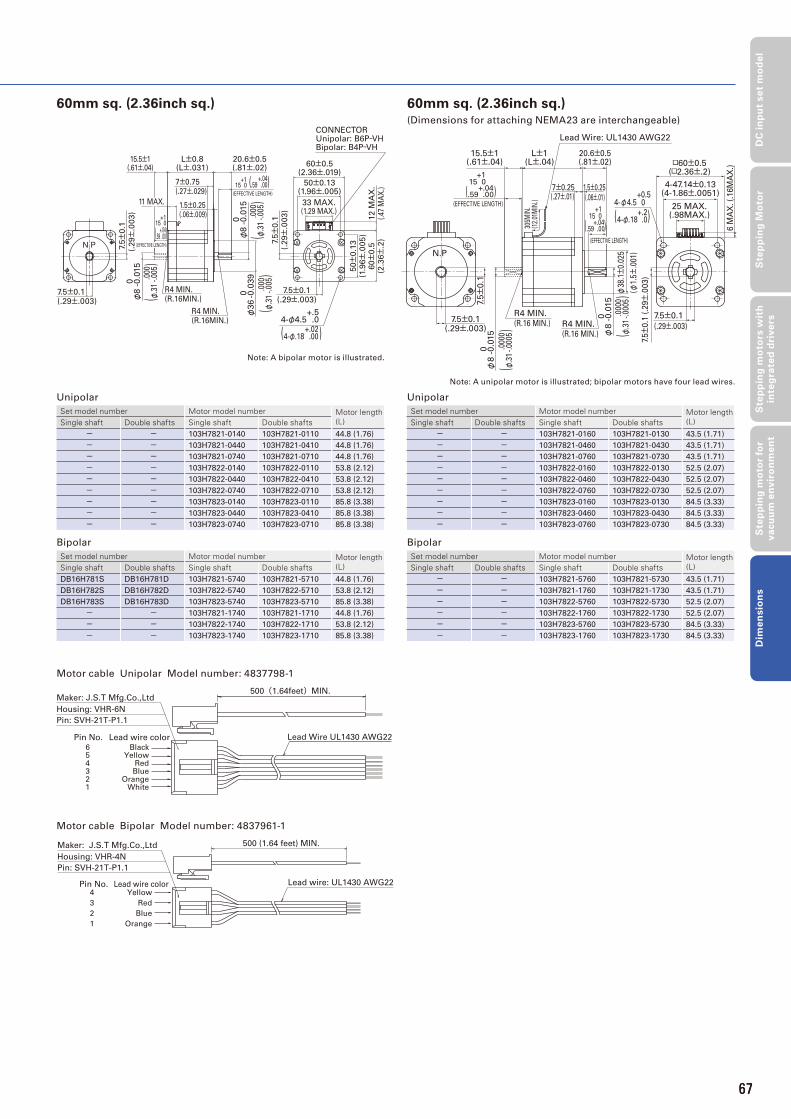
67
DC
in
pu
t se
t m
od
el
Ste
pp
ing
Mo
tor
Ste
pp
ing
mo
tors
wit
h
inte
gra
ted
dri
ve
rsS
tep
pin
g m
oto
r fo
r v
acu
um
en
vir
on
me
nt
Dim
en
sio
ns
60mm sq. (2.36inch sq.)
L±0.8(L±.031)
20.6±0.5(.81±.02)
60±0.5(2.36±.019)
50±0.13(1.96±.005)
7±0.75(.27±.029)
1.5±0.25(.06±.009)
15.5±1(.61±.04)
11 MAX. 33 MAX.(1.29 MAX.)
12 M
AX
.(.
47 M
AX
.)
7.5±
0.1
(.29±
.003)
50±
0.1
3(1
.96±
.005)
60±
0.5
(2.3
6±
.2)
7.5±0.1(.29±.003)
R4 MIN.(R.16MIN.)
R4 MIN.(R.16MIN.)
7.5±
0.1
(.29±
.003)
7.5±0.1(.29±.003)
CONNECTORUnipolar: B6P-VHBipolar: B4P-VH
15 0+1
(EFFECTIVE LENGTH)
15 0+1
(EFFECTIVE LENGTH)
φ8
0 -0.0
15
.000
-.00
5(
)φ
.31
.000
-.00
5(
)φ
.31
+.02.00( )4-φ.18
φ8
0 -0.0
15
φ36
0 -0.0
39
4-φ4.5+.5
.0
.000
-.00
5(
)φ
.31
+.04.00( ).59
+.04.00( ).59
Motor cable Unipolar Model number: 4837798-1
500(1.64feet)MIN.
654321
Pin No.
BlackYellow
RedBlue
OrangeWhite
Lead wire color Lead Wire UL1430 AWG22
Maker: J.S.T Mfg.Co.,Ltd
Housing: VHR-6N
Pin: SVH-21T-P1.1
Motor cable Bipolar Model number: 4837961-1
4
3
2
1
Pin No.Yellow
Red
Blue
Orange
Lead wire color
Maker: J.S.T Mfg.Co.,Ltd
Housing: VHR-4N
Pin: SVH-21T-P1.1
500 (1.64 feet) MIN.
Lead wire: UL1430 AWG22
Unipolar
Set model number Motor model number Motor length (L)Single shaft Double shafts Single shaft Double shafts
- - 103H7821-0140 103H7821-0110 44.8 (1.76)
- - 103H7821-0440 103H7821-0410 44.8 (1.76)
- - 103H7821-0740 103H7821-0710 44.8 (1.76)
- - 103H7822-0140 103H7822-0110 53.8 (2.12)
- - 103H7822-0440 103H7822-0410 53.8 (2.12)
- - 103H7822-0740 103H7822-0710 53.8 (2.12)
- - 103H7823-0140 103H7823-0110 85.8 (3.38)
- - 103H7823-0440 103H7823-0410 85.8 (3.38)
- - 103H7823-0740 103H7823-0710 85.8 (3.38)
Bipolar
Set model number Motor model number Motor length (L)Single shaft Double shafts Single shaft Double shafts
DB16H781S DB16H781D 103H7821-5740 103H7821-5710 44.8 (1.76)
DB16H782S DB16H782D 103H7822-5740 103H7822-5710 53.8 (2.12)
DB16H783S DB16H783D 103H7823-5740 103H7823-5710 85.8 (3.38)
- - 103H7821-1740 103H7821-1710 44.8 (1.76)
- - 103H7822-1740 103H7822-1710 53.8 (2.12)
- - 103H7823-1740 103H7823-1710 85.8 (3.38)
Unipolar
Set model number Motor model number Motor length (L)Single shaft Double shafts Single shaft Double shafts
- - 103H7821-0160 103H7821-0130 43.5 (1.71)
- - 103H7821-0460 103H7821-0430 43.5 (1.71)
- - 103H7821-0760 103H7821-0730 43.5 (1.71)
- - 103H7822-0160 103H7822-0130 52.5 (2.07)
- - 103H7822-0460 103H7822-0430 52.5 (2.07)
- - 103H7822-0760 103H7822-0730 52.5 (2.07)
- - 103H7823-0160 103H7823-0130 84.5 (3.33)
- - 103H7823-0460 103H7823-0430 84.5 (3.33)
- - 103H7823-0760 103H7823-0730 84.5 (3.33)
Bipolar
Set model number Motor model number Motor length (L)Single shaft Double shafts Single shaft Double shafts
- - 103H7821-5760 103H7821-5730 43.5 (1.71)
- - 103H7821-1760 103H7821-1730 43.5 (1.71)
- - 103H7822-5760 103H7822-5730 52.5 (2.07)
- - 103H7822-1760 103H7822-1730 52.5 (2.07)
- - 103H7823-5760 103H7823-5730 84.5 (3.33)
- - 103H7823-1760 103H7823-1730 84.5 (3.33)
60mm sq. (2.36inch sq.)(Dimensions for attaching NEMA23 are interchangeable)
4-φ4.5 0 +0.5
R4 MIN.(R.16 MIN.)
R4 MIN.(R.16 MIN.)
φ8 -
0.0
15
0
φ8 -
0.0
15
0
□60±0.5(□2.36±.2)
4-47.14±0.13(4-1.86±.0051)
7±0.25(.27±.01)
1.5±0.25(.06±.01)
305M
IN.
(12.
01M
IN.)
φ38
.1±
0.02
5
(φ1.
5±.0
01)
6 M
AX
. (.
16M
AX
.)
L±1(L±.04)
20.6±0.5(.81±.02)
15.5±1(.61±.04)
25 MAX.(.98MAX.)
7.5±0.1
(.29±.003)
7.5±
0.1
(.2
9±.0
03)
Lead Wire: UL1430 AWG22
15 0+1
(EFFECTIVE LENGTH)
15 0+1
(EFFECTIVE LENGTH)
N.P
7.5±
0.1
7.5±0.1(.29±.003)
.000
0-.
0005
()
φ.3
1
.000
0-.
0005
()
φ.3
1
+.2.0( )4-φ.18+.04
.00( ).59
+.04.00( ).59
Note: A bipolar motor is illustrated.
Note: A unipolar motor is illustrated; bipolar motors have four lead wires.
67
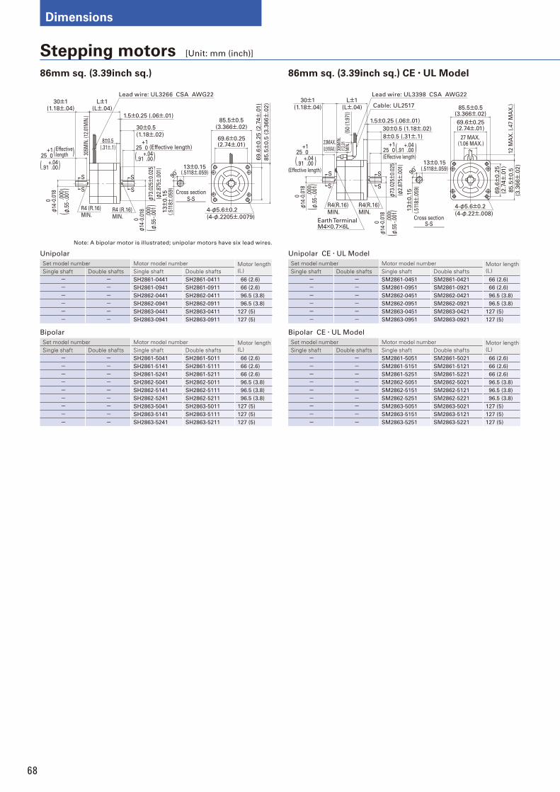
68
Dimensions
Stepping motors [Unit: mm (inch)]
Unipolar CE・UL Model
Set model number Motor model number Motor length (L)Single shaft Double shafts Single shaft Double shafts
- - SM2861-0451 SM2861-0421 66 (2.6)
- - SM2861-0951 SM2861-0921 66 (2.6)
- - SM2862-0451 SM2862-0421 96.5 (3.8)
- - SM2862-0951 SM2862-0921 96.5 (3.8)
- - SM2863-0451 SM2863-0421 127 (5)
- - SM2863-0951 SM2863-0921 127 (5)
Bipolar CE・UL Model
Set model number Motor model number Motor length (L)Single shaft Double shafts Single shaft Double shafts
- - SM2861-5051 SM2861-5021 66 (2.6)
- - SM2861-5151 SM2861-5121 66 (2.6)
- - SM2861-5251 SM2861-5221 66 (2.6)
- - SM2862-5051 SM2862-5021 96.5 (3.8)
- - SM2862-5151 SM2862-5121 96.5 (3.8)
- - SM2862-5251 SM2862-5221 96.5 (3.8)
- - SM2863-5051 SM2863-5021 127 (5)
- - SM2863-5151 SM2863-5121 127 (5)
- - SM2863-5251 SM2863-5221 127 (5)
Unipolar
Set model number Motor model number Motor length (L)Single shaft Double shafts Single shaft Double shafts
- - SH2861-0441 SH2861-0411 66 (2.6)
- - SH2861-0941 SH2861-0911 66 (2.6)
- - SH2862-0441 SH2862-0411 96.5 (3.8)
- - SH2862-0941 SH2862-0911 96.5 (3.8)
- - SH2863-0441 SH2863-0411 127 (5)
- - SH2863-0941 SH2863-0911 127 (5)
Bipolar
Set model number Motor model number Motor length (L)Single shaft Double shafts Single shaft Double shafts
- - SH2861-5041 SH2861-5011 66 (2.6)
- - SH2861-5141 SH2861-5111 66 (2.6)
- - SH2861-5241 SH2861-5211 66 (2.6)
- - SH2862-5041 SH2862-5011 96.5 (3.8)
- - SH2862-5141 SH2862-5111 96.5 (3.8)
- - SH2862-5241 SH2862-5211 96.5 (3.8)
- - SH2863-5041 SH2863-5011 127 (5)
- - SH2863-5141 SH2863-5111 127 (5)
- - SH2863-5241 SH2863-5211 127 (5)
86mm sq. (3.39inch sq.) CE・UL Model 86mm sq. (3.39inch sq.)
69.6±
0.2
5 (
2.7
4±
.01)
85.5±
0.5
(3.3
66±
.02)
69.6±0.25(2.74±.01)
85.5±0.5(3.366±.02)
4-φ5.6±0.2
(4-φ.2205±.0079)
305M
IN. (
12.0
1MIN
.)
L±1(L±.04)
φ14
0
-0.0
18
φ14
0
-0.0
18
30±1(1.18±.04)
1.5±0.25 (.06±.01)
8±0.5(.31±.1)
30±0.5
(1.18±.02)
φ73
.025±
0.02
5
(φ2.
875±
.001
)
90°
13±0.15(.5118±.059)
13±
0.1
5(.
5118±
.059
)
R4 (R.16)MIN.
R4 (R.16)MIN.
Lead wire: UL3266 CSA AWG22
Cross sectionS-S
+1 025 (Effective length)
+1 025
Effective length
S
S
S
S
.000
-.00
1(
)φ
.55
.000
-.00
1(
)φ
.55
+.04.00( ).91
+.04.00( )
( )
.91
27 MAX. (1.06 MAX.)
69.6±
0.2
5(2
.74±
.01)
85.5±
0.5
(3.3
66±
.02)
12 M
AX
. (.
47 M
AX
.)
69.6±0.25(2.74±.01)
85.5±0.5(3.366±.02)
4-φ5.6±0.2
(4-φ.22±.008)
L±1
(L±.04)
φ14
0
-0.0
18
φ14
0
-0.0
18
30±1
(1.18±.04)
1.5±0.25 (.06±.01)
8±0.5 (.31±.1)
30±0.5 (1.18±.02)
305M
IN.
(12.
01M
IN.)
φ73
.025±
0.02
5
( φ2.
875±
.001
)
13±
0.1
5
(.51
18±
.059
)
90°
13±0.15(.5118±.059)
R4(R.16)
MIN.
R4(R.16)
MIN.
Lead wire: UL3398 CSA AWG22
Cable: UL2517
Cross sectionS-S
+1 025
+1 025
(Effective length)
(Effective length)
S
S
S
S
Earth TerminalM4×0.7×6L
23MAX.(0.91MAX.)
(50
(1.9
7))
.000
-.00
1(
)φ
.55
.000
-.00
1(
)φ
.55
+.04.00( ).91
+.04.00( ).91
Note: A bipolar motor is illustrated; unipolar motors have six lead wires.
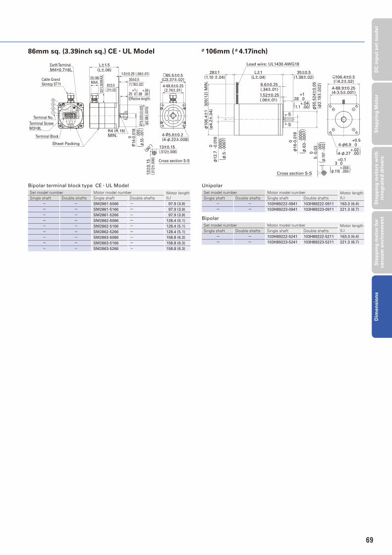
69
DC
in
pu
t se
t m
od
el
Ste
pp
ing
Mo
tor
Ste
pp
ing
mo
tors
wit
h
inte
gra
ted
dri
ve
rsS
tep
pin
g m
oto
r fo
r v
acu
um
en
vir
on
me
nt
Dim
en
sio
ns
φ106mm (φ4.17inch)
Unipolar
Set model number Motor model number Motor length (L)Single shaft Double shafts Single shaft Double shafts
- - 103H89222-0941 103H89222-0911 163.3 (6.4)
- - 103H89223-0941 103H89223-0911 221.3 (8.7)
Bipolar
Set model number Motor model number Motor length (L)Single shaft Double shafts Single shaft Double shafts
- - 103H89222-5241 103H89222-5211 163.3 (6.4)
- - 103H89223-5241 103H89223-5211 221.3 (8.7)
86mm sq. (3.39inch sq.) CE・UL Model
Bipolar terminal block type CE・UL Model
Set model number Motor model number Motor length (L)Single shaft Double shafts Single shaft Double shafts
- - SM2861-5066 - 97.9 (3.9)
- - SM2861-5166 - 97.9 (3.9)
- - SM2861-5266 - 97.9 (3.9)
- - SM2862-5066 - 128.4 (5.1)
- - SM2862-5166 - 128.4 (5.1)
- - SM2862-5266 - 128.4 (5.1)
- - SM2863-5066 - 158.8 (6.3)
- - SM2863-5166 - 158.8 (6.3)
- - SM2863-5266 - 158.8 (6.3)
32(1
.26)
MA
X.
25(.98)MAX.
R4 (R.16) MIN.
85.5±0.5( 3.37±.02)
4-69.6±0.25(2.74±.01)
4-φ5.6±0.2(4-φ.22±.008)
S
S
1.5±0.25 (.06±.01)
30±0.5(1.18±.02)8±0.5
(.31±.02)
0
φ14-0
.018
φ 73.
025±
0.02
5
( φ2.
88±.
0010
)
L±1.5
(L±.06)
Cable GrandSkintop ST11
Earth Terminal
M4×0.7×6L
Terminal Block
Terminal Screw
Terminal No.
M3×8L
Sheet Packing
1
2
3
4
(90°)
Cross section S-S
13±0.15(.512±.006)
13±
0.1
5(.
512±
.006
)
+1 025
(Effective length)
.000
-.00
1(
)φ
.55
+.04.00( ).98
69
+0.54-φ6.9 0.0
Lead wire: UL1430 AWG18
305(1
2)
MIN
.φ
106.4±
1(ø
4.2±
.04)
28±1(1.10 ±.04)
L±1(L±.04)
35±0.5(1.38±.02)
1.52±0.25(.06±.01)
+128 0
0.0
00
φ12.7
-0
.018
φ55.5
24±
0.0
5
(φ2.1
9±
.002)
4-88.9±0.25(4-3.5±.001)
106.4±0.5( 4.2±.02)
0.0
00
φ16-0
.018
S
S
Cross section S-S
5
-0.0
30
3+0.1
0
8.6±0.25(.34±.01)
+.04.00( )1.1
.0000
-.0007
()
φ.5
.0000
-.0007
()
φ.6
3
.000
-.00
2(
)φ
.197
+.004.000( )φ.118
+.02.00( )4-φ.27
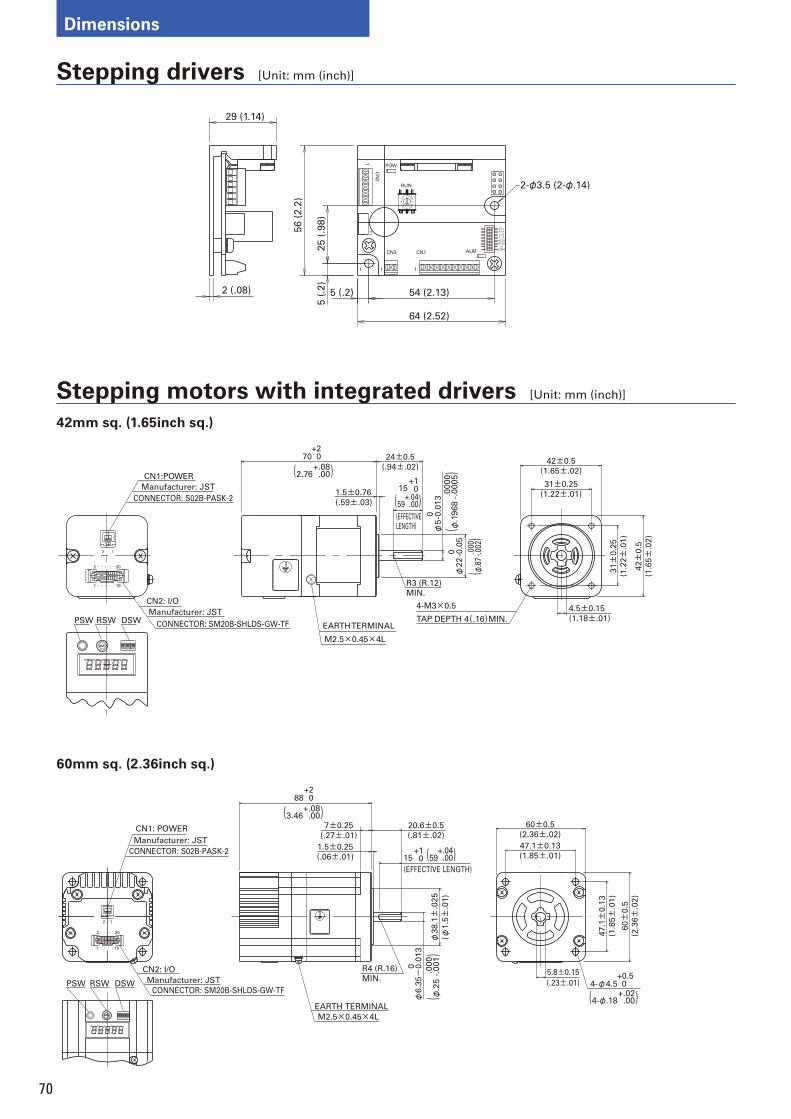
70
Dimensions
Stepping drivers [Unit: mm (inch)]
12
87
34
56
0
8
D
E
F
9A
BC
12
7
54
3
6
RUN
CN1
F1
ALM
E×1
E×2
E×3
F/R
ACD1
ACD2
LV
EORG
CN3
111
POW
CN
2
1
2-φ3.5 (2-φ.14)
ON
29 (1.14)
56
(2
.2)
25
(.9
8)
5 (
.2)
5 (.2) 54 (2.13)
64 (2.52)
2 (.08)
Stepping motors with integrated drivers [Unit: mm (inch)]
1O
42 3
N
5 6
E
9
A F
8
34
7
6 5
2
10
DCB
CN1:POWER
12
CN2: I/O
RSWPSW DSW
4.5±0.15
(1.18±.01)
42±
0.5
(1.6
5±
.02)
31±0.25
(1.22±.01)
42±0.5
(1.65±.02)
31±
0.2
5
(1.2
2±
.01)
R3 (R.12)
MIN.
φ22
0 -0.0
570
+20
15+1
01.5±0.76
(.59±.03)
24±0.5
(.94±.02)
φ5
0 -0.0
13
Manufacturer: JST
CONNECTOR: SM20B-SHLDS-GW-TF
Manufacturer: JST4-M3×0.5
M2.5×0.45×4L
EARTH TERMINAL
(EFFECTIVELENGTH)
TAP DEPTH 4(.16)MIN.
2・・・・・20
1・・・・・19
CONNECTOR: S02B-PASK-2 .0000
-.0005
()
φ.1
96
8
+.08.00( )2.76
.000
-.00
2(
)φ
.87
+.04.00( )59
6
7
A98
BC DE
01
2
5 4 3
F NO
321 654
1
4-φ4.5+0.5 0
CONNECTOR: S02B-PASK-2
Manufacturer: JST
2
Manufacturer: JST
CONNECTOR: SM20B-SHLDS-GW-TF
EARTH TERMINAL
M2.5×0.45×4L
2・・・・20
1・・・・19
88+2
0
CN1: POWER
PSW RSW DSW
CN2: I/O
7±0.25
(.27±.01)
1.5±0.25
(.06±.01)
20.6±0.5
(.81±.02)
φ38.1±
.025
(φ1.5±
.01)
φ6.3
5-
0.0
13
0
60±0.5
(2.36±.02)
47.1±0.13
(1.85±.01)
47.1±
0.1
3
(1.8
5±
.01)
60±
0.5
(2.3
6±
.02)
5.8±0.15
(.23±.01)
+.08.00( )3.46
15+1
0
(EFFECTIVE LENGTH)
+.04.00( )59
R4 (R.16)
MIN.
.000
-.001
()
φ.2
5
+.02.00( )4-φ.18
42mm sq. (1.65inch sq.)
60mm sq. (2.36inch sq.)
71
DC
in
pu
t se
t m
od
el
Ste
pp
ing
Mo
tor
Ste
pp
ing
mo
tors
wit
h
inte
gra
ted
dri
ve
rsS
tep
pin
g m
oto
r fo
r v
acu
um
en
vir
on
me
nt
Dim
en
sio
ns
Safety ConsiderationThe drivers and stepping motors are the products designed to be used for the general industrial devices.
When using those, pay enough attention to the following points.
・ Read thoroughly the Operation Manual prior to placement, assembly and/or operation in order to use the product properly.
・ Refrain from modifying or processing the product in any way.
・ Consult with the distributor or professional experts for placement or maintenance services of the product.
・ In case of the following uses of the product, contact with us for the special care required to the operation, maintenance and
management such as multiplexing the system, installing an emergency electric generator set, or so forth.
❶ Use for the medical devices concerned with a fatal accident .
❷ Use for trains, elevators, and so forth that are likely to cause an accident resulting in injury, damage or death.
❸ Use in the computer system highly infl uential to the social life or the public systems.
❹ Use in other devices highly infl uential to maintaining the human safety or the public functions.
In addition to the above, consult with us for use in such a vibration environment as automobile or transportation.
Make yourself knowledgeable and familiarize with the devices, safety issues and cautions before handling the product.
Indication by(Warning Label)on the productEither or all of the following indications are given by the Warning Labels depending on the type of the driver or stepping motor.
This label is stuck near the high voltage part such as the electrically charged or cover-protected
section, warning that the place where it is likely to cause an electric shock.
This label is stuck on the place where the driver or stepping motor body should be easily
acknowledged, warning that it is likely to cause burns from high temperature.
This label is stuck near the GND terminals of the driver or stepping motor for which grounding is
required, suggesting that the terminals should be actually grounded.
This label is stuck for the driver or stepping motor to which the power source is applied in the voltage
exceeding the safety standard, drawing attention against the electric shock.
Safety ranks of the cautionsFollowing four ranks are provided.
Improper operations or use is most likely to result in serious injury or death.
Improper operations or use is likely to result in average or minor injury, or in property damage.
In spite of the cautions with the CAUTION label, it may cause serious results.
Either the contents of the labels is describing important cautions to be followed inevitably.
Indicates what shall not be done.
Indicates what shall be done.
71
72
<General matters>1. Do not use the product in an explosive, fl ammable or corrosive
atmosphere, watery place or near a combustible material. Doing so may cause injury or fi re.
2. Have a person with expert knowledge for performing the transportation, placement, wiring, operation, maintenance or inspection of the product.
Without such knowledge, it may cause an electric shock, injury or fi re.3. Do not work for wiring, maintenance servicing or inspection with
the electric power on. Perform either of those fi ve minutes after turning the power off, or otherwise, it may cause an electric shock.
4. When the protective functions of the product is activated, turn the power off mmediately and eliminate the cause. If continuing the operation without eliminating the cause, the product may operate improperly and cause injury or a breakdown of the system devices.
5. Stepping motor may run out of order at the operating and stopping occasions, depending on the magnitude of the load. Put the product into use after confi rming with the adequate trial test operation in the maximum load conditions that the product performs reliable operation. Doing otherwise may cause a breakdown of the system. (Should the product run out of order in the use to drive upward/downward, it may cause a fall of the load.)
6. Do not touch the internal parts of the driver. Doing so may cause an electric shock.
<Wiring>7. Do not connect the stepping motor directly with the commercial power
outlet. Doing so may cause an electric shock, injury or fi re. The power shall be supplied to the stepping motor through the driving circuit.
8. Use the electric power source within the rated input voltage. Using otherwise may cause fi re or an electric shock.
9. Connect the driver and stepping motor to the ground. Using without grounding may cause an electric shock.
10. Do not harm, forcibly put a stress, or load a heavy article on the cable or get it caught between the articles. Doing so may cause an electric shock.
11. Perform wiring with the power cable as instructed by the wiring diagram or the Operation Manual. Doing otherwise may cause an electric shock or fi re.
<Operation>12. Be sure not to touch the rotating part of the stepping motor during
its operation. Touching it may cause injury.13. Neither reach or touch the electric terminals while electric power is on. Doing so may cause an electric shock.14. Never disconnect any of the connectors while electric power is on.
Doing so may cause an electric shock and corruption.
<General matters>1. Prior to placement, operation, maintenance servicing or inspection, be sure
to read the Operation Manual and follow the instructions to perform those. Failure to follow the instructions may cause an electric shock, injury or fi re.2. Do not use the driver or the stepping motor outside the specifi ed
conditions. Doing so may cause an electric shock, injury or fi re.3. Do not insert a fi nger or a thing into the opening of the product.
Doing so may cause an electric shock, injury or fi re.4. Do not use the damaged driver or stepping motor. Doing so may
cause injury, fi re or the like.5. Use the driver and stepping motor in the designated combination.
Using otherwise may cause fi re or a trouble.6. Be careful that the temperature rises in the operating driver,
stepping motor or peripheral devices. Failure to be careful may cause a burn.
<Unpacking>7. Unpack while confi rming the ceiling. Failure to do so may cause injury.8. Confi rm if the product is the one having been ordered. Installing
an incorrect product may cause a breakdown.
<Wiring>9. Do not perform measurement of the insulation resistance or
withstand insulation voltage of the product. Doing so may cause a breakdown. Instead, contact with us for such inspection.
10. Perform wiring conforming to the technical standards of electric facility or the internal rule. Doing otherwise may cause burning or fi re.
11. Ensure that wiring has been correctly done. Operating without correct wiring may cause the stepping motor to run out of control and result in injury.
12. Take insulation process for the attached condenser or the external resistance connection terminals. Failure to do so may cause an electric shock.
<Placement>13. Do not climb or attach a heavy article on the product. Doing so may
cause injury.14. Neither block nor stuff the aspiration/exhaust vent with a foreign particle. Doing so may cause fi re.15. Follow the instructions for the direction to place. Failure to do so
may cause a trouble.16. Keep a distance as instructed by the Operation Manual for the
driver from the inner surface of the control console or other devices. Failure to do so may cause a trouble.
17. Place the product with a great care so as to prevent from the danger such as a tumble or a turnover.
18. Mount the product on an incombustible material such as metal. Doing otherwise may cause fi re.
19. Confi rm the rotating direction before connecting with the mechanical device. Failure to do so may cause injury or a breakdown.
20. Do not touch the motor output spindle (including the key slot and gears) with a bare hand. Doing so may cause injury.
<Operation>21. The stepping motor is not equipped with any protective device.
Takeprotective measures using an over-current protective relay, a ground fault interrupter, a protective device from excess temperature, and an emergency stopping device. Failure to do so may cause injury or fi re.
22. Do not touch the product for a period after the power is on or has been turned off, since the driver and stepping motor remain in the high temperature. Doing so may cause burns. Especially the temperature rises considerably of the stepping motor depending on the operating conditions. Use the motor on the condition so that its surface temperature becomes 100°C or under.
23. Stop the operation immediately when an emergency occurs. Failure to do so may cause an electric shock, injury or fi re.
24. Do not change adjustment to an extreme, for such a change results in the unstable operation. Doing so may cause injury.
25. When conducting the trial operation, make the stepping motor fi xed fi rmly, and confi rm the operation by disconnecting with the mechanical system before connecting with it. Failure to do so may cause injury.
26. When the alarm has been activated, eliminate the cause and ensure the safety to resume operation. Failure to do so may cause injury.
27. When the electric power recovers after the momentary interruption, do not approach the devices because the system may re-start operation by itself.
(Set the system so as to secure the safety even when it re-start on such occasion.) Failure to do so may cause injury.
28. Confi rm that the electric power supply is all proper conforming to the specifi cations. Failure to do so may cause a trouble.
29. The brake mechanism of the motor with the electro-magnetic brake is to hold the movable section and the motor position. Do not use it as a safety measure, or doing so may cause the breakdown of the system.
30. Fix the key fi rmly when operating the motor with key individually. Failure to do so may cause injury.
<Maintenance services>31. Be careful when performing maintenance services or inspection about the
temperature which rises highly in the driver and stepping motor frame. Failure to do so may cause burns.32. It is recommended to replace the electrolytic condenser of the driver with
a new one for securing the preventive measure after using for 5 years, the expected life in the average 40°C. The expected life of the fuse is 10 years in the average 40°C. Thus, the periodical replacement is recommended.
33. Contact with us for repair. If the product is disassembled by the user, it may put it out of action.
< Transportation>34. Handle the product with care during transportation so as to prevent
from the danger such as a tumble or a turnover.35. Do not hold with the cable or the motor spindle. Doing so may
cause a trouble or injury.
<Retirement>36. When scrapping the driver or stepping motor, treat it for the general
industrial waste.
PROHIBITED
<Storage>1. Avoid the place exposed to rain or water drops, or in an
environment with hazardous gas or liquid for storing the product. Failure to do so may cause a trouble.
<Maintenance services>2. Do not assemble or repair the product. Doing so may cause
fi re or an electric shock.
<General matters>3. Do not remove the rating plate.
COMPULSORY
<Storage>1. Store the product within the specifi ed conservation temperature
and humidity in the place not exposed to the sun beam.2. If the driver has been stored for a long period (3 years or
longer for a guide), consult with us. The capacitance may have decreased with the electrolytic condenser due to the long period storage, and it may cause a trouble.
<Operation>3. Install an external emergency stop circuit to turn the power off
for the instant halt of operation.4. Put the product into operation in the specified ambient
temperature and humidity.
< Transportation>5. Excess loading of the product on the carrier may cause the load to
fall in pieces. Follow the instructions given outside the package.
73
❶ Name of target equipment Equipment name, category (transport, processing, test, other)
➒ Encoder type
Encoder type specified ( yes / no )
Yes: (Wiring saving incremental encoder, battery backup absolute encoder, absolute encoder for
incremental system, battery-less absolute encoder)
Resolution( )
➋ Name of servo axis Axis name, axial mechanism (horizontal/vertical), brake mechanism (yes/no)
➌ Current condition of above axis Manufacturer Name ( ) Series Name ( ) Motor Capacity ( ) Hydraulic, Mechanical, or New System ( )
➍ Positioning accuracy ± mm・± μm
➎ Operation pattern
Accelerationα:__G・___[m/s2]
Feeding SpeedV:____[m/s]
Feeding
Speed
[m/sec]
【Reference formula】【1G=9.8[m/s2]、1[m/s2]≒0.1G】【α[m/s2]=V[m/sec]÷t1[sec]】【D[m]=V[m/sec]×(t1+t2)[sec]】
Moving DistanceD:___[m]
(Stroke)
➏ MechanismBall-screw/screw-rotation type (horizontal), ball-screw/nut-rotation type (horizontal),
rack and pinion (horizontal), belt/chain (horizontal), rotary table, roll feed, instability
➐ Mechanical structure
WT(table mass) kg WL(work mass) kg WA(mass of other drive parts) kg
WR(rack mass) kg WB(belt/chain mass) kg WC(counterbalance mass) kg
Fa(external force axial direction) N Fb(ball-screw preload) N T(roll pushing force) N
Dr1(drive-side roll diameter) mm Dr2(follower-side roll diameter) mm
Lr1(drive-side roll length) mm Lr2(follower-side roll length) mm G(reduction ratio)JG(speed-reducer inertia) kg・m2 JC(coupling inertia) kg・m2
JN(nut inertia) kg・m2 JO(other motor-axis conversion inertia) kg・m2
Db(ball-screw diameter) mm Lb(ball-screw axial length) mm Pb(ball -screw lead) mm
Dp(pinion/pulley diameter) mm Lp(pinion axial length) mm tp(pully thickness) mm
Dt(table diameter) mm Dh(table-support dianeter) mm LW(load shift from axis) mm
Ds(table shaft diameter) mm Ls(table shaft length) mm
ρ(specific gravity of ball-screw/pinion/pulley/table-shaft material) kg・cm3
μ(friction coefficient between sheet and shiliding-surface/support-section/roll) ρ1(specific gravity of roll-1 material) kg/cm3
ρ2(specific gravity of roll-2 material) kg/cm3 κ(internal friction coefficient of preload nut)η(mechanical efficiency) JL(load inertia of motor-axis conversion) kg・m2
TF(friction torque of motor axis conversion) N・m Tu(imbalance torque of motor axis conversion) N・m
❿ Input format Position , velocity , torque , other ( )
⓫ Host equipment (controller) Sequencer , laptop , customer-developed product , Sanyo dennki-provided , other ( )
⓭ Estimated production Single product: ( ) units/mouth ( ) units/year
⓮ Development schedule Prototype period: ( ) Year ( ) Month Production period: ( ) Year ( ) Month
Various measures Related documentation ( already submitted; send later by mail) Visit/PR desired ( yes / no ) Meeting desired ( yes / no )⓯
⓰Miscellaneous
(questions, pending problems,
unresolved issues, etc.)
⓬ Usage environment and other requirements Cutting , clean-room use , anti-dust measures , other ( )
➑ Speed reducer Customer-provided ( / )・Sanyo denki standard(planet/spur/no-backlash-planet / ) other( / )
stnetnoCmetI
Time
Inquiry Check SheetFor more information regarding any products or services described here in,
please contact your nearest office listed on the back of this catalog.
Date:To SANYO DENKI Co.,LTD.
Company:
Department:
Name:
Tel: FAX:
E-mail:
73

74
MEMO

75
MEMO
75
*For any question or inquiry regarding the above, contact our Sales Department.
■ Precautions For Adoption
Failure to follow the precautions on the right may cause moderate injury and property damage, or in some circumstances,could lead to a serious accident. Always follow all listed precautions.
CATALOG No. S0832B011 ’13.2.IT