Embed Size (px)
Citation preview

Fixed displacement axial pistonpumps and motors
series
TECHNICAL CATALOGUE
310
PSM-HYDRAULICS
20 11

2
3
Contents
Ordering Code��������������������������������������������������������������������������������������������������������������������������������������������������������������������������������������������������������������������� 4Technical characteristics� ���������������������������������������������������������������������������������������������������������������������������������������������������������������������������������������������� 6Determination of pump nominal size� ����������������������������������������������������������������������������������������������������������������������������������������������������������������� 7Determination of motor nominal size ������������������������������������������������������������������������������������������������������������������������������������������������������������������ 7Requirements for working fluids� ���������������������������������������������������������������������������������������������������������������������������������������������������������������������������� 7210�12 Overall dimensions ������������������������������������������������������������������������������������������������������������������������������������������������������������������������������������������ 8310�12 Overall dimensions ����������������������������������������������������������������������������������������������������������������������������������������������������������������������������������������12310�2�28 Overall dimensions �������������������������������������������������������������������������������������������������������������������������������������������������������������������������������������16310�3(4)�56 Overall dimensions �������������������������������������������������������������������������������������������������������������������������������������������������������������������������������20310�3(4)�112 Overall dimensions ����������������������������������������������������������������������������������������������������������������������������������������������������������������������������24310�3(4)�160 Overall dimensions ����������������������������������������������������������������������������������������������������������������������������������������������������������������������������26310�3(4)�250 Overall dimensions ����������������������������������������������������������������������������������������������������������������������������������������������������������������������������28
4
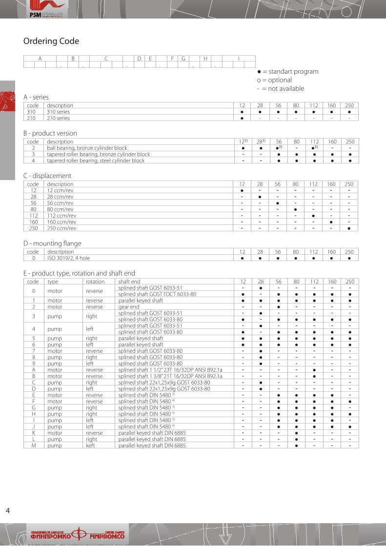
Ordering Code
A B C D E F G H I� � � � � �
● = standart program о = optional - = not availableA - series
code description 12 28 56 80 112 160 250310 310 series ● ● ● ● ● ● ●210 210 series ● - - - - - -
B - product versioncode description 121) 281) 56 80 112 160 250
2 ball bearing, bronze cylinder block ● ● ●2) - ●2) - -3 tapered roller bearing, bronze cylinder block - - ● ● ● ● ●4 tapered roller bearing, steel cylinder block - - ● ● ● ● ●
С - displacementcode description 12 28 56 80 112 160 250
12 12 ccm/rev ● - - - - - -28 28 ccm/rev - ● - - - - -56 56 ccm/rev - - ● - - - -80 80 ccm/rev - - - ● - - -
112 112 ccm/rev - - - - ● - -160 160 ccm/rev - - - - - ● -250 250 ccm/rev - - - - - - ●
D - mounting flangecode description 12 28 56 80 112 160 250
0 ISO 3019/2, 4 hole ● ● ● ● ● ● ●
E - product type, rotation and shaft endcode type rotation shaft end 12 28 56 80 112 160 250
0 motor reverse splined shaft GOST 6033-51 - ● - - - - -splined shaft GOST ГОСТ 6033-80 ● - ● ● ● ● ●
1 motor reverse parallel keyed shaft ● ● ● ● ● ● ●2 motor reverse gear end - - ● - - - -
3 pump right splined shaft GOST 6033-51 - ● - - - - -splined shaft GOST 6033-80 ● - ● ● ● ● ●
4 pump left splined shaft GOST 6033-51 - ● - - - - -splined shaft GOST 6033-80 ● - ● ● ● ● ●
5 pump right parallel keyed shaft ● ● ● ● ● ● ●6 pump left parallel keyed shaft ● ● ● ● ● ● ●7 motor reverse splined shaft GOST 6033-80 - ● - - - - -8 pump right splined shaft GOST 6033-80 - ● - - - - -9 pump left splined shaft GOST 6033-80 - ● - - - - -А motor reverse splined shaft 1 1/2” 23Т 16/32DP ANSI B92�1a - - - - ● - -B motor reverse splined shaft 1 3/8” 21Т 16/32DP ANSI B92�1a - - - - ● - -C pump right splined shaft 22х1,25х9g GOST 6033-80 - ● - - - - -D pump left splined shaft 22х1,25х9g GOST 6033-80 - ● - - - - -E motor reverse splined shaft DIN 5480 3) - - ● ● ● ● -F motor reverse splined shaft DIN 5480 4) - - ● ● ● ● ●G pump right splined shaft DIN 5480 3) - - ● ● ● ● -H pump right splined shaft DIN 5480 4) - - ● ● ● ● ●I pump left splined shaft DIN 5480 3) - - ● ● ● ● -J pump left splined shaft DIN 5480 4) - - ● ● ● ● ●K motor reverse parallel keyed shaft DIN 6885 - - - ● - - -L pump right parallel keyed shaft DIN 6885 - - - ● - - -M pump keft parallel keyed shaft DIN 6885 - - - ● - - -
5
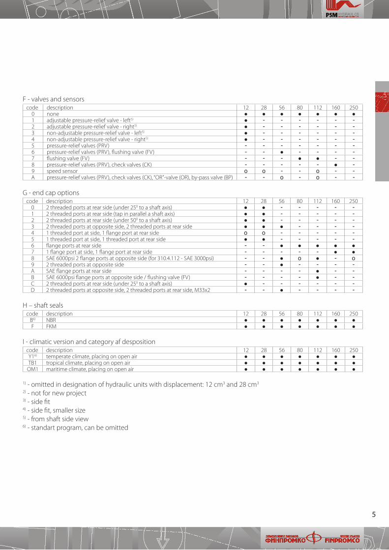
F - valves and sensorscode description 12 28 56 80 112 160 250
0 none ● ● ● ● ● ● ●1 adjustable pressure-relief valve - left5) ● - - - - - -2 adjustable pressure-relief valve - right5) ● - - - - - -3 non-adjustable pressure-relief valve - left5) ● - - - - - -4 non-adjustable pressure-relief valve - right5) ● - - - - - -5 pressure-relief valves (PRV) - - - - - - -6 pressure-relief valves (PRV), flushing valve (FV) - - ● - - - -7 flushing valve (FV) - - - ● ● - -8 pressure-relief valves (PRV), check valves (CK) - - - - - ● -9 speed sensor о о - - о - -А pressure-relief valves (PRV), check valves (CK), “OR”-valve (OR), by-pass valve (BP) - - о - о - -
G - end cap optionscode description 12 28 56 80 112 160 250
0 2 threaded ports at rear side (under 250 to a shaft axis) ● ● - - - - -1 2 threaded ports at rear side (tap in parallel a shaft axis) ● ● - - - - -2 2 threaded ports at rear side (under 500 to a shaft axis) ● ● - - - - -3 2 threaded ports at opposite side, 2 threaded ports at rear side ● ● ● - - - -4 1 threaded port at side, 1 flange port at rear side o o - - - - -5 1 threaded port at side, 1 threaded port at rear side ● ● - - - - -6 flange ports at rear side - - ● ● ● ● ●7 1 flange port at side, 1 flange port at rear side - - - - - ● ●8 SAE 6000psi 2 flange ports at opposite side (for 310�4�112 - SAE 3000psi) - - ● o ● - o9 2 threaded ports at opposite side - - ● - - - -A SAE flange ports at rear side - - - - ● - -B SAE 6000psi flange ports at opposite side / flushing valve (FV) - - - - ● - -C 2 threaded ports at rear side (under 250 to a shaft axis) ● - - - - - -D 2 threaded ports at opposite side, 2 threaded ports at rear side, М33х2 - - ● - - - -
H – shaft sealscode description 12 28 56 80 112 160 250
B6) NBR ● ● ● ● ● ● ●F FKM ● ● ● ● ● ● ●
I - climatic version and category af despositioncode description 12 28 56 80 112 160 250Y16) temperate climate, placing on open air ● ● ● ● ● ● ●ТВ1 tropical climate, placing on open air ● ● ● ● ● ● ●
ОМ1 maritime climate, placing on open air ● ● ● ● ● ● ●
1) - omitted in designation of hydraulic units with displacement: 12 сm3 and 28 сm3
2) - not for new project3) - side fit4) - side fit, smaller size5) - from shaft side view6) - standart program, can be omitted
6
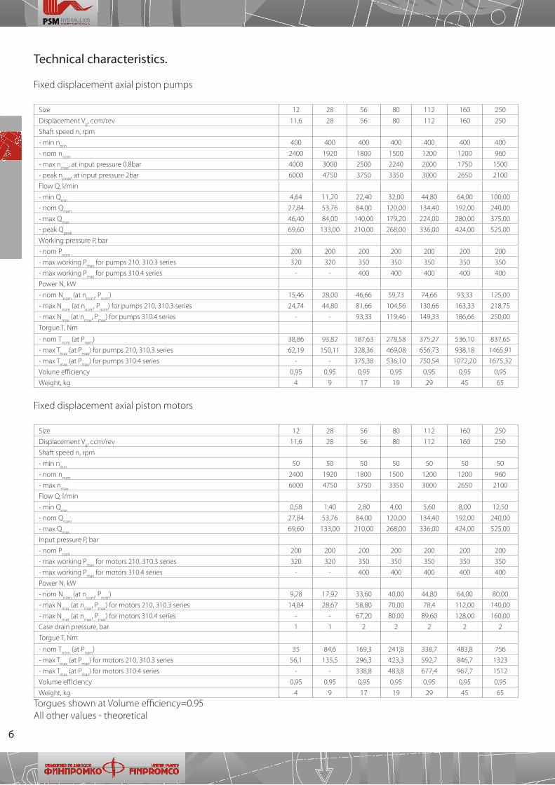
Technical characteristics.
Fixed displacement axial piston pumps
Size 12 28 56 80 112 160 250
Displacement Vg, ccm/rev 11,6 28 56 80 112 160 250
Shaft speed n, rpm
- min nmin
400 400 400 400 400 400 400
- nom nnom
2400 1920 1800 1500 1200 1200 960
- max nmax
, at input pressure 0�8bar 4000 3000 2500 2240 2000 1750 1500
- peak npeak
, at input pressure 2bar 6000 4750 3750 3350 3000 2650 2100
Flow Q, l/min
- min Qmin
4,64 11,20 22,40 32,00 44,80 64,00 100,00
- nom Qnom
27,84 53,76 84,00 120,00 134,40 192,00 240,00
- max Qmax
46,40 84,00 140,00 179,20 224,00 280,00 375,00
- peak Qpeak
69,60 133,00 210,00 268,00 336,00 424,00 525,00
Working pressure P, bar
- nom Pnom
200 200 200 200 200 200 200
- max working Pmax
for pumps 210, 310�3 series 320 320 350 350 350 350 350
- max working Pmax
for pumps 310�4 series - - 400 400 400 400 400
Power N, kW
- nom Nnom
(at nnom
, Pnom
) 15,46 28,00 46,66 59,73 74,66 93,33 125,00
- max Nnom
(at nnom
, Pnom
) for pumps 210, 310�3 series 24,74 44,80 81,66 104,56 130,66 163,33 218,75
- max Nmax
(at nmax
, Pmax
) for pumps 310�4 series - - 93,33 119,46 149,33 186,66 250,00
Torgue T, Nm
- nom Тnom
(at Pnom
) 38,86 93,82 187,63 278,58 375,27 536,10 837,65
- max Tmax
(at Pmax
) for pumps 210, 310�3 series 62,19 150,11 328,36 469,08 656,73 938,18 1465,91
- max Tmax
(at Pmax
) for pumps 310�4 series - - 375,38 536,10 750,54 1072,20 1675,32
Volune efficiency 0,95 0,95 0,95 0,95 0,95 0,95 0,95
Weight, kg 4 9 17 19 29 45 65
Fixed displacement axial piston motors
Size 12 28 56 80 112 160 250
Displacement Vg, ccm/rev 11,6 28 56 80 112 160 250
Shaft speed n, rpm
- min nmin
50 50 50 50 50 50 50
- nom nnom
2400 1920 1800 1500 1200 1200 960
- max nmax
6000 4750 3750 3350 3000 2650 2100
Flow Q, l/min
- min Qmin
0,58 1,40 2,80 4,00 5,60 8,00 12,50
- nom Qnom
27,84 53,76 84,00 120,00 134,40 192,00 240,00
- max Qmax
69,60 133,00 210,00 268,00 336,00 424,00 525,00
Input pressure P, bar
- nom Pnom
200 200 200 200 200 200 200
- max working Pmax
for motors 210, 310�3 series 320 320 350 350 350 350 350
- max working Pmax
for motors 310�4 series - - 400 400 400 400 400
Power N, kW
- nom Nnom
(at nnom
, Pnom
) 9,28 17,92 33,60 40,00 44,80 64,00 80,00
- max Nmax
(at nmax
, Pmax
) for motors 210, 310�3 series 14,84 28,67 58,80 70,00 78,4 112,00 140,00
- max Nmax
(at nmax
, Pmax
) for motors 310�4 series - - 67,20 80,00 89,60 128,00 160,00
Case drain pressure, bar 1 1 2 2 2 2 2
Torgue T, Nm
- nom Тnom
(at Pnom
) 35 84,6 169,3 241,8 338,7 483,8 756
- max Tmax
(at Pmax
) for motors 210, 310�3 series 56,1 135,5 296,3 423,3 592,7 846,7 1323
- max Tmax
(at Pmax
) for motors 310�4 series - - 338,8 483,8 677,4 967,7 1512
Volume efficiency 0,95 0,95 0,95 0,95 0,95 0,95 0,95
Weight, kg 4 9 17 19 29 45 65
Torgues shown at Volume efficiency=0�95All other values - theoretical
7
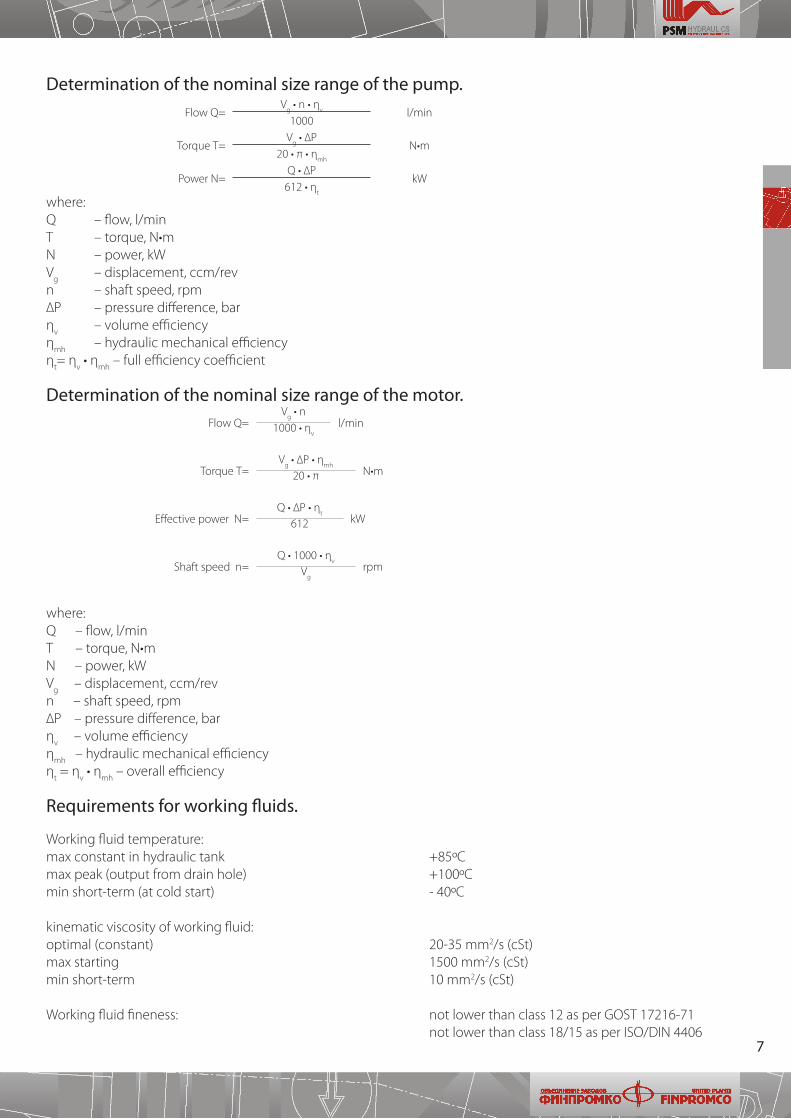
Determination of the nominal size range of the pump.
Flow Q=V
g • n • η
v l/min1000
Torque Т=V
g • ∆P
N•m20 • π • η
mh
Power N=Q • ∆P
kW612 • η
t
where:Q – flow, l/minТ – torque, N•mN – power, kWV
g – displacement, ccm/rev
n – shaft speed, rpm∆P – pressure difference, barη
v – volume efficiency
ηmh
– hydraulic mechanical efficiencyη
t= η
v • η
mh – full efficiency coefficient
Determination of the nominal size range of the motor. Flow Q=
Vg • n
l/min1000 • ηv
Torque Т=V
g • ∆P • η
mhN•m20 • π
Effective power N=Q • ∆P • η
tkW612
Shaft speed n=Q • 1000 • η
vrpmV
g
where:Q – flow, l/minТ – torque, N•mN – power, kWV
g – displacement, ccm/rev
n – shaft speed, rpm∆P – pressure difference, barη
v – volume efficiency
ηmh
– hydraulic mechanical efficiencyη
t = η
v • η
mh – overall efficiency
Requirements for working fluids.
Working fluid temperature:max constant in hydraulic tank +85ºСmax peak (output from drain hole) +100ºСmin short-term (at cold start) - 40ºС
kinematic viscosity of working fluid:optimal (constant) 20-35 mm2/s (cSt)max starting 1500 mm2/s (cSt)min short-term 10 mm2/s (cSt)
Working fluid fineness: not lower than class 12 as per GOST 17216-71 not lower than class 18/15 as per ISO/DIN 4406
8
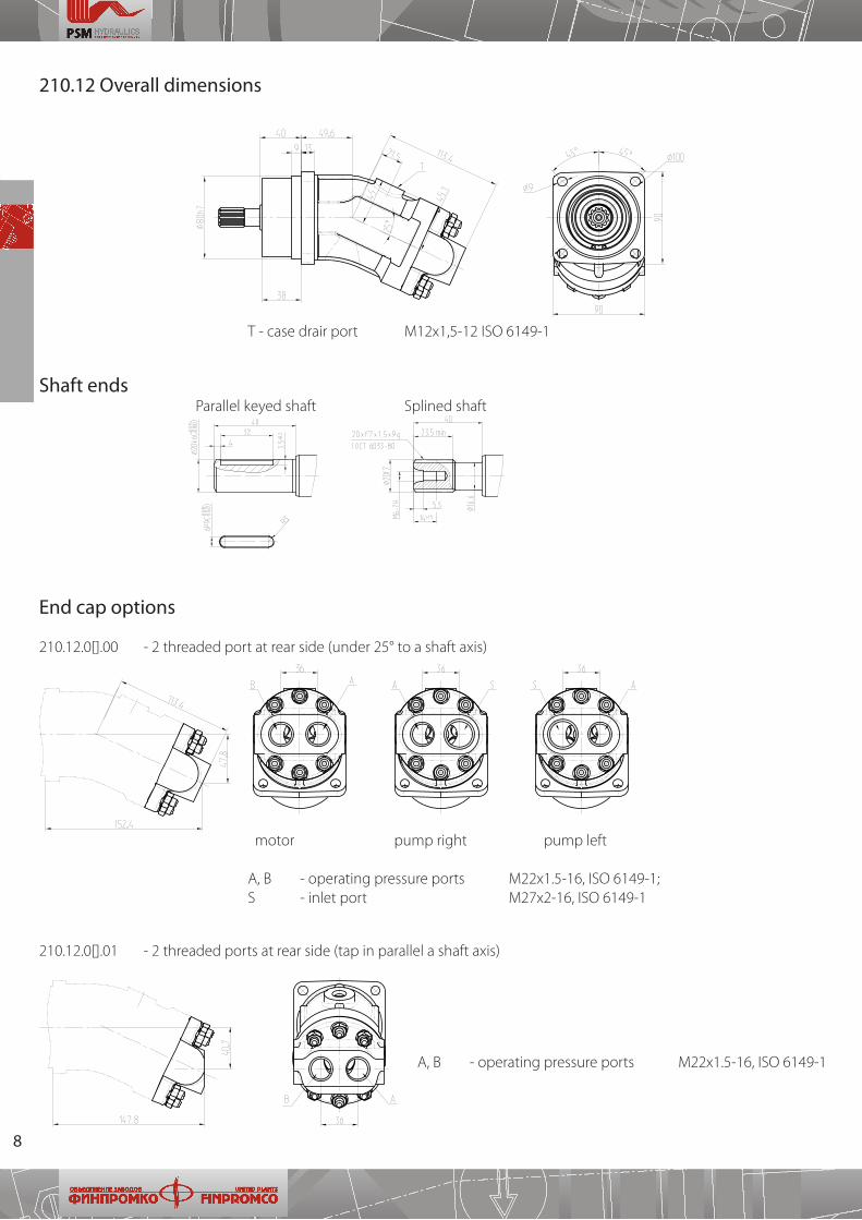
210.12 Overall dimensions
End cap options
210�12�0[]�00 - 2 threaded port at rear side (under 25° to a shaft axis)
210�12�0[]�01 - 2 threaded ports at rear side (tap in parallel a shaft axis)
motor pump right pump left
А, В - operating pressure ports М22х1�5-16, ISO 6149-1; S - inlet port М27х2-16, ISO 6149-1
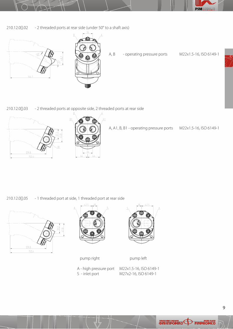
А, В - operating pressure ports М22х1�5-16, ISO 6149-1
Shaft ends Parallel keyed shaft Splined shaft
Т - case drair port М12х1,5-12 ISO 6149-1
9
210�12�0[]�05 - 1 threaded port at side, 1 threaded port at rear side
А, В - operating pressure ports М22х1�5-16, ISO 6149-1
А, А1, В, В1 - operating pressure ports М22х1�5-16, ISO 6149-1
pump right pump left
А - high pressure port М22х1�5-16, ISO 6149-1 S - inlet port М27х2-16, ISO 6149-1
210�12�0[]�03 - 2 threaded ports at opposite side, 2 threaded ports at rear side
210�12�0[]�02 - 2 threaded ports at rear side (under 50° to a shaft axis)
10
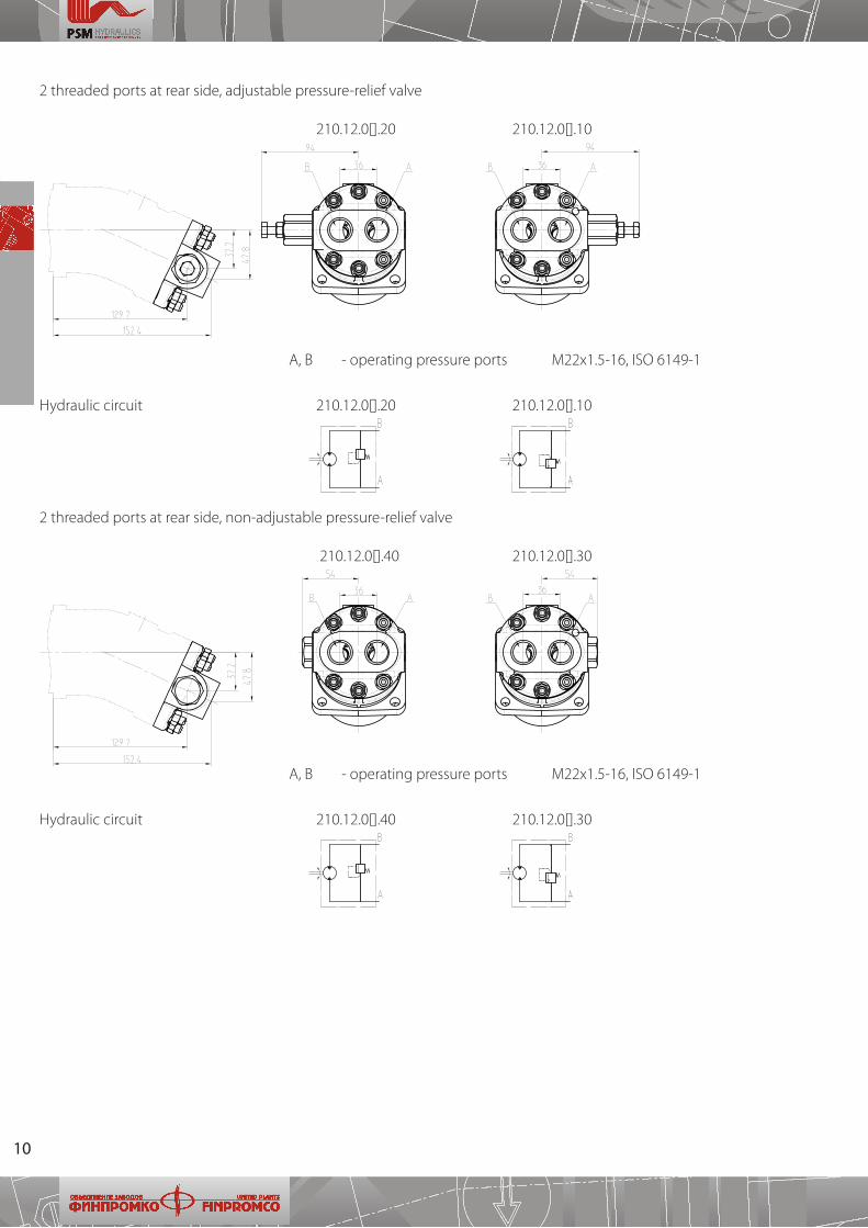
2 threaded ports at rear side, non-adjustable pressure-relief valve
210�12�0[]�40 210�12�0[]�30
2 threaded ports at rear side, adjustable pressure-relief valve
210�12�0[]�20 210�12�0[]�10
А, B - operating pressure ports М22х1�5-16, ISO 6149-1
А, B - operating pressure ports М22х1�5-16, ISO 6149-1
Hydraulic circuit 210�12�0[]�20 210�12�0[]�10
Hydraulic circuit 210�12�0[]�40 210�12�0[]�30

11
Notes
12
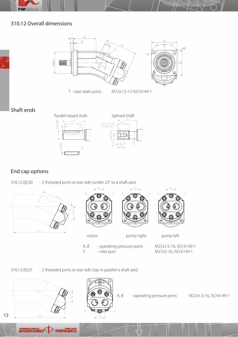
310�12�0[]�01 - 2 threaded ports at rear side (tap in parallel a shaft axis)
End cap options
310�12�0[]�00 - 2 threaded ports at rear side (under 25° to a shaft axis)
310.12 Overall dimensions
Shaft ends Parallel keyed shaft Splined shaft
motor pump right pump left
А, В - operating pressure ports М22х1�5-16, ISO 6149-1 S - inlet port М27х2-16, ISO 6149-1
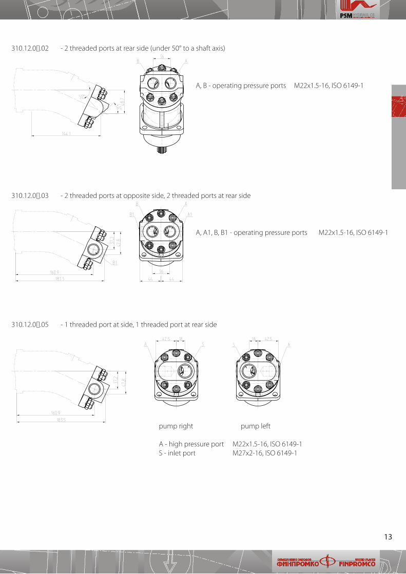
А, B - operating pressure ports М22х1�5-16, ISO 6149-1
Т - case drain ports М12х1,5-12 ISO 6149-1
13
310�12�0[]�05 - 1 threaded port at side, 1 threaded port at rear side
А, B - operating pressure ports М22х1�5-16, ISO 6149-1
А, A1, B, B1 - operating pressure ports М22х1�5-16, ISO 6149-1
pump right pump left
А - high pressure port М22х1�5-16, ISO 6149-1 S - inlet port М27х2-16, ISO 6149-1
310�12�0[]�03 - 2 threaded ports at opposite side, 2 threaded ports at rear side
310�12�0[]�02 - 2 threaded ports at rear side (under 50° to a shaft axis)
14
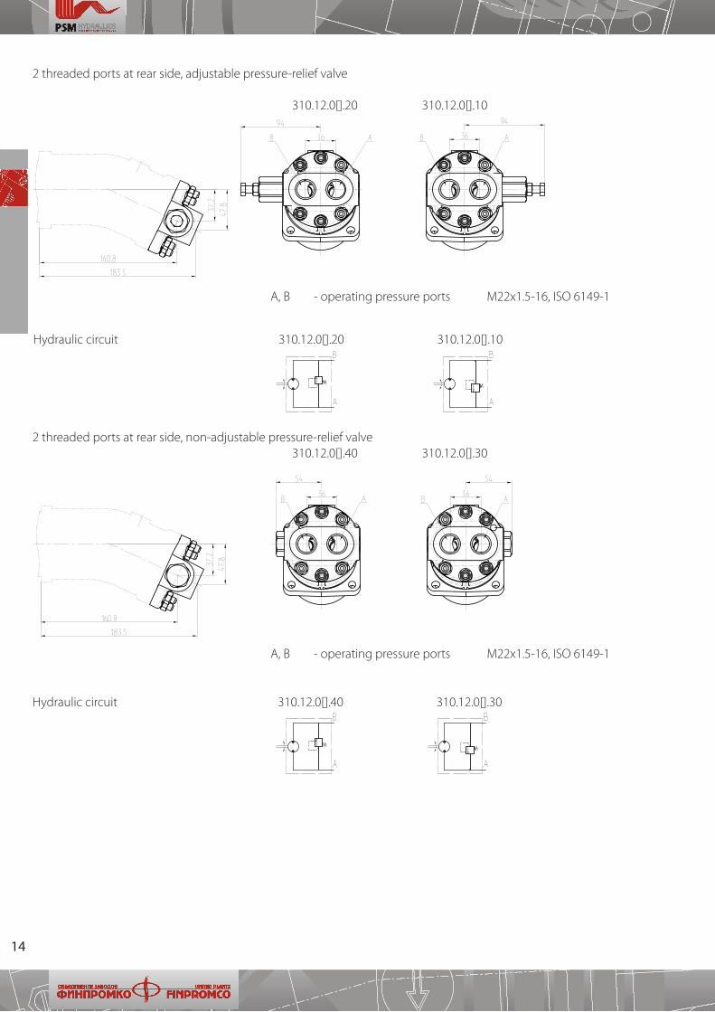
2 threaded ports at rear side, non-adjustable pressure-relief valve 310�12�0[]�40 310�12�0[]�30
А, B - operating pressure ports М22х1�5-16, ISO 6149-1
А, B - operating pressure ports М22х1�5-16, ISO 6149-1
2 threaded ports at rear side, adjustable pressure-relief valve
310�12�0[]�20 310�12�0[]�10
Hydraulic circuit 310�12�0[]�20 310�12�0[]�10
Hydraulic circuit 310�12�0[]�40 310�12�0[]�30
15
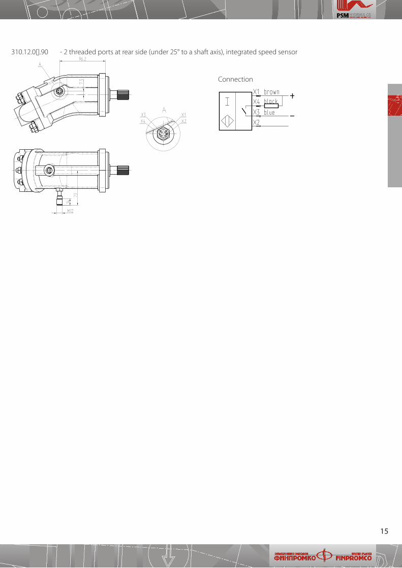
310�12�0[]�90 - 2 threaded ports at rear side (under 25° to a shaft axis), integrated speed sensor
Connection
16
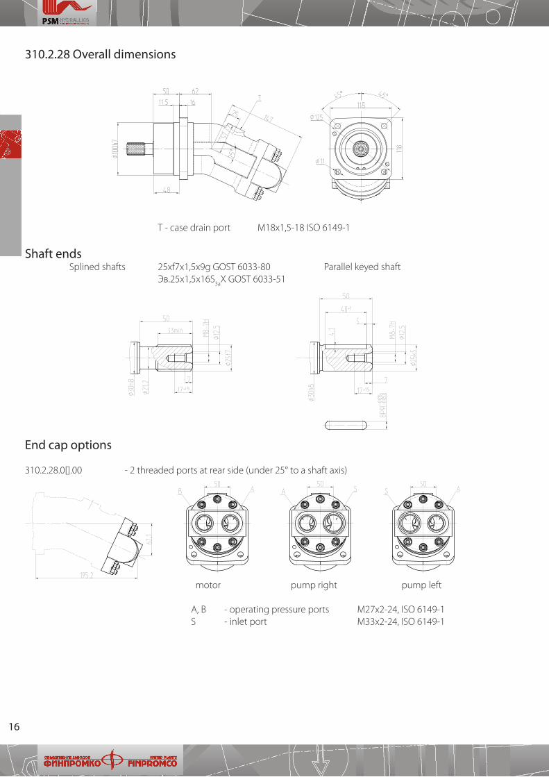
310.2.28 Overall dimensions
Shaft ends Splined shafts 25хf7x1,5x9g GOST 6033-80 Parallel keyed shaft Эв�25x1,5x16S
3aX GOST 6033-51
End cap options
310�2�28�0[]�00 - 2 threaded ports at rear side (under 25° to a shaft axis)
Т - case drain port М18х1,5-18 ISO 6149-1
motor pump right pump left
А, B - operating pressure ports М27х2-24, ISO 6149-1 S - inlet port M33x2-24, ISO 6149-1
17
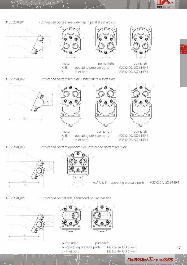
310�2�28�0[]�03 - 2 threaded ports at opposite side, 2 threaded ports at rear side
310�2�28�0[]�01 - 2 threaded ports at rear side (tap in parallel a shaft axis)
310�2�28�0[]�02 - 2 threaded ports at rear side (under 50° to a shaft axis)
310�2�28�0[]�05 - 1 threaded port at side, 1 threaded port at rear side
А, А1, B, В1 - operating pressure ports М27х2-24, ISO 6149-1
pump right pump left А - operating pressure ports М27х2-24, ISO 6149-1 S - inlet port M33x2-24, ISO 6149-1
motor pump right pump left А, B - operating pressure ports М27х2-20, ISO 6149-1 S - inlet port M33x2-20, ISO 6149-1
motor pump right pump left А, B - operating pressure ports М27х2-20, ISO 6149-1 S - inlet port M33x2-20, ISO 6149-1
18
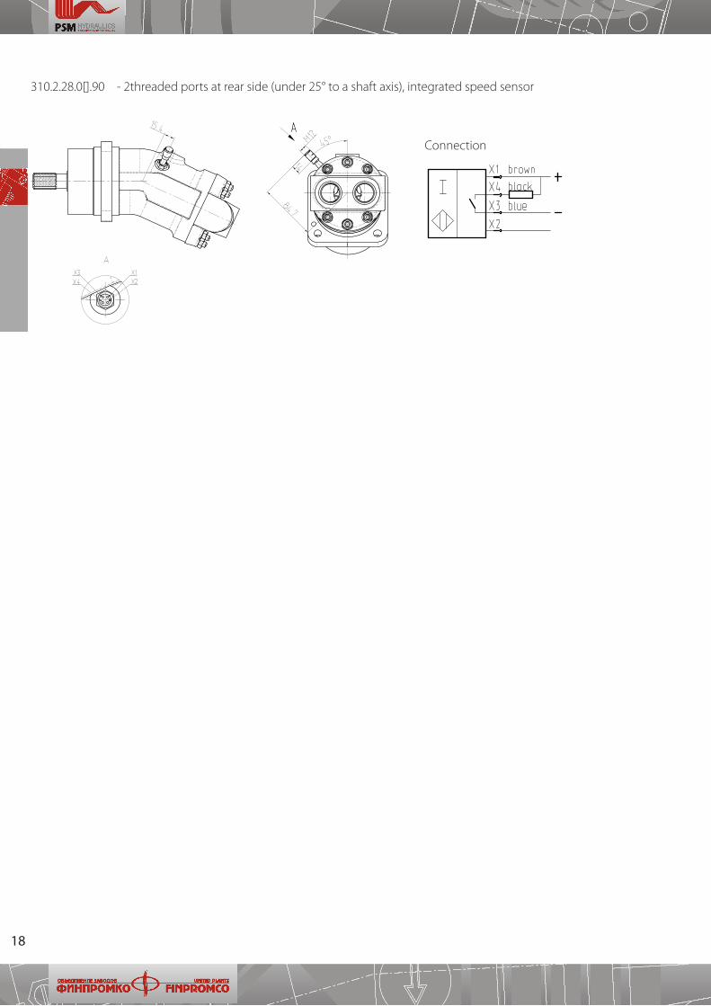
310�2�28�0[]�90 - 2threaded ports at rear side (under 25° to a shaft axis), integrated speed sensor
Connection

19
Notes
20
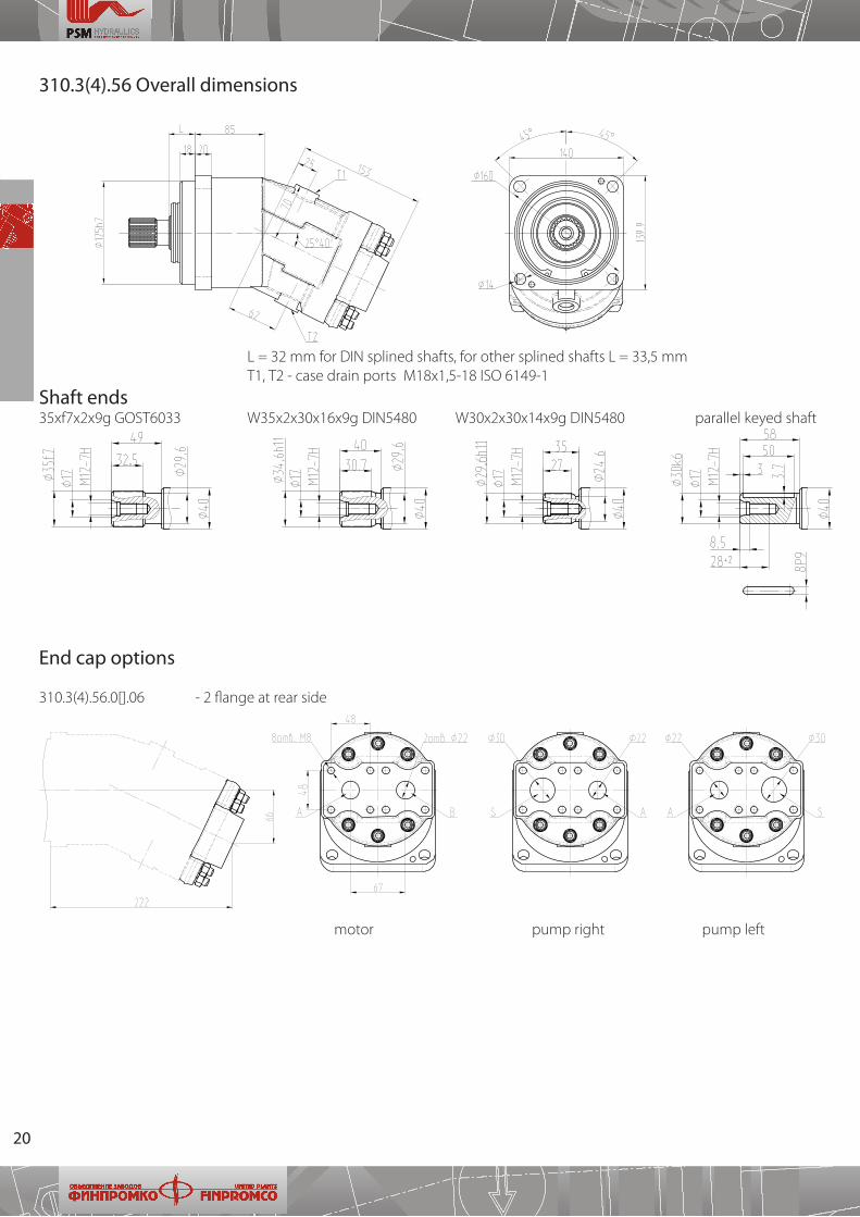
310.3(4).56 Overall dimensions
Shaft ends35xf7x2x9g GOST6033 W35x2x30x16x9g DIN5480 W30x2x30x14x9g DIN5480 parallel keyed shaft
End cap options
310�3(4)�56�0[]�06 - 2 flange at rear side
motor pump right pump left
L = 32 mm for DIN splined shafts, for other splined shafts L = 33,5 mm Т1, Т2 - case drain ports М18х1,5-18 ISO 6149-1
21
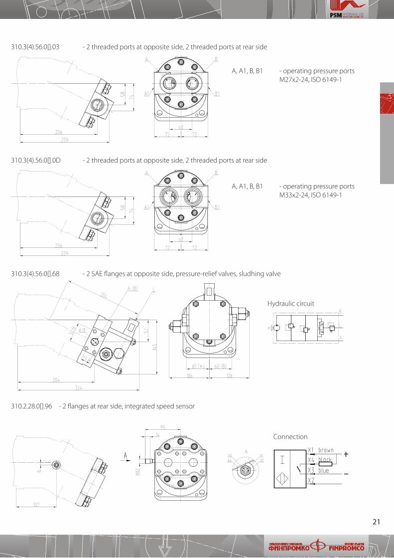
310�3(4)�56�0[]�03 - 2 threaded ports at opposite side, 2 threaded ports at rear side
310�3(4)�56�0[]�0D - 2 threaded ports at opposite side, 2 threaded ports at rear side
А, А1, B, В1 - operating pressure ports М27х2-24, ISO 6149-1
А, А1, B, В1 - operating pressure ports М33х2-24, ISO 6149-1
310�3(4)�56�0[]�68 - 2 SAE flanges at opposite side, pressure-relief valves, sludhing valve
Hydraulic circuit
310�2�28�0[]�96 - 2 flanges at rear side, integrated speed sensor
Connection
22
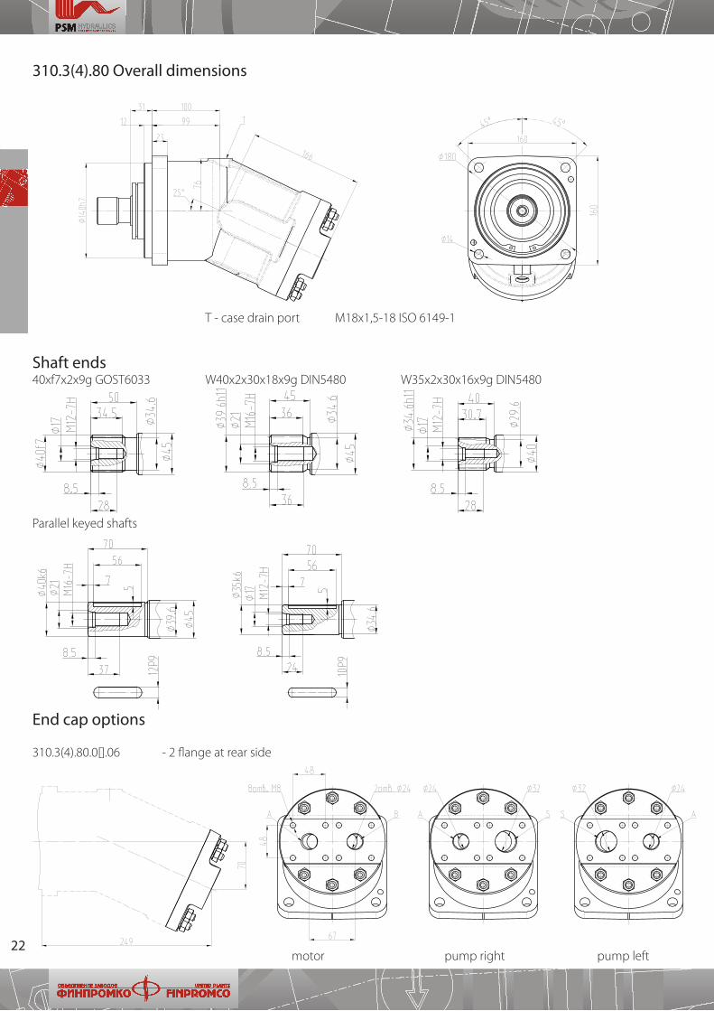
310.3(4).80 Overall dimensions
Shaft ends40xf7x2x9g GOST6033 W40x2x30x18x9g DIN5480 W35x2x30x16x9g DIN5480
End cap options
310�3(4)�80�0[]�06 - 2 flange at rear side
motor pump right pump left
Т - case drain port М18х1,5-18 ISO 6149-1
Parallel keyed shafts
23
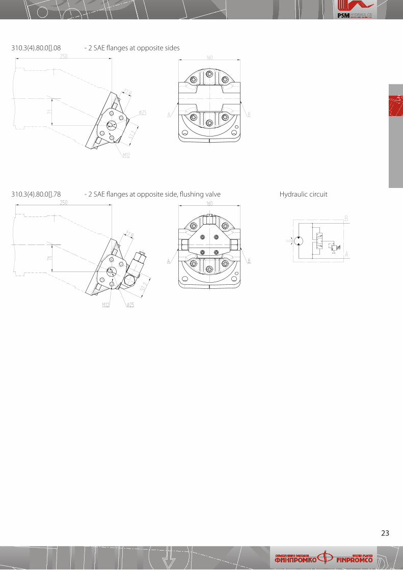
310�3(4)�80�0[]�08 - 2 SAE flanges at opposite sides
310�3(4)�80�0[]�78 - 2 SAE flanges at opposite side, flushing valve Hydraulic circuit
24
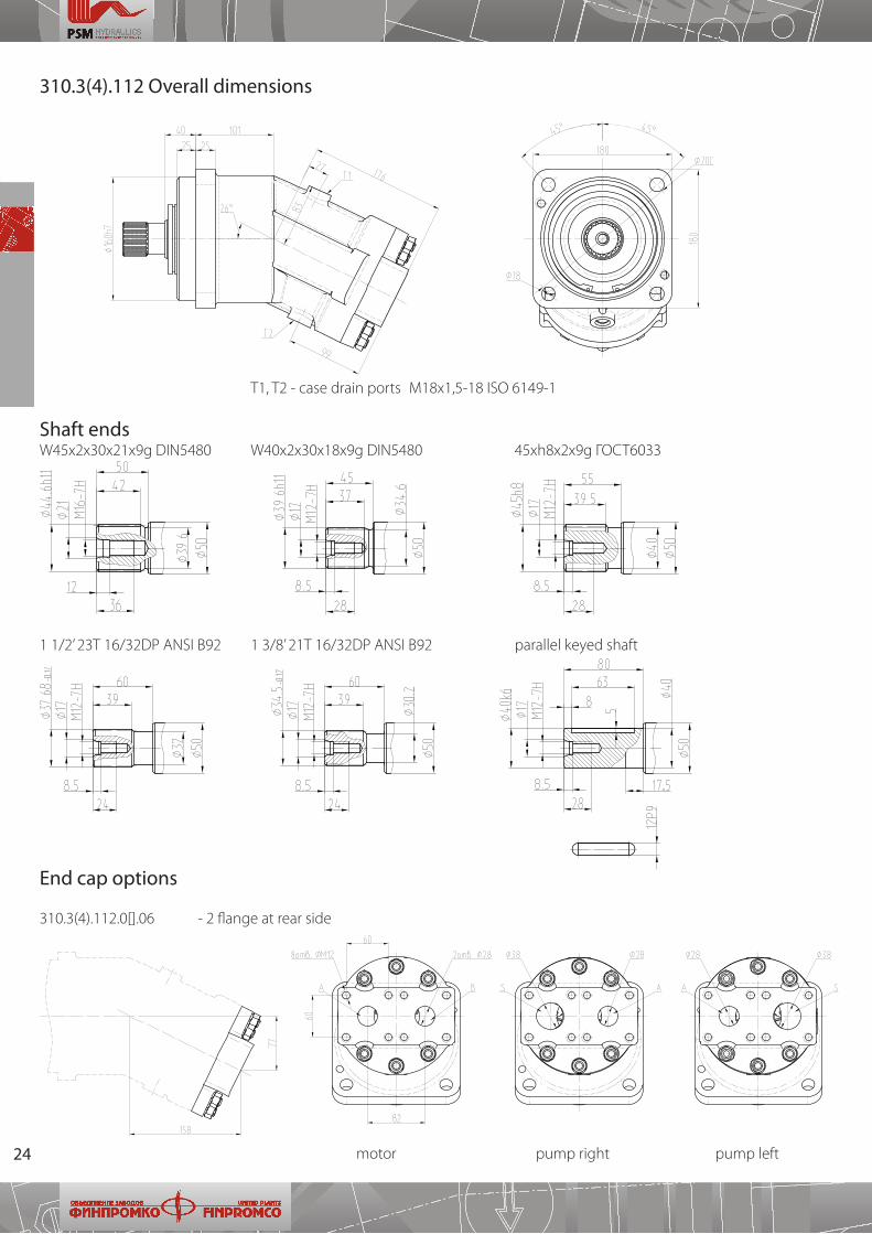
310.3(4).112 Overall dimensions
Shaft endsW45x2x30x21x9g DIN5480 W40x2x30x18x9g DIN5480 45xh8x2x9g ГОСТ6033
End cap options
310�3(4)�112�0[]�06 - 2 flange at rear side
Т1, T2 - case drain ports М18х1,5-18 ISO 6149-1
motor pump right pump left
1 1/2’ 23T 16/32DP ANSI B92 1 3/8’ 21T 16/32DP ANSI B92 parallel keyed shaft
25
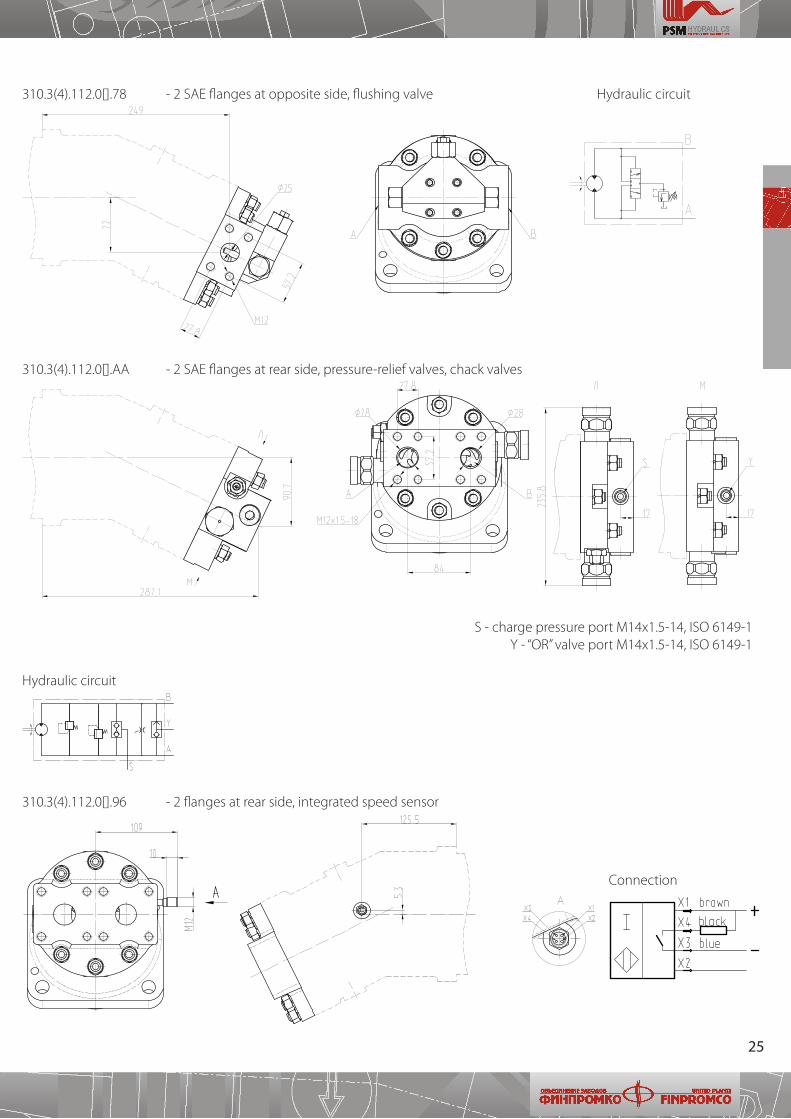
310�3(4)�112�0[]�78 - 2 SAE flanges at opposite side, flushing valve Hydraulic circuit
310�3(4)�112�0[]�АА - 2 SAE flanges at rear side, pressure-relief valves, chack valves
Hydraulic circuit
S - charge pressure port М14х1�5-14, ISO 6149-1Y - “OR” valve port М14х1�5-14, ISO 6149-1
310�3(4)�112�0[]�96 - 2 flanges at rear side, integrated speed sensor
Connection
26
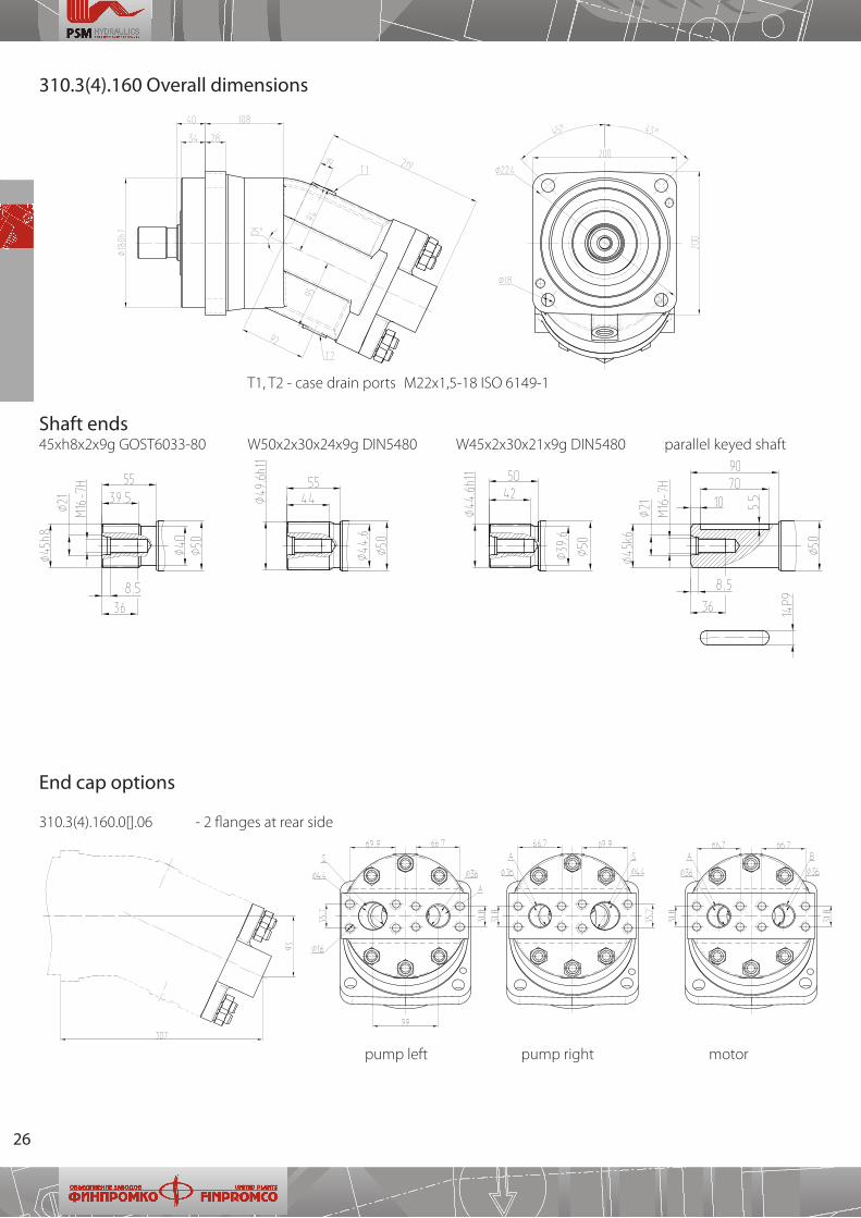
310.3(4).160 Overall dimensions
Shaft ends45хh8x2x9g GOST6033-80 W50x2x30x24x9g DIN5480 W45x2x30x21x9g DIN5480 parallel keyed shaft
End cap options
310�3(4)�160�0[]�06 - 2 flanges at rear side
Т1, T2 - case drain ports М22х1,5-18 ISO 6149-1
pump left pump right motor
27
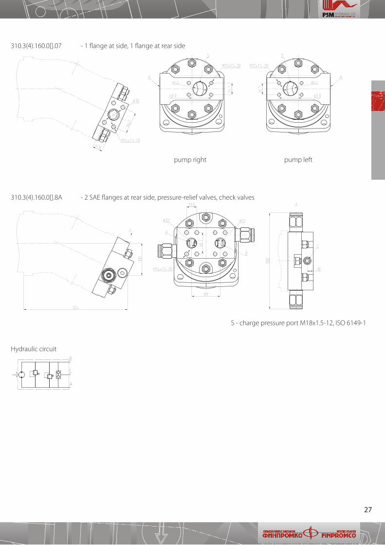
310�3(4)�160�0[]�07 - 1 flange at side, 1 flange at rear side
310�3(4)�160�0[]�8А - 2 SAE flanges at rear side, pressure-relief valves, check valves
Hydraulic circuit
pump right pump left
S - charge pressure port М18x1�5-12, ISO 6149-1
28
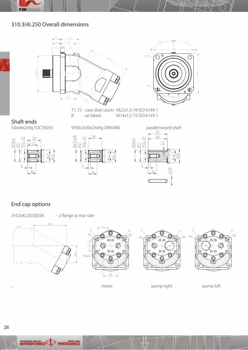
310.3(4).250 Overall dimensions
Shaft ends50хh8x2x9g ГОСТ6033 W50x2x30x24x9g DIN5480 parallel keyed shaft
End cap options
310�3(4)�250�0[]�06 - 2 flange at rear side
Т1, T2 - case drain ports М22х1,5-18 ISO 6149-1 R - air bleed М14х1,5-15 ISO 6149-1
��� motor pump right pump left
29
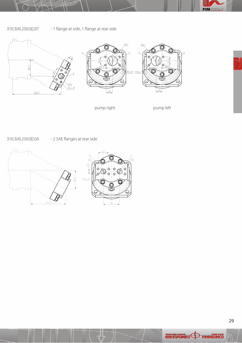
310�3(4)�250�0[]�07 - 1 flange at side, 1 flange at rear side
310�3(4)�250�0[]�0А - 2 SAE flanges at rear side
pump right pump left

Fixed displacement axial pistonpumps and motors
series
TECHNICAL CATALOGUE
310
PSM-HYDRAULICS
20 11