Embed Size (px)
Citation preview
17
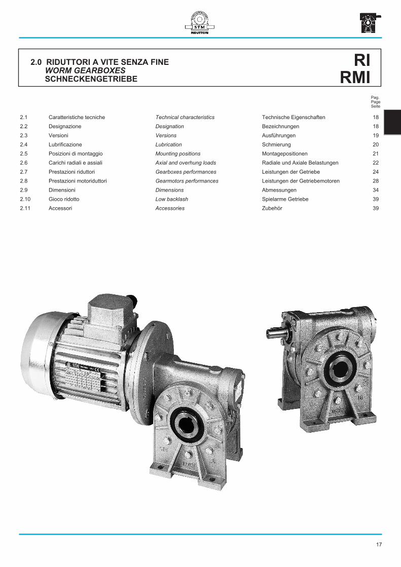
2.0 RIDUTTORI A VITE SENZA FINE
WORM GEARBOXES
SCHNECKENGETRIEBE
RI
RMI
2.1 Caratteristiche tecniche Technical characteristics Technische Eigenschaften 18
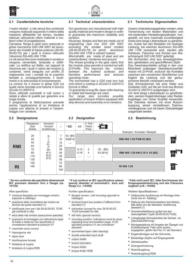
2.2 Designazione Designation Bezeichnungen 18
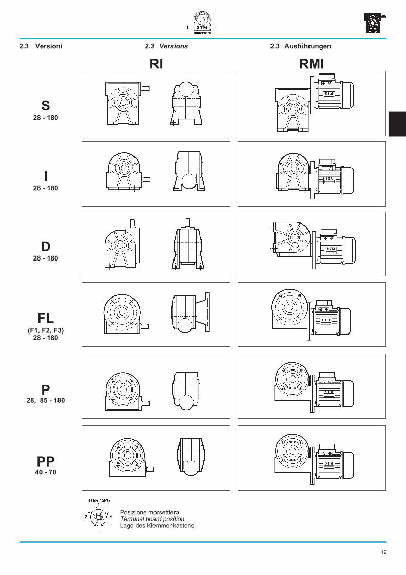
2.3 Versioni Versions Ausführungen 19
2.4 Lubrificazione Lubrication Schmierung 20
2.5 Posizioni di montaggio Mounting positions Montagepositionen 21
2.6 Carichi radiali e assiali Axial and overhung loads Radiale und Axiale Belastungen 22
2.7 Prestazioni riduttori Gearboxes performances Leistungen der Getriebe 24
2.8 Prestazioni motoriduttori Gearmotors performances Leistungen der Getriebemotoren 28
2.9 Dimensioni Dimensions Abmessungen 34
2.10 Gioco ridotto Low backlash Spielarme Getriebe 39
2.11 Accessori Accessories Zubehör 39
Pag.PageSeite
18
I nostri riduttori a vite senza fine combinativengono realizzati seguendo il criterio dellamassima affidabilità nel tempo, risultatoottenuto utilizzando ottimi materiali e mo-derni criteri di progettazione.Carcasse, flange e piedi sono realizzati inghisa meccanica G20 UNI 5007 ad esclu-sione dei modelli di bassa potenza (28-40-50-63-70) per i quali è invece utilizzatol’alluminio SG-AlSi UNI 1706.Le viti senza fine sono realizzate in acciaio evengono cementate, temprate e rettifi-cate. La rettifica sul filetto, nei rapporti diriduzione per i quali il valore del modulo loconsente, viene eseguita con profilo ZImigliorando così i contatti tra le superficidentate e, conseguentemente, il rendi-mento e la silenziosità di funzionamento.La corona ha il mozzo in ghisa G20 sulquale viene riportata una fusione in bronzoGCuSn12 UNI7013.Sono utilizzati cuscinetti a rulli conici oradiali a sfere di qualità per garantire unalunga durata.Il programma di fabbricazione prevedeanche, l’applicazione di un limitatore dicoppia con allarme di arresto e l’assem-blaggio con variatore.
Our gearboxes are manufactured with highquality material and modern design in orderto guarantee the maximum reliability andduration.Housings, flanges and feet are made out ofengineering cast iron G20 UNI 5007excluding the smaller sized models(28-40-50-63-70) for which aluminiumSG-AlSi UNI 1706 is utilized instead.Wormshafts are made of steel and arecasehardened, hardened and ground.The thread grinding in the gear ratios thatthe module value permits is carried out withZI-Profile. This improves the contactbetween the toothed surfaces andtherefore performance and reducesoperating noise.The wormwheel has a G20 cast iron hubonto which a casting in GCsSn12 UNI7013bronze is fitted.To guarantee a long life, taper roller bearingor radial ball bearings are used.Our range also provides possibleapplication of torque limiters equipped withstop devices and assembly on to variators.
Unsere Untersetzungsgetriebe werden unterVerwendung von besten Materialien undmit modernsten Herstellungsmethoden her-gestellt, um eine maximale Zuverlässigkeitsowie eine lange Lebensdauer zu garantie-ren. Außer bei den Modellen mit niedrigerLeistung, bei welchen Aluminium SG-AlSiUNI 1706 verwendet wird, werden alleGehäuse, Flansche und Sockel aus Ma-schinenguß G20 UNI 5007 gefertigt.Die Schnecken sind aus einsatzgehärte-tem, gehärtetem und geschliffenem Stahl.Das Gewindeschleifen erfolgt in den vomModulwert zulässigen Übersetzunsverhält-nissen mit ZI-Profil, wodurch die Kontaktezwischen den verzahnten Oberflächen undfolglich die Leistung und der geräu-scharme Betrieb verbessert werden.Das Schneckenrad hat eine Nabe ausGußeisen G20, auf die ein Guß aus BronzeGcuSn12 UNI7013 aufgetragen wird.Um eine lange Lebensdauer zu gewährlei-sten, werden Kegelrollenlager oder Radial-kugellager von hoher Qualität verwendet.Die Getriebe können mit einer Rutsch-kupplung, einem einstellbaren Drehmo-mentbegrenzer und mit einem Drehzahlreglerausgerüstet werden.
2.1 Technical characteristics 2.1 Technische Eigenschaften2.1 Caratteristiche tecniche
2.2 Designation2.2 Designazione 2.2 Bezeichnung
* If not conform to IEC specifications please
specify diameter of wormshaft’s bore and
flange (i.e. :14/200)
Further specification:
• flanged version. Left mounting opposite tocatalogue
• terminal board box position if different fromstandard (1)
• lubrication (except for size 28,40,50,63,70,85 lubricated for life)
• left helix (special version)
• mounting position. Indications must be givenregarding level and breather plugs. If notspecified positions 01 are consideredstandard
• wormwheel taper roller bearings
• double extended input shaft
• output shafts
• forzed lubrication
• torque limiter
• torque limiter RDB
* Falls nicht nach IEC, bitte Durchmesser der
Eingangswellenbohrung und des Flansches
angeben (z.B.: 14/200)
Weitere Spezifikationen:
• Geflanschte Ausführung mit Montage links(nicht wie im Katalog)
• Stellung des Klemmenkastens des Motors,falls diese von der Standard- Ausführungabweicht (1)
• Schmiermittelfüllung (außer bei denwartungsfreien Typen 28,40,50,63,70,85)
• Linksgängige Schraubenlinie der Schnek- ke(Spezialausführung)
• Montagestellung mit Angabe der Ölpegel undEntlüfterstöpsel. Falls nicht andersangegeben, gelten die Pos. 01 als Standard.
• Kegelrollenlager auf der Schnecke
• Beidseitige Zapfen auf Eingangswelle
• Abtriebswellen
• Zwangsschmierung
• Rutschkupplung
• Rutschkupplung RDB
* Se non conforme alle specifiche dimensionali
IEC precisare diametro foro e flangia (es.
14/120)
Altre specifiche:
• Versione flangiata con montaggio sinistro(opposto a catalogo)
• posizione della morsettiera del motore sediversa da quella standard (1)
• lubrificante (non per i tipi 28,40,50,63, 70,85già lubrificati a vita)
• elica della vite sinistra (esecuzione speciale)
• posizione di montaggio con indicazione tappidi livello e sfiato;se non specificato siconsiderano standard le posizioni 01
• cuscinetti conici corona
• bisporgenza vite
• alberi lenti
• lubrificazione forzata
• limitatore di coppia
• limitatore di coppia RDB
GrandezzaSize
Größe
VersioneVersion
Ausführungi * IEC kW
n° PoliPolesPolig
SIDFLP
PP(F1)(F2)(F3)
Esempio / Example / Beispiel
RMI
28 7 63 (B5)
40 10 63(B14) RMI 40S 1:20 PAM 63 (B5)
50 15 ....
63 20
70 28 0.13 2 63 (B5)
85 40 0.18 4 63 (B14) RMI 40S 1:20 kW 0.18 4 63 (B5)
110 49 .... .... ....
130 56
RI
150 70
180 80 RI 40S 1:20
100
19
2.3 Versions 2.3 Ausführungen2.3 Versioni
RMIRI
I
D
FL
P
PP
28 - 180
(F1, F2, F3)
28 - 180
28, 85 - 180
40 - 70
28 - 180
Posizione morsettieraTerminal board positionLage des Klemmenkastens
S28 - 180
20
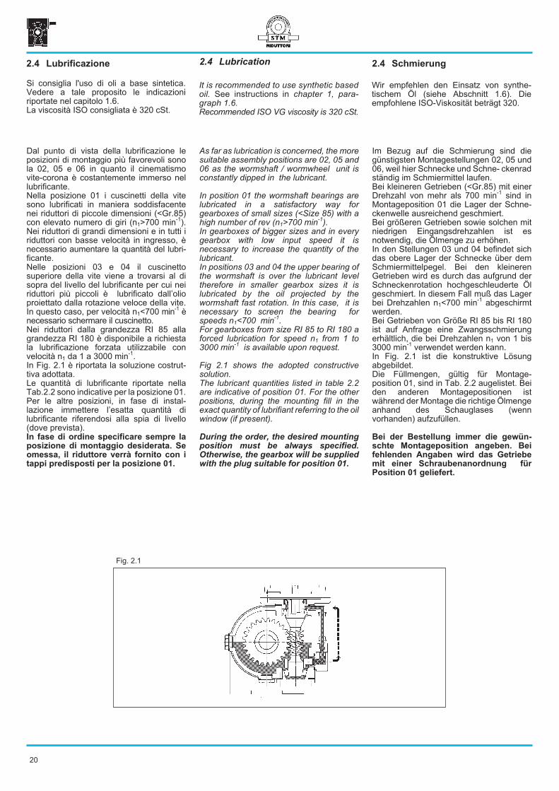
Fig. 2.1
As far as lubrication is concerned, the moresuitable assembly positions are 02, 05 and06 as the wormshaft / wormwheel unit isconstantly dipped in the lubricant.
In position 01 the wormshaft bearings arelubricated in a satisfactory way forgearboxes of small sizes (<Size 85) with ahigh number of rev (n1>700 min
-1).
In gearboxes of bigger sizes and in everygearbox with low input speed it isnecessary to increase the quantity of thelubricant.In positions 03 and 04 the upper bearing ofthe wormshaft is over the lubricant leveltherefore in smaller gearbox sizes it islubricated by the oil projected by thewormshaft fast rotation. In this case, it isnecessary to screen the bearing forspeeds n1<700 min
-1.
For gearboxes from size RI 85 to RI 180 aforced lubrication for speed n1 from 1 to3000 min
-1is available upon request.
Fig 2.1 shows the adopted constructivesolution.The lubricant quantities listed in table 2.2are indicative of position 01. For the otherpositions, during the mounting fill in theexact quantity of lubrifiant referring to the oilwindow (if present).
During the order, the desired mounting
position must be always specified.
Otherwise, the gearbox will be supplied
with the plug suitable for position 01.
Im Bezug auf die Schmierung sind diegünstigsten Montagestellungen 02, 05 und06, weil hier Schnecke und Schne- ckenradständig im Schmiermittel laufen.Bei kleineren Getrieben (<Gr.85) mit einerDrehzahl von mehr als 700 min
-1sind in
Montageposition 01 die Lager der Schne-ckenwelle ausreichend geschmiert.Bei größeren Getrieben sowie solchen mitniedrigen Eingangsdrehzahlen ist esnotwendig, die Ölmenge zu erhöhen.In den Stellungen 03 und 04 befindet sichdas obere Lager der Schnecke über demSchmiermittelpegel. Bei den kleinerenGetrieben wird es durch das aufgrund derSchneckenrotation hochgeschleuderte Ölgeschmiert. In diesem Fall muß das Lagerbei Drehzahlen n1<700 min
-1abgeschirmt
werden.Bei Getrieben von Größe RI 85 bis RI 180ist auf Anfrage eine Zwangsschmierungerhältlich, die bei Drehzahlen n1 von 1 bis3000 min
-1verwendet werden kann.
In Fig. 2.1 ist die konstruktive Lösungabgebildet.Die Füllmengen, gültig für Montage-position 01, sind in Tab. 2.2 augelistet. Beiden anderen Montagepositionen istwährend der Montage die richtige Ölmengeanhand des Schauglases (wennvorhanden) aufzufüllen.
Bei der Bestellung immer die gewün-
schte Montageposition angeben. Bei
fehlenden Angaben wird das Getriebe
mit einer Schraubenanordnung für
Position 01 geliefert.
2.4 Lubrication2.4 Lubrificazione 2.4 Schmierung
Dal punto di vista della lubrificazione leposizioni di montaggio più favorevoli sonola 02, 05 e 06 in quanto il cinematismovite-corona è costantemente immerso nellubrificante.Nella posizione 01 i cuscinetti della vitesono lubrificati in maniera soddisfacentenei riduttori di piccole dimensioni (<Gr.85)con elevato numero di giri (n1>700 min
-1).
Nei riduttori di grandi dimensioni e in tutti iriduttori con basse velocità in ingresso, ènecessario aumentare la quantità del lubri-ficante.Nelle posizioni 03 e 04 il cuscinettosuperiore della vite viene a trovarsi al disopra del livello del lubrificante per cui neiriduttori più piccoli è lubrificato dall’olioproiettato dalla rotazione veloce della vite.In questo caso, per velocità n1<700 min
-1è
necessario schermare il cuscinetto.Nei riduttori dalla grandezza RI 85 allagrandezza RI 180 è disponibile a richiestala lubrificazione forzata utilizzabile convelocità n1 da 1 a 3000 min
-1.
In Fig. 2.1 è riportata la soluzione costrut-tiva adottata.Le quantità di lubrificante riportate nellaTab.2.2 sono indicative per la posizione 01.Per le altre posizioni, in fase di instal-lazione immettere l’esatta quantità dilubrificante riferendosi alla spia di livello(dove prevista).In fase di ordine specificare sempre la
posizione di montaggio desiderata. Se
omessa, il riduttore verrà fornito con i
tappi predisposti per la posizione 01.
Si consiglia l'uso di oli a base sintetica.Vedere a tale proposito le indicazioniriportate nel capitolo 1.6.La viscosità ISO consigliata è 320 cSt.
It is recommended to use synthetic basedoil. See instructions in chapter 1, para-graph 1.6.Recommended ISO VG viscosity is 320 cSt.
Wir empfehlen den Einsatz von synthe-tischem Öl (siehe Abschnitt 1.6). Dieempfohlene ISO-Viskosität beträgt 320.
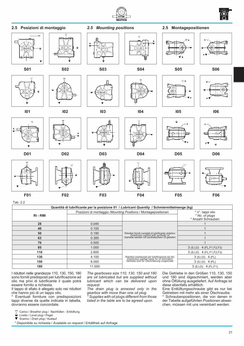
2.5 Mounting positions2.5 Posizioni di montaggio 2.5 Montagepositionen
Tab. 2.2
F02 F03 F04 F05 F06F01
D02 D03 D04 D05 D06D01
I02 I03 I04 I05 I06I01
S02 S03 S04 S05 S06S01
The gearboxes size 110, 130, 150 and 180are oil lubricated but are supplied withoutlubricant which can be delivered uponrequest.The drain plug is annexed only in thegearbox with move than one oil plug.* Supplies with oil plugs different from thoselisted in the table are to be agreed upon.
Die Getriebe in den Größen 110, 130, 150und 180 sind ölgeschmiert, werden aberohne Ölfüllung ausgeliefert. Auf Anfrage istdiese ebenfalls erhältlich.Eine Entlüftungsschraube gibt es nur beiGetrieben mit mehr als einer Ölschrauibe.* Schraubenpositionen, die von denen inder Tabelle aufgeführten Positionen abwei-chen, müssen mit uns vereinbart werden.
I riduttori nelle grandezze 110, 130, 150, 180sono forniti predisposti per lubrificazione adolio ma privi di lubrificante il quale potràessere fornito a richiesta.Il tappo di sfiato è allegato solo nei riduttoriche hanno più di un tappo olio.* Eventuali forniture con predisposizionitappi diverse da quelle indicata in tabella,dovranno essere concordate.
21
Quantità di lubrificante per la posizione 01 / Lubricant Quantity / Schmiermittelmenge (kg)
RI - RMI
Posizioni di montaggio /Mounting Positions / Montagepositionen * n°. tappi olio* No. of plugs
* Anzahl Schrauben
28 0.045
Riduttori forniti completi di lubrificante sinteticoGearboxes suplied with synthetic oil
Getriebe werden mit synthetischem Öl geliefert
1
40 0.100 1
50 0.190 1
63 0.385 1
70 0.500 1
85 1.000 3 (S,I,D) 4 (FL,F1,F2,F3)
110 2.600
Riduttori predisposti per lubrificazione ad olioGearboxes suplied ready for oil lubricationGetriebe sind für Ölschmierung vorgerüstet
3 (S,I,D) 4 (FL,F1,F2,F3)
130 4.100 3 (S,I,D) 4 (FL)
150 6.000 3 (S,I,D) 4 (FL)
180 11.000 3 (S,I,D) 4 (FL,F1)
Carico / Breather plug / Nachfüllen - Entlüftung
Livello / Level plug / Pegel
Scarico / Drain plug / Auslauf
* Disponibile su richiesta / Available on request / Erbältheb auf Anfrage
22
n1
min-1
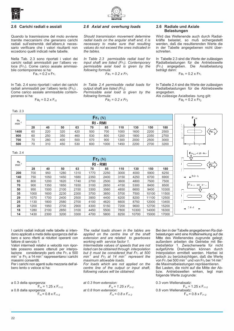
Fr1 (N)
RI - RMI
28 40 50 63 70 85 110 130 150 180
1400 60 220 320 420 500 700 1000 1600 2200 2500
900 60 250 350 460 530 800 1200 1800 2350 2700
700 70 280 400 500 570 900 1300 2000 2500 3000
500 70 310 450 530 600 1000 1450 2200 2700 3200
Tab. 2.4
Tab. 2.3
n2
min-1
Fr2 (N)
RI - RMI
28 40 50 63 70 85 110 130 150 180
200 700 950 1280 1310 1770 2250 3000 4000 5900 6250
140 750 1050 1450 1680 2350 2400 3150 4250 6700 6900
93 800 1200 1620 1740 2700 2500 3600 4800 7500 7500
70 900 1350 1850 1930 3100 2650 4150 5300 8400 8500
50 950 1500 2100 2150 3300 3560 4850 6600 9400 10300
35 1000 1600 2230 2300 3700 3850 5700 7500 10100 11500
29 1070 1700 2400 2500 3900 4400 6200 8200 11100 12500
25 1130 1800 2580 2700 4100 4620 6600 8750 12000 13400
20 1200 1950 2700 2900 4300 5150 7200 9600 12700 15200
18 1280 2100 2850 3100 4450 5500 7800 10300 14000 16300
14 1430 2300 3200 3300 4700 5800 8250 10700 15000 17000
In Table 2.4 permissible radial loads foroutput shaft are listed (Fr2).Permissible axial load is given by thefollowing formula:
Fa2 = 0.2 x Fr2
In Tabelle 2.4 sind die Werte der zulässigenRadialbelastungen für die Abtriebswelleangegeben.Als zulässige Axialbelas- tung gilt:
Fa2 = 0.2 x Fr2
In Tab. 2.4 sono riportati i valori dei carichiradiali ammissibili per l’albero lento (Fr2) .Come carico assiale ammissibile contem-poraneo si ha:
Fa2 = 0.2 x Fr2
The radial loads shown in the tables areapplied on the centre line of the shaftextension and are related to gearboxesworking with service factor 1.Intermediate values of speeds that are notlisted can be obtained through interpolationbut it must be considered that Fr1 at 500min
-1and Fr2 at 14 min
-1represent the
maximum allowable loads.For loads which are not applied on thecentre line of the output or input shaft,following values will be obtained:
at 0.3 from extension:Frx = 1.25 x Fr1-2
at 0.8 from extension:Frx = 0.8 x Fr1-2
Bei den in der Tabelle angegebenen Ra dial-belastungen wird eine Krafteinwirkung auf dieMitte des Wellenendes zugrunde gelegt;außerdem arbeiten die Getriebe mit Be-triebsfaktor 1. Zwischenwerte für nichtaufgeführte Drehzahlen können durchInterpolation ermittelt werden. Hierbei istjedoch zu berücksichtigen, daß die Wertevon Fr1 bei 500 min
-1und von Fr2 bei 14 min
-1
die Maximalbelastungen repräsentieren.Bei Lasten, die nicht auf die Mitte der Ab-bzw. Antriebswellen wirken, legt manfolgende Werte zugrunde:
0.3 vom Wellenabsatz:Frx = 1.25 x Fr1-2
0.8 vom Wellenabsatz:Frx = 0.8 x Fr1-2
Should transmission movement determineradial loads on the angular shaft end, it isnecessary to make sure that resultingvalues do not exceed the ones indicated inthe tables.
In Table 2.3 permissible radial load forinput shaft are listed (Fr1). Contemporarypermissible axial load is given by thefollowing formula:
Fa1 = 0.2 x Fr1
Wird das Wellenende auch durch Radial-kräfte belastet, so muß sichergestelltwerden, daß die resultierenden Werte diein der Tabelle angegebenen nicht über-schreiten.
In Tabelle 2.3 sind die Werte der zulässigenRadialbelastungen für die Antriebswelle(Fr1) angegeben. Die Axialbelastungbeträgt dann:
Fa1 = 0.2 x Fr1
Quando la trasmissione del moto avvienetramite meccanismi che generano carichiradiali sull’estremità dell’albero,è neces-sario verificare che i valori risultanti noneccedono quelli indicati nelle tabelle.
Nella Tab. 2.3 sono riportati i valori deicarichi radiali ammissibili per l’albero ve-loce (Fr1). Come carico assiale ammissi-bile contemporaneo si ha:
Fa1 = 0.2 x Fr1
2.6 Axial and overhung loads2.6 Carichi radiali e assiali 2.6 Radiale und Axiale
Belastungen
I carichi radiali indicati nelle tabelle si inten-dono applicati a metà della sporgenza dell’al-bero e sono riferiti ai riduttori operanti confattore di servizio 1.Valori intermedi relativi a velocità non ripor-tate possono essere ottenuti per interpo-lazione considerando però che Fr1 a 500min
-1e Fr2 a 14 min
-1rappresentano i carichi
massimi consentiti.Per i carichi non agenti sulla mezzeria dell’al-bero lento o veloce si ha:
a 0.3 della sporgenza:Frx = 1.25 x Fr1-2
a 0.8 dalla sporgenza:Frx = 0.8 x Fr1-2
23
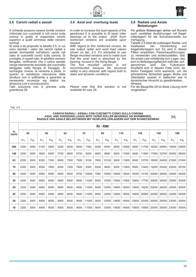
A richiesta possono essere fornite versionirinforzate con cuscinetti a rulli conici sullacorona in grado di sopportare carichisuperiori a quelli ammessi dalle versioninormali.Si veda a tal proposito la tabella 2.5, in cuisono riportati i valori dei carichi radiali eassiali ammissibili sull’albero uscita nelcaso di cuscinetti conici sulla corona. Siconsiglia, in questi casi, di adottare versioniflangiate, verificando che il carico assialevenga interamente assorbito dal cuscinettoalloggiato nella flangia di fissaggio. Sisconsiglia, invece, la versione a piede, inquanto la resistenza meccanica dellastruttura non è sufficiente a garantire lanecessaria sicurezza sia statica siadinamica (urti e sovraccarichi).Tale soluzione non è prevista sullagrandezza 28.
In order to increase the load capacity of thegearboxes it is possible to fit taper rollerbearings on to the output shaft. Suchreinforced versions are available uponrequest.With regard to this reinforced version, letsee output radial and axial load valuesshown on tab. 2.5. It’s advisable to useflange mounted versions and to make surethat the axial load is absorbed by thebearing, housed in the fixing flange.The foot mounted version is notrecommended, because the structuralsafety is very reduced, with regard both tostatic and dynamic conditions.
Please note that this solution is notavailable for size 28.
Für größere Belastungen stehen auf Wunschauch verstärkte Ausführungen mit Kegel-rollenlagern für die Schneckenwelle zurVerfügung.Tabelle 2.5 listet die zulässigen Radial- undAxiallasten bei Verwendung vonKegelrollenlagern auf. Es wird in diesenFällen empfohlen, Flanschausführungenzu verwenden und sicherzustellen, daßdie axiale Last vollständig vom Lager, dassich im Befestigungsflansch befindet, auf-genommen wird. Die Fuâversionempfiehlt sich in diesem Falle nicht, daderen Festigkeit nicht ausreicht, um dieerforderliche Sicherheit gegen Stoße undÜberlasten sowohl in statischer wie indynamischer Hinsicht zu gewährleisten.Hinweis:Für die Baugröße 28 ist diese Lösung nichtvorgesehen.
CARICHI RADIALI - ASSIALI CON CUSCINETTI CONICI SULLA CORONA
AXIAL AND OVERHUNG LOADS WITH TAPER ROLLER BEARINGS ON WORMWHEEL
RADIALE UND AXIALE BELASTUNGEN MIT KEGELROLLENLAGERN AUF DEM SCHNECKENRAD
n2
(rpm)
RI - RMI
40 50 63 70 85 110 130 150 180
Fr2 Fa2 Fr2 Fa2 Fr2 Fa2 Fr2 Fa2 Fr2 Fa2 Fr2 Fa2 Fr2 Fa2 Fr2 Fa2 Fr2 Fa2
200 2300 3000 5100 5900 5200 6000 6000 7300 6000 8000 8500 10900 8300 11700 16000 20800 19000 24800
140 2300 3000 5600 6500 5750 6650 6700 8200 6600 8800 9200 11800 8400 11850 17500 22700 20000 26000
93 2300 3000 6300 7300 6500 7550 7500 9150 7600 10100 9200 11800 9000 12700 18500 24000 21000 27400
70 2300 3000 6550 7600 6200 7200 7600 9300 6500 8650 9200 11800 9500 13400 19200 25000 22000 28700
50 2300 3000 6900 8000 6900 8000 8700 10600 7900 10500 10600 13600 10000 14100 20000 26000 23000 30000
35 2300 3000 6900 8000 6900 8000 9000 11000 9000 12000 13900 17800 12600 17750 20000 26000 23000 30000
29 2300 3000 6900 8000 6900 8000 9000 11000 9000 12000 14800 19000 13600 19200 20000 26000 23000 30000
25 2300 3000 6900 8000 6900 8000 9000 11000 9000 12000 14800 19000 14600 20600 20000 26000 23000 30000
20 2300 3000 6900 8000 6900 8000 9000 11000 9000 12000 14800 19000 15600 22000 20000 26000 23000 30000
18 2300 3000 6900 8000 6900 8000 9000 11000 9000 12000 14800 19000 15600 15600 20000 26000 23000 30000
Tab. 2.5
2.6 Axial and overhung loads2.6 Carichi radiali e assiali 2.6 Radiale und Axiale
Belastungen
[N]
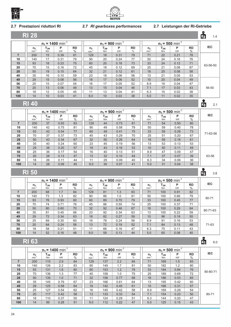
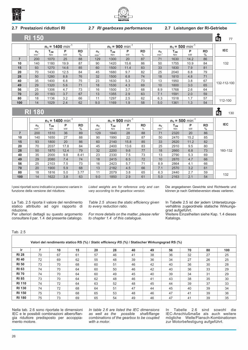
2.7 RI gearboxes performances 2.7 Leistungen der RI-Getriebe2.7 Prestazioni riduttori RI
n1 = 1400 min-1
n1 = 900 min-1
n1 = 500 min-1
IECn2 T2M P RD n2 T2M P RD n2 T2M P RD
min-1
Nm kW % min-1 Nm kW % min
-1Nm kW %
7 200 15 0.39 81 129 18 0.31 79 71 22 0.21 78
63-56-50
10 140 17 0.31 79 90 20 0.24 77 50 24 0.16 76
15 93 18 0.23 75 60 20 0.18 73 33 24 0.12 71
20 70 15 0.16 72 45 18 0.12 69 25 21 0.08 67
28 50 19 0.15 64 32 21 0.12 61 18 25 0.08 58
40 35 16 0.10 59 23 18 0.08 56 13 21 0.05 53
49 29 15 0.08 56 18 17 0.06 52 10 20 0.04 49
56-50
56 25 15 0.07 54 16 17 0.05 52 8.9 19 0.04 47
70 20 13 0.06 49 13 15 0.04 46 7.1 17 0.03 43
80 18 12 0.05 45 11 13 0.04 41 6.3 15 0.02 38
100 14 10 0.03 41 9.0 10 0.03 38 5.0 11 0.02 35
RI 28 1.4
n1 = 1400 min-1
n1 = 900 min-1
n1 = 500 min-1
IECn2 T2M P RD n2 T2M P RD n2 T2M P RD
min-1
Nm kW % min-1 Nm kW % min
-1Nm kW %
7 200 37 0.93 83 129 44 0.73 81 71 54 0.50 80
71-63-56
10 140 42 0.75 81 90 49 0.58 79 50 59 0.40 78
15 93 42 0.54 77 60 49 0.41 75 33 59 0.28 73
20 70 37 0.37 73 45 43 0.29 70 25 51 0.20 67
28 50 43 0.34 67 32 50 0.26 64 18 59 0.18 61
40 35 40 0.24 60 23 45 0.19 56 13 53 0.13 53
49 29 38 0.20 57 18 43 0.16 53 10 50 0.11 49
63-56
56 25 36 0.17 54 16 40 0.13 51 8.9 47 0.09 47
70 20 28 0.13 47 13 32 0.10 44 7.1 37 0.07 39
80 18 26 0.11 44 11 29 0.09 40 6.3 34 0.06 36
100 14 28 0.09 45 9.0 30 0.07 41 5.0 31 0.04 38
RI 40 2.1
n1 = 1400 min-1
n1 = 900 min-1
n1 = 500 min-1
IECn2 T2M P RD n2 T2M P RD n2 T2M P RD
min-1
Nm kW % min-1 Nm kW % min
-1Nm kW %
7 200 68 1.7 84 129 81 1.3 83 71 100 0.91 82
80-7110 140 73 1.3 82 90 86 1.0 81 50 100 0.66 79
15 93 76 0.93 80 60 89 0.70 79 33 100 0.45 77
20 70 74 0.71 76 45 86 0.55 74 25 100 0.37 71
28 50 80 0.60 70 32 92 0.46 67 18 100 0.29 6480-71-63
40 35 81 0.45 66 23 92 0.34 63 13 100 0.22 59
49 29 72 0.34 63 18 82 0.27 59 10 96 0.19 55
71-63
56 25 69 0.30 60 16 78 0.24 56 8.9 91 0.16 53
70 20 64 0.24 56 13 72 0.19 52 7.1 84 0.13 48
80 18 58 0.21 51 11 66 0.16 47 6.3 75 0.11 43
100 14 52 0.16 48 9.0 59 0.13 44 5.0 60 0.08 40
RI 50 3.8
n1 = 1400 min-1
n1 = 900 min-1
n1 = 500 min-1
IECn2 T2M P RD n2 T2M P RD n2 T2M P RD
min-1
Nm kW % min-1 Nm kW % min
-1Nm kW %
7 200 115 2.9 84 129 137 2.2 84 71 169 1.5 83
90-80-71
10 140 126 2.2 83 90 149 1.7 81 50 182 1.2 80
15 93 131 1.6 80 60 153 1.2 78 33 184 0.84 76
20 70 136 1.3 77 45 158 1.0 75 25 189 0.69 72
28 50 135 1.0 71 32 156 0.77 68 18 186 0.53 65
40 35 145 0.79 67 23 166 0.61 64 13 195 0.42 60
49 29 125 0.58 64 18 142 0.45 61 10 166 0.31 57
80-71
56 25 127 0.54 62 16 145 0.42 58 8.9 169 0.29 54
70 20 117 0.42 58 13 133 0.33 54 7.1 154 0.23 50
80 18 110 0.37 55 11 124 0.29 51 6.3 144 0.20 47
100 14 99 0.28 51 9.0 112 0.22 47 5.0 125 0.15 43
RI 63 6.0
24
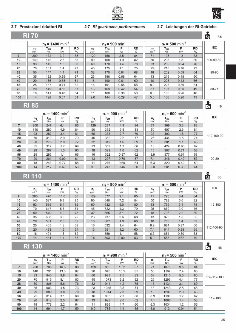
2.7 RI gearboxes performances 2.7 Leistungen der RI-Getriebe2.7 Prestazioni riduttori RI
n1 = 1400 min-1
n1 = 900 min-1
n1 = 500 min-1
IECn2 T2M P RD n2 T2M P RD n2 T2M P RD
min-1
Nm kW % min-1 Nm kW % min
-1Nm kW %
7 200 132 3.2 85 129 158 2.5 84 71 195 1.8 83
100-90-8010 140 142 2.5 83 90 168 1.9 82 50 205 1.3 80
15 93 145 1.8 80 60 170 1.4 78 33 205 0.94 76
20 70 151 1.4 77 45 175 1.1 75 25 210 0.76 72
90-8028 50 147 1.1 71 32 170 0.84 68 18 202 0.59 64
40 35 162 0.89 67 23 186 0.68 64 13 219 0.48 60
49 29 166 0.78 64 18 190 0.61 60 10 223 0.43 56
80-71
56 25 167 0.71 62 16 191 0.55 58 8.9 223 0.39 54
70 20 149 0.55 57 13 169 0.42 54 7.1 197 0.30 49
80 18 141 0.48 54 11 160 0.38 50 6.3 185 0.26 46
100 14 128 0.37 51 9.0 144 0.29 47 5.0 166 0.20 43
RI 70 7.5
n1 = 1400 min-1
n1 = 900 min-1
n1 = 500 min-1
IECn2 T2M P RD n2 T2M P RD n2 T2M P RD
min-1
Nm kW % min-1 Nm kW % min
-1Nm kW %
7 200 247 6.1 85 129 297 4.8 84 71 369 3.3 83
112-100-90
10 140 280 4.9 84 90 332 3.8 83 50 407 2.6 81
15 93 282 3.4 81 60 333 2.7 79 33 403 1.8 77
20 70 310 2.9 79 45 362 2.2 77 25 434 1.5 74
28 50 275 2.0 72 32 319 1.6 69 18 381 1.1 65
40 35 312 1.7 69 23 359 1.3 66 13 424 0.90 62
49 29 287 1.3 65 18 329 1.0 62 10 387 0.71 58
90-80
56 25 283 1.1 66 16 322 0.87 62 8.9 377 0.61 58
70 20 261 0.90 61 13 297 0.70 57 7.1 346 0.49 53
80 18 243 0.77 58 11 276 0.60 54 6.3 320 0.42 50
100 14 217 0.60 53 9.0 243 0.46 50 5.0 281 0.33 44
RI 85 19
n1 = 1400 min-1
n1 = 900 min-1
n1 = 500 min-1
IECn2 T2M P RD n2 T2M P RD n2 T2M P RD
min-1
Nm kW % min-1 Nm kW % min
-1Nm kW %
7 200 478 11.6 86 129 577 9.1 85 71 720 6.4 84
112-100
10 140 537 9.3 85 90 640 7.2 84 50 788 5.0 82
15 93 535 6.4 82 60 632 5.0 80 33 769 3.4 78
20 70 617 5.6 81 45 722 4.3 79 25 869 3.0 76
28 50 570 4.0 75 32 665 3.1 72 18 796 2.2 69
40 35 638 3.3 72 23 737 2.6 68 13 873 1.8 65
112-100-90
49 29 581 2.5 69 18 667 1.9 66 10 786 1.4 62
56 25 465 1.8 69 16 532 1.4 64 8.9 624 0.97 60
70 20 483 1.6 64 13 551 1.2 60 7.1 644 0.88 55
80 18 491 1.5 62 11 559 1.1 58 6.3 651 0.80 53
100 14 444 1.1 57 9.0 503 0.89 53 5.0 583 0.62 49
RI 110 38
n1 = 1400 min-1
n1 = 900 min-1
n1 = 500 min-1
IECn2 T2M P RD n2 T2M P RD n2 T2M P RD
min-1
Nm kW % min-1 Nm kW % min
-1Nm kW %
7 200 706 16.8 88 129 855 13.2 87 71 1070 9.5 84
132-112-100
10 140 791 13.3 87 90 846 10.5 85 50 1167 7.4 83
15 93 840 9.8 84 60 993 7.5 83 33 1210 5.3 80
20 70 915 8.1 83 45 1073 6.2 82 25 1296 4.4 77
28 50 805 5.6 76 32 941 4.2 75 18 1131 3.1 69
40 35 903 4.5 73 23 1045 3.5 71 13 1243 2.5 65
112-100
49 29 880 3.8 70 18 1014 2.8 69 10 1200 2.0 63
56 25 814 3.1 69 16 935 2.3 68 8.9 1100 1.7 62
70 20 812 2.5 67 13 928 2.0 62 7.1 1086 1.4 58
80 18 778 2.2 64 11 886 1.7 60 6.3 1034 1.2 56
100 14 691 1.7 59 9.0 785 1.4 55 5.0 913 0.94 51
RI 130 48
25
2.7 RI gearboxes performances 2.7 Leistungen der RI-Getriebe2.7 Prestazioni riduttori RI
n1 = 1400 min-1
n1 = 900 min-1
n1 = 500 min-1
IECn2 T2M P RD n2 T2M P RD n2 T2M P RD
min-1
Nm kW % min-1 Nm kW % min
-1Nm kW %
7 200 1070 25 88 129 1300 20 87 71 1630 14.2 86
13210 140 1180 19.9 87 90 1420 15.6 86 50 1755 10.9 84
15 93 1270 14.6 85 60 1500 11.4 83 33 1830 7.9 81
20 70 1430 12.5 84 45 1680 9.7 82 25 2040 6.8 79
132-112-100
28 50 1280 8.8 76 32 1500 6.8 74 18 1810 4.8 71
40 35 1400 6.8 75 23 1630 5.3 73 13 1950 3.8 67
49 29 1320 5.6 71 18 1530 4.3 69 10 1800 3.0 65
56 25 1306 4.7 73 16 1500 3.7 68 8.9 1768 2.6 64
70 20 1183 3.7 67 13 1355 2.9 63 7.1 1591 2.0 59
80 18 1136 3.2 66 11 1297 2.5 62 6.3 1518 1.7 57112-100
100 14 1029 2.4 62 9.0 1169 1.9 58 5.0 1361 1.3 54
RI 150 77
n1 = 1400 min-1
n1 = 900 min-1
n1 = 500 min-1
IECn2 T2M P RD n2 T2M P RD n2 T2M P RD
min-1
Nm kW % min-1 Nm kW % min
-1Nm kW %
7 200 1510 36 89 129 1840 28 88 71 2320 20 86
160-132
10 140 1650 27 88 90 1990 22 87 50 2470 15.2 85
15 93 1800 20 86 60 2140 15.8 85 33 2620 11.2 82
20 70 2037 17.8 84 45 2400 13.6 83 25 2910 9.5 80
28 50 1870 12.4 79 32 2200 9.6 77 18 2660 6.8 73
40 35 2000 9.8 8.41 23 2330 7.5 73 13 2790 5.3 69
49 29 2080 7.4 74 18 2415 6.5 72 10 2870 4.7 66
56 25 2103 7.5 73 16 2423 5.7 71 8.9 2864 4.1 66
70 20 1900 5.9 68 13 2182 4.5 66 7.1 2570 3.2 61
80 18 1816 5.0 3.77 11 2079 3.8 65 6.3 2440 2.7 59132
100 14 1622 3.8 63 9.0 1850 2.9 61 5.0 2163 2.1 54
RI 180 130
Listed weights are for reference only and can
vary according to the gearbox version.
Die angegebenen Gewichte sind Richtwerte und
können je nach Getriebeversion etwas variieren.
I pesi riportati sono indicativi e possono variare in
funzione della versione del riduttore.
Valori del rendimento statico RS (%) / Static efficiency RS (%) / Statischer Wirkungsgrad RS (%)
ir 7 10 15 20 28 40 49 56 70 80 100
RI 28 70 67 61 57 46 41 38 36 32 27 25
RI 40 72 69 62 55 48 39 36 34 27 26 25
RI 50 73 70 68 60 51 46 42 40 36 30 28
RI 63 74 70 64 60 50 46 42 40 36 33 29
RI 70 74 70 64 60 49 45 40 39 34 31 29
RI 85 73 70 64 62 48 46 41 43 38 35 30
RI 110 74 72 64 63 52 48 45 44 39 37 33
RI 130 74 72 68 64 51 47 44 45 40 39 34
RI 150 75 73 68 65 53 48 46 47 41 39 36
RI 180 75 73 69 65 54 49 46 47 41 39 35
Tab. 2.5
Table 2.5 shows the static efficiency givento every reduction ratio.
For more details on the matter, please referto chapter 1.4 of this catalogue.
In Tabelle 2.5 ist der jedem Untersetzungs-verhältnis zugeordnete statische Wirkungs-grad aufgeführt.Weitere Einzelheiten siehe Kap. 1.4 diesesKatalogs.
La Tab. 2.5 riporta il valore del rendimentostatico attribuito ad ogni rapporto diriduzione.Per ulteriori dettagli su questo argomentoconsultare il par. 1.4 del presente catalogo.
26
In table 2.6 are listed the IEC dimensionsas well as the possible shaft/flangecombinations of the gearbox to be coupledwith a motor.
In Tabelle 2.6 sind sowohl dieIEC-Anschlußmaße als auch weiteremögliche Welle/Flansch-Kombinationenzur Motorbefestigung aufgeführt.
Nella tab. 2.6 sono riportate le dimensioniIEC e le possibili combinazioni albero/flan-gia riduttore predisposto per accoppia-mento motore.
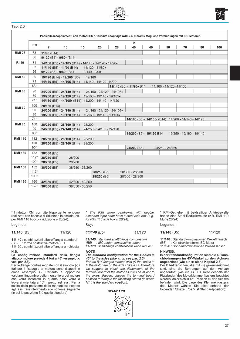
Possibili accoppiamenti con motori IEC / Possible couplings with IEC motors / Mögliche Verbindungen mit IEC-Motoren.
IECir
7 10 15 20 28 40 49 56 70 80 100
RMI 28 63 11/90 (B14)
56 9/120 (B5) - 9/80• (B14)
RI 40 71 14/160 (B5) - 14/105 (B14) - 14/140 - 14/120 - 14/90�
63 11/140 (B5) - 11/90 (B14) 11/120 - 11/80�
56 9/120 (B5) - 9/80• (B14) 9/140 - 9/90
RMI 50 80 19/120 (B14) - 19/200 (B5) 19/160
71 14/160 (B5) - 14/105 (B14) 14/140 - 14/120 -14/90•
63* 11/140 (B5) - 11/90� B14 11/160 - 11/120 -11/105
RMI 63 90 24/200 (B5) - 24/140 (B14) 24/160 - 24/120 - 24/105�
80 19/200 (B5) - 19/120 (B14) 19/160 - 19/140 - 19/105�
71* 14/160 (B5) - 14/105� (B14) 14/200 - 14/140 - 14/120
RMI 70100 28/160 (B14)
90 24/200 (B5) - 24/140 (B14) 24/160 - 24/120 - 24/105�
80 19/200 (B5) - 19/120 (B14) 19/160 - 19/140 - 19/105�
71* 14/160 (B5) - 14/105• (B14) 14/200 - 14/140 - 14/120
RMI 85 100 28/250 (B5) - 28/160 (B14) 28/200
90 24/200 (B5) - 24/140 (B14) 24/250 - 24/160 - 24/120
80* 19/200 (B5) - 19/120 B14 19/250 - 19/160 - 19/140
RMI 110 112 28/250 (B5) - 28/160 (B14) 28/200
100 28/250 (B5) - 28/160 (B14) 28/200
90* 24/200 (B5) 24/250 - 24/160
RMI 130 132 38/300 (B5)
112* 28/250 (B5) 28/200
100* 28/250 (B5) 28/200
RMI 150 132 38/300 (B5) 38/250 - 38/200
112* 28/250 (B5) 28/300 - 28/200
100* 28/250 (B5) 28/300 - 28/200
RMI 180 160 42/350 (B5) 42/300 - 42/250
132* 38/300 (B5) 38/350 - 38/250
Key:
11/140 (B5) 11/120
11/140 : standard shaft/flange combination(B5) : IEC motor constructive shape11/120 : shaft/flange combinations upon request
Tab. 2.6
Legende:
11/140 (B5) 11/120
11/140 : Standardkombinationen Welle/Flansch(B5) : Konstruktionsform IEC-Motor11/120 : Sonderkombinationen Welle/Flansch
Legenda:
11/140 (B5) 11/120
11/140 : combinazioni albero/flangia standard(B5) : forma costruttiva motore IEC11/120 : combinazioni albero/flangia a richiesta
* RMI-Getriebe mit beidseitiger Antriebswellehaben eine Stahl-Reduziermuffe (z.B. RMI 110Muffe 28/24)
* I riduttori RMI con vite bisporgente vengonorealizzati con boccola di riduzione in acciaio (es.per RMI 110 boccola riduzione ø 28/24).
* The RMI worm gearboxes with doubleextended input shaft have a steel axle box (e.g.for RMI 110 axle box ø 28/24).
27
NOTE.
The standard configuration for the 4 holes is
45° to the axles (like an x: see par. 2.3).
For the B14 flanges marked with (•) the holes tofit the motor are on the axles (like a +). Thereforewe suggest to check the dimensions of theterminal board of the motor as it will be at 45° tothe axles. Please, choose the terminal boardposition refering to the following sketch (in whichN° 5 is the standard position):
HINWEIS.
In der Standardkonfiguration sind die 4 Flans-
chbohrungen im 45°-Winkel zu den Achsen
angeordnet (wie ein x: siehe Kapital 2.3).
Bei B14-Flanschen, die mit (•) gekennzeichnetsind, sind die Bohrungen auf den Achsenangeordnet (wie ein +). Es sollte deshalb derPlatzbedarf des Motorklemmenkastens beachtetwerden, da er sich in 45°-Position zu den Achsenbefinden wird. Die Lage des Klemmenkastensdes Motors wählen Sie bitte anhand derfolgenden Skizze (Pos.5 ist Standardposition):
N.B.
La configurazione standard della flangia
attacco motore prevede 4 fori a 45° (esempio x:
vedi par. 2.3).
Per le flange contrassegnate con il simbolo (•) ifori per il fissaggio al motore sono disposti incroce (esempio +). Pertanto è opportunovalutare l’ingombro della morsettiera del motoreche verrà installato in quanto essa verrà atrovarsi orientata a 45° rispetto agli assi. Per lascelta della posizione della morsettiera rispettoagli assi fare riferimento allo schema seguente(in cui la posizione 5 è quella standard):
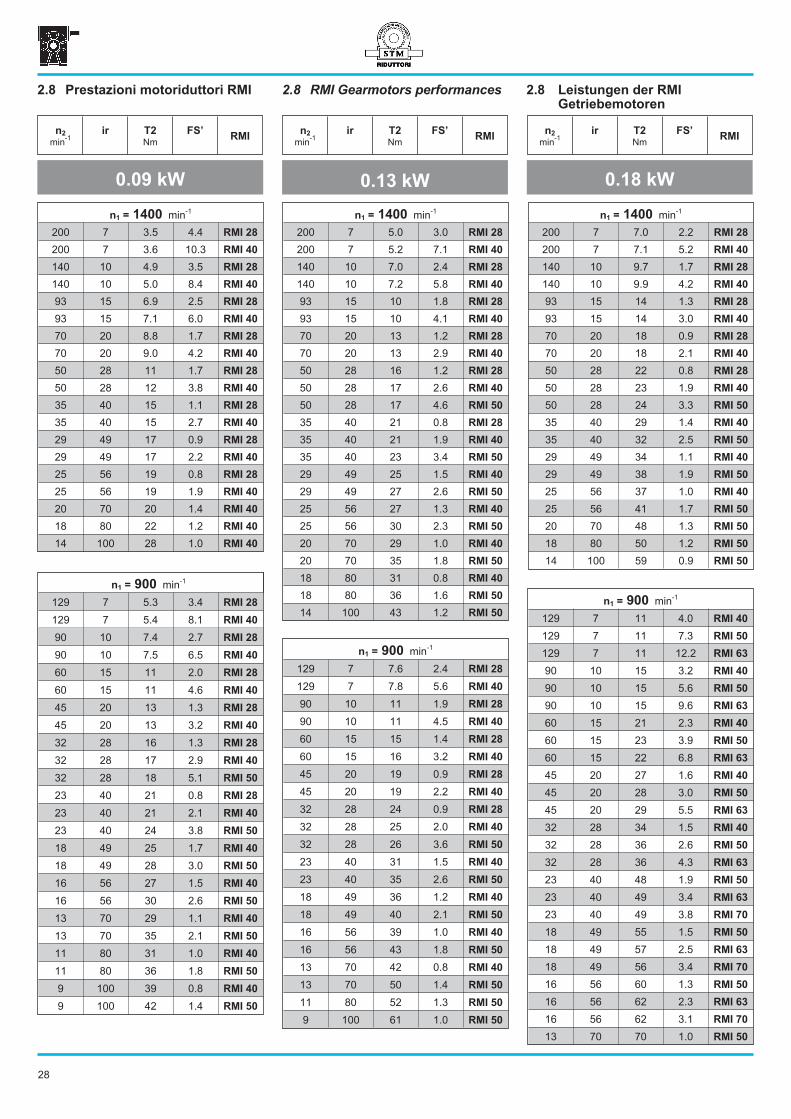
2.8 RMI Gearmotors performances 2.8 Leistungen der RMI
Getriebemotoren
2.8 Prestazioni motoriduttori RMI
0.09 kW 0.13 kW
n2
min-1
ir T2
Nm
FS’RMI
0.18 kW
n2
min-1
ir T2
Nm
FS’RMI
n2
min-1
ir T2
Nm
FS’RMI
n1 = 1400 min-1
200 7 3.5 4.4 RMI 28
200 7 3.6 10.3 RMI 40
140 10 4.9 3.5 RMI 28
140 10 5.0 8.4 RMI 40
93 15 6.9 2.5 RMI 28
93 15 7.1 6.0 RMI 40
70 20 8.8 1.7 RMI 28
70 20 9.0 4.2 RMI 40
50 28 11 1.7 RMI 28
50 28 12 3.8 RMI 40
35 40 15 1.1 RMI 28
35 40 15 2.7 RMI 40
29 49 17 0.9 RMI 28
29 49 17 2.2 RMI 40
25 56 19 0.8 RMI 28
25 56 19 1.9 RMI 40
20 70 20 1.4 RMI 40
18 80 22 1.2 RMI 40
14 100 28 1.0 RMI 40
n1 = 900 min-1
129 7 5.3 3.4 RMI 28
129 7 5.4 8.1 RMI 40
90 10 7.4 2.7 RMI 28
90 10 7.5 6.5 RMI 40
60 15 11 2.0 RMI 28
60 15 11 4.6 RMI 40
45 20 13 1.3 RMI 28
45 20 13 3.2 RMI 40
32 28 16 1.3 RMI 28
32 28 17 2.9 RMI 40
32 28 18 5.1 RMI 50
23 40 21 0.8 RMI 28
23 40 21 2.1 RMI 40
23 40 24 3.8 RMI 50
18 49 25 1.7 RMI 40
18 49 28 3.0 RMI 50
16 56 27 1.5 RMI 40
16 56 30 2.6 RMI 50
13 70 29 1.1 RMI 40
13 70 35 2.1 RMI 50
11 80 31 1.0 RMI 40
11 80 36 1.8 RMI 50
9 100 39 0.8 RMI 40
9 100 42 1.4 RMI 50
n1 = 900 min-1
129 7 7.6 2.4 RMI 28
129 7 7.8 5.6 RMI 40
90 10 11 1.9 RMI 28
90 10 11 4.5 RMI 40
60 15 15 1.4 RMI 28
60 15 16 3.2 RMI 40
45 20 19 0.9 RMI 28
45 20 19 2.2 RMI 40
32 28 24 0.9 RMI 28
32 28 25 2.0 RMI 40
32 28 26 3.6 RMI 50
23 40 31 1.5 RMI 40
23 40 35 2.6 RMI 50
18 49 36 1.2 RMI 40
18 49 40 2.1 RMI 50
16 56 39 1.0 RMI 40
16 56 43 1.8 RMI 50
13 70 42 0.8 RMI 40
13 70 50 1.4 RMI 50
11 80 52 1.3 RMI 50
9 100 61 1.0 RMI 50
28
n1 = 1400 min-1
200 7 5.0 3.0 RMI 28
200 7 5.2 7.1 RMI 40
140 10 7.0 2.4 RMI 28
140 10 7.2 5.8 RMI 40
93 15 10 1.8 RMI 28
93 15 10 4.1 RMI 40
70 20 13 1.2 RMI 28
70 20 13 2.9 RMI 40
50 28 16 1.2 RMI 28
50 28 17 2.6 RMI 40
50 28 17 4.6 RMI 50
35 40 21 0.8 RMI 28
35 40 21 1.9 RMI 40
35 40 23 3.4 RMI 50
29 49 25 1.5 RMI 40
29 49 27 2.6 RMI 50
25 56 27 1.3 RMI 40
25 56 30 2.3 RMI 50
20 70 29 1.0 RMI 40
20 70 35 1.8 RMI 50
18 80 31 0.8 RMI 40
18 80 36 1.6 RMI 50
14 100 43 1.2 RMI 50
n1 = 1400 min-1
200 7 7.0 2.2 RMI 28
200 7 7.1 5.2 RMI 40
140 10 9.7 1.7 RMI 28
140 10 9.9 4.2 RMI 40
93 15 14 1.3 RMI 28
93 15 14 3.0 RMI 40
70 20 18 0.9 RMI 28
70 20 18 2.1 RMI 40
50 28 22 0.8 RMI 28
50 28 23 1.9 RMI 40
50 28 24 3.3 RMI 50
35 40 29 1.4 RMI 40
35 40 32 2.5 RMI 50
29 49 34 1.1 RMI 40
29 49 38 1.9 RMI 50
25 56 37 1.0 RMI 40
25 56 41 1.7 RMI 50
20 70 48 1.3 RMI 50
18 80 50 1.2 RMI 50
14 100 59 0.9 RMI 50
n1 = 900 min-1
129 7 11 4.0 RMI 40
129 7 11 7.3 RMI 50
129 7 11 12.2 RMI 63
90 10 15 3.2 RMI 40
90 10 15 5.6 RMI 50
90 10 15 9.6 RMI 63
60 15 21 2.3 RMI 40
60 15 23 3.9 RMI 50
60 15 22 6.8 RMI 63
45 20 27 1.6 RMI 40
45 20 28 3.0 RMI 50
45 20 29 5.5 RMI 63
32 28 34 1.5 RMI 40
32 28 36 2.6 RMI 50
32 28 36 4.3 RMI 63
23 40 48 1.9 RMI 50
23 40 49 3.4 RMI 63
23 40 49 3.8 RMI 70
18 49 55 1.5 RMI 50
18 49 57 2.5 RMI 63
18 49 56 3.4 RMI 70
16 56 60 1.3 RMI 50
16 56 62 2.3 RMI 63
16 56 62 3.1 RMI 70
13 70 70 1.0 RMI 50
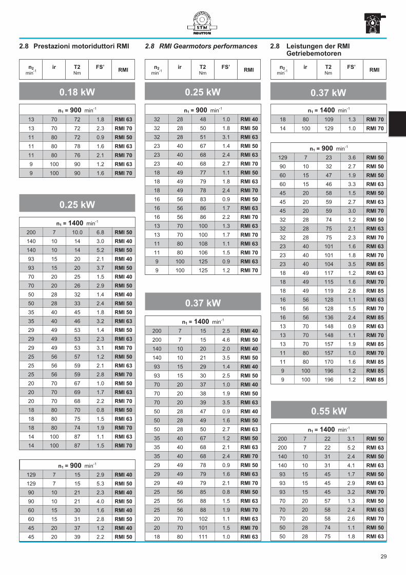
2.8 RMI Gearmotors performances 2.8 Leistungen der RMI
Getriebemotoren
2.8 Prestazioni motoriduttori RMI
n2
min-1
ir T2
Nm
FS’RMI
n2
min-1
ir T2
Nm
FS’RMI
n2
min-1
ir T2
Nm
FS’RMI
0.18 kW 0.25 kW 0.37 kW
n1 = 900 min-1
13 70 72 1.8 RMI 63
13 70 72 2.3 RMI 70
11 80 72 0.9 RMI 50
11 80 78 1.6 RMI 63
11 80 76 2.1 RMI 70
9 100 90 1.2 RMI 63
9 100 90 1.6 RMI 70
0.55 kW
n1 = 1400 min-1
200 7 10.0 6.8 RMI 50
140 10 14 3.0 RMI 40
140 10 14 5.2 RMI 50
93 15 20 2.1 RMI 40
93 15 20 3.7 RMI 50
70 20 25 1.5 RMI 40
70 20 26 2.9 RMI 50
50 28 32 1.4 RMI 40
50 28 33 2.4 RMI 50
35 40 45 1.8 RMI 50
35 40 46 3.2 RMI 63
29 49 53 1.4 RMI 50
29 49 53 2.3 RMI 63
29 49 53 3.1 RMI 70
25 56 57 1.2 RMI 50
25 56 59 2.1 RMI 63
25 56 59 2.8 RMI 70
20 70 67 1.0 RMI 50
20 70 69 1.7 RMI 63
20 70 68 2.2 RMI 70
18 80 70 0.8 RMI 50
18 80 75 1.5 RMI 63
18 80 74 1.9 RMI 70
14 100 87 1.1 RMI 63
14 100 87 1.5 RMI 70
n1 = 900 min-1
129 7 15 2.9 RMI 40
129 7 15 5.3 RMI 50
90 10 21 2.3 RMI 40
90 10 21 4.0 RMI 50
60 15 30 1.6 RMI 40
60 15 31 2.8 RMI 50
45 20 37 1.2 RMI 40
45 20 39 2.2 RMI 50
0.25 kW
n1 = 1400 min-1
200 7 15 2.5 RMI 40
200 7 15 4.6 RMI 50
140 10 20 2.0 RMI 40
140 10 21 3.5 RMI 50
93 15 29 1.4 RMI 40
93 15 30 2.5 RMI 50
70 20 37 1.0 RMI 40
70 20 38 1.9 RMI 50
70 20 39 3.5 RMI 63
50 28 47 0.9 RMI 40
50 28 49 1.6 RMI 50
50 28 50 2.7 RMI 63
35 40 67 1.2 RMI 50
35 40 68 2.1 RMI 63
35 40 68 2.4 RMI 70
29 49 78 0.9 RMI 50
29 49 79 1.6 RMI 63
29 49 79 2.1 RMI 70
25 56 85 0.8 RMI 50
25 56 88 1.5 RMI 63
25 56 88 1.9 RMI 70
20 70 102 1.1 RMI 63
20 70 101 1.5 RMI 70
18 80 111 1.0 RMI 63
n1 = 1400 min-1
18 80 109 1.3 RMI 70
14 100 129 1.0 RMI 70
n1 = 900 min-1
129 7 23 3.6 RMI 50
90 10 32 2.7 RMI 50
60 15 47 1.9 RMI 50
60 15 46 3.3 RMI 63
45 20 58 1.5 RMI 50
45 20 59 2.7 RMI 63
45 20 59 3.0 RMI 70
32 28 74 1.2 RMI 50
32 28 75 2.1 RMI 63
32 28 75 2.3 RMI 70
23 40 101 1.6 RMI 63
23 40 101 1.8 RMI 70
23 40 104 3.5 RMI 85
18 49 117 1.2 RMI 63
18 49 115 1.6 RMI 70
18 49 119 2.8 RMI 85
16 56 128 1.1 RMI 63
16 56 128 1.5 RMI 70
16 56 136 2.4 RMI 85
13 70 148 0.9 RMI 63
13 70 148 1.1 RMI 70
13 70 157 1.9 RMI 85
11 80 157 1.0 RMI 70
11 80 170 1.6 RMI 85
9 100 196 1.2 RMI 85
9 100 196 1.2 RMI 85
29
n1 = 900 min-1
32 28 48 1.0 RMI 40
32 28 50 1.8 RMI 50
32 28 51 3.1 RMI 63
23 40 67 1.4 RMI 50
23 40 68 2.4 RMI 63
23 40 68 2.7 RMI 70
18 49 77 1.1 RMI 50
18 49 79 1.8 RMI 63
18 49 78 2.4 RMI 70
16 56 83 0.9 RMI 50
16 56 86 1.7 RMI 63
16 56 86 2.2 RMI 70
13 70 100 1.3 RMI 63
13 70 100 1.7 RMI 70
11 80 108 1.1 RMI 63
11 80 106 1.5 RMI 70
9 100 125 0.9 RMI 63
9 100 125 1.2 RMI 70
n1 = 1400 min-1
200 7 22 3.1 RMI 50
200 7 22 5.2 RMI 63
140 10 31 2.4 RMI 50
140 10 31 4.1 RMI 63
93 15 45 1.7 RMI 50
93 15 45 2.9 RMI 63
93 15 45 3.2 RMI 70
70 20 57 1.3 RMI 50
70 20 58 2.4 RMI 63
70 20 58 2.6 RMI 70
50 28 74 1.1 RMI 50
50 28 75 1.8 RMI 63
0.37 kW
0.55 kW 0.75 kW
n2
min-1
ir T2
Nm
FS’RMI
n2
min-1
ir T2
Nm
FS’RMI
n2
min-1
ir T2
Nm
FS’RMI
n1 = 900 min-1
129 7 34 2.4 RMI 50
90 10 47 1.8 RMI 50
90 10 47 3.2 RMI 63
60 15 69 1.3 RMI 50
60 15 68 2.2 RMI 63
60 15 68 2.5 RMI 70
45 20 86 1.0 RMI 50
45 20 88 1.8 RMI 63
45 20 88 2.0 RMI 70
32 28 109 0.8 RMI 50
32 28 111 1.4 RMI 63
32 28 111 1.5 RMI 70
23 40 149 1.1 RMI 63
23 40 149 1.2 RMI 70
23 40 154 2.3 RMI 85
18 49 174 0.8 RMI 63
18 49 172 1.1 RMI 70
18 49 177 1.9 RMI 85
16 56 190 0.8 RMI 63
16 56 190 1.0 RMI 70
16 56 203 1.6 RMI 85
13 70 221 0.8 RMI 70
13 70 233 1.3 RMI 85
11 80 252 1.1 RMI 85
9 100 292 0.8 RMI 85
2.8 RMI Gearmotors performances 2.8 Leistungen der RMI
Getriebemotoren
2.8 Prestazioni motoriduttori RMI
1.1 kW
n1 = 1400 min-1
200 7 30 2.3 RMI 50
200 7 30 3.8 RMI 63
140 10 42 1.7 RMI 50
140 10 42 3.0 RMI 63
93 15 61 1.2 RMI 50
93 15 61 2.1 RMI 63
93 15 61 2.4 RMI 70
70 20 78 1.0 RMI 50
70 20 79 1.7 RMI 63
70 20 79 1.9 RMI 70
50 28 100 0.8 RMI 50
50 28 102 1.3 RMI 63
50 28 102 1.4 RMI 70
35 40 137 1.1 RMI 63
35 40 137 1.2 RMI 70
35 40 141 2.2 RMI 85
29 49 160 1.0 RMI 70
29 49 163 1.8 RMI 85
25 56 178 0.9 RMI 70
25 56 189 1.5 RMI 85
20 70 218 1.2 RMI 85
18 80 237 1.0 RMI 85
14 100 271 0.8 RMI 85
n1 = 900 min-1
129 7 47 2.9 RMI 63
90 10 64 2.3 RMI 63
90 10 65 2.6 RMI 70
60 15 93 1.6 RMI 63
60 15 93 1.8 RMI 70
45 20 119 1.3 RMI 63
45 20 119 1.5 RMI 70
45 20 123 3.0 RMI 85
32 28 152 1.0 RMI 63
32 28 152 1.1 RMI 70
32 28 154 2.1 RMI 85
23 40 210 1.7 RMI 85
23 40 216 3.4 RMI 110
18 49 242 1.4 RMI 85
18 49 257 2.6 RMI 110
16 56 276 1.2 RMI 85
16 56 285 1.9 RMI 110
13 70 318 0.9 RMI 85
13 70 334 1.6 RMI 110
11 80 344 0.8 RMI 85
11 80 369 1.5 RMI 110
9 100 422 1.2 RMI 110
n1 = 1400 min-1
200 7 44 2.6 RMI 63
200 7 45 2.9 RMI 70
140 10 62 2.0 RMI 63
140 10 62 2.3 RMI 70
93 15 90 1.4 RMI 63
93 15 90 1.6 RMI 70
93 15 91 3.1 RMI 85
70 20 116 1.2 RMI 63
70 20 116 1.3 RMI 70
70 20 119 2.6 RMI 85
50 28 149 0.9 RMI 63
50 28 149 1.0 RMI 70
50 28 151 1.8 RMI 85
35 40 207 1.5 RMI 85
35 40 216 3.0 RMI 110
29 49 239 1.2 RMI 85
29 49 254 2.3 RMI 110
25 56 277 1.0 RMI 85
25 56 290 1.6 RMI 110
20 70 320 0.8 RMI 85
20 70 336 1.4 RMI 110
18 80 372 1.3 RMI 110
14 100 428 1.0 RMI 110
n1 = 1400 min-1
50 28 75 2.0 RMI 70
35 40 101 1.4 RMI 63
35 40 101 1.6 RMI 70
35 40 104 3.0 RMI 85
29 49 118 1.1 RMI 63
29 49 118 1.4 RMI 70
29 49 119 2.4 RMI 85
25 56 130 1.0 RMI 63
25 56 130 1.3 RMI 70
25 56 139 2.0 RMI 85
20 70 150 1.0 RMI 70
20 70 160 1.6 RMI 85
18 80 162 0.9 RMI 70
18 80 174 1.4 RMI 85
14 100 199 1.1 RMI 85
n1 = 900 min-1
129 7 69 2.0 RMI 63
129 7 69 2.3 RMI 70
90 10 95 1.6 RMI 63
90 10 96 1.8 RMI 70
60 15 137 1.1 RMI 63
60 15 137 1.2 RMI 70
60 15 138 2.4 RMI 85
45 20 175 0.9 RMI 63
45 20 175 1.0 RMI 70
45 20 180 2.0 RMI 85
32 28 226 1.4 RMI 85
23 40 308 1.2 RMI 85
23 40 317 2.3 RMI 110
18 49 355 0.9 RMI 85
18 49 377 1.8 RMI 110
16 56 418 1.3 RMI 110
13 70 490 1.1 RMI 110
11 80 542 1.0 RMI 110
9 100 619 0.8 RMI 110
30
1.5 kW 1.8 kW
n2
min-1
ir T2
Nm
FS’RMI
2.2 kW
n2
min-1
ir T2
Nm
FS’RMI
n2
min-1
ir T2
Nm
FS’RMI
n1 = 1400 min-1
200 7 60 1.9 RMI 63
200 7 61 2.2 RMI 70
140 10 85 1.5 RMI 63
140 10 85 1.7 RMI 70
140 10 86 3.3 RMI 85
93 15 123 1.1 RMI 63
93 15 123 1.2 RMI 70
93 15 124 2.3 RMI 85
70 20 158 0.9 RMI 63
70 20 158 1.0 RMI 70
70 20 162 1.9 RMI 85
50 28 206 1.3 RMI 85
35 40 282 1.1 RMI 85
35 40 295 2.2 RMI 110
29 49 326 0.9 RMI 85
29 49 346 1.7 RMI 110
25 56 395 1.2 RMI 110
20 70 458 1.1 RMI 110
18 80 508 1.0 RMI 110
n1 = 900 min-1
129 7 94 3.2 RMI 85
90 10 132 2.5 RMI 85
60 15 189 1.8 RMI 85
60 15 191 3.3 RMI 110
45 20 245 1.5 RMI 85
45 20 251 2.9 RMI 110
32 28 308 1.0 RMI 85
32 28 321 2.1 RMI 110
32 28 334 2.8 RMI 130
23 40 433 1.7 RMI 110
23 40 452 2.3 RMI 130
18 49 515 1.3 RMI 110
18 49 538 1.9 RMI 130
18 49 538 2.8 RMI 150
16 56 570 0.9 RMI 110
16 56 606 1.5 RMI 130
16 56 606 2.5 RMI 150
13 70 691 1.3 RMI 130
13 70 702 1.9 RMI 150
11 80 764 1.2 RMI 130
11 80 789 1.6 RMI 150
9 100 875 0.9 RMI 130
9 100 923 1.3 RMI 150
2.8 RMI Gearmotors performances 2.8 Leistungen der RMI
Getriebemotoren
2.8 Prestazioni motoriduttori RMI
n1 = 1400 min-1
200 7 74 1.5 RMI 63
200 7 75 1.8 RMI 70
200 7 75 3.3 RMI 85
140 10 105 1.2 RMI 63
140 10 105 1.4 RMI 70
140 10 106 2.6 RMI 85
93 15 151 0.9 RMI 63
93 15 151 1.0 RMI 70
93 15 153 1.8 RMI 85
70 20 194 0.8 RMI 70*
70 20 199 1.6 RMI 85
50 28 254 1.1 RMI 85
35 40 348 0.9 RMI 85*
35 40 363 1.8 RMI 110
29 49 427 1.4 RMI 110
25 56 488 1.0 RMI 110
20 70 565 0.9 RMI 110
n1 = 900 min-1
129 7 115 2.6 RMI 85
90 10 163 2.0 RMI 85
60 15 233 1.4 RMI 85
60 15 236 2.7 RMI 110
45 20 302 1.2 RMI 85
45 20 310 2.3 RMI 110
45 20 322 3.3 RMI 130
32 28 379 0.8 RMI 85*
32 28 396 1.7 RMI 110
32 28 412 2.3 RMI 130
23 40 534 1.4 RMI 110
23 40 558 1.9 RMI 130
23 40 573 2.8 RMI 150
18 49 635 1.1 RMI 110
18 49 664 1.5 RMI 130
18 49 664 2.3 RMI 150
16 56 748 1.3 RMI 130
16 56 748 2.0 RMI 150
13 70 852 1.1 RMI 130
13 70 866 1.6 RMI 150
11 80 942 0.9 RMI 130
11 80 974 1.3 RMI 150
9 100 1139 1.0 RMI 150
n1 = 1400 min-1
200 7 89 1.5 RMI 70
200 7 89 2.8 RMI 85
140 10 125 1.1 RMI 70
140 10 126 2.2 RMI 85
93 15 180 0.8 RMI 70*
93 15 182 1.6 RMI 85
70 20 237 1.3 RMI 85
70 20 243 2.5 RMI 110
70 20 249 3.7 RMI 130
50 28 303 0.9 RMI 85*
50 28 315 1.8 RMI 110
50 28 319 2.5 RMI 130
35 40 432 1.5 RMI 110
35 40 438 2.1 RMI 130
35 40 450 3.1 RMI 150
29 49 507 1.1 RMI 110
29 49 515 1.7 RMI 130
29 49 522 2.5 RMI 150
25 56 580 0.8 RMI 110
25 56 580 1.4 RMI 130
25 56 613 2.1 RMI 150
20 70 704 1.2 RMI 130
20 70 704 1.7 RMI 150
18 80 768 1.0 RMI 130
18 80 792 1.4 RMI 150
14 100 930 1.1 RMI 150
n1 = 900 min-1
129 7 137 2.2 RMI 85
129 7 139 4.2 RMI 110
90 10 194 1.7 RMI 85
90 10 196 3.3 RMI 110
60 15 277 1.2 RMI 85
60 15 280 2.3 RMI 110
60 15 291 3.4 RMI 130
45 20 360 1.0 RMI 85
45 20 369 2.0 RMI 110
45 20 383 2.8 RMI 130
32 28 471 1.4 RMI 110
32 28 490 1.9 RMI 130
32 28 484 3.1 RMI 150
23 40 635 1.2 RMI 110
23 40 663 1.6 RMI 130
23 40 682 2.4 RMI 150
18 49 755 0.9 RMI 110
18 49 789 1.3 RMI 130
31
2.2kW 3 kW
n2
min-1
ir T2
Nm
FS’RMI
4 kW
n2
min-1
ir T2
Nm
FS’RMI
n2
min-1
ir T2
Nm
FS’RMI
n1 = 1400 min-1
200 7 122 1.2 RMI 70*
200 7 122 2.0 RMI 85
140 10 170 0.8 RMI 70*
140 10 172 1.6 RMI 85
93 15 249 1.1 RMI 85 *
93 15 252 2.1 RMI 110
93 15 258 3.3 RMI 130
70 20 323 1.0 RMI 85*
70 20 332 1.9 RMI 110
70 20 340 2.7 RMI 130
50 28 430 1.3 RMI 110
50 28 435 1.8 RMI 130
50 28 435 2.9 RMI 150
35 40 589 1.1 RMI 110
35 40 598 1.5 RMI 130
35 40 614 2.3 RMI 150
29 49 692 0.8 RMI 110*
29 49 702 1.3 RMI 130
29 49 712 1.9 RMI 150
25 56 791 1.0 RMI 130
25 56 837 1.6 RMI 150
20 70 960 0.8 RMI 130
20 70 960 1.2 RMI 150
18 80 1081 1.1 RMI 150
14 100 1269 0.8 RMI 150
2.8 RMI Gearmotors performances 2.8 Leistungen der RMI
Getriebemotoren
2.8 Prestazioni motoriduttori RMI
n1 = 900 min-1
129 7 194 4.4 RMI 130
129 7 194 6.7 RMI 150
90 10 271 3.5 RMI 130
90 10 274 5.2 RMI 150
60 15 396 2.5 RMI 130
60 15 396 3.8 RMI 150
n1 = 1400 min-1
200 7 162 1.5 RMI 85*
200 7 164 2.9 RMI 110
140 10 229 1.2 RMI 85*
140 10 232 2.3 RMI 110
140 10 237 3.3 RMI 130
93 15 332 0.9 RMI 85*
93 15 336 1.6 RMI 110
93 15 344 2.4 RMI 130
70 20 442 1.4 RMI 110
70 20 453 2.0 RMI 130
70 20 458 3.1 RMI 150
50 28 573 1.0 RMI 110*
50 28 581 1.4 RMI 130
50 28 581 2.2 RMI 150
35 40 786 0.8 RMI 110*
35 40 797 1.1 RMI 130
35 40 819 1.7 RMI 150
29 49 936 0.9 RMI 130*
29 49 949 1.4 RMI 150
25 56 1115 1.2 RMI 150
20 70 1280 0.9 RMI 150
18 80 1441 0.8 RMI 150
n1 = 900 min-1
129 7 258 3.3 RMI 130
129 7 258 5.0 RMI 150
90 10 361 2.6 RMI 130
90 10 365 3.9 RMI 150
60 15 528 1.9 RMI 130
60 15 528 2.8 RMI 150
45 20 696 1.5 RMI 130
45 20 696 2.4 RMI 150
45 20 705 3.4 RMI 180
32 28 891 1.1 RMI 130
32 28 879 1.7 RMI 150
32 28 915 2.4 RMI 180
23 40 1239 1.3 RMI 150
23 40 1239 1.9 RMI 180
18 49 1435 1.1 RMI 150
18 49 1497 1.6 RMI 180
16 56 1616 0.9 RMI 150
16 56 1688 1.4 RMI 180
13 70 1961 1.1 RMI 180
11 80 2207 0.9 RMI 180
n1 = 900 min-1
18 49 789 1.9 RMI 150
16 56 889 1.1 RMI 130
16 56 889 1.7 RMI 150
13 70 1013 0.9 RMI 130
13 70 1029 1.3 RMI 150
11 80 1121 0.8 RMI 130
11 80 1158 1.1 RMI 150
9 100 1354 0.9 RMI 150
3 kW
n1 = 900 min-1
45 20 522 2.1 RMI 130
45 20 522 3.2 RMI 150
32 28 669 1.4 RMI 130
32 28 660 2.3 RMI 150
32 28 686 3.2 RMI 180
23 40 930 1.8 RMI 150
23 40 930 2.5 RMI 180
18 49 1076 1.4 RMI 150
18 49 1123 2.2 RMI 180
16 56 1212 1.2 RMI 150
16 56 1266 1.9 RMI 180
13 70 1404 1.0 RMI 150
13 70 1471 1.5 RMI 180
11 80 1655 1.3 RMI 180
9 100 1942 1.0 RMI 180
5.5 kW
n1 = 1400 min-1
200 7 231 3.1 RMI 130
200 7 231 4.6 RM I150
140 10 326 2.4 RMI 130
140 10 326 3.6 RMI 150
93 15 473 1.8 RMI 130
93 15 478 2.7 RMI 150
70 20 623 1.5 RMI 130
70 20 630 2.3 RMI 150
70 20 630 3.2 RMI 180
50 28 798 1.0 RMI 130*
50 28 798 1.6 RMI 150
50 28 830 2.3 RMI 180
35 40 1126 1.2 RMI 150
35 40 1126 1.8 RMI 180
29 49 1305 1.0 RMI 150
29 49 1360 1.5 RMI 180
25 56 1534 0.9 RMI 150
25 56 1534 1.4 RMI 180
20 70 1786 1.1 RMI 180
18 80 2011 0.9 RMI 180
4 kW
32
5.5 kW 7.5 kW
n2
min-1
ir T2
Nm
FS’RMI
15 kW
n2
min-1
ir T2
Nm
FS’RMI
n2
min-1
ir T2
Nm
FS’RMI
n1 = 900 min-1
129 7 355 2.4 RMI 130
129 7 355 3.7 RMI 150
90 10 496 1.9 RMI 130
90 10 502 2.8 RMI 150
60 15 727 1.4 RMI 130
60 15 727 2.1 RMI 150
60 15 744 2.9 RMI 180
45 20 957 1.1 RMI 130
45 20 957 1.8 RMI 150
45 20 969 2.5 RMI 180
32 28 1226 0.8 RMI 130*
32 28 1209 1.2 RMI 150
32 28 1258 1.7 RMI 180
23 40 1704 1.0 RMI 150
23 40 1704 1.4 RMI 180
18 49 2059 1.2 RMI 180
16 56 2320 1.0 RMI 180
13 70 2696 0.8 RMI 180
n1 = 1400 min-1
200 7 315 2.2 RMI 130
200 7 315 3.4 RMI 150
140 10 445 1.8 RMI 130
140 10 445 2.7 RMI 150
140 10 450 3.7 RMI 180
93 15 645 1.3 RMI 130*
93 15 652 1.9 RMI 150
93 15 660 2.7 RMI 180
70 20 849 1.1 RMI 130*
70 20 860 1.7 RMI 150
70 20 860 2.4 RMI 180
50 28 1089 1.2 RMI 150*
50 28 1132 1.7 RMI 180
35 40 1535 0.9 RMI 150*
35 40 1535 1.3 RMI 180
29 49 1855 1.1 RMI 180
25 56 2091 1.0 RMI 180
2.8 RMI Gearmotors performances 2.8 Leistungen der RMI
Getriebemotoren
2.8 Prestazioni motoriduttori RMI
n1 = 900 min-1
129 7 490 3.8 RMI 180
90 10 692 2.9 RMI 180
60 15 1015 2.1 RMI 180
45 20 1321 1.8 RMI 180
n1 = 1400 min-1
200 7 387 1.8 RMI 130
200 7 387 2.8 RMI 150
200 7 391 3.9 RMI 180
140 10 546 1.4 RMI 130*
140 10 546 2.2 RMI 150
140 10 552 3.0 RMI 180
93 15 791 1.1 RMI 130*
93 15 800 1.6 RMI 150
93 15 810 2.2 RMI 180
70 20 1042 0.9 RMI 130*
70 20 1054 1.4 RMI 150
70 20 1054 1.9 RMI 180
50 28 1335 1.0 RMI 150*
50 28 1388 1.3 RMI 180
35 40 1883 1.1 RMI 180*
29 49 2276 0.9 RMI 180*
25 56 2566 0.8 RMI 180*
n1 = 1400 min-1
200 7 467 3.2 RMI 180
140 10 660 2.5 RMI 180
93 15 968 1.9 RMI 180
70 20 1261 1.6 RMI 180
50 28 1660 1.1 RMI 180*
35 40 2251 0.9 RMI 180*
29 49 2721 0.8 RMI 180*
11 kW
n1 = 900 min-1
129 7 719 2.6 RMI 180
90 10 1015 2.0 RMI 180
60 15 1488 1.4 RMI 180
45 20 1938 1.2 RMI 180
32 28 2517 0.9 RMI 180*
n1 = 1400 min-1
200 7 637 2.4 RMI 180
140 10 900 1.8 RMI 180
93 15 1320 1.4 RMI 180
70 20 1719 1.2 RMI 180*
50 28 2263 0.8 RMI 180*
7.5 kW
N.B.Tutte le potenze indicate si riferiscono allapotenza meccanica dei riduttori.Per i riduttori contrassegnati con (*) èopportuno effettuare la verifica dellapotenza limite termico secondo leindicazioni riportate nel par. 1.7NOTE.The indicated power is based on themechanical capacities of the gearboxes.For the gearboxes marked with (*) it is aslonecessary to obey the therminal capacitylike shown on chapter 1.7.HINWEIS.Die Leistungsangaben beziehen sich aufdie mecanische Belasbarkeit der Getriebe.Bei den mit (*) gekennzeichnetenGetrieben ist außerdem die thermischeLeistungsgrenze zu beachten (s. Kap. 1.7).
9.2 kW
n1 = 900 min-1
32 28 1716 1.3 RMI 180
23 40 2324 1.0 RMI 180
18 49 2808 0.9 RMI 180
33
34
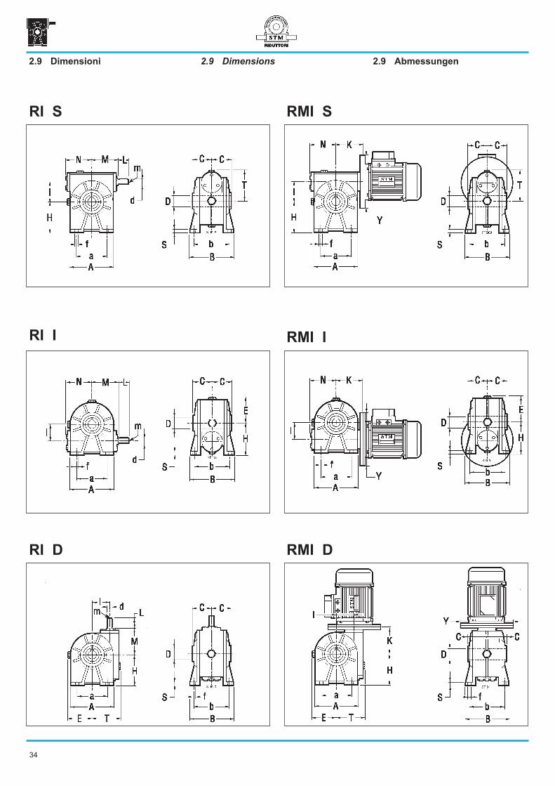
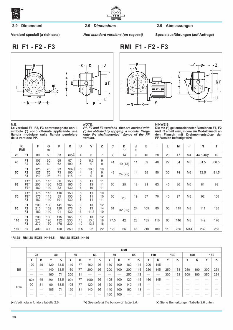
2.9 Dimensions2.9 Dimensioni 2.9 Abmessungen
RI I
RMI D
RMI S
RMI I
RI D
RI S
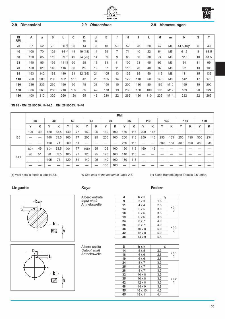
35
+2- 8
�3
RI
RMI
A a B b C D
H7
d
j6
E f H I L M m N S T
28 67 52 78 66 30 14 9 40 5.5 52 28 20 47 M4 44.5(46)* 6 49
40 100 70 102 84 41 19 (18) 11 59 7 71 40 22 64 M5 61.5 8 68.5
50 120 85 119 99 49 24 (25) 14 69 9 85 50 30 74 M6 72.5 10 81.5
63 140 95 136 111 60 25 18 81 11 100 63 45 96 M6 84 11 99
70 158 120 140 116 60 28 19 87 11 115 70 40 97 M8 92 13 108
85 193 140 168 140 61 32 (35) 24 105 13 135 85 50 115 M8 111 15 135
110 250 200 200 162 77.5 42 28 135 14 172 110 60 146 M8 142 17 170
130 286 235 230 190 90 48 38 150 15 200 130 80 166 M10 159 19 200
150 336 260 250 210 105 55 42 178 19 230 150 100 195 M12 189 20 224
180 400 310 320 260 120 65 48 210 22 265 180 110 235 M14 232 22 265
�3
2.9 Dimensions
Keys
2.9 Abmessungen2.9 Dimensioni
FedernLinguette
D b x h t2
14 5 x 5 2.3+ 0.1
018 6 x 6 2.8
19 6 x 6 2.8
24 8 x 7 3.3
25 8 x 7 3.3
+ 0.2
0
28 8 x 7 3.3
32 10 x 8 3.3
35 10 x 8 3.3
42 12 x 8 3.3
48 14 x 9 3.8
55 16 x 10 4.3
65 18 x 11 4.4
d b x h t1
9 3 x 3 1.8
+ 0.1
0
11 4 x 4 2.5
14 5 x 5 3.0
18 6 x 6 3.5
19 6 x 6 3.5
24 8 x 7 4.0
+ 0.2
0
28 8 x 7 4.0
38 10 x 8 5.0
42 12 x 8 5.0
48 14 x 9 5.5
Albero uscitaOutput shaftAbtriebswelle
Albero entrataInput shaftAntriebswelle
RMI
28 40 50 63 70 85 110 130 150 180
Y K Y K Y K Y K Y K Y K Y K Y K Y K Y K
B5
120 49 120 63.5 140 77 160 95 160 100 160 116 200 145 — — — — — —
— — 140 63.5 160 77 200 95 200 100 200 116 250 145 250 163 250 190 300 234
— — 160 71 200 81 — — — — 250 118 — — 300 163 300 190 350 234
B14
80� 49 80� 63.5 90� 77 105� 95 105 100 120 116 160 145 — — — — — —
90 51 90 63.5 105 77 120 95 120 100 140 116 — — — — — — — —
— — 105 71 120 81 140 95 140 100 160 118 — — — — — — — —
— — — — — — — — 160 100 — — — — — — — — — —
*RI 28 - RMI 28 IEC56: N=44.5, RMI 28 IEC63: N=46
+2- 6
(�) See note at the bottom of table 2.6. (�) Siehe Bemerkungen Tabelle 2.6 unten.(�) Vedi nota in fondo a tabella 2.6.
36
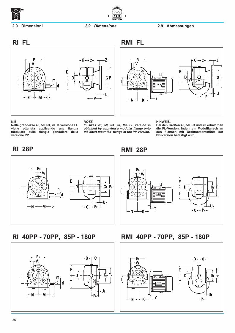
RI 28P
RMI 40PP - 70PP, 85P - 180P
RMI FL
RMI 28P
RI 40PP - 70PP, 85P - 180P
RI FL
2.9 Dimensions2.9 Dimensioni 2.9 Abmessungen
NOTE.
In sizes 40, 50, 63, 70, the FL version is
obtained by applying a modular flange onto
the shaft-mounted flange of the PP version.
HINWEIS.
Bei den Größen 40, 50, 63 und 70 erhält man
die FL-Version, indem ein Modulflansch an
den Flansch mit Drehmomentstütze der
PP-Version befestigt wird.
N.B.
Nelle grandezze 40, 50, 63, 70 la versione FL
viene ottenuta applicando una flangia
modulare sulla flangia pendolare della
versione PP.
37
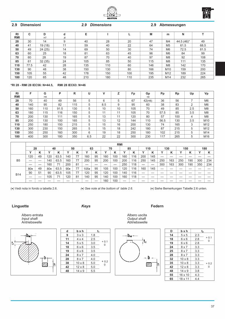
RI
RMI
F G
H8
P R U V Z Fp Gp
h8
Pp Rp Up Vp
28 70 40 49 56 5 6 5 67 42(H8) 36 56 7 M6
40 140 95 82 115 5 8.5 9 95 60 38 83 2 M6
50 160 110 91.5 130 5 10 10 105 70 49 85 2.5 M8
63 180 115 116 150 5 11 11 105 70 57.5 85 3.5 M8
70 200 130 111 165 5 13 11 120 80 57 100 4 M8
85 200 130 100 165 5 13 12 144 110 56.5 130 3.5 M10
110 250 180 150 215 5 15 16 200 130 74 165 3 M12
130 300 230 150 265 5 15 18 242 180 87 215 5 M12
150 350 250 160 300 6 19 18 250 180 102 215 5 M14
180 400 300 180 350 6.5 22 22 300 230 117 265 5 M16
RI
RMI
C D
H7
d
j6
E I L M m N T
28 30 14 9 40 28 20 47 M4 44.5 (46)* 49
40 41 19 (18) 11 59 40 22 64 M5 61.5 68.5
50 49 24 (25) 14 69 50 30 74 M6 72.5 81.5
63 60 25 18 81 63 45 96 M6 84 99
70 60 28 19 87 70 40 97 M8 92 108
85 61 32 (35) 24 105 85 50 115 M8 111 135
110 77.5 42 28 135 110 60 146 M8 142 170
130 90 48 38 150 130 80 166 M10 159 200
150 105 55 42 178 150 100 195 M12 189 224
180 120 65 48 210 180 110 235 M14 232 265
2.9 Dimensions2.9 Dimensioni 2.9 Abmessungen
Keys FedernLinguette
D b x h t2
14 5 x 5 2.3+ 0.1
018 6 x 6 2.8
19 6 x 6 2.8
24 8 x 7 3.3
25 8 x 7 3.3
+ 0.2
0
28 8 x 7 3.3
32 10 x 8 3.3
35 10 x 8 3.3
42 12 x 8 3.3
48 14 x 9 3.8
55 16 x 10 4.3
65 18 x 11 4.4
d b x h t1
9 3 x 3 1.8
+ 0.1
0
11 4 x 4 2.5
14 5 x 5 3.0
18 6 x 6 3.5
19 6 x 6 3.5
24 8 x 7 4.0
+ 0.2
0
28 8 x 7 4.0
38 10 x 8 5.0
42 12 x 8 5.0
48 14 x 9 5.5
Albero uscitaOutput shaftAbtriebswelle
Albero entrataInput shaftAntriebswelle
*RI 28 - RMI 28 IEC56: N=44.5, RMI 28 IEC63: N=46
RMI
28 40 50 63 70 85 110 130 150 180
Y K Y K Y K Y K Y K Y K Y K Y K Y K Y K
B5
120 49 120 63.5 140 77 160 95 160 100 160 116 200 145 — — — — — —
— — 140 63.5 160 77 200 95 200 100 200 116 250 145 250 163 250 190 300 234
— — 160 71 200 81 — — — — 250 118 — — 300 163 300 190 350 234
B14
80� 49 80� 63.5 90� 77 105� 95 105 100 120 116 160 145 — — — — — —
90 51 90 63.5 105 77 120 95 120 100 140 116 — — — — — — — —
— — 105 71 120 81 140 95 140 100 160 118 — — — — — — — —
— — — — — — — — 160 100 — — — — — — — — — —
(�) See note at the bottom of table 2.6. (�) Siehe Bemerkungen Tabelle 2.6 unten.(�) Vedi nota in fondo a tabella 2.6.
38
RI
RMI
F G
H8
P R U V Z C D
H7
d
j6
E I L M m N T
28 F1 80 50 53 62 4 6 7 30 14 9 40 28 20 47 M4 44.5(46)* 49
40F1
F2
106120
6080
6962
87100
55
8.59
99
4119 (18)
11 59 40 22 64 M5 61.5 68.5
50
F1
F2
F3
125125140
707095
937381
90100115
544
10.599
1099
4924 (25)
14 69 50 30 74 M6 72.5 81.5
63
F1°
F2°
F3°
175200160
115130110
8610282
150165130
555
111310
111111
60 25 18 81 63 45 96 M6 81 99
70
F1°
F2°
F3
175175160
115115110
11685101
150150130
556
111111
101011
6028
19 87 70 40 97 M8 92 108
85
F1
F2
F3
200210160
130152110
14112091
165176130
655
1313
11.5
121410
6132 (35)
24 105 85 50 115 M8 111 135
110
F1
F2
F3
200270270
130170170
115132178
165230230
51010
1313.513.5
121818
77.5 42 28 135 110 60 146 M8 142 170
180 F2 400 300 150 350 6.5 22 22 120 65 48 210 180 110 235 M14 232 265
0+ 9
RMI F1 - F2 - F3RI F1 - F2 - F3
2.9 Dimensions2.9 Dimensioni 2.9 Abmessungen
NOTE.
F1, F2 and F3 versions that are marked with
(°) are obtained by applying a modular flange
onto the shaft-mounted flange of the PP
version.
Non standard versions (on request) Spezialausführungen (auf Anfrage)Versioni speciali (a richiesta)
*RI 28 - RMI 28 IEC56: N=44.5, RMI 28 IEC63: N=46
HINWEIS.
Die mit (°) gekennzeichneten Versionen F1, F2
und F3 erhält man, indem ein Modulflansch an
den Flansch mit Drehmomentstütze der
PP-Version befestigt wird.
N.B.
Le versioni F1, F2, F3 contrassegnate con il
simbolo (°) sono ottenute applicando una
flangia modulare sulla flangia pendolare
della versione PP.
0+ 6
RMI
28 40 50 63 70 85 110 130 150 180
Y K Y K Y K Y K Y K Y K Y K Y K Y K Y K
B5
120 49 120 63.5 140 77 160 95 160 100 160 116 200 145 — — — — — —
— — 140 63.5 160 77 200 95 200 100 200 116 250 145 250 163 250 190 300 234
— — 160 71 200 81 — — — — 250 118 — — 300 163 300 190 350 234
B14
80� 49 80� 63.5 90� 77 105� 95 105 100 120 116 160 145 — — — — — —
90 51 90 63.5 105 77 120 95 120 100 140 116 — — — — — — — —
— — 105 71 120 81 140 95 140 100 160 118 — — — — — — — —
— — — — — — — — 160 100 — — — — — — — — — —
(�) See note at the bottom of table 2.6. (�) Siehe Bemerkungen Tabelle 2.6 unten.(�) Vedi nota in fondo a tabella 2.6.
39
RI - RMI
28 40 50 63 70 85 110 130 150 180
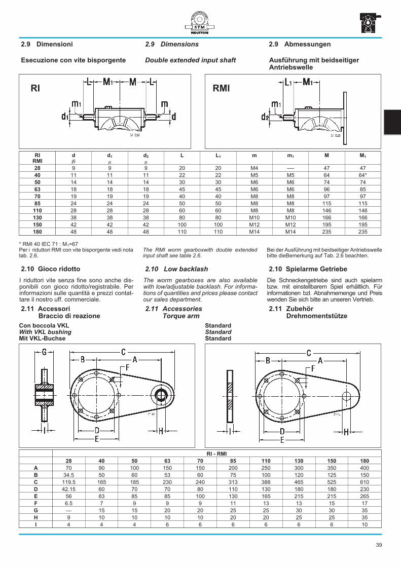
A 70 90 100 150 150 200 250 300 350 400
B 34.5 50 60 53 60 75 100 120 125 150
C 119.5 165 185 230 240 313 388 465 525 610
D 42.15 60 70 70 80 110 130 180 180 230
E 56 83 85 85 100 130 165 215 215 265
F 6.5 7 9 9 9 11 13 13 15 17
G — 15 15 20 20 25 25 30 30 35
H 9 10 10 10 10 20 20 25 25 35
I 4 4 4 6 6 6 6 6 6 10
2.11 Accessories
Torque arm
2.11 Accessori
Braccio di reazione
2.11 Zubehör
Drehmomentstütze
Con boccola VKL
With VKL bushing
Mit VKL-Buchse
Standard
Standard
Standard
Double extended input shaft
RI
RMI
d
j6
d1
j6
d2
j6
L L1 m m1 M M1
28 9 9 9 20 20 M4 —- 47 47
40 11 11 11 22 22 M5 M5 64 64*
50 14 14 14 30 30 M6 M6 74 74
63 18 18 18 45 45 M6 M6 96 85
70 19 19 19 40 40 M8 M8 97 97
85 24 24 24 50 50 M8 M8 115 115
110 28 28 28 60 60 M8 M8 146 146
130 38 38 38 80 80 M10 M10 166 166
150 42 42 42 100 100 M12 M12 195 195
180 48 48 48 110 110 M14 M14 235 235
RMIRI
Ausführung mit beidseitiger
Antriebswelle
Esecuzione con vite bisporgente
2.9 Dimensions2.9 Dimensioni 2.9 Abmessungen
Die Schneckengetriebe sind auch spielarmbzw. mit einstellbarem Spiel erhältlich. Fürinformationen bzl. Abnahmemenge und Preiswenden Sie sich bitte an unseren Vertrieb.
2.10 Spielarme Getriebe
I riduttori vite senza fine sono anche dis-ponibili con gioco ridotto/registrabile. Perinformazioni sulle quantità e prezzi contat-tare il nostro uff. commerciale.
2.10 Gioco ridotto
The worm gearboxes are also availablewith low/adjustable backlash. For informa-tions of quantities and prices please contactour sales department.
2.10 Low backlash
Bei der Ausführung mit beidseitiger Antriebswellebitte dieBemerkung auf Tab. 2.6 beachten.
* RMI 40 IEC 71 : M1=67Per i riduttori RMI con vite bisporgente vedi notatab. 2.6.
The RMI worm gearboxwith double extendedinput shaft see table 2.6.
40
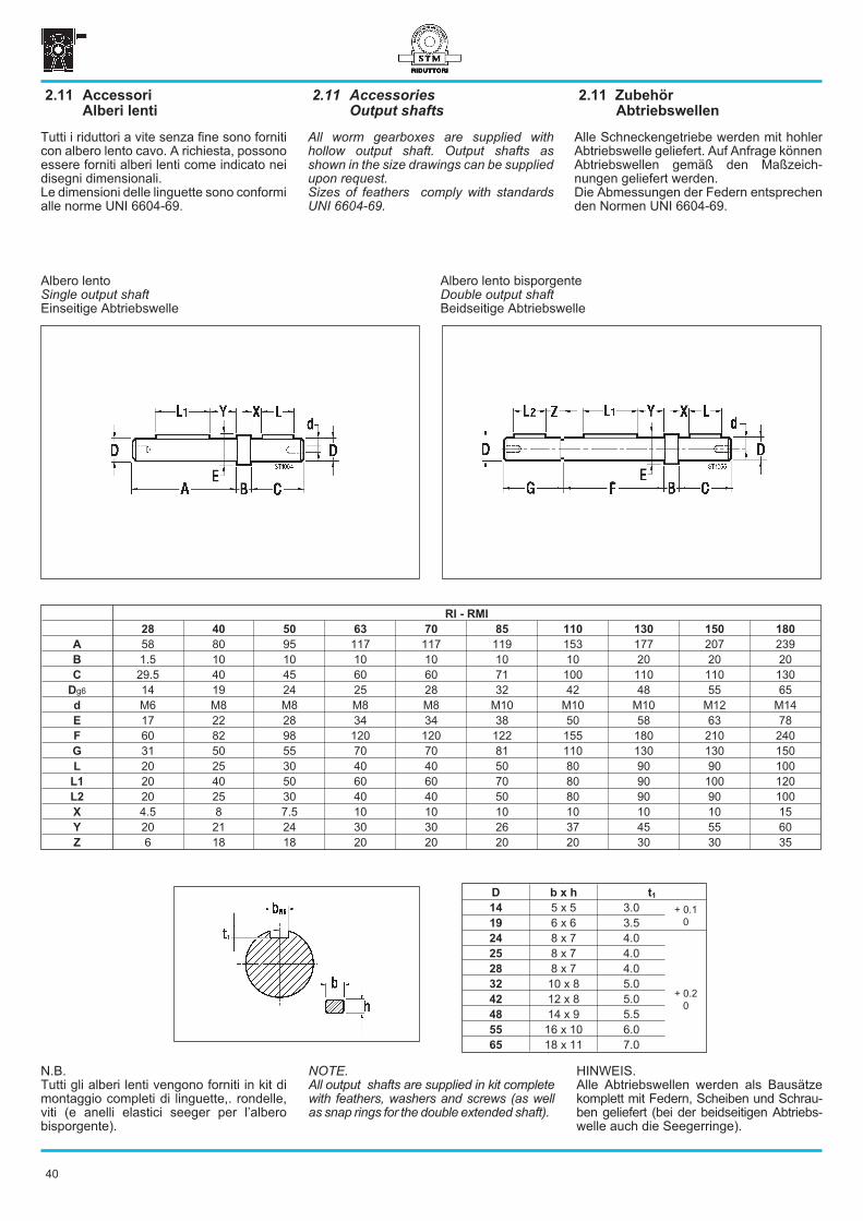
2.11 Accessories
Output shafts
2.11 Accessori
Alberi lenti
2.11 Zubehör
Abtriebswellen
All worm gearboxes are supplied withhollow output shaft. Output shafts asshown in the size drawings can be suppliedupon request.Sizes of feathers comply with standardsUNI 6604-69.
RI - RMI
28 40 50 63 70 85 110 130 150 180
A 58 80 95 117 117 119 153 177 207 239
B 1.5 10 10 10 10 10 10 20 20 20
C 29.5 40 45 60 60 71 100 110 110 130
Dg6 14 19 24 25 28 32 42 48 55 65
d M6 M8 M8 M8 M8 M10 M10 M10 M12 M14
E 17 22 28 34 34 38 50 58 63 78
F 60 82 98 120 120 122 155 180 210 240
G 31 50 55 70 70 81 110 130 130 150
L 20 25 30 40 40 50 80 90 90 100
L1 20 40 50 60 60 70 80 90 100 120
L2 20 25 30 40 40 50 80 90 90 100
X 4.5 8 7.5 10 10 10 10 10 10 15
Y 20 21 24 30 30 26 37 45 55 60
Z 6 18 18 20 20 20 20 30 30 35
Albero lento bisporgenteDouble output shaftBeidseitige Abtriebswelle
Albero lentoSingle output shaftEinseitige Abtriebswelle
NOTE.All output shafts are supplied in kit completewith feathers, washers and screws (as wellas snap rings for the double extended shaft).
D b x h t1
14 5 x 5 3.0 + 0.1
019 6 x 6 3.5
24 8 x 7 4.0
25 8 x 7 4.0
+ 0.2
0
28 8 x 7 4.0
32 10 x 8 5.0
42 12 x 8 5.0
48 14 x 9 5.5
55 16 x 10 6.0
65 18 x 11 7.0
Alle Schneckengetriebe werden mit hohlerAbtriebswelle geliefert. Auf Anfrage könnenAbtriebswellen gemäß den Maßzeich-nungen geliefert werden.Die Abmessungen der Federn entsprechenden Normen UNI 6604-69.
Tutti i riduttori a vite senza fine sono forniticon albero lento cavo. A richiesta, possonoessere forniti alberi lenti come indicato neidisegni dimensionali.Le dimensioni delle linguette sono conformialle norme UNI 6604-69.
HINWEIS.Alle Abtriebswellen werden als Bausätzekomplett mit Federn, Scheiben und Schrau-ben geliefert (bei der beidseitigen Abtriebs-welle auch die Seegerringe).
N.B.Tutti gli alberi lenti vengono forniti in kit dimontaggio completi di linguette,. rondelle,viti (e anelli elastici seeger per l’alberobisporgente).