Embed Size (px)
Citation preview
ENGINEERING DESIGN FILE
Problem Statement:
Design iifiing lugs with tank remforcing pads that can be welded to the PM-?A top and bottom half tanks and used to attach the rigging to lift the half tanks.
Surnmarv of Conclusions:
EDF 096-012A Rev. No. 0 Page 1 of8
EDF Titie: TSF-26 PM2A HALF-TANK LIFTING LUGS DESIGK Project Xo.: 2000-096 Proiect Specific Activity: PM2A HALF TANK LETING LUGS DES~GN AND CALCULATIONS
1 Project Title: OU 1-10, TSF-26 REMEDIATION
I
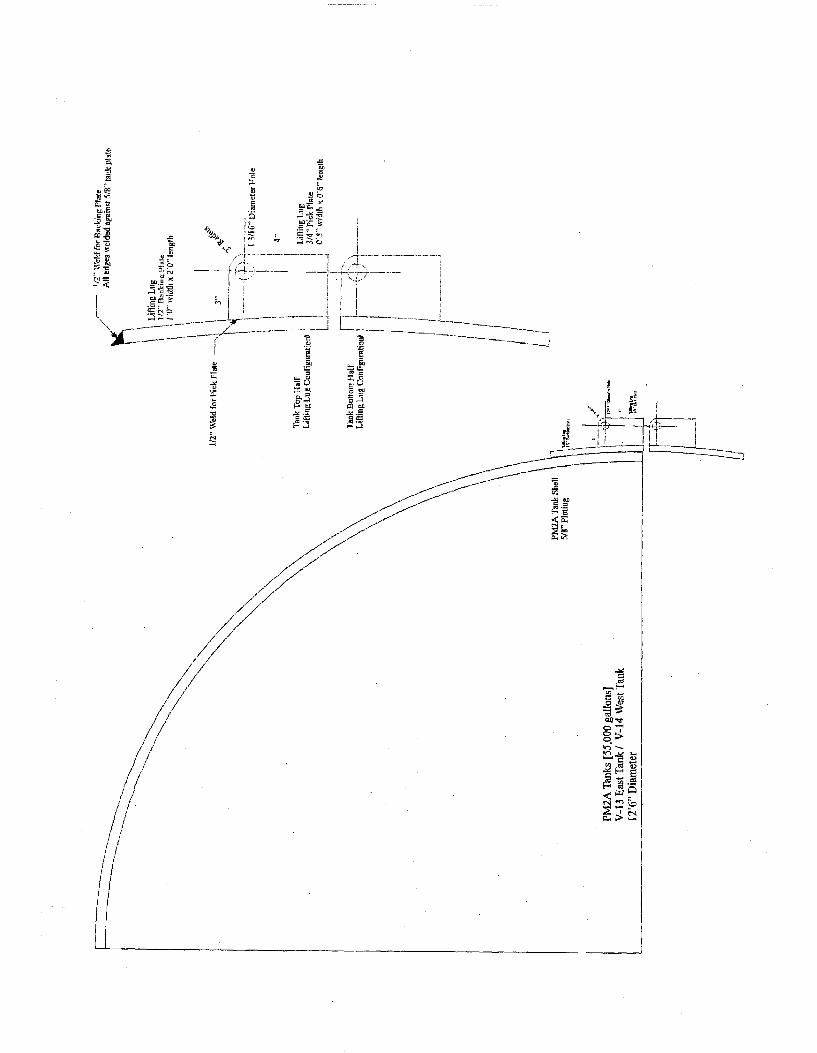
The design chosen is to weld !h rnch steel plates 2 ft long and 1 ft high to the outer surface of the tank at the locations of the emforcement ribs where the rigging is to be attached and to weld 3/4 inch lugs to the plate to attach the rigging. A finite
[INDEPENDENT I I I
Distribution:
EDF Title: TSF-26 PM2A HALF-TANK LIFTING LUGS DESIGN EDF NO. 096-Q12A Project No.: 2000-096 Rev. No.: 0 Project Title: OU 1-10, TSF-26 REMEDIATION Page 2 of8 Prepared by: L. Magleby Date: 03-Dec-03 Checked by: Kevin Shaber Date:03-Dec-03
PROBLEM STA TEMENT: TSF-26 Site Remediation Operations require the cutting and removal of the PM2A Tanks [V-13 (East Tank) and V-14 (West Tank)] halves in conjunction with waste removal operations.
Design lifting lugs with tank reinforcing pads that can we welded to the PM-2A top and bottom half tanks and used to attach the rigging to lift the half tanks. Ths is an alternate method
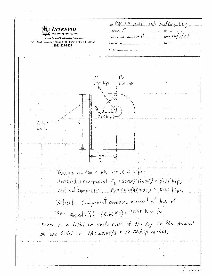
The half tanks each weigh 33,425 lbs. The half tanks are to be lifted with a mobile crane using a single hook. The tanks are to be rigged near the two end internar rib stiffeners of the tank each located about 11 feet from their respective ends. The rigging will use a spreader bar so that the lifting points will be directly above the rigging location at the stiffeners. The length of the rigging from the spreader bar to the tank will be of a length so that the angle of the rigging from the lugs welded to each side of the tank, about 12 % feet apart, to the attachment points on the spreader will be about 35” fiom vertical.
ASSUMPTIONS: The Assumptions utilized in the performance of these calculations are outlined below:
0
0
rn
Thckness of the PM2A Tank walls to be 5/8” Thickness of P W A Tank Exterior TAR Coating was confirmed to be 1/16” and NOT the previously reported 1’2” to 1” kckness range. Calculated Weight of the PM2A Tank Half is 33,425 pounds
REFERENCES: EDF-0960012 Rev.2 DOE-ID Order 440C
ASME 330.20a-2001 DOE-STD-1090-2001
ACCEPTANCE CRITERIA: The stresses in the tank wall will be less than 113 of yield stress to meet the intent of the DOE-STD-1090 reference to ASMEB30.20a. The design of the pads to be welded to the tank wall and the lifting lugs will have a factor of safety of 3 to be in compliance with the DOE-STD-1090 reference to ASMEB30.20a.
DESCHPTION OF DESIGN: The design is shown on Drawing M-6 included in the design submittal and is shown on the attached sketch. The design is to weld a ?4 inch steel plate 2 ft long by 1 ft high to the outside surface of the half tanks at the location of the rigging points at the end stiffeners located about 11 feet from thier respective ends. Lifting lugs fabricated from 3/4 inch steel plate are welded to the ?4 inch steel plate at the rigging attachment plates. The lifting lugs are sized for attaching 1 inch shackles.
EDF Title: TSF-26 PM2A HALF-TANK LIFTING LUGS DESIGN Project No.: 2000-096 Project Title: OU 1 - 10, TSF-26 REMEDIATION Prepared by: L. Magleby Date: 03-Dec-03 Checked by: Kevin Shaber
EDF NO. 096-012A 0 Rev. KO.:
Page 3 of8 Date: 03 -Dec-03
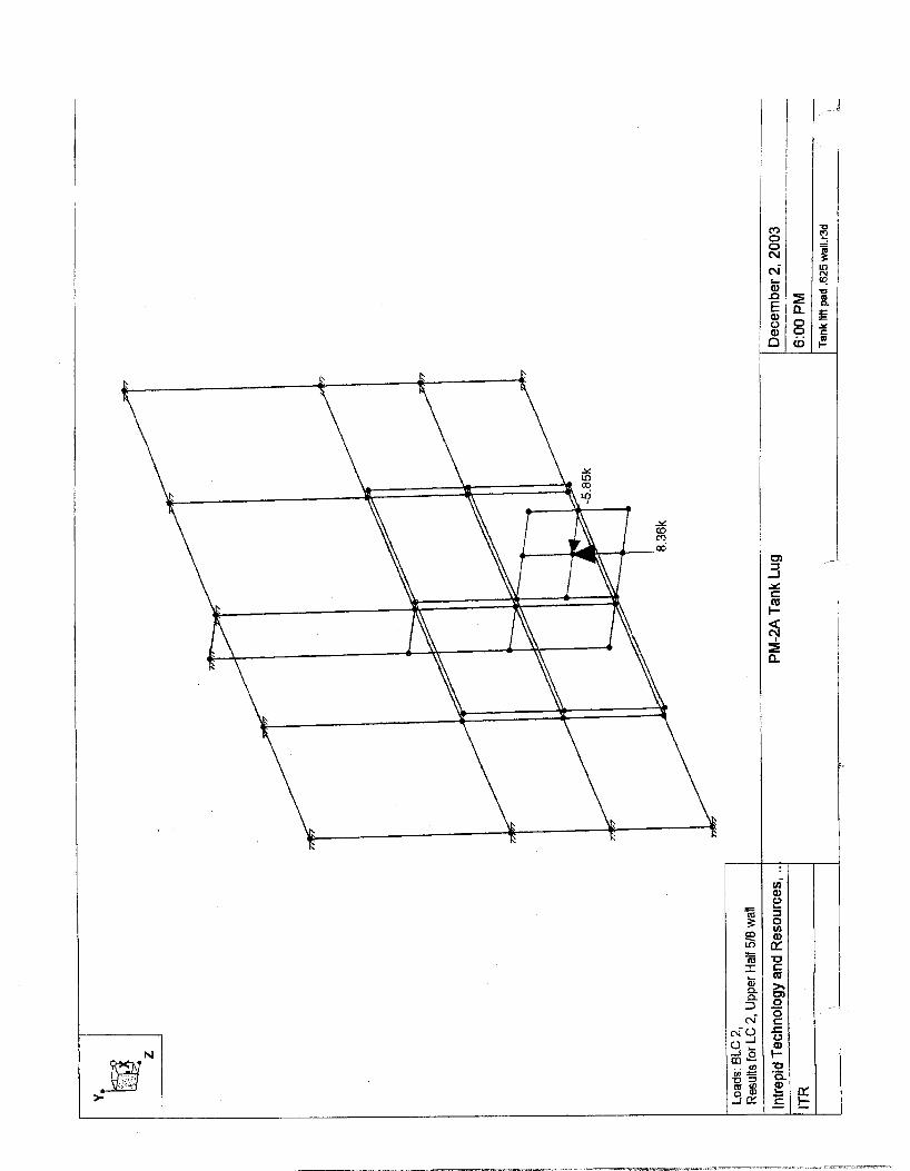
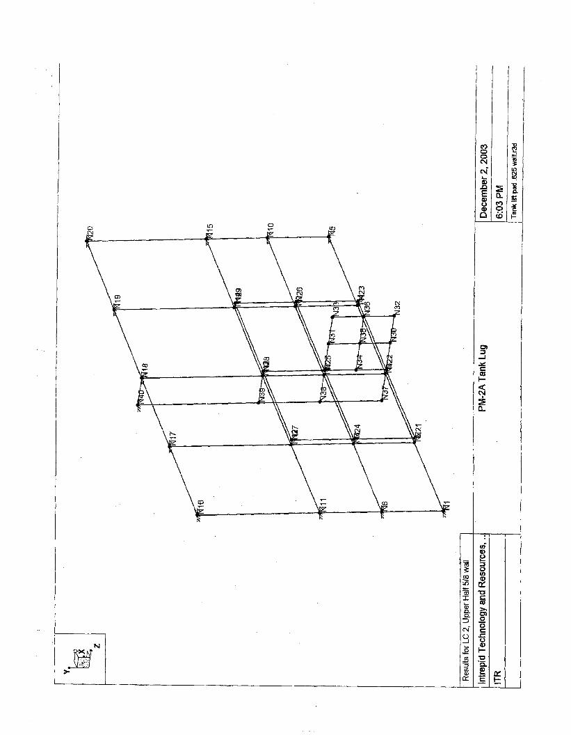
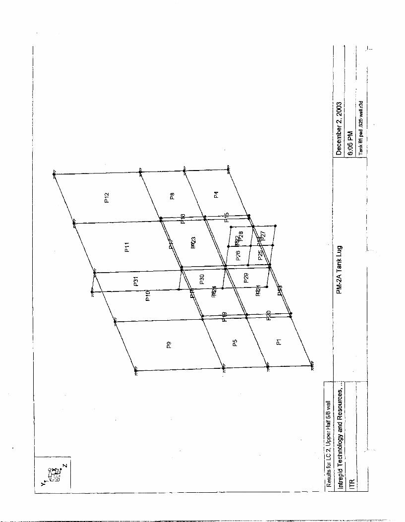
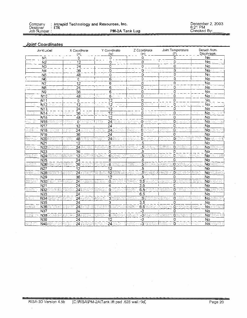
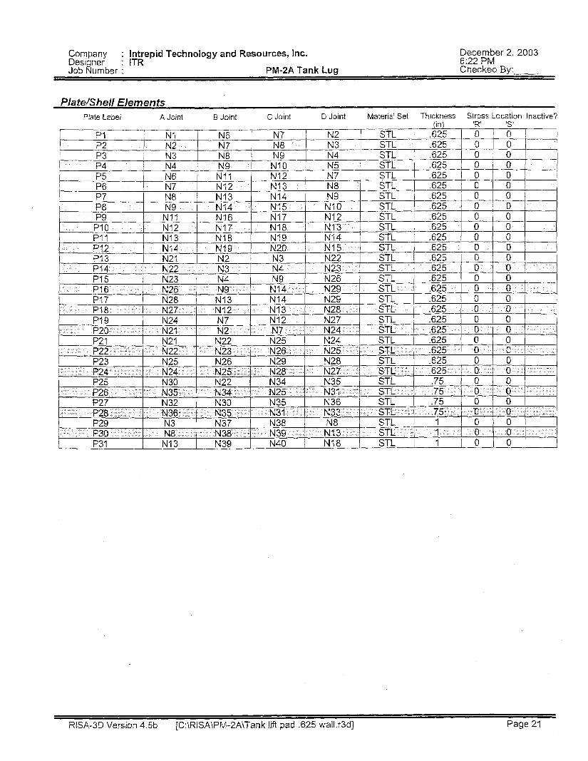
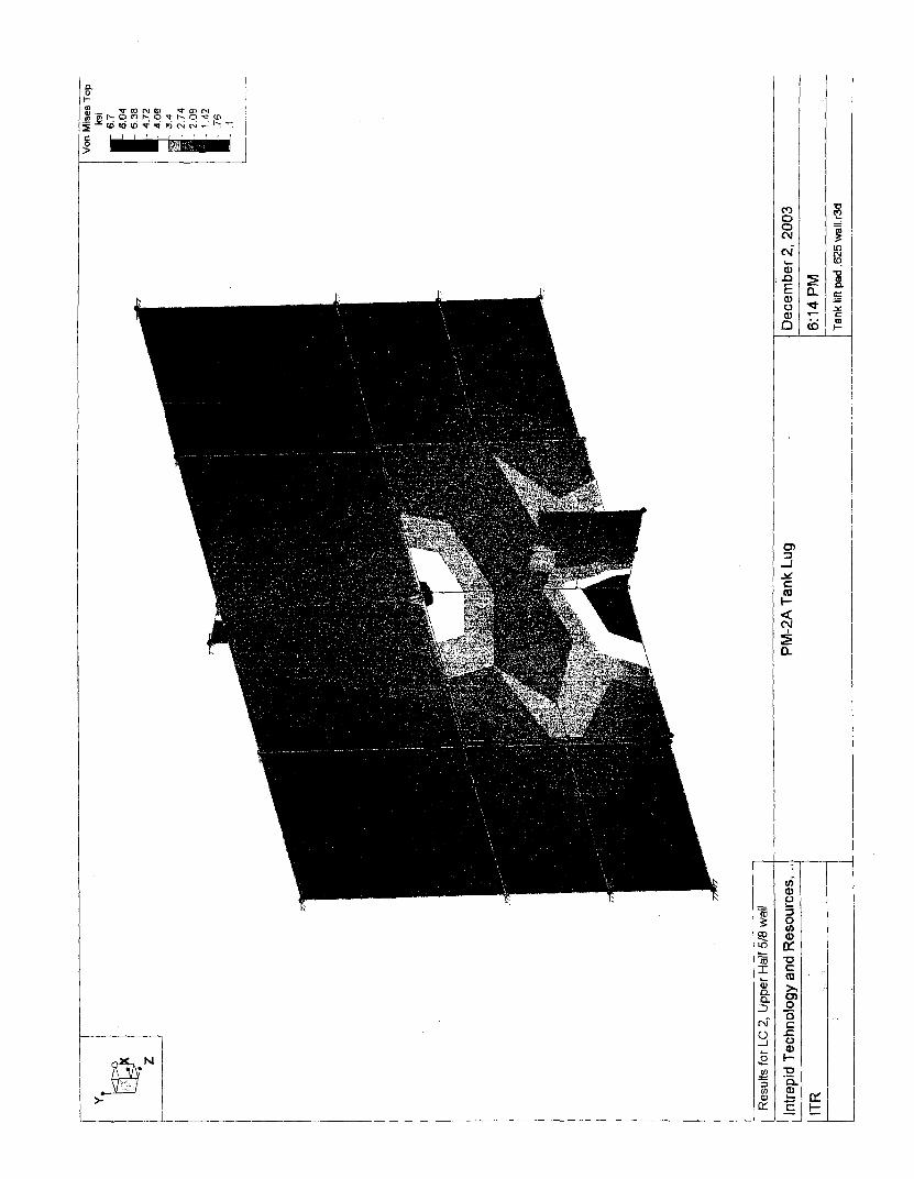
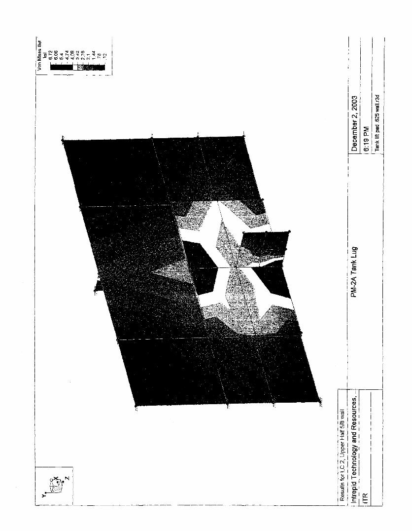
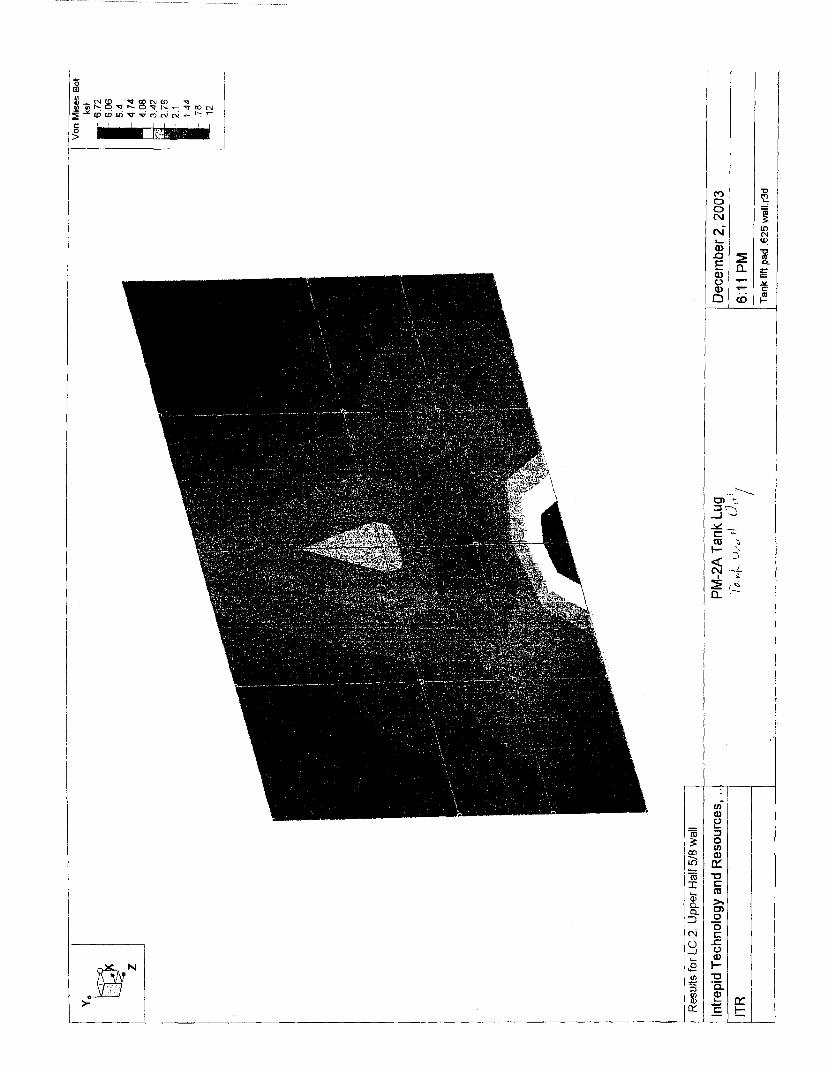
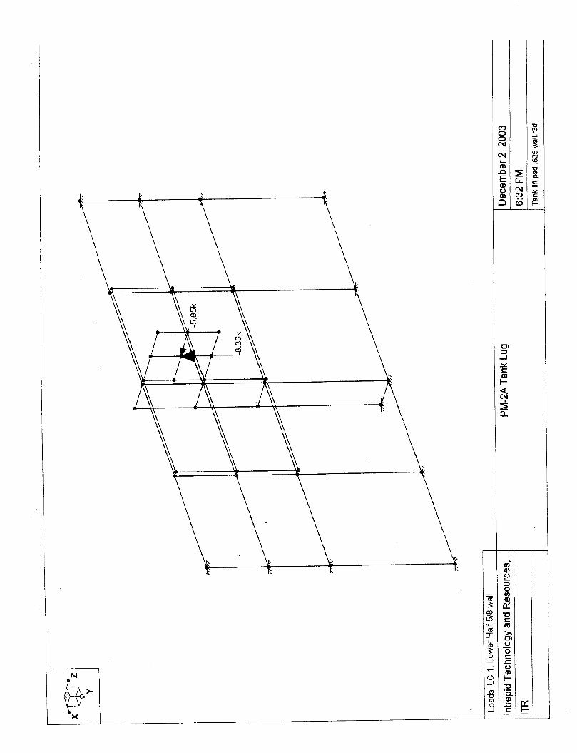
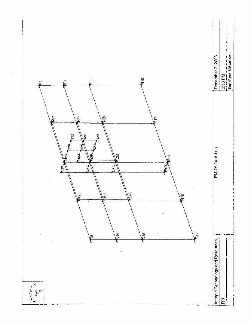
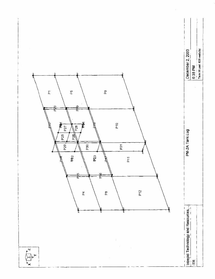
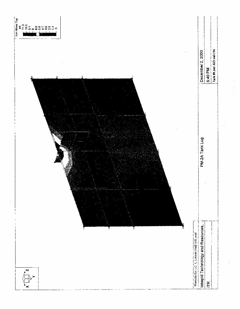
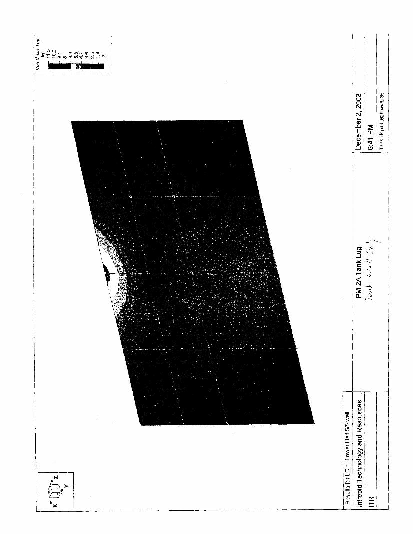
DESCluPTIOhJ OF AR'ALYSIS: A three dimensional finite element model was made of the plate attachment to the tank outer surface using the RISA 3D structural analysis program. The support of the plate by the tank wall was approximated by modeling a section of the tank wall one foot greater than the size of the plate at each side and fixing the outer edges. Flat plates were used in the model to simplifjl the modeling but c w e d plates would be expected to be stronger; therefore, the model is considered to be conservative. The model is rather coarse in that the number of flat plates used to formulate the model is not large. However, care was taken in formulating the model to assure that there were sufficient plates so that parts were connected by at least the node points. The model is shown in the attachment titled RISA 3D Analysis.
The design is the same for the top half tank and the bottom half tank. However, the direction of the load is away from the free edge for lifting the top half tank and towards the free edge for the bottom half tank. Analyses were made with the force in both directions.
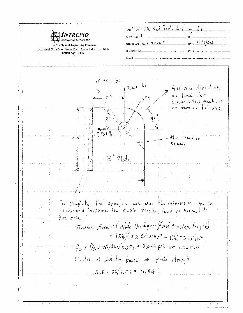
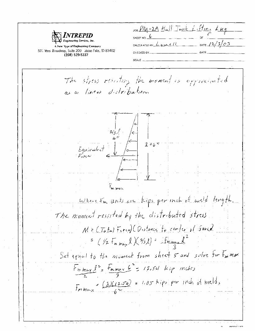
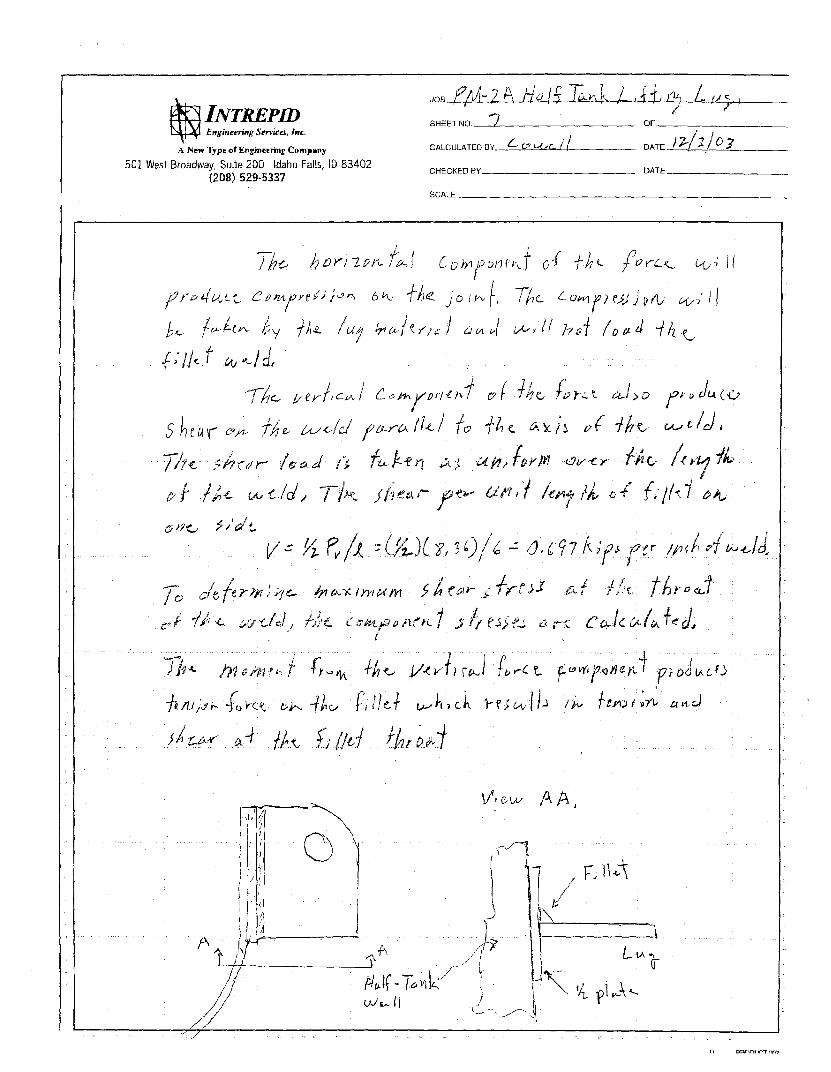
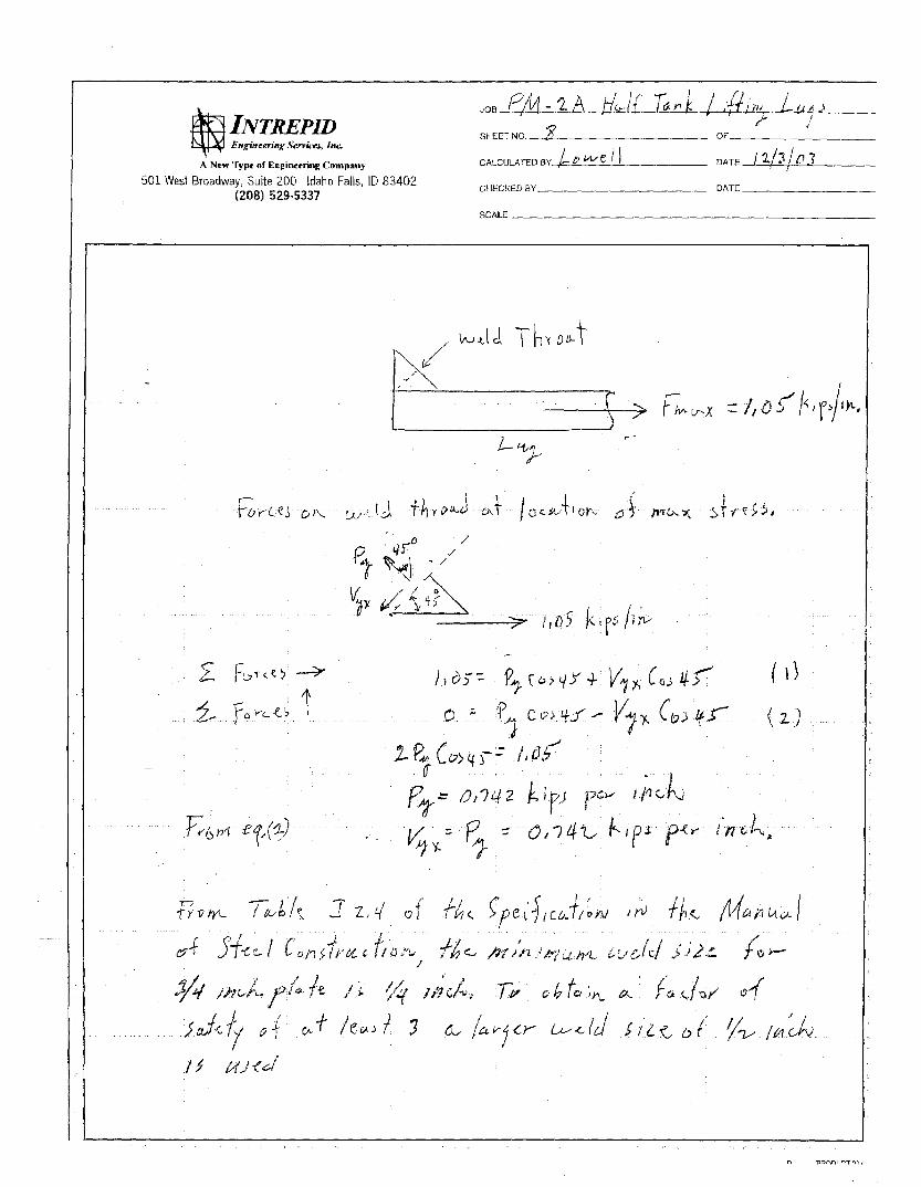
The lifting lug was analyzed manually as was done in the design of the lugs for the spreader bar. See the EDF 096-012 included in the Design Submittal. The analyses for the lug for this application are included in the Attachment Lifting Lug Analysis.
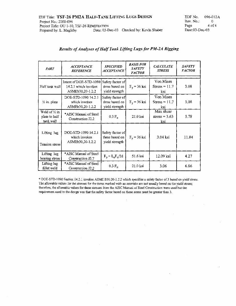
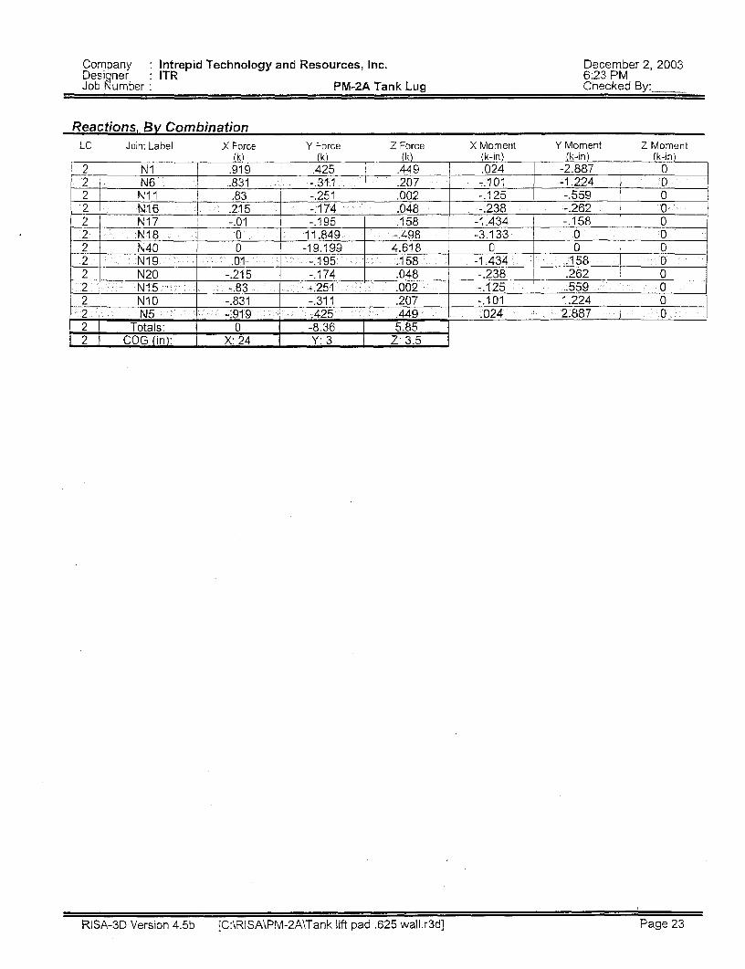
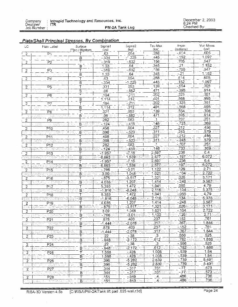
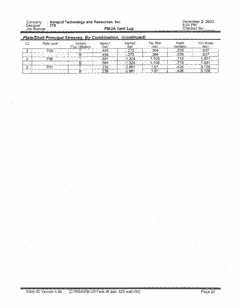
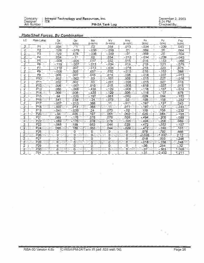
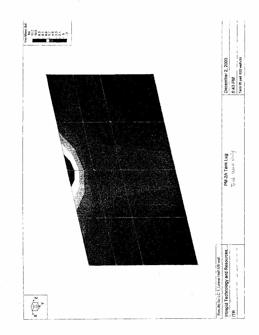
ANALYSIS RESULTS: The results of the analyses are shown in the attached table, Results of Analyses of Half Tank Lifting Lugs for PM-2A Rigging. The stresses were higher for the bottom half tank with the lifting force towards the free edge. The results are in the table for this case. The complete RISA 3D results for both cases are included in the attached RISA 3D Analysis. The RISA 3D results given in the results table only gives the stresses at the center of the small plates used to formulate the model. The highest stresses usually occw at the edges of the small plates. The contour plots of the results provided by RISA 3D show extrapolation of the stresses to ail points in the model. The stresses for the half tank wall and the ?4 inch plate welded to the half tank were taken from the counter plots. Narrow ?4 plates were used to model the welds between the half thank wall and the ?4 inch plate and the stress at the center of these narrow plates from the results table were used for the welds.
The result is the table showing that the acceptance criteria are met and the design is acceptable.
EDF Title: TSF-26 PM2A KALF-TANK LIFTING LUGS DESIGN Project No.: 2000-096 Project Tide: OU 1-1 0, TSF-26 REMEDIATION Prepared by: L. Magleby Date: 03-Dec.-03 Checked by: Kevin Shaber
A CCEPTANCE I PART 1 REFERENCE
Results of Analyses of Half Tank Li$iizg Lugs for PM-2A Ri'ing
SPECIFIED A CCEPTANCE
I I I
F, = 36 ksi Von Mises
Stress = 11.7 I 3.08
EDF NO. 096-012A Rev. No.: 0 Page 4 of4 Date:03-Dec-03
, Safety factor of three based on yield strength
, Half tank wal
Safety factor 01 three based on
' yield strength
0.3 F,
% in. plate
Weld of % in plate to half tank wall
Lifting lug
Tension stress
F, = 36 ksi
21.0 ksi
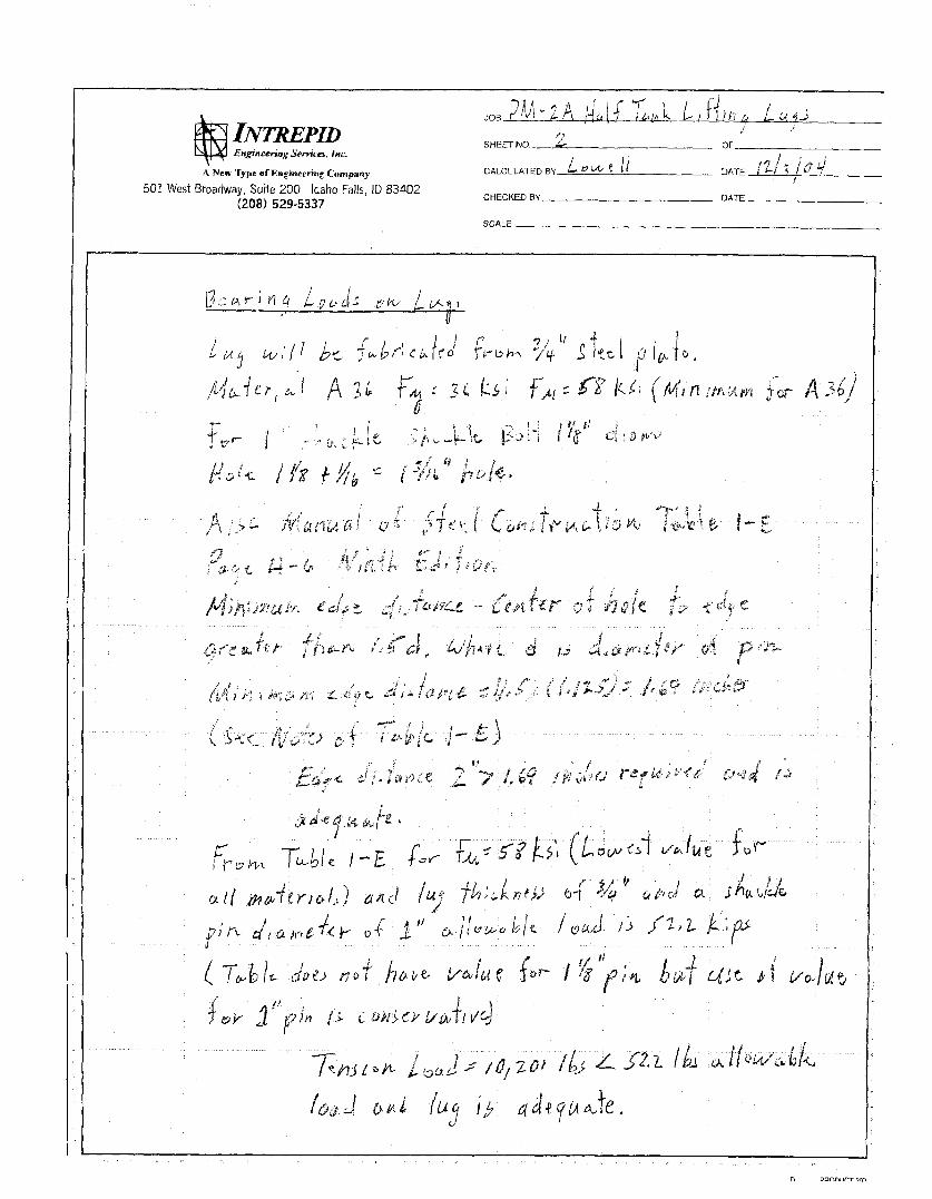
Lifting lug bearing stress
Lifting lug fillet weld
ksi Von Mises
ksi Max shear
ksi
Stress = 11.7 3.08
stress = 3.63 5.78
Intent of DOE-STD- 1090 14.2.1 which invokes ASMEb30,20-1.2.2
51.6 ksi
DOE-STD-1090 14.2.1 which invokes
ASMEb30.20-1.2.2
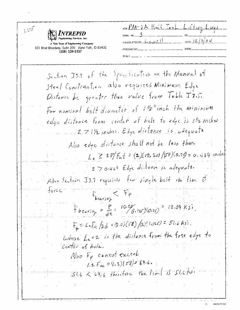
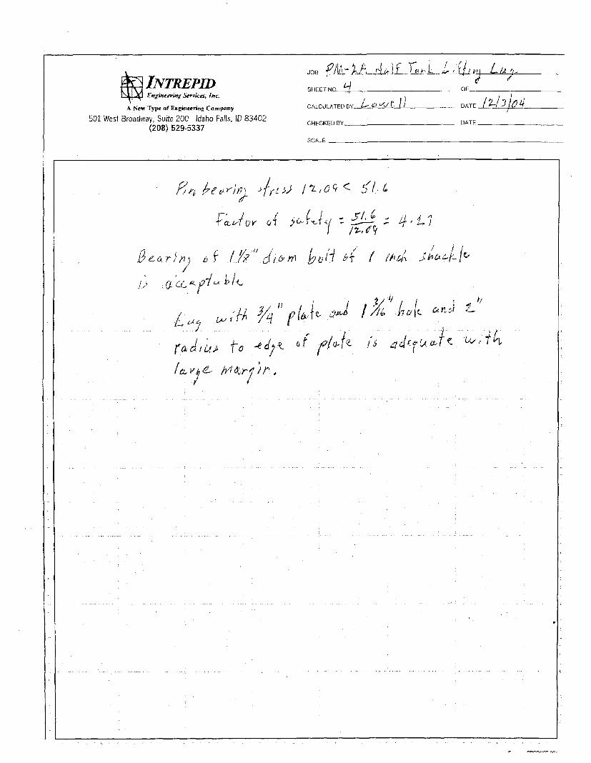
12.09 ksi 4.27
*MSC Manual of Steel Construction J2.2
21.0 ksi
DOE-STD-1090 14.2.1 which invokes
ASMEb30,20-1.2.2
3.06 6.86
*AISC Manual of Steel Construction 53.7
*AISC Manual of Steel Construction 52.2
Safety factor of three based on yield strength
F, = L$,/2d
0.3 F,
F, = 36 ksi 3.04 ksi 11.84
* DOE-STD-1090 Section 14.2.1 invokes ASh4E B30.20-1.2.2 which specifies a safety factor of3 based an veld stress. The allowable values for the stresses for the items marked with an asterisks are not usually based on the ve ld stress; therefore, the allowable values for these stresses €ram the AISC Manual of Steel Construction were used but the requirement used in the design was that the safety factor based on these stress must be greater than 3.
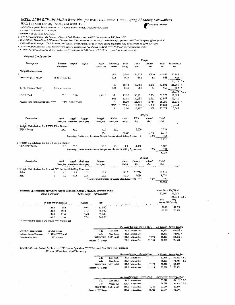
Original Conjigurafion
PM2A Tank 12.5 55.0
AssumeTank Ribs and Manways =: 7.0% Added Weght
Description widfh lettgfh height OinmlJcci) flincd /ref; (Imrnl/cc?)
2 Weight Calculations for RUBE THA Shelter T€IA 8 Meter 26.2 65.0
518 2160 0.06 0.38
112 20.40 0.n6 0.38
2,405.3 318 15.30 5/16 12.80 114 1030
3/16 1.65 1 IS 5.10
61,575 4 3 1 0 902 63
49,068 3,435 902 63
36,801 2,576 30,788 2,155 24,534 1,717 18,400 1,288 12,267 859
Weight Ta4 Added (Ibsl (I&
5.050 25.0 71.00 1,775
Tntal Y a l p M 2 A Ob,) (IbiJ
65.885 32,943 7
965 483 6
3hd2.5 ' 9 6
52,502 26,251 4 '165 483 6
26.734 4% 6 39,373 19.688 32,943 16.471 26,251 13,126 i 19688 9,844 13,126 6.563
Tofal Obsl
5,050 1,775
Percentage Contmgency for Added Weight Associated \mth LiftYIg Svstem => 5.0% 350 7.175
THA 22'0" Walls 16.0 35.0 35 0 16.0 8.0 4,480 4,500
4.730
2 Weight Calculations for RUBB Special Shelter
Percentage Contmgm$ foi Added Weight Associated with L m g System => S.O?& 230
weighf Descnphon width length thiekttess Volume Unit Prccasz Added Total
Lneal fen) (irnenl feu) ( I m L o l j m ) (cubic fen) I7bdCfl ow (IbsJ (Ibd
2 Sides 2 6 0 9.8 0 7 5 87 s 145 0 12,724 12,724 Ead 1 6 0 138 0 7 5 62.2 145.0 9,014 9,024
Percentage Canimgenc). for Added Steel Rem-orcmg ==> 4.505 980 22.728
Technical Specifications for Grove Mobile Hydraulic Crane GMK5240 1240 ton crane] Boom Extensiort Boom Angle Lift Clpncw
1Vdc Tank Hnl/?ank 52.502 26.751
ObsJ Rbs) 26,73./ 4 & 6
121.0 100.0 34.3 36,000 136.0 110.0 36.0 32,200 151.0 120.0 31.4 24,800
Distlnre trom UL Crnap to CIL s f h d -> (h-lined lrct)
145.8% ?'.9?h
V-14 WertTank 100.0 h-lineal feet 36,000 72.9% 4
RUBB TIL4 26.2' x 65.0 110.0 h-lineal fee: 7,175 32200 22.3% 4
Precast "C" Shape 110.0 h-lined feet 22,728 32.200 70.6%
Long High Capaciw Trailers Available => 2003 Fontaine Spedahed TDFT Telescopic Step, Drop Decl Extendable IO?" widel 48'48' deck! 8D.000 lbs capacihl . .
HonronidDmoncr - Cranelo Tank Li# Copncio Pcrccni loading
V-13 Ensf Tank 80.0 h-lined feet 53,000 50.4V4 4 & 6
V-14 Westlsnlt 100.0 h l n u l iect 36.000 71.3% 4 C 6
RUBB "A 26.2' I 65.0 110.0 h lndfer t 7,175 31,200 22.3%. Precast "C" Shape 110.0 hlnealfert 22,728 31,200 70.6%
V-34 West'Iank 100.0 h l n c n l lcrt 36,000 Y2.8"% 7 9r 6
RLBB THA 26.2' I 65.0 110.0 h-hea l feet 7,175 32,200 22.3% Precast "C" Shape 110.0 h-lincai feet ~2,728 32,20Q 70.6%
RISA 35 ANALYSIS
R E A 3D ANALYSIS
UPPER HALF TANK
I
I I E
Company : Intrepid Technology and Resources, Inc, December 2, 2003 Designer : ITR 6 2 1 PM Job Number : PM9A Tank Lug Checked By:
RISA-3D Version 4.5b [C:\RISA\PM-2A\Tank lift pad 3 2 5 wall.r3dJ Page 20
Company : Intrepid Technology and Resources, Inc. December 2, 2003 Designer : ITR 6:22 PM Job Number : P M 9 A Tank Lug Checked By.
RISA-3D Version 4.5b [C:\RfSA\PM-2A\Tank lift pad -625 wall.r3d] Page 21
Company : Intrepid Technology and Resources, Inc. December 2,2003 Designer : ITR 6:22 PM Job Number : PM-SA Tank Lug Checked By:
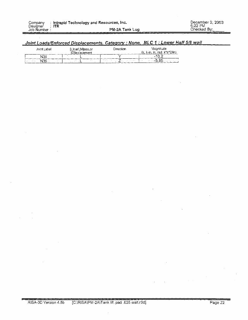
Joint LoaddEnforced Disdacements, Cafeaorv : None, BLC 1 : Lower Half 5/8 wall
RISA-3D Version 4.5b [C:\RISA\PM-2A\Tank lift pad .625 wall.r3d] Page 22
Company : Intrepid Technology and Resources, Inc. December 2, 2003 Designer : ITR 6123 PM Job Number : PM-%A Tank Lug Checked By:
Reactions, By Combination 2 Moment LC Joint Label X Force Y Force Z Force X Moment Y Mornen!
RtSA-3D Version 4.5b [C:\RISA\PM-2A\Tank lift pad ,625 wall.r3d] Page 23
Company : Intrepid Technology and Resources, Lnc. December 2,2003 Designer : ITR 6:24 PM Job Number : PM-2A Tank Lug Checked By:
RISA-3D Version 4.5b [C:\RISA\PM-2A\Tank l i f t pad 525 wall.r3d] Page 24
Company : Intrepid Technology and Resources, Inc. December 2,2003 Designer : ITR 6:24 PM Job Number : PM-SA Tank Lug Checked By:
PlatdShell Principal Stresses, Bv Combination, (continued) LC Plare Label Surface Sigma1 Sigma2 Tau Max Angle Von Mises
RISA-35 Version 4.5b [C:\RlSA\PM-ZA\Tank lift pad ,625 wall.r3d] Page 25
Company : Designer :
intrepid Technology and Resources, inc. ITR
December 6124 PM
2, 2003
Checked By: Job Number : PM-2A Tank Lug
Plate/Shell Forces. By Combination LC Plate Label Qx Mx MY Fx Fxv
RlSA-3D Version 4.5b [C:\RISA\PM-2A\Tank lift pad ,625 wall.r3d] Page 26
BN

a I
I R h s-
ic -
P
RlSA 3D ANALYSIS
LOWER HALF TANK
N ?
N 7
i-l
-0 c

Company : Intrepid Technology and Resources, Inc. December 2,2003 Designer : ITR 6:46 PM Job Number : PM-PA Tank lug Checked By:
Joint Coordinates Joint Label X Coordinate Y Coordinate Z Coordinate Joint Temperature Detach from
RISA-3D Version 4.5b [C:\RISA\PM-2A\Tank lift pad .625 wall.r3d] Page 1
Company : Intrepid Technology and Resources, hc. December 2, 2003 Designer : ITR 6:47 PM Job Number : PM-2A Tank Lug Checked By:
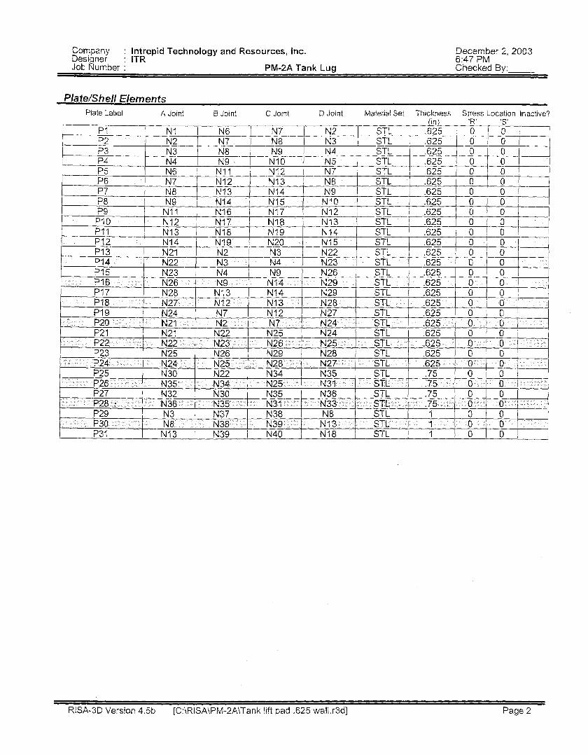
Pla te/S hell Eiernen ts Plate label A Joint B Joint C Joint D Joint Material Set Thickness Stress Location Inactive?
RISA3D Version 4.5b [C:\RISA\PM-2A\Tank lift pad ,625 wall.r3d] Page 2
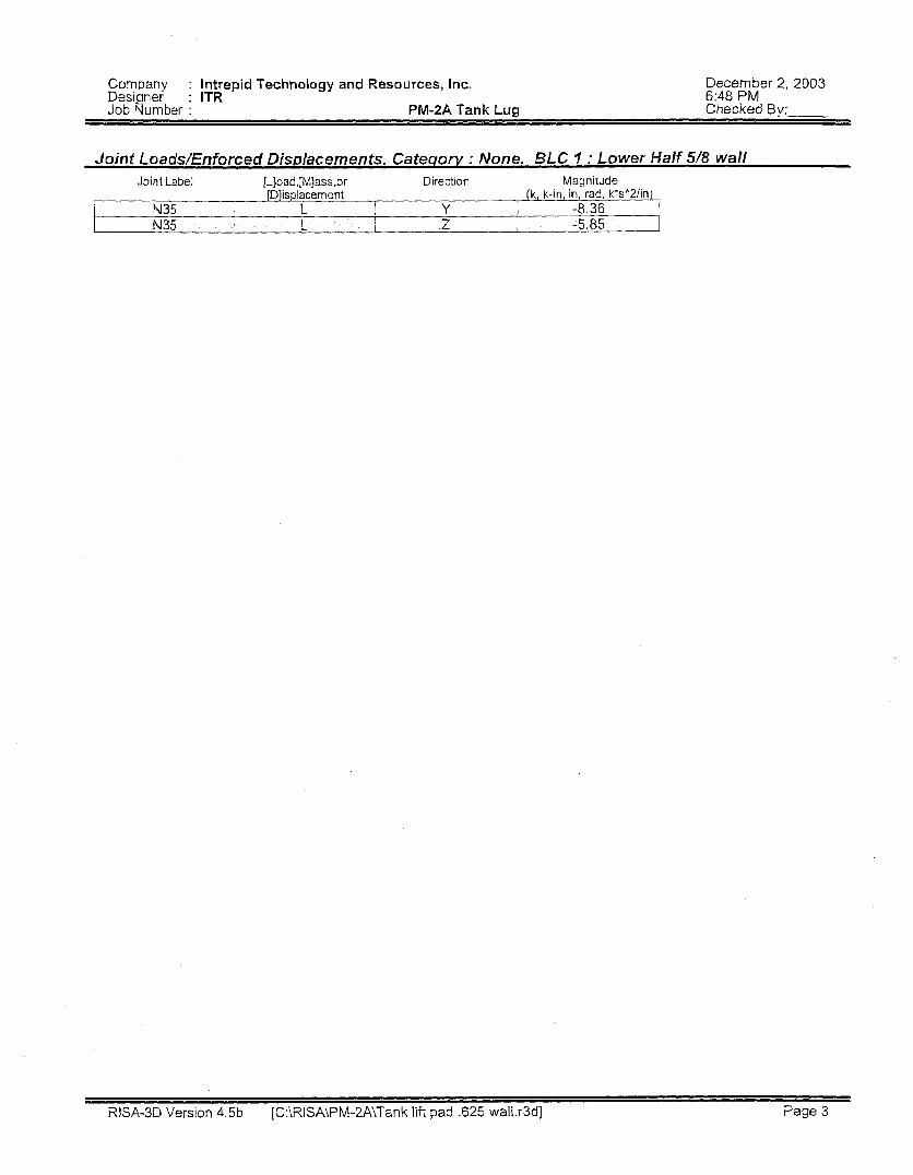
Company : Intrepid Technology and Resources, lnc, December 2, 2003 Designer : ITR 6:48 PM Job Number : PM-2A Tank Lug Checked By:
N35 L Y -8.36
RISA-3D Version 4.5b [C:\RISA\PM-2A\Tank lif t pad -625 wall.r3d] Page 3
N35 L z -5.85
Company : Intrepid Technology and Resources, Inc. December 2,2003 Designer : ITR 6:50 PM Job Number : PM-2A Tank Lug Checked By:
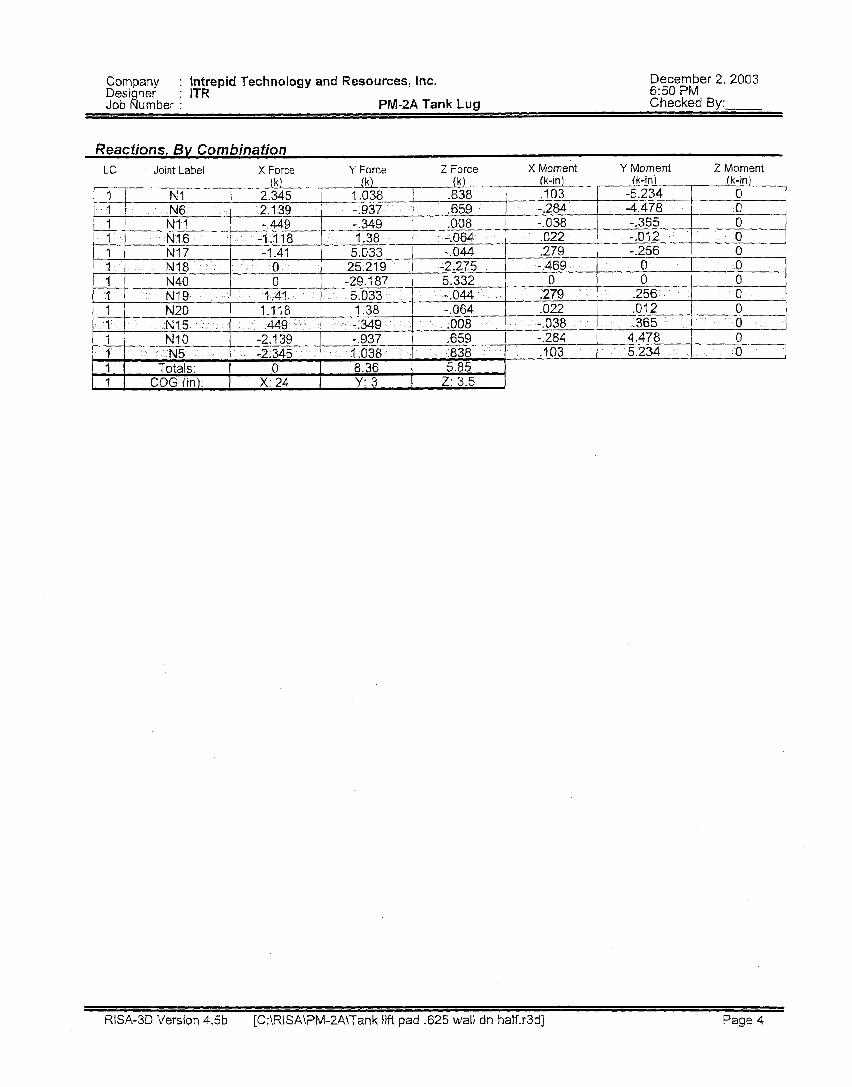
Reactions, By Combination LC Joint Label X Force Y Force Z Force X Moment Y Moment Z Moment
RISA-3D Version 4.5b [C:\RISA\PM-2A\Tank lift pad .625 wall dn half.r3d] Page 4
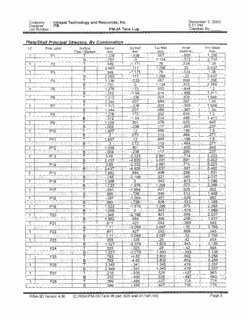
Company : Intrepid Technology and Resources, Inc. December 2,2003 Designer : ITR 6:51 PM Job Number : PM-2A Tank Lug Checked By:
RISA3D Version 4.5b [C:\RISA\PM-2A\Tank lift pad .625 wall dn half.r3d] Page 5
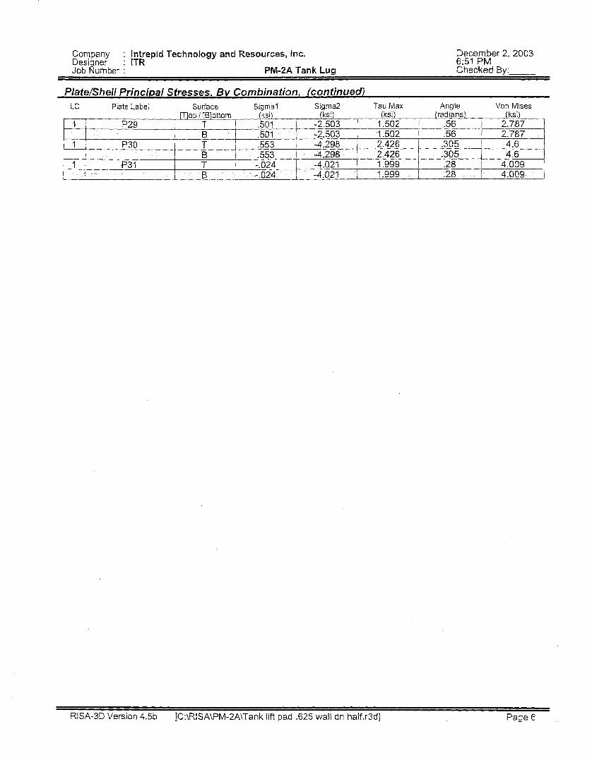
Company : Intrepid Technology and Resources, Inc. December 2,2003 Designer : ITR 6 5 1 PM Job Number : PM-PA Tank Lug Checked By:
PlatdShell Principal Stresses, 5 v Combinafion, (continued) Angle Von Mises LC Plate Label Surface Sigma1 Sigma2 Tau Max
~ ~ ~~
REA-3D Version 4.5b [C:\RlSA\PM-2A\Tank lift pad ,625 wall dn half.r3d] Page 6
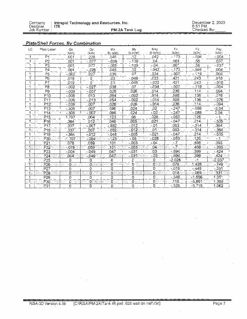
Company : Intrepid Technology and Resources, Inc. December 2,2003 Designer : ITR 6 5 1 PM Job Number : PM-2A Tank Lug Checked By:
RISA-3D Version 4.5b [C:\RISA\PM-2A!Tank lift pad ,625 wall dn half.r3d] Page 7
I f I
I r -
r

r IT
/1
m 0 0 N
cui
n E
L W
Q, 0 Q) n -
LIFTING LUG ANALYS1S
A New Type of Engineering Company
501 West Broadway, Suite 200 Idaho Falls, ID 83402 (208) 5e9-5337
L SHEETNO. i OF
CHECKED BY DATE
SCALE
JOB P M " 2 A / A I d ( -f l + L L , I h L . L f q 2 i
3 INTREPlD SHEETNO Lr OF EnglneerJn# Jervucs, InL.
I CALCULATED BY
CHECKED BY DATE
DATE #a/: / r : 4 ' 1
A New Type of Engmeenng Company
501 West Broadway, Suite 200 Idaho Falls, ID 83402 (208) 529-5337
SCALE
501 West Broadway, Suite 200 Idaho Falls, ID 83402 CHECKED BY DATE (208) 529-5337
SCALE
CHECKED BY DATE 501 West Broadway, Suite 200 Idaho Falls, ID 83402 (208) 529-5337
SCALE
INT'XEPD EnKineering Sen La, Inc.
A hew Type of Engineering Company
501 West Broadway, Suite 200 Idaho Falls, ID 83402 CHECKED BY DATE (208) 529-5347
SCALE
, i /' '7 ,' /
A New Type of Engineering Company
501 West Broadway, Suite 200 tdahD Falls, ID 83402 CHECKED BY DATE (208) 529-5337
SCALE
A New Type of Engineering Company
.+ r
SHEETNO 1 OF
CHECKED BY DATE 501 West Broadway, Suite 200 Idaho Falls, ID 83402 (208) 529-5337
SCALE
P
1NTXEPI.D Engineering Sen1L.a. Inc.
A New Type of Engineering Company
501 West Broadway, Suite 200 Idaho Falls, ID 83402 (208) 529-5337
SCALE

A New Type of Engineering Company
<* SHEET NO Y OF
CALCULATED BY < I DATE
CHECKED BY DATE 501 West Broadway, Suite 200 Idaho Fails, ID 83402
(208) 529-5337 SCALE
. c
INTRiPID Engineerinx Servica, Inc.
A 1Tew Type of Engineering Company
(208) 529-5337 501 West Broadway, Suite 200 Idaho Falls, ID 83402
SHEETNO )* Of
CALCULATEDBY L L3 bW DATE 'L/~3/flJ
CHECKED BY DATE
SCALE
.c TbWX - 1.
n nnnn, ICT "",
8. COMBINED STRESS
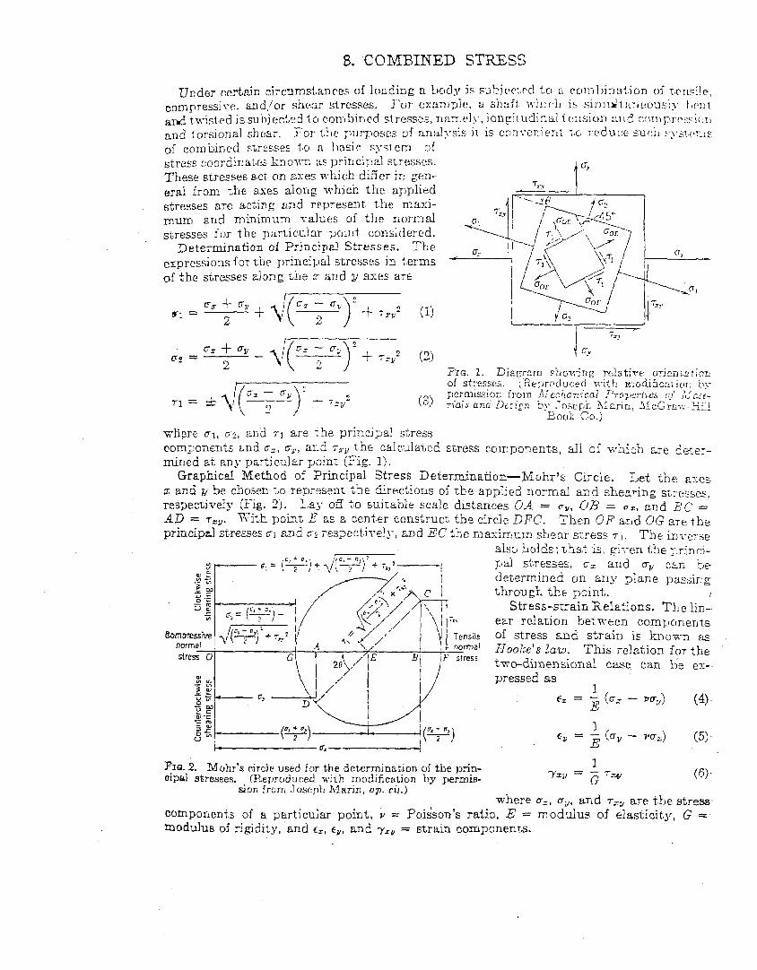
of combincd stresses i,o n I~asic system of stress c:oordinates k3on.n ~s prin ciixil SLXSS~S. These stresses act an axes which difier in gen- eral from the axes along which t h e applied stresses are acting and represent t h e maxi- mum and minimum ~ a l u e s of the normal stresses lor the px-ticular pc~ilit, considercd.
Determination of Principel Stresses. The expressions for tiie priilci1:ial stresses in terms of the stresses along i;Le z s n d y axes are
(3)
7,. 1 G’
stress c.oinporents, all of vhich cre 6p.e:- mined at any particular point (Fig. 1).
Let the ai:es x end y be chosen t o represent t h e Sirections of t,he applied iiormd and shearing stI’e:Sec;, respectively (Fig. 2j. La_\- oE t o sujrable scale distances 0-4 = cy, ClB = o x , and Li’C = AD = T ~ ~ . Ki th point, E zs a center construct the circle DFC. Therl OF a.nd UG are the principal stresses GI 2nd uz respect,ke!y: and EC the nzxinium shear stress 7 - 1 . The iaverse
also holds; t.hstt is, gi-cen tile FriTlcj- pal sh-esses, C T ~ and m,, CLE be determined on any plane pxssing through t h e point. I
Stress-strain Relations. Tile lis-- ear relation fset.rreen components
Tensile of stress and strain is k n o x n SLS
1 Hooke’s law. This relation for the two-dirnensional case can be ex-- pressed as
(4).
( 5 ) .
Yzy = - ( S i ,
Graphicel Method of Principal Stress Determination-Kohr’s Circle.
1 E’ 1 E 1
€s = - (CTZ - PcrI,)
Ey = - cm* - VCTJ
FIQ. 2. Muhr’s circle used for the determination oi the prin- oipal stresses. (Reproduced u i i h modification by permis- G
sion f r o m , J O S ~ J J ~ hlarin, op. ci/.) where u=, cy. and T~~ are the stress.
components of a particular point, Y = Poi$son’s ratio, E = modulus of elasticity, G = modulus of rigidity, and ct, E ~ , and yru = strain components.
- __I__
d 6 4 / Tools a n d Techniques in Failure Analysis
I: was nolcd tha i Eq 1 S is the equxion ora circle uith axes u and T and centered on the u axis \\.lth
and radius, fi, given by:
The result is that stress transformations can be pen-ornied by using the geometric principles of a circle. For example, if stresses are known at a point, they are plotted on a figure that has hori- zontal axis c and vertical axis T so that (ux, ' try)
is the coordinate point at horizontal position 0; and vertical position T~ and so that (uy, T ~ ) is the coordinate that corresponds to ug and T?. Since the center of the circle is on the u a x s , this can be easily found by Eq 16. The radius of the circle is given by Eq 17. From this, the entire circle cnn be drawn. This is illustrated by the schEmatic Mohr's circle in Fig. 5 .
Then for B rotation of axes by 8 in the stress zlzmenr, 012 position on the blohr's circle must go rhrough a romtion of 28 in the same direction bu: around the circumference of the circle. Every point on the circle corresponds Io a possible suess pair. Note that a rotation of 1SO" of the cirde corresponds to a rotation of the stress ele- ment by 90" so hat ux is transformed to ay as shown in Fig. 5.
Principal Stresses. The purpose of a stress transformation is mainly to find the stresses that can be uszd in a failure critxion. These would be either the largest magnitude stresses in any dir-cuon or the magnirude of stresses on a weak plane. For the former, the extreme stresses can be found by talsng Eq 11 and applying the cal- culus principle dt~,,/dB = 0. That is, principal strzsses are normal (perpendicular) stresses on planes for which the shear messes are zero. The values of principal stresses are given by:
where the positive radical eives a maximum stress labeled uI and the negative radical a min- imum stress u2 Notice that the positions of the extreme stresses are the points on the Mohr's circle where the circle crosses the u axis (hori- zontal axis) (Fig. 5 ) .
The right side of the circle corresponds to a maximum normal stress and the left side to a minimum stress. These stresses as called prin- cipal stresses and are often labeled ul and G?.
votice that the extrema] stress given by Eq 18 is :quivalent to taking the center 5 the radius of the Mohr's circle. In this way the extreme values of stresses can be easily found by simply using the Mohr's circle.
The maximum shear stress, T,,,.~, can also be found by taking T~,,,, from Eq 12 and using the calculus principal dszey.ld8 = 0. This results in:
'I, =*/w The value of T , , , ~ is the radius of the Mohr's circle, and the corresponding points on the Mohr's circle are at the top and bottom of the circle as shown in Fig. 5. The maximum shear stress could also be written as:
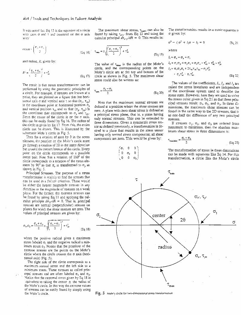
Note that the maximum normal stresses are defined at a position where the shear stresses are zero. A plane with zero shear stress is defined as a principal stress plane, that is, a plane having only normal stresses. This can be extended to three dimensions. Given a symmetric stress ten- sor as defined previously, a transformation is de- sired to a plane that results in the stress tensor having only normal stress components; all shear components are zero. This would be given by:
7
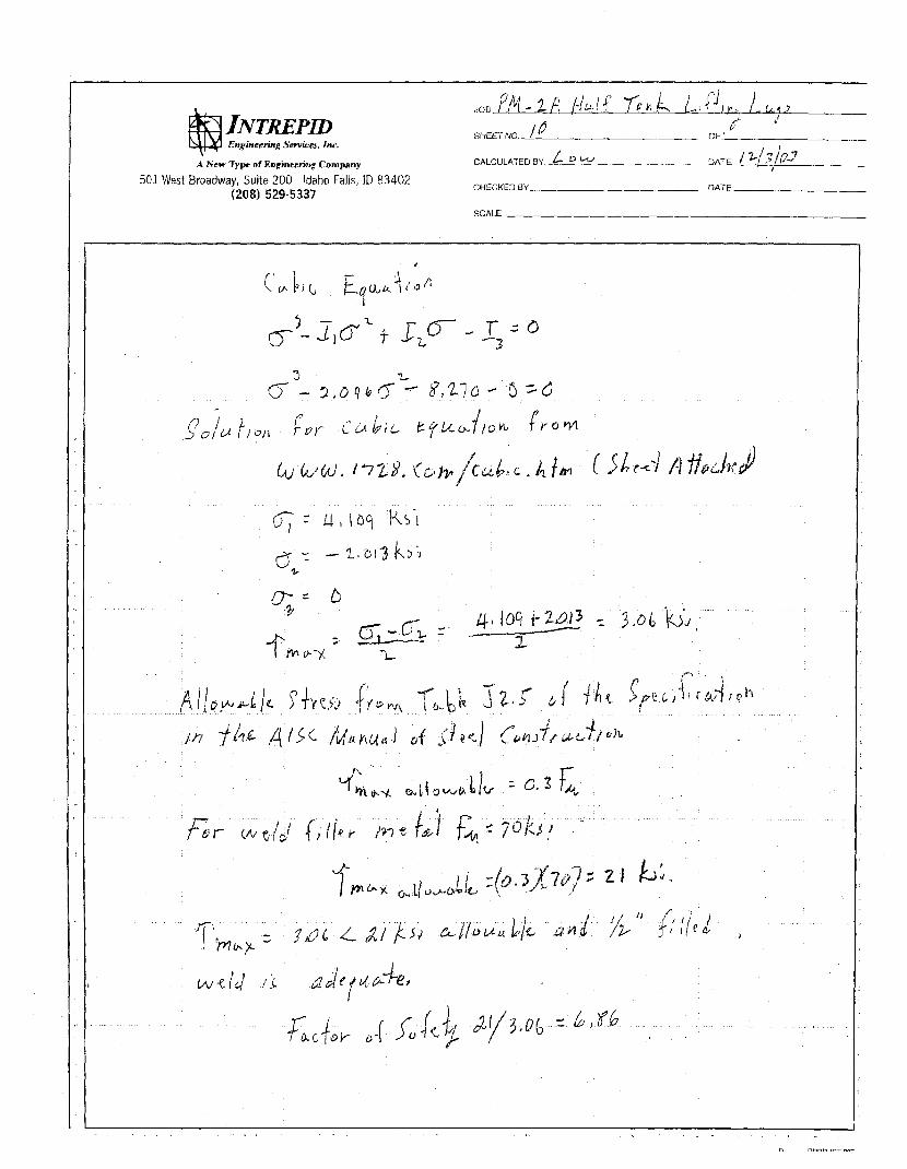
The transformation results in a cubic equation ir u given by:
(Eq 71 4 - 1,s + 1,o - I , = 0
where
I, = 0, + uy + 0,
I2 = U,Uy + UgU, -t U,U, - 7; - T i - T$ 1, = O,O,Cl, + ?TvT=Tx - O,T$
(Eq 27:
The values of the coefficients, I , , 12, and I., are called the stress invariants and are independeni of the coordinate system used to describe t h e stress state. However, here they are used to Solve the stress cubic given in Eq 2 1 so that three prin- cipal stresses result: ol, G?, and t~.,. In three di- mensions, the maximum shear stresses can be found in the same way to the ZD stresses, that is as one-half the difference of any two principal stresses.
If stresses ol, 02, and ci3 are ordered from maximum to minimum, then the absolute m m - imum shear stress in three dimensions is:
-cry.: - o:T;
The transfoxmauon of stress in three dimensions can be made with equations like Eq 14. For this transformation, a circle like the htohr's circle
I J
T n n x
Fig. 5 Mohr's circle for two-dlmensional stress transformation
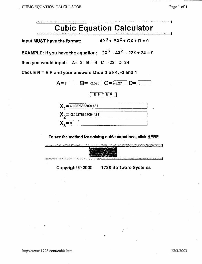
, CUBIC EQUATION CALCULATOR Page 1 of I
Input MUST have the format: AX3 + BX2 + CX + D = 0
EXAMPLE: If you have the equation: 2X3 - 4X2 - 22X + 24 = 0
then you would input: A= 2 B= -4 C= -22 D=24
Click E N T E R and your answers should be 4, -3 and I
I E N T E R I
x = 4.10876853094121
x2=' -2.01 276853094121
__ ..__ .___ 1 - ____
x,= 0 I
To see the method for solving cubic equations, cfick HERE
http://www. 1728.com/cubic.htrn 1 2/3 /2003
096 - 013 EDF- ENGINEERING DESIGN F l l E Rev. No. intrepid technology & resources
i n c o r p o r a t e d
Page 1 of2 EDF Title: PM-2A Half Tank Cover
Project No.: 2000-096 1 Project Title: PM-2A Tanks and Burn Pits RDIRAWP Problem Statement:
4 cover is to be designed for the PM-2A half tank to prevent the debris in the tank from being scattered around .he work site but allow access to the tank to remove the sludge and clean the tank. The access opening is to be 'ive feet wide and allow access for the full width of the tank. The opening is to be designed so that it will move dong the tank to sequentially provide access for removing the sludge and cleaning the tank over the full length of he tank.
Summary of Conclusions:
The designed cover is shown on the attached sketches and on the Drawing, Half Tank Cover, included with the jesign drawings for the project. The design utilizes a 20 mil plastic cover fixed at each end with a cart in betweer Nith reels spaced to provide a 5 feet opening between them. The design is for one reel to wind up the cover from me end of the tank and the other reel to unwind the cover from the other end with the cart and 5 foot space raveling along the tank.
Review and ADDroval Sianatures:
I
Distribution:
Professional Engineer's Stamp (if required)
ENGINEERING DESIGN FILE
EDF Title: PM-2A Half Tank Cover Project No.: 2000-096 Project Title: PM-2A Tanks and Burn Pits RDlRAWP
Problem Statement:
EDF- 096-013 Rev No.: Page 2 of 2
A cover is to be designed for the PM-2A half tank to prevent the debris in the tank from being scattered around the work site but allow access to the tank to remove the sludge and dean the tank. The access opening is to be five feet wide and allow access for the full width of the tank. The opening is to be designed so that it will move along the tank to sequentially provide access for removing the sludge and cleaning the tank over the full length of the tank.
Assumptions:
A 20 mil plastic cover that overlaps the tank sides at least 9 inches will provide adequate containment. The radiation levels will be low enough that personnel will have access to install the cover system and to operate the cover system.
References:
Calculations I Anatysis:
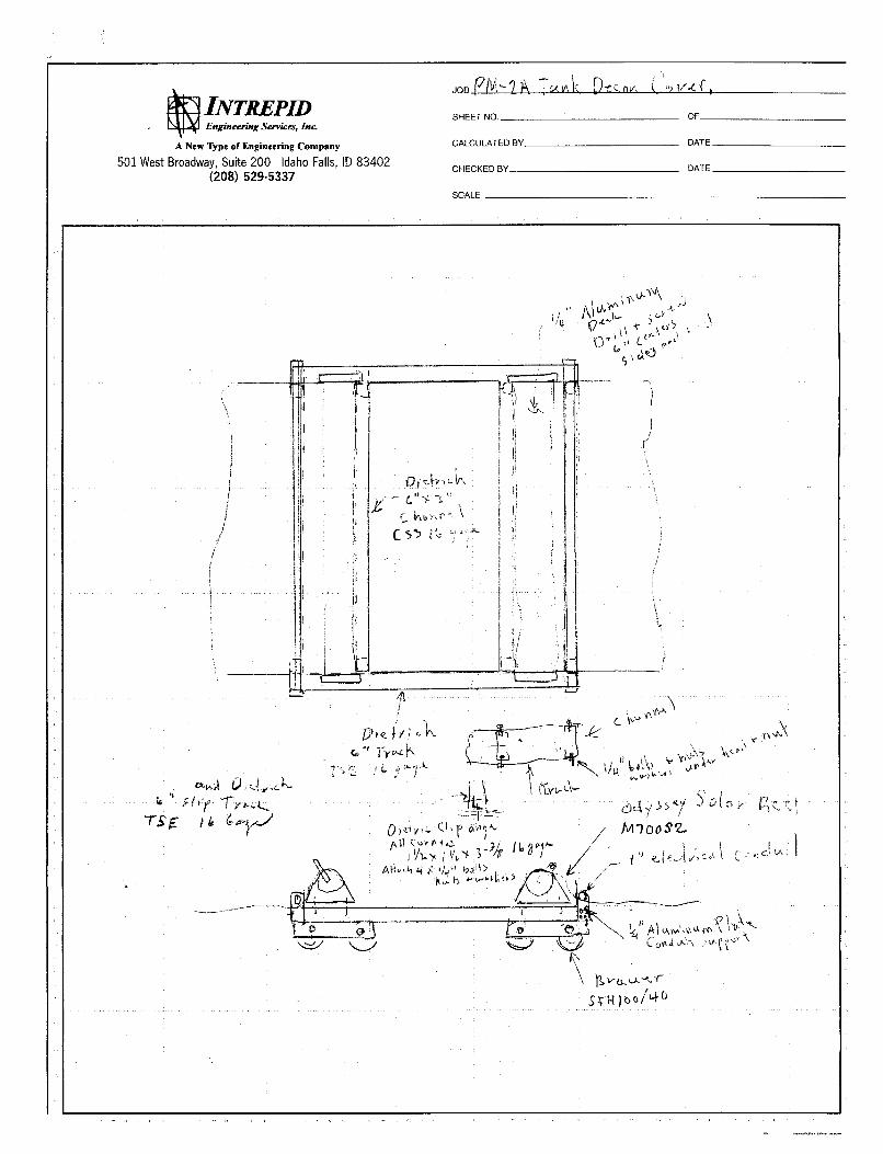
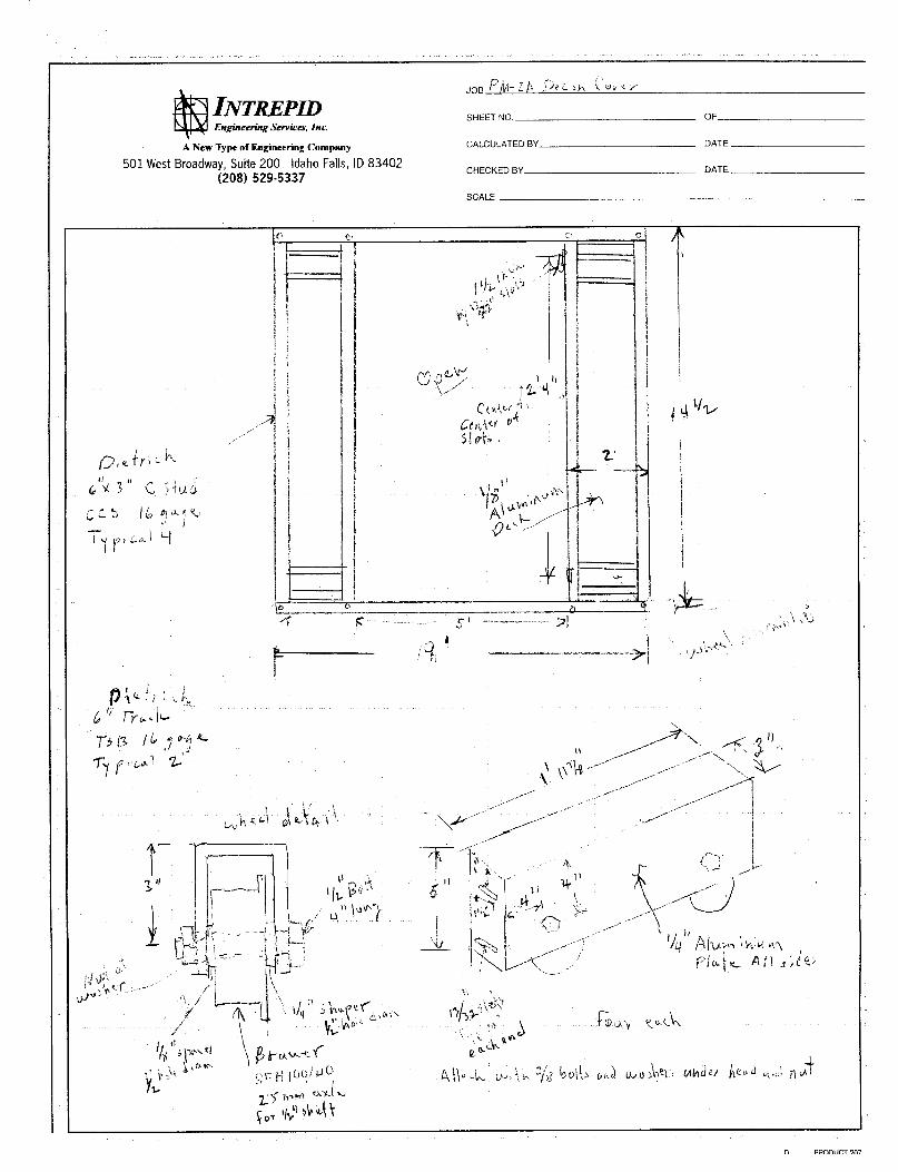
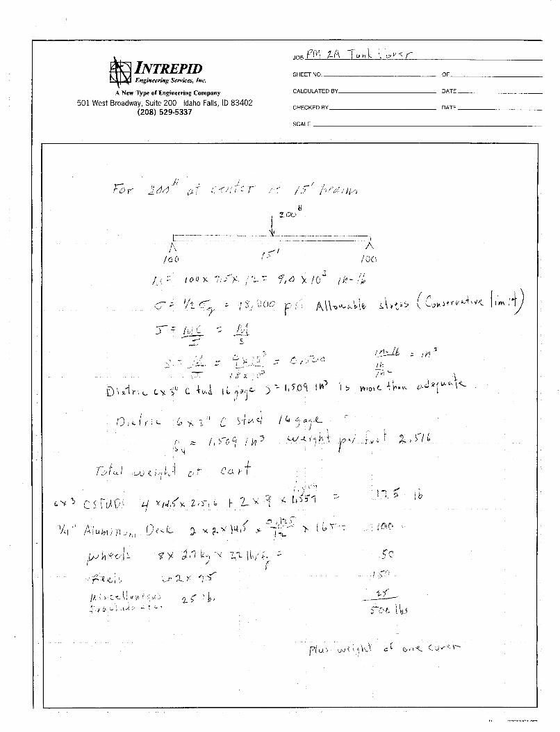
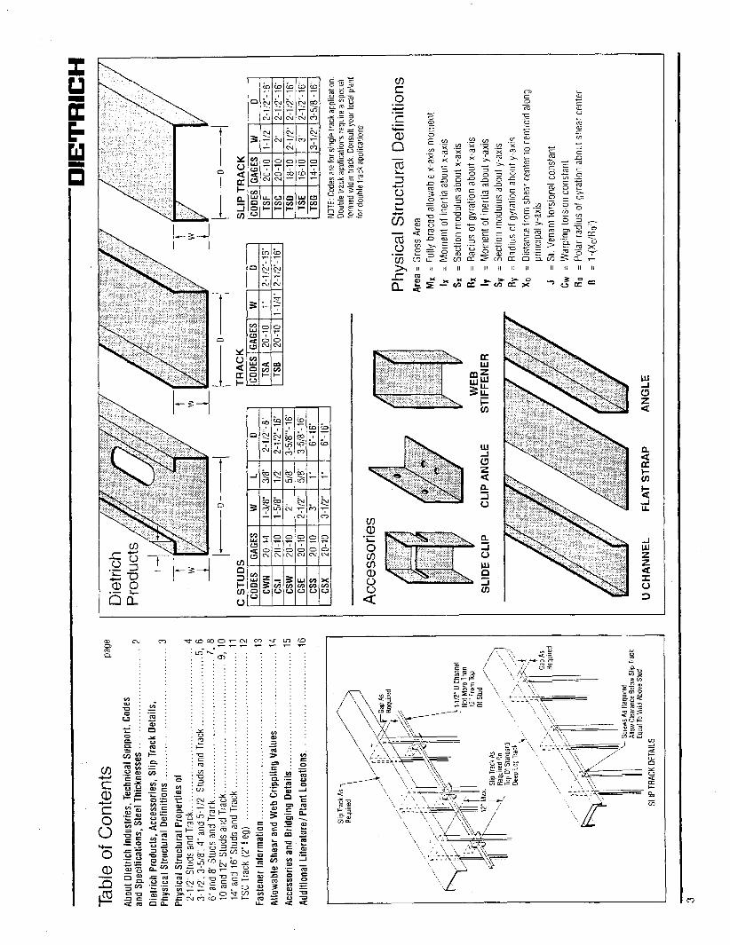
The design utilizes a 20 mil plastic cover fixed at each end with a cart in between with reels spaced to provide a 5 feet opening between them. The design is for one reel to wind up one end of the cover and the other to unwind the other end with the cart and the 5 foot space traveling along the tank. The cart frame is made with 6 inch light weight channels and has two foot wide platforms on each end of the five foot opening. The platforms use a 1/4 inch thick aluminum cover to provide torsional rigidity. The platforms are designed to support a 200 Ib man standing at their centers. Calculations are attached.
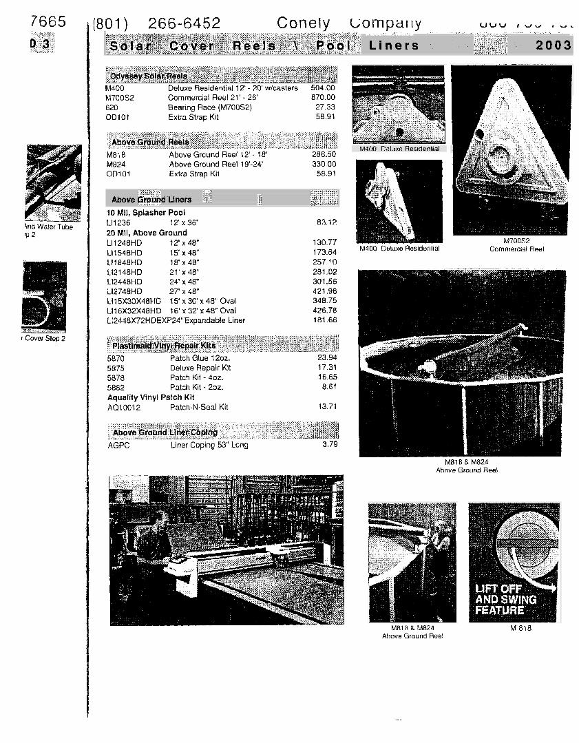
Commercially available swimming pool cover reels are used to wind and unwind the cover. The cart is designed with polyurethane flange wheels that support the cart and roll along the half tank edge. Each corner of the cart has a set of two wheels spaced about 1 foot apart to accommodate any irregularities in the half tank edges. The wheels are flanged on one side and the flanges will be positioned on the outside of the tank to keep the cart correctly positioned over the half tank.
The weight of the cart without the plastic cover is about 500 Ibs with only about 62.5 Ibs per wheel giving confidence that even a deteriorated tank can easily support the cart. Also, the feature of the two closely spaced wheels at each corner allows for one wheel to lose support if the tank has deteriorated and the other wheel to pick up the load. When the first wheel reaches solid support it will carry the load while the second travels over the deteriorated area.
The plastic cover is to be fixed at each end of the half tank. The structure to support and fix the plastic cover at the ends of the tank is shown on EDF 096 - 014.
ATTACHMENTS
Design Sketches Design Calculations Vendor Data

DESIGN SKETCHES
INTREPID Engineering Servica, Ine
A New Type of Engineering Company
(208) 529-5337 501 West Broadway, Suite 200 Idaho Falls, ID 83402
SHEET NO OF
CALCULATED BY DATE
CHECKED BY DATE
SCALE
-_ -- . . - - ---
, a
INTREPID Engineering Sewicrs, Ine
A New Type ofEngineering Company
501 West Broadway, Suite 200 Idaho Falls, ID 83402 (208) 529-5337
- JOB Pb- L ", c I'
SHEET NO OF
CALCULATED BY DATE
DATE CHECKED BY
SCALE
+==== i i i
I
i 1 i I 1
2' -

DESIGN CALCULATIONS
INTREPD Engineerint Services, Inc.
A New Type of Engineering Company
501 West Broadway, Suite 200 Idaho Falls, ID 83402 (208) 529-5337
SHEET NO. OF
CALCULATED BY DATE
CHECKED BY DATE
SCALE

VENDOR DATA
7665
Znd Water Tube 'P 2
r Cover Step 2
(801) 266-6452 uvu I W U n u .
L i n e r s 2 0 0 3
M400 Deluxe Residential 12' - 2 0 wlcasters 504.00 M700S2 Commercial Reel 21' - 26' 870.00 620 Bearing Race (M700S2) 27.33 00101 Extra Strap Kit 58.91
M81B Above Ground Reel 12' - 18' 286.50 M824 Above Ground Reel 19'-24' 330.00 OD101 Extra Strap Kit 58.91
Above d Liners 10 Mil, Splasher Pool LI1236 12' x 36" 20 Mil, Above Ground L11248HD 12' x 48" LI1548HD 15' x 48" 11 1 848 H D 18' x 48" L12148HD 21 x 48" L12448HD 24' x 48" L12748HD 27' x 48" LI15X30X48HD 15' x 30' x 4 8 Oval L116X32X48HD 16' x 32' x 48" Oval L12448X72HDEXP24' Expandable Liner
83.12
1 30.77 173.64 257.10 281.02 301.56 421.96
426.78 181.66
348.75
M400 CalJxe Residential
M400 Deluxe Residential Commercial Reel
5870 Patch Glue 1202. 5875 Deluxe Repair Kit 5878 Patch Kii - 402. 5882 Patch Kit - 202. Aquality Vinyl Patch Kit AQ10012 Patch-N-Seal Kit
23.94 17.31 16.65 8.61
13.71
AGPC Liner Coping 5 3 Long 3.79
M818 & MB24 Above Ground Reel
M818 B M824 Above Ground Reel
M 818
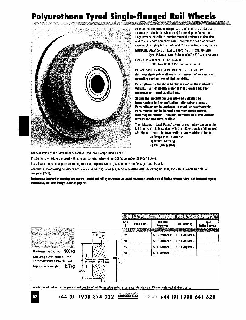
Standard wheel features flanges with a 5' angle and a 'flat tread' (ie tread parallel to the wheel axis) for running on flat top rail. Polyurethane is resilient, durable material, resistant to abrasion and to many common chemicals. Polyurethane tyred wheels are capable of carrying heavy loads and of transmitting driving forces MATERIAL wheel GenW - Steel to 85970 Part 1 1983.080 M40
OPERATING TEMPERATURE RANGE: -20% to t 60C (1 15'C for limited use)
PLEASE SPECIFY IF OPERATING IN HIGH HUMIDITY. Anli-hydrolysis polyurethane is recommended for use in an operating environment of high humidfty.
Polyurslhane lo the above hardness used on these wheels is Vulkollan, a high qualtly malerial lhai provides superior pertonnance in mosl applications.
Should the mechanical properties of Vulkollan be inappropriate for the application, anernalive grades of Polyurslhane can be produced to meet the rsquiremenls. Polyurelhane can be bonded onlo mosl meial centres including aluminium, lilanium, stainless sleel and various ferrous and non-f#rous alloys.
The Maximum Load Rating' given for each wheel assumes the full tread width is in contact with the rail. In practice full contact with the rail across the tread width is rarely achieved due to:-
Tyre - Polyester Based Polymer of 92' + 3' A Shore Hardness
a) Flange to rail clearance b) Wheel Overhang c) Rail Comer Radii
For calculation of the 'Maximum Allowable Load' see 'Design Data' Para 6.1 In addition the 'Maximum Load Ratlng' given for each wheel is for aperatton under ideal conditions. Load factors must be applied according to the anticipated working conditions - see 'Design Data' Para 4.1 Alternative BDre/Beafing diameters and alternative bearing types (is) bronze brushes. self lubticating brushes, etc.) em available to brder - see pa@ 17-1 8. For lecbnical infomstlea cweriau bad Worn, inedkl and mlllng mirhucs, chembl roslstanm, w)eIRhjeaL of Mdien Bstrrscl WkMl and W a n d Lsv#v dimensions, see 'Dala Design' Index on page 12.
See 'Design Data' paras 4.1 and 6.1 for'Maximurn Allowable Load'.
Approximate weight 2.7kg
U 1 I W k l s f i vath ball journals are pre-lubricated, double shielded Akernziwely greaslng can be through the axle- slate if this option is required when ordenng
+44 (0) 1908 374 022 +44 (0) 1908 641 628
\ I-3-4
I
. . . . . . . . .
'!-
u w ln u
Y 0 a .L
Hotspring" -*m Fudk S F -**
* Tiger River Portads Spas - Hot Saot Anywhere Anytime Tub * Conneily Blliard Tables - Billiard b Dart Accessories * Viking Pools . bnnieo Sauna and Steam Aooms . a,o Guard Water Care Products . Son S m Water Care Poducts
Spa b Pool Accessories hee Water Rnalvsls
EDF- 096 -14 ENGINEERING DESIGN FILE Rev. No. intrepid technology & resources
i n c o r p o r a t e d
Panel o f ? . - - . - . - EDF Title: PM-2A Half Tank Positive Air Flow System
Project No.: 2000-096 1 Project Title: PM-2A Tanks and Burn Pits RDIRAWP
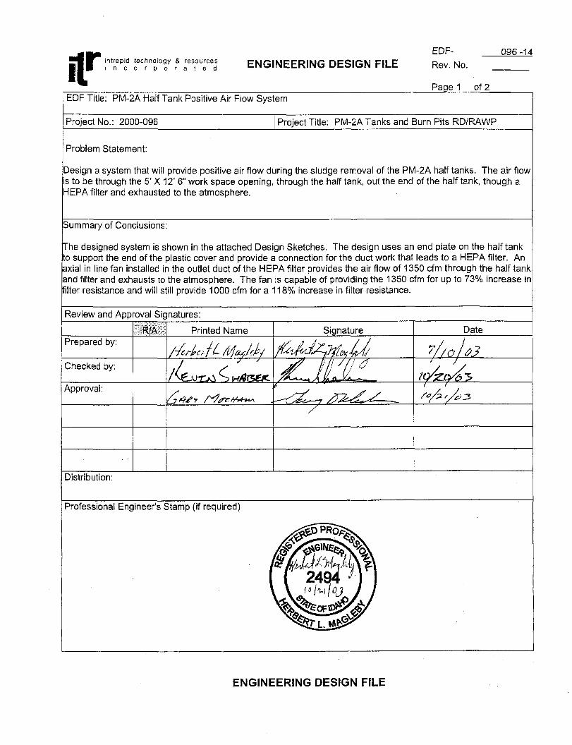
Problem Statement:
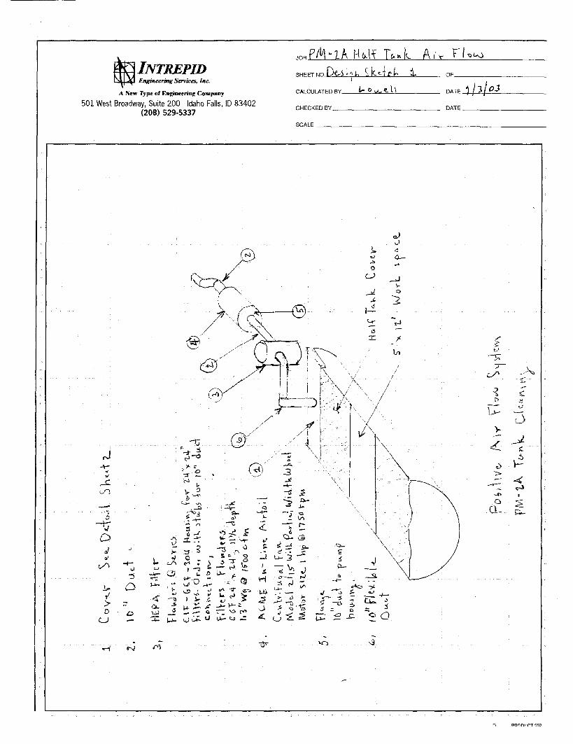
Iesign a system that will provide positive air flow during the sludge removal of the PM-2A half tanks. The air flow j to be through the 5’ X 12’ 6” work space opening, through the half tank, out the end of the half tank, though a {EPA filter and exhausted to the atmosphere.
hmmary of Conclusions:
‘he designed system is shown in the attached Design Sketches. The design uses an end plate on the half tank 3 support the end of the plastic cover and provide a connection for the duct work that leads to a HEPA filter. An ixial in line fan installed in the outlet duct of the HEPA filter provides the air flow of 1350 cfm through the half tank ind filter and exhausts to the atmosphere. The fan is capable of providing the 1350 cfm for up to 73% increase ir Iter resistance and will still provide 1000 cfm for a 11 8% increase in filter resistance.
?eview and Awroval Signatures:
~~
listribution:
’rofessional Engineer’s Stamp (if required)
ENGINEERING DESIGN FILE
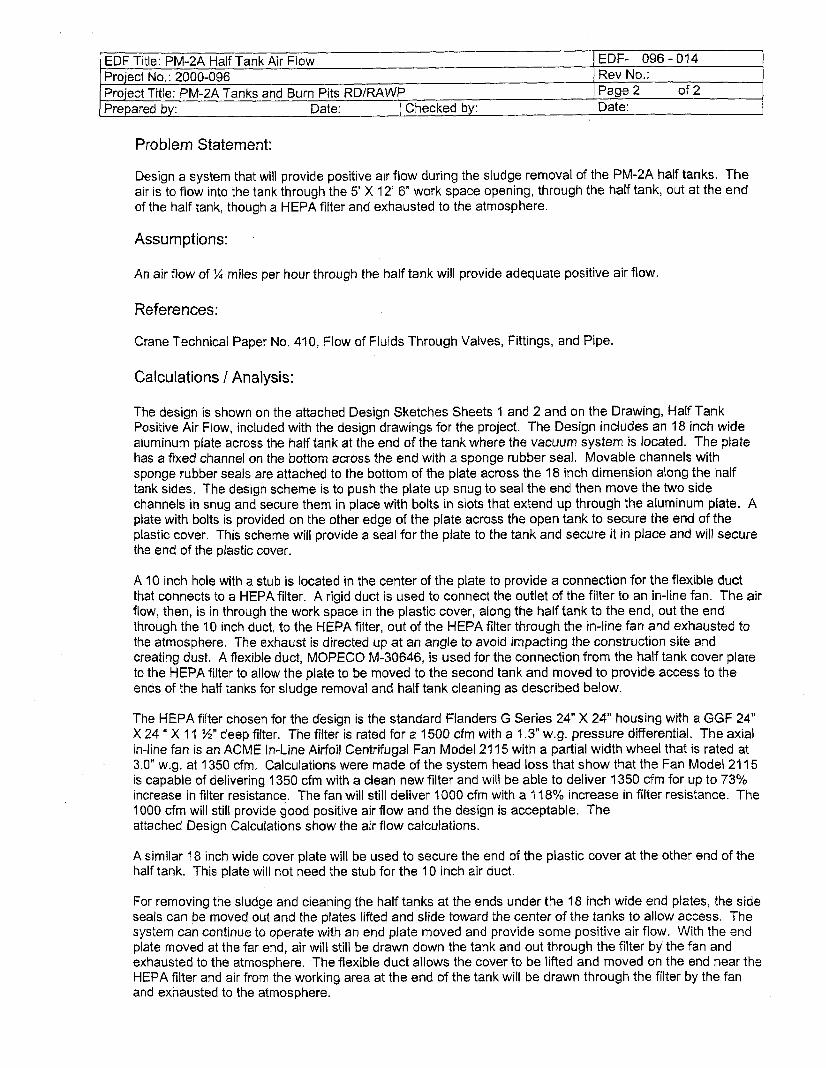
1 EDF Title: PM-2A Half Tank Air Flow Project No.: 2000-096 Project Title: PM-2A Tanks and Burn Pits RDIRAWP
Problem Statement:
EDF- 096-014 Rev No.: Page 2 of 2
Design a system that will provide positive air flow during the sludge removal of the PM-2A half tanks. The air is to flow into the tank through the 5’ X 12’ 6” work space opening, through the half tank, out at the end of the half tank, though a HEPA filter and exhausted to the atmosphere.
Assumptions:
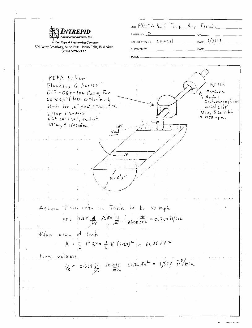
An air flow of % miles per hour through the half tank will provide adequate positive air flow.
References :
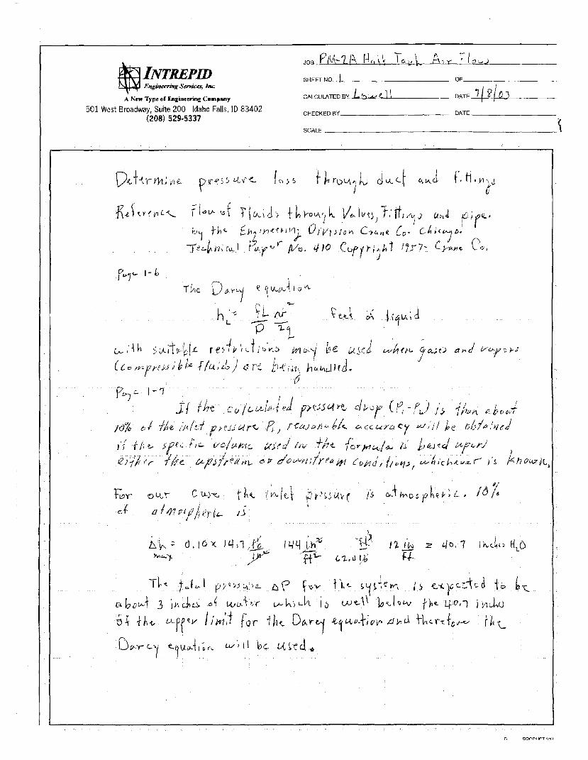
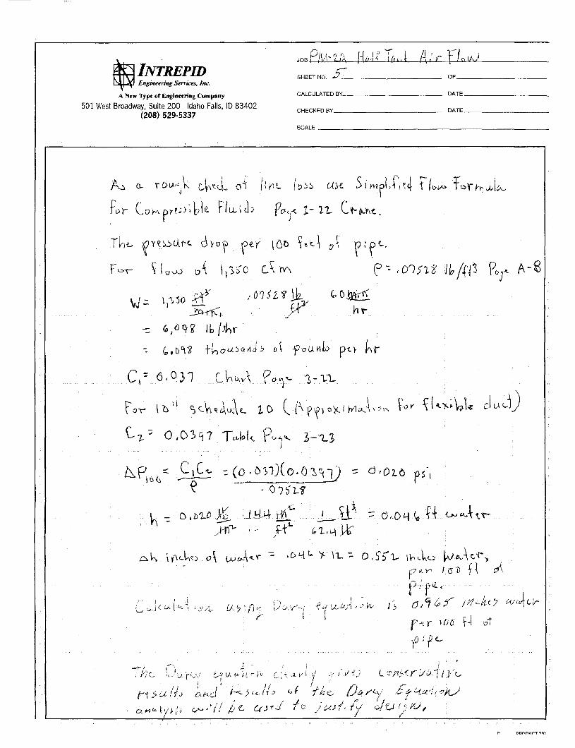
Crane Technical Paper No. 410, Flow of Fluids Through Valves, Fittings, and Pipe.
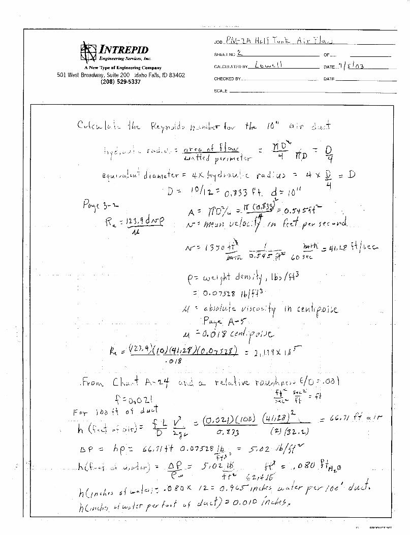
Calculations / Analysis:
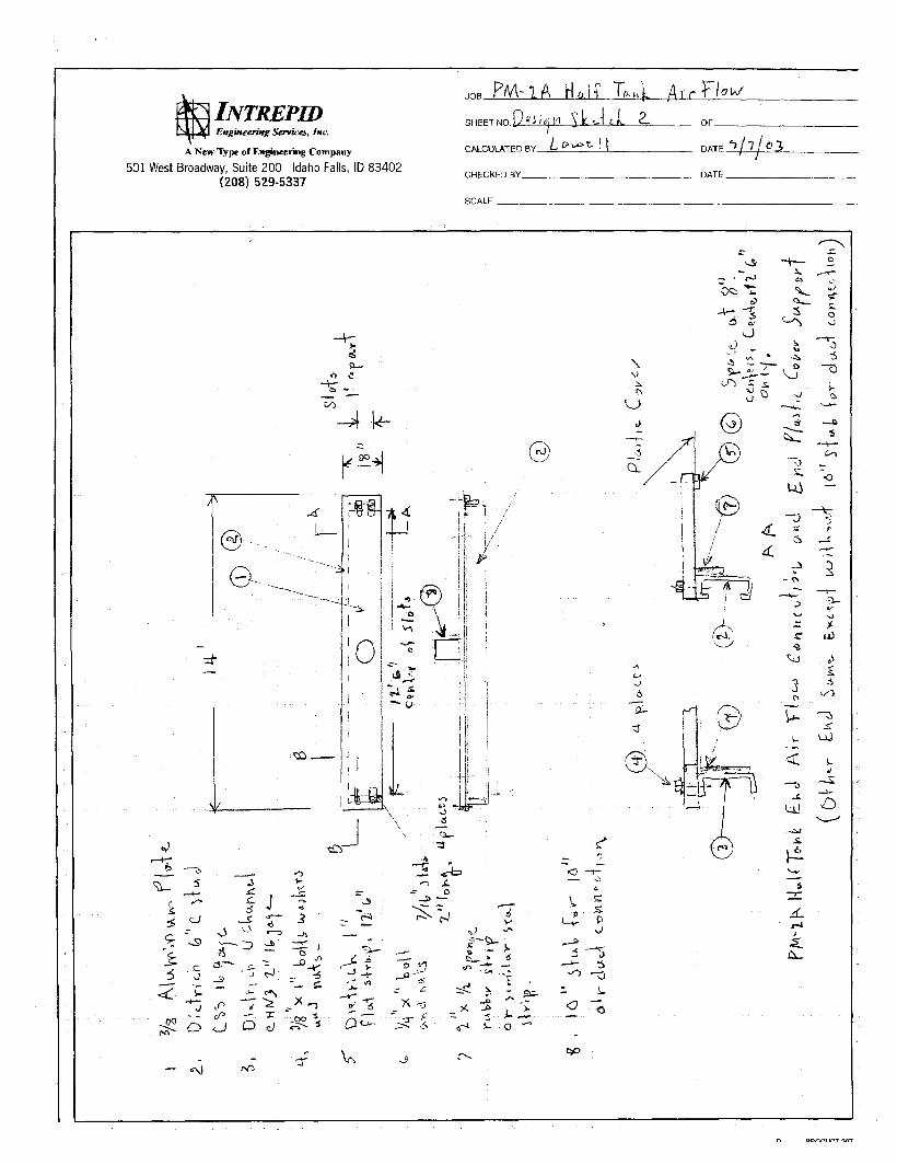
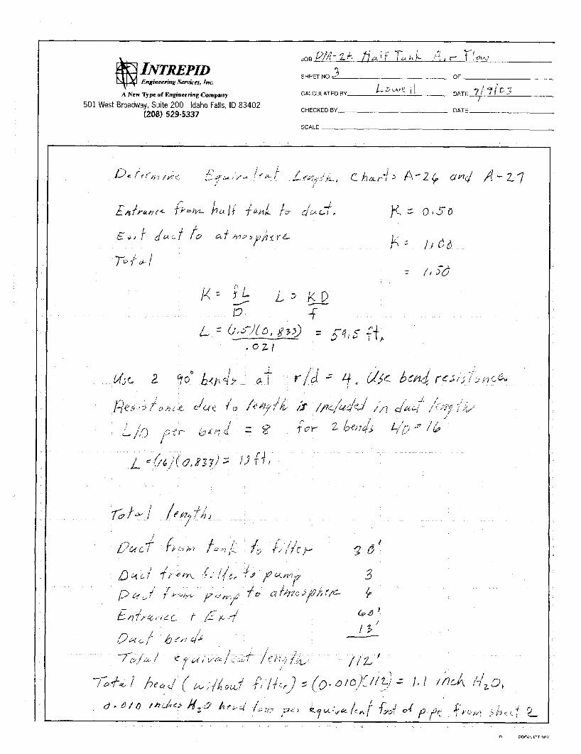
The design is shown on the attached Design Sketches Sheets I and 2 and on the Drawing, Half Tank Positive Air Flow, included with the design drawings for the project. The Design includes an 18 inch wide aluminum plate across the half tank at the end of the tank where the vacuum system is located. The plate has a fixed channel on the bottom across the end with a sponge rubber seal. Movable channels with sponge rubber seals are attached to the bottom of the plate across the 18 inch dimension along the half tank sides. The design scheme is to push the plate up snug to seal the end then move the two side channels in snug and secure them in place with bolts in slots that extend up through the aluminum plate. A plate with bolts is provided on the other edge of the plate across the open tank to secure the end of the plastic cover. This scheme will provide a seal for the plate to the tank and secure it in place and will secure the end of the plastic cover.
A 10 inch hole with a stub is located in the center of the plate to provide a connection for the flexible duct that connects to a HEPAfilter. A rigid duct is used to connect the outlet of the filter to an in-line fan. The air flow, then, is in through the work space in the plastic cover, along the half tank to the end, out the end through the 10 inch duct, to the HEPA filter, out of the HEPA filter through the in-line fan and exhausted to the atmosphere. The exhaust is directed up at an angle to avoid impacting the construction site and creating dust. A flexible duct, MOPECO M-30646, is used for the connection from the half tank cover plate to the HEPA filter to allow the plate to be moved to the second tank and moved to provide access to the ends of the half tanks for sludge removal and half tank cleaning as described below.
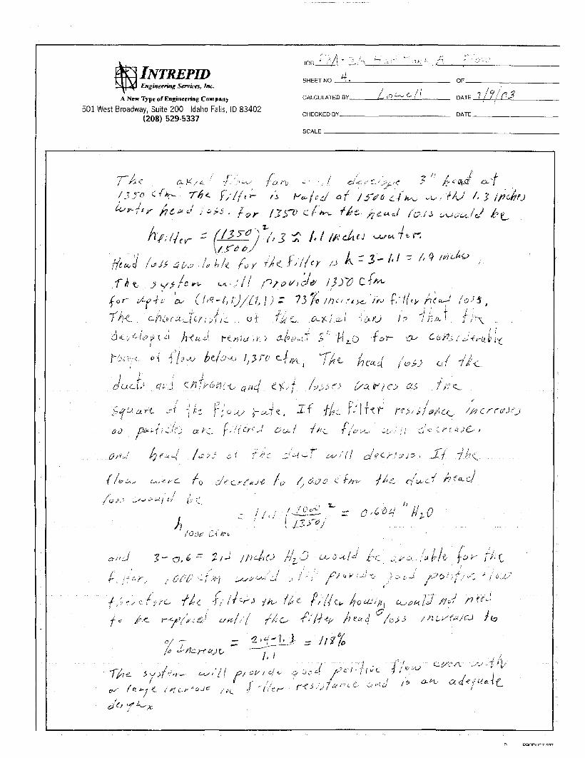
The HEPA filter chosen for the design is the standard Flanders G Series 24” X 24” housing with a GGF 24” X 24 “ X 11 X’’ deep filter. The filter is rated for a 1500 cfrn with a I .3” w.g. pressure differential. The axial in-line fan is an ACME In-line Airfoil Centrifugal Fan Model 21 15 with a partial width wheel that is rated at 3.0” w.g. at 1350 cfm, Calculations were made of the system head loss that show that the Fan Model 21 15 is capable of delivering 1350 cfm with a clean new filter and will be able to deliver 1350 cfm for up to 73% increase in filter resistance, The fan will still deliver 1000 cfrn with a 1 7 8% increase in filter resistance. The 1000 cfm will still provide good positive air flow and the design is acceptable. The attached Design Calculations show the air flow calculations.
A similar 18 inch wide cover plate will be used to secure the end of the plastic cover at the other end of the half tank. This plate will not need the stub for the I O inch air duct.
For removing the sludge and cleaning the half tanks at the ends under the 18 inch wide end plates, the side seals can be moved out and the plates lifted and slide toward the center of the tanks to allow access. The system can continue to operate with an end plate moved and provide some positive air flow. With the end plate moved at the far end, air will still be drawn down the tank and out through the filter by the fan and exhausted to the atmosphere. The flexible duct allows the cover to be lifted and moved on the end near the HEPA filter and air from the working area at the end of the tank will be drawn through the filter by the fan and exhausted to the atmosphere.

DESIGN SCKETCHES
*--
JOB f/lZ.zA Hklf T & H A A i , b LL3 ? INTREPID S H E E T N O ~ J G S ~ * ~ ~ Z k t i r k OF
Engmeering Semifa, Inc.
A New Type of Engineering Conpany CALCULATED BY I, Lb 1 \ DATE ! 3 j 0 3
CHECKED BY DATE (208) 529-5337
501 West Broadway, Suite 200 Idaho Falls, ID 83402
SCALE
J
rl
-- A A - 5 .
JOB Pa-? A H & , i T &-ilk A ) r s H E E T N o p ~ > i t i ~ l 1 kLLt ,IL Z CALCULATED BY L 1 DATE $/7j03 CHECKED BY DATE
OF Engmeering Services, Inc.
A New Type of Engineering Company
(208) 529-5337 501 West Broadway, Suite 200 Idaho Falls, ID 83402
0)
-% d a
I I a-
%- 3
P
- 5 5 - 3
- 7 3
h
cu 4 n

DESIGN CALCULATIONS
A New Type o f Engineering Compnny
501 West Broadway, Suite 200 Idaho Falls, ID 83402 (208) 529-5337
u
SCALE
A New Type of Engineering Compnny
CHECKED BY DATE 501 West Broadway, Suite 200 Idaho Falls, ID 83402
c (208) 529-5337 SCALE I
-4 *- JOB P/M,-~ /+ I-I,+I 1 u i l \ ~ s% . r 7 /a,,,J
INTREPID SHEETNO 2 OF Engineering Serviea, Inc
A New Type of Engineering Company CALCULATED BY /- h kc- 1 1 DATE '1 I 6 0 3
CHECKED BY DATE 501 West Broadway, Suite 200 Idaho Falls, ID 83402
(208) 529-5337 SCALE
A New Type of Engineering Company
--t
SHEET ~ o . 2 OF
CHECKED BY DATE 501 West Broadway, Suite 200 Idaho Fails, ID 83402
(208) 529-5337 SCALE
13 f
JOB
INTMPID SHEETNO 4. OF- Enguterring Servua, Jnc
A New Type of Engineering Company CALCULATED BY / D L C / / DATE ? /? p J
CHECKED BY DATE (208) 529-5337 501 West Broadway, Suite 200 Idaho Falls, ID 83402
SCALE
SHEET NO 5- OF
A New Typ of Engineering Company CALCULATED BY DATE
CHECKED BY DATE 501 West Broadway, Suite 200 Idaho Falls, ID 83402 (208) 529-5337
SCALE
CRANE FLOW OF FLUIDS EQUATIONS AND CHARTS
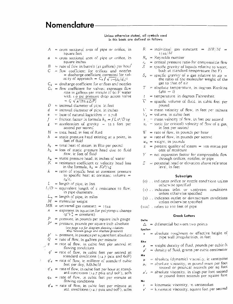
Nomenclature
A =
a =
B = c =
D = d = e =
g =
H = h =
h, = h, =
h, = I< =
k =
f =
L = L I D =
L , = M = MR =
n =
P = p’ =
Unless otherwise stated, all symbols used in this book are defined as follows:
cross sectional area of pipe or orifice, in
cross sectional area of pipe or orifice, in
rate of flo\i. in barrels (4; gallons) per h o d flow coefficient for orifices and nozzles
= discharge coefficient corrected for vel- ocity of approach = C, / ,/ \-(do/dl)4
discharge coefficient for orifices and nozzles flow coefficient for i,.alves: expresses flow
rate in gallons per minute of So F water n.ith 1 . 0 psi pressure clrop across valve = Q >‘ pI(62.4AP)
square feet
square inches
internal diameter of pipe, in feet internal diameter of pipe, in inches base of natural logarithm = 2.718 friction factor in formula h , = f L G / D zg acceleration of gravity = 3 2 . 2 feet pei-
total head, in feet of fluid static pressure head existing a t a point, in
totai heat of steam, in Btu per pound loss of static pressure head clue to fluid
static pressure heacl, in inches of water resistance coefficient or velocity head loss
in the formula, h , = Kvz/2g ratio of specific heat a t constani pressure
to specific heat at constant volume = c,/c a
second per second
feet of fluid
flow, in feet of fluid
length of pipe, in feet equivalent length of a resistance to flow.,
in pipe diameters length of pipe, in miles molecular weight universal gas constant = I 544 exponent in equation for polytropic change
pressure, in pounds per square inch gauge pressure, pounds per square inch absolute
(see page 1-5 for diagram showing relalion- ship between gauge and absolute pressure)
(b’b”: = constant)
pressure, in pounds per square foot absolute rate of flow, in gallons per minute rate of flow. in cubic feet per second a t
flowing conditions rate of flow, in cubic feet per second at
standard conditions ( I 4.7 psia and 60F) rate of flow, in millions of standard cubic
feet per day, M ~ l s c f d rate of flow, in cubic feet per hour a t stand-
ard conditions (14.7 p i a and boF), scfh rate of flow, in cubic feet per minute at
flowing conditions rate of flow, in cubic feet per minute a t
std. conditions ( 1 4 . 7 psia and boFj, scfm
individua! gas constant = iLIi<,’!bl =
Reynolds number critical pressure ratio for compressible flow specific gravitl- of liquids relative to Lvacer,
both a t standard temperature (60 Fj specific gravity of a gas relative to air =
the ratio of the molecular weight of the gas to that of air
absolute temperature, in degrees Rankine (463 + t )
temperature, in degrees Fahrenheit specific volume of fluid. in cubic feet per
mean velocity of flow, in feet per- minute volume, in cubic feet mean velocity of flow, in feet per second sonic (or critical) \.elocity of flon. of a gas,
rate of floa, in pounds per hour rate of floxv, in pounds per second \\-eight, in pounds percent quality of steam = loo minus per
net expansion factor for compressible flow-
porential head or elevation above reference
I j44//Ll
pound
in feet per second
cent of moisture
through orifices, nozzles. or pipe
level, in feer:
Subscripts indicates orifice or nozzle conditions unless
indicates inlet or upstream conditions
indicates outlet or donmstream conditions
refers to 130 feet of pipe
other \v ise specified
unless othera,ise specified
unless othernise specified
Greek Letters
dtfterential betn.een tlvo points
alxolute roughness or effective height of Fipe -.all irregularities, in feet
weight density of fluid, pounds per cubic f t density of fluid, grams per cubic centimeter
al-solute (dynamicj viscosity, in centipoise absolute viscosity, in pound r a s s per foot
xcond or poundal seconds per sq foot absolute viscosity, in slugs per foot second
or pound force seconds per square foot
kinematic viscosity. in centistokes kinematic viscosity, square feet pel. second
1 - 6 CHAPTER 1 - T H E O R Y OF FLOW IN P I P E C R A N E
Darcy's Formula General Equation for Flow of Fluids
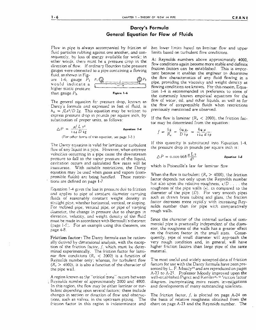
Flow in pipe is always accompanied by friction of fluid particles rubbing against one another, and con- sequently, by loss of energy available for work; in other words, there must be a pressure drop in the direction of flow. I f ordinary Bourdon tube pressure gauges were connected to a pipe containing a flowing fluid, as shown in Fig-
wou ld i n d i c a t e a I. * Q ure 1-6, gauge PI PI 9 L q) r P2
higher static pressure " J
than gauge P z . Figure 1-6
The general equation for pressure drop, known as- Darcy's formula and expressed in feet of fluid, is h , = fLv2,'/D 2g. This equation may be written to express pressure drop in pounds per square inch, by substitution of proper units, as follows:
(For other forms of this equation, see page 3-2.)
The Darcy equation is valid for laminar or turbulent flow of any liquid in a pipe. However, when extreme velocities occurring in a pipe cause the downstream pressure to fall to the vapor pressure of the Iiquid, cavitation occurs and calculated flow rates will be inaccurate. With suitable restrictions, the Darcy equation may be used when gases and vapors (com- pressible fluids) are being handled. These restric- tions are defined on page 1-7.
Equation 1-4 gives the loss in pressure due to friction and applies to pipe of constant diameter carrying fluids of reasonably constant weight density in straight pipe, whether horizontal, vertical, or sloping. For inclined pipe, vertical pipe, or pipe of varying diameter, the change in pressure due to changes in elevation, velocity, and weight density of the fluid must be made in accordance with Bernoulli's theorem (page 1-5). For an example using this theorem, see page 4-3.
Friction factor: The Darcy formula can be ration- ally derived by dimensional analysis, with the excep- tion of the friction factor, I, which must be deter- mined experimentally. The friction factor for lami- nar flow conditions (Re < 2000) is a function of Reynolds number only; whereas, for turbulent flow ( R e > 4OOOj , it is also a function of the character of the pipe wall.
A region known as the "critical zone" occurs between . Reynolds number of approximately 2000 and 4000.
In this region, the flow may be either laminar or tur- bulent depending upon several factors ; these include changes in section or direction of flow and obstruc- tions, such as valves, in the upstream piping. The friction factor in this region is indeterminate and
'
has lower limits based on laminar Bow and upper limits based on turbulent flow conditions.
At Reynolds numbers above approximately 4000, flow conditions again become more stable and definite friction factors can be established. This is impor- tant because it enables the engineer to determine the flow characteristics of any fluid flowing in a pipe, providing the viscosity and weight density a t flowing conditions are known. For this reason, Equa- tion 1-4 is recommended in preference to some of the commonly known empirical equations for the flow of water, oil, and other liquids, as well as for the flow of compressible fluids when restrictions previously mentioned are observed.
If the flow is laminar (Re < ZOOO), the friction fac- tor may be determined from the equation:
/=-=L=--- 64 6 4 ~ 64 P Re D up 123 d u p
I f this quantity is substituted into Equation 1-4, the pressure drop in pounds per square inch is:
p L 2,
d? Equation 1-5 A P = 0.000 668 -
which is Poiseuille's law for laminar flow.
When the flow is turbulent (Re > 4000), the friction factor depends not only upon the Reynolds number but also upon the relative roughness, e,/D . . . . the roughness of the pipe walls (E), as compared to the diameter of the pipe (D). For very smooth pipes such as drawn brass tubing and glass, the friction factor decreases more rapidly with increasing Rey- nolds number than for pipe with comparatively rough walls.
Since the character of the internal surface of com- mercial pipe is practically independent of the diam- eter, the roughness of the walls has a greater effect on the friction factor in the small sizes. Conse- quently, pipe of small diameter will approach the very rough condition and, in general, will have higher friction factors than large pipe of the same material.
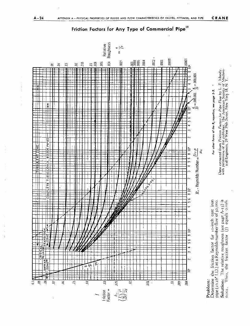
The most useful and widely accepted data of friction factors for use with the Darcy formula have been pre- sented by L. F. I v l ~ o d y ' ~ and are reproduced on pages A-23 to A-25. Professor Moody improved upon the well-established Pigott and Kemler'% friction factor diagram, incorporating more recent investigations and developments of many outstanding scientists.
The friction factor, f, is plotted on page A-24 on the basis of relative roughness obtained from the chart on page A-27 and the Reynolds number. The
c R A N E APPENDIX A - PHYSICAL PROPERTIES OF FLUIDS AND FLOW CHARACTERISTICS OF VALVES, FITTINGS, A N D PIPE A - 5
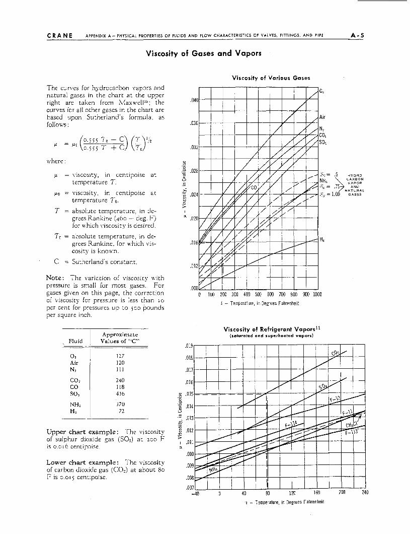
Viscosity of Gases and Vapors
Viscosity of Various Gases
The curves for hydrocarbon vapors and natural gases in the chart a t the upper right are taken from M a x ~ ~ ~ e l l l ~ ; the curves for all other gases in the chart are based upon Sutherland's formula, as f 0 l l O i l ~ S :
where
p = viscosity, in centipoise a t temperature T.
PO = viscosity, in centipoise a t temperature To.
T = absolute temperature, in de- grees Rankine (460 - deg. F) for which viscosity is desired.
TO = absolute temperature, in de- grees Rankine, for urhich vis- cosity is knoivn.
C = Sutherland's constant,
Note: The variation of \viscosity \\.ith pressure is small for most gases. For gases giipen on this page, the correction of viscosity for pressure is less than 10
per cent for pressures up to joo pounds per square inch.
~ Fluid
0 2
Air N? co: co so2 NHs HI
Approximate Values of "C"
127 120 1 1 1
240 118 416
3 70 72
Upper chart example : The viscosity of sulphur dioxide gas (SO?) at zoo F is 0.01 6 centipoise.
Lower chart example : The viscosity of carbon dioxide gas (CO?) a t about 80 F is 0.015 centipoise.
o loo 200 300 400 500 600 700 800 900 ioao 1 - Temperature, in Degrees Fahrenheit
Viscosity of Refrigerant Vapors1I (sa tura ted and s u p e r h e a t e d v a p o r s )
.5 H Y D R O C A R B O N V A P O R .$ A N D
N A T U R A L ..ob G A S E S
1 - Temperature, In Degrees Fahrenheit
A - 8 APPENDIX A-PHYSICAL PROPERTIES OF FLUIDS AND FLOW CHARACTERISTICS OF VALVES. FITTINGS. AND PIPE c R A N E
Indi- vidual
Gas :onstant
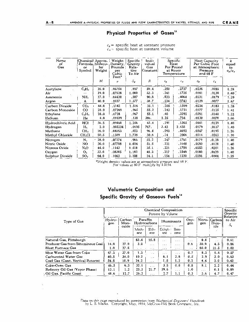
Physical Properties of Gases1'
Specific Heat
Per Pound a t Room
Tempera tu re
c,= specific heat a t constant pressure c = specific heat a t constant volume
59.4 53.3 90.8 38.7
.350 -2737
.241 .1725
.523 .4064
.124 .0743
Acetylene Air Ammonia Argon Carbon Dioxide Carbon Monoxide Ethylene He l ium Hydrochloric Acid Hydrogen Methane Methyl Chloride Nitrogen Nitric Oxide Nitrous Oxide Oxygen Su lphur Dioxide
C,H?
"3
A coz CO
GHI He
HCl H1
CH 4
CH,C1 N? NO N?O 0 2
SO2
-
35.1 .205 55.2 .243 55.1 -40
386. 1.25
.1599
.1721
.3292
.754 42.4 .I91
767. 3.42 96.4 ,593 30.6 .24
.1365
.4692
.2006
2.435
55.2 .247 .231 .221
48.3 .217 24.1 [ .154
.I761
.1648
.1759
.1549
.1230
- :arbon Diox-
ide
Specific Gravity Relative t o Air
so
~
Approx. Molecu-
la r Weight
M
Weight Density, Pounds
Pe': Cubic Foot'
P
Specific Gravity Rela- tive
To Air
s*
1Chemica
Symbol
zr of IForr-rult Heat Capacity Per Cubic Foot a t Atmospheric
Pressure a n d 68 F
I
k equal to
CPlCO
1.28 1 ;40- 1-.29 1.67 1.28 1.41 1.22 1.66 1.40 1.40 1.26 1.20 1.40 1.40 1.26 1.40 1.25
c,
.0236
.0181
.0231
.0129
26.0 29.0 17.0 40.0
.06754
.07528
.04420
. lo37
.897 1.000
.587 1.377
.0185
.0130
.0179
.0077
.0183
.0125
.0240
.0078
44.0 28.0 28.0
4.0
.1142
.07269
.0728
. 0 1039
1.516 .965 .967 .138
.0234
.0177
.0291
.0130 36.5
2.0 16.0 50.5
.09460
.005234
.04163
.1309
1.256 .0695 .553
1.738
.0181
.0179
.0247
.0314
.0129 ,0127 ,0195 .0263 .0128 -0128 .0201 .0129 .0204
.966 1.034 1.518 1.103 2.208
.0179
.0180
.OX3
.om0 ,0256
' 28.0 30.0 44.0 32.0 64.0
.07274
.07788
.1143
.OS305
.1663
*Weight density values'are a t atmospheric pressure and 68 F For values a t 60 F, multiply by 1.0154.
Volumetric Composition and Specific Gravity of Gaseous Fuelsi3
Chemical Composition Percent by Volume
Type of Gas Oxy- Nitro- gen 1 gen
Carbon Mon- oxide
Meth- Eth- Ethyl- Ben- ane I ane j ene I zene
. . .
. . . 1.3
1.3
ll I 0.8
016 1 50.9 . . . 60.0 0 .7 8 .3 0.5 1 2.9 0.2 4 .4
II Producer Gas from Bituminous Coal Natura l Gas, Pi t tsburgh . _ . 0.61
4.5 j! 0.86 . . .
27 .O 27.5 37.0 34.0 10.9
6 .3 1 . 2
12.7
-- 11.5 Ij 1.02 5.4 11 0.57
Blast Furnace Gas Blue Water Gas from Coke I1 47.3 Carbureted Water Gas Coal Gas (Cont . Vertical Retorts) 11 3.0 11 0.63
3.0 0.42 32.1
23.3 I 21j.7 1 1 " 5 26.3 1.1
3 1 0.3 3.6
Coke-Oven Gas Refinery Oil Gas (Vapor Phase)
'% Oil Gas, Pacific Coast 48.6
Data on this page reproduced bq permission from Mrchanica[ E n ineers' Handbook by L S . hlarks. Copyright. May, 1954; ?&Craw-Hill Book Eornpany, Inc.
A - 2 4 APPENDIX A - PHYSICAL PROPERTIES OF FLUIDS AND FLOW CHARACTERISTICS OF VALVES, FITTINGS, A N D PIPE c R A N E
Friction Factors for Any Type of Commercial Pipela
A - 2 4 APPENDIX A - PHYSICAL PROPERTIES OF FLUIDS A N D FLOW CHARACTERISTICS OF VALVES. FITTINGS, A N D PIPE c R A N E
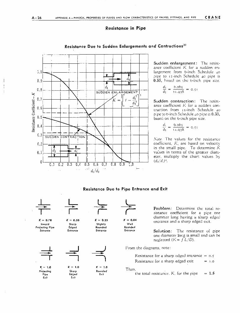
Resistance in Pipe
Resistance Due to Sudden Enlargements and Contractions”
K = 0.78 lnword
Projecting Pipe Entrance
K. = 1.0 Proiecting
Pipe Exit
Sudden enlargement : The resist- ance coefficient E: for a sudden en- largement from 6-inch Schedule 40 pipe to 12-inch Schedule 40 pipe is 0.55, hasecl on the 6-inch pipe s i x
d, 6.06j - 0 . 5 1 _ -
dr I 1.938
Sudden contraction : The resist- ance coefficient I< for a sudden con- traction from 12-inch Schedule 40 pipe to 6-inch Schedule 40 pipe is 0.33, based on the 6-inch pipe size.
d, 6.06j - 0 . j l _ -
d? I 1 . ~ 3 8
.\ate The values for the resistance coefficient, I<, are based on velocit> in the small pipe To determine K values in terms of the greater diam- eter, multiply the chart values by (d?/dJ ’ .
Resistance Due to Pipe Entrance and Exit
+ d _t Problem: Determine the total re- L 7
I 7
I 7
sistance coefficient for a pipe one diameter long having a sharp edged entrance and a sharp edged exit.
I I I K = 0.50 K = 0.23 K = 0.04
Sharp Slightly Well Edged Rounded Rounded
Entronce Entrance Entrance Solution: The resistance of pipe one diameter long is small and can be neglected (I< = J L I D ) .
From the diagrams, note: d -
Resistance for a sharp edged entrance = 0 . 5 I I 1 Resistance for a sharp edged exit = 1.0
K = 1.0 K = 1.0 Shorp Rounded Then, Edged Exit the total resistance, K, for the pipe = 1.5
Exit
c R A N E APPENDIX A-PHYSICAL PROPERTIES OF FLUIDS AND FLOW CHARACTERISTICS OF VALVES, FITTINGS, AND PIPE A - 2 7
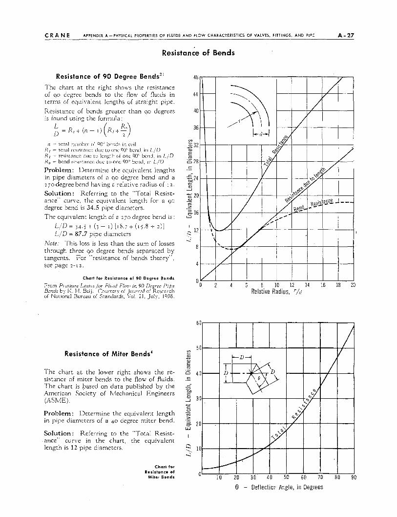
Resistance of Bends
Resistance of 90 Degree Bendsz1 The chart a t the right sho\\s the resistance of 90 degree bends to the flow of flulds in terms of equivalent lengths of straight pipe. Resistance of bends greater than 90 degrees is found using the formula:
n = total nuinbcr of 90" bends in coil I < ( = total rcsistancc due to onc QO' bcnd in L I D R1 = rcsistnncc duc to Icn:_ltti or onc 9U" hciid. in I - jD Rh = bend wvstaticc duc io onc 90" bcnd, in L / D
Problem: Determine the equivalent lengths in pipe diameters of a 90 degree bend and a 2 j o degree bend ha\ring a re1atiX.e radius of I 2 .
Solution: Referring to the "Total Resist- ance" curire, the equi\.alent length for a 92 degree bend is 34.5 pipe diame:ers. The equivalent iength of a 270 degree bend is :
L I D = 3q. j + (3 - 1) [ I P . ~ + ( I j . 8 + 2 ) ]
L / D = 87.7 pipe diameters Note: This loss is less than the sum of losses through three 90 degree bends separated by tangents. For "resistance of bends theory", see page 1-12 .
Chart for Resisfance of 90 Degree Bends
From Pressure Losses /or Fluid F/OIP ir. 90 Dcgree Pibe Brnds by I<. H. Bcij. Courtesy of Journal oi Kcscarcli oi National Burca~i oi Standards, \'d. 21, July, 1938.
48
44
40
36
co 2 32
5 a,
0 28 t
t
e W 2
.-
24
-E 20
16
(u
rn > - .- W
I 12
8
2 .-:
4
0
Resistance of Miter Bends4
The chart a t the iower right shows the re- sistance of miter bends to the flow of fluids. The chart is based on data published by the American Society of Mechanical Engineers (AShE).
Problem: Determine the equivalent length in pipe dianieters of a 40 degree miter bend.
Solution : Referring to the "Total Resist- ance" curve In the chart, the equivalent length is 12 pipe diameters.
-I
I
3 ... 4
2 4 6 8 10 12 14 16 18 Relat ive Radius, r/o
Chart for Resirtanca of
Miter Bends
8 - Deflection Angle, in Degrees