Embed Size (px)
DESCRIPTION
Creating maps composed of polygons and polylines within a Geographic Information System (GIS) software, such as ArcGIS, is a common task for many GIS professionals across multiple disciplines. The [22] development of these types of maps can be a complex and labor intensive process. This is especially true when creating geologic maps, which represent a complex network of geologic units, faults, joints, and other features, often with cross-cutting relationships. Those who have tried to create a map like this probably realized, early in the process, that it is not as straight-forward as they imagined due to the many different work-flow patterns that exist for creating maps in a GIS. In this presentation, we will discuss common problems and how to manage them, as well as give suggestions that will make your next geologic mapping project more streamlined and organized.
Citation preview
GEOLOGIC MAPPING 101: COMMON PITFALLS AND SUGGESTIONS
FOR A MORE EFFICIENT APPROACH
Mark Zellman1 & Kristi Zellman2
1Fugro Consultants, Inc. 2Colorado School of Mines and U.S. Geological Survey
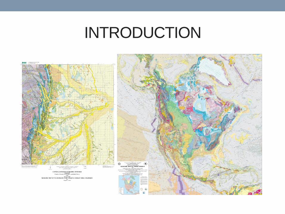
INTRODUCTION

COMMON TASKS
• Converting raster maps to vectors
• Scanned paper maps
• Digital raster images
• Cleaning up vector messes
• Symbolizing
• Attributing
• Metadata
• Publishing Raster Source
Vector Lines
Polygons
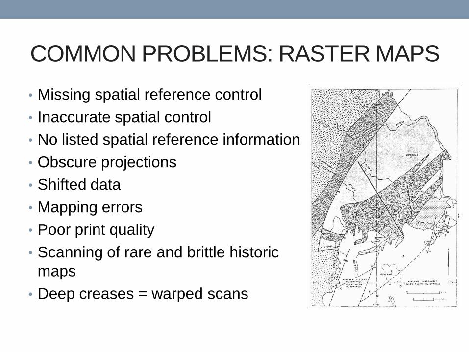
COMMON PROBLEMS: RASTER MAPS
• Missing spatial reference control
• Inaccurate spatial control
• No listed spatial reference information
• Obscure projections
• Shifted data
• Mapping errors
• Poor print quality
• Scanning of rare and brittle historic
maps
• Deep creases = warped scans
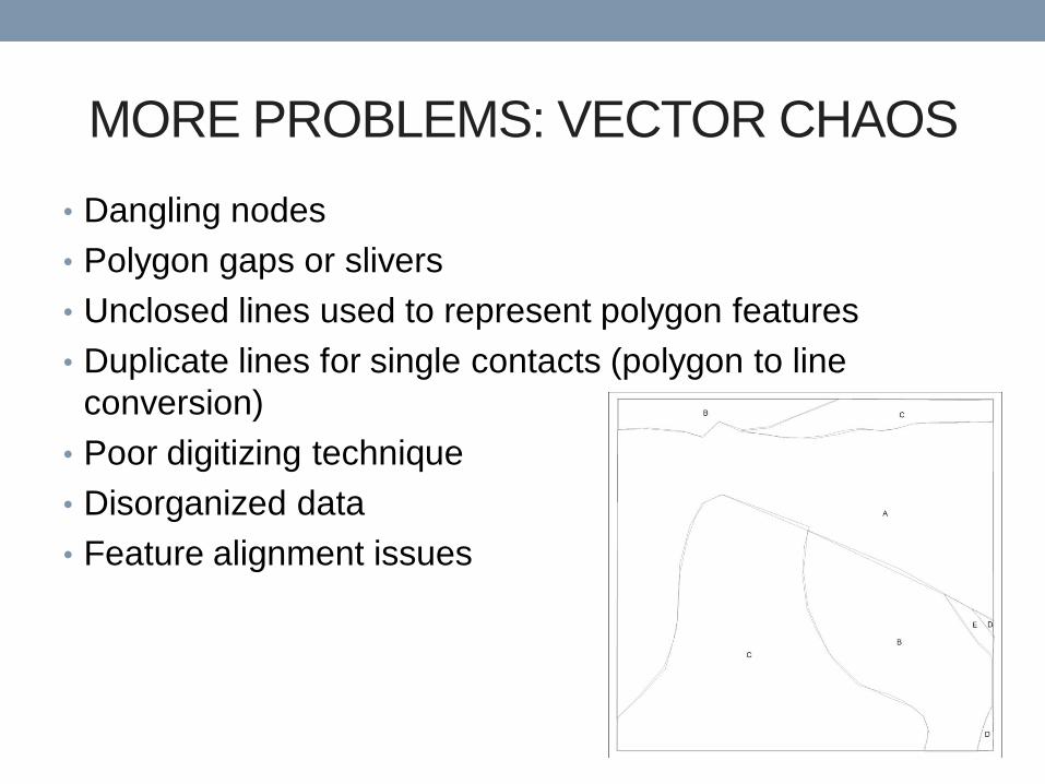
MORE PROBLEMS: VECTOR CHAOS
• Dangling nodes
• Polygon gaps or slivers
• Unclosed lines used to represent polygon features
• Duplicate lines for single contacts (polygon to line
conversion)
• Poor digitizing technique
• Disorganized data
• Feature alignment issues
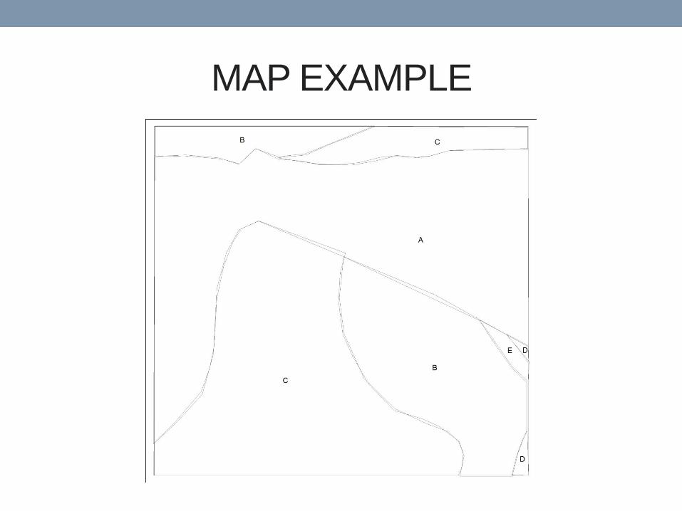
MAP EXAMPLE
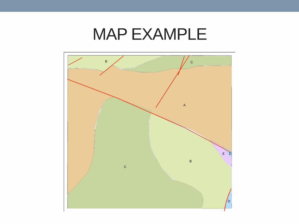
MAP EXAMPLE
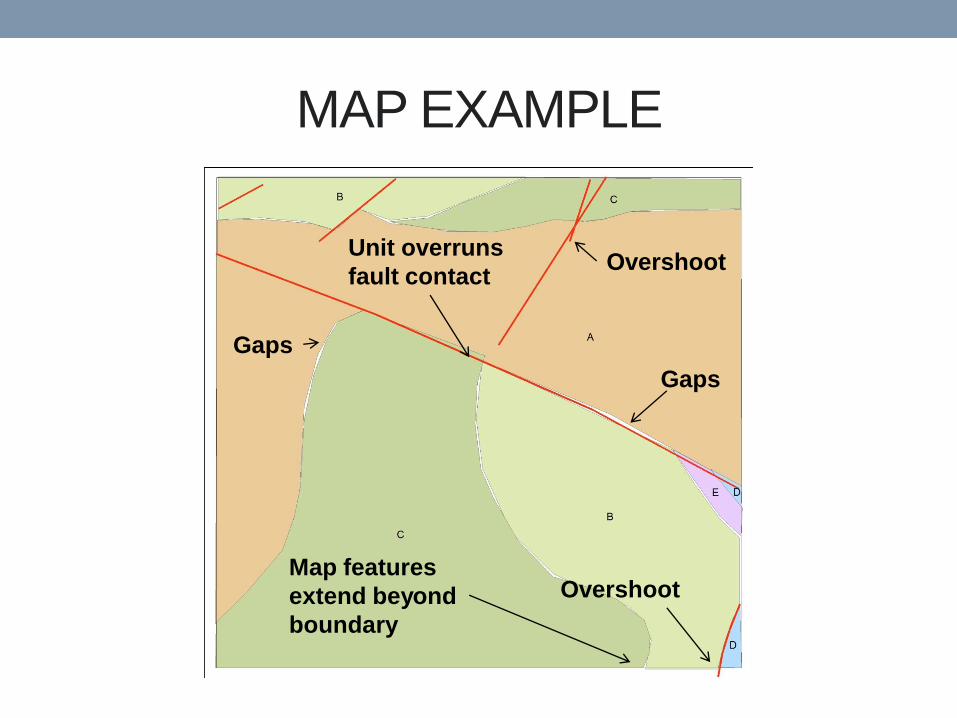
MAP EXAMPLE
Unit overruns
fault contact
Gaps
Overshoot
Overshoot Map features
extend beyond
boundary
Gaps
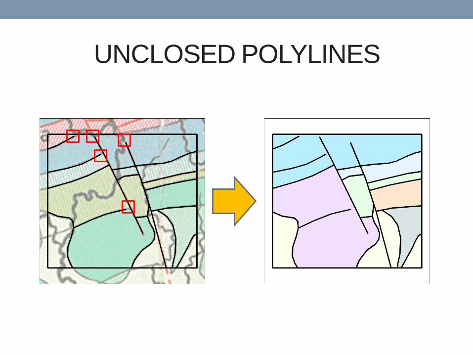
UNCLOSED POLYLINES
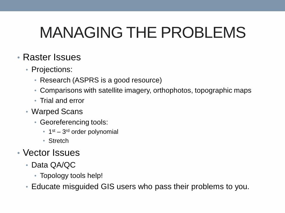
MANAGING THE PROBLEMS
• Raster Issues
• Projections:
• Research (ASPRS is a good resource)
• Comparisons with satellite imagery, orthophotos, topographic maps
• Trial and error
• Warped Scans
• Georeferencing tools:
• 1st – 3rd order polynomial
• Stretch
• Vector Issues
• Data QA/QC
• Topology tools help!
• Educate misguided GIS users who pass their problems to you.
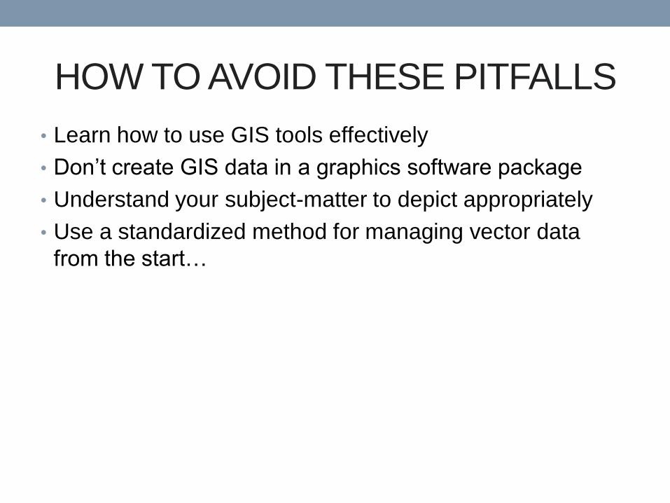
HOW TO AVOID THESE PITFALLS
• Learn how to use GIS tools effectively
• Don’t create GIS data in a graphics software package
• Understand your subject-matter to depict appropriately
• Use a standardized method for managing vector data
from the start…
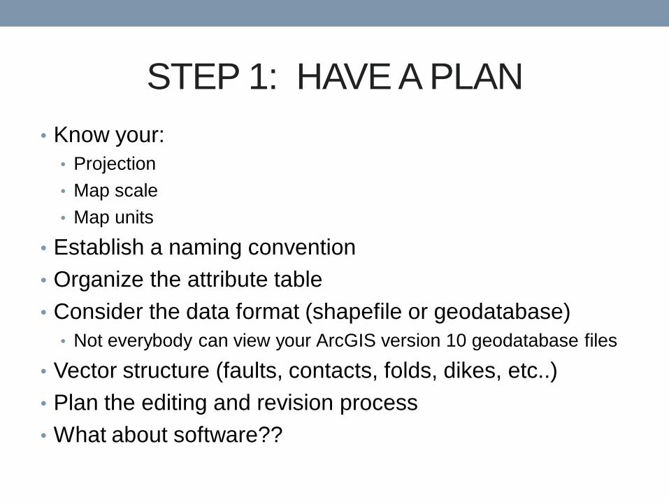
STEP 1: HAVE A PLAN
• Know your:
• Projection
• Map scale
• Map units
• Establish a naming convention
• Organize the attribute table
• Consider the data format (shapefile or geodatabase)
• Not everybody can view your ArcGIS version 10 geodatabase files
• Vector structure (faults, contacts, folds, dikes, etc..)
• Plan the editing and revision process
• What about software??
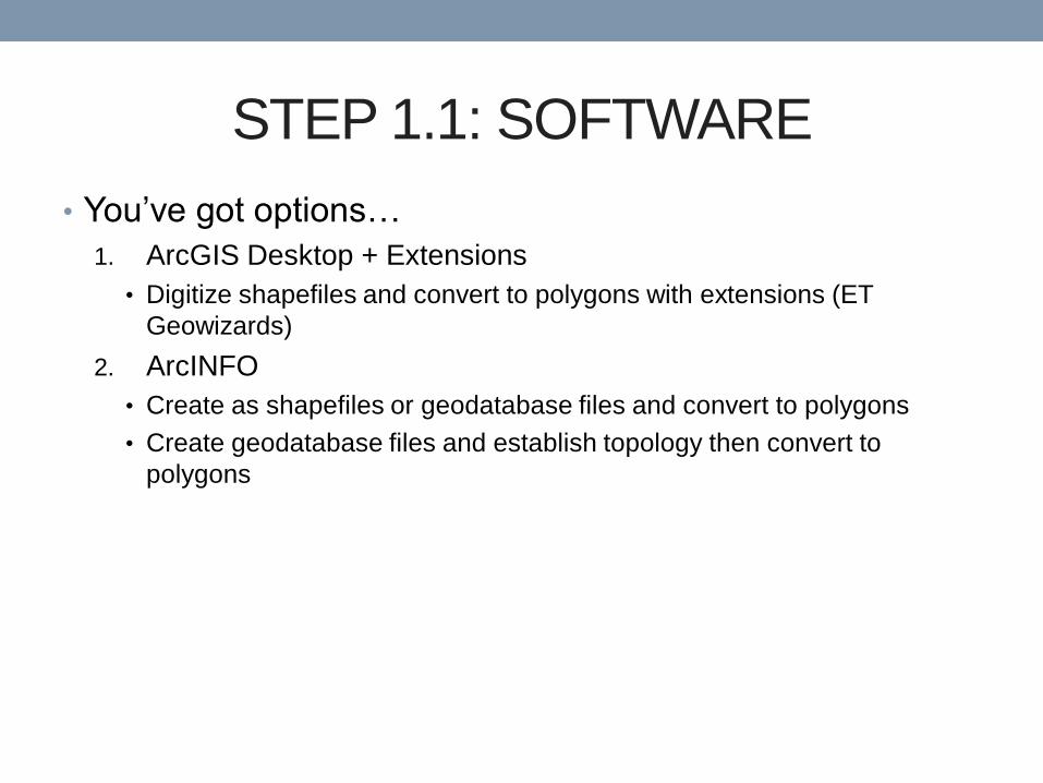
STEP 1.1: SOFTWARE
• You’ve got options…
1. ArcGIS Desktop + Extensions
• Digitize shapefiles and convert to polygons with extensions (ET
Geowizards)
2. ArcINFO
• Create as shapefiles or geodatabase files and convert to polygons
• Create geodatabase files and establish topology then convert to
polygons
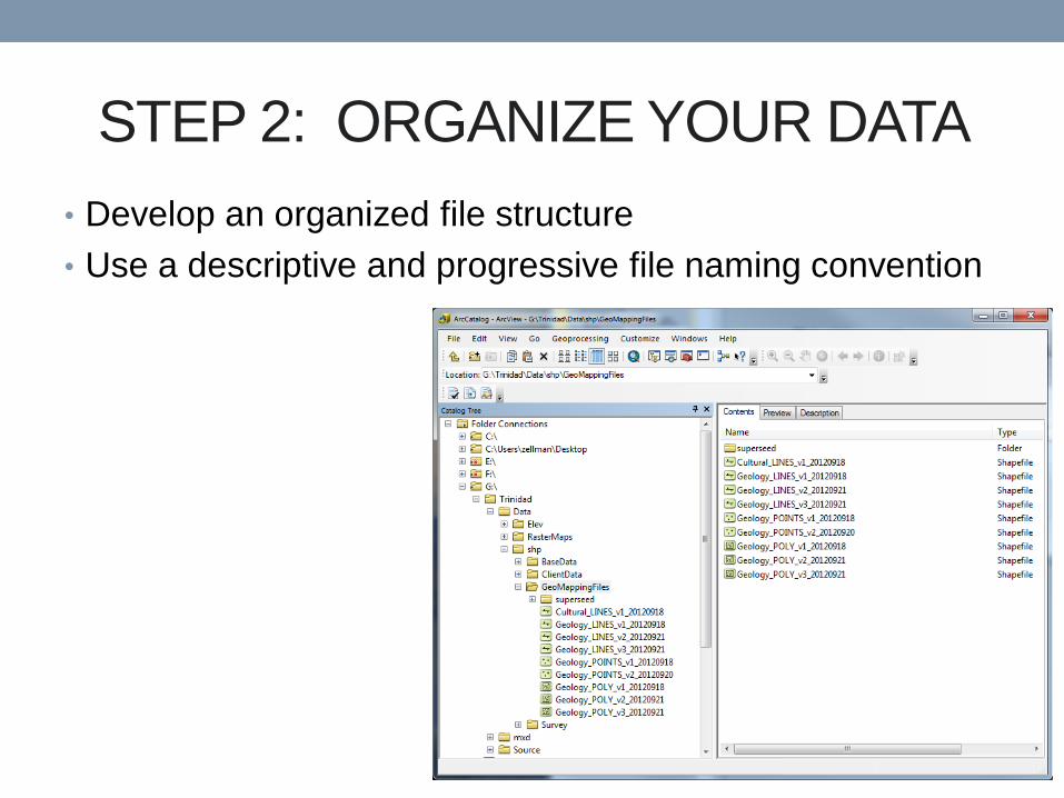
STEP 2: ORGANIZE YOUR DATA
• Develop an organized file structure
• Use a descriptive and progressive file naming convention
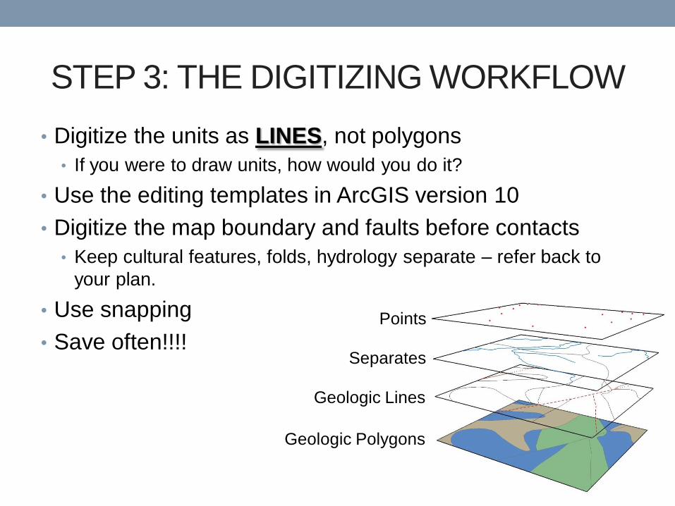
STEP 3: THE DIGITIZING WORKFLOW
• Digitize the units as LINES, not polygons
• If you were to draw units, how would you do it?
• Use the editing templates in ArcGIS version 10
• Digitize the map boundary and faults before contacts
• Keep cultural features, folds, hydrology separate – refer back to
your plan.
• Use snapping
• Save often!!!!
Points
Separates
Geologic Lines
Geologic Polygons
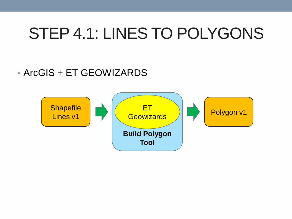
• ArcGIS + ET GEOWIZARDS
STEP 4.1: LINES TO POLYGONS
Build Polygon
Tool
Shapefile
Lines v1
ET
Geowizards Polygon v1
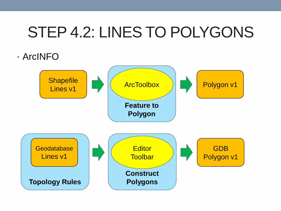
• ArcINFO
STEP 4.2: LINES TO POLYGONS
Feature to
Polygon
Shapefile
Lines v1 ArcToolbox Polygon v1
Construct
Polygons Topology Rules
Geodatabase
Lines v1 Editor
Toolbar
GDB
Polygon v1
STEP 5.1: THE EDITING PROCESS
• Maintain data organization and file naming conventions
• Develop an organized process for creating, editing and
updating files
• Edited polygons require updated attributes (preserve
attributes)
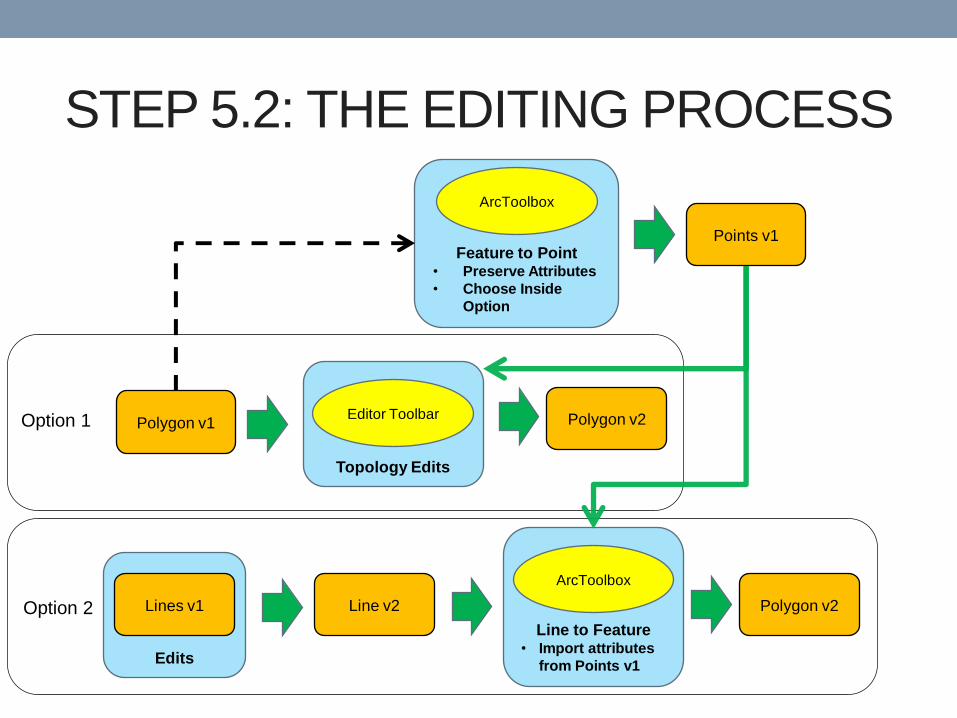
STEP 5.2: THE EDITING PROCESS
Polygon v1
Topology Edits
Editor Toolbar Polygon v2
Feature to Point • Preserve Attributes
• Choose Inside
Option
ArcToolbox
Points v1
Line v2
Line to Feature • Import attributes
from Points v1
ArcToolbox
Polygon v2
Edits
Lines v1
Option 1
Option 2
STEP 6: SYMBOLOGY AND ATTRIBUTES
• Use standard colors for unit polygons and standard
symbols for geologic features (ESRI, USGS)
• FGDC Digital Cartographic Standard for Geologic Map
Symbolization (FGDC, 2006)
• ESRI Geologic Map Template
• ESRI symbol template pallet
• Important traits for attributes
• Consistency
• Limitation
• Descriptive
• Easy for a user to interpret
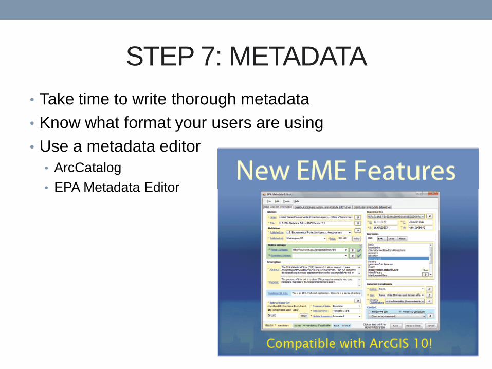
STEP 7: METADATA
• Take time to write thorough metadata
• Know what format your users are using
• Use a metadata editor
• ArcCatalog
• EPA Metadata Editor
CONCLUSION
• These approaches can be applied to projects in other
disciplines
• To avoid common mapping pitfalls:
• Take the time to make a plan before you start a GIS project
• Understand your subject matter and audience
• Always take the time to write thorough metadata
• A standard and organized approach is necessary
REFERENCES Federal Geographic Data Committee [prepared for the Federal Geographic Data Committee by the U.S. Geological
Survey], 2006, FGDC Digital Cartographic Standard for Geologic Map Symbolization: Reston, Va., Federal Geographic Data
Committee Document Number FGDC-STD-013-2006, 290 p., 2 plates.
EPA Metadata Editor (EME), version 3.1.2, 2012; https://edg.epa.gov/EME/Home.htm
Thank You!
Questions?