Embed Size (px)
Citation preview

2017.12
High current plug-in connectorwith a wrong insertion prevention mechanism

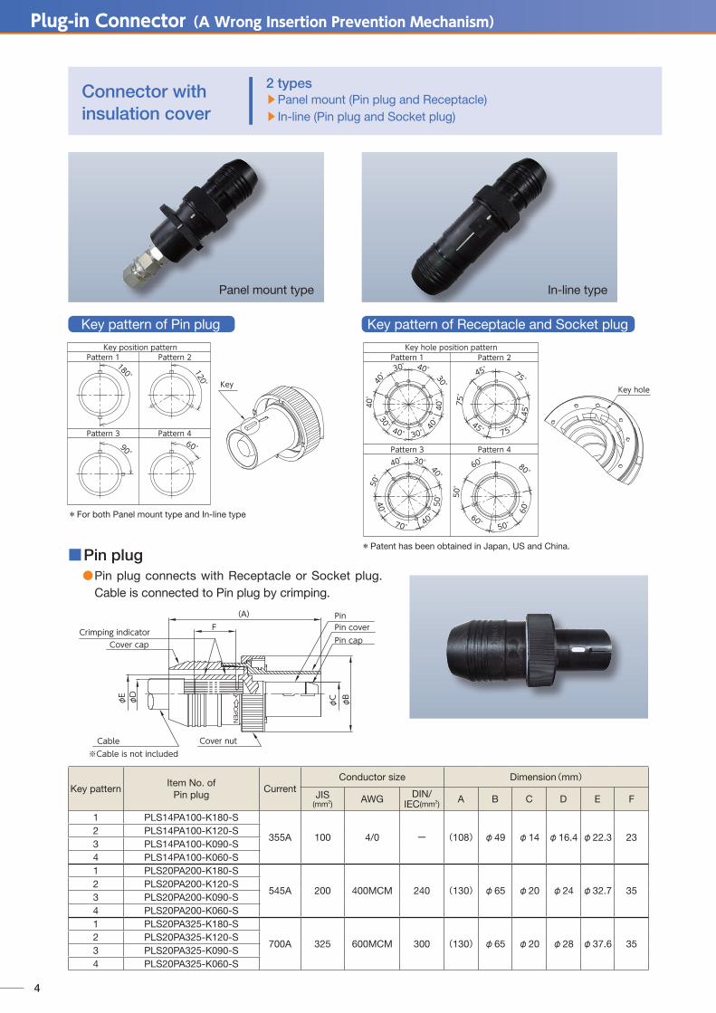
Plug-in Connector (A Wrong Insertion Prevention Mechanism)
2
■ Contact structure Fundamental principle of the band contact
● In order to flow the electricity between the two different metal (pin, socket), it has the roll of the bridge.
● By the excellent spring characteristics, each contact surface is pressed with a constant force and the contact pressure is held in a stable state.
●Multiple louvers form each independent contact. ●The contact resistance is significantly reduced by parallel contact of each louver.
R=r÷n R:Contact resistance of the connector. r:Contact resistance per one louver. n: The number of louver in a band contact
used to the connector.
● Equipped with a wrong insertion to other polarity (4 kinds) prevention mechanism. 【Patent: cooperative application with NTT FACILITIES,INC. settled.】The wrong insertion prevention mechanism with concave-convex shaped key holes is adopted. Thus the prevention mechanism of electric shock and short circuit accident due to installation mistake is provided.
● Attachable / detachable by small force● Using the band contact made of
beryllium copper alloy High current removable design is available.
● Silver plating adopted Stable and long-term connection reliability can be obtained.
● Connected with a commercially available tool (JIS crimping tool) Special tool is unnecessary to connect a cable.
● Long term stability
Due to the adoption of the plug-in structure, long-term stability is provided, also maintenance and management man-hour reduction is provided.
● Screw type lock structure The tightening indication line and the feeling to ride onto given by the lock structure, facilitate the completion confirmation of the connection.
● Identification indicator (Option) By attaching the identification cover・identification ring, the connection system can be confirmed with the naked eye.
Features of the high current plug-in connector with a wrong insertion prevention mechanism
2.54mm
0.15mm
17.5mm
1.2~1.4mmLouver

3
■Connector specification ●Contact material: Silver plated beryllium copper alloy. ●Metal conductor material: Silver plated electrolytic copper. ● Insulation cover material: PBT (UL94 V-O)
※ Identification cover: Polyvinyl chloride. ●Cable connection method: Same as JIS C 2805 ”Crimp-terminal lugs for copper conductor” ●Rated current: 355A (100mm2), 545A (200mm2), 700A (325mm2) ●Rated voltage: 600V/DC・AC ● Maximum operating temperature: 100℃ (Includes temperature rise by current) ●Connecting cable kind: CF・CV・EM-LMFC, etc.
■Crimping direction When crimping, fix up the Crimping die (Indenter side)
on the slit side of the cylindrical portion, as shown in the right figure.
【Receptacle Structural drawing】■Panel mounting hole size
■Connector crimping condition
Specification of the high current plug-in connector with a wrong insertion prevention mechanism
Cable
Pin
Slit ※Note the direction
Crimping die(Anvil side)
Crimping die(Indenter side)
Cylindrical portion
φD through hole orME Screw hole
φA(through hole)
(C)
(C
)
φB(P.C.D)
Panel back surfacePanel front surface
Conductor size(mm2) Cable kind Connector crimping condition *1
Crimping tool Crimping die Crimping times
100 CF/CV/EM-LMFC etc. Hydraulic tool *2 Indenter side 70-100 Once one sideAnvil side 100
200 CF/CV/EM-LMFC etc. Hydraulic tool *2 Indenter side 150-200 Once one sideAnvil side 200
325 CF/CV/EM-LMFC etc. Hydraulic tool *2 Indenter side 325 Once one sideAnvil side 325
*1: According to JIS C 2805 “Crimp-type terminal lugs for copper conductor”*2: According to JIS C 9711 “Compression tools for wire connectors of interior wiring”
Pin diameter(mm) Dimension(mm)A B C D E
φ14 φ41 φ58 (41.0) φ5 M4φ20 φ58 φ81 (57.3) φ6 M5
* Installation of the panels, etc. is only from the panel front.
*Note: Mounting and removal during energization is unavailable. Don’t perform it in any way because it is dangerous.
Plug-in Connector (A Wrong Insertion Prevention Mechanism)
4
■Pin plug ● Pin plug connects with Receptacle or Socket plug.
Cable is connected to Pin plug by crimping.
Connector withinsulation cover
φC
Pin capPin coverPin
φB
Cable
φE φD
Crimping indicator
※Cable is not includedCover nut
Cover cap
OPEN
(A)F
2 types▶Panel mount (Pin plug and Receptacle)▶ In-line (Pin plug and Socket plug)
Key patternItem No. of
Pin plugCurrent
Conductor size Dimension(mm)
JIS(mm2) AWG DIN/
IEC(mm2) A B C D E F
1 PLS14PA100-K180-S
355A 100 4/0 ー (108) φ49 φ14 φ16.4 φ22.3 232 PLS14PA100-K120-S3 PLS14PA100-K090-S4 PLS14PA100-K060-S1 PLS20PA200-K180-S
545A 200 400MCM 240 (130) φ65 φ20 φ24 φ32.7 352 PLS20PA200-K120-S3 PLS20PA200-K090-S4 PLS20PA200-K060-S1 PLS20PA325-K180-S
700A 325 600MCM 300 (130) φ65 φ20 φ28 φ37.6 352 PLS20PA325-K120-S3 PLS20PA325-K090-S4 PLS20PA325-K060-S
Key position patternPattern 1 Pattern 2
Pattern 3 Pattern 4
180°Key
120°
90°60°
Key hole
Key hole position patternPattern 1 Pattern 2
Pattern 3 Pattern 430°40°
50°
40°
70°
60°50
°
60° 50°60
°
80°
30°
30°
30°
30°
40°
40°
40°
40°
40°
40°
40°
50°
40°
75°
45°
75°45°
75°
45°
Panel mount type In-line type
*Patent has been obtained in Japan, US and China.
*For both Panel mount type and In-line type
Key pattern of Pin plug Key pattern of Receptacle and Socket plug

5
■Socket plug ● Socket plug connects with Pin plug.
Cable is connected to Socket plug by crimping.
(A)F
Cable
φC φEφD
Crimping indicator
Socket cover
Socket capCover capSocket
Band contact
φB
※Cable is not included
■Receptacle ● Receptacle connects with Pin plug.
Busbar is connected to Receptacle with screw nut.
Socket
φC
DBand contactSocket cap
Socket cover
(A)
φB□K
GH
φE
F
Keypattern
Item No. ofSocket plug
CurrentConductor size Dimension(mm)
JIS(mm2) AWG DIN/
IEC(mm2) A B C D E F
1 PLS20PB200-K180-S
545A 200 400MCM 240 (135) φ65 φ20 φ24 φ32.7 352 PLS20PB200-K120-S3 PLS20PB200-K090-S4 PLS20PB200-K060-S1 PLS20PB325-K180-S
700A 325 600MCM 300 (135) φ65 φ20 φ28 φ37.6 352 PLS20PB325-K120-S3 PLS20PB325-K090-S4 PLS20PB325-K060-S
Key pattern
Item No. ofReceptacle
CurrentConductor size Dimension(mm)
JIS(mm2) AWG DIN/
IEC(mm2) A B C D E F G H K
1 PLS14RBM14-K180-S
355A 100 4/0 ー (123) φ49 φ14 M14 φ39 56 36 6 □502 PLS14RBM14-K120-S3 PLS14RBM14-K090-S4 PLS14RBM14-K060-S1 PLS20RBM20-K180-S
545A・
700A
200
~
325
400MCM
~
600MCM
240
~
300(152) φ65 φ20 M20 φ56 73 43 8 □71
2 PLS20RBM20-K120-S3 PLS20RBM20-K090-S4 PLS20RBM20-K060-S

Plug-in Connector (A Wrong Insertion Prevention Mechanism)
6
■Structural drawing after insertion
OPEN
(L1)
(L2)
OPEN
(L1)
Connection type
Key pattern
Item No. ofPin plug
Item No. ofReceptacle
Item No. ofSocket plug
Dimension(mm) Conductor size
L1 L2 JIS(mm2) AWG DIN/
IEC(mm2)
Panel mount
1 PLS14PA100-K180-S PLS14RBM14-K180-S
(178) (91) 100 4/0 ー2 PLS14PA100-K120-S PLS14RBM14-K120-S3 PLS14PA100-K090-S PLS14RBM14-K090-S4 PLS14PA100-K060-S PLS14RBM14-K060-S1 PLS20PA200-K180-S PLS20RBM20-K180-S
(225) (116) 200 400MCM 2402 PLS20PA200-K120-S PLS20RBM20-K120-S3 PLS20PA200-K090-S PLS20RBM20-K090-S4 PLS20PA200-K060-S PLS20RBM20-K060-S1 PLS20PA325-K180-S PLS20RBM20-K180-S
(225) (116) 325 600MCM 3002 PLS20PA325-K120-S PLS20RBM20-K120-S3 PLS20PA325-K090-S PLS20RBM20-K090-S4 PLS20PA325-K060-S PLS20RBM20-K060-S
In-line
1 PLS20PA200-K180-S PLS20PB200-K180-S
(208) 200 400MCM 2402 PLS20PA200-K120-S PLS20PB200-K120-S3 PLS20PA200-K090-S PLS20PB200-K090-S4 PLS20PA200-K060-S PLS20PB200-K060-S1 PLS20PA325-K180-S PLS20PB325-K180-S
(208) 325 600MCM 3002 PLS20PA325-K120-S PLS20PB325-K120-S3 PLS20PA325-K090-S PLS20PB325-K090-S4 PLS20PA325-K060-S PLS20PB325-K060-S
Socket cap
Socket cap
Socket (screw)
Cable
Pin
Cover nut
Pin cover
Cover cap
Cover cap
Cable
Socket cover(compression type)
Socket cover
Socket (compression type)
Washers and nuts
【Structural drawing of Pin plug】
【Structural drawing of Receptacle】
【Structural drawing of Socket plug】
【Panel mount type】 【In-line type】

7
■ Identification cover ●Possible to be attached to the Pin plug and the Socket plug.
■ Identification ring ●Possible to be attached to the Receptacle.
■Socket end cap ●Possible to be attached to the Receptacle and the Socket plug.
A
φC
φB
T
B
φA
OPEN
OPEN
PBT
PBT
A
φB
ColorItem No. of
Identification cover
Conductor size Dimension (mm)JIS
(mm2) AWG DIN/IEC(mm2) A B C T
Red PLS14P100-IC-RED-P100 4/0 ー 57 φ20 φ36.5 2White PLS14P100-IC-WHT-P
Blue PLS14P100-IC-BLE-PRed PLS20P200-IC-RED-P
200 400MCM 240 75 φ26.5 φ53 2White PLS20P200-IC-WHT-PBlue PLS20P200-IC-BLE-PRed PLS20P325-IC-RED-P
325 600MCM 300 80 φ32.5 φ53 2.5White PLS20P325-IC-WHT-PBlue PLS20P325-IC-BLE-P
ColorItem No. of
Identification ringPin diameter(mm)
Dimension(mm)A B
Red PLS14P100-IR-REDφ14 φ40 6.5White PLS14P100-IR-WHT
Blue PLS14P100-IR-BLERed PLS20P200-IR-RED
φ20 φ57 10White PLS20P200-IR-WHTBlue PLS20P200-IR-BLE
ColorItem No. of
Socket end capPin diameter
(mm)Dimension(mm)
A B
Black PLS14SBK-NTF φ14 34 φ49PLS20SBK-NTF φ20 36 φ65
▶When option is necessary; please specify the model number in the table below.
Implementation example
Implementation example
Implementation example
Option

EC-349 2I12J-PIC-1-1309/Cat.402b
● Customized to the intended use, we will perform various designing and manufacturing.
Head office 2-11-16, Azamino Minami, Aoba-ku, Yokohama-shi, Kanagawa 225-0012, JapanOverseas Sales Department TEL.+81-45-910-2814 FAX.+81-45-910-2839
http://www.feps.co.jp/english/
The products and their appearances, as described in this brochure, are subject to change for improvement without prior notice.
Export Control RegulationsThe products and/or technical information presented in this publication may be subject to the application of the Foreign Exchange and Foreign Trade Act and other related laws and regulations in Japan.In addition, the Export Administration Regulations (EAR) of the United States may be applicable.In cases where exporting or reexporting the products and/or technical information presented in this publication, customers are requested to follow the necessary procedures at their own responsibility and cost.Please contact the Ministry of Economy, Trade and Industry of Japan or the Department of Commerce of the United States for details about procedures.