Embed Size (px)
Citation preview
Installation Instructions
Micro810 12 Point Programmable Controllers Catalog Numbers 2080-LC10-12AWA, 2080-LC10-12QWB, 2080-LC10-12QBB, 2080-LC10-12DWD
http://rockwellautomation.com/literature
FRCette publication est disponible en français sous forme électronique (fichier PDF). Pour la télécharger, rendez-vous sur la page Internet indiquée ci-dessus.
PTEsta publicação está disponível em portugués como PDF. Vá ao endereço web que aparece acima para encontrar e fazer download da publicação.
ITQuesta pubblicazione è disponibile in Italiano in formato PDF. Per scaricarla collegarsi al sito Web indicato sopra.
ZH
DEDiese Publikation ist als PDF auf Deutsch verfügbar. Gehen Sie auf die oben genannte Web-Adresse, um nach der Publikation zu suchen und sie herunterzuladen.
ZC
ESEsta publicación está disponible en español como PDF. Diríjase a la dirección web indicada arriba para buscar y descarga esta publicación. KO
Table of Contents
Topic Page
Important User Information 2
Additional Resources 6
Overview 7
Controller Overview 7
Mount the Module 8
Wire the Controller 11
Specifications 12
2 Micro810 12 Point Programmable Controllers
Important User InformationSolid state equipment has operational characteristics differing from those of electromechanical equipment. Safety Guidelines for the Application, Installation and Maintenance of Solid State Controls (Publication SGI-1.1 available from your local Rockwell Automation sales office or online at http://rockwellautomation.com/literature) describes some important differences between solid state equipment and hard-wired electromechanical devices. Because of this difference, and also because of the wide variety of uses for solid state equipment, all persons responsible for applying this equipment must satisfy themselves that each intended application of this equipment is acceptable.In no event will Rockwell Automation, Inc. be responsible or liable for indirect or consequential damages resulting from the use or application of this equipment.The examples and diagrams in this manual are included solely for illustrative purposes. Because of the many variables and requirements associated with any particular installation, Rockwell Automation, Inc. cannot assume responsibility or liability for actual use based on the examples and diagrams.No patent liability is assumed by Rockwell Automation, Inc. with respect to use of information, circuits, equipment, or software described in this manual.Reproduction of the contents of this manual, in whole or in part, without written permission of Rockwell Automation, Inc., is prohibited.Throughout this manual, when necessary, we use notes to make you aware of safety considerations.
WARNING: Identifies information about practices or circumstances that can cause an explosion in a hazardous environment, which may lead to personal injury or death, property damage, or economic loss.
ATTENTION: Identifies information about practices or circumstances that can lead to personal injury or death, property damage, or economic loss. Attentions help you identify a hazard, avoid a hazard and recognize the consequences.
SHOCK HAZARD: Labels may be on or inside the equipment (for example, drive or motor) to alert people that dangerous voltage may be present.
BURN HAZARD: Labels may be on or inside the equipment (for example, drive or motor) to alert people that surfaces may reach dangerous temperatures.
IMPORTANT IMPORTANT: Identifies information that is critical for successful application and understanding of the product.
Publication 2080-IN006B-EN-P - April 2014
Micro810 12 Point Programmable Controllers 3
Environment and Enclosure
Preventing Electrostatic Discharge
ATTENTION: This equipment is intended for use in a Pollution Degree 2 industrial environment, in overvoltage Category II applications (as defined in IEC 60664-1), at altitudes up to 2000 m (6562 ft) without derating.
This equipment is considered Group 1, Class A industrial equipment according to IEC/CISPR 11. Without appropriate precautions, there may be difficulties with electromagnetic compatibility in residential and other environments due to conducted and radiated disturbances.
This equipment is supplied as open-type equipment. It must be mounted within an enclosure that is suitably designed for those specific environmental conditions that will be present and appropriately designed to prevent personal injury resulting from accessibility to live parts. The enclosure must have suitable flame-retardant properties to prevent or minimize the spread of flame, complying with a flame spread rating of 5VA, V2, V1, V0 (or equivalent) if non-metallic. The interior of the enclosure must be accessible only by the use of a tool. Subsequent sections of this publication may contain additional information regarding specific enclosure type ratings that are required to comply with certain product safety certifications.
In addition to this publication, see:
• Industrial Automation Wiring and Grounding Guidelines, Rockwell Automation publication 1770-4.1, for additional installation requirements.
• NEMA Standard 250 and IEC 60529, as applicable, for explanations of the degrees of protection provided by different types of enclosure.
ATTENTION: This equipment is sensitive to electrostatic discharge, which can cause internal damage and affect normal operation. Follow these guidelines when you handle this equipment:
• Touch a grounded object to discharge potential static.
• Wear an approved grounding wriststrap.
• Do not touch connectors or pins on component boards.
• Do not touch circuit components inside the equipment.
• Use a static-safe workstation, if available.
• Store the equipment in appropriate static-safe packaging when not in use.
Publication 2080-IN006B-EN-P - April 2014
4 Micro810 12 Point Programmable Controllers
North American Hazardous Location ApprovalThe following modules are North American Hazardous Location approved: 2080-LC10-12AWA, 2080-LC10-12QWB, 2080-LC10-12QBB, 2080-LC10-12DWD
The following information applies when operating this equipment in hazardous locations:
Informations sur l’utilisation de cet équipement en environnements dangereux:
Products marked "CL I, DIV 2, GP A, B, C, D" are suitable for use in Class I Division 2 Groups A, B, C, D, Hazardous Locations and nonhazardous locations only. Each product is supplied with markings on the rating nameplate indicating the hazardous location temperature code. When combining products within a system, the most adverse temperature code (lowest "T" number) may be used to help determine the overall temperature code of the system. Combinations of equipment in your system are subject to investigation by the local Authority Having Jurisdiction at the time of installation.
Les produits marqués "CL I, DIV 2, GP A, B, C, D" ne conviennent qu'à une utilisation en environnements de Classe I Division 2 Groupes A, B, C, D dangereux et non dangereux. Chaque produit est livré avec des marquages sur sa plaque d'identification qui indiquent le code de température pour les environnements dangereux. Lorsque plusieurs produits sont combinés dans un système, le code de température le plus défavorable (code de température le plus faible) peut être utilisé pour déterminer le code de température global du système. Les combinaisons d'équipements dans le système sont sujettes à inspection par les autorités locales qualifiées au moment de l'installation.
WARNING: EXPLOSION HAZARD• Do not disconnect equipment
unless power has been removed or the area is known to be nonhazardous.
• Do not disconnect connections to this equipment unless power has been removed or the area is known to be nonhazardous. Secure any external connections that mate to this equipment by using screws, sliding latches, threaded connectors, or other means provided with this product.
• Substitution of any component may impair suitability for Class I, Division 2.
• If this product contains batteries, they must only be changed in an area known to be nonhazardous.
AVERTISSEMENT: RISQUE D’EXPLOSION• Couper le courant ou s'assurer
que l'environnement est classé non dangereux avant de débrancher l'équipement.
• Couper le courant ou s'assurer que l'environnement est classé non dangereux avant de débrancher les connecteurs. Fixer tous les connecteurs externes reliés à cet équipement à l'aide de vis, loquets coulissants, connecteurs filetés ou autres moyens fournis avec ce produit.
• La substitution de tout composant peut rendre cet équipement inadapté à une utilisation en environnement de Classe I, Division 2.
• S'assurer que l'environnement est classé non dangereux avant de changer les piles.
Publication 2080-IN006B-EN-P - April 2014
Micro810 12 Point Programmable Controllers 5
WARNING: • If you insert or remove the module while power is on, an electrical arc can
occur. This could cause an explosion in hazardous location installations.Be sure that power is removed or the area is nonhazardous before proceeding.
• The local programming terminal port is intended for temporary use only and must not be connected or disconnected unless the area is assured to be nonhazardous.
• When used in a Class I, Division 2, hazardous location, this equipment must be mounted in a suitable enclosure with proper wiring method that complies with the governing electrical codes.
• If you connect or disconnect wiring while the field-side power is on, an electrical arc can occur. This could cause an explosion in hazardous location installations. Be sure that power is removed or the area is nonhazardous before proceeding.
• The USB port is intended for temporary local programming purposes only and not intended for permanent connection. If you connect or disconnect the USB cable with power applied to this module or any device on the USB network, an electrical arc can occur. This could cause an explosion in hazardous location installations.Be sure that power is removed or the area is nonhazardous before proceeding.The USB port is a nonincendive field wiring connection for Class I, Division2 Groups A, B, C and D.
• Exposure to some chemicals may degrade the sealing properties of materials used in the Relays. It is recommended that the User periodically inspect these devices for any degradation of properties and replace the module if degradation is found.
ATTENTION:
• To comply with the CE Low Voltage Directive (LVD), this equipment must be powered from a source compliant with the following:Safety Extra Low Voltage (SELV) or Protected Extra Low Voltage (PELV).
• To comply with UL restrictions, this equipment must be powered from a Class 2 or Limited Voltage Limited Current Source (LVLC).
Publication 2080-IN006B-EN-P - April 2014
6 Micro810 12 Point Programmable Controllers
Additional Resources
If you would like a manual, you can:
• download a free electronic version from the Internet: http://literature.rockwellautomation.com
• purchase a printed manual by contacting your local Allen-Bradley distributor or Rockwell Automation representative
ATTENTION:
• Do not wire more than 2 conductors on any single terminal.
• Be careful when stripping wires. Wire fragments that fall into the controller could cause damage. Once wiring is complete, make sure the controller is free of all metal fragments.
• Do not remove the protective debris strips until after the controller and all other equipment in the panel near the module are mounted and wired. Remove strips before operating the controller. Failure to remove strips before operating can cause overheating.
• Electrostatic discharge can damage semiconductor devices inside the module. Do not touch the connector pins or other sensitive areas.
• The USB cable is not to exceed 3.0 m (9.84 ft).
• This product is intended to be mounted to a well-grounded mounting surface such as a metal panel. Additional grounding connections from the power supply's mounting tabs or DIN rail (if used) are not required unless the mounting surface cannot be grounded. Refer to Industrial Automation Wiring and Grounding Guidelines, Allen-Bradley publication 1770-4.1, for additional information.
Resource DescriptionMicro810® Programmable Controllers User Manual, publication 2080-UM001
A more detailed description of how to install and use your Micro810 programmable controller.
Micro800® AC Power Supply Installation Instruction, publication 2080-IN001
Information on wiring and installing the optional AC power supply.
Industrial Automation Wiring and Grounding Guidelines, publication 1770-4.1
More information on proper wiring and grounding techniques.
Publication 2080-IN006B-EN-P - April 2014

Micro810 12 Point Programmable Controllers 7
OverviewThe Micro810 12-point controller is an economical brick-style controller with embedded inputs and outputs. It can accommodate a USB adapter, and an LCD module.
It can also accommodate any 24V DC output power supply that meets minimum specifications such as the optional Micro800® power supply (for 2080-LC10-12QWB and 2080-LC10-12QBB only), 2080-PS120-240VAC.
Controller Overview
Status Indicator
State During normal operation During firmware update or program/data transfer
Off No power applied to device, or in Fault mode.
No power applied to device, or in Fault mode.
Solid green Device operating normally. Program transfer successful.
Flashing green Operating system error. Firmware update in progress.
45052
Status indicator
Input terminal block
Mounting screw hole/ mounting foot
USB port (for use with USB adapter only)
DIN rail mounting latch
Mounting screw hole/ mounting foot
Output connectors
Publication 2080-IN006B-EN-P - April 2014
8 Micro810 12 Point Programmable Controllers
Mount the ModuleMost applications require installation in an industrial enclosure to reduce the effects of electrical interference and environmental exposure. Locate your controller as far as possible from power lines, load lines, and other sources of electrical noise such as hard-contact switches, relays, and AC motor drives. For more information on proper grounding guidelines, see the Industrial Automation Wiring and Grounding Guidelines, publication 1770-4.1.
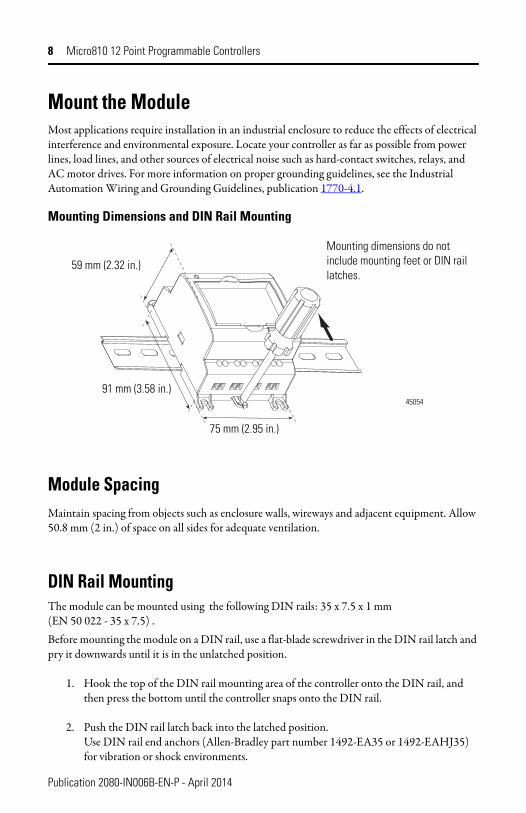
Mounting Dimensions and DIN Rail Mounting
Module SpacingMaintain spacing from objects such as enclosure walls, wireways and adjacent equipment. Allow 50.8 mm (2 in.) of space on all sides for adequate ventilation.
DIN Rail MountingThe module can be mounted using the following DIN rails: 35 x 7.5 x 1 mm (EN 50 022 - 35 x 7.5) .Before mounting the module on a DIN rail, use a flat-blade screwdriver in the DIN rail latch and pry it downwards until it is in the unlatched position.
1. Hook the top of the DIN rail mounting area of the controller onto the DIN rail, and then press the bottom until the controller snaps onto the DIN rail.
2. Push the DIN rail latch back into the latched position.Use DIN rail end anchors (Allen-Bradley part number 1492-EA35 or 1492-EAHJ35) for vibration or shock environments.
45054
Mounting dimensions do not include mounting feet or DIN rail latches.
75 mm (2.95 in.)
59 mm (2.32 in.)
91 mm (3.58 in.)
Publication 2080-IN006B-EN-P - April 2014
Micro810 12 Point Programmable Controllers 9
To remove your controller from the DIN rail, pry the DIN rail latch downwards until it is in the unlatched position.
Panel MountingThe preferred mounting method is to use four M4 (#8) screws per module. Hole spacing tolerance: ±0.4 mm (0.016 in.).
Follow these steps to install your controller using mounting screws.
1. Place the controller against the panel where you are mounting it. Make sure the controller is spaced properly.
2. Mark drilling holes through the mounting screw holes and mounting feet then remove the controller.
3. Drill the holes at the markings, then replace the controller and mount it.Leave the protective debris strip in place until you are finished wiring the controller and any other devices.
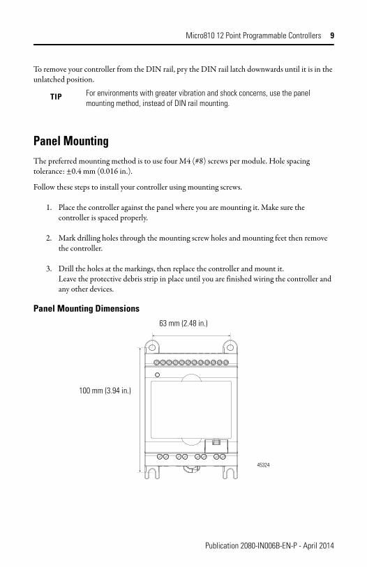
Panel Mounting Dimensions
TIP For environments with greater vibration and shock concerns, use the panel mounting method, instead of DIN rail mounting.
45324
63 mm (2.48 in.)
100 mm (3.94 in.)
Publication 2080-IN006B-EN-P - April 2014
10 Micro810 12 Point Programmable Controllers
Use Surge SuppressorsBecause of the potentially high current surges that occur when switching inductive load devices, such as motor starters and solenoids, we recommend the use of some type of surge suppression to protect and extend the operating life of the controllers output contacts. Switching inductive loads without surge suppression can significantly reduce the life expectancy of relay contacts. By adding a suppression device directly across the coil of an inductive device, you prolong the life of the output or relay contacts. You also reduce the effects of voltage transients and electrical noise from radiating into adjacent systems.
Refer to the Micro810 Programmable Controllers User Manual, publication 2080-UM001, for suitable surge suppression methods and recommended surge suppressors.
Publication 2080-IN006B-EN-P - April 2014
Micro810 12 Point Programmable Controllers 11
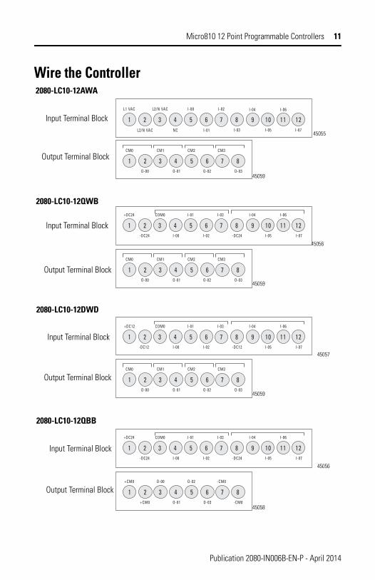
Wire the Controller
L2/N VAC
L1 VAC L2/N VAC
NC
I-00
I-01
I-02
1 2 3 4 5 6 7 8 9 10 11 12I-05 I-07I-03
I-04 I-06
45055
45056
2080-LC10-12AWA
2080-LC10-12QWB
2080-LC10-12DWD
45057
45058
CM0 CM1
O-03O-01O-00
CM2
O-02
1 2 3 4 5 6 7 8
CM3
45059
+DC24 COM0
-DC24I-00-DC24
I-01
I-02
1 2 3 4 5 6 7 8 9 10 11 12
I-03 I-04 I-06
I-05 I-07
CM0 CM1
O-03O-01O-00
CM2
O-02
1 2 3 4 5 6 7 8
CM3
45059
CM0 CM1
O-03O-01O-00
CM2
O-02
1 2 3 4 5 6 7 8
CM3
45059
2080-LC10-12QBB
45056
+DC24 COM0
-DC24I-00-DC24
I-01
I-02
1 2 3 4 5 6 7 8 9 10 11 12
I-03 I-04 I-06
I-05 I-07
COM0+DC12
-DC12I-00-DC12
I-01
I-02
1 2 3 4 5 6 7 8 9 10 11 12
I-03 I-04 I-06
I-05 I-07
+CM0 O-00
-CM0O-01 O-03+CM0
O-02
1 2 3 4 5 6 7 8
-CM0
Input Terminal Block
Output Terminal Block
Input Terminal Block
Output Terminal Block
Input Terminal Block
Output Terminal Block
Output Terminal Block
Input Terminal Block
Publication 2080-IN006B-EN-P - April 2014
12 Micro810 12 Point Programmable Controllers
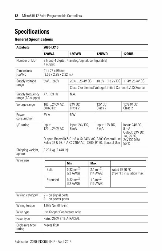
Specifications General Specifications
Attribute 2080-LC10
12AWA 12QWB 12DWD 12QBB
Number of I/O 8 Input (4 digital, 4 analog/digital, configurable)4 output
DimensionsHxWxD
91 x 75 x 59 mm(3.58 x 2.95 x 2.32 in.)
Supply voltage range
85V…263V 20.4…26.4V DC 10.8V…13.2V DC 11.4V..26.4V DC
Class 2 or Limited Voltage Limited Current (LVLC) Source
Supply frequency range (AC supply)
47…63 Hz N.A.
Voltage range 100…240V AC, 50/60 Hz
24V DCClass 2
12V DCClass 2
12/24V DCClass 2
Power consumption
5V A 5 W
I/O rating Input: 120…240V AC
Input: 24V DC, 8 mA
Input: 12V DC, 8 mA
Input: 24V DC, 8 mAOutput: 24V DC 1A, 25 °C, 24V DC 0.5A 55°C
Output: Relay 00 & 01: 8 A @ 240V AC, B300 General UseRelay 02 & 03: 4 A @ 240V AC, C300, R150, General Use
Shipping weight, approx.
0.203 kg (0.448 lb)
Wire size
Wiring category(1) 2 – on signal ports2 – on power ports
Wiring torque 1.085 Nm (8 lb-in.)
Wire type use Copper Conductors only
Fuse, type Rated 250V 3.15 A-RADIAL
Enclosure type rating
Meets IP20
Min Max
Solid 0.32 mm2
(22 AWG)2.1 mm2 (14 AWG)
rated @ 90 °C (194 °F ) insulation max
Stranded 0.32 mm2
(22 AWG)1.3 mm2 (16 AWG)
Publication 2080-IN006B-EN-P - April 2014
Micro810 12 Point Programmable Controllers 13
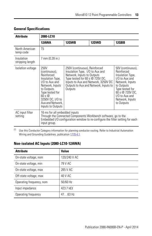
North American temp code
T5
Insulation stripping length
7 mm (0.28 in.)
Isolation voltage 250V (continuous), Reinforced Insulation Type, I/O to Aux and Network, Inputs to Outputs.Type tested for 60 s @ 3250V DC, I/O to Aux and Network, Inputs to Outputs
250V (continuous), Reinforced Insulation Type, I/O to Aux and Network, Inputs to OutputsType tested for 60 s @ 720V DC, Inputs to Aux and Network, 3250V DC Outputs to Aux and Network, Inputs to Outputs
50V (continuous), Reinforced Insulation Type, I/O to Aux and Network, Inputs to OutputsType tested for 60 s @ 720V DC, I/O to Aux and Network, Inputs to Outputs
AC input filter setting
16 ms for all embedded inputsThrough the Connected Components Workbench software, go to the Embedded I/O configuration window to re-configure the filter setting for each input group.
(1) Use this Conductor Category information for planning conductor routing. Refer to Industrial Automation Wiring and Grounding Guidelines, publication 1770-4.1.
Non-isolated AC Inputs (2080-LC10-12AWA)
Attribute Value
On-state voltage, nom 120/240 V AC
On-state voltage, min 79 V AC
On-state voltage, max 265 V AC
Off-state voltage, max 40 V AC
Operating frequency, nom 50/60 Hz
Input impedance 423.7 kΩ
Operating frequency 47…63 Hz
General Specifications
Attribute 2080-LC10
12AWA 12QWB 12DWD 12QBB
Publication 2080-IN006B-EN-P - April 2014
14 Micro810 12 Point Programmable Controllers
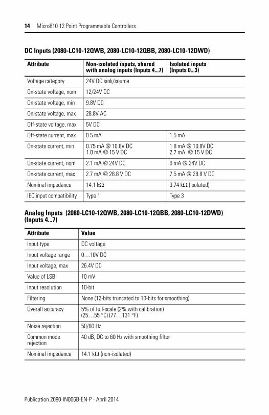
DC Inputs (2080-LC10-12QWB, 2080-LC10-12QBB, 2080-LC10-12DWD)
Attribute Non-isolated inputs, shared with analog inputs (Inputs 4...7)
Isolated inputs(Inputs 0...3)
Voltage category 24V DC sink/source
On-state voltage, nom 12/24V DC
On-state voltage, min 9.8V DC
On-state voltage, max 28.8V AC
Off-state voltage, max 5V DC
Off-state current, max 0.5 mA 1.5 mA
On-state current, min 0.75 mA @ 10.8V DC1.0 mA @ 15 V DC
1.8 mA @ 10.8V DC2.7 mA @ 15 V DC
On-state current, nom 2.1 mA @ 24V DC 6 mA @ 24V DC
On-state current, max 2.7 mA @ 28.8 V DC 7.5 mA @ 28.8 V DC
Nominal impedance 14.1 kΩ 3.74 kΩ (isolated)
IEC input compatibility Type 1 Type 3
Analog Inputs (2080-LC10-12QWB, 2080-LC10-12QBB, 2080-LC10-12DWD) (Inputs 4...7)
Attribute Value
Input type DC voltage
Input voltage range 0…10V DC
Input voltage, max 26.4V DC
Value of LSB 10 mV
Input resolution 10-bit
Filtering None (12-bits truncated to 10-bits for smoothing)
Overall accuracy 5% of full-scale (2% with calibration)(25…55 °C) (77…131 °F)
Noise rejection 50/60 Hz
Common mode rejection
40 dB, DC to 60 Hz with smoothing filter
Nominal impedance 14.1 kΩ (non-isolated)
Publication 2080-IN006B-EN-P - April 2014
Micro810 12 Point Programmable Controllers 15
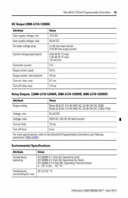
DC Output (2080-LC10-12QBB)
Attribute Value
User supply voltage, min 10 V DC
User supply voltage, max 26.4V DC
On-state voltage drop 1V @ max load current2.5V @ max surge current
Current ratings (each point) 0.5A @ 55 °C max1.0A @ 25 °C max1.0 mA min
Controller current 3 A
Surge current, peak 4.0 A
Surge current, max duration 10 ms
Turn-on- time, max 0.1 ms
Turn-off time, max 1.0 ms
Relay Outputs ((2080-LC10-12AWA, 2080-LC10-12QWB, 2080-LC10-12DWD)
Attribute Value
Output rating Relay 00 & 01: 8 A @ 240V AC, 5A @ 24V DC, B300Relay 02 & 03: 4 A @ 240V AC, 2A @ 24V DC, C300, R150
Voltage, min 5V AC/DC
Voltage, max 250V AC, 30V DC @ rated current
Turn on time 15 ms
Turn off time 5 ms
For more specifications, refer to the Micro810 Programmable Controllers User Manual, publication 2080-UM001.
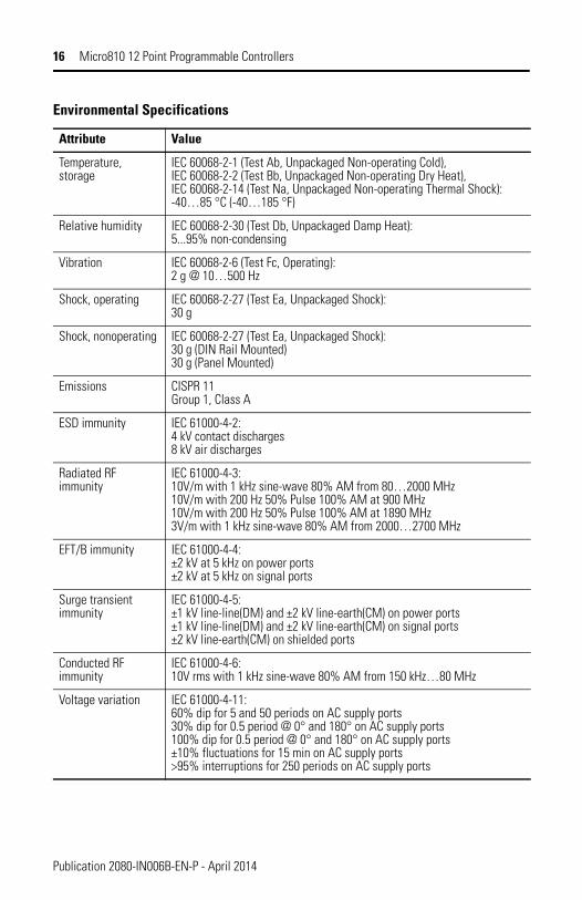
Environmental Specifications
Attribute Value
Temperature, operating
IEC 60068-2-1 (Test Ad, Operating Cold),IEC 60068-2-2 (Test Bd, Operating Dry Heat),IEC 60068-2-14 (Test Nb, Operating Thermal Shock):0…55 °C (32…131 °F)
Temperature, surrounding air, max
55 °C (131 °F)
Publication 2080-IN006B-EN-P - April 2014
16 Micro810 12 Point Programmable Controllers
Temperature, storage
IEC 60068-2-1 (Test Ab, Unpackaged Non-operating Cold),IEC 60068-2-2 (Test Bb, Unpackaged Non-operating Dry Heat),IEC 60068-2-14 (Test Na, Unpackaged Non-operating Thermal Shock):-40…85 °C (-40…185 °F)
Relative humidity IEC 60068-2-30 (Test Db, Unpackaged Damp Heat):5...95% non-condensing
Vibration IEC 60068-2-6 (Test Fc, Operating):2 g @ 10…500 Hz
Shock, operating IEC 60068-2-27 (Test Ea, Unpackaged Shock):30 g
Shock, nonoperating IEC 60068-2-27 (Test Ea, Unpackaged Shock):30 g (DIN Rail Mounted)30 g (Panel Mounted)
Emissions CISPR 11Group 1, Class A
ESD immunity IEC 61000-4-2:4 kV contact discharges8 kV air discharges
Radiated RF immunity
IEC 61000-4-3:10V/m with 1 kHz sine-wave 80% AM from 80…2000 MHz10V/m with 200 Hz 50% Pulse 100% AM at 900 MHz10V/m with 200 Hz 50% Pulse 100% AM at 1890 MHz3V/m with 1 kHz sine-wave 80% AM from 2000…2700 MHz
EFT/B immunity IEC 61000-4-4:±2 kV at 5 kHz on power ports±2 kV at 5 kHz on signal ports
Surge transient immunity
IEC 61000-4-5:±1 kV line-line(DM) and ±2 kV line-earth(CM) on power ports±1 kV line-line(DM) and ±2 kV line-earth(CM) on signal ports±2 kV line-earth(CM) on shielded ports
Conducted RF immunity
IEC 61000-4-6:10V rms with 1 kHz sine-wave 80% AM from 150 kHz…80 MHz
Voltage variation IEC 61000-4-11:60% dip for 5 and 50 periods on AC supply ports30% dip for 0.5 period @ 0° and 180° on AC supply ports100% dip for 0.5 period @ 0° and 180° on AC supply ports±10% fluctuations for 15 min on AC supply ports>95% interruptions for 250 periods on AC supply ports
Environmental Specifications
Attribute Value
Publication 2080-IN006B-EN-P - April 2014
Micro810 12 Point Programmable Controllers 17
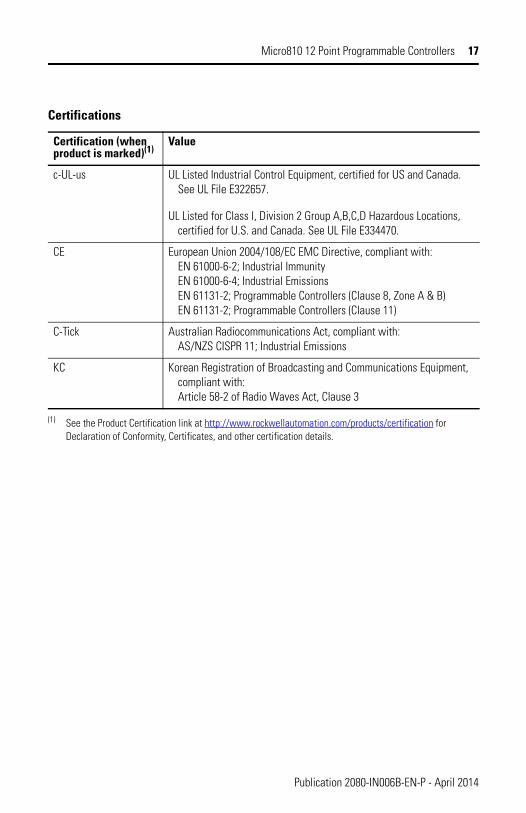
Certifications
Certification (when product is marked)(1)
(1) See the Product Certification link at http://www.rockwellautomation.com/products/certification for Declaration of Conformity, Certificates, and other certification details.
Value
c-UL-us UL Listed Industrial Control Equipment, certified for US and Canada. See UL File E322657.
UL Listed for Class I, Division 2 Group A,B,C,D Hazardous Locations, certified for U.S. and Canada. See UL File E334470.
CE European Union 2004/108/EC EMC Directive, compliant with:EN 61000-6-2; Industrial ImmunityEN 61000-6-4; Industrial EmissionsEN 61131-2; Programmable Controllers (Clause 8, Zone A & B)EN 61131-2; Programmable Controllers (Clause 11)
C-Tick Australian Radiocommunications Act, compliant with:AS/NZS CISPR 11; Industrial Emissions
KC Korean Registration of Broadcasting and Communications Equipment, compliant with:Article 58-2 of Radio Waves Act, Clause 3
Publication 2080-IN006B-EN-P - April 2014

18 Micro810 12 Point Programmable Controllers
Notes:
Publication 2080-IN006B-EN-P - April 2014

Micro810 12 Point Programmable Controllers 19
Notes:
Publication 2080-IN006B-EN-P - April 2014
Rockwell Automation Support
Rockwell Automation provides technical information on the Web to assist you in using its products. At http://support.rockwellautomation.com, you can find technical manuals, a knowledge base of FAQs, technical and application notes, sample code and links to software service packs, and a MySupport feature that you can customize to make the best use of these tools.For an additional level of technical phone support for installation, configuration and troubleshooting, we offer TechConnect support programs. For more information, contact your local distributor or Rockwell Automation representative, or visit http://support.rockwellautomation.com.Installation AssistanceIf you experience a problem within the first 24 hours of installation, please review the information that's contained in this manual. You can also contact a special Customer Support number for initial help in getting your product up and running.
New Product Satisfaction ReturnRockwell Automation tests all of its products to ensure that they are fully operational when shipped from the manufacturing facility. However, if your product is not functioning and needs to be returned, follow these procedures.
Allen-Bradley, Rockwell Automation, Micro800, Micro810, and TechConnect are trademarks of Rockwell Automation, Inc.
Trademarks not belonging to Rockwell Automation are property of their respective companies.
United States 1.440.646.3434Monday – Friday, 8 a.m. – 5 p.m. EST
Outside United States
Please contact your local Rockwell Automation representative for any technical support issues.
United States Contact your distributor. You must provide a Customer Support case number (call the phone number above to obtain one) to your distributor in order to complete the return process.
Outside United States
Please contact your local Rockwell Automation representative for the return procedure.
Publication 2080-IN006B-EN-P - April 2014 PN-244665Supersedes Publication 2080-IN006A-EN-P - September 2010 Copyright © 2014 Rockwell Automation, Inc. All rights reserved. Printed in Singapore.