Embed Size (px)
Citation preview

21-1
21
21. LIGHTS/METERS/SWITCHES
SYSTEM LOCATION································· 21-2
SERVICE INFORMATION ························· 21-3
HEADLIGHT··············································· 21-5
POSITION LIGHT ······································ 21-7
TURN SIGNAL ·········································· 21-7
TAIL/BRAKE LIGHT ·································· 21-9
LICENSE LIGHT······································· 21-10
COMBINATION METER·························· 21-11
SPEEDOMETER/VEHICLE SPEED SENSOR (VSS) ··········· 21-14
TACHOMETER ········································ 21-15
COOLANT TEMPERATURE INDICATOR/ECT SENSOR ·········································· 21-16
OIL PRESSURE INDICATOR/EOP SWITCH ·········································· 21-18
FUEL LEVEL SENSOR ···························· 21-20
IGNITION SWITCH ································· 21-20
HANDLEBAR SWITCHES ······················· 21-21
BRAKE LIGHT SWITCH ·························· 21-23
CLUTCH SWITCH ··································· 21-23
NEUTRAL SWITCH································· 21-24
SIDE STAND SWITCH ···························· 21-24
HORN ······················································ 21-26
TURN SIGNAL RELAY ··························· 21-27
HEADLIGHT RELAY································ 21-27

LIGHTS/METERS/SWITCHES
21-2
LIGHTS/METERS/SWITCHES
SYSTEM LOCATION
REAR BRAKE LIGHT SWITCH
ECT SENSOR
EOP SWITCH
IGNITION SWITCH
VS SENSOR
SIDE STAND SWITCH
NEUTRAL SWITCH
HORN
RIGHT HANDLEBAR SWITCH
RELAY BOX (HEADLIGHT RELAY)
LEFT HANDLEBAR SWITCH

LIGHTS/METERS/SWITCHES
21-3
SERVICE INFORMATIONGENERAL
• A halogen headlight bulb becomes very hot while the headlight is ON, and remain hot for a while after it is turned OFF.Be sure to let it cool down before servicing.
• Note the following when replacing the halogen headlight bulb.– Wear clean gloves while replacing the bulb. Do not put finger prints on the headlight bulb, as they may create hot
spots on the bulb and cause it to fail.– If you touch the bulb with your bare hands, clean it with a cloth moistened with denatured alcohol to prevent its early
failure.– Be sure to install the dust cover after replacing the bulb.
• Use an electric heating element to heat the water/coolant mixture for the ECT sensor inspection. Keep flammable mate-rials away from the electric heating element. Wear protective clothing, insulated gloves and eye protection.
• Check the battery condition before performing any inspection that requires proper battery voltage. • A continuity test can be made with the switches installed on the motorcycle. • The following color codes are used throughout this section.
SPECIFICATIONS
TORQUE VALUES
Bu = Blue G = Green Lg = Light green R = RedBl = Black Gr = Gray O = Orange W = WhiteBr = Brown Lb = Light blue P = Pink Y = Yellow
ITEM SPECIFICATIONS
Bulbs Headlight Hi 12 V – 55 WLo 12 V – 55 W
Position light 12 V – 5 W x 2Brake/tail light 12 V – 21/5 WTurn signal light 12 V – 21 W x 4Instrument light LEDTurn signal indicator LEDHigh beam indicator LEDOil pressure indicator LEDNeutral indicator LEDTemp. indicator LEDMalfunction indicator lamp (MIL) LEDImmobilizer indicator LEDABS indicator (CBF1000A) LED
Fuse Main fuse 30 APGM-FI/IGN fuse 20 ASub fuse 10 A x 3, 20 A x 2 ABS main fuse (CBF1000A) 10 AABS fail-safe relay fuse (CBF1000A) 30 AABS motor fuse (CBF1000A) 30 A
Tachometer peak voltage 10.5 V minimumECT sensor resistance 80 °C (176 °F) 2.1 – 2.6 kΩ
120 °C (248 °F) 0.65 – 0.73 kΩ
EOP switch 12 N·m (1.2 kgf·m, 9 lbf·ft) Apply sealant to the threads.EOP switch wire terminal bolt 2 N·m (0.2 kgf·m, 1.5 lbf·ft)Neutral switch 12 N·m (1.2 kgf·m, 9 lbf·ft)Ignition switch mounting one-way bolt 25 N·m (2.5 kgf·m, 18 lbf·ft)License light mounting nut 1.8 N·m (0.2 kgf·m, 1.3 lbf·ft)Horn mounting bolt 32 N·m (3.3 kgf·m, 24 lbf·ft)

LIGHTS/METERS/SWITCHES
21-4
TOOLS
Imrie diagnostic tester (model 625) orPeak voltage adaptor07HGJ-0020100
with commercially available digital multimeter (impedance 10 MΩ/DCV minimum)
Inspection test harness07GMJ-ML80100
Test probe07ZAJ-RDJA110

LIGHTS/METERS/SWITCHES
21-5
HEADLIGHTBULB REPLACEMENT
Remove the right and left front cowls (page 3-6).
Remove the dust cover.
Disconnect the headlight bulb connector.
Unhook the bulb retainer and remove the headlightbulb.
Align the bulb tabwith the groove in
the headlight case.
Install the new headlight bulb and hook the bulbretainer properly.
If you touch the bulb with your bare hands, clean itwith a cloth moistened with denatured alcohol toprevent early bulb failure.
Avoid touching the halogen headlight bulb. Fingerprints can create hot spots that cause a bulb tobreak.
DUST COVER
CONNECTOR
BULB
RETAINER
BULB
Align

LIGHTS/METERS/SWITCHES
21-6
Hook the bulb retainer properly.
Connect the headlight bulb connector.
Set the dust covertab in the cut-out ofthe headlight case.
Install the dust cover properly.
Install the right and left front cowls (page 3-6).
REMOVAL/INSTALLATION
Remove the front center cowl (page 3-7).
Remove the screws/washers, clamp and the head-light case.
Installation is in the reverse order of removal.
BULB
RETAINER
CONNECTOR
DUST COVER
TAB
SCREWS/WASHERS HEADLIGHT CASE
CLAMP

LIGHTS/METERS/SWITCHES
21-7
POSITION LIGHT
BULB REPLACEMENT
Remove the front center cowl (page 3-7).
Remove the bulb socket from the headlight case.
Do not turn the bulbwhile removing it.
Remove the bulb from the socket, and replace itwith new one.
Install the removed parts in the reverse order ofremoval.
TURN SIGNAL
FRONT TURN SIGNAL BULB REPLACEMENT
Remove the right and left front cowls (page 3-6).
Turn the bulb socket counterclockwise and removeit from the turn signal light case.
BULB SOCKET
BULB
SOCKET

LIGHTS/METERS/SWITCHES
21-8
Slightly press the bulb and turn it counterclockwise.
Replace the bulb with new one.
Install the removed parts in the reverse order.
REAR TURN SIGNAL BULB REPLACEMENT
Remove the screws and tail/brake light lens.
Remove the screw and turn signal light lens.
Slightly press the bulb and turn it counterclockwise.
Replace the bulb with new one.
Installation is in the reverse order of removal.
BULB
SCREWS
TAIL/BRAKE LIGHT LENS
TURN SIGNAL LIGHT LENS
SCREW
BULB

LIGHTS/METERS/SWITCHES
21-9
FRONT TURN SIGNAL LIGHT REMOVAL/INSTALLATION
Remove the right and left front cowls (page 3-6).
Remove the screws and turn signal light.
Route the turnsignal light wire
between the turnsignal light and
front cowl.
Install the turn signal light in the reverse order ofremoval.
TAIL/BRAKE LIGHT
BULB REPLACEMENT
Remove the screws and tail/brake light lens.
While pushing the bulb in, turn it counterclockwiseto remove and replace it with new one.
Installation is in the reverse order of removal.
SCREWS
TURN SIGNAL LIGHT
TURN SIGNAL LIGHT WIRE
SCREWS
TAIL/BRAKE LIGHT LENS
BULB
LIGHTS/METERS/SWITCHES
21-10
TAIL/BRAKE LIGHT UNIT REMOVAL/INSTALLATION
Remove the rear fender (page 3-10).
Remove the screws, bolts and tail/brake light unit.
Install the removed parts in the reverse order ofremoval.
LICENSE LIGHT
BULB REPLACEMENT
Remove the screws and license light cover.
Do not turn the bulbwhile removing it.
Pull out the bulb from the socket and replace it withnew one.
Install the license light cover and tighten the screwssecurely.
REMOVAL/INSTALLATION
Remove the screws, license light cover, packing andbulb.Remove the nuts and collars from the inside of therear fender.Remove the bulb socket from the license light base.
Install the license light in the reverse order ofremoval.
TAIL/BRAKE LIGHT UNIT SCREWS
BOLTS
SCREWS
COVER
SOCKET
BULB
TORQUE:
License light mounting nut:
1.8 N·m (0.2 kgf·m, 1.3 lbf·ft)
NUTS/COLLARS
BASE
COVER
PACKING
SCREWS
BULB

LIGHTS/METERS/SWITCHES
21-11
COMBINATION METER
REMOVAL/INSTALLATION
Remove the front center cowl (page 3-7).
Remove the mounting bolts and the combinationmeter from the bracket.
Install the combination meter in the reverse order ofremoval.
DISASSEMBLY
Remove the collars and grommets.
Remove the screws, combination meter lens andreflecting plate.
Remove the screws/washers and tapping screws.
Remove the screws and combination meter circuitboard from the lower case.
BOLTS
COMBINATION METER
SCREWS
COLLAR/GROMMETSLENS
REFLECTING PLATE
TAPPING SCREWSSCREWS/WASHERS
LOWER CASE
CIRCUIT BOARD
SCREWS
LOWER CASE

LIGHTS/METERS/SWITCHES
21-12
ASSEMBLY
Assembly is in the reverse order of disassembly.
POWER/GROUND LINES INSPECTION
Remove the front center cowl (page 3-7).
Remove the combination meter connector dustcover.Check the following with the 16P connector con-nected.
Power input line
Measure the voltage between the Black/brown wireterminal (+) and body ground (–).There should be battery voltage with the ignitionswitch ON.If there is no voltage, check the sub-fuse (10 A) andan open circuit in Brown/white wire.
CIRCUIT BOARD
COMBINATION METER LENS
REFLECTING PLATELOWER CASE
COLLARS
GROMMETS
16P CONNECTOR
DUST COVER
Black/blown (+)
Viewed from harness side of the 16P connector:
LIGHTS/METERS/SWITCHES
21-13
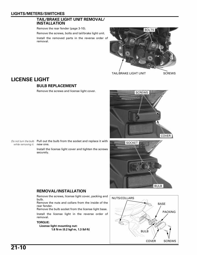
Back-up voltage line
Measure the voltage between the Red/green wireterminal (+) and body ground (–).There should be battery voltage at all times.If there is no voltage, check the sub-fuse (10 A) andan open circuit in Red/green wire.
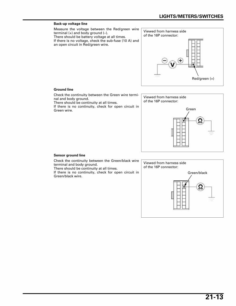
Ground line
Check the continuity between the Green wire termi-nal and body ground.There should be continuity at all times.If there is no continuity, check for open circuit inGreen wire.
Sensor ground line
Check the continuity between the Green/black wireterminal and body ground.There should be continuity at all times.If there is no continuity, check for open circuit inGreen/black wire.
Red/green (+)
Viewed from harness side of the 16P connector:
Green
Viewed from harness side of the 16P connector:
Green/black
Viewed from harness side of the 16P connector:

LIGHTS/METERS/SWITCHES
21-14
SPEEDOMETER/VEHICLE SPEED SENSOR (VSS)
SYSTEM INSPECTION
Check that the neutral and oil pressure indicatorsfunction properly.
• If they do not function, perform the power andground line inspection of the combination meter(page 21-12).
• If they function, remove the dust cover and dis-connect the combination meter 16P (Black) con-nector. Shift the transmission into neutral andturn the ignition switch ON.Measure the voltage between the Pink/green (+)and Green/black (–) wire terminals of the wireharness side connector.Slowly turn the rear wheel by hand.There should be 0 to 5 V pulse voltage.
– If pulse voltage appears, replace the combinationmeter printed circuit board (page 21-11).
– If pulse voltage does not appear, check for openor short circuit in the Pink/green and Green/blackwires.If the wire are OK, check the VSS (page 21-14).
VEHICLE SPEED SENSOR (VSS) INSPECTION
Remove the air cleaner housing (page 6-60).
Disconnect the VSS 3P (Natural) connector.Measure the voltage between the Yellow/red (+) andGreen/black (–) wire terminals at the harness side 3Pconnector.
There should be battery voltage with the ignitionswitch ON.
If there is no voltage, check for open circuit inrelated wires.If there is voltage, check the VSS as follows.
Support the motorcycle securely using a safetystand or hoist, and raise the rear wheel off theground.
Connect the inspection adaptor to the sensor 3Pconnectors.
Connect the Positive (+) and negative (–) cables tothe battery.Measure the voltage between the Red clip (+) andWhite clip (–).
Shift the transmission into neutral and turn the igni-tion switch ON.Slowly turn the rear wheel by hand.There should be 0 to 5 V pulse voltage.
If the pulse voltage does not appear, replace theVSS (page 21-15).
16P CONNECTOR
DUST COVER
Viewed from wire side:
P/G (+)
G/Bl (–)
CONNECTION: Yellow/red (+) – Green/black (–)
STANDARD: Battery voltage
3P (NATURAL) CONNECTOR
G/Bl (–)
Y/R (+)
Wire side of male terminals:
TOOL:
Inspection test harness 07GMJ-ML80100
CONNECTION: Red clip (+) – White clip (–)
STANDARD: Repeat 0 to 5V
INSPECTION ADAPTOR
RED CLIP (+) (Pink WIRE)
WHITE CLIP (–) (Green WIRE)

LIGHTS/METERS/SWITCHES
21-15
REMOVAL/INSTALLATION
Remove the air cleaner housing (page 6-60).
Remove the VSS 3P (Natural) connector from thestay and disconnect the connector.
Remove the bolt, stay and the VSS.
Check the condition of the O-ring, replace it if neces-sary.
Install the VSS in the reverse order of removal.
Install the air cleaner housing (page 6-67).
TACHOMETER
SYSTEM INSPECTION
Check that the neutral and oil pressure indicatorsfunction properly.
• If they do not function, perform the power andground line inspection of the combination meter(page 21-12).
Remove the front center cowl (page 3-7).
Remove the dust cover and check for loose or poorcontact terminals at the combination meter 16P(Black) connector.
3P (Natural) CONNECTOR
BOLT/STAY
VSS
VSS
O-RING
16P CONNECTOR
DUST COVER

LIGHTS/METERS/SWITCHES
21-16
Connect the peak voltage adaptor or Imrie diagnos-tic tester probe to the tachometer Yellow/green ter-minal and ground.
Start the engine and measure the tachometer inputpeak voltage.
If the peak voltage is normal, replace the combina-tion meter printed circuit board (page 21-11).If the measured value is below 10.5 V, replace theECM (page 6-82).
If the value is 0 V, check for continuity between thecombination meter 16P (Black) connector and ECM33P (Light gray) connector Yellow/green terminals.
If there is no continuity, check the wire harness foran open circuit.If there is continuity, replace the ECM (page 6-82).
COOLANT TEMPERATURE INDICATOR/ECT SENSOR
SYSTEM INSPECTION
Indicator stays lit while the engine is running under normal operating temperature
Lift and support the fuel tank (page 4-5).
Disconnect the crankcase breather hose.Remove the thermostat case mounting bolt.
TOOLS:
Imrie diagnostic tester (model 625) or
Peak voltage adaptor 07HGJ-0020100
with commercially available digital multimeter(impedance 10 MΩ/DCV minimum)
CONNECTION: Yellow/green (+) – body ground (–)
PEAK VOLTAGE: 10.5 V minimum
16P (Black) CONNECTOR (Viewed from harness side)
Yellow/green
TOOLS:
Test probe 07ZAJ-RDJA110
33P (Light gray) CONNECTOR (Wire side of female terminals)
16P (Black) CONNECTOR (Viewed from harness side)
Yellow/green
BOLT
BREATHER HOSE

LIGHTS/METERS/SWITCHES
21-17
Disconnect the ECT sensor 3P (Gray) connector.
Check for continuity between the Green/blue termi-nal and ground.
If there is continuity, check for short circuit in theGreen/blue wire.If there is no continuity, replace the ECT sensor(page 6-79).
SENSOR INSPECTION
Disconnect the 3P (Gray) connector and remove theECT sensor from the thermostat housing (page 6-79).
ECT SENSOR
3P (Gray) CONNECTOR
3P (Gray) CONNECTOR(Wire side of male terminals)
Green/blue
ECT SENSOR
3P (Gray) CONNECTOR

LIGHTS/METERS/SWITCHES
21-18
Suspend the ECT sensor in a pan of coolant (50 – 50mixture) on an electric heating element and mea-sure the resistance through the ECT sensor terminal(Green/blue) and sensor body as the coolant heatsup.
• Soak the ECT sensor in coolant up to its threadswith at least 40 mm (1.6 in) from the bottom ofthe pan to the bottom of the sensor.
• Keep the temperature constant for 3 minutesbefore testing. A sudden change of temperaturewill result in incorrect readings. Do not let thethermometer or ECT sensor touch the pan.
Replace the sensor if it is out of specification bymore than 10% at any temperature listed.
OIL PRESSURE INDICATOR/EOP SWITCH
INSPECTION
Indicator does not light with the ignition switchturned to "ON"
Check that the neutral and ABS (CBF1000A) indica-tors function properly.If they do not function properly, check the powerinput line of the combination meter (page 21-12).
Remove the rubber cap, and disconnect the oil pres-sure switch wire by removing the terminal bolt.Ground the wire terminal to the engine with ajumper wire.Turn the ignition switch to "ON" and check the oilpressure indicator.
• If the indicator lights, replace the EOP switch. • If the indicator does not light, check for loose or
poor connections of the engine sub-harness 8P(Gray) connector, or an open circuit in the Blue/red wire.
Indicator stays lit while the engine is running
Remove the rubber cap, and disconnect the EOPswitch wire by removing the terminal bolt.Check for continuity between the wire terminal andground.
• If there is continuity, check for short circuit in theBlue/red wire.
• If the there is no continuity, check the oil pres-sure (page 5-5). If the oil pressure is normal,replace the EOP switch.
Temperature 80°C (68°F) 120°C (248°F)Resistance 2.1 – 2.6 kΩ 0.65 – 0.73 kΩ
ECT SENSOR
ECT SENSOR TERMINAL
EOP SWITCH
TERMINAL BOLT
OIL PRESSURE INDICATOR

LIGHTS/METERS/SWITCHES
21-19
REMOVAL/INSTALLATION
Drain the engine oil (page 4-16).
Release the EOP switch wire from the clamp.Remove the rubber cap and terminal bolt, then dis-connect the wire terminal. Remove the EOP switch while holding switch base.
Apply sealant to the EOP switch threads as shown.
Install the EOP switch onto the switch base, andtighten the EOP switch to the specified torque whileholding the switch base.
Connect the EOP switch wire to the switch andtighten the terminal bolt to the specified torque.
Secure the EOP switch wire with the clamp andinstall the rubber cap.
Fill the crankcase with the recommended engine oil(page 4-16).
RUBBER CAP TERMINAL BOLT
EOP SWITCH
CLAMP
Do not apply sealant to the thread head 3 – 4 mm (0.1 – 0.2 in).
TORQUE: 12 N·m (1.2 kgf·m, 9 lbf·ft)
EOP SWITCH SWITCH BASE
TORQUE: 2 N·m (0.2 kgf·m, 1.5 lbf·ft)
Refer to "Cable &Harness Routing"
for EOP switch wireclamp (page 1-23).
RUBBER CAP TERMINAL BOLT
EOP SWITCH
CLAMP

LIGHTS/METERS/SWITCHES
21-20
FUEL LEVEL SENSOR
INSPECTION
Remove the fuel pump unit (page 6-55).
Connect the ohmmeter to the fuel level sensor Red/black and Black/white terminals.
Inspect the resistance of the float at the top and bot-tom positions.
Connect the fuel pump unit 3P (Black) connector tothe main wire harness.Move the float from bottom (empty) to top (full)positions to check the fuel meter needle indication.
Turn the ignition switch ON.If the fuel meter needle does not indicate properly,check for open or short circuit in wire harness.If the wire harness is good, replace the combinationmeter printed circuit board with new one (page 21-11).
IGNITION SWITCHINSPECTION
Remove the front center cowl (page 3-7).
Disconnect the ignition switch 4P (Natural) connec-tor.Check for continuity between the wire terminals ofthe ignition switch connector in each switch posi-tion.Continuity should exist between the color codedwires as follow:
IGNITION SWITCH CONTINUITY:
FULL EMPTYResistance 4 – 10 Ω 90 – 100 Ω
FUEL PUMP UNIT
FULL
EMPTY
FULL
EMPTY
4P (Natural) CONNECTOR

LIGHTS/METERS/SWITCHES
21-21
REMOVAL/INSTALLATION
Remove the top bridge (page 14-30).Remove the immobilizer receiver (page 22-15).
Remove the mounting bolts and ignition switch.
Install the ignition switch to the top bridge.Tighten the new ignition switch mounting bolts tothe specified torque.
Install the removed parts in the reverse order ofremoval.
HANDLEBAR SWITCHES
RIGHT HANDLEBAR SWITCH
Remove the front center cowl (page 3-7).
Disconnect the right handlebar switch 9P (Brown)and 2P (Natural) connectors.
Check for continuity between the wire terminals ofthe handlebar switch connector.
Continuity should exist between the color codedwire terminals as follows:
RIGHT HANDLEBAR SWITCH CONTINUITY:
TORQUE: 25 N·m (2.5 kgf·m, 18 lbf·ft)
BOLTS
IGNITION SWITCH
2P CONNECTOR9P (Brown) CONNECTOR
ENGINE STOP SWITCH
STARTER SWITCHHAZARD SWITCH

LIGHTS/METERS/SWITCHES
21-22
LEFT HANDLEBAR SWITCH
Remove the front center cowl (page 3-7).
Disconnect the left handlebar switch 4P (Black) and6P (Blue) connectors.
Check for continuity between the wire terminals ofthe handlebar switch connector.
Continuity should exist between the color codedwire terminals as follows:
LEFT HANDLEBAR CONTINUITY:
6P (Blue) CONNECTOR
4P (Black) CONNECTOR
TURN SIGNAL SWITCH
DIMMER SWITCH
HORN SWITCH
PASSING SWITCH

LIGHTS/METERS/SWITCHES
21-23
BRAKE LIGHT SWITCH
FRONT
Disconnect the front brake light switch connectorsand check for continuity between the terminals.There should be continuity with the brake leverapplied, and there should be no continuity with thebrake lever is released.
REAR
Remove the wire band.Disconnect the rear brake light switch 2P (Black)connector.
Check for continuity between the terminals.There should be continuity with the brake pedalapplied, and there should be no continuity with thebrake pedal is released.
CLUTCH SWITCHDisconnect the clutch switch connectors.
There should be continuity with the clutch leverapplied, and there should be no continuity when theclutch lever is released.
BRAKE LIGHT SWITCH
2P (Black) CONNECTOR
WIRE BAND
2P (Black) CONNECTOR
CLUTCH SWITCH

LIGHTS/METERS/SWITCHES
21-24
NEUTRAL SWITCH
INSPECTION
Lift and support the fuel tank (page 4-5).
Disconnect the engine sub-harness 8P (Gray) con-nector.Shift the transmission into neutral and check forcontinuity between the Light green wire terminaland body ground.
There should be continuity with the transmission inneutral, and no continuity when the transmission isin gear.
REMOVAL/INSTALLATION
Remove the engine from the frame (page 8-4).
Remove the rubber cap.Remove the terminal nut and disconnect the neutralswitch wire.Remove the neutral switch and sealing washer.
Installation is in the reverse order of removal.
SIDE STAND SWITCH
INSPECTION
Remove the following:
– Left side cover (page 3-4)– Left rear cowl (page 3-8)
Disconnect the side stand switch 2P (Green) connec-tor.
Check for continuity between the wire terminals ofthe side stand switch 2P (Green) connector.
Continuity should exist only when the side stand isup.
8P (Gray) CONNECTOR
Replace the sealingwasher with new
one. TORQUE:
Neutral switch:
12 N·m (1.2 kgf·m, 9 lbf·ft)
NEUTRAL SWITCH
RUBBER CAP
NUT
SEALING WASHER
2P (Green) CONNECTOR

LIGHTS/METERS/SWITCHES
21-25
REMOVAL
Remove the following:
– Left side cover (page 3-4)– Left rear cowl (page 3-8)
Remove the wire band and disconnect the sidestand switch 2P (Green) connector.
Remove the bolt and side stand switch.
INSTALLATION
Route the side stand switch wire properly (page 1-23).
Install the side stand switch by aligning the switchpin with the side stand hole and switch groove withthe return spring holding pin.
Secure the side stand switch with a new bolt.
WIRE BAND
2P (Green) CONNECTOR
BOLTSIDE STAND SWITCH
SIDE STAND SWITCH
CUT-OUT
Align
BOLTSIDE STAND SWITCH

LIGHTS/METERS/SWITCHES
21-26
Connect the 2P (Green) connector.Secure the side stand switch wire with the wireband.
Install the following:
– Left rear cowl (page 3-9)– Left side cover (page 3-4)
HORNDisconnect the wire connectors from the horn.Connect the 12 V battery to the horn terminaldirectly.The horn is normal if it sounds when the 12 V bat-tery is connected across the horn terminals.
REMOVAL/INSTALLATION
Disconnect the horn wire connectors.
Remove the mounting bolt and horn.
Installation is in the reverse order of removal.
WIRE BAND
2P (Green) CONNECTOR
HORN
TORQUE: 32 N·m (3.3 kgf·m, 24 lbf·ft)
CONNECTORS
HORN
BOLT

LIGHTS/METERS/SWITCHES
21-27
TURN SIGNAL RELAYINSPECTION
1. Related Circuit Inspection
Check the following:– Burned bulb or non-specified wattage– Blown fuse– Ignition switch and turn signal switch func-
tion– Loose connectors
Check for the above items.
Are the above items in good condition?
NO – Replace or repair the malfunctionpart(s)
YES – GO TO STEP 2.
2. Turn Signal Circuit Inspection
Remove the right rear cowl (page 3-8).
Disconnect the turn signal 4P connector andshort the Gray and White/green terminals of thewire harness side connector with a jumper wire.Turn the ignition switch ON and check the turnsignal light by turning the turn signal switch on.
Does the light come on?
YES – GO TO STEP 3.
NO – Open circuit in related wires
3. Ground Line Inspection
Check the continuity between the 4P connectorGreen terminal and ground.
Is there continuity?
YES – • Faulty turn signal relay • Loose or poor contact of the connec-
tor terminals
NO – Open circuit in Green wire
HEADLIGHT RELAY
INSPECTION
Remove the right rear cowl (page 3-8).
Remove the relay box from the bracket.
4P CONNECTOR
TURN SIGNAL RELAY
RELAY BOX

LIGHTS/METERS/SWITCHES
21-28
Release the retainers and remove the relay connec-tor (Blue) from the relay box.
Remove the headlight relay from the relay connec-tor (Blue).
Connect the ohmmeter to the following headlightrelay terminals.
Connect the 12 V battery to the following headlightrelay terminals.
There should be continuity only when the 12 V bat-tery is connected.If there is no continuity when the 12 V battery isconnected, replace the headlight relay.
RELAY CONNECTOR (Blue)
HEADLIGHT RELAY
CONNECTION: A (Black/red) – B (Black/blue)
CONNECTION: C (Blue) – D (Green)
HEADLIGHT RELAY BATTERY
A C
DB