Embed Size (px)
Citation preview
Standard Technology
Title: Earthing and Lightning Protection Standard
Unique Identifier: 240-56356396
Alternative Reference Number: 474-085
Area of Applicability: Engineering
Documentation Type: Standard
Revision: 1
Total Pages: 45
Next Review Date: November 2015
Disclosure Classification: CONTROLLED DISCLOSURE
Compiled by Approved by Authorised by
………………………………….. ………………………………….. …………………………………..
T Joni
GTE: Senior Technician
L P Malaza
Electrical Plant Engineering Manager
R P Madiba
EC&I Senior Engineering Manager
Date: …………………………… Date: …………………………… Date: ……………………………
Approved by TDAC
…………………………………..
D. Odendaal
TDAC Chairperson
Date: ……………………………
CONTROLLED DISCLOSURE
When downloaded from the EDMS, this document is uncontrolled and the responsibility rests with the user to ensure it is in line with the authorised version on the system.
Earthing and Lightning Protection Standard
Unique Identifier: 240-56356396
Revision: 1
Page: 2 of 45
CONTENTS
Page
1. INTRODUCTION ...................................................................................................................................................... 5
2. SUPPORTING CLAUSES ........................................................................................................................................ 5
2.1 SCOPE .............................................................................................................................................................. 5 2.1.1 Purpose ..................................................................................................................................................... 5 2.1.2 Applicability................................................................................................................................................ 5
2.2 NORMATIVE/INFORMATIVE REFERENCES .................................................................................................. 5 2.2.1 Normative .................................................................................................................................................. 5
2.3 DEFINITIONS .................................................................................................................................................... 6 2.3.1 Classification ............................................................................................................................................. 7
2.4 ABBREVIATIONS .............................................................................................................................................. 7 2.5 ROLES AND RESPONSIBILITIES .................................................................................................................... 7 2.6 PROCESS FOR MONITORING ........................................................................................................................ 7 2.7 RELATED/SUPPORTING DOCUMENTS ......................................................................................................... 7
3. EARTHING AND LIGHTNING PROTECTION STANDARD ................................................................................... 8
3.1 ERECTION ........................................................................................................................................................ 8 3.1.1 Requirement for Specifications ................................................................................................................. 8 3.1.2 Copper Theft.............................................................................................................................................. 8 3.1.3 Excavation Work ....................................................................................................................................... 8 3.1.4 Corrosion ................................................................................................................................................... 8 3.1.5 Prevention Techniques .............................................................................................................................. 8 3.1.6 Routine Maintenance ................................................................................................................................ 8
3.2 DESIGN CRITERIA, GUIDELINES AND PRINCIPLES .................................................................................... 9 3.2.1 Supplier Specifications .............................................................................................................................. 9 3.2.2 Earthing and Lightning Protection Principles ............................................................................................ 9
3.2.2.1 Types of Interference ........................................................................................................................ 9 3.2.2.2 Common Impedance Coupling ........................................................................................................ 10 3.2.2.3 Capacitive Coupling ........................................................................................................................ 10 3.2.2.4 Inductive Coupling ........................................................................................................................... 10 3.2.2.5 Electromagnetic Coupling ............................................................................................................... 11
3.2.3 Zoning Concept ....................................................................................................................................... 12 3.2.3.1 The different zones that are used for shielding are as shown in figure 1. ...................................... 12 3.2.3.2 PLC cable entering from LPZ0 to the highly protected zone LPZ3 ................................................. 13 3.2.3.3 Minimizing of surface current by single entry point of cables ......................................................... 14
3.3 MATERIALS USED ......................................................................................................................................... 14 3.4 BRAZING OF COPPER .................................................................................................................................. 15
3.4.1 Filler Metals and Fluxes .......................................................................................................................... 15 3.4.2 Types of Joints ........................................................................................................................................ 15 3.4.3 Preparations for Brazing .......................................................................................................................... 16 3.4.4 Brazing .................................................................................................................................................... 16
3.5 CONDUCTORS ............................................................................................................................................... 17 3.5.1 Fault Levels ............................................................................................................................................. 17 3.5.2 Design Basis............................................................................................................................................ 17 3.5.3 Conductor Sizes ...................................................................................................................................... 17 3.5.4 Earthing Tails........................................................................................................................................... 18 3.5.5 Connections............................................................................................................................................. 18
3.6 INSTALLATION ............................................................................................................................................... 18 3.6.1 Earthing with Cable Racking ................................................................................................................... 18 3.6.2 Power and Control Cables 600/1000 V ................................................................................................... 18
3.6.2.2 Supply Cabling ................................................................................................................................ 19 3.6.2.3 Motor Cables ................................................................................................................................... 19
3.6.3 Process Control (and some protection) Cables ...................................................................................... 19 3.6.3.1 Signal Cables .................................................................................................................................. 19
CONTROLLED DISCLOSURE
When downloaded from the EDMS, this document is uncontrolled and the responsibility rests with the user to ensure it is in line with the authorised version on the system.
Earthing and Lightning Protection Standard
Unique Identifier: 240-56356396
Revision: 1
Page: 3 of 45
3.6.3.2 Interfacing problem of systems with dissimilar grounding .............................................................. 20 3.6.4 Control Cable Shielding ........................................................................................................................... 20
3.6.4.1 Analogue and Low Voltage Digital I/O Signals ............................................................................... 20 3.6.4.2 Serial Communication ..................................................................................................................... 20 3.6.4.3 Shield Connection ........................................................................................................................... 21
3.7 CABLE JUNCTION BOXES ............................................................................................................................ 21 3.7.1 Computer and Computer Room Earthing ................................................................................................ 21 3.7.2 Earth Mats under foundations and floors ................................................................................................ 21 3.7.3 Structural Steelwork ................................................................................................................................ 21 3.7.4 Reinforcing Steel in Concrete Columns .................................................................................................. 22 3.7.5 Metal Roofs and Cladding ....................................................................................................................... 22 3.7.6 Fire Protection ......................................................................................................................................... 22 3.7.7 Ancillary Buildings ................................................................................................................................... 23 3.7.8 Process Control and Electronic Equipment ............................................................................................. 23
3.7.8.1 Grounding of Junction Boxes .......................................................................................................... 23 3.7.8.2 Cable Support Structures and Cabling ........................................................................................... 23 3.7.8.3 Earthing and handling of Screens ................................................................................................... 23
3.8 ELECTRICAL PLANT PROTECTION EQUIPMENT ...................................................................................... 23 3.9 NEUTRAL AND RESISTANCE EARTHING ................................................................................................... 24
3.9.1 The Main Electrical Systems are earthed as per the following table: ..................................................... 24 3.9.2 Generator Earthing .................................................................................................................................. 24
3.9.2.1 Generator Earthing .......................................................................................................................... 25 3.9.2.2 Generator Transformer Earthing ..................................................................................................... 25 3.9.2.3 Generator Transformer Earthing ..................................................................................................... 26
3.9.3 Generator Export System Earthing (busbars, breaker and earth switch) ............................................... 26 3.9.4 Unit Transformer Earthing ....................................................................................................................... 27
3.9.4.1 Unit Transformer Earthing ............................................................................................................... 27 3.9.5 Service Transformer Earthing ................................................................................................................. 27 3.9.6 Station Transformer Earthing .................................................................................................................. 28
3.9.6.1 Station Transformer Earthing Arrangement .................................................................................... 28 3.10 FAULT CURRENT RATINGS ....................................................................................................................... 28
3.10.1 Generator Phase Isolated Busbars ....................................................................................................... 28 3.10.2 Generator Circuit Breaker ..................................................................................................................... 28 3.10.3 Generator Transformer .......................................................................................................................... 29 3.10.4 Unit Transformers .................................................................................................................................. 29 3.10.5 Service Transformers ............................................................................................................................ 29 3.10.6 Station Transformer ............................................................................................................................... 29
3.11 GENERATOR AND UNIT TRANSFORMERS .............................................................................................. 29 3.11.1 Generator Export System (busbars, earth switch and circuit breaker) ................................................. 29 3.11.2 Transformers ......................................................................................................................................... 30 3.11.3 MV and LV Switchboards, Control Panels and Cubicles ...................................................................... 30
3.12 ELECTRIC MOTORS AND LOCAL CONTROL STATIONS ......................................................................... 30 3.12.2 Boiler Feed Water Pumps ..................................................................................................................... 30 3.12.3 Air Cooled Condensers ......................................................................................................................... 30
3.13 AUXILIARY BAY CABLE TUNNELS ............................................................................................................. 31 3.14 HIGH MASTS FOR AREA LIGHTING ........................................................................................................... 31
3.14.1 Mini-Substations for perimeter fence lighting and fence earthing ......................................................... 31 3.14.2 Construction Ring .................................................................................................................................. 31 3.14.3 Station and Unit Diesel Generators ....................................................................................................... 31 3.14.4 Chimneys ............................................................................................................................................... 31 3.14.5 Flue-Ducts and Support Structures ....................................................................................................... 32 3.14.6 All Vessels ............................................................................................................................................. 32 3.14.7 Conveyors ............................................................................................................................................. 32 3.14.8 Equipment Moving on Rails................................................................................................................... 32
3.15 EARTHING OF RAILS ................................................................................................................................... 32 3.15.1 Longitudinal Bonding ............................................................................................................................. 32 3.15.2 Cross Bonding ....................................................................................................................................... 33
CONTROLLED DISCLOSURE
When downloaded from the EDMS, this document is uncontrolled and the responsibility rests with the user to ensure it is in line with the authorised version on the system.
Earthing and Lightning Protection Standard
Unique Identifier: 240-56356396
Revision: 1
Page: 4 of 45
3.15.3 Connections to Earth ............................................................................................................................. 33 3.15.4 Earthing of Land Junction Boxes .......................................................................................................... 33 3.15.5 Earthing of Shiftable (ash) Conveyor Modules ...................................................................................... 33 3.15.6 Earthing of Stacker/Reclaimer, Tripper Cars and Stackers to Rails ..................................................... 34 3.15.7 Earthing of on-board Equipment ........................................................................................................... 34 3.15.8 Cross Bonding of Ash Stackers and Link Conveyors to Tripper Cars .................................................. 34 3.15.9 HV Yard ................................................................................................................................................. 34
3.16 TESTING AND MAINTENANCE ................................................................................................................... 34 3.16.1 VISUAL INSPECTIONS ........................................................................................................................ 35 3.16.2 EARTHING TRIANGLES ...................................................................................................................... 35 3.16.3 TEST AND MEASUREMENTS ............................................................................................................. 36 3.16.4 Earth Resistance Measurements .......................................................................................................... 36 3.16.5 Continuity Measurements ...................................................................................................................... 36
3.17 DOCUMENTATION AND RECORDS ........................................................................................................... 37 3.17.1 Design Standard .................................................................................................................................... 37 3.17.2 Drawings ................................................................................................................................................ 37 3.17.3 Maintenance Plan and PM’s (planned maintenance activities)............................................................. 37 3.17.4 Test reports ........................................................................................................................................... 37 3.17.5 Visual Check Reports ............................................................................................................................ 37 3.17.6 Copper Theft Reports ............................................................................................................................ 38
3.18 DRAWINGS AND SPECIFICATIONS ........................................................................................................... 38 3.18.1 Drawings ................................................................................................................................................ 38
APPENDICES ............................................................................................................................................................ 38
1. CONTINUITY MEASUREMENTS .......................................................................................................................... 41
2. INSPECTIONS ....................................................................................................................................................... 41
3. EARTHING SYSTEM CHECKLIST ....................................................................................................................... 42
4. SOIL SAMPLE PROCEDURE ............................................................................................................................... 43
APPENDIX D: SCHEDULED MAINTENANCE ACTIVITIES ................................................................................... 44
5. AUTHORISATION .................................................................................................................................................. 45
6. REVISIONS ............................................................................................................................................................ 45
7. DEVELOPMENT TEAM ......................................................................................................................................... 45
8. ACKNOWLEDGEMENTS ...................................................................................................................................... 45
FIGURES
Figure 1: Power Station typical Zone Definition .................................................................................................... 12 Figure 2: PLC cable entering from LPZ0 to the highly protected zone LPZ3 ..................................................... 13 Figure 3: Minimizing of surface current by single entry point of cables ............................................................ 14 Figure 4: Generator Earthing ................................................................................................................................... 25 Figure 5: Generator Transformer Earthing ............................................................................................................ 26 Figure 6: Unit Transformer Earthing ....................................................................................................................... 27 Figure 7: Station Transformer Earthing Arrangement .......................................................................................... 28
TABLES
Table 1: Fault Levels ................................................................................................................................................ 17 Table 2: Neutral and Resistance Earthing.............................................................................................................. 24 Table 3: Drawings ..................................................................................................................................................... 38
CONTROLLED DISCLOSURE
When downloaded from the EDMS, this document is uncontrolled and the responsibility rests with the user to ensure it is in line with the authorised version on the system.
Earthing and Lightning Protection Standard
Unique Identifier: 240-56356396
Revision: 1
Page: 5 of 45
1. INTRODUCTION
a. The primary goal of earthing systems is to ensure the safety of personnel and to prevent damage to installations. The secondary goal (in systems with sensitive equipment) is to serve as a common voltage reference and to contribute to the mitigation of disturbances.
b. The problems associated with earthing and lightning protection are complex, there will always be problems associated with it throughout the power station operating life, and it is therefore of utmost importance to put measures in place to take care of them to ensure that the plant is protected at all times.
2. SUPPORTING CLAUSES
2.1 SCOPE
This document defines the requirements for the design, supply, installation and testing with respect to Power station earthing and lightning protection. Design guidelines, application information and maintenance and test plans are provided.
2.1.1 Purpose
None
2.1.2 Applicability
This document shall apply throughout Eskom Holdings Limited Divisions.
2.2 NORMATIVE/INFORMATIVE REFERENCES
Parties using this document shall apply the most recent edition of the documents listed in the following paragraphs.
2.2.1 Normative
REFERENCE DESCRIPTION
NRS 042 Guide for the protection of electronic equipment against damaging transients
IEC 61000-4-2 Electromagnetic compatibility (EMC) – Part 4: Electrostatic discharge immunity test – Basic EMC Publication.
IEC 61000-4-4 Electromagnetic compatibility (EMC) – Part 4: Testing and measurement techniques – Section 4: Electrical fast transient/burst immunity test – Basic EMC publication.
IEC 61024-1 Protection of structures against lightning: Part 1: General principles
lEC 61024-1-1 Protection of structures against lightning: Part 1; General principles: Section 1: Guide A - Selection of protection levels for lightning protection systems
IEC 61643-1 Surge protective devices connected to low-voltage power distribution systems Part1: Performance requirements and testing methods
IEC 61662 Assessment of the risk of damage due to lightning (including amendments)
IEEE 665 IEEE Guide for Generating Station Grounding
IEEE 1050 IEEE Guide for Instrumentation and Control Equipment Grounding in Generating Stations
CONTROLLED DISCLOSURE
When downloaded from the EDMS, this document is uncontrolled and the responsibility rests with the user to ensure it is in line with the authorised version on the system.
Earthing and Lightning Protection Standard
Unique Identifier: 240-56356396
Revision: 1
Page: 6 of 45
SANS 121 Hot dip galvanized coatings on fabricated iron and steel articles – specifications and test methods
SANS 1063 Earth rods, couplers and connections
SANS 1213 Mechanical cable glands
SANS 10142-1 Part 1-The wiring of premises
SANS 10313 The protection of structures against lightning
SANS 62305-1 Protection against Lightning: Part 1: General Principles
SANS 62305-2 Protection against Lightning: Part 2: Risk Management
SANS 62305-3 Protection against Lightning: Part 3: Physical damage to structures and life hazard
SANS 62305-4 Protection against Lightning: Part 4: Electrical and electronic systems within structures
2.3 DEFINITIONS
Definition Description
Bonding The connecting together of exposed conductive parts of apparatus, systems and installations to ensure that they are at the same potential.
Continuity The effect one gets when bonding is done between different earth mats or equipment in order to get a low resistive path between the areas.
Down conductor A conductor that connects an air terminal to an earth terminal.
Earthing contractor The contractor (the Contractor in terms of the specific contract) appointed for the installation of the earthing conductors on the cable racking and connection of electrical and mechanical equipment (provided by Others) to earth.
Earthing conductor Any conductor, normally copper or aluminium that is the connection between the equipment and the earth mat.
Earth mat The specific earth mat of the different areas discussed under the headings.
Earth spike A conducting rod, normally copper, driven into soil to get a conducting path for fault currents.
Electromagnetic compatibility Installations with sensitive (to all types of electromagnetic interference) and interconnected electronic and electrical systems should exhibit electromagnetic compatibility (EMC).
Equipotential bonding The electrical connection putting various exposed conductive parts at an equal potential.
Indoor lightning protection It includes the additional (to “outdoor lightning protection”) measures required, such as the shielding
CONTROLLED DISCLOSURE
When downloaded from the EDMS, this document is uncontrolled and the responsibility rests with the user to ensure it is in line with the authorised version on the system.
Earthing and Lightning Protection Standard
Unique Identifier: 240-56356396
Revision: 1
Page: 7 of 45
of buildings, cable ducts and outdoor cables, including cable laying, grounding of cable trays and cabinets etc. and the handling of cable screens and the reference conductor system.
Main Station earth mat The main portion of the station earth mat, formed by the Boiler and Turbine earth mat grid.
Outdoor lightning protection Includes the complete lightning conductor system and equipotential bonding measures for buildings, cable ducts and the entire plant site.
Reference point A specific node in the earthing system that is used to do measurements from for that specific area.
Step potential The difference in surface potential experienced by a person bridging a distance of 1 m with his feet without contacting any other grounded object (IEEE Standard 80-1987),
Station earth mat The earth mat formed by interconnecting all earth mats on the Power Station.
Touch voltage The potential generated when fault currents flow through an electrical system. Note that with a lower resistance/impedance in the earthing system, the lower is the touch potential.
Trench earth An earth electrode consisting of a length of bare conductor buried in the earth at a uniform depth.
2.3.1 Classification
a. Controlled Disclosure: Controlled Disclosure to External Parties (either enforced by law, or discretionary).
2.4 ABBREVIATIONS
Abbreviation Description
None
2.5 ROLES AND RESPONSIBILITIES
None
2.6 PROCESS FOR MONITORING
None
2.7 RELATED/SUPPORTING DOCUMENTS
None
CONTROLLED DISCLOSURE
When downloaded from the EDMS, this document is uncontrolled and the responsibility rests with the user to ensure it is in line with the authorised version on the system.
Earthing and Lightning Protection Standard
Unique Identifier: 240-56356396
Revision: 1
Page: 8 of 45
3. EARTHING AND LIGHTNING PROTECTION STANDARD
3.1 ERECTION
It is a difficult task to implement (design/specify and built) an effective indoor and outdoor earthing and lightning protection system due to the complex nature of the construction of such a multiple unit power station, the lengthy period that it takes to build, theft and inadequate supervision etc. Many of the problems being experienced during the running of the power station are therefore associated with the initial construction phase.
3.1.1 Requirement for Specifications
It is important to consider the requirement of the new equipment and systems. The specification of earthing and lightning protection should be included in all the enquiry documents and the suppliers should provide their specific requirements in the tender documentation e.g. interface with the station earth mat, protection against lightning, cable types for control and instrumentation, cubicle details and earthing thereof etc.
3.1.2 Copper Theft
Due to the high monetary value of copper, theft will remain a reality for the life for the power station both during construction and during its operating life. Alternatives for the initial construction and the replacement of stolen copper earthing should therefore be considered. Alternatives to the general design specification can also be considered e.g. replacement of copper strap on cable racking running next to the over land ash and coal conveyors (with electrical continuity) may not be required.
3.1.3 Excavation Work
This is a problem that is associated with the construction phase when civil work is undertaken on and off terrace. This necessitates the requirement for as built drawings indicating pipes, cables, earth conductors, drainage etc. as well as route markers. It is important to have a site regulation in place that controls excavation work by providing information of the pipe, cable and earthing servitudes to the contractor that is responsible for the work.
3.1.4 Corrosion
Special attention should be given to the installation where corrosion of the copper conductors and cable racking in areas where chemicals are present, for example at the water treatment plant, condensate polishing plant etc.
3.1.5 Prevention Techniques
It is important that the power station implement maintenance measures for the early detection of problems that can have as a consequence plant trips (loss of production) and major damage. Such techniques include a well-developed maintenance plan that is effectively implemented and continuously updated to provide for short comings and when new plant is added. Another important aspect of prevention is to carefully analyse all trips that may have been caused by interference or any other disturbance.
3.1.6 Routine Maintenance
The maintenance plan as shown in the appendices is a guideline and should be considered as the minimum requirement. The checks are not easy to perform (difficult to detect problems) and take a considerable time due to the diversity and widespread nature of the power station plant. The expense thereof should be seen in the context of the goals of an earthing system and the nature of the consequential damages that may be incurred.
CONTROLLED DISCLOSURE
When downloaded from the EDMS, this document is uncontrolled and the responsibility rests with the user to ensure it is in line with the authorised version on the system.
Earthing and Lightning Protection Standard
Unique Identifier: 240-56356396
Revision: 1
Page: 9 of 45
3.2 DESIGN CRITERIA, GUIDELINES AND PRINCIPLES
a. Equipment earthing is the connection to ground of non-current carrying metal parts of an installation. This includes earthing of metal conduits, metal cable racks, cable armouring, junction boxes, panels, motor frames, transformer tanks, switchgear enclosures, and metal enclosures for motor controllers, frames, metal enclosures for miscellaneous electrical equipment, electrically operated equipment, main support structures, reinforcing, roofs, metal wall cladding, gutters etc.
b. The first objective of effective earthing is to limit the touch and step potentials on structures and equipment and to provide low impedance return path to limit the damage to equipment or danger to human life by fault currents during abnormal system conditions. The estimated maximum earth resistance for the complete earthing system is 0.16 ohms (based on Matimba and Majuba measurements).
c. The second objective is to protect the installation against lightning strikes by conducting the strike via a preferred path to earth. Travelling waves caused by lightning strikes are exceptionally steep fronted, i.e. the voltage rise occurs in nanoseconds. To cater for these, sharp bends or corners must be avoided in the installation of all earth conductors, as fault currents will otherwise not follow the metallic paths provided but will jump across insulation gaps and cause damage at undetermined points.
3.2.1 Supplier Specifications
The suppliers of the major equipment at the power station have their own earthing and lightning protection specifications that need to be integrated with this standard during the construction phase of the power station. This is a very important process because the functionality and reliability of the whole system depends on it.
3.2.2 Earthing and Lightning Protection Principles
a. The grounding of electrical equipment must, as mentioned above, firstly ensure personnel safety under all circumstances.
b. The second objective of grounding is to facilitate interference-free operation of electronics by establishing equipotential areas on all structural levels. This method provides that building floors, equipment enclosures and circuit boards are constructed using local ground planes on each level.
c. The traditional grounding philosophy is based on the principles of electrical safety. This philosophy is good in maintaining personnel safety and in limiting material damages due to electrical faults. However, for interference-free electronics more profound actions are needed. Digital electronic equipment, whether for communication, computing or control of power semiconductors, consists essentially of high frequency equipment that is potential sources of high frequency (HF) power and susceptive to interference from other equipment. Therefore, proper HF-grounding methods are needed to maintain the electromagnetic compatibility (EMC), together with other relevant measures.
d. The best earthing and lightning protection result is achieved by means of a well-structured and integrated earthing system. It begins with earth mats, electrodes, structures etc. all connected to each other to form a network. The electrical equipment is then connected to the earthing network through copper conductors (as short as possible to minimize the impedance).
3.2.2.1 Types of Interference
The different types of interference that can be experienced by equipment are discussed in this paragraph.
CONTROLLED DISCLOSURE
When downloaded from the EDMS, this document is uncontrolled and the responsibility rests with the user to ensure it is in line with the authorised version on the system.
Earthing and Lightning Protection Standard
Unique Identifier: 240-56356396
Revision: 1
Page: 10 of 45
3.2.2.2 Common Impedance Coupling
a. Common impedance coupling appears, if interference sources have a common path of current. Usually this impedance can be found in the grounding or power supply circuit. Current changes in the interfering circuit cause potential changes in the common impedance’s. The interference voltage is
V = R I – L di/dt.
b. Coupling via the earthing can be reduced by:
Using one-point grounding can prevent low-frequency coupling.
For high frequency, it is most essential to keep inductance as low as possible. To achieve low-impedance, the relation between length and width should be less than five. In practice, this rule is implemented by multi-point grounding.
3.2.2.3 Capacitive Coupling
a. Capacitive disturbance is coupled by a changing electric field. Capacitive coupling appears in circuits that have stray capacitance with each other. Interference current (IN) is proportional to frequency (f), voltage level (V1) of the interfering conductor and stray capacitance between conductors (C12). The interference voltage is
VN = j2 f V1 C12 R.
b. Capacitive coupling can be reduced by:
Reducing stray capacitance between circuits.
Reducing impedance level of victim circuit.
Limiting frequency level of interfering circuit.
Limiting voltage level of interfering circuit.
c. Stray capacitance can be reduced by:
Using metal casings for devices.
Using shielded conductors.
Increasing distance between conductors.
Using ground plane between conductors.
3.2.2.4 Inductive Coupling
a. Inductive disturbance is coupled via magnetic field. Current in the interfering circuit will generate magnetic flux around the conductor. When a changing magnetic flux cuts a closed loop circuit, an alternating voltage will be induced to the victim circuit and interference current will flow in the closed loop. Interference voltage (VN) is proportional to frequency (f), current (I1) of the interfering conductor and mutual inductance of the circuits (M12). Mutual inductance can be calculated by the area of the
loop perpendicular to the magnetic lines (Acos ) and distance between the conductors (r). The interference voltage is
VN = j2 f M12 I1
where
M12 = x Acos /2 r (long, straight conductors).
b. Inductive coupling can be reduced by:
CONTROLLED DISCLOSURE
When downloaded from the EDMS, this document is uncontrolled and the responsibility rests with the user to ensure it is in line with the authorised version on the system.
Earthing and Lightning Protection Standard
Unique Identifier: 240-56356396
Revision: 1
Page: 11 of 45
reducing mutual inductance between circuits,
filtering the high frequency content of interfering circuit and
reducing current of the interfering circuit.
c. Mutual inductance can be reduced by:
using twisted pair signal cables,
increasing the distance between conductors,
reducing the loop area by galvanic isolation and
avoiding parallel conductors and coils.
d. By shielding the victim conductor with a material that has high permeability, some extra suppression is achieved. High permeability material “short-circuits” the magnetic circuits causing most of the flux to flow through this material. This effect is known as the “Faraday Cage effect”. Using a metal enclosure or shield reduces high frequency disturbance. Highly conductive metals such as aluminium and copper are good shield materials.
3.2.2.5 Electromagnetic Coupling
a. Electromagnetic energy can propagate in free space as a wave motion. Each conductor carrying a changing current is a potential transmitter antenna of electromagnetic waves.
b. Jointly, all conductors can operate as a receiver antenna. In addition, each conductor, whether part of the active circuit or not, will shape the fields and perhaps amplify the antenna operation. Sometimes a solid insulator may behave in the same way. The antenna efficiency will increase at a high frequency when the antenna dimensions exceed about 1/100 of the wavelength. Therefore, the problem gets worse from 10 MHz onwards due to improved antenna function and because of the suitable dimensions of normal digital electronics and because they operate at those speeds. Also part of the climatic interference is 10 to 100 MHz, applying to lightning at a long distance. A stroke of lightning close to electronic equipment easily stops normal function.
c. The coupling will decrease as distance increases.
d. The following general rules can be applied to protect against electromagnetic waves:
Use ground planes or mesh structures as local ground.
Shielding of cables.
Metal enclosure for equipment, leaky doors are problematic.
Enclosure openings have to be small.
No unintentional antenna structures.
Grounding systematically at short, <1/10 wavelength intervals.
Pay attention to HF (high frequency) grounding, i.e. capacitive grounding of coaxial cables, for instance.
e. Due to mutual dependence, these rules apply to both, the source and the victim.
CONTROLLED DISCLOSURE
When downloaded from the EDMS, this document is uncontrolled and the responsibility rests with the user to ensure it is in line with the authorised version on the system.
Earthing and Lightning Protection Standard
Unique Identifier: 240-56356396
Revision: 1
Page: 12 of 45
3.2.3 Zoning Concept
a. The objective of the zoning concept is to be able to define the electromagnetic conditions within certain areas. The lightning protection zones (LPZs) define the boundaries where transient currents can be diverted to earth and in this way the interference is prevented from moving from one zone to the other. At the shielding point, also known as the equipotential points, all conducted surges are clamped to ground before entering the next zone. Electromagnetic shields at the power station can include building steel/reinforcing, walls of equipment rooms and equipment cabinets.
b. If the walls of a building were perfectly conducting, then they would form a Faraday cage, and differential voltages within the building would be limited to very low values - even though the building earth (and hence the building) may fluctuate dramatically due to currents in the earth electrode. Achieving this is not often justifiable, so we rather shield separate items or systems of electronic equipment - for example the electronic equipment and the cabling associated with part of the process control system (DCS).
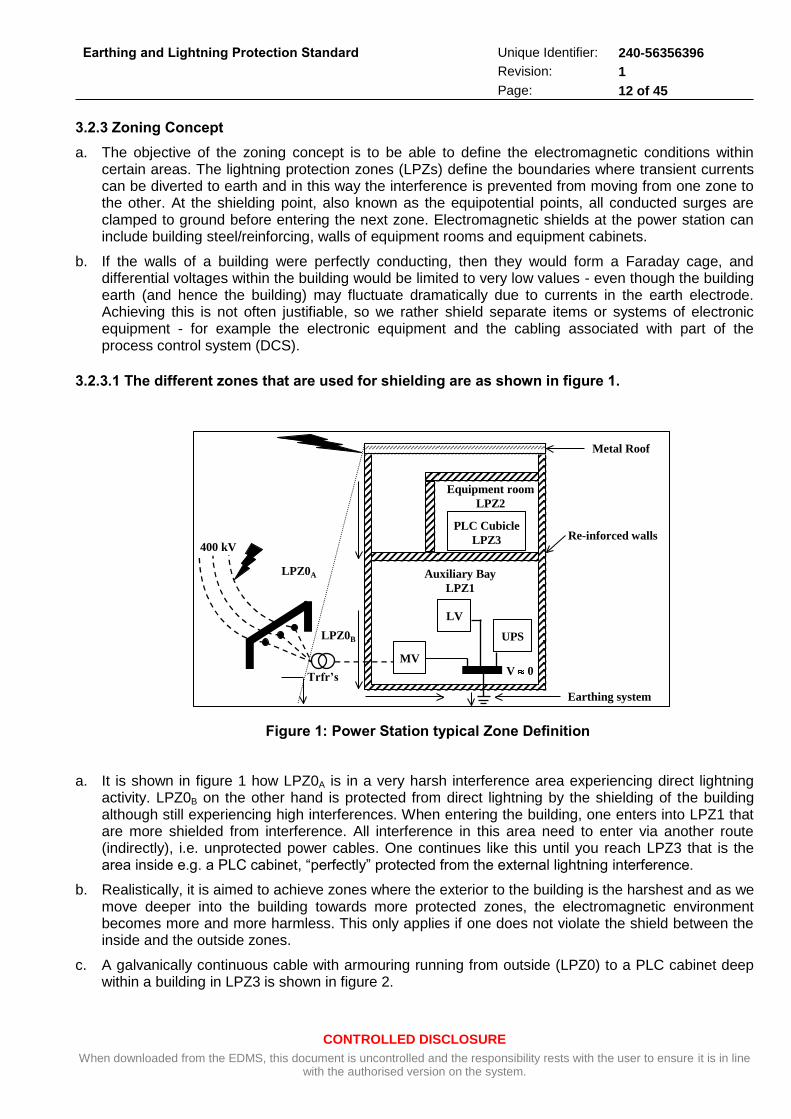
3.2.3.1 The different zones that are used for shielding are as shown in figure 1.
Figure 1: Power Station typical Zone Definition
a. It is shown in figure 1 how LPZ0A is in a very harsh interference area experiencing direct lightning activity. LPZ0B on the other hand is protected from direct lightning by the shielding of the building although still experiencing high interferences. When entering the building, one enters into LPZ1 that are more shielded from interference. All interference in this area need to enter via another route (indirectly), i.e. unprotected power cables. One continues like this until you reach LPZ3 that is the area inside e.g. a PLC cabinet, “perfectly” protected from the external lightning interference.
b. Realistically, it is aimed to achieve zones where the exterior to the building is the harshest and as we move deeper into the building towards more protected zones, the electromagnetic environment becomes more and more harmless. This only applies if one does not violate the shield between the inside and the outside zones.
c. A galvanically continuous cable with armouring running from outside (LPZ0) to a PLC cabinet deep within a building in LPZ3 is shown in figure 2.
Equipment room
LPZ2
PLC Cubicle
LPZ3
Auxiliary Bay
LPZ1
MV
LV
UPS
Re-inforced walls
Metal Roof
400 kV
Trfr’s
LPZ0A
LPZ0B
V 0
Earthing system
CONTROLLED DISCLOSURE
When downloaded from the EDMS, this document is uncontrolled and the responsibility rests with the user to ensure it is in line with the authorised version on the system.
Earthing and Lightning Protection Standard
Unique Identifier: 240-56356396
Revision: 1
Page: 13 of 45
d. At the point of entry to the next zone, surge protective devices (SPDs) would be installed as necessary to limit voltages between screen and signal lines. The interference is drained to earth at every zone boundary and with this method; one prevents it from influencing the very sensitive PLC equipment in LPZ3. The harsh external environment is shielded from the deeper zones.
e. It is important to maintain shielding integrity. The skin effect is where current flowing within conductors prefers to flow near the surface. This becomes more significant at higher frequencies. This simple fact should be remembered when installing surge protective devices (SPD’s), cable screens, or even grounding conductors. The frequency of interference is usually high.
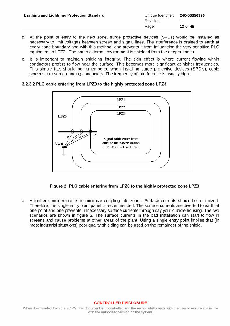
3.2.3.2 PLC cable entering from LPZ0 to the highly protected zone LPZ3
Figure 2: PLC cable entering from LPZ0 to the highly protected zone LPZ3
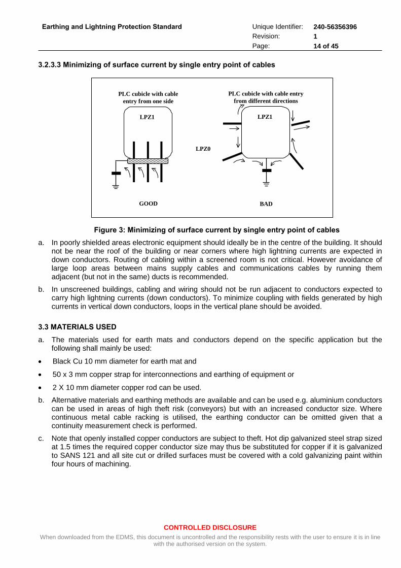
a. A further consideration is to minimize coupling into zones. Surface currents should be minimized. Therefore, the single entry point panel is recommended. The surface currents are diverted to earth at one point and one prevents unnecessary surface currents through say your cubicle housing. The two scenarios are shown in figure 3. The surface currents in the bad installation can start to flow in screens and cause problems at other areas of the plant. Using a single entry point implies that (in most industrial situations) poor quality shielding can be used on the remainder of the shield.
LPZ0
LPZ1
LPZ2
LPZ3
V 0
Signal cable enter from
outside the power station
to PLC cubicle in LPZ3
CONTROLLED DISCLOSURE
When downloaded from the EDMS, this document is uncontrolled and the responsibility rests with the user to ensure it is in line with the authorised version on the system.
Earthing and Lightning Protection Standard
Unique Identifier: 240-56356396
Revision: 1
Page: 14 of 45
3.2.3.3 Minimizing of surface current by single entry point of cables
Figure 3: Minimizing of surface current by single entry point of cables
a. In poorly shielded areas electronic equipment should ideally be in the centre of the building. It should not be near the roof of the building or near corners where high lightning currents are expected in down conductors. Routing of cabling within a screened room is not critical. However avoidance of large loop areas between mains supply cables and communications cables by running them adjacent (but not in the same) ducts is recommended.
b. In unscreened buildings, cabling and wiring should not be run adjacent to conductors expected to carry high lightning currents (down conductors). To minimize coupling with fields generated by high currents in vertical down conductors, loops in the vertical plane should be avoided.
3.3 MATERIALS USED
a. The materials used for earth mats and conductors depend on the specific application but the following shall mainly be used:
Black Cu 10 mm diameter for earth mat and
50 x 3 mm copper strap for interconnections and earthing of equipment or
2 X 10 mm diameter copper rod can be used.
b. Alternative materials and earthing methods are available and can be used e.g. aluminium conductors can be used in areas of high theft risk (conveyors) but with an increased conductor size. Where continuous metal cable racking is utilised, the earthing conductor can be omitted given that a continuity measurement check is performed.
c. Note that openly installed copper conductors are subject to theft. Hot dip galvanized steel strap sized at 1.5 times the required copper conductor size may thus be substituted for copper if it is galvanized to SANS 121 and all site cut or drilled surfaces must be covered with a cold galvanizing paint within four hours of machining.
LPZ0
PLC cubicle with cable
entry from one side
LPZ1
GOOD
LPZ1
PLC cubicle with cable entry
from different directions
BAD
CONTROLLED DISCLOSURE
When downloaded from the EDMS, this document is uncontrolled and the responsibility rests with the user to ensure it is in line with the authorised version on the system.
Earthing and Lightning Protection Standard
Unique Identifier: 240-56356396
Revision: 1
Page: 15 of 45
d. Mild steel as an alternative to copper strap is used for installations in “ground” comprising predominantly of fly ash. Galvanized steel is not ash effective as the zinc coating will deteriorate in a relatively short time due to the pH value of the moisture resulting from either spray- or rain water. Experience shows that plain mild steel is the most compatible material. Mild steel can therefore be used where earth mats or earth connections have to be installed under these conditions. The joints between mild steel straps shall be welded. Joints between mild steel and copper straps used above ground for earthing purposes should preferably be made indoor. Where they have to be made outdoor the joints must be protected against corrosion of the joint by wrapping it with Denso-tape to about 100 mm on either side of the joint. Steel/copper joints are to be brazed with silver alloy rod or preferably using an exothermic welding process.
e. Special anti-theft earth conductor is used in high risk areas where personnel activity is generally low and remote located plant. Due to the high cost of these type of conductors it is not used for long conductor runs but only used for connections between equipment and the main earth conductors for example high mast earth straps (or any metal structure earth connections), construction ring substations, switchboard connections (between board and rack earth conductor), parallel cable rack inter-connections and areas where repetitive copper theft takes place during construction, The effective copper area specification is used for sizing of this conductor in accordance with the application sizing requirements given in Appendix A.
3.4 BRAZING OF COPPER
Brazing is a process for joining metallic materials with the aid of an additional molten material (the solder) together with a flux, if necessary, and/or with inert gases. The melting temperature of the solder is above 450°C, but less than that of the materials to be joined. Thus, the surfaces of the materials can be made wet without being melted. The advantage of brazing compared to welding is the lower working temperature and the rapid completion of the joints.
3.4.1 Filler Metals and Fluxes
a. Filler metals and fluxes are to be selected according to the application and must be matched to each other and the materials. Fluxes contain aggressive chemicals in order to produce the desired effect; fluxes clean the joint to be made and prevent access of oxygen from the air.
b. For copper-to-copper joints (brazing) use only the filler metal LAg 40Cd (Hartlot 4003, refer DIN 8513). For steel-to-copper joints use only filler metal LAg 5P (Silfos 15). For large cross-sections and because of the low working temperature use filler metal LAg 40Cd. For smaller cross-sections, or when the remaining traces of flux cannot be removed, use filler metal Lag 15P. This filler metal contains phosphorus and therefore needs no extra flux.
3.4.2 Types of Joints
Brazed copper strap joints should be of either the butt or lap type:
a. Butt joints are made by putting the flat copper bars to be joined in such a way that no overlapping takes place. The joints are reliable and easy to make but must be carefully prepared and clamped. Butt joints should be avoided if possible if high mechanical stresses are involved.
b. Lap joints on the other hand are made by having copper bar overlapping. They are generally easier to prepare for brazing than butt joints. The brazed area of a lap joint should be at least be four to five times the cross-sectional diameter of the thinnest of the two flat copper bars to be joined.
c. Lap joints are always used for round copper rod with an overlap of at least 30 mm.
CONTROLLED DISCLOSURE
When downloaded from the EDMS, this document is uncontrolled and the responsibility rests with the user to ensure it is in line with the authorised version on the system.
Earthing and Lightning Protection Standard
Unique Identifier: 240-56356396
Revision: 1
Page: 16 of 45
3.4.3 Preparations for Brazing
a. The edges of the brazing surfaces should firstly be deburred, then brush it down to the bare metal using a steel wire brush (not emery cloth) and degreased. When the brazing surfaces have been cleaned, do not touch them with bare hands.
b. Ensure a good support (e.g. firebricks) when the bars are laid flat and allow the joint to project beyond the support so that heat can also be applied from below. If possible, arrange the pieces to be brazed so that there are horizontal brazing surfaces for using sheet filler metal. When brazing with sheet filler metal (approximately 0.2 mm thick), arrange for the upper piece to be movable in the direction of the brazing surface so that as the filler metal melts the correct gap can be produced. This is achieved either by the weight of the piece of material or by applying extra force.
c. For small pieces of a light weight material use a suitable device to exert extra force on the movable piece of material so that the prescribed gap can be produced. Such devices provide satisfactory clamping of the pieces being brazed and at the same time prevent the upper piece floating when the flux and filler metal melt.
d. Do not press on the joint by hand as it is solidifying because the upper piece may be moved, which would spoil the joint. Place the sheet filler metal centrally to the flat copper bar, it must cover about two-thirds of the brazing area.
e. Vertical gaps should not be brazed with sheet filler metal but strip filler metal, allowing a 0.05 mm to 0.2 mm gap.
3.4.4 Brazing
a. When the standard filler metal Lag 40Cd (Hartlot 4003) is to be used for brazing, first apply Type "h" flux (F-SH1 as per DIN 8511) generously to both brazing surfaces and their surroundings with a brush before heating the joint. Next, heat the joint uniformly and over a large area, using a wide-flame torch if possible. If normal welding torches are used move the flame back and forth over the full brazing surface quickly and evenly. For large joints use several welding torches or wide-flame torches. Adjust them to a neutral flame of a slightly reducing flame, i.e. with excess gas.
b. If possible, do not use a flame to make steel-to-copper joints as there is a danger of hydrogen embrittlement occurring in the copper. If a flame must be used, ensure that the flame does not contact the surfaces to be brazed. Cover the work piece with graphite plates and clamp the plates using copper sections. Only heat the graphite as the heat will flow from the graphite to the work piece. The Type "h" flux becomes viscous at approximately 500°C. After further heating the working temperature of 610°C is reached within a short time.
c. When brazing with Lag 15P the working temperature of approximately 710°C has been reached when the metal is just glowing red hot in a slightly darkened room. Strip filler metal should only be applied on one side of the joint with the flame on the opposite side. If the temperature of the material is correct the filler metal will run automatically into the joint gap. Do not use the torch flame to drive the filler metal into the gap or to melt off the strip filler metal. When the joint gap is full of filler metal, stop heating and avoid shaking or disturbing the joint.
d. Brazing should be completed within approximately three minutes at the most after beginning of heating. Allow the joint to cool down to 300°C and if possible, pour warm water on to it so that the flux washes away. Remove any remaining traces of flux with a steel wire brush but do not use tools on the concave fillets of the brazing. If the brazing is not completed in time set up the joint again, clean it with a steel wire brush, apply more flux and heat up again using a larger torch. Dark brown flux indicates that the brazing has taken too long. Do not attempt to rebraze a defective joint without first separating the joint and removing all traces of filler metal from the brazing surfaces (e.g. by filling).
CONTROLLED DISCLOSURE
When downloaded from the EDMS, this document is uncontrolled and the responsibility rests with the user to ensure it is in line with the authorised version on the system.
Earthing and Lightning Protection Standard
Unique Identifier: 240-56356396
Revision: 1
Page: 17 of 45
e. If the strength of brazed joints is to be maintained they should not be exposed to temperatures above 200°C.
3.5 CONDUCTORS
a. The station earth mat shall consist of 10 mm diameter black copper rod (except in the transformer bay where two copper rods run in parallel), laid at a depth of one meter. The rods under the main buildings and the transformer bays shall be arranged to provide a matrix such that the maximum size of each mesh does not exceed 800 m2
b. All earth mats shall be connected to the main station earth mat by at least two connections of 50 X 3 mm flat copper bar. These do not run side by side and where possible connect to diagonally opposite portions of the earth mat system.
3.5.1 Fault Levels
All earthing shall be designed to allow for the following fault levels:
Table 1: Fault Levels
VOLTAGE LEVEL MAXIMUM EARTH FAULT
(MVA)
EARTH FAULT CURRENT
(A, rms)
400 kV 30 000 43 500
22 kV (generator voltage) N/A 10
11 kV 500 120
6.6 kV 250 300
690 V 57 50 000
400 V (unfused) 35 50 000
3.5.2 Design Basis
a. The sizes of earth conductors have been determined on the basis that the temperature of copper buried in ground will not exceed 4500C in 5 seconds assuming no heat is lost. This is equivalent to a permissible current density of 100 A per square millimetre.
b. For any exposed earthing copper, the temperature is limited to 2500C after 5 seconds. This is equivalent to a permissible current density of 85 A per square millimetre. Circuits fed by fuses normally require only the minimum size of conductor.
3.5.3 Conductor Sizes
a. Whenever a connection is made from an earth bar to the earth mat, it is assumed that the current divides from the connection to both sides of the earth mat. Hence, any connection to earth may be twice the cross-sectional area of the earth mat conductor or earth bar. Should a greater area be required for the earth connections, two or more connections shall bee made to different portions of the earth mat, preferably to diagonally opposite sides of the nearest mesh of the mat.
b. The minimum size of annealed copper strap shall not be less than 25 mm x 3 mm while other standard sizes are 40 mm x 3 mm, 50 mm x 3 mm and 50 mm x 6 mm. The annealed copper earth rod shall be 10 mm diameter.
CONTROLLED DISCLOSURE
When downloaded from the EDMS, this document is uncontrolled and the responsibility rests with the user to ensure it is in line with the authorised version on the system.
Earthing and Lightning Protection Standard
Unique Identifier: 240-56356396
Revision: 1
Page: 18 of 45
c. In preparation of the tables and drawings, consideration is taken of the existence of parallel paths i.e. earth wires to high-voltage yard structures, and separate oil conservator and cooling systems on transformers, cable sheaths, where applicable, etc.
d. Appendix A gives details of earthing conductors used. The required cross-sectional areas shall be obtained by using standard sizes of copper in appropriate combinations.
e. The station earth mat conductor shall be 10 mm diameter black rolled copper rod.
3.5.4 Earthing Tails
Earth tails protruding from reinforcing of concrete structures or buried portions of the earth mat shall be 500 mm long to permit termination of exposed portions of the earthing system onto the earth mat.
3.5.5 Connections
a. Interconnections of 10 mm diameter copper rods forming the earth mat are made by means of brazing or exothermic welding.
b. Flat copper bars for earth tails shall be silver soldered or welded exothermically onto the copper rod or embedded reinforcing bars as per relevant sheets of drawing 0.54/393 where applicable.
c. Where equipment is earthed, connections to earth shall be made by brazed lap joints.
3.6 INSTALLATION
This section discusses the plant specific implementation of the theory and philosophy as discussed earlier in the document.
3.6.1 Earthing with Cable Racking
a. Earthing conductors shall be installed on all the cable racks at the power station. The cable racks serve an excellent medium of ensuring continuity in the plant. It serves as a secondary earth mat (surface equipotential bonding system) connected to the station and local earth mats whenever possible. Even if copper is not installed on the rack, it links equipment. The metal is conducting and helps to lower the resistance between equipment therefore improving continuity. It is important that the cable racks are bolted together to ensure continuity.
b. Special cable racks with an imbedded earth conductor is used. This type of rack eliminates the installation of the copper conductor after rack installation and prevents theft of conductors from the racking. Note that not all racks are of the imbedded copper type i.e. where several racks are running in parallel, only one of these racks with two imbedded copper conductors is required.
c. Avoid parallel running of power cables and signal cables. The distance between power and control cables should be at least 300 mm. When control cables cross power cables, make sure this is done at an angle as near to 90 degrees as possible. The cable racks support the cables therefore it should be installed in such a way as to limit interference between cables.
3.6.2 Power and Control Cables 600/1000 V
a. Cables are dimensioned in accordance with the regulations concerning short-circuit protection, operating voltage, permissible touch voltage appearing under fault conditions and current-carrying capacity of the cable. In addition to safety regulations, the cable type also supports the EMC protection of the installed equipment.
CONTROLLED DISCLOSURE
When downloaded from the EDMS, this document is uncontrolled and the responsibility rests with the user to ensure it is in line with the authorised version on the system.
Earthing and Lightning Protection Standard
Unique Identifier: 240-56356396
Revision: 1
Page: 19 of 45
b. Where earth continuity conductors are provided as a separate core in cables this earth core shall be connected to the earth bar of the switchboard, cubicle, etc. at the origin and to the internal earthing point provided in the motor termination box, local control station etc. of the target point. For this purpose the black conductor is covered with a tightly fitting yellow-green sleeve before a lug is crimped onto it.
3.6.2.2 Supply Cabling
a. At low current (< 300 A) when only one cable is sufficient, the supply cable can be either of unshielded or shielded symmetrical multi-core type. The shield is connected to earth at both ends.
b. The supply of high current (>300 A) applications can be either a busbar or a large current cable system. The alternative large current supply is constructed by using parallel cables. A large current system typically consists of several single core cables. It is designed to reduce the conductor material, because of better cooling of separate conductors.
3.6.2.3 Motor Cables
a. To meet the EMC requirements of equipment like variable speed drives it is important to use shielded symmetrical cable types. To be effective at high frequency, the shield conductivity must be at least 1/10 of the phase conductor conductivity. This is easily met with a copper or aluminium shield but the cross-section of a steel shield has to be ample. To operate as a protective conductor the shield conductivity must be at least 50%.
b. The first alternative is a three-core cable equipped with concentric protective copper shield. In that case, the wires are at an equal distance from each other and from the shield, and the shield is used as a protective conductor.
c. The alternative with wire armour, where the stranded wire iron armour is connected to earth at both ends, needs a separate high-conductivity earth conductor. The length of unshielded part of the cable should be as short as possible.
d. When cabling a high power frequency converter and motor, several conductor elements have to be used in parallel. Always use symmetrical cabling.
e. The field cable of a DC motor is a heavy source of interference because of the abrupt commutation. Therefore, always use shielded field cable. Single core cables should not be used for DC drive applications.
f. All armoured cables shall be earthed as shown on the relevant drawings in 0.54/393.
3.6.3 Process Control (and some protection) Cables
These include standard multi-core, unarmoured and screened cables and special cables such as coaxial, compensating and other cables. In general these cables are not armoured but have braided screens or taped screens with screen drain wires to prevent the coupling in of interference voltages. The type of screening depends on the interference frequency. The braided type screens are more efficient against the higher frequencies from i.e. hand held radios (> 500 MHz). The screens shall be earthed on both sides, except for cables longer than 500m.
3.6.3.1 Signal Cables
The principle of uniform, equipotential grounding is extended to all structural levels of installations in large buildings containing electrical equipment. Examples of levels are floor, equipment cubicle and circuit board level. It is not possible to keep all the levels of a large system at the same high-frequency potential, but applying the uniform grounding at all levels will ensure the electromagnetic compatibility.
CONTROLLED DISCLOSURE
When downloaded from the EDMS, this document is uncontrolled and the responsibility rests with the user to ensure it is in line with the authorised version on the system.
Earthing and Lightning Protection Standard
Unique Identifier: 240-56356396
Revision: 1
Page: 20 of 45
3.6.3.2 Interfacing problem of systems with dissimilar grounding
a. The different installations being supplied by the various manufacturers may apply other principles of grounding, e.g. low frequency EMC. The latest ideas about earthing employ the uniform earthing system where everything is bonded to everything. These systems have to operate together. The dissimilarity may create matching problems, which have to be solved for each case. Physically large installations (dimensions, power) normally need some kind of matching. Matching is done to obtain sufficient compatibility. Sometimes it is reasonable to accept a lower immunity level. However, the legal requirement of emission and immunity must be fulfilled.
b. Usually matching elements between the systems are transformers, opto-couplers, optical fibre links, galvanic analogue isolation and common mode interference filters and inductors. All these methods can improve signal transmission. Galvanic isolation of control signals improves the interference immunity and is recommended specially at long distances. Isolation prevents interference caused by common impedance coupling (ground loop) and suppresses inductive coupling interference. Weak signals are isolated and amplified exactly at the source; normal signals can also be isolated at the receiving end. Isolation transformers are used for power supplies.
c. In particular cases with high emission levels, common mode inductors can be used in signal cables to avoid interfacing problems between different systems. Common mode disturbances could be suppressed by wiring signal conductors through the common mode inductor ferrite core. The ferrite core increases inductance of conductors and mutual inductance, so common mode disturbance signals above a certain frequency are suppressed. An ideal common mode inductor does not suppress a differential mode signal.
d. The interfacing practice will not be discussed in detail, but it is important to be aware of the problem areas of interfacing before implementation.
3.6.4 Control Cable Shielding
It is very important to use the correct cable types to meet the EMC compatibility as incorrect cable types can cause severe interference problems. A shielded control cable will reduce disturbances and should therefore always be used especially with the increased use of portable communication equipment.
3.6.4.1 Analogue and Low Voltage Digital I/O Signals
a. Twisting the signal wire with its return wire reduces disturbances caused by inductive coupling. Pairs should be twisted as close to terminals as possible. A double-shielded twisted pair cable must be used for analogue signals, use one individually shielded pair for each signal and be careful when using a common return for different analogue signals.
b. A double-shielded cable is the best alternative for low voltage digital signals but a single shielded twisted multi pair cable can also be used. Never use 24 V DC and 230 V AC signals in the same cable.
3.6.4.2 Serial Communication
There are several alternatives depending on the type of communication. Use double shielded or coaxial cables in internal communication in sensitive equipment like variable speed drives. The serial communication can also be implemented with optical cables. A communication system may also have its own cable specification.
CONTROLLED DISCLOSURE
When downloaded from the EDMS, this document is uncontrolled and the responsibility rests with the user to ensure it is in line with the authorised version on the system.
Earthing and Lightning Protection Standard
Unique Identifier: 240-56356396
Revision: 1
Page: 21 of 45
3.6.4.3 Shield Connection
a. Normal practice is to earth the screen at the source of the cable to earthing terminals and to insulate the drain wire together with the screen at the remote cable end to avoid the creation of earth loops. The unshielded part of the cable shall be minimized. The ground connection of the shield shall be kept as short as possible.
b. One end grounded shields does not suppress electromagnetic field or inductive disturbance. Grounding the shield of the signal cable at both ends will improve suppression above a certain frequency, but grounding at both ends forms a closed ground loop, and if the ends of the cable screen are at different potentials, as in a short circuit situation of high power equipment, a low frequency current will flow through the screen. Therefore, if HF grounding is needed, the other end of the shield can be grounded via a capacitor.
c. Where the signal is of such magnitude that radio frequency (RF) interference is possible, double-shielded type cables with braided screens shall be used. The outer screen is normally earthed at a suitable earth point at both ends of the cable and the inner shield is connected to the circuit earth point.
3.7 CABLE JUNCTION BOXES
Cable junction boxes are not earthed provided that at least two earth paths exist through cable sheaths and armouring. Failing this, metal junction boxes shall be earthed as shown on the relevant sheets of drawing 0.54/393. Moulded plastic junction boxes of thermoplastic material do not have to be earthed but have to be fitted with an internal earth or connecting point to provide for earth continuity of either cable armouring or separate earth core.
3.7.1 Computer and Computer Room Earthing
Details of the earth grid in a computer room as well as its bonding to the main station earth mat shall be carried out according to the requirements of the supplier of the computer and ancillary equipment.
The un-insulated earthing circuit looping within the computer room shall be connected directly via the shortest route with only one connection to the main station earth mat, to prevent loops. Usually the un-insulated earthing circuits for the bonding of the computer flooring, frames and cabinet earths are separated from the insulated electronic earths. The electronic earths are brought to a common insulated bar or junction box and shall be bonded to the earth mat only from there also via an insulated earth (cable).
3.7.2 Earth Mats under foundations and floors
Where the earth mat passes under concrete foundations or floors, the lowest earthing resistance as well as the minimal corrosion effect between copper and reinforcing bars is achieved if the 10 mm diameter copper rod is placed directly on top of the blinding, then cast in concrete by the foundation or floor.
3.7.3 Structural Steelwork
a. The steelwork structures in the transformer bays shall be connected to the earth mat in accordance with the relevant sheets of drawing 0.54/393.
b. The boiler and turbine house main building columns shall be connected to the earth mat as shown on the relevant drawings. The main structural steelwork of all ancillary buildings shall be connected to their relevant earth mats.
c. Steel columns supporting equipment such as the bag filter houses, inclined conveyors, etc. are connected to the station earth mat with at least one 50 X 3 mm earth strap or a 2X10 mm diameter copper rod.
CONTROLLED DISCLOSURE
When downloaded from the EDMS, this document is uncontrolled and the responsibility rests with the user to ensure it is in line with the authorised version on the system.
Earthing and Lightning Protection Standard
Unique Identifier: 240-56356396
Revision: 1
Page: 22 of 45
3.7.4 Reinforcing Steel in Concrete Columns
a. Reinforcing steel in concrete shall be earthed as indicated on the relevant sheet of drawing 0.54/393. Note that this is a very good earthing method, providing very low continuity resistance values.
b. A continuous reinforced concrete structure provides very good protection of its occupants and contents against lightning, owing to the continuous steel reinforcement forming a metal cage. The steel that is bonded together in numerous places, and that makes low resistance contacts in splice joints, provides an adequate number of parallel paths that enable the lightning discharge current to flow safely to the general mass of the earth without ill effects to the occupants, contents or the strength and durability of the structure.
c. Note that building regulations generally exclude the use of reinforcing steel for the conduction of current. Such exclusion is specifically aimed at the use of reinforcement for the conduction of power frequency currents, either during normal operation of the electrical system or under fault conditions, but does not relate to the effects of natural phenomena such as lightning.
d. For internal down conductors, use the reinforcing steel of the vertical columns, particularly those on outer corners, provided that the reinforcement is electrically continuous. Alternatively, use conductors cast in concrete, metal vertical columns, storm water drain pipes, external metal staircases, fire escapes or other metal structures.
3.7.5 Metal Roofs and Cladding
a. Metal roofs or steel trusses not in direct contact with building steelwork shall be connected to the earth mat at diagonally opposite points of the building.
b. Structures having metal roofs do not require air terminals, but must be earthed by down conductors. Metal sheets separated from each other by insulating strips or by epoxy or plastic coatings, may be regarded as providing a continuous metal roof.
c. Un-insulated cladding not in direct contact with building steelwork is bonded to the building steelwork as shown on the relevant sheet of drawing 0.54/393. Where cladding is fully insulated (e.g. sheets covered with a bitumastic compound, and fully insulated from one another) the sheets do not require earthing.
3.7.6 Fire Protection
a. The piping of the fire protection shall be earthed in the region of the transformers to reduce the touch potential. The piping shall also be earthed at various points. Care must be taken in the installation of fire protection and detection equipment because the equipment is applied in harsh environments in terms of interference i.e. Generator Transformer yard, HV Yard, Generator etc. Suitable earthing and EMC filtering should be added to prevent false operations.
b. Herewith some general requirements with respect to the fire protection system:
Earth the unistrut or cable trunking containing the control cables to the deluge valves.
Earth the deluge valves (use copper braid).
Earth the conduit containing the signal wires between the sensors (if installed) and the control cabinet.
Bond the conduit to the cable trays and cable trunking.
Use screened, twisted pair cables for the signal cables.
CONTROLLED DISCLOSURE
When downloaded from the EDMS, this document is uncontrolled and the responsibility rests with the user to ensure it is in line with the authorised version on the system.
Earthing and Lightning Protection Standard
Unique Identifier: 240-56356396
Revision: 1
Page: 23 of 45
3.7.7 Ancillary Buildings
a. These buildings include e.g. the electrical substations, water treatment plant, auxiliary cooling system, workshop and stores, station services building, hydrogen plant, coal silos, fuel oil plant, administration buildings, etc.
b. Each building shall be provided with its own earth mat. The building earthing system shall be connected to the main station earth to ensure continuity. All major apparatus in the building shall be connected to a main earth strap that runs in a cable-tunnel or -trench and shall be connected to the earth mat.
c. The individual building or area earth mats on the terrace shall be bonded to the main station earth mat by at least two connections of 10 mm diameter copper rod each, linking into separate meshes of the main station earth mat where possible. Individual earth mats for buildings or areas off terrace must be large enough to provide a resistance to earth of not more than 0.2 ohm. This is achieved by either putting 10 mm diameter earth rod into cable trenches dug for cables laid directly in ground or by driving earth rods to SANS 1063 into the ground.
3.7.8 Process Control and Electronic Equipment
Earthing of the process control and electronic equipment is not dealt with in this document. The manufacturer shall provide a detailed philosophy and design with installation and testing instructions. This document shall be issued to the earthing installation contractor during the design phase for installation.
3.7.8.1 Grounding of Junction Boxes
Wall mounted junction boxes shall be connected to the earth mat by the shortest possible low induction path. The cable racking earth conductor provides the equipotential earth bonding system and is used for this junction box connection.
3.7.8.2 Cable Support Structures and Cabling
The process control cables are also laid on the station cable racking system. This system is connected to the power station equipotential surface earth bonding system. Care should be taken to ensure segregation of the control and instrumentation cables from the low voltage and medium voltage cables. The minimum required clearance is 300 mm.
3.7.8.3 Earthing and handling of Screens
In connection cables between cabinets the screen shall be connected on both ends, for longer connections the screen shall be connected on one end only. For cables running from the cabinets to other plant components, the screen shall be earthed in the cabinet only. Note that there are special requirements for the connection of the screens of the different types of cables.
3.8 ELECTRICAL PLANT PROTECTION EQUIPMENT
a. It is essential that the electrical plant protection equipment is immune to interference, firstly because it is the function that must clear the fault and prevent plant and personnel damage and should therefore operate correctly. It is secondly connected to trip circuits and functions that if they operate incorrectly, will trip the plant. The pyrometer flame protection of the boiler is an example of where the equipment can cause unit trips and it is critical to design these systems for EMC.
b. The reliability of the protection equipment shall be ensured by implementing special measures:
CONTROLLED DISCLOSURE
When downloaded from the EDMS, this document is uncontrolled and the responsibility rests with the user to ensure it is in line with the authorised version on the system.
Earthing and Lightning Protection Standard
Unique Identifier: 240-56356396
Revision: 1
Page: 24 of 45
c. The protection equipment is supplied from a 220 V DC system that is used only for electronic equipment power supplies. This is to ensure that the equipment is not subject to interference from e.g. motor starting that cause mal-operation of the protection. The DC system is also called the “clean” supply because of this reason.
d. All the protection relays are also tested for sensitivity to interference and earth faults. This is known as the capacitor discharge test and the earth fault test. Note that these are severe tests and ensure that the protection does not operate for supply interference from e.g. switching, electrical short circuits, supply problems etc.
e. The protection equipment is always installed in separate cubicles that act as an interference shield in the electrical switchgear environment.
3.9 NEUTRAL AND RESISTANCE EARTHING
a. The transformer neutrals (except 400 V and 690 V neutrals) are earthed either directly or via earthing transformers and resistors as discussed in this paragraph. Eskom deviates from the SANS 10198 code of practice on all 400 V neutrals. The transformer is not earthed directly at the transformer but only via a removable link in the incomer panel of the low voltage switchboard. The neutral is earthed in only one place at the switchboard.
3.9.1 The Main Electrical Systems are earthed as per the following table:
Table 2: Neutral and Resistance Earthing
ELECTRICAL SYSTEM TYPE OF EARTHING
22/420 kV Generator Transformer: Solid earth on star connected 400 kV side
22/11.5 kV Unit Transformer Earthing transformer and resistor on star connected 22 kV side and earthing resistor on the 11.5 kV star connected sides of the transformer
11/6.9 kV Service Transformer Neutral earthing resistor on 6.9 kV side of transformer
132/11 kV Station Transformer NEC/NER
Other 11/6.9 kV transformers Solid earth
11 kV/420 V Dry type transformers Solid earth (once in switchboard)
11 kV/690 V Dry type transformers Solid earth (once in switchboard)
11 kV/420 V Oil type transformers Solid earth (once in switchboard)
6.6 kV/420 V Dry type transformers Solid earth (once in switchboard)
6.6 kV/420 V Oil type transformers Solid earth (once in switchboard)
a. The details and integration of each of the different resistance earthing systems are discussed in the following paragraphs.
3.9.2 Generator Earthing
a. It is common practice to ground generators via some sort of external impedance to facilitate protection of the stator winding. This protection limits the magnitude of the earth fault current and subsequent core damage by the arc that burns the core and welds the laminations together (that leads to overheating due to excessive eddy currents). Using this high impedance protection method also provides a means for detecting ground faults within the generator.
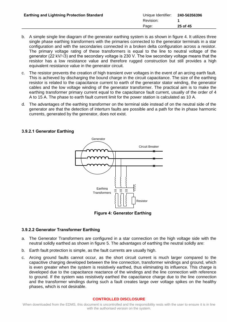
CONTROLLED DISCLOSURE
When downloaded from the EDMS, this document is uncontrolled and the responsibility rests with the user to ensure it is in line with the authorised version on the system.
Earthing and Lightning Protection Standard
Unique Identifier: 240-56356396
Revision: 1
Page: 25 of 45
b. A simple single line diagram of the generator earthing system is as shown in figure 4. It utilizes three single phase earthing transformers with the primaries connected to the generator terminals in a star configuration and with the secondaries connected in a broken delta configuration across a resistor. The primary voltage rating of these transformers is equal to the line to neutral voltage of the generator (22 kV/√3) and the secondary voltage is 230 V. The low secondary voltage means that the resistor has a low resistance value and therefore rugged construction but still provides a high equivalent resistance value in the generator circuit.
c. The resistor prevents the creation of high transient over voltages in the event of an arcing earth fault. This is achieved by discharging the bound charge in the circuit capacitance. The size of the earthing resistor is related to the capacitance current to earth of the generator stator winding, the generator cables and the low voltage winding of the generator transformer. The practical aim is to make the earthing transformer primary current equal to the capacitance fault current, usually of the order of 4 A to 15 A. The phase to earth fault current limit for the power station is calculated as 10 A.
d. The advantages of the earthing transformer on the terminal side instead of on the neutral side of the generator are that the detection of interturn faults are possible and a path for the in phase harmonic currents, generated by the generator, does not exist.
3.9.2.1 Generator Earthing
Generator
Circuit Breaker
Earthing
Transformers
Resistor
Figure 4: Generator Earthing
3.9.2.2 Generator Transformer Earthing
a. The Generator Transformers are configured in a star connection on the high voltage side with the neutral solidly earthed as shown in figure 5. The advantages of earthing the neutral solidly are:
b. Earth fault protection is simple, as the fault currents are usually high.
c. Arcing ground faults cannot occur, as the short circuit current is much larger compared to the capacitive charging developed between the line connection, transformer windings and ground, which is even greater when the system is resistively earthed, thus eliminating its influence. This charge is developed due to the capacitance reactance of the windings and the line connection with reference to ground. If the system was resistively earthed the capacitance charge due to the line connection and the transformer windings during such a fault creates large over voltage spikes on the healthy phases, which is not desirable.
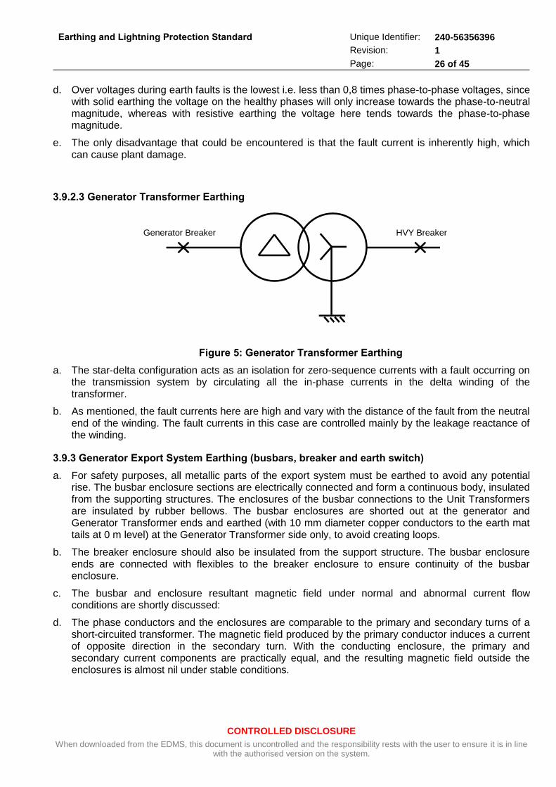
CONTROLLED DISCLOSURE
When downloaded from the EDMS, this document is uncontrolled and the responsibility rests with the user to ensure it is in line with the authorised version on the system.
Earthing and Lightning Protection Standard
Unique Identifier: 240-56356396
Revision: 1
Page: 26 of 45
d. Over voltages during earth faults is the lowest i.e. less than 0,8 times phase-to-phase voltages, since with solid earthing the voltage on the healthy phases will only increase towards the phase-to-neutral magnitude, whereas with resistive earthing the voltage here tends towards the phase-to-phase magnitude.
e. The only disadvantage that could be encountered is that the fault current is inherently high, which can cause plant damage.
3.9.2.3 Generator Transformer Earthing
Generator Breaker HVY Breaker
Figure 5: Generator Transformer Earthing
a. The star-delta configuration acts as an isolation for zero-sequence currents with a fault occurring on the transmission system by circulating all the in-phase currents in the delta winding of the transformer.
b. As mentioned, the fault currents here are high and vary with the distance of the fault from the neutral end of the winding. The fault currents in this case are controlled mainly by the leakage reactance of the winding.
3.9.3 Generator Export System Earthing (busbars, breaker and earth switch)
a. For safety purposes, all metallic parts of the export system must be earthed to avoid any potential rise. The busbar enclosure sections are electrically connected and form a continuous body, insulated from the supporting structures. The enclosures of the busbar connections to the Unit Transformers are insulated by rubber bellows. The busbar enclosures are shorted out at the generator and Generator Transformer ends and earthed (with 10 mm diameter copper conductors to the earth mat tails at 0 m level) at the Generator Transformer side only, to avoid creating loops.
b. The breaker enclosure should also be insulated from the support structure. The busbar enclosure ends are connected with flexibles to the breaker enclosure to ensure continuity of the busbar enclosure.
c. The busbar and enclosure resultant magnetic field under normal and abnormal current flow conditions are shortly discussed:
d. The phase conductors and the enclosures are comparable to the primary and secondary turns of a short-circuited transformer. The magnetic field produced by the primary conductor induces a current of opposite direction in the secondary turn. With the conducting enclosure, the primary and secondary current components are practically equal, and the resulting magnetic field outside the enclosures is almost nil under stable conditions.
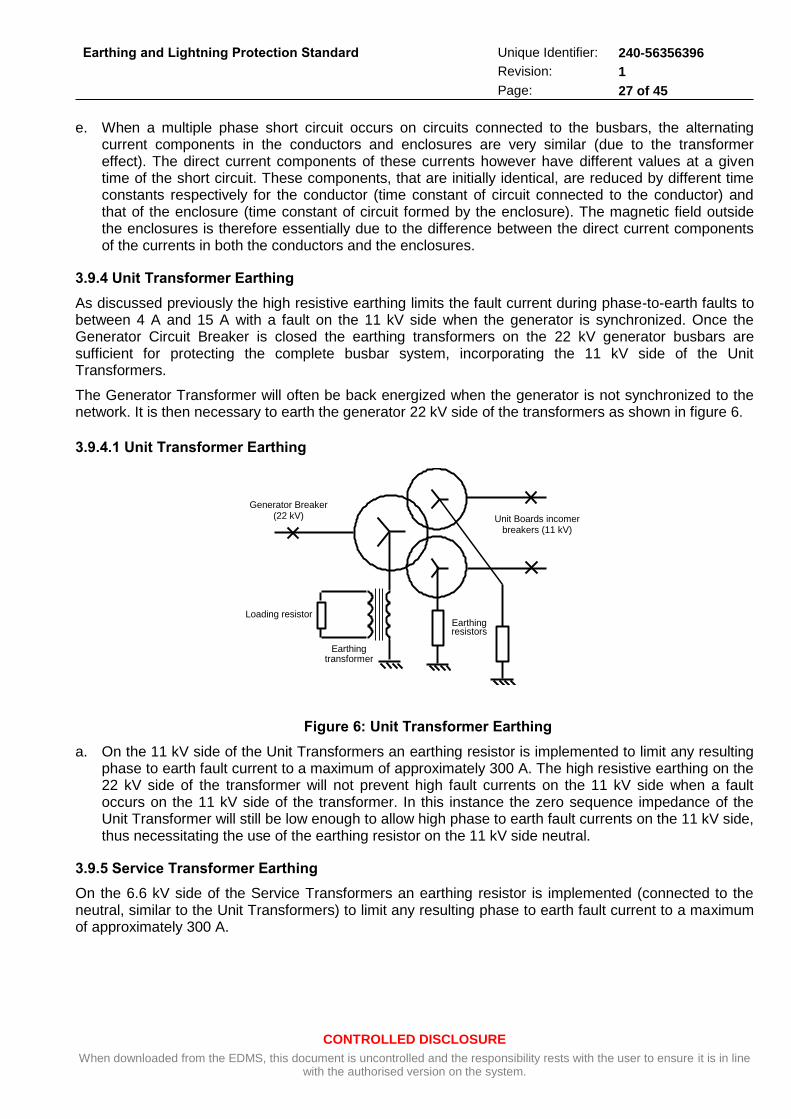
CONTROLLED DISCLOSURE
When downloaded from the EDMS, this document is uncontrolled and the responsibility rests with the user to ensure it is in line with the authorised version on the system.
Earthing and Lightning Protection Standard
Unique Identifier: 240-56356396
Revision: 1
Page: 27 of 45
e. When a multiple phase short circuit occurs on circuits connected to the busbars, the alternating current components in the conductors and enclosures are very similar (due to the transformer effect). The direct current components of these currents however have different values at a given time of the short circuit. These components, that are initially identical, are reduced by different time constants respectively for the conductor (time constant of circuit connected to the conductor) and that of the enclosure (time constant of circuit formed by the enclosure). The magnetic field outside the enclosures is therefore essentially due to the difference between the direct current components of the currents in both the conductors and the enclosures.
3.9.4 Unit Transformer Earthing
As discussed previously the high resistive earthing limits the fault current during phase-to-earth faults to between 4 A and 15 A with a fault on the 11 kV side when the generator is synchronized. Once the Generator Circuit Breaker is closed the earthing transformers on the 22 kV generator busbars are sufficient for protecting the complete busbar system, incorporating the 11 kV side of the Unit Transformers.
The Generator Transformer will often be back energized when the generator is not synchronized to the network. It is then necessary to earth the generator 22 kV side of the transformers as shown in figure 6.
3.9.4.1 Unit Transformer Earthing
Unit Boards incomer breakers (11 kV)
Generator Breaker (22 kV)
Loading resistor
Earthing transformer
Earthing resistors
Figure 6: Unit Transformer Earthing
a. On the 11 kV side of the Unit Transformers an earthing resistor is implemented to limit any resulting phase to earth fault current to a maximum of approximately 300 A. The high resistive earthing on the 22 kV side of the transformer will not prevent high fault currents on the 11 kV side when a fault occurs on the 11 kV side of the transformer. In this instance the zero sequence impedance of the Unit Transformer will still be low enough to allow high phase to earth fault currents on the 11 kV side, thus necessitating the use of the earthing resistor on the 11 kV side neutral.
3.9.5 Service Transformer Earthing
On the 6.6 kV side of the Service Transformers an earthing resistor is implemented (connected to the neutral, similar to the Unit Transformers) to limit any resulting phase to earth fault current to a maximum of approximately 300 A.
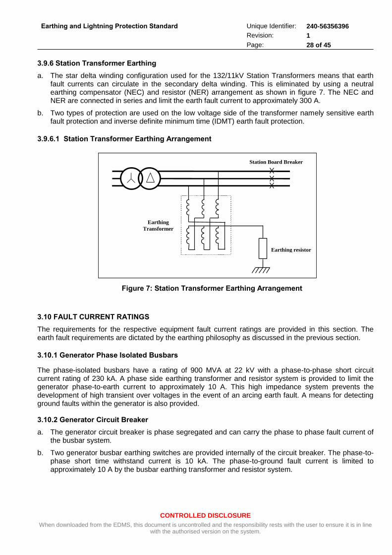
CONTROLLED DISCLOSURE
When downloaded from the EDMS, this document is uncontrolled and the responsibility rests with the user to ensure it is in line with the authorised version on the system.
Earthing and Lightning Protection Standard
Unique Identifier: 240-56356396
Revision: 1
Page: 28 of 45
3.9.6 Station Transformer Earthing
a. The star delta winding configuration used for the 132/11kV Station Transformers means that earth fault currents can circulate in the secondary delta winding. This is eliminated by using a neutral earthing compensator (NEC) and resistor (NER) arrangement as shown in figure 7. The NEC and NER are connected in series and limit the earth fault current to approximately 300 A.
b. Two types of protection are used on the low voltage side of the transformer namely sensitive earth fault protection and inverse definite minimum time (IDMT) earth fault protection.
3.9.6.1 Station Transformer Earthing Arrangement
Figure 7: Station Transformer Earthing Arrangement
3.10 FAULT CURRENT RATINGS
The requirements for the respective equipment fault current ratings are provided in this section. The earth fault requirements are dictated by the earthing philosophy as discussed in the previous section.
3.10.1 Generator Phase Isolated Busbars
The phase-isolated busbars have a rating of 900 MVA at 22 kV with a phase-to-phase short circuit current rating of 230 kA. A phase side earthing transformer and resistor system is provided to limit the generator phase-to-earth current to approximately 10 A. This high impedance system prevents the development of high transient over voltages in the event of an arcing earth fault. A means for detecting ground faults within the generator is also provided.
3.10.2 Generator Circuit Breaker
a. The generator circuit breaker is phase segregated and can carry the phase to phase fault current of the busbar system.
b. Two generator busbar earthing switches are provided internally of the circuit breaker. The phase-to-phase short time withstand current is 10 kA. The phase-to-ground fault current is limited to approximately 10 A by the busbar earthing transformer and resistor system.
Station Board Breaker
Earthing
Transformer
Earthing resistor
CONTROLLED DISCLOSURE
When downloaded from the EDMS, this document is uncontrolled and the responsibility rests with the user to ensure it is in line with the authorised version on the system.
Earthing and Lightning Protection Standard
Unique Identifier: 240-56356396
Revision: 1
Page: 29 of 45
3.10.3 Generator Transformer
The Generator Transformer neutral is solidly earthed. The high fault current is a disadvantage but this earthing method has several advantages namely:
earth fault protection is easy because the fault currents are high,
arcing ground faults cannot occur because the short circuit current is much larger compared to the capacitive charging current developed between the line connection, transformer windings and ground and
the maximum overvoltage during a fault condition is the phase-to-neutral voltage that is lower than the maximum for resistive earthing which is the phase-to-phase voltage.
3.10.4 Unit Transformers
On the 11 kV side of the Unit Transformers an earthing resistor is implemented to limit any resulting phase to earth fault current to a maximum of approximately 300 A. The high resistive earthing on the 22 kV side of the transformer will not prevent high fault currents on the 11 kV side when a fault occurs on the 11 kV side of the transformer. In this instance the zero sequence impedance of the Unit Transformer will still be low enough to allow high phase to earth fault currents on the 11 kV side, thus necessitating the use of the earthing resistor on the 11 kV side neutral.
3.10.5 Service Transformers
An earthing resistor is used on the 6.6 kV side of the Service Transformers to limit any resulting phase-to-earth fault current to a maximum of approximately 300 A.
3.10.6 Station Transformer
The neutral earthing compensator (NEC) and resistor (NER) are connected in series and limits the earth fault current to approximately 300 A.
3.11 GENERATOR AND UNIT TRANSFORMERS
a. All equipment support steelwork shall be earthed with at least two connections. Where no detailed instructions are given in reference drawings the two connections made from such steelwork preferably link to two diagonally opposite sides of the nearest mesh of the earth mat. Where the equipment is provided with an insulated earthing terminal as in the case of lightning arresters, one of the support structure earthing straps shall run up the structure and be bolted to the equipment earth terminal.
b. All overhead earth wires are terminated by means of reverse pistol strain clamps onto U-bolts provided on the supporting structures. Earthing is effected by contact of the U-bolt and strain clamp and no additional earth connections are required.
3.11.1 Generator Export System (busbars, earth switch and circuit breaker)
a. The generator shall be earthed from two points to the main station earth mat via tails on the 0 m turbine house level. Note that the generator neutral star point connection is floating.
b. The phase insulated busbars shall be earthed on one end only to the main station earth mat. This earth connection is at the busbar enclosure shorting plate, at the generator side, also connecting the three bus-ducts to each other. To prevent circulating currents, any equipment connected to the busbars e.g. cubicles, excitation transformer etc.) shall be isolated with non-conducting bellows and separately earthed to the main station earth mat.
CONTROLLED DISCLOSURE
When downloaded from the EDMS, this document is uncontrolled and the responsibility rests with the user to ensure it is in line with the authorised version on the system.
Earthing and Lightning Protection Standard
Unique Identifier: 240-56356396
Revision: 1
Page: 30 of 45
c. Secondary VT and CT connections from the breaker to the junction boxes shall be run as unarmoured cables without an earth continuity conductor. It is important that armoured cables are avoided because that can be the origin of large circulating currents in the armouring. VT and CT secondaries are earthed as per respective drawings to the earth studs in the junction boxes and from there to the nearest earth mat tail.
3.11.2 Transformers
Each transformer tank shall be earthed in accordance with the relevant drawings referring both to the earth mat layout drawing for the point of installation of the transformer as well as the manufacturers drawing indicating the position of earth terminals on the transformer tank in accordance with GGS 1074 (Specification for large power transformers in power stations, clause 4.18.12).
3.11.3 MV and LV Switchboards, Control Panels and Cubicles
a. When equipment is assembled into cabinets, panels or any enclosure it is grounded to prevent dangerous voltages under any circumstances. When assembled into the cabinets by means of mounting brackets or plates and fixing screws it must be kept in mind that connection to ground through fixing screws and the cabinet chassis is not good enough.
b. Low impedance high frequency grounding is necessary to create uniform potential to all electronics installed inside the enclosure. Therefore, bonding shall be done with separate copper strip(s) or bar(s) to the enclosure chassis.
c. Switchboards, control panels and cubicles have an earth bar running over the length of the board. This earth bar shall be connected by the earthing contractor to the earth mat once for single panels and at least on each end for larger boards. Switchboards exceeding 15 m in length shall be bonded to the earth mat in at least three positions.
d. The neutral of the main 400 V low voltage switchboard with direct transformer feeds shall be earthed inside the board at only one point. The star point neutral is earthed onto the board earth bar via a removable link. In secondary LV switchboards that are fed from a main 400V board, the neutral shall not be earthed again to avoid circulating currents.
3.12 ELECTRIC MOTORS AND LOCAL CONTROL STATIONS
a. Electric motors and local control stations and starters shall be earthed by the earthing contractor in accordance with the relevant sheets of drawing 0.54/393.
b. According to SANS 10142-1 only one earth connection is required for a motor. For smaller motors this may be provided by the fourth cable core (up to 4 X 16 mm2).For larger motors a 10 mm diameter round conductor bonding to the nearest earth bar i.e. earth conductor on cable rack or earth mat tail shall be used.
3.12.2 Boiler Feed Water Pumps
The boiler feed pump system and the associated control and protection equipment shall be earthed in accordance with the manufacturer’s recommendations that shall be provided to the earthing contractor.
3.12.3 Air Cooled Condensers
Earth connections are required between the Air Cooled Condenser steelwork and the earth mat in accordance with the ACC earthing drawing.
CONTROLLED DISCLOSURE
When downloaded from the EDMS, this document is uncontrolled and the responsibility rests with the user to ensure it is in line with the authorised version on the system.
Earthing and Lightning Protection Standard
Unique Identifier: 240-56356396
Revision: 1
Page: 31 of 45
3.13 AUXILIARY BAY CABLE TUNNELS
a. A main earth conductor comprising of a 2 X 10 mm diameter copper rod shall be installed on all the cable racks in the auxiliary bay for the whole length of the station. These shall be connected to the main station earth mat at every second row of columns via an earthling tail.
b. Equipment on basement floor level shall be connected directly to the turbine and boiler house earth mats via the earth tails (where available in close vicinity).
c. Two copper rods shall also run along the cable racks from the main cable tunnels in the auxiliary bay to the gas cleaning plant, transformer bays, air cooled condenser substations etc.
d. Bonding of the cable tray earthling to the main station earth mat shall be performed at the points where earth tails are provided from the meshes of the earth mat.
3.14 HIGH MASTS FOR AREA LIGHTING
Earth connections of 10 mm diameter copper rod from these masts shall be run along the concrete trenches or other trenches for the supply cables to the nearest intersection with the station earth mat, where they shall be bonded to the mat by brazing or exothermic welding.
3.14.1 Mini-Substations for perimeter fence lighting and fence earthing
Mini-substations located at various points on the terrace shall be earthed in accordance with relevant sheets of drawing 0.54/393. Where necessary, and depending on the distance from the main station earth mat, tie-back to this mat shall be done by means of 10 mm diameter copper rod running in cable trenches to the nearest portion of the main station mat.
Earthing of the inner perimeter fence shall be done in accordance with the relevant sheets of drawing 0.54/393. The earthing rod is buried 600 mm outside the perimeter fence and forms part of the station earth mat.
3.14.2 Construction Ring
The earthling systems of the construction power supply shall be connected with the station earth mat. In the remote locations the mini-substations shall be earthed with earth rods in accordance with the specification 0.54/393.
3.14.3 Station and Unit Diesel Generators
a. The base frames of stand-by diesel generators shall be earthed by the earthing contractor with two earth conductors each comprising 2 X 10 mm diameter copper rods, allowing for possible vibration stresses, to diagonally opposite sides of the nearest earth mat mesh.
b. It is ensured that equipment mounted on the frame is properly bonded to it.
3.14.4 Chimneys
a. Chimneys shall be provided with an earthing and lightning protection system by the chimney civil contractor.
b. The system shall comprise of an air terminal, down conductors and an earth mat in accordance with the chimney earthing drawing. Air terminal components shall be bonded to the chimney down conductors at intervals of maximum 15 m.
c. Chimney down conductors shall be spaced at intervals of maximum 15 m and is securely bonded to the reinforcement steel at intervals of maximum 15 m. Down conductors shall be cast into the concrete. The combined rated area of chimney down conductors shall not be less than 700 mm
2.
CONTROLLED DISCLOSURE
When downloaded from the EDMS, this document is uncontrolled and the responsibility rests with the user to ensure it is in line with the authorised version on the system.
Earthing and Lightning Protection Standard
Unique Identifier: 240-56356396
Revision: 1
Page: 32 of 45
d. The earth mat electrode of 10 mm diameter copper rod surrounds the chimney with inspection pits located at intervals as indicated on the relevant drawings. The aircraft warning lights shall be connected to the earthing system.
3.14.5 Flue-Ducts and Support Structures
a. The flue gas ducts shall be provided with an earthing system as per this paragraph by the earthing contractor.
b. Earth rods shall be buried along both sides of the support structures for the flue-ducts. These rods shall be connected to the earth mat surrounding the chimneys and to the earth mat of the gas cleaning plant. All steel structures supporting the flue-ducts shall be connected to these earth rods.
c. Where Teflon or other insulating “slide bearings” are installed between supports and ductwork, these are bridged by the earthing contractor with flexible copper connections (either braided tinned copper or yellow/green insulated wire of 70 mm2).
3.14.6 All Vessels
All storage tanks shall be bonded to the earth mat by the earthing contractor.
For tanks with diameters less than 5000 mm, one connection is acceptable. For all larger tanks two connections shall be required on opposite sides to separate meshes in the earth mat.
3.14.7 Conveyors
a. Mechanical interconnections of structural steel as well as sheet steel cladding are adequate for earthing and lightning protection purposes. The combined footing resistance of all concrete bases along the conveyors will ensure a low ohmic resistance for earthing purposes.
b. Fixed conveyor structures shall be bonded to the earthing system at each end by means of two separate 2 X 10 mm diameter copper rods. The connection shall be made either to the main station earth mat or that of transfer houses at the one end, and coal stockyard or ash dump substation earth mat at the other. Connections shall be made by brazing or exothermic welding for rod-to-rod connections or by copper clamp for copper to galvanized steel structures.
c. The shiftable conveyor structures shall be bonded at head and tail sides with two flexible connections (alternatively 10 mm diameter copper rod can be used) of at least 70 mm2 to the head station and the feeding conveyor respectively.
3.14.8 Equipment Moving on Rails
This paragraph discusses the requirements with respect to the earthing and lightning protection for equipment moving on rails i.e. coal stackers/reclaimers and ash stackers.
3.15 EARTHING OF RAILS
3.15.1 Longitudinal Bonding
a. At all rail joints, electrical bonds are required in addition to the mechanical connection by fishplates. The electrical bonds shall be of braided or laminated copper with a minimum cross sectional area of 70 mm2 fixed by bolting or exothermic welding on either side of the joint. An alternative is the exothermic welding of galvanized steel wire across the joint. The cross bond may consist also of 70 mm2 stranded copper conductors with green/yellow PVC insulation with crimped-on lugs.
b. At head and tail end, the rails must be bonded to the earthing system of transfer houses, head or tail stations by two 10 mm diameter copper rods. These shall not be run side by side and where possible shall connect to different portions of the earthing system.
CONTROLLED DISCLOSURE
When downloaded from the EDMS, this document is uncontrolled and the responsibility rests with the user to ensure it is in line with the authorised version on the system.
Earthing and Lightning Protection Standard
Unique Identifier: 240-56356396
Revision: 1
Page: 33 of 45
3.15.2 Cross Bonding
Cross connections between the two rails shall be established at maximum distances of 50 m by suitable flat copper bar or PVC insulated conductors as above with at least 70 mm2 cross sectional area. Again, hot dip galvanized steel strap of not less than 50 x 4 mm may be used.
3.15.3 Connections to Earth
a. It is important to reduce the lengths of fault current paths to earth to an economical minimum in particular along conveyors/rails where process control cables (typically for sequence control and interlocking) are laid along the lengths of the steel structure. Only in this way can the induction of disturbance signals into the process control systems be minimized. On fixed installations, the rails are usually run on concrete sleepers, which have a poor transition resistance to earth. It is thus necessary to install earth spikes at distances of ± 50 m along the rails on alternative sides, i.e. distance between two earth spikes on the same side to be 100 m. These distances may have to be decreased at installations with severe lightning activity or in areas with high soil resistivity to reduce the resistance to earth.
b. Where rails are continuously welded electrical bonding shall be required at the ends only to connect to the earth mats of transfer houses etc.
c. On shiftable conveyors the rails are usually installed on steel sleepers with a much lower transition resistance to earth. It is thus adequate to install earth spikes as above only about every 100 m. Once shiftable conveyors are moved new earth spikes must be installed at the head station and other points where either distance or difference in height make it impractical to run 10 mm diameter copper rods to the established earth spikes.
d. At each earth spike position, spikes are either to be driven deep enough into the ground or multiple spikes must be installed (minimal distance = length of spike) to achieve a resistance to true earth of
less than 500 . The resistance is to be measured after each extension or shift of the system.
3.15.4 Earthing of Land Junction Boxes
a. The armouring of fixed power supply cables shall be earthed as per normal instructions for the type of cable installed, either through the incoming cable gland or via separate clamp and braided earth lead or solid earth strap. Core screens are to be earthed via braided earth leads from the heat shrink terminations to the earth stud or rail provided in the land junction box.
b. Single or multiple earth conductors and screens in the trailing cable must likewise be connected to the earth stud or rail inside the box. From the external earth stud of the box an earth lead of at least 70 mm2 shall be connected to both rails. Independent of the fact that the land junction box is a fixed or a moving installation (on shifting conveyors) an earth spike is to be installed at this point.
c. The armouring (if any) of fixed process control cables shall be earthed similar to above at the signal land junction box. Screens or screen drain wires of incoming cables are to be terminated similar to the cable cores but not earthed. They are to be earthed at the feeding end of the cable(s) only.
d. Screens or screen drain wires of outgoing flexible reeling cables must be connected to an insulated terminal block or earth bar, which in turn is connectable to the internal earthing stud of the junction box. A single 70 mm2 earth lead is to be connected to the earth spike at the power cable junction box.
3.15.5 Earthing of Shiftable (ash) Conveyor Modules
a. At least one earth conductor shall be installed along the length the conveyor with sufficient slack to allow for shifting of the conveyor modules. This conductor must be of 95 mm2 bare stranded copper. Where power and control cables are run on opposite sides of the modules, two 70 mm2 conductors are preferred. The conductor(s) shall be connected to the earth systems at either conveyor end.
CONTROLLED DISCLOSURE
When downloaded from the EDMS, this document is uncontrolled and the responsibility rests with the user to ensure it is in line with the authorised version on the system.
Earthing and Lightning Protection Standard
Unique Identifier: 240-56356396
Revision: 1
Page: 34 of 45
b. Each module shall be connected by one (or two diagonally placed) earth tails of 70 mm2 with a crimped-on cable lug for connection to the module and a line clamp to the main earth conductor. The line clamp permits repositioning of the tail on the longitudinal main earth conductor, if modules are unevenly spaced after shifting.
c. Through connections i.e. short copper lengths fitted between two adjacent modules faces only are not permissible as one break can invalidate the entire earthing chain.
3.15.6 Earthing of Stacker/Reclaimer, Tripper Cars and Stackers to Rails
a. Wherever structures are not permanently joined by welding or bolting but have swivel or other joints e.g. bogies etc. earth bonds of not less than 70 mm2 shall be fitted across such joints. At least one earth shoe located as centrally as possible relative to the entire structure shall be provided. The protection against lightning or electrical fault induced fault currents is considerably improved by installing such a shoe for each rail. The shoes must be spring loaded to maintain good contact with the rails. Fault or imbalance/leakage currents should not flow through any of the multiple wheel bearings (pitting); hence, the importance of adequately sized, placed and maintained earth shoes onto the rails.
b. Earth bonds must allow some movement (of bogies) but may not be pigtailed and should have smooth contours and no sharp bends or kinks.
3.15.7 Earthing of on-board Equipment
On each separate unit such as a stacker or link conveyor, a separate earth bus shall be installed with a copper bar of at least 50 X 3 mm, preferably 50 X 6 mm. All non-current carrying metal parts of the individual on-board installation must be connected once only to this earth bus. No loops (e.g. through earth bars of switchgear) shall be established to prevent circulating currents in an earth fault situation.
3.15.8 Cross Bonding of Ash Stackers and Link Conveyors to Tripper Cars
The stacker, conveyor and tripper car are mechanically linked. Flexible earth continuity conductors of not less than 70 mm2 shall be installed along the cable routes between the three elements forming the integrated earthing of the complete unit.
3.15.9 HV Yard
a. HV yard equipment shall be installed in accordance with the relevant drawings 0.84/1753 sheet 1 and 0.84/1754 sheet 2.
b. The yard shall be connected to the power station earth mat by 2 X 10 mm diameter copper rods at each unit. Due to the high probability of lightning in the yard, it is important that this connection be tested as part of the routine earthing continuity tests. Note that the current Transmission maintenance plan requires that this be tested yearly.
3.16 TESTING AND MAINTENANCE
a. This section prescribes how to perform maintenance on the earthing system installed at the Power Station. To be able to perform proper maintenance, a good set of as-built drawings showing the earth mat layout is required. Inspections can only be done once the drawings are in place. Two things are required to determine the condition of the earthing arrangement:
visual inspections and
testing and measurements.
CONTROLLED DISCLOSURE
When downloaded from the EDMS, this document is uncontrolled and the responsibility rests with the user to ensure it is in line with the authorised version on the system.
Earthing and Lightning Protection Standard
Unique Identifier: 240-56356396
Revision: 1
Page: 35 of 45
b. The risk of plant damage due to lightning and electrical faults are minimized by repairing the defects and addressing the issues highlighted by these actions. Earthing and lightning protection integrity is dependent on a good philosophy associated with a proper installation.
3.16.1 VISUAL INSPECTIONS
a. Visual inspections shall be carried out on all the earthed equipment and a report is produced in which the following is mentioned:
Signs of corrosion on all metal structures, particularly fences, at ground level,
evidence of loose or otherwise faulty connections,
unnecessary bending of earth rods (sharp curves 90°),
unearthed electrical equipment,
unearthed structures and
any signs that the earthing copper may have been stolen.
b. A complete inspection should be performed every eighteen months, although regular plant checks (every 6 months) are recommended. The recommended maintenance schedule as shown in Appendix D shall be used to ensure that a complete inspection is performed. It is important to document all inspections.
c. Herewith the minimum requirements when performing inspections on the earthing installation:
All earth tails must be checked for corrosion. At substations where the corrosion index stipulates, this check shall be carried out more frequently. These earth tails are either copper or galvanized steel.
In the HV yard where the layer of crusher stone at the copper tail can be removed and at minimum the top 100 mm of soil. The copper is then checked for pitting (only spot checks are required).
Where the tail is galvanized steel the soil must be excavated down to below the galvanized steel-copper joint. The galvanized steel and copper must be checked for pitting.
Where a section is found to be badly pitted this section must be replaced. To do this, first bond the new section of copper to either side of the pitted section. The pitted section can then be cut away. This section must be sent away for analysis. A soil sample must be taken and sent for analysis.
Complete the substation Earthing System Checklist.
3.16.2 EARTHING TRIANGLES
a. The earth tail reference point system shall be used to enable the repeating of the continuity tests. The reference points are the earth mat tails (and major plant e.g. generator, chimney etc.), marked in the plant with green triangles, with a number that corresponds with the number on the drawing. These triangles shall be installed by the earthing contractor.
b. The continuity measurements are then performed between the triangles and between the equipment and the triangles. This can be repeated for the routine tests.
c. This is a very simple but effective system. The green triangles can also be used for measurements from equipment during problem solving with a high level of trust.
CONTROLLED DISCLOSURE
When downloaded from the EDMS, this document is uncontrolled and the responsibility rests with the user to ensure it is in line with the authorised version on the system.
Earthing and Lightning Protection Standard
Unique Identifier: 240-56356396
Revision: 1
Page: 36 of 45
3.16.3 TEST AND MEASUREMENTS
a. Periodical measurements of continuity and resistivity to true earth must be carried out and recorded in a log sheet or book to allow the recognition of changes and for counter measures if values deteriorate. Only an effectively maintained earthing system will provide the designed/required safety of personnel and equipment against consequences of fault conditions as a result of lightning activity or electrical faults.
b. It is of importance to carry out check measurements immediately after installation and then at regular intervals, recording the results in a special log. Tests should be conducted after any major electrical fault. It is vital to ensure that the earth mat of any new installation is correctly bonded to the existing earth mat. All earth connections are important but special attention should be given to:
earth connections of generator transformer star points, surge arresters, CVTs, NECs or earthing resistors and,
bonding between the secondary circuit star points of VTs and CTs, which are normally earthed at different locations.
c. Besides comparing the new and the old test results, comparisons can also be made between the resistances between similar parts on different Units. Interpretation of these measurements of continuity and resistance to true earth give an indication of the quality and expected life of the earthing installation.
d. These tests are performed to proof that the plant is properly earthed. The record keeping of the tests are important. The measurement and inspection report numbers should be reflected on the maintenance (PM) feedback.
3.16.4 Earth Resistance Measurements
a. This test gives an indication what the resistance to earth is. It is of importance where personnel can have simultaneous contact to structures and earth for example fences, conveyors, HV Yard, transformer yards etc.
b. Earth resistance tests should be carried out at least every second year, preferable before the rain season starts, when the soil is dry and ground resistance is high (this is the worst case).
c. The resistance test is performed with respect to the most important earth mat tail reference points. The reference points are earth tails in the power station marked and numbered with green triangles (with a number inside the triangle). The reference points are indicated on the drawings as they are identified and marked on site.
d. The earth tails are fixed points with recorded earth resistance readings. The readings can be compared over years to get an indication if the resistance to earth stays stable. It is important to record environmental information regarding time of the year and what the rainfall pattern was during the time of measurements, because this will influence readings. The resistance readings should be
smaller than 0.14 to keep the touch-potential smaller or equal to 165 V.
3.16.5 Continuity Measurements
a. This test gives an indication of how good the connection between any two earthing points is. Continuity tests are carried out every eighteen months on all the major earthed equipment on the power station. This test should be performed more frequently when any busbar fault or internal substation fault occurred or when there were direct lightning hits in any particular area.
CONTROLLED DISCLOSURE
When downloaded from the EDMS, this document is uncontrolled and the responsibility rests with the user to ensure it is in line with the authorised version on the system.
Earthing and Lightning Protection Standard
Unique Identifier: 240-56356396
Revision: 1
Page: 37 of 45
b. The continuity test is of more importance, because the risk of damage is dramatically decreased when the whole system rises in voltage during a surge. This will be accomplished when there is good continuity between equipment. The continuity test is done from the reference points and these points are proofed by the resistance tests.
c. While the measured resistance depends on the distance between the two chosen structures, a
rough guide for separations of less than 100 m is that 30 m or less would indicate correct copper
bonding. However, should the reading be 100 m or more then the connection is via a stray path
through steel. If steel droppers down to a buried copper earth mat are used then about 10 m should be added to the above figures.
d. Continuity tests are carried out on selected metal structures both inside the power station and outside in the associated transfer houses and substations, etc. to ensure that there is continuity between them by the buried copper earth mat. Continuity tests use a megger or micro-ohm meter.
The continuity reading should be smaller than 12 m .
3.17 DOCUMENTATION AND RECORDS
It is very difficult to maintain the earthing and lightning protection due to its nature and widespread layout and it is therefore essential that additional measures be put in place that will ensure an effective system. The earthing documentation plays an important role to ensure that the risks associated with earthing and lightning protection be minimised. Documents should be in place and accessible to personnel, kept updated and only changed as per the applicable change/modification procedure.
3.17.1 Design Standard
A well-documented design standard can be used as a training tool for new personnel, a reference tool for the project engineer, system engineer and maintenance personnel and it can also be used as part of the technical specification for modifications and additions to the plant.
3.17.2 Drawings
As mentioned in the previous section the drawings are a maintenance check reference and should reflect the as built status of the installed plant. The drawings should be easily accessible to personnel and updates and changes are managed by the change/modification procedure.
3.17.3 Maintenance Plan and PM’s (planned maintenance activities)
The maintenance plan and check sheets as shown in appendices C, D and E should be used to generate the PM’s that is used by the maintenance personnel to perform the inspections and tests.
3.17.4 Test reports
The test reports are used as a reference to determine plant defects. Their format should be standardised to ensure that the latest test results can be compared with the old test reports. It should also be registered and properly referenced in the PM to enable retrieval at a later stage.
3.17.5 Visual Check Reports
This is one of the most difficult routine maintenance tasks to perform due to the diversity of the plant, inaccessible areas of the earthing installation etc. It is an essential requirement that the person that performs the check be familiar with the plant and the associated earthing and lightning protection installation to ensure that defects are identified. The area of responsibility should not be too widespread because that will make the task too large and therefore discourage the individual to perform the task effectively.
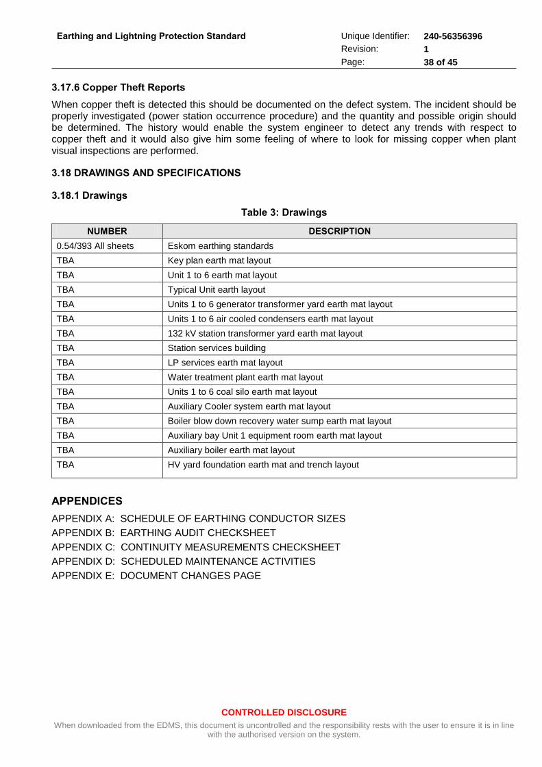
CONTROLLED DISCLOSURE
When downloaded from the EDMS, this document is uncontrolled and the responsibility rests with the user to ensure it is in line with the authorised version on the system.
Earthing and Lightning Protection Standard
Unique Identifier: 240-56356396
Revision: 1
Page: 38 of 45
3.17.6 Copper Theft Reports
When copper theft is detected this should be documented on the defect system. The incident should be properly investigated (power station occurrence procedure) and the quantity and possible origin should be determined. The history would enable the system engineer to detect any trends with respect to copper theft and it would also give him some feeling of where to look for missing copper when plant visual inspections are performed.
3.18 DRAWINGS AND SPECIFICATIONS
3.18.1 Drawings
Table 3: Drawings
NUMBER DESCRIPTION
0.54/393 All sheets Eskom earthing standards
TBA Key plan earth mat layout
TBA Unit 1 to 6 earth mat layout
TBA Typical Unit earth layout
TBA Units 1 to 6 generator transformer yard earth mat layout
TBA Units 1 to 6 air cooled condensers earth mat layout
TBA 132 kV station transformer yard earth mat layout
TBA Station services building
TBA LP services earth mat layout
TBA Water treatment plant earth mat layout
TBA Units 1 to 6 coal silo earth mat layout
TBA Auxiliary Cooler system earth mat layout
TBA Boiler blow down recovery water sump earth mat layout
TBA Auxiliary bay Unit 1 equipment room earth mat layout
TBA Auxiliary boiler earth mat layout
TBA HV yard foundation earth mat and trench layout
APPENDICES
APPENDIX A: SCHEDULE OF EARTHING CONDUCTOR SIZES
APPENDIX B: EARTHING AUDIT CHECKSHEET
APPENDIX C: CONTINUITY MEASUREMENTS CHECKSHEET
APPENDIX D: SCHEDULED MAINTENANCE ACTIVITIES
APPENDIX E: DOCUMENT CHANGES PAGE
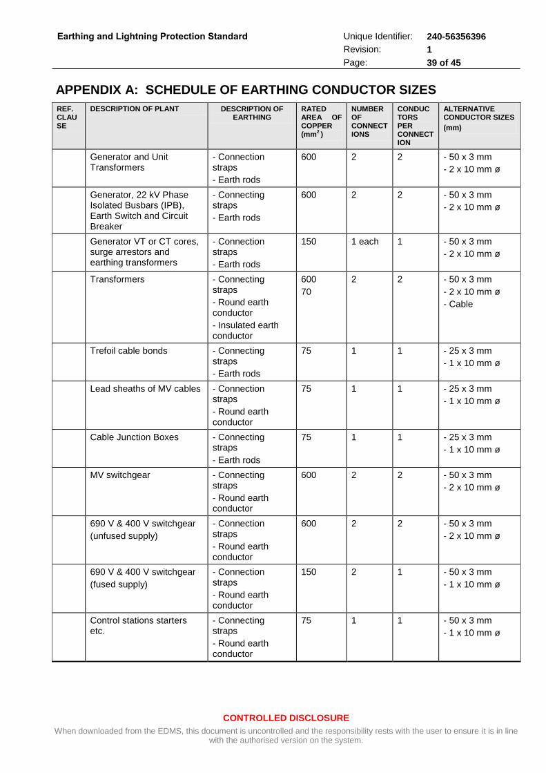
CONTROLLED DISCLOSURE
When downloaded from the EDMS, this document is uncontrolled and the responsibility rests with the user to ensure it is in line with the authorised version on the system.
Earthing and Lightning Protection Standard
Unique Identifier: 240-56356396
Revision: 1
Page: 39 of 45
APPENDIX A: SCHEDULE OF EARTHING CONDUCTOR SIZES
REF. CLAUSE
DESCRIPTION OF PLANT DESCRIPTION OF EARTHING
RATED AREA OF COPPER (mm
2 )
NUMBER OF CONNECTIONS
CONDUCTORS PER CONNECTION
ALTERNATIVE CONDUCTOR SIZES
(mm)
Generator and Unit Transformers
- Connection straps
- Earth rods
600 2 2 - 50 x 3 mm
- 2 x 10 mm ø
Generator, 22 kV Phase Isolated Busbars (IPB), Earth Switch and Circuit Breaker
- Connecting straps
- Earth rods
600
2
2
- 50 x 3 mm
- 2 x 10 mm ø
Generator VT or CT cores, surge arrestors and earthing transformers
- Connection straps
- Earth rods
150
1 each
1 - 50 x 3 mm
- 2 x 10 mm ø
Transformers - Connecting straps
- Round earth conductor
- Insulated earth conductor
600
70
2 2 - 50 x 3 mm
- 2 x 10 mm ø
- Cable
Trefoil cable bonds - Connecting straps
- Earth rods
75
1
1
- 25 x 3 mm
- 1 x 10 mm ø
Lead sheaths of MV cables - Connection straps
- Round earth conductor
75 1 1 - 25 x 3 mm
- 1 x 10 mm ø
Cable Junction Boxes - Connecting straps
- Earth rods
75 1 1 - 25 x 3 mm
- 1 x 10 mm ø
MV switchgear
- Connecting straps
- Round earth conductor
600
2
2
- 50 x 3 mm
- 2 x 10 mm ø
690 V & 400 V switchgear
(unfused supply)
- Connection straps
- Round earth conductor
600
2
2
- 50 x 3 mm
- 2 x 10 mm ø
690 V & 400 V switchgear
(fused supply)
- Connection straps
- Round earth conductor
150 2 1 - 50 x 3 mm
- 1 x 10 mm ø
Control stations starters etc.
- Connecting straps
- Round earth conductor
75 1
1
- 50 x 3 mm
- 1 x 10 mm ø
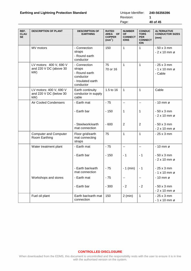
CONTROLLED DISCLOSURE
When downloaded from the EDMS, this document is uncontrolled and the responsibility rests with the user to ensure it is in line with the authorised version on the system.
Earthing and Lightning Protection Standard
Unique Identifier: 240-56356396
Revision: 1
Page: 40 of 45
REF. CLAUSE
DESCRIPTION OF PLANT DESCRIPTION OF EARTHING
RATED AREA OF COPPER (mm
2 )
NUMBER OF CONNECTIONS
CONDUCTORS PER CONNECTION
ALTERNATIVE CONDUCTOR SIZES
(mm)
MV motors - Connection straps
- Round earth conductor
150
1
1
- 50 x 3 mm
- 2 x 10 mm ø
LV motors: 400 V, 690 V and 220 V DC (above 30 kW)
- Connection straps
- Round earth conductor
- Insulated earth conductor
75
70 or 16
1
1
- 25 x 3 mm
- 1 x 10 mm ø
- Cable
LV motors: 400 V, 690 V and 220 V DC (below 30 kW)
Earth continuity conductor in supply cable
1.5 to 16 1 1 Cable
Air Cooled Condensers - Earth mat
- Earth bar
- Steelwork/earth mat connection
- 75
- 150
- 600
--
1
2
--
1
2
- 10 mm ø
- 50 x 3 mm
- 2 x 10 mm ø
- 50 x 3 mm
- 2 x 10 mm ø
Computer and Computer Room Earthing
Floor grid/earth mat connecting straps
75 1 1 - 25 x 3 mm
Water treatment plant - Earth mat
- Earth bar
- Earth bar/earth mat connection
- 75
- 150
- 75
--
- 1
- 1 (min)
--
- 1
- 1
- 10 mm ø
- 50 x 3 mm
- 2 x 10 mm ø
- 25 x 3 mm
- 1 x 10 mm ø
Workshops and stores - Earth mat
- Earth bar
- 75
- 300
--
- 2
--
- 2
- 10 mm ø
- 50 x 3 mm
- 2 x 10 mm ø
Fuel oil plant Earth bar/earth mat connection
150 2 (min) 1 - 25 x 3 mm
- 1 x 10 mm ø
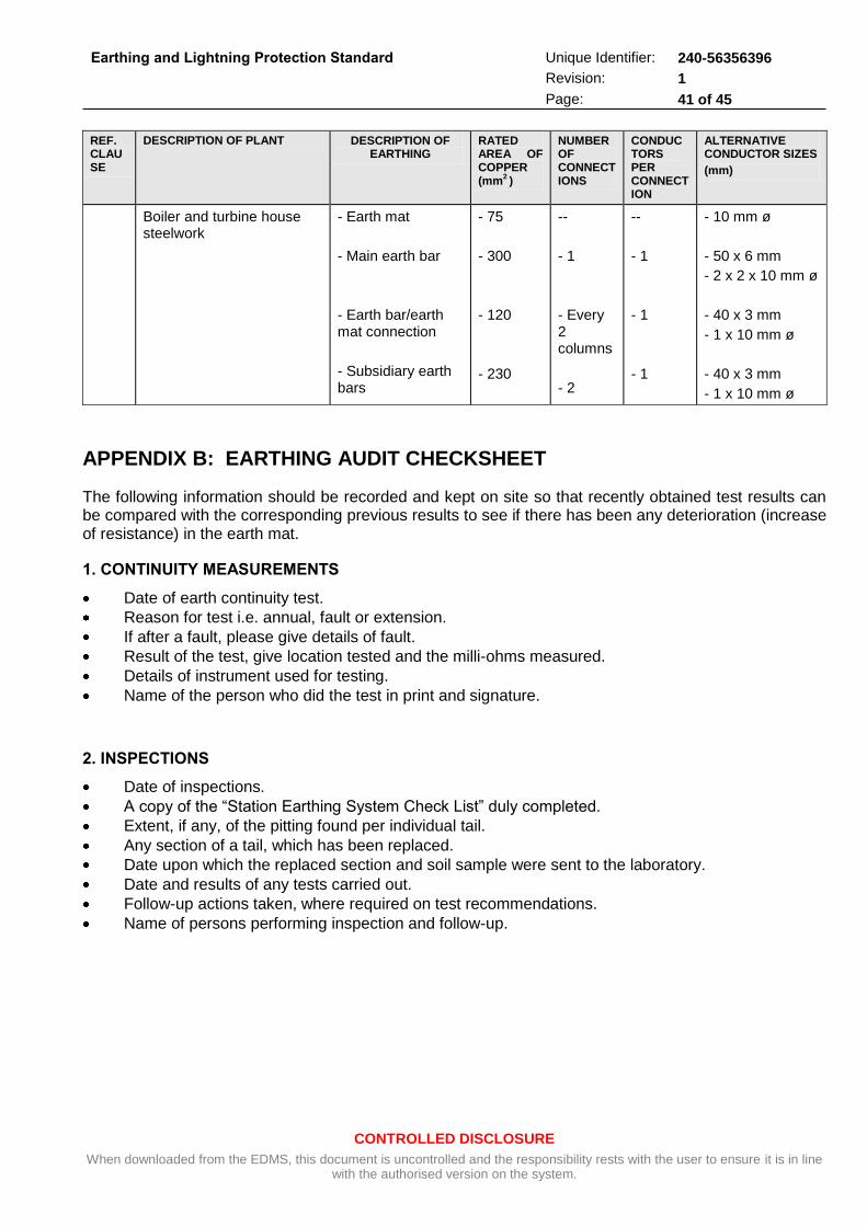
CONTROLLED DISCLOSURE
When downloaded from the EDMS, this document is uncontrolled and the responsibility rests with the user to ensure it is in line with the authorised version on the system.
Earthing and Lightning Protection Standard
Unique Identifier: 240-56356396
Revision: 1
Page: 41 of 45
REF. CLAUSE
DESCRIPTION OF PLANT DESCRIPTION OF EARTHING
RATED AREA OF COPPER (mm
2 )
NUMBER OF CONNECTIONS
CONDUCTORS PER CONNECTION
ALTERNATIVE CONDUCTOR SIZES
(mm)
Boiler and turbine house steelwork
- Earth mat
- Main earth bar
- Earth bar/earth mat connection
- Subsidiary earth bars
- 75
- 300
- 120
- 230
--
- 1
- Every 2 columns
- 2
--
- 1
- 1
- 1
- 10 mm ø
- 50 x 6 mm
- 2 x 2 x 10 mm ø
- 40 x 3 mm
- 1 x 10 mm ø
- 40 x 3 mm
- 1 x 10 mm ø
APPENDIX B: EARTHING AUDIT CHECKSHEET
The following information should be recorded and kept on site so that recently obtained test results can be compared with the corresponding previous results to see if there has been any deterioration (increase of resistance) in the earth mat.
1. CONTINUITY MEASUREMENTS
Date of earth continuity test.
Reason for test i.e. annual, fault or extension.
If after a fault, please give details of fault.
Result of the test, give location tested and the milli-ohms measured.
Details of instrument used for testing.
Name of the person who did the test in print and signature.
2. INSPECTIONS
Date of inspections.
A copy of the “Station Earthing System Check List” duly completed.
Extent, if any, of the pitting found per individual tail.
Any section of a tail, which has been replaced.
Date upon which the replaced section and soil sample were sent to the laboratory.
Date and results of any tests carried out.
Follow-up actions taken, where required on test recommendations.
Name of persons performing inspection and follow-up.
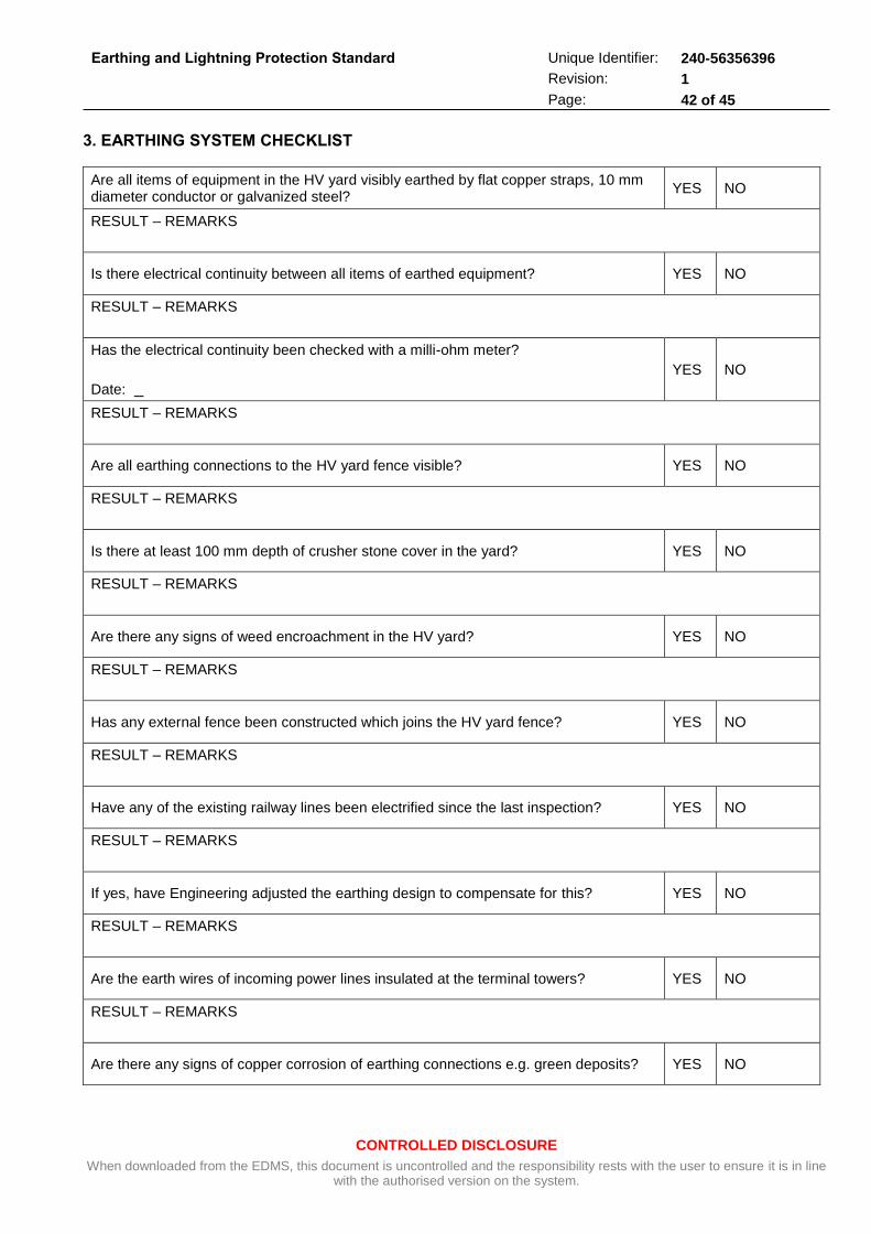
CONTROLLED DISCLOSURE
When downloaded from the EDMS, this document is uncontrolled and the responsibility rests with the user to ensure it is in line with the authorised version on the system.
Earthing and Lightning Protection Standard
Unique Identifier: 240-56356396
Revision: 1
Page: 42 of 45
3. EARTHING SYSTEM CHECKLIST
Are all items of equipment in the HV yard visibly earthed by flat copper straps, 10 mm diameter conductor or galvanized steel?
YES NO
RESULT – REMARKS
Is there electrical continuity between all items of earthed equipment? YES NO
RESULT – REMARKS
Has the electrical continuity been checked with a milli-ohm meter?
Date:
YES NO
RESULT – REMARKS
Are all earthing connections to the HV yard fence visible? YES NO
RESULT – REMARKS
Is there at least 100 mm depth of crusher stone cover in the yard? YES NO
RESULT – REMARKS
Are there any signs of weed encroachment in the HV yard? YES NO
RESULT – REMARKS
Has any external fence been constructed which joins the HV yard fence? YES NO
RESULT – REMARKS
Have any of the existing railway lines been electrified since the last inspection? YES NO
RESULT – REMARKS
If yes, have Engineering adjusted the earthing design to compensate for this? YES NO
RESULT – REMARKS
Are the earth wires of incoming power lines insulated at the terminal towers? YES NO
RESULT – REMARKS
Are there any signs of copper corrosion of earthing connections e.g. green deposits? YES NO
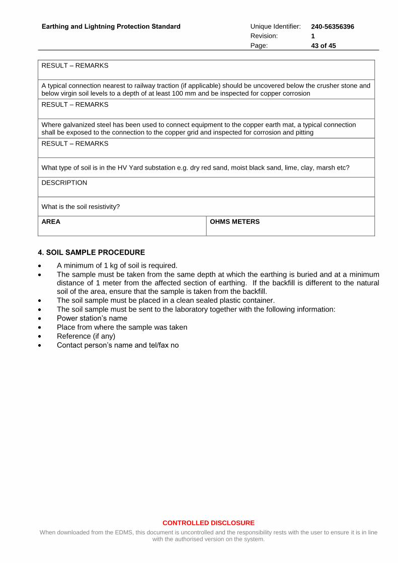
CONTROLLED DISCLOSURE
When downloaded from the EDMS, this document is uncontrolled and the responsibility rests with the user to ensure it is in line with the authorised version on the system.
Earthing and Lightning Protection Standard
Unique Identifier: 240-56356396
Revision: 1
Page: 43 of 45
RESULT – REMARKS
A typical connection nearest to railway traction (if applicable) should be uncovered below the crusher stone and below virgin soil levels to a depth of at least 100 mm and be inspected for copper corrosion
RESULT – REMARKS
Where galvanized steel has been used to connect equipment to the copper earth mat, a typical connection shall be exposed to the connection to the copper grid and inspected for corrosion and pitting
RESULT – REMARKS
What type of soil is in the HV Yard substation e.g. dry red sand, moist black sand, lime, clay, marsh etc?
DESCRIPTION
What is the soil resistivity?
AREA
OHMS METERS
4. SOIL SAMPLE PROCEDURE
A minimum of 1 kg of soil is required.
The sample must be taken from the same depth at which the earthing is buried and at a minimum distance of 1 meter from the affected section of earthing. If the backfill is different to the natural soil of the area, ensure that the sample is taken from the backfill.
The soil sample must be placed in a clean sealed plastic container.
The soil sample must be sent to the laboratory together with the following information:
Power station’s name
Place from where the sample was taken
Reference (if any)
Contact person’s name and tel/fax no
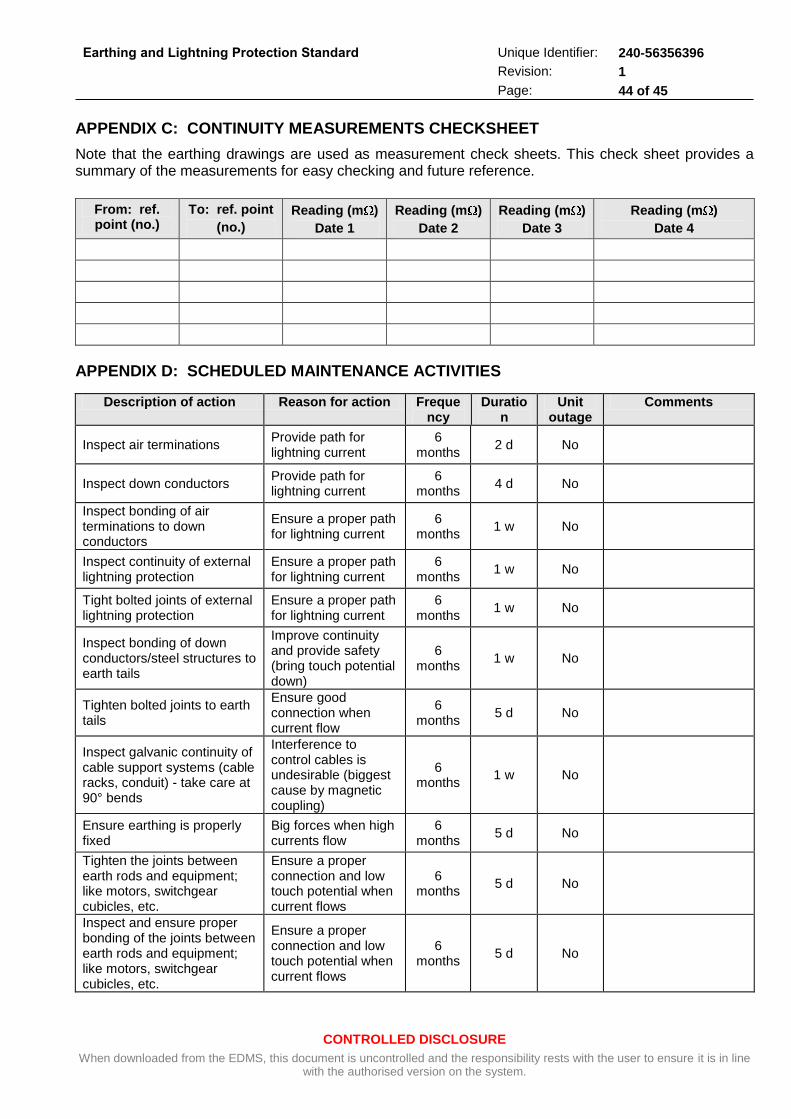
CONTROLLED DISCLOSURE
When downloaded from the EDMS, this document is uncontrolled and the responsibility rests with the user to ensure it is in line with the authorised version on the system.
Earthing and Lightning Protection Standard
Unique Identifier: 240-56356396
Revision: 1
Page: 44 of 45
APPENDIX C: CONTINUITY MEASUREMENTS CHECKSHEET
Note that the earthing drawings are used as measurement check sheets. This check sheet provides a summary of the measurements for easy checking and future reference.
From: ref. point (no.)
To: ref. point
(no.)
Reading (m )
Date 1
Reading (m )
Date 2
Reading (m )
Date 3
Reading (m )
Date 4
APPENDIX D: SCHEDULED MAINTENANCE ACTIVITIES
Description of action Reason for action Frequency
Duration
Unit outage
Comments
Inspect air terminations Provide path for lightning current
6 months
2 d No
Inspect down conductors Provide path for lightning current
6 months
4 d No
Inspect bonding of air terminations to down conductors
Ensure a proper path for lightning current
6 months
1 w No
Inspect continuity of external lightning protection
Ensure a proper path for lightning current
6 months
1 w No
Tight bolted joints of external lightning protection
Ensure a proper path for lightning current
6 months
1 w No
Inspect bonding of down conductors/steel structures to earth tails
Improve continuity and provide safety (bring touch potential down)
6 months
1 w No
Tighten bolted joints to earth tails
Ensure good connection when current flow
6 months
5 d No
Inspect galvanic continuity of cable support systems (cable racks, conduit) - take care at 90° bends
Interference to control cables is undesirable (biggest cause by magnetic coupling)
6 months
1 w No
Ensure earthing is properly fixed
Big forces when high currents flow
6 months
5 d No
Tighten the joints between earth rods and equipment; like motors, switchgear cubicles, etc.
Ensure a proper connection and low touch potential when current flows
6 months
5 d No
Inspect and ensure proper bonding of the joints between earth rods and equipment; like motors, switchgear cubicles, etc.
Ensure a proper connection and low touch potential when current flows
6 months
5 d No
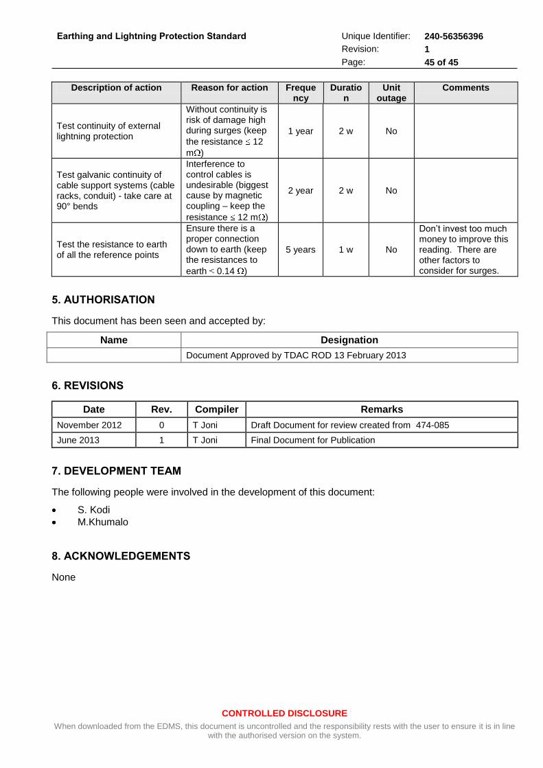
CONTROLLED DISCLOSURE
When downloaded from the EDMS, this document is uncontrolled and the responsibility rests with the user to ensure it is in line with the authorised version on the system.
Earthing and Lightning Protection Standard
Unique Identifier: 240-56356396
Revision: 1
Page: 45 of 45
Description of action Reason for action Frequency
Duration
Unit outage
Comments
Test continuity of external lightning protection
Without continuity is risk of damage high during surges (keep
the resistance 12
m )
1 year 2 w No
Test galvanic continuity of cable support systems (cable racks, conduit) - take care at 90° bends
Interference to control cables is undesirable (biggest cause by magnetic coupling – keep the
resistance 12 m )
2 year 2 w No
Test the resistance to earth of all the reference points
Ensure there is a proper connection down to earth (keep the resistances to
earth 0.14 )
5 years 1 w No
Don’t invest too much money to improve this reading. There are other factors to consider for surges.
5. AUTHORISATION
This document has been seen and accepted by:
Name Designation
Document Approved by TDAC ROD 13 February 2013
6. REVISIONS
Date Rev. Compiler Remarks
November 2012 0 T Joni Draft Document for review created from 474-085
June 2013 1 T Joni Final Document for Publication
7. DEVELOPMENT TEAM
The following people were involved in the development of this document:
S. Kodi
M.Khumalo
8. ACKNOWLEDGEMENTS
None