Embed Size (px)
Citation preview
Bedienungsanleitung
3-20x50 PMII Ultra Short LPSeite 1 von 24
Schmidt & Bender GmbH & Co. KG • Am Grossacker 42 • D-35444 Biebertal Tel. +49 (0) 64 09-81 15-0 • Fax +49 (0) 64 09-81 15-11 [email protected] • www.schmidt-bender.de
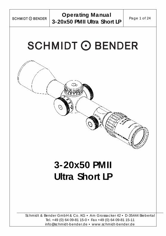
3-20x50 PMII Ultra Short LP


Bedienungsanleitung
3-20x50 PMII Ultra Short LP Seite 3 von 24
Schmidt & Bender GmbH & Co. KG • Am Grossacker 42 • D-35444 Biebertal Tel. +49 (0) 64 09-81 15-0 • Fax +49 (0) 64 09-81 15-11 [email protected] • www.schmidt-bender.de
1. Beschreibung ................................................................................................. 5
1.1 Einleitung .................................................................................................... 5
1.2 Sicherheitshinweise ................................................................................... 5
2. Technische Daten .......................................................................................... 6
2.1 Allgemeine Daten .................................................................................... 6
2.2 Abmessungen ........................................................................................... 7
3. Lieferumfang und optionales Zubehör ......................................................... 8
4. Bedienung ...................................................................................................... 9
4.1 Okulareinstellung .................................................................................... 10
4.2 Parallaxeausgleich ................................................................................. 11
4.3 Bedienung der Beleuchtung ................................................................ 12
4.4 Batteriewechsel ....................................................................................... 13
4.5 Verwendung des Absehens bei der Entfernungsschätzung ........... 14
5. Schusskorrektur ............................................................................................ 16
5.1 Funktionen des Höhen- und Seitenturms ............................................ 16
5.2 Nullen der Türme ..................................................................................... 18
5.3 Höhenverstellung .................................................................................... 20
5.4 Seitenverstellung ..................................................................................... 21
6. Wartung und Pflege ..................................................................................... 22
6.1 Verwendung der Schutzkappen .......................................................... 22
6.2 Reinigung und Wartung ........................................................................ 22
6.3 Lagertemperatur .................................................................................... 22
7. Garantie- und Werksbescheinigung ......................................................... 23

Bedienungsanleitung
3-20x50 PMII Ultra Short LP Seite 5 von 24
Schmidt & Bender GmbH & Co. KG • Am Grossacker 42 • D-35444 Biebertal Tel. +49 (0) 64 09-81 15-0 • Fax +49 (0) 64 09-81 15-11 [email protected] • www.schmidt-bender.de
1. Beschreibung
1.1 Einleitung
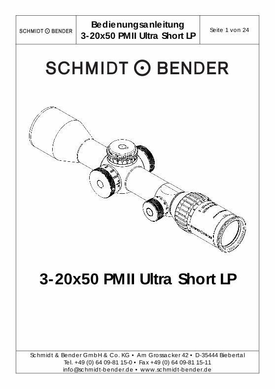
Zielfernrohre der Modellreihe PMII wurden für die besonderen Anforderungen des Präzisionsschießens entwickelt. Sie dienen in Qualität und Funktion sowohl der Erreichung schießsportlicher Höchstleistungen als auch der Erfüllung dienstlicher, oftmals ausgesprochen schwieriger und verantwortungsvoller Aufgaben. Die strikte Beachtung nachstehender Gebrauchshinweise ist Voraussetzung für eine langjährige Nutzung.
1.2 Sicherheitshinweise
Um Augenverletzungen zu vermeiden, blicken Sie niemals mit dem Zielfernrohr in die Sonne oder ungeschützt in Laserlichtquellen. Unterlassen Sie eigene Eingriffe am Zielfernrohr. Reparaturen sollten ausschließlich von Schmidt & Bender oder durch von uns autorisierte Fachbetriebe durchgeführt werden. Schützen Sie Ihr Zielfernrohr vor Stößen außerhalb des regulären Gebrauchs. Vermeiden Sie, das Zielfernrohr unnötig lange direkter Sonneneinwirkung auszusetzen; bei hochgradiger und länger andauernder Sonneneinstrahlung entstehen im Rohrinneren extrem hohe Temperaturen, die dem Zielfernrohr schaden können. Waffe und Zielfernrohr müssen durch eine qualifizierte Montage zu einer Einheit verbunden werden. Wir empfehlen daher, diese Arbeit von einem Fachbetrieb durchführen zu lassen. Eine perfekte Montage ist unabdingbare Voraussetzung für einwandfreie Nutzung. Besondere Aufmerksamkeit sollte hierbei auf ausreichenden Augenabstand gerichtet werden. Dadurch wird das volle Sehfeld für den Schützen erschlossen und Augenverletzungen werden in Folge des Rückstoßes der Waffe vermieden.

Bedienungsanleitung
3-20x50 PMII Ultra Short LP Seite 6 von 24
Schmidt & Bender GmbH & Co. KG • Am Grossacker 42 • D-35444 Biebertal Tel. +49 (0) 64 09-81 15-0 • Fax +49 (0) 64 09-81 15-11 [email protected] • www.schmidt-bender.de
2. Technische Daten
2.1 Allgemeine Daten
Vergrößerung - 3x – 20x Objektivdurchmesser - 50 (mm) Sehfeld - 13,0 – 2,1 (m/100m) Austrittspupille - 11,4 – 2,5 (mm) Augenabstand - 90 (mm) Dämmerungszahl - 12,2 – 31,6 Transmission - 90 (%) Dioptrienverstellung - +2 bis -3 (dpt) Parallaxeausgleich - 25 - ∞ (m) Gewicht - 903 (g) Absehenbildebene - 1. oder 2.
Bedienungsanleitung
3-20x50 PMII Ultra Short LP Seite 7 von 24
Schmidt & Bender GmbH & Co. KG • Am Grossacker 42 • D-35444 Biebertal Tel. +49 (0) 64 09-81 15-0 • Fax +49 (0) 64 09-81 15-11 [email protected] • www.schmidt-bender.de
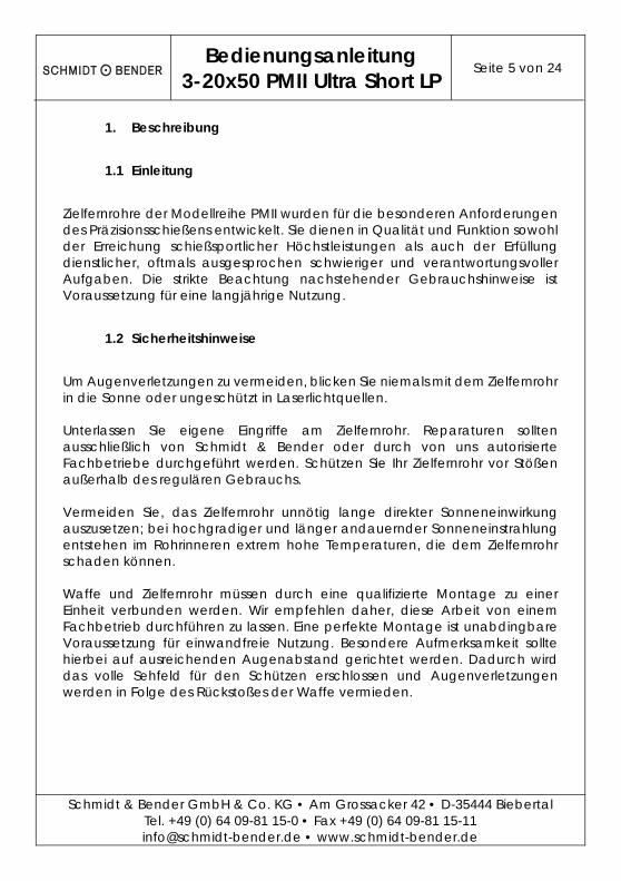
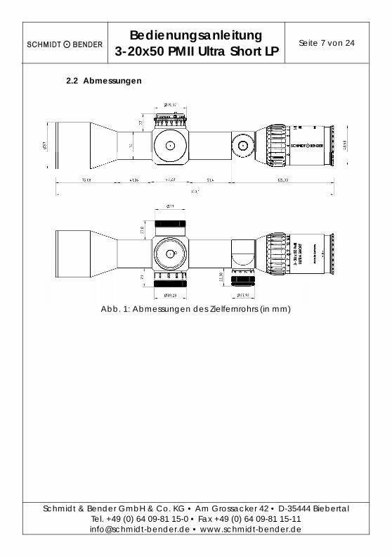
2.2 Abmessungen
Abb. 1: Abmessungen des Zielfernrohrs (in mm)
Bedienungsanleitung
3-20x50 PMII Ultra Short LP Seite 8 von 24
Schmidt & Bender GmbH & Co. KG • Am Grossacker 42 • D-35444 Biebertal Tel. +49 (0) 64 09-81 15-0 • Fax +49 (0) 64 09-81 15-11 [email protected] • www.schmidt-bender.de
3. Lieferumfang und optionales Zubehör
Einige der unten aufgeführten Zubehörteile sind bereits Bestandteil des Lieferumfanges. Die anderen, mit (*) gekennzeichneten Zubehörteile können unter der angegeben Artikelnummer optional bestellt werden. Cleaning Kit - 971-90 Objektiv Schutzdeckel (*) - 971-641 Wabenfilter (*) - 971-61 Okular Schutzdeckel (*) - 971-642 Sonnenblende schwarz(*) - 917-45150 Sonnenblende RAL 8000 (*) - 917-45150-45 Sonnenblende Pantone (*) - 917-45150-46 Gelbfilter (*) - 971-6441 Graufilter (*) - 971-6442 2mm Innensechskantschlüssel - 400-23 Transporttasche Schwarz (klein) (*) - 971-064 Transporttasche RAL 8000 (klein) (*) - 971-065 Registrierkarte, Antwortkarte und Zielfernrohretikett
Bedienungsanleitung
3-20x50 PMII Ultra Short LP Seite 9 von 24
Schmidt & Bender GmbH & Co. KG • Am Grossacker 42 • D-35444 Biebertal Tel. +49 (0) 64 09-81 15-0 • Fax +49 (0) 64 09-81 15-11 [email protected] • www.schmidt-bender.de
4. Bedienung
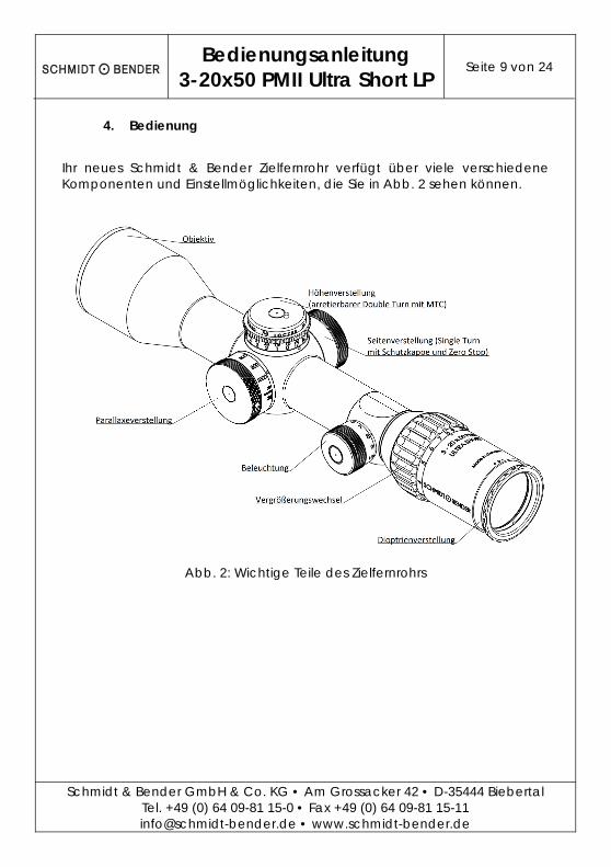
Ihr neues Schmidt & Bender Zielfernrohr verfügt über viele verschiedene Komponenten und Einstellmöglichkeiten, die Sie in Abb. 2 sehen können.
Abb. 2: Wichtige Teile des Zielfernrohrs
Bedienungsanleitung
3-20x50 PMII Ultra Short LP Seite 10 von 24
Schmidt & Bender GmbH & Co. KG • Am Grossacker 42 • D-35444 Biebertal Tel. +49 (0) 64 09-81 15-0 • Fax +49 (0) 64 09-81 15-11 [email protected] • www.schmidt-bender.de
4.1 Okulareinstellung
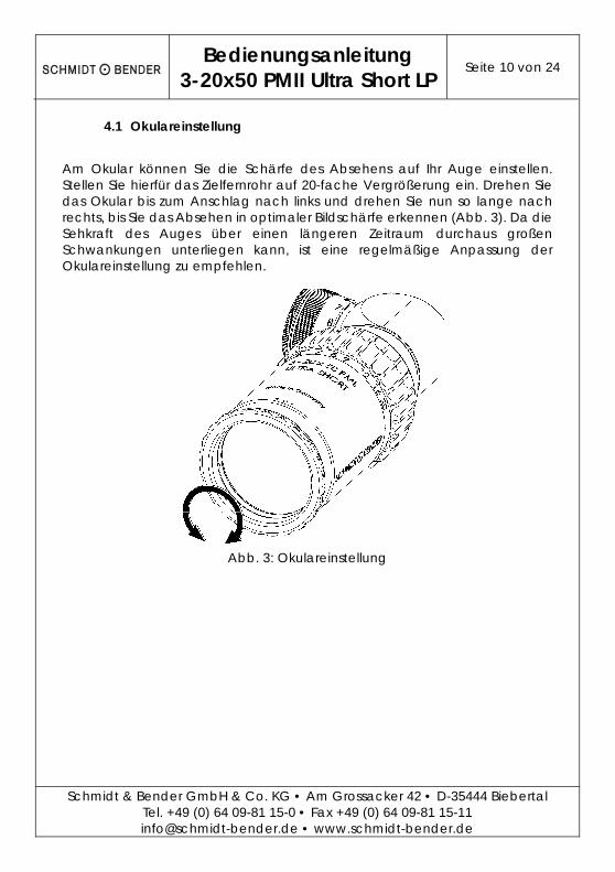
Am Okular können Sie die Schärfe des Absehens auf Ihr Auge einstellen. Stellen Sie hierfür das Zielfernrohr auf 20-fache Vergrößerung ein. Drehen Sie das Okular bis zum Anschlag nach links und drehen Sie nun so lange nach rechts, bis Sie das Absehen in optimaler Bildschärfe erkennen (Abb. 3). Da die Sehkraft des Auges über einen längeren Zeitraum durchaus großen Schwankungen unterliegen kann, ist eine regelmäßige Anpassung der Okulareinstellung zu empfehlen.
Abb. 3: Okulareinstellung
Bedienungsanleitung
3-20x50 PMII Ultra Short LP Seite 11 von 24
Schmidt & Bender GmbH & Co. KG • Am Grossacker 42 • D-35444 Biebertal Tel. +49 (0) 64 09-81 15-0 • Fax +49 (0) 64 09-81 15-11 [email protected] • www.schmidt-bender.de
4.2 Parallaxeausgleich
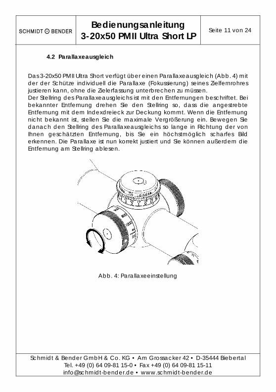
Das 3-20x50 PMII Ultra Short verfügt über einen Parallaxeausgleich (Abb. 4) mit der der Schütze individuell die Parallaxe (Fokussierung) seines Zielfernrohres justieren kann, ohne die Zielerfassung unterbrechen zu müssen. Der Stellring des Parallaxeausgleichs ist mit den Entfernungen beschriftet. Bei bekannter Entfernung drehen Sie den Stellring so, dass die angestrebte Entfernung mit dem Indexdreieck zur Deckung kommt. Wenn die Entfernung nicht bekannt ist, stellen Sie die maximale Vergrößerung ein. Bewegen Sie danach den Stellring des Parallaxeausgleichs so lange in Richtung der von Ihnen geschätzten Entfernung, bis Sie ein höchstmöglich scharfes Bild erkennen. Die Parallaxe ist nun korrekt justiert und Sie können außerdem die Entfernung am Stellring ablesen.
Abb. 4: Parallaxeeinstellung
Bedienungsanleitung
3-20x50 PMII Ultra Short LP Seite 12 von 24
Schmidt & Bender GmbH & Co. KG • Am Grossacker 42 • D-35444 Biebertal Tel. +49 (0) 64 09-81 15-0 • Fax +49 (0) 64 09-81 15-11 [email protected] • www.schmidt-bender.de
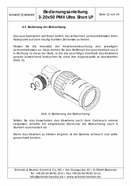
4.3 Bedienung der Beleuchtung
Das Leuchtabsehen soll Ihnen helfen, bei schlechten Lichtverhältnissen Ihren Haltepunkt auf dem häufig dunklen Ziel besser zu finden. Passen Sie die Intensität der Absehenbeleuchtung den jeweiligen Lichtverhältnissen an. Dazu drehen Sie den Stellknopf der Leuchteinheit von 0 in Richtung 11 bis zu der Stufe, in der die Leuchtfigur innerhalb des Absehens gerade ausreichend beleuchtet ist, ohne Ihre Augenpupille zu überstrahlen (Abb. 5).
Abb. 5: Bedienung der Beleuchtung
Sollten Sie das Ausschalten des Absehens nach dem Gebrauch einmal vergessen, schaltet ein eingebauter Microchip die Beleuchtung nach 6 Stunden automatisch ab. Wenn das Absehen zu blinken beginnt, ist die Batterie schwach und sollte gewechselt werden.
Bedienungsanleitung
3-20x50 PMII Ultra Short LP Seite 13 von 24
Schmidt & Bender GmbH & Co. KG • Am Grossacker 42 • D-35444 Biebertal Tel. +49 (0) 64 09-81 15-0 • Fax +49 (0) 64 09-81 15-11 [email protected] • www.schmidt-bender.de
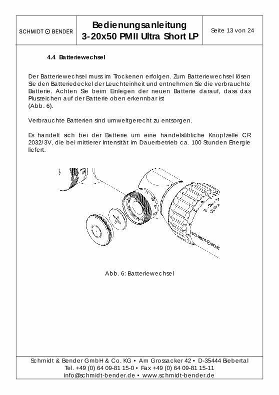
4.4 Batteriewechsel
Der Batteriewechsel muss im Trockenen erfolgen. Zum Batteriewechsel lösen Sie den Batteriedeckel der Leuchteinheit und entnehmen Sie die verbrauchte Batterie. Achten Sie beim Einlegen der neuen Batterie darauf, dass das Pluszeichen auf der Batterie oben erkennbar ist (Abb. 6). Verbrauchte Batterien sind umweltgerecht zu entsorgen. Es handelt sich bei der Batterie um eine handelsübliche Knopfzelle CR 2032/3V, die bei mittlerer Intensität im Dauerbetrieb ca. 100 Stunden Energie liefert.
Abb. 6: Batteriewechsel
Bedienungsanleitung
3-20x50 PMII Ultra Short LP Seite 14 von 24
Schmidt & Bender GmbH & Co. KG • Am Grossacker 42 • D-35444 Biebertal Tel. +49 (0) 64 09-81 15-0 • Fax +49 (0) 64 09-81 15-11 [email protected] • www.schmidt-bender.de
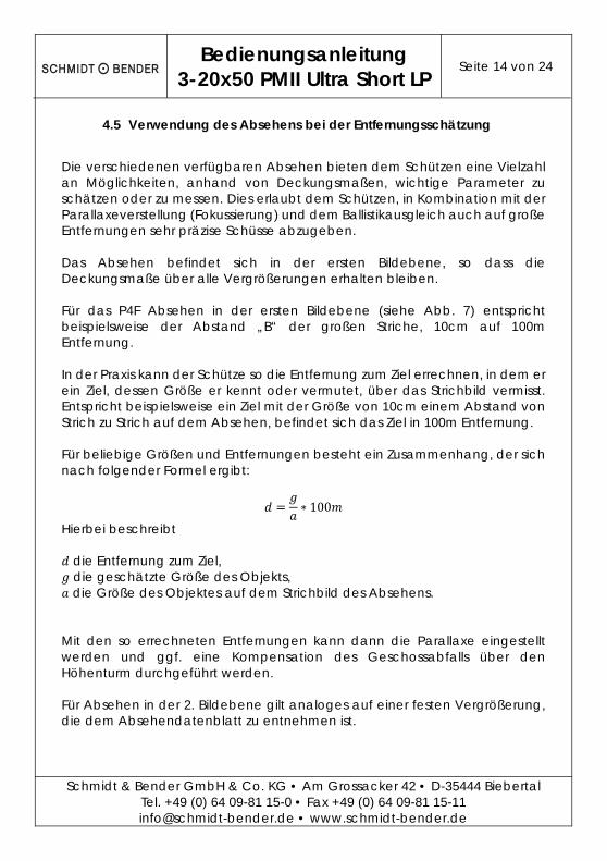
4.5 Verwendung des Absehens bei der Entfernungsschätzung
Die verschiedenen verfügbaren Absehen bieten dem Schützen eine Vielzahl an Möglichkeiten, anhand von Deckungsmaßen, wichtige Parameter zu schätzen oder zu messen. Dies erlaubt dem Schützen, in Kombination mit der Parallaxeverstellung (Fokussierung) und dem Ballistikausgleich auch auf große Entfernungen sehr präzise Schüsse abzugeben. Das Absehen befindet sich in der ersten Bildebene, so dass die Deckungsmaße über alle Vergrößerungen erhalten bleiben. Für das P4F Absehen in der ersten Bildebene (siehe Abb. 7) entspricht beispielsweise der Abstand „B“ der großen Striche, 10cm auf 100m Entfernung. In der Praxis kann der Schütze so die Entfernung zum Ziel errechnen, in dem er ein Ziel, dessen Größe er kennt oder vermutet, über das Strichbild vermisst. Entspricht beispielsweise ein Ziel mit der Größe von 10cm einem Abstand von Strich zu Strich auf dem Absehen, befindet sich das Ziel in 100m Entfernung. Für beliebige Größen und Entfernungen besteht ein Zusammenhang, der sich nach folgender Formel ergibt:
∗ 100
Hierbei beschreibt
die Entfernung zum Ziel, die geschätzte Größe des Objekts, die Größe des Objektes auf dem Strichbild des Absehens.
Mit den so errechneten Entfernungen kann dann die Parallaxe eingestellt werden und ggf. eine Kompensation des Geschossabfalls über den Höhenturm durchgeführt werden. Für Absehen in der 2. Bildebene gilt analoges auf einer festen Vergrößerung, die dem Absehendatenblatt zu entnehmen ist.
Bedienungsanleitung
3-20x50 PMII Ultra Short LP Seite 15 von 24
Schmidt & Bender GmbH & Co. KG • Am Grossacker 42 • D-35444 Biebertal Tel. +49 (0) 64 09-81 15-0 • Fax +49 (0) 64 09-81 15-11 [email protected] • www.schmidt-bender.de
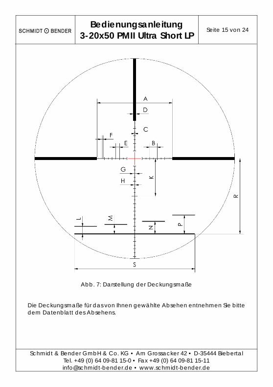
Abb. 7: Darstellung der Deckungsmaße
Die Deckungsmaße für das von Ihnen gewählte Absehen entnehmen Sie bitte dem Datenblatt des Absehens.
Bedienungsanleitung
3-20x50 PMII Ultra Short LP Seite 16 von 24
Schmidt & Bender GmbH & Co. KG • Am Grossacker 42 • D-35444 Biebertal Tel. +49 (0) 64 09-81 15-0 • Fax +49 (0) 64 09-81 15-11 [email protected] • www.schmidt-bender.de
5. Schusskorrektur
5.1 Funktionen des Höhen- und Seitenturms
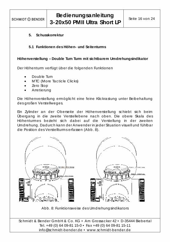
Höhenverstellung – Double Turn Turm mit sichtbarem Umdrehungsindikator
Der Höhenturm verfügt über die folgenden Funktionen
Double Turn MTC (More Tacticle Clicks) Zero Stop Arretierung
Die Höhenverstellung ermöglicht eine feine Klickrastung unter Beibehaltung des großen Verstellweges.
Ein Zylinder an der Oberseite der Höhenverstellung schiebt sich beim Übergang in die zweite Verstellebene nach oben. Die obere Skala des Höhenturmes bezieht sich dabei auf die Verstellung in der zweiten Umdrehung. Dadurch kann der Anwender in jeder Situation visuell und fühlbar die Position des Verstellturms erfassen (Abb. 8).
Abb. 8: Funktionsweise des Umdrehungsindikators
Bedienungsanleitung
3-20x50 PMII Ultra Short LP Seite 17 von 24
Schmidt & Bender GmbH & Co. KG • Am Grossacker 42 • D-35444 Biebertal Tel. +49 (0) 64 09-81 15-0 • Fax +49 (0) 64 09-81 15-11 [email protected] • www.schmidt-bender.de
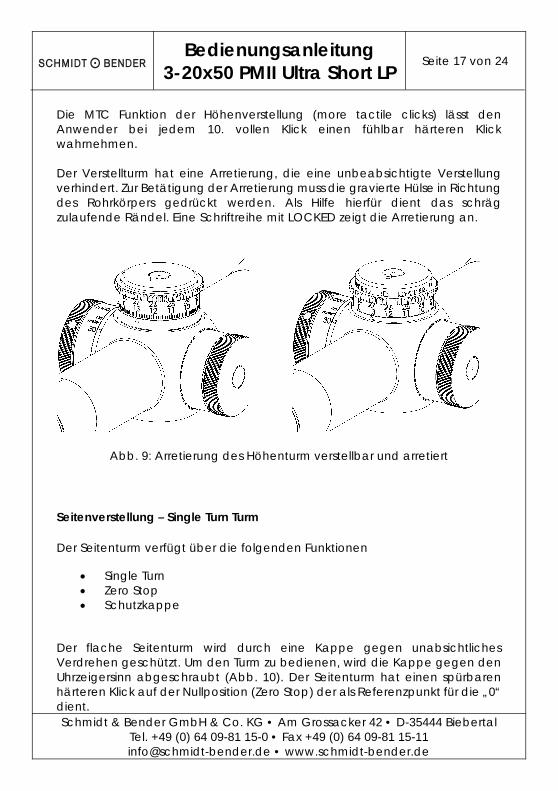
Die MTC Funktion der Höhenverstellung (more tactile clicks) lässt den Anwender bei jedem 10. vollen Klick einen fühlbar härteren Klick wahrnehmen. Der Verstellturm hat eine Arretierung, die eine unbeabsichtigte Verstellung verhindert. Zur Betätigung der Arretierung muss die gravierte Hülse in Richtung des Rohrkörpers gedrückt werden. Als Hilfe hierfür dient das schräg zulaufende Rändel. Eine Schriftreihe mit LOCKED zeigt die Arretierung an.
Abb. 9: Arretierung des Höhenturm verstellbar und arretiert
Seitenverstellung – Single Turn Turm
Der Seitenturm verfügt über die folgenden Funktionen
Single Turn Zero Stop Schutzkappe
Der flache Seitenturm wird durch eine Kappe gegen unabsichtliches Verdrehen geschützt. Um den Turm zu bedienen, wird die Kappe gegen den Uhrzeigersinn abgeschraubt (Abb. 10). Der Seitenturm hat einen spürbaren härteren Klick auf der Nullposition (Zero Stop) der als Referenzpunkt für die „0“ dient.

Bedienungsanleitung
3-20x50 PMII Ultra Short LP Seite 18 von 24
Schmidt & Bender GmbH & Co. KG • Am Grossacker 42 • D-35444 Biebertal Tel. +49 (0) 64 09-81 15-0 • Fax +49 (0) 64 09-81 15-11 [email protected] • www.schmidt-bender.de
Abb. 10:Entfernen der Kappe
5.2 Nullen der Türme
Bei der ersten Benutzung oder falls sich durch Wartungs-, Reparaturarbeiten oder sonstige Veränderungen am Waffensystem die Treffpunktlage verändern sollte, muss die Verstellung kalibriert werden. Im Auslieferungszustand ist das Zielfernrohr auf die optische Mitte eingestellt. Zum Kalibrieren muss eine Gruppe von Schüssen auf eine Zielscheibe in der gewünschten Referenzentfernung für die Null abgegeben werden. Die Abweichungen, die sich vom Schussbild zur Mitte bzw. dem Haltepunkt auf der Zielscheibe ergeben, müssen nun entsprechend dem in den Punkten 5.3 und 5.4 beschriebenen Vorgehen korrigiert werden. Vergewissern Sie sich anschließend durch eine erneute Abgabe von mehreren Schüssen, dass das Schussbild nun in der Mitte der Zielscheibe bzw. dem Haltepunkt liegt. Ggf. bitte den Korrekturvorgang wiederholen. Nach dem Einschießen müssen die Türme wieder auf Null zurückgesetzt werden.
Bedienungsanleitung
3-20x50 PMII Ultra Short LP Seite 19 von 24
Schmidt & Bender GmbH & Co. KG • Am Grossacker 42 • D-35444 Biebertal Tel. +49 (0) 64 09-81 15-0 • Fax +49 (0) 64 09-81 15-11 [email protected] • www.schmidt-bender.de
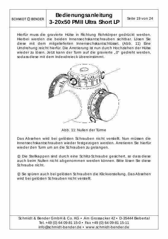
Hierfür muss die gravierte Hülse in Richtung Rohrkörper gedrückt werden. Hierbei werden die beiden Innensechskantschrauben sichtbar. Lösen Sie diese mit dem mitgelieferten Innensechskantschlüssel. (Abb. 11) Eine Umdrehung reicht hierfür. Die Arretierung ist nun durch Hochziehen der Hülse wieder zu lösen. Jetzt kann der Turm auf die gravierte „0“ gedreht werden, sodass diese mit dem Indexdreieck übereinstimmt.
Abb. 11: Nullen der Türme
Das Absehen wird bei gelösten Schrauben nicht verstellt. Nun müssen die Innensechskantschrauben wieder festgezogen werden. Arretieren Sie hierfür wieder den Turm um an die Schrauben zu gelangen. Die Stellkappen sind durch eine Schlitz-Schraube gesichert, so dass diese auch beim Nullen nicht abgenommen werden können. Bitte lösen Sie diese Schraube nicht. Sie spüren auch bei gelösten Schrauben die Klickverstellung. Das Absehen wird bei gelösten Schrauben nicht verstellt.
Bedienungsanleitung
3-20x50 PMII Ultra Short LP Seite 20 von 24
Schmidt & Bender GmbH & Co. KG • Am Grossacker 42 • D-35444 Biebertal Tel. +49 (0) 64 09-81 15-0 • Fax +49 (0) 64 09-81 15-11 [email protected] • www.schmidt-bender.de
5.3 Höhenverstellung
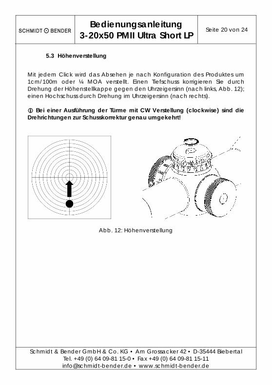
Mit jedem Click wird das Absehen je nach Konfiguration des Produktes um 1cm/100m oder ¼ MOA verstellt. Einen Tiefschuss korrigieren Sie durch Drehung der Höhenstellkappe gegen den Uhrzeigersinn (nach links, Abb. 12); einen Hochschuss durch Drehung im Uhrzeigersinn (nach rechts). Bei einer Ausführung der Türme mit CW Verstellung (clockwise) sind die Drehrichtungen zur Schusskorrektur genau umgekehrt!
Abb. 12: Höhenverstellung
Bedienungsanleitung
3-20x50 PMII Ultra Short LP Seite 21 von 24
Schmidt & Bender GmbH & Co. KG • Am Grossacker 42 • D-35444 Biebertal Tel. +49 (0) 64 09-81 15-0 • Fax +49 (0) 64 09-81 15-11 [email protected] • www.schmidt-bender.de
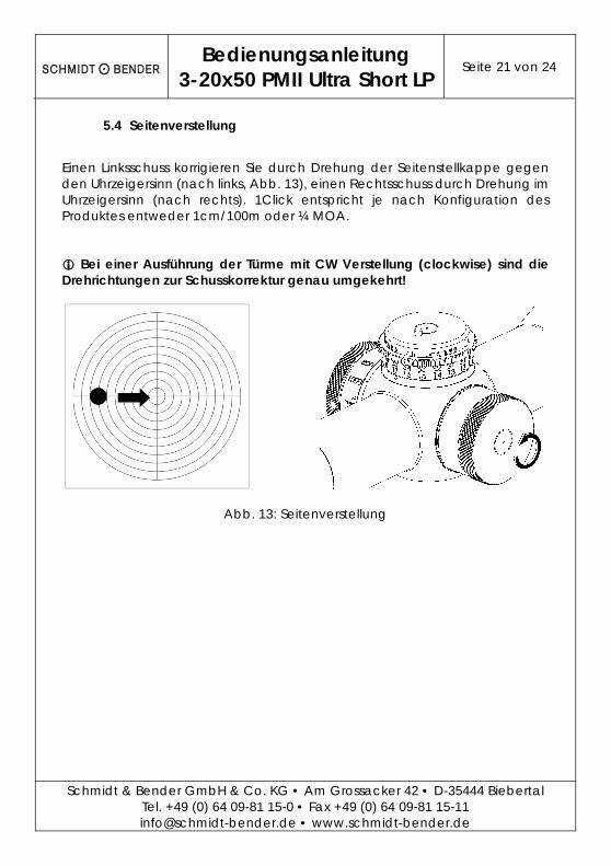
5.4 Seitenverstellung
Einen Linksschuss korrigieren Sie durch Drehung der Seitenstellkappe gegen den Uhrzeigersinn (nach links, Abb. 13), einen Rechtsschuss durch Drehung im Uhrzeigersinn (nach rechts). 1Click entspricht je nach Konfiguration des Produktes entweder 1cm/100m oder ¼ MOA. Bei einer Ausführung der Türme mit CW Verstellung (clockwise) sind die Drehrichtungen zur Schusskorrektur genau umgekehrt!
Abb. 13: Seitenverstellung
Bedienungsanleitung
3-20x50 PMII Ultra Short LP Seite 22 von 24
Schmidt & Bender GmbH & Co. KG • Am Grossacker 42 • D-35444 Biebertal Tel. +49 (0) 64 09-81 15-0 • Fax +49 (0) 64 09-81 15-11 [email protected] • www.schmidt-bender.de
6. Wartung und Pflege
6.1 Verwendung der Schutzkappen
Zum Schutz vor äußeren Einflüssen und Witterungsbedingungen wie Sand, Schmutz, Regen, Schnee usw. sollten die Okular- und Objektivschutzkappe nach jedem Gebrauch des Zielfernrohres geschlossen werden. Vor jedem Schießen sollte darauf geachtet werden, dass die Verschlusskappen geöffnet sind, am Zielfernrohr anliegen und eingerastet sind. Dies verhindert ein unkontrolliertes Schwingen der Verschlusskappen beim Schießen.
6.2 Reinigung und Wartung
Die Schmidt & Bender Zielfernrohre der PMII-Modellreihe benötigen keine besondere Wartung und Pflege. Alle Metallteile sind mit einer harten Oberfläche versehen, die grundsätzlich pflegeleicht und extrem kratzfest ist. Zur Reinigung verwenden Sie hier ein sauberes und ggf. leicht angefeuchtetes Putztuch. Zur Reinigung der Optik benutzen Sie bitte das von Schmidt & Bender beigefügte Reinigungsset. Optikoberflächen sollten Sie vor einem evtl. Sauberwischen zunächst mit dem Pinsel von grobem Staub und Schmutzpartikeln befreien. Leichte Verschmutzungen können dann mit dem Optik-Reinigungstuch entfernt werden. Hauchen Sie die Optik vor dem Reinigen leicht an, dies erleichtert den Reinigungsvorgang mit dem Optiktuch. Grobe Verschmutzungen können entweder mit der im Reinigungsset befindlichen Reinigungsflüssigkeit oder mit lauwarmem, entspanntem Wasser entfernt werden. Trockenes Reiben auf den Außenflächen der Linsen müssen Sie auf jeden Fall vermeiden, dies kann die wertvolle Vergütungsschicht zerstören.
6.3 Lagertemperatur
Der Temperaturbereich zum Lagern des Zielfernrohrs reicht von -55 bis +70°C.

Bedienungsanleitung
3-20x50 PMII Ultra Short LP Seite 23 von 24
Schmidt & Bender GmbH & Co. KG • Am Grossacker 42 • D-35444 Biebertal Tel. +49 (0) 64 09-81 15-0 • Fax +49 (0) 64 09-81 15-11 [email protected] • www.schmidt-bender.de
7. Garantie- und Werksbescheinigung
Die TÜV Cert-Zertifizierungsstelle der TÜV Anlagentechnik GmbH (Unternehmensgruppe TÜV Rheinland Berlin Brandenburg) bescheinigt gemäß TÜV Cert-Verfahren, dass das Unternehmen Schmidt & Bender GmbH & Co. KG, Biebertal, Deutschland für den Geltungsbereich Konstruktion, Herstellung, Vertrieb und Service feinmechanisch-optischer Geräte, Hauptprodukt: Zielfernrohre, ein Qualitätsmanagementsystem eingeführt hat und anwendet; die Forderungen der DIN EN ISO 9001 (#Registration 01 100 67280) sind erfüllt. Alle Teile wurden eingehend gemäß den Anforderungen des vorab genannten Systems geprüft und entsprechen diesen in allen Punkten. Garantie-Gewährleistung: Offizielle gesetzliche Garantie-Gewährleistung: 2 Jahre (gem. EU-Richtlinien) Schmidt & Bender GmbH & Co. KG Am Grossacker 42 35444 Biebertal Deutschland Kontakt:
Schmidt & Bender GmbH & Co. KG • Am Grossacker 42 • D-35444 Biebertal Tel. +49 (0) 64 09-81 15-0 • Fax +49 (0) 64 09-81 15-11 [email protected] • www.schmidt-bender.de

Operating Manual
3-20x50 PMII Ultra Short LP Page 1 of 24
Schmidt & Bender GmbH & Co. KG • Am Grossacker 42 • D-35444 Biebertal Tel. +49 (0) 64 09-81 15-0 • Fax +49 (0) 64 09-81 15-11 [email protected] • www.schmidt-bender.de
3-20x50 PMII Ultra Short LP

Operating Manual
3-20x50 PMII Ultra Short LP Page 3 of 24
Schmidt & Bender GmbH & Co. KG • Am Grossacker 42 • D-35444 Biebertal Tel. +49 (0) 64 09-81 15-0 • Fax +49 (0) 64 09-81 15-11 [email protected] • www.schmidt-bender.de
1. Scope description .......................................................................................... 5
1.1 Introduction ............................................................................................... 5
1.2 Safety instructions ..................................................................................... 5
2. Technical data ............................................................................................... 6
2.1 General data ............................................................................................. 6
2.2 Dimensions ................................................................................................. 7
3. Accessories / Scope of supply ..................................................................... 8
4. Operating instructions ................................................................................... 9
4.1 Adjusting the image focus with the diopter adjustment of the eyepiece ................................................................................................................ 10
4.2 Parallax adjustment ................................................................................ 11
4.3 Illumination control ................................................................................. 12
4.4 Changing the battery ............................................................................ 13
4.5 Using the reticle for the distance estimation ..................................... 14
5. Point of impact correction .......................................................................... 16
5.1 Using the elevation turret and the windage turret ........................... 16
5.2 Preliminary adjusting and fine adjusting when sighting in ............... 18
5.3 Elevation adjustment ............................................................................. 20
5.4 Windage adjustment ............................................................................. 21
6. Maintenance ................................................................................................ 22
6.1 Using the scope covers .......................................................................... 22
6.2 Care and maintenance ........................................................................ 22
6.3 Storage temperature ............................................................................. 22
7. Warranty certificate ..................................................................................... 23

Operating Manual
3-20x50 PMII Ultra Short LP Page 5 of 24
Schmidt & Bender GmbH & Co. KG • Am Grossacker 42 • D-35444 Biebertal Tel. +49 (0) 64 09-81 15-0 • Fax +49 (0) 64 09-81 15-11 [email protected] • www.schmidt-bender.de
1. Scope description
1.1 Introduction
The Schmidt & Bender PM II series scopes are designed to meet the unique challenges of high precision shooting. Their quality and function make it possible to achieve exceptional shooting results as well as to fulfill the critical and demanding needs of official, law enforcement and tactical applications. Strict observation of the following operating instructions is prerequisite for successful long-term use.
1.2 Safety instructions
Never look into the sun or into laser light with the scope. This may cause serious eye injuries. Do not tamper with the scope. Any repairs beyond the maintenance described in the maintenance manual should only be performed by Schmidt & Bender or by other specialists authorized by Schmidt & Bender. Protect the scope against shocks beyond normal use. Avoid unnecessary long exposure of the scope to direct sunlight; intense and excessive sun radiation will cause extremely high temperatures inside the tube which may be detrimental to the scope. The scope must be properly mounted to the firearm by a qualified specialist. Perfect mounting is an essential requirement for maximum accuracy and efficient functioning of the firearm and the scope. Be sure to assume the proper firing position and keep a correct eye relief in order to obtain an optimal full field of view and to avoid any injuries due to the recoil of the weapon.
Operating Manual
3-20x50 PMII Ultra Short LP Page 6 of 24
Schmidt & Bender GmbH & Co. KG • Am Grossacker 42 • D-35444 Biebertal Tel. +49 (0) 64 09-81 15-0 • Fax +49 (0) 64 09-81 15-11 [email protected] • www.schmidt-bender.de
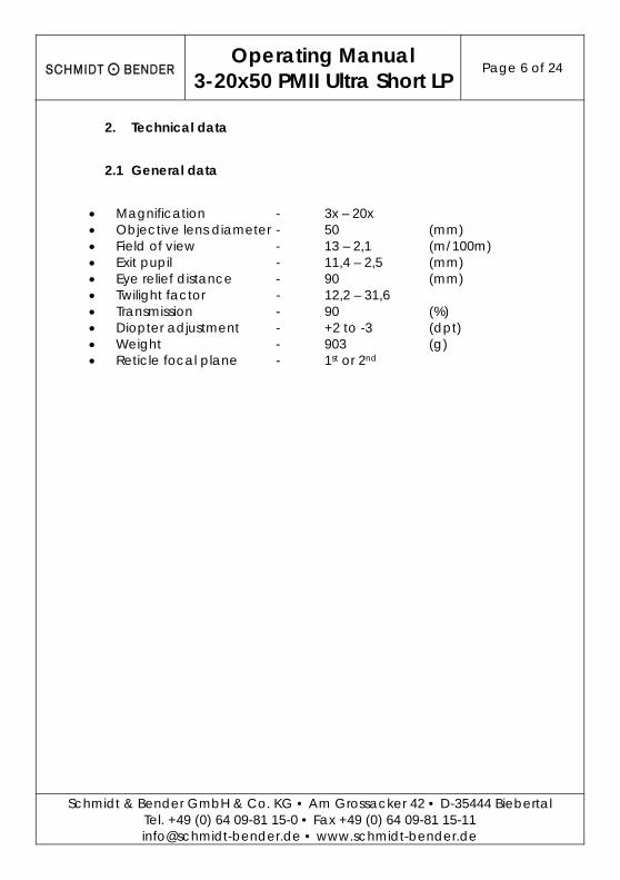
2. Technical data
2.1 General data
Magnification - 3x – 20x Objective lens diameter - 50 (mm) Field of view - 13 – 2,1 (m/100m) Exit pupil - 11,4 – 2,5 (mm) Eye relief distance - 90 (mm) Twilight factor - 12,2 – 31,6 Transmission - 90 (%) Diopter adjustment - +2 to -3 (dpt) Weight - 903 (g) Reticle focal plane - 1st or 2nd

Operating Manual
3-20x50 PMII Ultra Short LP Page 7 of 24
Schmidt & Bender GmbH & Co. KG • Am Grossacker 42 • D-35444 Biebertal Tel. +49 (0) 64 09-81 15-0 • Fax +49 (0) 64 09-81 15-11 [email protected] • www.schmidt-bender.de
2.2 Dimensions
Illustr. 1: Dimensions from the scope (in mm)
Operating Manual
3-20x50 PMII Ultra Short LP Page 8 of 24
Schmidt & Bender GmbH & Co. KG • Am Grossacker 42 • D-35444 Biebertal Tel. +49 (0) 64 09-81 15-0 • Fax +49 (0) 64 09-81 15-11 [email protected] • www.schmidt-bender.de
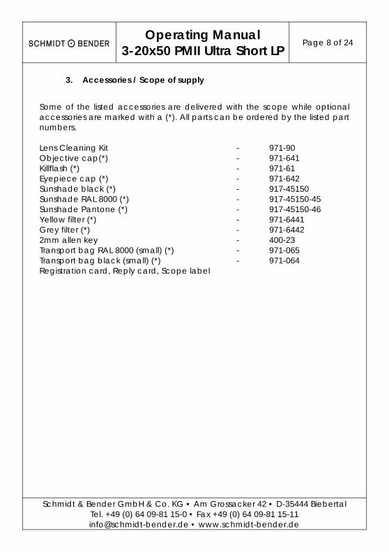
3. Accessories / Scope of supply
Some of the listed accessories are delivered with the scope while optional accessories are marked with a (*). All parts can be ordered by the listed part numbers. Lens Cleaning Kit - 971-90 Objective cap(*) - 971-641 Killflash (*) - 971-61 Eyepiece cap (*) - 971-642 Sunshade black (*) - 917-45150 Sunshade RAL 8000 (*) - 917-45150-45 Sunshade Pantone (*) - 917-45150-46 Yellow filter (*) - 971-6441 Grey filter (*) - 971-6442 2mm allen key - 400-23 Transport bag RAL 8000 (small) (*) - 971-065 Transport bag black (small) (*) - 971-064 Registration card, Reply card, Scope label
Operating Manual
3-20x50 PMII Ultra Short LP Page 9 of 24
Schmidt & Bender GmbH & Co. KG • Am Grossacker 42 • D-35444 Biebertal Tel. +49 (0) 64 09-81 15-0 • Fax +49 (0) 64 09-81 15-11 [email protected] • www.schmidt-bender.de
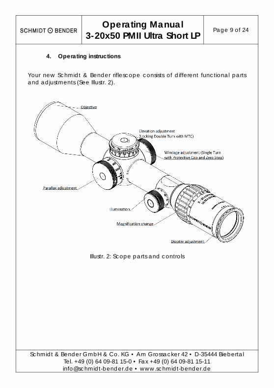
4. Operating instructions
Your new Schmidt & Bender riflescope consists of different functional parts and adjustments (See Illustr. 2).
Illustr. 2: Scope parts and controls

Operating Manual
3-20x50 PMII Ultra Short LP Page 10 of 24
Schmidt & Bender GmbH & Co. KG • Am Grossacker 42 • D-35444 Biebertal Tel. +49 (0) 64 09-81 15-0 • Fax +49 (0) 64 09-81 15-11 [email protected] • www.schmidt-bender.de
4.1 Adjusting the image focus with the diopter adjustment of the eyepiece
The eyepiece provides the adjustment of the reticle focus to the individual eye diopter. Set the scope to the highest magnification. Rotate the eyepiece counterclockwise until it stops. Rotate the eyepiece clockwise until you see a sharp image of the reticle (see Illustr. 3). As the vision of the eye over a prolonged period may very well undergo large fluctuations, regular adjustment of the eyepiece is recommended.
Illustr. 3: Diopter adjustment
Operating Manual
3-20x50 PMII Ultra Short LP Page 11 of 24
Schmidt & Bender GmbH & Co. KG • Am Grossacker 42 • D-35444 Biebertal Tel. +49 (0) 64 09-81 15-0 • Fax +49 (0) 64 09-81 15-11 [email protected] • www.schmidt-bender.de
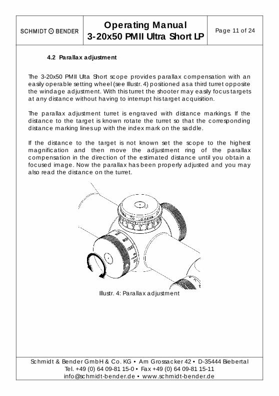
4.2 Parallax adjustment
The 3-20x50 PMII Ulta Short scope provides parallax compensation with an easily operable setting wheel (see Illustr. 4) positioned as a third turret opposite the windage adjustment. With this turret the shooter may easily focus targets at any distance without having to interrupt his target acquisition. The parallax adjustment turret is engraved with distance markings. If the distance to the target is known rotate the turret so that the corresponding distance marking lines up with the index mark on the saddle. If the distance to the target is not known set the scope to the highest magnification and then move the adjustment ring of the parallax compensation in the direction of the estimated distance until you obtain a focused image. Now the parallax has been properly adjusted and you may also read the distance on the turret.
Illustr. 4: Parallax adjustment
Operating Manual
3-20x50 PMII Ultra Short LP Page 12 of 24
Schmidt & Bender GmbH & Co. KG • Am Grossacker 42 • D-35444 Biebertal Tel. +49 (0) 64 09-81 15-0 • Fax +49 (0) 64 09-81 15-11 [email protected] • www.schmidt-bender.de
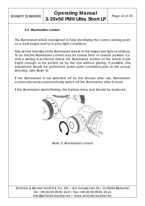
4.3 Illumination control
The illuminated reticle is designed to help identifying the correct aiming point on a dark target and/or in poor light conditions. First, set the intensity of the illuminated reticle to the respective light conditions. To do this the illumination control may be turned from -0- toward position -11- until a setting is achieved where the illuminated portion of the reticle is just bright enough to be picked up by the eye without glaring. If possible, this adjustment should be performed under quiet conditions prior to the actual shooting. (see Illustr. 5). If the illumination is not switched off by the shooter after use, illumination control electronics automatically switch off the illumination after 6 hours. If the illumination starts blinking, the battery is low and should be replaced.
Illustr. 5: Illumination control
Operating Manual
3-20x50 PMII Ultra Short LP Page 13 of 24
Schmidt & Bender GmbH & Co. KG • Am Grossacker 42 • D-35444 Biebertal Tel. +49 (0) 64 09-81 15-0 • Fax +49 (0) 64 09-81 15-11 [email protected] • www.schmidt-bender.de
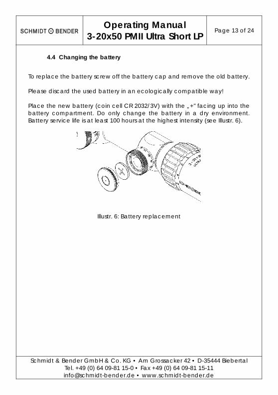
4.4 Changing the battery
To replace the battery screw off the battery cap and remove the old battery. Please discard the used battery in an ecologically compatible way! Place the new battery (coin cell CR 2032/3V) with the „+" facing up into the battery compartment. Do only change the battery in a dry environment. Battery service life is at least 100 hours at the highest intensity (see Illustr. 6).
Illustr. 6: Battery replacement
Operating Manual
3-20x50 PMII Ultra Short LP Page 14 of 24
Schmidt & Bender GmbH & Co. KG • Am Grossacker 42 • D-35444 Biebertal Tel. +49 (0) 64 09-81 15-0 • Fax +49 (0) 64 09-81 15-11 [email protected] • www.schmidt-bender.de
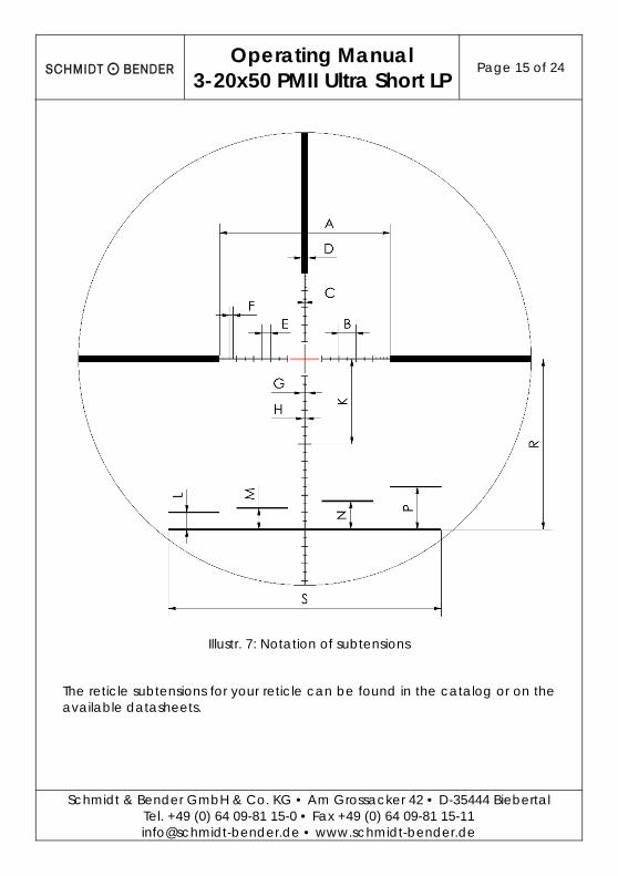
4.5 Using the reticle for the distance estimation
The different available reticles offer a variety of possibilities to estimate or measure important parameters by means of reticle subtensions. This allows the shooter to place highly precise shots even on large distances by use of the estimates, the ballistic compensator and the parallax adjustment. The reticle is in the first focal plane such that the reticle subtensions remain constant on all magnifications. Exemplary for the P4F reticle in the first focal plane (see Illustr. 7) the distance “B” of the large tics corresponds to 10cm/100m. The shooter can thus calculate the distance to a target which size is known by measuring it with the reticle pattern: If a 10cm sized target fits inbetween two large tics, it is positioned in a distance of 100m. For arbitrary object sizes and distances a relation exists according to the following formula:
∗ 100
Whereas
is the distance to the target, is the estimated size of the target, is the size of the target on the reticle pattern.
According to the measured distance, the parallax can be set and the bullet drop can be compensated by the elevation turret. For reticles in the 2nd focal plane analogous estimations and calculations can be made on a certain magnification. This magnification can be obtained from the reticle datasheet.
Operating Manual
3-20x50 PMII Ultra Short LP Page 15 of 24
Schmidt & Bender GmbH & Co. KG • Am Grossacker 42 • D-35444 Biebertal Tel. +49 (0) 64 09-81 15-0 • Fax +49 (0) 64 09-81 15-11 [email protected] • www.schmidt-bender.de
Illustr. 7: Notation of subtensions
The reticle subtensions for your reticle can be found in the catalog or on the available datasheets.
Operating Manual
3-20x50 PMII Ultra Short LP Page 16 of 24
Schmidt & Bender GmbH & Co. KG • Am Grossacker 42 • D-35444 Biebertal Tel. +49 (0) 64 09-81 15-0 • Fax +49 (0) 64 09-81 15-11 [email protected] • www.schmidt-bender.de
5. Point of impact correction
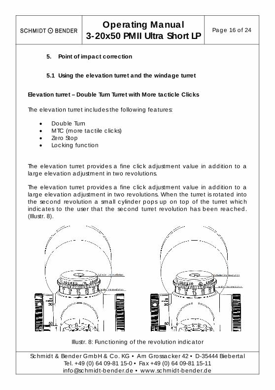
5.1 Using the elevation turret and the windage turret
Elevation turret – Double Turn Turret with More tacticle Clicks
The elevation turret includes the following features:
Double Turn MTC (more tactile clicks) Zero Stop Locking function
The elevation turret provides a fine click adjustment value in addition to a large elevation adjustment in two revolutions.
The elevation turret provides a fine click adjustment value in addition to a large elevation adjustment in two revolutions. When the turret is rotated into the second revolution a small cylinder pops up on top of the turret which indicates to the user that the second turret revolution has been reached. (Illustr. 8).
Illustr. 8: Functioning of the revolution indicator
Operating Manual
3-20x50 PMII Ultra Short LP Page 17 of 24
Schmidt & Bender GmbH & Co. KG • Am Grossacker 42 • D-35444 Biebertal Tel. +49 (0) 64 09-81 15-0 • Fax +49 (0) 64 09-81 15-11 [email protected] • www.schmidt-bender.de
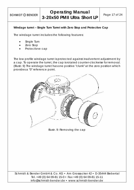
Windage turret – Single Turn Turret with Zero Stop and Protective Cap
The windage turret includes the following features:
Single Turn Zero Stop Protectivve cap
The low profile windage turret is protected against inadvertent adjustment by a cap. To operate the turret, the cap is rotated counter-clockwise for removal. (Illustr. 9) The windage turret has one positive "clunk" at the zero position which provides a "0" reference point.
Illustr. 9: Removing the cap
Operating Manual
3-20x50 PMII Ultra Short LP Page 18 of 24
Schmidt & Bender GmbH & Co. KG • Am Grossacker 42 • D-35444 Biebertal Tel. +49 (0) 64 09-81 15-0 • Fax +49 (0) 64 09-81 15-11 [email protected] • www.schmidt-bender.de
5.2 Preliminary adjusting and fine adjusting when sighting in
When sighting in the scope for the first time, or re-sighting the scope due to service or repair, a test shoot for zeroing the scope must be performed on a 100m distance. Therefore, ensure that the parallax is set to the correct value of 100m and that both elevation and windage turrets are set to “0”. The double turn turret must be set to the first revolution. The centering of the target pattern is then performed according to paragraph 5.3 and 5.4. Lock the elevation turret, loosen the two setscrews on the outside diameter in line with the “LOCKED” indicator using an Allen key (see Illustr. 10). Unlock the turret by pulling up the outer flange and turn the turret until the engraved “0” is indicated by the triangle on the saddle. Lock the elevation turret by pushing down the outer flange with the engraving and tighten the two setscrews with an Allen key. To zero the windage turret, remove the turret cap and loosen the two setscrews. Now turn the turret to zero. Then retighten the screws and screw the turret cap back onto the turret.
Operating Manual
3-20x50 PMII Ultra Short LP Page 19 of 24
Schmidt & Bender GmbH & Co. KG • Am Grossacker 42 • D-35444 Biebertal Tel. +49 (0) 64 09-81 15-0 • Fax +49 (0) 64 09-81 15-11 [email protected] • www.schmidt-bender.de
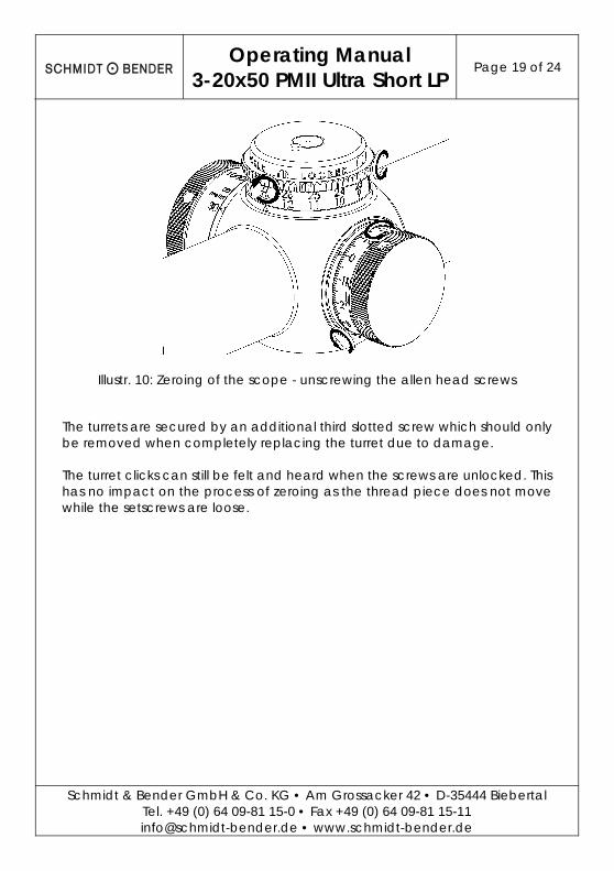
Illustr. 10: Zeroing of the scope - unscrewing the allen head screws
The turrets are secured by an additional third slotted screw which should only be removed when completely replacing the turret due to damage. The turret clicks can still be felt and heard when the screws are unlocked. This has no impact on the process of zeroing as the thread piece does not move while the setscrews are loose.
Operating Manual
3-20x50 PMII Ultra Short LP Page 20 of 24
Schmidt & Bender GmbH & Co. KG • Am Grossacker 42 • D-35444 Biebertal Tel. +49 (0) 64 09-81 15-0 • Fax +49 (0) 64 09-81 15-11 [email protected] • www.schmidt-bender.de
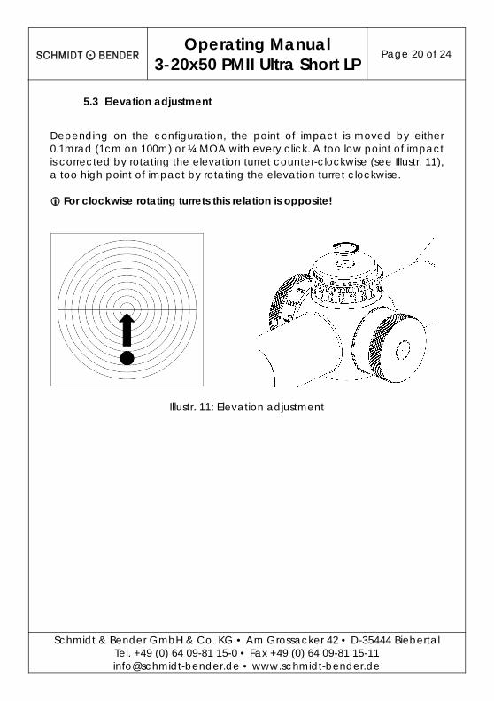
5.3 Elevation adjustment
Depending on the configuration, the point of impact is moved by either 0.1mrad (1cm on 100m) or ¼ MOA with every click. A too low point of impact is corrected by rotating the elevation turret counter-clockwise (see Illustr. 11), a too high point of impact by rotating the elevation turret clockwise. For clockwise rotating turrets this relation is opposite!
Illustr. 11: Elevation adjustment
Operating Manual
3-20x50 PMII Ultra Short LP Page 21 of 24
Schmidt & Bender GmbH & Co. KG • Am Grossacker 42 • D-35444 Biebertal Tel. +49 (0) 64 09-81 15-0 • Fax +49 (0) 64 09-81 15-11 [email protected] • www.schmidt-bender.de
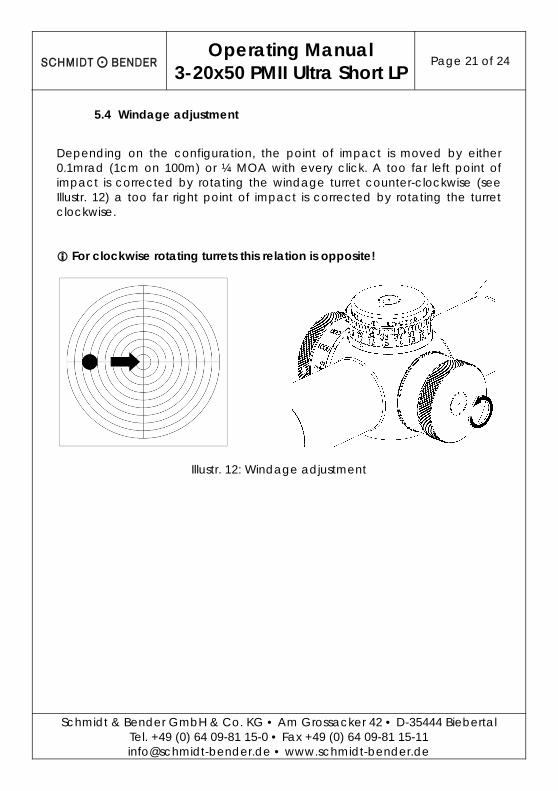
5.4 Windage adjustment
Depending on the configuration, the point of impact is moved by either 0.1mrad (1cm on 100m) or ¼ MOA with every click. A too far left point of impact is corrected by rotating the windage turret counter-clockwise (see Illustr. 12) a too far right point of impact is corrected by rotating the turret clockwise. For clockwise rotating turrets this relation is opposite!
Illustr. 12: Windage adjustment

Operating Manual
3-20x50 PMII Ultra Short LP Page 22 of 24
Schmidt & Bender GmbH & Co. KG • Am Grossacker 42 • D-35444 Biebertal Tel. +49 (0) 64 09-81 15-0 • Fax +49 (0) 64 09-81 15-11 [email protected] • www.schmidt-bender.de
6. Maintenance
6.1 Using the scope covers
To protect the scope and its lenses against adverse environmental conditions like sand, dust, rain, snow, etc., the protective flip-up caps of objective and eyepiece should be closed after every use of the scope. Before shooting, make sure that the caps are open.
6.2 Care and maintenance
Schmidt & Bender PM II scopes do not require any special maintenance. All metal parts have a hard anodized surface that is extremely scratch-resistant and easy to care for. For cleaning outer surfaces, use a clean and, if necessary, a slightly damp cloth. For cleaning the optics use the included Schmidt & Bender cleaning kit. Before wiping the optic’s surfaces, use a dry brush to remove coarse dirt or dust particles. Slight impurities may then be wiped off using an optic’s cleaning cloth. Breathe onto the optic’s surfaces before cleaning them, this helps with the cleaning process. Excessive dirt may be removed using the cleaning liquid included in the cleaning kit. Avoid dry rubbing on the outside optical surfaces, this may harm the precious coatings.
6.3 Storage temperature
The approved temperature range for the storage of the scope is from -55°C to +70°C.

Operating Manual
3-20x50 PMII Ultra Short LP Page 23 of 24
Schmidt & Bender GmbH & Co. KG • Am Grossacker 42 • D-35444 Biebertal Tel. +49 (0) 64 09-81 15-0 • Fax +49 (0) 64 09-81 15-11 [email protected] • www.schmidt-bender.de
7. Warranty certificate
We hereby certify that our Quality Management System has been approved by Unternehmensgruppe TÜV* Rheinland Berlin Brandenburg to the following Quality Management Standard: The TÜV Cert Certification Body of TÜV Anlagentechnik GmbH (Unternehmensgruppe TÜV Rheinland Berlin Brandenburg) certifies in accordance with TÜV Cert procedures that Schmidt & Bender GmbH & Co. KG, Am Grossacker 42, D-35444 Biebertal has established and applies a quality management system for the design, production sales and service of fine mechanical optical instruments. Main product telescopic sights. Proof has been furnished that the requirements according to ISO 9001 (# Registration No. 01 100 67280) are fulfilled. All parts have been thoroughly inspected in accordance with the afore-mentioned Quality Management System and correspond to the requirements of the specifications, drawings, test procedures and standards in all respects. Note *: TÜV means German Association for technical Inspection Guarantee clause: Official legal guarantee period of 2 years (according to the directive of EU) Contact: Schmidt & Bender GmbH & Co. KG • Am Grossacker 42 • D-35444 Biebertal • Germany Tel. +49 (0) 64 09-81 15-0 • Fax +49 (0) 64 09-81 15-11 [email protected] • www.schmidt-bender.de Schmidt & Bender Inc. • 741 Main Street • Claremont, NH 03743 • U.S.A. Tollfree (800)468-3450 • Phone +1(603)287-4830 • Fax (603)287-4832 [email protected]

Schmidt & Bender GmbH & Co. KG • Am Grossacker 42 • D-35444 Biebertal Tel. +49 (0) 64 09-81 15-0 • Fax +49 (0) 64 09-81 15-11
[email protected] • www.schmidt-bender.de Änderungen vorbehalten / Subject to changes , Datum / Date 14.09.2015, Revision 02