Embed Size (px)
DESCRIPTION
Radio Link Control
Citation preview
Section 1 · Module 3 · Page 1
All Rights Reserved © Alcatel-Lucent 20083JK10865AAAAWBZZA Issue 02
Do not delete this graphic elements in here:
1·3All Rights Reserved © Alcatel-Lucent 2008
Module 3Radio Link Control
3JK10865AAAAWBZZA Issue 02
Section 1Radio Algorithms
EVOLIUME-GPRS Radio Algorithms and Parameters Description B10
3FL11830ACAAWBZZA2 Issue 02

Section 1 · Module 3 · Page 2
All Rights Reserved © Alcatel-Lucent 20083JK10865AAAAWBZZA Issue 02
All Rights Reserved © Alcatel-Lucent 2008
EVOLIUM · E-GPRS Radio Algorithms and Parameters Description B10Radio Algorithms · Radio Link Control1 · 3 · 2
Blank Page
This page is left blank intentionally
First editionLast name, first nameYYYY-MM-DD01
RemarksAuthorDateEdition
Document History
Section 1 · Module 3 · Page 3
All Rights Reserved © Alcatel-Lucent 20083JK10865AAAAWBZZA Issue 02
All Rights Reserved © Alcatel-Lucent 2008
EVOLIUM · E-GPRS Radio Algorithms and Parameters Description B10Radio Algorithms · Radio Link Control1 · 3 · 3
Module Objectives
Upon completion of this module, you should be able to:
� Describe the algorithms of Radio Link Control and the related parameters

Section 1 · Module 3 · Page 4
All Rights Reserved © Alcatel-Lucent 20083JK10865AAAAWBZZA Issue 02
All Rights Reserved © Alcatel-Lucent 2008
EVOLIUM · E-GPRS Radio Algorithms and Parameters Description B10Radio Algorithms · Radio Link Control1 · 3 · 4
Module Objectives [cont.]
This page is left blank intentionally
Section 1 · Module 3 · Page 5
All Rights Reserved © Alcatel-Lucent 20083JK10865AAAAWBZZA Issue 02
All Rights Reserved © Alcatel-Lucent 2008
EVOLIUM · E-GPRS Radio Algorithms and Parameters Description B10Radio Algorithms · Radio Link Control1 · 3 · 5
Table of Contents
Switch to notes view! Page
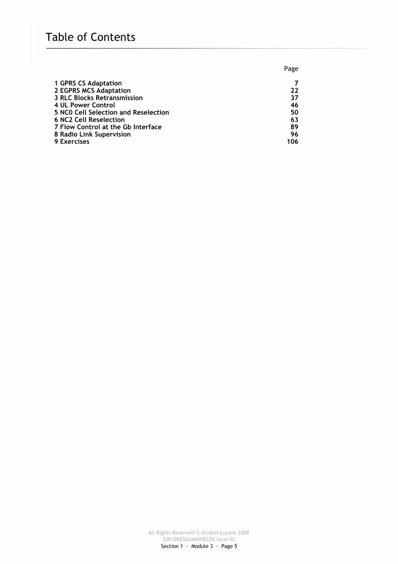
1 GPRS CS Adaptation 72 EGPRS MCS Adaptation 223 RLC Blocks Retransmission 374 UL Power Control 465 NC0 Cell Selection and Reselection 506 NC2 Cell Reselection 637 Flow Control at the Gb Interface 898 Radio Link Supervision 969 Exercises 106

Section 1 · Module 3 · Page 6
All Rights Reserved © Alcatel-Lucent 20083JK10865AAAAWBZZA Issue 02
All Rights Reserved © Alcatel-Lucent 2008
EVOLIUM · E-GPRS Radio Algorithms and Parameters Description B10Radio Algorithms · Radio Link Control1 · 3 · 6
Table of Contents [cont.]
Switch to notes view! Page

Section 1 · Module 3 · Page 7
All Rights Reserved © Alcatel-Lucent 20083JK10865AAAAWBZZA Issue 02
All Rights Reserved © Alcatel-Lucent 2008
EVOLIUM · E-GPRS Radio Algorithms and Parameters Description B10Radio Algorithms · Radio Link Control1 · 3 · 7
1 GPRS CS Adaptation
Section 1 · Module 3 · Page 8
All Rights Reserved © Alcatel-Lucent 20083JK10865AAAAWBZZA Issue 02
All Rights Reserved © Alcatel-Lucent 2008
EVOLIUM · E-GPRS Radio Algorithms and Parameters Description B10Radio Algorithms · Radio Link Control1 · 3 · 8
1 GPRS CS Adaptation
Introduction – GPRS and EGPRS
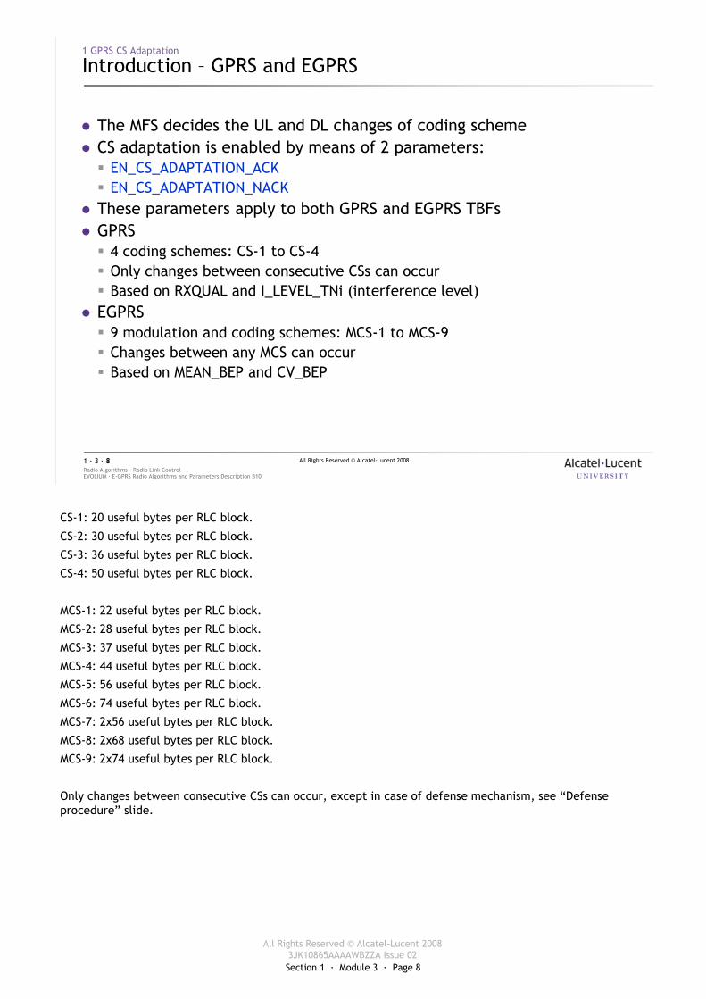
� The MFS decides the UL and DL changes of coding scheme � CS adaptation is enabled by means of 2 parameters:
� EN_CS_ADAPTATION_ACK� EN_CS_ADAPTATION_NACK
� These parameters apply to both GPRS and EGPRS TBFs� GPRS
� 4 coding schemes: CS-1 to CS-4� Only changes between consecutive CSs can occur� Based on RXQUAL and I_LEVEL_TNi (interference level)
� EGPRS� 9 modulation and coding schemes: MCS-1 to MCS-9� Changes between any MCS can occur� Based on MEAN_BEP and CV_BEP
CS-1: 20 useful bytes per RLC block.
CS-2: 30 useful bytes per RLC block.
CS-3: 36 useful bytes per RLC block.
CS-4: 50 useful bytes per RLC block.
MCS-1: 22 useful bytes per RLC block.
MCS-2: 28 useful bytes per RLC block.
MCS-3: 37 useful bytes per RLC block.
MCS-4: 44 useful bytes per RLC block.
MCS-5: 56 useful bytes per RLC block.
MCS-6: 74 useful bytes per RLC block.
MCS-7: 2x56 useful bytes per RLC block.
MCS-8: 2x68 useful bytes per RLC block.
MCS-9: 2x74 useful bytes per RLC block.
Only changes between consecutive CSs can occur, except in case of defense mechanism, see “Defense procedure” slide.
Section 1 · Module 3 · Page 9
All Rights Reserved © Alcatel-Lucent 20083JK10865AAAAWBZZA Issue 02
All Rights Reserved © Alcatel-Lucent 2008
EVOLIUM · E-GPRS Radio Algorithms and Parameters Description B10Radio Algorithms · Radio Link Control1 · 3 · 9
1 GPRS CS Adaptation
Principle
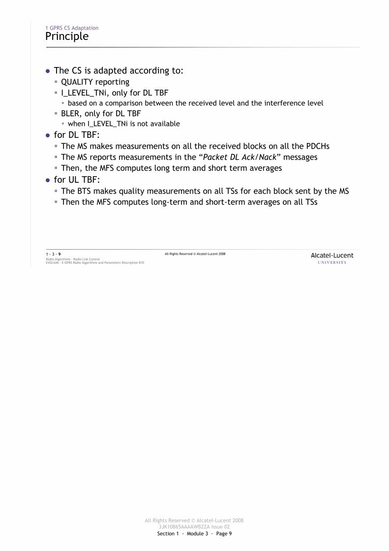
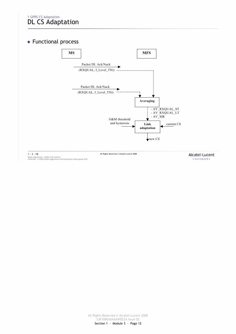
� The CS is adapted according to:� QUALITY reporting� I_LEVEL_TNi, only for DL TBF� based on a comparison between the received level and the interference level
� BLER, only for DL TBF� when I_LEVEL_TNi is not available
� for DL TBF:� The MS makes measurements on all the received blocks on all the PDCHs� The MS reports measurements in the “Packet DL Ack/Nack” messages� Then, the MFS computes long term and short term averages
� for UL TBF:� The BTS makes quality measurements on all TSs for each block sent by the MS� Then the MFS computes long-term and short-term averages on all TSs
Section 1 · Module 3 · Page 10
All Rights Reserved © Alcatel-Lucent 20083JK10865AAAAWBZZA Issue 02
All Rights Reserved © Alcatel-Lucent 2008
EVOLIUM · E-GPRS Radio Algorithms and Parameters Description B10Radio Algorithms · Radio Link Control1 · 3 · 10
1 GPRS CS Adaptation
QUALITY Averaging in the MFS
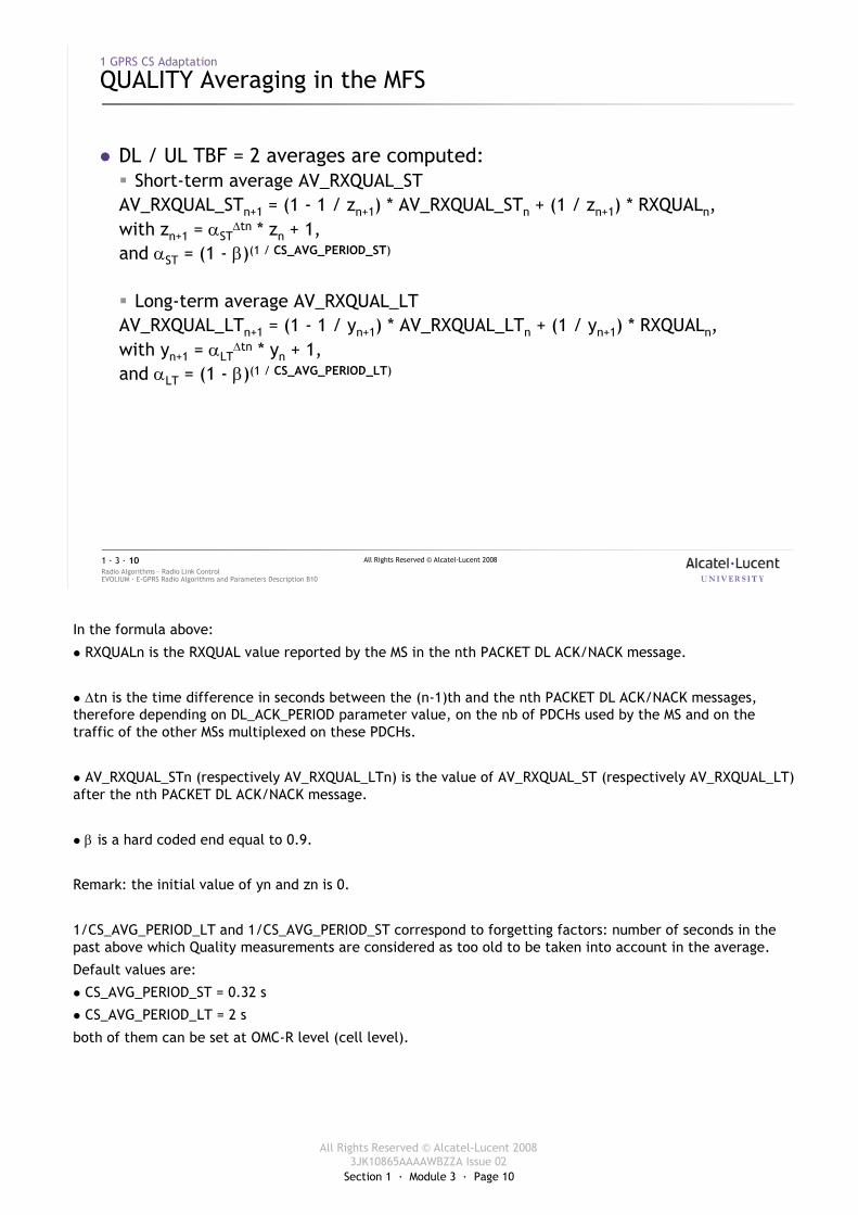
� DL / UL TBF = 2 averages are computed:� Short-term average AV_RXQUAL_STAV_RXQUAL_STn+1 = (1 - 1 / zn+1) * AV_RXQUAL_STn + (1 / zn+1) * RXQUALn,with zn+1 = αST
∆tn * zn + 1,and αST = (1 - β)(1 / CS_AVG_PERIOD_ST)
� Long-term average AV_RXQUAL_LTAV_RXQUAL_LTn+1 = (1 - 1 / yn+1) * AV_RXQUAL_LTn + (1 / yn+1) * RXQUALn,with yn+1 = αLT
∆tn * yn + 1,and αLT = (1 - β)(1 / CS_AVG_PERIOD_LT)
In the formula above:
� RXQUALn is the RXQUAL value reported by the MS in the nth PACKET DL ACK/NACK message.
� ∆tn is the time difference in seconds between the (n-1)th and the nth PACKET DL ACK/NACK messages, therefore depending on DL_ACK_PERIOD parameter value, on the nb of PDCHs used by the MS and on the traffic of the other MSs multiplexed on these PDCHs.
� AV_RXQUAL_STn (respectively AV_RXQUAL_LTn) is the value of AV_RXQUAL_ST (respectively AV_RXQUAL_LT) after the nth PACKET DL ACK/NACK message.
� β is a hard coded end equal to 0.9.
Remark: the initial value of yn and zn is 0.
1/CS_AVG_PERIOD_LT and 1/CS_AVG_PERIOD_ST correspond to forgetting factors: number of seconds in the past above which Quality measurements are considered as too old to be taken into account in the average.
Default values are:
� CS_AVG_PERIOD_ST = 0.32 s
� CS_AVG_PERIOD_LT = 2 s
both of them can be set at OMC-R level (cell level).
Section 1 · Module 3 · Page 11
All Rights Reserved © Alcatel-Lucent 20083JK10865AAAAWBZZA Issue 02
All Rights Reserved © Alcatel-Lucent 2008
EVOLIUM · E-GPRS Radio Algorithms and Parameters Description B10Radio Algorithms · Radio Link Control1 · 3 · 11
1 GPRS CS Adaptation
AV_SIR Computation in the MFS
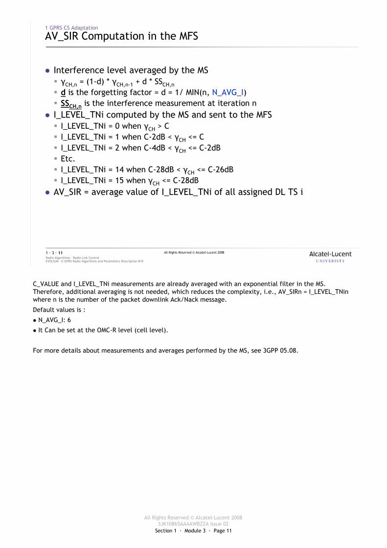
� Interference level averaged by the MS � γCH,n = (1-d) * γCH,n-1 + d * SSCH,n
� d is the forgetting factor = d = 1/ MIN(n, N_AVG_I)� SSCH,n is the interference measurement at iteration n
� I_LEVEL_TNi computed by the MS and sent to the MFS� I_LEVEL_TNi = 0 when γCH > C� I_LEVEL_TNi = 1 when C-2dB < γCH <= C� I_LEVEL_TNi = 2 when C-4dB < γCH <= C-2dB� Etc.� I_LEVEL_TNi = 14 when C-28dB < γCH <= C-26dB� I_LEVEL_TNi = 15 when γCH <= C-28dB
� AV_SIR = average value of I_LEVEL_TNi of all assigned DL TS i
C_VALUE and I_LEVEL_TNi measurements are already averaged with an exponential filter in the MS. Therefore, additional averaging is not needed, which reduces the complexity, i.e., AV_SIRn = I_LEVEL_TNin where n is the number of the packet downlink Ack/Nack message.
Default values is :
� N_AVG_I: 6
� It Can be set at the OMC-R level (cell level).
For more details about measurements and averages performed by the MS, see 3GPP 05.08.
Section 1 · Module 3 · Page 12
All Rights Reserved © Alcatel-Lucent 20083JK10865AAAAWBZZA Issue 02
All Rights Reserved © Alcatel-Lucent 2008
EVOLIUM · E-GPRS Radio Algorithms and Parameters Description B10Radio Algorithms · Radio Link Control1 · 3 · 12
1 GPRS CS Adaptation
DL CS Adaptation
O&M thresholdand hysteresis
new CS
current CS
- AV_RXQUAL_ST- AV_RXQUAL_LT- AV_SIR
MS MFS
(RXQUAL, I_Level_TNi)
Packet DL Ack/Nack
(RXQUAL, I_Level_TNi)
Packet DL Ack/Nack
Averaging
Linkadaptation
� Functional process
Section 1 · Module 3 · Page 13
All Rights Reserved © Alcatel-Lucent 20083JK10865AAAAWBZZA Issue 02
All Rights Reserved © Alcatel-Lucent 2008
EVOLIUM · E-GPRS Radio Algorithms and Parameters Description B10Radio Algorithms · Radio Link Control1 · 3 · 13
1 GPRS CS Adaptation
DL CS Adaptation [cont.]
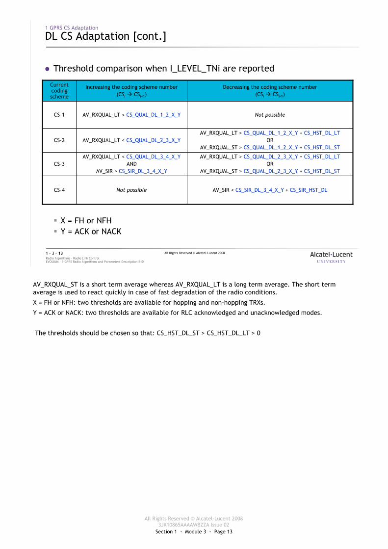
� Threshold comparison when I_LEVEL_TNi are reported
� X = FH or NFH� Y = ACK or NACK
AV_SIR < CS_SIR_DL_3_4_X_Y + CS_SIR_HST_DLNot possibleCS-4
AV_RXQUAL_LT > CS_QUAL_DL_2_3_X_Y + CS_HST_DL_LTOR
AV_RXQUAL_ST > CS_QUAL_DL_2_3_X_Y + CS_HST_DL_ST
AV_RXQUAL_LT < CS_QUAL_DL_3_4_X_YAND
AV_SIR > CS_SIR_DL_3_4_X_YCS-3
AV_RXQUAL_LT > CS_QUAL_DL_1_2_X_Y + CS_HST_DL_LTOR
AV_RXQUAL_ST > CS_QUAL_DL_1_2_X_Y + CS_HST_DL_STAV_RXQUAL_LT < CS_QUAL_DL_2_3_X_YCS-2
Not possibleAV_RXQUAL_LT < CS_QUAL_DL_1_2_X_YCS-1
Decreasing the coding scheme number(CSi � CSi-1)
Increasing the coding scheme number(CSi � CSi+1)
Current coding scheme
AV_RXQUAL_ST is a short term average whereas AV_RXQUAL_LT is a long term average. The short term average is used to react quickly in case of fast degradation of the radio conditions.
X = FH or NFH: two thresholds are available for hopping and non-hopping TRXs.
Y = ACK or NACK: two thresholds are available for RLC acknowledged and unacknowledged modes.
The thresholds should be chosen so that: CS_HST_DL_ST > CS_HST_DL_LT > 0
Section 1 · Module 3 · Page 14
All Rights Reserved © Alcatel-Lucent 20083JK10865AAAAWBZZA Issue 02
All Rights Reserved © Alcatel-Lucent 2008
EVOLIUM · E-GPRS Radio Algorithms and Parameters Description B10Radio Algorithms · Radio Link Control1 · 3 · 14
1 GPRS CS Adaptation
DL CS Adaptation [cont.]
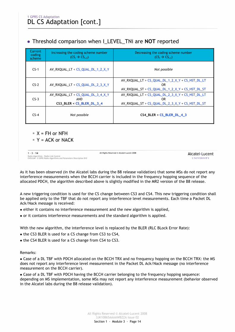
� Threshold comparison when I_LEVEL_TNi are NOT reported
� X = FH or NFH� Y = ACK or NACK
CS4_BLER > CS_BLER_DL_4_3Not possibleCS-4
AV_RXQUAL_LT > CS_QUAL_DL_2_3_X_Y + CS_HST_DL_LTOR
AV_RXQUAL_ST > CS_QUAL_DL_2_3_X_Y + CS_HST_DL_ST
AV_RXQUAL_LT < CS_QUAL_DL_3_4_X_YAND
CS3_BLER < CS_BLER_DL_3_4CS-3
AV_RXQUAL_LT > CS_QUAL_DL_1_2_X_Y + CS_HST_DL_LTOR
AV_RXQUAL_ST > CS_QUAL_DL_1_2_X_Y + CS_HST_DL_STAV_RXQUAL_LT < CS_QUAL_DL_2_3_X_YCS-2
Not possibleAV_RXQUAL_LT < CS_QUAL_DL_1_2_X_YCS-1
Decreasing the coding scheme number(CSi � CSi-1)
Increasing the coding scheme number(CSi � CSi+1)
Current coding scheme
As it has been observed (in the Alcatel labs during the B8 release validation) that some MSs do not report any interference measurements when the BCCH carrier is included in the frequency hopping sequence of the allocated PDCH, the algorithm described above is slightly modified in the MR2 version of the B8 release.
A new triggering condition is used for the CS change between CS3 and CS4. This new triggering condition shall be applied only to the TBF that do not report any interference level measurements. Each time a Packet DL Ack/Nack message is received:
� either it contains no interference measurement and the new algorithm is applied,
� or it contains interference measurements and the standard algorithm is applied.
With the new algorithm, the interference level is replaced by the BLER (RLC BLock Error Rate):
� the CS3 BLER is used for a CS change from CS3 to CS4,
� the CS4 BLER is used for a CS change from CS4 to CS3.
Remarks:
� Case of a DL TBF with PDCH allocated on the BCCH TRX and no frequency hopping on the BCCH TRX: the MS does not report any interference level measurement in the Packet DL Ack/Nack message (no interference measurement on the BCCH carrier).
� Case of a DL TBF with PDCH having the BCCH carrier belonging to the frequency hopping sequence: depending on MS implementation, some MSs may not report any interference measurement (behavior observed in the Alcatel labs during the B8 release validation).
Section 1 · Module 3 · Page 15
All Rights Reserved © Alcatel-Lucent 20083JK10865AAAAWBZZA Issue 02
All Rights Reserved © Alcatel-Lucent 2008
EVOLIUM · E-GPRS Radio Algorithms and Parameters Description B10Radio Algorithms · Radio Link Control1 · 3 · 15
1 GPRS CS Adaptation
DL CS Adaptation [cont.]
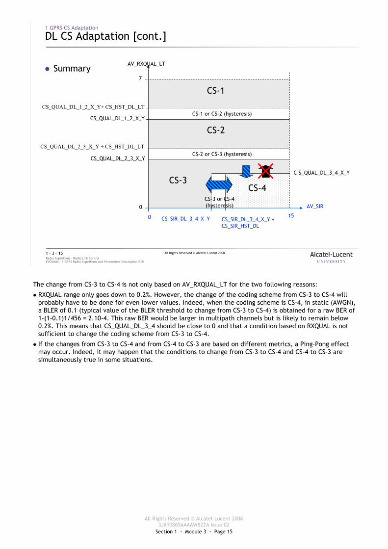
� SummaryAV_RXQUAL_LT
AV_SIR
CS-1
CS-2
CS-3CS-4
CS_QUAL_DL_1_2_X_Y+ CS_HST_DL_LT
CS_QUAL_DL_1_2_X_Y
CS_QUAL_DL_2_3_X_Y
C S_QUAL_DL_3_4_X_Y
0
7
0 15CS_SIR_DL_3_4_X_Y CS_SIR_DL_3_4_X_Y + CS_SIR_HST_DL
CS-1 or CS-2 (hysteresis)
CS-2 or CS-3 (hysteresis)
CS-3 or CS-4 (hysteresis)
CS_QUAL_DL_2_3_X_Y + CS_HST_DL_LT
BLER100% 0%CS_BLER_DL_3_4 CS_BLER_DL_4_3
The change from CS-3 to CS-4 is not only based on AV_RXQUAL_LT for the two following reasons:
� RXQUAL range only goes down to 0.2%. However, the change of the coding scheme from CS-3 to CS-4 will probably have to be done for even lower values. Indeed, when the coding scheme is CS-4, in static (AWGN), a BLER of 0.1 (typical value of the BLER threshold to change from CS-3 to CS-4) is obtained for a raw BER of 1-(1-0.1)1/456 = 2.10-4. This raw BER would be larger in multipath channels but is likely to remain below 0.2%. This means that CS_QUAL_DL_3_4 should be close to 0 and that a condition based on RXQUAL is not sufficient to change the coding scheme from CS-3 to CS-4.
� If the changes from CS-3 to CS-4 and from CS-4 to CS-3 are based on different metrics, a Ping-Pong effect may occur. Indeed, it may happen that the conditions to change from CS-3 to CS-4 and CS-4 to CS-3 are simultaneously true in some situations.
Section 1 · Module 3 · Page 16
All Rights Reserved © Alcatel-Lucent 20083JK10865AAAAWBZZA Issue 02
All Rights Reserved © Alcatel-Lucent 2008
EVOLIUM · E-GPRS Radio Algorithms and Parameters Description B10Radio Algorithms · Radio Link Control1 · 3 · 16
1 GPRS CS Adaptation
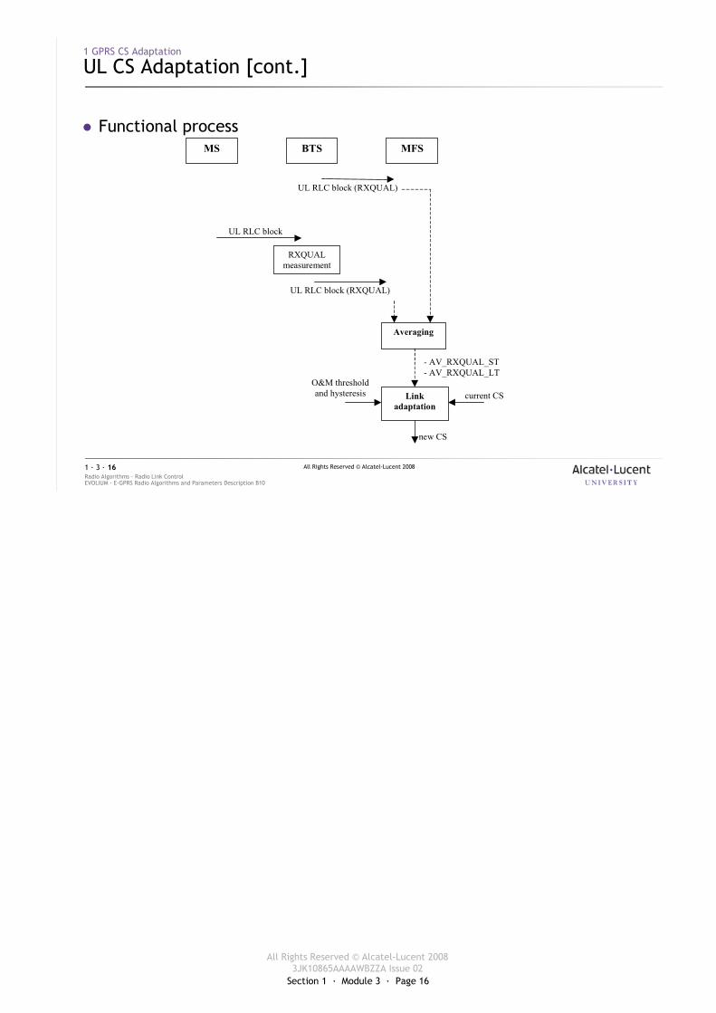
UL CS Adaptation [cont.]
� Functional process
O&M thresholdand hysteresis
new CS
current CS
- AV_RXQUAL_ST- AV_RXQUAL_LT
UL RLC block
Averaging
Linkadaptation
MS MFSBTS
RXQUALmeasurement
UL RLC block (RXQUAL)
UL RLC block (RXQUAL)
Section 1 · Module 3 · Page 17
All Rights Reserved © Alcatel-Lucent 20083JK10865AAAAWBZZA Issue 02
All Rights Reserved © Alcatel-Lucent 2008
EVOLIUM · E-GPRS Radio Algorithms and Parameters Description B10Radio Algorithms · Radio Link Control1 · 3 · 17
1 GPRS CS Adaptation
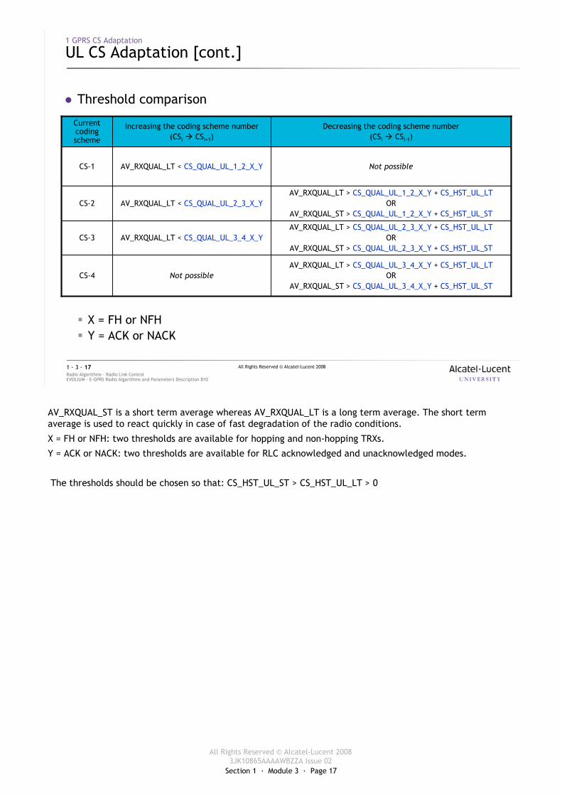
UL CS Adaptation [cont.]
� Threshold comparison
� X = FH or NFH� Y = ACK or NACK
AV_RXQUAL_LT > CS_QUAL_UL_3_4_X_Y + CS_HST_UL_LTOR
AV_RXQUAL_ST > CS_QUAL_UL_3_4_X_Y + CS_HST_UL_STNot possibleCS-4
AV_RXQUAL_LT > CS_QUAL_UL_2_3_X_Y + CS_HST_UL_LTOR
AV_RXQUAL_ST > CS_QUAL_UL_2_3_X_Y + CS_HST_UL_STAV_RXQUAL_LT < CS_QUAL_UL_3_4_X_YCS-3
AV_RXQUAL_LT > CS_QUAL_UL_1_2_X_Y + CS_HST_UL_LTOR
AV_RXQUAL_ST > CS_QUAL_UL_1_2_X_Y + CS_HST_UL_STAV_RXQUAL_LT < CS_QUAL_UL_2_3_X_YCS-2
Not possibleAV_RXQUAL_LT < CS_QUAL_UL_1_2_X_YCS-1
Decreasing the coding scheme number(CSi � CSi-1)
Increasing the coding scheme number(CSi � CSi+1)
Current coding scheme
AV_RXQUAL_ST is a short term average whereas AV_RXQUAL_LT is a long term average. The short term average is used to react quickly in case of fast degradation of the radio conditions.
X = FH or NFH: two thresholds are available for hopping and non-hopping TRXs.
Y = ACK or NACK: two thresholds are available for RLC acknowledged and unacknowledged modes.
The thresholds should be chosen so that: CS_HST_UL_ST > CS_HST_UL_LT > 0
Section 1 · Module 3 · Page 18
All Rights Reserved © Alcatel-Lucent 20083JK10865AAAAWBZZA Issue 02
All Rights Reserved © Alcatel-Lucent 2008
EVOLIUM · E-GPRS Radio Algorithms and Parameters Description B10Radio Algorithms · Radio Link Control1 · 3 · 18
1 GPRS CS Adaptation
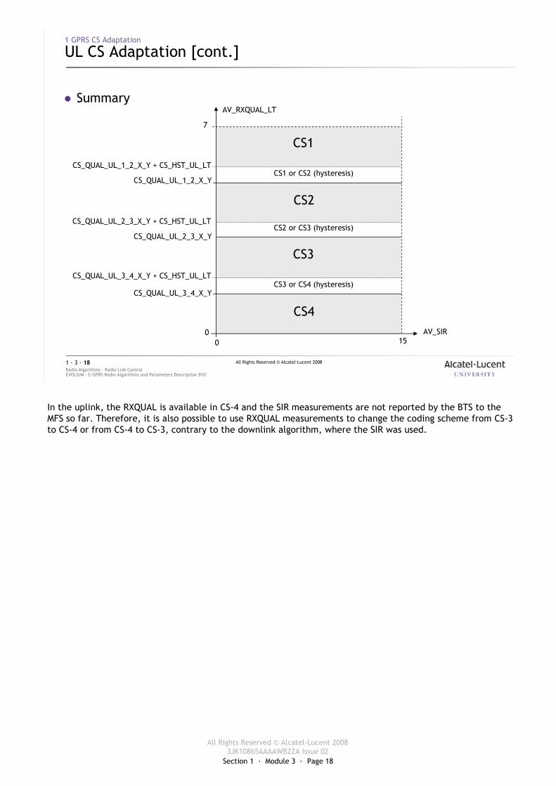
UL CS Adaptation [cont.]
� SummaryAV_RXQUAL_LT
AV_SIR
CS1
CS2
CS_QUAL_UL_1_2_X_Y + CS_HST_UL_LT
CS_QUAL_UL_1_2_X_Y
CS_QUAL_UL_2_3_X_Y
0
7
0 15
CS1 or CS2 (hysteresis)
CS2 or CS3 (hysteresis)
CS3
CS4
CS3 or CS4 (hysteresis)CS_QUAL_UL_3_4_X_Y
CS_QUAL_UL_2_3_X_Y + CS_HST_UL_LT
CS_QUAL_UL_3_4_X_Y + CS_HST_UL_LT
In the uplink, the RXQUAL is available in CS-4 and the SIR measurements are not reported by the BTS to the MFS so far. Therefore, it is also possible to use RXQUAL measurements to change the coding scheme from CS-3 to CS-4 or from CS-4 to CS-3, contrary to the downlink algorithm, where the SIR was used.
Section 1 · Module 3 · Page 19
All Rights Reserved © Alcatel-Lucent 20083JK10865AAAAWBZZA Issue 02
All Rights Reserved © Alcatel-Lucent 2008
EVOLIUM · E-GPRS Radio Algorithms and Parameters Description B10Radio Algorithms · Radio Link Control1 · 3 · 19
1 GPRS CS Adaptation
Execution
� UL TBF:� the CS to be used is indicated to the MS during the establishment phase� if a CS adaptation is decided by the MFS during the transfer phase, a PACKET
UL ACK/NACK message is sent immediately to the MS
� DL TBF:� if a CS adaptation is decided by the MFS during the transfer phase, the MFS
modifies the CS
Section 1 · Module 3 · Page 20
All Rights Reserved © Alcatel-Lucent 20083JK10865AAAAWBZZA Issue 02
All Rights Reserved © Alcatel-Lucent 2008
EVOLIUM · E-GPRS Radio Algorithms and Parameters Description B10Radio Algorithms · Radio Link Control1 · 3 · 20
1 GPRS CS Adaptation
Defense Procedure
� In a DL TBF:If the number of PACKET DL ACK/NACK messages consecutively lost from the MS on the radio interface goes over TBF_CS_DL, the coding scheme is changed to CS-1
� In a UL TBF:If the number of radio blocks consecutively not decoded goes over the threshold Nb_allocated_TS x TBF_CS_UL, the coding scheme is changed to CS-1
� In both cases, the CS must not be changed again before TBF_CS_PERIOD RLC blocks are transmitted
B10
TBF_CS_DL = 8 (Alcatel recommended value) and it can be set at OMC-R level.
TBF_CS_UL = 32 (Alcatel recommended value) and it can be set at OMC-R level.
TBF_CS_PERIOD = 20 (Alcatel recommended value) and it cannot be set at OMC-R level.
Section 1 · Module 3 · Page 21
All Rights Reserved © Alcatel-Lucent 20083JK10865AAAAWBZZA Issue 02
All Rights Reserved © Alcatel-Lucent 2008
EVOLIUM · E-GPRS Radio Algorithms and Parameters Description B10Radio Algorithms · Radio Link Control1 · 3 · 21
1 GPRS CS Adaptation
Initial Coding Scheme
� The initial CS at TBF establishment is given by the cell parameters:� TBF_DL_INIT_CS for a DL TBF & TBF_UL_INIT_CS for a UL TBF� Range = CS-1, CS-2, CS-3, CS-4� Default value = CS-2
� T_DL_GPRS_MeasReport: the time period to request for a “Packet Downlink Ack/Nack” with measurements� Range: from 60 to 3000 ms� Default value = 400 ms
� The initial CS and CS changes are limited by the cell parameter MAX_GPRS_CS
� Range = CS-2, CS-3, CS-4 � Default value = CS-2
Exercise
Rules:
� TBF_DL_INIT_CS < MAX_GPRS_CS
� TBF_UL_INIT_CS < MAX_GPRS_CS
When a new LLC PDU is received and the downlink transfer is resumed, the timer defined by CS_MAX_IDLE_PERIOD shall be checked. If it has not expired, then the coding scheme or modulation and coding scheme of the previous DL TBF shall be re-used.

Section 1 · Module 3 · Page 22
All Rights Reserved © Alcatel-Lucent 20083JK10865AAAAWBZZA Issue 02
All Rights Reserved © Alcatel-Lucent 2008
EVOLIUM · E-GPRS Radio Algorithms and Parameters Description B10Radio Algorithms · Radio Link Control1 · 3 · 22
2 EGPRS MCS Adaptation
Section 1 · Module 3 · Page 23
All Rights Reserved © Alcatel-Lucent 20083JK10865AAAAWBZZA Issue 02
All Rights Reserved © Alcatel-Lucent 2008
EVOLIUM · E-GPRS Radio Algorithms and Parameters Description B10Radio Algorithms · Radio Link Control1 · 3 · 23
2 EGPRS MCS Adaptation
Impact of the Output Power – DL Case
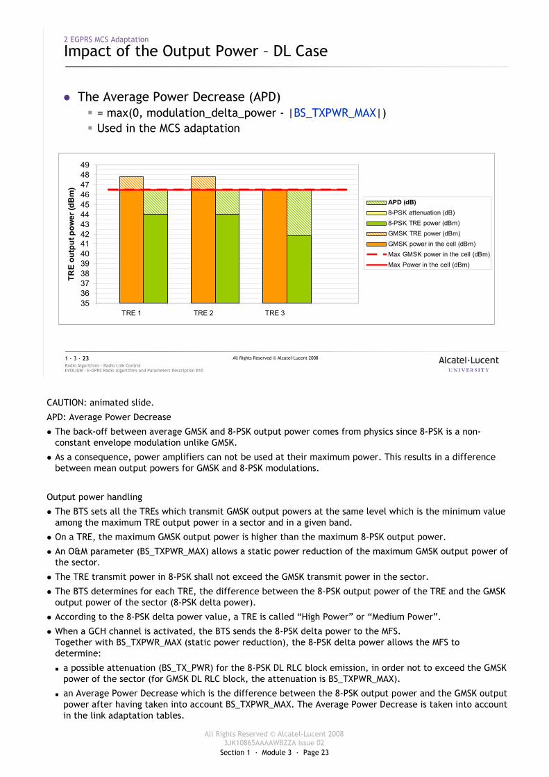
� The Average Power Decrease (APD)� = max(0, modulation_delta_power - |BS_TXPWR_MAX|)� Used in the MCS adaptation
TRE 1 TRE 2 TRE 3
353637383940414243444546474849
TRE 1 TRE 2 TRE 3
TRE
outp
utpo
wer
(dB
m)
APD (dB)8-PSK attenuation (dB)8-PSK TRE power (dBm)GMSK TRE power (dBm)GMSK power in the cell (dBm)Max GMSK power in the cell (dBm)Max Power in the cell (dBm)
CAUTION: animated slide.
APD: Average Power Decrease
� The back-off between average GMSK and 8-PSK output power comes from physics since 8-PSK is a non-constant envelope modulation unlike GMSK.
� As a consequence, power amplifiers can not be used at their maximum power. This results in a difference between mean output powers for GMSK and 8-PSK modulations.
Output power handling
� The BTS sets all the TREs which transmit GMSK output powers at the same level which is the minimum value among the maximum TRE output power in a sector and in a given band.
� On a TRE, the maximum GMSK output power is higher than the maximum 8-PSK output power.
� An O&M parameter (BS_TXPWR_MAX) allows a static power reduction of the maximum GMSK output power of the sector.
� The TRE transmit power in 8-PSK shall not exceed the GMSK transmit power in the sector.
� The BTS determines for each TRE, the difference between the 8-PSK output power of the TRE and the GMSK output power of the sector (8-PSK delta power).
� According to the 8-PSK delta power value, a TRE is called “High Power” or “Medium Power”.
� When a GCH channel is activated, the BTS sends the 8-PSK delta power to the MFS.Together with BS_TXPWR_MAX (static power reduction), the 8-PSK delta power allows the MFS to determine:
� a possible attenuation (BS_TX_PWR) for the 8-PSK DL RLC block emission, in order not to exceed the GMSK power of the sector (for GMSK DL RLC block, the attenuation is BS_TXPWR_MAX).
� an Average Power Decrease which is the difference between the 8-PSK output power and the GMSK output power after having taken into account BS_TXPWR_MAX. The Average Power Decrease is taken into account in the link adaptation tables.
Section 1 · Module 3 · Page 24
All Rights Reserved © Alcatel-Lucent 20083JK10865AAAAWBZZA Issue 02
All Rights Reserved © Alcatel-Lucent 2008
EVOLIUM · E-GPRS Radio Algorithms and Parameters Description B10Radio Algorithms · Radio Link Control1 · 3 · 24
2 EGPRS MCS Adaptation
Impact of the Output Power – UL Case
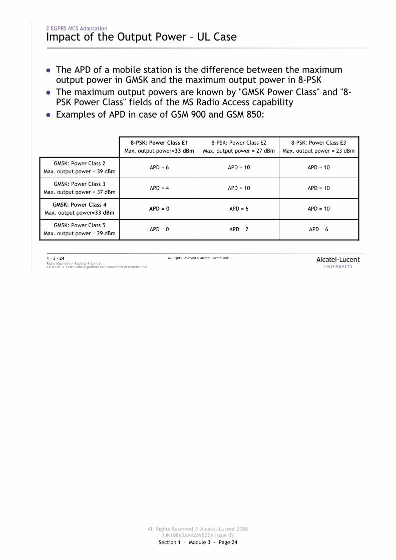
� The APD of a mobile station is the difference between the maximum output power in GMSK and the maximum output power in 8-PSK
� The maximum output powers are known by "GMSK Power Class" and "8-PSK Power Class" fields of the MS Radio Access capability
� Examples of APD in case of GSM 900 and GSM 850:
APD = 6APD = 2APD = 0GMSK: Power Class 5
Max. output power = 29 dBm
APD = 10APD = 6APD = 0GMSK: Power Class 4
Max. output power=33 dBm
APD = 10APD = 10APD = 4GMSK: Power Class 3
Max. output power = 37 dBm
APD = 10APD = 10APD = 6GMSK: Power Class 2
Max. output power = 39 dBm
8-PSK: Power Class E3Max. output power = 23 dBm
8-PSK: Power Class E2Max. output power = 27 dBm
8-PSK: Power Class E1Max. output power=33 dBm
Section 1 · Module 3 · Page 25
All Rights Reserved © Alcatel-Lucent 20083JK10865AAAAWBZZA Issue 02
All Rights Reserved © Alcatel-Lucent 2008
EVOLIUM · E-GPRS Radio Algorithms and Parameters Description B10Radio Algorithms · Radio Link Control1 · 3 · 25
2 EGPRS MCS Adaptation
Measurement Reporting
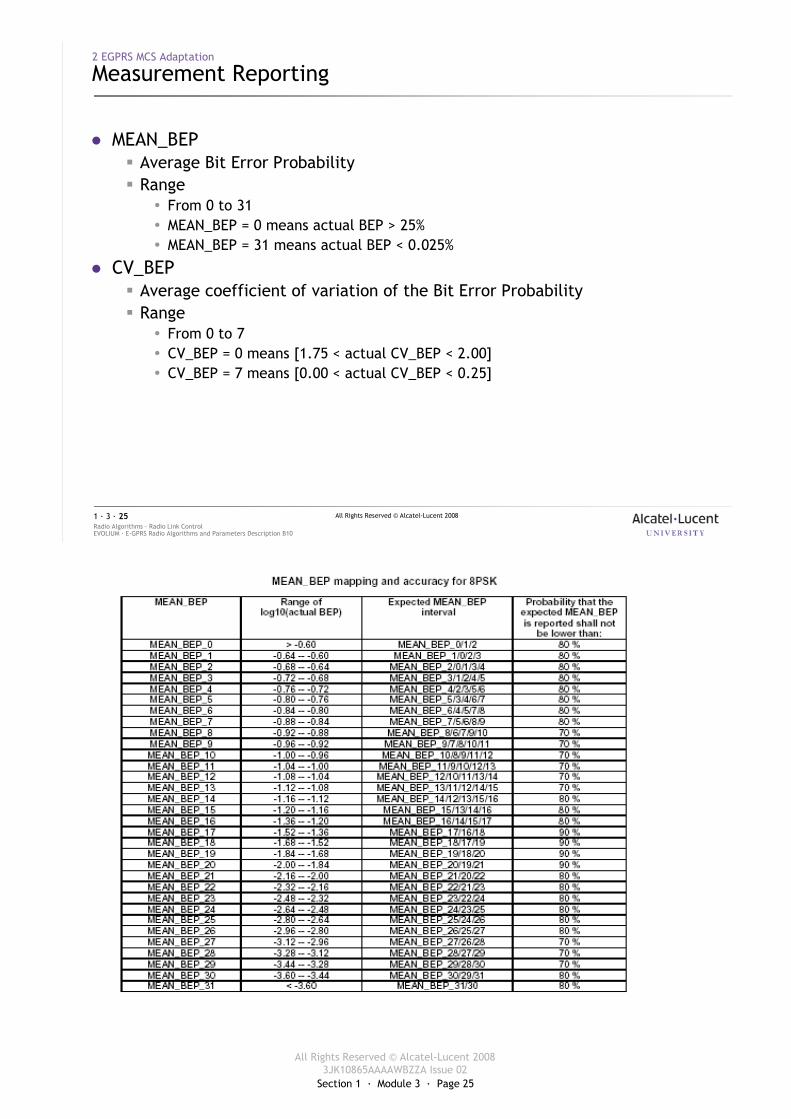
� MEAN_BEP� Average Bit Error Probability� Range
� From 0 to 31� MEAN_BEP = 0 means actual BEP > 25%� MEAN_BEP = 31 means actual BEP < 0.025%
� CV_BEP� Average coefficient of variation of the Bit Error Probability� Range
� From 0 to 7� CV_BEP = 0 means [1.75 < actual CV_BEP < 2.00]� CV_BEP = 7 means [0.00 < actual CV_BEP < 0.25]
Section 1 · Module 3 · Page 26
All Rights Reserved © Alcatel-Lucent 20083JK10865AAAAWBZZA Issue 02
All Rights Reserved © Alcatel-Lucent 2008
EVOLIUM · E-GPRS Radio Algorithms and Parameters Description B10Radio Algorithms · Radio Link Control1 · 3 · 26
2 EGPRS MCS Adaptation
Measurement Reporting [cont.]
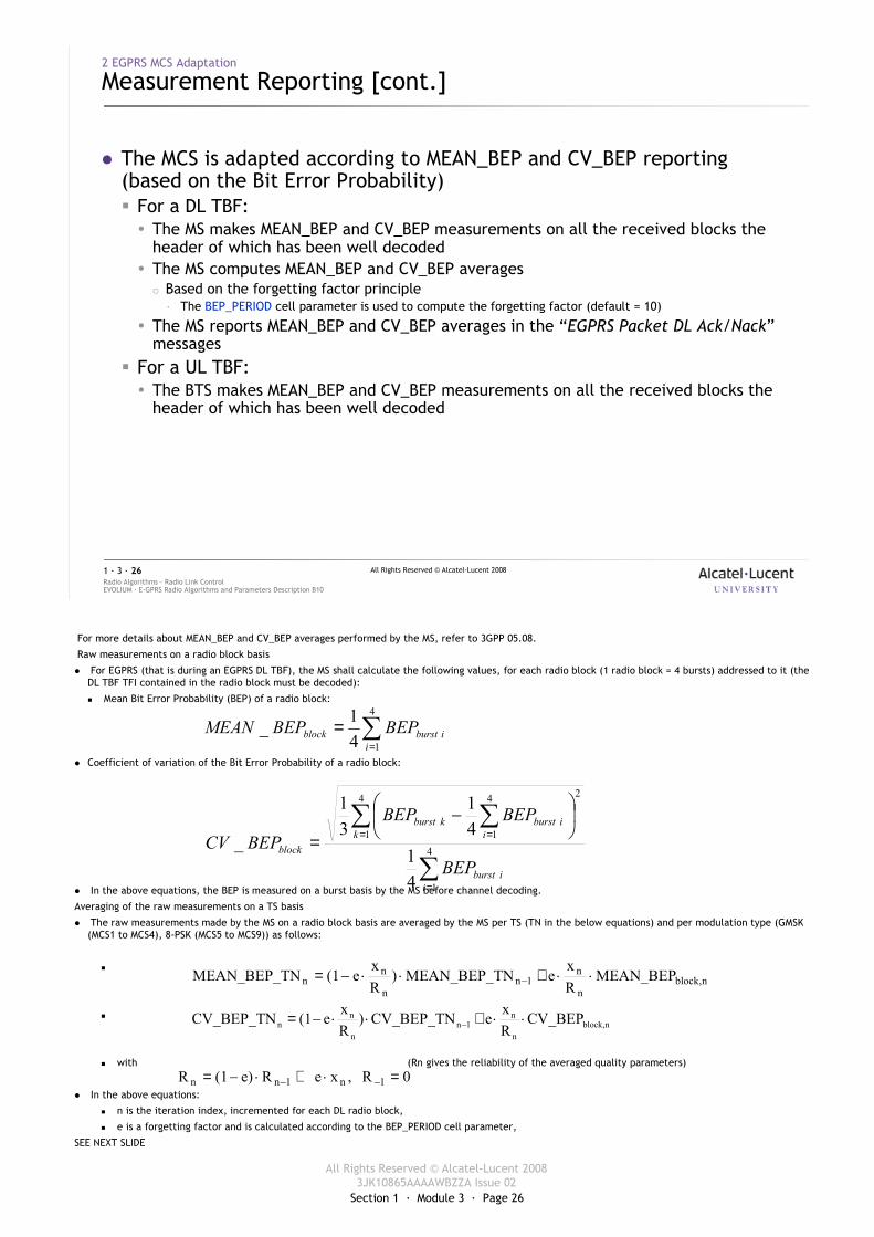
� The MCS is adapted according to MEAN_BEP and CV_BEP reporting (based on the Bit Error Probability)� For a DL TBF:� The MS makes MEAN_BEP and CV_BEP measurements on all the received blocks the
header of which has been well decoded� The MS computes MEAN_BEP and CV_BEP averages
� Based on the forgetting factor principle· The BEP_PERIOD cell parameter is used to compute the forgetting factor (default = 10)
� The MS reports MEAN_BEP and CV_BEP averages in the “EGPRS Packet DL Ack/Nack”messages
� For a UL TBF:� The BTS makes MEAN_BEP and CV_BEP measurements on all the received blocks the
header of which has been well decoded
For more details about MEAN_BEP and CV_BEP averages performed by the MS, refer to 3GPP 05.08.
Raw measurements on a radio block basis
� For EGPRS (that is during an EGPRS DL TBF), the MS shall calculate the following values, for each radio block (1 radio block = 4 bursts) addressed to it (the DL TBF TFI contained in the radio block must be decoded):
� Mean Bit Error Probability (BEP) of a radio block:
� Coefficient of variation of the Bit Error Probability of a radio block:
� In the above equations, the BEP is measured on a burst basis by the MS before channel decoding.
Averaging of the raw measurements on a TS basis
� The raw measurements made by the MS on a radio block basis are averaged by the MS per TS (TN in the below equations) and per modulation type (GMSK (MCS1 to MCS4), 8-PSK (MCS5 to MCS9)) as follows:
�
�
� with (Rn gives the reliability of the averaged quality parameters)
� In the above equations:
� n is the iteration index, incremented for each DL radio block,
� e is a forgetting factor and is calculated according to the BEP_PERIOD cell parameter,
SEE NEXT SLIDE
∑=
=4
141_i
iburstblock BEPBEPMEAN
∑
∑ ∑
=
= =
−
= 4
1
24
1
4
1
41
41
31
_
iiburst
k iiburstkburst
block
BEP
BEPBEPBEPCV
nblock,n
n1n
n
nn MEAN_BEP
Rx
eNMEAN_BEP_T)Rx
e(1NMEAN_BEP_T ⋅⋅+⋅⋅−= −
nblock,n
n1n
n
nn CV_BEP
RxeCV_BEP_TN)
Rxe(1CV_BEP_TN ⋅⋅+⋅⋅−= −
0R,xeRe)(1R 1n1nn =⋅+⋅−= −−
Section 1 · Module 3 · Page 27
All Rights Reserved © Alcatel-Lucent 20083JK10865AAAAWBZZA Issue 02
All Rights Reserved © Alcatel-Lucent 2008
EVOLIUM · E-GPRS Radio Algorithms and Parameters Description B10Radio Algorithms · Radio Link Control1 · 3 · 27
2 EGPRS MCS Adaptation
DL MCS Adaptation
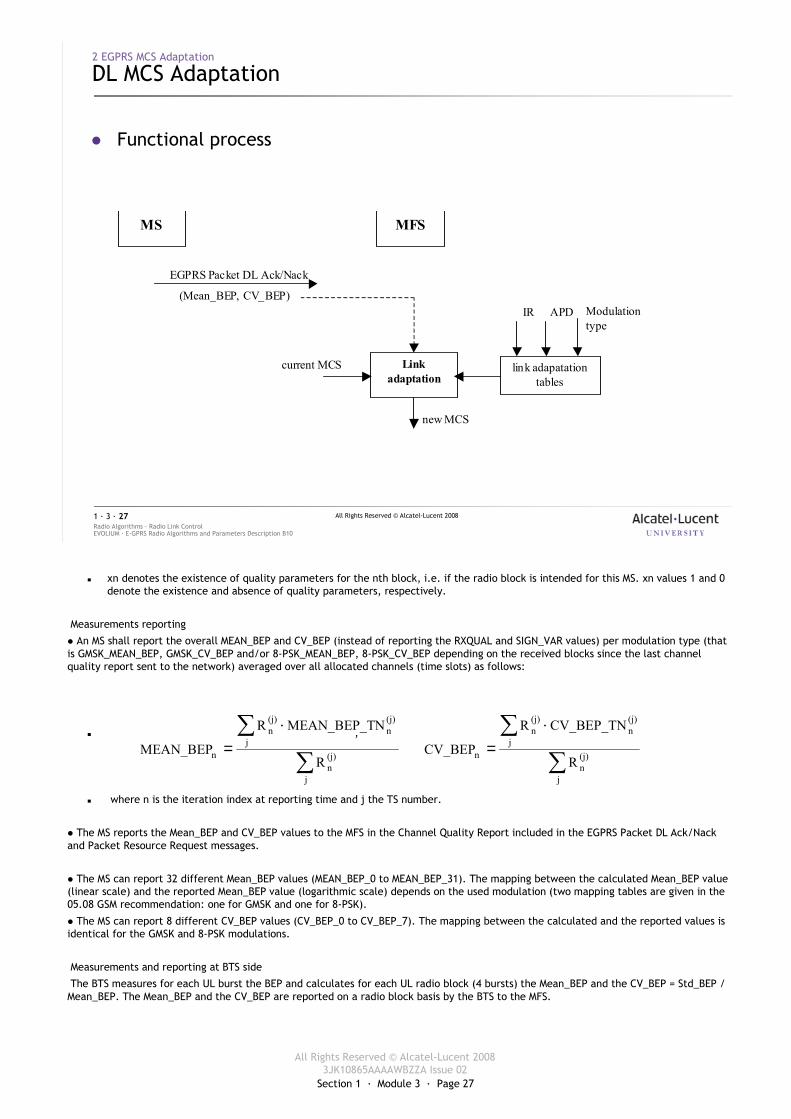
� Functional process
APD IR
link adapatationtables
new MCS
current MCS
MS MFS
(Mean_BEP, CV_BEP)
EGPRS Packet DL Ack/Nack
Link adaptation
Modulation type
� xn denotes the existence of quality parameters for the nth block, i.e. if the radio block is intended for this MS. xn values 1 and 0 denote the existence and absence of quality parameters, respectively.
Measurements reporting
� An MS shall report the overall MEAN_BEP and CV_BEP (instead of reporting the RXQUAL and SIGN_VAR values) per modulation type (that is GMSK_MEAN_BEP, GMSK_CV_BEP and/or 8-PSK_MEAN_BEP, 8-PSK_CV_BEP depending on the received blocks since the last channel quality report sent to the network) averaged over all allocated channels (time slots) as follows:
� ,
� where n is the iteration index at reporting time and j the TS number.
� The MS reports the Mean_BEP and CV_BEP values to the MFS in the Channel Quality Report included in the EGPRS Packet DL Ack/Nackand Packet Resource Request messages.
� The MS can report 32 different Mean_BEP values (MEAN_BEP_0 to MEAN_BEP_31). The mapping between the calculated Mean_BEP value (linear scale) and the reported Mean_BEP value (logarithmic scale) depends on the used modulation (two mapping tables are given in the 05.08 GSM recommendation: one for GMSK and one for 8-PSK).
� The MS can report 8 different CV_BEP values (CV_BEP_0 to CV_BEP_7). The mapping between the calculated and the reported values is identical for the GMSK and 8-PSK modulations.
Measurements and reporting at BTS side
The BTS measures for each UL burst the BEP and calculates for each UL radio block (4 bursts) the Mean_BEP and the CV_BEP = Std_BEP / Mean_BEP. The Mean_BEP and the CV_BEP are reported on a radio block basis by the BTS to the MFS.
∑∑ ⋅
=
j
(j)n
j
(j)n
(j)n
n R
NMEAN_BEP_TR
MEAN_BEP∑
∑ ⋅=
j
(j)n
j
(j)n
(j)n
n R
CV_BEP_TNR
CV_BEP
Section 1 · Module 3 · Page 28
All Rights Reserved © Alcatel-Lucent 20083JK10865AAAAWBZZA Issue 02
All Rights Reserved © Alcatel-Lucent 2008
EVOLIUM · E-GPRS Radio Algorithms and Parameters Description B10Radio Algorithms · Radio Link Control1 · 3 · 28
2 EGPRS MCS Adaptation
DL MCS Adaptation [cont.]
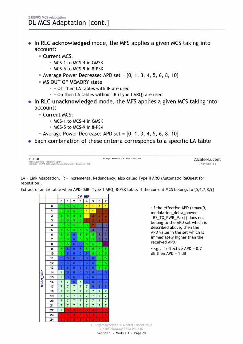
� In RLC acknowledged mode, the MFS applies a given MCS taking into account:� Current MCS:
� MCS-1 to MCS-4 in GMSK � MCS-5 to MCS-9 in 8-PSK
� Average Power Decrease: APD set = [0, 1, 3, 4, 5, 6, 8, 10]� MS OUT OF MEMORY state
� = Off then LA tables with IR are used� = On then LA tables without IR (Type I ARQ) are used
� In RLC unacknowledged mode, the MFS applies a given MCS taking into account:� Current MCS:
� MCS-1 to MCS-4 in GMSK � MCS-5 to MCS-9 In 8-PSK
� Average Power Decrease: APD set = [0, 1, 3, 4, 5, 6, 8, 10]� Each combination of these criteria corresponds to a specific LA table
LA = Link Adaptation. IR = Incremental Redundancy, also called Type II ARQ (Automatic ReQuest for repetition).
Extract of an LA table when APD=0dB, Type 1 ARQ, 8-PSK table: if the current MCS belongs to {5,6,7,8,9}
0 1 2 3 4 5 6 70 5 5 5 5 1 1 1 11 5 5 5 5 1 1 2 22 5 5 5 5 1 2 2 23 5 5 5 5 2 2 2 34 5 5 5 5 5 2 3 35 5 5 5 5 5 3 3 36 5 5 6 5 5 5 3 37 5 5 6 5 5 5 3 38 5 5 6 6 5 5 5 49 5 6 6 6 5 5 5 5
10 5 6 6 6 6 5 5 511 6 6 6 6 6 6 5 512 6 6 6 6 6 6 5 513 6 6 6 6 6 6 5 514 7 6 6 6 6 6 6 615 7 6 6 6 6 6 6 616 7 7 6 7 6 6 6 617 7 7 7 7 7 6 6 618 7 7 7 7 7 7 7 719 7 7 7 7 7 7 7 720 7 7 7 7 7 7 7 721 7 7 7 7 7 7 7 722 7 8 8 8 8 8 8 823 8 8 8 8 8 8 8 824 8 8 8 8 8 8 8 8
CV_BEP
MEA
N_B
EP
·If the effective APD (=max(0, modulation_delta_power -|BS_TX_PWR_Max|) does not belong to the APD set which is described above, then the APD value in the set which is immediately higher than the received APD.
·e.g., if effective APD = 0.7 dB then APD = 1 dB
Section 1 · Module 3 · Page 29
All Rights Reserved © Alcatel-Lucent 20083JK10865AAAAWBZZA Issue 02
All Rights Reserved © Alcatel-Lucent 2008
EVOLIUM · E-GPRS Radio Algorithms and Parameters Description B10Radio Algorithms · Radio Link Control1 · 3 · 29
2 EGPRS MCS Adaptation
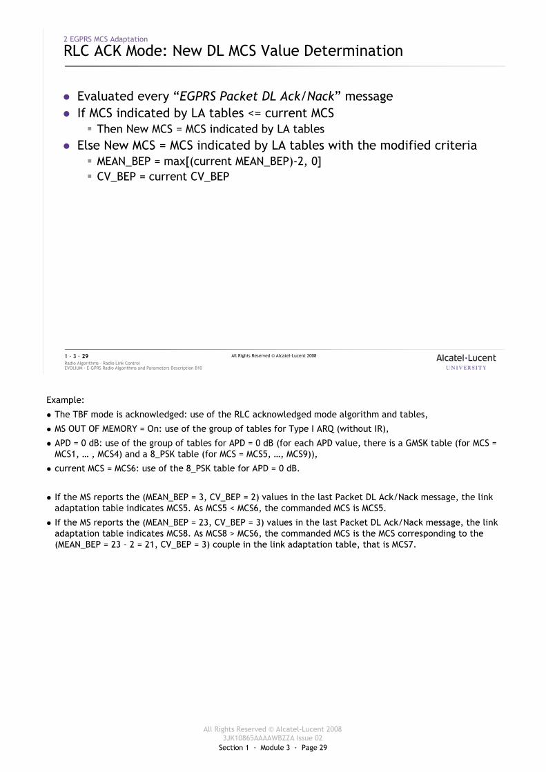
RLC ACK Mode: New DL MCS Value Determination
� Evaluated every “EGPRS Packet DL Ack/Nack” message� If MCS indicated by LA tables <= current MCS
� Then New MCS = MCS indicated by LA tables� Else New MCS = MCS indicated by LA tables with the modified criteria
� MEAN_BEP = max[(current MEAN_BEP)-2, 0]� CV_BEP = current CV_BEP
Example:
� The TBF mode is acknowledged: use of the RLC acknowledged mode algorithm and tables,
� MS OUT OF MEMORY = On: use of the group of tables for Type I ARQ (without IR),
� APD = 0 dB: use of the group of tables for APD = 0 dB (for each APD value, there is a GMSK table (for MCS = MCS1, … , MCS4) and a 8_PSK table (for MCS = MCS5, …, MCS9)),
� current MCS = MCS6: use of the 8_PSK table for APD = 0 dB.
� If the MS reports the (MEAN_BEP = 3, CV_BEP = 2) values in the last Packet DL Ack/Nack message, the link adaptation table indicates MCS5. As MCS5 < MCS6, the commanded MCS is MCS5.
� If the MS reports the (MEAN_BEP = 23, CV_BEP = 3) values in the last Packet DL Ack/Nack message, the link adaptation table indicates MCS8. As MCS8 > MCS6, the commanded MCS is the MCS corresponding to the (MEAN_BEP = 23 – 2 = 21, CV_BEP = 3) couple in the link adaptation table, that is MCS7.
Section 1 · Module 3 · Page 30
All Rights Reserved © Alcatel-Lucent 20083JK10865AAAAWBZZA Issue 02
All Rights Reserved © Alcatel-Lucent 2008
EVOLIUM · E-GPRS Radio Algorithms and Parameters Description B10Radio Algorithms · Radio Link Control1 · 3 · 30
2 EGPRS MCS Adaptation
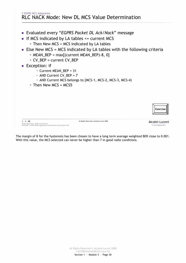
RLC NACK Mode: New DL MCS Value Determination
� Evaluated every “EGPRS Packet DL Ack/Nack” message� If MCS indicated by LA tables <= current MCS
� Then New MCS = MCS indicated by LA tables� Else New MCS = MCS indicated by LA tables with the following criteria
� MEAN_BEP = max[(current MEAN_BEP)-8, 0]� CV_BEP = current CV_BEP
� Exception: if � Current MEAN_BEP = 31� AND Current CV_BEP = 7� AND Current MCS belongs to {MCS-1, MCS-2, MCS-3, MCS-4)
� Then New MCS = MCS5
Exercise
The margin of 8 for the hysteresis has been chosen to have a long term average weighted BER close to 0.001. With this value, the MCS selected can never be higher than 7 in good radio conditions.
Section 1 · Module 3 · Page 31
All Rights Reserved © Alcatel-Lucent 20083JK10865AAAAWBZZA Issue 02
All Rights Reserved © Alcatel-Lucent 2008
EVOLIUM · E-GPRS Radio Algorithms and Parameters Description B10Radio Algorithms · Radio Link Control1 · 3 · 31
2 EGPRS MCS Adaptation
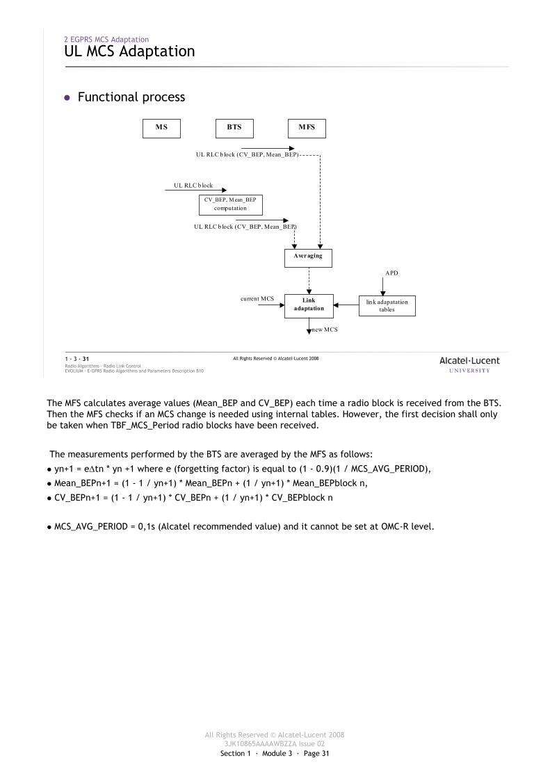
UL MCS Adaptation
� Functional process
UL RLC b lock (CV_ BEP, Mean_BEP)
new MCS
current MCS
UL RLC b lock
Averaging
Link adaptation
MS MFS BTS
CV_BEP, M ean_BEPcomputation
UL RLC b lock (CV_ BEP, Mean_BEP)
lin k adapatationtables
APD
The MFS calculates average values (Mean_BEP and CV_BEP) each time a radio block is received from the BTS. Then the MFS checks if an MCS change is needed using internal tables. However, the first decision shall only be taken when TBF_MCS_Period radio blocks have been received.
The measurements performed by the BTS are averaged by the MFS as follows:
� yn+1 = e∆tn * yn +1 where e (forgetting factor) is equal to (1 - 0.9)(1 / MCS_AVG_PERIOD),
� Mean_BEPn+1 = (1 - 1 / yn+1) * Mean_BEPn + (1 / yn+1) * Mean_BEPblock n,
� CV_BEPn+1 = (1 - 1 / yn+1) * CV_BEPn + (1 / yn+1) * CV_BEPblock n
� MCS_AVG_PERIOD = 0,1s (Alcatel recommended value) and it cannot be set at OMC-R level.
Section 1 · Module 3 · Page 32
All Rights Reserved © Alcatel-Lucent 20083JK10865AAAAWBZZA Issue 02
All Rights Reserved © Alcatel-Lucent 2008
EVOLIUM · E-GPRS Radio Algorithms and Parameters Description B10Radio Algorithms · Radio Link Control1 · 3 · 32
2 EGPRS MCS Adaptation
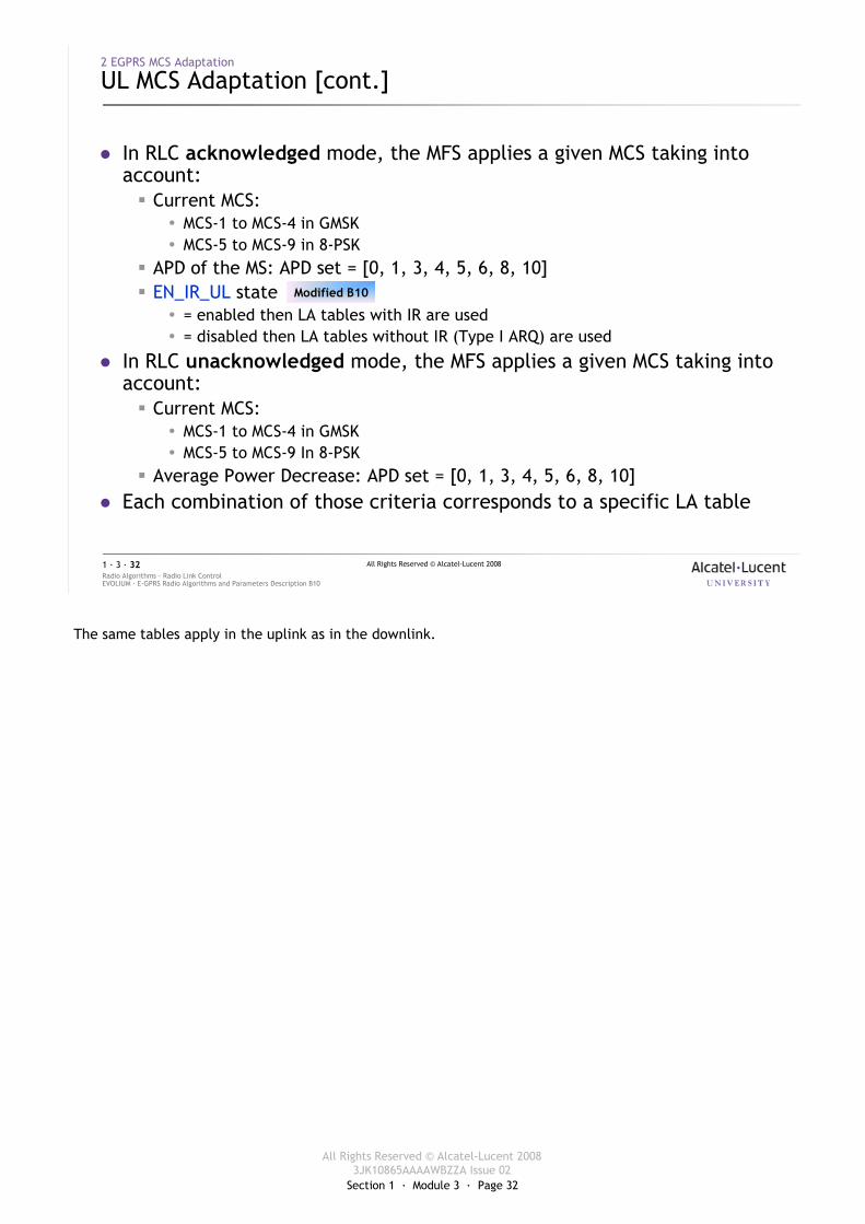
UL MCS Adaptation [cont.]
� In RLC acknowledged mode, the MFS applies a given MCS taking into account:� Current MCS:
� MCS-1 to MCS-4 in GMSK � MCS-5 to MCS-9 in 8-PSK
� APD of the MS: APD set = [0, 1, 3, 4, 5, 6, 8, 10]� EN_IR_UL state
� = enabled then LA tables with IR are used� = disabled then LA tables without IR (Type I ARQ) are used
� In RLC unacknowledged mode, the MFS applies a given MCS taking into account:� Current MCS:
� MCS-1 to MCS-4 in GMSK � MCS-5 to MCS-9 In 8-PSK
� Average Power Decrease: APD set = [0, 1, 3, 4, 5, 6, 8, 10]� Each combination of those criteria corresponds to a specific LA table
Modified B10
The same tables apply in the uplink as in the downlink.
Section 1 · Module 3 · Page 33
All Rights Reserved © Alcatel-Lucent 20083JK10865AAAAWBZZA Issue 02
All Rights Reserved © Alcatel-Lucent 2008
EVOLIUM · E-GPRS Radio Algorithms and Parameters Description B10Radio Algorithms · Radio Link Control1 · 3 · 33
2 EGPRS MCS Adaptation
RLC ACK Mode: New UL MCS Value Determination
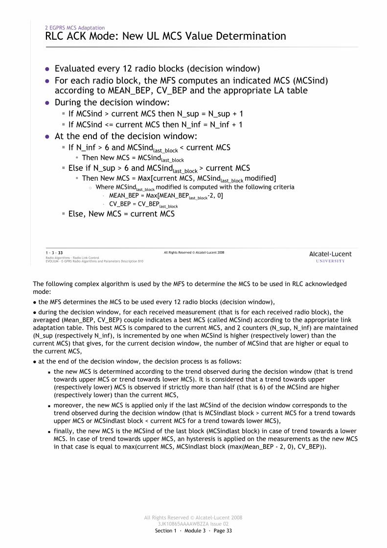
� Evaluated every 12 radio blocks (decision window)� For each radio block, the MFS computes an indicated MCS (MCSind)
according to MEAN_BEP, CV_BEP and the appropriate LA table� During the decision window:
� If MCSind > current MCS then N_sup = N_sup + 1� If MCSind <= current MCS then N_inf = N_inf + 1
� At the end of the decision window:� If N_inf > 6 and MCSindlast_block < current MCS
� Then New MCS = MCSindlast_block
� Else if N_sup > 6 and MCSindlast_block > current MCS� Then New MCS = Max[current MCS, MCSindlast_block modified]
� Where MCSindlast_block modified is computed with the following criteria· MEAN_BEP = Max[MEAN_BEPlast_block-2, 0]· CV_BEP = CV_BEPlast_block
� Else, New MCS = current MCS
The following complex algorithm is used by the MFS to determine the MCS to be used in RLC acknowledged mode:
� the MFS determines the MCS to be used every 12 radio blocks (decision window),
� during the decision window, for each received measurement (that is for each received radio block), the averaged (Mean_BEP, CV_BEP) couple indicates a best MCS (called MCSind) according to the appropriate link adaptation table. This best MCS is compared to the current MCS, and 2 counters (N_sup, N_inf) are maintained (N_sup (respectively N_inf), is incremented by one when MCSind is higher (respectively lower) than the current MCS) that gives, for the current decision window, the number of MCSind that are higher or equal to the current MCS,
� at the end of the decision window, the decision process is as follows:
� the new MCS is determined according to the trend observed during the decision window (that is trend towards upper MCS or trend towards lower MCS). It is considered that a trend towards upper (respectively lower) MCS is observed if strictly more than half (that is 6) of the MCSind are higher (respectively lower) than the current MCS,
� moreover, the new MCS is applied only if the last MCSind of the decision window corresponds to the trend observed during the decision window (that is MCSindlast block > current MCS for a trend towards upper MCS or MCSindlast block < current MCS for a trend towards lower MCS),
� finally, the new MCS is the MCSind of the last block (MCSindlast block) in case of trend towards a lower MCS. In case of trend towards upper MCS, an hysteresis is applied on the measurements as the new MCS in that case is equal to max(current MCS, MCSindlast block (max(Mean_BEP - 2, 0), CV_BEP)).
Section 1 · Module 3 · Page 34
All Rights Reserved © Alcatel-Lucent 20083JK10865AAAAWBZZA Issue 02
All Rights Reserved © Alcatel-Lucent 2008
EVOLIUM · E-GPRS Radio Algorithms and Parameters Description B10Radio Algorithms · Radio Link Control1 · 3 · 34
2 EGPRS MCS Adaptation
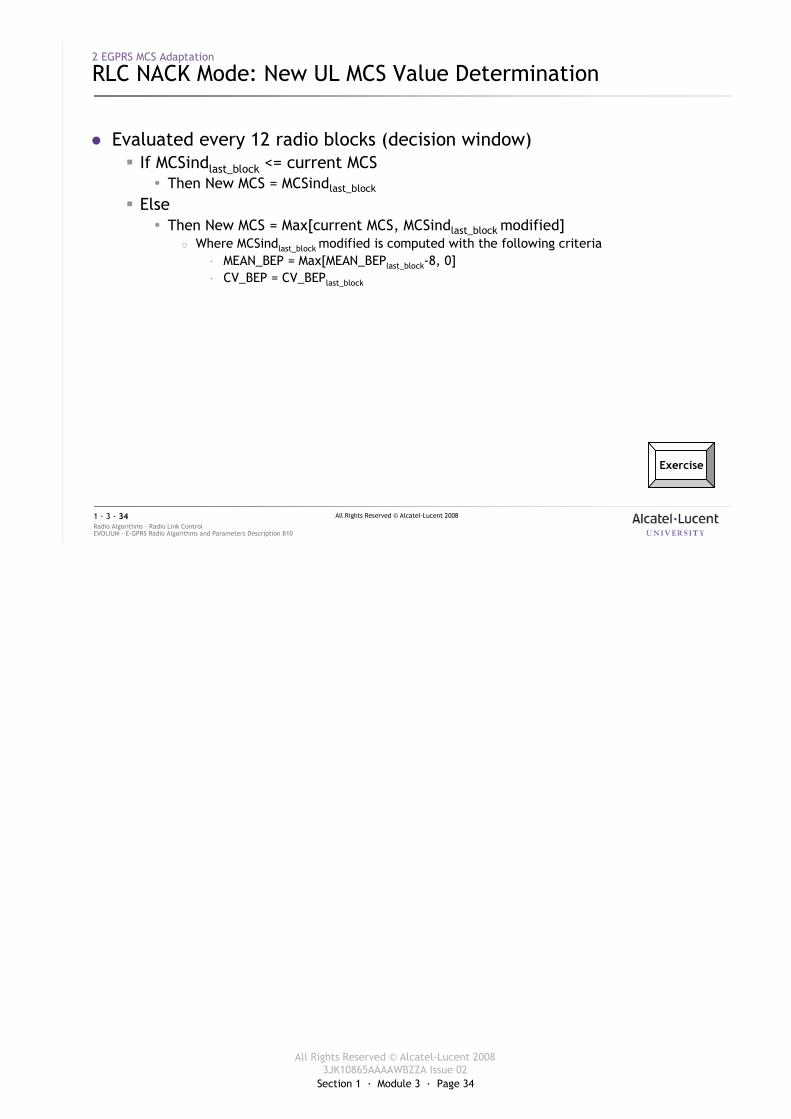
RLC NACK Mode: New UL MCS Value Determination
� Evaluated every 12 radio blocks (decision window)� If MCSindlast_block <= current MCS
� Then New MCS = MCSindlast_block
� Else� Then New MCS = Max[current MCS, MCSindlast_block modified]
� Where MCSindlast_block modified is computed with the following criteria· MEAN_BEP = Max[MEAN_BEPlast_block-8, 0]· CV_BEP = CV_BEPlast_block
Exercise
Section 1 · Module 3 · Page 35
All Rights Reserved © Alcatel-Lucent 20083JK10865AAAAWBZZA Issue 02
All Rights Reserved © Alcatel-Lucent 2008
EVOLIUM · E-GPRS Radio Algorithms and Parameters Description B10Radio Algorithms · Radio Link Control1 · 3 · 35
2 EGPRS MCS Adaptation
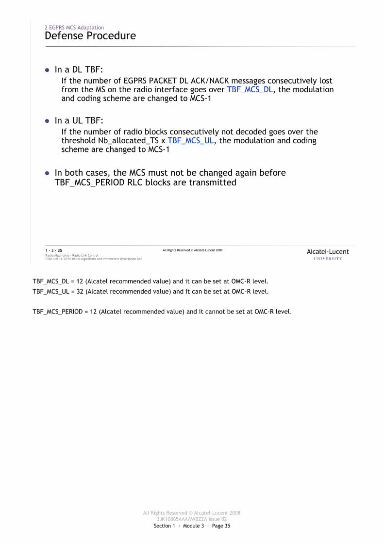
Defense Procedure
� In a DL TBF:If the number of EGPRS PACKET DL ACK/NACK messages consecutively lost from the MS on the radio interface goes over TBF_MCS_DL, the modulation and coding scheme are changed to MCS-1
� In a UL TBF:If the number of radio blocks consecutively not decoded goes over the threshold Nb_allocated_TS x TBF_MCS_UL, the modulation and coding scheme are changed to MCS-1
� In both cases, the MCS must not be changed again before TBF_MCS_PERIOD RLC blocks are transmitted
TBF_MCS_DL = 12 (Alcatel recommended value) and it can be set at OMC-R level.
TBF_MCS_UL = 32 (Alcatel recommended value) and it can be set at OMC-R level.
TBF_MCS_PERIOD = 12 (Alcatel recommended value) and it cannot be set at OMC-R level.
Section 1 · Module 3 · Page 36
All Rights Reserved © Alcatel-Lucent 20083JK10865AAAAWBZZA Issue 02
All Rights Reserved © Alcatel-Lucent 2008
EVOLIUM · E-GPRS Radio Algorithms and Parameters Description B10Radio Algorithms · Radio Link Control1 · 3 · 36
2 EGPRS MCS Adaptation
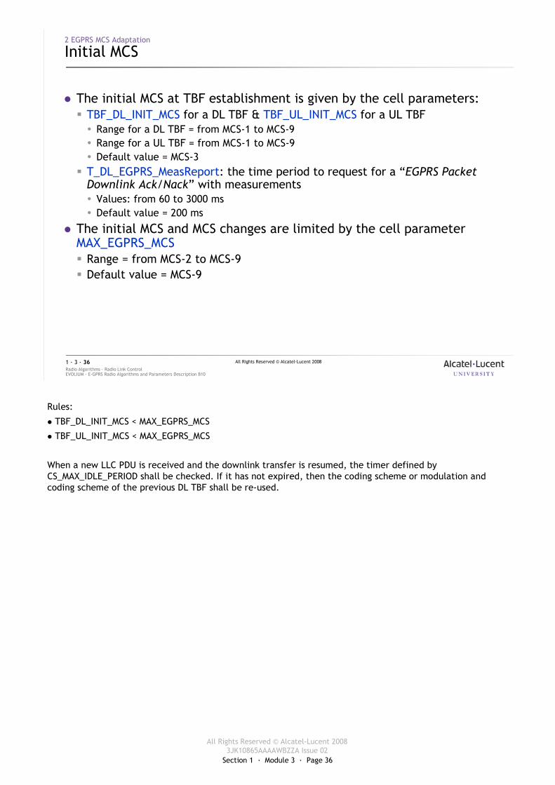
Initial MCS
� The initial MCS at TBF establishment is given by the cell parameters:� TBF_DL_INIT_MCS for a DL TBF & TBF_UL_INIT_MCS for a UL TBF� Range for a DL TBF = from MCS-1 to MCS-9� Range for a UL TBF = from MCS-1 to MCS-9� Default value = MCS-3
� T_DL_EGPRS_MeasReport: the time period to request for a “EGPRS Packet Downlink Ack/Nack” with measurements� Values: from 60 to 3000 ms� Default value = 200 ms
� The initial MCS and MCS changes are limited by the cell parameter MAX_EGPRS_MCS� Range = from MCS-2 to MCS-9� Default value = MCS-9
Rules:
� TBF_DL_INIT_MCS < MAX_EGPRS_MCS
� TBF_UL_INIT_MCS < MAX_EGPRS_MCS
When a new LLC PDU is received and the downlink transfer is resumed, the timer defined by CS_MAX_IDLE_PERIOD shall be checked. If it has not expired, then the coding scheme or modulation and coding scheme of the previous DL TBF shall be re-used.
Section 1 · Module 3 · Page 37
All Rights Reserved © Alcatel-Lucent 20083JK10865AAAAWBZZA Issue 02
All Rights Reserved © Alcatel-Lucent 2008
EVOLIUM · E-GPRS Radio Algorithms and Parameters Description B10Radio Algorithms · Radio Link Control1 · 3 · 37
3 RLC Blocks Retransmission
Section 1 · Module 3 · Page 38
All Rights Reserved © Alcatel-Lucent 20083JK10865AAAAWBZZA Issue 02
All Rights Reserved © Alcatel-Lucent 2008
EVOLIUM · E-GPRS Radio Algorithms and Parameters Description B10Radio Algorithms · Radio Link Control1 · 3 · 38
3 RLC Blocks Retransmission
New Modulation and Coding Schemes
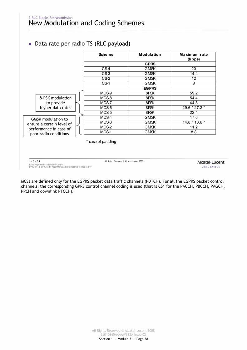
� Data rate per radio TS (RLC payload)
Scheme Modulation Maximum rate (kbps)
GPRS CS-4 GMSK 20 CS-3 GMSK 14.4 CS-2 GMSK 12 CS-1 GMSK 8
EGPRS MCS-9 8PSK 59.2 MCS-8 8PSK 54.4 MCS-7 8PSK 44.8 MCS-6 8PSK 29.6 / 27.2 * MCS-5 8PSK 22.4 MCS-4 GMSK 17.6 MCS-3 GMSK 14.8 / 13.6 * MCS-2 GMSK 11.2 MCS-1 GMSK 8.8
* case of padding
8-PSK modulation to provide
higher data rates
GMSK modulation to ensure a certain level of performance in case of poor radio conditions
MCSs are defined only for the EGPRS packet data traffic channels (PDTCH). For all the EGPRS packet control channels, the corresponding GPRS control channel coding is used (that is CS1 for the PACCH, PBCCH, PAGCH, PPCH and downlink PTCCH).
Section 1 · Module 3 · Page 39
All Rights Reserved © Alcatel-Lucent 20083JK10865AAAAWBZZA Issue 02
All Rights Reserved © Alcatel-Lucent 2008
EVOLIUM · E-GPRS Radio Algorithms and Parameters Description B10Radio Algorithms · Radio Link Control1 · 3 · 39
3 RLC Blocks Retransmission
New Modulation and Coding Schemes [cont.]
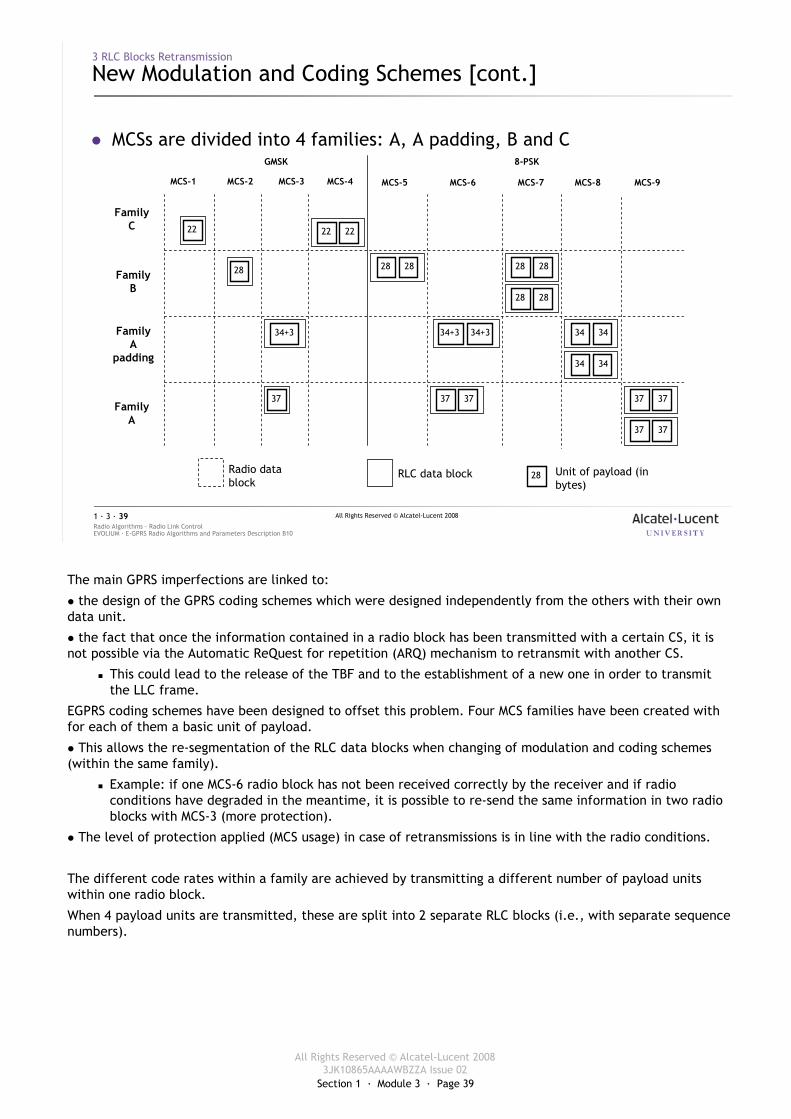
� MCSs are divided into 4 families: A, A padding, B and C
MCS-5 MCS-6 MCS-7 MCS-8 MCS-9MCS-1 MCS-2 MCS-3 MCS-4
FamilyC
FamilyB
FamilyA
padding
FamilyA
28
22
34+3
22 22
28 28
34+3 34+3
28 28
28 28
34 34
34 34
37 37 37 37 37
37 37
GMSK 8-PSK
28RLC data block Unit of payload (in bytes)
Radio data block
The main GPRS imperfections are linked to:
� the design of the GPRS coding schemes which were designed independently from the others with their own data unit.
� the fact that once the information contained in a radio block has been transmitted with a certain CS, it is not possible via the Automatic ReQuest for repetition (ARQ) mechanism to retransmit with another CS.
� This could lead to the release of the TBF and to the establishment of a new one in order to transmit the LLC frame.
EGPRS coding schemes have been designed to offset this problem. Four MCS families have been created with for each of them a basic unit of payload.
� This allows the re-segmentation of the RLC data blocks when changing of modulation and coding schemes (within the same family).
� Example: if one MCS-6 radio block has not been received correctly by the receiver and if radio conditions have degraded in the meantime, it is possible to re-send the same information in two radio blocks with MCS-3 (more protection).
� The level of protection applied (MCS usage) in case of retransmissions is in line with the radio conditions.
The different code rates within a family are achieved by transmitting a different number of payload units within one radio block.
When 4 payload units are transmitted, these are split into 2 separate RLC blocks (i.e., with separate sequence numbers).
Section 1 · Module 3 · Page 40
All Rights Reserved © Alcatel-Lucent 20083JK10865AAAAWBZZA Issue 02
All Rights Reserved © Alcatel-Lucent 2008
EVOLIUM · E-GPRS Radio Algorithms and Parameters Description B10Radio Algorithms · Radio Link Control1 · 3 · 40
3 RLC Blocks Retransmission
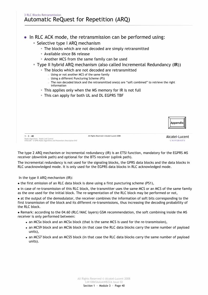
Automatic ReQuest for Repetition (ARQ)
� In RLC ACK mode, the retransmission can be performed using:� Selective type I ARQ mechanism
� The blocks which are not decoded are simply retransmitted � Available since B6 release� Another MCS from the same family can be used
� Type II hybrid ARQ mechanism (also called Incremental Redundancy (IR))� The blocks which are not decoded are retransmitted
� Using or not another MCS of the same family� Using a different Puncturing Scheme (PS)� The non decoded block and the retransmitted one(s) are “soft combined” to retrieve the right
information
� This applies only when the MS memory for IR is not full� This can apply for both UL and DL EGPRS TBF
Appendix
The type 2 ARQ mechanism or incremental redundancy (IR) is an ETSI function, mandatory for the EGPRS MS receiver (downlink path) and optional for the BTS receiver (uplink path).
The incremental redundancy is not used for the signaling blocks, the GPRS data blocks and the data blocks in RLC unacknowledged mode. It is only used for the EGPRS data blocks in RLC acknowledged mode.
In the type II ARQ mechanism (IR):
� the first emission of an RLC data block is done using a first puncturing scheme (PS1),
� in case of re-transmission of this RLC block, the transmitter uses the same MCS or an MCS of the same family as the one used for the initial block. The re-segmentation of the RLC block may be performed or not,
� at the output of the demodulator, the receiver combines the information of soft bits corresponding to the first transmission of the block and its different re-transmissions, thus increasing the decoding probability of the RLC block.
� Remark: according to the 04.60 (RLC/MAC layers) GSM recommendation, the soft combining inside the MS receiver is only performed between:
� an MCSx block and an MCSx block (that is the same MCS is used for the re-transmission),
� an MCS9 block and an MCS6 block (in that case the RLC data blocks carry the same number of payload units),
� an MCS7 block and an MCS5 block (in that case the RLC data blocks carry the same number of payload units).
Section 1 · Module 3 · Page 41
All Rights Reserved © Alcatel-Lucent 20083JK10865AAAAWBZZA Issue 02
All Rights Reserved © Alcatel-Lucent 2008
EVOLIUM · E-GPRS Radio Algorithms and Parameters Description B10Radio Algorithms · Radio Link Control1 · 3 · 41
3 RLC Blocks Retransmission
Type I ARQ Mechanism
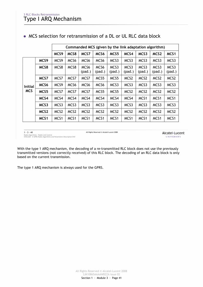
� MCS selection for retransmission of a DL or UL RLC data block
Commanded MCS (given by the link adaptation algorithm)
MCS9 MCS8 MCS7 MCS6 MCS5 MCS4 MCS3 MCS2 MCS1
MCS9 MCS9 MCS6 MCS6 MCS6 MCS3 MCS3 MCS3 MCS3 MCS3
MCS8 MCS8 MCS8 MCS6 (pad.)
MCS6 (pad.)
MCS3 (pad.)
MCS3 (pad.)
MCS3 (pad.)
MCS3 (pad.)
MCS3 (pad.)
MCS7 MCS7 MCS7 MCS7 MCS5 MCS5 MCS2 MCS2 MCS2 MCS2
MCS6 MCS9 MCS6 MCS6 MCS6 MCS3 MCS3 MCS3 MCS3 MCS3
MCS5 MCS7 MCS7 MCS7 MCS5 MCS5 MCS2 MCS2 MCS2 MCS2
MCS4 MCS4 MCS4 MCS4 MCS4 MCS4 MCS4 MCS1 MCS1 MCS1
MCS3 MCS3 MCS3 MCS3 MCS3 MCS3 MCS3 MCS3 MCS3 MCS3
MCS2 MCS2 MCS2 MCS2 MCS2 MCS2 MCS2 MCS2 MCS2 MCS2
Initial MCS
MCS1 MCS1 MCS1 MCS1 MCS1 MCS1 MCS1 MCS1 MCS1 MCS1
With the type 1 ARQ mechanism, the decoding of a re-transmitted RLC block does not use the previously transmitted versions (not correctly received) of this RLC block. The decoding of an RLC data block is only based on the current transmission.
The type 1 ARQ mechanism is always used for the GPRS.
Section 1 · Module 3 · Page 42
All Rights Reserved © Alcatel-Lucent 20083JK10865AAAAWBZZA Issue 02
All Rights Reserved © Alcatel-Lucent 2008
EVOLIUM · E-GPRS Radio Algorithms and Parameters Description B10Radio Algorithms · Radio Link Control1 · 3 · 42
3 RLC Blocks Retransmission
Type I ARQ Mechanism [cont.]
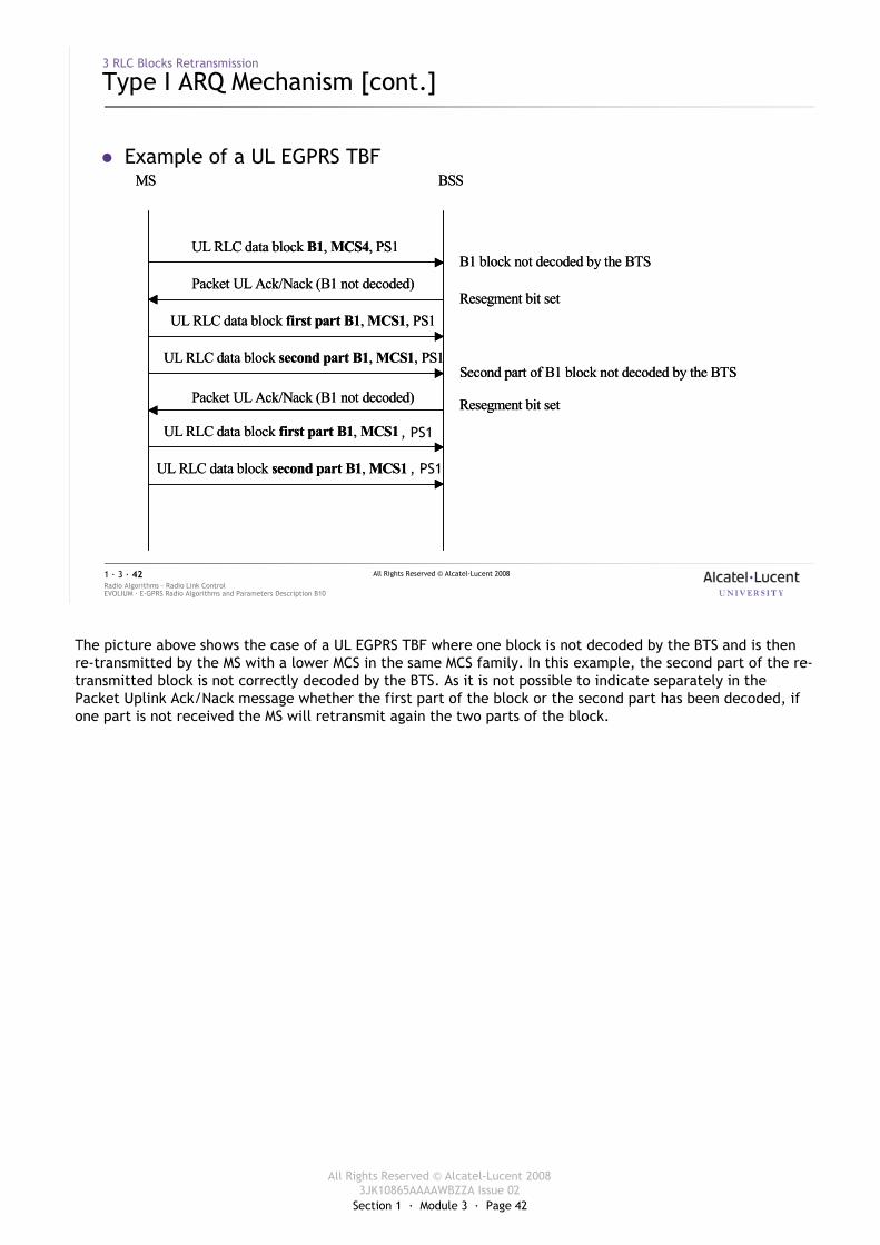
� Example of a UL EGPRS TBFMS BSS
UL RLC data block B1, MCS4, PS1
Packet UL Ack/Nack (B1 not decoded)
UL RLC data block first part B1, MCS1, PS1
UL RLC data block second part B1, MCS1, PS1
B1 block not decoded by the BTS
Resegment bit set
Second part of B1 block not decoded by the BTS
Packet UL Ack/Nack (B1 not decoded) Resegment bit set
UL RLC data block first part B1, MCS1
UL RLC data block second part B1, MCS1
MS BSS
UL RLC data block B1, MCS4, PS1
Packet UL Ack/Nack (B1 not decoded)
UL RLC data block first part B1, MCS1, PS1
UL RLC data block second part B1, MCS1, PS1
B1 block not decoded by the BTS
Resegment bit set
Second part of B1 block not decoded by the BTS
Packet UL Ack/Nack (B1 not decoded) Resegment bit set
UL RLC data block first part B1, MCS1
UL RLC data block second part B1, MCS1
, PS1
, PS1
The picture above shows the case of a UL EGPRS TBF where one block is not decoded by the BTS and is then re-transmitted by the MS with a lower MCS in the same MCS family. In this example, the second part of the re-transmitted block is not correctly decoded by the BTS. As it is not possible to indicate separately in the Packet Uplink Ack/Nack message whether the first part of the block or the second part has been decoded, if one part is not received the MS will retransmit again the two parts of the block.
Section 1 · Module 3 · Page 43
All Rights Reserved © Alcatel-Lucent 20083JK10865AAAAWBZZA Issue 02
All Rights Reserved © Alcatel-Lucent 2008
EVOLIUM · E-GPRS Radio Algorithms and Parameters Description B10Radio Algorithms · Radio Link Control1 · 3 · 43
3 RLC Blocks Retransmission
Type II ARQ Mechanism
� The MCS used to re-transmit a DL RLC data block depends on:� The initial MCS used to send this RLC data block� The resegmentation allowed or not
� The DL resegmentation is allowed If EN_FULL_IR_DL = disabled� The UL resegmentation is allowed If EN_RESEGMENTATION_UL= enabled
� The possible memory shortage in the MS (case of a DL EGPRS TBF)� MS OUT OF MEMORY = On, in the EGPRS packet DL Ack/Nack message
� The MCS commanded by the link adaptation algorithm (refer to session 2 EGPRS MCS Adaptation)
� As IR is optional in UL, the feature can be enabled/disabled using the Cell parameter EN_IR_UL
Modified B10
Modified B10
B10
Modified B10
The TRX manages the IR UL. Indeed, the TRX decodes the RLC/MAC header of all the UL RLC/MAC data blocks received on each PDCH to know which TBF the RLC data block(s) pertain.
For each TBF, the maximum number of different RLC data blocks stored is equal to the window size which depends on the maximum number of RTSs used in uplink (512 for 4 TS).
The TRX is able to store 4,000 RLC data blocks which have not been correctly decoded. If an RLC data block is received with the same PS as an already received RLC data block belonging to the same TBF, only the last instance is taken into account.
EN_FULL_IR_DL, parameter changed from BSS level in B9 to Cell Level in B10.
EN_RESEGMENTATION_UL, parameter changed from BSS level in B9 to Cell Level in B10.
Section 1 · Module 3 · Page 44
All Rights Reserved © Alcatel-Lucent 20083JK10865AAAAWBZZA Issue 02
All Rights Reserved © Alcatel-Lucent 2008
EVOLIUM · E-GPRS Radio Algorithms and Parameters Description B10Radio Algorithms · Radio Link Control1 · 3 · 44
3 RLC Blocks Retransmission
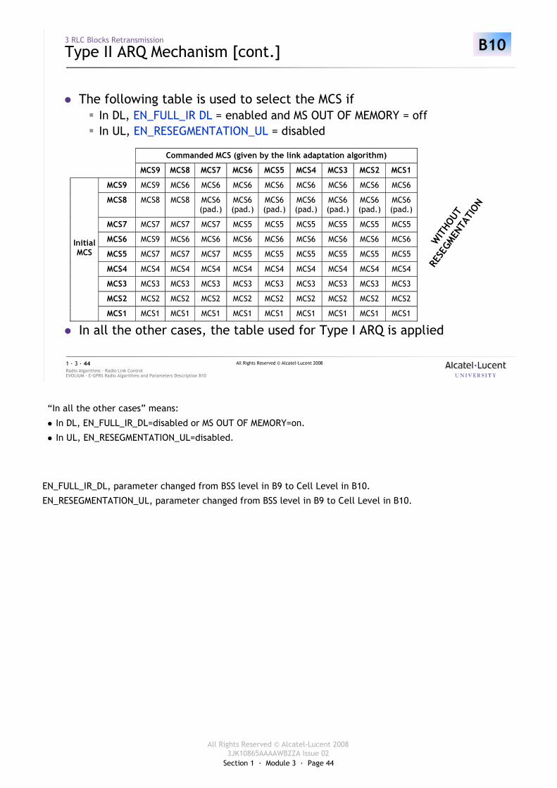
Type II ARQ Mechanism [cont.]
� The following table is used to select the MCS if� In DL, EN_FULL_IR DL = enabled and MS OUT OF MEMORY = off� In UL, EN_RESEGMENTATION_UL = disabled
� In all the other cases, the table used for Type I ARQ is applied
Commanded MCS (given by the link adaptation algorithm)
MCS9 MCS8 MCS7 MCS6 MCS5 MCS4 MCS3 MCS2 MCS1
MCS9 MCS9 MCS6 MCS6 MCS6 MCS6 MCS6 MCS6 MCS6 MCS6
MCS8 MCS8 MCS8 MCS6 (pad.)
MCS6 (pad.)
MCS6 (pad.)
MCS6 (pad.)
MCS6 (pad.)
MCS6 (pad.)
MCS6 (pad.)
MCS7 MCS7 MCS7 MCS7 MCS5 MCS5 MCS5 MCS5 MCS5 MCS5
MCS6 MCS9 MCS6 MCS6 MCS6 MCS6 MCS6 MCS6 MCS6 MCS6
MCS5 MCS7 MCS7 MCS7 MCS5 MCS5 MCS5 MCS5 MCS5 MCS5
MCS4 MCS4 MCS4 MCS4 MCS4 MCS4 MCS4 MCS4 MCS4 MCS4
MCS3 MCS3 MCS3 MCS3 MCS3 MCS3 MCS3 MCS3 MCS3 MCS3
MCS2 MCS2 MCS2 MCS2 MCS2 MCS2 MCS2 MCS2 MCS2 MCS2
Initial MCS
MCS1 MCS1 MCS1 MCS1 MCS1 MCS1 MCS1 MCS1 MCS1 MCS1
WIT
HOUT
RESE
GMEN
TATI
ON
B10
“In all the other cases” means:
� In DL, EN_FULL_IR_DL=disabled or MS OUT OF MEMORY=on.
� In UL, EN_RESEGMENTATION_UL=disabled.
EN_FULL_IR_DL, parameter changed from BSS level in B9 to Cell Level in B10.
EN_RESEGMENTATION_UL, parameter changed from BSS level in B9 to Cell Level in B10.
Section 1 · Module 3 · Page 45
All Rights Reserved © Alcatel-Lucent 20083JK10865AAAAWBZZA Issue 02
All Rights Reserved © Alcatel-Lucent 2008
EVOLIUM · E-GPRS Radio Algorithms and Parameters Description B10Radio Algorithms · Radio Link Control1 · 3 · 45
3 RLC Blocks Retransmission
Type II ARQ Mechanism [cont.]
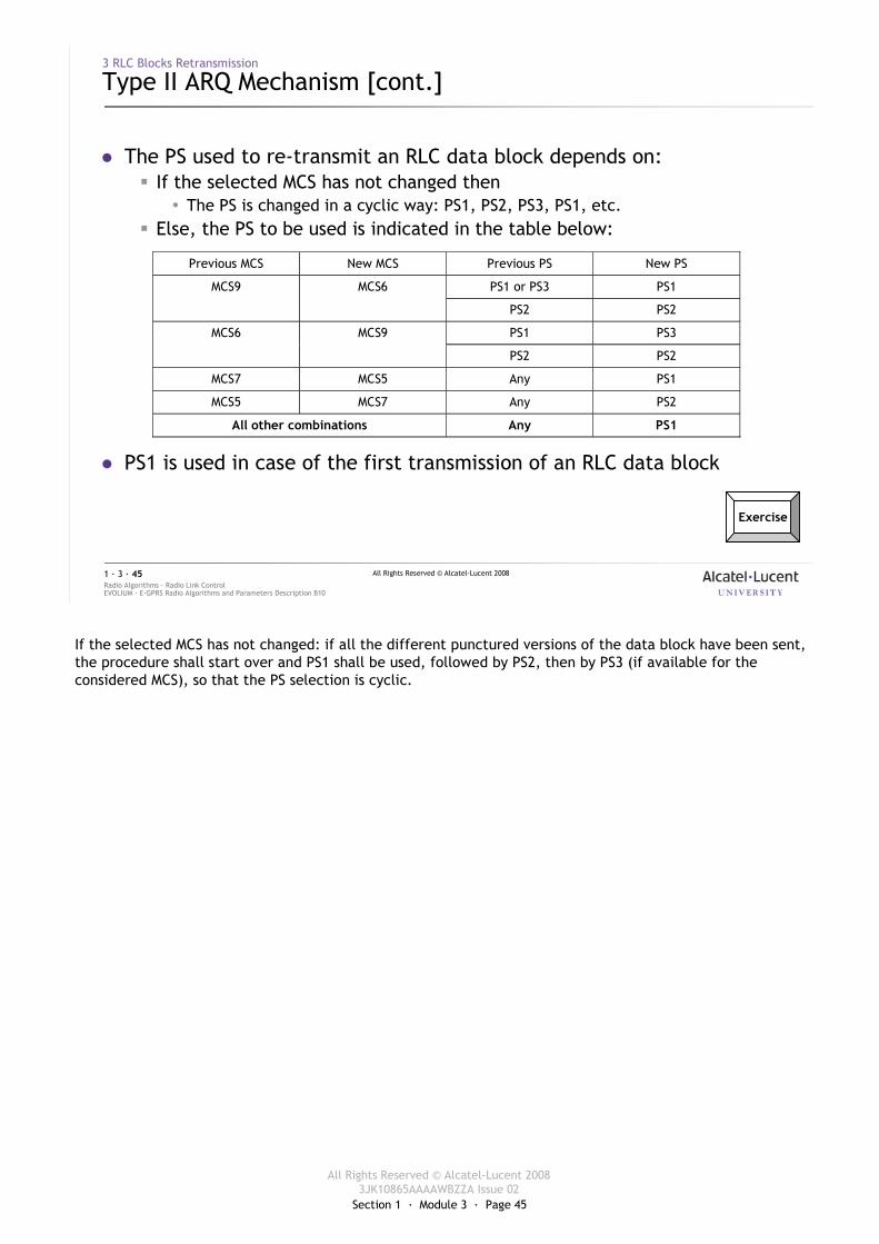
� The PS used to re-transmit an RLC data block depends on:� If the selected MCS has not changed then
� The PS is changed in a cyclic way: PS1, PS2, PS3, PS1, etc.� Else, the PS to be used is indicated in the table below:
� PS1 is used in case of the first transmission of an RLC data block
Exercise
Previous MCS New MCS Previous PS New PS
PS1 or PS3 PS1 MCS9 MCS6
PS2 PS2
PS1 PS3 MCS6 MCS9
PS2 PS2
MCS7 MCS5 Any PS1
MCS5 MCS7 Any PS2
All other combinations Any PS1
If the selected MCS has not changed: if all the different punctured versions of the data block have been sent, the procedure shall start over and PS1 shall be used, followed by PS2, then by PS3 (if available for the considered MCS), so that the PS selection is cyclic.

Section 1 · Module 3 · Page 46
All Rights Reserved © Alcatel-Lucent 20083JK10865AAAAWBZZA Issue 02
All Rights Reserved © Alcatel-Lucent 2008
EVOLIUM · E-GPRS Radio Algorithms and Parameters Description B10Radio Algorithms · Radio Link Control1 · 3 · 46
4 UL Power Control
Section 1 · Module 3 · Page 47
All Rights Reserved © Alcatel-Lucent 20083JK10865AAAAWBZZA Issue 02
All Rights Reserved © Alcatel-Lucent 2008
EVOLIUM · E-GPRS Radio Algorithms and Parameters Description B10Radio Algorithms · Radio Link Control1 · 3 · 47
4 UL Power Control
Measurements
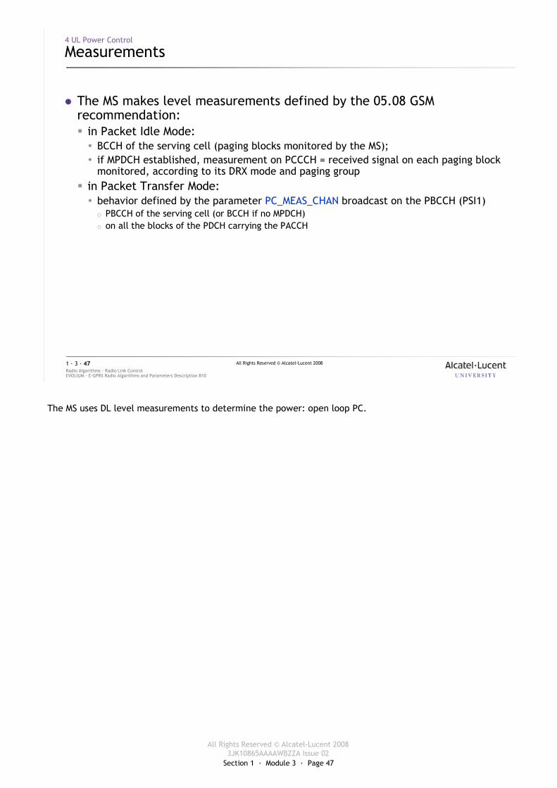
� The MS makes level measurements defined by the 05.08 GSM recommendation:� in Packet Idle Mode:� BCCH of the serving cell (paging blocks monitored by the MS);� if MPDCH established, measurement on PCCCH = received signal on each paging block
monitored, according to its DRX mode and paging group� in Packet Transfer Mode:� behavior defined by the parameter PC_MEAS_CHAN broadcast on the PBCCH (PSI1)
� PBCCH of the serving cell (or BCCH if no MPDCH)� on all the blocks of the PDCH carrying the PACCH
The MS uses DL level measurements to determine the power: open loop PC.
Section 1 · Module 3 · Page 48
All Rights Reserved © Alcatel-Lucent 20083JK10865AAAAWBZZA Issue 02
All Rights Reserved © Alcatel-Lucent 2008
EVOLIUM · E-GPRS Radio Algorithms and Parameters Description B10Radio Algorithms · Radio Link Control1 · 3 · 48
4 UL Power Control
Averaging
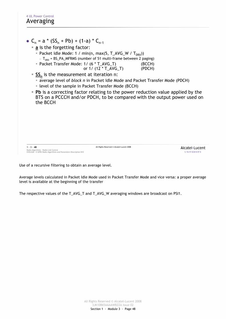
� Cn = a * (SSn + Pb) + (1-a) * Cn-1� a is the forgetting factor:� Packet Idle Mode: 1 / min(n, max(5, T_AVG_W / TDRX))
� TDRX = BS_PA_MFRMS (number of 51 multi-frame between 2 paging)� Packet Transfer Mode: 1/ (6 * T_AVG_T) (BCCH)
or 1/ (12 * T_AVG_T) (PDCH)� SSn is the measurement at iteration n:� average level of block n in Packet Idle Mode and Packet Transfer Mode (PDCH)� level of the sample in Packet Transfer Mode (BCCH)
� Pb is a correcting factor relating to the power reduction value applied by the BTS on a PCCCH and/or PDCH, to be compared with the output power used on the BCCH
Use of a recursive filtering to obtain an average level.
Average levels calculated in Packet Idle Mode used in Packet Transfer Mode and vice versa: a proper average level is available at the beginning of the transfer
The respective values of the T_AVG_T and T_AVG_W averaging windows are broadcast on PSI1.
Section 1 · Module 3 · Page 49
All Rights Reserved © Alcatel-Lucent 20083JK10865AAAAWBZZA Issue 02
All Rights Reserved © Alcatel-Lucent 2008
EVOLIUM · E-GPRS Radio Algorithms and Parameters Description B10Radio Algorithms · Radio Link Control1 · 3 · 49
4 UL Power Control
MS Power
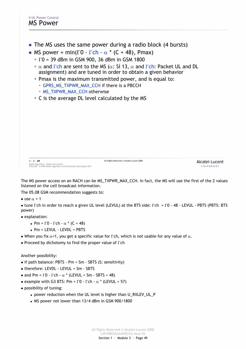
� The MS uses the same power during a radio block (4 bursts)� MS power = min(Γ0 - Γch - α * (C + 48), Pmax)
� Γ0 = 39 dBm in GSM 900, 36 dBm in GSM 1800� α and Γch are sent to the MS (α: SI 13, α and Γch: Packet UL and DL
assignment) and are tuned in order to obtain a given behavior� Pmax is the maximum transmitted power, and is equal to:� GPRS_MS_TXPWR_MAX_CCH if there is a PBCCH� MS_TXPWR_MAX_CCH otherwise
� C is the average DL level calculated by the MS
The MS power access on an RACH can be MS_TXPWR_MAX_CCH. In fact, the MS will use the first of the 2 values listened on the cell broadcast information.
The 05.08 GSM recommendation suggests to:
� use α = 1
� tune Γch in order to reach a given UL level (LEVUL) at the BTS side: Γch = Γ0 - 48 - LEVUL - PBTS (PBTS: BTS power)
� explanation:
� Pm = Γ0 - Γch - α * (C + 48)
� Pm = LEVUL - LEVDL + PBTS
� When you fix α=1, you get a specific value for Γch, which is not usable for any value of α.
� Proceed by dichotomy to find the proper value of Γch
Another possibility:
� if path balance: PBTS - Pm = Sm - SBTS (S: sensitivity)
� therefore: LEVDL - LEVUL = Sm - SBTS
� and Pm = Γ0 - Γch - α * (LEVUL + Sm - SBTS + 48)
� example with G3 BTS: Pm = Γ0 - Γch - α * (LEVUL + 57)
� possibility of tuning:
� power reduction when the UL level is higher than U_RXLEV_UL_P
� MS power not lower than 13/4 dBm in GSM 900/1800

Section 1 · Module 3 · Page 50
All Rights Reserved © Alcatel-Lucent 20083JK10865AAAAWBZZA Issue 02
All Rights Reserved © Alcatel-Lucent 2008
EVOLIUM · E-GPRS Radio Algorithms and Parameters Description B10Radio Algorithms · Radio Link Control1 · 3 · 50
5 NC0 Cell Selection and Reselection
Section 1 · Module 3 · Page 51
All Rights Reserved © Alcatel-Lucent 20083JK10865AAAAWBZZA Issue 02
All Rights Reserved © Alcatel-Lucent 2008
EVOLIUM · E-GPRS Radio Algorithms and Parameters Description B10Radio Algorithms · Radio Link Control1 · 3 · 51
5 NC0 Cell Selection and Reselection
Introduction
� 2 kinds of selection – reselection are implemented in the Alcatel-LucentBSS:� NC0
� The MS performs autonomous cell reselection� All the algorithms (criteria computation, triggering, target cell choice) are
implemented in the MS� No measurement reporting
� NC2� The network (MFS) controls the cell reselection� All the algorithms (criteria computation, triggering, target cell choice) are
implemented in the MFS� The MS sends periodically measurement reports
� The main important parameters involved in the cell selection andreselection are broadcast in PSI3 & PSI3bis (if PBCCH) or in SI3 (if BCCH).
� The GPRS neighboring cells list is identical to the GSM one
Further details concerning Cell selection and Cell reselection in case of PBCCH in the appendix.
Section 1 · Module 3 · Page 52
All Rights Reserved © Alcatel-Lucent 20083JK10865AAAAWBZZA Issue 02
All Rights Reserved © Alcatel-Lucent 2008
EVOLIUM · E-GPRS Radio Algorithms and Parameters Description B10Radio Algorithms · Radio Link Control1 · 3 · 52
5 NC0 Cell Selection and Reselection
Principles
� Procedures defined in the 05.08 GSM recommendation
� Cell selection:� made using the C1 criterion as for GSM
� Cell reselection:� made using the C1 and C2 criteria as for GSM in the serving cell
In GSM
C1 = A - Max (0,B) with:
� A = RLA_C - RXLEV_ACCESS_MIN
� B = MS_TXPWR_MAX_CCH - MS_TXPWR_MAX + POWER_OFFSET(1800)
C2 = C1 + CELL_RESELECT_OFFSET - TEMPORARY_OFFSET(T) when Penalty_time<31
C2 = C1 - CELL_RESELECT_OFFSET when Penalty_Time=31
In GPRS ready and standby states, cell reselection is performed by the MS except for a class A MS while in dedicated mode of a circuit-switched connection, in which case the cell is determined by the network according to the handover procedures.
For a class B MS which can combine GSM and GPRS states, C1 criterion is used when the MS simultaneously attached to both the network and the MS is in Packet Idle Mode (refer to GSM 05.08).
Section 1 · Module 3 · Page 53
All Rights Reserved © Alcatel-Lucent 20083JK10865AAAAWBZZA Issue 02
All Rights Reserved © Alcatel-Lucent 2008
EVOLIUM · E-GPRS Radio Algorithms and Parameters Description B10Radio Algorithms · Radio Link Control1 · 3 · 53
5 NC0 Cell Selection and Reselection
Selection
� Criteria computation:
� Without PBCCH� C1 = (RLA_C – RXLEV_ACCESS_MIN) – max (0, MS_TXPWR_MAX_CCCH – P)� RLA_C: average DL level received
� Cell choice: the best cell is the cell with the highest C1
C1 is the same as in GSM except that:
� A = RLA_P – GPRS_RXLEV_ACCESS_MIN: “listening capacity of MS in the cell”
� B = GPRS_MS_TXPWR_MAX_CCH – P: “talking capacity of MS in the cell”
� C1 shall be positive and as high as possible
In Packet Idle Mode, the MS shall make one measurement for each BCCH carrier monitored every 4 seconds, as well as more than one sample per second for each BCCH carrier.
A list of 6 strongest cells shall be kept updated at a rate of at least one update per running average period.
In Packet Transfer Mode, the MS shall monitor a list of 6 strongest non-serving cell BCCH carriers. It shall attempt to check the BSIC for each of these 6 strongest cells at least once every 10 seconds.
Section 1 · Module 3 · Page 54
All Rights Reserved © Alcatel-Lucent 20083JK10865AAAAWBZZA Issue 02
All Rights Reserved © Alcatel-Lucent 2008
EVOLIUM · E-GPRS Radio Algorithms and Parameters Description B10Radio Algorithms · Radio Link Control1 · 3 · 54
5 NC0 Cell Selection and Reselection
Reselection Criteria Computation Without PBCCH
� If CELL_RESELECT_PARAM_IND=not present then C2=C1 else:� C2 = C1 + CELL_RESELECT_OFFSET - TEMPORARY_OFFSET(T)
(if PENALTY_TIME <> 31) � if T > PENALTY_TIME, TEMPORARY_OFFSET(T)=0� used to avoid locating on “transient cell”� CELL_RESELECT_OFFSET used to favor a cell among others (e.g., micro-cell vs.
umbrella, once T > PENALTY_TIME)� C2 = C1 - CELL_RESELECT_OFFSET
(if PENALTY_TIME = 31) � CELL_RESELECT_OFFSET used to handicap some cells among others
The same algorithm is used in case the MS is in GSM Idle Mode.
Section 1 · Module 3 · Page 55
All Rights Reserved © Alcatel-Lucent 20083JK10865AAAAWBZZA Issue 02
All Rights Reserved © Alcatel-Lucent 2008
EVOLIUM · E-GPRS Radio Algorithms and Parameters Description B10Radio Algorithms · Radio Link Control1 · 3 · 55
5 NC0 Cell Selection and Reselection
Target Cell Choice Without PBCCH
� The MS triggers a cell reselection if:� C1(serving) <0and/or� In Standby Mode� C2(neighbor) > C2(serving) if cells belong to a same RA� C2(neighbor) > C2(serving)+CELL_RESELECT_HYSTERESIS if cells from different RAs
� In Ready Mode� C2(neighbor) > C2(serving)+CELL_RESELECT_HYSTERESIS even if cells belong to a
same RA
� Cell choice: the best cell is the cell with the highest C2
The normal procedures apply in case of Cell reselection for a DTM capable MS in PTM.
Section 1 · Module 3 · Page 56
All Rights Reserved © Alcatel-Lucent 20083JK10865AAAAWBZZA Issue 02
All Rights Reserved © Alcatel-Lucent 2008
EVOLIUM · E-GPRS Radio Algorithms and Parameters Description B10Radio Algorithms · Radio Link Control1 · 3 · 56
5 NC0 Cell Selection and Reselection
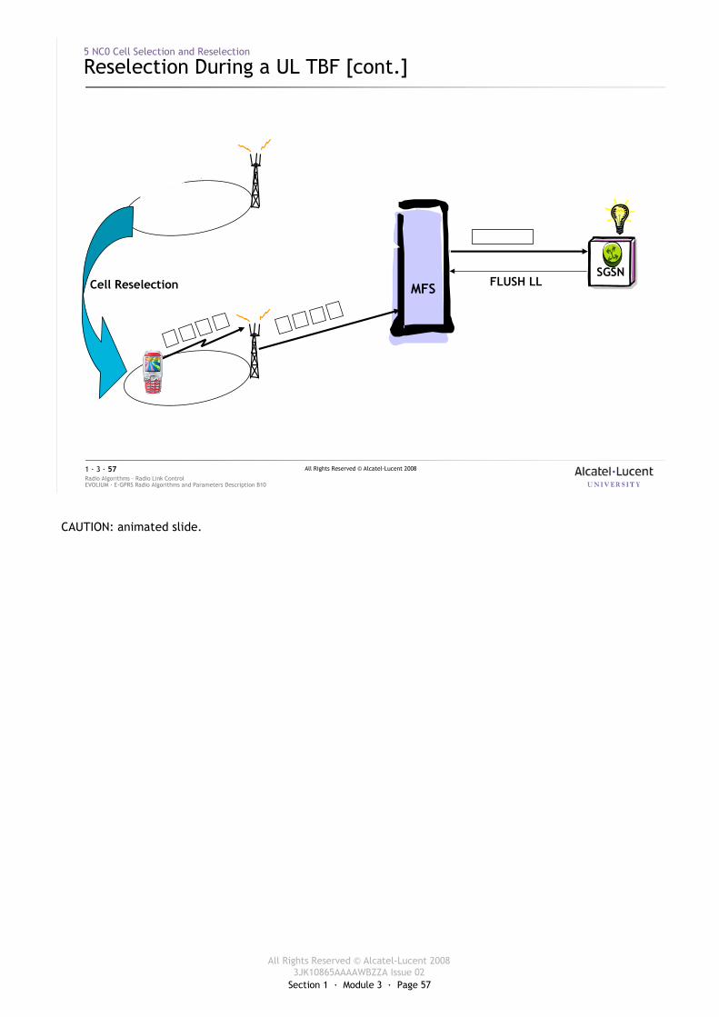
Reselection During a UL TBF
� UL TBF:� MFS: after a cell reselection, the MFS receives no more data in the UL blocks
allocated to the MS => TBF release� MS: in the new cell, after the SI messages acquisition, a new UL TBF is
established� SGSN: the SGSN is informed of the cell change when receiving an LLC unit
from the MS in the new cell. Then the SGSN notifies the BSS about the cell change (FLUSH PDU)
After a TBF release, it is up to the originator to reinitiate the transfer: the MS in the UL, the SGSN in the DL.
Section 1 · Module 3 · Page 57
All Rights Reserved © Alcatel-Lucent 20083JK10865AAAAWBZZA Issue 02
All Rights Reserved © Alcatel-Lucent 2008
EVOLIUM · E-GPRS Radio Algorithms and Parameters Description B10Radio Algorithms · Radio Link Control1 · 3 · 57
5 NC0 Cell Selection and Reselection
Reselection During a UL TBF [cont.]
SGSNCell Reselection
?
FLUSH LLMFS
CAUTION: animated slide.
Section 1 · Module 3 · Page 58
All Rights Reserved © Alcatel-Lucent 20083JK10865AAAAWBZZA Issue 02
All Rights Reserved © Alcatel-Lucent 2008
EVOLIUM · E-GPRS Radio Algorithms and Parameters Description B10Radio Algorithms · Radio Link Control1 · 3 · 58
5 NC0 Cell Selection and Reselection
Reselection During a DL TBF
� DL TBF:� MFS: after a cell reselection, the MFS receives no more acknowledgements
from the MS => abnormal TBF release� MS: in the new cell, after the SI messages acquisition, a UL TBF is established
to send a cell update to the SGSN (MS in Ready state)� SGSN: when the SGSN is informed of a cell change it sends a message to the
MFS to discard LLC units stored for the MS in the old cell (FLUSH PDU)� The SGSN resumes the DL transfer by sending a DL LLC unit => DL TBF
establishment in the new cell
After a TBF release, it is up to the originator to reinitiate the transfer: the MS in the UL, the SGSN in the DL.
Section 1 · Module 3 · Page 59
All Rights Reserved © Alcatel-Lucent 20083JK10865AAAAWBZZA Issue 02
All Rights Reserved © Alcatel-Lucent 2008
EVOLIUM · E-GPRS Radio Algorithms and Parameters Description B10Radio Algorithms · Radio Link Control1 · 3 · 59
5 NC0 Cell Selection and Reselection
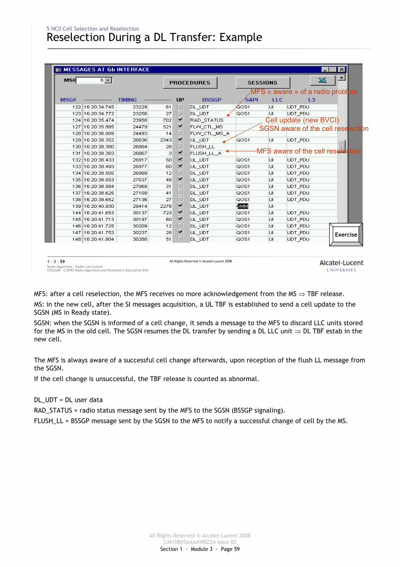
Reselection During a DL Transfer: Example
Cell update (new BVCI)SGSN aware of the cell reselection
MFS « aware » of a radio problem
MFS aware of the cell reselection
Exercise
MFS: after a cell reselection, the MFS receives no more acknowledgement from the MS ⇒ TBF release.
MS: in the new cell, after the SI messages acquisition, a UL TBF is established to send a cell update to the SGSN (MS in Ready state).
SGSN: when the SGSN is informed of a cell change, it sends a message to the MFS to discard LLC units stored for the MS in the old cell. The SGSN resumes the DL transfer by sending a DL LLC unit ⇒ DL TBF estab in the new cell.
The MFS is always aware of a successful cell change afterwards, upon reception of the flush LL message from the SGSN.
If the cell change is unsuccessful, the TBF release is counted as abnormal.
DL_UDT = DL user data
RAD_STATUS = radio status message sent by the MFS to the SGSN (BSSGP signaling).
FLUSH_LL = BSSGP message sent by the SGSN to the MFS to notify a successful change of cell by the MS.
Section 1 · Module 3 · Page 60
All Rights Reserved © Alcatel-Lucent 20083JK10865AAAAWBZZA Issue 02
All Rights Reserved © Alcatel-Lucent 2008
EVOLIUM · E-GPRS Radio Algorithms and Parameters Description B10Radio Algorithms · Radio Link Control1 · 3 · 60
5 NC0 Cell Selection and Reselection
NACC and (P)SI Status
� 2 features are available to reduce the duration of the reselection� NACC: Network Assisted Cell Change� If EN_NACC = enabled then
� before the cell reselection, � in the serving cell, � the network sends to the MS a part of the SI messages of the new cell
� (P)SI Status: (Packet) System Info Status� If EN_PSI_STATUS = enabled then
� after the transfer resumption,� in the target cell,� the MS can ask the network to send it:
· the remaining PSI messages if PBCCH is present· the remaining SI messages otherwise
B10
The NACC procedure is a new feature standardized in Release 4, mandatory for Release 4 onwards mobile stations supporting GERAN Feature Package 1.
The Packet PSI Status procedure is a feature standardized from Release 97 onwards, optional for Release 97, Release 98 and Release 99 MS, and mandatory for Release 4 onwards MS supporting GERAN Feature Package 1.
The Packet SI Status procedure is a new feature standardized in Release 4, mandatory for Release 4 onwards mobile stations supporting GERAN Feature Package 1.
NACC and (P)SI Status features are supported only if:
� The MS is neither in dedicated mode nor Dual Transfer Mode
� The MS is in NCO or NC1 mode
� The MS is in Packet Transfer Mode.
Section 1 · Module 3 · Page 61
All Rights Reserved © Alcatel-Lucent 20083JK10865AAAAWBZZA Issue 02
All Rights Reserved © Alcatel-Lucent 2008
EVOLIUM · E-GPRS Radio Algorithms and Parameters Description B10Radio Algorithms · Radio Link Control1 · 3 · 61
5 NC0 Cell Selection and Reselection
NACC and (P)SI Status [cont.]
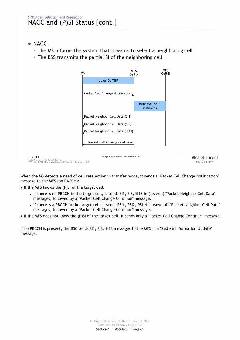
� NACC� The MS informs the system that it wants to select a neighboring cell� The BSS transmits the partial SI of the neighboring cell
MS MFSCell A
UL or DL TBF
Packet Cell Change Notification
Retrieval of SI instances
Packet Neighbor Cell Data (SI1)
Packet Neighbor Cell Data (SI3)
Packet Neighbor Cell Data (SI13)
Packet Cell Change Continue
MFSCell B
When the MS detects a need of cell reselection in transfer mode, it sends a "Packet Cell Change Notification" message to the MFS (on PACCH):
� If the MFS knows the (P)SI of the target cell:
� If there is no PBCCH in the target cell, it sends SI1, SI3, SI13 in (several) "Packet Neighbor Cell Data" messages, followed by a "Packet Cell Change Continue" message.
� If there is a PBCCH in the target cell, it sends PSI1, PSI2, PSI14 in (several) "Packet Neighbor Cell Data" messages, followed by a "Packet Cell Change Continue" message.
� If the MFS does not know the (P)SI of the target cell, it sends only a "Packet Cell Change Continue" message.
If no PBCCH is present, the BSC sends SI1, SI3, SI13 messages to the MFS in a "System Information Update" message.
Section 1 · Module 3 · Page 62
All Rights Reserved © Alcatel-Lucent 20083JK10865AAAAWBZZA Issue 02
All Rights Reserved © Alcatel-Lucent 2008
EVOLIUM · E-GPRS Radio Algorithms and Parameters Description B10Radio Algorithms · Radio Link Control1 · 3 · 62
5 NC0 Cell Selection and Reselection
NACC and (P)SI Status [cont.]
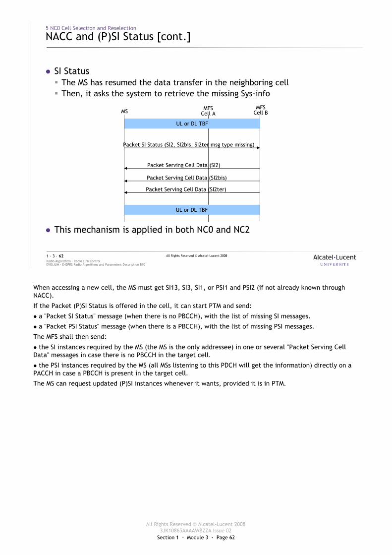
� SI Status� The MS has resumed the data transfer in the neighboring cell� Then, it asks the system to retrieve the missing Sys-info
� This mechanism is applied in both NC0 and NC2
MS MFSCell A
MFSCell B
Packet SI Status (SI2, SI2bis, SI2ter msg type missing)
Packet Serving Cell Data (SI2)
Packet Serving Cell Data (SI2bis)
Packet Serving Cell Data (SI2ter)
UL or DL TBF
UL or DL TBF
When accessing a new cell, the MS must get SI13, SI3, SI1, or PSI1 and PSI2 (if not already known through NACC).
If the Packet (P)SI Status is offered in the cell, it can start PTM and send:
� a "Packet SI Status" message (when there is no PBCCH), with the list of missing SI messages.
� a "Packet PSI Status" message (when there is a PBCCH), with the list of missing PSI messages.
The MFS shall then send:
� the SI instances required by the MS (the MS is the only addressee) in one or several "Packet Serving Cell Data" messages in case there is no PBCCH in the target cell.
� the PSI instances required by the MS (all MSs listening to this PDCH will get the information) directly on a PACCH in case a PBCCH is present in the target cell.
The MS can request updated (P)SI instances whenever it wants, provided it is in PTM.

Section 1 · Module 3 · Page 63
All Rights Reserved © Alcatel-Lucent 20083JK10865AAAAWBZZA Issue 02
All Rights Reserved © Alcatel-Lucent 2008
EVOLIUM · E-GPRS Radio Algorithms and Parameters Description B10Radio Algorithms · Radio Link Control1 · 3 · 63
6 NC2 Cell Reselection
Section 1 · Module 3 · Page 64
All Rights Reserved © Alcatel-Lucent 20083JK10865AAAAWBZZA Issue 02
All Rights Reserved © Alcatel-Lucent 2008
EVOLIUM · E-GPRS Radio Algorithms and Parameters Description B10Radio Algorithms · Radio Link Control1 · 3 · 64
6 NC2 Cell Reselection
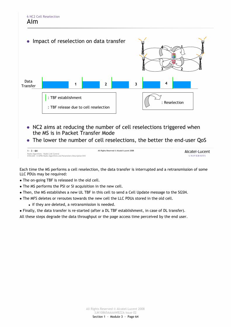
Aim
� Impact of reselection on data transfer
� NC2 aims at reducing the number of cell reselections triggered whenthe MS is in Packet Transfer Mode
� The lower the number of cell reselections, the better the end-user QoS
DataTransfer
: TBF establishment
: TBF release due to cell reselection: Reselection
1 2 3
1
23
4
4
Each time the MS performs a cell reselection, the data transfer is interrupted and a retransmission of some LLC PDUs may be required:
� The on-going TBF is released in the old cell.
� The MS performs the PSI or SI acquisition in the new cell.
� Then, the MS establishes a new UL TBF in this cell to send a Cell Update message to the SGSN.
� The MFS deletes or reroutes towards the new cell the LLC PDUs stored in the old cell.
� if they are deleted, a retransmission is needed.
� Finally, the data transfer is re-started (after a DL TBF establishment, in case of DL transfer).
All these steps degrade the data throughput or the page access time perceived by the end user.
Section 1 · Module 3 · Page 65
All Rights Reserved © Alcatel-Lucent 20083JK10865AAAAWBZZA Issue 02
All Rights Reserved © Alcatel-Lucent 2008
EVOLIUM · E-GPRS Radio Algorithms and Parameters Description B10Radio Algorithms · Radio Link Control1 · 3 · 65
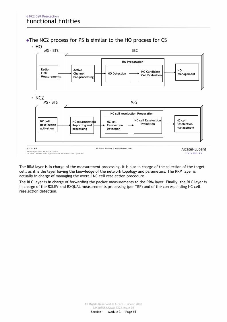
�The NC2 process for PS is similar to the HO process for CS� HO
� NC2
6 NC2 Cell Reselection
Functional Entities
RadioLink Measurements
ActiveChannelPre-processing
HO Detection HO CandidateCell Evaluation
HO management
HO Preparation
MS - BTS BSC
MS - BTS MFS
NC cell Reselectionactivation
NC measurementReporting andprocessing
NC cellReselection Detection
NC cell ReselectionEvaluation
NC cell Reselectionmanagement
NC cell reselection Preparation
The RRM layer is in charge of the measurement processing. It is also in charge of the selection of the target cell, as it is the layer having the knowledge of the network topology and parameters. The RRM layer is actually in charge of managing the overall NC cell reselection procedure.
The RLC layer is in charge of forwarding the packet measurements to the RRM layer. Finally, the RLC layer is in charge of the RXLEV and RXQUAL measurements processing (per TBF) and of the corresponding NC cell reselection detection.
Section 1 · Module 3 · Page 66
All Rights Reserved © Alcatel-Lucent 20083JK10865AAAAWBZZA Issue 02
All Rights Reserved © Alcatel-Lucent 2008
EVOLIUM · E-GPRS Radio Algorithms and Parameters Description B10Radio Algorithms · Radio Link Control1 · 3 · 66
6 NC2 Cell Reselection
NC Cell Reselection Activation / De-activation
� Activation� NETWORK_CONTROL_ORDER has 3 possible values:� NC0 mode of operation for all MSs� NC2 mode of operation for R99 onwards MSs� NC2 mode of operation for all MSs
� NC2 cell reselection can be used only when the MS is in READY state, otherwise NC0 is used
� De-activation� NC2_DEACTIVATION_MODE has 2 possible values:� NC2 deactivation at the end of the packet transfer� NC2 deactivation at T_READY (GMM Ready timer) expiry
� In case of Dual Transfer Mode, Cell Reselection will be ignored by the MS
B10
NETWORK_CONTROL_ORDER is a cell parameter tunable at OMC-R level.
The R97 and R98 MSs are differentiated from the other MSs. Indeed, all the MSs shall support the NC2 mode, however since no network manufacturer has implemented the NC2 mode, the R97 and R98 MSs may not have been sufficiently tested and therefore there is a risk of interoperability with these MSs.
The “Packet Measurement Order” message is used to activate and de-activate the NC2 mode of operation for a given MS.
� Activation
� The “Packet Measurement Order (NC2)” message is sent when:
� establishing the first Downlink TBF of the Packet Transfer Mode or when re-establishing the DL TBF while T3192 is running and there is not any on-going UL TBF.
� no measurement report has already been received for that MS during its on-going packet transfer(s) (UL and/or DL).
� the MS has not been forced to operate in NC2 mode by a Packet Cell Change Order message (during an intra-RA cell reselection).
� De-activation
� The “Packet Measurement Order (RESET)” message is sent at the end of the data transfer, in case of NC2_DEACTIVATION_MODE = “NC2 deactivation at the end of the packet transfer”.
� When the MS goes back to the STANDBY state, in case of NC2_DEACTIVATION_MODE = “NC2 deactivation at GMM Ready timer expiry”.
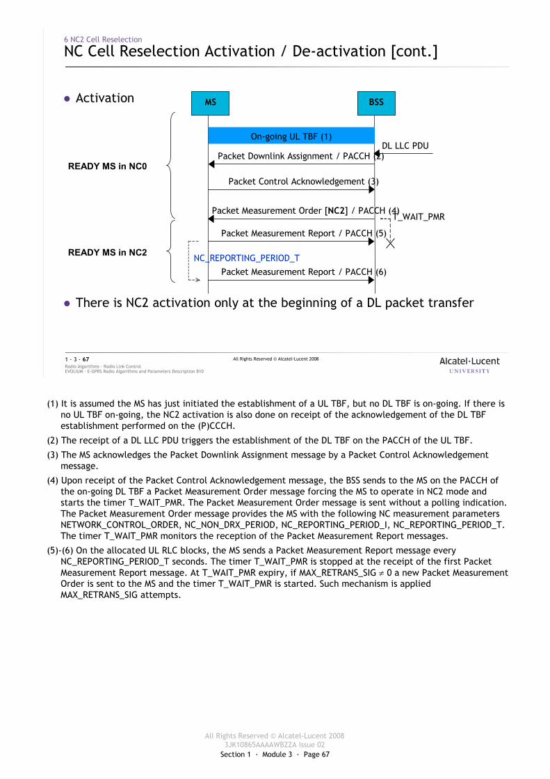
Section 1 · Module 3 · Page 67
All Rights Reserved © Alcatel-Lucent 20083JK10865AAAAWBZZA Issue 02
All Rights Reserved © Alcatel-Lucent 2008
EVOLIUM · E-GPRS Radio Algorithms and Parameters Description B10Radio Algorithms · Radio Link Control1 · 3 · 67
6 NC2 Cell Reselection
NC Cell Reselection Activation / De-activation [cont.]
� Activation
� There is NC2 activation only at the beginning of a DL packet transfer
T_WAIT_PMR
NC_REPORTING_PERIOD_T
MS BSS
Packet Measurement Order [NC2] / PACCH (4)
Packet Measurement Report / PACCH (5)
On-going UL TBF (1)
Packet Measurement Report / PACCH (6)
Packet Downlink Assignment / PACCH (2)
Packet Control Acknowledgement (3)
DL LLC PDU
READY MS in NC0
READY MS in NC2
(1) It is assumed the MS has just initiated the establishment of a UL TBF, but no DL TBF is on-going. If there is no UL TBF on-going, the NC2 activation is also done on receipt of the acknowledgement of the DL TBF establishment performed on the (P)CCCH.
(2) The receipt of a DL LLC PDU triggers the establishment of the DL TBF on the PACCH of the UL TBF.
(3) The MS acknowledges the Packet Downlink Assignment message by a Packet Control Acknowledgement message.
(4) Upon receipt of the Packet Control Acknowledgement message, the BSS sends to the MS on the PACCH of the on-going DL TBF a Packet Measurement Order message forcing the MS to operate in NC2 mode and starts the timer T_WAIT_PMR. The Packet Measurement Order message is sent without a polling indication. The Packet Measurement Order message provides the MS with the following NC measurement parameters NETWORK_CONTROL_ORDER, NC_NON_DRX_PERIOD, NC_REPORTING_PERIOD_I, NC_REPORTING_PERIOD_T. The timer T_WAIT_PMR monitors the reception of the Packet Measurement Report messages.
(5)-(6) On the allocated UL RLC blocks, the MS sends a Packet Measurement Report message every NC_REPORTING_PERIOD_T seconds. The timer T_WAIT_PMR is stopped at the receipt of the first Packet Measurement Report message. At T_WAIT_PMR expiry, if MAX_RETRANS_SIG ≠ 0 a new Packet Measurement Order is sent to the MS and the timer T_WAIT_PMR is started. Such mechanism is applied MAX_RETRANS_SIG attempts.
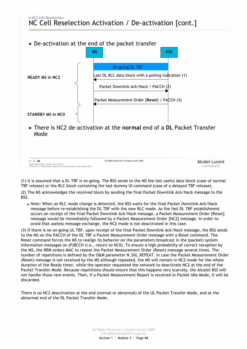
Section 1 · Module 3 · Page 68
All Rights Reserved © Alcatel-Lucent 20083JK10865AAAAWBZZA Issue 02
All Rights Reserved © Alcatel-Lucent 2008
EVOLIUM · E-GPRS Radio Algorithms and Parameters Description B10Radio Algorithms · Radio Link Control1 · 3 · 68
6 NC2 Cell Reselection
NC Cell Reselection Activation / De-activation [cont.]
� De-activation at the end of the packet transfer
� There is NC2 de-activation at the normal end of a DL Packet Transfer Mode
Packet Downlink Ack/Nack / PACCH (2)
Last DL RLC data block with a polling indication (1)
Packet Measurement Order [Reset] / PACCH (3)
MS BSS
On-going DL TBF
READY MS in NC2
STANDBY MS in NC0
(1) It is assumed that a DL TBF is on-going. The BSS sends to the MS the last useful data block (case of normal TBF release) or the RLC block containing the last dummy UI command (case of a delayed TBF release).
(2) The MS acknowledges the received block by sending the final Packet Downlink Ack/Nack message to the BSS.
� Note: When an RLC mode change is detected, the BSS waits for the final Packet Downlink Ack/Nack message before re-establishing the DL TBF with the new RLC mode. As the fast DL TBF establishment occurs on receipt of the final Packet Downlink Ack/Nack message, a Packet Measurement Order [Reset] message would be immediately followed by a Packet Measurement Order [NC2] message. In order to avoid that useless message exchange, the NC2 mode is not deactivated in this case.
(3) If there is no on-going UL TBF, upon receipt of the final Packet Downlink Ack/Nack message, the BSS sends to the MS on the PACCH of the DL TBF a Packet Measurement Order message with a Reset command. The Reset command forces the MS to realign its behavior on the parameters broadcast in the (packet) system information messages on (P)BCCH (i.e., return to NC0). To ensure a high probability of correct reception by the MS, the RRM orders MAC to repeat the Packet Measurement Order (Reset) message several times. The number of repetitions is defined by the O&M parameter N_SIG_REPEAT. In case the Packet Measurement Order (Reset) message is not received by the MS although repeated, the MS will remain in NC2 mode for the whole duration of the Ready timer, while the operator requested the network to deactivate NC2 at the end of the Packet Transfer Mode. Because repetitions should ensure that this happens very scarcely, the Alcatel BSS will not handle those rare events. Then, if a Packet Measurement Report is received in Packet Idle Mode, it will be discarded.
There is no NC2 deactivation at the end (normal or abnormal) of the UL Packet Transfer Mode, and at the abnormal end of the DL Packet Transfer Mode.
Section 1 · Module 3 · Page 69
All Rights Reserved © Alcatel-Lucent 20083JK10865AAAAWBZZA Issue 02
All Rights Reserved © Alcatel-Lucent 2008
EVOLIUM · E-GPRS Radio Algorithms and Parameters Description B10Radio Algorithms · Radio Link Control1 · 3 · 69
6 NC2 Cell Reselection
NC Measurement Reporting and Processing
� DL RXLEV� The MS sends a “Packet Measurement Report” message containing the RXLEV
measured on the serving cell and the 6 best neighbor cells
� The “Packet Measurement Report” message is sent every:� NC_REPORTING_PERIOD_T ms, in case of Packet Transfer Mode� NC_REPORTING_PERIOD_I ms, in case of Packet Idle Mode
On the one hand the NC_REPORTING_PERIOD_T parameter is defined by O&M on a per cell basis. On the other hand, the NC_REPORTING_PERIOD_I is set on a BSS cell basis without OMC-R access (default value = max value = 61.44 s i.e., 256 52-multiframes).
These parameters are provided to the MS either in a Packet Measurement Order message or in a Packet Cell Change Order message. They are never broadcast on (packet) system information messages.
Packet Measurement Report message contents
� TLLI of the MS
� NC_MODE (Set to NC2)
� RXLEV_SERVING_CELL (RXLEV measured on the serving cell)
� NUMBER_OF_NC_MEASUREMENTS (Number of measurements reported for the neighboring cells)
� FREQUENCY_N (Refer to the ARFCN or ARFCN and BSIC of a neighboring cell)
� BSIC (BSIC of the indexed neighboring cells)
� RXLEV_N (RXLEV of the indexed neighboring cells)
Section 1 · Module 3 · Page 70
All Rights Reserved © Alcatel-Lucent 20083JK10865AAAAWBZZA Issue 02
All Rights Reserved © Alcatel-Lucent 2008
EVOLIUM · E-GPRS Radio Algorithms and Parameters Description B10Radio Algorithms · Radio Link Control1 · 3 · 70
6 NC2 Cell Reselection
NC Measurement Reporting and Processing [cont.]
� DL RXLEV averaging for serving cell and neighbor cell� AV_DL_RXLEV_NC2p = (1-f)* AV_DL_RXLEV_NC2p-1 + f*RXLEV_Np
� RXLEV_Np is the RXLEV sample reported by the MS in the incoming Packet Measurement Report message
� f is the averaging forgetting factor and is derived from the parameter NC_RXLEV_FORGETTING_FACTOR
� p is the iteration index
NC_RXLEV_FORGETTING_FACTOR = 0.13 ((Alcatel recommended value) and it can be set at OMC-R level).
If the neighboring cell n was not reported in the precedent Packet Measurement Report but just in the last one:
� AV_DL_RXLEV_NC2p(n) = (1-f) *AV_DL_RXLEV_NC2p-1(n) + (1-(1-f) ) *RXLEV_Np(n)
� = (p –1) – i
� The index i represents the last time an NC measurement for that neighboring cell has been reported in a Packet Measurement Report message.
Section 1 · Module 3 · Page 71
All Rights Reserved © Alcatel-Lucent 20083JK10865AAAAWBZZA Issue 02
All Rights Reserved © Alcatel-Lucent 2008
EVOLIUM · E-GPRS Radio Algorithms and Parameters Description B10Radio Algorithms · Radio Link Control1 · 3 · 71
6 NC2 Cell Reselection
NC Measurement Reporting and Processing [cont.]
� RXQUAL for a GPRS TBF� In the DL, the MS sends a “Packet DL Ack/Nack” message containing the
RXQUAL measured on the serving cell every T_DL_GPRS_MeasReport ms� In the UL, the MFS assesses the RXQUAL for each RLC block received
� MeanBEP for an EGPRS TBF� In the DL, the MS sends an “EGPRS Packet DL Ack/Nack” message containing
the MeanBEP measured on the serving cell every T_DL_EGPRS_MeasReportms
� In the UL, the MFS assesses the MeanBEP for each RLC block received
T_DL_GPRS_MeasReport and T_DL_EGPRS_MeasReport are defined by O&M on a per cell basis.
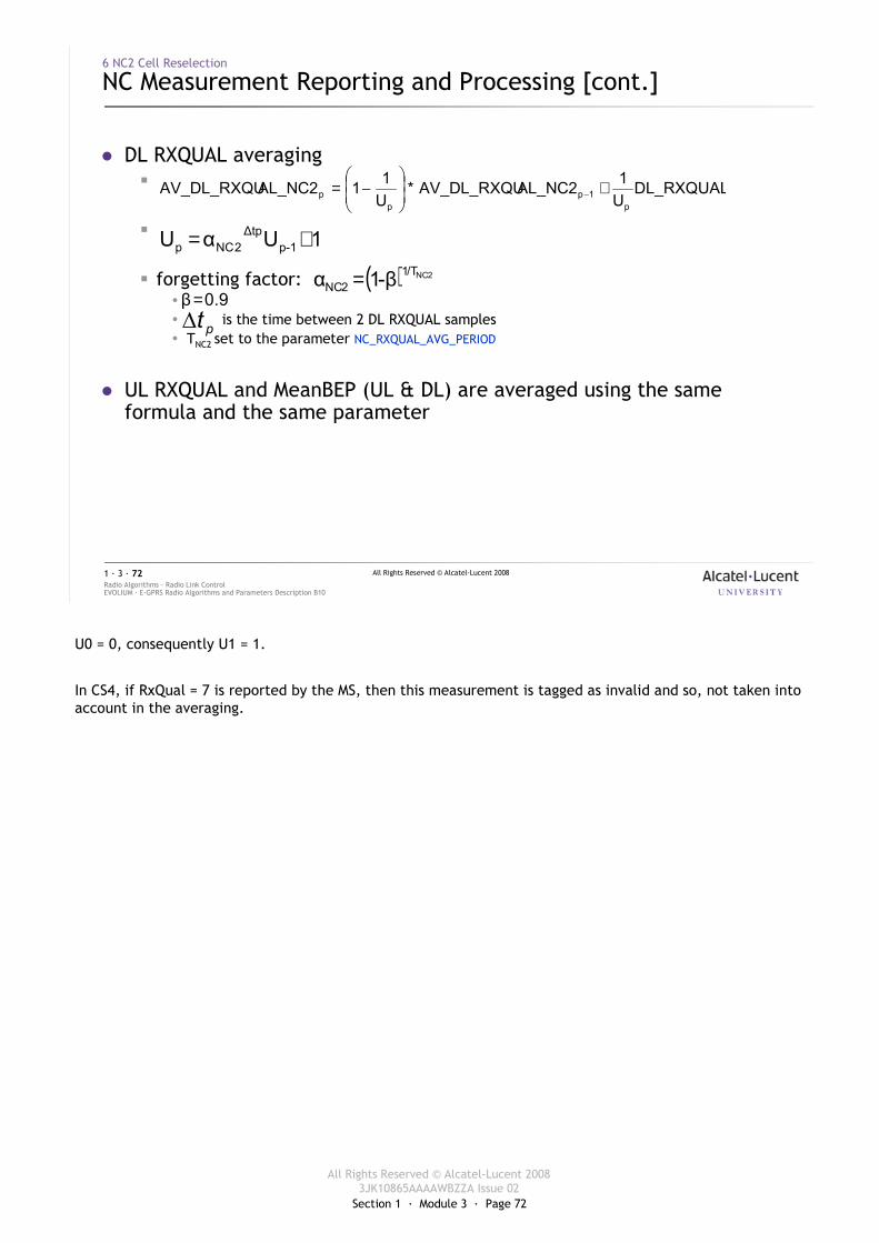
Section 1 · Module 3 · Page 72
All Rights Reserved © Alcatel-Lucent 20083JK10865AAAAWBZZA Issue 02
All Rights Reserved © Alcatel-Lucent 2008
EVOLIUM · E-GPRS Radio Algorithms and Parameters Description B10Radio Algorithms · Radio Link Control1 · 3 · 72
6 NC2 Cell Reselection
NC Measurement Reporting and Processing [cont.]
� DL RXQUAL averaging�
�
� forgetting factor:�� is the time between 2 DL RXQUAL samples� TNC2 set to the parameter NC_RXQUAL_AVG_PERIOD
� UL RXQUAL and MeanBEP (UL & DL) are averaged using the same formula and the same parameter
DL_RXQUALU12AL_NCAV_DL_RXQU*
U112AL_NCAV_DL_RXQU
p1p
pp +
−= −
1UαU 1p-∆tp
2NCp +=
( ) 2NC/T12NC β-1α =
0.9β=
pt∆
U0 = 0, consequently U1 = 1.
In CS4, if RxQual = 7 is reported by the MS, then this measurement is tagged as invalid and so, not taken into account in the averaging.
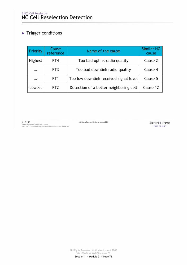
Section 1 · Module 3 · Page 73
All Rights Reserved © Alcatel-Lucent 20083JK10865AAAAWBZZA Issue 02
All Rights Reserved © Alcatel-Lucent 2008
EVOLIUM · E-GPRS Radio Algorithms and Parameters Description B10Radio Algorithms · Radio Link Control1 · 3 · 73
6 NC2 Cell Reselection
NC Cell Reselection Detection
� Trigger conditions
Detection of a better neighboring cell
Too low downlink received signal level
Too bad downlink radio quality
Too bad uplink radio quality
Name of the cause
Cause 12PT2Lowest
Cause 5PT1…
Cause 4PT3…
Cause 2PT4Highest
Similar HO cause
Cause referencePriority
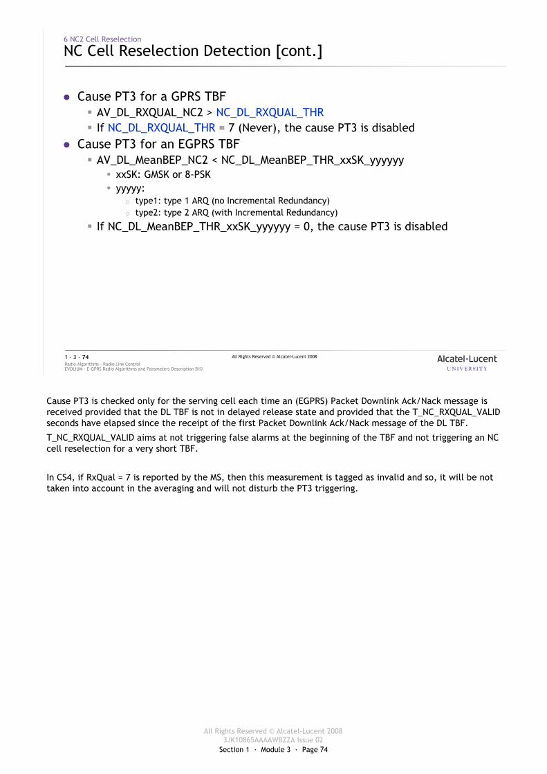
Section 1 · Module 3 · Page 74
All Rights Reserved © Alcatel-Lucent 20083JK10865AAAAWBZZA Issue 02
All Rights Reserved © Alcatel-Lucent 2008
EVOLIUM · E-GPRS Radio Algorithms and Parameters Description B10Radio Algorithms · Radio Link Control1 · 3 · 74
6 NC2 Cell Reselection
NC Cell Reselection Detection [cont.]
� Cause PT3 for a GPRS TBF� AV_DL_RXQUAL_NC2 > NC_DL_RXQUAL_THR� If NC_DL_RXQUAL_THR = 7 (Never), the cause PT3 is disabled
� Cause PT3 for an EGPRS TBF� AV_DL_MeanBEP_NC2 < NC_DL_MeanBEP_THR_xxSK_yyyyyy
� xxSK: GMSK or 8-PSK� yyyyy:
� type1: type 1 ARQ (no Incremental Redundancy)� type2: type 2 ARQ (with Incremental Redundancy)
� If NC_DL_MeanBEP_THR_xxSK_yyyyyy = 0, the cause PT3 is disabled
Cause PT3 is checked only for the serving cell each time an (EGPRS) Packet Downlink Ack/Nack message is received provided that the DL TBF is not in delayed release state and provided that the T_NC_RXQUAL_VALID seconds have elapsed since the receipt of the first Packet Downlink Ack/Nack message of the DL TBF.
T_NC_RXQUAL_VALID aims at not triggering false alarms at the beginning of the TBF and not triggering an NC cell reselection for a very short TBF.
In CS4, if RxQual = 7 is reported by the MS, then this measurement is tagged as invalid and so, it will be not taken into account in the averaging and will not disturb the PT3 triggering.
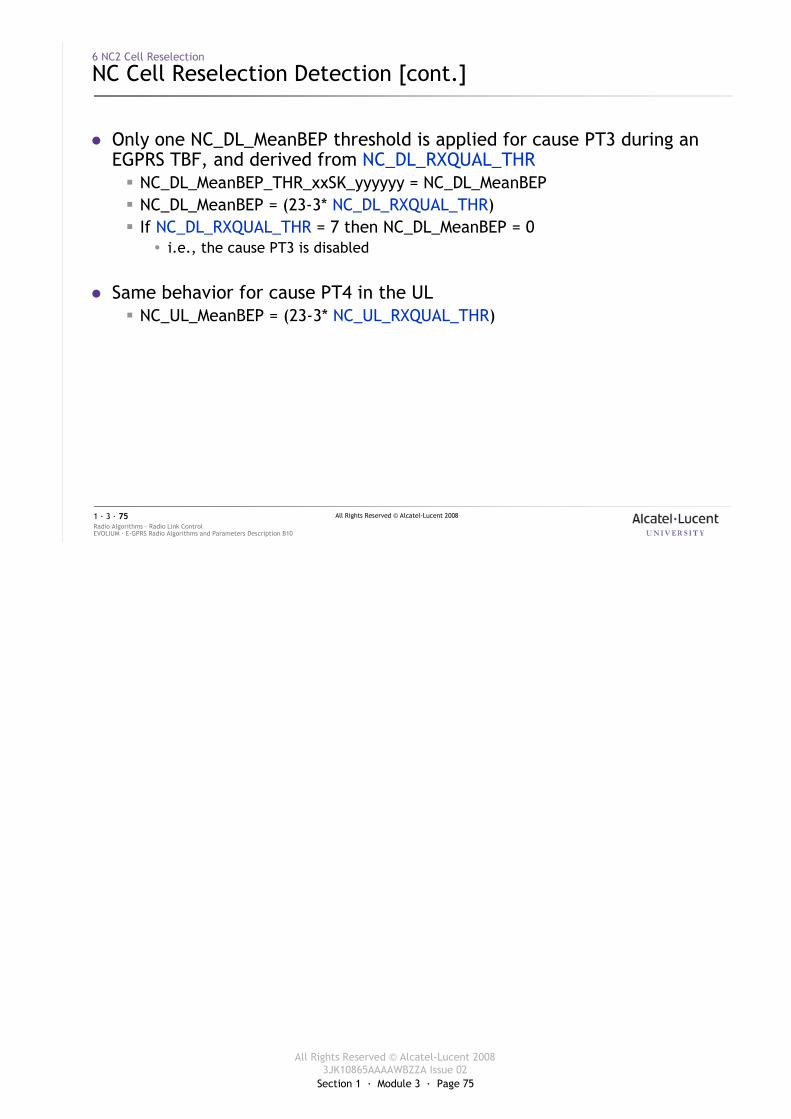
Section 1 · Module 3 · Page 75
All Rights Reserved © Alcatel-Lucent 20083JK10865AAAAWBZZA Issue 02
All Rights Reserved © Alcatel-Lucent 2008
EVOLIUM · E-GPRS Radio Algorithms and Parameters Description B10Radio Algorithms · Radio Link Control1 · 3 · 75
6 NC2 Cell Reselection
NC Cell Reselection Detection [cont.]
� Only one NC_DL_MeanBEP threshold is applied for cause PT3 during an EGPRS TBF, and derived from NC_DL_RXQUAL_THR� NC_DL_MeanBEP_THR_xxSK_yyyyyy = NC_DL_MeanBEP� NC_DL_MeanBEP = (23-3* NC_DL_RXQUAL_THR)� If NC_DL_RXQUAL_THR = 7 then NC_DL_MeanBEP = 0
� i.e., the cause PT3 is disabled
� Same behavior for cause PT4 in the UL� NC_UL_MeanBEP = (23-3* NC_UL_RXQUAL_THR)
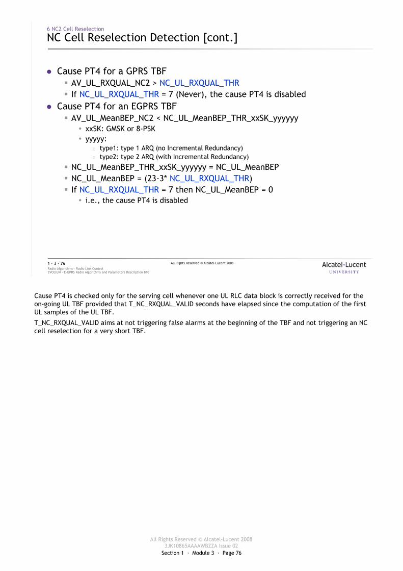
Section 1 · Module 3 · Page 76
All Rights Reserved © Alcatel-Lucent 20083JK10865AAAAWBZZA Issue 02
All Rights Reserved © Alcatel-Lucent 2008
EVOLIUM · E-GPRS Radio Algorithms and Parameters Description B10Radio Algorithms · Radio Link Control1 · 3 · 76
6 NC2 Cell Reselection
NC Cell Reselection Detection [cont.]
� Cause PT4 for a GPRS TBF� AV_UL_RXQUAL_NC2 > NC_UL_RXQUAL_THR� If NC_UL_RXQUAL_THR = 7 (Never), the cause PT4 is disabled
� Cause PT4 for an EGPRS TBF� AV_UL_MeanBEP_NC2 < NC_UL_MeanBEP_THR_xxSK_yyyyyy
� xxSK: GMSK or 8-PSK� yyyyy:
� type1: type 1 ARQ (no Incremental Redundancy)� type2: type 2 ARQ (with Incremental Redundancy)
� NC_UL_MeanBEP_THR_xxSK_yyyyyy = NC_UL_MeanBEP� NC_UL_MeanBEP = (23-3* NC_UL_RXQUAL_THR)� If NC_UL_RXQUAL_THR = 7 then NC_UL_MeanBEP = 0
� i.e., the cause PT4 is disabled
Cause PT4 is checked only for the serving cell whenever one UL RLC data block is correctly received for the on-going UL TBF provided that T_NC_RXQUAL_VALID seconds have elapsed since the computation of the first UL samples of the UL TBF.
T_NC_RXQUAL_VALID aims at not triggering false alarms at the beginning of the TBF and not triggering an NC cell reselection for a very short TBF.
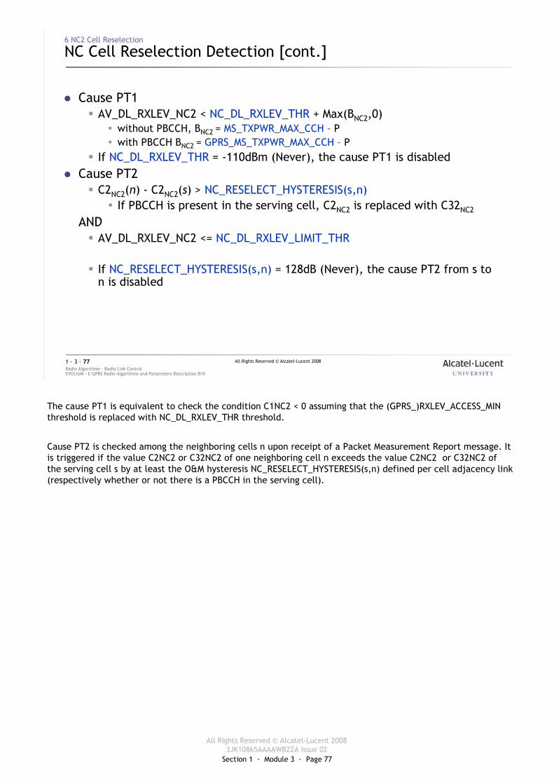
Section 1 · Module 3 · Page 77
All Rights Reserved © Alcatel-Lucent 20083JK10865AAAAWBZZA Issue 02
All Rights Reserved © Alcatel-Lucent 2008
EVOLIUM · E-GPRS Radio Algorithms and Parameters Description B10Radio Algorithms · Radio Link Control1 · 3 · 77
6 NC2 Cell Reselection
NC Cell Reselection Detection [cont.]
� Cause PT1� AV_DL_RXLEV_NC2 < NC_DL_RXLEV_THR + Max(BNC2,0)
� without PBCCH, BNC2 = MS_TXPWR_MAX_CCH – P� with PBCCH BNC2 = GPRS_MS_TXPWR_MAX_CCH – P
� If NC_DL_RXLEV_THR = -110dBm (Never), the cause PT1 is disabled� Cause PT2
� C2NC2(n) - C2NC2(s) > NC_RESELECT_HYSTERESIS(s,n)� If PBCCH is present in the serving cell, C2NC2 is replaced with C32NC2
AND� AV_DL_RXLEV_NC2 <= NC_DL_RXLEV_LIMIT_THR
� If NC_RESELECT_HYSTERESIS(s,n) = 128dB (Never), the cause PT2 from s to n is disabled
The cause PT1 is equivalent to check the condition C1NC2 < 0 assuming that the (GPRS_)RXLEV_ACCESS_MIN threshold is replaced with NC_DL_RXLEV_THR threshold.
Cause PT2 is checked among the neighboring cells n upon receipt of a Packet Measurement Report message. It is triggered if the value C2NC2 or C32NC2 of one neighboring cell n exceeds the value C2NC2 or C32NC2 of the serving cell s by at least the O&M hysteresis NC_RESELECT_HYSTERESIS(s,n) defined per cell adjacency link (respectively whether or not there is a PBCCH in the serving cell).
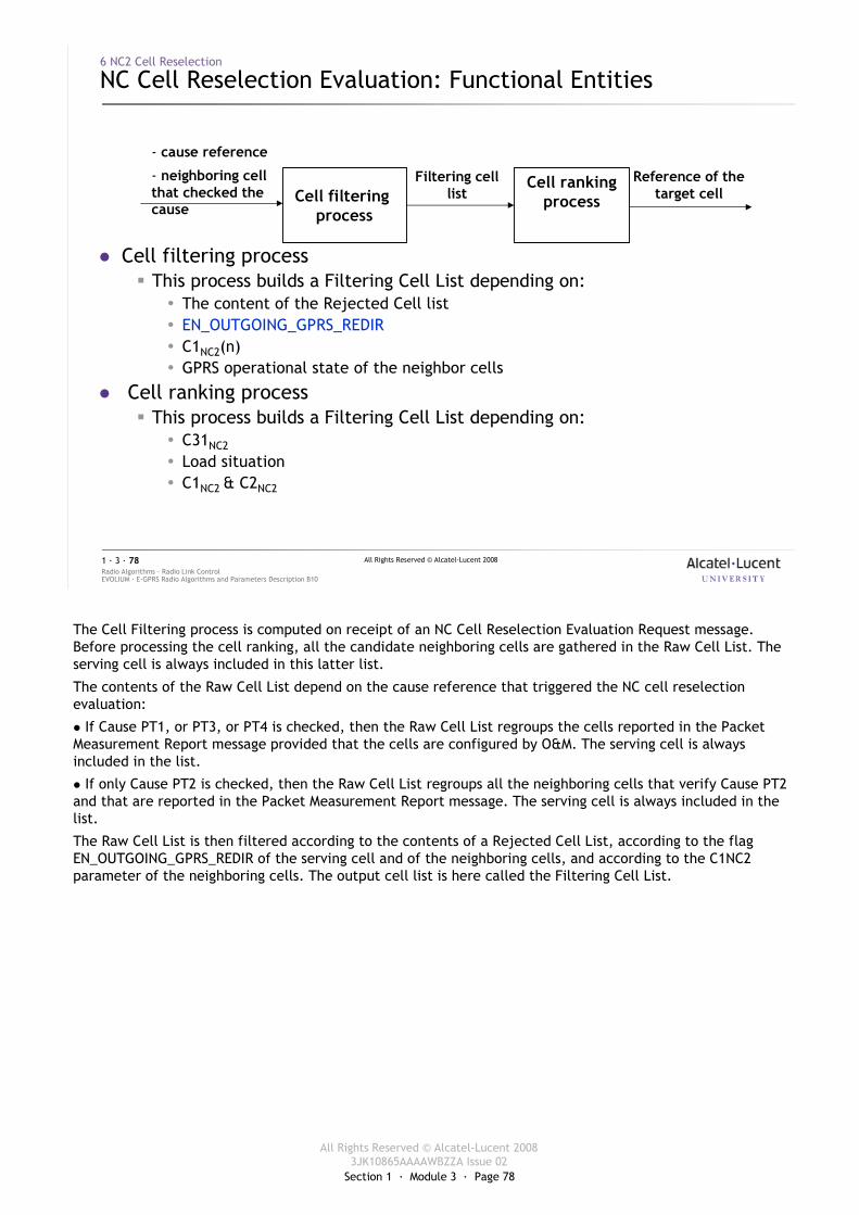
Section 1 · Module 3 · Page 78
All Rights Reserved © Alcatel-Lucent 20083JK10865AAAAWBZZA Issue 02
All Rights Reserved © Alcatel-Lucent 2008
EVOLIUM · E-GPRS Radio Algorithms and Parameters Description B10Radio Algorithms · Radio Link Control1 · 3 · 78
6 NC2 Cell Reselection
NC Cell Reselection Evaluation: Functional Entities
� Cell filtering process� This process builds a Filtering Cell List depending on:
� The content of the Rejected Cell list� EN_OUTGOING_GPRS_REDIR� C1NC2(n)� GPRS operational state of the neighbor cells
� Cell ranking process� This process builds a Filtering Cell List depending on:
� C31NC2
� Load situation� C1NC2 & C2NC2
Cell filtering process
Cell rankingprocess
- cause reference
- neighboring cell that checked the cause
Filtering cell list
Reference of the target cell
The Cell Filtering process is computed on receipt of an NC Cell Reselection Evaluation Request message. Before processing the cell ranking, all the candidate neighboring cells are gathered in the Raw Cell List. The serving cell is always included in this latter list.
The contents of the Raw Cell List depend on the cause reference that triggered the NC cell reselection evaluation:
� If Cause PT1, or PT3, or PT4 is checked, then the Raw Cell List regroups the cells reported in the Packet Measurement Report message provided that the cells are configured by O&M. The serving cell is always included in the list.
� If only Cause PT2 is checked, then the Raw Cell List regroups all the neighboring cells that verify Cause PT2 and that are reported in the Packet Measurement Report message. The serving cell is always included in the list.
The Raw Cell List is then filtered according to the contents of a Rejected Cell List, according to the flag EN_OUTGOING_GPRS_REDIR of the serving cell and of the neighboring cells, and according to the C1NC2 parameter of the neighboring cells. The output cell list is here called the Filtering Cell List.
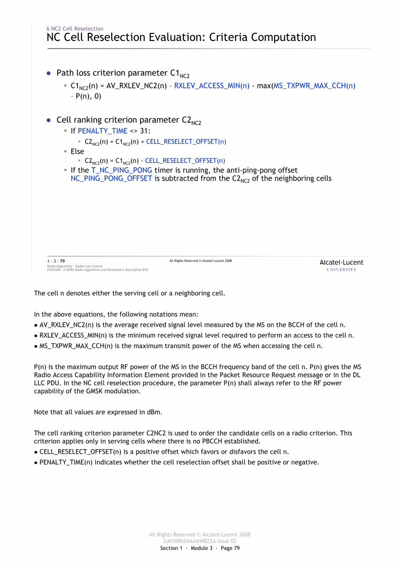
Section 1 · Module 3 · Page 79
All Rights Reserved © Alcatel-Lucent 20083JK10865AAAAWBZZA Issue 02
All Rights Reserved © Alcatel-Lucent 2008
EVOLIUM · E-GPRS Radio Algorithms and Parameters Description B10Radio Algorithms · Radio Link Control1 · 3 · 79
6 NC2 Cell Reselection
NC Cell Reselection Evaluation: Criteria Computation
� Path loss criterion parameter C1NC2
� C1NC2(n) = AV_RXLEV_NC2(n) – RXLEV_ACCESS_MIN(n) - max(MS_TXPWR_MAX_CCH(n)– P(n), 0)
� Cell ranking criterion parameter C2NC2� If PENALTY_TIME <> 31:
� C2NC2(n) = C1NC2(n) + CELL_RESELECT_OFFSET(n)
� Else� C2NC2(n) = C1NC2(n) - CELL_RESELECT_OFFSET(n)
� If the T_NC_PING_PONG timer is running, the anti-ping-pong offset NC_PING_PONG_OFFSET is subtracted from the C2NC2 of the neighboring cells
The cell n denotes either the serving cell or a neighboring cell.
In the above equations, the following notations mean:
� AV_RXLEV_NC2(n) is the average received signal level measured by the MS on the BCCH of the cell n.
� RXLEV_ACCESS_MIN(n) is the minimum received signal level required to perform an access to the cell n.
� MS_TXPWR_MAX_CCH(n) is the maximum transmit power of the MS when accessing the cell n.
P(n) is the maximum output RF power of the MS in the BCCH frequency band of the cell n. P(n) gives the MS Radio Access Capability Information Element provided in the Packet Resource Request message or in the DL LLC PDU. In the NC cell reselection procedure, the parameter P(n) shall always refer to the RF power capability of the GMSK modulation.
Note that all values are expressed in dBm.
The cell ranking criterion parameter C2NC2 is used to order the candidate cells on a radio criterion. This criterion applies only in serving cells where there is no PBCCH established.
� CELL_RESELECT_OFFSET(n) is a positive offset which favors or disfavors the cell n.
� PENALTY_TIME(n) indicates whether the cell reselection offset shall be positive or negative.
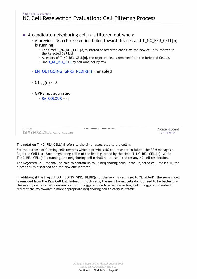
Section 1 · Module 3 · Page 80
All Rights Reserved © Alcatel-Lucent 20083JK10865AAAAWBZZA Issue 02
All Rights Reserved © Alcatel-Lucent 2008
EVOLIUM · E-GPRS Radio Algorithms and Parameters Description B10Radio Algorithms · Radio Link Control1 · 3 · 80
6 NC2 Cell Reselection
NC Cell Reselection Evaluation: Cell Filtering Process
� A candidate neighboring cell n is filtered out when:� A previous NC cell reselection failed toward this cell and T_NC_REJ_CELL[n]
is running� The timer T_NC_REJ_CELL[n] is started or restarted each time the new cell n is inserted in
the Rejected Cell List� At expiry of T_NC_REJ_CELL[n], the rejected cell is removed from the Rejected Cell List� One T_NC_REJ_CELL by cell (and not by MS)
� EN_OUTGOING_GPRS_REDIR(n) = enabled
� C1NC2(n) < 0
� GPRS not activated� RA_COLOUR = -1
The notation T_NC_REJ_CELL[n] refers to the timer associated to the cell n.
For the purpose of filtering cells towards which a previous NC cell reselection failed, the RRM manages a Rejected Cell List. Each neighboring cell n of the list is guarded by the timer T_NC_REJ_CELL[n]. While T_NC_REJ_CELL[n] is running, the neighboring cell n shall not be selected for any NC cell reselection.
The Rejected Cell List shall be able to contain up to 32 neighboring cells. If the Rejected cell List is full, the oldest cell is discarded and the new one is stored.
In addition, if the flag EN_OUT_GOING_GPRS_REDIR(s) of the serving cell is set to “Enabled”, the serving cell is removed from the Raw Cell List. Indeed, in such cells, the neighboring cells do not need to be better than the serving cell as a GPRS redirection is not triggered due to a bad radio link, but is triggered in order to redirect the MS towards a more appropriate neighboring cell to carry PS traffic.
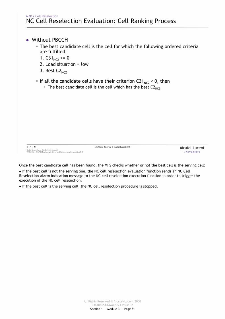
Section 1 · Module 3 · Page 81
All Rights Reserved © Alcatel-Lucent 20083JK10865AAAAWBZZA Issue 02
All Rights Reserved © Alcatel-Lucent 2008
EVOLIUM · E-GPRS Radio Algorithms and Parameters Description B10Radio Algorithms · Radio Link Control1 · 3 · 81
6 NC2 Cell Reselection
NC Cell Reselection Evaluation: Cell Ranking Process
� Without PBCCH� The best candidate cell is the cell for which the following ordered criteria
are fulfilled:1. C31NC2 >= 02. Load situation = low3. Best C2NC2
� If all the candidate cells have their criterion C31NC2 < 0, then� The best candidate cell is the cell which has the best C2NC2
Once the best candidate cell has been found, the MFS checks whether or not the best cell is the serving cell:
� If the best cell is not the serving one, the NC cell reselection evaluation function sends an NC Cell Reselection Alarm Indication message to the NC cell reselection execution function in order to trigger the execution of the NC cell reselection.
� If the best cell is the serving cell, the NC cell reselection procedure is stopped.
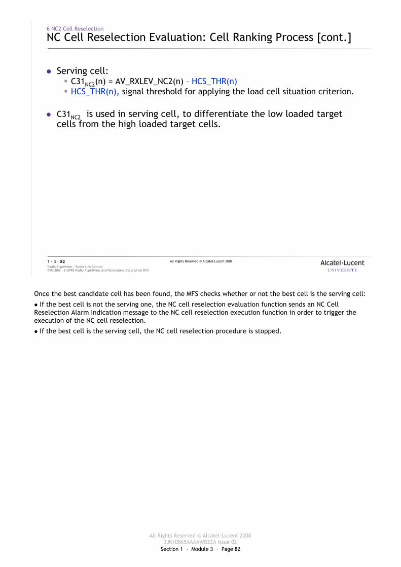
Section 1 · Module 3 · Page 82
All Rights Reserved © Alcatel-Lucent 20083JK10865AAAAWBZZA Issue 02
All Rights Reserved © Alcatel-Lucent 2008
EVOLIUM · E-GPRS Radio Algorithms and Parameters Description B10Radio Algorithms · Radio Link Control1 · 3 · 82
6 NC2 Cell Reselection
NC Cell Reselection Evaluation: Cell Ranking Process [cont.]
� Serving cell:� C31NC2(n) = AV_RXLEV_NC2(n) – HCS_THR(n)� HCS_THR(n), signal threshold for applying the load cell situation criterion.
� C31NC2 is used in serving cell, to differentiate the low loaded target cells from the high loaded target cells.
Once the best candidate cell has been found, the MFS checks whether or not the best cell is the serving cell:
� If the best cell is not the serving one, the NC cell reselection evaluation function sends an NC Cell Reselection Alarm Indication message to the NC cell reselection execution function in order to trigger the execution of the NC cell reselection.
� If the best cell is the serving cell, the NC cell reselection procedure is stopped.
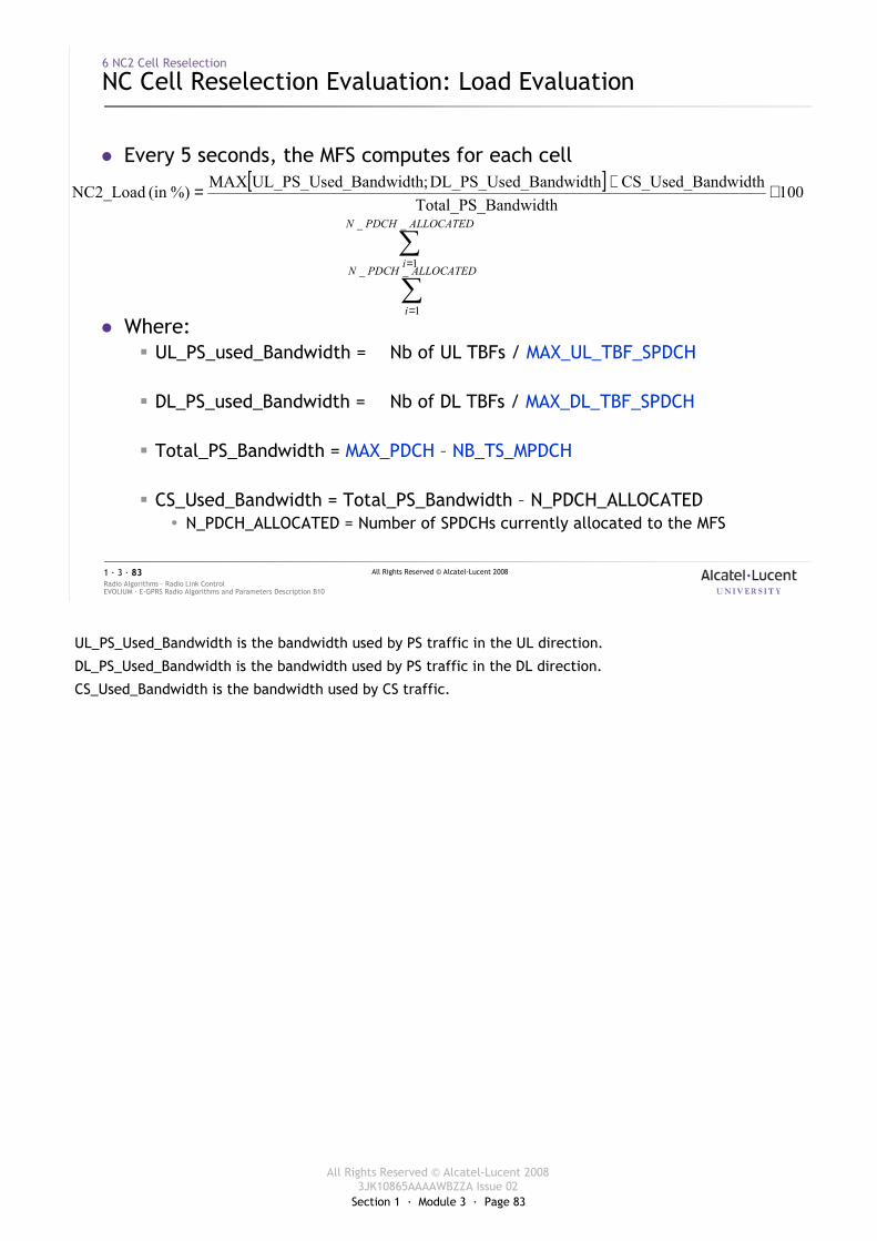
Section 1 · Module 3 · Page 83
All Rights Reserved © Alcatel-Lucent 20083JK10865AAAAWBZZA Issue 02
All Rights Reserved © Alcatel-Lucent 2008
EVOLIUM · E-GPRS Radio Algorithms and Parameters Description B10Radio Algorithms · Radio Link Control1 · 3 · 83
6 NC2 Cell Reselection
NC Cell Reselection Evaluation: Load Evaluation
� Every 5 seconds, the MFS computes for each cell
� Where:� UL_PS_used_Bandwidth = Nb of UL TBFs / MAX_UL_TBF_SPDCH
� DL_PS_used_Bandwidth = Nb of DL TBFs / MAX_DL_TBF_SPDCH
� Total_PS_Bandwidth = MAX_PDCH – NB_TS_MPDCH
� CS_Used_Bandwidth = Total_PS_Bandwidth – N_PDCH_ALLOCATED� N_PDCH_ALLOCATED = Number of SPDCHs currently allocated to the MFS
[ ] 100andwidthTotal_PS_B
ndwidthCS_Used_Ba_BandwidthDL_PS_Used;_BandwidthUL_PS_UsedMAX%)(in NC2_Load ×+=
∑=
ALLOCATEDPDCHN
i
__
1
∑=
ALLOCATEDPDCHN
i
__
1
UL_PS_Used_Bandwidth is the bandwidth used by PS traffic in the UL direction.
DL_PS_Used_Bandwidth is the bandwidth used by PS traffic in the DL direction.
CS_Used_Bandwidth is the bandwidth used by CS traffic.
Section 1 · Module 3 · Page 84
All Rights Reserved © Alcatel-Lucent 20083JK10865AAAAWBZZA Issue 02
All Rights Reserved © Alcatel-Lucent 2008
EVOLIUM · E-GPRS Radio Algorithms and Parameters Description B10Radio Algorithms · Radio Link Control1 · 3 · 84
6 NC2 Cell Reselection
NC Cell Reselection Evaluation: Load Evaluation [cont.]
� NC2_Load is averaged using the sliding window NC2_LOAD_EV_PERIOD(=3)
� This load average is then compared to the threshold THR_NC2_LOAD_RANKING as followed:� If Load average <= THR_NC2_LOAD_RANKING then
� Load situation = low� Else (Load average > THR_NC2_LOAD_RANKING)
� Load situation = high
� Case of the external cells (inter BSC)� If THR_NC2_LOAD_RANKING < 100% then Load situation = low� Else (THR_NC2_LOAD_RANKING = 100%) then Load situation = high
Exercise
The MFS shares the NC2 load situation information among the different cells of the BSS (or at least between the cells having a cell reselection link with the serving cell).
In case of an external cell, the load evaluation is different since the load situation of such cells is unknown in the serving cell.
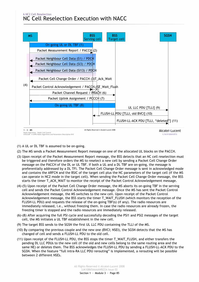
Section 1 · Module 3 · Page 85
All Rights Reserved © Alcatel-Lucent 20083JK10865AAAAWBZZA Issue 02
All Rights Reserved © Alcatel-Lucent 2008
EVOLIUM · E-GPRS Radio Algorithms and Parameters Description B10Radio Algorithms · Radio Link Control1 · 3 · 85
6 NC2 Cell Reselection
NC Cell Reselection Execution with NACC
T_Wait_Flush
T_Ack_Wait
On going UL TBF (8)
On going UL or DL TBF (1)
MS BSSServing cell
Packet Cell Change Order / PACCH (3)
Packet Measurement Report / PACCH (2)
BSSTarget cell
SGSN
Packet Control Acknowledgement / PACCH (5)(4)
Packet Channel Request / PRACH (6)
Packet Uplink Assignment / PCCCH (7)
UL LLC PDU [TLLI] (9)
FLUSH-LL PDU [TLLI, old BVCI] (10)
FLUSH-LL-ACK PDU [TLLI, “deleted”] (11)
Packet Neighbour Cell Data (SI3) / PDCH
Packet Neighbour Cell Data (S1) / PDCH
Packet Neighbour Cell Data (SI13) / PDCH
(1) A UL or DL TBF is assumed to be on-going.
(2) The MS sends a Packet Measurement Report message on one of the allocated UL blocks on the PACCH.
(3) Upon receipt of the Packet Measurement Report message, the BSS detects that an NC cell reselection must be triggered and therefore orders the MS to reselect a new cell by sending a Packet Cell Change Order message on the PACCH of the DL or UL TBF. If both a UL and a DL TBF are on-going, the message is preferentially addressed by a DL TFI. The Packet Cell Change Order message is sent in acknowledged mode and contains the ARFCN and the BSIC of the target cell plus the NC parameters of the target cell (if the MS can operate in NC2 mode in the target cell). When sending the Packet Cell Change Order message, the BSS starts the timer T_ACK_WAIT to monitor the receipt of the Packet Control Acknowledgement message.
(4)-(5) Upon receipt of the Packet Cell Change Order message, the MS aborts its on-going TBF in the serving cell and sends the Packet Control Acknowledgement message. Once the MS has sent the Packet Control Acknowledgement message, the MS switches to the new cell. Upon receipt of the Packet Control Acknowledgement message, the BSS starts the timer T_WAIT_FLUSH (which monitors the reception of the FLUSH-LL PDU) and requests the release of the on-going TBF(s) (if any). The radio resources are immediately released, i.e., without freezing them. In case the radio resources are already frozen, the freezing timer is stopped and the radio resources are immediately released.
(6)-(8) After acquiring the full PSI cycle and successfully decoding the PSI1 and PSI2 messages of the target cell, the MS initiates a UL TBF establishment in the new cell.
(9) The target BSS sends to the SGSN the first UL LLC PDU containing the TLLI of the MS.
(10) By comparing the previous couple and the new one (BVCI; NSEI), the SGSN detects that the MS has changed of cell and sends a FLUSH-LL PDU to the old cell.
(11) Upon receipt of the FLUSH-LL PDU, the BSS stops the timer T_WAIT_FLUSH, and either transfers the pending DL LLC PDUs to the new cell (if the old and new cells belong to the same routing area and the same NE) or deletes them. The BSS acknowledges the FLUSH-LL PDU by sending a FLUSH-LL-ACK PDU to the SGSN. When the feature “full intra-RA LLC PDU rerouting” is implemented, a rerouting will be possible between 2 different NSEs.
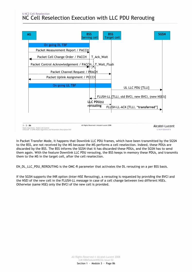
Section 1 · Module 3 · Page 86
All Rights Reserved © Alcatel-Lucent 20083JK10865AAAAWBZZA Issue 02
All Rights Reserved © Alcatel-Lucent 2008
EVOLIUM · E-GPRS Radio Algorithms and Parameters Description B10Radio Algorithms · Radio Link Control1 · 3 · 86
6 NC2 Cell Reselection
NC Cell Reselection Execution with LLC PDU Rerouting
T_Wait_Flush
T_Ack_Wait
On going UL TBF
On going DL TBF
MS BSSServing cell
Packet Cell Change Order / PACCH
Packet Measurement Report / PACCH
BSSTarget cell
SGSN
Packet Control Acknowledgement / PACCH
Packet Channel Request / PRACH
Packet Uplink Assignment / PCCCH
UL LLC PDU [TLLI]
FLUSH-LL [TLLI, old BVCI, new BVCI, (new NSEI)]
FLUSH-LL-ACK [TLLI, “transferred”]
LLC PDU(s) rerouting
In Packet Transfer Mode, it happens that Downlink LLC PDU frames, which have been transmitted by the SGSN to the BSS, are not received by the MS because the MS performs a cell reselection. Indeed, these PDUs are discarded by the BSS. The BSS informs the SGSN that it has discarded these PDUs, and the SGSN has to send them again. With the feature Downlink LLC PDU rerouting, the BSS keeps in memory these PDUs, and transmits them to the MS in the target cell, after the cell reselection.
EN_DL_LLC_PDU_REROUTING is the OMC-R parameter that activates the DL rerouting on a per BSS basis.
If the SGSN supports the INR option (Inter-NSE Rerouting), a rerouting is requested by providing the BVCI and the NSEI of the new cell in the FLUSH-LL message in case of a cell change between two different NSEs. Otherwise (same NSE) only the BVCI of the new cell is provided.
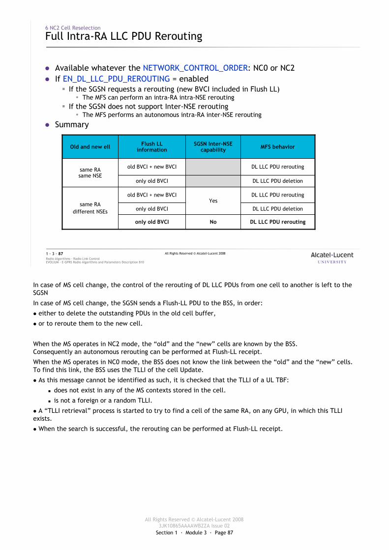
Section 1 · Module 3 · Page 87
All Rights Reserved © Alcatel-Lucent 20083JK10865AAAAWBZZA Issue 02
All Rights Reserved © Alcatel-Lucent 2008
EVOLIUM · E-GPRS Radio Algorithms and Parameters Description B10Radio Algorithms · Radio Link Control1 · 3 · 87
6 NC2 Cell Reselection
Full Intra-RA LLC PDU Rerouting
� Available whatever the NETWORK_CONTROL_ORDER: NC0 or NC2� If EN_DL_LLC_PDU_REROUTING = enabled
� If the SGSN requests a rerouting (new BVCI included in Flush LL)� The MFS can perform an intra-RA intra-NSE rerouting
� If the SGSN does not support Inter-NSE rerouting� The MFS performs an autonomous intra-RA inter-NSE rerouting
� Summary
DL LLC PDU reroutingNoonly old BVCI
DL LLC PDU deletiononly old BVCI
DL LLC PDU reroutingYes
old BVCI + new BVCI
same RAdifferent NSEs
DL LLC PDU deletiononly old BVCI
DL LLC PDU reroutingold BVCI + new BVCIsame RAsame NSE
MFS behaviorSGSN Inter-NSEcapability
Flush LLinformationOld and new ell
In case of MS cell change, the control of the rerouting of DL LLC PDUs from one cell to another is left to the SGSN
In case of MS cell change, the SGSN sends a Flush-LL PDU to the BSS, in order:
� either to delete the outstanding PDUs in the old cell buffer,
� or to reroute them to the new cell.
When the MS operates in NC2 mode, the “old” and the “new” cells are known by the BSS.Consequently an autonomous rerouting can be performed at Flush-LL receipt.
When the MS operates in NC0 mode, the BSS does not know the link between the “old” and the “new” cells. To find this link, the BSS uses the TLLI of the cell Update.
� As this message cannot be identified as such, it is checked that the TLLI of a UL TBF:
� does not exist in any of the MS contexts stored in the cell.
� is not a foreign or a random TLLI.
� A “TLLI retrieval” process is started to try to find a cell of the same RA, on any GPU, in which this TLLI exists.
� When the search is successful, the rerouting can be performed at Flush-LL receipt.
Section 1 · Module 3 · Page 88
All Rights Reserved © Alcatel-Lucent 20083JK10865AAAAWBZZA Issue 02
All Rights Reserved © Alcatel-Lucent 2008
EVOLIUM · E-GPRS Radio Algorithms and Parameters Description B10Radio Algorithms · Radio Link Control1 · 3 · 88
� Useful in multilayer and multiband networks, in order to reduce the number of reselections
� If EN_OUTGOING_GPRS_REDIR(s) = enabled� As soon as the MS is in Packet Transfer Mode, it is redirected from the cell� Then, the cell ranking process is started to find the best candidate cell
� According to the operator strategy� See session 4 for a strategy example
6 NC2 Cell Reselection
Outgoing GPRS Redirection
Exercise
An outgoing GPRS redirection is an NC cell reselection which is triggered when the MS enters the packet transfer mode in the serving cell even if the radio link is good.
The intention of GPRS redirections is to redirect the MS towards a target cell more appropriate to carry PS traffic (for instance a macro cell).

Section 1 · Module 3 · Page 89
All Rights Reserved © Alcatel-Lucent 20083JK10865AAAAWBZZA Issue 02
All Rights Reserved © Alcatel-Lucent 2008
EVOLIUM · E-GPRS Radio Algorithms and Parameters Description B10Radio Algorithms · Radio Link Control1 · 3 · 89
7 Flow Control at the Gb Interface
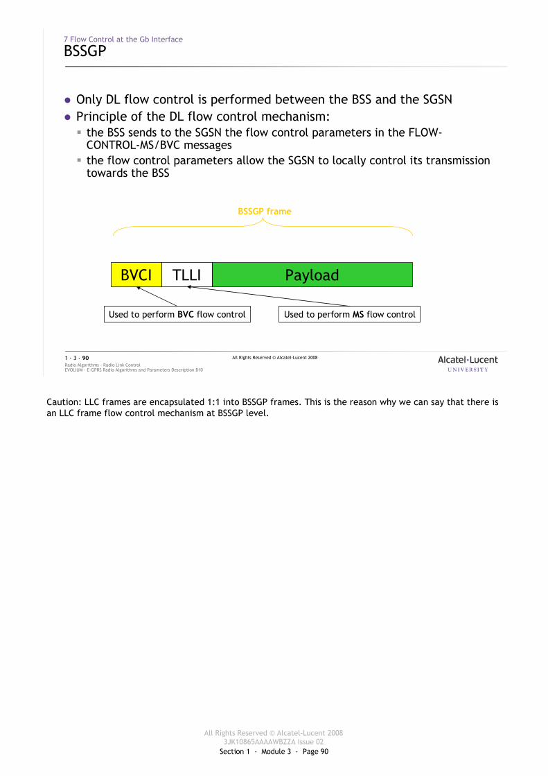
Section 1 · Module 3 · Page 90
All Rights Reserved © Alcatel-Lucent 20083JK10865AAAAWBZZA Issue 02
All Rights Reserved © Alcatel-Lucent 2008
EVOLIUM · E-GPRS Radio Algorithms and Parameters Description B10Radio Algorithms · Radio Link Control1 · 3 · 90
7 Flow Control at the Gb Interface
BSSGP
� Only DL flow control is performed between the BSS and the SGSN� Principle of the DL flow control mechanism:
� the BSS sends to the SGSN the flow control parameters in the FLOW-CONTROL-MS/BVC messages
� the flow control parameters allow the SGSN to locally control its transmission towards the BSS
PayloadTLLIBVCI
LLC frame
BSSGP frame
Used to perform MS flow controlUsed to perform BVC flow control
Caution: LLC frames are encapsulated 1:1 into BSSGP frames. This is the reason why we can say that there is an LLC frame flow control mechanism at BSSGP level.
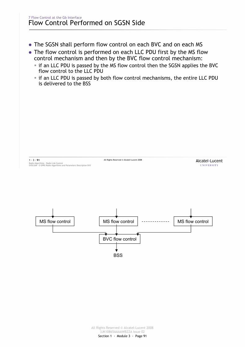
Section 1 · Module 3 · Page 91
All Rights Reserved © Alcatel-Lucent 20083JK10865AAAAWBZZA Issue 02
All Rights Reserved © Alcatel-Lucent 2008
EVOLIUM · E-GPRS Radio Algorithms and Parameters Description B10Radio Algorithms · Radio Link Control1 · 3 · 91
7 Flow Control at the Gb Interface
Flow Control Performed on SGSN Side
� The SGSN shall perform flow control on each BVC and on each MS� The flow control is performed on each LLC PDU first by the MS flow
control mechanism and then by the BVC flow control mechanism:� if an LLC PDU is passed by the MS flow control then the SGSN applies the BVC
flow control to the LLC PDU� if an LLC PDU is passed by both flow control mechanisms, the entire LLC PDU
is delivered to the BSS
MS flow control MS flow control MS flow control
BVC flow control
BSS
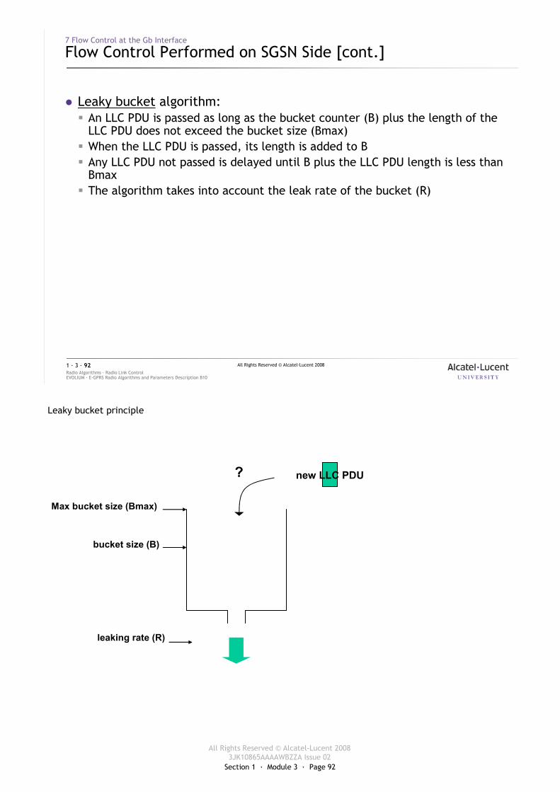
Section 1 · Module 3 · Page 92
All Rights Reserved © Alcatel-Lucent 20083JK10865AAAAWBZZA Issue 02
All Rights Reserved © Alcatel-Lucent 2008
EVOLIUM · E-GPRS Radio Algorithms and Parameters Description B10Radio Algorithms · Radio Link Control1 · 3 · 92
7 Flow Control at the Gb Interface
Flow Control Performed on SGSN Side [cont.]
� Leaky bucket algorithm:� An LLC PDU is passed as long as the bucket counter (B) plus the length of the
LLC PDU does not exceed the bucket size (Bmax)� When the LLC PDU is passed, its length is added to B� Any LLC PDU not passed is delayed until B plus the LLC PDU length is less than
Bmax� The algorithm takes into account the leak rate of the bucket (R)
Leaky bucket principle
bucket size (B)
Max bucket size (Bmax)
leaking rate (R)
new LLC PDU?
Section 1 · Module 3 · Page 93
All Rights Reserved © Alcatel-Lucent 20083JK10865AAAAWBZZA Issue 02
All Rights Reserved © Alcatel-Lucent 2008
EVOLIUM · E-GPRS Radio Algorithms and Parameters Description B10Radio Algorithms · Radio Link Control1 · 3 · 93
7 Flow Control at the Gb Interface
Flow Control Performed on BSS Side
� The BSS controls the DL transmission of the SGSN by sending the parameters Bmax and R in the flow control PDU:� after the sending of a FLOW_CONTROL_BVC PDU, the BSS cannot send a new
FLOW_CONTROL_BVC PDU before T_Flow_Ctrl_Cell seconds� T_Flow_Ctrl_Cell is a BSS parameter� Default value = 0� By default, the BVC flow control is disabled
� after the sending of a FLOW_CONTROL_MS PDU, the BSS cannot send a new FLOW_CONTROL_MS PDU before T_Flow_Ctrl_MS seconds� T_Flow_Ctrl_MS is a BSS parameter� Default value = 10 s
NB: the cell flow control is performed more frequently than the MS flow control because:
� The radio resource availability for a TBF is always shorter than the guarding time of a PDCH, therefore the MS individual traffic is less of an influence on the leaking rate.
� The radio resource available for one MS may change from one TBF to another.
� The combined traffic of all the GPRS MSs in the cell exchanging data with the SGSN has to be mapped onto a BVC, which may become the blocking factor as the BVC is mapped on an NSVC, which is mapped on a PVC, carried by a BC which has a fixed maximum capacity.
Section 1 · Module 3 · Page 94
All Rights Reserved © Alcatel-Lucent 20083JK10865AAAAWBZZA Issue 02
All Rights Reserved © Alcatel-Lucent 2008
EVOLIUM · E-GPRS Radio Algorithms and Parameters Description B10Radio Algorithms · Radio Link Control1 · 3 · 94
7 Flow Control at the Gb Interface
Flow Control Performed on BSS Side [cont.]
� FLOW_CONTROL_BVC PDU:� BVC_Bucket_Size: the maximum size of the cell buffer in the MFS� BVC_Bucket_Leak_Rate: the measured throughput in the cell from the RRM to
the RLC� Bmax_default_MS: the default value of the maximum size of the MS buffer in
the MFS� R_default_MS: the default value of the measured throughput for the MS from
the RRM to the RLC
Formulas:
�The BVC_Bucket_Size (value expressed in octet) is calculated as follows:
� Case T_Flow_Ctrl_Cell ≠ 0:
� BVC_Bucket_Size = Flow_Dim_safety_MS * Max_PDCH * Max_Rate_PDCH * (1/8) * Max_Rate_Safety * T_Flow_Ctrl_Cell
� Case T_Flow_Ctrl_Cell = 0:
� BVC_Bucket_Size = Flow_Dim_safety_MS * Max_PDCH * Max_Rate_PDCH * (1/8) * Max_Rate_Safety * Def_value_T_Flow_Ctrl_Cell
�The BVC_Bucket_Leak_Rate (value expressed in 100 bits/sec) is calculated as follows:
� Case T_Flow_Ctrl_Cell ≠ 0:
� IF B_BVC < BVC_Bucket_Size
BVC_Bucket_Leak_Rate = [(BVC_Bucket_Size - B_BVC )*8] / [T_Flow_Ctrl_Cell * Flow_Dim_safety_BVC * 100]
� ELSE
BVC_Bucket_Leak_Rate = 0
� Case T_Flow_Ctrl_Cell = 0
� BVC_Bucket_Leak_Rate = (Max_PDCH * Max_Rate_PDCH * Max_Rate_Safety)/100
�The Bmax_default_MS (value expressed in octet) is calculated as follows:
� Case T_Flow_Ctrl_MS ≠ 0:
� Bmax_default_MS = Flow_Dim_safety_MS * Max_Rate_PDCH * (1/8) * Max_Rate_Safety * T_Flow_Ctrl_MS
� Case T_Flow_Ctrl_MS = 0:
� Bmax_default_MS = Flow_Dim_safety_MS * Max_Rate_PDCH * (1/8) * Max_Rate_Safety * Def_value_T_Flow_Ctrl_MS
�The R_default_MS (value expressed in 100 bits/sec) is calculated as follows:
� R_default_MS = (Flow_Dim_safety_MS * Max_Rate_PDCH * Max_Rate_Safety)/100
Section 1 · Module 3 · Page 95
All Rights Reserved © Alcatel-Lucent 20083JK10865AAAAWBZZA Issue 02
All Rights Reserved © Alcatel-Lucent 2008
EVOLIUM · E-GPRS Radio Algorithms and Parameters Description B10Radio Algorithms · Radio Link Control1 · 3 · 95
7 Flow Control at the Gb Interface
Flow Control Performed on BSS Side [cont.]
� FLOW_CONTROL_MS PDU:� MS_Bucket_Size: the maximum size of the MS buffer in the MFS� MS_Bucket_Leak_Rate: the measured throughput for the MS from the RRM to
the RLC
Formula:
� The MS_Bucket_Size (value expressed in octet) is calculated as follows:
� MS_Bucket_Size = n * Max_Rate_PDCH * (1/8) * Max_Rate_Safety * T_Flow_Ctrl_MS
� The MS_Bucket_Leak_Rate (value expressed in 100 bit/sec) is calculated as follows:
� MS_Bucket_Leak_Rate = B_MS * 100 / MS_Bucket_Size
Explanation:
� Max_PDCH
� O&M parameter indicating the maximum number of PDCHs that can be established in the cell.
� Max_Rate_PDCH
� maximum rate of one PDCH in the considered cell (value in bits/s)
� Max_Rate_Safety
� Safety factor to compensate the Max_Rate_PDCH in the calculation of BVC_Bucket_Size and MS_Bucket_Size
� Flow_Dim_safety_BVC
� O&M safety factor, used to tune the BVC bucket value
� Flow_Dim_safety_MS
� O&M safety factor, used to tune the MS bucket value
� MAX_LLC_PDU
� maximum length of a DL LLC PDU (the SGSN has to be able to send at least one DL LLC PDU)
� B_BVC
� value in octet of the current bucket size at MFS side for the cell. It corresponds to the amount of LLC waiting frames for this BVC (cell)
� T_Flow_Ctrl_Cell
� sending period of NM-FLOW-CONTROL-CELL-req
� T_Flow_Ctrl_MS
� sending period of NM-FLOW-CONTROL-MS-req
� Def_value_T_Flow_Ctrl_Cell
� default value forT_Flow_Ctrl_Cell (set to 5 sec)
� Def_value_T_Flow_Ctrl_MS
� default value for T_Flow_Ctrl_MS (set to 10 sec)
� B_MS
� Value in octets of the current bucket size at MFS side for the MS. It corresponds to the amount of LLC PDUs waiting to be transmitted for this MS.
� n
� Maximum number of PDCHs that can be allocated to the MS according to its multislot class.

Section 1 · Module 3 · Page 96
All Rights Reserved © Alcatel-Lucent 20083JK10865AAAAWBZZA Issue 02
All Rights Reserved © Alcatel-Lucent 2008
EVOLIUM · E-GPRS Radio Algorithms and Parameters Description B10Radio Algorithms · Radio Link Control1 · 3 · 96
8 Radio Link Supervision
Section 1 · Module 3 · Page 97
All Rights Reserved © Alcatel-Lucent 20083JK10865AAAAWBZZA Issue 02
All Rights Reserved © Alcatel-Lucent 2008
EVOLIUM · E-GPRS Radio Algorithms and Parameters Description B10Radio Algorithms · Radio Link Control1 · 3 · 97
8 Radio Link Supervision
Principles
� During a UL or DL packet transmission, the corresponding TBF can be released due to an abnormal situation:� no acknowledgement or data received� the transmission is stalled� too low transmission efficiency
� The abnormal release is always followed by the re-establishment of the TBF in case of an uplink transfer (initiative of the MS)
� In case of a downlink transfer, most of the SGSNs do not take the initiative to re-establish the TBF
The RLS mechanisms processes in the MFS are based on the following assumption:
« in a specific transfer situation, the MFS is expecting the MS to behave in a specific way »:
� In a UL TBF, the MFS schedules a USF for UL blocks and expects the MS to understand the MFS’sacknowledgements.
� In a DL TBF, the MFS sends blocks to the MS and expects them to be acknowledged when scheduled by the MFS (use of RRBP).
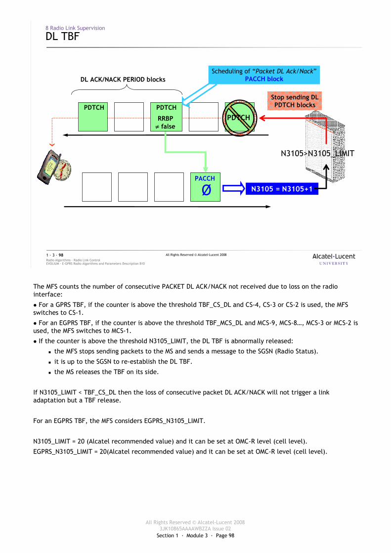
Section 1 · Module 3 · Page 98
All Rights Reserved © Alcatel-Lucent 20083JK10865AAAAWBZZA Issue 02
All Rights Reserved © Alcatel-Lucent 2008
EVOLIUM · E-GPRS Radio Algorithms and Parameters Description B10Radio Algorithms · Radio Link Control1 · 3 · 98
8 Radio Link Supervision
DL TBF
DL ACK/NACK PERIOD blocks
RRBP≠ false
Ø N3105 = N3105+1
PDTCH PDTCH
PACCH
Scheduling of “Packet DL Ack/Nack”PACCH block
N3105>N3105_LIMIT
PDTCH
Stop sending DLPDTCH blocks
The MFS counts the number of consecutive PACKET DL ACK/NACK not received due to loss on the radio interface:
� For a GPRS TBF, if the counter is above the threshold TBF_CS_DL and CS-4, CS-3 or CS-2 is used, the MFS switches to CS-1.
� For an EGPRS TBF, if the counter is above the threshold TBF_MCS_DL and MCS-9, MCS-8…, MCS-3 or MCS-2 is used, the MFS switches to MCS-1.
� If the counter is above the threshold N3105_LIMIT, the DL TBF is abnormally released:
� the MFS stops sending packets to the MS and sends a message to the SGSN (Radio Status).
� it is up to the SGSN to re-establish the DL TBF.
� the MS releases the TBF on its side.
If N3105_LIMIT < TBF_CS_DL then the loss of consecutive packet DL ACK/NACK will not trigger a link adaptation but a TBF release.
For an EGPRS TBF, the MFS considers EGPRS_N3105_LIMIT.
N3105_LIMIT = 20 (Alcatel recommended value) and it can be set at OMC-R level (cell level).
EGPRS_N3105_LIMIT = 20(Alcatel recommended value) and it can be set at OMC-R level (cell level).
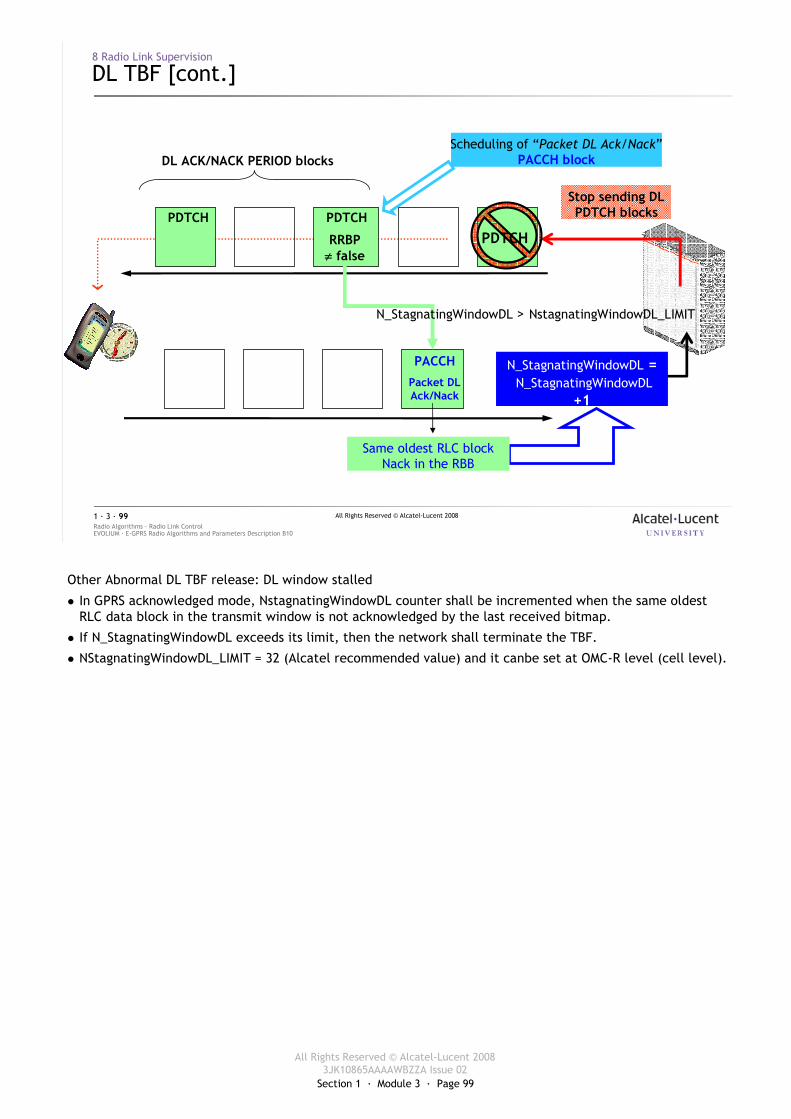
Section 1 · Module 3 · Page 99
All Rights Reserved © Alcatel-Lucent 20083JK10865AAAAWBZZA Issue 02
All Rights Reserved © Alcatel-Lucent 2008
EVOLIUM · E-GPRS Radio Algorithms and Parameters Description B10Radio Algorithms · Radio Link Control1 · 3 · 99
8 Radio Link Supervision
DL TBF [cont.]
DL ACK/NACK PERIOD blocks
RRBP≠ false
PDTCH PDTCH
PACCH
Packet DL Ack/Nack
Scheduling of “Packet DL Ack/Nack”PACCH block
PDTCH
Stop sending DLPDTCH blocks
N_StagnatingWindowDL =N_StagnatingWindowDL
+1
N_StagnatingWindowDL > NstagnatingWindowDL_LIMIT
Same oldest RLC block Nack in the RBB
Other Abnormal DL TBF release: DL window stalled
� In GPRS acknowledged mode, NstagnatingWindowDL counter shall be incremented when the same oldest RLC data block in the transmit window is not acknowledged by the last received bitmap.
� If N_StagnatingWindowDL exceeds its limit, then the network shall terminate the TBF.
� NStagnatingWindowDL_LIMIT = 32 (Alcatel recommended value) and it canbe set at OMC-R level (cell level).
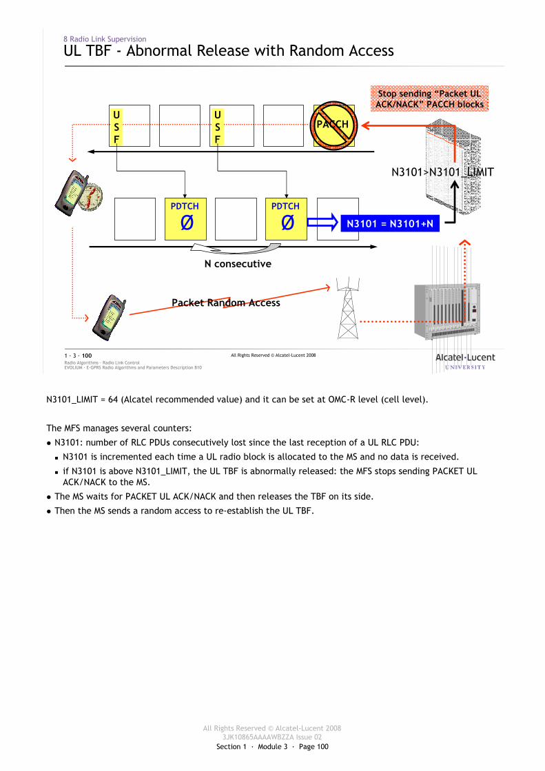
Section 1 · Module 3 · Page 100
All Rights Reserved © Alcatel-Lucent 20083JK10865AAAAWBZZA Issue 02
All Rights Reserved © Alcatel-Lucent 2008
EVOLIUM · E-GPRS Radio Algorithms and Parameters Description B10Radio Algorithms · Radio Link Control1 · 3 · 100
8 Radio Link Supervision
UL TBF - Abnormal Release with Random Access
N3101 = N3101+NØPDTCH
N3101>N3101_LIMIT
PACCH
Stop sending “Packet ULACK/NACK” PACCH blocks
ØPDTCH
N consecutive
USF
USF
Packet Random Access
N3101_LIMIT = 64 (Alcatel recommended value) and it can be set at OMC-R level (cell level).
The MFS manages several counters:
� N3101: number of RLC PDUs consecutively lost since the last reception of a UL RLC PDU:
� N3101 is incremented each time a UL radio block is allocated to the MS and no data is received.
� if N3101 is above N3101_LIMIT, the UL TBF is abnormally released: the MFS stops sending PACKET UL ACK/NACK to the MS.
� The MS waits for PACKET UL ACK/NACK and then releases the TBF on its side.
� Then the MS sends a random access to re-establish the UL TBF.
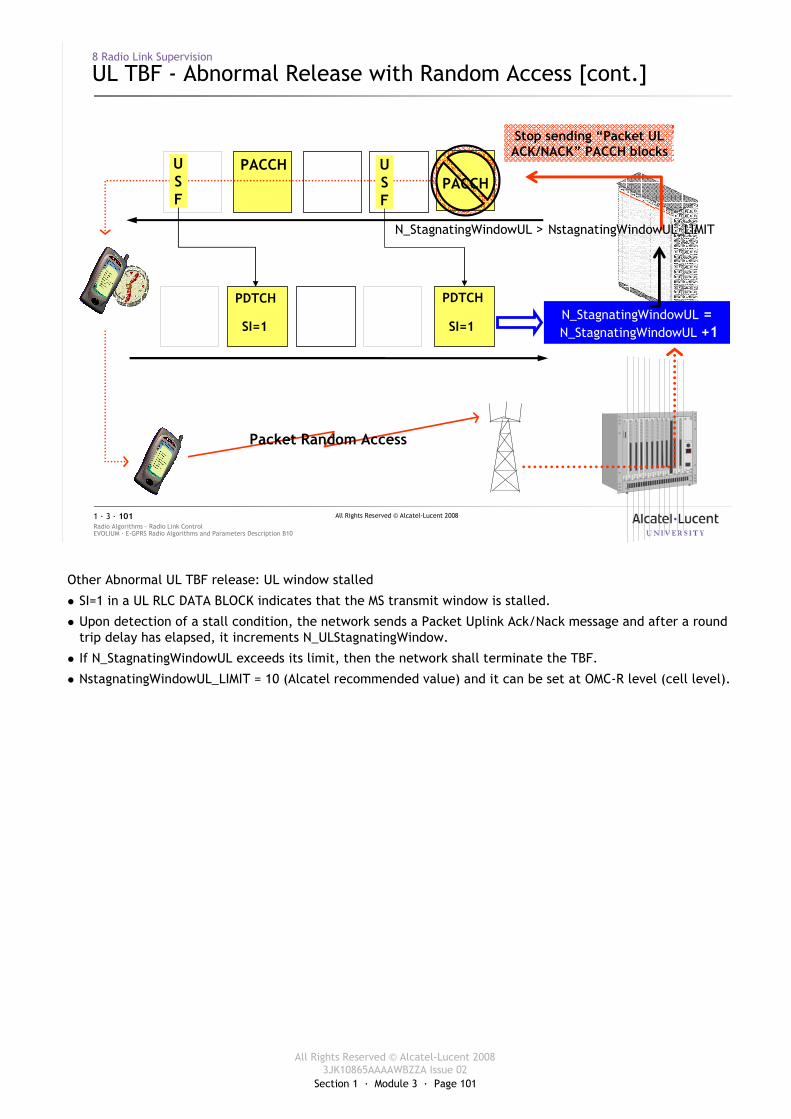
Section 1 · Module 3 · Page 101
All Rights Reserved © Alcatel-Lucent 20083JK10865AAAAWBZZA Issue 02
All Rights Reserved © Alcatel-Lucent 2008
EVOLIUM · E-GPRS Radio Algorithms and Parameters Description B10Radio Algorithms · Radio Link Control1 · 3 · 101
8 Radio Link Supervision
UL TBF - Abnormal Release with Random Access [cont.]
SI=1
PDTCHN_StagnatingWindowUL =N_StagnatingWindowUL +1
PACCH
Stop sending “Packet ULACK/NACK” PACCH blocks
SI=1
PDTCH
USF
USF
Packet Random Access
PACCH
N_StagnatingWindowUL > NstagnatingWindowUL_LIMIT
Other Abnormal UL TBF release: UL window stalled
� SI=1 in a UL RLC DATA BLOCK indicates that the MS transmit window is stalled.
� Upon detection of a stall condition, the network sends a Packet Uplink Ack/Nack message and after a round trip delay has elapsed, it increments N_ULStagnatingWindow.
� If N_StagnatingWindowUL exceeds its limit, then the network shall terminate the TBF.
� NstagnatingWindowUL_LIMIT = 10 (Alcatel recommended value) and it can be set at OMC-R level (cell level).
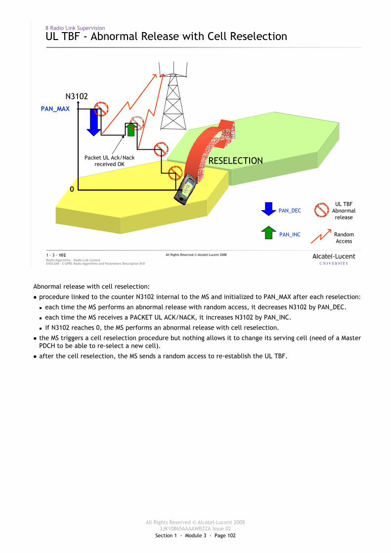
Section 1 · Module 3 · Page 102
All Rights Reserved © Alcatel-Lucent 20083JK10865AAAAWBZZA Issue 02
All Rights Reserved © Alcatel-Lucent 2008
EVOLIUM · E-GPRS Radio Algorithms and Parameters Description B10Radio Algorithms · Radio Link Control1 · 3 · 102
8 Radio Link Supervision
UL TBF - Abnormal Release with Cell Reselection
RESELECTION
N3102PAN_MAX
0
UL TBFAbnormalrelease
RandomAccess
PAN_DEC
PAN_INC
Packet UL Ack/Nackreceived OK
Abnormal release with cell reselection:
� procedure linked to the counter N3102 internal to the MS and initialized to PAN_MAX after each reselection:
� each time the MS performs an abnormal release with random access, it decreases N3102 by PAN_DEC.
� each time the MS receives a PACKET UL ACK/NACK, it increases N3102 by PAN_INC.
� if N3102 reaches 0, the MS performs an abnormal release with cell reselection.
� the MS triggers a cell reselection procedure but nothing allows it to change its serving cell (need of a Master PDCH to be able to re-select a new cell).
� after the cell reselection, the MS sends a random access to re-establish the UL TBF.
Section 1 · Module 3 · Page 103
All Rights Reserved © Alcatel-Lucent 20083JK10865AAAAWBZZA Issue 02
All Rights Reserved © Alcatel-Lucent 2008
EVOLIUM · E-GPRS Radio Algorithms and Parameters Description B10Radio Algorithms · Radio Link Control1 · 3 · 103
8 Radio Link Supervision
UL TBF - Abnormal Release with Cell Reselection [cont.]
� If a Master PDCH is available in the serving cell AND� If RANDOM_ACC_RETRY = Allowed
� Then the following reselection algorithm is applied:� The MS re-selects the cell with the highest RLA among the 6 best levels� In this cell, if the MS cannot decode the PBCCH data block, it reselects the next
highest Received Level Average� If the cells with the 6 strongest RLAs have been tried but cannot be used, the MS
performs a normal reselection (see 5 NC0 Cell Selection and Reselection)� Else the normal reselection algorithm is applied (see 4)
� After T_RESEL, the MS is allowed to reselect the serving cell
RLA = Received Level Average.
T_RESEL = 5s (default value).
Extract of the 05.08 GSM standard:
In the event of an abnormal release with cell reselection (see 3GPP TS 04.60) when PBCCH exists, an abnormal cell reselection based on BA(GPRS) shall be attempted. The MS shall perform the following algorithm to determine which cell to be used for this cell reselection attempt.
If access to another cell is not allowed, i.e., RANDOM_ACCESS_RETRY bit is not set on the serving cell:
� i) The abnormal cell reselection attempt shall be abandoned.
If access to another cell is allowed, i.e., RANDOM_ACCESS_RETRY bit is set on the serving cell:
� i) The received level measurement samples taken on the carriers indicated in the BA (GPRS) received on the serving cell in the last 5 seconds shall be averaged, and the carrier with the highest Received Level Average (RLA) with permitted BSIC, i.e., the same as broadcast together with BA (GPRS), shall be taken.
� ii) On this carrier, the MS shall attempt to decode the PBCCH data block containing the parameters affecting cell selection.
� iii) If the cell is suitable (see 3GPP TS 022), abnormal cell reselection shall be attempted on this cell.
� iv) If the MS is unable to decode the PBCCH data block or if the conditions in iii) are not met, the carrier with the next highest Received Level Average (RLA) with permitted BSIC shall be taken, and the MS shall repeat steps ii) and iii) above.
� v) If the cells with the 6 strongest Received Level Average (RLA) values with permitted BSICs have been tried but cannot be used, the abnormal cell reselection attempt shall be abandoned.
The MS is under no circumstances allowed to access a cell to attempt abnormal cell reselection later than 20 seconds after the detection within the MS of the abnormal release causing the abnormal cell reselection attempt. In the case where the 20 seconds elapse without a successful abnormal cell reselection, the attempt shall be abandoned.
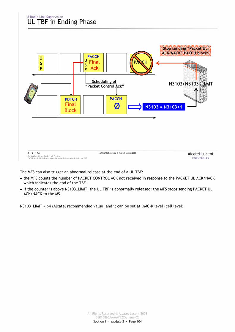
Section 1 · Module 3 · Page 104
All Rights Reserved © Alcatel-Lucent 20083JK10865AAAAWBZZA Issue 02
All Rights Reserved © Alcatel-Lucent 2008
EVOLIUM · E-GPRS Radio Algorithms and Parameters Description B10Radio Algorithms · Radio Link Control1 · 3 · 104
8 Radio Link Supervision
UL TBF in Ending Phase
N3103 = N3103+1ØPACCH
N3103>N3103_LIMIT
PACCH
Stop sending “Packet ULACK/NACK” PACCH blocks
FinalBlock
PDTCH
USF
USF
PACCHFinalAck
Scheduling of “Packet Control Ack”
The MFS can also trigger an abnormal release at the end of a UL TBF:
� the MFS counts the number of PACKET CONTROL ACK not received in response to the PACKET UL ACK/NACK which indicates the end of the TBF.
� if the counter is above N3103_LIMIT, the UL TBF is abnormally released: the MFS stops sending PACKET UL ACK/NACK to the MS.
N3103_LIMIT = 64 (Alcatel recommended value) and it can be set at OMC-R level (cell level).
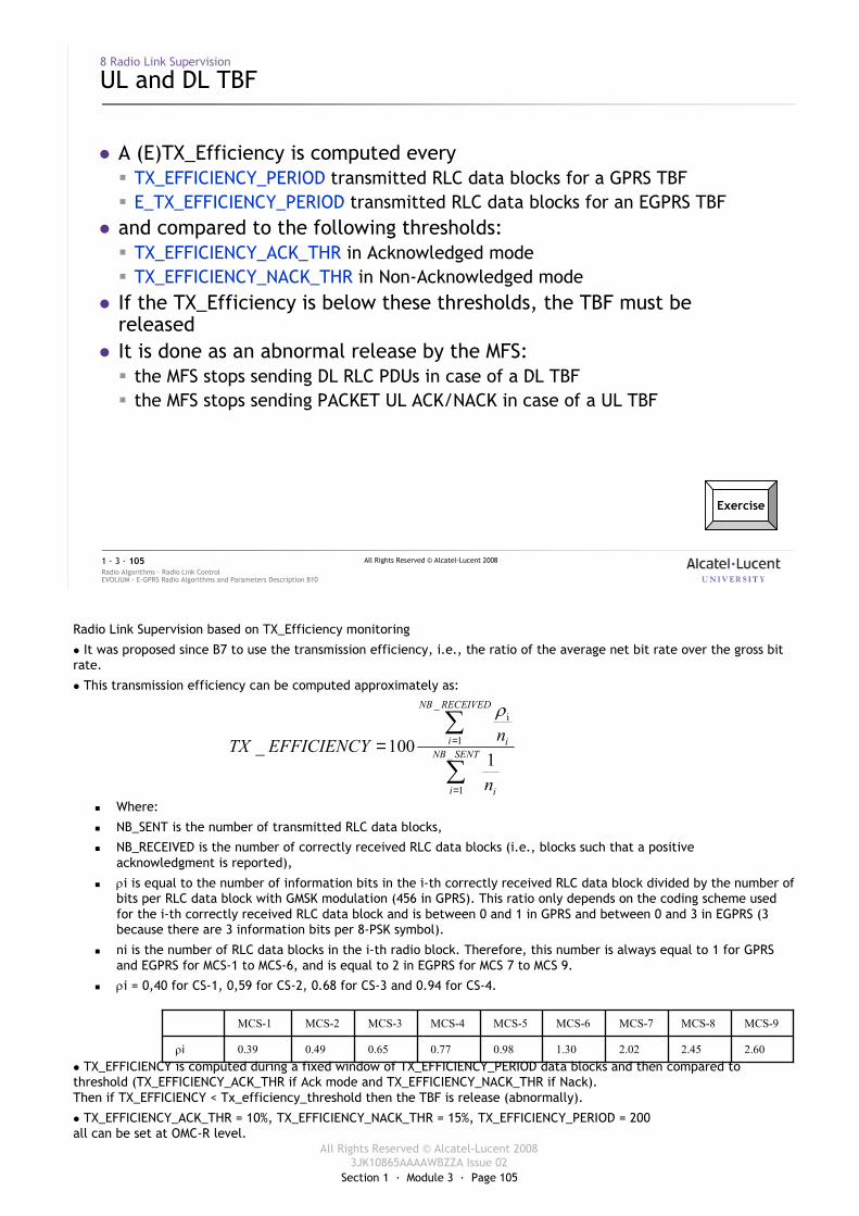
Section 1 · Module 3 · Page 105
All Rights Reserved © Alcatel-Lucent 20083JK10865AAAAWBZZA Issue 02
All Rights Reserved © Alcatel-Lucent 2008
EVOLIUM · E-GPRS Radio Algorithms and Parameters Description B10Radio Algorithms · Radio Link Control1 · 3 · 105
8 Radio Link Supervision
UL and DL TBF
� A (E)TX_Efficiency is computed every � TX_EFFICIENCY_PERIOD transmitted RLC data blocks for a GPRS TBF� E_TX_EFFICIENCY_PERIOD transmitted RLC data blocks for an EGPRS TBF
� and compared to the following thresholds:� TX_EFFICIENCY_ACK_THR in Acknowledged mode� TX_EFFICIENCY_NACK_THR in Non-Acknowledged mode
� If the TX_Efficiency is below these thresholds, the TBF must be released
� It is done as an abnormal release by the MFS:� the MFS stops sending DL RLC PDUs in case of a DL TBF� the MFS stops sending PACKET UL ACK/NACK in case of a UL TBF
Exercise
Radio Link Supervision based on TX_Efficiency monitoring
� It was proposed since B7 to use the transmission efficiency, i.e., the ratio of the average net bit rate over the gross bit rate.
� This transmission efficiency can be computed approximately as:
� Where:
� NB_SENT is the number of transmitted RLC data blocks,
� NB_RECEIVED is the number of correctly received RLC data blocks (i.e., blocks such that a positive acknowledgment is reported),
� ρi is equal to the number of information bits in the i-th correctly received RLC data block divided by the number of bits per RLC data block with GMSK modulation (456 in GPRS). This ratio only depends on the coding scheme used for the i-th correctly received RLC data block and is between 0 and 1 in GPRS and between 0 and 3 in EGPRS (3 because there are 3 information bits per 8-PSK symbol).
� ni is the number of RLC data blocks in the i-th radio block. Therefore, this number is always equal to 1 for GPRS and EGPRS for MCS-1 to MCS-6, and is equal to 2 in EGPRS for MCS 7 to MCS 9.
� ρi = 0,40 for CS-1, 0,59 for CS-2, 0.68 for CS-3 and 0.94 for CS-4.
� TX_EFFICIENCY is computed during a fixed window of TX_EFFICIENCY_PERIOD data blocks and then compared to threshold (TX_EFFICIENCY_ACK_THR if Ack mode and TX_EFFICIENCY_NACK_THR if Nack).Then if TX_EFFICIENCY < Tx_efficiency_threshold then the TBF is release (abnormally).
� TX_EFFICIENCY_ACK_THR = 10%, TX_EFFICIENCY_NACK_THR = 15%, TX_EFFICIENCY_PERIOD = 200all can be set at OMC-R level.
∑
∑
=
== SENTNB
i i
RECEIVEDNB
i i
n
nEFFICIENCYTX _
1
_
1
i
1100_
ρ
2.602.452.021.300.980.770.650.490.39ρi
MCS-9MCS-8MCS-7MCS-6MCS-5MCS-4MCS-3MCS-2MCS-1
Section 1 · Module 3 · Page 106
All Rights Reserved © Alcatel-Lucent 20083JK10865AAAAWBZZA Issue 02
All Rights Reserved © Alcatel-Lucent 2008
EVOLIUM · E-GPRS Radio Algorithms and Parameters Description B10Radio Algorithms · Radio Link Control1 · 3 · 106
9 Exercises
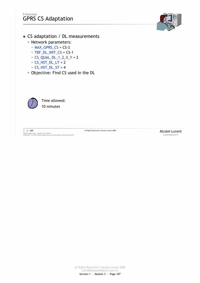
Section 1 · Module 3 · Page 107
All Rights Reserved © Alcatel-Lucent 20083JK10865AAAAWBZZA Issue 02
All Rights Reserved © Alcatel-Lucent 2008
EVOLIUM · E-GPRS Radio Algorithms and Parameters Description B10Radio Algorithms · Radio Link Control1 · 3 · 107
9 Exercises
GPRS CS Adaptation
� CS adaptation / DL measurements� Network parameters:� MAX_GPRS_CS = CS-2� TBF_DL_INIT_CS = CS-1� CS_QUAL_DL_1_2_X_Y = 2� CS_HST_DL_LT = 2� CS_HST_DL_ST = 4
� Objective: Find CS used in the DL
Time allowed:
10 minutes
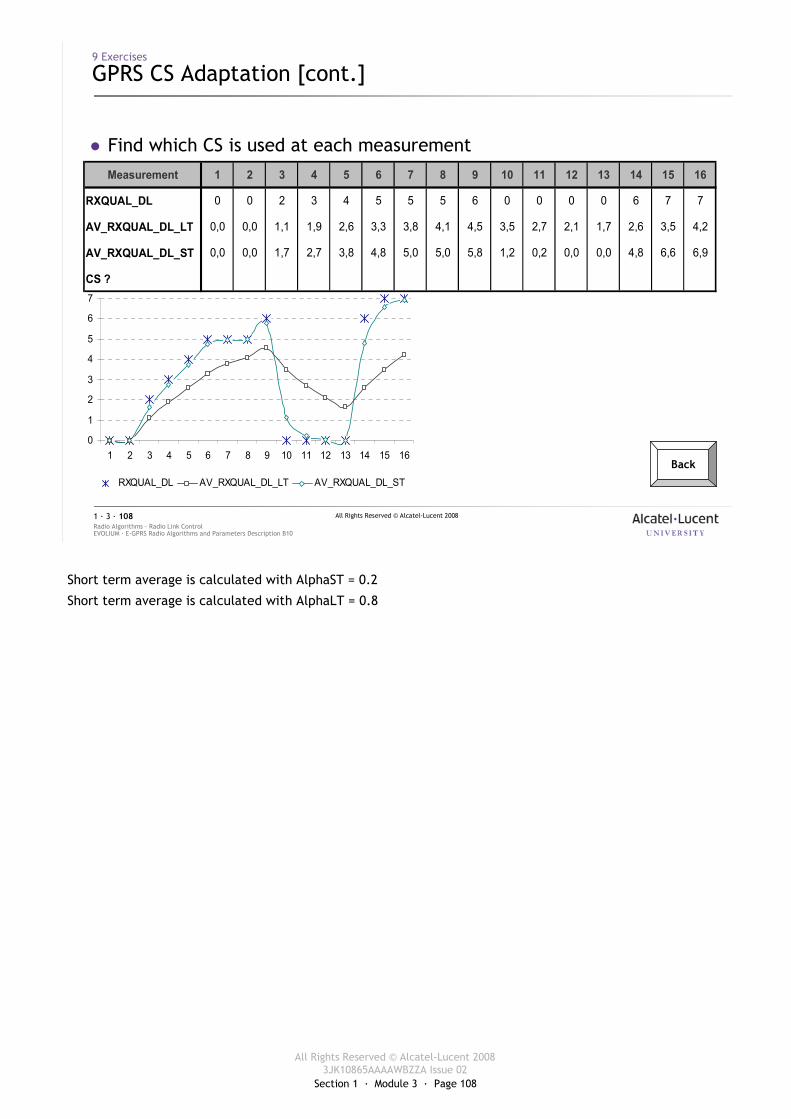
Section 1 · Module 3 · Page 108
All Rights Reserved © Alcatel-Lucent 20083JK10865AAAAWBZZA Issue 02
All Rights Reserved © Alcatel-Lucent 2008
EVOLIUM · E-GPRS Radio Algorithms and Parameters Description B10Radio Algorithms · Radio Link Control1 · 3 · 108
9 Exercises
GPRS CS Adaptation [cont.]
� Find which CS is used at each measurementMeasurement 1 2 3 4 5 6 7 8 9 10 11 12 13 14 15 16
RXQUAL_DL 0 0 2 3 4 5 5 5 6 0 0 0 0 6 7 7
AV_RXQUAL_DL_LT 0,0 0,0 1,1 1,9 2,6 3,3 3,8 4,1 4,5 3,5 2,7 2,1 1,7 2,6 3,5 4,2
AV_RXQUAL_DL_ST 0,0 0,0 1,7 2,7 3,8 4,8 5,0 5,0 5,8 1,2 0,2 0,0 0,0 4,8 6,6 6,9
CS ?
0
1
2
3
4
5
6
7
1 2 3 4 5 6 7 8 9 10 11 12 13 14 15 16
RXQUAL_DL AV_RXQUAL_DL_LT AV_RXQUAL_DL_ST
Back
Short term average is calculated with AlphaST = 0.2
Short term average is calculated with AlphaLT = 0.8
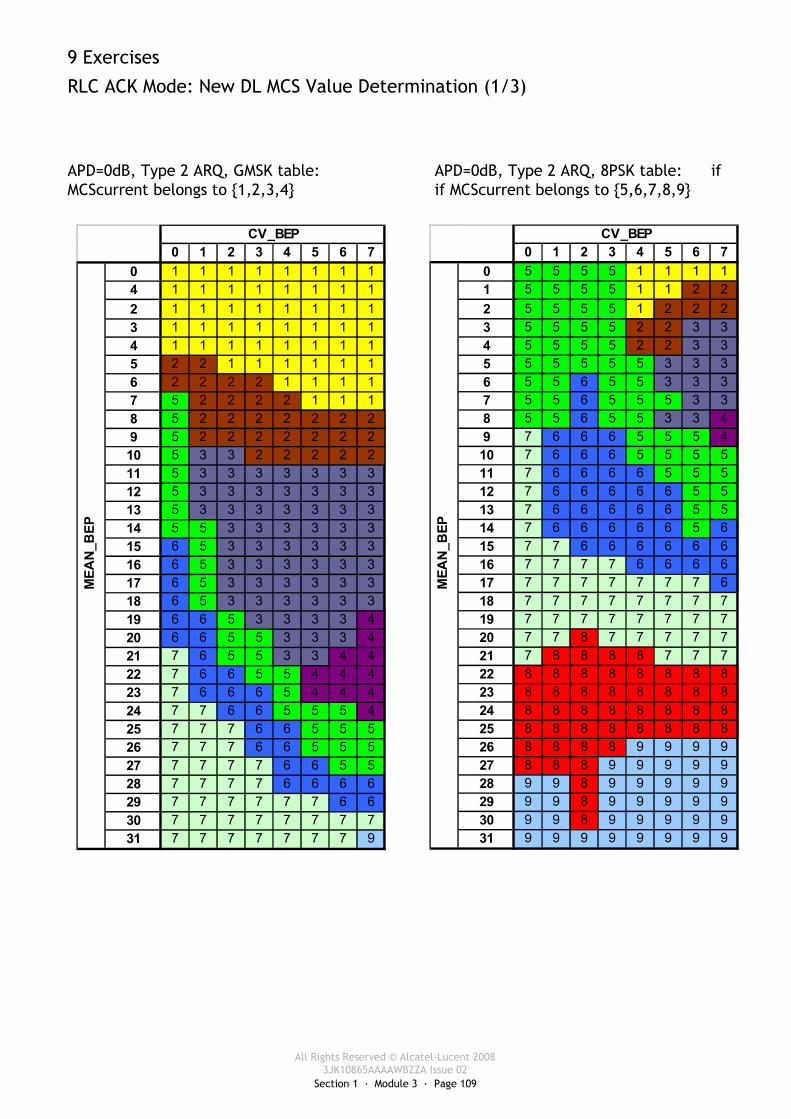
Section 1 · Module 3 · Page 109
All Rights Reserved © Alcatel-Lucent 20083JK10865AAAAWBZZA Issue 02
9 Exercises
RLC ACK Mode: New DL MCS Value Determination (1/3)
APD=0dB, Type 2 ARQ, GMSK table: APD=0dB, Type 2 ARQ, 8PSK table: if MCScurrent belongs to {1,2,3,4} if MCScurrent belongs to {5,6,7,8,9}
0 1 2 3 4 5 6 70 1 1 1 1 1 1 1 14 1 1 1 1 1 1 1 12 1 1 1 1 1 1 1 13 1 1 1 1 1 1 1 14 1 1 1 1 1 1 1 15 2 2 1 1 1 1 1 16 2 2 2 2 1 1 1 17 5 2 2 2 2 1 1 18 5 2 2 2 2 2 2 29 5 2 2 2 2 2 2 210 5 3 3 2 2 2 2 211 5 3 3 3 3 3 3 312 5 3 3 3 3 3 3 313 5 3 3 3 3 3 3 314 5 5 3 3 3 3 3 315 6 5 3 3 3 3 3 316 6 5 3 3 3 3 3 317 6 5 3 3 3 3 3 318 6 5 3 3 3 3 3 319 6 6 5 3 3 3 3 420 6 6 5 5 3 3 3 421 7 6 5 5 3 3 4 422 7 6 6 5 5 4 4 423 7 6 6 6 5 4 4 424 7 7 6 6 5 5 5 425 7 7 7 6 6 5 5 526 7 7 7 6 6 5 5 527 7 7 7 7 6 6 5 528 7 7 7 7 6 6 6 629 7 7 7 7 7 7 6 630 7 7 7 7 7 7 7 731 7 7 7 7 7 7 7 9
CV_BEP
MEA
N_B
EP
0 1 2 3 4 5 6 70 5 5 5 5 1 1 1 11 5 5 5 5 1 1 2 22 5 5 5 5 1 2 2 23 5 5 5 5 2 2 3 34 5 5 5 5 2 2 3 35 5 5 5 5 5 3 3 36 5 5 6 5 5 3 3 37 5 5 6 5 5 5 3 38 5 5 6 5 5 3 3 49 7 6 6 6 5 5 5 410 7 6 6 6 5 5 5 511 7 6 6 6 6 5 5 512 7 6 6 6 6 6 5 513 7 6 6 6 6 6 5 514 7 6 6 6 6 6 5 615 7 7 6 6 6 6 6 616 7 7 7 7 6 6 6 617 7 7 7 7 7 7 7 618 7 7 7 7 7 7 7 719 7 7 7 7 7 7 7 720 7 7 8 7 7 7 7 721 7 8 8 8 8 7 7 722 8 8 8 8 8 8 8 823 8 8 8 8 8 8 8 824 8 8 8 8 8 8 8 825 8 8 8 8 8 8 8 826 8 8 8 8 9 9 9 927 8 8 8 9 9 9 9 928 9 9 8 9 9 9 9 929 9 9 8 9 9 9 9 930 9 9 8 9 9 9 9 931 9 9 9 9 9 9 9 9
CV_BEP
MEA
N_B
EP
Section 1 · Module 3 · Page 110
All Rights Reserved © Alcatel-Lucent 20083JK10865AAAAWBZZA Issue 02
All Rights Reserved © Alcatel-Lucent 2008
EVOLIUM · E-GPRS Radio Algorithms and Parameters Description B10Radio Algorithms · Radio Link Control1 · 3 · 110
9 Exercises
RLC ACK Mode: New DL MCS Value Determination [cont.]
� Using the previous LA tables and the following information, fill in the next table:� APD = 0 dB� DL RLC mode = ACK� MS OUT OF MEMORY = Off
Time allowed:
10 minutes
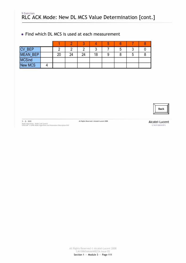
Section 1 · Module 3 · Page 111
All Rights Reserved © Alcatel-Lucent 20083JK10865AAAAWBZZA Issue 02
All Rights Reserved © Alcatel-Lucent 2008
EVOLIUM · E-GPRS Radio Algorithms and Parameters Description B10Radio Algorithms · Radio Link Control1 · 3 · 111
9 Exercises
RLC ACK Mode: New DL MCS Value Determination [cont.]
� Find which DL MCS is used at each measurement
Back
1 2 3 4 5 6 7 8CV_BEP 2 2 2 3 7 5 3 0MEAN_BEP 20 24 24 18 9 8 5 8MCSindNew MCS 4
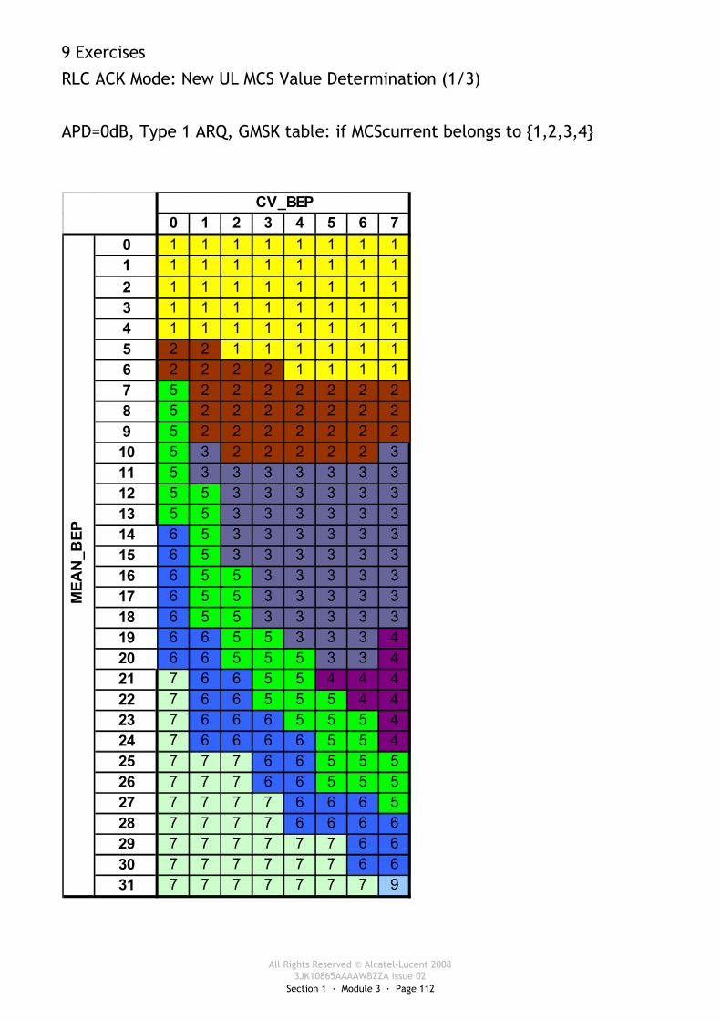
Section 1 · Module 3 · Page 112
All Rights Reserved © Alcatel-Lucent 20083JK10865AAAAWBZZA Issue 02
9 Exercises
RLC ACK Mode: New UL MCS Value Determination (1/3)
APD=0dB, Type 1 ARQ, GMSK table: if MCScurrent belongs to {1,2,3,4}
0 1 2 3 4 5 6 70 1 1 1 1 1 1 1 11 1 1 1 1 1 1 1 12 1 1 1 1 1 1 1 13 1 1 1 1 1 1 1 14 1 1 1 1 1 1 1 15 2 2 1 1 1 1 1 16 2 2 2 2 1 1 1 17 5 2 2 2 2 2 2 28 5 2 2 2 2 2 2 29 5 2 2 2 2 2 2 210 5 3 2 2 2 2 2 311 5 3 3 3 3 3 3 312 5 5 3 3 3 3 3 313 5 5 3 3 3 3 3 314 6 5 3 3 3 3 3 315 6 5 3 3 3 3 3 316 6 5 5 3 3 3 3 317 6 5 5 3 3 3 3 318 6 5 5 3 3 3 3 319 6 6 5 5 3 3 3 420 6 6 5 5 5 3 3 421 7 6 6 5 5 4 4 422 7 6 6 5 5 5 4 423 7 6 6 6 5 5 5 424 7 6 6 6 6 5 5 425 7 7 7 6 6 5 5 526 7 7 7 6 6 5 5 527 7 7 7 7 6 6 6 528 7 7 7 7 6 6 6 629 7 7 7 7 7 7 6 630 7 7 7 7 7 7 6 631 7 7 7 7 7 7 7 9
CV_BEP
MEA
N_B
EP

Section 1 · Module 3 · Page 113
All Rights Reserved © Alcatel-Lucent 20083JK10865AAAAWBZZA Issue 02
All Rights Reserved © Alcatel-Lucent 2008
EVOLIUM · E-GPRS Radio Algorithms and Parameters Description B10Radio Algorithms · Radio Link Control1 · 3 · 113
9 Exercises
RLC ACK Mode: New UL MCS Value Determination [cont.]
� Using the previous LA table and the following information, fill in the next table:� APD = 0 dB� UL RLC mode = ACK� EN_RESEGMENTATION_UL = enabled
Time allowed:
20 minutes
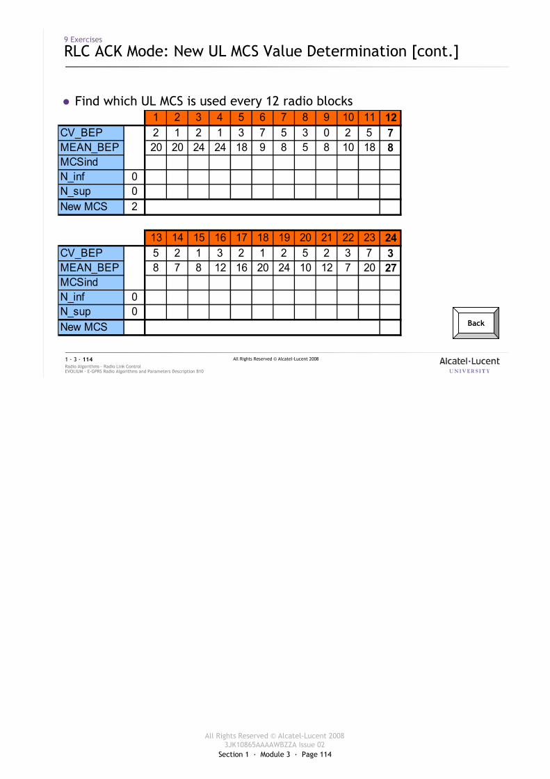
Section 1 · Module 3 · Page 114
All Rights Reserved © Alcatel-Lucent 20083JK10865AAAAWBZZA Issue 02
All Rights Reserved © Alcatel-Lucent 2008
EVOLIUM · E-GPRS Radio Algorithms and Parameters Description B10Radio Algorithms · Radio Link Control1 · 3 · 114
9 Exercises
RLC ACK Mode: New UL MCS Value Determination [cont.]
� Find which UL MCS is used every 12 radio blocks
Back
1 2 3 4 5 6 7 8 9 10 11 12CV_BEP 2 1 2 1 3 7 5 3 0 2 5 7MEAN_BEP 20 20 24 24 18 9 8 5 8 10 18 8MCSindN_inf 0N_sup 0New MCS 2
13 14 15 16 17 18 19 20 21 22 23 24CV_BEP 5 2 1 3 2 1 2 5 2 3 7 3MEAN_BEP 8 7 8 12 16 20 24 10 12 7 20 27MCSindN_inf 0N_sup 0New MCS
Section 1 · Module 3 · Page 115
All Rights Reserved © Alcatel-Lucent 20083JK10865AAAAWBZZA Issue 02
All Rights Reserved © Alcatel-Lucent 2008
EVOLIUM · E-GPRS Radio Algorithms and Parameters Description B10Radio Algorithms · Radio Link Control1 · 3 · 115
9 Exercises
Type II ARQ Mechanism
� Replace the ‘?’ by the right values in the 6 next cases:� Cases 1a, 1b and 1c:� MS OUT OF MEMORY = Off� EN_FULL_IR_DL = disabled
� Case 2:� MS OUT OF MEMORY = Off� EN_FULL_IR_DL = enabled
� Cases 3a and 3b:� MS OUT OF MEMORY = On� EN_FULL_IR_DL = disabled
Time allowed:
20 minutes
Back
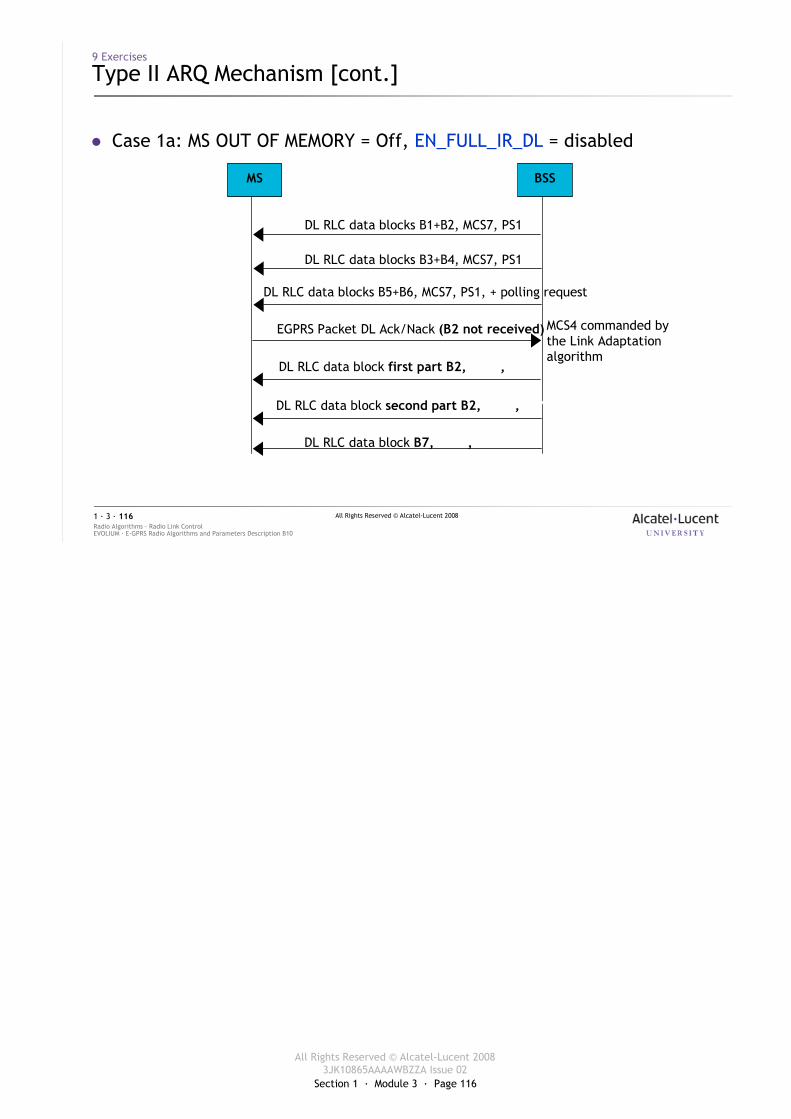
Section 1 · Module 3 · Page 116
All Rights Reserved © Alcatel-Lucent 20083JK10865AAAAWBZZA Issue 02
All Rights Reserved © Alcatel-Lucent 2008
EVOLIUM · E-GPRS Radio Algorithms and Parameters Description B10Radio Algorithms · Radio Link Control1 · 3 · 116
� Case 1a: MS OUT OF MEMORY = Off, EN_FULL_IR_DL = disabled
MS BSS
DL RLC data block first part B2, MCS?, PS?
EGPRS Packet DL Ack/Nack (B2 not received)
DL RLC data block second part B2, MCS?, PS?
DL RLC data blocks B3+B4, MCS7, PS1
DL RLC data blocks B5+B6, MCS7, PS1, + polling request
MCS4 commanded by the Link Adaptation algorithm
DL RLC data blocks B1+B2, MCS7, PS1
DL RLC data block B7, MCS?, PS?
9 Exercises
Type II ARQ Mechanism [cont.]
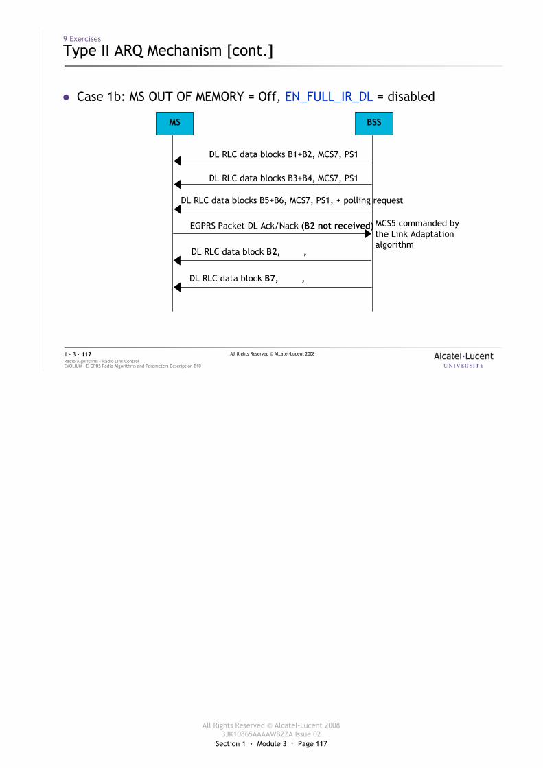
Section 1 · Module 3 · Page 117
All Rights Reserved © Alcatel-Lucent 20083JK10865AAAAWBZZA Issue 02
All Rights Reserved © Alcatel-Lucent 2008
EVOLIUM · E-GPRS Radio Algorithms and Parameters Description B10Radio Algorithms · Radio Link Control1 · 3 · 117
� Case 1b: MS OUT OF MEMORY = Off, EN_FULL_IR_DL = disabled
MS BSS
DL RLC data block B2, MCS?, PS?
EGPRS Packet DL Ack/Nack (B2 not received)
DL RLC data block B7, MCS?, PS?
DL RLC data blocks B3+B4, MCS7, PS1
DL RLC data blocks B5+B6, MCS7, PS1, + polling request
MCS5 commanded by the Link Adaptation algorithm
DL RLC data blocks B1+B2, MCS7, PS1
9 Exercises
Type II ARQ Mechanism [cont.]
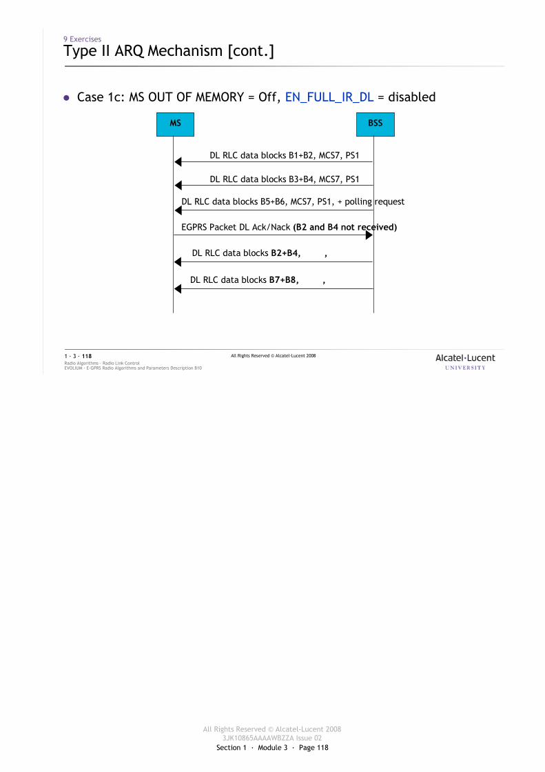
Section 1 · Module 3 · Page 118
All Rights Reserved © Alcatel-Lucent 20083JK10865AAAAWBZZA Issue 02
All Rights Reserved © Alcatel-Lucent 2008
EVOLIUM · E-GPRS Radio Algorithms and Parameters Description B10Radio Algorithms · Radio Link Control1 · 3 · 118
� Case 1c: MS OUT OF MEMORY = Off, EN_FULL_IR_DL = disabled
MS BSS
DL RLC data blocks B2+B4, MCS?, PS?
EGPRS Packet DL Ack/Nack (B2 and B4 not received)
DL RLC data blocks B7+B8, MCS?, PS?
DL RLC data blocks B3+B4, MCS7, PS1
DL RLC data blocks B5+B6, MCS7, PS1, + polling request
DL RLC data blocks B1+B2, MCS7, PS1
9 Exercises
Type II ARQ Mechanism [cont.]
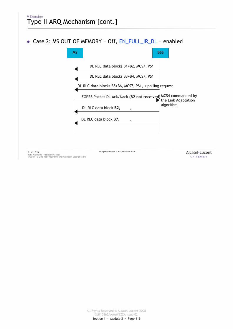
Section 1 · Module 3 · Page 119
All Rights Reserved © Alcatel-Lucent 20083JK10865AAAAWBZZA Issue 02
All Rights Reserved © Alcatel-Lucent 2008
EVOLIUM · E-GPRS Radio Algorithms and Parameters Description B10Radio Algorithms · Radio Link Control1 · 3 · 119
� Case 2: MS OUT OF MEMORY = Off, EN_FULL_IR_DL = enabled
MS BSS
DL RLC data block B2, MCS?, PS?
EGPRS Packet DL Ack/Nack (B2 not received)
DL RLC data block B7, MCS?, PS?
DL RLC data blocks B3+B4, MCS7, PS1
DL RLC data blocks B5+B6, MCS7, PS1, + polling request
MCS4 commanded by the Link Adaptation algorithm
DL RLC data blocks B1+B2, MCS7, PS1
9 Exercises
Type II ARQ Mechanism [cont.]
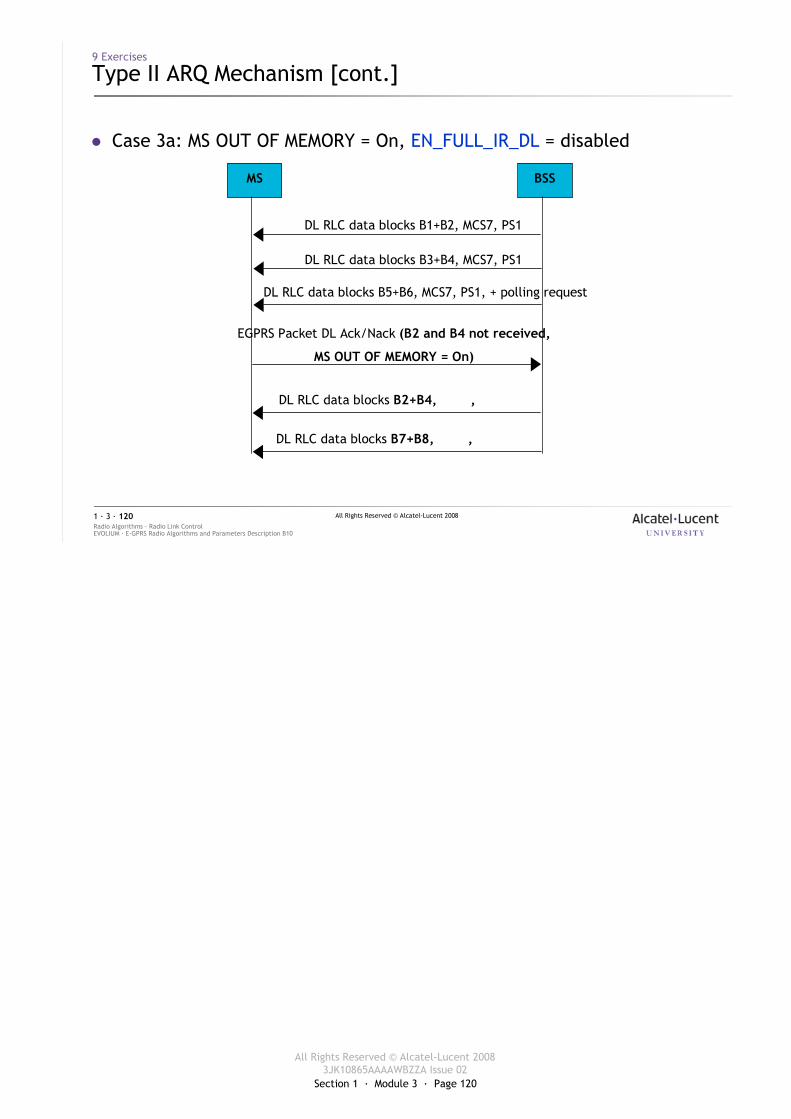
Section 1 · Module 3 · Page 120
All Rights Reserved © Alcatel-Lucent 20083JK10865AAAAWBZZA Issue 02
All Rights Reserved © Alcatel-Lucent 2008
EVOLIUM · E-GPRS Radio Algorithms and Parameters Description B10Radio Algorithms · Radio Link Control1 · 3 · 120
� Case 3a: MS OUT OF MEMORY = On, EN_FULL_IR_DL = disabled
MS BSS
DL RLC data blocks B2+B4, MCS?, PS?
EGPRS Packet DL Ack/Nack (B2 and B4 not received,
MS OUT OF MEMORY = On)
DL RLC data blocks B7+B8, MCS?, PS?
DL RLC data blocks B3+B4, MCS7, PS1
DL RLC data blocks B5+B6, MCS7, PS1, + polling request
DL RLC data blocks B1+B2, MCS7, PS1
9 Exercises
Type II ARQ Mechanism [cont.]
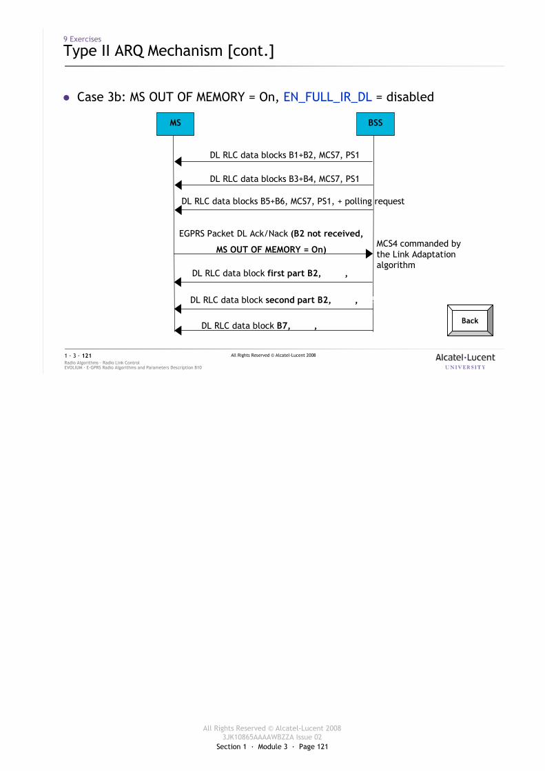
Section 1 · Module 3 · Page 121
All Rights Reserved © Alcatel-Lucent 20083JK10865AAAAWBZZA Issue 02
All Rights Reserved © Alcatel-Lucent 2008
EVOLIUM · E-GPRS Radio Algorithms and Parameters Description B10Radio Algorithms · Radio Link Control1 · 3 · 121
� Case 3b: MS OUT OF MEMORY = On, EN_FULL_IR_DL = disabled
MS BSS
DL RLC data block first part B2, MCS?, PS?
EGPRS Packet DL Ack/Nack (B2 not received,
MS OUT OF MEMORY = On)
DL RLC data block second part B2, MCS?, PS?
DL RLC data blocks B3+B4, MCS7, PS1
DL RLC data blocks B5+B6, MCS7, PS1, + polling request
MCS4 commanded by the Link Adaptation algorithm
DL RLC data blocks B1+B2, MCS7, PS1
DL RLC data block B7, MCS?, PS?
9 Exercises
Type II ARQ Mechanism [cont.]
Back
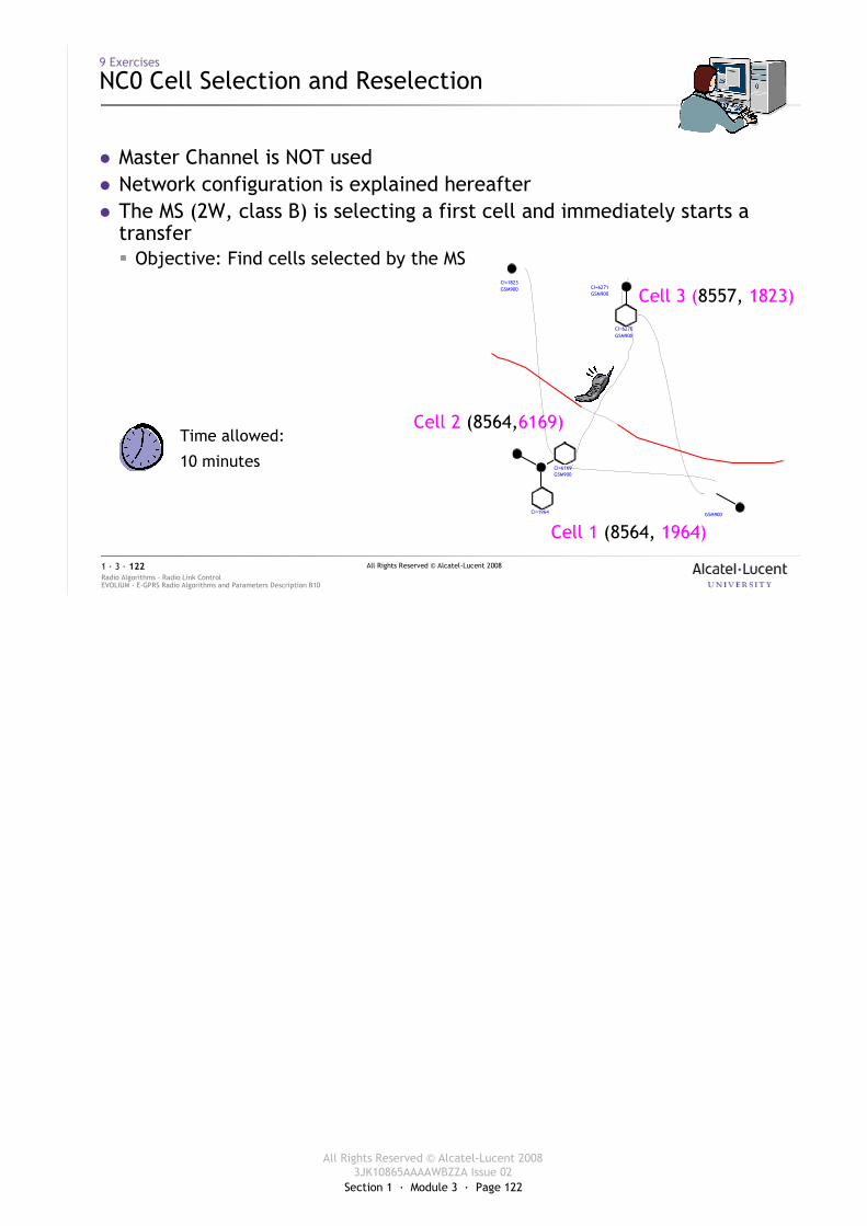
Section 1 · Module 3 · Page 122
All Rights Reserved © Alcatel-Lucent 20083JK10865AAAAWBZZA Issue 02
All Rights Reserved © Alcatel-Lucent 2008
EVOLIUM · E-GPRS Radio Algorithms and Parameters Description B10Radio Algorithms · Radio Link Control1 · 3 · 122
9 Exercises
NC0 Cell Selection and Reselection
� Master Channel is NOT used� Network configuration is explained hereafter� The MS (2W, class B) is selecting a first cell and immediately starts a
transfer� Objective: Find cells selected by the MS
Time allowed:
10 minutes CI=6169GSM900
CI=1823GSM900
CI=1964 GSM900
CI=6270GSM900
CI=6271GSM900 Cell 3 (8557, 1823)
Cell 2 (8564,6169)
Cell 1 (8564, 1964)
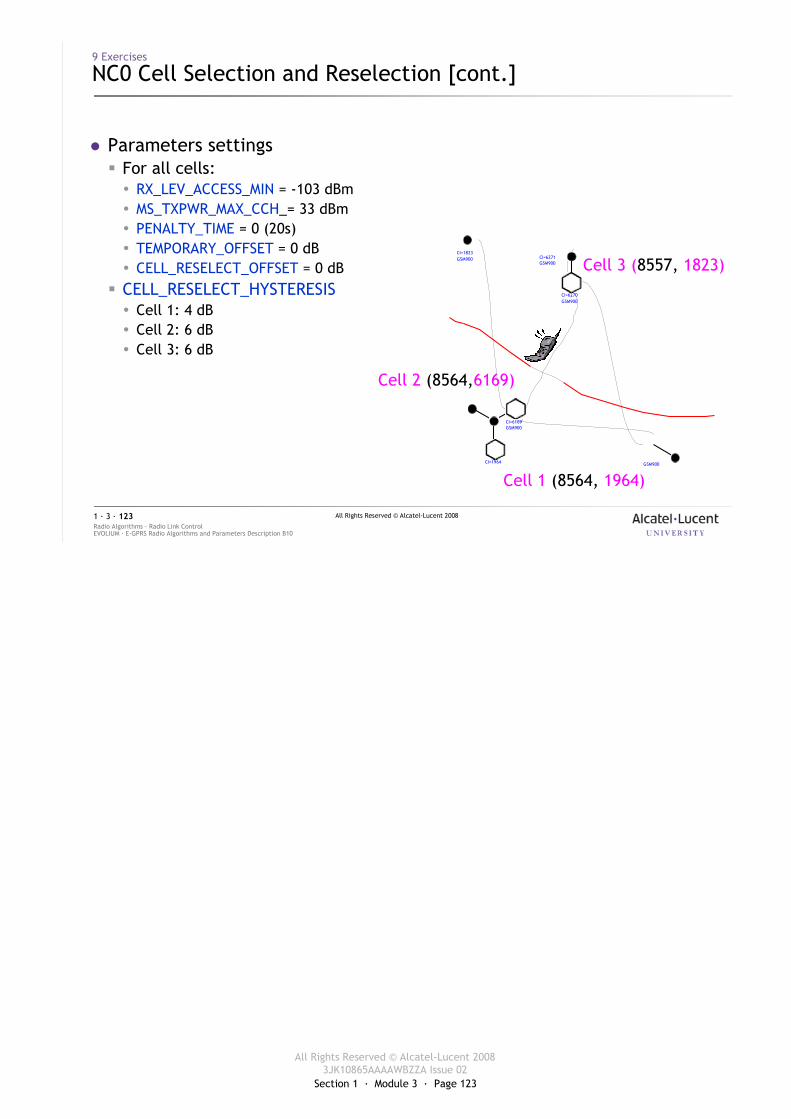
Section 1 · Module 3 · Page 123
All Rights Reserved © Alcatel-Lucent 20083JK10865AAAAWBZZA Issue 02
All Rights Reserved © Alcatel-Lucent 2008
EVOLIUM · E-GPRS Radio Algorithms and Parameters Description B10Radio Algorithms · Radio Link Control1 · 3 · 123
9 Exercises
NC0 Cell Selection and Reselection [cont.]
� Parameters settings� For all cells:� RX_LEV_ACCESS_MIN = -103 dBm� MS_TXPWR_MAX_CCH_= 33 dBm� PENALTY_TIME = 0 (20s)� TEMPORARY_OFFSET = 0 dB� CELL_RESELECT_OFFSET = 0 dB
� CELL_RESELECT_HYSTERESIS� Cell 1: 4 dB� Cell 2: 6 dB� Cell 3: 6 dB
CI=6169GSM900
CI=1823GSM900
CI=1964 GSM900
CI=6270GSM900
CI=6271GSM900 Cell 3 (8557, 1823)
Cell 2 (8564,6169)
Cell 1 (8564, 1964)
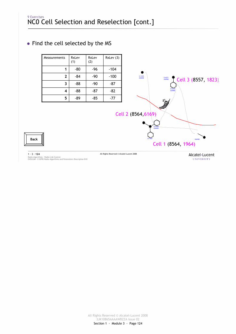
Section 1 · Module 3 · Page 124
All Rights Reserved © Alcatel-Lucent 20083JK10865AAAAWBZZA Issue 02
All Rights Reserved © Alcatel-Lucent 2008
EVOLIUM · E-GPRS Radio Algorithms and Parameters Description B10Radio Algorithms · Radio Link Control1 · 3 · 124
9 Exercises
NC0 Cell Selection and Reselection [cont.]
� Find the cell selected by the MS
CI=6169GSM900
CI=1823GSM900
CI=1964 GSM900
CI=6270GSM900
CI=6271GSM900 Cell 3 (8557, 1823)
Cell 2 (8564,6169)
Cell 1 (8564, 1964)
5
4
3
2
1
Measurements
-77-85-89
-82-87-88
-87-90-88
-100-90-84
-104-96-80
RxLev (3)RxLev(2)
RxLev(1)
Back
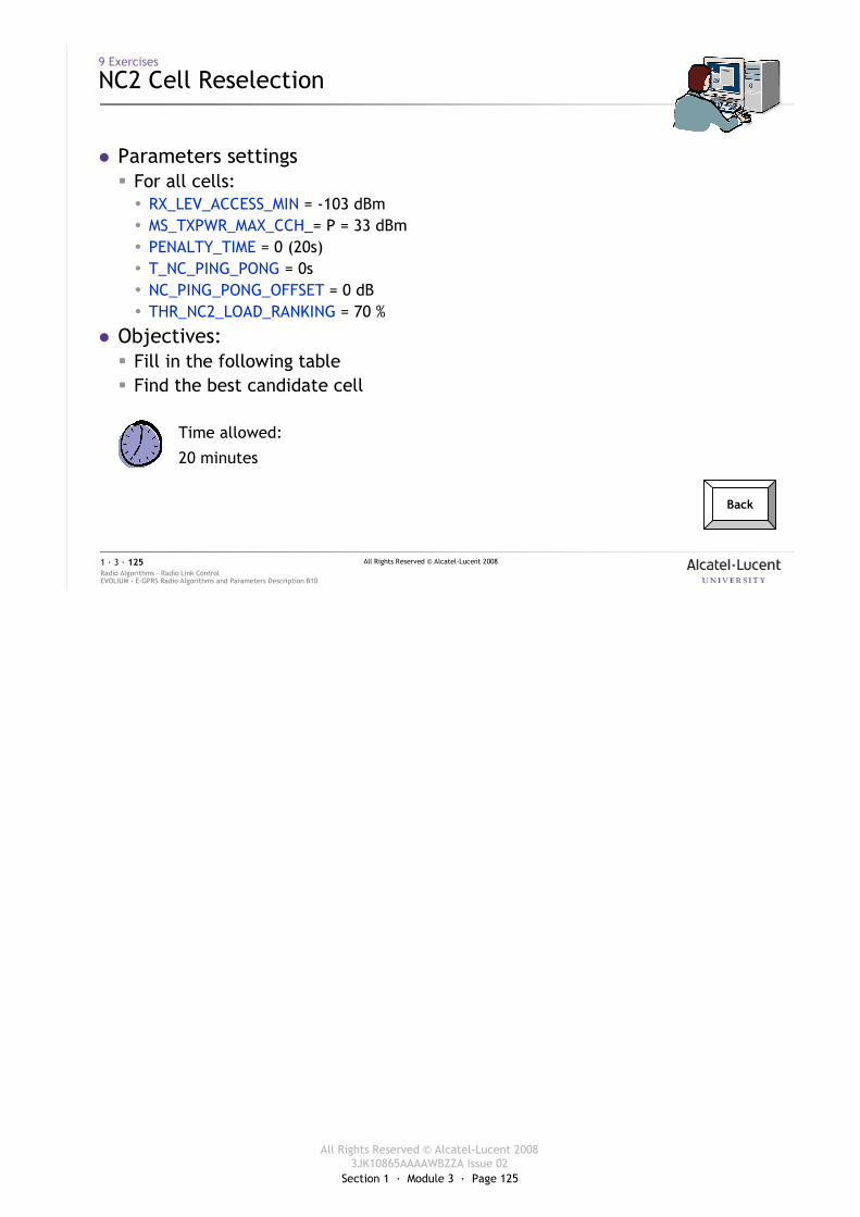
Section 1 · Module 3 · Page 125
All Rights Reserved © Alcatel-Lucent 20083JK10865AAAAWBZZA Issue 02
All Rights Reserved © Alcatel-Lucent 2008
EVOLIUM · E-GPRS Radio Algorithms and Parameters Description B10Radio Algorithms · Radio Link Control1 · 3 · 125
9 Exercises
NC2 Cell Reselection
� Parameters settings� For all cells:� RX_LEV_ACCESS_MIN = -103 dBm� MS_TXPWR_MAX_CCH_= P = 33 dBm� PENALTY_TIME = 0 (20s)� T_NC_PING_PONG = 0s� NC_PING_PONG_OFFSET = 0 dB� THR_NC2_LOAD_RANKING = 70 %
� Objectives:� Fill in the following table� Find the best candidate cell
Time allowed:
20 minutes
Back
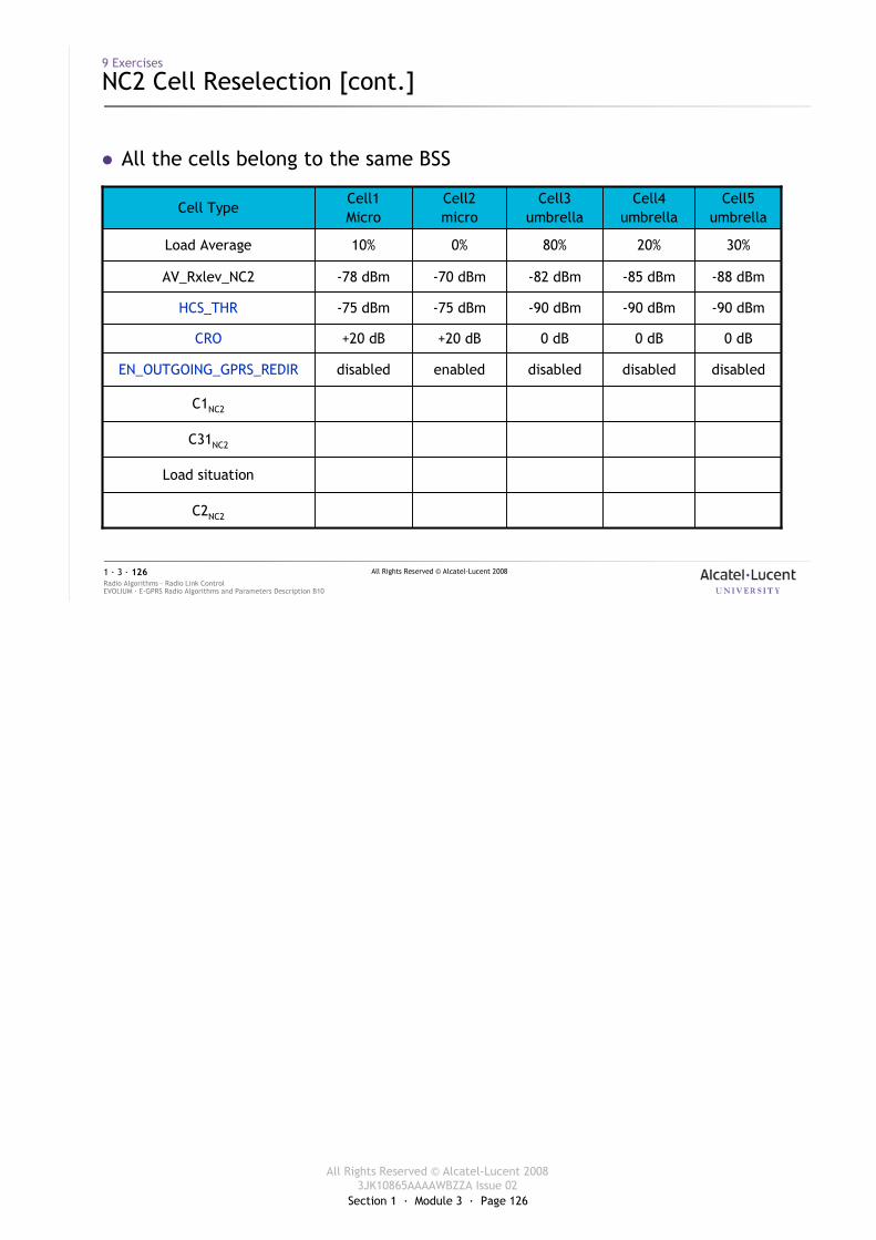
Section 1 · Module 3 · Page 126
All Rights Reserved © Alcatel-Lucent 20083JK10865AAAAWBZZA Issue 02
All Rights Reserved © Alcatel-Lucent 2008
EVOLIUM · E-GPRS Radio Algorithms and Parameters Description B10Radio Algorithms · Radio Link Control1 · 3 · 126
9 Exercises
NC2 Cell Reselection [cont.]
� All the cells belong to the same BSS
C2NC2
Load situation
C31NC2
C1NC2
disableddisableddisabledenableddisabledEN_OUTGOING_GPRS_REDIR
0 dB0 dB0 dB+20 dB+20 dBCRO
-90 dBm-90 dBm-90 dBm-75 dBm-75 dBmHCS_THR
-88 dBm-85 dBm-82 dBm-70 dBm-78 dBmAV_Rxlev_NC2
30%20%80%0%10%Load Average
Cell5umbrella
Cell4umbrella
Cell3umbrella
Cell2micro
Cell1Micro
Cell Type
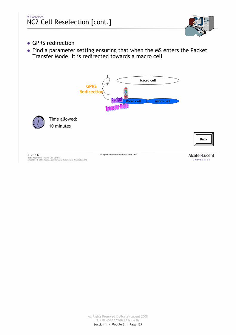
Section 1 · Module 3 · Page 127
All Rights Reserved © Alcatel-Lucent 20083JK10865AAAAWBZZA Issue 02
All Rights Reserved © Alcatel-Lucent 2008
EVOLIUM · E-GPRS Radio Algorithms and Parameters Description B10Radio Algorithms · Radio Link Control1 · 3 · 127
9 Exercises
NC2 Cell Reselection [cont.]
� GPRS redirection� Find a parameter setting ensuring that when the MS enters the Packet
Transfer Mode, it is redirected towards a macro cell
Time allowed:
10 minutes
Back
Macro cell
Micro cell Micro cell
GPRSRedirection
Section 1 · Module 3 · Page 128
All Rights Reserved © Alcatel-Lucent 20083JK10865AAAAWBZZA Issue 02
All Rights Reserved © Alcatel-Lucent 2008
EVOLIUM · E-GPRS Radio Algorithms and Parameters Description B10Radio Algorithms · Radio Link Control1 · 3 · 128
9 Exercises
Radio Link Supervision
� List in the DL and UL the different cases of abnormal release.
Time allowed:
10 minutes
Section 1 · Module 3 · Page 129
All Rights Reserved © Alcatel-Lucent 20083JK10865AAAAWBZZA Issue 02
All Rights Reserved © Alcatel-Lucent 2008
EVOLIUM · E-GPRS Radio Algorithms and Parameters Description B10Radio Algorithms · Radio Link Control1 · 3 · 129
Self-assessment on the Objectives
� Please be reminded to fill in the formSelf-Assessment on the Objectivesfor this module
� The form can be found in the first partof this course documentation
Section 1 · Module 3 · Page 130
All Rights Reserved © Alcatel-Lucent 20083JK10865AAAAWBZZA Issue 02
All Rights Reserved © Alcatel-Lucent 2008
EVOLIUM · E-GPRS Radio Algorithms and Parameters Description B10Radio Algorithms · Radio Link Control1 · 3 · 130
End of ModuleRadio Link Control