Embed Size (px)
Citation preview
John W. Wilson Old Dominion University, Norfolk, Virginia
Tony C. Slaba Langley Research Center, Hampton, Virginia
Francis F. Badavi Old Dominion University, Norfolk, Virginia
Brandon D. Reddell and Amir A. Bahadori Johnson Space Center, Houston, Texas
https://ntrs.nasa.gov/search.jsp?R=20150002822 2018-06-16T23:33:54+00:00Z

NASA STI Program . . . in Profile
•
•
•
•
•
•
•
•
•
•

John W. Wilson Old Dominion University, Norfolk, Virginia
Tony C. Slaba Langley Research Center, Hampton, Virginia
Francis F. Badavi Old Dominion University, Norfolk, Virginia
Brandon D. Reddell and Amir A. Bahadori Johnson Space Center, Houston, Texas


Contents
Abstract........................................................................................................................................................... 1
Introduction .................................................................................................................................................... 1
Deterministic Code Development ................................................................................................................... 2
3D Marching Procedures ................................................................................................................................ 4
Simple Homogenous Geometry ...................................................................................................................... 7
Simple Inhomogeneous Geometry ............................................................................................................... 13
Conclusions .................................................................................................................................................. 16
Acknowledgements ...................................................................................................................................... 17
References .................................................................................................................................................... 17
iii

Figures
1. Geometric relations of quantities useful in solving equation (1). The symbol represents a unit normal vector. .......................................................................................................................................... 3
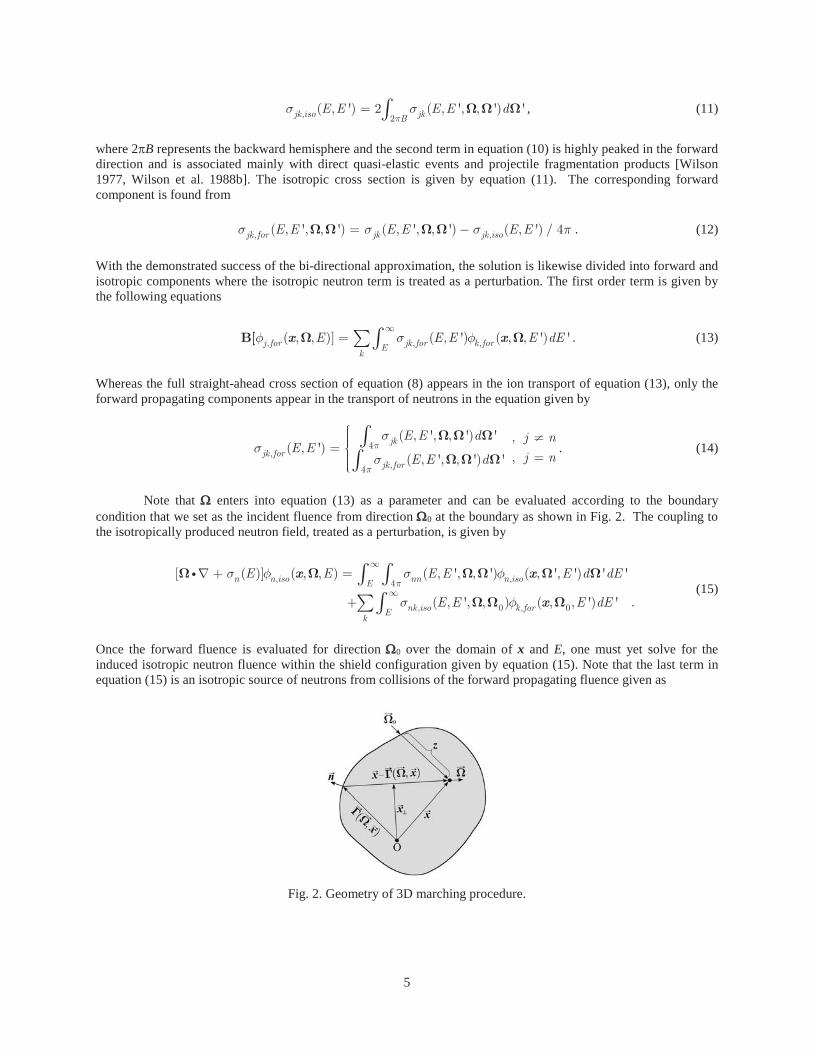
2. Geometry of 3D marching procedure. ..................................................................................................... 5 3. Aluminum slab geometry (top) and associated cube geometry (bottom). The slab is 40 g/cm2 thick with
infinite lateral dimensions. The cube is 40 g/cm2 on all sides. The red circles indicate detector locations at which quantities are evaluated. The green arrows indicate general directions of leakage. .................. 7
4. Convergence test for solution in slab geometry at depths of 35 and 40 g/cm2. ....................................... 8 5. Fluence induced by the Webber SPE event in a 40 g/cm2 cube of aluminum at two depths. .................. 8 6. Comparison of MC evaluated leakage from a cube at 35 and 40 g/cm2 depths. ...................................... 9 7. Aluminum slab geometry (top) and associated sphere geometry (bottom). The slab is 40 g/cm2 thick
with infinite lateral dimensions. The sphere diameter is 40 g/cm2. The red circles indicate detector locations at which quantities are evaluated. The green arrows indicate general directions of leakage. .. 9
8. Isotropic neutron source (E > 1 MeV) distribution in units of neutrons/(g-event) induced by the Webber SPE spectrum in cube and spherical geometry. ....................................................................... 10
9. Particle spectra at detector locations 35 g/cm2 (left pane) and 40 g/cm2 from top of aluminum sphere (diameter 40 g/cm2) exposed to Webber SPE spectrum. ....................................................................... 10
10. Comparison of MC evaluated leakage from a sphere at 35 and 40 g/cm2 depths. ................................. 11 11. Leakage factors for cube and sphere at 35 g/cm2 and 40 g/cm2 evaluated by the 3DHZETRN (N = 22)
code. ...................................................................................................................................................... 11 12. Leakage factors for cube and sphere at 35 g/cm2 and 40 g/cm2 evaluated by the Geant4 MC code. .... 12 13. Leakage factors for cube and sphere at 35 g/cm2 and 40 g/cm2 evaluated by the PHITS MC code. ..... 12 14. Leakage factors for cube and sphere at 35 g/cm2 and 40 g/cm2 evaluated by the FLUKA MC code. ... 13 15. Slab geometry (top) and associated cube geometry (bottom). The slab is 30 g/cm2 (30 cm) of ICRU
tissue with 20 g/cm2 (7.41 cm) of aluminum above and below and infinite lateral dimensions. The cube has the same thickness of ICRU tissue and aluminum and has lateral dimensions of 44.82 cm. The red circles indicate detector locations at which quantities are evaluated. The green arrows indicate general directions of leakage. ............................................................................................................................. 13
16. Convergence test in an inhomogeneous slab composed of a 30 cm ICRU tissue slab shielded above and below by 7.41 cm of aluminum exposed to the Webber SPE spectrum. Results shown at 0 cm (left pane) and 30 cm (right pane), corresponding to the top and bottom detector locations, as shown in Fig. 15, respectively. ..................................................................................................................................... 14
17. Isotropic neutron source (E > 1 MeV) distribution in units of neutrons/(g-event) induced by the Webber SPE in the rectangular box and shielded sphere. The intensity (color) scale has been adjusted to more clearly show the shadow cast by the tissue sphere. .................................................................. 14
18. Particle spectra at detector locations 0 cm (left pane) and 30 cm (right pane) from top of the tissue box (thickness 30 cm) shielded by aluminum above and below (thickness 7.41 cm) exposed to the Webber SPE spectrum. ....................................................................................................................................... 15
19. Leakage from an inhomogeneous cube of aluminum/tissue/aluminum as seen at the center of the top interface (x = 0) and the lower interface (x = 30). ................................................................................. 15
20. Slab geometry (top) and associated sphere geometry (bottom). The slab is 30 g/cm2 (30 cm) of ICRU tissue with 20 g/cm2 (7.41 cm) of aluminum above and below and infinite lateral dimensions. The sphere is an ICRU tissue sphere with diameter 30 g/cm2 (30 cm) surrounded by 20 g/cm2 (7.41 cm) aluminum. The red circles indicate detector locations at which quantities are evaluated. The green arrows indicate general directions of leakage. ....................................................................................... 16
21. Particle spectra at detector locations 0 cm (left pane) and 30 cm (right pane) from top of tissue sphere (radius 15 cm) surrounded by an aluminum shell (thickness 7.41 cm) exposed from above by the Webber SPE spectrum. .......................................................................................................................... 16
22. Leakage from an inhomogeneous sphere of aluminum/tissue at the top interface (left pane) and lower interface (right pane). ............................................................................................................................ 17
iv

Abstract A computationally efficient 3DHZETRN code capable of simulating High charge (Z) and Energy (HZE) and light ions (including neutrons) under space-like boundary conditions with enhanced neutron and light ion propagation was recently developed for simple shielded objects. Monte Carlo (MC) benchmarks were used to verify the 3DHZETRN methodology in slab and spherical geometry, and it was shown that 3DHZETRN agrees with MC codes to the degree that various MC codes agree among themselves. One limitation in the verification process is that all of the codes (3DHZETRN and three MC codes) utilize different nuclear models/databases. In the present report, the new algorithm, with well-defined convergence criteria, is used to quantify the neutron leakage from simple geometries to provide means of verifying 3D effects and to provide guidance for further code development.
Introduction
Early nucleon transport code development relied on Monte Carlo (MC) methods using the straight-ahead
approximation [Wright et al 1969]. Further development of a full 3D MC code with the Bertini intranuclear cascade model was used to test the straight-ahead approximation for which resulting dose and dose equivalent were within the statistical uncertainty of the full 3D MC code [Alsmiller et al. 1965]. Such 3D MC codes on computers of that time required vast resources even for small sample sizes [Wright 1966, Alsmiller 1967] and encouraged the development of more efficient means of radiation exposure evaluation. A 3D MC code that sampled a Bertini model derived database giving it much greater computer efficiency was extended to high energies at the NASA Langley Research Center (LaRC) [Lambiotte et al. 1971] for atmospheric and space radiation studies but still required extensive computer resources for realistic calculations [Foelshe et al. 1974]. As a result, NASA LaRC began a search for methods of direct solution of the Boltzmann equation. It was found that proton transport based on direct solution of the straight-ahead Boltzmann equation resulted in an efficient code able to reproduce the straight-ahead MC using the same database [Wilson and Lamkin 1974, 1975; Lamkin 1974; Wright et al. 1969]. As a result, NASA LaRC began a long-term investigation of direct solution of the Boltzmann equation as an alternative to MC methods [Wilson and Lamkin 1974, 1975]. The 3D MC codes would play an indispensable role in these developments as a test for this alternate evaluation scheme.
A major element in developing Boltzmann solution methods is the examination of adequate computer methods, as was first taken up in the straight-ahead approximation following the MC studies of Wright et al. [1969] and Alsmiller et al. [1965]. Both numerical convergence studies [Lamkin 1974] and formal convergence studies following Wilson and Lamkin [1974, 1975] were commissioned. The next formal convergence study examined the straight-ahead approximation itself as a first order asymptotic expansion in terms of angular factors for which it was shown that errors were on the order of the square of the ratio of the beam divergence (few cm) to the radius of curvature of the object (few meters in human rated space systems) [Wilson and Khandelwal 1974]. Additional analysis using the Fredholm version of the Boltzmann equation, along with asymptotic expansion in angular width, demonstrated that the straight-ahead approximation is more accurate than assuming that the High charge (Z) and Energy (HZE) fragments proceed with the same velocity as the projectile ion [Wilson 1977]. Neglect of these higher order terms resulted in reduction of the Fredholm version to a Volterra equation that could be solved using marching procedures [Wilson and Badavi 1986].
Solving the Volterra equation as a perturbation series (Neumann series) allowed direct comparison to 20Ne attenuation experimental data obtained at the Lawrence Berkeley Laboratory's Bevatron [Wilson et al. 1984] revealing the need for an improved nuclear fragmentation model. The initiation of the NUCFRG model allowed improved comparison with atmospheric air shower data [Wilson et al. 1987a,b] and with the 20Ne Bevatron data [Shavers et al. 1990, 1993]. With this success in transporting HZE ions, only the treatment of light ions and neutrons required advancement as a formalism compatible with the HZE marching procedures.
Unlike the HZE fragments that are produced at velocities nearly equal to the projectile ion, neutron and light ion induced reactions produce a broad spectrum of secondary particles and cannot be adequately simplified. This complication was addressed by Wilson et al. [1988a,b] using perturbative methods wherein a closed form solution is first obtained over a small spatial step h and repeated to a depth x = Nh. The approach provided a computationally efficient solution over the whole spatial and energy domain. Such marching procedures are fully compatible with the HZE code and the integration of the baryon transport code (BRYNTRN) into the HZE code provided the initial HZETRN version [Wilson et al. 1991]. Cucinotta [1993] added the remaining light ions
1

(deuteron, triton, helion, and alpha) to BRYNTRN and integrated the revised code into HZETRN. Code verification with analytic solution methods were accomplished by Wilson et al. [1987b], Ganapol et al. [1991], Lamkin [1994], and Shinn et al. [1998]. Code validation was summarized by Shinn et al. [1998]. Later work completed by Slaba et al. [2010a] greatly improved overall code efficiency and reduced numerical discretization error associated with the marching algorithms. Blattnig et al. [2004] and Norman et al. [2012, 2013] also integrated a coupled model for pion and muon transport and the associated electromagnetic cascade. These efforts largely completed the development of HZETRN in the straight-ahead approximation. Further evaluation of the accuracy of the straight-ahead formalism requires formal improvements with added detail to the description that can be taken in two directions: corrections to the straight-ahead approximation or addition to the physical process descriptions within the HZETRN formalism.
An obvious first correction relates to the assumption that even particles produced in the backward hemisphere travel forward in the straight-ahead approximation. Hence as a correction, the backward hemispheric produced neutrons were assumed to travel straight backward as the next level of development (bi-directional approximation). Note, this changes the character of the solution as forward and backward propagation is coupled in the nature of the Fredholm equation. Clowdsley et al. [2000, 2001] solved the forward/backward neutron equations in the multigroup approximation and using collocation methods. Heinbockel et al. [2003] compared additional solution methods among themselves. Slaba et al. [2010b] fully coupled the forward and backward neutron transport equations and improved numerical efficiency by casting the system in a linear algebraic equation format (as a discrete version of the Fredholm equation). Extensive comparisons have been made with available MC codes [Heinbockel et al. 2011a,b; Slaba et al. 2011, 2013] and found to agree with the various MC codes as well as the MC codes agree among themselves.
The next logical step allowing an objective evaluation of the bi-directional approximation error is to allow fuller angular dependence within the Fredholm formalism. A first step was implemented in a perturbative approach in finite objects and compared to MC results [Wilson et al. 2014a,b,c, 2015]. This evaluation of 3D effects by comparing with MC evaluations met with some of the limitations of the various MC codes which use differing nuclear models and databases resulting in large disparity [Heinbockel et al. 2011a,b] so that 3D effects are somewhat obscured [Wilson et al. 2014a,b]. The nuclear cross sections enter in two ways; first, they differ in the overall production of neutrons/light ions among the transport models, and second, they differ in attenuation and scattering cross sections as particles move through materials. Herein, means of reducing the effects of the differing neutron production terms among various transport models will be used to more unambiguously evaluate 3D effects in neutron transport. Deterministic Code Development
The following two sections summarize deterministic code formalism and developments resulting in the HZETRN and 3DHZETRN codes. Much of the information has been documented elsewhere (see in particular Wilson et al. [2014a,b,c, 2015] and references contained therein) but is being included here for completeness.
The relevant transport equations are the linear Boltzmann equations derived on the basis of conservation principles [Wilson et al. 1991, 2005] for the flux (or fluence) density ( , , )j Ex of a j type particle in the continuous slowing down approximation (CSDA) in which atomic processes are described by the stopping power Sj(E) for each ion type j (vanishes for neutrons j = n) as
4
( , , )] ( , ', , ') ( , ', ') ' 'j jk kEk
E E E E d dEx x , (1)
where the differential operator on the left hand side is defined as
1( , , )] ( , , ) ( ) ( , , ) ( ) ( , , )j j j j j j
j
E E S E E E EA E
x x x x . (2)
Equation (1) is solved subject to a boundary condition over the enclosure of the solution domain as shown in Fig. 1. The terms ( )j E and ( , ', , ')jk E E are the media macroscopic cross sections and include nuclear elastic and reaction contributions and have been discussed in more detail elsewhere [Wilson et al. 1991, 2005].
2
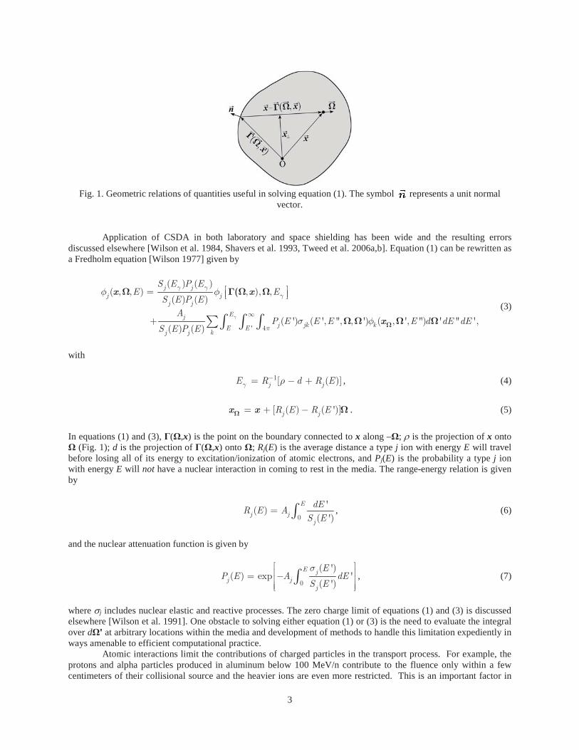
Fig. 1. Geometric relations of quantities useful in solving equation (1). The symbol represents a unit normal
vector.
Application of CSDA in both laboratory and space shielding has been wide and the resulting errors discussed elsewhere [Wilson et al. 1984, Shavers et al. 1993, Tweed et al. 2006a,b]. Equation (1) can be rewritten as a Fredholm equation [Wilson 1977] given by
' 4
( ) ( )( , , ) , ), ,
( ) ( )
( ') ( ', '', , ') ( , ', '') ' '' ' ,( ) ( )
j jj j
j j
Ejj jk kE E
kj j
S E P EE E
S E P EA
P E E E E d dE dES E P E
x x
x
(3)
with 1[ ( )]j jE R d R E , (4) [ ( ) ( ')]j jR E R Ex x . (5) In equations (1) and (3), ( ,x) is the point on the boundary connected to x along – ; is the projection of x onto
(Fig. 1); d is the projection of ( ,x) onto ; Rj(E) is the average distance a type j ion with energy E will travel before losing all of its energy to excitation/ionization of atomic electrons, and Pj(E) is the probability a type j ion with energy E will not have a nuclear interaction in coming to rest in the media. The range-energy relation is given by
0
'( )
( ')
E
j jj
dER E A
S E, (6)
and the nuclear attenuation function is given by
0
( ')( ) exp '
( ')
E jj j
j
EP E A dE
S E, (7)
where j includes nuclear elastic and reactive processes. The zero charge limit of equations (1) and (3) is discussed elsewhere [Wilson et al. 1991]. One obstacle to solving either equation (1) or (3) is the need to evaluate the integral over d at arbitrary locations within the media and development of methods to handle this limitation expediently in ways amenable to efficient computational practice.
Atomic interactions limit the contributions of charged particles in the transport process. For example, the protons and alpha particles produced in aluminum below 100 MeV/n contribute to the fluence only within a few centimeters of their collisional source and the heavier ions are even more restricted. This is an important factor in
3

that the transported secondary charged particle flux tends to be small at low energies and the role of additional nuclear reactions by these low energy ions are likewise limited, an important fact to be implemented later in the current development.
As noted above, a prime limitation in the evaluation of equation (1) or (3) is evaluation of the integral over d at any arbitrary location within the media. The approach to a practical solution of equation (1) or (3) is to develop a progression of solutions from the simple to increasingly complex allowing early implementation of high-performance computational procedures and establishing a converging sequence of approximations with established accuracy criteria and means of verification and validation. The first step leading to the lowest order solution reduces the evaluation by introducing the straight-ahead approximation as guided by the nucleon transport studies of Alsmiller et al. [1965] using Monte Carlo methods in which the differential cross sections were approximated as ( , ', , ') ( , ') ( ')jk jkE E E E , (8) resulting in dose and dose equivalent per unit fluence to be within the statistical uncertainty of the Monte Carlo result obtained using the fully angle dependent cross sections in slab geometry [Wilson et al. 1991].
In the early Boltzmann transport studies of Wilson and Lamkin [1974, 1975] and Lamkin [1974], it was demonstrated that after neutrons are produced by a proton beam, the recoupling of neutrons back to the proton field is limited, but the neutron fields tend to build-up with increasing penetration depth. This mainly occurs since many protons produced by neutron-induced reactions are of lower energy and are quickly removed by atomic interactions (especially the isotropically produced protons). The probability of even a 100 MeV proton to undergo a nuclear reaction is only several percent. The low energy neutrons on the other hand have no effective atomic interactions and propagate until a nuclear interaction occurs or they escape from the media. Yet, the low energy protons and other light ions produced in tissue through neutron collisions contribute significantly to biological injury and must be represented [Foelsche et al. 1974]. This was the basis of the studies of Heinbockel and co-workers [2003] starting with Clowdsley et al. [2000, 2001] using the NUCFRG2 nuclear database [Wilson et al. 1987a, 1995, 1998].
Development of an algorithm for solving equation (1) or (3) is expedited by approximating the double differential cross sections as
, ,( , ', , ') ( , ') ( ') ( , ') ( ')nn nn f nn bE E E E E E . (9) Unlike the straight-ahead approximation that reduces equation (3) to a Volterra equation, this bi-directional equation (9) results in a new approximate Fredholm equation that can be solved by a perturbative expansion or other means as examined by Heinbockel and coworkers. Whereas the straight-ahead solution accounts for leakage only at the distal surface, this bi-directional solution provides estimates of the albedo neutron leakage. Although improvements in quality of solution can be judged by direct comparison of the differences in the bi-directional solution and the straight-ahead values, the overall quality as judged by other codes are limited by the use of differing nuclear databases. Still, among the MC codes available, it has been shown that the bi-directional code agrees with MC codes to the extent that MC codes agree among themselves in slab geometry [Heinbockel et al. 2011a,b, Slaba et al. 2011, 2013]. Considered in the subsequent section is the transport in finite objects in which lateral leakage can play an important role. 3D Marching Procedures
A sequence of approximations that spans the formalism from the simple straight-ahead approximation to
more complex propagation algorithms is now developed [Wilson et al. 2014a,b,c, 2015]. The governing equation in the CSDA ignoring Coulomb scattering is given by equations (1) and (3). The double differential cross sections are found to be closely approximated by a forward component and an isotropic component given by
, ,( , ', , ') ( , ') / 4 ( , ', , ')jk jk iso jk forE E E E E E , (10) where the first term is isotropic and associated with lower-energy particles produced including target fragments defined by
4
, 2( , ') 2 ( , ', , ') 'jk iso jkBE E E E d , (11)
where 2 B represents the backward hemisphere and the second term in equation (10) is highly peaked in the forward direction and is associated mainly with direct quasi-elastic events and projectile fragmentation products [Wilson 1977, Wilson et al. 1988b]. The isotropic cross section is given by equation (11). The corresponding forward component is found from , ,( , ', , ') ( , ', , ') ( , ') / 4jk for jk jk isoE E E E E E . (12) With the demonstrated success of the bi-directional approximation, the solution is likewise divided into forward and isotropic components where the isotropic neutron term is treated as a perturbation. The first order term is given by the following equations
, , ,( , , )] ( , ') ( , , ') 'j for jk for k forEk
E E E E dEx x . (13)
Whereas the full straight-ahead cross section of equation (8) appears in the ion transport of equation (13), only the forward propagating components appear in the transport of neutrons in the equation given by
4,
,4
( , ', , ') ' ,( , ')
,( , ', , ') '
jkjk for
jk for
E E d j nE E
j nE E d. (14)
Note that enters into equation (13) as a parameter and can be evaluated according to the boundary
condition that we set as the incident fluence from direction 0 at the boundary as shown in Fig. 2. The coupling to the isotropically produced neutron field, treated as a perturbation, is given by
, ,4
, 0 , 0
[ ( )] ( , , ) ( , ', , ') ( , ', ') ' '
( , ', , ) ( , , ') ' .
n n iso nn n isoE
nk iso k forEk
E E E E E d dE
E E E dE
x x
x (15)
Once the forward fluence is evaluated for direction 0 over the domain of x and E, one must yet solve for the induced isotropic neutron fluence within the shield configuration given by equation (15). Note that the last term in equation (15) is an isotropic source of neutrons from collisions of the forward propagating fluence given as
Fig. 2. Geometry of 3D marching procedure.
5

, 0 , 0 , 0( , , ) ( , ', , ) ( , , ') 'n iso nk iso k forEk
E E E E dEx x , (16)
for which the forward fluence , 0( , , ')k for Ex is a function of the penetration depth z (Fig. 2) along the direction
0. This is denoted by introducing , 0 , 0[ ( ), , ] ( , , )n iso n isoz E Ex x where z(x) is the penetration depth
along 0 to the point x. Equation (15) is rewritten as
, ,4
, 0
[ ( )] ( , , ) ( , ', , ') ( , ', ') ' '
[ ( ), , ] .n n iso nn n isoE
n iso
E E E E E d dE
z E
x x
x (17)
Note that equation (17) also provides a basis for introducing anisotropic source terms as well. Whereas the forward propagating solution has its source fixed by the boundary condition, the isotropic solution (having no inbound fluence) is driven by internal sources generated by the collisions of the inbound fluence as modified by the forward propagator in penetrating to x along direction 0. In evaluating the penetration depth, one must account for differences in the material composition that determines the attenuation in reaching x from the boundary in addition to the strength of the neutron source term at location x. It is clear that enters equation (17) as a parameter and can be solved along an arbitrary number of rays used to construct a numerical representation of , ( , , )n iso Ex whose dependence comes from the distance to the
boundary t( ) and the penetration depth z along 0. The isotropic neutron source of equation (17) effectively decouples the incident direction 0 from the neutron direction of propagation . To solve equation (17), the neutron fluence, , ( , , )n iso Ex , must be known at every x from all directions ' approaching x from adjacent locations.
Although the use of approximation (9), based on the assumption that losses along the ray are compensated by diffusion from adjacent rays, is a demonstrated useful assumption in a semi-infinite slab [Wilson et al. 2014a,b], it is an approximate overestimate in any finite object. Still, using equation (9) in evaluation of equation (17) seems a reasonable approximation in most human rated vehicles leading to an extension of transport along an arbitrary ray
as a solution to the bi-directional equations
, , ,
, ,
, 0
( )] ( , , ) ( , ') ( , , ') '
( , ') ( , , ') '
[ ( ), , , ] ,
n n iso nn f n isoE
nn b n isoE
n iso
E E E E E dE
E E E dE
z E
x x
x
x
(18)
where the backward moving field satisfies a similar equation obtained by replacing by - in equation (18) as
, , ,
, ,
, 0
( )] ( , , ) ( , ') ( , , ') '
( , ') ( , , ') '
[ ( ), , , ] .
n n iso nn f n isoE
nn b n isoE
n iso
E E E E E dE
E E E dE
z E
x x
x
x
(19)
These isotropically produced neutrons produce isotropic light ions in collisions with the media resulting in a light ion fluence given approximately by
, ,1
( , , ) ( ) ( , , ) ( , ') ( , , ') 'j j j iso jn n isoEj
E S E E E E E dEA E
x x x , (20)
6

where , ( , , )n iso Ex is the isotropically produced neutron fluence. Equations (18) and (19) are solved
simultaneously for no additional external fluence incident on the media directed along (see Fig. 2). Note that the implicit assumption of equations (18) and (19) is that lateral diffusion from the ray is fully compensated by diffusion from adjacent rays. This has been demonstrated as a reasonable assumption for slab geometry [Heinbockel et al. 2011a,b; Slaba et al. 2011, 2013; Wilson et al. 2014a,b,c, 2015]. The lateral leakage along 0 in this case is found to a first order approximation by solving equations (18) and (19) along each i between the ray limits {-t(-
i), t( i)} for a given set of N directions i.
Simple Homogenous Geometry
Simple geometry and source orientation are chosen to allow efficient MC simulation for comparison with the calculation of quantities with the above formalism. In this way, the solution methodology is verified and experience is gained in the formalism in preparation for connecting to the general geometric descriptions generated by the engineering design process for which MC simulation is computationally difficult. In one recent example, 195 CPU-days were required for a single evaluation for incident protons in relatively simple geometric models of the International Space Station (ISS) [Ersmark et al. 2007]. Even the development of a simplified model at each step in the design process would disrupt design optimization if 195 CPU-days for each design option were required [Wilson et al. 2004]. Still, the MC methods play an important role in testing the development of highly efficient computational methods as has been demonstrated elsewhere [Wilson et al. 1991, 2005, 2014a,b,c, 2015].
Consideration is given first to a 40 g/cm2 homogeneous slab of aluminum with sides extending to infinity. A subset of the slab (cube) is also considered, as shown in Fig. 3. The transport within the slab has leakage from the cube subset as shown in the upper figure, compensated by lateral leakage into the subset as shown. The Webber representation of the February 23, 1956 solar particle event (SPE) [Webber 1966] is assumed incident from above (an exponential momentum spectrum with momentum parameter p0 = 100 MV and 109 protons/cm2 above 30 MeV). A convergence test is performed on the slab lateral dimensions with 3DHZETRN for N = 22 rays [Wilson et al. 2014a,b,c, 2015] and consider the length of the sides required to minimize lateral leakage at the detector locations indicated in Fig. 3. Results are shown in Fig. 4 at depths of 35 g/cm2 and 40 g/cm2. It is clear that the impact of lateral leakage on the neutron fluence at detector locations is minimal at 500 g/cm2 and larger. For comparison, results from Geant4 version 9.4.6 [Agostinelli et al. 2003] are also shown. Removing the 40 g/cm2 cube from the slab, as shown in the lower half of Fig. 3, leaves the leakage from the cube that is no longer compensated by diffusion from the exterior slab into the cube. Note that the neutron collisional source given by equation (16) within the cube is the same while embedded within the slab as when exposed singularly.
In Fig. 4, the 3DHZETRN neutron fluence at detector locations in the boxes have increases at the lowest energies with increasing lateral dimensions up to 500+ g/cm2. These increases within the present calculation are in reasonable agreement with Geant4 above 0.3 MeV as seen in the figure. At the lower energies, where absorptive processes are minimal, the leakage along the long transport paths parallel or nearly parallel to the front and back slab faces are underestimated in the present formalism, resulting in the increase in fluence at these low energies. Improved propagation methods are required to correct this problem.
Fig. 3. Aluminum slab geometry (top) and associated cube geometry (bottom). The slab is 40 g/cm2 thick with
infinite lateral dimensions. The cube is 40 g/cm2 on all sides. The red circles indicate detector locations at which quantities are evaluated. The green arrows indicate general directions of leakage.
7

Fig. 4. Convergence test for solution in slab geometry at depths of 35 and 40 g/cm2.
The calculated fluence using the current method within the 40 g/cm2 cube at 35 g/cm2 and 40 g/cm2 depths
is shown in Fig. 5 in comparison with three MC codes (Geant4 version 9.4.6 [Agostinelli et al. 2003], FLUKA [Fasso et al. 2005, Battistoni et al. 2007] and PHITS [Sato et al. 2006, 2013]. All four codes use differing nuclear databases (see Appendix A of Wilson et al. [2014a,b]), which accounts for some of the differences in Fig. 5. In addition, the current version of 3DHZETRN assumes the cross sections consist of only straight-ahead and isotropic components in the present formalism for the neutron source distributions. The differences among the MC codes is assumed mainly due to differing nuclear databases while much of the difference of 3DHZETRN lies in both the nuclear database and the forward/isotropic assumption. Herein, attempts are made to separate the effects of the forward/isotropic assumption from that of the nuclear database limitations.
Fig. 5. Fluence induced by the Webber SPE event in a 40 g/cm2 cube of aluminum at two depths.
This is accomplished, in part, by looking at the neutron leakage ratio given by
,
,
( , )( , ) 1
( , )n object
n slab
x Er x E
x E, (21)
8
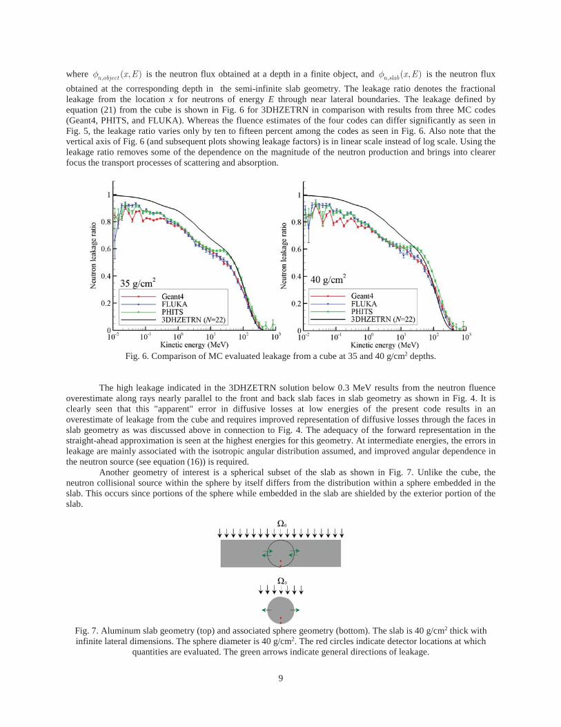
where , ( , )n object x E is the neutron flux obtained at a depth in a finite object, and , ( , )n slab x E is the neutron flux obtained at the corresponding depth in the semi-infinite slab geometry. The leakage ratio denotes the fractional leakage from the location x for neutrons of energy E through near lateral boundaries. The leakage defined by equation (21) from the cube is shown in Fig. 6 for 3DHZETRN in comparison with results from three MC codes (Geant4, PHITS, and FLUKA). Whereas the fluence estimates of the four codes can differ significantly as seen in Fig. 5, the leakage ratio varies only by ten to fifteen percent among the codes as seen in Fig. 6. Also note that the vertical axis of Fig. 6 (and subsequent plots showing leakage factors) is in linear scale instead of log scale. Using the leakage ratio removes some of the dependence on the magnitude of the neutron production and brings into clearer focus the transport processes of scattering and absorption.
Fig. 6. Comparison of MC evaluated leakage from a cube at 35 and 40 g/cm2 depths.
The high leakage indicated in the 3DHZETRN solution below 0.3 MeV results from the neutron fluence overestimate along rays nearly parallel to the front and back slab faces in slab geometry as shown in Fig. 4. It is clearly seen that this "apparent" error in diffusive losses at low energies of the present code results in an overestimate of leakage from the cube and requires improved representation of diffusive losses through the faces in slab geometry as was discussed above in connection to Fig. 4. The adequacy of the forward representation in the straight-ahead approximation is seen at the highest energies for this geometry. At intermediate energies, the errors in leakage are mainly associated with the isotropic angular distribution assumed, and improved angular dependence in the neutron source (see equation (16)) is required.
Another geometry of interest is a spherical subset of the slab as shown in Fig. 7. Unlike the cube, the neutron collisional source within the sphere by itself differs from the distribution within a sphere embedded in the slab. This occurs since portions of the sphere while embedded in the slab are shielded by the exterior portion of the slab.
Fig. 7. Aluminum slab geometry (top) and associated sphere geometry (bottom). The slab is 40 g/cm2 thick with infinite lateral dimensions. The sphere diameter is 40 g/cm2. The red circles indicate detector locations at which
quantities are evaluated. The green arrows indicate general directions of leakage.
9

While leakage effects from the cube are unambiguous, leakage from the sphere is obscured by the differences in the neutron source distribution; still, leakage as defined by equation (21) remains a useful concept. The neutron source distributions for energies above 1 MeV in the cube and sphere are shown in Fig. 8. The calculated neutron fluence at 35 and 40 g/cm2 from the present method is shown in comparison with that of the three MC codes in Fig. 9. It is first noted that the current solution method is in better agreement with the MC codes in spherical geometry as seen in comparing Fig. 9 with Fig. 5.
Fig. 8. Isotropic neutron source (E > 1 MeV) distribution in units of neutrons/(g-event) induced by the Webber SPE
spectrum in cube and spherical geometry.
Fig. 9. Particle spectra at detector locations 35 g/cm2 (left pane) and 40 g/cm2 from top of aluminum sphere
(diameter 40 g/cm2) exposed to Webber SPE spectrum.
The results of the present calculation for leakage at 35 and 40 g/cm2 within the sphere are shown in comparison with results from the three MC codes in Fig. 10. All of the codes have differences in nuclear models (the HZETRN models are discussed in Wilson et al. [1991], and the MC models are discussed in Appendix A of Wilson et al. [2014a,b]). Differing nuclear models are the main source of differences observed in Fig. 10. The present calculation uses the straight-ahead approximation for the forward components at the highest energies for which no lateral leakage occurs and is the primary source of leakage differences between the cube (Fig. 6) and the sphere (Fig. 10) above 100 MeV [Wilson et al. 2014a,b]. Clearly the straight-ahead approximation is more appropriate along the
10

central ray of the cube and less appropriate in the sphere. The overestimate of leakage below 0.3 MeV follows from errors in diffusion through the slab faces along rays parallel (or nearly parallel) to the facial plane. Improved treatment of the nuclear models below 10 MeV, where quasi-elastic scattering is negligible, and above 100 MeV, where the assumed straight-ahead approximation introduces error, will require formal improvements to the present calculations.
Fig. 10. Comparison of MC evaluated leakage from a sphere at 35 and 40 g/cm2 depths.
To further examine 3D effects, the leakage of the cube and sphere in the present code is compared with MC codes that have better representation of low energy scattering and the high-energy angular dependent cross sections (relative to the straight-ahead approximation used herein). MC (Geant4, FLUKA, PHITS) and 3DHZETRN derived results are shown in Figs. 5, 6, 9-14. Whereas good agreement of the leakage factor for the cube above 100 MeV is obtained (see Fig. 6), the failure of the straight-ahead approximation in the sphere is apparent in Fig. 10. Note that the leakage of the sphere exceeds that of the cube in the present formalism and that the main differences are above 100 MeV. The source of this high-energy difference results from the slight angular divergence from the forward direction that is of less importance along the cube centerline compared with leakage along the centerline of the sphere.
Fig. 11. Leakage factors for cube and sphere at 35 g/cm2 and 40 g/cm2 evaluated by the 3DHZETRN (N = 22) code.
11

Surprisingly, the leakage factor for the cube and sphere are largely similar in the 3DHZETRN formalism as seen in Fig. 11. Hence, the geometric shape in this case has only modest effects in the present formalism within similar sized objects. This is an advantage in that the neutron spectrum depends weakly on geometric detail. An interesting feature of the present formalism is that the cube exhibits greater leakage than the sphere at intermediate energies (1 to 100 MeV). This results from the isotropic source term which has the same distribution in the cube but is significantly modified in the sphere as shown in Fig. 8 and places the intense neutron source region closer to the detectors and hence appears as reduced leakage as defined by equation (21).
This weak dependence on geometry is somewhat borne out in the Geant4 results shown in Fig. 12, except that the sphere exhibits greater leakage as intuition would suggest. The greater leakage expected for the sphere above 100 MeV is likewise given by the Geant4 code. Similar results are found for the PHITS code as seen in comparing Fig. 13 with Fig. 12. A surprising result of the present benchmark is the results from the FLUKA code seen in Fig. 14. Although the excess leakage in the sphere above 100 MeV is clearly due to the straight-ahead approximation, the intermediate energy excess leakage is due to the differences within the FLUKA nuclear model.
Fig. 12. Leakage factors for cube and sphere at 35 g/cm2 and 40 g/cm2 evaluated by the Geant4 MC code.
Fig. 13. Leakage factors for cube and sphere at 35 g/cm2 and 40 g/cm2 evaluated by the PHITS MC code.
12

Fig. 14. Leakage factors for cube and sphere at 35 g/cm2 and 40 g/cm2 evaluated by the FLUKA MC code.
It is clear from the above results that improvements in the transport model in which the first order scattering angular dependence is treated as an isotropic source lies in the following: the low energy transport requires higher order corrections to scattering, and the isotropic source contributions need to be expanded to include more complex angular factors extending up to higher energies than currently represented. Further complications are added in solving the Boltzmann equation in inhomogeneous objects. The next section examines inhomogeneity in a tissue sphere shielded by aluminum. Simple Inhomogeneous Geometry
In this section, simple inhomogeneous slab geometry is considered by substituting a 30 cm (30 g/cm2) thick layer of ICRU tissue [ICRU 1993] within 7.41 cm (20 g/cm2) of aluminum shielding above and below. The cube subset becomes a box of 44.82 cm on each side. Both geometries are shown in Fig. 15. The alternate spherical geometry will consist of an ICRU tissue equivalent sphere (30 cm diameter) surrounded by an aluminum shell with thickness 7.41 cm (20 g/cm2). As in the case of the homogeneous configurations, convergence of the neutron fluence in the slab is considered first; with exposure of this arrangement from above by the Webber SPE. Results are shown in Fig. 16.
Fig. 15. Slab geometry (top) and associated cube geometry (bottom). The slab is 30 g/cm2 (30 cm) of ICRU tissue
with 20 g/cm2 (7.41 cm) of aluminum above and below and infinite lateral dimensions. The cube has the same thickness of ICRU tissue and aluminum and has lateral dimensions of 44.82 cm. The red circles indicate detector
locations at which quantities are evaluated. The green arrows indicate general directions of leakage.
13

Fig. 16. Convergence test in an inhomogeneous slab composed of a 30 cm ICRU tissue slab shielded above and
below by 7.41 cm of aluminum exposed to the Webber SPE spectrum. Results shown at 0 cm (left pane) and 30 cm (right pane), corresponding to the top and bottom detector locations, as shown in Fig. 15, respectively.
The E >1 MeV isotropic neutron source for the rectangular box and shielded sphere (discussed later in this report) are shown in Fig. 17. One sees clearly that the cube neutron source is distributed along the z-axis as one would expect for the slab configuration. The abrupt change in crossing from the aluminum shield into tissue is clearly seen near the top interface. A similar transition occurs at the top of the tissue sphere as well. The calculated neutron fluence generated in the inhomogeneous cube derived from the 3DHZETRN and MC codes is shown in Fig. 18. Note that the 3DHZETRN tends to have good overall agreement with the MC (Geant4, PHITS, FLUKA) codes at least to the extent the MC codes agree among themselves. The neutron leakage as seen from the detector locations on both the top and bottom of the tissue phantom is shown in Fig. 19 as evaluated by 3DHZETRN and MC codes. Unlike leakage from the uniform aluminum cube, the tissue phantom of the inhomogeneous cube provides significant absorption so that neutron leakage is limited. In this case, there is reasonable agreement between 3DHZETRN and the MC simulations.
Fig. 17. Isotropic neutron source (E > 1 MeV) distribution in units of neutrons/(g-event) induced by the Webber SPE
in the rectangular box and shielded sphere. The intensity (color) scale has been adjusted to more clearly show the shadow cast by the tissue sphere.
14

Fig. 18. Particle spectra at detector locations 0 cm (left pane) and 30 cm (right pane) from top of the tissue box
(thickness 30 cm) shielded by aluminum above and below (thickness 7.41 cm) exposed to the Webber SPE spectrum.
Fig. 19. Leakage from an inhomogeneous cube of aluminum/tissue/aluminum as seen at the center of the top
interface (x = 0) and the lower interface (x = 30).
Consider now a 30 cm diameter ICRU tissue sphere shielded by a 7.41 cm spherical shell of aluminum, as shown in Fig. 20. The change in calculation due to the inhomogeneity is that the penetration depth must evaluate the aluminum depth separate from the depth in the tissue sphere, and the solution along any direction i will include propagation thru both media from the outer limits of the object along the ray i to the evaluation point. In this example, the solution for neutron fluence is evaluated at the top and bottom of the ICRU sphere that serves in this work as proxy for the astronaut (ICRU phantom, see ICRU [1993] and Wilson et al. [2014c, 2015]). The neutron fluence is evaluated in the tissue and aluminum interface at the top and bottom of the tissue sphere using both 3DHZETRN and MC methods (Geant4, PHITS, and FLUKA). In order to control statistical fluctuations, the MC simulations require a relatively large volume over which fluences are scored. This implicitly integrates physical variations found locally near the detector volumes. To provide a consistent comparison, the 3DHZETRN fluence is obtained as an average of point results over the same volume (a sphere of 0.25 cm radius). The neutron fluence at top and bottom of the tissue sphere are shown in Fig. 21 where reasonable agreement with MC results are obtained. The corresponding neutron leakage ratio is shown in Fig. 22.
15

Fig. 20. Slab geometry (top) and associated sphere geometry (bottom). The slab is 30 g/cm2 (30 cm) of ICRU tissue with 20 g/cm2 (7.41 cm) of aluminum above and below and infinite lateral dimensions. The sphere is an ICRU tissue
sphere with diameter 30 g/cm2 (30 cm) surrounded by 20 g/cm2 (7.41 cm) aluminum. The red circles indicate detector locations at which quantities are evaluated. The green arrows indicate general directions of leakage.
Fig. 21. Particle spectra at detector locations 0 cm (left pane) and 30 cm (right pane) from top of tissue sphere (radius 15 cm) surrounded by an aluminum shell (thickness 7.41 cm) exposed from above by the Webber SPE
spectrum. Conclusions
The focus of the present study was neutron production and propagation. It was shown that the neutron differential fluence solution above 1 MeV in slab geometry converges well to match the Geant4 simulation in homogeneous materials. At lower energies, an error is introduced by the bi-directional approximation (N = 2) that assumes no additional diffusive losses for the propagation of the isotropic neutron component. The losses through the slab faces in transport along rays that are parallel or nearly parallel to the slab faces are underestimated (assumed zero). As a result, the neutron leakage ratio for the sphere and box is overestimated at low energies. A correction for losses along these long paths near lateral boundaries is required. The convergence for solution in the slab geometry is greatly improved when a highly absorptive tissue layer is introduced as an inhomogeneous layer. Above 100 MeV, the 3DHZETRN generally underestimates the leakage due the straight-ahead assumption and is easily seen in the neutron leakage ratio of the sphere where angular divergence is expected to play an important role. On the centerline of the cube, the straight-ahead approximation is more correct. These errors will be partly corrected by treating the angular dependence in greater detail.
16

Fig. 22. Leakage from an inhomogeneous sphere of aluminum/tissue at the top interface (left pane) and lower
interface (right pane).
The codes for space design are still incomplete in both the physical description and the corresponding implementation of the computational procedures. Even so, the current development is state-of-the-art in computational procedures for spacecraft design. The present version of 3DHZETRN has some inherent limitations (aside from the simplified geometry) that carry over from the forward/backward transport methods in which the main share of light ions are still treated in the straight-ahead approximation as coupled to the forward propagating neutrons. Only the "assumed" isotropically produced neutrons are first transported in 3D without the coupling to the isotropically produced light ion components. Once the isotropically produced neutrons are evaluated, the final coupling to the light ions is implemented (without further nuclear reactions) in a full 3D manner. Hence, only a fraction of the light ions have a 3D treatment resulting in transport effects of unquantified magnitude. Future work will require extension to complex geometries and treatment of the cross-coupling of 3D neutron/light ion transport. Nonetheless, the present expanded treatment of 3D effects show great promise in the path to a fully 3D transport algorithm. Acknowledgements This work was supported by the Human Research Program under the Human Exploration and Operations Mission Directorate of NASA and by NASA Grant number NNX09AR20A. References Agostinelli, S. et al., Geant4--a simulation toolkit. Nucl. Instrum. & Methods A 506: 250-303; 2003. Alsmiller, R.G., Irving, D.C., Kinney, W.E., Moran, H.S. The validity of the straightahead approximation in space vehicle shielding studies. In Second Symposium on Protection Against Radiations in Space, Arthur Reetz, ed. NASA SP-71, pp. 177-181, 1965. Alsmiller, R.G., Personal communication, 1967. Battistoni, G., Muraro, S., Sala, P.R., Cerutti, F., Ferrari, A., Roesler, S.,Fasso, A., Ranft, J., The FLUKA code: Description and benchmarking. Proceedings of the Hadronic Shower Simulation Workshop 2006, 896: 31–49; 2007. Blattnig, S.R., Norbury, J.W., Norman, R.B., Wilson, J.W., Singleterry, R.C., Tripathi, R.K., MESTRN: A Deterministic meson-muon transport code for space radiation. NASA TM-212995, 2004. Clowdsley, M.S., et al. A comparison of the multigroup and collocation methods for solving the low energy neutron Boltzmann equation. Can. J. Phys. 78: 45-56; 2000.
17

Clowdsley, M.S., Wilson, J.W., Shinn, J.L., Badavi, F.F., Heinbockel, J.H., Atwell, W., Neutron environment calculations for low Earth orbit. SAE 01ICES2327, 2001. Cucinotta, F.A, Calculations of cosmic-ray helium transport in shielding materials. NASA TP-3354, 1993. Ersmark, T., Carlson, P., Daly, E., Christer Fuglesang, C., Gudowska, I., Lund-Jensen, B., Nieminen, P., Pearce, M., Santin, G.G., Geant4 Monte Carlo simulations of the belt proton radiation environment on board the International Space Station/Columbus. IEEE Transactions on Nuclear Science 54: 1444-1453; 2007. Fasso, A., Ferrari, A., Ranft, J., Sala, P.R., FLUKA: A multi-particle transport code, CERN-2005-10, INFN/TC 05/11, SLAC-R-773, 2005. Foelsche, T., Mendell, R.B., Wilson, J.W., Adams, R.R., Measured and calculated neutron spectra and dose equivalent rates at high altitudes: Relevance to SST operations and space research. NASA TN-D-7715, 1974. Ganapol, B.D., Townsend, L.W., Lamkin, S.L., Wilson, J.W., Benchmark solution for the galactic heavy ion transport equations with energy and spatial coupling. NASA TP-3112, 1991. Heinbockel, J.H., Feldman, G.A., Wilson, J.W., Singleterry, R.C., Leakeas, C.L., Clowdsley, M.S., Solutions to the low energy neutron Boltzmann equation for space applications. SAE 03ICES339, 2003. Heinbockel, J.H., Slaba, T.C., Blattnig, S.R., Tripathi, R.K., Townsend, L.W., Handler, T., Gabriel, T.A., Pinsky, L.S., Reddell, B., Clowdsley, M.S., Singleterry, R.C., Norbury, J.W., Badavi, F.F., Aghara, S.K., Comparison of the transport codes HZETRN, HETC and FLUKA for a solar particle event. Adv. Space Res. 47: 1079-1088; 2011a. Heinbockel, J.H., Slaba, T.C., Tripathi, R.K., Blattnig, S.R., Norbury, J.W., Badavi, F.F., Townsend, L.W., Handler, T., Gabriel, T.A., Pinsky, L.S., Reddell, B., Aumann, A.R., Comparison of the transport codes HZETRN, HETC and FLUKA for galactic cosmic rays. Adv. Space Res. 47:1089-1105; 2011b. ICRU Internal Commission on Radiation Units and Measurements, Quantities and Units in Radiation Protection Dosimetry, ICRU Report 51, 1993. Lambiotte, J.J., Wilson, J.W., Filippas, T.A., PROPER3C: A nucleon-pion transport code. NASA TM-2158, 1971. Lamkin, S.L., A theory for high-energy nucleon transport in one-dimension. MS Thesis, Old Dominion University, June 1974. Lamkin, S.L., High energy coupled nucleon transport in one dimension. PhD Dissertation, Old Dominion University, April 1994. Norman, R.B., Blattnig, S.R., De Angelis, G., Badavi, F.F., Norbury, J.W., Deterministic pion and muon transport in Earth’s atmosphere. Adv. Space Res. 50: 146-155; 2012. Norman, R.B., Slaba, T.C., Blattnig, S.R., An extension of HZETRN for cosmic ray initiated electromagnetic cascades. Adv. Space Res. 51: 2251-2260; 2013. Sato, T., Niita, K., Iwase, H., Nakashima, H., Yamaguchi, Y., Sihver, L., Applicability of particle and heavy ion transport code PHITS to the shielding design of spacecrafts, Rad. Meas., 41: 1142 – 1146; 2006. Sato, T., Niita, K., Matsuda, N., Hashimoto, S., Iwamoto, Y., Noda, S., Ogawa, T., Iwase, H.,Nakashima, H., Fukahori, T., Okumura, K., Kai, T., Chiba, S., Furuta T., Sihver, L., Particle and heavy ion transport code system PHITS, version 2.52, J. Nucl. Sci. Technol. 50: 913-923; 2013. Shavers, M. R., Curtis, S.B., Miller, J., Schimmerling, W., The fragmentation of 670A MeV Neon-20 as a function of depth in water. II. One-generation transport theory. Rad. Res. 124: 117-130; 1990.
18

Shavers, M. R., Frankel, K., Miller, J., Schimmerling, W., Townsend, L. W., Wilson, J. W., The fragmentation of 670 A MeV Neon-20 as a function of depth in water. III. Analytic multigeneration transport Theory. Rad. Res., 134: 1-14; 1993. Shinn, J.L., Cucinotta, F.A., Simonsen, L.C., Wilson, J.W., Badavi, F.F., Badhwar, G.D., Miller, J., Zeitlin, C., Heilbronn, L., Tripathi, R.K., Clowdsley, M.S., Heinbockel, J.H., Xapsos, M.A., Validation of a comprehensive space radiation transport code. IEEE Transactions on Nuclear Science 45: 2711-2719; 1998. Slaba, T.C., Blattnig, S.R., Badavi, F.F., Faster and more accurate transport procedures for HZETRN. J. Comp. Phys. 229: 9397-9417; 2010a. Slaba, T.C., Blattnig, S.R., Aghara, S.K., Townsend, L.W., Handler, T., Gabriel, T.A., Pinsky, L.S., Reddell, B., Coupled neutron transport for HZETRN. Rad. Meas. 45: 173-182; 2010b. Slaba, T.C., Blattnig, S.R., Clowdsley, M.S., Variations in lunar neutron dose estimates. Rad. Res. 176: 827-841; 2011. Slaba, T.C., Blattnig, S.R., Reddell, B., Bahadori, A., Norman, R.B., Badavi, F.F., Pion and electromagnetic contribution to dose: Comparisons of HZETRN to Monte Carlo results and ISS data. Adv. Space Res. 52: 62-78; 2013. Tweed, J., Walker, S.A., Wilson, J.W., Cucinotta, F.A., Tripathi, R.K., Blattnig, S., Mertens, C.J. Computational methods for the HZETRN code. Adv. Space Res. 35:194-201; 2006a. Tweed, J., Walker, S.A., Wilson, J.W., Tripathi, R.K., Cucinotta, F.A., Badavi, F.F., An improved Green's function code for HZE transport. ICES SAE 2006-01-2147, 2006b. Webber, W.R., An evaluation of solar-cosmic-ray events during solar minimum. D2-84274-1, Boeing Co., 1966. Wilson, J.W. and Lamkin, S.L. Perturbation approximation to charged particle transport. Trans. Am. Soc., 19: 443; 1974. Wilson, J.W. and Khandelwal, G.S., Proton dose approximation in convex geometry. Nucl. Tech. 23: 298-305;1974. Wilson, J.W. and Lamkin, S.L., Perturbation theory for charged-particle transport in one dimension. Nucl. Sci. & Eng. 57(4): 292-299; 1975. Wilson, J.W., Analysis of the theory of high-energy ion transport. NASA TN-D-8381, 1977. Wilson, J.W., Townsend, L.W., Bidasaria, H.B., Schimmerling, W., Wong, M. Howard, J., 20-Ne depth-dose relations in water. Health Phys. 46: 1101-1111; 1984. Wilson, J. W. and Badavi, F. F., Methods of galactic heavy ion transport. Rad. Res. 108: 231-237; 1986. Wilson, J. W., Townsend, L. W., Badavi, F. F., A semiempirical nuclear fragmentation model. Nucl. Inst. & Methods B 18: 225; 1987a. Wilson, J. W., Townsend, L. W., Badavi, F. F., Galactic cosmic ray propagation in earth's atmosphere. Rad. Res. 109: 173-183; 1987b. Wilson, J.W., Chun, S.Y., Buck, W.W., Townsend, L.W., BRYNTRN, a baryon transport computer code: computation procedures and data base. NASA TM-4037, 1988a. Wilson, J.W., Chun, S.Y., Buck, W.W., Townsend, L.W., High energy nucleon data bases. Health Phys., 55: 817-819; 1988b.
19

Wilson, J.W., Townsend, L.W., Schimmerling, W., Khandelwal, G.S., Khan, F., Nealy, J.E., Cucinotta, F.A., Simonsen, L.C., Shinn, J.L., Norbury, J.W., Transport methods and interactions for space radiations. NASA RP-1257, 1991. Wilson, J.W., Tripathi, R.K., Cucinotta, F.A., Shinn, J.L., Badavi, F.F., Chun, S.Y., Norbury, J.W., Zeitlin, C.J., Heilbronn, L. H., Miller, J., NUCFRG2, An evaluation of the semiempirical nuclear fragmentation database, NASA TP-3533, 1995. Wilson, J. W., Cucinotta, F. A., Tai, H., Shinn, J. L., Chun, S. Y., Tripathi, R.K., Sihver, L., Transport of light ions in matter. Adv. Space Res. 21: 1763-1771; 1998. Wilson, J.W., Cucinotta, F.A., Schimmerling, W.S., Emerging radiation health-risk mitigation technologies. AIP Conf. Proc. 699: 913-924; 2004. Wilson, J.W., Tripathi, R.K., Mertens, C.J., Blattnig, S.R., Clowdsley, M.S., Verification and validation: High charge and energy (HZE) transport codes and future development. NASA TP-2005-213784, 2005. Wilson, J.W., Slaba, T.C., Badavi, F.F., Reddell, B.D., Bahadori, A.A., A 3DHZETRN code in a spherical uniform sphere with Monte Carlo verification. NASA TP-2014-218271, 2014a. Wilson, J.W., Slaba, T.C., Badavi, F.F., Reddell, B.D., Bahadori, A.A., Advances in NASA space radiation research: 3DHZETRN, Life Sci. Space Res. 2: 6-22; 2014b. Wilson, J.W., Slaba, T.C., Badavi, F.F., Reddell, B.D., Bahadori, A.A., 3D space radiation transport in a shielded ICRU tissue sphere. NASA TP-2014-218530, 2014c. Wilson, J.W., Slaba, T.C., Badavi, F.F., Reddell, B.D., Bahadori, A.A., 3DHZETRN: Shielded ICRU spherical phantom, Life Sci. Space Res. 4: 46-61; 2015. Wright, H.A., Personal communication, 1966. Wright, H.A., Anderson, V.E., Turner, J.E., Neufield, J., Snyder, W.S., Calculation of radiation dose due to protons and neutrons with energies 0.4 to 2.4 GeV. Health Physics 16: 13; 1969.
20

REPORT DOCUMENTATION PAGE Form ApprovedOMB No. 0704-0188
2. REPORT TYPE
4. TITLE AND SUBTITLE 5a. CONTRACT NUMBER
6. AUTHOR(S)
7. PERFORMING ORGANIZATION NAME(S) AND ADDRESS(ES)
9. SPONSORING/MONITORING AGENCY NAME(S) AND ADDRESS(ES)
8. PERFORMING ORGANIZATION REPORT NUMBER
10. SPONSOR/MONITOR'S ACRONYM(S)
13. SUPPLEMENTARY NOTES
12. DISTRIBUTION/AVAILABILITY STATEMENT
19a. NAME OF RESPONSIBLE PERSON
14. ABSTRACT
15. SUBJECT TERMS
18. NUMBER OF PAGES
19b. TELEPHONE NUMBER (Include area code)a. REPORT c. THIS PAGEb. ABSTRACT
17. LIMITATION OF ABSTRACT
Prescribed by ANSI Std. Z39.18Standard Form 298 (Rev. 8-98)
3. DATES COVERED (From - To)
5b. GRANT NUMBER
5c. PROGRAM ELEMENT NUMBER
5d. PROJECT NUMBER
5e. TASK NUMBER
5f. WORK UNIT NUMBER
11. SPONSOR/MONITOR'S REPORT NUMBER(S)
16. SECURITY CLASSIFICATION OF:
The public reporting burden for this collection of information is estimated to average 1 hour per response, including the time for reviewing instructions, searching existing data sources, gathering and maintaining the data needed, and completing and reviewing the collection of information. Send comments regarding this burden estimate or any other aspect of this collection of information, including suggestions for reducing this burden, to Department of Defense, Washington Headquarters Services, Directorate for Information Operations and Reports (0704-0188), 1215 Jefferson Davis Highway, Suite 1204, Arlington, VA 22202-4302. Respondents should be aware that notwithstanding any other provision of law, no person shall be subject to any penalty for failing to comply with a collection of information if it does not display a currently valid OMB control number.PLEASE DO NOT RETURN YOUR FORM TO THE ABOVE ADDRESS.
1. REPORT DATE (DD-MM-YYYY)