Embed Size (px)
Citation preview

3G TS 33.102 V3.2.0 (1999-10)Technical Specification
3rd Generation Partnership Project;Technical Specification Group Services and System Aspects;
3G Security;Security Architecture
(3G TS 33.102 version 3.2.0)
The present document has been developed within the 3rd Generation Partnership Project (3GPP TM) and may be further elaborated for the purposes of 3GPP. The present document has not been subject to any approval process by the 3GPP Organisational Partners and shall not be implemented. This Specification is provided for future development work within 3GPP only. The Organisational Partners accept no liability for any use of this Specification. Specifications and reports for implementation of the 3GPP TM system should be obtained via the 3GPP Organisational Partners' Publications Offices.

3GPP
3G TS 33.102 V3.2.0 (1999-10)23G TS 33.102 version 3.2.0
Reference DTS/TSGS-0333102U
Keywords Security, Architecture
3GPP
Postal address
3GPP support office address 650 Route des Lucioles - Sophia Antipolis
Valbonne - FRANCE Tel.: +33 4 92 94 42 00 Fax: +33 4 93 65 47 16
Internet http://www.3gpp.org

3GPP
3G TS 33.102 V3.2.0 (1999-10)33G TS 33.102 version 3.2.0
Contents
Foreword ................................................................................................................................................6
1 Scope ............................................................................................................................................7
2 References ....................................................................................................................................7 2.1 Normative references........................................................................................................................................................... 7 2.2 Informative references......................................................................................................................................................... 8
4 Overview of the security architecture ............................................................................................10
5 Security features ..........................................................................................................................11 5.1 Network access security................................................................................................................................................... 11 5.1.1 User identity confidentiality ...................................................................................................................................... 11 5.1.2 Entity authentication................................................................................................................................................... 11 5.1.3 Confidentiality.............................................................................................................................................................. 12 5.1.4 Data integrity................................................................................................................................................................ 12 5.1.5 Mobile equipment identification ............................................................................................................................... 12 5.2 Network domain security.................................................................................................................................................. 13 5.2.1 Entity authentication................................................................................................................................................... 13 5.2.2 Data confidentiality..................................................................................................................................................... 13 5.2.3 Data integrity................................................................................................................................................................ 13 5.2.4 Fraud information gathering system......................................................................................................................... 14 5.3 User domain security......................................................................................................................................................... 14 5.3.1 User-to-USIM authentication.................................................................................................................................... 14 5.3.2 USIM-Terminal Link.................................................................................................................................................... 14 5.4 Application security.......................................................................................................................................................... 14 5.4.1 Secure messaging between the USIM and the network........................................................................................ 14 5.4.2 Network-wide user traffic confidentiality................................................................................................................. 15 5.4.3 Access to user profile data ........................................................................................................................................ 15 5.4.4 IP security..................................................................................................................................................................... 15 5.5 Security visibility and configurability............................................................................................................................. 15 5.5.1 Visibility ....................................................................................................................................................................... 15 5.5.2 Configurability ............................................................................................................................................................. 15
6 Network access security mechanisms............................................................................................16 6.1 Identification by temporary identities............................................................................................................................. 16 6.1.1 General........................................................................................................................................................................... 16 6.1.2 TMUI reallocation procedure .................................................................................................................................... 16 6.1.3 Unacknowledged allocation of a temporary identity ............................................................................................. 16 6.1.4 Location update........................................................................................................................................................... 17 6.2 Identification by a permanent identity............................................................................................................................ 17 6.3 Authentication and key agreement................................................................................................................................. 18 6.3.1 General........................................................................................................................................................................... 18 6.3.2 Distribution of authentication data from HE to SN ................................................................................................ 20 6.3.3 Authentication and key agreement........................................................................................................................... 22 6.3.3.1 Cipher key selection .......................................................................................................................................................... 24 6.3.3.1.1 User plane......................................................................................................................................................... 25 6.3.3.1.2 Control plane.................................................................................................................................................... 25 6.3.4 Distribution of authentication vectors between VLRs .......................................................................................... 25 6.3.5 Re-synchronisation procedure .................................................................................................................................. 25 6.3.6 Length of sequence numbers .................................................................................................................................... 26 6.3.7 Support for window and list mechanisms ................................................................................................................ 27 6.4.1 Cipher key and integrity key setting......................................................................................................................... 27 6.4.2 Cipher key and integrity mode negotiation ............................................................................................................. 27 6.4.3 Cipher key and integrity key lifetime ........................................................................................................................ 28 6.4.4 Cipher key and integrity key identification.............................................................................................................. 28

3GPP
3G TS 33.102 V3.2.0 (1999-10)43G TS 33.102 version 3.2.0
6.4.5 Security mode set-up procedure ............................................................................................................................... 28 Signalling procedures in the case of an unsuccessful integrity check......................................................................................... 30 6.5.1 General........................................................................................................................................................................... 31 6.5.2 Integrity algorithm....................................................................................................................................................... 31 6.5.3 UIA identification....................................................................................................................................................... 32 6.6.1 General........................................................................................................................................................................... 32 6.6.2 Ciphering algorithm..................................................................................................................................................... 32 6.6.3 UEA identification....................................................................................................................................................... 32 6.6.4 Synchronisation of ciphering .................................................................................................................................... 33 6.6.4.1 Layer for ciphering................................................................................................................................................ 33 6.6.4.2 Handover ...................................................................................................................................................................... 33 6.7.1 Introduction.................................................................................................................................................................. 34 6.7.2 Ciphering method ........................................................................................................................................................ 34 6.7.3 Key management ......................................................................................................................................................... 35 6.7.3.1 General case........................................................................................................................................................... 35 6.7.3.2 Outline scheme for intra-serving network case................................................................................................ 36 6.7.3.3 Variant on the outline scheme ............................................................................................................................. 37 6.8.1 Interoperability for UMTS users ............................................................................................................................... 37 6.8.2 Interoperability for GSM users .................................................................................................................................. 39
7 Network domain security mechanisms ...........................................................................................41 7.1 Overview of Mechanism................................................................................................................................................... 41 7.1.1 Layer I............................................................................................................................................................................ 41 7.1.2 Layer II .......................................................................................................................................................................... 42 7.1.3 Layer III......................................................................................................................................................................... 42 7.1.4 General Overview......................................................................................................................................................... 42 7.2 Layer I Message Format ................................................................................................................................................... 43 7.2.1 Properties and Tasks of Key Administration Centres ........................................................................................... 43 7.2.2 Transport of Session Keys ........................................................................................................................................ 44 7.3 Layer II Message Format.................................................................................................................................................. 44 7.4 Layer III Message Format................................................................................................................................................. 45 7.4.1 General Structure of Layer III Messages ................................................................................................................. 45 7.4.2 Format of Layer III Message Body........................................................................................................................... 46 7.4.2.1 Protection Mode 0................................................................................................................................................. 46 7.4.2.2 Protection Mode 1................................................................................................................................................. 46 7.4.2.3 Protection Mode 2................................................................................................................................................. 46 7.5 Mapping of MAP Messages and Modes of Protection.............................................................................................. 47
8 Application security mechanisms ...................................................................................................47 8.1 Secure messaging between the USIM and the network .............................................................................................. 47 8.2.1 Introduction.................................................................................................................................................................. 47 8.2.2 Ciphering method ........................................................................................................................................................ 48 8.2.3 Key management ......................................................................................................................................................... 49 8.3 IP security ........................................................................................................................................................................... 50
Annex A: Requirements analysis.............................................................................................................51
Annex B (Informative): Enhanced user identity confidentiality...................................................................52
Annex C: Management of sequence numbers ..........................................................................................53
C.1 A mechanism using two individual counters on each side.................................................................53
C.2 A mechanism using a global counter in the HE and two counters in the MS......................................53 C.5 A mechanism using two individual counters on each side offering protection against wrap around of
counters ............................................................................................................................................................................... 54
Annex D: A mechanism for authentication based on a temporary key........................................................56
D.1 Authentication based on a Temporary Key.....................................................................................56 D.1.1 General................................................................................................................................................................................. 56 D.1.2 Temporary Key Generation with Session Key Agreement.......................................................................................... 57

3GPP
3G TS 33.102 V3.2.0 (1999-10)53G TS 33.102 version 3.2.0
D.1.3 Distribution of temporary keys between VLRs ............................................................................................................. 60 D.1.4 Handover............................................................................................................................................................................. 60
D.2 Local authentication......................................................................................................................61 D.2.1 Session Key Agreement based on Temporary Authentication Key ......................................................................... 61 D.3 Criteria for replacing the authentication “working assumption”................................................................................ 62
Annex E: A Proposal for Layer II Message Format.................................................................................63 E.1 Introduction........................................................................................................................................................................ 63 E.2 Proposed Layer II Message Format................................................................................................................................ 63 E.2.1 Sending a session key for decryption...................................................................................................................... 64 E.2.2 Sending a session key for encryption...................................................................................................................... 64
Annex F (Informative): Example uses of AMF ........................................................................................65 F.1 Support multiple authentication algorithms and keys.................................................................................................. 65 F.2 Changing the size of windows and lists ......................................................................................................................... 65 F.3 Handling authentication vectors from separate CS/PS domains using a MODE parameter.................................. 65
Annex G: Change history .................................................................................................................. 66
History..................................................................................................................................................67

3GPP
3G TS 33.102 V3.2.0 (1999-10)63G TS 33.102 version 3.2.0
Foreword This Technical Specification has been produced by the 3GPP.
The contents of the present document are subject to continuing work within the TSG and may change following formal TSG approval. Should the TSG modify the contents of this TS, it will be re-released by the TSG with an identifying change of release date and an increase in version number as follows:
Version 3.y.z
where:
x the first digit:
1 presented to TSG for information;
2 presented to TSG for approval;
3 Indicates TSG approved document under change control.
y the second digit is incremented for all changes of substance, i.e. technical enhancements, corrections, updates, etc.
z the third digit is incremented when editorial only changes have been incorporated in the specification.
3GPP
3G TS 33.102 V3.2.0 (1999-10)73G TS 33.102 version 3.2.0
1 Scope This specification defines the security architecture, i.e., the security features and the security mechanisms, for the third generation mobile telecommunication system.
A security feature is a service capabilities that meets one or several security requirements. The complete set of security features address the security requirements as they are defined in "3G Security: Threats and Requirements" (21.133 [1]). A security mechanism is an element that is used to realise a security feature. All security features and security requirements taken together form the security architecture.
An example of a security feature is user data confidentiality. A security mechanism that may be used to implement that feature is a stream cipher using a derived cipher key.
2 References The following documents contain provisions which, through reference in this text, constitute provisions of the present document.
• References are either specific (identified by date of publication, edition number, version number, etc.) or non-specific.
• For a specific reference, subsequent revisions do not apply.
• For a non-specific reference, the latest version applies.
2.1 Normative references
[1] 3G TS 21.133: "3rd Generation Partnership Project (3GPP); Technical Specification Group (TSG) SA; 3G Security; Security Threats and Requirements".
[2] 3G TS 33.120: "3rd Generation Partnership Project (3GPP); Technical Specification Group (TSG) SA; 3G Security; Security Principles and Objectives".
[3] UMTS 33.21, version 2.0.0: "Security requirements".
[4] UMTS 33.22, version 1.0.0: "Security features".
[5] UMTS 33.23, version 0.2.0: "Security architecture".
[6] Proposed UMTS Authentication Mechanism based on a Temporary Authentication Key.
[7] TTC Work Items for IMT-2000 – System Aspects.
[8] Annex 8 of "Requirements and Objectives for 3G Mobile Services and systems" – "Security Design Principles".
[9] ETSI GSM 09.02 Version 4.18.0: Mobile Application Part (MAP) Specification.
[10] ISO/IEC 11770-3: Key Management – Mechanisms using Asymmetric Techniques.
[11] ETSI SAGE: Specification of the BEANO encryption algorithm, Dec. 1995 (confidential).
[12] ETSI SMG10 WPB: SS7 Signalling Protocols Threat Analysis , Input Document AP 99-28 to SMG10 Meeting#28, Stockholm, Sweden.
[13] 3G TS 33.105: "3rd Generation Partnership Project (3GPP); Technical Specification Group (TSG) SA; 3G Security; Cryptographic Algorithm Requirements".

3GPP
3G TS 33.102 V3.2.0 (1999-10)83G TS 33.102 version 3.2.0
2.2 Informative references
GSM documents:
[14] GSM 02.09 version 5.1.1: "Security Aspects".
[15] GSM 02.22 version 6.0.0: "Personalisation of GSM Mobile Equipment (ME); Mobile functionality specification".
[16] GSM 02.48, version 6.0.0: "Security Mechanisms for the SIM Application Toolkit; Stage 1".
[17] GSM 02.60, version 7.0.0: "GPRS; Service Description; Stage 1".
[18] GSM 03.20, version 6.0.1: "Security related network functions".
[19] GSM 03.48, version 6.1.0; "Security Mechanisms for the SIM application toolkit; Stage 2".
[20] GSM 03.60, version 7.0.0: "GPRS; Service Description; Stage 2".
[21] GSM 11.11, version 7.1.0: "Specification of SIM-terminal interface".
[22] GSM 11.14, version 7.1.0: "Specification of SIM Application Toolkit for SIM-terminal interface".
UMTS documents:
[23] UMTS 21.11, version 0.4.0: "IC-card aspects".
[24] UMTS 23.01, version 1.0.0: "UMTS Network architecture".
[25] UMTS 23.20, version 1.4.0: "Evolution of the GSM platform towards UMTS".
3 Definitions, symbols and abbreviations
3.1 Definitions
For the purposes of the present document, the following definitions apply:
Confidentiality: The property that information is not made available or disclosed to unauthorised individuals, entities or processes.
Data integrity: The property that data has not been altered in an unauthorised manner.
Data origin authentication: The corroboration that the source of data received is as claimed.
Entity authentication: The provision of assurance of the claimed identity of an entity.
Key freshness: A key is fresh if it can be guaranteed to be new, as opposed to an old key being reused through actions of either an adversary or authorised party.
3.2 Symbols
For the purposes of the present document, the following symbols apply:
|| Concatenation ⊕ Exclusive or f1 Message authentication function used to compute MAC f2 Message authentication function used to compute RES and XRES f3 Key generating function used to compute CK f4 Key generating function used to compute IK f5 Key generating function used to compute AK
3GPP
3G TS 33.102 V3.2.0 (1999-10)93G TS 33.102 version 3.2.0
f6 Encryption function used to encrypt the IMUI f7 Decryption function used to decrypt the IMUI (=f6-1) K Long-term secret key shared between the USIM and the AuC
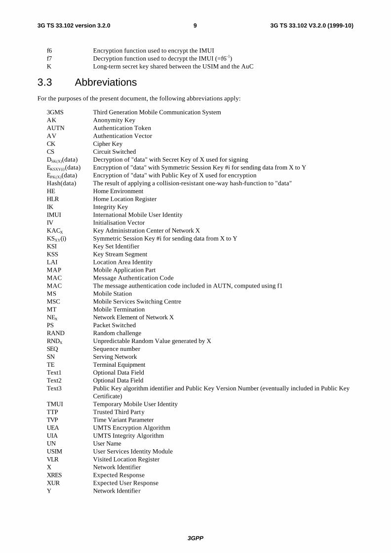
3.3 Abbreviations
For the purposes of the present document, the following abbreviations apply:
3GMS Third Generation Mobile Communication System AK Anonymity Key AUTN Authentication Token AV Authentication Vector CK Cipher Key CS Circuit Switched DSK(X)(data) Decryption of "data" with Secret Key of X used for signing EKSXY(i)(data) Encryption of "data" with Symmetric Session Key #i for sending data from X to Y EPK(X)(data) Encryption of "data" with Public Key of X used for encryption Hash(data) The result of applying a collision-resistant one-way hash-function to "data" HE Home Environment HLR Home Location Register IK Integrity Key IMUI International Mobile User Identity IV Initialisation Vector KACX Key Administration Center of Network X KSXY(i) Symmetric Session Key #i for sending data from X to Y KSI Key Set Identifier KSS Key Stream Segment LAI Location Area Identity MAP Mobile Application Part MAC Message Authentication Code MAC The message authentication code included in AUTN, computed using f1 MS Mobile Station MSC Mobile Services Switching Centre MT Mobile Termination NEX Network Element of Network X PS Packet Switched RAND Random challenge RNDX Unpredictable Random Value generated by X SEQ Sequence number SN Serving Network TE Terminal Equipment Text1 Optional Data Field Text2 Optional Data Field Text3 Public Key algorithm identifier and Public Key Version Number (eventually included in Public Key
Certificate) TMUI Temporary Mobile User Identity TTP Trusted Third Party TVP Time Variant Parameter UEA UMTS Encryption Algorithm UIA UMTS Integrity Algorithm UN User Name USIM User Services Identity Module VLR Visited Location Register X Network Identifier XRES Expected Response XUR Expected User Response Y Network Identifier

3GPP
3G TS 33.102 V3.2.0 (1999-10)103G TS 33.102 version 3.2.0
4 Overview of the security architecture Figure 1 gives an overview of the complete 3G security architecture.
Homestratum/ServingStratum
USIM HETE
Transportstratum
MT
SN
AN
Applicationstratum
User Application Provider Application(IV)
(III)
(II)
(I)
(I)
(I)
(I)
(I)
Figure 1 : Overview of the security architecture
Five security feature groups are defined. Each of these feature groups meets certain threats, accomplishes certain security objectives:
- Network access security (I): the set of security features that provide users with secure access to 3G services, and which in particular protect against attacks on the (radio) access link;
- Network domain security (II): the set of security features that enable nodes in the provider domain to securely exchange signalling data, and protect against attacks on the wireline network;
- User domain security (III): the set of security features that secure access to mobile stations
- Application domain security (IV): the set of security features that enable applications in the user and in the provider domain to securely exchange messages.
- Visibility and configurability of security (V): the set of features that enables the user to inform himself whether a security features is in operation or not and whether the use and provision of services should depend on the security feature.

3GPP
3G TS 33.102 V3.2.0 (1999-10)113G TS 33.102 version 3.2.0
5 Security features
5.1 Network access security
5.1.1 User identity confidentiality
The following security features related to user identity confidentiality are provided:
- user identity confidentiality: the property that the permanent user identity (IMUI) of a user to whom a services is delivered cannot be eavesdropped on the radio access link;
- user location confidentiality: the property that the presence or the arrival of a user in a certain area cannot be determined by eavesdropping on the radio access link;
- user untraceability: the property that an intruder cannot deduce whether different services are delivered to the same user by eavesdropping on the radio access link.
To achieve these objectives, the user is normally identified by a temporary identity by which he is known by the visited serving network, or by an encrypted permanent identity. To avoid user traceability, which may lead to the compromise of user identity confidentiality, the user should not be identified for a long period by means of the same temporary or encrypted identity. To achieve these security features, in addition it is required that any signalling or user data that might reveal the user’s identity is ciphered on the radio access link.
Clause 6.1 describes a mechanism that allows a user to be identified on the radio path by means of a temporary identity by which he is known in the visited serving network. This mechanism should normally be used to identify a user on the radio path in location update requests, service requests, detach requests, connection re-establishment requests, etc..
Clause 6.2 describes a mechanism that allows a user to be identified on the radio path in case he is not known in the visited serving network by a temporary identity. It provides a transparent channel between the USIM and the user’s HE that provides the user’s HE with the option to implement a mechanism that allows identification by means of an encrypted permanent identity. The serving network then has to forward the encrypted permanent identity to the user’s HE for decryption and receives the user’s permanent identity from the user’s HE. A possible mechanism that makes use of symmetric key encryption using group keys is included in Annex B. Alternatively, the user’s HE environment has the option to let the user identify himself by means of its permanent identity in cleartext. Either of both mechanisms should be used to identify a user on the radio path, whenever the user is not known by a temporary identity in the serving network.
5.1.2 Entity authentication
The following security features related to entity authentication are provided:
- authentication mechanism agreement: the property that the user and the serving network can securely negotiate the mechanism for authentication and key agreement that they shall use subsequently;
- user authentication: the property that the serving network corroborates the user identity of the user;
- network authentication: the property that the user corroborates that he is connected to a serving network that is authorised by the user’s HE to provide him services; this includes the guarantee that this authorisation is recent.
To achieve these objectives, it is assumed that entity authentication should occur at each connection set-up between the user and the network. Two mechanisms have been included: an authentication mechanism using an authentication vector delivered by the user’s HE to the serving network, and a local authentication mechanism using the integrity key established between the user and serving network during the previous execution of the authentication and key establishment procedure.

3GPP
3G TS 33.102 V3.2.0 (1999-10)123G TS 33.102 version 3.2.0
Clause 6.3 describes an authentication and key establishment mechanism that achieves the security features listed above and in addition establishes a secret cipher key (see 5.1.3) and integrity key (see 5.1.4) between the user and the serving network. This mechanism should be invoked by the serving network after a first registration of a user in a serving network and after a service request, location update request, attach request, detach request or connection re-establishment request, when the maximum number of local authentications using the derived integrity key have been conducted.
Clause 6.5 describes the local authentication mechanism. The local authentication mechanism achieves the security features user authentication and network authentication and uses an integrity key established between user and serving network during the previous execution of the authentication and key establishment procedure. This mechanism should be invoked by the serving network after a service request, location update request, attach request, detach request or connection re-establishment request, provided that the maximum number of local authentications using the same derived integrity key has not been reached yet.
5.1.3 Confidentiality
The following security features are provided with respect to confidentiality of data on the network access link:
- cipher algorithm agreement: the property that the MS and the SN can securely negotiate the algorithm that they shall use subsequently;
- cipher key agreement: the property that the MS and the SN agree on a cipher key that they may use subse-quently;
- confidentiality of user data: the property that user data cannot be overheard on the radio access interface;
- confidentiality of signalling data: the property that signalling data cannot be overheard on the radio access interface;
Cipher key agreement is realised in the course of the execution of the mechanism for authentication and key agreement (see 6.3). Cipher algorithm agreement is realised by means of a mechanism for security mode negotiation between the user and the network (see 6.6.9). This mechanism also enables the selected ciphering algorithm and the agreed cipher key to be applied in the way described in 6.6.
5.1.4 Data integrity
The following security features are provided with respect to integrity of data on the network access link:
- integrity algorithm agreement: the property that the MS and the SN can securely negotiate the integrity algorithm that they shall use subsequently;
- integrity key agreement: the property that the MS and the SN agree on an integrity key that they may use subsequently;
- data integrity and origin authentication of signalling data: the property that the receiving entity (MS or SN) is able to verify that signalling data has not been modified in an unauthorised way since it was sent by the sending entity (SN or MS) and that the data origin of the signalling data received is indeed the one claimed;
Integrity key agreement is realised in the course of the execution of the mechanism for authentication and key agreement (see 6.3). Integrity algorithm agreement is realised by means of a mechanism for security mode negotiation between the user and the network (see 6.6.9). This mechanism also enables the selected integrity algorithm and the agreed integrity key to be applied in the way described in 6.4.
5.1.5 Mobile equipment identification
Note: In certain cases , SN may request the MS to send it the mobile equipment identity of the terminal. The mobile equipment identity shall only be sent after authentication of SN with exception of emergency calls. The IMEI should be securely stored in the terminal. However, the presentation of this identity to the network is not a security feature and the transmission of the IMEI is not protected. Although it is not a security feature, it should not be deleted from UMTS however, as it is useful for other purposes.

3GPP
3G TS 33.102 V3.2.0 (1999-10)133G TS 33.102 version 3.2.0
5.2 Network domain security
5.2.1 Entity authentication
The following features with respect to authentication of network elements are provided:
- authentication mechanism agreement: the property that two network entities can securely negotiate the mechanism for authentication that they shall use subsequently;
- network element authentication: the property that a network element corroborates the identity of another network element it wants to communicate with;
This feature ensures that no malicious operational or maintenance commands can be injected into a network domain by an intruder. It provides network elements, in particular network elements belonging to different network operators, with the possibility to corroborate each other’s identities before exchanging data.
This goal may be achieved either by an explicit or implicit entity authentication mechanism, to be performed each time data are exchanged between two network entities. Implicit authentication is realised by exchanging encrypted messages only, so that only an entity in possession of a certain shared key can make use of the data. The shared keys may be distributed among the network elements of a single operator in a manner outlined in Annex D.
Explicit authentication mechanisms can be achieved by asymmetrically based protocols (e.g. by using digital signatures) or by symmetric (e.g. challenge-response) protocols. Again, for explicit symmetric authentication, the necessary keys may be distributed as proposed in Annex E.
5.2.2 Data confidentiality
The following security features are provided with respect to confidentiality of data exchanged between network elements:
- cipher algorithm agreement: the property that two network elements can securely negotiate the algorithm that they shall use subsequently;
- cipher key agreement: the property that two network elements agree on a cipher key that they may use subsequently;
- confidentiality of exchanged data: the property that data exchanged between two network elements cannot be eavesdropped;
In case authentication data can be eavesdropped in the network domain, serious fraud problems will arise. Therefore, these features are needed to ensure the confidentiality of sensitive data, e.g. authentication or other subscriber data inside the network domain. The first two features may be realised in course of an authentication mechanism performed by the network elements; the agreed cipher key is then used for securing signalling and user data by means of the agreed cipher algorithm.
5.2.3 Data integrity
The following security features are provided with respect to integrity of data exchanged between two network elements:
- integrity algorithm agreement: the property that two network elements can securely negotiate the integrity algorithm that they shall use subsequently;
- integrity key agreement: the property that two network elements agree on an integrity key that they may use subsequently;
- data integrity and data origin authentication of signalling data: the property that the receiving network element is able to verify that signalling data has not been modified in an unauthorised way since it was sent by the sending element and that the data origin of the signalling data received is indeed the one claimed;

3GPP
3G TS 33.102 V3.2.0 (1999-10)143G TS 33.102 version 3.2.0
The feature data integrity of signalling data ensures that operation and maintenance commands or user data exchanged between two network elements cannot be modified by an intruder without being detected, while the third feature ensures that no malicious operational or maintenance commands can be injected into a network domain by an intruder
The first two features may be realised in course of an authentication mechanism performed by the network entities involved; the agreed integrity key is then used for securing integrity of the exchanged data by means of the agreed integrity algorithm.
5.2.4 Fraud information gathering system
Note: Some feature will be provided which will allow fraud information to be exchanged between 3GMS providers according to time constraints that yet have to be defined.
5.3 User domain security
5.3.1 User-to-USIM authentication
This feature provides the property that access to the USIM is restricted until the USIM has authenticated the user. Thereby, it is ensured that access to the USIM can be restricted to an authorised user or to a number of authorised users. To accomplish this feature, user and USIM must share a secret (e.g. a PIN) that is stored securely in the USIM. The user gets access to the USIM only if he/she proves knowledge of the secret.
This security feature is implemented by means of the mechanism described in [21].
5.3.2 USIM-Terminal Link
This feature ensures that access to a terminal or other user equipment can be restricted to an authorised USIM. To this end, the USIM and the terminal must share a secret that is stored securely in the USIM and the terminal. If a USIM fails to prove its knowledge of the secret, it will be denied access to the terminal.
This security feature is implemented by means of the mechanism described in [15].
5.4 Application security
5.4.1 Secure messaging between the USIM and the network
It is expected that 3GMS will provide the capability for operators or third party providers to create applications which are resident on the USIM (similar to SIM Application Toolkit in GSM). There exists a need to secure messages which are transferred over the 3GMS network to applications on the USIM, with the level of security chosen by the network operator or the application provider.
The following security features are provided with respect to protecting messages transferred to applications on the USIM over the 3GMS network:
- Entity authentication of applications: the property that two applications are able to corroborate each other’s identity.
- Data origin authentication of application data: the property that the receiving application is able to verify the claimed data origin of the application data received;
- Data integrity of application data: the property that the receiving application is able to verify that application data has not been modified since it was sent by the sending application;
- Replay detection of application data: the property that an application is able to detect that the application data that it receives is replayed;
- Sequence integrity of application data: the property that an application is able to detect that the application data

3GPP
3G TS 33.102 V3.2.0 (1999-10)153G TS 33.102 version 3.2.0
that it receives is received in sequence;
- Proof of receipt: the property that the sending application can proof that the receiving application has received the application data sent.
- Confidentiality of application data: the property that application data is not disclosed to unauthorised parties.
Note: It is assumed that these security features will be based on GSM SIM Application Toolkit security features. Further work is required to identify what enhancements need to be made to SIM Application Toolkit security. Possible areas of enhancement may include: key management support, enhancement of security mechanisms/features, increased flexibility in algorithm choice and security parameter size. A joint 3GPP TSG-SA ‘Security’/3GPP TSG-T ‘USIM’ working group may be required to progress this issue.
5.4.2 Network-wide user traffic confidentiality
This feature provides users with the assurance that their traffic is protected against eavesdropping across the entire network, not just on the radio links in the access network.
5.4.3 Access to user profile data
[ffs]
5.4.4 IP security
[ffs]
5.5 Security visibility and configurability
5.5.1 Visibility
Although in general the security features should be transparent to the user, for certain events and according to the user’s concern, greater user visibility of the operation of security features should be provided. This yields to a number of features that inform the user of security-related events, such as:
- indication of access network encryption: the property that the user is informed whether the confidentiality of user data is protected on the radio access link, in particular when non-ciphered calls are set-up;
- indication of network-wide encryption: the property that the user is informed whether the confidentiality of user data is protected along the entire communication path;
- indication of the level of security: the property that the user is informed on the level of security that is provided by the visited network, in particular when a user is handed over or roams into a network with lower security level (3G à 2G).
5.5.2 Configurability
Configurability is the property that that the user and the user’s HE can configure whether the use or the provision of a service should depend on whether a security feature is in operation. A service can only be used if all security features, which are relevant to that service and which are required by the configurations of the user or of the user’s HE, are in operation. The following configurability features are suggested:
- Enabling/disabling user-USIM authentication: the user and/or user’s HE should be able to control the operation of user-USIM authentication, e.g., for some events, services or use.
- Accepting/Rejecting incoming non-ciphered calls: the user and/or user’s HE should be able to control whether the user accepts or rejects incoming non-ciphered calls;
- Setting up or not setting-up non-ciphered calls: the user and/or user’s HE should be able to control whether the
3GPP
3G TS 33.102 V3.2.0 (1999-10)163G TS 33.102 version 3.2.0
user sets up connections when ciphering is not enabled by the network;
- Accepting/rejecting the use of certain ciphering algorithms: the user and/or user’s HE should be able to control which ciphering algorithms are acceptable for use.
6 Network access security mechanisms
6.1 Identification by temporary identities
6.1.1 General
This mechanism allows the identification of a user on the radio access link by means of a temporary mobile user identity (TMUI). A TMUI has local significance only in the location area in which the user is registered. Outside that area it should be a accompanied by an appropriate Location Area Identification (LAI) in order to avoid ambiguities. The association between the permanent and temporary user identities is kept by the Visited Location Register (VLR) in which the user is registered.
The TMUI, when available, is normally used to identify the user on the radio access path, for instance in paging requests, location update requests, attach requests, service requests, connection re-establishment requests and detach requests.
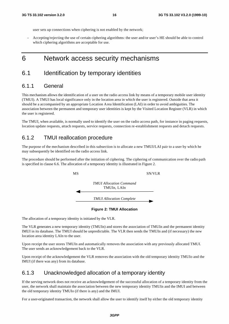
6.1.2 TMUI reallocation procedure
The purpose of the mechanism described in this subsection is to allocate a new TMUI/LAI pair to a user by which he may subsequently be identified on the radio access link.
The procedure should be performed after the initiation of ciphering. The ciphering of communication over the radio path is specified in clause 6.6. The allocation of a temporary identity is illustrated in Figure 2.
MS SN/VLR
TMUI Allocation Complete
TMUI Allocation CommandTMUIn, LAIn
Figure 2: TMUI Allocation
The allocation of a temporary identity is initiated by the VLR.
The VLR generates a new temporary identity (TMUIn) and stores the association of TMUIn and the permanent identity IMUI in its database. The TMUI should be unpredictable. The VLR then sends the TMUIn and (if necessary) the new location area identity LAIn to the user.
Upon receipt the user stores TMUIn and automatically removes the association with any previously allocated TMUI. The user sends an acknowledgement back to the VLR.
Upon receipt of the acknowledgement the VLR removes the association with the old temporary identity TMUIo and the IMUI (if there was any) from its database.
6.1.3 Unacknowledged allocation of a temporary identity
If the serving network does not receive an acknowledgement of the successful allocation of a temporary identity from the user, the network shall maintain the association between the new temporary identity TMUIn and the IMUI and between the old temporary identity TMUIo (if there is any) and the IMUI.
For a user-originated transaction, the network shall allow the user to identify itself by either the old temporary identity

3GPP
3G TS 33.102 V3.2.0 (1999-10)173G TS 33.102 version 3.2.0
TMUIo or the new temporary identity TMUIn. This allows the network to determine the temporary identity stored in the mobile station. The network shall subsequently delete the association between the other temporary identity and the IMUI, to allow the temporary identity to be allocated to another user.
For a network-originated transaction, the network shall identify the user by its permanent identity (IMUI). When radio contact has been established, the network shall instruct the user to delete any stored TMUI. When the network receives an acknowledgement from the user, the network shall delete the association between the IMUI and any TMUI to allow the released temporary identities to be allocated to other users.
Subsequently, in either of the cases above, the network may initiate the normal TMUI reallocation procedure.
Repeated failure of TMUI reallocation (passing a limit set by the operator) may be reported for O&M action.
6.1.4 Location update
In case a user identifies itself using a TMUIo/LAIo pair that was assigned by the visited VLRn the IMUI can normally be retrieved from the database. If this is not the case, the visited VLRn should request the user to identify itself by means of its permanent user identity. This mechanism is described in 6.2.
In case a user identifies itself using a TMUIo/LAIo pair that was not assigned by the visited VLRn and the visited VLRn and the previously visited VLRo exchange authentication data, the visited VLRn should request the previously visited VLRo to send the permanent user identity. This mechanism is described in 6.3.4, it is integrated in the mechanism for distribution of authentication data between VLRs. If the previously visited VLRo cannot be contacted or cannot retrieve the user identity, the visited VLRn should request the user to identify itself by means of its permanent user identity. This mechanism is described in 6.2.
6.2 Identification by a permanent identity
The mechanism described in here allows the identification of a user on the radio path by means of the permanent user identity (IMUI).
The mechanism should be invoked by the serving network whenever the user cannot be identified by means of a temporary identity. In particular, it should be used when the user registers for the first time in a serving network, or when the serving network cannot retrieve the IMUI from the TMUI by which the user identifies itself on the radio path.
The mechanism is illustrated in Figure 3.
MS SN/VLR HE
User identity responseIMUI or [HE-id || HE-message]
User identity request
User identityprocedure to the MS
User identity responseIMUI
User identity requestHE-messageUser identity
procedure to the HE
Figure 3: Identification by the permanent identity
The mechanism is initiated by the visited SN/VLR that requests the user to send its permanent identity. According to the user’s preferences, his response may contain either 1) the IMUI in cleartext, or 2) the user’s HE-identity in cleartext and an HE-message that contains an encrypted IMUI.

3GPP
3G TS 33.102 V3.2.0 (1999-10)183G TS 33.102 version 3.2.0
Note: The term HE-id denotes the 3G equivalent of the information contained in MCC || MNC.
In case the response contains the IMUI in cleartext, the procedure is ended successfully. This variant represents a breach in the provision of user identity confidentiality.
In case the response contains an encrypted IMUI, the visited SN/VLR forwards the HE message to the user’s HE in a request to send the user’s IMUI. The user’s HE then derives the IMUI from the HE-message and sends the IMUI back to the SN/VLR. Annex B describes an example mechanism that makes use of group keys to encrypt the IMUI.
6.3 Authentication and key agreement
6.3.1 General
The mechanism described here achieves mutual authentication by the user and the network showing knowledge of a secret key K which is shared between and available only to the USIM and the AuC in the user’s HE. In addition the USIM and the HE keep track of counters SQNMS and SQNHE respectively to support network authentication.
The method was chosen in such a way as to achieve maximum compatibility with the current GSM security architecture and facilitate migration from GSM to UMTS. The method is composed of a challenge/response protocol identical to the GSM subscriber authentication and key establishment protocol combined with a sequence number-based one-pass protocol for network authentication derived from the ISO standard ISO/IEC 9798-4 (section 5.1.1).
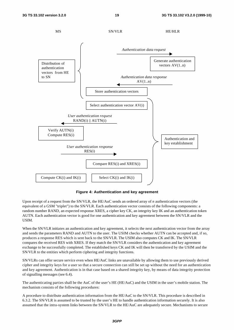
An overview of the mechanism is shown in figure 4.
3GPP
3G TS 33.102 V3.2.0 (1999-10)193G TS 33.102 version 3.2.0
MS SN/VLR HE/HLR
Generate authenticationvectors AV(1..n)
Store authentication vectors
Select authentication vector AV(i)
Authentication data request
Authentication data responseAV(1..n)
User authentication requestRAND(i) || AUTN(i)
User authentication responseRES(i)
Compare RES(i) and XRES(i)
Verify AUTN(i)Compute RES(i)
Compute CK(i) and IK(i) Select CK(i) and IK(i)
Authentication andkey establishment
Distribution ofauthenticationvectors from HEto SN
Figure 4: Authentication and key agreement
Upon receipt of a request from the SN/VLR, the HE/AuC sends an ordered array of n authentication vectors (the equivalent of a GSM "triplet") to the SN/VLR. Each authentication vector consists of the following components: a random number RAND, an expected response XRES, a cipher key CK, an integrity key IK and an authentication token AUTN. Each authentication vector is good for one authentication and key agreement between the SN/VLR and the USIM.
When the SN/VLR initiates an authentication and key agreement, it selects the next authentication vector from the array and sends the parameters RAND and AUTN to the user. The USIM checks whether AUTN can be accepted and, if so, produces a response RES which is sent back to the SN/VLR. The USIM also computes CK and IK. The SN/VLR compares the received RES with XRES. If they match the SN/VLR considers the authentication and key agreement exchange to be successfully completed. The established keys CK and IK will then be transferred by the USIM and the SN/VLR to the entities which perform ciphering and integrity functions.
SN/VLRs can offer secure service even when HE/AuC links are unavailable by allowing them to use previously derived cipher and integrity keys for a user so that a secure connection can still be set up without the need for an authentication and key agreement. Authentication is in that case based on a shared integrity key, by means of data integrity protection of signalling messages (see 6.4).
The authenticating parties shall be the AuC of the user’s HE (HE/AuC) and the USIM in the user’s mobile station. The mechanism consists of the following procedures:
A procedure to distribute authentication information from the HE/AuC to the SN/VLR. This procedure is described in 6.3.2. The SN/VLR is assumed to be trusted by the user’s HE to handle authentication information securely. It is also assumed that the intra-system links between the SN/VLR to the HE/AuC are adequately secure. Mechanisms to secure
3GPP
3G TS 33.102 V3.2.0 (1999-10)203G TS 33.102 version 3.2.0
these links are described in clause 7. It is further assumed that the user trusts the HE.
A procedure to mutually authenticate and establish new cipher and integrity keys between the SN/VLR and the MS. This procedure is described in 6.3.3.
A procedure to distribute authentication data from a previously visited VLR to the newly visited VLR. This procedure is described in 6.3.4. It is also assumed that the links between SN/VLRs are adequately secure. Mechanisms to secure these links are described in clause 7.
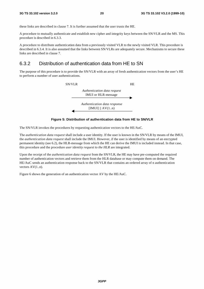
6.3.2 Distribution of authentication data from HE to SN
The purpose of this procedure is to provide the SN/VLR with an array of fresh authentication vectors from the user’s HE to perform a number of user authentications.
SN/VLR HE
Authentication data requestIMUI or HLR-message
Authentication data response[IMUI] || AV(1..n)
Figure 5: Distribution of authentication data from HE to SN/VLR
The SN/VLR invokes the procedures by requesting authentication vectors to the HE/AuC.
The authentication data request shall include a user identity. If the user is known in the SN/VLR by means of the IMUI, the authentication data request shall include the IMUI. However, if the user is identified by means of an encrypted permanent identity (see 6.2), the HLR-message from which the HE can derive the IMUI is included instead. In that case, this procedure and the procedure user identity request to the HLR are integrated.
Upon the receipt of the authentication data request from the SN/VLR, the HE may have pre-computed the required number of authentication vectors and retrieve them from the HLR database or may compute them on demand. The HE/AuC sends an authentication response back to the SN/VLR that contains an ordered array of n authentication vectors AV(1..n).
Figure 6 shows the generation of an authentication vector AV by the HE/AuC.

3GPP
3G TS 33.102 V3.2.0 (1999-10)213G TS 33.102 version 3.2.0
K
SQNRAND
f1 f2 f3 f4 f5
MAC XRES CK IK AK
AUTN := SQN ⊕ AK || AMF || MAC
AV := RAND || XRES || CK || IK || AUTN
Generate SQN
Generate RAND
AMF
Figure 6: Generation of an authentication vector
The HE/AuC starts with generating a fresh sequence number SQN and an unpredictable challenge RAND.
For each user the HE/AuC keeps track of a counter: SQNHE
To generate a fresh sequence number, the counter is incremented and subsequently the SQN is set to the new counter value.
Note 1: The HE has some flexibility in the management of sequence numbers. Annex C and Annex F.3 contain alternative methods for the generation and verification of sequence numbers.
An authentication and key management field AMF is included in the authentication token of each authentication vector. Example uses of this field are included in Annex F.
Subsequently the following values are computed:
- a message authentication code MAC = f1K(SQN || RAND || AMF) where f1 is a message authentication function;
- an expected response XRES = f2K (RAND) where f2 is a (possibly truncated) message authentication function;
- a cipher key CK = f3K (RAND) where f3 is a key generating function;
- an integrity key IK = f4K (RAND) where f4 is a key generating function;
- an anonymity key AK = f5K (RAND) where f5 is a key generating function.
Finally the authentication token AUTN = SQN ⊕ AK || AMF || MAC is constructed.
Here, AK is an anonymity key used to conceal the sequence number as the latter may expose the identity and location of the user. The concealment of the sequence number is to protect against passive attacks only.
Note 1: The need for f5 to use a long-term key different from K is ffs.
3GPP
3G TS 33.102 V3.2.0 (1999-10)223G TS 33.102 version 3.2.0
Note 2: The requirements on f3, f4 and f5 are ffs.
Note 3: It is also ffs in how far the functions f1, ..., f5 need to differ and how they may be suitably combined.
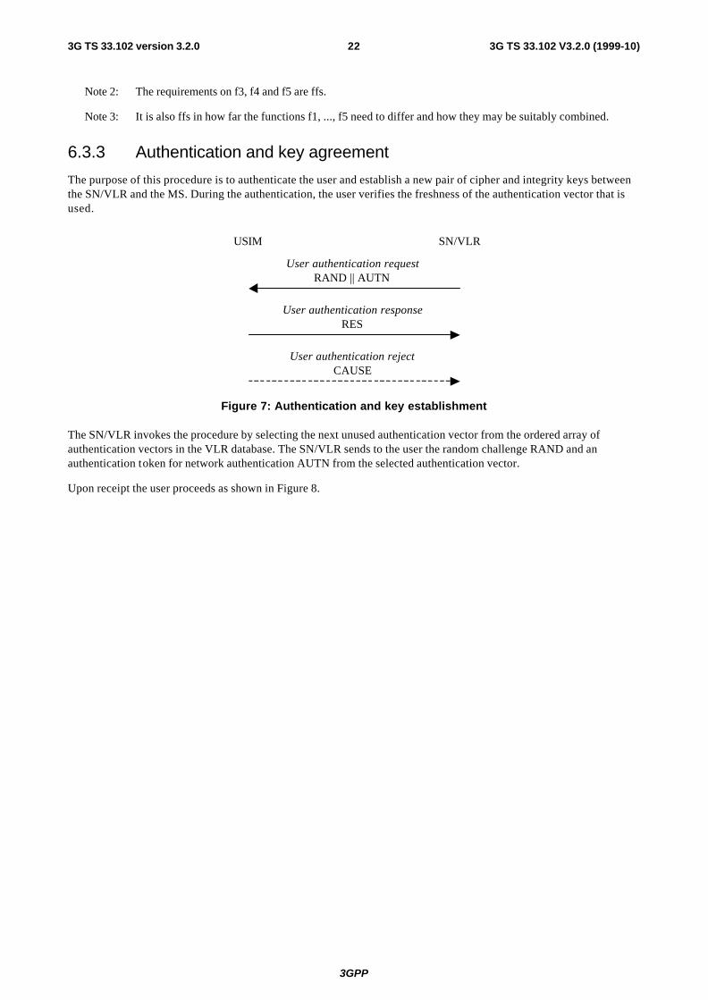
6.3.3 Authentication and key agreement
The purpose of this procedure is to authenticate the user and establish a new pair of cipher and integrity keys between the SN/VLR and the MS. During the authentication, the user verifies the freshness of the authentication vector that is used.
USIM SN/VLR
User authentication requestRAND || AUTN
User authentication responseRES
User authentication rejectCAUSE
Figure 7: Authentication and key establishment
The SN/VLR invokes the procedure by selecting the next unused authentication vector from the ordered array of authentication vectors in the VLR database. The SN/VLR sends to the user the random challenge RAND and an authentication token for network authentication AUTN from the selected authentication vector.
Upon receipt the user proceeds as shown in Figure 8.

3GPP
3G TS 33.102 V3.2.0 (1999-10)233G TS 33.102 version 3.2.0
K
SQN
RAND
f1 f2 f3 f4
f5
XMAC RES CK IK
AK
SQN ⊕ AK AMF MAC
AUTN
Verify MAC = XMAC
Verify SQN > SQNHE
⊕
Figure 8: User authentication function in the USIM
Upon receipt of RAND and AUTN the user first computes the anonymity key AK = f5K (RAND) and retrieves the sequence number SQN = (SQN ⊕ AK) ⊕ AK.
Next the user computes XMAC = f1K (SQN || RAND || AMF) and compares this with MAC which is included in AUTN. If they are different, the user sends user authentication reject back to the SN/VLR with an indication of the cause and the user abandons the procedure.
Next the user verifies that the received sequence number SQN is in the correct range.
The USIM keeps track of a counter: SQNMS.
To verify that the sequence number SQN is in the correct range, the USIM compares SQN with SQNMS. If SQN > SQNMS
the MS considers the sequence number to be in the correct range and subsequently sets SQNMS to SQN.
Note: The MS and the HE have some flexibility in the management of sequence numbers. Annex C and Annex F.3 contain alternative methods for the generation and verification of sequence numbers.
If the user considers the sequence number to be not in the correct range, he sends synchronisation failure back to the SN/VLR including an appropriate parameter, and abandons the procedure.
The synchronisation failure message contains the parameter RANDMS || AUTS. Here RANDMS is the random value stored on the MS which was received in user authentication request causing the last update of SQNMS . It is AUTS = Conc(SQNMS ) || MACS. Conc(SQNMS) = SQNMS ⊕ f5K(RANDMS) is the concealed value of the counter SQNMS in the MS, and. MACS = f1*K(SQNMS || RAND || AMF) where RAND is the random value received in the current user authentication request. f1* is a message authentication code (MAC) function with the property that no valuable information can be inferred from the function values of f1* about those of f1, ... , f5 and vice versa.
3GPP
3G TS 33.102 V3.2.0 (1999-10)243G TS 33.102 version 3.2.0
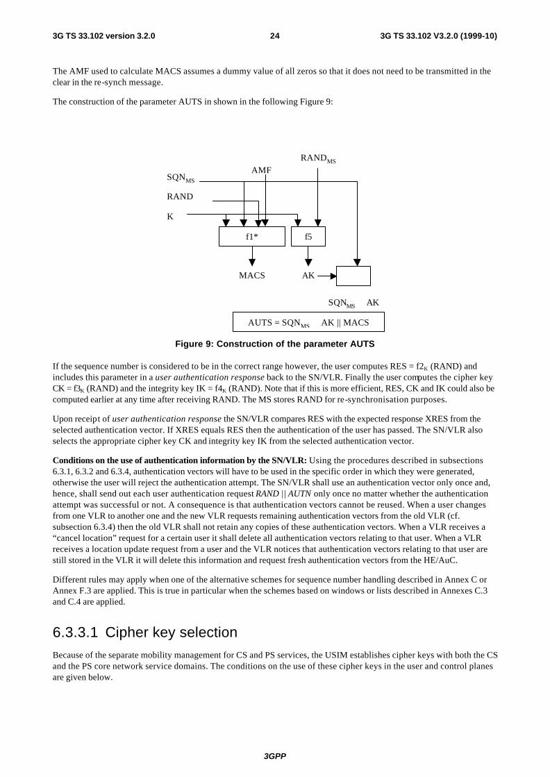
The AMF used to calculate MACS assumes a dummy value of all zeros so that it does not need to be transmitted in the clear in the re-synch message.
The construction of the parameter AUTS in shown in the following Figure 9:
K
SQNMS
RANDMS
f1* f5
MACS AK
RAND
⊕
SQNMS ⊕ AK
AUTS = SQNMS ⊕ AK || MACS
AMF
Figure 9: Construction of the parameter AUTS
If the sequence number is considered to be in the correct range however, the user computes RES = f2K (RAND) and includes this parameter in a user authentication response back to the SN/VLR. Finally the user computes the cipher key CK = f3K (RAND) and the integrity key IK = f4K (RAND). Note that if this is more efficient, RES, CK and IK could also be computed earlier at any time after receiving RAND. The MS stores RAND for re-synchronisation purposes.
Upon receipt of user authentication response the SN/VLR compares RES with the expected response XRES from the selected authentication vector. If XRES equals RES then the authentication of the user has passed. The SN/VLR also selects the appropriate cipher key CK and integrity key IK from the selected authentication vector.
Conditions on the use of authentication information by the SN/VLR: Using the procedures described in subsections 6.3.1, 6.3.2 and 6.3.4, authentication vectors will have to be used in the specific order in which they were generated, otherwise the user will reject the authentication attempt. The SN/VLR shall use an authentication vector only once and, hence, shall send out each user authentication request RAND || AUTN only once no matter whether the authentication attempt was successful or not. A consequence is that authentication vectors cannot be reused. When a user changes from one VLR to another one and the new VLR requests remaining authentication vectors from the old VLR (cf. subsection 6.3.4) then the old VLR shall not retain any copies of these authentication vectors. When a VLR receives a “cancel location” request for a certain user it shall delete all authentication vectors relating to that user. When a VLR receives a location update request from a user and the VLR notices that authentication vectors relating to that user are still stored in the VLR it will delete this information and request fresh authentication vectors from the HE/AuC.
Different rules may apply when one of the alternative schemes for sequence number handling described in Annex C or Annex F.3 are applied. This is true in particular when the schemes based on windows or lists described in Annexes C.3 and C.4 are applied.
6.3.3.1 Cipher key selection
Because of the separate mobility management for CS and PS services, the USIM establishes cipher keys with both the CS and the PS core network service domains. The conditions on the use of these cipher keys in the user and control planes are given below.
3GPP
3G TS 33.102 V3.2.0 (1999-10)253G TS 33.102 version 3.2.0
6.3.3.1.1 User plane
The CS user data connections are ciphered with the cipher key CKCS established between the user and the 3G CS core network service domain and identified in the security mode setting procedure. The PS user data connections are ciphered with the cipher key CKPS established between the user and the 3G PS core network service domain and identified in the security mode setting procedure.
6.3.3.1.2 Control plane
When a security mode setting procedure is performed, the cipher/integrity key set by this procedure is applied to the signalling plane, what ever core network service domain is specified in the procedure. This may require that the cipher/integrity key of an (already ciphered/integrity protected) ongoing signalling connection is changed. This change should be completed within five seconds.
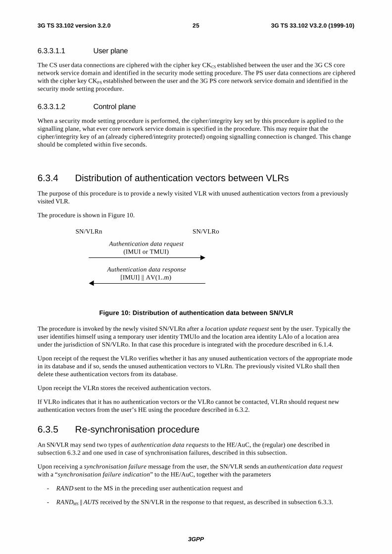
6.3.4 Distribution of authentication vectors between VLRs
The purpose of this procedure is to provide a newly visited VLR with unused authentication vectors from a previously visited VLR.
The procedure is shown in Figure 10.
SN/VLRn SN/VLRo
Authentication data request(IMUI or TMUI)
Authentication data response[IMUI] || AV(1..m)
Figure 10: Distribution of authentication data between SN/VLR
The procedure is invoked by the newly visited SN/VLRn after a location update request sent by the user. Typically the user identifies himself using a temporary user identity TMUIo and the location area identity LAIo of a location area under the jurisdiction of SN/VLRo. In that case this procedure is integrated with the procedure described in 6.1.4.
Upon receipt of the request the VLRo verifies whether it has any unused authentication vectors of the appropriate mode in its database and if so, sends the unused authentication vectors to VLRn. The previously visited VLRo shall then delete these authentication vectors from its database.
Upon receipt the VLRn stores the received authentication vectors.
If VLRo indicates that it has no authentication vectors or the VLRo cannot be contacted, VLRn should request new authentication vectors from the user’s HE using the procedure described in 6.3.2.
6.3.5 Re-synchronisation procedure
An SN/VLR may send two types of authentication data requests to the HE/AuC, the (regular) one described in subsection 6.3.2 and one used in case of synchronisation failures, described in this subsection.
Upon receiving a synchronisation failure message from the user, the SN/VLR sends an authentication data request with a “synchronisation failure indication” to the HE/AuC, together with the parameters
- RAND sent to the MS in the preceding user authentication request and
- RANDMS || AUTS received by the SN/VLR in the response to that request, as described in subsection 6.3.3.

3GPP
3G TS 33.102 V3.2.0 (1999-10)263G TS 33.102 version 3.2.0
An SN/VLR will not react to unsolicited “ synchronisation failure indication” messages from the MS.
The SN/VLR does not send new user authentication requests to the user before having received the response to its authentication data request from the HE/AuC (or before it is timed out).
When the HE/AuC receives an authentication data request with a “synchronisation failure indication” it acts as follows: The HE/AuC verifies AUTS by computing f5K(RANDMS), retrieving SQNMS from Conc(SQNMS) and verifying MACS (cf. subsection 6.3.3.). If the verification is successful, but SQNMS is such that SQNHE is not in the correct range then the HE/AuC resets the value of the counter SQNHE to SQNMS. Otherwise, the HE/AuC leaves SQNHE unchanged.
In all cases the HE/AuC sends an authentication data response with a new batch of authentication vectors to the SN/VLR. If the counter SQNHE was not reset then these authentication vectors can be taken from storage, otherwise they are newly generated after resetting SQNHE. In order to reduce the real-time computation burden on the HE/AuC, the HE/AuC may also send only a single authentication vector in the latter case.
Whenever the SN/VLR receives a new batch of authentication vectors from the HE/AuC in an authentication data response it deletes the old ones for that user in the VLR.
The user may now be authenticated based on a new authentication vector from the HE/AuC. Optionally, in order to minimise extra effort by the HE/AuC, in an authentication data request with synchronisation failure indication the SN/VLR may also send the concealed sequence number Conc(SQNSN) corresponding to the last authentication vector received which the SN/VLR has in storage, i.e. it may send Conc(SQNSN) = RANDSN || SQNSN⊕f5K(RANDMS).
On receipt the HE/AuC retrieves SQNSN from Conc(SQNSN). If the counter in the HE/AuC did not have to be reset and if SQNSN = SQNHE the HE/AuC informs the SN/VLR accordingly and does not send fresh authentication vectors. (In this way, a synchronisation failure does not cause the HE/AuC to produce extra authentication vectors when they are not needed.)
Figure 11 shows how re-synchronisation is achieved by combining a user authentication request answered by a synchronisation failure message (as described in subclause 6.3.3) with an authentication data request with synchronisation failure indication answered by an authentication data response (as described in this subclause).
Figure 11: Re-synchronisation procedure
6.3.6 Length of sequence numbers
Sequence numbers shall be sufficiently long so that they cannot wrap around during the lifetime of the system. Consequently, in normal operations neither SQNMS nor SQNHE can wrap around during the lifetime of a USIM.
MS SN HE
User auth request (RAND || AUTN)
synch failure (RANDMS || AUTS)
Auth data response (auth
Auth data request (id), synch failure ind (RAND || RANDMS || AUTS)

3GPP
3G TS 33.102 V3.2.0 (1999-10)273G TS 33.102 version 3.2.0
Note 1: If the counters would derive sequence numbers from time (see Annex C), then a 32-bit counter that is derived from the number of seconds that have elapsed since January 1, 2000 would only wrap around in the year 2136. So a length of 32-bits for the sequence numbers and counters should be sufficient. For individual incremental counters, a smaller range of sequence numbers should be sufficient, as authentication and key agreement is expected to occur far less frequently than once every second. Shorter lengths would however exclude the use of time-derived sequence numbers.
Note 2: Sequence numbers for CS and PS operation are expected to have the same length.
6.3.7 Support for window and list mechanisms
In Annex C.3 and Annex C.4 respectively, the window and list mechanisms for sequence number management in the USIM are described. If one of these mechanisms is employed in the USIM and if there is no need to conceal sequence numbers then the MS shall send information on the current value of the lowest entry SQNLO in the window or list to the SN/VLR at every location update. Sequence numbers which do not need to be concealed may be generated according to Annex C.2 or Annex C.6.
When the SN/VLR authenticates a user for the first time after receiving a new value SQNLO from the MS then the SN/VLR checks whether the sequence number of the authentication vector it wants to use is greater than SQNLO. The SN/VLR uses the AV only if this is the case. Otherwise, the AV is discarded. If all AVs have to be discarded the SN/VLR requests new ones from the HE/AuC.
6.4 Local authentication and connection establishment
6.4.1 Cipher key and integrity key setting
Mutual key setting is the procedure that allows the MS and the RNC to agree on the key IK used to compute message authentication codes using algorithm UIA. Key setting is triggered by the authentication procedure and described in xxx6.3. Key setting may be initiated by the network as often as the network operator wishes. Key setting can occur as soon as the identity of the mobile subscriber (i.e. TMUI or IMUI) is known by the SN/VLR. The key IK is stored in the SN/VLR and transferred to the RNC when it is needed. The key IK is stored in the USIM until it is updated at the next authentication.
6.4.2 Cipher key and integrity mode negotiation
When an MS wishes to establish a connection with the network, the MS shall indicate to the network in the MS/USIM Classmark which cipher and integrity algorithms the MS supports. This message itself must be integrity protected. As it is the case that the RNC does not have the integrity key IK when receiving the MS/USIM Classmark the cipher and imust be stored in the RNC and the integrity of the classmark with the newly generated IK and this value is transmitted to the RNC after the authentication procedure is complete.
The network shall compare its integrity protection capabilities and preferences, and any special requirements of the subscription of the MS, with those indicated by the MS and act according to the following rules:
1) If the MS and the SN have no versions of the UIA algorithm in common, then the connection shall be released.
2) If the MS and the SN have at least one version of the UIA algorithm in common, then the network shall select one of the mutually acceptable versions of the UIA algorithm for use on that connection.
The network shall compare its ciphering capabilities and preferences, and any special requirements of the subscription of the MS, with those indicated by the MS and act according to the following rules:
1) If the MS and the network have no versions of the UEA algorithm in common and the network is not prepared to use an unciphered connection, then the connection shall be released.
2) If the MS and the network have at least one version of the UEA algorithm in common, then the network shall select one of the mutually acceptable versions of the UEA algorithm for use on that connection.
3) If the MS and the network have no versions of the UEA algorithm in common and the user (respectively the
3GPP
3G TS 33.102 V3.2.0 (1999-10)283G TS 33.102 version 3.2.0
user’s HE) and the SN are willing to use an unciphered connection, then an unciphered connection shall be used.
6.4.3 Cipher key and integrity key lifetime
Authentication and key agreement which generates cipher/integrity keys is not mandatory at call set-up, and there is therefore the possibility of unlimited and malicious re-use of compromised keys. A mechanism is needed to ensure that a particular cipher/integrity key set is not used for an unlimited period of time, to avoid attacks using compromised keys. The USIM shall therefore contain a mechanism to limit the amount of data that is protected by an access link key set.
Each time an RRC connection is released the highest value of the hyperframe number (the current value of COUNT) of the bearers that were protected in that RRC connection is stored in the USIM. When the next RRC connection is established that value is read from the USIM and incremented by one.
The USIM shall trigger the generation of a new access link key set (a cipher key and an integrity key) if the counter reaches a maximum value set by the operator and stored in the USIM at the next RRC connection request message sent out.
This mechanism will ensure that a cipher/integrity key set cannot be reused more times than the limit set by the operator.
6.4.4 Cipher key and integrity key identification
The key set identifier (KSI) is a number which is associated with the cipher and integrity keys derived during authentication. It is stored together with the cipher and integrity keys in the MS and in the network.
The key set identifier is used to allow key re-use during subsequent connection set-ups. The KSI is used to verify whether the MS and the SN are to use the same cipher key and integrity key.
6.4.5 Security mode set-up procedure
This section describes one common procedure for both ciphering and integrity protection set-up. This procedure is mandatory. The message sequence flow below describes the information transfer at initial connection establishment, possible authentication and start of integrity protection and possible ciphering.

3GPP
3G TS 33.102 V3.2.0 (1999-10)293G TS 33.102 version 3.2.0
UEUSIM
2. “Initial L3 message” with UE identity, UE classmark, KSI etc.
MSC/VLRSGSN
3. Authentication and key generation
1. Storage of HFN
4 Select allowed UIAs and UEAs
SRNC
1. RRC connection establishment including transfer ofHFN from UE to SRNC
5. Security mode command (UIA, IK, UE classmark, UEA, CK, etc.)
6. Generate FRESH Start integrity; start deciphering
7. Security control command (CN domain,
UIA, FRESH, UE classmark, UEA, etc.)
10. Verify received message; start ciphering
9. Security control response
11. Security mode complete
8. Control of UE classmark, Start ofintegrity, Verify message, Startciphering, etc.
“UE classmark” contains supported UIA and UEA
Note 1: The network must have the “UE security capability” information, which is part of the “UE Classmark”, before the integrity protection can start, i.e. the “UE Classmark” must be sent to the network in an unprotected message. Returning the “UE Classmark” later on to the UE in a protected message will give UE the possibility to verify that it was the correct “UE Classmark” that reached the network. This latter point, as well as the RRC interwork described below, is yet to be agreed in RAN WG2.
Detailed description of the flow above:
1. RRC connection establishment includes the transfer from UE to RNC of the hyperframe number to be used as part of one of the input parameters for the integrity algorithm and for the ciphering algorithm. The COUNT-I parameter (together with COUNT which is used for ciphering) is stored in the SRNC.
2. The UE sends the Initial L3 message (Location update request, CM service request, Routing area update request, attach request, paging response etc.) to the relevant CN domain. This message contains relevant MM information and the UE classmark IE, which includes information on the UIA(s) and UEA(s) supported by the UE. The KSI (Key Set Identifier) is the number allocated by the CN at the last authentication for this CN domain.
3. Authentication of the user and generation of new security keys (IK and CK) may be performed. A new KSI will then also be allocated.
4. The CN node determines which UIAs and UEAs that are allowed to be used.
5. The CN initiates integrity (and possible also ciphering) by sending the RANAP message Security Mode Command to SRNC. This message contains a list of allowed UIAs and the IK to be used. It may also contain the allowed UEAs and the CK to be used. This message contains also the UE classmark IE to be sent transparently to the UE.

3GPP
3G TS 33.102 V3.2.0 (1999-10)303G TS 33.102 version 3.2.0
6. The SRNC decides which algorithms to use by selecting the first UEA and the first UIA it supports from the list.The SRNC generates a random value FRESH and initiates the downlink integrity protection. If SRNC supports no UIA algorithms in the list, it sends a SECURITY MODE REJECT message to CN.
7. The SRNC generates the RRC message Security control command. The message includes the UE classmark IE, the UIA and FRESH to be used and possibly also the UEA to be used. Additional information (start of ciphering) may also be included. Since we have two CNs with an IK each, the network must indicate which IK to use. This is obtained by including a CN type indicator information in “Security control command”. Before sending this message to the UE, the SRNC generates the MAC-I (Message Authentication Code for Integrity) and attaches this information to the message.
8. At reception of the Security control command message, the UE controls that the UE classmark IE received is equal to the UE classmark IE sent in the initial message. The UE computes XMAC-I on the message received by using the indicated UIA, the stored COUNT-I and the received FRESH parameter. The UE verifies the integrity of the message by comparing the received MAC-I with the generated XMAC-I.
9. If all controls are successful, the UE compiles the RRC message Security control command response and generates the MAC-I for this message. If any control is not successful, a SECURITY CONTROL REJECT message is sent from the UE .
10. At reception of the response message, the SRNC computes the XMAC-I on the message. The SRNC verifies the data integrity of the message by comparing the received MAC-I with the generated XMAC-I.
11. The transfer of the RANAP message Security Mode Complete response from SRNC to the CN node ends the procedure.
The Security mode command to UE starts the downlink integrity protection, i.e. also all following downlink messages sent to the UE are integrity protected and possibly ciphered. The Security mode command response from UE starts the uplink integrity protection and possible ciphering, i.e. also all following messages sent from the UE are integrity protected and possibly ciphered.
Signalling procedures in the case of an unsuccessful integrity check
The following procedure is used by the RNC to request the CN to perform an authentication and to provide a new CK and IK in case of unsuccessful integrity check. This can happen on the RNC side or in the UE side. In the latter case the UE sends a SECURITY CONTROL REJECT message to the RNC.
CNUE
1. Security check request
3. Security mode command orSecurity check response
RNC
2. Authentication and key agreement
RNC detects that new security parameters are needed. This may be triggered by (repeated) failure of integrity checks (e.g. COUNT-I went out of synchronisation), or at handover the new RNC does not support an algorithm selected by the old RNC, etc.
1. RNC sends a SECURITY CHECK REQUEST message to CN (indicating cause of the request).
2. The CN performs the authentication and key agreement procedure.

3GPP
3G TS 33.102 V3.2.0 (1999-10)313G TS 33.102 version 3.2.0
3. If the authentication is successful, the CN sends a Security mode command to RNC. This will restart the ciphering and integrity check with new parameters. If the authentication is not successful, the CN sends a SECURITY CHECK RESPONSE (Cause) to RNC.
4. If the failure situation persists, the connection should be dropped.
6.5 Access link data integrity
6.5.1 General
Most RRC, MM and CC signalling information elements are considered sensitive and must be integrity protected. A message authentication function shall be applied on these signalling information elements transmitted between the MS and the SN.
The UMTS Integrity Algorithm (UIA) shall be used with an Integrity Key (IK) to compute a message authentication code for a given message.
All signalling messages except the following ones shall be integrity protected:
- Notification
- Paging Type 1
- RRC Connection Request
- RRC Connection Setup
- RRC Connection Setup Complete
- RRC Connection Reject
- All System Information messages.
6.5.2 Integrity algorithm
The UIA shall be implemented in the UE and in the RNC.
Figure 12 illustrates the use of the UIA to authenticate the data integrity of a signalling message.
UIAIK
MAC-I
MESSAGE
COUNT
FRESH
SenderUE or RNC
UIAIK
XMAC-I
MESSAGE
COUNT
FRESH
ReceiverUE or RNC
Figure 12: Derivation of MAC-I (or XMAC-I) on a signalling message
The input parameters to the algorithm are the Integrity Key (IK), a time dependent input (COUNT-I), a random value generated by the network side (FRESH), the direction bit (DIRECTION) and the signalling data (MESSAGE). Based on these input parameters the user computes message authentication code for data integrity (MAC-I) using the UMTS Integrity Algorithm (UIA). The MAC-I is then appended to the message when sent over the radio access link. The receiver computes XMAC-I on the message received in the same way as the sender computed MAC-I on the message
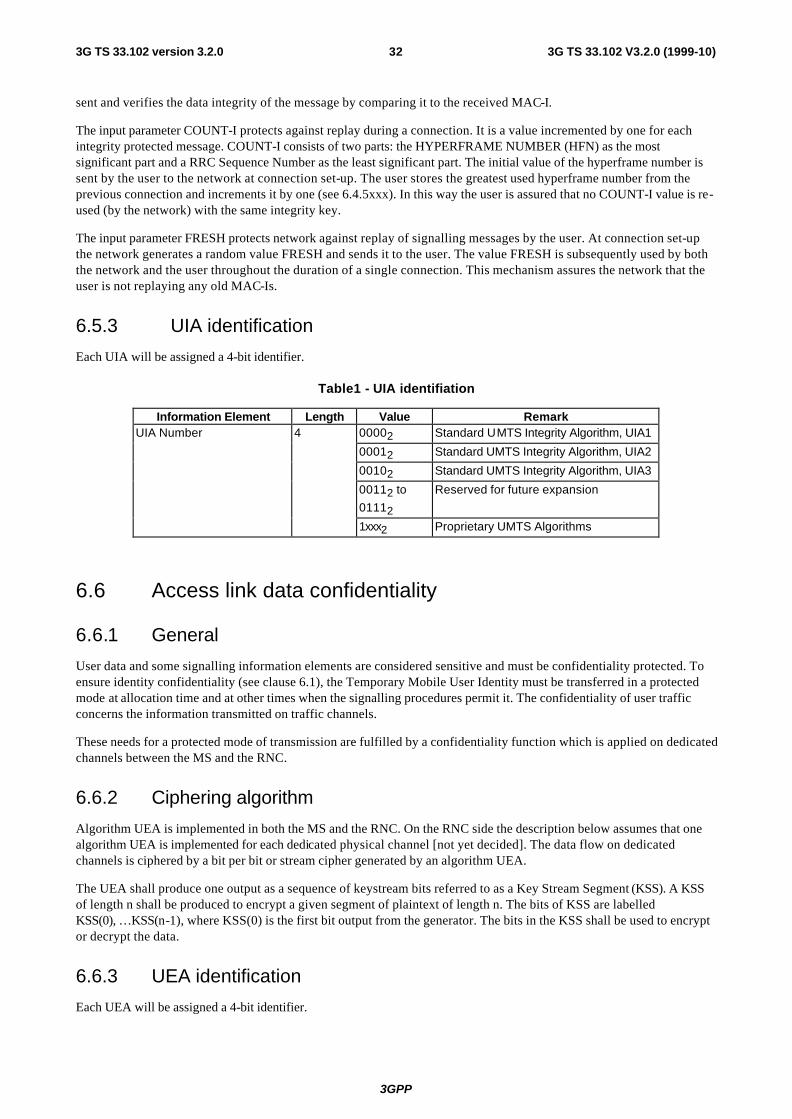
3GPP
3G TS 33.102 V3.2.0 (1999-10)323G TS 33.102 version 3.2.0
sent and verifies the data integrity of the message by comparing it to the received MAC-I.
The input parameter COUNT-I protects against replay during a connection. It is a value incremented by one for each integrity protected message. COUNT-I consists of two parts: the HYPERFRAME NUMBER (HFN) as the most significant part and a RRC Sequence Number as the least significant part. The initial value of the hyperframe number is sent by the user to the network at connection set-up. The user stores the greatest used hyperframe number from the previous connection and increments it by one (see 6.4.5xxx). In this way the user is assured that no COUNT-I value is re-used (by the network) with the same integrity key.
The input parameter FRESH protects network against replay of signalling messages by the user. At connection set-up the network generates a random value FRESH and sends it to the user. The value FRESH is subsequently used by both the network and the user throughout the duration of a single connection. This mechanism assures the network that the user is not replaying any old MAC-Is.
6.5.3 UIA identification
Each UIA will be assigned a 4-bit identifier.
Table1 - UIA identifiation
Information Element Length Value Remark UIA Number 4 00002 Standard UMTS Integrity Algorithm, UIA1
00012 Standard UMTS Integrity Algorithm, UIA2
00102 Standard UMTS Integrity Algorithm, UIA3
00112 to
01112
Reserved for future expansion
1xxx2 Proprietary UMTS Algorithms
6.6 Access link data confidentiality
6.6.1 General
User data and some signalling information elements are considered sensitive and must be confidentiality protected. To ensure identity confidentiality (see clause 6.1), the Temporary Mobile User Identity must be transferred in a protected mode at allocation time and at other times when the signalling procedures permit it. The confidentiality of user traffic concerns the information transmitted on traffic channels.
These needs for a protected mode of transmission are fulfilled by a confidentiality function which is applied on dedicated channels between the MS and the RNC.
6.6.2 Ciphering algorithm
Algorithm UEA is implemented in both the MS and the RNC. On the RNC side the description below assumes that one algorithm UEA is implemented for each dedicated physical channel [not yet decided]. The data flow on dedicated channels is ciphered by a bit per bit or stream cipher generated by an algorithm UEA.
The UEA shall produce one output as a sequence of keystream bits referred to as a Key Stream Segment (KSS). A KSS of length n shall be produced to encrypt a given segment of plaintext of length n. The bits of KSS are labelled KSS(0), …KSS(n-1), where KSS(0) is the first bit output from the generator. The bits in the KSS shall be used to encrypt or decrypt the data.
6.6.3 UEA identification
Each UEA will be assigned a 4-bit identifier.
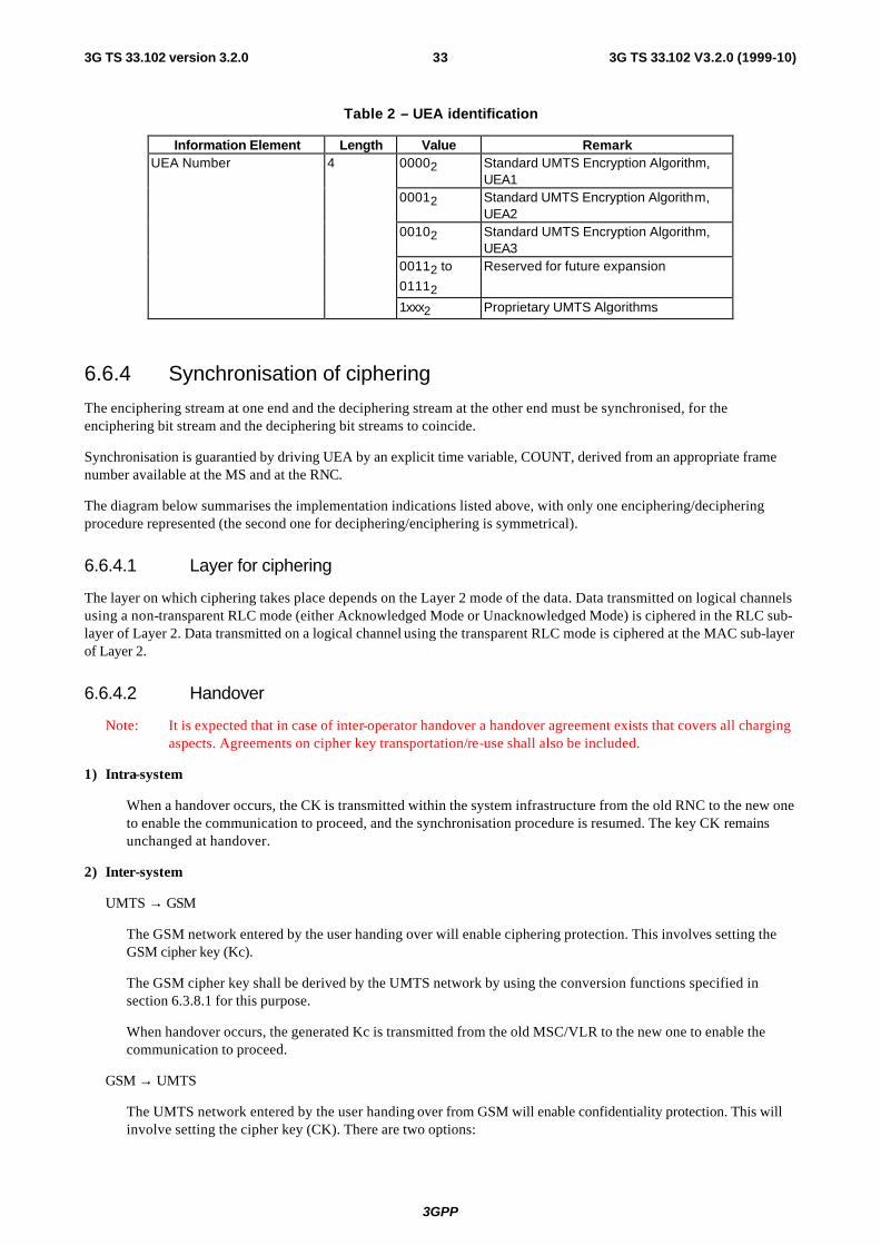
3GPP
3G TS 33.102 V3.2.0 (1999-10)333G TS 33.102 version 3.2.0
Table 2 – UEA identification
Information Element Length Value Remark UEA Number 4 00002 Standard UMTS Encryption Algorithm,
UEA1 00012 Standard UMTS Encryption Algorithm,
UEA2 00102 Standard UMTS Encryption Algorithm,
UEA3 00112 to
01112
Reserved for future expansion
1xxx2 Proprietary UMTS Algorithms
6.6.4 Synchronisation of ciphering
The enciphering stream at one end and the deciphering stream at the other end must be synchronised, for the enciphering bit stream and the deciphering bit streams to coincide.
Synchronisation is guarantied by driving UEA by an explicit time variable, COUNT, derived from an appropriate frame number available at the MS and at the RNC.
The diagram below summarises the implementation indications listed above, with only one enciphering/deciphering procedure represented (the second one for deciphering/enciphering is symmetrical).
6.6.4.1 Layer for ciphering
The layer on which ciphering takes place depends on the Layer 2 mode of the data. Data transmitted on logical channels using a non-transparent RLC mode (either Acknowledged Mode or Unacknowledged Mode) is ciphered in the RLC sub-layer of Layer 2. Data transmitted on a logical channel using the transparent RLC mode is ciphered at the MAC sub-layer of Layer 2.
6.6.4.2 Handover
Note: It is expected that in case of inter-operator handover a handover agreement exists that covers all charging aspects. Agreements on cipher key transportation/re-use shall also be included.
1) Intra-system
When a handover occurs, the CK is transmitted within the system infrastructure from the old RNC to the new one to enable the communication to proceed, and the synchronisation procedure is resumed. The key CK remains unchanged at handover.
2) Inter-system
UMTS → GSM
The GSM network entered by the user handing over will enable ciphering protection. This involves setting the GSM cipher key (Kc).
The GSM cipher key shall be derived by the UMTS network by using the conversion functions specified in section 6.3.8.1 for this purpose.
When handover occurs, the generated Kc is transmitted from the old MSC/VLR to the new one to enable the communication to proceed.
GSM → UMTS
The UMTS network entered by the user handing over from GSM will enable confidentiality protection. This will involve setting the cipher key (CK). There are two options:

3GPP
3G TS 33.102 V3.2.0 (1999-10)343G TS 33.102 version 3.2.0
a) Handover from a UMTS capable GSM network
When handover occurs, the CK is transmitted from the old MSC/VLR to the new one to enable the communication to proceed.
b) Handover from a non-UMTS capable network. The method below is not recommended but presented if it will be a service requirement. There are doubts whether there is a requirement for this kind of handover and whether it is possible on, for instance, the MAP/E interface
The UMTS cipher key shall be derived by the UMTS network an UE by using the conversion functions specified in section 6.3.8.2 for this purpose.
When handover occurs, the derived Kc is transmitted form the old MSC/VLR to the new one to enable the communication to proceed.
6.7 Network-wide encryption
6.7.1 Introduction
Subclause 6.6 specifies how signalling information, user identity and user traffic information may be confidentiality protected by providing a protected mode of transmission on dedicated channels between the UE and the RNC. Network-wide confidentiality is an extension of this security feature which provides a protected mode of transmission on user traffic channels across the entire network. This gives users assurance that their traffic is protected against eavesdropping on every link within the network, i.e. not just the particularly vulnerable radio links in the access network, but also on the fixed links within the core network.
If network-wide confidentiality of user traffic is provided we assume that access link confidentiality of user traffic between UE and RNC will be replaced with the network-wide service. However, we note that access link confidentiality of signalling information and user identity between UE and RNC will be applied regardless of whether the network-wide user traffic confidentiality service is applied or not.
The provision of an network-wide confidentiality service in 3GMS has an obvious impact on lawful interception. We assume that the same lawful interception interface is required in 3GMS as in second generation systems regardless of whether network-wide confidentiality is applied by the network or not. Thus, we assume that it must be possible to remove any network-wide confidentiality protection within the core network to provide access to plaintext user traffic at the lawful interception interface.
We assume that network-wide confidentiality will be provided by protecting transmissions on user traffic channels using a synchronous stream cipher. This will involve the specification of a standard method for ciphering user traffic on an end-to-end basis and a standard method for managing the ciphering key required at the end points of the protected channel.
6.7.2 Ciphering method
It is assumed that the network-wide encryption algorithm shall be a synchronous stream cipher similar to the access link encryption algorithm. Indeed, it would be desirable to use the same algorithm for access link encryption and for network-wide encryption.
The network-wide synchronous stream cipher shall contain a key stream generator which shall have (at least) two inputs: the end-to-end cipher key (Ks) and an initialisation value (IV). The plaintext shall be encrypted using the key stream by applying an exclusive-or operation to the plaintext on a bit per bit basis to generate the ciphertext. The decryption operation shall involve applying the same key stream to the ciphertext to recover the plaintext.
Synchronisation of the key stream shall be achieved using the initialisation value. Synchronisation information shall be available at both end points of the communication and shall be used to maintain alignment of the key stream. For example, it might be necessary to transmit explicit end-to-end synchronisation frames with the user traffic at certain intervals. Alternatively, it might be possible to use some existing frame structure for network-wide encryption synchronisation purposes. The frequency at which synchronisation information must be made available at each end to ensure reliable
3GPP
3G TS 33.102 V3.2.0 (1999-10)353G TS 33.102 version 3.2.0
transmission will depend on the exact nature of the end-to-end user traffic channel.
Protection against replay of user traffic shall be achieved through the use of a time variable initialisation vector combined with a time variable cipher key. If the same cipher key is used in more than one call then it may be necessary to include a third input to the key stream generator such as a call-id or a time-stamp to protect against replay of the whole call. Note that the stream cipher does not protect against bit toggling so other mechanisms must be used if this type of integrity protection is required on user traffic.
For encryption of voice traffic we assume that Transcoder Free Operation (TFO) is used between the two end points such that the structure and ordering of the transmitted data is maintained with the same boundary conditions at each end of the link. Note that in the initial phases of 3GMS, transcoder free operation may only be possible for user traffic channels which terminate within the same serving network. Furthermore, TFO may only be possible if the entire communication path is within the same serving network. Thus, in non optimal routing cases where the tromboning effect occurs, TFO may not be available, even if the traffic channel terminates within the same serving network.
For encryption of data traffic we assume that a transparent data service is used between the two end points such that the structure and ordering of transmitted data is maintained with the same boundary conditions at each end of the link.
To satisfy lawful interception requirements it must be possible to decrypt end-to-end encrypted traffic within the core network to provide access to plaintext user traffic. Thus decryption facilities (and the end-to-end encryption key) must be available in the core network for lawful interception reasons. Note also that if transcoder free operation is used on voice traffic channels, transcoders must be available in the core network for lawful interception reasons whether network-wide encryption is provided or not.
Issues for further study:
- Specification of encryption synchronisation mechanism;
- Adaptation of TFO voice traffic channels for network-wide confidentiality;
- Adaptation of data traffic channels for network-wide confidentiality;
- The ability to terminate network-wide encryption at network gateways for inter-network user traffic channels;
- The ability to handle multiparty calls, explicit call transfer and other supplementary services;
- Network-wide encryption control – algorithm selection, mode selection, user control
6.7.3 Key management
6.7.3.1 General case
We assume that signalling links within the network are confidentially protected on a link-by-link basis. In particular, we assume that the UE to RNC signalling links are protected using access link security domain keys (see clause 6). We also assume that VLR to RNC signalling links and core network signalling links are protected using network security domain keys (see clause 7). Note that if network-wide encryption can be provided across serving network boundaries (e.g. because inter-network TFO is available) then the signalling links requiring protection will cross network boundaries. In this situation it is important to note that the two serving networks may not be roaming partners yet they still must be able to confidentially protect inter-network signalling by establishing appropriate keys.
The key management scheme for network-wide encryption involves establishing an end-to-end session key between the end points of the traffic channel. It should not be possible to obtain this key by eavesdropping on any transmission links within the network. However, it may be possible to obtain the end-to-end key by compromising certain nodes within the network (e.g. nodes where link encryption terminates).
To satisfy lawful interception requirements it must be possible to decrypt end-to-end encrypted traffic within the core network to provide access to plaintext user traffic. Thus, the end-to-end encryption key (and decryption facilities) must be available in the core network for lawful interception reasons.
Issues for further study:
- Specification of key management scheme for the general case;

3GPP
3G TS 33.102 V3.2.0 (1999-10)363G TS 33.102 version 3.2.0
− - The ability to terminate network-wide encryption key management at network gateways for inter-network user traffic channels.
6.7.3.2 Outline scheme for intra-serving network case
In this case we make the following assumptions:
- Two UEs registered on the same serving network wish to set up an network-wide confidentiality protected call
- The appropriate user traffic channel for encryption can be established between the two UEs
- During connection establishment, the appropriate control information is transmitted to the called party indicating that the incoming connection is end-to-end encrypted.
- During connection establishment, the appropriate control information is transmitted to the relevant VLRs (or other core network entities) indicating that the connection being established is end-to-end encrypted.
- The keys Ka and Kb used to derive the end-to-end session key shall not be used for access link encryption of other data, nor for the derivation of end-to-end session keys with other parties.
The key management scheme is illustrated in the diagram below.
VLRa VLRb
UEa UEb
RNCa RNCb
Ka
Kb
Kb
Kb
Ka
Ka
MSCa MSCb
Signalling links protected by link encryption
User traffic links protected by end-to-end encryption
K S =f(Ka, K b) K S =f(Ka, K b)
Figure 13: Key management scheme for network-wide encryption
In this scheme VLRa and VLRb exchange access link cipher keys for UEa and UEb. VLRa then passes Kb to UEa, while VLRb passes Ka to UEb. At each end the access link key is transmitted to the UE over protected signalling channels (which may be protected using different access link keys Ka’ and Kb’). When each UE has received the other party’s access link key, the end-to-end session key Ks is calculated as a function of Ka and Kb.
This key management scheme satisfies the lawful interception requirement since Ks can be generated by VLRa or VLRb and then used by decryption facilities in the core network to provide plaintext user traffic at the lawful interception interface.
Issues for further study:
- The exact mechanism by which the VLRs exchange access link keys during connection set up.

3GPP
3G TS 33.102 V3.2.0 (1999-10)373G TS 33.102 version 3.2.0
6.7.3.3 Variant on the outline scheme
VLRa and VLRb mutually agree Ks over a secure signalling link using an appropriate key establishment protocol. VLRa then passes Ks to UEa and VLRb passes Ks to UEb.
Note: As opposed to the scheme in section 8.2.3, the access link keys Ka and Kb could be used for access link encryption of other data.
6.8 Interoperation and handover between UMTS and GSM
Note: The description below is mainly based on CS domain procedures. It will be extended to also completely describe PS procedures.
6.8.1 Interoperability for UMTS users
A general principle in designing the security interoperation between 3G and 2G networks has been that a UMTS user (i.e. a user with a USIM issued by a R99 HLR/AuC) shall get UMTS level of security whenever possible.
The mechanism described here achieves intersystem operability between UMTS and GSM networks allowing secure interoperation between both networks for UMTS users (USIM). The following figure illustrates the different scenarios of interoperability for UMTS users:
Figure 14: Interoperability for UMTS Users
The UMTS authentication parameters are generated by the UMTS HLR/AuC and USIM by use of the home operator specified algorithms for this purpose.
Upon receipt of an authentication data request from a UMTS SN/VLR or a UMTS capable GSM SN/VLR , the HLR/AuC sends an ordered array of n UMTS authentication vectors (quintuples) to the SN/VLR.
If the UMTS MSC/VLR is able to handle GSM radio access network, the MSC/VLR shall be able to derive a GSM authentication vector from the received UMTS vector, by means of the standardised conversion functions defined below,
UMTS HLR/AuC
UMTS MSC/VLR
GSM MSC/VLR Non-UMTS
UMTS Access
Network
UMTS AV (RAND, XRES, CK, IK, AUTN)
GSM Data (RAND, Kc)
UMTS Data (RAND, CK, IK, AUTN)
GSM Data (RAND, Kc)
GSM AV (RAND, SRES, Kc)
GSM MSC/VLR
UMTS capable
GSM Data (RAND, Kc)
UMTS AV (RAND, XRES, CK,
IK, AUTN)
GSM Access
Network
GSM Access
Network
GSM Access
Network
Or UMTS Data (RAND, CK, IK, AUTN)
Or UMTS Data (RAND, CK, IK, AUTN)
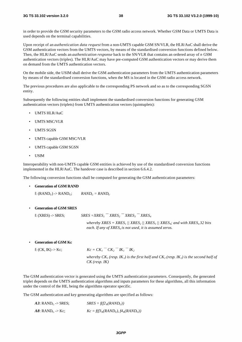
3GPP
3G TS 33.102 V3.2.0 (1999-10)383G TS 33.102 version 3.2.0
in order to provide the GSM security parameters to the GSM radio access network. Whether GSM Data or UMTS Data is used depends on the terminal capabilities.
Upon receipt of an authentication data request from a non-UMTS capable GSM SN/VLR, the HLR/AuC shall derive the GSM authentication vectors from the UMTS vectors, by means of the standardised conversion functions defined below. Then, the HLR/AuC sends an authentication response back to the SN/VLR that contains an ordered array of n GSM authentication vectors (triples). The HLR/AuC may have pre-computed GSM authentication vectors or may derive them on demand from the UMTS authentication vectors.
On the mobile side, the USIM shall derive the GSM authentication parameters from the UMTS authentication parameters by means of the standardised conversion functions, when the MS is located in the GSM radio access network.
The previous procedures are also applicable to the corresponding PS network and so as to the corresponding SGSN entity.
Subsequently the following entities shall implement the standardised conversion functions for generating GSM authentication vectors (triplets) from UMTS authentication vectors (quintuplets):
• UMTS HLR/AuC
• UMTS MSC/VLR
• UMTS SGSN
• UMTS capable GSM MSC/VLR
• UMTS capable GSM SGSN
• USIM
Interoperability with non-UMTS capable GSM entities is achieved by use of the standardised conversion functions implemented in the HLR/AuC. The handover case is described in section 6.6.4.2.
The following conversion functions shall be computed for generating the GSM authentication parameters:
• Generation of GSM RAND
f: (RANDU) -> RANDG; RANDG = RANDU
• Generation of GSM SRES
f: (XRES) -> SRES; SRES =XRES1 ⊕ XRES2 ⊕ XRES3 ⊕ XRES4
whereby XRES = XRES1 || XRES2 || XRES3 || XRES4; and with XRESn 32 bits each. If any of XRESn is not used, it is assumed zeros.
• Generation of GSM Kc
f: (CK, IK) -> Kc; Kc = CK1 ⊕ CK2 ⊕ IK1 ⊕ IK2
whereby CK1 (resp. IK1) is the first half and CK2 (resp. IK2) is the second half of CK (resp. IK)
The GSM authentication vector is generated using the UMTS authentication parameters. Consequently, the generated triplet depends on the UMTS authentication algorithms and inputs parameters for these algorithms, all this information under the control of the HE, being the algorithms operator specific.
The GSM authentication and key generating algorithms are specified as follows:
A3: RANDG -> SRES; SRES = f(f2K(RANDU))
A8: RANDG -> Kc; Kc = f(f3K(RANDU), f4K(RANDU))

3GPP
3G TS 33.102 V3.2.0 (1999-10)393G TS 33.102 version 3.2.0
6.8.2 Interoperability for GSM users
The mechanism described here achieves intersystem operability between UMTS and GSM networks allowing secure interoperation between both networks for GSM users (SIM). The following figure illustrates the different scenarios of interoperability for 2G users:

3GPP
3G TS 33.102 V3.2.0 (1999-10)403G TS 33.102 version 3.2.0
Figure 15: Interoperability for GSM Users
The GSM authentication parameters are generated by the GSM HLR/AuC and the SIM by use of the home operator specified algorithms for this purpose.
Upon receipt of an authentication data request from any SN/VLR (UMTS or GSM), the HLR/AuC sends an ordered array of n GSM authentication vectors (triplets) to the SN/VLR.
If the UMTS MSC/VLR is able to handle UMTS radio access network, the MSC/VLR shall be able to derive a UMTS authentication vector from the received GSM authentication vector, by means of the standardised conversion functions defined below, in order to provide the UMTS security parameters to the UMTS radio access network.
On the mobile side, the UE shall derive the UMTS authentication parameters from the GSM authentication parameters generated by the SIM by means of the standardised conversion functions, when the MS is located in the UMTS radio access network.
The previous procedures are also applicable to the corresponding PS network and so as to the corresponding SGSN entity.
Subsequently the following entities shall implement the standardised conversion functions for generating UMTS authentication parameters from GSM authentication vectors (triplets):
• UMTS MSC/VLR
• UMTS SGSN
• UE
The following conversion functions shall be computed for generating the UMTS authentication parameters:
• Generation of UMTS RAND
f: (RANDG) -> RANDU; RANDU = RANDG
GSM HLR/AuC
UMTS MSC/VLR
GSM MSC/VLR Non-UMTS
capable
UMTS Access
Network
GSM AV (RAND, SRES, Kc)
GSM Data (RAND, Kc)
UMTS Data (RAND, CK, IK)
GSM Data (RAND, Kc)
GSM AV (RAND, SRES, Kc)
GSM MSC/VLR
UMTS capable
GSM Data (RAND, Kc)
GSM AV (RAND, SRES, Kc)
GSM Access
Network
GSM Access
Network
GSM Access
Network
3GPP
3G TS 33.102 V3.2.0 (1999-10)413G TS 33.102 version 3.2.0
• Generation of UMTS XRES
f: (SRES) -> XRES; XRES = SRES
• Generation of UMTS CK
f: (Kc) -> CK; CK = 0..0 || Kc
• Generation of UMTS IK
f: (Kc) -> IK; IK = Kc || Kc
• Generation of UMTS AUTN
The authentication token AUTN is not used for GSM users.
The UMTS authentication vector is generated using the GSM authentication parameters. Consequently, the generated quintuplet depends on the GSM authentication algorithms and inputs parameters for these algorithms, all this information under the control of the HE, being the algorithms operator specific.
A GSM user should receive the security level provided by the home network. The effective encryption key length used in UMTS radio access network is the GSM Kc length, provided by the HE; Integrity protection is provided by using the GSM encryption key; and the AUTN parameter is not used.
The UMTS authentication and key generating algorithms are specified as follows:
f2: RANDu -> XRES; XRES =A3(RANDG)
f3: RANDu -> CK; CK = 0..0 || A8(RANDG)
f4: RANDu -> IK; IK = A8(RANDG) || A8(RANDG)
f: (RANDu, SEQ, AK, MAC) -> AUTN; Parameter not used
7 Network domain security mechanisms This subclause describes mechanisms for establishing secure signalling links between network nodes, in particular between SN/VLRs and HE/AuCs. Such procedures may be incorporated into the roaming agreement establishment process.
7.1 Overview of Mechanism
The proposed mechanism consists of three layers.
7.1.1 Layer I
Layer I is a secret key transport mechanism based on an asymmetric crypto-system and is aimed at agreeing on a symmetric session key for each direction of communication between two networks X and Y.
[Note: For secure transmis sion of sensitive data between elements of one and the same network operator only Layer II and Layer III will be involved. In this case Layer I can be dropped. There will also be only one symmetric key in this case, to be used for communication between network elements of one network operator in both directions.]
The party wishing to send sensitive data initiates the mechanism and chooses the symmetric session key it wishes to use for sending the data to the other party. The other party shall choose a symmetric session key of its own, used for sending data in the other direction. This second key shall be transported immediately after the first key has been successfully transported. The session symmetric keys are protected by asymmetric techniques. They are exchanged between certain elements called the Key Administration Centres (KACs) of the network operators X and Y. The format of the Layer I transmissions is based on ISO/IEC 11770-3: Key Management – Mechanisms using Asymmetric
3GPP
3G TS 33.102 V3.2.0 (1999-10)423G TS 33.102 version 3.2.0
Techniques [10]. Public Keys may be exchanged between a pair of network operators when setting up their roaming agreement (manual roaming) or they may be distributed by a TTP e.g. in case of automatic roaming.
Note: In the case of manual roaming no general PKI is required.
Note: For the transmission of the messages, no special assumptions regarding the transport protocol are made, a possible example would be IP.
7.1.2 Layer II
In Layer II the agreed symmetric keys for sending and receiving data are distributed by the KACs in each network to the relevant network elements. For example, an AuC will normally send sensitive authentication data to VLRs belonging to other networks and will therefore get a session key from its KAC. Layer II is carried out entirely inside one operator's network. It is clear that the distribution of the symmetric keys to the network elements must be carried out in a secure way, as not to compromise the whole system. Therefore, in Annex E a mechanism for distributing the keys, which very similar to that of Layer I, is proposed for Layer II.
7.1.3 Layer III
Layer III uses the distributed symmetric keys for securely exchanging sensitive data between the network elements of one operator (internal use) or different operators (external use) by means of a symmetric encryption algorithm. A block cipher (e.g. BEANO, which has been developed by ETSI SAGE [11]) shall be used for this purpose, as defined in 3G TS 33.105. The encrypted (resp. authenticity/integrity-protected) messages will be transported via the MAP protocol.
7.1.4 General Overview
Figure 16 provides an overview of the whole mechanism. Note that the messages are not fully specified in this figure. Rather, only the "essential" parts of the messages are given. More details on the format of the messages in the single layers will be provided in subsequent chapters.
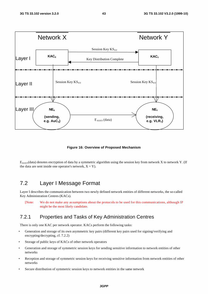
3GPP
3G TS 33.102 V3.2.0 (1999-10)433G TS 33.102 version 3.2.0
Figure 16: Overview of Proposed Mechanism
E KSXY(data) denotes encryption of data by a symmetric algorithm using the session key from network X to network Y. (If the data are sent inside one operator's network, X = Y).
7.2 Layer I Message Format
Layer I describes the communication between two newly defined network entities of different networks, the so-called Key Administration Centres (KACs).
[Note: We do not make any assumptions about the protocols to be used for this communications, although IP might be the most likely candidate.
7.2.1 Properties and Tasks of Key Administration Centres
There is only one KAC per network operator. KACs perform the following tasks:
• Generation and storage of its own asymmetric key pairs (different key pairs used for signing/verifying and encrypting/decrypting, cf. 7.2.2)
• Storage of public keys of KACs of other network operators
• Generation and storage of symmetric session keys for sending sensitive information to network entities of other networks
• Reception and storage of symmetric session keys for receiving sensitive information from network entities of other networks
• Secure distribution of symmetric session keys to network entities in the same network
Key Distribution Complete
Session Key KSXY
Network X Network Y
KACX Layer I
Layer II
Layer III NEX
(sending, e.g. AuCX)
NEY
(receiving, e.g. VLRY) E KSXY (data)
Session Key KSXY
KACY
Session Key KSXY
3GPP
3G TS 33.102 V3.2.0 (1999-10)443G TS 33.102 version 3.2.0
Due to these sensitive tasks, a KAC has to be physically secured.
7.2.2 Transport of Session Keys
The transport of session keys in Layer I is based on asymmetric cryptographic techniques (cf. [10]).
[Note: Public key certificates shall be included in Text3 if required.]
In order to establish a symmetric session key with version no. i to be used for sending data from X to Y, the KACX sends a message containing the following data to the KACY:
EPK(Y) {X||Y||i||KSXY(i)||RNDX||Text1||DSK(X)(Hash(X||Y||i||KSXY(i)||RNDX||Text1))||Text2}||Text3
The reasons for this message format are as follows:
- Encrypting the message with the public key used for encrypting of the receiving network Y provides message confidentiality, while decrypting the message body with the private key used for signing of the sending network X provides message integrity and authenticity.
- X includes RNDX to make sure that the message contents contains some random data before signing.
[Note: The hash function used shall be collision-resistant and have the one-way property.]
The symmetric session keys KSXY(i) should be periodically updated by this process, thereby moving on to KSXY(i+1). For each new session key KSXY i is incremented by one.
After having successfully decrypted the key transport message and having verified the digital signature of the sending network, including the hash value, and having checked the received i the receiving network starts Layer II activities.
If anything goes wrong, e.g. computing the hash value of X||Y| |i||KSXY(i)||RNDX||Text1 does not yield the expected result, a RESEND message should be sent by Y to X in the form
RESEND||Y||X
Y shall reject messages with i smaller or equal than the currently used i.
After having successfully distributed the symmetric session key received by network X to its own network entities, network Y sends to X a Key Distribution Complete Message. This is an indication to KACX to start with the distribution of the key to its own entities, which can then start to use the key immediately. The message takes the form
KEY_DIST_COMPLETE||Y||X||i||RNDY||DSK(Y)(Hash(KEY_DIST_COMPLETE||Y||X||i||RNDY)
where i indicates the distributed key and RNDY is a random number generated by Y. The digital signature is appended for integrity and authenticity purposes. Y includes RNDY to make sure that the message contents determined by X will be modified before signing.
Since most of the signalling messages to be secured are bidirectional in character, immediately after successful completion the procedure described here shall be repeated, now with Y choosing a key KSYX(i) to be used in the reverse direction, and X being the receiving party. Thereby keys for both directions are established.
7.3 Layer II Message Format
It shall be stressed here once again that the distribution of the symmetric session keys, which has to be performed in Layer II, must be done securely. For a detailed proposal which is based on the asymmetric key transport mechanism of Layer I, see Annex E.
In order to ensure that no network element starts enciphering with a key that not all potentially corresponding network elements have received yet, the following approach is suggested:
The distribution of the session keys KSXY in network X having initiated the Layer I message exchange should not begin before the Key Distribution Complete Message from the receiving network Y has been received by KACX in Layer I. As soon as a network element of X has received a session key KSXY, it may start enciphering with this key.
A similar statement holds if the transported session keys are used internally only: In this case, all network elements of X

3GPP
3G TS 33.102 V3.2.0 (1999-10)453G TS 33.102 version 3.2.0
should get the symmetric session keys KSXX for internal use as decryption keys (marked with flag RECEIVED) first; if all network elements of X have acknowledged that they have recovered these keys, the KACX sends the same key KSXX again as encryption keys (marked with flag SEND). Again, as soon as a network element of X has received an encryption key (marked with flag SEND), it may start enciphering with this key.
7.4 Layer III Message Format
7.4.1 General Structure of Layer III Messages
Layer III messages are transported via the MAP protocol, that means, they form the payload of a MAP message after the original MAP message header. For Layer III Messages, three levels of protection (or protection modes) are defined providing the following security features:
Protection Mode 0: No Protection
Protection Mode 1: Integrity, Authenticity
Protection Mode 2: Confidentiality, Integrity, Authenticity
[Note: GTP based transmission data will also contain sensitive data. This data will require an equal level of security (e.g. authentication parameters, subscriber profile information, etc.). The specifications will extended to address GTP based transmissions using industry standard techniques (such as IPSEC) where appropriate. The possibility of extending these mechanisms to secure CAP/INAP signalling is also being investigated.]
Layer III messages consists of a Security Header and the Layer III Message Body that is protected by the symmetric encryption algorithm, using the symmetric session keys that were distributed in layer II. Layer III Messages have the following structure:
Security Header
Layer III Message Body
In all three protection modes, the security header is transmitted in cleartext. It shall comprise the following information:
- protection mode;
- other security parameters (if required, e.g. IV, Version No. of Key Used, Encryption Algorithm Identifier, Mode of Operation of Encryption Algorithm, etc.).
Both parts of the Layer III messages, security header and message body, will become part of the "new" MAP message body. Therefore, the complete "new" MAP messages take the following form in this proposal:

3GPP
3G TS 33.102 V3.2.0 (1999-10)463G TS 33.102 version 3.2.0
MAP Message
Header
MAP Message Body
Layer III Message
MAP Message
Header
Security
Header
Layer III Message Body
Like the security header, the MAP message header is transmitted in cleartext. In protection mode 2 providing confidentiality, the Layer III Message Body is essentially the encrypted "old" MAP message body. For integrity and authenticity, an encrypted hash calculated on the MAP message header, security header and the "old" MAP message body in cleartext is included in the Layer III Message Body in protection modes 1 and 2. In protection mode 0 no protection is offered, therefore the Layer III Message Body is identical to the "old" MAP message body in cleartext in this case.
In the following subchapters, the contents of the Layer III Message Body for the different protection modes will be specified in greater detail.
7.4.2 Format of Layer III Message Body
7.4.2.1 Protection Mode 0
Protection Mode 0 offers no protection at all. Therefore, the Layer III message body in protection mode 0 is identical to the original MAP message body in cleartext.
7.4.2.2 Protection Mode 1
The message body of Layer III messages in protection mode 1 takes the following form:
Cleartext||TVP||EKSXY(i)(Hash(MAP Header||Security Header||Cleartext||TVP))
where "Cleartext" is the message body of the original MAP message in cleartext.
Authentication of origin is achieved by encrypting the hash value of the cleartext, since only a network element knowing KSXY(i) can encrypt in this way. Message integrity and validation is achieved by hashing and encrypting the cleartext.
[Note: The case X=Y, i.e. only one key for sending and receiving, corresponds to internal use inside network X.]
Note that protection mode 1 is compatible to the present MAP protocol, since everything appended to the cleartext may be ignored by a receiver incapable of decrypting.
7.4.2.3 Protection Mode 2
The Layer III Message Body in protection mode 2 takes the following form:

3GPP
3G TS 33.102 V3.2.0 (1999-10)473G TS 33.102 version 3.2.0
EKSXY(i)(Cleartext||TVP||Hash(MAP Header||Security Header||Cleartext||TVP))
where "Cleartext" is the original MAP message in cleartext.
Message confidentiality is achieved by encrypting with the session key. This also provides for authentication of origin, since only a network element knowing KSXY(i) can encrypt in this way. Message integrity and validation is achieved by hashing the cleartext. TVP is a random number that avoids traceability.
[Note1: There is need for replay protection of Layer III messages; this is for further study. By making use of a TVP as timestamp (perhaps derived from an overall present master time) this could be achieved.]
[Note2: In protection mode 2, the original MAP message body will be encrypted in order to achieve confidentiality. For integrity and authenticity, an encrypted hash calculated on the MAP message header and body in cleartext (i.e. the original MAP message) is appended to the messages in protection mode 1 and 2. All protection modes need a security header to be added. When implementing these changes, care has to be taken that the maximum length of a MAP message (approx. 250 byte) is not exceeded by the protected MAP messages of Layer III, otherwise substantial changes to the underlying SS7 protocol levels (TCAP and SCCP) would have to be made.]
7.5 Mapping of MAP Messages and Modes of Protection
The network operator should be able to assign the mode of protection to each MAP message in order to adapt the level of protection according to its own security policy. Guidance may be obtained from the SS7 Signalling Protocols Threat Analysis [12].
8 Application security mechanisms
8.1 Secure messaging between the USIM and the network
This clause will specify the structure of the secured messsages in a general format so that they can be used over a variety of transport channels between an entity in a 3GMS network and an entity in the USIM. The sending/receiving entity in the 3GMS network and in the USIM are responsible for applying the security mechanisms to application messages as defined to provide the security features identified in 5.4.1.
Note: A joint 3GPP TSG-SA ‘Security’/3GPP TSG-T ‘USIM’ working group may be required to progress this issue.
8.2 Network-wide user traffic confidentiality
8.2.1 Introduction
Subclause 6.6 specifies how signalling information, user identity and user traffic information may be confidentiality protected by providing a protected mode of transmission on dedicated channels between the UE and the RNC. Network-wide confidentiality is an extension of this security feature which provides a protected mode of transmission on user traffic channels across the entire network. This gives users assurance that their traffic is protected against eavesdropping on every link within the network, i.e. not just the particularly vulnerable radio links in the access network, but also on the fixed links within the core network.
If network-wide confidentiality of user traffic is provided then access link confidentiality of user traffic between UE and RNC shall be replaced with the network-wide service. Access link confidentiality of signalling information and user identity between UE and RNC shall be applied regardless of whether or not the network-wide user traffic confidentiality service is applied.

3GPP
3G TS 33.102 V3.2.0 (1999-10)483G TS 33.102 version 3.2.0
Note: The exact architectural placement of the network-wide encryption function is for further study. This may have an impact on whether network-wide encryption replaces or supplements access link encryption.
A lawful interception interface may be implemented according to TS33.107 regardless of whether or not network-wide confidentiality is applied by the network. It shall be possible to remove any network-wide confidentiality protection within the core network to provide access to plaintext user traffic at the lawful interception interface.
Network-wide confidentiality shall be provided by protecting transmissions on user traffic channels using a synchronous stream cipher. This involves the specification of a standard method for ciphering user traffic on a network-wide basis (clause 8.2.2) and a standard method for managing the ciphering key required at the end points of the protected channel (clause 8.2.3).
8.2.2 Ciphering method
The network-wide encryption algorithm shall be a synchronous stream cipher. It shall be possible to use the same algorithm UEA for access link encryption and network-wide encryption.
The network-wide synchronous stream cipher shall contain a key stream generator which shall have two inputs: the network-wide cipher key (ECK) and an initialisation value (IV). The plaintext shall be encrypted using the key stream by applying an exclusive-or operation to the plaintext on a bit per bit basis to generate the ciphertext. The decryption operation shall involve applying the same key stream to the ciphertext to recover the plaintext.
Synchronisation of the key stream shall be achieved using the initialisation value. Synchronisation information shall be available at both end points of the communication and shall be used to maintain alignment of the key stream. Protection against replay of user traffic shall be achieved through the use of a time variable initialisation vector combined with a time variable cipher key.
Note: The stream cipher does not protect against bit toggling so other mechanisms must be used if this type of integrity protection is required on user traffic.
For encryption of voice traffic then Transcoder Free Operation (TFO) shall be used between the two end points such that the structure and ordering of the transmitted data shall be maintained with the same boundary conditions at each end of the link.
Note: In the initial phases of 3GPP, transcoder free operation may only be possible for user traffic channels which terminate within the same serving network. Furthermore, TFO may only be possible if the entire communication path is within the same serving network. Thus, in non optimal routing cases where the tromboning effect occurs, TFO may not be available, even if the traffic channel terminates within the same serving network.
For encryption of data traffic a transparent data service shall be used between the two end points such that the structure and ordering of transmitted data shall be maintained with the same boundary conditions at each end of the link.
To satisfy lawful interception requirements it must be possible to decrypt network-wide encrypted traffic within the core network to provide access to plaintext user traffic. Thus decryption facilities (and the network-wide cipher key) shall be available in the core network for lawful interception reasons. If transcoder free operation is used on voice traffic channels, transcoders shall be available in the core network for lawful interception reasons whether or not network-wide encryption is provided.
For further study:
- Specification of encryption synchronisation mechanism;
- Adaptation of TFO voice traffic channels for network-wide confidentiality;
- Adaptation of data traffic channels for network-wide confidentiality;
- The ability to terminate network-wide encryption at network gateways for inter-network user traffic channels;
- The ability to handle multiparty calls, explicit call transfer and other supplementary services;
- Network-wide encryption control – algorithm selection, mode selection, user control

3GPP
3G TS 33.102 V3.2.0 (1999-10)493G TS 33.102 version 3.2.0
8.2.3 Key management
Signalling links within the network shall be protected on a link-by-link basis. In particular, the UE to RNC signalling links shall be protected using access link keys (see clause 6) and core network signalling links shall be protected using network security domain keys (see clause 7). If network-wide encryption is provided across serving network boundaries (which requires that inter-network TFO is available) then the signalling links requiring protection will cross network boundaries.
Note: If network-wide encryption is provided across serving network boundaries then the two serving networks may not be roaming partners yet they still must be able to protect inter-network signalling by establishing appropriate keys.
The key management scheme for network-wide encryption involves establishing a network-wide cipher key between the end points of the traffic channel. It should not be possible to obtain this key by eavesdropping on any transmission links within the network.
Note: However, it is be possible to obtain the network-wide key by compromising certain nodes within the network (e.g. nodes where link encryption terminates).
To satisfy lawful interception requirements it shall be possible to decrypt network-wide encrypted traffic within the core network to provide access to plaintext user traffic. Thus, the network-wide cipher key (and decryption facilities) shall be available in the core network for lawful interception reasons.
The key management scheme is illustrated in the diagram below.
MSC/VLRa
MSC/VLRb
UEa UEb
RNCa RNCb
ECKCa
ECKC b
Signalling links protected by link encryption
User traffic links protected by network-wide encryption
ECKCb
ECKC a
ECK=f(ECKCa,ECKCb)
ECK=f(ECKCa,ECKCb)
Figure 17: Key management scheme for network-wide encryption
In addition to the access link cipher and integrity keys, the USIM and the MSC/VLR shall also establish a network-wide cipher key component ECKC as part of the authentication and key agreement procedure (clause 6.3). This key component will be used to generate the network-wide cipher key ECK.
As part of establishing a network-wide encrypted connection, MSC/VLRa and MSC/VLRb shall exchange network-wide cipher keys components for UEa and UEb. MSC/VLRa passes ECKCb to UEa, while MSC/VLRb passes ECKCa to UEb. At each end the access link key is transmitted to the UE over signalling channels which are protected using the access link cipher keys CK. When each UE has received the other party’s network-wide cipher key component, the network-wide cipher key ECK shall be calculated as a function of ECKCa and ECKCb.

3GPP
3G TS 33.102 V3.2.0 (1999-10)503G TS 33.102 version 3.2.0
The key management scheme satisfies the lawful interception requirement since ECK can be generated by MSC/VLRa or MSC/VLRb and then used by decryption facilities in the core network to provide plaintext user traffic at the lawful interception interface.
For further study:
- Specification of mechanism to exchange network-wide cipher key components.
- The ability to terminate network-wide cipher key management at network gateways for inter-network user traffic channels.
8.3 IP security
[ffs]

3GPP
3G TS 33.102 V3.2.0 (1999-10)513G TS 33.102 version 3.2.0
Annex A: Requirements analysis [In this part of the document we will address the question "do the features meet the requirements?"]

3GPP
3G TS 33.102 V3.2.0 (1999-10)523G TS 33.102 version 3.2.0
Annex B (Informative): Enhanced user identity confidentiality
This mechanism allows the identification of a user on the radio access by means of the permanent user identity encrypted by means of a group key. The mechanism described here can be used in combination with the mechanism described in 6.2 to provide user identity confidentiality in the event that the user not known by means of a temporary identity in the serving network.
The mechanism assumes that the user belongs to a user group with group identity GI. Associated to the user group is a secret group key GK which is shared between all members of the user group and the user’s HE, and securely stored in the USIM and in the HE.
The mechanism is illustrated in Figure B.1.
MS SN/VLR HE
User identity request
HE-id || GI || EMUI
GI || EMUI
IMUI
Generate TVPEMUI := f6GK (TVP || IMUI)
Retrieve GKTVP || IMUI := f7GK (EMUI)
Figure B.1: Identification by means of the IMUI encrypted by means of a group key
The user identity procedure is initiated by the visited VLR. The visited VLR requests the user to send its permanent user identity.
Upon receipt the user generates a time variant parameter TVP. The user encrypts the time variant parameter TVP and the IMUI with enciphering algorithm f6 and his group key GK. The TVP prevents traceability attacks. The user sends a response to the VLR that includes the HE identity, the group identity GI and the encrypted mobile user identity (EMUI).
Upon receipt of that response the SN/VLR should resolve the user’s HE address from HE-identity and forwards the group identity GI and the user’s EMUI to the user’s HE.
Upon receipt the HE retrieves the group key GK associated with the group identity GI. The HE then decrypts EMUI with the deciphering algorithm f7 (f7 = f6-1) and the group key GK and retrieves TVP and IMUI. The HE then sends the IMUI in a response to the visited SN/VLR.
3GPP
3G TS 33.102 V3.2.0 (1999-10)533G TS 33.102 version 3.2.0
Annex C: Management of sequence numbers This annex is devoted to the management of sequence numbers for the authentication and key agreement protocol.
C.1 A mechanism using two individual counters on each side
This is the mechanism included in the main body of this specification.
C.2 A mechanism using a global counter in the HE and two counters in the MS
In this mechanism the HLR/AuC keeps track of time, while the USIM keeps track of a counters for PS mode SQNMS/PS and a counter for CS mode SQNMS/CS.
The HLR/AuC may for instance use as a sequence number the number of seconds t that have elapsed since the start of the year 2000 (GMT). Then, a 32-bit sequence number will suffice for 136 years of operation. When an array of n authentication vectors is generated, the values t, t+1, …, t+n-1 could be used.
At the user end, SQN is treated as in the mechanism described under C.1.
Note 1: When using a time-value to generate sequence numbers it may not be necessary to conceal the sequence number to avoid user identification.
Note 2: The re-synchronisation procedure is not required in this case, as time can be recovered from any source.
C.3 A mechanism using one individual counter in the HE and a window in the USIM
In this mechanism the sequence numbers are generated as in the mechanism described in C.1. However, the USIM verifies the freshness differently. In addition to the highest sequence number SQNMS it has accepted, it keeps track of which values in a window [SQNMS – w, SQNMS) it has already accepted... If a sequence number is received that is higher than SQNMS – w and has not been accepted before, it is accepted and the window is updated accordingly.
Using this mechanism, it is not required that a previously visited SN/VLR deletes the unused authentication vectors when a user de-registers from the serving network. Retaining the authentication vectors for use when the user returns later may be more efficient as regards signalling when a user abroad switches a lot between two serving networks.
Note: When a VLR uses fresh authentication vectors obtained during a previous visit of the user, the USIM can reject them although they have not been used before (because w is finite). Rejection of a sequence number can therefore occur in normal operation, i.e., it is not necessarily caused by (malicious) replay or a database failure.

3GPP
3G TS 33.102 V3.2.0 (1999-10)543G TS 33.102 version 3.2.0
C.4 A mechanism using a (partly) global counter in the HE and a list in the USIM
In this mechanism the sequence numbers are generated with one of the mechanisms described in C.2 and in C.6. However, the USIM verifies the freshness differently. Instead of keeping track of the highest sequence number SQNMS only, it keeps track of an ordered list of the b highest values it has accepted,. If a sequence number is received that is lower than or equal to the lowest value SQNLO in that list, it is rejected. If however, a sequence number is received that is higher than the lowest entry in the list, but is not in the list it is accepted and included in the list. The lowest value SQNLO in the list is then deleted.
Using this mechanism, it is not required that a previously visited SN/VLR deletes the unused authentication vectors when a user de-registers from the serving network. Retaining the authentication vectors for use when the user returns later may be more efficient as regards signalling when a user abroad switches a lot between two serving networks.
Note: When a VLR uses fresh authentication vectors obtained during a previous visit of the user, the USIM can reject them although they have not been used before (because b is finite). Rejection of a sequence number can therefore occur in normal operation, i.e., it is not necessarily caused by (malicious) replay or a database failure.
C.5 A mechanism using two individual counters on each side offering protection against wrap around of counters
The basic idea of the alternative sequence number handling is that the MS will not accept arbitrary jumps in sequence numbers. The sequence number SQN is accepted by the MS if and only if the following holds for some ∆:
SQN > SQNMS (as for alternative C.1) and SQN - SQNMS < ∆ .
This means that SQNMS can reach its maximum value only after a minimum of SQNmax/∆ successful authentications have taken place.
Conditions on ∆ :
(1) ∆ shall be sufficiently large so that the MS will not receive any SQN with SQN - SQNMS ≥ ∆ if the HE/AuC functions correctly.
(2) SQNmax /∆ shall be sufficiently large to prevent that SQNMS ever reaches SQNmax during the lifetime of the USIM.
C.6 A generalised scheme for sequence number management
This section describes the use of generalised sequence numbers which have an individual and a global component.
(1) The sequence number consists of two concatenated parts SQN = SQN1 || SQN2. SQN1 represents the most significant bits of SQN, and SQN2 represents the least significant bits of SQN.
(2) There are counters SQNMS and SQNHE in the MS and the HE respectively. Both parts of SQN are stored by these counters. SQNHE is an individual counter, i.e. there is one per user.
(3) There is a global counter, e.g. a universal clock with an appropriate time granularity (e.g. seconds elapsed since the start of the system). For short we call the value of this global counter at any one time GLC. If GLC is taken from a universal clock it is computed mod 2n where n is the length of GLC and of SQN2 in bits.
(4) When the HE needs a new sequence number SQN to create a new authentication vector, HE retrieves the (user-specific) value of SQNHE = SQN1HE || SQN2HE from the database. If SQN2HE < GLC then HE sets SQN = SQN1HE || GLC. If SQN2HE ≥ GLC then HE sets SQN = (SQN1HE +1) || GLC. Then SQNHE is reset to SQN.

3GPP
3G TS 33.102 V3.2.0 (1999-10)553G TS 33.102 version 3.2.0
(5) The sequence number SQN is accepted by the USIM if and only if SQN >SQNMS holds.
(6) If the mechanism described in Annex C.4 (lists of sequence numbers in the USIM) is used and if SQNLO denotes the lowest sequence number in the list then (5) becomes:
The sequence number SQN is now accepted by the USIM if and only if SQN >SQNLO holds and SQN is not in the list.
(7) If the mechanism described in Annex C.5 (protection against counter wrap-around) is employed then (5) becomes:
The sequence number SQN is now accepted by the USIM if and only if SQN>SQNMS and SQN - SQNMS< ∆ hold.
(8) If both the mechanisms described in Annexes C.4 and C.5 are employed and if SQNHI denotes the highest sequence number in the list then (5) becomes:
The sequence number SQN is now accepted by the USIM if and only if SQN>SQNLO and SQN – SQNHI < ∆ hold and SQN is not in the list.
When parameters are appropriately chosen then this use of sequence numbers is compatible with the re-synchronisation procedure described in section 6.3.5 and the protection against wrap around of counters described in Annex C.5, and it is not required to conceal this type of sequence numbers.

3GPP
3G TS 33.102 V3.2.0 (1999-10)563G TS 33.102 version 3.2.0
Annex D: A mechanism for authentication based on a temporary key
D.1 Authentication based on a Temporary Key
D.1.1 General
The mechanism described here achieves mutual authentication and key agreement between the USIM and the AuC in the user’s HE, showing knowledge of a secret key K which is shared between and available only to these two parties. The temporary key generated during the protocol is shared with the visited SN/VLR, and can be used subsequently with the local authentication and session key agreement protocol described in section D.2 or with the other local authentication mechanisms described in section 6.5. Additionally, session keys for the first session are created during the protocol.
The method was chosen in such a way as to reduce signalling between the HE and the SN/VLR. The method is composed of a mutually authenticated challenge/response protocol with key agreement.
An overview of the mechanism is shown in Figure D.1.
When the mobile first requests service from the SN/VLR, a random seed RSu created by the user (USIM or terminal) is included in the request message. The message including RSu is forwarded to the HE/AuC, which generates its own random challenge RSn. An authentication vector is returned to the SN/VLR. The vector contains {RSn, RES1, XRES2, KT}, where RES1 is the response to the user’s challenge, XRES2 is the response to the network’s challenge which is expected from the user, and KT is the temporary authentication key shared with the SN/VLR. The network’s challenge RSn and the network authentication response RES1 are sent to the MS. If the MS verifies RES1, thereby authenticating the identity of the network, it responds with RES2 and generates the new temporary key KT. The SN/VLR then verifies that RES2 equals XRES2, thereby authenticating the identity of the USIM, and stores the new temporary key KT. Furthermore, both the USIM and the SN/VLR immediately use KT with the random seeds RSu and RSn to generate the first session keys CK and IK. The established keys CK and IK will then be transferred by the USIM and the SN/VLR to the entities which perform ciphering and integrity functions.
The SN/VLR can offer secure service to the USIM without reference to the home system HE/AuC by using the temporary key KT. This local authentication mechanism is described in section D.2.
SN/VLR HE/AuC
RSn, RES1, XRES2, KT
Generate temporaryauthentication key,
and signed responses.
Authenticationinformation request, RSu
Store temporaryauthentication key
User
RSn, RES1
RES2
Compute temporarykey, XRES1, and
RES2.
Compare RES2 withXRES2
RSu
Compare RES1 withXRES1.
Compute SessionKeys CK, IK. Compute session
keys CK,IK ** Session keys CK and IK may optionally
be computed at the HE.
Figure D.1: Authentication
3GPP
3G TS 33.102 V3.2.0 (1999-10)573G TS 33.102 version 3.2.0
The authenticating parties shall be the AuC of the user’s HE (HE/AuC) and the USIM in the user’s mobile station. The mechanism consists of the following procedures:
A procedure to generate a new temporary authentication key and session keys, and distribute the temporary authentication key from the HE/AuC to the SN/VLR. This procedure is described in D.1.2. The SN/VLR is assumed to be trusted by the user’s HE to handle authentication information securely. It is also assumed that the intra-system links between the SN/VLR to the HE/AuC are adequately secure. Mechanisms to secure these links are described in clause 7. It is further assumed that the user trusts the HE.
A procedure to distribute the temporary authentication key from a previously visited VLR to the newly visited VLR. This procedure is described in D.1.3. It is also assumed that the links between SN/VLRs are adequately secure. Mechanisms to secure these links are described in clause 7.
D.1.2 Temporary Key Generation with Session Key Agreement
The services provided by this mutually authenticated key agreement protocol are:
- the SN/VLR authenticates the MS;
- the MS verifies that the SN/VLR is allowed to offer it services on behalf of its HE;
- the MS and the HE establish a new temporary authentication key with freshness guarantees to both parties;
- the HE distributes this temporary key to the SN/VLR for subsequent use in local authentication protocols; and,
- the MS and the SN/VLR establish new cipher and integrity keys with freshness guarantees to both parties.
The procedure is illustrated in Figure D.2.
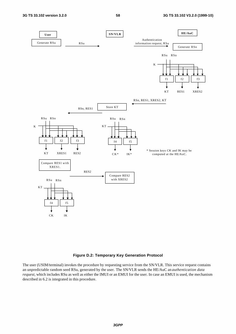
3GPP
3G TS 33.102 V3.2.0 (1999-10)583G TS 33.102 version 3.2.0
SN/VLR HE/AuC
RSn, RES1, XRES2, KT
Authenticationinformation request, RSu
User
RSn, RES1
RES2Compare RES2
with XRES2
RSu
Compare RES1 withXRES1.
KT RES1 XRES2
f1
K
RSu
f2
RSn
f3
RSn
C K * IK*
f4
KT
RSu
f5
RSn
KT XRES1 RES2
f1
K
RSu
f2 f3
Store KT
* Session keys CK and IK may becomputed at the HE/AuC.
Generate RSuGenerate RSn
RSn
CK IK
f4
KT
RSu
f5
Figure D.2: Temporary Key Generation Protocol
The user (USIM/terminal) invokes the procedure by requesting service from the SN/VLR. This service request contains an unpredictable random seed RSu, generated by the user. The SN/VLR sends the HE/AuC an authentication data request, which includes RSu as well as either the IMUI or an EMUI for the user. In case an EMUI is used, the mechanism described in 6.2 is integrated in this procedure.
3GPP
3G TS 33.102 V3.2.0 (1999-10)593G TS 33.102 version 3.2.0
Upon the receipt of the authentication data request from the SN/VLR, the HE/AuC generates the authentication vector. To generate an authentication vector AV the HE/AuC generates an unpredictable random value RSn. Subsequently the following values are computed:
- a temporary key KT = f1K(PAR1 || RSu || RSn) where f1 is a key generating function.
- an authentication response RES1 = f2K (PAR2 || RSu || RSn) where f2 is a (possibly truncated) MAC function.
- an expected response XRES2 = f3K (PAR3 || RSu || RSn) where f3 is a (possibly truncated) MAC function.
Note 1: The need for f2 and f3 to use a long-term key different from K is ffs.
Note 2: It is also ffs in how far the functions f1, ..., f5 need to differ and how they may be suitably combined.
Note 3: PAR1, ..., PAR5 are different fixed initial values which may be used when similar or identical functions are used for f1, ..., f5. The need for the inclusion of PAR1, ... PAR5 is ffs. When omitted they may be thought of as being integrated in the definition of the functions f1, ..., f5 respectively.
These authentication parameters are used to construct an ordered array of authentication vectors for the user consisting of {RSn, RES1, XRES2, KT}.
The HE/AuC sends the requested authentication vector to the SN/VLR in a response message.
The serving system SN/VLR may generate the session keys locally, or they may be generated by the HE/AuC and sent to the SN/VLR. In either case, the following session keys are computed:
- a cipher key CK = f4KT (PAR4 || RSu || RSn) where f4 is a key generating function.
- an integrity key IK = f5KT (PAR5 || RSu || RSn) where f5 is a key generating function.
Note 4: The requirements on f4 and f5 are ffs.
Note 5: (See notes 2 and 3 above).
The SN/VLR sends to the user the random challenge RSn and the network’s authentication response RES1, taken from the authentication vector.
Upon receipt of RSn and RES1 the user first computes XRES1 = f2K (PAR2 || RSu || RSn) from RSu, RSn, and the secret key K, and compares this with the value of RES1 received from the SN/VLR. If they are unequal, the user sends a message back indicating that the authentication token was corrupt and abandons the authentication protocol. If the equality holds, the user has authenticated the identity of the home system.
The user then computes RES2 = f3K (PAR3 || RSu || RSn), which is sent back to the SN/VLR, and the temporary key KT = f1K (PAR1 || RSu || RSn). KT is subsequently used to generate the cipher key CK = f4KT (PAR4 || RSu || RSn) and the integrity key IK = f5KT (PAR5 || RSu || RSn). Note that if this is more efficient, XRES1, RES2, KT, CK and IK can be computed earlier at any time after receiving RSn (although KT must be computed before CK and IK).
When the SN/VLR receives RES2 it compares it with the expected response XRES2 from the selected authentication vector. If XRES2 equals RES2 then the user is authenticated. The SN/VLR also distributes the derived cipher key CK and derived integrity key IK to the appropriate entities for integrity and ciphering.

3GPP
3G TS 33.102 V3.2.0 (1999-10)603G TS 33.102 version 3.2.0
D.1.3 Distribution of temporary keys between VLRs
The purpose of this procedure is to provide a newly visited VLR with the current temporary authentication key from a previously visited VLR.
The procedure is initiated by the visited VLR and illustrated in the following figure:
Authentication data response(KT)
Authentication data requestIMUI or TMUI
VLRn VLRo
Figure D.3: Distribution of authentication data between VLRs
The procedure is invoked by the newly visited VLRn after a location update request of the user. Typically the user identifies himself using a temporary user identity TMUIo and the location area identity LAIo of a location area under the jurisdiction of VLRo. In that case this procedure is integrated with the procedure described in 6.1.
Upon receipt of the request the VLRo verifies whether it has a current temporary authentication key in its database and if so, sends the current temporary authentication key to VLRn. The previously visited VLRo deletes the temporary authentication key from its database.
Upon receipt the VLRn stores the temporary authentication key. If VLRo indicates that it has no current temporary authentication key or the VLRo cannot be contacted, VLRn should request new a authentication vector from the user’s HE using the procedure described in D.1.2.
D.1.4 Handover
[More detailed description on handover from GSM to a TETRA-based network, and vice-versa, is ffs]
In case of handover the security level of the network entered by the user has to be fulfilled.
Therefore the following functionality has to be provided in case of handover:
Re-authentication using the (probably network specific) authentication mechanisms of the system entered by the user in case of handover.
Note: There is only one exception, when UMTS operators allow a user to roam in their networks with a GSM subscription.
Note: In case of inter-system/intra-operator handover (between GSM and UMTS) there is no strong requirement for re-authentication because of the original authentication having been done by the same operator, because of the service capabilities after handing over will be equivalent to GSM level. After service termination re-authentication and LUP has to be fulfilled as required for roamers.
This is restricted to phase 1. In future releases of phase 1 and later phases, mechanisms shall be specified to enable the level of security, after an inter-system or inter-operator handover, which normally is achieved in the radio network to which handover is done.
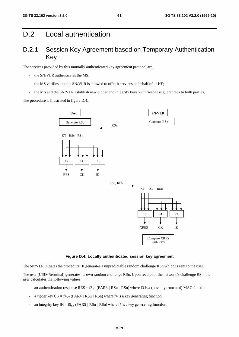
3GPP
3G TS 33.102 V3.2.0 (1999-10)613G TS 33.102 version 3.2.0
D.2 Local authentication
D.2.1 Session Key Agreement based on Temporary Authentication Key
The services provided by this mutually authenticated key agreement protocol are:
- the SN/VLR authenticates the MS;
- the MS verifies that the SN/VLR is allowed to offer it services on behalf of its HE;
- the MS and the SN/VLR establish new cipher and integrity keys with freshness guarantees to both parties.
The procedure is illustrated in figure D.4.
User
RSn
RSu, RES
Generate RSn
Compare XRESwith RES
SN/VLR
Generate RSu
RES CK IK
f3
KT RSu
f4
RSn
f5
XRES CK IK
f3
KT RSu
f4
RSn
f5
Figure D.4: Locally authenticated session key agreement
The SN/VLR initiates the procedure. It generates a unpredictable random challenge RSn which is sent to the user.
The user (USIM/terminal) generates its own random challenge RSu. Upon receipt of the network’s challenge RSn, the user calculates the following values:
- an authentication response RES = f3KT (PAR3 || RSu || RSn) where f3 is a (possibly truncated) MAC function.
- a cipher key CK = f4KT (PAR4 || RSu || RSn) where f4 is a key generating function.
- an integrity key IK = f5KT (PAR5 || RSu || RSn) where f5 is a key generating function.
3GPP
3G TS 33.102 V3.2.0 (1999-10)623G TS 33.102 version 3.2.0
Note 1: (See notes 1-5 in Clause D.1.2)
The USIM/terminal sends the network the random challenge RSu and the authentication response RES, and distributes the session keys CK and IK to the appropriate entities for ciphering and integrity.
Upon receipt of RSu and RES the SN/VLR computes XRES = f3KT (PAR3 || RSu || RSn) from RSu, RSn, and the temporary authentication key KT that is stored in the VLR database, and compares this with the value of RES received from the user. If they are unequal, the network sends a message back indicating that authentication has failed and abandons the authentication protocol. If the equality holds, the user is authenticated to the network.
The SN/VLR then computes the ciphering key CK = f4KT (PAR4 || RSu || RSn) and the integrity key IK = f5KT (PAR5 || RSu || RSn), which it distributes to the appropriate entities for ciphering and integrity.
D.3 Criteria for replacing the authentication “working assumption”
One of the following conditions should be met before considering replacement of the authentication “working assumption”:
- A serious security flaw is discovered with the SQN protocol. A “serious flaw” is a weakness that allows a demonstrable attack on the authentication system, leading to theft of service (fraud), compromise of privacy, or any degradation below the security level of current systems. If the flaw can be easily fixed without changing the fundamental nature of the protocol, there are no grounds for replacement.
- Serious operational difficulties are discovered with the SQN protocol. These are problems implementing the protocol that may be discovered during early development or testing. A “serious operation difficulty” is one that prevents the successful and reliable completion of the protocol. If the problem can be solved with a simple alteration that does not change the fundamental nature of the protocol, there are no grounds for replacement.

3GPP
3G TS 33.102 V3.2.0 (1999-10)633G TS 33.102 version 3.2.0
Annex E: A Proposal for Layer II Message Format
E.1 Introduction
In Layer II symmetric session keys (to encrypt/decrypt data before sending/after receiving) are distributed by the KACs in each network to the relevant network elements. For example, an AuCX will normally send sensitive authentication data to VLRY and will therefore get a session KSXY key from its KACX. Layer II is carried out entirely inside one operator's network.
However, in order to achieve a more consistent overall scheme, in this annex it is suggested to use for Layer II the same mechanism for distributing the keys as in Layer I. This requires the KACs of the different networks to generate and distribute asymmetric key pairs for the network elements of that network. These key-pairs will then be used to transfer the symmetric session keys in the same way as in Layer I.
The public and private key pairs needed for the network entities should be distributed to the entities in a secure way, which is in principle an operation & maintenance task. One way to do this is to distribute the key pairs, along with the necessary crypto-software, to the network entities in the form of chipcards, which can also carry out the necessary computations. Therefore, all that has to be added to the present network entities are chipcard readers with a standardised interface. Thus, on adoption of this proposal, in addition to their present tasks, the network entities would have to:
• Store the symmetric session keys to encrypt/decrypt data before sending/after receiving to/from network entities of other networks (external) and of their own network (internal)
• Encrypt/decrypt MAP messages according to their Mode of protection (cf. 7.4). The necessary computations may be carried out by a chipcard.
In addition to their tasks listed in 7.2.1 of the main document, the KACs would have to:
• Generate and store asymmetric key pairs for network entities in the same network
• Distribute asymmetric key pairs to network entities in the same network.
E.2 Proposed Layer II Message Format
The Layer II messages themselves take the same form as in 7.2 of the main document, where the 'receiving network Y' has to be replaced by 'receiving network entity NEX' (or X by NEY). Further, the Key Distribution Complete message is not needed in Layer II. However, the distribution of the session keys KSXY in network X having initiated the Layer I message exchange should not begin before the Key Distribution Complete Message from the receiving network Y has been received by the KACX in Layer I. As soon as a network element of X has received a session key KSXY, it may start enciphering with this key. A similar statement holds if the transported keys are used internally only: In this case, all network elements of X should get the symmetric session key KSXX to be used internal for encryption (marked as decryption key with flag RECEIVE) first; if all network elements have acknowledged that they have recovered these keys, the KACX sends the same key again (marked as encryption key with flag SEND). Again, as soon as a network element has received the session key KSXX (with flag SEND), it may start enciphering with this key.
[Note: As for layer I, no assumptions about the transport protocol are made, although IP might be a good candidate.]

3GPP
3G TS 33.102 V3.2.0 (1999-10)643G TS 33.102 version 3.2.0
E.2.1 Sending a session key for decryption
In order to transport a symmetric session key (marked with flag RECEIVE) with version no. i to be used to decrypt received data from network elements of network X in NEY, the KAC of Y sends a message containing the following data to NEY:
EPK(NEY) {X||NEY||RECEIVE||i||KSXY(i)||RNDY||Text1||DSK(Y)(Hash(X||NEY||RECEIVE||i||KSXY(i)||RNDY||Text1))||Text2}||
Text3
After having successfully decrypted the key transport message and having verified the digital signature of the sending network including the hash value, the receiving network entity sends an key installed message to its Key Administration Centre KACY. The message takes the form
KEY_INSTALLED||X||NEY||RNDY||i
This message can only be sent by the receiving network entity, because only this entity can know about RNDY. If anything goes wrong, e.g. computing the Hash of X||NEY||RECEIVE||i||KSXY(i)||RNDY||Text1 does not yield the expected result, a RESEND message should be sent by NEY to KACY in the form
RESEND||NEY
E.2.2 Sending a session key for encryption
In order to transport a symmetric SEND key with version no. i to be used for sending data from NEX to network elements of network Y, KACX sends a message containing the following data to NEX:
EPK(NEX) {NEX||Y||SEND||i||KSXY(i)||RNDX||Text1||DSK(X)(Hash(NEX||Y||SEND||i||KSXY(i)||RNDX||Text1))||Text2}||Text3

3GPP
3G TS 33.102 V3.2.0 (1999-10)653G TS 33.102 version 3.2.0
Annex F (Informative): Example uses of AMF
F.1 Support multiple authentication algorithms and keys
A mechanism to support the use of multiple authentication and key agreement algorithms is useful for disaster recovery purposes. AMF may be used to indicate the algorithm and key used to generate a particular authentication vector.
The USIM keeps track of the authentication algorithm and key identifier and updates it according to the received value.
F.2 Changing the size of windows and lists
This mechanisms is used in conjunction with the window and list mechanisms described in Annexes C.3 and C.4.
A mechanism to change the window and list size dynamically is useful since the optimum window and list size may change over time. AMF is used to indicate the maximum admissible window or list size to be used by the user when verifying the authentication token.
The USIM keeps track of the window or list size and updates it according to the received value providing that SQN > SQNMS.
F.3 Handling authentication vectors from separate CS/PS domains using a MODE parameter
A mechanism to distinguish authentication vectors from different CS/PS domains is useful so that separate CS/PS nodes can simultaneously and independently support mobility management for the user. AMF is used to indicate the domain associated with a particular authentication vector. Using this mechanism two counters are required for each domain in both the USIM and the AuC.
Note: If a single counter was used, the following problem occurs: Suppose that a CS node orders SQNs 1–5, and uses SQN 1 and then a PS node orders SQNs 6–10 and uses 6. At this point the CS node may need to use SQN 2, but cannot since the SQN will be rejected and must order new authentication vectors, with SQNs 11–15, and authenticates with SQN 11. Maintaining separate counters for CS and PS domains provide a solution for this problem.
An alternative to the use of the MODE parameter is the use of the window or list mechanism described in Annexes C3. and C.4.
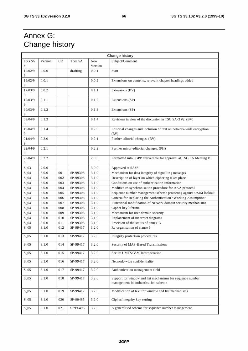
3GPP
3G TS 33.102 V3.2.0 (1999-10)663G TS 33.102 version 3.2.0
Annex G: Change history
Change history
TSG SA#
Version CR Tdoc SA New Version
Subject/Comment
10/02/99
0.0.0 drafting 0.0.1 Start
19/02/99
0.0.1 0.0.2 Extensions on contents, relevant chapter headings added
17/03/99
0.0.2 0.1.1 Extensions (BV)
19/03/99
0.1.1 0.1.2 Extensions (SP)
30/03/99
0.1.2 0.1.3 Extensions (SP)
09/04/99
0.1.3 0.1.4 Revisions in view of the discussion in TSG SA-3 #2. (BV)
19/04/99
0.1.4 0.2.0 Editorial changes and inclusion of text on network-wide encryption. (BV)
21/04/99
0.2.0 0.2.1 Further editorial changes. (BV)
22/04/99
0.2.1 0.2.2 Further minor editorial changes. (PH)
23/04/99
0.2.2 2.0.0 Formatted into 3GPP deliverable for approval at TSG SA Meeting #3
S_03 2.0.0 3.0.0 Approved at SA#3
S_04 3.0.0 001 SP-99308 3.1.0 Mechanism for data integrity of signalling messages
S_04 3.0.0 002 SP-99308 3.1.0 Description of layer on which ciphering takes place
S_04 3.0.0 003 SP-99308 3.1.0 Conditions on use of authentication information
S_04 3.0.0 004 SP-99308 3.1.0 Modified re-synchronisation procedure for AKA protocol
S_04 3.0.0 005 SP-99308 3.1.0 Sequence number management scheme protecting against USIM lockout
S_04 3.0.0 006 SP-99308 3.1.0 Criteria for Replacing the Authentication “Working Assumption”
S_04 3.0.0 007 SP-99308 3.1.0 Functional modification of Network domain security mechanisms
S_04 3.0.0 008 SP-99308 3.1.0 Cipher key lifetime
S_04 3.0.0 009 SP-99308 3.1.0 Mechanism for user domain security
S_04 3.0.0 010 SP-99308 3.1.0 Replacement of incorrect diagrams
S_04 3.0.0 011 SP-99308 3.1.0 Precision of the status of annex B S_05 3.1.0 012 SP-99417 3.2.0 Re-organisation of clause 6
S_05 3.1.0 013 SP-99417 3.2.0 Integrity protection procedures
S_05 3.1.0 014 SP-99417 3.2.0 Security of MAP-Based Transmissions
S_05 3.1.0 015 SP-99417 3.2.0 Secure UMTS-GSM Interoperation
S_05 3.1.0 016 SP-99417 3.2.0 Network-wide confidentiality
S_05 3.1.0 017 SP-99417 3.2.0 Authentication management field
S_05 3.1.0 018 SP-99417 3.2.0 Support for window and list mechanisms for sequence number management in authenticat ion scheme
S_05 3.1.0 019 SP-99417 3.2.0 Modification of text for window and list mechanisms
S_05 3.1.0 020 SP-99485 3.2.0 Cipher/integrity key setting
S_05 3.1.0 021 SP99-496 3.2.0 A generalised scheme for sequence number management

3GPP
3G TS 33.102 V3.2.0 (1999-10)673G TS 33.102 version 3.2.0
History
Document history
V3.0.0 May 1999 Approved at SA #3. Under TSG SA Change Control.
V3.1.0 July 1999 Including CRs approved at SA#4


![Netex learningMaker | What's New v3.2 [ES]](https://img.pdfslide.tips/doc/110x75/557c155dd8b42ae7748b5311/netex-learningmaker-whats-new-v32-es.jpg)