Embed Size (px)
Citation preview

3GPP TS 23.060 V7.4.0 (2007-03)Technical Specification
3rd Generation Partnership Project;Technical Specification Group Services and System Aspects;
General Packet Radio Service (GPRS);Service description;
Stage 2(Release 7)
GLOBAL SYSTEM FOR MOBILE COMMUNICATIONS
R
The present document has been developed within the 3rd Generation Partnership Project (3GPP TM) and may be further elaborated for the purposes of 3GPP. The present document has not been subject to any approval process by the 3GPP Organizational Partners and shall not be implemented. This Specification is provided for future development work within 3GPP only. The Organizational Partners accept no liability for any use of this Specification.Specifications and reports for implementation of the 3GPP TM system should be obtained via the 3GPP Organizational Partners' Publications Offices.

Release 7T 2 3GPP TS 23.060 V7.4.0 (2007-03)
Keywords GSM, GPRS, UMTS, Packet mode
3GPP
Postal address
3GPP support office address 650 Route des Lucioles - Sophia Antipolis
Valbonne - FRANCE Tel.: +33 4 92 94 42 00 Fax: +33 4 93 65 47 16
Internet http://www.3gpp.org
Copyright Notification
No part may be reproduced except as authorized by written permission. The copyright and the foregoing restriction extend to reproduction in all media.
© 2007, 3GPP Organizational Partners (ARIB, ATIS, CCSA, ETSI, TTA, TTC).
All rights reserved.
3GPP

Release 7T 3 3GPP TS 23.060 V7.4.0 (2007-03)
Contents Foreword ..........................................................................................................................................................10 1 Scope ......................................................................................................................................................11 2 References ..............................................................................................................................................11 3 Definitions, abbreviations and symbols .................................................................................................14 3.1 Definitions ....................................................................................................................................................... 14 3.2 Abbreviations................................................................................................................................................... 15 3.3 Symbols ........................................................................................................................................................... 17 4 Main Concept .........................................................................................................................................17 5 General GPRS Architecture and Transmission Mechanism ..................................................................18 5.1 GPRS Access Interfaces and Reference Points................................................................................................ 18 5.2 Network Interworking...................................................................................................................................... 19 5.2.1 Internet (IP) Interworking .......................................................................................................................... 19 5.3 High-Level Functions ...................................................................................................................................... 19 5.3.1 Network Access Control Functions............................................................................................................ 20 5.3.1.1 Registration Function ........................................................................................................................... 20 5.3.1.2 Authentication and Authorisation Function.......................................................................................... 20 5.3.1.3 Admission Control Function ................................................................................................................ 20 5.3.1.4 Message Screening Function ................................................................................................................ 20 5.3.1.5 Packet Terminal Adaptation Function .................................................................................................. 20 5.3.1.6 Charging Data Collection Function ...................................................................................................... 20 5.3.1.7 Operator Determined Barring Function................................................................................................ 20 5.3.2 Packet Routeing and Transfer Functions.................................................................................................... 21 5.3.2.1 Relay Function...................................................................................................................................... 21 5.3.2.2 Routeing Function ................................................................................................................................ 21 5.3.2.3 Address Translation and Mapping Function......................................................................................... 21 5.3.2.4 Encapsulation Function ........................................................................................................................ 21 5.3.2.5 Tunnelling Function ............................................................................................................................. 21 5.3.2.6 Compression Function.......................................................................................................................... 21 5.3.2.7 Ciphering Function............................................................................................................................... 21 5.3.2.8 Domain Name Server Function ............................................................................................................ 21 5.3.3 Mobility Management Functions ............................................................................................................... 22 5.3.4 Logical Link Management Functions (A/Gb mode) .................................................................................. 22 5.3.4.1 Logical Link Establishment Function................................................................................................... 22 5.3.4.2 Logical Link Maintenance Functions ................................................................................................... 22 5.3.4.3 Logical Link Release Function............................................................................................................. 22 5.3.5 Radio Resource Management Functions .................................................................................................... 22 5.3.6 Network Management Functions ............................................................................................................... 22 5.4 Logical Architecture ........................................................................................................................................ 22 5.4.1 GPRS Core Network Nodes....................................................................................................................... 23 5.4.2 GPRS Packet Domain PLMN Backbone Networks ................................................................................... 24 5.4.3 HLR............................................................................................................................................................ 24 5.4.4 SMS-GMSC and SMS-IWMSC................................................................................................................. 24 5.4.5 Mobile Stations (A/Gb mode) .................................................................................................................... 25 5.4.6 Mobile Stations (Iu mode).......................................................................................................................... 25 5.4.7 Charging Gateway Functionality................................................................................................................ 25 5.5 Assignment of Functions to General Logical Architecture.............................................................................. 26 5.6 User and Control Planes .................................................................................................................................. 27 5.6.1 User Plane (A/Gb mode) ............................................................................................................................ 27 5.6.1.1 MS – GGSN ......................................................................................................................................... 27 5.6.1.2 GSN – GSN .......................................................................................................................................... 28 5.6.2 User Plane (Iu mode) ................................................................................................................................. 28 5.6.2.1 MS – GGSN user plane with GERAN in Iu mode ............................................................................... 28 5.6.2.2 MS – GGSN user plane with UTRAN ................................................................................................. 28 5.6.2.3 GSN – GSN .......................................................................................................................................... 29
3GPP

Release 7T 4 3GPP TS 23.060 V7.4.0 (2007-03)
5.6.3 Control Plane.............................................................................................................................................. 29 5.6.3.1 MS – SGSN (A/Gb mode).................................................................................................................... 30 5.6.3.2 MS – SGSN (Iu mode) ......................................................................................................................... 30 5.6.3.3 SGSN - HLR......................................................................................................................................... 31 5.6.3.4 SGSN - MSC/VLR............................................................................................................................... 31 5.6.3.5 SGSN - EIR .......................................................................................................................................... 31 5.6.3.6 SGSN - SMS-GMSC or SMS-IWMSC................................................................................................ 32 5.6.3.7 GSN - GSN........................................................................................................................................... 32 5.6.3.8 GGSN - HLR........................................................................................................................................ 32 5.6.3.8.1 MAP-based GGSN - HLR Signalling ............................................................................................. 32 5.6.3.8.2 GTP and MAP-based GGSN - HLR Signalling.............................................................................. 33 5.7 Functionality Needed for Mobile IP Using IPv4 ............................................................................................. 33 5.8 Functionality for Intra Domain Connection of RAN Nodes to Multiple CN Nodes........................................ 33 5.9 Functionality for network sharing.................................................................................................................... 34 6 Mobility Management Functionality......................................................................................................34 6.1 Definition of Mobility Management States ..................................................................................................... 34 6.1.1 Mobility Management States (A/Gb mode) ............................................................................................... 34 6.1.1.1 IDLE (GPRS) State .............................................................................................................................. 34 6.1.1.2 STANDBY State .................................................................................................................................. 34 6.1.1.3 READY State ....................................................................................................................................... 35 6.1.1.4 State Transitions and Functions............................................................................................................ 36 6.1.2 Mobility Management States (Iu mode)..................................................................................................... 37 6.1.2.1 PMM-DETACHED State ..................................................................................................................... 37 6.1.2.2 PMM-IDLE State ................................................................................................................................. 37 6.1.2.3 PMM-CONNECTED State .................................................................................................................. 37 6.1.2.4 State Transitions and Functions............................................................................................................ 38 6.1.2.4.1 Handling of Un-synchronous States in the UE and the Network.................................................... 39 6.2 Mobility Management Timer Functions .......................................................................................................... 40 6.2.1 READY Timer Function (A/Gb mode)...................................................................................................... 40 6.2.2 Periodic RA Update Timer Function.......................................................................................................... 40 6.2.3 Mobile Reachable Timer Function............................................................................................................. 41 6.3 Interactions Between SGSN and MSC/VLR ................................................................................................... 41 6.3.1 Administration of the SGSN - MSC/VLR Association.............................................................................. 42 6.3.2 Combined RA / LA Updating .................................................................................................................... 43 6.3.3 CS Paging (A/Gb mode) ............................................................................................................................ 43 6.3.3.1 Paging Co-ordination in A/Gb mode.................................................................................................... 44 6.3.4 CS Paging (Iu mode) .................................................................................................................................. 45 6.3.4.1 Network Operation Modes for Iu mode................................................................................................ 45 6.3.4a CS Paging (in case Selective RA Update).................................................................................................. 46 6.3.5 Non-GPRS Alert ........................................................................................................................................ 46 6.3.6 MS Information Procedure......................................................................................................................... 46 6.3.7 MM Information Procedure ....................................................................................................................... 47 6.4 MM Procedures ............................................................................................................................................... 47 6.5 GPRS Attach Function..................................................................................................................................... 48 6.5.1 A/Gb mode GPRS Attach Procedure ......................................................................................................... 48 6.5.2 Iu mode GPRS Attach Procedure............................................................................................................... 49 6.5.3 Combined GPRS / IMSI Attach procedure ................................................................................................ 50 6.6 Detach Function............................................................................................................................................... 53 6.6.1 MS-Initiated Detach Procedure .................................................................................................................. 54 6.6.2 Network-Initiated Detach Procedure.......................................................................................................... 55 6.6.2.1 SGSN-Initiated Detach Procedure........................................................................................................ 55 6.6.2.2 HLR-Initiated Detach Procedure .......................................................................................................... 56 6.7 Purge Function................................................................................................................................................. 57 6.8 Security Function............................................................................................................................................. 57 6.8.1 Authentication ............................................................................................................................................ 57 6.8.1.1 GSM Authentication procedure............................................................................................................ 57 6.8.1.2 UMTS Authentication procedure ......................................................................................................... 58 6.8.2 User Identity Confidentiality...................................................................................................................... 59 6.8.2.1 User Identity Confidentiality (A/Gb mode).......................................................................................... 59 6.8.2.2 User Identity Confidentiality (Iu mode) ............................................................................................... 59 6.8.2.3 P-TMSI Signature................................................................................................................................. 60
3GPP

Release 7T 5 3GPP TS 23.060 V7.4.0 (2007-03)
6.8.2.4 P-TMSI Reallocation Procedure........................................................................................................... 60 6.8.3 User Data and GMM/SM Signalling Confidentiality................................................................................. 60 6.8.3.1 Scope of Ciphering ............................................................................................................................... 60 6.8.3.2 Ciphering Algorithm............................................................................................................................. 61 6.8.3.3 Start of Ciphering ................................................................................................................................. 61 6.8.4 Identity Check Procedures ......................................................................................................................... 61 6.8.5 Data Integrity Procedure (Iu mode)............................................................................................................ 61 6.9 Location Management Function ...................................................................................................................... 61 6.9.1 Location Management Procedures (A/Gb mode)....................................................................................... 62 6.9.1.1 Cell Update Procedure.......................................................................................................................... 62 6.9.1.2 Routeing Area Update Procedure ......................................................................................................... 63 6.9.1.2.1 Intra SGSN Routeing Area Update ................................................................................................. 63 6.9.1.2.2 Inter SGSN Routeing Area Update ................................................................................................. 64 6.9.1.3 Combined RA / LA Update Procedure ................................................................................................. 67 6.9.1.3.1 Combined Intra SGSN RA / LA Update......................................................................................... 67 6.9.1.3.2 Combined Inter SGSN RA / LA Update......................................................................................... 69 6.9.2 Location Management Procedures (Iu-mode) ............................................................................................ 72 6.9.2.1 Routeing Area Update Procedure ......................................................................................................... 73 6.9.2.2 Serving RNS Relocation Procedures .................................................................................................... 78 6.9.2.2.1 Serving RNS Relocation Procedure ................................................................................................ 79 6.9.2.2.2 Combined Hard Handover and SRNS Relocation Procedure ......................................................... 85 6.9.2.2.3 Combined Cell / URA Update and SRNS Relocation Procedure ................................................... 91 6.9.2.2.4 SRNS Relocation Cancel Procedure ............................................................................................... 96 6.9.3 Periodic RA and LA Updates..................................................................................................................... 97 6.9.4 PS Handover Procedure ............................................................................................................................. 97 6.10 Tunnelling of non-GSM Signalling Messages Function (A/Gb mode)............................................................ 98 6.10.1 Uplink Tunnelling of non-GSM Signalling Messages Procedure .............................................................. 98 6.10.2 Downlink Tunnelling of non-GSM Signalling Messages Procedure ......................................................... 99 6.11 Subscriber Management Function ................................................................................................................... 99 6.11.1 Subscriber Management Procedures .......................................................................................................... 99 6.11.1.1 Insert Subscriber Data Procedure ......................................................................................................... 99 6.11.1.2 Delete Subscriber Data Procedure ...................................................................................................... 100 6.12 Service Request Procedure (Iu mode)............................................................................................................ 100 6.12.1 MS Initiated Service Request Procedure.................................................................................................. 101 6.12.2 Network Initiated Service Request Procedure.......................................................................................... 102 6.13 Intersystem Change........................................................................................................................................ 104 6.13.1 Intra SGSN Intersystem Change .............................................................................................................. 104 6.13.1.1 Iu mode to A/Gb mode Intra SGSN Change ...................................................................................... 104 6.13.1.2 A/Gb mode to Iu mode Intra-SGSN Change ...................................................................................... 107 6.13.1.3 Selective RA Update .......................................................................................................................... 110 6.13.1.3.1 Uplink Signalling or Data Transmission....................................................................................... 110 6.13.1.3.2 Downlink Signalling or Data Transmission .................................................................................. 110 6.13.2 Inter-SGSN Inter-system Change............................................................................................................. 111 6.13.2.1 Iu mode to A/Gb mode Inter-SGSN Change ...................................................................................... 111 6.13.2.2 A/Gb mode to Iu mode Inter-SGSN Change ...................................................................................... 116 6.14 Classmark Handling....................................................................................................................................... 121 6.14.1 Radio Access Classmark .......................................................................................................................... 121 6.14.1.1 MS Radio Access Capability (A/Gb mode)........................................................................................ 121 6.14.1.2 UE Capability (Iu mode) .................................................................................................................... 121 6.14.2 MS Network Capability ........................................................................................................................... 122 7 Network Management Functionality....................................................................................................122 8 Radio Resource Functionality ..............................................................................................................122 8.1 Radio Resource Functionality (A/Gb mode).................................................................................................. 122 8.1.1 Cell Selection and Reselection ................................................................................................................. 122 8.1.2 Discontinuous Reception.......................................................................................................................... 122 8.1.3 Radio Resource Management................................................................................................................... 122 8.1.3.1 Layer Functions .................................................................................................................................. 123 8.1.3.2 Model of Operation ............................................................................................................................ 123 8.1.3.2.1 Dynamic Allocation of Radio Resources...................................................................................... 123 8.1.4 Paging for GPRS Downlink Transfer....................................................................................................... 123
3GPP

Release 7T 6 3GPP TS 23.060 V7.4.0 (2007-03)
8.1.5 RAN Information Management (RIM) procedures .................................................................................. 124 8.1.5.1 General ............................................................................................................................................... 124 8.1.5.2 Addressing, routeing and relaying...................................................................................................... 124 8.1.5.2.1 Addressing .................................................................................................................................... 124 8.1.5.2.2 Routeing........................................................................................................................................ 124 8.1.5.2.3 Relaying ........................................................................................................................................ 125 8.1.5.3 Void .................................................................................................................................................... 125 8.1.5.4 Void .................................................................................................................................................... 125 8.1.5.5 Applications using the RIM Procedures ............................................................................................. 125 8.1.6 BSS Paging Co-ordination ....................................................................................................................... 125 8.2 Radio Resource Functionality (Iu mode) ....................................................................................................... 125 8.2.1 Radio Resource Management................................................................................................................... 125 8.2.2 RRC State Machine.................................................................................................................................. 126 8.2.3 Discontinuous Reception.......................................................................................................................... 126 8.2.4 Paging Initiated by CN............................................................................................................................. 126 8.2.4.1 PS Paging Initiated by 3G-SGSN without RRC Connection for CS .................................................. 127 8.2.4.2 PS Paging Initiated by 3G-SGSN With RRC Connection for CS ...................................................... 128 8.2.5 Paging Initiated by RAN.......................................................................................................................... 128 9 Packet Routeing and Transfer Functionality ........................................................................................129 9.1 Definition of Packet Data Protocol States...................................................................................................... 129 9.1.1 INACTIVE State...................................................................................................................................... 129 9.1.2 ACTIVE State .......................................................................................................................................... 130 9.2 PDP Context Activation, Modification, Deactivation, and Preservation Functions ...................................... 130 9.2.1 Static and Dynamic PDP Addresses......................................................................................................... 132 9.2.1.1 Dynamic IPv6 Address Allocation ..................................................................................................... 132 9.2.2 Activation Procedures .............................................................................................................................. 134 9.2.2.1 PDP Context Activation Procedure .................................................................................................... 134 9.2.2.1.1 Secondary PDP Context Activation Procedure............................................................................. 137 9.2.2.2 Network-Requested PDP Context Activation Procedure.................................................................... 140 9.2.2.2.1 Successful Network-Requested PDP Context Activation Procedure............................................ 141 9.2.2.2.2 Unsuccessful Network-Requested PDP Context Activation Procedure........................................ 141 9.2.2.3 Network Requested Secondary PDP Context Activation Procedure .................................................. 143 9.2.3 Modification Procedures .......................................................................................................................... 144 9.2.3.1 SGSN-Initiated PDP Context Modification Procedure....................................................................... 145 9.2.3.2 GGSN-Initiated PDP Context Modification Procedure...................................................................... 146 9.2.3.3 MS-Initiated PDP Context Modification Procedure ........................................................................... 148 9.2.3.4 RNC/BSS-Initiated PDP Context Modification Procedure ................................................................ 150 9.2.3.5 RAB Release-Initiated Local PDP Context Modification Procedure ................................................. 151 9.2.3.6 RAN-initiated RAB Modification Procedure (Iu mode)..................................................................... 151 9.2.4 Deactivation Procedures........................................................................................................................... 152 9.2.4.1 MS Initiated PDP Context Deactivation Procedure............................................................................ 152 9.2.4.2 SGSN-initiated PDP Context Deactivation Procedure ....................................................................... 153 9.2.4.3 GGSN-initiated PDP Context Deactivation Procedure....................................................................... 154 9.2.5 Preservation Procedures ........................................................................................................................... 154 9.2.5.1 Release of RABs Triggered by an Iu mode RAN............................................................................... 155 9.2.5.1.1 RAB Release Procedure................................................................................................................ 155 9.2.5.1.2 Iu Release Procedure..................................................................................................................... 155 9.2.5.2 Re-establishment of RABs ................................................................................................................. 155 9.3 Packet Routeing and Transfer Function......................................................................................................... 155 9.4 Relay Function............................................................................................................................................... 156 9.5 Packet Terminal Adaptation Function ........................................................................................................... 157 9.6 Encapsulation Function.................................................................................................................................. 157 9.6.1 Encapsulation Between GSNs.................................................................................................................. 157 9.6.2 Encapsulation Between SGSN and RAN in Iu mode............................................................................... 157 9.6.3 Encapsulation Between SGSN and MS in A/Gb mode............................................................................ 157 9.6.4 Encapsulation Between RAN and MS in Iu mode ................................................................................... 157 10 Message Screening Functionality.........................................................................................................157 11 Compatibility Issues.............................................................................................................................158 11.1 Interaction between Releases 97/98 and 99 ................................................................................................... 158 11.1.1 Interactions Between GTP v0 (R97) and GTP v1 (R99).......................................................................... 158
3GPP

Release 7T 7 3GPP TS 23.060 V7.4.0 (2007-03)
11.1.2 Interactions Between MS R97 and CN R99............................................................................................. 159 11.1.3 Interactions Between SM R97 and SM R99............................................................................................. 159 11.1.4 Interactions Between MAP R97 and MAP R99....................................................................................... 159 12 Transmission ........................................................................................................................................159 12.1 Transmission Modes ...................................................................................................................................... 159 12.1.1 GTP-U Transmission Modes.................................................................................................................... 159 12.1.2 LLC Transmission Modes (A/Gb mode).................................................................................................. 159 12.1.3 RLC Transmission Modes........................................................................................................................ 160 12.2 Logical Link Control Functionality (A/Gb mode) ......................................................................................... 160 12.2.1 Addressing ............................................................................................................................................... 160 12.2.2 Services .................................................................................................................................................... 160 12.2.3 Functions.................................................................................................................................................. 160 12.3 Subnetwork Dependent Convergence Functionality (A/Gb mode) ............................................................... 161 12.3.1 Services .................................................................................................................................................... 161 12.3.2 Subfunctions............................................................................................................................................. 162 12.4 PDCP (Iu mode) ............................................................................................................................................ 162 12.5 Point-to-Point Protocol Functionality ............................................................................................................ 162 12.5.1 User Plane for PDP Type PPP.................................................................................................................. 162 12.5.2 Functions.................................................................................................................................................. 163 12.6 Gb Interface (A/Gb mode) ............................................................................................................................. 163 12.6.1 Physical Layer Protocol ........................................................................................................................... 164 12.6.2 Link Layer Protocols................................................................................................................................ 164 12.6.3 BSS GPRS Protocol ................................................................................................................................. 164 12.6.3.1 Inter-dependency of the BSSGP and LLC Functions ......................................................................... 164 12.6.3.2 BSSGP Addressing............................................................................................................................. 165 12.6.3.3 BVCI Contexts in BSS and in SGSN ................................................................................................. 165 12.6.3.4 Flow Control Between SGSN and BSS over the Gb Interface ........................................................... 165 12.6.3.5 BSS Context ....................................................................................................................................... 166 12.6.3.5.1 BSS Packet Flow Context Creation Procedure ............................................................................. 167 12.6.3.5.2 SGSN-Initiated BSS Packet Flow Context Modification Procedure ............................................ 167 12.6.3.5.3 BSS-Initiated BSS Packet Flow Context Modification Procedure................................................ 168 12.6.3.5.4 BSS Packet Flow Context Deletion Procedures............................................................................ 168 12.7 Iu Interface (Iu mode) .................................................................................................................................... 169 12.7.1 Consistent Sequence Numbering of PDUs on Iu and Gn Interfaces ........................................................ 169 12.7.2 [void]........................................................................................................................................................ 169 12.7.2a RAB Release Procedure ........................................................................................................................... 169 12.7.3 Iu Release Procedure................................................................................................................................ 170 12.7.4 RAB Assignment Procedure .................................................................................................................... 171 12.7.5 Location Reporting Procedure ................................................................................................................. 172 12.8 Abis Interface (A/Gb mode) .......................................................................................................................... 172 12.8.1 Remote Packet Control Unit .................................................................................................................... 173 12.9 Gn Interface (A/Gb mode) ............................................................................................................................. 174 13 Information Storage..............................................................................................................................174 13.1 HLR ............................................................................................................................................................... 174 13.2 SGSN............................................................................................................................................................. 175 13.3 GGSN ............................................................................................................................................................ 178 13.4 MS ................................................................................................................................................................. 179 13.5 MSC/VLR...................................................................................................................................................... 180 13.6 BSS in A/Gb mode ........................................................................................................................................ 180 13.7 RNC/BSC for Iu mode................................................................................................................................... 180 13.8 Recovery and Restoration Procedures ........................................................................................................... 181 13.8.1 HLR Failure ............................................................................................................................................. 181 13.8.2 SGSN Failure ........................................................................................................................................... 181 13.8.3 GGSN Failure........................................................................................................................................... 182 13.8.4 VLR Failure ............................................................................................................................................. 182 13.8.5 BSS Failure (A/Gb mode) ........................................................................................................................ 183 13.8.6 RNC/BSC Failure (Iu mode).................................................................................................................... 183 14 Identities...............................................................................................................................................183 14.1 IMSI............................................................................................................................................................... 183 14.2 Packet TMSI .................................................................................................................................................. 183
3GPP
Release 7T 8 3GPP TS 23.060 V7.4.0 (2007-03)
14.3 NSAPI and TLLI for A/Gb mode .................................................................................................................. 183 14.4 NSAPI, RB Identity, and RAB ID for Iu mode ............................................................................................. 184 14.5 PDP Address.................................................................................................................................................. 185 14.6 TEID .............................................................................................................................................................. 185 14.7 Routeing Area Identity................................................................................................................................... 186 14.8 RAN Registration Area Identity (Iu mode).................................................................................................... 186 14.9 Cell Identity ................................................................................................................................................... 186 14.10 Service Area Identity (Iu mode) .................................................................................................................... 186 14.11 GSN Addresses .............................................................................................................................................. 186 14.11.1 GSN Address............................................................................................................................................ 186 14.11.2 GSN Number............................................................................................................................................ 187 14.12 RNC/BSC Addresses (Iu mode) .................................................................................................................... 187 14.12.1 RNC/BSC Address................................................................................................................................... 187 14.12.2 RNC/BSC Number................................................................................................................................... 187 14.13 Access Point Name ........................................................................................................................................ 187 15 Operational Aspects .............................................................................................................................187 15.1 Charging ........................................................................................................................................................ 187 15.1.1 Charging Information............................................................................................................................... 188 15.1.1a General impacts of applying Flow Based Charging................................................................................. 188 15.1.2 Reverse Charging ..................................................................................................................................... 189 15.1.3 Location dependent charging ................................................................................................................... 189 15.1.3.1 Basic principles .................................................................................................................................. 189 15.1.3.2 Interaction with CGI / SAI reporting.................................................................................................. 190 15.2 Quality of Service Profile .............................................................................................................................. 190 15.2.1 Radio Priority Levels (A/Gb mode) ......................................................................................................... 191 15.3 Traffic Flow Template ................................................................................................................................... 191 15.3.1 Rules for Operations on TFTs.................................................................................................................. 191 15.3.2 Packet Filter Attributes............................................................................................................................. 192 15.3.2.1 Remote Address and Subnet Mask ..................................................................................................... 192 15.3.2.2 Protocol Number / Next Header ......................................................................................................... 193 15.3.2.3 Port Numbers...................................................................................................................................... 193 15.3.2.4 IPSec Security Parameter Index ......................................................................................................... 193 15.3.2.5 Type of Service / Traffic Class and Mask .......................................................................................... 193 15.3.2.6 Flow Label.......................................................................................................................................... 193 15.3.3 Example Usage of Packet Filters.............................................................................................................. 193 15.3.3.1 IPv4 Multi-field Classification ........................................................................................................... 193 15.3.3.2 IPv4 TOS-based Classification........................................................................................................... 193 15.3.3.3 IPv4 Multi-field Classification for IPSec Traffic ............................................................................... 194 15.4 APN Restriction............................................................................................................................................. 194 15.5 Automatic Device Detection.......................................................................................................................... 195 15.6 Direct Tunnel Functionality........................................................................................................................... 195 16 Interactions with Other Services ..........................................................................................................196 16.1 Point-to-point Short Message Service............................................................................................................ 196 16.1.1 Mobile-terminated SMS Transfer....................................................................................................... 196 16.1.1.1 Unsuccessful Mobile-terminated SMS Transfer ........................................................................... 197 16.1.2 Mobile-originated SMS Transfer........................................................................................................ 200 16.2 Circuit-switched Services (A/Gb mode) ........................................................................................................ 201 16.2.1 Suspension of GPRS Services.................................................................................................................. 201 16.2.1.1 Suspend and Resume procedure (A/Gb mode)................................................................................... 201 16.2.1.1.1 Intra-SGSN Suspend and Resume procedure................................................................................ 201 16.2.1.1.2 Inter-SGSN Suspend and Resume procedure................................................................................ 202 16.2.1.2 Inter-System Suspend and Resume procedure.................................................................................... 203 16.2.1.2.1 Intra-SGSN Suspend and Resume procedure................................................................................ 203 16.2.1.2.2 Inter-SGSN Suspend and Resume procedure................................................................................ 204 16.2.1.3 Inter System Resume procedure ......................................................................................................... 205 16.2.1.3.1 Intra-SGSN Resume procedure..................................................................................................... 205 16.2.1.3.2 Inter-SGSN Resume procedure..................................................................................................... 205 16.2.2 GPRS and Dedicated Mode Priority Handling......................................................................................... 206 16.3 Supplementary Services................................................................................................................................. 206 16.4 CAMEL Services........................................................................................................................................... 206
3GPP

Release 7T 9 3GPP TS 23.060 V7.4.0 (2007-03)
Annex A (normative): APN and GGSN Selection ...........................................................................207 A.1 Definitions............................................................................................................................................207 A.2 Selection Rules.....................................................................................................................................207
Annex B (informative): Change History ............................................................................................215
3GPP

Release 7T 10 3GPP TS 23.060 V7.4.0 (2007-03)
Foreword This Technical Specification has been produced by the 3rd Generation Partnership Project (3GPP).
The contents of the present document are subject to continuing work within the TSG and may change following formal TSG approval. Should the TSG modify the contents of the present document, it will be re-released by the TSG with an identifying change of release date and an increase in version number as follows:
Version x.y.z
where:
x the first digit:
1 presented to TSG for information;
2 presented to TSG for approval;
3 or greater indicates TSG approved document under change control.
y the second digit is incremented for all changes of substance, i.e. technical enhancements, corrections, updates, etc.
z the third digit is incremented when editorial only changes have been incorporated in the document.
3GPP

Release 7T 11 3GPP TS 23.060 V7.4.0 (2007-03)
1 Scope The present document defines the stage-2 service description for the General Packet Radio Service (GPRS) which is a packet bearer service and a main part of the packet domain. ITU-T Recommendation I.130 [29] describes a three-stage method for characterisation of telecommunication services, and ITU-T Recommendation Q.65 [31] defines stage 2 of the method.
The present document does not cover the Radio Access Network functionality. TS 43.064 [11] contains an overall description of the GSM GPRS Access Network. TS 25.401 [53] contains an overall description of the UMTS Terrestrial Radio Access Network. TS 43.051 [74] contains an overall description of GSM/EDGE Radio Access Network.
2 References The following documents contain provisions, which, through reference in this text, constitute provisions of the present document.
• References are either specific (identified by date of publication, edition number, version number, etc.) or non-specific.
• For a specific reference, subsequent revisions do not apply.
• For a non-specific reference, the latest version applies. In the case of a reference to a 3GPP document (including a GSM document), a non-specific reference implicitly refers to the latest version of that document in the same Release as the present document.
[1] Void.
[2] 3GPP TS 41.061: "General Packet Radio Service (GPRS); GPRS ciphering algorithm requirements".
[3] 3GPP TS 22.060: "General Packet Radio Service (GPRS); Service description; Stage 1".
[4] 3GPP TS 23.003: "Numbering, addressing and identification".
[5] 3GPP TS 23.007: "Restoration procedures".
[5b] 3GPP TS 23.016: "Subscriber data management; Stage 2".
[6] 3GPP TS 43.020: "Security related network functions".
[7] GSM 03.22: "Digital cellular telecommunications system (Phase 2+); Functions related to Mobile Station (MS) in idle mode and group receive mode".
[7b] 3GPP TS 23.122: "Non-Access Stratum functions related to Mobile Station (MS) in idle mode".
[8] 3GPP TS 23.040: "Technical realization of the Short Message Service (SMS)".
[8b] 3GPP TS 23.078: "Customised Applications for Mobile network Enhanced Logic (CAMEL) Phase 3 - Stage 2".
[9] 3GPP TS 21.905: "Vocabulary for 3GPP Specifications", (Release 4).
[10] Void.
[11] 3GPP TS 43.064: "General Packet Radio Service (GPRS); Overall description of the GPRS radio interface; Stage 2".
[12] 3GPP TS 24.007: "Mobile radio interface signalling layer 3; General aspects".
[13] 3GPP TS 24.008: "Mobile Radio Interface Layer 3 specification; Core Network Protocols; Stage 3".
3GPP
Release 7T 12 3GPP TS 23.060 V7.4.0 (2007-03)
[13b] 3GPP TS 24.011: "Point to Point (PP) Short Message Service (SMS) support on mobile radio interface".
[14] Void.
[15] 3GPP TS 44.064: "General Packet Radio Service (GPRS); Mobile Station – Serving GPRS Support Node (MS-SGSN) Logical Link Control (LLC) layer specification".
[16] 3GPP TS 44.065: "General Packet Radio Service (GPRS); Mobile Station (MS) – Serving GPRS Support Node (SGSN); Subnetwork Dependent Convergence Protocol (SNDCP)".
[16b] 3GPP TS 45.008: "Digital cellular telecommunications system (Phase 2+); Radio subsystem link control".
[17] 3GPP TS 27.060: "Packet Domain; Mobile Station (MS) supporting Packet Switched services".
[18] 3GPP TS 48.008: "Mobile-services Switching Centre - Base Station System (MSC-BSS) interface; Layer 3 specification".
[19] 3GPP TS 48.014: "General Packet Radio Service (GPRS); Base Station System (BSS) - Serving GPRS Support Node (SGSN) interface; Gb interface layer 1".
[20] 3GPP TS 48.016: "General Packet Radio Service (GPRS); Base Station System (BSS) - Serving GPRS Support Node (SGSN) interface; Network Service".
[21] Void.
[22] 3GPP TS 48.060: "In-band control of remote transcoders and rate adaptors for Enhanced Full Rate (EFR) and full rate traffic channels".
[23] 3GPP TS 29.002: "Mobile Application Part (MAP) specification".
[24] 3GPP TS 29.016: "General Packet Radio Service (GPRS); Serving GPRS Support Node (SGSN) - Visitors Location Register (VLR); Gs interface network service specification".
[25] 3GPP TS 29.018: "General Packet Radio Service (GPRS); Serving GPRS Support Node (SGSN) - Visitors Location Register (VLR); Gs interface layer 3 specification".
[26] 3GPP TS 29.060: "General Packet Radio Service (GPRS); GPRS Tunnelling Protocol (GTP) across the Gn and Gp Interface".
[27] 3GPP TS 29.061: "Interworking between the Public Land Mobile Network (PLMN) supporting Packet Based services and Packet Data Networks (PDN)".
[27b] Void.
[28] 3GPP TS 51.011: "Specification of the Subscriber Identity Module - Mobile Equipment (SIM-ME) interface".
[29] ITU-T Recommendations I.130: "Method for the characterization of telecommunication services supported by an ISDN and network capabilities of an ISDN".
[30] ITU-T Recommendation E.164: "The international public telecommunication numbering plan".
[31] ITU-T Recommendation Q.65: "The unified functional methodology for the characterization of services and network capabilities".
[32] ITU-T Recommendation V.42bis: "Data compression procedures for data circuit-terminating equipment (DCE) using error correction procedures".
[33] Void.
[34] ITU-T Recommendation X.25: "Interface between Data Terminal Equipment (DTE) and Data Circuit-terminating Equipment (DCE) for terminals operating in the packet mode and connected to public data networks by dedicated circuit".
[39] RFC 768 (1980): "User Datagram Protocol" (STD 6).
3GPP

Release 7T 13 3GPP TS 23.060 V7.4.0 (2007-03)
[40] RFC 791 (1981): "Internet Protocol" (STD 5).
[41] RFC 792 (1981): "Internet Control Message Protocol" (STD 5).
[42] Void.
[43] RFC 1034 (1987): "Domain names – concepts and facilities" (STD 13).
[44] RFC 1661 (1994): "The Point-to-Point Protocol (PPP)" (STD 51).
[45] RFC 1542 (1993): "Clarifications and Extensions for the Bootstrap Protocol".
[46] RFC 3344 (2002): "IP Mobility Support".
[47] RFC 2131 (1997): "Dynamic Host Configuration Protocol".
[48] RFC 2460 (1998): "Internet Protocol, Version 6 (IPv6) Specification".
[49] TIA/EIA-136 (1999): "TDMA Cellular / PCS"; Arlington: Telecommunications Industry Association.
[50] 3GPP TS 25.301: "Radio Interface Protocol Architecture".
[51] 3GPP TS 25.303: "Interlayer procedures in Connected Mode".
[51b] 3GPP TS 25.304: "UE Procedures in Idle Mode and Procedures for Call Reselection in Connected Mode".
[52] 3GPP TS 25.331: "RRC Protocol Specification".
[53] 3GPP TS 25.401: "UTRAN Overall Description".
[54] 3GPP TS 23.121: "Architectural Requirements for Release 1999".
[55] 3GPP TS 25.322: "RLC protocol specification".
[56] 3GPP TS 25.412: "UTRAN Iu Interface Signalling Transport".
[56b] 3GPP TS 25.413: "UTRAN Iu Interface RANAP Signalling".
[57] 3GPP TS 25.323: "Packet Data Convergence Protocol (PDCP) specification".
[58] 3GPP TS 23.107: "Quality of Service (QoS) concept and architecture".
[59] ITU-T Recommendation I.361: "B-ISDN ATM layer specification".
[60] 3GPP TS 25.321: "Medium Access Control (MAC) protocol specification".
[61] 3GPP TS 33.102: "3G Security; Security architecture".
[62] Void.
[63] 3GPP TS 25.411: "UTRAN Iu interface Layer 1".
[64] 3GPP TS 25.414: "UTRAN Iu interface data transport & transport signalling".
[65] 3GPP TS 23.271: "Functional stage 2 description of LCS".
[66] 3GPP TS 23.015: "Technical realization of Operator Determined Barring (ODB)".
[67] ITU-T Recommendation I.363.5: "B-ISDN ATM Adaptation Layer (AAL) specification: Type 5 AAL".
[68] RFC 2373 (1998): "IP Version 6 Addressing Architecture".
[69] RFC 2462 (1998): "IPv6 Stateless Address Autoconfiguration".
[70] 3GPP TS 32.251: "Telecommunication management; Charging management; Packet Switched (PS) domain charging".
3GPP
Release 7T 14 3GPP TS 23.060 V7.4.0 (2007-03)
[71] RFC 2461 (1998): "Neighbor Discovery for IP Version 6 (IPv6)".
[72] 3GPP TS 29.202: "Signalling System No. 7 (SS7) signalling transport in core network; Stage 3".
[73] 3GPP TS 23.236: "Intra Domain Connection of RAN Nodes to Multiple CN Nodes".
[74] 3GPP TS 43.051: "Radio Access Network; Overall description – Stage 2".
[75] 3GPP TS 24.229: IP Multimedia Call Control Protocol based on SIP and SDP.
[76] 3GPP TS 23.195: "Provision of UE Specific Behaviour Information to Network Entities".
[77] 3GPP TS 44.060: General Packet Radio Service (GPRS); Mobile Station (MS) - Base Station System (BSS) interface; Radio Link Control/Medium Access Control (RLC/MAC) protocol".
[78] 3GPP TS 48.018: "General Packet Radio Service (GPRS); Base Station System (BSS) - Serving GPRS Support Node (SGSN); BSS GPRS Protocol (BSSGP)".
[79] 3GPP TS 23.008: "Organization of subscriber data".
[80] 3GPP TS 23.221: "Architectural requirements".
[81] 3GPP TS 23.012: "Location Management Procedures".
[82] 3GPP TS 22.101: "Service Principles".
[83] 3GPP TS23.251: " Network Sharing; Architecture and Functional Description".
[84] 3GPP TS 32.422: "Subscriber and equipment trace; Trace control and Configuration Management (CM)".
[85] 3GPP TS 44.018: "Mobile radio interface layer 3 specification; Radio Resource Control (RRC) protocol".
[86] Void.
[87] 3GPP TS 43.129: "Packet-switched handover for GERAN A/Gb mode; Stage 2".
[88] 3GPP TS 23.203: "Policy and charging control architecture; Stage 2".
[89] 3GPP TS 23.167: "IP Multimedia Subsystem (IMS) emergency sessions".
3 Definitions, abbreviations and symbols
3.1 Definitions Definitions can be found in TS 22.060 [3] and TS 25.401 [53]. For the purposes of the present document, the following terms and definitions apply:
GPRS: packet bearer service of the packet domain.
A/Gb mode: indicates that this (sub)clause or paragraph applies only to a system or sub-system which operate in A/Gb mode of operation, i.e. with a functional division that is in accordance with the use of an A or a Gb interface between the radio access network and the core network. This definition is consitent with the A/Gb mode definition for the RAN in TS 43.051 [74]. Note that A/Gb mode is independent of the support of both interfaces, e.g. an SGSN in A/Gb mode uses only the Gb interface.
Iu mode: indicates that this clause or paragraph applies only to a system or a sub-system which operates in Iu mode of operation, i.e. with a functional division that is in accordance with the use of an Iu-CS or Iu-PS interface between the radio access network and the core network.This definition is consitent with the Iu mode definition for the RAN in TS 43.051 [74]. Note that Iu mode is independent of the support of both parts of the Iu interface, e.g. an SGSN in Iu mode uses only the Iu-PS interface.
3GPP

Release 7T 15 3GPP TS 23.060 V7.4.0 (2007-03)
Inter-system change: change of an MS from A/Gb mode to Iu mode of operation and vice versa.
MS: this specification makes no distinction between MS and UE
2G- / 3G-: prefixes 2G- and 3G- refer to systems or sub-systems, that support A/Gb mode or Iu mode, respectively, e.g. 2G-SGSN refers to all functionality of an SGSN which serves an MS in A/Gb mode.
NOTE: When the prefix is omitted, reference is made independently from the A/Gb mode or Iu mode functionality.
Pool area: refers to a grouping of one or more RA(s) that, from a RAN perspective, are served by a certain group of CN nodes, as defined for the Intra Domain Connection of RAN Nodes to Multiple CN Nodes.
3.2 Abbreviations Applicable abbreviations can be found in TR 21.905 [9]. For the purposes of the present document the following abbreviations apply:
AAL5 ATM Adaptation Layer type 5 ADD Automatic Device Detection APN Access Point Name ATM Asynchronous Transfer Mode AUTN Authentication Token BCM Bearer Control Mode BG Border Gateway BSSAP+ Base Station System Application Part + BSSGP Base Station System GPRS Protocol BVCI BSSGP Virtual Connection Identifier CCU Channel Codec Unit CDR Call Detail Record CGF Charging Gateway Functionality CGI Cell Global Identification CK Cipher Key CMM Circuit Mobility Management CS Circuit Switched DHCP Dynamic Host Configuration Protocol DNS Domain Name System DTI Direct Tunnel Indicator DTM Dual Transfer Mode EGPRS Enhanced GPRS Em-APN Emergency Access Point Name ESP Encapsulating Security Payload GCSI GPRS CAMEL Subscription Information indicator GEA GPRS Encryption Algorithm GERAN GSM EDGE Radio Access Network GGSN Gateway GPRS Support Node GMM/SM GPRS Mobility Management and Session Management GPRS-SSF GPRS Service Switching Function GPRS-CSI GPRS CAMEL Subscription Information GRA GERAN Registration Area GSM-SCF GSM Service Control Function GSIM GSM Service Identity Module GSN GPRS Support Node GTP GPRS Tunnelling Protocol GTP-C GTP Control Plane GTP-U GTP User Plane ICMP Internet Control Message Protocol IETF Internet Engineering Task Force IK Integrity Key IP Internet Protocol IPv4 Internet Protocol version 4 IPv6 Internet Protocol version 6
3GPP

Release 7T 16 3GPP TS 23.060 V7.4.0 (2007-03)
IPX Internet Packet eXchange ISP Internet Service Provider KSI Key Set Identifier L2TP Layer-2 Tunnelling Protocol LL-PDU LLC PDU LLC Logical Link Control MAC Medium Access Control MIP Mobile IP MNRF Mobile station Not Reachable Flag MNRG Mobile station Not Reachable for GPRS flag MNRR Mobile station Not Reachable Reason MOCN Multi-Operator Core Network MTP2 Message Transfer Part layer 2 MTP3 Message Transfer Part layer 3 NACC Network Assisted Cell Change NGAF Non-GPRS Alert Flag N-PDU Network Protocol Data Unit NRSU Network Request Support UE NRSN Network Request Support Network NS Network Service NSAPI Network layer Service Access Point Identifier NSS Network SubSystem ODB Operator Determined Barring P-TMSI Packet TMSI PCU Packet Control Unit PDCH Packet Data CHannel PDCP Packet Data Convergence Protocol PDN Packet Data Network PDP Packet Data Protocol, e.g. IP PDU Protocol Data Unit PMM Packet Mobility Management PPF Paging Proceed Flag PPP Point-to-Point Protocol PTP Point To Point PVC Permanent Virtual Circuit RA Routeing Area RAB Radio Access Bearer RAC Routeing Area Code RAI Routeing Area Identity RANAP Radio Access Network Application Protocol RAU Routeing Area Update RLC Radio Link Control RNC Radio Network Controller RNS Radio Network Subsystem RNTI Radio Network Temporary Identity RRC Radio Resource Control SBSC Serving Base Station Controller SBSS Serving BSS SGSN Serving GPRS Support Node SM Short Message SM-SC Short Message service Service Centre SMS-GMSC Short Message Service Gateway MSC SMS-IWMSC Short Message Service Interworking MSC SN-PDU SNDCP PDU SNDC SubNetwork Dependent Convergence SNDCP SubNetwork Dependent Convergence Protocol SPI Security Parameter Index SRNC Serving RNC SRNS Serving RNS TCAP Transaction Capabilities Application Part TCP Transmission Control Protocol TFT Traffic Flow Template
3GPP

Release 7T 17 3GPP TS 23.060 V7.4.0 (2007-03)
TEID Tunnel Endpoint IDentifier TLLI Temporary Logical Link Identity TOM Tunnelling Of Messages TOS Type of Service TRAU Transcoder and Rate Adaptor Unit UDP User Datagram Protocol UEA UMTS Encryption Algorithm UESBI-Iu UE Specific Behaviour Information - Iu UESBI-Uu UE Specific Behaviour Information - Uu UIA UMTS Integrity Algorithm URA UTRAN Registration Area USIM User Service Identity Module UTRAN UMTS Terrestrial Radio Access Network
3.3 Symbols For the purposes of the present document, the following symbols apply:
Ga Charging data collection interface between a CDR transmitting unit (e.g. an SGSN or a GGSN) and a CDR receiving functionality (a CGF).
Gb Interface between an SGSN and a BSS. Gc Interface between a GGSN and an HLR. Gd Interface between an SMS-GMSC and an SGSN, and between an SMS-IWMSC and an SGSN. Gf Interface between an SGSN and an EIR. Gi Reference point between GPRS and a packet data network. Gn Interface between two GSNs within the same PLMN. Gp Interface between two GSNs in different PLMNs. The Gp interface allows support of GPRS
network services across areas served by the co-operating GPRS PLMNs. Gr Interface between an SGSN and an HLR. Gs Interface between an SGSN and an MSC/VLR. Iu Interface between the RNS and the core network. It is also considered as a reference point. kbit/s Kilobits per second. Mbit/s Megabits per second. 1 Mbit/s = 1 million bits per second. R Reference point between a non-ISDN compatible TE and MT. Typically this reference point
supports a standard serial interface. Reporting Area The service area for which the location of an MS is reported. Service Area The location accuracy level needed for service management purposes in the 3G-SGSN, e.g. a
routeing area or a cell. The 3G-SGSN can request the SRNC to report: i) the MS's current service area; ii) when the MS moves into a given service area; or iii) when the MS moves out of a given service area.
Um Interface between the mobile station (MS) and the A/Gb mode network. The Um interface is the MS to network interface for providing GPRS services over the radio to the MS.
Uu Interface between the mobile station (MS) and the Iu mode network. The Uu interface is the Iu mode network interface for providing GPRS services over the radio to the MS.
4 Main Concept The packet domain uses packet-mode techniques to transfer high-speed and low-speed data and signalling in an efficient manner. The packet domain optimises the use of network and radio resources. Strict separation between the radio subsystem and network subsystem is maintained, allowing the network subsystem to be reused with other radio access technologies.
3GPP

Release 7T 18 3GPP TS 23.060 V7.4.0 (2007-03)
A common packet domain Core Network is used for both Radio Access Networks (RAN) the GERAN and the UTRAN. This common Core Network provides together with these RANs GPRS services. It is designed to support several quality of service levels to allow efficient transfer of non real-time traffic (e.g. intermittent and bursty data transfers, occasional transmission of large volumes of data) and real-time traffic (e.g. voice, video). Applications based on standard data protocols and SMS are supported, and interworking is defined with IP networks. Charging should be flexible and allow to bill according to the amount of data transferred, the QoS supported, and the duration of the connection.
The Serving GPRS Support Node (SGSN) keeps track of the location of an individual MS and performs security functions and access control. The SGSN is connected to the GERAN base station system through the Gb or Iu interface and/or to the UTRAN through the Iu interface. The SGSN also interfaces via the GPRS Service Switching Function with the GSM Service Control Function for optional CAMEL session and cost control service support.
The Gateway GPRS Support Node (GGSN) provides interworking with packet data networks, and is connected with SGSNs via an IP-based packet domain PLMN backbone network.
The Charging Gateway Functionality (CGF) collects charging records from SGSNs and GGSNs.
The HLR contains subscriber information.
The SMS-GMSCs and SMS-IWMSCs support SMS transmission via the SGSN.
Optionally, the MSC/VLR can be enhanced for more-efficient co-ordination of packet-switched and circuit-switched services and functionality: e.g. combined GPRS and non-GPRS location updates.
In order to use GPRS services, an MS shall first make its presence known to the network by performing a GPRS attach. This makes the MS available for SMS over GPRS, paging via the SGSN, and notification of incoming packet data.
In order to send and receive packet data by means of GPRS services, the MS shall activate the Packet Data Protocol context that it wants to use. This operation makes the MS known in the corresponding GGSN, and interworking with data networks can commence.
User data is transferred transparently between the MS and the packet data networks with a method known as encapsulation and tunnelling: data packets are equipped with GPRS-specific protocol information and transferred between the MS and the GGSN. This transparent transfer method lessens the requirement for the PLMN to interpret external data protocols, and it enables easy introduction of additional interworking protocols in the future.
Packet Switched (PS) handover is introduced in order to support real-time packet-switched service with strict QoS requirements on low latency and packet loss. PS handover reduces the service interruption of the user plane information at cell change compared to the cell-reselection and enables methods to improve buffer handling of user plane data in order to reduce packet loss at cell-change. The complete specification of the PS handover procedures for A/Gb mode and between Iu mode and A/Gb mode are described in TS 43.129 [85].
5 General GPRS Architecture and Transmission Mechanism
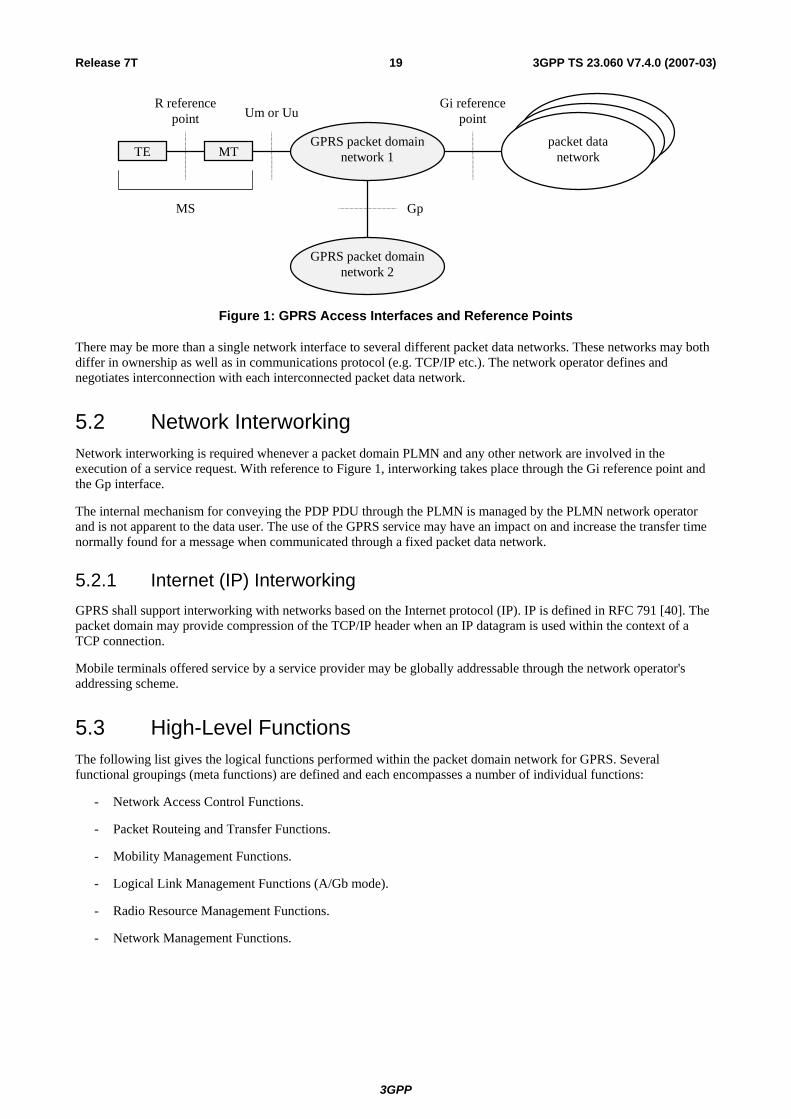
5.1 GPRS Access Interfaces and Reference Points Each PLMN has two access points to GPRS services, the radio interface (labelled Um in A/Gb mode and Uu in Iu mode) used for mobile access and the R reference point used for origination or reception of messages. The R reference point for the MSs is defined in TS 27.060 [17].
An interface differs from a reference point in that an interface is defined where specific information is exchanged and needs to be fully recognised.
There is an inter PLMN interface called Gp that connects two independent GPRS packet domain networks for message exchange.
There is also a PLMN to packet data network reference point called Gi. Gi is defined in TS 29.061 [27].
3GPP
Release 7T 19 3GPP TS 23.060 V7.4.0 (2007-03)
Gi referencepoint
GPRS packet domainnetwork 1
GPRS packet domainnetwork 2
packet datanetworkTE MT
Gp
Um or UuR reference
point
MS
Figure 1: GPRS Access Interfaces and Reference Points
There may be more than a single network interface to several different packet data networks. These networks may both differ in ownership as well as in communications protocol (e.g. TCP/IP etc.). The network operator defines and negotiates interconnection with each interconnected packet data network.
5.2 Network Interworking Network interworking is required whenever a packet domain PLMN and any other network are involved in the execution of a service request. With reference to Figure 1, interworking takes place through the Gi reference point and the Gp interface.
The internal mechanism for conveying the PDP PDU through the PLMN is managed by the PLMN network operator and is not apparent to the data user. The use of the GPRS service may have an impact on and increase the transfer time normally found for a message when communicated through a fixed packet data network.
5.2.1 Internet (IP) Interworking GPRS shall support interworking with networks based on the Internet protocol (IP). IP is defined in RFC 791 [40]. The packet domain may provide compression of the TCP/IP header when an IP datagram is used within the context of a TCP connection.
Mobile terminals offered service by a service provider may be globally addressable through the network operator's addressing scheme.
5.3 High-Level Functions The following list gives the logical functions performed within the packet domain network for GPRS. Several functional groupings (meta functions) are defined and each encompasses a number of individual functions:
- Network Access Control Functions.
- Packet Routeing and Transfer Functions.
- Mobility Management Functions.
- Logical Link Management Functions (A/Gb mode).
- Radio Resource Management Functions.
- Network Management Functions.
3GPP

Release 7T 20 3GPP TS 23.060 V7.4.0 (2007-03)
5.3.1 Network Access Control Functions Network access is the means by which a user is connected to a telecommunication network in order to use the services and/or facilities of that network. An access protocol is a defined set of procedures that enables the user to employ the services and/or facilities of the network.
User network access may occur from either the mobile side or the fixed side of the network. The fixed network interface may support multiple access protocols to packet data networks, for example IP. The set of access protocols to be supported is determined by the PLMN operator.
Individual PLMN administrations may require specific access-control procedures in order to limit the set of users permitted to access the network, or to restrict the capabilities of individual users, for example by limiting the type of service available to an individual subscriber. Such access control procedures are beyond the scope of the specifications.
5.3.1.1 Registration Function
Registration is the means by which a user's Mobile Id is associated with the user's packet data protocol(s) and address (es) within the PLMN, and with the user's access point(s) to the packet data network. The association can be static, i.e. stored in an HLR, or dynamic, i.e. allocated on a per need basis.
5.3.1.2 Authentication and Authorisation Function
This function performs the identification and authentication of the service requester, and the validation of the service request type to ensure that the user is authorised to use the particular network services. The authentication function is performed in association with the Mobility Management functions.
5.3.1.3 Admission Control Function
The purpose of admission control is to calculate which network resources are required to provide the quality of service (QoS) requested, determine if those resources are available, and then reserve those resources. Admission control is performed in association with the Radio Resource Management functions in order to estimate the radio resource requirements within each cell.
5.3.1.4 Message Screening Function
A screening function concerned with filtering out unauthorised or unsolicited messages is required. This should be supported through packet filtering functions. All types of message screening are left to the operators' control, e.g. by use of Internet firewalls.
5.3.1.5 Packet Terminal Adaptation Function
This function adapts data packets received / transmitted from/to terminal equipment to a form suitable for transmission by GPRS across the packet domain network.
5.3.1.6 Charging Data Collection Function
This function collects data necessary to support subscription and/or traffic fees.
5.3.1.7 Operator Determined Barring Function
The purpose of this function is to limit the service provider's financial risk with respect to new subscribers or to those who have not promptly paid their bills by restricting a particular packet switched service.
The functionality of ODB is described in the TS 23.015 [66].
3GPP

Release 7T 21 3GPP TS 23.060 V7.4.0 (2007-03)
5.3.2 Packet Routeing and Transfer Functions A route is an ordered list of nodes used for the transfer of messages within and between the PLMN(s). Each route consists of the originating node, zero or more relay nodes and the destination node. Routeing is the process of determining and using, in accordance with a set of rules, the route for transmission of a message within and between the PLMN(s).
5.3.2.1 Relay Function
The relay function is the means by which a node forwards data received from one node to the next node in the route.
5.3.2.2 Routeing Function
The routeing function determines the network node to which a message should be forwarded and the underlying service(s) used to reach that GPRS Support Node (GSN), using the destination address of the message. The routeing function selects the transmission path for the "next hop" in the route.
Data transmission between GSNs may occur across packet data networks that provide their own internal routeing functions, for example ITU-T Recommendation X.25 [34], Frame Relay or ATM networks.
5.3.2.3 Address Translation and Mapping Function
Address translation is the conversion of one address to another address of a different type. Address translation may be used to convert an packet data network protocol address into an internal network address that can be used for routeing packets within and between the PLMN(s).
Address mapping is used to map a network address to another network address of the same type for the routeing and relaying of messages within and between the PLMN(s), for example to forward packets from one network node to another.
5.3.2.4 Encapsulation Function
Encapsulation is the addition of address and control information to a data unit for routeing packets within and between the PLMN(s). Decapsulation is the removal of the addressing and control information from a packet to reveal the original data unit.
Encapsulation and decapsulation are performed between the GPRS support nodes, and between the GPRS serving support node and the MS.
5.3.2.5 Tunnelling Function
Tunnelling is the transfer of encapsulated data units within and between the PLMN(s) from the point of encapsulation to the point of decapsulation. A tunnel is a two-way point-to-point path. Only the tunnel endpoints are identified.
5.3.2.6 Compression Function
The compression function optimises use of radio path capacity by transmitting as little of the SDU (i.e. the exterior PDP PDU) as possible while at the same time preserving the information contained within it. Only IP header compression is supported in Iu mode. The GGSN may instruct the SGSN to negotiate no data compression for specific PDP contexts.
5.3.2.7 Ciphering Function
The ciphering function preserves the confidentiality of user data and signalling across the radio channels and inherently protects the PLMN from intruders.
5.3.2.8 Domain Name Server Function
The Domain Name Server function resolves logical GSN names to GSN addresses. This function is standard Internet functionality according to RFC 1034 [43], which allows resolution of any name for GSNs and other nodes within the GPRS packet domain PLMN backbone networks.
3GPP

Release 7T 22 3GPP TS 23.060 V7.4.0 (2007-03)
5.3.3 Mobility Management Functions The mobility management functions are used to keep track of the current location of an MS within the PLMN or within another PLMN.
5.3.4 Logical Link Management Functions (A/Gb mode) Logical link management functions are concerned with the maintenance of a communication channel between an individual MS and the PLMN across the radio interface. These functions involve the co-ordination of link state information between the MS and the PLMN as well as the supervision of data transfer activity over the logical link.
Refer to TS 44.064 [15] for further information.
5.3.4.1 Logical Link Establishment Function
Logical link establishment is performed when the MS attaches to the PS services.
5.3.4.2 Logical Link Maintenance Functions
Logical link maintenance functions supervise the logical link status and control link state changes.
5.3.4.3 Logical Link Release Function
The logical link release function is used to de-allocate resources associated with the logical link connection.
5.3.5 Radio Resource Management Functions Radio resource management functions are concerned with the allocation and maintenance of radio communication paths, and are performed by the Radio Access Network. Refer to TS 43.064 [11] and to TS 43.051 [74] for further information on GERAN. Refer to TS 25.301 [50] for further information on UTRAN.
5.3.6 Network Management Functions Network management functions provide mechanisms to support O&M functions related to GPRS.
5.4 Logical Architecture The GPRS Core Network functionality is logically implemented on two network nodes, the Serving GPRS Support Node and the Gateway GPRS Support Node. It is necessary to name a number of new interfaces. No inference should be drawn about the physical configuration on an interface from Figure 2.
3GPP

Release 7T 23 3GPP TS 23.060 V7.4.0 (2007-03)
Gf
Uu
Um
D
Gi
Gn
IuGc
CE
Gp
Gs
Signalling and Data Transfer Interface Signalling Interface
MSC/VLR
TE MT UTRAN TE PDN
GrIu
HLR
Other PLMN
SGSN
GGSN
Gd
SM-SC SMS-GMSC
SMS-IWMSC
GGSN
EIR SGSN
GnCGF
GaGa
Billing System
GbTE MT BSS
R
A R
CAMEL GSM-SCF
Ge
Figure 2: Overview of the GPRS Logical Architecture
5.4.1 GPRS Core Network Nodes A GPRS Support Node (GSN) contains functionality required to support GPRS functionality for GERAN and/or UTRAN. In one PLMN, there may be more than one GSN.
The Gateway GPRS Support Node (GGSN) is the node that is accessed by the packet data network due to evaluation of the PDP address. It contains routeing information for PS-attached users. The routeing information is used to tunnel N-PDUs to the MS's current point of attachment, i.e. the Serving GPRS Support Node. The GGSN may request location information from the HLR via the optional Gc interface. The GGSN is the first point of PDN interconnection with a PLMN supporting GPRS (i.e. the Gi reference point is supported by the GGSN). GGSN functionality is common for all types of RANs.
The Serving GPRS Support Node (SGSN) is the node that is serving the MS. The SGSN supports GPRS for A/Gb mode (i.e. the Gb interface is supported by the SGSN) and/or Iu-mode (i.e. the Iu interface is supported by the SGSN). At PS attach, the SGSN establishes a mobility management context containing information pertaining to e.g. mobility and security for the MS. At PDP Context Activation, the SGSN establishes a PDP context, to be used for routeing purposes, with the GGSN that the subscriber will be using.
The SGSN and GGSN functionalities may be combined in the same physical node, or they may reside in different physical nodes. The SGSN and the GGSN contain IP or other (operator's selection, e.g. ATM-SVC) routeing functionality, and they may be interconnected with IP routers. In Iu mode, the SGSN and RNC may be interconnected with one or more IP routers. When the SGSN and the GGSN are in different PLMNs, they are interconnected via the Gp interface. The Gp interface provides the functionality of the Gn interface, plus security functionality required for inter-PLMN communication. The security functionality is based on mutual agreements between operators.
The SGSN may send location information to the MSC/VLR via the optional Gs interface. The SGSN may receive paging requests from the MSC/VLR via the Gs interface.
The SGSN interfaces with the GSM-SCF for optional CAMEL control using Ge reference point. Depending on the result from the CAMEL interaction, the session and packet data transfer may proceed normally. Otherwise, interaction with the GSM-SCF continues as described in TS 23.078 [8b]. Only the GSM-SCF interworking points are indicated in the signalling procedures in this specification.
3GPP

Release 7T 24 3GPP TS 23.060 V7.4.0 (2007-03)
5.4.2 GPRS Packet Domain PLMN Backbone Networks There are two kinds of backbone networks. These are called:
- intra-PLMN backbone network; and
- inter-PLMN backbone network.
The intra-PLMN backbone network is the IP network interconnecting GSNs within the same PLMN and it interconnects GSNs with RNCs if Direct Tunnel functionality is supported.
The inter-PLMN backbone network is the IP network interconnecting GSNs and intra-PLMN backbone networks in different PLMNs.
BG
SGSN
BG
SGSN
GGSN GGSN
SGSN
Intra-PLMN BackboneIntra-PLMN Backbone
Gi Gp Gi
PLMN A PLMN B
Packet Data Network
Inter-PLMN Backbone
RNC RNC
Figure 3: Intra- and Inter-PLMN Backbone Networks
Every intra-PLMN backbone network is a private IP network intended for GPRS packet domain data and signalling only. A private IP network is an IP network to which some access control mechanism is applied in order to achieve a required level of security. Two intra-PLMN backbone networks are connected via the Gp interface using Border Gateways (BGs) and an inter-PLMN backbone network. The inter-PLMN backbone network is selected by a roaming agreement that includes the BG security functionality. The BG is not defined within the scope of GPRS. The inter-PLMN backbone can be a Packet Data Network, e.g. the public Internet or a leased line.
5.4.3 HLR The HLR contains GPRS subscription data and routeing information. The HLR is accessible from the SGSN via the Gr interface and from the GGSN via the Gc interface. For roaming MSs, the HLR may be in a different PLMN than the current SGSN.
5.4.4 SMS-GMSC and SMS-IWMSC The SMS-GMSC and SMS-IWMSC are connected to the SGSN via the Gd interface to enable the SGSN to support SMS.
3GPP

Release 7T 25 3GPP TS 23.060 V7.4.0 (2007-03)
5.4.5 Mobile Stations (A/Gb mode) An A/Gb mode MS operates in one of three modes of operation. The mode of operation depends on the network domains that the MS is attached to, i.e. only PS or both PS and CS domain, and upon the MS's capabilities to operate PS and CS domain services simultaneously.
- Class-A mode of operation: The MS is attached to both PS and CS domain, and the MS supports simultaneous operation of PS and CS domain services.
- Class-B mode of operation: The MS is attached to both PS and CS domain, but the MS can only operate one set of services, PS or CS services, at a time.
- Class-C mode of operation: The MS is exclusively attached to the PS domain.
The three modes of operation are defined in TS 22.060 [3].
NOTE: Other technical specifications may refer to the MS modes of operation as GPRS class-A MS, GPRS class-B MS, and GPRS class-C MS.
5.4.6 Mobile Stations (Iu mode) An Iu mode MS operates in one of three modes of operation. However, these operation modes are different from the ones of an A/Gb mode MS due to the capabilities of an Iu mode RAN to multiplex CS and PS connections, due to paging co-ordination for PS services and CS services that are offered by the CN or the UTRAN/GERAN-Iu, etc. The different Iu mode MS operation modes are defined as follows:
- CS/PS mode of operation: The MS is attached to both the PS domain and CS domain, and the MS is capable of simultaneously signallingwith the PS and CS core network domains. This mode of operation is comparable to the class-A mode of operation defined for A/Gb mode. The ability to operate CS and PS services simultaneously depends on the MS capabilities (for example an A/Gb mode MS of class B, which can not operate simultaneously CS and PS services, may have the same limitations when changing to Iu mode and CS/PS mode of operation).
- PS mode of operation: The MS is attached to the PS domain only and may only operate services of the PS domain. However, this does not prevent CS-like services to be offered over the PS domain (e.g. VoIP). This mode of operation is equivalent to the A/Gb mode GPRS class-C mode of operation.
- CS mode of operation: The MS is attached to the CS domain only and may only operate services of the CS domain. However, this does not prevent PS-like service to be offered over the CS domain. The CS mode of operation is outside the scope of this specification.
All combinations of different operation modes as described for A/Gb mode and Iu mode MSs shall be allowed for GERAN and UTRAN multisystem terminals.
5.4.7 Charging Gateway Functionality The Charging Gateway Functionality (CGF) is described in TS 32.251 [70].
3GPP

Release 7T 26 3GPP TS 23.060 V7.4.0 (2007-03)
5.5 Assignment of Functions to General Logical Architecture The functions identified in the functional model are assigned to the logical architecture.
Table 1: Mapping of Functions to Logical Architecture
Function A/Gb mode -
MS
Iu mode MS
A/Gb mode RAN
Iu mode RAN
A/Gb mode SGSN
Iu mode SGSN
GGSN HLR
Network Access Control: Registration X Authentication and Authorisation X X X X X Admission Control X X X X X X Message Screening X Packet Terminal Adaptation X X Charging Data Collection X X X Operator Determined Barring X X X Packet Routeing & Transfer: Relay X X X X X X X Routeing X X X X X X X Address Translation and Mapping X X X X X X Encapsulation X X X X X X Tunnelling X X X X Compression X X X X Ciphering X X X X X Mobility Management: X X X X X X Logical Link Management: Logical Link Establishment X X Logical Link Maintenance X X Logical Link Release X X Radio Resource Management: X X X X X
3GPP

Release 7T 27 3GPP TS 23.060 V7.4.0 (2007-03)
5.6 User and Control Planes
5.6.1 User Plane (A/Gb mode)
5.6.1.1 MS – GGSN
The user plane consists of a layered protocol structure providing user information transfer, along with associated information transfer control procedures (e.g. flow control, error detection, error correction and error recovery). The user plane independence of the Network Subsystem (NSS) platform from the underlying radio interface is preserved via the Gb interface. The following user plane is used in A/Gb mode.
Relay
NetworkService
GTP-U
Application
IP
SNDCP
LLC
RLC
MAC
GSM RF
SNDCP
LLC
BSSGP
L1bis
RLC
MAC
GSM RF
BSSGP
L1bis
Relay
L2
L1
IP
L2
L1
IP
GTP-U
IP
Um Gb Gn GiMS BSS SGSN GGSN
NetworkService
UDPUDP
Figure 4: User Plane for A/Gb mode
Legend:
- GPRS Tunnelling Protocol for the user plane (GTP-U): This protocol tunnels user data between GPRS Support Nodes in the backbone network. The GPRS Tunnelling Protocol shall encapsulate all PDP PDUs. GTP is specified in TS 29.060 [26].
- UDP carries GTP PDUs for protocols that do not need a reliable data link (e.g. IP), and provides protection against corrupted GTP PDUs. UDP is defined in RFC 768 [39].
- IP: This is the backbone network protocol used for routeing user data and control signalling. The backbone network may initially be based on the IPv4. Ultimately, IPv6 shall be used. When IPv6 is used in the backbone, then IPv4 shall also be supported. IPv4 is defined in RFC 791 [40] and IPv6 is defined in RFC 2460 [48].
- Subnetwork Dependent Convergence Protocol (SNDCP): This transmission functionality maps network-level characteristics onto the characteristics of the underlying network. SNDCP is specified in TS 44.065 [16].
- Logical Link Control (LLC): This layer provides a highly reliable ciphered logical link. LLC shall be independent of the underlying radio interface protocols in order to allow introduction of alternative GPRS radio solutions with minimum changes to the NSS. LLC is specified in TS 44.064 [15].
- Relay: In the BSS, this function relays LLC PDUs between the Um and Gb interfaces. In the SGSN, this function relays PDP PDUs between the Gb and Gn interfaces.
- Base Station System GPRS Protocol (BSSGP): This layer conveys routeing- and QoS-related information between the BSS and the SGSN. BSSGP does not perform error correction. BSSGP is specified in TS 48.018 [78].
- Network Service (NS): This layer transports BSSGP PDUs. NS is specified in TS 48.016 [20].
- RLC/MAC: This layer contains two functions: The Radio Link Control function provides a radio-solution-dependent reliable link. The Medium Access Control function controls the access signalling (request and grant) procedures for the radio channel, and the mapping of LLC frames onto the GSM physical channel. RLC/MAC is defined in TS 44.060 [77].
- GSM RF: As defined in 3GPP TS 45.xxx series.
3GPP

Release 7T 28 3GPP TS 23.060 V7.4.0 (2007-03)
5.6.1.2 GSN – GSN
UDP
L2
L1
IP
L2
L1
IP
UDP
Gn or GpGSN GSN
GTP-U GTP-U
Figure 5: User Plane for SGSN – GGSN and SGSN – SGSN Interfaces
Legend:
- GPRS Tunnelling Protocol for the user plane (GTP-U): This protocol tunnels user data between SGSNs and GGSNs (Gn), and between SGSNs in the backbone network (Gp).
- User Datagram Protocol (UDP): This protocol transfers user data between GSNs. UDP is defined in RFC 768.
5.6.2 User Plane (Iu mode)
5.6.2.1 MS – GGSN user plane with GERAN in Iu mode
The user plane for GERAN in Iu mode is described in TS 43.051 [74].
5.6.2.2 MS – GGSN user plane with UTRAN
L1
RLC
PDCP
MAC
E.g. , IP , PPP
Application
L1
RLC
PDCP
MAC L1
UDP/IP
GTP-U
L2
Relay
L1
UDP/IP L2
GTP - U
E .g. , IP , PPP
3G-SGSNUTRAN MS Iu-PSUu Gn Gi
3G - GGSN
L1
UDP/IP
GTP-U
L2
L1
UDP/IP
GTP-U
L2
Relay
Figure 6a: User Plane with UTRAN
3GPP

Release 7T 29 3GPP TS 23.060 V7.4.0 (2007-03)
Figure 6b: User Plane with UTRAN and Direct Tunnel
Legend:
- Packet Data Convergence Protocol (PDCP): This transmission functionality maps higher-level characteristics onto the characteristics of the underlying radio-interface protocols. PDCP provides protocol transparency for higher-layer protocols. PDCP supports e.g. IPv4, PPP and IPv6. Introduction of new higher-layer protocols shall be possible without any changes to the radio-interface protocols. PDCP provides protocol control information compression. PDCP is specified in TS 25.323 [57].
NOTE: Unlike in A/Gb mode, user data compression is not supported in Iu mode, because the data compression efficiency depends on the type of user data, and because many applications compress data before transmission. It is difficult to check the type of data in the PDCP layer, and compressing all user data requires too much processing.
- GPRS Tunnelling Protocol for the user plane (GTP-U): This protocol tunnels user data between UTRAN and the 3G-SGSN, and between the GSNs in the backbone network. GTP shall encapsulate all PDP PDUs. GTP is specified in TS 29.060 [26].
- SGSN controls the user plane tunnel establishment and may establish a Direct Tunnel between UTRAN and GGSN as shown in Figure 6b.
- UDP/IP: These are the backbone network protocols used for routeing user data and control signalling.
- Radio Link Control (RLC): The RLC protocol provides logical link control over the radio interface. There may be several simultaneous RLC links per MS. Each link is identified by a Bearer Id. RLC is defined in TS 25.322 [55].
- Medium Access Control (MAC): The MAC protocol controls the access signalling (request and grant) procedures for the radio channel. MAC is specified in TS 25.321 [60].
5.6.2.3 GSN – GSN
This user plane is the same as for A/Gb mode, see clause "GSN – GSN" above.
5.6.3 Control Plane The control plane consists of protocols for control and support of the user plane functions:
- controlling the GPRS network access connections, such as attaching to and detaching from GPRS;
- controlling the attributes of an established network access connection, such as activation of a PDP address;
- controlling the routeing path of an established network connection in order to support user mobility; and
- controlling the assignment of network resources to meet changing user demands.
3GPP

Release 7T 30 3GPP TS 23.060 V7.4.0 (2007-03)
The following control planes are used in both A/Gb mode and Iu mode unless specifically indicated.
5.6.3.1 MS – SGSN (A/Gb mode)
BSSGPRelay
GMM/SM
LLC
RLC
MAC
GSM RF
GMM/SM
LLC
BSSGP
L1bis
Um GbMS BSS SGSN
NetworkService
RLC
MAC
GSM RF L1bis
NetworkService
Figure 7: Control Plane MS - SGSN in A/Gb mode
Legend:
- GPRS Mobility Management and Session Management (GMM/SM): This protocol supports mobility management functionality such as GPRS attach, GPRS detach, security, routeing area update, location update, PDP context activation, and PDP context deactivation, as described in clauses "Mobility Management Functionality" and "PDP Context Activation, Modification, Deactivation, and Preservation Functions".
5.6.3.2 MS – SGSN (Iu mode)
NOTE: Control plane for GERAN in Iu mode is described in TS 43.051 [74].
RLC
RRC
L1
GMM /SM / SMS
RRC
MAC
L1
RANAP
L2
Relay
L1
L2
SGSNRNSMS Iu-PsUu
RLC
SCCP
SignallingBearer
MAC L1
SignallingBearer
RANAP
SCCP
G MM / SM / SMS
Figure 8: Control Plane MS - SGSN in Iu mode
Legend:
- Iu mode Mobility Management and Session Management (GMM/SM): GMM supports mobility management functionality such as attach, detach, security, and routeing area update, as described in clause "Mobility Management Functionality". SM supports PDP context activation and PDP context deactivation, as described in clause "PDP Context Activation, Modification, Deactivation, and Preservation Functions".
- SMS supports the mobile-originated and mobile-terminated short message service described in TS 23.040 [8].
- Radio Access Network Application Protocol (RANAP): This protocol encapsulates and carries higher-layer signalling, handles signalling between the 3G-SGSN and Iu mode RAN, and manages the GTP connections on the Iu interface. RANAP is specified in TS 25.413 [56b]. The layers below RANAP are defined in TS 25.412 [56] and TS 25.414 [64].
- Radio Link Control (RLC): The RLC protocol offers logical link control over the radio interface for the transmission of higher layer-signalling messages and SMS. RLC is defined in TS 25.322 [55].
3GPP

Release 7T 31 3GPP TS 23.060 V7.4.0 (2007-03)
5.6.3.3 SGSN - HLR
SCCP SCCP
GrSGSN HLR
TCAP
MAP
TCAP
MAP
SignallingBearer
SignallingBearer
Figure 9: Control Plane SGSN - HLR
Legend:
- Mobile Application Part (MAP): This protocol supports signalling exchange with the HLR, as defined in TS 29.002 [23], with enhancements for GPRS as described in the present document.
- TCAP and SCCP are the same protocols as used to support MAP in CS PLMNs.
- The Signalling Bearer is one of the signalling bearers specified in TS 29.202 [72].
5.6.3.4 SGSN - MSC/VLR
SCCP
Signallingbearer
Signallingbearer
SCCP
GsSGSN MSC/VLR
BSSAP+ BSSAP+
Figure 10: Control Plane SGSN - MSC/VLR
Legend:
- Base Station System Application Part + (BSSAP+): A subset of BSSAP procedures supports signalling between the SGSN and MSC/VLR, as described in clause "Mobility Management Functionality" and in TS 29.018 [25]. The requirements for the lower layers are specified in TS 29.016 [24].
5.6.3.5 SGSN - EIR
SCCP
Signallingbearer
Signallingbearer
SCCP
GfSGSN EIR
TCAP
MAP
TCAP
MAP
Figure 11: Control Plane SGSN - EIR
Legend:
- Mobile Application Part (MAP): This protocol supports signalling between the SGSN and the EIR, as described in clause "Identity Check Procedures".
3GPP

Release 7T 32 3GPP TS 23.060 V7.4.0 (2007-03)
5.6.3.6 SGSN - SMS-GMSC or SMS-IWMSC
SCCP
Signallingbearer
Signallingbearer
SCCP
GdSGSN SMS-MSC
TCAP
MAP
TCAP
MAP
Figure 12: Control Plane SGSN - SMS-GMSC and SGSN - SMS-IWMSC
Legend:
- Mobile Application Part (MAP): This protocol supports signalling between the SGSN and SMS-GMSC or SMS-IWMSC, as described in clause "Point-to-point Short Message Service".
5.6.3.7 GSN - GSN
UDP
L2
L1
IP
L2
L1
IP
UDP
Gn or GpGSN GSN
GTP-C GTP-C
Figure 13: Control Plane for SGSN – GGSN and SGSN – SGSN Interfaces
Legend:
- GPRS Tunnelling Protocol for the control plane (GTP-C): This protocol tunnels signalling messages between SGSNs and GGSNs (Gn), and between SGSNs in the backbone network (Gp).
- User Datagram Protocol (UDP): This protocol transfers signalling messages between GSNs. UDP is defined in RFC 768 [39].
5.6.3.8 GGSN - HLR
This optional signalling path allows a GGSN to exchange signalling information with an HLR. There are two alternative ways to implement this signalling path:
- If an SS7 interface is installed in the GGSN, the MAP protocol can be used between the GGSN and an HLR.
- If an SS7 interface is not installed in the GGSN, any GSN with an SS7 interface installed in the same PLMN as the GGSN can be used as a GTP-to-MAP protocol converter to allow signalling between the GGSN and an HLR.
5.6.3.8.1 MAP-based GGSN - HLR Signalling
SCCP
Signallingbearer
Signallingbearer
SCCP
GcGGSN HLR
TCAP
MAP
TCAP
MAP
Figure 14: Control Plane GGSN - HLR Using MAP
3GPP

Release 7T 33 3GPP TS 23.060 V7.4.0 (2007-03)
Legend:
- Mobile Application Part (MAP): This protocol supports signalling exchange with the HLR, as described in clause "Network-Requested PDP Context Activation Procedure".
5.6.3.8.2 GTP and MAP-based GGSN - HLR Signalling
Gn
UDP
L2
IP
GGSN
L1
L2
IP
GSN
GTP-C
L1
Signallingbearer
SCCP
MAP
Signallingbearer
SCCP
HLR
TCAP
MAPGTP-C
Gc
Interworking
TCAP
UDP
Figure 15: Control Plane GGSN - HLR Using GTP and MAP
Legend:
- GPRS Tunnelling Protocol for the control plane (GTP-C): This protocol tunnels signalling messages between the GGSN and the protocol-converting GSN in the backbone network.
- Interworking: This function provides interworking between GTP and MAP for GGSN - HLR signalling.
5.7 Functionality Needed for Mobile IP Using IPv4 To support the optional Mobile IP services, see TS 23.121 [54], efficiently by GPRS, Foreign Agent (FA) functionality needs to be provided in the GGSN. The interface between the GGSN and FA, including the mapping between the care of IP address and the GTP tunnel in the PLMN is not standardized as the GGSN and FA are considered to be one integrated node.
Mobile IP services need a Home Agent (HA). The HA is a router that tunnels datagrams to an FA. The FA de-tunnels the datagrams and sends them towards the MS that is in a PLMN. The HA maintains current location information for each of the departed users. The location of the HA is outside the scope of the 3GPP specifications.
The FA and HA functionality is specified in RFC 3344 [46].
5.8 Functionality for Intra Domain Connection of RAN Nodes to Multiple CN Nodes
The Intra Domain Connection of RAN Nodes to Multiple CN Nodes overcomes the strict hierarchy that restricts the connection of a RAN node to just one CN node, and hence also to one SGSN. This implies that a RAN node must be able to determine which of the SGSNs, covering the area where an MS is located, should receive the signalling and user traffic sent from an MS. To avoid unnecessary signalling in the core network, an MS that has attached to one SGSN, should generally continue to be served by this SGSN as long as the MS is in the radio coverage of the pool area, to which the SGSN is associated. The concept of pool area is a RAN based definition that comprises one or more RA(s) that, from a RAN perspective, are served by a certain group of CN nodes. This does not exclude that one or more of the SGSNs in this group serve RAs outside the pool area. This group of SGSNs is also referred to as an SGSN pool.
To enable the RAN node to determine which SGSN to select when forwarding messages from an MS, Intra Domain Connection of RAN Nodes to Multiple CN Nodes defines a routing mechanism (and other related functionality). Another routing mechanism (and other related functionality) is defined for the SGSNs that support the Intra Domain Connection of RAN Nodes to Multiple CN Nodes. The routing mechanism is required to find the correct old SGSN (from the multiple SGSNs that are associated with a pool area). When an MS roams out of the pool area and into the area of one or more SGSNs that do not know about the internal structure of the pool area where the MS roamed from, the new SGSN will send the Identification Request message or the SGSN Context Request message to an SGSN that is
3GPP

Release 7T 34 3GPP TS 23.060 V7.4.0 (2007-03)
believed to be the old SGSN. This SGSN, which is associated with the same pool area as the actual old SGSN, resolves the ambiguity of multiple SGSNs in the pool area and determines the correct old SGSN from the P-TMSI (or the TLLI). The received message is then relayed to the correct old SGSN (unless it is itself the correct old SGSN). The routing mechanism in both the SGSNs and the RAN nodes utilises the fact that every SGSN that serves a pool area must have its own unique value range of the P-TMSI parameter within the pool area.
The requirements on, and the detailed functionality needed to support, the Intra Domain Connection of RAN Nodes to Multiple CN Nodes are defined in TS 23.236 [73].
5.9 Functionality for network sharing Network sharing allows multiple network operators to share a radio access network. In a shared network, an MS that supports network sharing selects one of the operators and indicates it to the network. This allows the network to provide services from the selected operator. For an MS that does not support network sharing, the network may select the network operator that provides the services.
The functionality needed to support network sharing is defined in TS 23.251 [83].
6 Mobility Management Functionality
6.1 Definition of Mobility Management States The Mobility Management (MM) activities related to a subscriber are characterised by one of three different MM states. In A/Gb mode, the MM states for a GPRS subscriber are IDLE, STANDBY, and READY. In Iu mode, the MM states for a GPRS subscriber are PMM-DETACHED, PMM-IDLE, and PMM-CONNECTED. Each state describes a certain level of functionality and information allocated. The information sets held at the MS and the SGSN are denoted MM context.
The MM state relates only to GPRS MM activities of a subscriber. The MM state is independent of the number and state of PDP contexts for that subscriber.
6.1.1 Mobility Management States (A/Gb mode)
6.1.1.1 IDLE (GPRS) State
In GPRS IDLE state, the subscriber is not attached to GPRS mobility management. The MS and SGSN contexts hold no valid location or routeing information for the subscriber. The subscriber-related mobility management procedures are not performed.
The MS performs PLMN selection and cell selection and re-selection.
Data transmission to and from the mobile subscriber as well as the paging of the subscriber is not possible. The GPRS MS is seen as not reachable in this case.
In order to establish MM contexts in the MS and the SGSN, the MS shall perform the GPRS Attach procedure.
6.1.1.2 STANDBY State
In STANDBY state, the subscriber is attached to GPRS mobility management. The MS and SGSN have established MM contexts as described in clause "Information Storage".
Pages for data or signalling information transfers may be received. It is also possible to receive pages for the CS services via the SGSN. Data reception and transmission are not possible in this state.
The MS performs GPRS Routeing Area (RA) and GPRS cell selection and re-selection locally. The MS executes mobility management procedures to inform the SGSN when it has entered a new RA. The MS does not inform the SGSN on a change of cell in the same RA. Therefore, the location information in the SGSN MM context contains only the GPRS RAI for MSs in STANDBY state.
3GPP

Release 7T 35 3GPP TS 23.060 V7.4.0 (2007-03)
The MS may initiate activation or deactivation of PDP contexts while in STANDBY state. A PDP context shall be activated before data can be transmitted or received for this PDP context.
The SGSN may have to send data or signalling information to an MS in STANDBY state. The SGSN then sends a Paging Request in the routeing area where the MS is located if PPF is set. If PPF is cleared, then paging is not done. The MM state in the MS is changed to READY when the MS responds to the page, and in the SGSN when the page response is received. Also, the MM state in the MS is changed to READY when data or signalling information is sent from the MS and, accordingly, the MM state in the SGSN is changed to READY when data or signalling information is received from the MS.
The MS or the network may initiate the GPRS Detach procedure to move to the IDLE state. After expiry of the mobile reachable timer the SGSN may perform an implicit detach in order to return the MM contexts in the SGSN to IDLE state. The MM and PDP contexts may then be deleted.
6.1.1.3 READY State
In READY state, the SGSN MM context corresponds to the STANDBY MM context extended by location information for the subscriber on the cell level. The MS performs mobility management procedures to provide the network with the actual selected cell. GPRS cell selection and re-selection is done locally by the MS, or may optionally be controlled by the network.
An identifier of the cell, the Cell Global Identity including RAC and LAC, is included in the BSSGP header of the data packet from the MS; see TS 48.018 [78].
The MS may send and receive PDP PDUs in this state. The network initiates no GPRS pages for an MS in READY state. Pages for other services may be done via the SGSN. The SGSN transfers downlink data to the BSS responsible for the subscriber's actual GPRS cell.
The MS may activate or deactivate PDP contexts while in READY state.
Regardless if a radio resource is allocated to the subscriber or not, the MM context remains in the READY state even when there is no data being communicated. A timer supervises the READY state. An MM context moves from READY state to STANDBY state when the READY timer expires. In order to move from READY state to IDLE state, the MS initiates the GPRS Detach procedure.
3GPP
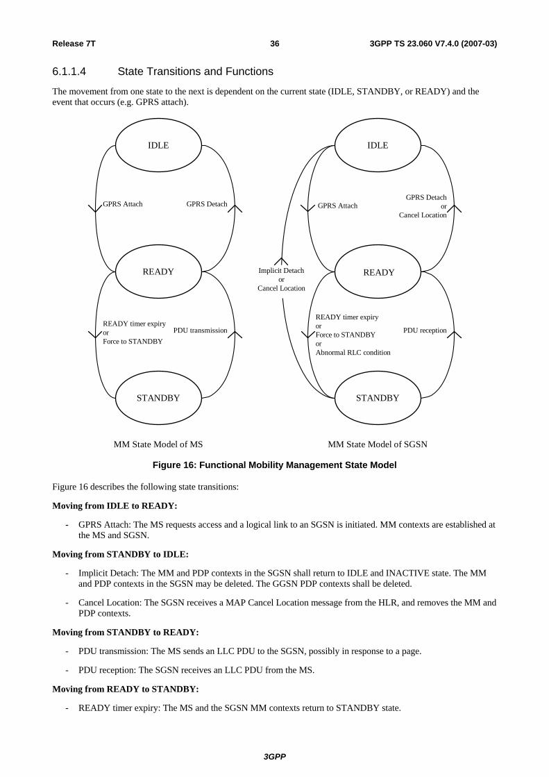
Release 7T 36 3GPP TS 23.060 V7.4.0 (2007-03)
6.1.1.4 State Transitions and Functions
The movement from one state to the next is dependent on the current state (IDLE, STANDBY, or READY) and the event that occurs (e.g. GPRS attach).
PDU transmission
Implicit Detachor
Cancel Location
GPRS Attach
READY timer expiryorForce to STANDBY
GPRS Detach GPRS Attach
PDU reception
GPRS Detachor
Cancel Location
MM State Model of MS MM State Model of SGSN
IDLE
READY
STANDBY
IDLE
READY
STANDBY
READY timer expiryorForce to STANDBYorAbnormal RLC condition
Figure 16: Functional Mobility Management State Model
Figure 16 describes the following state transitions:
Moving from IDLE to READY:
- GPRS Attach: The MS requests access and a logical link to an SGSN is initiated. MM contexts are established at the MS and SGSN.
Moving from STANDBY to IDLE:
- Implicit Detach: The MM and PDP contexts in the SGSN shall return to IDLE and INACTIVE state. The MM and PDP contexts in the SGSN may be deleted. The GGSN PDP contexts shall be deleted.
- Cancel Location: The SGSN receives a MAP Cancel Location message from the HLR, and removes the MM and PDP contexts.
Moving from STANDBY to READY:
- PDU transmission: The MS sends an LLC PDU to the SGSN, possibly in response to a page.
- PDU reception: The SGSN receives an LLC PDU from the MS.
Moving from READY to STANDBY:
- READY timer expiry: The MS and the SGSN MM contexts return to STANDBY state.
3GPP

Release 7T 37 3GPP TS 23.060 V7.4.0 (2007-03)
- Force to STANDBY: The SGSN indicates an immediate return to STANDBY state before the READY timer expires.
- Abnormal RLC condition: The SGSN MM context returns to STANDBY state in case of delivery problems on the radio interface or in case of irrecoverable disruption of a radio transmission.
Moving from READY to IDLE:
- GPRS Detach: The MS or the network requests that the MM contexts return to IDLE state and that the PDP contexts return to INACTIVE state. The SGSN may delete the MM and PDP contexts. The PDP contexts in the GGSN shall be deleted.
- Cancel Location: The SGSN receives a MAP Cancel Location message from the HLR, and removes the MM and PDP contexts.
6.1.2 Mobility Management States (Iu mode)
6.1.2.1 PMM-DETACHED State
In the PMM-DETACHED state there is no communication between the MS and the 3G-SGSN. The MS and SGSN contexts hold no valid location or routeing information for the MS. The MS MM state machine does not react on system information related to the 3G-SGSN. The MS is not reachable by a 3G-SGSN, as the MS location is not known.
In order to establish MM contexts in the MS and the SGSN, the MS shall perform the GPRS Attach procedure. When the PS signalling connection is established between the MS and the 3G-SGSN for performing the GPRS attach, the state changes to PMM-CONNECTED in the 3G-SGSN and in the MS. The PS signalling connection is made up of two parts: an RRC connection and an Iu connection.
6.1.2.2 PMM-IDLE State
The MS location is known in the 3G-SGSN with an accuracy of a routeing area. Paging is needed in order to reach the MS, e.g. for signalling. The MS and SGSN have established MM contexts as described in clause "Information Storage".
The MS shall perform a routeing area update if the RA changes. Signalling towards the HLR is needed if the 3G-SGSN does not have an MM context for this MS.
The MS and 3G-SGSN shall enter the PMM-CONNECTED state when the PS signalling connection is established between the MS and the 3G-SGSN.
GPRS detach changes the state to PMM-DETACHED. The 3G-SGSN may perform an implicit GPRS detach any time after the MS reachable timer expiry. The MS's MM context is deleted, preferably after a certain (implementation dependent) time. The HLR may be informed about the deletion (see clause "Purge Function").
6.1.2.3 PMM-CONNECTED State
The MS location is known in the 3G-SGSN with an accuracy of a serving RNC. In the PMM-CONNECTED state, the location of the MS is tracked by the serving RNC. The MS performs the routeing area update procedure when RAI in the MM system information changes.
When an MS and a 3G-SGSN are in the PMM-CONNECTED state, a PS signalling connection is established between the MS and the 3G-SGSN.
In the 3G-SGSN, PS signalling connection release or failed downlink transfer with cause "IMSI unknown in RNC" changes the state to PMM-IDLE.
The MS shall enter the PMM-IDLE state when its PS signalling connection to the 3G-SGSN has been released or broken. This release or failure is explicitly indicated by the RNC to the MS or detected by the MS (RRC connection failure). The radio connection shall also be released if a URA update fails because of "RRC connection not established", or if the URA update timer expires while the MS is out of coverage.
After a signalling procedure (e.g. routeing area update), the 3G-SGSN may decide to release the PS signalling connection, after which the state is changed to PMM-IDLE.
3GPP

Release 7T 38 3GPP TS 23.060 V7.4.0 (2007-03)
GPRS detach changes the state to PMM-DETACHED.
6.1.2.4 State Transitions and Functions
Figure 17 introduces the MM states for a GPRS subscriber (PMM). The states and activations are further described below the figure.
PM M -D ETAC H ED
PS Attach
PS S ignallingC onnection R elease
PS S ignallingC onnection Estab lish
PS D etach
PM M -C ONNE CTE DPM M -ID LE
D etach,PS Attach R eject,RAU R eject
PM M -D ETAC HED
PS D etach
PM M -C ONNE CTE D
S erv ing RNCrelocation
3G -SG SN MM StatesMS MM States
SM -ACTIV E orINA CTIVE
SM -ACTIV E orINA CTIVE
SM -ACTIV E orINA CTIVE
SM -ACTIV E orINA CTIVE
D etach,PS Attach R eject,RAU R ejectPS Attach
PS S ignallingC onnection Establish
PS S ignallingC onnection R eleas e
PM M -ID LE
Figure 17: PMM State Model
NOTE: In both the PMM-IDLE and the PMM-CONNECTED states, session management may or may not have activated a PDP context. The consequence is that in PMM-CONNECTED state, only a signalling connection may be established. In PMM-IDLE state, a PDP context may be established, but no corresponding connection over the Iu interface nor the radio are established.
Moving from PMM-DETACHED to PMM-CONNECTED in the MS:
- GPRS Attach: Th MM context shall move to the PMM-CONNECTED state when a PS signalling connection is established between the MS and the 3G-SGSN for performing a GPRS attach. If the GPRS attach is accepted an MM context is created in the MS.
Moving from PMM-CONNECTED to PMM-DETACHED in the MS:
- GPRS Detach: The MM context shall move to the PMM-DETACHED state when the PS signalling connection is released between the MS and the 3G-SGSN after the MS has performed a GPRS detach or after the network-initiated GPRS detach is performed. The MM context in the MS may be deleted.
- RAU Reject: The MM context shall move to the PMM-DETACHED state when the PS signalling connection is released between the MS and the 3G-SGSN after a RAU is rejected by the 3G-SGSN. The MM context may be deleted.
- GPRS Attach Reject: The MM context shall move to the PMM-DETACHED state when the PS signalling connection is released between the MS and the 3G-SGSN after a GPRS attach is rejected by the 3G-SGSN. The MM context may be deleted.
Moving from PMM-CONNECTED to PMM-IDLE in the MS:
- PS Signalling Connection Release: The MM context shall move to the PMM-IDLE state when the PS signalling connection is released.
Moving from PMM-IDLE to PMM-CONNECTED in the MS:
- PS Signalling Connection Establishment: The MM context shall move to the PMM-CONNECTED state when the PS signalling connection is established between the MS and the 3G-SGSN.
3GPP

Release 7T 39 3GPP TS 23.060 V7.4.0 (2007-03)
Moving from PMM-IDLE to PMM-DETACHED in the MS:
- Implicit GPRS Detach: The MM context shall locally move to the PMM-DETACHED state, e.g. in the case of removal of the battery, the USIM, or the GSIM from the TE.
Moving from PMM-DETACHED to PMM-CONNECTED in the 3G-SGSN:
- GPRS Attach: The MM context shall move to the PMM-CONNECTED state when a PS signalling connection is established between the MS and 3G-SGSN for performing a GPRS attach. If the GPRS attach is accepted, an MM context is created in the 3G-SGSN.
Moving from PMM-CONNECTED to PMM-DETACHED in the 3G-SGSN:
- GPRS Detach: The MM context shall move to the PMM-DETACHED state when the PS signalling connection is released between the MS and the 3G-SGSN after the MS has performed a GPRS detach or after the network-initiated GPRS detach is performed. The MM context in the 3G-SGSN may be deleted.
- RAU Reject: The MM context shall move to the PMM-DETACHED state when the PS signalling connection is released between the MS and the 3G-SGSN after a RAU is rejected.
- GPRS Attach Reject: The MM context shall move to the PMM-DETACHED state when a PS signalling connection is released between the MS and the 3G-SGSN after a GPRS attach is rejected by the 3G-SGSN.
Moving from PMM-CONNECTED to PMM-IDLE in the 3G-SGSN:
- PS Signalling Connection Release: The MM context shall move to the PMM-IDLE state when the PS signalling connection is released.
Moving from PMM-IDLE to PMM-CONNECTED in the 3G-SGSN:
- PS Signalling Connection Establishment: The MM context shall move to the PMM-CONNECTED state when the PS signalling connection is established.
Moving from PMM-IDLE to PMM-DETACHED in the 3G-SGSN:
- Implicit GPRS Detach: The MM context may locally move to the PMM-DETACHED state after expiry of the MS Reachable timer. The MM and PDP context(s) in the 3G-SGSN may be deleted, preferably after an implementation-dependent time.
6.1.2.4.1 Handling of Un-synchronous States in the UE and the Network
6.1.2.4.1.1 Unsynchronous PMM states in the UE and the SGSN
In case of RRC connection release with cause "Directed Signalling connection re-establishment" or in case of an error, the PMM state of the MS and the 3G-SGSN may lose synchronisation. In this case the MS may be in the PMM-IDLE state while the 3G-SGSN is in the PMM-CONNECTED state.
NOTE 1: The opposite (MS in the PMM-CONNECTED state and SGSN in the PMM-IDLE state) shall never happen because the 3G-SGSN may not have the RAI where the MS is really located, so downlink transfer is impossible until the periodic URA update timer expires.
This situation is recovered by a successful MS initiated connection establishment, e.g. for a RAU or for data transfer, or by a failed downlink transfer with cause "IMSI unknown in RNC", triggering a paging procedure from the 3G-SGSN.
If the SGSN in PMM-CONNECTED state receives Iu connection establishment request from the MS, the SGSN shall ensure the new Iu connection and the existing one are for the same MS, and if so the SGSN shall process the new request and release existing Iu connection and all RABs associated with it. To ensure that the new Iu connection and the existing one are for the same MS, the SGSN may perform the security functions. If Direct Tunnel was established for the MS the SGSN sends Update PDP Context Request(s) to the GGSN(s) concerned to establish the GTP tunnels between SGSN and GGSN(s) in case the Iu connection establishment request is for signalling only. The SGSN may immediately establish a new direct tunnel and send Update PDP Context Request(s) to the GGSN(s) concerned and include the RNC's Address for User Plane, downlink TEID for data in case the Iu connection establishment request is for data transfer.
3GPP

Release 7T 40 3GPP TS 23.060 V7.4.0 (2007-03)
The UE shall also perform a RAU procedure immediately on entering PMM-IDLE state when it has received a RRC Connection Release message with cause "Directed Signalling connection re-establishment" even if the RA has not changed since the last update. The UE shall perform a subsequent Service request procedure after successful completion of the RA Update procedure to re-establish the radio access bearer when it has pending user data to send.
NOTE 2: The RNC will send a RRC CONNECTION RELEASE message with cause "Directed Signalling Connection re-establishment" when it is unable to contact the SRNC to validate the UE due to lack of Iur connection (see TS 25.331 [52]).
6.1.2.4.1.2 Unsynchronous states in the UE and the UTRAN
In abnormal cases, the UTRAN can believe the UE is in the RRC-CONNECTED state while the UE is actually in the RRC-IDLE state.
Symptoms of this condition are that the UTRAN has an Iu interface connection to the SGSN and the UTRAN pages with the RNTI but receives no answer from the UE.
For UTRAN paging triggered by CS domain pages, the RNC should take the responsibility to recover this situation by re-paging with the Core Network Identity in the cells of that RNC which are in the Location Area indicated by the CN. A consequence of this re-paging is that it may lead to the RNC having two RRC connections for one UE but different RNTIs. To resolve this, when the RNC receives the Common ID message from the MSC, the RNC may request the release of the Iu-PS connection associated with any different RNTI previously associated with that IMSI.
6.2 Mobility Management Timer Functions
6.2.1 READY Timer Function (A/Gb mode) The READY timer function maintains the READY timer in the MS and SGSN. The READY timer controls the time an MS remains in READY state in the MS and the SGSN. The READY timer shall be reset and begin running in the MS when an LLC PDU is transmitted, and in the SGSN when an LLC PDU is correctly received. When the READY timer expires, the MS and SGSN MM contexts shall return to STANDBY state.
The length of the READY timer shall be the same in the MS and SGSN. The initial length of the READY timer shall be defined by a default value. The SGSN, and only the SGSN, may change the length of the READY timer by transmitting a new value in the Attach Accept or Routeing Area Update Accept messages.
If the READY timer length is set to zero, the MS shall immediately be forced into STANDBY state. If the timer length is set to all 1s (binary), the READY timer function shall be deactivated, i.e. the timer no longer runs and the MS remains in READY state.
6.2.2 Periodic RA Update Timer Function The Periodic RA Update Timer function monitors the periodic RA update procedure in the MS. The length of the periodic RA update timer is sent in the Routeing Area Update Accept or Attach Accept message. The periodic RA update timer is unique within an RA. Upon expiry of the periodic RA update timer, the MS shall start a periodic routeing area update procedure.
NOTE: An MS is said to be in GPRS coverage if it can access GPRS services. These services may be provided in A/Gb mode or in Iu mode.
If the MS is in coverage but out of GPRS coverage when the periodic RA update timer expires, then, if the MS is IMSI-attached to a network in network operation mode I, the periodic location update procedure (or other appropriate location update procedure) shall be started immediately. In addition, and irrespective of whether or not the MS was IMSI-attached, regardless of the network operation mode, the periodic RA update procedure (or other appropriate update procedure) shall be started as soon as the MS returns to GPRS coverage.
If the MS is out of coverage when the periodic RA update timer expires then:
- if the MS is both IMSI- and GPRS-attached and returns to coverage in a cell that supports packet-domain services in network operation mode I, then the combined RA / LA update procedure with IMSI attach requested shall be started as soon as the MS returns to coverage;
3GPP

Release 7T 41 3GPP TS 23.060 V7.4.0 (2007-03)
- if the MS is both IMSI- and GPRS-attached and returns to coverage in a cell that supports packet-domain services in network operation mode II or III, or if a GPRS only-attached MS returns to coverage in a cell that supports packet-domain services, then the periodic RA update procedure shall be started as soon as the MS returns to coverage; or
- if the MS returns to coverage in a cell that does not support packet-domain services, and if the MS is IMSI-attached, then the periodic location update procedure (or other appropriate location update procedure) shall be started as soon as the MS returns to coverage in that cell. In addition, and irrespective of whether or not the MS was IMSI-attached, the periodic RA update procedure (or other appropriate update procedure) shall be started as soon as the MS returns to packet-domain coverage.
If the MS lost packet-domain coverage but the periodic RA update timer did not expire while out of packet-domain coverage, then the MS shall not perform the periodic RA update procedure because of the MS's return to packet-domain coverage.
If the MS lost coverage but the periodic RA update timer did not expire while out of coverage, the MS shall not perform the periodic RA update procedure because of the MS's return to coverage.
6.2.3 Mobile Reachable Timer Function The Mobile Reachable Timer function monitors the periodic RA update procedure in the SGSN. The mobile reachable timer shall be slightly longer than the periodic RA update timer used by an MS.
The mobile reachable timer is stopped when the READY state or PMM-CONNECTED state is entered. The mobile reachable timer is reset and started when the state returns to STANDBY or PMM-IDLE.
If the mobile reachable timer expires, the SGSN shall clear PPF. Typically, in GPRS, this causes the SGSN to stop sending GPRS paging or CS paging messages to the MS, but other features (e.g. MSC/VLR-based call forwarding) may happen immediately. PPF is set when the next activity from the MS is detected. The MM and PDP contexts shall be kept in the SGSN.
When an MS first registers in an SGSN, then PPF is set.
6.3 Interactions Between SGSN and MSC/VLR The interactions described in this clause shall be supported if the optional Gs interface is installed. All functionality of this clause and sub-clauses applies for A/Gb mode and Iu mode unless stated differently.
An association is created between SGSN and MSC/VLR to provide for interactions between SGSN and MSC/VLR. The association is created when the VLR stores the SGSN number and the SGSN stores the VLR number. The association is used for co-ordinating MSs that are both GPRS-attached and IMSI-attached.
The association supports the following actions:
- IMSI attach and detach via SGSN. This makes combined GPRS / IMSI attach and combined GPRS / IMSI detach possible, thus saving radio resources.
- Co-ordination of LA update and RA update, including periodic updates, thus saving radio resources. A combined RA / LA update is sent from the MS to the SGSN. The SGSN forwards the LA update to the VLR.
- Paging for a CS connection via the SGSN.
- Alert procedures for non-PS services.
- Identification procedure.
- MM Information procedure.
- CS and PS registration coordination in networks that support network sharing as defined in TS 23.251 [83] so that a UE is registered with the same core network operator in the CS and PS domain.
3GPP

Release 7T 42 3GPP TS 23.060 V7.4.0 (2007-03)
6.3.1 Administration of the SGSN - MSC/VLR Association The SGSN - MSC/VLR association is created at the following occasions:
- Combined GPRS / IMSI attach.
- GPRS attach when the MS is already IMSI-attached.
- Combined RA / LA update when the MS performs IMSI attach and is already GPRS-attached.
- Combined RA / LA update when an IMSI and GPRS-attached MS changes from an area of network operation mode II or III to an area of network operation mode I.
The association is initiated by the SGSN. The SGSN creates an association by sending a BSSAP+ message concerning a particular MS to the VLR. An SGSN that does not provide functionality for Intra Domain Connection of RAN Nodes to Multiple CN Nodes uses the RAI to determine the VLR number. An SGSN that provides functionality for Intra Domain Connection of RAN Nodes to Multiple CN Nodes uses the RAI and a hash value from the IMSI to determine the VLR number. During a CS connection, an MS in class-B mode of operation (A/Gb mode) cannot perform GPRS attach nor routeing area updates, only MSs in class-A mode of operation can perform these procedures. If a GPRS attach was made during a CS connection, the association shall be initiated by a combined RA / LA update after the CS connection has been released.
The association is updated on the following occasions:
- When an MS changes VLR.
- When an MS changes SGSN.
The association is not updated during a CS connection.
When the MS is in idle mode (see GSM 03.22 [7] and TS 23.122 [7b]), the association is updated with the combined RA / LA updates procedure.
In relation to a CS connection, the association is managed in the following way:
MS in class-A or CS/PS mode of operation:
An MS in class-A or CS/PS mode of operation makes RA updates but no combined RA / LA updates during the CS connection. In the case when the MS changes SGSN, the SGSN (according to normal RA update procedures, see clause "Inter SGSN Routeing Area Update") updates the HLR and the GGSN, but not the VLR, about the new SGSN number.
In the case when the MS changes MSC during the CS connection, the subscriber data still remains in the old VLR until the CS connection is released and a combined RA / LA update or LA update is made. The association is also not updated during the CS connection.
After the CS connection has been released, a combined RA / LA update is performed (if there has been a change of RA, or if a GPRS attach was performed and the new cell indicates network operation mode I), and the association is updated according to combined RA / LA update procedures, see clause "Combined RA / LA Update Procedure". If the new cell indicates network operation mode II or III, then the MS performs an LA update.
MS in class-B mode of operation (A/Gb mode):
An MS in class-B mode of operation does not make any RA updates during a CS connection. The SGSN number therefore remains the same during the CS connection and does not need to be updated in the VLR. In the case when the MS changes MSC during the CS connection, the subscriber data still remains in the old VLR until the CS connection has been released and a combined RA / LA update or LA update is made. Therefore, the VLR number remains the same during the CS connection. After the CS connection has been released, the MS performs an RA update and an LA update if the RA has changed and the new cell indicates network operation mode II or III, or a combined RA / LA update if the RA has changed and the new cell indicates network operation mode I. The association is updated according to the combined RA / LA update procedures, see clauses "Inter SGSN Routeing Area Update" and "Combined RA / LA Update Procedure".
3GPP

Release 7T 43 3GPP TS 23.060 V7.4.0 (2007-03)
The SGSN - MSC/VLR association is removed at the following occasions:
- At IMSI detach.
- At GPRS detach.
When the MSC/VLR receives an LA update via the A or Iu interface from an MS for which an association exists, the MSC/VLR shall remove the association without notifying the SGSN. When the SGSN receives a (non-combined) RA update from an MS for which an association exists, the SGSN shall remove the association without notifying the MSC/VLR. When the MSC/VLR receives a BSSAP+ MS Unreachable message from the SGSN indicating that PPF is cleared, the state of the association shall not be changed at the MSC/VLR.
6.3.2 Combined RA / LA Updating When the MS is both IMSI and GPRS-attached, the LA and RA updating is done in a co-ordinated way to save radio resources if supported by the network operation mode. When the MS enters a new RA in network operation mode I, the MS sends a Routeing Area Update Request message to the SGSN, as described in clause "Combined RA / LA Update Procedure". The LA update is included in the RA update. The SGSN then forwards the LA update to the MSC/VLR. The MSC/VLR optionally returns a new VLR TMSI that is sent to the MS via the SGSN.
An MS in class-A mode of operation involved in a CS connection makes only RA updates and no combined RA / LA updates to the SGSN.
An MS in CS/PS mode of operation involved in a CS connection makes only RA updates and no combined RA / LA updates to the SGSN.
An MS in class-B mode of operation involved in a CS connection does not make any updates during the CS connection.
An MS in class-C mode of operation never makes combined RA / LA updates. MSs in CS mode of operation and MSs in PS mode of operation never make combined RA / LA updates.
6.3.3 CS Paging (A/Gb mode) When an MS is both IMSI and GPRS-attached in a network that operates in mode I, the MSC/VLR executes paging for circuit-switched services via the SGSN. If the MS is in STANDBY state, it is paged in the routeing area and in the null routeing area (see clause "Routeing Area Identity "). If the MS is in READY state, it is paged in the cell. A paging timer in the MSC supervises the paging procedure. The SGSN converts the MSC paging message into an SGSN paging message.
The CS Paging procedure is illustrated in figure 18. Each step is explained in the following list.
4. SABM (Paging Response) 5. SCCP Connection Request (Paging Response)
1. Page
3. Paging Request 2. Paging Request
MS BSS SGSN MSC/VLR
Figure 18: CS Paging Procedure in A/Gb mode
1) The SGSN receives a Page (IMSI, VLR TMSI, Channel Needed, Priority, Location Information) message from the MSC. Channel Needed is defined in TS 48.008 [18] and indicates to the MS which type of CS channel is needed to be requested in the response. VLR TMSI and Channel Needed are optional parameters. Priority is the circuit-switched paging priority parameter as defined in TS 48.008 [18].
2) The SGSN sends a BSSGP Paging Request (IMSI, TLLI, VLR TMSI, Area, Channel Needed, QoS) message to the BSS serving the MS. Area is derived from either the MS's MM context in the SGSN or, if no such information is available, from the Location Information received from the MSC/VLR. Area indicates a single cell for a READY state MS or a routeing area for a STANDBY state MS. VLR TMSI and Channel Needed are
3GPP

Release 7T 44 3GPP TS 23.060 V7.4.0 (2007-03)
included if received from the MSC. If Channel Needed was not received from the MSC, then a default Channel Needed parameter indicating circuit-switched paging is included by the SGSN. QoS indicates the priority of this Paging Request relative to other Paging Request messages buffered in the BSS. If the location area where the MS was last known to be located has an associated null routeing area, then the SGSN shall send an additional BSSGP Paging Request message to each BSS serving this null RA.
3) The BSS translates the incoming BSSGP Paging Request message into one radio Paging Request message per cell. If a dedicated radio resource is assigned to the MS in a cell, then the BSS transmits one Paging Request (VLR TMSI or IMSI, Channel Needed) message on this radio resource, without stopping possibly ongoing data transfers for the MS. Otherwise, the BSS pages the MS with one Paging Request (VLR TMSI or IMSI, Channel Needed) message on the appropriate paging channel in each addressed cell. This is described in TS 43.064 [11].
4) Upon receipt of a Paging Request message for a circuit-switched service the MS may accept to respond to this request and shall follow the CS procedures for paging response (random access, immediate assignment, and paging response) as specified in TS 24.008 [13].
5) When received at the BSS, the Paging Response message is sent to the MSC, which shall stop the paging response timer.
6.3.3.1 Paging Co-ordination in A/Gb mode
The network may provide co-ordination of paging for circuit-switched and packet-switched services. Paging co-ordination means that the network sends paging messages for circuit-switched services on the same channel as used for packet-switched services, i.e. on the GPRS paging channel or on the GPRS traffic channel, and the MS needs only to monitor that channel. Three network operation modes are defined:
- Network operation mode I: the network sends a CS paging message for a GPRS-attached MS, either on the same channel as the GPRS paging channel (i.e. the packet paging channel or the CCCH paging channel), or on a GPRS traffic channel. This means that the MS needs only to monitor one paging channel, and that it receives CS paging messages on the packet data channel when it has been assigned a packet data channel.
- Network operation mode II: the network sends a CS paging message for a GPRS-attached MS on the CCCH paging channel, and this channel is also used for GPRS paging. This means that the MS needs only to monitor the CCCH paging channel, but that e.g. CS paging continues on this paging channel even if the MS has been assigned a packet data channel, unless BSS paging co-ordination as described in 8.1.6 is active.
- Network operation mode III: the network sends a CS paging message for a GPRS-attached MS on the CCCH paging channel, and sends a GPRS paging message on either the packet paging channel (if allocated in the cell) or on the CCCH paging channel. This means that an MS that wants to receive pages for both circuit-switched and packet-switched services shall monitor both paging channels in the cell, if the packet-paging channel is allocated. The core network performs no paging co-ordination. See, however, also 8.1.6 for description of paging co-ordination on BSS level.
Table 2: Paging Channel Configuration in different Network Operation Modes for A/Gb mode without BSS paging co-ordination
Mode Circuit Paging Channel GPRS Paging Channel CN Paging co-ordination Packet Paging Channel Packet Paging Channel
I CCCH Paging Channel CCCH Paging Channel Yes Packet Data Channel Not Applicable
II CCCH Paging Channel CCCH Paging Channel No III CCCH Paging Channel Packet Paging Channel No
CCCH Paging Channel CCCH Paging Channel
For MSs with an SGSN – MSC/VLR association, which is established via the GS interface, all MSC-originated paging of GPRS-attached MSs shall go via the SGSN, thus allowing network co-ordination of paging. Paging co-ordination shall be made by the SGSN based on the IMSI, and is provided independently of whether the MS is in STANDBY or in READY state. The network operates in mode I.
When no SGSN – MSC/VLR association exists, all MSC-originated paging of GPRS-attached MSs shall go via the A interface, and co-ordination of paging cannot be performed by the core network. The network shall then either:
3GPP

Release 7T 45 3GPP TS 23.060 V7.4.0 (2007-03)
- operate in mode II, meaning that the packet common control channel shall not be allocated in the cell; or
- operate in mode III, meaning that the packet common control channel shall be used for GPRS paging when the packet paging channel is allocated in the cell.
The network operation mode (mode I, II, or III) shall be indicated as system information to MSs. For proper operation, the mode of operation should be the same in each cell of a routeing area.
Based on the mode of operation provided by the network, the MS can then choose, according to its capabilities, whether it can attach to GPRS services, to non-GPRS services, or to both.
6.3.4 CS Paging (Iu mode) When an MS is both IMSI- and GPRS-attached in a network that operates in mode I, the MSC/VLR executes paging for circuit-switched services via the SGSN.
In the MSC, a paging timer supervises the paging procedure.
The CS Paging procedure is illustrated in Figure 19. Each step is explained in the following list.
4. RRC Initial Direct Transfer (Paging Response) 5. RANAP Initial UE (Paging Response)
1. Page
3. Paging 2. Paging
MS BSS/RNS SGSN MSC/VLR
Figure 19: CS Paging Procedure in Iu mode
1) The SGSN receives a Page (IMSI, VLR TMSI, Location Information) message from the MSC. If VLR TMSI is omitted, the IMSI is used instead of the TMSI as a paging address at the radio interface. If location information is not included, the SGSN shall page the MS in all the cells served by the VLR and the SGSN, unless the SGSN has reliable information about the location of the MS.
2) The 3G-SGSN sends a RANAP Paging (IMSI, TMSI, Area, CN Domain Indicator) message to each RNS. IMSI is needed by the RNS in order to calculate the MS paging group and to identify the paged MS. TMSI is included if received from the MSC. Area indicates the area in which the MS is paged, and is derived from either the MS's MM context in the SGSN or, if no such information is available, from the Location Information received from the MSC/VLR. CN Domain Indicator indicates which domain (CS or PS) initiated the paging message, and in this case it must be set to "CS" by the SGSN.
3) For more details on the radio resource part of the paging procedure, see subclause "Paging Initiated by CN".
4) Upon receipt of a Paging Request message for a circuit-switched service, the MS responds to this request and returns the paging response as specified in TS 44.018 [85] in an RRC Initial Direct Transfer message as specified in TS 25.331 [52]. CN Domain Indicator is set to "CS" in the Initial Direct Transfer message.
5) When received at the RNS, the Paging Response message is sent in an RANAP Initial UE message to the MSC, which shall then stop the paging response timer.
6.3.4.1 Network Operation Modes for Iu mode
The network operation mode is used to indicate whether the Gs interface is installed or not. When the Gs interface is present, MSs initiate combined procedures.
3GPP

Release 7T 46 3GPP TS 23.060 V7.4.0 (2007-03)
Table 3: Network Operation Modes for Iu mode
Mode Network configuration Combined procedure by MT I Gs interface is present Yes
II Gs interface is not present No
The network operation mode (mode I or II) shall be indicated as system information to the MSs. For proper operation, the mode of operation should be the same in each cell of a routeing area.
Based on the mode of operation provided by the network, the MS deriveswhether to initiate combined update procedures or separate update procedures.
NOTE: Network operation modes I and II for Iu mode correspond to modes I and II for A/Gb mode, respectively. Mode III applies to A/Gb mode only, but not to Iu mode.
6.3.4a CS Paging (in case Selective RA Update) When an MS is both IMSI- and GPRS-attached in a network that operates in mode I, and the MSC/VLR executes paging for circuit-switched services via the SGSN that support Selective RA Update Procedure, if the MS is in STANDBY or PMM-IDLE state, the SGSN shall cause the page to be sent in all cells in the routeing area where the MS is located. This can include both A/Gb mode and Iu mode cells (see clause "Selective RA Update").
The CS Paging procedure in A/Gb mode is illustrated in figure 18 and the CS Paging procedure in Iu mode is illustrated in figure 19.
6.3.5 Non-GPRS Alert The MSC/VLR may request an SGSN to report activity from a specific MS. In this case, the MSC/VLR shall send a BSSAP+ Alert Request (IMSI) message to the SGSN where the MS is currently GPRS-attached.
Upon reception of the Alert Request (IMSI) message, the SGSN shall set NGAF. If NGAF is set for an MS, the SGSN shall inform the MSC/VLR when the next activity from that MS (and the MS is both IMSI- and GPRS-attached) is detected, and shall clear NGAF.
If the activity detected by the SGSN leads to a procedure towards the MSC/VLR, the SGSN shall just follow this procedure. If the activity detected by the SGSN does not lead to any procedure towards the MSC/VLR, the SGSN shall send an MS Activity Indication (IMSI) message towards the MSC/VLR.
6.3.6 MS Information Procedure When the MS is marked at the VLR as both IMSI- and GPRS-attached, the VLR may perform the MS Information procedure via the SGSN. If the information requested by the VLR in the MS Information procedure is known by the SGSN, then the SGSN shall return this information to the VLR without interrogating the MS.
If the information requested is MS identity information (e.g. IMEI) that is not known by the SGSN but is known by the MS, then the SGSN shall interrogate the MS in a similar manner to that described in clause "Identity Check Procedures".
In A/Gb mode, if the information requested is MS location information, then this indicates a request for Cell Global Identity and Cell Identity Age. In Iu mode, if the information requested is MS location information, then this indicates a request for Service Area Identity and Service Area Identity Age, and in this case if an Iu connection for the MS exists, then the SGSN shall use the Location Reporting procedure (see clause "Location Reporting Procedure") in order to retrieve the Service Area Identity.
The MS Information procedure is illustrated in Figure 20. Procedure steps are explained in the following list.
3GPP

Release 7T 47 3GPP TS 23.060 V7.4.0 (2007-03)
BSS/RNS SGSN MSC/VLR
1. MS Information Request
MS
2. Identity Request
5. MS Information Response
3. Identity Response
4. Location Reporting
Figure 20: MS Information Procedure
1) The MSC/VLR sends an MS Information Request (IMSI, Information Type) message to the SGSN. Information Type indicates the information that the MSC/VLR is requesting for that IMSI.
2) If the information requested is not known by the SGSN but should be known by the MS, then the SGSN interrogates the MS in a similar manner to that described in the subclause "Identity Check Procedures". The SGSN sends an Identity Request (Identity Type) message to the MS.
3) The MS responds with an Identity Response (Mobile Identity) message to the SGSN.
4) In Iu mode, if an Iu connection for the MS exists, then the SGSN shall use the Location Reporting procedure to retrieve the Service Area Identity. If the BSS/RNS cannot determine the current Service Area of the MS, it indicates in the Location Report message that the request could not be fulfilled and may report the Last Known Service Area with an indication of how long has past since the MS was known to be in the indicated Service Area.
5) The SGSN sends an MS Information Response (IMSI, Information) message to the MSC/VLR. Information contains the information requested by the MSC/VLR. If an Iu connection for MS exist and RAN node cannot determine current Service Area and Last Known Service Area is not reported, the SGSN shall include in the MS Information Response message the last successfully received Service Area Identity with time elapsed since it was saved by SGSN.
6.3.7 MM Information Procedure When the MS is marked at the VLR as both IMSI- and GPRS-attached, the VLR may perform the MM Information procedure via the SGSN. The MM Information procedure is typically used to inform the MS about such things as the network name and the local time zone of the mobile.
The MM Information procedure is illustrated in Figure 21.
BSS/RNS SGSN MSC/VLR
1. MM Information
MS
2. MM Information
Figure 21: MM Information Procedure
1) The SGSN receives an MM Information (IMSI, Information) message from the MSC/VLR. Information is the information that the MSC/VLR is sending to the MS.
2) The SGSN sends an MM Information (Information) message to the MS including the information received by the MSC/VLR.
6.4 MM Procedures In A/Gb mode, the MM procedures shall use the LLC and RLC/MAC protocols for message transmission across the Gb and Um interfaces. The MM procedures shall provide information to the underlying layers to enable reliable
3GPP

Release 7T 48 3GPP TS 23.060 V7.4.0 (2007-03)
transmission of MM messages on the Um interface. TS 43.064 [11] defines the mapping between LLC and the radio channels used.
In Iu mode, the MM procedures shall use the RANAP and RRC protocols for message transmission across the Iu and radio interfaces, respectively.
Furthermore, the MM procedures use MAP interfaces between SGSN and HLR (Gr), and between SGSN and EIR (Gf), and a BSSAP+ interface between SGSN and MSC/VLR (Gs).
User data can in general be transmitted during MM signalling procedures. In A/Gb mode, user data transmitted during attach, authentication, and routeing area update procedures may be lost and may therefore have to be retransmitted. In order to minimise the need for retransmission, the MS and SGSN should not transmit user data during attach and authentication procedures. In case of routeing area update procedures, the user data transfer is allowed with restriction specified in description of these procedures in sub-clauses 6.9.1.2 and 6.9.1.3.
6.5 GPRS Attach Function An MS shall perform a GPRS Attach to the SGSN in order to obtain access to the GPRS services. If the MS is connected in A/Gb mode, it shall perform an A/Gb mode GPRS Attach procedure. If the MS is connected via in Iu mode, it shall perform an Iu mode GPRS Attach procedure.
In the attach procedure, the MS shall provide its identity and an indication of which type of attach that is to be executed. The identity provided to the network shall be the MS's Packet TMSI (P-TMSI) or IMSI. P-TMSI and the RAI associated with the P-TMSI shall be provided if the MS has a valid P-TMSI. If the MS does not have a valid P-TMSI, the MS shall provide its IMSI.
During the Attach procedure, the MS provides its PS Handover capabilities as defined in TS 24.008 [13].
6.5.1 A/Gb mode GPRS Attach Procedure A GPRS attach is made to the SGSN. A GPRS-attached MS makes IMSI attach via the SGSN with the combined RA / LA update procedure if the network operation mode is I. In network operation modes II and III, or if the MS is not GPRS-attached, the MS makes an IMSI attach as already defined in A/Gb mode. An IMSI-attached MS in class-A mode of operation engaged in a CS connection shall use the (non-combined) GPRS Attach procedures when it performs a GPRS attach.
At the RLC/MAC layer, the MS shall identify itself with a Local or Foreign TLLI if the MS is already GPRS-attached and is performing an IMSI attach. Otherwise, the MS shall identify itself with a Foreign TLLI, or a Random TLLI if a valid P-TMSI is not available. The Foreign or Random TLLI is used as an identifier during the attach procedure until a new P-TMSI is allocated.
After having executed the GPRS attach, the MS is in READY state and MM contexts are established in the MS and the SGSN. The MS may then activate PDP contexts as described in clause "Activation Procedures".
An IMSI-attached MS that can only operate in class-C mode of operation shall follow the normal IMSI detach procedure before it makes a GPRS attach. A GPRS-attached MS in class-C mode of operation shall always perform a GPRS detach before it makes an IMSI attach.
If the network operates in mode I (see clause "Paging Co-ordination in A/Gb mode"), then an MS that is both GPRS-attached and IMSI-attached shall perform the Combined RA / LA Update procedures.
If the network operates in mode II or III, then a GPRS-attached MS that has the capability to be simultaneously GPRS-attached and IMSI-attached shall perform the (non-combined) Routeing Area Update procedures, and either:
- access the non-GPRS common control channels for CS operation (the way that CS operation is performed in parallel with GPRS operation is an MS implementation issue outside the scope of the present document); or
- if CS operation is not desired, depending on system information that defines whether or not explicit detach shall be used, either:
- avoid all CS signalling (in which case the MS may be implicitly IMSI detached after a while); or
3GPP

Release 7T 49 3GPP TS 23.060 V7.4.0 (2007-03)
- perform an explicit IMSI detach via the non-GPRS common control channels (if the MS was already IMSI-attached).
The Combined GPRS / IMSI Attach procedure is illustrated in Figure 22.
6.5.2 Iu mode GPRS Attach Procedure A GPRS-attached MS makes an IMSI attach via the SGSN with the combined RA / LA update procedure if the network operates in mode I. If the network operates in mode II, or if the MS is not GPRS-attached, the MS makes a normal IMSI attach. An IMSI-attached MS engaged in a CS connection shall use the (non-combined) GPRS Attach procedure when it performs a GPRS attach.
After having executed the GPRS attach, the MS is in the PMM-CONNECTED state and MM contexts are established in the MS and the SGSN. The MS may then activate PDP contexts as described in clause "Activation Procedures".
An IMSI-attached MS that cannot operate in CS/PS mode of operation shall follow the normal IMSI detach procedure before it makes a GPRS attach. A GPRS-attached MS that cannot operate in CS/PS mode of operation shall perform a GPRS detach before it makes an IMSI attach.
In networks that support network sharing as defined in TS 23.251 [83], the SGSN may be informed by the RNS about the identity of the selected core network operator when receiving the Attach Request message. If available, this information is stored in the SGSN MM context.
3GPP

Release 7T 50 3GPP TS 23.060 V7.4.0 (2007-03)
6.5.3 Combined GPRS / IMSI Attach procedure The Combined GPRS / IMSI Attach procedure is illustrated in Figure 22.
7c. Cancel Location Ack
7b. Cancel Location
3. Identity Response
2. Identification Response
2. Identification Request 1. Attach Request
5. IMEI Check
3. Identity Request
4. Authentication
7a. Update Location
MS RAN new SGSN old SGSN GGSN HLR EIRold
MSC/VLRnew
MSC/VLR
8d. Cancel Location Ack
8c. Cancel Location
8b. Update Location
8g. Update Location Ack
8e. Insert Subscriber Data
8f. Insert Subscriber Data Ack
7f. Insert Subscriber Data
8a. Location Update Request
8h. Location Update Accept
7h. Update Location Ack
7g. Insert Subscriber Data Ack
10. Attach Complete
9. Attach Accept
11. TMSI Reallocation Complete
C1
7d. Delete PDP Context Request
7e. Delete PDP Context Response
6. Delete PDP Context Request
6. Delete PDP Context Response
Figure 22: Combined GPRS / IMSI Attach Procedure
3GPP

Release 7T 51 3GPP TS 23.060 V7.4.0 (2007-03)
1) In A/Gb mode, the MS initiates the attach procedure by the transmission of an Attach Request (IMSI or P-TMSI and old RAI, Classmark, CKSN, Attach Type, DRX Parameters, old P-TMSI Signature) message to the SGSN. IMSI shall be included if the MS does not have a valid P-TMSI available. If the MS has a valid P-TMSI, then P-TMSI and the old RAI associated with P-TMSI shall be included. Classmark contains the MS's GPRS multislot capabilities and supported GPRS ciphering algorithms in addition to the existing classmark parameters defined in GSM 04.08. Attach Type indicates which type of attach is to be performed, i.e. GPRS attach only, GPRS Attach while already IMSI attached, or combined GPRS / IMSI attach. DRX Parameters indicates whether the MS uses discontinuous reception or not. If the MS uses discontinuous reception, then DRX Parameters also indicate when the MS is in a non-sleep mode able to receive paging requests and channel assignments. If the MS uses P-TMSI for identifying itself and if it has also stored its old P-TMSI Signature, then the MS shall include the old P-TMSI Signature in the Attach Request message.
For Iu mode, the MS initiates the attach procedure by the transmission of an Attach Request (IMSI or P-TMSI and old RAI, Core Network Classmark, KSI, Attach Type, old P-TMSI Signature, Follow On Request, DRX Parameters) message to the SGSN. IMSI shall be included if the MS does not have a valid P-TMSI available. If the MS uses P-TMSI for identifying itself and if it has also stored its old P-TMSI Signature, then the MS shall include the old P-TMSI Signature in the Attach Request message. If the MS has a valid P-TMSI, then P-TMSI and the old RAI associated with P-TMSI shall be included. KSI shall be included if the MS has valid security parameters. Core Network Classmark is described in clause "MS Network Capability". The MS shall set "Follow On Request" if there is pending uplink traffic (signalling or user data). The SGSN may use, as an implementation option, the follow on request indication to release or keep the Iu connection after the completion of the GPRS Attach procedure. Attach Type indicates which type of attach is to be performed, i.e. GPRS attach only, GPRS Attach while already IMSI attached, or combined GPRS / IMSI attach. DRX Parameters indicates whether or not the MS uses discontinuous reception and the DRX cycle length.
2) If the MS identifies itself with P-TMSI and the SGSN has changed since detach, the new SGSN sends an Identification Request (P-TMSI, old RAI, old P-TMSI Signature) to the old SGSN to request the IMSI. If the new SGSN provides functionality for Intra Domain Connection of RAN Nodes to Multiple CN Nodes, the new SGSN may derive the old SGSN from the old RAI and the old P-TMSI and send the Identification Request message to this old SGSN. Otherwise, the new SGSN derives the old SGSN from the old RAI. In any case the new SGSN will derive an SGSN that it believes is the old SGSN. This derived SGSN is itself the old SGSN, or it is associated with the same pool area as the actual old SGSN and it will determine the correct old SGSN from the P-TMSI and relay the message to that actual old SGSN. The old SGSN responds with Identification Response (IMSI, Authentication Triplets or Authentication Quintets). If the MS is not known in the old SGSN, the old SGSN responds with an appropriate error cause. The old SGSN also validates the old P-TMSI Signature and responds with an appropriate error cause if it does not match the value stored in the old SGSN.
3) If the MS is unknown in both the old and new SGSN, the SGSN sends an Identity Request (Identity Type = IMSI) to the MS. The MS responds with Identity Response (IMSI).
4) The authentication functions are defined in the clause "Security Function". If no MM context for the MS exists anywhere in the network, then authentication is mandatory. Ciphering procedures are described in clause "Security Function". If P-TMSI allocation is going to be done and the network supports ciphering, the network shall set the ciphering mode.
5) The equipment checking functions are defined in the clause "Identity Check Procedures". Equipment checking is optional.
6) If there are active PDP contexts in the new SGSN for this particular MS (i.e. the MS re-attaches to the same SGSN without having properly detached before), the new SGSN deletes these PDP contexts by sending Delete PDP Context Request (TEID) messages to the GGSNs involved. The GGSNs acknowledge with Delete PDP Context Response (TEID) messages.
7) If the SGSN number has changed since the GPRS detach, or if it is the very first attach, or if the Automatic Device Detection (ADD) function is supported and the IMEISV has changed (see [82] for ADD functional requirement), then the SGSN informs the HLR:
a) The SGSN sends an Update Location (SGSN Number, SGSN Address, IMSI, IMEISV) to the HLR. IMEISV is sent if the ADD function is supported.
b) The HLR sends Cancel Location (IMSI, Cancellation Type) to the old SGSN with Cancellation Type set to Update Procedure.
3GPP

Release 7T 52 3GPP TS 23.060 V7.4.0 (2007-03)
c) The old SGSN acknowledges with Cancel Location Ack (IMSI). If there are any ongoing procedures for that MS, the old SGSN shall wait until these procedures are finished before removing the MM and PDP contexts.
d) If there are active PDP contexts in the old SGSN for this particular MS, the old SGSN deletes these PDP contexts by sending Delete PDP Context Request (TEID) messages to the GGSNs involved.
e) The GGSNs acknowledge with Delete PDP Context Response (TEID) messages.
f) The HLR sends Insert Subscriber Data (IMSI, GPRS Subscription Data) to the new SGSN.
g) The new SGSN validates the MS's presence in the (new) RA. If due to regional subscription restrictions or access restrictions (see TS 23.221 [80] and TS 23.008 [79]) the MS is not allowed to attach in the RA, the SGSN rejects the Attach Request with an appropriate cause, and may return an Insert Subscriber Data Ack (IMSI, SGSN Area Restricted) message to the HLR. If subscription checking fails for other reasons, the SGSN rejects the Attach Request with an appropriate cause and returns an Insert Subscriber Data Ack (IMSI, Cause) message to the HLR. If the network supports the MOCN configuration for network sharing, the SGSN may, if the MS is not a 'Network Sharing Supporting MS', in this case decide to initiate redirection by sending a Reroute Command to the RNS, as described in TS 23.251 [83] instead of rejecting the Attach Request message. If all checks are successful then the SGSN constructs an MM context for the MS and returns an Insert Subscriber Data Ack (IMSI) message to the HLR.
h) The HLR acknowledges the Update Location message by sending an Update Location Ack to the SGSN after the cancelling of old MM context and insertion of new MM context are finished. If the Update Location is rejected by the HLR, the SGSN rejects the Attach Request from the MS with an appropriate cause. If the network supports the MOCN configuration for network sharing, the SGSN may, if the MS is not a 'Network Sharing Supporting MS', in this case decide to initiate redirection by sending a Reroute Command to the RNS, as described in TS 23.251 [83] instead of rejecting the Attach Request message.
8) If Attach Type in step 1 indicated GPRS Attach while already IMSI attached, or combined GPRS / IMSI attached, then the VLR shall be updated if the Gs interface is installed. When the SGSN does not provide functionality for the Intra Domain Connection of RAN Nodes to Multiple CN Nodes, the VLR number is derived from the RAI. When the SGSN provides functionality for Intra Domain Connection of RAN Nodes to Multiple CN Nodes, the SGSN uses the RAI and a hash value from the IMSI to determine the VLR number. The SGSN starts the location update procedure towards the new MSC/VLR upon receipt of the first Insert Subscriber Data message from the HLR in step 6d). This operation marks the MS as GPRS-attached in the VLR.
a) The SGSN sends a Location Update Request (new LAI, IMSI, SGSN Number, Location Update Type) message to the VLR. Location Update Type shall indicate IMSI attach if Attach Type indicated combined GPRS / IMSI attach. Otherwise, Location Update Type shall indicate normal location update. The VLR creates an association with the SGSN by storing SGSN Number. . In networks that support network sharing, the Location Update Request includes the identity of the selected core network operator if the SGSN has received this information from the RAN, as described in TS 23.251 [83].
b) If the LA update is inter-MSC, the new VLR sends Update Location (IMSI, new VLR) to the HLR.
c) If the LA update is inter-MSC, the HLR sends a Cancel Location (IMSI) to the old VLR.
d) The old VLR acknowledges with Cancel Location Ack (IMSI).
e) If the LA update is inter-MSC, the HLR sends Insert Subscriber Data (IMSI, subscriber data) to the new VLR.
f) The VLR acknowledges with Insert Subscriber Data Ack (IMSI).
g) After finishing the inter-MSC location update procedures, the HLR responds with Update Location Ack (IMSI) to the new VLR.
h) The VLR responds with Location Update Accept (VLR TMSI) to the SGSN.
9) The SGSN selects Radio Priority SMS, and sends an Attach Accept (P-TMSI, VLR TMSI, P-TMSI Signature, Radio Priority SMS) message to the MS. P-TMSI is included if the SGSN allocates a new P-TMSI.
10) If P-TMSI or VLR TMSI was changed, the MS acknowledges the received TMSI(s) by returning an Attach Complete message to the SGSN.
3GPP

Release 7T 53 3GPP TS 23.060 V7.4.0 (2007-03)
11) If VLR TMSI was changed, the SGSN confirms the VLR TMSI re-allocation by sending a TMSI Reallocation Complete message to the VLR.
If the Attach Request cannot be accepted, the SGSN returns an Attach Reject (IMSI, Cause) message to the MS. If the network supports the MOCN configuration for network sharing, the SGSN may, if the MS is not a 'Network Sharing Supporting MS', in this case decide to initiate redirection by sending a Reroute Command to the RNS, as described in TS 23.251 [83] instead of returning an Attach Reject (IMSI, Cause) message to the MS.
The CAMEL procedure call shall be performed, see referenced procedure in TS 23.078 [8b]:
C1) CAMEL_GPRS_Attach and CAMEL_PS_Notification.
They are called in the following order:
- The procedure CAMEL_GPRS_Attach is called. In Figure 22, the procedure returns as result "Continue".
- Then the procedure CAMEL_PS_Notification is called. The procedure returns as result "Continue".
6.6 Detach Function The GPRS Detach procedure allows:
- an MS to inform the network that it does not want to access the SGSN-based services any longer; and
- the network to inform an MS that it does not have access to the SGSN-based services any more.
The Detach function allows an MS to inform the network that it wants to make a GPRS and/or IMSI detach, and it allows the network to inform an MS that it has been GPRS-detached or IMSI-detached by the network.
The different types of detach are:
- IMSI detach;
- GPRS detach; and
- combined GPRS / IMSI detach (MS-initiated only).
The MS is detached either explicitly or implicitly:
- Explicit detach: The network or the MS explicitly requests detach.
- Implicit detach: The network detaches the MS, without notifying the MS, a configuration-dependent time after the mobile reachable timer expired, or after an irrecoverable radio error causes disconnection of the logical link.
In the explicit detach case, a Detach Request (Cause) is sent by the SGSN to the MS, or by the MS to the SGSN.
The MS can make an IMSI detach in one of two ways depending on whether it is GPRS-attached or not:
- A GPRS-attached MS sends a Detach Request message to the SGSN, indicating an IMSI detach. This can be made in combination with GPRS detach.
- An MS that is not GPRS-attached makes the IMSI detach as already defined in A/Gb mode or Iu mode.
In the MO Detach Request message there is an indication to tell if the detach is due to switch off or not. The indication is needed to know whether a Detach Accept message should be returned or not.
In the network-originated Detach Request message there may be an indication to tell the MS that it is requested to initiate GPRS Attach and PDP Context Activation procedures for the previously activated PDP contexts.
3GPP
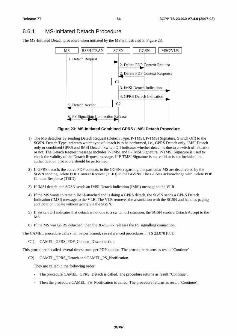
Release 7T 54 3GPP TS 23.060 V7.4.0 (2007-03)
6.6.1 MS-Initiated Detach Procedure The MS-Initiated Detach procedure when initiated by the MS is illustrated in Figure 23.
3. IMSI Detach Indication
2. Delete PDP Context Response
1. Detach Request 2. Delete PDP Context Request
5. Detach Accept
MS BSS/UTRAN GGSNSGSN MSC/VLR
4. GPRS Detach Indication
6. PS Signalling Connection Release
C2
C1
Figure 23: MS-Initiated Combined GPRS / IMSI Detach Procedure
1) The MS detaches by sending Detach Request (Detach Type, P-TMSI, P-TMSI Signature, Switch Off) to the SGSN. Detach Type indicates which type of detach is to be performed, i.e., GPRS Detach only, IMSI Detach only or combined GPRS and IMSI Detach. Switch Off indicates whether detach is due to a switch off situation or not. The Detach Request message includes P-TMSI and P-TMSI Signature. P-TMSI Signature is used to check the validity of the Detach Request message. If P-TMSI Signature is not valid or is not included, the authentication procedure should be performed.
2) If GPRS detach, the active PDP contexts in the GGSNs regarding this particular MS are deactivated by the SGSN sending Delete PDP Context Request (TEID) to the GGSNs. The GGSNs acknowledge with Delete PDP Context Response (TEID).
3) If IMSI detach, the SGSN sends an IMSI Detach Indication (IMSI) message to the VLR.
4) If the MS wants to remain IMSI-attached and is doing a GPRS detach, the SGSN sends a GPRS Detach Indication (IMSI) message to the VLR. The VLR removes the association with the SGSN and handles paging and location update without going via the SGSN.
5) If Switch Off indicates that detach is not due to a switch off situation, the SGSN sends a Detach Accept to the MS.
6) If the MS was GPRS detached, then the 3G-SGSN releases the PS signalling connection.
The CAMEL procedure calls shall be performed; see referenced procedures in TS 23.078 [8b]:
C1) CAMEL_GPRS_PDP_Context_Disconnection.
This procedure is called several times: once per PDP context. The procedure returns as result "Continue".
C2) CAMEL_GPRS_Detach and CAMEL_PS_Notification.
They are called in the following order:
- The procedure CAMEL_GPRS_Detach is called. The procedure returns as result "Continue".
- Then the procedure CAMEL_PS_Notification is called. The procedure returns as result "Continue".
3GPP

Release 7T 55 3GPP TS 23.060 V7.4.0 (2007-03)
6.6.2 Network-Initiated Detach Procedure
6.6.2.1 SGSN-Initiated Detach Procedure
The SGSN-Initiated Detach procedure when initiated by the SGSN is illustrated in Figure 24.
2. Delete PDP Context Response
1. Detach Request 2. Delete PDP Context Request
4. Detach Accept
MS BSS/UTRAN GGSNSGSN MSC/VLR
3. GPRS Detach Indication
5. PS Signalling Connection Release
C1
C2
Figure 24: SGSN-Initiated GPRS Detach Procedure
1) The SGSN informs the MS that it has been detached, by sending Detach Request (Detach Type) to the MS. Detach Type indicates if the MS is requested to make a new attach and PDP context activation for the previously activated PDP contexts. If so, the attach procedure shall be initiated when the detach procedure is completed.
2) The active PDP contexts in the GGSNs regarding this particular MS are deactivated by the SGSN sending Delete PDP Context Request (TEID) messages to the GGSNs. The GGSNs acknowledge with Delete PDP Context Response (TEID) messages.
3) If the MS was both IMSI- and GPRS-attached, the SGSN sends a GPRS Detach Indication (IMSI) message to the VLR. The VLR removes the association with the SGSN and handles paging and location update without going via the SGSN.
4) The MS sends a Detach Accept message to the SGSN any time after step 1.
5) After receiving the Detach Accept message, if Detach Type did not request the MS to make a new attach, then the 3G SGSN releases the PS signalling connection.
The CAMEL procedure calls shall be performed, see referenced procedure in TS 23.078 [8b]:
C1) CAMEL_GPRS_PDP_Context_Disconnection.
This procedure is called several times: once per PDP context. The procedure returns as result "Continue".
C2) CAMEL_GPRS_Detach and CAMEL_PS_Notification.
They are called in the following order:
- The procedure CAMEL_GPRS_Detach is called. The procedure returns as result "Continue".
- Then the procedure CAMEL_PS_Notification is called. The procedure returns as result "Continue".
3GPP

Release 7T 56 3GPP TS 23.060 V7.4.0 (2007-03)
6.6.2.2 HLR-Initiated Detach Procedure
The HLR-Initiated Detach procedure is initiated by the HLR. The HLR uses this procedure for operator-determined purposes to request the removal of a subscriber's MM and PDP contexts at the SGSN. The HLR-Initiated Detach Procedure is illustrated in Figure 25.
HLRMS BSS/UTRAN GGSNSGSN MSC/VLR
3. Delete PDP Context Request
1. Cancel Location
4. GPRS Detach Indication
2. Detach Request
6. Cancel Location Ack
3. Delete PDP Context Response
5. Detach Accept
7. PS Signalling Connection Release
C2
C1
Figure 25: HLR-Initiated GPRS Detach Procedure
1) If the HLR wants to request the immediate deletion of a subscriber's MM and PDP contexts from the SGSN, the HLR shall send a Cancel Location (IMSI, Cancellation Type) message to the SGSN with Cancellation Type set to Subscription Withdrawn.
2) The SGSN informs the MS that it has been detached by sending Detach Request (Detach Type) to the MS. Detach Type shall indicate that the MS is not requested to make a new attach and PDP context activation.
3) The active PDP contexts in the GGSNs regarding this particular MS are deactivated by the SGSN sending Delete PDP Context Request (TEID) messages to the GGSNs. The GGSNs acknowledge with Delete PDP Context Response (TEID) messages.
4) If the MS was both IMSI- and GPRS-attached, the SGSN sends a GPRS Detach Indication (IMSI) message to the VLR. The VLR removes the association with the SGSN and handles paging and location update without going via the SGSN.
5) The MS sends a Detach Accept message to the SGSN any time after step 2.
6) The SGSN confirms the deletion of the MM and PDP contexts with a Cancel Location Ack (IMSI) message.
7) After receiving the Detach Accept message, if Detach Type did not request the MS to make a new attach, then the 3G-SGSN releases the PS signalling connection.
The CAMEL procedure calls shall be performed, see referenced procedures in TS 23.078 [8b]:
C1) CAMEL_GPRS_PDP_Context_Disconnection.
This procedure is called several times: once per PDP context. The procedure returns as result "Continue".
C2) CAMEL_GPRS_Detach and CAMEL_PS_Notification.
They are called in the following order:
- The procedure CAMEL_GPRS_Detach is called. The procedure returns as result "Continue".
- Then the procedure CAMEL_PS_Notification is called. The procedure returns as result "Continue".
3GPP

Release 7T 57 3GPP TS 23.060 V7.4.0 (2007-03)
6.7 Purge Function The Purge function allows an SGSN to inform the HLR that it has deleted the MM and PDP contexts of a detached MS. The SGSN may, as an implementation option, delete the MM and PDP contexts of an MS immediately after the implicit or explicit detach of the MS. Alternatively, the SGSN may keep for some time the MM and PDP contexts and the authentication triplets of the detached MS, so that the contexts can be reused at a later GPRS attach without accessing the HLR.
When the SGSN deletes the MM and PDP contexts, it shall initiate the Purge procedure as illustrated in Figure 26.
1. Purge MS
2. Purge MS Ack
SGSN HLR
Figure 26: Purge Procedure
1) After deleting the MM and PDP contexts of a detached MS, the SGSN sends a Purge MS (IMSI) message to the HLR.
2) The HLR sets the MS Purged for GPRS flag and acknowledges with a Purge MS Ack message.
6.8 Security Function The Security function:
- Guards against unauthorised packet-domain service usage (authentication of the MS by the network and service request validation).
- Provides user identity confidentiality (temporary identification and ciphering).
- Provides user data and signalling confidentiality (ciphering).
- Provides, for Iu mode only, data integrity and origin authentication of signalling data (integrity protection).
- Provides, by UMTS authentication (USIM) only, authentication of the network by the MS.
Security-related network functions are described in TS 43.020 [6] and in TS 33.102 [61].
6.8.1 Authentication The Authentication function includes two types of authentication: "UMTS authentication" and "GSM authentication". These procedures are independent of the RAN modes, i.e. each procedure may be executed in A/Gb mode or in Iu mode. UMTS authentication requires a USIM for the MS and Authentication Quintets in the SGSN. GSM authentication bases on a SIM for the MS and Authentication Triplets in the SGSN or it bases on a GSM capable USIM for the MS and parameters derived from Authentication Quintets in the SGSN.
"UMTS authentication" implies mutual authentication, i.e. authentication of the MS by the network and authentication of the network by the MS. It also implies establishment of a new UMTS ciphering key (CK) and integrity key (IK) agreement between the SGSN and the MS.
"GSM authentication" implies authentication of the MS by the network and establishment of a new GSM ciphering key (Kc) agreement between the SGSN and the MS.
6.8.1.1 GSM Authentication procedure
The GSM Authentication procedure performs subscriber authentication, or selection of the ciphering algorithm, or both. In A/Gb mode it performs in addition the synchronisation of the start of ciphering. Authentication triplets are stored in the SGSN. The MSC/VLR shall not authenticate the MS via the SGSN upon IMSI attach, nor location update, but may
3GPP

Release 7T 58 3GPP TS 23.060 V7.4.0 (2007-03)
authenticate the MS during CS connection establishment. Security-related network functions are described in TS 43.020 [6].
The GSM Authentication procedure is illustrated in Figure 27.
1. Send Authentication Info
2. Authentication and Ciphering Request 1. Send Authentication Info Ack
2. Authentication and Ciphering Response
MS RAN HLRSGSN
Figure 27: GSM Authentication Procedure
1) If the SGSN does not have a previously stored authentication vector, a Send Authentication Info (IMSI) message is sent to the HLR. The HLR responds with a Send Authentication Info Ack (Authentication Triplets or quintets) message.
2) The SGSN sends an Authentication and Ciphering Request (RAND, CKSN, Ciphering Algorithm) message to the MS. The MS responds with an Authentication and Ciphering Response (SRES) message.
In A/Gb mode, the MS starts ciphering after sending the Authentication and Ciphering Response message as described in clause "Start of Ciphering".
Change of the ciphering algorithm during PS Handover procedure is described in TS 43.129 [87].
In Iu mode, the SGSN and the MS shall generate the UMTS CK and IK from the GSM Kc using the standardised conversion functions specified for this purpose in TS 33.102 [61].
In Iu mode, the start of ciphering is controlled by the security mode procedure described in TS 33.102 [61].
If the SGSN cannot determine the HLR address to establish the Send Authentication Info dialogue, the GSM Authentication of Procedure fails.
6.8.1.2 UMTS Authentication procedure
The UMTS authentication procedure is described in TS 33.102 [61]. The UMTS authentication procedure executed from the SGSN performs both the mutual authentication and security keys agreement. Authentication quintets are stored in the SGSN. The MSC/VLR shall not authenticate the MS via the SGSN upon IMSI attach nor upon location update, but may authenticate the MS during CS connection establishment.
3GPP

Release 7T 59 3GPP TS 23.060 V7.4.0 (2007-03)
The UMTS Authentication procedure is illustrated in Figure 28.
1. Send Authentication Info
2. Authentication and Ciphering Request 1. Send Authentication Info Ack
3. Authentication and Ciphering Response
MS RAN HLRSGSN
Figure 28: UMTS Authentication
1) If the SGSN does not have previously stored UMTS Authentication Vectors (quintets), a Send Authentication Info (IMSI) message is sent to the HLR. Upon receipt of this message, the HLR responds with a Send Authentication Info Ack message including an ordered array of quintets to the SGSN. Each quintet contains RAND, XRES, AUTN, CK, and IK. The generation of quintets in HLR is performed as specified in TS 33.102 [61].
2) At authentication, the SGSN selects the next in-order quintet and transmits the RAND and AUTN, that belong to this quintet, to the MS in the Authentication and Ciphering Request (RAND, AUTN, KSI) message. The SGSN also selects a Key Set Identifier, KSI, and includes this in the message.
3) At reception of this message, the USIM in the MS verifies AUTN and, if accepted, the USIM computes the signature of RAND, RES, in accordance with TS 33.102 [61]. If the USIM considers the authentication as being successful, the MS returns an Authentication and Ciphering Response (RES) message to the SGSN. During generation of authentication vectors, the USIM in the MS also computes a new Ciphering Key, CK, and a new Integrity Key, IK. These keys are stored together with the KSI until KSI is updated at the next authentication.
If the USIM considers the authentication being unsuccessful, e.g., in case of an authentication synchronisation failure, the MS returns the Authentication and Ciphering Failure message to the SGSN. The actions then taken are described in TS 33.102 [61].
In A/Gb mode, the SGSN and the MS shall generate the Kc from the UMTS CK and IK using the standardised conversion function specified for this purpose in TS 33.102 [61].
In A/Gb mode, the MS starts ciphering after sending the Authentication and Ciphering Response message as described in clause "Start of Ciphering".
In Iu mode, the start of ciphering is controlled by the security mode procedure described in TS 33.102 [61].
If the SGSN cannot determine the HLR address to establish the Send Authentication Info dialogue, the UMTS Authentication Procedure fails.
6.8.2 User Identity Confidentiality
6.8.2.1 User Identity Confidentiality (A/Gb mode)
A Temporary Logical Link Identity (TLLI) identifies a user in A/Gb mode. The relationship between TLLI and IMSI is known only in the MS and in the SGSN. TLLI is derived from the P-TMSI allocated by the SGSN or built by the MS as described in clause "NSAPI and TLLI for A/Gb mode".
6.8.2.2 User Identity Confidentiality (Iu mode)
A Radio Network Temporary Identity (RNTI) identifies a user between the MS and an Iu mode RAN. The relationship between RNTI and IMSI is known only in the MS and in the RAN. A P-TMSI identifies a user between the MS and the SGSN. The relationship between P-TMSI and IMSI is known only in the MS and in the SGSN.
3GPP

Release 7T 60 3GPP TS 23.060 V7.4.0 (2007-03)
6.8.2.3 P-TMSI Signature
P-TMSI Signature is optionally sent by the SGSN to the MS in Attach Accept and Routeing Area Update Accept messages. If the P-TMSI Signature has been sent by the SGSN to the MS since the current P-TMSI was allocated, then the MS shall include the P-TMSI Signature in the next Routeing Area Update Request, Detach Request, and Attach Request for identification checking purposes. If the P-TMSI Signature was sent, then the SGSN shall compare the P-TMSI Signature sent by the MS with the signature stored in the SGSN. If the values do not match, the SGSN should use the security functions to authenticate the MS. If the values match or if the P-TMSI Signature is missing, the SGSN may use the security functions to authenticate the MS. The P-TMSI Signature parameter has only local significance in the SGSN that allocated the signature.
If the network supports ciphering, the SGSN shall send the P-TMSI Signature ciphered to the MS. Routeing Area Update Request and Attach Request, into which the MS includes the P-TMSI Signature, are not ciphered.
6.8.2.4 P-TMSI Reallocation Procedure
The SGSN may reallocate the P-TMSI at any time. The reallocation procedure can be performed by the P-TMSI Reallocation procedure, or it can be included in the Attach or Routeing Area Update procedures. The P-TMSI reallocation during PS Handover procedure is described in TS 43.129 [87].
The P-TMSI Reallocation procedure is illustrated in Figure 29.
2. P-TMSI Reallocation Complete
1. P-TMSI Reallocation Command
MS BSS/UTRAN SGSN
Figure 29: P-TMSI Reallocation Procedure
1) The SGSN sends a P-TMSI Reallocation Command (new P-TMSI, P-TMSI Signature, RAI) message to the MS. P-TMSI Signature is an optional parameter that the MS, if received, shall return to the SGSN in the next Attach and Routeing Area Update procedures.
2) The MS returns a P-TMSI Reallocation Complete message to the SGSN.
6.8.3 User Data and GMM/SM Signalling Confidentiality
6.8.3.1 Scope of Ciphering
In A/Gb mode, the scope of ciphering is from the ciphering function in the SGSN to the ciphering function in the MS. Ciphering is done in the LLC layer, and from the perspective of the A/Gb mode MS-BTS radio path, an LLC PDU is transmitted as plain text.
In Iu mode, the scope of ciphering is from the ciphering function in the RAN to the ciphering function in the MS.
MS BSS/UTRAN SGSN
Scope of GPRS ciphering
Scope of UMTS ciphering
Figure 30: Scope of Ciphering
3GPP
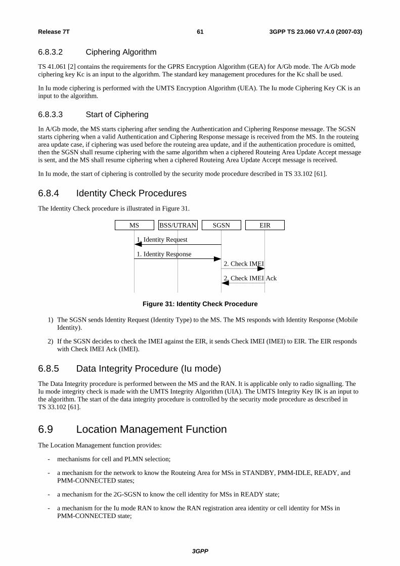
Release 7T 61 3GPP TS 23.060 V7.4.0 (2007-03)
6.8.3.2 Ciphering Algorithm
TS 41.061 [2] contains the requirements for the GPRS Encryption Algorithm (GEA) for A/Gb mode. The A/Gb mode ciphering key Kc is an input to the algorithm. The standard key management procedures for the Kc shall be used.
In Iu mode ciphering is performed with the UMTS Encryption Algorithm (UEA). The Iu mode Ciphering Key CK is an input to the algorithm.
6.8.3.3 Start of Ciphering
In A/Gb mode, the MS starts ciphering after sending the Authentication and Ciphering Response message. The SGSN starts ciphering when a valid Authentication and Ciphering Response message is received from the MS. In the routeing area update case, if ciphering was used before the routeing area update, and if the authentication procedure is omitted, then the SGSN shall resume ciphering with the same algorithm when a ciphered Routeing Area Update Accept message is sent, and the MS shall resume ciphering when a ciphered Routeing Area Update Accept message is received.
In Iu mode, the start of ciphering is controlled by the security mode procedure described in TS 33.102 [61].
6.8.4 Identity Check Procedures The Identity Check procedure is illustrated in Figure 31.
1. Identity Response 2. Check IMEI
1. Identity Request
2. Check IMEI Ack
MS BSS/UTRAN EIRSGSN
Figure 31: Identity Check Procedure
1) The SGSN sends Identity Request (Identity Type) to the MS. The MS responds with Identity Response (Mobile Identity).
2) If the SGSN decides to check the IMEI against the EIR, it sends Check IMEI (IMEI) to EIR. The EIR responds with Check IMEI Ack (IMEI).
6.8.5 Data Integrity Procedure (Iu mode) The Data Integrity procedure is performed between the MS and the RAN. It is applicable only to radio signalling. The Iu mode integrity check is made with the UMTS Integrity Algorithm (UIA). The UMTS Integrity Key IK is an input to the algorithm. The start of the data integrity procedure is controlled by the security mode procedure as described in TS 33.102 [61].
6.9 Location Management Function The Location Management function provides:
- mechanisms for cell and PLMN selection;
- a mechanism for the network to know the Routeing Area for MSs in STANDBY, PMM-IDLE, READY, and PMM-CONNECTED states;
- a mechanism for the 2G-SGSN to know the cell identity for MSs in READY state;
- a mechanism for the Iu mode RAN to know the RAN registration area identity or cell identity for MSs in PMM-CONNECTED state;
3GPP

Release 7T 62 3GPP TS 23.060 V7.4.0 (2007-03)
- a mechanism for the Iu mode RAN to indicate to an MS in RRC Connected mode when a Routeing Area Update procedure shall be performed by providing the RAI; and
- a mechanism for the network in Iu mode to know the address of the serving BSC/RNC handling an MS in PMM-CONNECTED state. This mechanism is the serving RNC relocation procedure.
NOTE: The SGSN may not know the Routeing Area where the Iu mode MS is physically located for an MS is in RRC Connected mode. An MS in PMM-CONNECTED state is necessarily in RRC Connected mode. An MS in PMM-IDLE state is in RRC Connected mode only if the MS is in CS MM-CONNECTED state.
In Iu mode, the tracking of the location of the MS is on three levels (cell, RAN area, or RA); see TS 23.121 [54].
In A/Gb mode, the tracking of the location of the MS is on two levels (cell or RA).
Routing Area Update procedure may be triggered by a PS Handover procedure as described in TS 43.129 [87].
Routeing Area (RA) is defined in clause "Routeing Area Identity".
6.9.1 Location Management Procedures (A/Gb mode) The PLMN shall provide information for the MS to be able to:
- detect when it has entered a new cell or a new RA; and
- determine when to perform periodic RA updates.
The MS detects that it has entered a new cell by comparing the cell's identity with the cell identity stored in the MS's MM context. The MS detects that a new RA has been entered by periodically comparing the RAI stored in its MM context with that received from the new cell. The MS shall consider hysteresis in signal strength measurements.
When the MS camps on a new cell, possibly in a new RA, this indicates one of three possible scenarios:
- a cell update is required;
- a routeing area update is required; or
- a combined routeing area and location area update is required.
In all three scenarios the MS stores the cell identity in its MM context.
If the MS enters a new PLMN, the MS shall perform a routeing area update, unless it is not allowed to do so for the reasons specified in TS 24.008 [13] and TS 23.122 [7b].
In network mode of operation II and III, whenever an MS determines that it shall perform both an LA update and an RA update:
1. It shall initiate the LA update and then initiate the RA update, if the MS is in class A mode of operation.
2. It shall perform the LA update first if the MS is not in class A mode of operation.
Routeing Area Update Request messages shall be sent unciphered, since in the inter-SGSN routeing area update case the new SGSN shall be able to process the request.
6.9.1.1 Cell Update Procedure
A cell update takes place when the MS enters a new cell inside the current RA and the MS is in READY state. If the RA has changed, a routeing area update is executed instead of a cell update.
If the network does not support the Cell Notification which is an optimised Cell Update Procedure (see TS 24.008 [13]), the MS performs the cell update procedure by sending an uplink LLC frame of any type except the LLC NULL frame (see TS 44.064 [15]) containing the MS's identity to the SGSN. If the network and the MS support the Cell Notification, then the MS shall use the LLC NULL frame containing the MS's identity in order to perform a cell update. The support of Cell Notification is mandatory for the MS the network, but the network and the MS have to support the Cell Update Procedure without using the LLC NULL frame for backward compatibility reasons.
3GPP

Release 7T 63 3GPP TS 23.060 V7.4.0 (2007-03)
In the direction towards the SGSN, the BSS shall add the Cell Global Identity including RAC and LAC to all BSSGP frames, see TS 48.018 [78]. A cell update is any correctly received and valid LLC PDU carried inside a BSSGP PDU containing a new identifier of the cell.
The SGSN records this MS's change of cell and further traffic towards the MS is conveyed over the new cell. If requested by the GGSN according to charging requirements in clause 15.1.1a, the SGSN shall forward the new CGI to the GGSN based on the procedures defined in clause 15.1.3.2.
6.9.1.2 Routeing Area Update Procedure
A routeing area update takes place when a GPRS-attached MS detects that it has entered a new RA, when the periodic RA update timer has expired, or when the MS has to indicate new access capabilities to the network or, for A/Gb mode, when a suspended MS is not resumed by the BSS (see clause "Suspension of GPRS Services"). The SGSN detects that it is an intra-SGSN routeing area update by noticing that it also handles the old RA. In this case, the SGSN has the necessary information about the MS and there is no need to inform the GGSNs or the HLR about the new MS location. A periodic RA update is always an intra SGSN routeing area update.
During the Routeing Area Update procedure, the MS provides its PS Handover capabilities as defined in TS 24.008 [13].
6.9.1.2.1 Intra SGSN Routeing Area Update
The Intra SGSN Routeing Area Update procedure is illustrated in Figure 32.
1. Routeing Area Update Request
3. Routeing Area Update Accept
2. Security Functions
MS BSS SGSN
4. Routeing Area Update CompleteC1
Figure 32: Intra SGSN Routeing Area Update Procedure
1) The MS sends a Routeing Area Update Request (P-TMSI, old RAI, old P-TMSI Signature, Update Type) to the SGSN. Update Type shall indicate RA update or periodic RA update. The BSS shall add the Cell Global Identity including the RAC and LAC of the cell where the message was received before passing the message to the SGSN, see TS 48.018 [78].
2) Security functions may be executed. These procedures are defined in subclause "Security Function".
3) The SGSN validates the MS's presence in the new RA. If, due to regional subscription restrictions, the MS is not allowed to be attached in the RA, or if subscription checking fails, the SGSN rejects the routeing area update with an appropriate cause. If all checks are successful, the SGSN updates the MM context for the MS. A new P-TMSI may be allocated. A Routeing Area Update Accept (P-TMSI, P-TMSI Signature) is returned to the MS.
4) If P-TMSI was reallocated, the MS acknowledges the new P-TMSI by returning a Routeing Area Update Complete message to the SGSN.
If the routeing area update procedure fails a maximum allowable number of times, or if the SGSN returns a Routeing Area Update Reject (Cause) message, the MS shall enter IDLE state.
The CAMEL procedure calls shall be performed, see referenced procedure in TS 23.078 [8b] C1:
C1) CAMEL_GPRS_Routeing_Area_Update_Session, CAMEL_PS_Notification and CAMEL_GPRS_Routeing_Area_Update_Context.
They are called in the following order:
3GPP
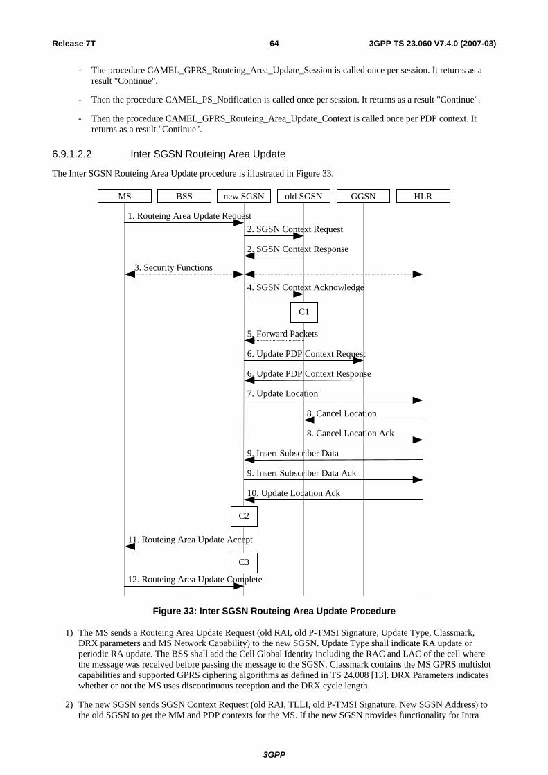
Release 7T 64 3GPP TS 23.060 V7.4.0 (2007-03)
- The procedure CAMEL_GPRS_Routeing_Area_Update_Session is called once per session. It returns as a result "Continue".
- Then the procedure CAMEL_PS_Notification is called once per session. It returns as a result "Continue".
- Then the procedure CAMEL_GPRS_Routeing_Area_Update_Context is called once per PDP context. It returns as a result "Continue".
6.9.1.2.2 Inter SGSN Routeing Area Update
The Inter SGSN Routeing Area Update procedure is illustrated in Figure 33.
MS BSS new SGSN HLR GGSN old SGSN
2. SGSN Context Response
3. Security Functions
1. Routeing Area Update Request 2. SGSN Context Request
6. Update PDP Context Request
6. Update PDP Context Response
7. Update Location
10. Update Location Ack
11. Routeing Area Update Accept
8. Cancel Location
8. Cancel Location Ack
9. Insert Subscriber Data Ack
9. Insert Subscriber Data
12. Routeing Area Update Complete
5. Forward Packets
4. SGSN Context Acknowledge
C3
C2
C1
Figure 33: Inter SGSN Routeing Area Update Procedure
1) The MS sends a Routeing Area Update Request (old RAI, old P-TMSI Signature, Update Type, Classmark, DRX parameters and MS Network Capability) to the new SGSN. Update Type shall indicate RA update or periodic RA update. The BSS shall add the Cell Global Identity including the RAC and LAC of the cell where the message was received before passing the message to the SGSN. Classmark contains the MS GPRS multislot capabilities and supported GPRS ciphering algorithms as defined in TS 24.008 [13]. DRX Parameters indicates whether or not the MS uses discontinuous reception and the DRX cycle length.
2) The new SGSN sends SGSN Context Request (old RAI, TLLI, old P-TMSI Signature, New SGSN Address) to the old SGSN to get the MM and PDP contexts for the MS. If the new SGSN provides functionality for Intra
3GPP

Release 7T 65 3GPP TS 23.060 V7.4.0 (2007-03)
Domain Connection of RAN Nodes to Multiple CN Nodes, the new SGSN may derive the old SGSN from the old RAI and the old P-TMSI (or TLLI) and send the SGSN Context Request message to this old SGSN. Otherwise, the new SGSN derives the old SGSN from the old RAI. In any case the new SGSN will derive an SGSN that it believes is the old SGSN. This derived SGSN is itself the old SGSN, or it is associated with the same pool area as the actual old SGSN and it will determine the correct old SGSN from the P-TMSI (or TLLI) and relay the message to that actual old SGSN. The old SGSN validates the old P-TMSI Signature and responds with an appropriate error cause if it does not match the value stored in the old SGSN. This should initiate the security functions in the new SGSN. If the security functions authenticate the MS correctly, the new SGSN shall send an SGSN Context Request (old RAI, TLLI, MS Validated, New SGSN Address) message to the old SGSN. MS Validated indicates that the new SGSN has authenticated the MS. If the old P-TMSI Signature was valid or if the new SGSN indicates that it has authenticated the MS, the old SGSN stops assigning SNDCP N-PDU numbers to downlink N-PDUs received, and responds with SGSN Context Response (MM Context, PDP Contexts). If the MS is not known in the old SGSN, the old SGSN responds with an appropriate error cause. The old SGSN stores New SGSN Address, to allow the old SGSN to forward data packets to the new SGSN. Each PDP Context includes the SNDCP Send N-PDU Number for the next downlink N-PDU to be sent in acknowledged mode to the MS, the SNDCP Receive N-PDU Number for the next uplink N-PDU to be received in acknowledged mode from the MS, the GTP sequence number for the next downlink N-PDU to be sent to the MS and the GTP sequence number for the next uplink N-PDU to be tunnelled to the GGSN. The old SGSN starts a timer and stops the transmission of N-PDUs to the MS. The new SGSN shall ignore the MS Network Capability contained in MM Context of SGSN Context Response only when it has previously received an MS Network Capability in the Routeing Area Request.
3) Security functions may be executed. These procedures are defined in clause "Security Function". Ciphering mode shall be set if ciphering is supported. If the SGSN Context Response message did not include IMEISV and ADD is supported by the SGSN, the SGSN retrieves the IMEISV from the MS.
If the security functions fail (e.g. because the SGSN cannot determine the HLR address to establish the Send Authentication Info dialogue), the Inter SGSN RAU Update procedure fails. A reject shall be returned to the MS with an appropriate cause.
4) The new SGSN sends an SGSN Context Acknowledge message to the old SGSN. This informs the old SGSN that the new SGSN is ready to receive data packets belonging to the activated PDP contexts. The old SGSN marks in its context that the MSC/VLR association and the information in the GGSNs and the HLR are invalid. This triggers the MSC/VLR, the GGSNs, and the HLR to be updated if the MS initiates a routeing area update procedure back to the old SGSN before completing the ongoing routeing area update procedure. If the security functions do not authenticate the MS correctly, then the routeing area update shall be rejected, and the new SGSN shall send a reject indication to the old SGSN. The old SGSN shall continue as if the SGSN Context Request was never received.
5) The old SGSN duplicates the buffered N-PDUs and starts tunnelling them to the new SGSN. Additional N-PDUs received from the GGSN before the timer described in step 2 expires are also duplicated and tunnelled to the new SGSN. N-PDUs that were already sent to the MS in acknowledged mode and that are not yet acknowledged by the MS are tunnelled together with the SNDCP N-PDU number. No N-PDUs shall be forwarded to the new SGSN after expiry of the timer described in step 2.
6) The new SGSN sends Update PDP Context Request (new SGSN Address, TEID, QoS Negotiated, serving network identity, CGI/SAI, RAT type, CGI/SAI/RAI change support indication, NRSN) to the GGSNs concerned. The SGSN shall send the serving network identity to the GGSN. NRSN indicates SGSN support of the network requested bearer control. The GGSNs update their PDP context fields and return Update PDP Context Response (TEID, Prohibit Payload Compression, APN Restriction, CGI/SAI/RAI change report required, BCM). The Prohibit Payload Compression indicates that the SGSN should negotiate no data compression for this PDP context.
7) The new SGSN informs the HLR of the change of SGSN by sending Update Location (SGSN Number, SGSN Address, IMSI, IMEISV) to the HLR. IMEISV is sent if the ADD function is supported.
8) The HLR sends Cancel Location (IMSI, Cancellation Type) to the old SGSN with Cancellation Type set to Update Procedure. If the timer described in step 2 is not running, the old SGSN removes the MM and PDP contexts. Otherwise, the contexts are removed only when the timer expires. This allows the old SGSN to complete the forwarding of N-PDUs. It also ensures that the MM and PDP contexts are kept in the old SGSN in case the MS initiates another inter-SGSN routeing area update before completing the ongoing routeing area update to the new SGSN. The old SGSN acknowledges with Cancel Location Ack (IMSI).
3GPP

Release 7T 66 3GPP TS 23.060 V7.4.0 (2007-03)
9) The HLR sends Insert Subscriber Data (IMSI, GPRS Subscription Data) to the new SGSN. The new SGSN validates the MS's presence in the (new) RA. If due to regional subscription restrictions or access restrictions the MS is not allowed to be attached in the RA, the SGSN rejects the Routeing Area Update Request with an appropriate cause, and may return an Insert Subscriber Data Ack (IMSI, SGSN Area Restricted) message to the HLR. If all checks are successful, the SGSN constructs an MM context for the MS and returns an Insert Subscriber Data Ack (IMSI) message to the HLR.
10) The HLR acknowledges the Update Location by sending Update Location Ack (IMSI) to the new SGSN.
11) The new SGSN validates the MS's presence in the new RA. If due to roaming restrictions or access restrictions the MS, is not allowed to be attached in the SGSN, or if subscription checking fails, the new SGSN rejects the routeing area update with an appropriate cause. If all checks are successful, the new SGSN constructs MM and PDP contexts for the MS. A logical link is established between the new SGSN and the MS. The new SGSN responds to the MS with Routeing Area Update Accept (P-TMSI, P-TMSI Signature, Receive N-PDU Number). Receive N-PDU Number contains the acknowledgements for each acknowledged-mode NSAPI used by the MS, thereby confirming all mobile-originated N-PDUs successfully transferred before the start of the update procedure.
12) The MS acknowledges the new P-TMSI by returning a Routeing Area Update Complete (Receive N-PDU Number) message to the SGSN. Receive N-PDU Number contains the acknowledgements for each acknowledged-mode NSAPI used by the MS, thereby confirming all mobile-terminated N-PDUs successfully transferred before the start of the update procedure. If Receive N-PDU Number confirms reception of N-PDUs that were forwarded from the old SGSN, these N-PDUs shall be discarded by the new SGSN. LLC and SNDCP in the MS are reset.
In the case of a rejected routeing area update operation, due to regional subscription, roaming restrictions, access restrictions (see TS 23.221 [80] and TS 23.008 [79]) or because the SGSN cannot determine the HLR address to establish the locating updating dialogue, the new SGSN shall not construct an MM context. A reject shall be returned to the MS with an appropriate cause. The MS does not re-attempt a routeing area update to that RA. The RAI value shall be deleted when the MS is powered-up.
If the new SGSN is unable to update the PDP context in one or more GGSNs, the new SGSN shall deactivate the corresponding PDP contexts as described in clause "SGSN-initiated PDP Context Deactivation Procedure". This shall not cause the SGSN to reject the routeing area update.
The PDP Contexts shall be sent from old to new SGSN in a prioritized order, i.e. the most important PDP Context first in the SGSN Context Response message. (The prioritization method is implementation dependent, but should be based on the current activity).
The new SGSN shall determine the Maximum APN restriction based on the received APN Restriction of each PDP context from the GGSN and then store the new Maximum APN restriction value.
If the new SGSN is unable to support the same number of active PDP contexts as received from old SGSN, the new SGSN should use the prioritisation sent by old SGSN as input when deciding which PDP contexts to maintain active and which ones to delete. In any case, the new SGSN shall first update all contexts in one or more GGSNs and then deactivate the context(s) that it cannot maintain as described in subclause "SGSN-initiated PDP Context Deactivation Procedure". This shall not cause the SGSN to reject the routeing area update.
If the timer described in step 2 expires and no Cancel Location (IMSI) was received from the HLR, the old SGSN stops forwarding N-PDUs to the new SGSN.
If the routeing area update procedure fails a maximum allowable number of times, or if the SGSN returns a Routeing Area Update Reject (Cause) message, the MS shall enter IDLE state.
The CAMEL procedure calls shall be performed, see referenced procedures in TS 23.078 [8b]:
C1) CAMEL_GPRS_PDP_Context_Disconnection, CAMEL_GPRS_Detach and CAMEL_PS_Notification.
They are called in the following order:
- The CAMEL_GPRS_PDP_Context_Disconnection procedure is called several times: once per PDP context. The procedure returns as result "Continue".
- Then the CAMEL_GPRS_Detach procedure is called once. The procedure returns as result "Continue".
3GPP

Release 7T 67 3GPP TS 23.060 V7.4.0 (2007-03)
- Then the CAMEL_PS_Notification procedure is called once. The procedure return as result "Continue".
C2) CAMEL_GPRS_Routeing_Area_Update_Session and CAMEL_PS_Notification.
They are called in the following order:
- The CAMEL_GPRS_Routeing_Area_Update_Session procedure is called. The procedure returns as result "Continue".
- Then the CAMEL_PS_Notification procedure is called. The procedure returns as result "Continue".
C3) CAMEL_GPRS_Routeing_Area_Update_Context.
This procedure is called several times: once per PDP context. It returns as result "Continue".
6.9.1.3 Combined RA / LA Update Procedure
A combined RA / LA update takes place in network operation mode I when the MS enters a new RA or when a GPRS-attached MS performs an IMSI attach or when the MS has to indicate new access capabilities to the network, or when a suspended MS is not resumed by the BSS (see subclause "Suspension of GPRS Services"). The MS sends a Routeing Area Update Request indicating that an LA update may also need to be performed, in which case the SGSN forwards the LA update to the VLR. This concerns only idle mode (see TS 23.122 [7b]), as no combined RA / LA updates are performed during a CS connection.
6.9.1.3.1 Combined Intra SGSN RA / LA Update
The Combined RA / LA Update (intra SGSN) procedure is illustrated in Figure 34.
4b. Cancel Location
4c. Cancel Location Ack
4e. Insert Subscriber Data Ack
4d. Insert Subscriber Data
HLRMS BSSnew
MSC/VLRSGSNold
MSC/VLR
3. Location Update Request
1. Routeing Area Update Request
2. Security Functions
4a. Update Location
4f. Update Location Ack
8. TMSI Reallocation Complete
6. Routeing Area Update Accept
5. Location Update Accept
7. Routeing Area Update Complete
C1
Figure 34: Combined RA / LA Update in the Case of Intra SGSN RA Update Procedure
3GPP

Release 7T 68 3GPP TS 23.060 V7.4.0 (2007-03)
1) The MS sends a Routeing Area Update Request (old RAI, old P-TMSI Signature, Update Type) to the SGSN. Update Type shall indicate combined RA / LA update, or, if the MS wants to perform an IMSI attach, combined RA / LA update with IMSI attach requested. The BSS shall add the Cell Global Identity including the RAC and LAC of the cell where the message was received before passing the message to the SGSN.
2) Security functions may be executed. This procedure is defined in clause "Security Function". If the security functions fail (e.g. because the SGSN cannot determine the HLR address to establish the Send Authentication Info dialogue), the Inter SGSN RAU Update procedure fails. A reject shall be returned to the MS with an appropriate cause.
3) If the association has to be established, if Update Type indicates combined RA / LA update with IMSI attach requested, or if the LA changed with the routeing area update, the SGSN sends a Location Update Request (new LAI, IMSI, SGSN Number, Location Update Type) to the VLR. Location Update Type shall indicate IMSI attach if Update Type in step 1 indicated combined RA / LA update with IMSI attach requested. Otherwise, Location Update Type shall indicate normal location update. When the SGSN does not provide functionality for the Intra Domain Connection of RAN Nodes to Multiple CN Nodes, the VLR number is derived from the RAI. When the SGSN provides functionality for Intra Domain Connection of RAN Nodes to Multiple CN Nodes, the SGSN uses the RAI and a hash value from the IMSI to determine the VLR number. The VLR creates or updates the association with the SGSN by storing SGSN Number.
4) If the subscriber data in the VLR is marked as not confirmed by the HLR, the new VLR informs the HLR. The HLR cancels the data in the old VLR and inserts subscriber data in the new VLR:
a) The new VLR sends an Update Location (new VLR) to the HLR.
b) The HLR cancels the data in the old VLR by sending Cancel Location (IMSI) to the old VLR.
c) The old VLR acknowledges with Cancel Location Ack (IMSI).
d) The HLR sends Insert Subscriber Data (IMSI, subscriber data) to the new VLR.
e) The new VLR acknowledges with Insert Subscriber Data Ack (IMSI).
f) The HLR responds with Update Location Ack (IMSI) to the new VLR.
5) The new VLR allocates a new VLR TMSI and responds with Location Update Accept (VLR TMSI) to the SGSN. VLR TMSI is optional if the VLR has not changed.
6) The SGSN validates the MS's presence in the new RA. If due to regional subscription restrictions the MS is not allowed to be attached in the RA, or if subscription checking fails, the SGSN rejects the routeing area update with an appropriate cause. If all checks are successful, the SGSN updates the MM context for the MS. A new P-TMSI may be allocated. The SGSN responds to the MS with Routeing Area Update Accept (P-TMSI, VLR TMSI, P-TMSI Signature).
7) If a new P-TMSI or VLR TMSI was received, the MS confirms the reallocation of the TMSIs by returning a Routeing Area Update Complete message to the SGSN.
8) The SGSN sends a TMSI Reallocation Complete message to the VLR if the MS confirms the VLR TMSI.
If the routeing area update procedure fails a maximum allowable number of times, or if the SGSN returns a Routeing Area Update Reject (Cause) message, the MS shall enter IDLE state.
If the Location Update Accept message indicates a reject, this should be indicated to the MS, and the MS shall not access non-GPRS services until a successful Location Update is performed.
The CAMEL procedure calls shall be performed, see referenced procedures in TS 23.078 [8b]:
C1) CAMEL_GPRS_Routeing_Area_Update_Session, CAMEL_PS_Notification and CAMEL_GPRS_Routeing_Area_Update_Context.
They are called in the following order:
- The procedure CAMEL_GPRS_Routeing_Area_Update_Session is called once per session. In Figure 34, the procedure returns as result "Continue".
- Then the procedure CAMEL_PS_Notification is called. The procedure returns as result "Continue".
3GPP

Release 7T 69 3GPP TS 23.060 V7.4.0 (2007-03)
- Then the procedure CAMEL_GPRS_Routeing_Area_Update_Context is called once per PDP context. In Figure 34, the procedure returns as result "Continue".
6.9.1.3.2 Combined Inter SGSN RA / LA Update
The Combined RA / LA Update (inter-SGSN) procedure is illustrated in Figure 35.
12b. Cancel Location
12c. Cancel Location Ack 12d. Insert Subscriber Data
16. TMSI Reallocation Complete
12f. Update Location Ack 13. Location Update Accept
15. Routeing Area Update Complete
14. Routeing Area Update Accept
8. Cancel Location
8. Cancel Location Ack
6. Update PDP Context Response
6. Update PDP Context Request
7. Update Location
10. Update Location Ack
12a. Update Location 11. Location Update Request
2. SGSN Context Response 3. Security Functions
2. SGSN Context Request 1. Routeing Area Update Request
9. Insert Subscriber Data
9. Insert Subscriber Data Ack
12e. Insert Subscriber Data Ack
MS BSS GGSN old SGSN new SGSN HLR new
MSC/VLR old
MSC/VLR
5. Forward Packets
4. SGSN Context Acknowledge
C3
C2
C1
Figure 35: Combined RA / LA Update in the Case of Inter SGSN RA Update Procedure
3GPP

Release 7T 70 3GPP TS 23.060 V7.4.0 (2007-03)
1) The MS sends a Routeing Area Update Request (old RAI, old P-TMSI Signature, Update Type, Classmark, DRX parameters and MS Network Capability) to the new SGSN. Update Type shall indicate combined RA / LA update, or, if the MS wants to perform an IMSI attach, combined RA / LA update with IMSI attach requested. The BSS shall add the Cell Global Identity including the RAC and LAC of the cell where the message was received before passing the message to the SGSN. Classmark contains the MS GPRS multislot capabilities and supported GPRS ciphering algorithms as defined in TS 24.008 [13]. DRX Parameters indicates whether or not the MS uses discontinuous and the DRX cycle length.
2) The new SGSN sends SGSN Context Request (old RAI, TLLI, old P-TMSI Signature, New SGSN Address) to the old SGSN to get the MM and PDP contexts for the MS. If the new SGSN provides functionality for Intra Domain Connection of RAN Nodes to Multiple CN Nodes, the new SGSN may derive the old SGSN from the old RAI and the old P-TMSI (or TLLI) and send the SGSN Context Request message to this old SGSN. Otherwise, the new SGSN derives the old SGSN from the old RAI. In any case the new SGSN will derive an SGSN that it believes is the old SGSN. This derived SGSN is itself the old SGSN, or it is associated with the same pool area as the actual old SGSN and it will determine the correct old SGSN from the P-TMSI (or TLLI) and relay the message to that actual old SGSN. The old SGSN validates the old P-TMSI Signature and responds with an appropriate error cause if it does not match the value stored in the old SGSN. This should initiate the security functions in the new SGSN. If the security functions authenticate the MS correctly, the new SGSN shall send an SGSN Context Request (old RAI, TLLI, MS Validated, New SGSN Address) message to the old SGSN. MS Validated indicates that the new SGSN has authenticated the MS. If the old P-TMSI Signature was valid or if the new SGSN indicates that it has authenticated the MS, the old SGSN stops assigning SNDCP N-PDU numbers to downlink N-PDUs received, and responds with SGSN Context Response (MM Context, PDP Contexts). If the MS is not known in the old SGSN, the old SGSN responds with an appropriate error cause. The old SGSN stores New SGSN Address until the old MM context is cancelled, to allow the old SGSN to forward data packets to the new SGSN. Each PDP Context includes the SNDCP Send N-PDU Number for the next downlink N-PDU to be sent in acknowledged mode to the MS, the SNDCP Receive N-PDU Number for the next uplink N-PDU to be received in acknowledged mode from the MS, the GTP sequence number for the next downlink N-PDU to be sent to the MS and the GTP sequence number for the next uplink N-PDU to be tunnelled to the GGSN. The old SGSN starts a timer and stops the downlink transfer. The new SGSN shall ignore the MS Network Capability contained in MM Context of SGSN Context Response only when it has previously received an MS Network Capability in the Routeing Area Request.
3) Security functions may be executed. These procedures are defined in clause "Security Function". Ciphering mode shall be set if ciphering is supported. If the SGSN Context Response message did not include IMEISV and ADD is supported, the SGSN retrieves the IMEISV from the MS. If the security functions fail (e.g. because the SGSN cannot determine the HLR address to establish the Send Authentication Info dialogue), the Inter SGSN RAU Update procedure fails. A reject shall be returned to the MS with an appropriate cause.
4) The new SGSN sends an SGSN Context Acknowledge message to the old SGSN. This informs the old SGSN that the new SGSN is ready to receive data packets belonging to the activated PDP contexts. The old SGSN marks in its context that the MSC/VLR association and the information in the GGSNs and the HLR are invalid. This triggers the MSC/VLR, the GGSNs, and the HLR to be updated if the MS initiates a routeing area update procedure back to the old SGSN before completing the ongoing routeing area update procedure. If the security functions do not authenticate the MS correctly, the routeing area update shall be rejected, and the new SGSN shall send a reject indication to the old SGSN. The old SGSN shall continue as if the SGSN Context Request was never received.
5) The old SGSN duplicates the buffered N-PDUs and starts tunnelling them to the new SGSN. Additional N-PDUs received from the GGSN before the timer described in step 2 expires are also duplicated and tunnelled to the new SGSN. N-PDUs that were already sent to the MS in acknowledged mode and that are not yet acknowledged by the MS are tunnelled together with the SNDCP N-PDU number. No N-PDUs shall be forwarded to the new SGSN after expiry of the timer described in step 2.
6) The new SGSN sends Update PDP Context Request (new SGSN Address, TEID, QoS Negotiated, serving network identity, CGI/SAI, RAT type, CGI/SAI/RAI change support indication, NRSN) to the GGSNs concerned. The SGSN shall send the serving network identity to the GGSN. NRSN indicates SGSN support of the network requested bearer control. The GGSNs update their PDP context fields and return an Update PDP Context Response (TEID, Prohibit Payload Compression, APN Restriction, CGI/SAI/RAI change report required, BCM). The Prohibit Payload Compression indicates that the SGSN should negotiate no data compression for this PDP context.
7) The new SGSN informs the HLR of the change of SGSN by sending Update Location (SGSN Number, SGSN Address, IMSI, IMEISV) to the HLR. IMEISV is sent if the ADD function is supported.
3GPP
Release 7T 71 3GPP TS 23.060 V7.4.0 (2007-03)
8) The HLR sends Cancel Location (IMSI, Cancellation Type) to the old SGSN with Cancellation Type set to Update Procedure. If the timer described in step 2 is not running, the old SGSN removes the MM and PDP contexts. Otherwise, the contexts are removed only when the timer expires. This allows the old SGSN to complete the forwarding of N-PDUs. It also ensures that the MM and PDP contexts are kept in the old SGSN in case the MS initiates another inter SGSN routeing area update before completing the ongoing routeing area update to the new SGSN. The old SGSN acknowledges with Cancel Location Ack (IMSI).
9) The HLR sends Insert Subscriber Data (IMSI, GPRS Subscription Data) to the new SGSN. The new SGSN validates the MS's presence in the (new) RA. If due to regional subscription restrictions or access restrictions the MS is not allowed to be attached in the RA, the SGSN rejects the Routeing Area Update Request with an appropriate cause, and may return an Insert Subscriber Data Ack (IMSI, SGSN Area Restricted) message to the HLR. If all checks are successful, the SGSN constructs an MM context for the MS and returns an Insert Subscriber Data Ack (IMSI) message to the HLR.
10) The HLR acknowledges the Update Location by sending Update Location Ack (IMSI) to the new SGSN.
11) If the association has to be established, if Update Type indicates combined RA / LA update with IMSI attach requested, or if the LA changed with the routeing area update, the new SGSN sends a Location Update Request (new LAI, IMSI, SGSN Number, Location Update Type) to the VLR. Location Update Type shall indicate IMSI attach if Update Type in step 1 indicated combined RA / LA update with IMSI attach requested. Otherwise, Location Update Type shall indicate normal location update. When the SGSN does not provide functionality for the Intra Domain Connection of RAN Nodes to Multiple CN Nodes, the VLR number is derived from the RAI. When the SGSN provides functionality for Intra Domain Connection of RAN Nodes to Multiple CN Nodes, the SGSN uses the RAI and a hash value from the IMSI to determine the VLR number. The SGSN starts the location update procedure towards the new MSC/VLR upon receipt of the first Insert Subscriber Data message from the HLR in step 9). The VLR creates or updates the association with the SGSN by storing SGSN Number.
12) If the subscriber data in the VLR is marked as not confirmed by the HLR, the new VLR informs the HLR. The HLR cancels the old VLR and inserts subscriber data in the new VLR:
a) The new VLR sends an Update Location (new VLR) to the HLR.
b) The HLR cancels the data in the old VLR by sending Cancel Location (IMSI) to the old VLR.
c) The old VLR acknowledges with Cancel Location Ack (IMSI).
d) The HLR sends Insert Subscriber Data (IMSI, subscriber data) to the new VLR.
e) The new VLR acknowledges with Insert Subscriber Data Ack (IMSI).
f) The HLR responds with Update Location Ack (IMSI) to the new VLR.
13) The new VLR allocates a new TMSI and responds with Location Update Accept (VLR TMSI) to the SGSN. VLR TMSI is optional if the VLR has not changed.
14) The new SGSN validates the MS's presence in the new RA. If due to roaming restrictions or access restrictions the MS is not allowed to be attached in the RA, or if subscription checking fails, the SGSN rejects the routeing area update with an appropriate cause. If all checks are successful, the new SGSN establishes MM and PDP contexts for the MS. A logical link is established between the new SGSN and the MS. The new SGSN responds to the MS with Routeing Area Update Accept (P-TMSI, VLR TMSI, P-TMSI Signature, Receive N-PDU Number). Receive N-PDU Number contains the acknowledgements for each acknowledged-mode NSAPI used by the MS, thereby confirming all mobile-originated N-PDUs successfully transferred before the start of the update procedure.
15) The MS confirms the reallocation of the TMSIs by returning a Routeing Area Update Complete (Receive N-PDU Number) message to the SGSN. Receive N-PDU Number contains the acknowledgements for each acknowledged-mode NSAPI used by the MS, thereby confirming all mobile-terminated N-PDUs successfully transferred before the start of the update procedure. If Receive N-PDU Number confirms reception of N-PDUs that were forwarded from the old SGSN, these N-PDUs shall be discarded by the new SGSN. LLC and SNDCP in the MS are reset.
16) The new SGSN sends a TMSI Reallocation Complete message to the new VLR if the MS confirms the VLR TMSI.
3GPP

Release 7T 72 3GPP TS 23.060 V7.4.0 (2007-03)
In the case of a rejected routeing area update operation, due to regional subscription, roaming restrictions, access restrictions (see TS 23.221 [80] and TS 23.008 [79]) or because the SGSN cannot determine the HLR address to establish the locating updating dialogue, the new SGSN shall not construct an MM context. A reject shall be returned to the MS with an appropriate cause. The MS shall not re-attempt a routeing area update to that RA. The RAI value shall be deleted when the MS is powered-up.
If the new SGSN is unable to update the PDP context in one or more GGSNs, the new SGSN shall deactivate the corresponding PDP contexts as described in clause "SGSN-initiated PDP Context Deactivation Procedure". This shall not cause the SGSN to reject the routeing area update.
The PDP Contexts shall be sent from old to new SGSN in a prioritized order, i.e. the most important PDP Context first in the SGSN Context Response message. (The prioritization method is implementation dependent, but should be based on the current activity).
The new SGSN shall determine the Maximum APN restriction based on the received APN Restriction of each PDP context from the GGSN and then store the new Maximum APN restriction value.
If the new SGSN is unable to support the same number of active PDP contexts as received from old SGSN, the new SGSN should use the prioritisation sent by old SGSN as input when deciding which PDP contexts to maintain active and which ones to delete. In any case, the new SGSN shall first update all contexts in one or more GGSNs and then deactivate the context(s) that it cannot maintain as described in subclause "SGSN-initiated PDP Context Deactivation Procedure". This shall not cause the SGSN to reject the routeing area update.
If the routeing area update procedure fails a maximum allowable number of times, or if the SGSN returns a Routeing Area Update Reject (Cause) message, the MS shall enter IDLE state.
If the timer described in step 2 expires and no Cancel Location (IMSI) was received from the HLR, the old SGSN shall stop forwarding N-PDUs to the new SGSN.
If the Location Update Accept message indicates a reject, this should be indicated to the MS, and the MS shall not access non-GPRS services until a successful location update is performed.
The CAMEL procedure calls shall be performed, see referenced procedures in TS 23.078 [8b]:
C1) CAMEL_GPRS_PDP_Context_Disconnection, CAMEL_GPRS_Detach and CAMEL_PS_Notification.
They are called in the following order:
- The CAMEL_GPRS_PDP_Context_Disconnection procedure is called several times: once per PDP context. The procedure returns as result "Continue".
- Then the CAMEL_GPRS_Detach procedure is called once. The procedure returns as result "Continue".
- Then the CAMEL_PS_Notification procedure is called once. The procedure returns as result "Continue".
C2) CAMEL_GPRS_Routeing_Area_Update_Session and CAMEL_PS_Notification.
They are called in the following order:
- The CAMEL_GPRS_Routeing_Area_Update_Session procedure is called. The procedure returns as result "Continue".
- Then the CAMEL_PS_Notification procedure is called. The procedure returns as result "Continue".
C3) CAMEL_GPRS_Routeing_Area_Update_Context.
This procedure is called several times: once per PDP context. It returns as result "Continue".
6.9.2 Location Management Procedures (Iu-mode) In the context of this specification, the terms RNS or RNC refer also to a GERAN BSS or BSC (respectively) when serving an MS in Iu mode.
Refer to TS 25.301 [50] for further information on the location management procedures for the UTRAN.
3GPP

Release 7T 73 3GPP TS 23.060 V7.4.0 (2007-03)
The PLMN shall provide information for the MS to be able to:
- detect when it has entered a new cell or a new RA; and
- determine when to perform periodic RA updates.
In this specification, only the Location Management procedures related to the CN are described. These procedures are:
- a routeing area update procedure; and
- Serving RNC relocation procedure.
An MS detects entering a new cell by comparing the cell's identity with the cell identity stored in the MS. By comparing the RAI stored in the MS's MM context with the RAI received from the network, the MS detects that an RA update shall be performed. In RRC-CONNECTED mode (PMM-CONNECTED state or CS MM CONNECTED state), the MS is informed of RAI and Cell Identity by the serving RNC via an "MM information" message at the RRC layer. In RRC-IDLE state, the MS is informed of RAI and Cell Identity by the broadcast system information at the RRC layer.
If the MS enters a new PLMN, the MS shall perform a routeing area update, unless it is not allowed to do so for the reasons specified in TS 24.008 [13] and TS 23.122 [7b].
In network mode of operation II, whenever an MS determines that it shall perform both an LA update and an RA update, the MS shall start the LA update first. The MS should start the RA update procedure before the LA update is completed.
6.9.2.1 Routeing Area Update Procedure
A routeing area update takes place when an attached MS detects that it has entered a new RA or when the periodic RA update timer has expired or when RRC connection is released with cause "Directed Signalling connection re-establishment" or when the MS has to indicate new access capabilities to the network.
The SGSN detects that it is an intra-SGSN routeing area update by noticing that it also handles the old RA. In this case, the SGSN has the necessary information about the MS and there is no need to inform the GGSNs or the HLR about the new MS location. A periodic RA update is always an intra-SGSN routeing area update. If the network operates in mode I, an MS that is in CS/PS mode of operation shall perform the Combined RA / LA Update procedures except this CS/PS mode MS is engaged in a CS connection, then it shall perform (non combined) RA Update procedures.
In Iu mode, an RA update is either an intra-SGSN or inter-SGSN RA update, either combined RA / LA update or only RA update, either initiated by an MS in PMM-CONNECTED or in PMM-IDLE state. The SRNC may provide a PMM-CONNECTED state MS with MM information like RAI by dedicated signalling. Typically, the SRNC should not provide a RAI to an MS in PMM-CONNECTED state. An exception is after an SRNS relocation, in which case the new SRNC shall indicate the RAI to the MS.
During the Routeing Area Update procedure, the MS provides its PS Handover capabilities as defined in TS 24.008 [13].
All the RA update cases are contained in the procedure illustrated in Figure 36.
NOTE 1: The network may receive an RA update from a UE in PMM-CONNECTED state over a new Iu signalling connection. This could happen when the UE enters PMM-IDLE state on receipt of RRC Connection Release with cause "Directed Signalling connection re-establishment" and initiates an RA or Combined RA update procedure (see clause 6.1.2.4.1).
3GPP

Release 7T 74 3GPP TS 23.060 V7.4.0 (2007-03)
3. SGSN Context Response 4. Security Functions
2. SGSN Context Request 1. Routeing Area Update Request
MS old
SRNS GGSN old
3G-SGSNnew
3G-SGSN HLR new
MSC/VLR old
MSC/VLR
5. SGSN Context Ack
11. Cancel Location
11. Cancel Location Ack
9. Update PDP Context Response
9. Update PDP Context Request
10. Update Location
15b. Cancel Location
15c. Cancel Location Ack 15d. Insert Subscriber Data
19. TMSI Reallocation Complete
15f. Update Location Ack 16. Location Update Accept
18. Routeing Area Update Complete
17. Routeing Area Update Accept
13. Update Location Ack
15a. Update Location 14. Location Update Request
12. Insert Subscriber Data
12. Insert Subscriber Data Ack
15e. Insert Subscriber Data Ack
C3
C2
2a. SRNS Context Request
2a. SRNS Context Response
11a. Iu Release Command
11a. Iu Release Complete
6. SRNS Data Forward Command 7. Forward Packets
8. Forward Packets
new SRNS
C1
Figure 36: Iu mode RA Update Procedure
3GPP

Release 7T 75 3GPP TS 23.060 V7.4.0 (2007-03)
1) The RRC connection is established, if not already done. The MS sends a Routeing Area Update Request message (P-TMSI, old RAI, old P-TMSI Signature, Update Type, follow on request, Classmark, DRX Parameters, MS Network Capability) to the new SGSN. The MS shall set a follow-on request if there is pending uplink traffic (signalling or user data). The SGSN may use, as an implementation option, the follow-on request indication to release or keep the Iu connection after the completion of the RA update procedure. Update Type shall indicate:
- RA Update if the RA Update is triggered by a change of RA;
- Periodic RA Update if the RA update is triggered by the expiry of the Periodic RA Update timer;
- Combined RA / LA Update if the MS is also IMSI-attached and the LA update shall be performed in network operation mode I (see clause "Interactions Between SGSN and MSC/VLR"); or
- Combined RA / LA Update with IMSI attach requested if the MS wants to perform an IMSI attach in network operation mode I.
The SRNC shall add the Routeing Area Identity before forwarding the message to the 3G-SGSN. This RA identity corresponds to the RAI in the MM system information sent by the SRNC to the MS. Classmark is described in clause "MS Network Capability". DRX Parameters indicates whether or not the MS uses discontinuous reception and the DRX cycle length.
NOTE 2: Sending the Routeing Area Update Request message to the SGSN triggers the establishment of a signalling connection between RAN and SGSN for the concerned MS.
2) If the RA update is an Inter-SGSN Routeing area update and if the MS was in PMM-IDLE state, the new SGSN sends an SGSN Context Request message (old P-TMSI, old RAI, old P-TMSI Signature) to the old SGSN to get the MM and PDP contexts for the MS. If the new SGSN provides functionality for Intra Domain Connection of RAN Nodes to Multiple CN Nodes, the new SGSN may derive the old SGSN from the old RAI and the old P-TMSI and send the SGSN Context Request message to this old SGSN. Otherwise, the new SGSN derives the old SGSN from the old RAI. In any case the new SGSN will derive an SGSN that it believes is the old SGSN. This derived SGSN is itself the old SGSN, or it is associated with the same pool area as the actual old SGSN and it will determine the correct old SGSN from the P-TMSI and relay the message to that actual old SGSN. The old SGSN validates the old P-TMSI Signature and responds with an appropriate error cause if it does not match the value stored in the old SGSN. This should initiate the security functions in the new SGSN. If the security functions authenticate the MS correctly, the new SGSN shall send an SGSN Context Request (IMSI, old RAI, MS Validated) message to the old SGSN. MS Validated indicates that the new SGSN has authenticated the MS. If the old P-TMSI Signature was valid or if the new SGSN indicates that it has authenticated the MS, the old SGSN starts a timer.. If the MS is not known in the old SGSN, the old SGSN responds with an appropriate error cause.
2a) If the MS is PMM-CONNECTED state in the old 3G-SGSN or, in case of an intra-SGSN RA update, if the MS is in the PMM-CONNECTED state and the RAU was received over another Iu connection than the established one, the old SGSN sends an SRNS Context Request (IMSI) message to the old SRNS to retrieve the sequence numbers for the PDP context for inclusion in the SGSN Context Response message. Upon reception of this message, the SRNS buffers and stops sending downlink PDUs to the MS and returns an SRNS Context Response (IMSI, GTP-SNDs, GTP-SNUs, PDCP-SNUs) message. The SRNS shall include for each PDP context the next in-sequence GTP sequence number to be sent to the MS and the GTP sequence number of the next uplink PDU to be tunnelled to the GGSN. For each active PDP context which uses lossless PDCP, the SRNS also includes the uplink PDCP sequence number (PDCP-SNU). PDCP-SNU shall be the next in-sequence PDCP sequence number expected from the MS (per each active radio bearer). No conversion of PDCP sequence numbers to SNDCP sequence numbers shall be done in the 3G-SGSN.
3) The old 3G-SGSN responds with an SGSN Context Response (MM Context, PDP Contexts) message. For each PDP context the old 3G-SGSN shall include the GTP sequence number for the next uplink GTP PDU to be tunnelled to the GGSN and the next downlink GTP sequence number for the next PDU to be sent to the MS. Each PDP Context also includes the PDCP sequence numbers if PDCP sequence numbers are received from the old SRNS. The new 3G-SGSN shall ignore the MS Network Capability contained in MM Context of SGSN Context Response only when it has previously received an MS Network Capability in the Routeing Area Request. The GTP sequence numbers received from the old 3G-SGSN are only relevant if delivery order is required for the PDP context (QoS profile).
4) Security functions may be executed. These procedures are defined in clause "Security Function". If the SGSN Context Response message did not include IMEISV and ADD is supported, the SGSN retrieves the IMEISV from the MS. If the security functions do not authenticate the MS correctly, the routeing area update shall be
3GPP

Release 7T 76 3GPP TS 23.060 V7.4.0 (2007-03)
rejected, and the new SGSN shall send a reject indication to the old SGSN. The old SGSN shall continue as if the SGSN Context Request was never received.
5) If the RA update is an Inter-SGSN Routeing area update, the new SGSN sends an SGSN Context Acknowledge message to the old SGSN. The old SGSN marks in its context that the MSC/VLR association and the information in the GGSNs and the HLR are invalid. This triggers the MSC/VLR, the GGSNs, and the HLR to be updated if the MS initiates a routeing area update procedure back to the old SGSN before completing the ongoing routeing area update procedure.
6) If the MS is in PMM-CONNECTED state in the old 3G-SGSN or, in case of an intra-SGSN RA update, if the MS is PMM connected and the RAU was received over another Iu connection than the established one, the old 3G-SGSN sends an SRNS Data Forward Command (RAB ID, Transport Layer Address, Iu Transport Association) message to the SRNS. Upon receipt of the SRNS Data Forward Command message from the 3G-SGSN, the SRNS shall start the data-forwarding timer.
7) For each indicated RAB the SRNS starts duplicating and tunnelling the buffered GTP PDUs to the old 3G-SGSN. For each radio bearer which uses lossless PDCP the SRNS shall start tunnelling the partly transmitted and the transmitted but not acknowledged PDCP-PDUs together with their related PDCP sequence numbers and start duplicating and tunnelling the buffered GTP PDUs to the old 3G-SGSN. Upon receipt of the SRNS Data Forward Command message from the 3G-SGSN, the SRNS shall start the data-forwarding timer.
8) If the RA update is an Inter-SGSN RA Update, the old 3G-SGSN tunnels the GTP PDUs to the new 3G-SGSN. No conversion of PDCP sequence numbers to SNDCP sequence numbers shall be done in the 3G-SGSN.
9) If the RA update is an Inter-SGSN RA Update and if the MS was not in PMM-CONNECTED state in the new 3G-SGSN, the new SGSN sends Update PDP Context Request (new SGSN Address, QoS Negotiated, Tunnel Endpoint Identifier, serving network identity, CGI/SAI, RAT type, CGI/SAI/RAI change support indication, NRSN) to the GGSNs concerned. The SGSN shall send the serving network identity to the GGSN. NRSN indicates SGSN support of the network requested bearer control. The GGSNs update their PDP context fields and return an Update PDP Context Response (Tunnel Endpoint Identifier, Prohibit Payload Compression, APN Restriction, CGI/SAI/RAI change report required, BCM). The Prohibit Payload Compression indicates that the SGSN should negotiate no data compression for this PDP context. Note: If the RA update is an Inter-SGSN routeing area update initiated by an MS in PMM-CONNECTED state in the new 3G-SGSN, the Update PDP Context Request message is sent as described in subclause "Serving RNS Relocation Procedures".
10) If the RA update is an Inter-SGSN RA Update, the new SGSN informs the HLR of the change of SGSN by sending Update Location (SGSN Number, SGSN Address, IMSI, IMEISV) to the HLR. IMEISV is sent if the ADD function is supported.
11) If the RA update is an Inter-SGSN RA Update, the HLR sends Cancel Location (IMSI, Cancellation Type) to the old SGSN with Cancellation Type set to Update Procedure. If the timer described in step 2 is not running, the old SGSN removes the MM context. Otherwise, the contexts are removed only when the timer expires. It also ensures that the MM context is kept in the old SGSN in case the MS initiates another inter SGSN routeing area update before completing the ongoing routeing area update to the new SGSN. The old SGSN acknowledges with Cancel Location Ack (IMSI).
11a) On receipt of Cancel Location, if the MS is PMM-CONNECTED in the old 3G-SGSN, the old 3G-SGSN sends an Iu Release Command message to the old SRNC. When the data-forwarding timer has expired, the SRNS responds with an Iu Release Complete message.
12) If the RA update is an inter-SGSN RA Update, the HLR sends Insert Subscriber Data (IMSI, subscription data) to the new SGSN. The new SGSN validates the MS's presence in the (new) RA. If due to regional subscription restrictions or access restrictions the MS is not allowed to be attached in the RA, the SGSN rejects the Routeing Area Update Request with an appropriate cause, and may return an Insert Subscriber Data Ack (IMSI, SGSN Area Restricted) message to the HLR. If the network supports the MOCN configuration for network sharing, the SGSN may, if the MS is not a 'Network Sharing Supporting MS', in this case decide to initiate redirection by sending a Reroute Command to the RNS, as described in TS 23.251 [83] instead of rejecting the Routeing Area Update Request. If all checks are successful, the SGSN constructs an MM context for the MS and returns an Insert Subscriber Data Ack (IMSI) message to the HLR.
13) If the RA update is an Inter-SGSN RA Update, the HLR acknowledges the Update Location by sending Update Location Ack (IMSI) to the new SGSN.
3GPP

Release 7T 77 3GPP TS 23.060 V7.4.0 (2007-03)
14) If Update Type indicates combined RA / LA update with IMSI attach requested, or if the LA changed with the routeing area update, the association has to be established, and the new SGSN sends a Location Update Request (new LAI, IMSI, SGSN Number, Location Update Type) to the VLR. Location Update Type shall indicate IMSI attach if Update Type in step 1 indicated combined RA / LA update with ISI attach requested. Otherwise, Location Update Type shall indicate normal location update. When the SGSN does not provide functionality for the Intra Domain Connection of RAN Nodes to Multiple CN Nodes, the VLR number is derived from the RAI. When the SGSN provides functionality for Intra Domain Connection of RAN Nodes to Multiple CN Nodes, the SGSN uses the RAI and a hash value from the IMSI to determine the VLR number. The SGSN starts the location update procedure towards the new MSC/VLR upon receipt of the first Insert Subscriber Data message from the HLR in step 8). The VLR creates or updates the association with the SGSN by storing SGSN Number. In networks that support network sharing, the Location Update Request includes the identity of the selected core network operator if the SGSN has received this information from the RNS, as described in TS 23.251 [83].
15) If the subscriber data in the VLR is marked as not confirmed by the HLR, the new VLR informs the HLR. The HLR cancels the old VLR and inserts subscriber data in the new VLR:
a) The new VLR sends an Update Location (new VLR) to the HLR.
b) The HLR cancels the data in the old VLR by sending Cancel Location (IMSI) to the old VLR.
c) The old VLR acknowledges with Cancel Location Ack (IMSI).
d) The HLR sends Insert Subscriber Data (IMSI, subscriber data) to the new VLR.
e) The new VLR acknowledges with Insert Subscriber Data Ack (IMSI).
f) The HLR responds with Update Location Ack (IMSI) to the new VLR.
16) The new VLR allocates a new TMSI and responds with Location Update Accept (VLR TMSI) to the SGSN. VLR TMSI is optional if the VLR has not changed.
17) The new SGSN validates the MS's presence in the new RA. If due to roaming restrictions or access restrictions the MS is not allowed to be attached in the RA, or if subscription checking fails, the SGSN rejects the routeing area update with an appropriate cause. If the network supports the MOCN configuration for network sharing, the SGSN may, if the MS is not a 'Network Sharing Supporting MS', in this case decide to initiate redirection by sending a Reroute Command to the RNS, as described in TS 23.251 [83] instead of rejecting the routeing area update. If all checks are successful, the new SGSN establishes MM context for the MS. The new SGSN responds to the MS with Routeing Area Update Accept (P-TMSI, VLR TMSI, P-TMSI Signature).
18) The MS confirms the reallocation of the TMSIs by returning a Routeing Area Update Complete message to the SGSN.
19) The new SGSN sends a TMSI Reallocation Complete message to the new VLR if the MS confirms the VLR TMSI.
NOTE 3: Steps 15, 16, and 19 are performed only if step 14 is performed.
NOTE 4: The new SGSN may initiate RAB establishment after execution of the security functions (step 4), or wait until completion of the RA update procedure. For the MS, RAB establishment may occur anytime after the RA update request is sent (step 1).
In the case of a rejected routeing area update operation, due to regional subscription, roaming restrictions, or access restrictions (see TS 23.221 [80] and TS 23.008 [79]) the new SGSN shall not construct an MM context. A reject shall be returned to the MS with an appropriate cause. The MS shall not re-attempt a routeing area update to that RA. The RAI value shall be deleted when the MS is powered up. If the network supports the MOCN configuration for network sharing, the SGSN may, if the MS is not a 'Network Sharing Supporting MS', in this case decide to initiate redirection by sending a Reroute Command to the RNS, as described in TS 23.251 [83] instead of rejecting the routeing area update.
If the new SGSN is unable to update the PDP context in one or more GGSNs, the new SGSN shall deactivate the corresponding PDP contexts as described in subclause "SGSN-initiated PDP Context Deactivation Procedure". This shall not cause the SGSN to reject the routeing area update.
3GPP

Release 7T 78 3GPP TS 23.060 V7.4.0 (2007-03)
The PDP Contexts shall be sent from old to new SGSN in a prioritized order, i.e. the most important PDP Context first in the SGSN Context Response message. (The prioritization method is implementation dependent, but should be based on the current activity).
The new SGSN shall determine the Maximum APN restriction based on the received APN Restriction of each PDP context from the GGSN and then store the new Maximum APN restriction value.
If the new SGSN is unable to support the same number of active PDP contexts as received from old SGSN, the new SGSN should use the prioritisation sent by old SGSN as input when deciding which PDP contexts to maintain active and which ones to delete. In any case, the new SGSN shall first update all contexts in one or more GGSNs and then deactivate the context(s) that it cannot maintain as described in subclause "SGSN-initiated PDP Context Deactivation Procedure". This shall not cause the SGSN to reject the routeing area update.
NOTE 5: In case MS was in PMM-CONNECTED state the PDP Contexts are sent already in the Forward Relocation Request message as described in subclause "Serving RNS relocation procedures".
If the routeing area update procedure fails a maximum allowable number of times, or if the SGSN returns a Routeing Area Update Reject (Cause) message, the MS shall enter PMM-DETACHED state.
If the Location Update Accept message indicates a reject, this should be indicated to the MS, and the MS shall not access non-PS services until a successful location update is performed.
The CAMEL procedure calls shall be performed, see referenced procedures in TS 23.078 [8b]:
C1) CAMEL_GPRS_PDP_Context_Disconnection, CAMEL_GPRS_Detach and CAMEL_PS_Notification.
They are called in the following order:
- The CAMEL_GPRS_PDP_Context_Disconnection procedure is called several times: once per PDP context. The procedure returns as result "Continue".
- Then the CAMEL_GPRS_Detach procedure is called once. The procedure returns as result "Continue".
- Then the CAMEL_PS_Notification procedure is called once. The procedure returns as result "Continue".
C2) CAMEL_GPRS_Routeing_Area_Update_Session and CAMEL_PS_Notification.
They are called in the following order:
- The CAMEL_GPRS_Routeing_Area_Update_Session procedure is called. The procedure returns as result "Continue".
- Then the CAMEL_PS_Notification procedure is called. The procedure returns as result "Continue".
C3) CAMEL_GPRS_Routeing_Area_Update_Context.
This procedure is called several times: once per PDP context. It returns as result "Continue".
6.9.2.2 Serving RNS Relocation Procedures
In the context of this specification, the terms RNS or RNC refer also to a GERAN BSS or BSC (respectively) when serving an MS in Iu mode.
Serving RNS relocation procedures move the RAN to CN connection point at the RAN side of the source RNC to the target RNC. The Serving RNS Relocation Procedures, described in the following sub-clauses, may be performed as "Lossless SRNS Relocation", which means packet loss during the SRNS change is eliminated. For this purpose, the RNS and the MS have to provide PDCP layer functionality, which in the subsequent description is referred as the lossless PDCP. The source RNC decides to perform the Serving RNS Relocation Procedure as "Lossless SRNS Relocation" based on capabilities of the UE and the RNS and based on QoS parameters (e.g. SDU error ratio).
For "Lossless SRNS Relocation", both the MS and the source RNS have to support and to use the lossless PDCP. When the SRNS changes, the old RNS forwards all received and not yet transferred downlink GTP-PDUs to the target RNS. GTP-PDUs forwarded to the target RNS indicate a PDCP sequence number if the contained N-PDUs were sent to the MS as a PDCP-SDUs, but are not yet acknowledged by lossless PDCP. The target RNS and the MS exchange respective sequence numbers of next expected PDCP-PDUs. This process indicates PDCP-PDUs that were already
3GPP

Release 7T 79 3GPP TS 23.060 V7.4.0 (2007-03)
successfully transferred between the MS and the source RNS for downlink and uplink directions, respectively. This also confirms all N-PDUs (PDCP-SDUs) successfully transferred before the change of the SRNS. These N-PDUs are discarded by the MS and the target RNS, respectively. The target RNS identifies the forwarded GTP-PDUs containing confirmed N-PDUs by the PDCP sequence number in the GTP-PDU. All other N-PDUs have to be transmitted via the new MS – RNS link.
6.9.2.2.1 Serving RNS Relocation Procedure
This procedure is only performed for an MS in PMM-CONNECTED state where the Iur interface carries both the control signalling and the user data. This procedure is not applicable for GERAN.
The Serving SRNS Relocation procedure is used to move the RAN to CN connection point at the RAN side from the source SRNC to the target RNC, from a "standing still position". In the procedure, the Iu links are relocated. If the target RNC is connected to the same SGSN as the source SRNC, an Intra-SGSN SRNS Relocation procedure is performed. If the routeing area is changed, this procedure is followed by an Intra-SGSN Routeing Area Update procedure. The SGSN detects an Intra-SGSN routeing area update by noticing that it also handles the old RA. In this case, the SGSN has the necessary information about the MS and there is no need to inform the HLR about new location of the MS.
Figure 37 shows user data routing before SRNS relocation when source SRNC and target RNC are connected to different SGSNs. Figure 38 shows the user data routing after SRNS Relocation procedure and Routeing Area Update procedure is completed. In case depicted in Figure 37 and Figure 38, the MS is in state PMM-CONNECTED.
LA1, RA1
HLR/AuC
old SGSN
GGSN
LA2, RA2
new SGSN
source SRNC
new MSC/VLRold MSC/VLR
MS
target RNC
Figure 37: Before SRNS Relocation and Routeing Area Update
Before the SRNS Relocation procedure and RA update, the MS is registered in the old SGSN. The source RNC is acting as a serving RNC (SRNC).
3GPP

Release 7T 80 3GPP TS 23.060 V7.4.0 (2007-03)
LA1, RA1
MS
HLR/AuC
old SGSN
source RNC
GGSN
LA2, RA2
new SGSNold MSC/VLR new MSC/VLR
target SRNC
Figure 38: After SRNS Relocation and Routeing Area Update
After the SRNS Relocation procedure and RA update, the MS is registered in the new SGSN. The MS is in the state PMM-CONNECTED towards the new SGSN, and the target RNC is acting as the serving RNC.
3GPP
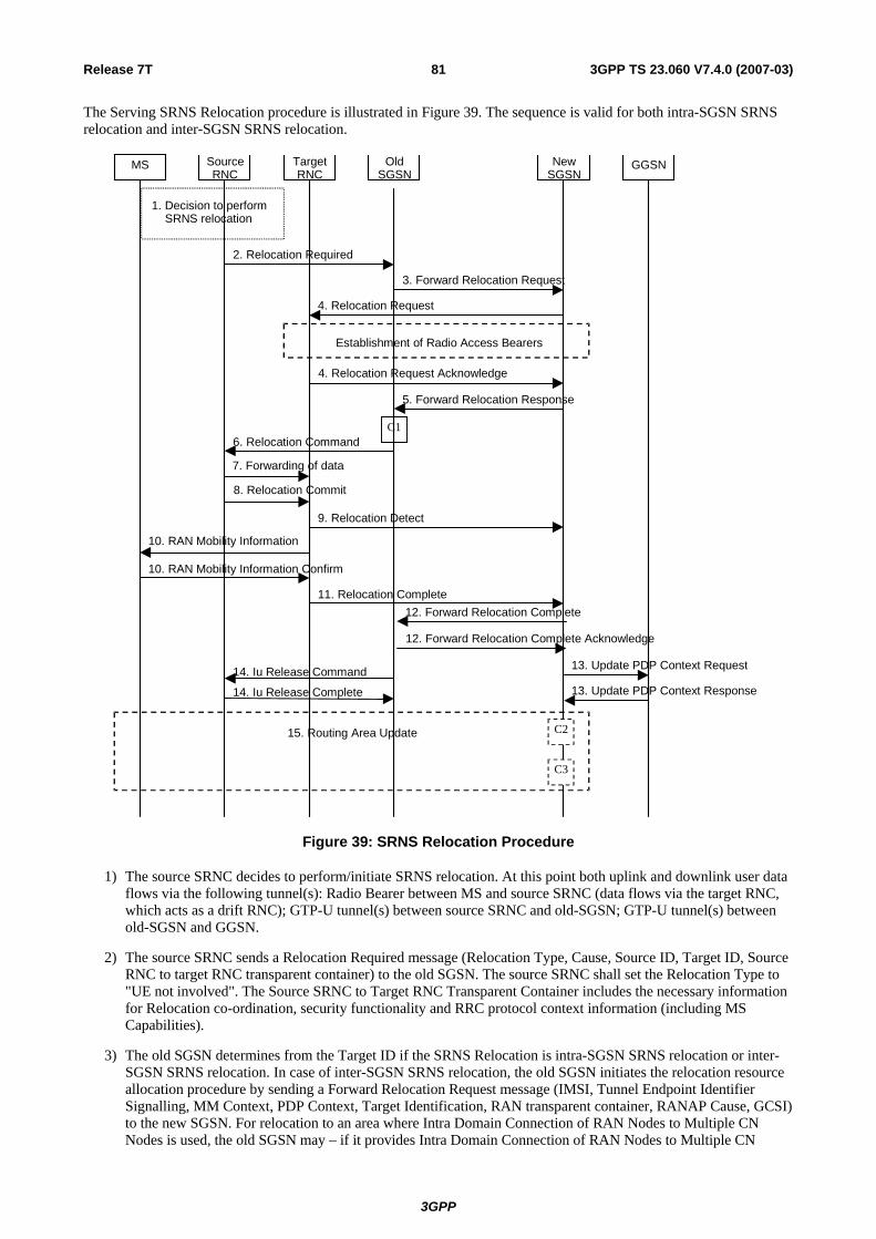
Release 7T 81 3GPP TS 23.060 V7.4.0 (2007-03)
The Serving SRNS Relocation procedure is illustrated in Figure 39. The sequence is valid for both intra-SGSN SRNS relocation and inter-SGSN SRNS relocation.
MS Target RNC
Source RNC
OldSGSN
NewSGSN
GGSN
3. Forward Relocation Request
4. Relocation Request
2. Relocation Required
6. Relocation Command
5. Forward Relocation Response
4. Relocation Request Acknowledge
9. Relocation Detect
10. RAN Mobility Information 10. RAN Mobility Information Confirm
Establishment of Radio Access Bearers
C1
1. Decision to perform SRNS relocation
8. Relocation Commit 7. Forwarding of data
11. Relocation Complete12. Forward Relocation Complete
15. Routing Area Update
13. Update PDP Context Request14. Iu Release Command
14. Iu Release Complete
C2
13. Update PDP Context Response
12. Forward Relocation Complete Acknowledge
C3
Figure 39: SRNS Relocation Procedure
1) The source SRNC decides to perform/initiate SRNS relocation. At this point both uplink and downlink user data flows via the following tunnel(s): Radio Bearer between MS and source SRNC (data flows via the target RNC, which acts as a drift RNC); GTP-U tunnel(s) between source SRNC and old-SGSN; GTP-U tunnel(s) between old-SGSN and GGSN.
2) The source SRNC sends a Relocation Required message (Relocation Type, Cause, Source ID, Target ID, Source RNC to target RNC transparent container) to the old SGSN. The source SRNC shall set the Relocation Type to "UE not involved". The Source SRNC to Target RNC Transparent Container includes the necessary information for Relocation co-ordination, security functionality and RRC protocol context information (including MS Capabilities).
3) The old SGSN determines from the Target ID if the SRNS Relocation is intra-SGSN SRNS relocation or inter-SGSN SRNS relocation. In case of inter-SGSN SRNS relocation, the old SGSN initiates the relocation resource allocation procedure by sending a Forward Relocation Request message (IMSI, Tunnel Endpoint Identifier Signalling, MM Context, PDP Context, Target Identification, RAN transparent container, RANAP Cause, GCSI) to the new SGSN. For relocation to an area where Intra Domain Connection of RAN Nodes to Multiple CN Nodes is used, the old SGSN may – if it provides Intra Domain Connection of RAN Nodes to Multiple CN
3GPP

Release 7T 82 3GPP TS 23.060 V7.4.0 (2007-03)
Nodes -have multiple target SGSNs for each relocation target in a pool area, in which case the old SGSN will select one of them to become the new SGSN, as specified in TS 23.236 [73]. The PDP context contains GGSN Address for User Plane and Uplink TEID for Data (to this GGSN Address and Uplink TEID for Data the old SGSN and the new SGSN send uplink packets). At the same time a timer is started on the MM and PDP contexts in the old SGSN (see the Routeing Area Update procedure in subclause "Location Management Procedures (Iu mode)"). The Forward Relocation Request message is applicable only in the case of inter-SGSN SRNS relocation. The old SGSN 'sets' the GCSI flag if the MM context contains GPRS CAMEL Subscription Information.
4) The new SGSN sends a Relocation Request message (Permanent NAS UE Identity, Cause, CN Domain Indicator, Source-RNC to target RNC transparent container, RABs to be setup) to the target RNC. Only the Iu Bearers of the RABs are setup between the target RNC and the new-SGSN as the existing Radio Bearers will be reallocated between the MS and the target RNC when the target RNC takes the role of the serving RNC. For each requested RAB, the RABs to be setup information elements shall contain information such as RAB ID, RAB parameters, Transport Layer Address, and Iu Transport Association. SGSN shall not establish RABs for PDP contexts with maximum bitrate for uplink and downlink of 0 kbit/s. . The list of RABs requested by the new SGSN may differ from list of RABs established in the Source RNC contained in the Source-RNC to target RNC transparent container. The target RNC shall not establish the RABs (as identified from the Source-RNC to target RNC transparent container) that did not exist in the source RNC prior to the relocation. The RAB ID information element contains the NSAPI value, and the RAB parameters information element gives the QoS profile. The Transport Layer Address is the SGSN Address for user data, and the Iu Transport Association corresponds to the uplink Tunnel Endpoint Identifier Data. The new SGSN may decide to establish Direct Tunnel unless it has received a 'set' GCSI flag from the old SGSN. If the new SGSN decides to establish Direct Tunnel, it provides to the target RNC the GGSN's Address for User Plane and TEID for Uplink data.
After all necessary resources for accepted RABs including the Iu user plane are successfully allocated; the target RNC shall send the Relocation Request Acknowledge message (RABs setup, RABs failed to setup) to the new SGSN. Each RAB to be setup is defined by a Transport Layer Address, which is the target RNC Address for user data, and an Iu Transport Association, which corresponds to the downlink Tunnel Endpoint Identifier for user data. For each RAB to be set up, the target RNC may receive simultaneously downlink user packets both from the source SRNC and from the new SGSN.
5) When resources for the transmission of user data between the target RNC and the new SGSN have been allocated and the new SGSN is ready for relocation of SRNS, the Forward Relocation Response message (Cause, RANAP Cause, and RAB Setup Information) is sent from the new SGSN to old SGSN. This message indicates that the target RNC is ready to receive from source SRNC the forwarded downlink PDUs, i.e. the relocation resource allocation procedure is terminated successfully. RANAP Cause is information from the target RNC to be forwarded to the source SRNC. The RAB Setup Information, one information element for each RAB, contains the RNC Tunnel Endpoint Identifier and the RNC IP address for data forwarding from the source SRNC to the target RNC. If the target RNC or the new SGSN failed to allocate resources, the RAB Setup Information element contains only NSAPI indicating that the source SRNC shall release the resources associated with the NSAPI. The Forward Relocation Response message is applicable only in case of inter-SGSN SRNS relocation.
6) The old SGSN continues the relocation of SRNS by sending a Relocation Command message (RABs to be released, and RABs subject to data forwarding) to the source SRNC. The old SGSN decides the RABs to be subject for data forwarding based on QoS, and those RABs shall be contained in RABs subject to data forwarding. For each RAB subject to data forwarding, the information element shall contain RAB ID, Transport Layer Address, and Iu Transport Association. These are the same Transport Layer Address and Iu Transport Association that the target RNC had sent to new SGSN in Relocation Request Acknowledge message, and these are used for forwarding of downlink N-PDU from source SRNC to target RNC. The source SRNC is now ready to forward downlink user data directly to the target RNC over the Iu interface. This forwarding is performed for downlink user data only.
7) The source SRNC may, according to the QoS profile, begin the forwarding of data for the RABs to be subject for data forwarding. The data forwarding at SRNS relocation shall be carried out through the Iu interface, meaning that the data exchanged between the source SRNC and the target RNC are duplicated in the source SRNC and routed at IP layer towards the target RNC. For each radio bearer which uses lossless PDCP the GTP-PDUs related to transmitted but not yet acknowledged PDCP-PDUs are duplicated and routed at IP layer towards the target RNC together with their related downlink PDCP sequence numbers. The source RNC continues transmitting duplicates of downlink data and receiving uplink data. Before the serving RNC role is not yet taken over by target RNC and when downlink user plane data starts to arrive to target RNC, the target RNC may buffer or discard arriving downlink GTP-PDUs according to the related QoS profile.
3GPP

Release 7T 83 3GPP TS 23.060 V7.4.0 (2007-03)
NOTE: The order of steps, starting from step 7 onwards, does not necessarily reflect the order of events. For instance, source RNC may start data forwarding (step 7) and send Relocation Commit message (step 8) almost simultaneously except in the delivery order required case where step 7 triggers step 8. Target RNC may send Relocation Detect message (step 9) and RAN Mobility Information message (step 10) at the same time. Hence, target RNC may receive RAN Mobility Information Confirm message (step 10) while data forwarding (step 7) is still underway, and before the new SGSN receives Update PDP Context Response message (step 11).
8) Before sending the Relocation Commit the uplink and downlink data transfer in the source, SRNC shall be suspended for RABs, which require delivery order. The source RNC shall start the data-forwarding timer. When the source SRNC is ready, the source SRNC shall trigger the execution of relocation of SRNS by sending a Relocation Commit message (SRNS Contexts) to the target RNC over the Iur interface. The purpose of this procedure is to transfer SRNS contexts from the source RNC to the target RNC, and to move the SRNS role from the source RNC to the target RNC. SRNS contexts are sent for each concerned RAB and contain the sequence numbers of the GTP-PDUs next to be transmitted in the uplink and downlink directions and the next PDCP sequence numbers that would have been used to send and receive data from the MS. For PDP context(s) using delivery order not required (QoS profile), the sequence numbers of the GTP-PDUs next to be transmitted are not used by the target RNC. PDCP sequence numbers are only sent by the source RNC for radio bearers, which used lossless PDCP [57]. The use of lossless PDCP is selected by the RNC when the radio bearer is set up or reconfigured.
If delivery order is required (QoS profile), consecutive GTP-PDU sequence numbering shall be maintained throughout the lifetime of the PDP context(s). Therefore, during the entire SRNS relocation procedure for the PDP context(s) using delivery order required (QoS profile), the responsible GTP-U entities (RNCs and GGSN) shall assign consecutive GTP-PDU sequence numbers to user packets belonging to the same PDP context for uplink and downlink, respectively.
9) The target RNC shall send a Relocation Detect message to the new SGSN when the relocation execution trigger is received. For SRNS relocation type "UE not involved", the relocation execution trigger is the reception of the Relocation Commit message from the Iur interface. When the Relocation Detect message is sent, the target RNC shall start SRNC operation.
10) The target SRNC sends a RAN Mobility Information message. This message contains UE information elements and CN information elements. The UE information elements include among others new SRNC identity and S-RNTI. The CN information elements contain among others Location Area Identification and Routeing Area Identification. The procedure shall be co-ordinated in all Iu signalling connections existing for the MS.
The target SRNC establishes and/or restarts the RLC, and exchanges the PDCP sequence numbers (PDCP-SNU, PDCP-SND) between the target SRNC and the MS. PDCP-SND is the PDCP sequence number for the next expected in-sequence downlink packet to be received in the MS per radio bearer, which used lossless PDCP in the source RNC. PDCP-SND confirms all mobile-terminated packets successfully transferred before the SRNC relocation. If PDCP-SND confirms reception of packets that were forwarded from the source SRNC, the target SRNC shall discard these packets. PDCP-SNU is the PDCP sequence number for the next expected in-sequence uplink packet to be received in the RNC per radio bearer, which used lossless PDCP in the source RNC. PDCP-SNU confirms all mobile originated packets successfully transferred before the SRNC relocation. If PDCP-SNU confirms reception of packets that were received in the source SRNC, the MS shall discard these packets.
Upon reception of the RAN Mobility Information message the MS may start sending uplink user data to the target SRNC. When the MS has reconfigured itself, it sends the RAN Mobility Information Confirm message to the target SRNC. This indicates that the MS is also ready to receive downlink data from the target SRNC.
If new the SGSN has already received the Update PDP Context Response message from the GGSN, it shall forward the uplink user data to GGSN over this new GTP-U tunnel. Otherwise, the new SGSN shall forward the uplink user data to that GGSN IP address and TEID(s), which the new SGSN had received earlier by the Forward Relocation Request message.
For all RABs, the target RNC should:
- start uplink reception of data and start transmission of uplink GTP-PDUs towards the new SGSN;
- start processing the already buffered and the arriving downlink GTP-PDUs and start downlink transmission towards the MS.
3GPP

Release 7T 84 3GPP TS 23.060 V7.4.0 (2007-03)
11) When the target SRNC receives the RAN Mobility Information Confirm message, i.e. the new SRNC—ID + S-RNTI are successfully exchanged with the MS by the radio protocols, the target SRNC shall initiate the Relocation Complete procedure by sending the Relocation Complete message to the new SGSN. The purpose of the Relocation Complete procedure is to indicate by the target SRNC the completion of the relocation of the SRNS to the CN.
12) Upon receipt of Relocation Complete message, if the SRNS Relocation is an inter SGSN SRNS relocation, the new SGSN signals to the old SGSN the completion of the SRNS relocation procedure by sending a Forward Relocation Complete message.
13) Upon receipt of the Relocation Complete message, the CN shall switch the user plane from the source RNC to the target SRNC. If the SRNS Relocation is an inter-SGSN SRNS relocation or if Direct Tunnel was established in intra-SGSN SRNS relocation, the new SGSN sends Update PDP Context Request messages (new SGSN Address, SGSN Tunnel Endpoint Identifier, QoS Negotiated, serving network identity, CGI/SAI, RAT type, CGI/SAI/RAI change support indication, NRSN, DTI) to the GGSNs concerned. The SGSN shall send the serving network identity to the GGSN. If Direct Tunnel is established the SGSN provides to GGSN the RNC's Address for User Plane and TEID for Downlink data and shall include the DTI to instruct the GGSN to apply Direct Tunnel specific error handling procedure as described in subclause 13.8. NRSN indicates SGSN support of the network requested bearer control. The GGSNs update their PDP context fields and return an Update PDP Context Response (GGSN Tunnel Endpoint Identifier, Prohibit Payload Compression, APN Restriction, CGI/SAI/RAI change report required, BCM) message. The Prohibit Payload Compression indicates that the SGSN should negotiate no data compression for this PDP context.
14) Upon receiving the Relocation Complete message or if it is an inter-SGSN SRNS relocation; the Forward Relocation Complete message, the old SGSN sends an Iu Release Command message to the source RNC. When the RNC data-forwarding timer has expired the source RNC responds with an Iu Release Complete.
15) After the MS has finished the RNTI reallocation procedure and if the new Routeing Area Identification is different from the old one, the MS initiates the Routeing Area Update procedure. See subclause "Location Management Procedures (Iu mode)". Note that it is only a subset of the RA update procedure that is performed, since the MS is in PMM-CONNECTED mode.
The new SGSN shall determine the Maximum APN restriction based on the received APN Restriction of each PDP context from the GGSN and then store the new Maximum APN restriction value.
If the SRNS Relocation is inter-SGSN, then the following CAMEL procedure calls shall be performed (see referenced procedures in TS 23.078 [8b]):
C1) CAMEL_GPRS_PDP_Context_Disconnection, CAMEL_GPRS_Detach and CAMEL_PS_Notification.
They are called in the following order:
- The CAMEL_GPRS_PDP_Context_Disconnection procedure is called several times: once per PDP context. The procedure returns as result "Continue".
- Then the CAMEL_GPRS_Detach procedure is called once. The procedure returns as result "Continue".
- Then the CAMEL_PS_Notification procedure is called once. The procedure returns as result "Continue".
If the SRNS Relocation is intra-SGSN, then the above mentioned CAMEL procedures calls shall not be performed.
If Routeing Area Update occurs, the SGSN shall determine whether Direct Tunnel can be used based on the received GPRS CAMEL Subscription Information. If Direct Tunnel can not be maintained the SGSN shall re-establish RABs and initiate the Update PDP Context procedure to update the IP Address and TEID for Uplink and Downlink data.
If Routeing Area Update occurs, then the following CAMEL procedure calls shall be performed (see referenced procedures in TS 23.078 [8b]):
C2) CAMEL_GPRS_Routeing_Area_Update_Session and CAMEL_PS_Notification.
They are called in the following order:
- The CAMEL_GPRS_Routeing_Area_Update_Session procedure is called. The procedure returns as result "Continue".
- Then, the CAMEL_PS_Notification procedure is called. The procedure returns as result "Continue".
3GPP

Release 7T 85 3GPP TS 23.060 V7.4.0 (2007-03)
C3) CAMEL_GPRS_Routeing_Area_Update_Context.
This procedure is called several times: once per PDP context. It returns as result ""Continue"".
For C2 and C3: refer to Routing Area Update procedure description for detailed message flow.
6.9.2.2.2 Combined Hard Handover and SRNS Relocation Procedure
This procedure is only performed for an MS in PMM-CONNECTED state in case the Iur interface is not available. In the context of this specification, the terms RNS or RNC refer also to a GERAN BSS or BSC (respectively) when serving a mobile in Iu mode.
The Combined Hard Handover and SRNS Relocation procedure is used to move the RAN to CN connection point at the RAN side from the source SRNC to the target RNC, while performing a hard handover decided by the RAN. In the procedure, the Iu links are relocated. If the target RNC is connected to the same SGSN as the source SRNC, an Intra-SGSN SRNS Relocation procedure is performed. If the routeing area is changed, this procedure is followed by an Intra-SGSN Routeing Area Update procedure. The SGSN detects that it is an intra-SGSN routeing area update by noticing that it also handles the old RA. In this case, the SGSN has the necessary information about the MS and there is no need to inform the HLR about the new MS location.
If the target RNC is connected to a different SGSN than the source SRNC, an Inter-SGSN SRNS Relocation procedure is performed. This procedure is followed by an Inter-SGSN Routeing Area Update procedure.
Figure 40 shows the situation before a Combined Hard Handover and SRNS Relocation procedure when source and target RNC are connected to different SGSNs. Figure 41 shows the situation after the Combined Hard Handover and SRNS Relocation procedure and RA update procedure have been completed. In the case described in Figure 40 and Figure 41 the MS is in PMM-CONNECTED state. Both figures are also applicable to BSS to RNS relocation and vice-versa, as well as for BSS to BSS relocation.
LA1, RA1
MS
HLR/AuC
old SGSN
GGSN
LA2, RA2
new SGSN
target RNCsource SRNC
new MSC/VLRold MSC/VLR
Figure 40: Before Combined Hard Handover and SRNS Relocation and Routeing Area Update
Before the SRNS Relocation and Routeing Area Update the MS is registered in the old SGSN and in the old MSC/VLR. The source RNC is acting as serving RNC.
3GPP

Release 7T 86 3GPP TS 23.060 V7.4.0 (2007-03)
LA1, RA1
MS
HLR/AuC
old SGSN
source RNC
GGSN
LA2, RA2
new SGSN
target SRNC
old MSC/VLR new MSC/VLR
Figure 41: After Combined Hard Handover and SRNS Relocation and Routeing Area Update
After the SRNS relocation and RA update, the MS is registered in the new SGSN and in the new MSC/VLR. The MS is in state PMM-CONNECTED towards the new SGSN and in MM IDLE state towards the new MSC/VLR. The target RNC is acting as serving RNC.
3GPP

Release 7T 87 3GPP TS 23.060 V7.4.0 (2007-03)
The Combined Hard Handover and SRNS Relocation procedure for the PS domain is illustrated in Figure 42. The sequence is valid for both intra-SGSN SRNS relocation and inter-SGSN SRNS relocation. Furthermore, this signalling flow is also applicable for BSS to RNS relocation and vice-versa, as well as BSS to BSS relocation.
MS Target RNC
Source RNC
OldSGSN
NewSGSN
GGSN
3. Forward Relocation Request
4. Relocation Request
2. Relocation Required
6. Relocation Command
5. Forward Relocation Response
4. Relocation Request Acknowledge
10. Relocation Detect
9. Forward SRNS Context9. Forward SRNS Context
9. Forward SRNS Context
8. RRC message
8. RRC message
1. Decision to perform SRNS Relocation MS Involved
MS detected by target RNC
Establishment of Radio Access Bearers
C1
7. Forwarding of data
9. Forward SRNS Context Acknowledge
11. Relocation Complete
12. Forward Relocation Complete
15. Routing Area Update
13. Update PDP Context Request14. Iu Release Command
14. Iu Release Complete 13. Update PDP Context Response
12. Forward Relocation Complete Acknowledge
C3
C2
Figure 42: Combined Hard Handover and SRNS Relocation Procedure
1) Based on measurement results and knowledge of the RAN topology, the source SRNC decides to initiate a combined hard handover and SRNS relocation. At this point both uplink and downlink user data flows via the following tunnel(s): Radio Bearer between the MS and the source SRNC (no drift RNC available); GTP-U tunnel(s) between the source SRNC and the old SGSN; GTP-U tunnel(s) between the old SGSN and the GGSN.
2) The source SRNC sends a Relocation Required message (Relocation Type, Cause, Source ID, Target ID, Source RNC To Target RNC Transparent Container) to the old SGSN. The source SRNC shall set Relocation Type to "UE Involved". Source RNC To Target RNC Transparent Container includes the necessary information for
3GPP

Release 7T 88 3GPP TS 23.060 V7.4.0 (2007-03)
relocation co-ordination, security functionality and RRC protocol context information (including MS Capabilities).
3) The old SGSN determines from the Target ID if the SRNS relocation is intra-SGSN SRNS relocation or inter-SGSN SRNS relocation. In case of inter-SGSN SRNS relocation the old SGSN initiates the relocation resource allocation procedure by sending a Forward Relocation Request message (IMSI, Tunnel Endpoint Identifier Signalling, MM Context, PDP Context, Target Identification, RAN Transparent Container, RANAP Cause, GCSI) to the new SGSN. For relocation to an area where Intra Domain Connection of RAN Nodes to Multiple CN Nodes is used, the old SGSN may – if it provides Intra Domain Connection of RAN Nodes to Multiple CN Nodes -have multiple target SGSNs for each relocation target in a pool area, in which case the old SGSN will select one of them to become the new SGSN, as specified in TS 23.236 [73]. PDP context contains GGSN Address for User Plane and Uplink TEID for Data (to this GGSN Address and Uplink TEID for Data, the old SGSN and the new SGSN send uplink packets). At the same time a timer is started on the MM and PDP contexts in the old SGSN (see Routeing Area Update procedure in subclause "Location Management Procedures (Iu mode)"). The Forward Relocation Request message is applicable only in case of inter-SGSN SRNS relocation. The old SGSN 'sets' the GCSI flag if the MM context contains GPRS CAMEL Subscription Information.
4) The new SGSN sends a Relocation Request message (Permanent NAS UE Identity, Cause, CN Domain Indicator, Source RNC To Target RNC Transparent Container, RAB To Be Setup) to the target RNC. For each RAB requested to be established, RABs To Be Setup shall contain information such as RAB ID, RAB parameters, Transport Layer Address, and Iu Transport Association. SGSN shall not establish RABs for PDP contexts with maximum bitrate for uplink and downlink of 0 kbit/s. The list of RABs requested by the new SGSN may differ from list of RABs established in the Source RNC contained in the Source-RNC to target RNC transparent container. The target RNC should not establish the RABs (as identified from the Source-RNC to target RNC transparent container) that did not exist in the source RNC prior to the relocation. The RAB ID information element contains the NSAPI value, and the RAB parameters information element gives the QoS profile. The Transport Layer Address is the SGSN Address for user data, and the Iu Transport Association corresponds to the uplink Tunnel Endpoint Identifier Data. The new SGSN may decide to establish Direct Tunnel unless it has received a 'set' GCSI flag from the old SGSN. If the new SGSN decides to establish Direct Tunnel, it provides to the target RNC the GGSN's Address for User Plane and TEID for Uplink data.
After all the necessary resources for accepted RABs including the Iu user plane are successfully allocated, the target RNC shall send the Relocation Request Acknowledge message (Target RNC To Source RNC Transparent Container, RABs Setup, RABs Failed To Setup) to the new SGSN. Each RAB to be setup is defined by a Transport Layer Address, which is the target RNC Address for user data, and the Iu Transport Association, which corresponds to the downlink Tunnel Endpoint Identifier for user data. The transparent container contains all radio-related information that the MS needs for the handover, i.e., a complete RRC message (e.g., Physical Channel Reconfiguration in UTRAN case, or Handover From UTRAN, or Handover Command in GERAN Iu mode case) to be sent transparently via CN and source SRNC to the MS. For each RAB to be set up, the target RNC may receive simultaneously downlink user packets both from the source SRNC and from the new SGSN.
5) When resources for the transmission of user data between target RNC and new SGSN have been allocated and the new SGSN is ready for relocation of SRNS, the Forward Relocation Response (Cause, RAN Transparent Container, RANAP Cause, Target-RNC Information) message is sent from the new SGSN to the old SGSN. This message indicates that the target RNC is ready to receive from source SRNC the forwarded downlink PDUs, i.e., the relocation resource allocation procedure is terminated successfully. RAN transparent container and RANAP Cause are information from the target RNC to be forwarded to the source SRNC. The Target RNC Information, one information element for each RAB to be set up, contains the RNC Tunnel Endpoint Identifier and RNC IP address for data forwarding from the source SRNC to the target RNC. The Forward Relocation Response message is applicable only in case of inter-SGSN SRNS relocation.
6) The old SGSN continues the relocation of SRNS by sending a Relocation Command message (Target RNC To Source RNC Transparent Container, RABs To Be Released, RABs Subject To Data Forwarding) to the source SRNC. The old SGSN decides the RABs to be subject for data forwarding based on QoS, and those RABs shall be contained in RABs subject to data forwarding. For each RAB subject to data forwarding, the information element shall contain RAB ID, Transport Layer Address, and Iu Transport Association. These are the same Transport Layer Address and Iu Transport Association that the target RNC had sent to new SGSN in Relocation Request Acknowledge message, and these are used for forwarding of downlink N-PDU from the source SRNC to the target RNC. The source SRNC is now ready to forward downlink user data directly to the target RNC over the Iu interface. This forwarding is performed for downlink user data only.
7) The source SRNC may, according to the QoS profile, begins the forwarding of data for the RABs to be subject for data forwarding.
3GPP

Release 7T 89 3GPP TS 23.060 V7.4.0 (2007-03)
NOTE: The order of steps, starting from step 7 onwards, does not necessarily reflect the order of events. For instance, source RNC may start data forwarding (step 7), send the RRC message to MS (step 8) and forward SRNS Context message to the old SGSN (step 9) almost simultaneously.
The data forwarding at SRNS relocation shall be carried out through the Iu interface, meaning that the GTP-PDUs exchanged between the source SRNC and the target RNC are duplicated in the source SRNC and routed at the IP layer towards the target RNC. For each radio bearer which uses lossless PDCP the GTP-PDUs related to transmitted but not yet acknowledged PDCP-PDUs are duplicated and routed at IP layer towards the target RNC together with their related downlink PDCP sequence numbers. The source RNC continues transmitting duplicates of downlink data and receiving uplink data.
Before the serving RNC role is not yet taken over by target RNC and when downlink user plane data starts to arrive to target RNC, the target RNC may buffer or discard arriving downlink GTP-PDUs according to the related QoS profile.
8) Before sending the RRC message the uplink and downlink data transfer shall be suspended in the source SRNC for RABs, which require delivery order. The RRC message is for example Physical Channel Reconfiguration for RNS to RNS relocation, or Intersystem to UTRAN Handover for BSS to RNS relocation, or Handover from UTRAN Command for BSS relocation, or Handover Command for BSS to BSS relocation. When the source SRNC is ready, the source RNC shall trigger the execution of relocation of SRNS by sending to the MS the RRC message provided in the Target RNC to source RNC transparent container, e.g., a Physical Channel Reconfiguration (UE Information Elements, CN Information Elements) message. UE Information Elements include among others new SRNC identity and S-RNTI. CN Information Elements contain among others Location Area Identification and Routeing Area Identification.
When the MS has reconfigured itself, it sends an RRC message e.g., a Physical Channel Reconfiguration Complete message to the target SRNC. If the Forward SRNS Context message with the sequence numbers is received, the exchange of packets with the MS may start. If this message is not yet received, the target RNC may start the packet transfer for all RABs, which do not require maintaining the delivery order.
9) The source SRNC continues the execution of relocation of SRNS by sending a Forward SRNS Context (RAB Contexts) message to the target RNC via the old and the new SGSN. The Forward SRNS Context message is acknowledged by a Forward SRNS Context Acknowledge message, from new to old SGSN. The purpose of this procedure is to transfer SRNS contexts from the source RNC to the target RNC, and to move the SRNS role from the source RNC to the target RNC. SRNS contexts are sent for each concerned RAB and contain the sequence numbers of the GTP PDUs next to be transmitted in the uplink and downlink directions and the next PDCP sequence numbers that would have been used to send and receive data from the MS. PDCP sequence numbers are only sent by the source RNC for the radio bearers which used lossless PDCP [57]. The use of lossless PDCP is selected by the RNC when the radio bearer is set up or reconfigured. For PDP context(s) using delivery order not required (QoS profile), the sequence numbers of the GTP-PDUs next to be transmitted are not used by the target RNC.
If delivery order is required (QoS profile), consecutive GTP-PDU sequence numbering shall be maintained throughout the lifetime of the PDP context(s). Therefore, during the entire SRNS relocation procedure for the PDP context(s) using delivery order required (QoS profile), the responsible GTP-U entities (RNCs and GGSN) shall assign consecutive GTP-PDU sequence numbers to user packets belonging to the same PDP context uplink and downlink, respectively.
The target RNC establishes and/or restarts the RLC and exchanges the PDCP sequence numbers (PDCP-SNU, PDCP-SND) between the target RNC and the MS. PDCP-SND is the PDCP sequence number for the next expected in-sequence downlink packet to be received by the MS per radio bearer, which used lossless PDCP in the source RNC. PDCP-SND confirms all mobile terminated packets successfully transferred before the SRNC relocation. If PDCP-SND confirms reception of packets that were forwarded from the source SRNC, then the target SRNC shall discard these packets. PDCP-SNU is the PDCP sequence number for the next expected in-sequence uplink packet to be received in the RNC per radio bearer, which used lossless PDCP in the source RNC. PDCP-SNU confirms all mobile originated packets successfully transferred before the SRNC relocation. If PDCP-SNU confirms reception of packets that were received in the source SRNC, the MS shall discard these packets.
10) The target RNC shall send a Relocation Detect message to the new SGSN when the relocation execution trigger is received. For SRNS relocation type "UE Involved", the relocation execution trigger may be received from the Uu interface; i.e., when target RNC detects the MS on the lower layers. When the Relocation Detect message is sent, the target RNC shall start SRNC operation.
3GPP

Release 7T 90 3GPP TS 23.060 V7.4.0 (2007-03)
11) When the target SRNC receives the appropriate RRC message, e.g. Physical Channel Reconfiguration Complete message or the Radio Bearer Release Complete message in UTRAN case, or the Handover To UTRAN Complete message or Handover Complete message in GERAN case, i.e. the new SRNC-ID + S-RNTI are successfully exchanged with the MS by the radio protocols, the target SRNC shall initiate a Relocation Complete procedure by sending the Relocation Complete message to the new SGSN. The purpose of the Relocation Complete procedure is to indicate by the target SRNC the completion of the relocation of the SRNS to the CN.
12) Upon receipt of Relocation Complete message, if the SRNS Relocation is an inter SGSN SRNS relocation, the new SGSN signals to the old SGSN the completion of the SRNS relocation procedure by sending a Forward Relocation Complete message.
13) Upon receipt of the Relocation Complete message, the CN shall switch the user plane from the source RNC to the target SRNC. If the SRNS Relocation is an inter-SGSN SRNS relocation or if Direct Tunnel was established in intra-SGSN SRNS relocation, the new SGSN sends Update PDP Context Request messages (new SGSN Address, SGSN Tunnel Endpoint Identifier, QoS Negotiated, serving network identity, CGI/SAI, RAT type, CGI/SAI/RAI change support indication, NRSN, DTI) to the GGSNs concerned. The SGSN shall send the serving network identity to the GGSN. If Direct Tunnel is established the SGSN provides to GGSN the RNC's Address for User Plane and TEID for Downlink data and shall include the DTI to instruct the GGSN to apply Direct Tunnel specific error handling procedure as described in clause 13.8. NRSN indicates SGSN support of the network requested bearer control. The GGSNs update their PDP context fields and return an Update PDP Context Response (GGSN Tunnel Endpoint Identifier, Prohibit Payload Compression, APN Restriction, CGI/SAI/RAI change report required, BCM) message. The Prohibit Payload Compression indicates that the SGSN should negotiate no data compression for this PDP context.
14) Upon receiving the Relocation Complete message or, if it is an inter-SGSN SRNS relocation, the Forward Relocation Complete message, the old SGSN sends an Iu Release Command message to the source RNC. When the RNC data-forwarding timer has expired, the source RNC responds with an Iu Release Complete message.
15) After the MS has finished the reconfiguration procedure and if the new Routeing Area Identification is different from the old one, the MS initiates the Routeing Area Update procedure. See subclause "Location Management Procedures (Iu mode)". Note that it is only a subset of the RA update procedure that is performed, since the MS is in PMM-CONNECTED state.
If the SRNS Relocation is inter-SGSN, then the following CAMEL procedure calls shall be performed (see referenced procedures in TS 23.078 [8b])
C1) CAMEL_GPRS_PDP_Context_Disconnection, CAMEL_GPRS_Detach and CAMEL_PS_Notification.
They are called in the following order:
- The CAMEL_GPRS_PDP_Context_Disconnection procedure is called several times: once per PDP context. The procedure returns as result "Continue".
- Then the CAMEL_GPRS_Detach procedure is called once. The procedure returns as result "Continue".
- Then the CAMEL_PS_Notification procedure is called once. The procedure returns as result "Continue".
The new SGSN shall determine the Maximum APN restriction based on the received APN Restriction of each PDP context from the GGSN and then store the new Maximum APN restriction value.
If the SRNS Relocation is intra-SGSN, then the above mentioned CAMEL procedures calls shall not be performed.
If Routeing Area Update occurs, the SGSN shall determine whether Direct Tunnel can be used based on the received GPRS CAMEL Subscription Information. If Direct Tunnel can not be maintained the SGSN shall re-establish RABs and initiate the Update PDP Context procedure to update the IP Address and TEID for Uplink and Downlink data.
If Routeing Area Update occurs, then the following CAMEL procedure calls shall be performed (see referenced procedures in TS 23.078 [8b]):
C2) CAMEL_GPRS_Routeing_Area_Update_Session and CAMEL_PS_Notification.
They are called in the following order:
- The CAMEL_GPRS_Routeing_Area_Update_Session procedure is called. In Figure 42, the procedure returns as result "Continue".
3GPP

Release 7T 91 3GPP TS 23.060 V7.4.0 (2007-03)
- Then the CAMEL_PS_Notification procedure is called. The procedure returns as result "Continue".
C3) CAMEL_GPRS_Routeing_Area_Update_Context.
This procedure is called several times: once per PDP context. It returns as result "Continue".
For C2 and C3: refer to Routing Area Update procedure description for detailed message flow.
6.9.2.2.3 Combined Cell / URA Update and SRNS Relocation Procedure
This procedure is only performed for an MS in PMM-CONNECTED state, where the Iur/Iur-g interface carries control signalling but no user data In the context of this specification, the terms RNS or RNC refer also to a GERAN BSS or BSC (respectively) when serving an MS in Iu mode.
The Combined Cell / URA Update and SRNS Relocation or Combined Cell/GRA Update and SBSS Relocation procedure is used to move the RAN to CN connection point at the RAN side from the source SRNC to the target RNC, while performing a cell re-selection in the RAN. In the procedure, the Iu links are relocated. If the target RNC is connected to the same SGSN as the source SRNC, an Intra-SGSN SRNS Relocation procedure is performed. If the routeing area is changed, this procedure is followed by an Intra-SGSN Routeing Area Update procedure. The SGSN detects that it is an intra-SGSN routeing area update by noticing that it also handles the old RA. In this case, the SGSN has the necessary information about the MS and there is no need to inform the HLR about the new MS location.
Before the Combined Cell / URA Update and SRNS Relocation or Combined Cell/GRA Update and SBSS Relocation and before the Routeing Area Update, the MS is registered in the old SGSN. The source RNC is acting as serving RNC or serving BSS.
After the Combined Cell / URA Update and SRNS Relocation or Combined Cell/GRA Update and SBSS Relocation and after the Routeing Area Update, the MS is registered in the new SGSN. The MS is in state PMM-CONNECTED towards the new SGSN, and the target RNC is acting as serving RNC.
3GPP

Release 7T 92 3GPP TS 23.060 V7.4.0 (2007-03)
The Combined Cell / URA Update and SRNS Relocation or Combined Cell/GRA Update and SBSS relocation procedure for the PS domain is illustrated in Figure 43. The sequence is valid for both intra-SGSN SRNS relocation and inter-SGSN SRNS relocation. This signalling flow is also applicable to BSS to RNS relocation and vice-versa, as well as for BSS to BSS relocation.
MS Target RNC
Source RNC
OldSGSN
NewSGSN
GGSN
3. Forward Relocation Request
4. Relocation Request
2. Relocation Required
6. Relocation Command
5. Forward Relocation Response
4. Relocation Request Acknowledge
9. Relocation Detect10. Cell Update Confirm/ URA Update Confirm orCell Update Confirm/GRA Update Confirm
10. UTRAN Mobility Information Confirm
Establishment of Radio Access Bearers
C1
1. Cell Update/ URA Update or Cell Update/GRA update
8. Relocation Commit 7. Forwarding of data
11. Relocation Complete
12. Forward Relocation Complete
15. Routing Area Update
13. Update PDP Context Request14. Iu Release Command
14. Iu Release Complete
C2
13. Update PDP Context Response
12. Forward Relocation Complete Acknowledge
C3
Figure 43: Combined Cell / URA Update and SRNS Relocation Procedure
1) The MS sends a Cell Update / URA Update or a Cell Update / GRA Update message to the source SRNC (if the cell is located under another RNC the message is routed via the DRNC to SRNC over the Iur). The source SRNC decides whether or not to perform a combined cell / URA update and SRNS relocation towards the target RNC. The rest of this subclause describes the case where a combined cell / URA update and SRNS relocation applies. In this case no radio bearer is established between the source SRNC and the UE. Nonetheless the following tunnel(s) are established: GTP-U tunnel(s) between source SRNC and old-SGSN; GTP-U tunnel(s) between old-SGSN and GGSN.
2) The source SRNC sends a Relocation Required message (Relocation Type, Cause, Source ID, Target ID, Source RNC to Target RNC Transparent Container) to the old SGSN. The source SRNC shall set Relocation Type to "UE not involved". Source RNC to Target RNC Transparent Container includes the necessary information for Relocation co-ordination, security functionality, and RRC protocol context information (including MS Capabilities).
3) The old SGSN determines from the Target ID if the SRNS Relocation is intra-SGSN SRNS relocation or inter-SGSN SRNS relocation. In the case of inter-SGSN SRNS relocation the old SGSN initiates the relocation resource allocation procedure by sending a Forward Relocation Request (IMSI, Tunnel Endpoint Identifier
3GPP

Release 7T 93 3GPP TS 23.060 V7.4.0 (2007-03)
Signalling, MM Context, PDP Context, Target Identification, RAN Transparent Container, RANAP Cause, GCSI) message to the new SGSN. For relocation to an area where Intra Domain Connection of RAN Nodes to Multiple CN Nodes is used, the old SGSN may – if it provides Intra Domain Connection of RAN Nodes to Multiple CN Nodes -have multiple target SGSNs for each relocation target in a pool area, in which case the old SGSN will select one of them to become the new SGSN, as specified in TS 23.236 [73]. PDP context contains GGSN Address for User Plane and Uplink TEID for Data (to this GGSN Address and Uplink TEID for Data, the old SGSN and the new SGSN send uplink packets). At the same time a timer is started on the MM and PDP contexts in the old SGSN, see Routeing Area Update procedure in subclause "Location Management Procedures (Iu mode)". The Forward Relocation Request message is applicable only in case of inter-SGSN SRNS relocation. The old SGSN 'sets' the GCSI flag if the MM context contains GPRS CAMEL subscription information.
4) The new SGSN sends a Relocation Request message (Permanent NAS UE Identity, Cause, CN Domain Indicator, Source RNC to Target RNC Transparent Container, RABs To Be Setup) to the target RNC. For each requested RAB, RABs To Be Setup shall contain information such as RAB ID, RAB parameters, Transport Layer Address, and Iu Transport Association. SGSN shall not establish RABs for PDP contexts with maximum bitrate for uplink and downlink of 0 kbit/s. The list of RABs requested by the SGSN may differ from list of RABs available in the Source RNC. The target RNC should not establish the RABs (as identified from the Source-RNC to target RNC transparent container) that did not exist in the source RNC prior to the relocation. The RAB ID information element contains the NSAPI value, and the RAB parameters information element gives the QoS profile. The Transport Layer Address is the SGSN Address for user data, and the Iu Transport Association corresponds to the uplink Tunnel Endpoint Identifier Data. The new SGSN may decide to establish Direct Tunnel unless it has received a 'set' GCSI flag from the old SGSN. If the new SGSN decides to establish Direct Tunnel, it provides to the target RNC the GGSN's Address for User Plane and TEID for Uplink data.
After all necessary resources for accepted RABs including the Iu user plane are successfully allocated, the target RNC shall send the Relocation Request Acknowledge message (RABs setup, RABs failed to setup) to the new SGSN. Each RAB to be setup is defined by a Transport Layer Address, which is the target RNC Address for user data, and a Iu Transport Association which corresponds to the downlink Tunnel Endpoint Identifier for user data.
After the new SGSN receives the Relocation Request Acknowledge message, the GTP-U tunnels are established between the target RNC and the new-SGSN.
The target-RNC may simultaneously receive for each RAB to be set up downlink user packets both from the source SRNC and from the new SGSN.
5) When resources for the transmission of user data between the target RNC and the new SGSN have been allocated and the new SGSN is ready for relocation of SRNS, the Forward Relocation Response message (Cause, RANAP Cause, and Target RNC Information) is sent from the new SGSN to the old SGSN. This message indicates that the target RNC is ready to receive from the source SRNC the forwarded downlink packets, i.e., the relocation resource allocation procedure is terminated successfully. RANAP Cause is information from the target RNC to be forwarded to the source SRNC. The RAB Setup Information, one information element for each RAB, contains the RNC Tunnel Endpoint Identifier and RNC IP address for data forwarding from the source SRNC to the target RNC. If the target RNC or the new SGSN failed to allocate resources, the RAB Setup Information element contains only NSAPI indicating that the source SRNC shall release the resources associated with the NSAPI. The Forward Relocation Response message is applicable only in case of inter-SGSN SRNS relocation.
6) The old SGSN continues the relocation of SRNS by sending a Relocation Command (RABs to be released, and RABs subject to data forwarding) message to the source SRNC. The old SGSN decides the RABs subject to data forwarding based on QoS, and those RABs shall be contained in RABs subject to data forwarding. For each RAB subject to data forwarding, the information element shall contain RAB ID, Transport Layer Address, and Iu Transport Association. These are the same Transport Layer Address and Iu Transport Association that the target RNC had sent to new SGSN in Relocation Request Acknowledge message, and these are used for forwarding of downlink N-PDU from the source SRNC to the target RNC. The source SRNC is now ready to forward downlink data directly to the target RNC over the Iu interface. This forwarding is performed for downlink user data only.
7) The source SRNC may, according to the QoS profile, begin the forwarding of data for the RABs subject to data forwarding and starts the data-forwarding timer. The data forwarding at SRNS relocation shall be carried out through the Iu interface, meaning that the data exchanged between the source SRNC and the target RNC are duplicated in the source SRNC and routed at the IP layer towards the target RNC. For each radio bearer which uses lossless PDCP the GTP-PDUs related to transmitted but not yet acknowledged PDCP-PDUs are duplicated
3GPP

Release 7T 94 3GPP TS 23.060 V7.4.0 (2007-03)
and routed at IP layer towards the target RNC together with their related downlink PDCP sequence numbers. The source RNC continues transmitting duplicates of downlink data and receiving uplink data.
NOTE: The order of steps, starting from step 7 onwards, does not necessarily reflect the order of events. For instance, source RNC may send data forwarding (step 7) and start Relocation Commit message (step 8) almost simultaneously. Target RNC may send Relocation Detect message (step 9) and Cell Update Confirm/URA Update Confirm (or Cell Update Confirm/GRA Update Confirm) message (step 10) at the same time. Hence, target RNC may receive the UTRAN or GERAN Mobility Information Confirm message from MS (step 10) while data forwarding (step 8) is still underway, and before the new SGSN receives Update PDP Context Response message (step 11).
Before the serving RNC role is not yet taken over by target RNC and when downlink user plane data starts to arrive to target RNC, the target RNC may buffer or discard arriving downlink GTP-PDUs according to the related QoS profile.
8) Before sending the Relocation Commit the uplink and downlink data transfer in the source, SRNC shall be suspended for RABs, which require delivery order.
When the source SRNC is ready, the source SRNC shall trigger the execution of relocation of SRNS by sending a Relocation Commit message (SRNS Contexts) to the target RNC over the UTRAN Iur interface or over the GERAN Iur-g interface, respectively. The purpose of this procedure is to transfer SRNS contexts from the source RNC to the target RNC, and to move the SRNS role from the source RNC to the target RNC. SRNS contexts are sent for each concerned RAB and contain the sequence numbers of the GTP-PDUs next to be transmitted in the uplink and downlink directions and the next PDCP sequence numbers that would have been used to send and receive data from the MS. . PDCP sequence numbers are only sent by the source RNC for radio bearers, which used lossless PDCP [57]. The use of lossless PDCP is selected by the RNC when the radio bearer is set up or reconfigured. For PDP context(s) using delivery order not required (QoS profile), the sequence numbers of the GTP-PDUs next to be transmitted are not used by the target RNC.
If delivery order is required (QoS profile), consecutive GTP-PDU sequence numbering shall be maintained throughout the lifetime of the PDP context(s). Therefore, during the entire SRNS relocation procedure for the PDP context(s) using delivery order required (QoS profile), the responsible GTP-U entities (RNCs and GGSN) shall assign consecutive GTP-PDU sequence numbers to user packets belonging to the same PDP context for uplink and downlink respectively.
9) The target RNC shall send a Relocation Detect message to the new SGSN when the relocation execution trigger is received. For SRNS relocation type "UE not involved", the relocation execution trigger is the reception of the Relocation Commit message from the Iur interface. When the Relocation Detect message is sent, the target RNC shall start SRNC operation.
10) The target SRNC sends a Cell Update Confirm / URA Update Confirm or Cell Update Confirm / GRA Update Confirm message. This message contains UE information elements and CN information elements. The UE information elements include among others new SRNC identity and S-RNTI. The CN information elements contain among others Location Area Identification and Routeing Area Identification. The procedure shall be co-ordinated in all Iu signalling connections existing for the MS.
Upon reception of the Cell Update Confirm / URA Update Confirm or Cell Update Confirm / GRA Update Confirm message the MS may start sending uplink user data to the target SRNC. When the MS has reconfigured itself, it sends the RAN Mobility Information Confirm message to the target SRNC. This indicates that the MS is also ready to receive downlink data from the target SRNC.
If the new SGSN has already received the Update PDP Context Response message from the GGSN, it shall forward the uplink user data to the GGSN over this new GTP-U tunnel. Otherwise, the new SGSN shall forward the uplink user data to that GGSN IP address and TEID(s), which the new SGSN had received earlier by the Forward Relocation Request message.
The target SRNC and the MS exchange the PDCP sequence numbers; PDCP-SNU and PDCP-SND. PDCP-SND is the PDCP sequence number for the next expected in-sequence downlink packet to be received in the MS per radio bearer, which used lossless PDCP in the source RNC. PDCP-SND confirms all mobile terminated packets successfully transferred before the SRNC relocation procedure. . If PDCP-SND confirms the reception of packets that were forwarded from the source SRNC, the target SRNC shall discard these packets. PDCP-SNU is the PDCP sequence number for the next expected in-sequence uplink packet to be received in the RNC per radio bearer, which used lossless PDCP in the source RNC. PDCP-SNU confirms all mobile originated packets
3GPP

Release 7T 95 3GPP TS 23.060 V7.4.0 (2007-03)
successfully transferred before the SRNC relocation. If PDCP-SNU confirms reception of packets that were received in the source SRNC, the target SRNC shall discard these packets.
11) When the target SRNC receives the RAN Mobility Information Confirm message, i.e. the new SRNC-ID + S-RNTI are successfully exchanged with the MS by the radio protocols, the target SRNC shall initiate the Relocation Complete procedure by sending the Relocation Complete message to the new SGSN. The purpose of the Relocation Complete procedure is to indicate by the target SRNC the completion of the relocation of the SRNS to the CN.
12) Upon receipt of Relocation Complete message, if the SRNS Relocation is an inter SGSN SRNS relocation, the new SGSN signals to the old SGSN the completion of the SRNS relocation procedure by sending a Forward Relocation Complete message.
13) Upon receipt of the Relocation Complete message, the CN shall switch the user plane from the source RNC to the target SRNC. If the SRNS Relocation is an inter-SGSN SRNS relocation or if Direct Tunnel was established in intra-SGSN SRNS relocation, the new SGSN sends Update PDP Context Request messages (new SGSN Address, SGSN Tunnel Endpoint Identifier, QoS Negotiated, serving network identity, CGI/SAI, RAT type, CGI/SAI/RAI change support indication, NRSN, DTI) to the GGSNs concerned. The SGSN shall send the serving network identity to the GGSN. If Direct Tunnel is established the SGSN provides to GGSN the RNC's Address for User Plane and TEID for Downlink data and shall include the DTI to instruct the GGSN to apply Direct Tunnel specific error handling procedure as described in clause 13.8. NRSN indicates SGSN support of the network requested bearer control. The GGSNs update their PDP context fields and return an Update PDP Context Response (GGSN Tunnel Endpoint Identifier, Prohibit Payload Compression, APN Restriction, CGI/SAI/RAI change report required, BCM) message. The Prohibit Payload Compression indicates that the SGSN should negotiate no data compression for this PDP context.
14) Upon receiving the Relocation Complete message or if it is an inter-SGSN SRNS relocation, the Forward Relocation Complete message, the old SGSN sends an Iu Release Command message to the source RNC. When the RNC data-forwarding timer has expired the source RNC responds with an Iu Release Complete.
15) After the MS has finished the Cell / URA update or the Cell / GRA update and RNTI reallocation procedure and if the new Routeing Area Identification is different from the old one, the MS initiates the Routeing Area Update procedure. See subclause "Location Management Procedures (Iu mode)". Note that it is only a subset of the RA update procedure that is performed, since the MS is in PMM-CONNECTED state.
If the SRNS Relocation is inter-SGSN, then the following CAMEL procedure calls shall be performed (see referenced procedures in TS 23.078 [8b])
C1) CAMEL_GPRS_PDP_Context_Disconnection, CAMEL_GPRS_Detach and CAMEL_PS_Notification.
They are called in the following order:
- The CAMEL_GPRS_PDP_Context_Disconnection procedure is called several times: once per PDP context. The procedure returns as result "Continue".
- Then the CAMEL_GPRS_Detach procedure is called once. The procedure returns as result "Continue".
- Then the CAMEL_PS_Notification procedure is called once. The procedure returns as result "Continue".
The new SGSN shall determine the Maximum APN restriction based on the received APN Restriction of each PDP context from the GGSN and then store the new Maximum APN restriction value.
If the SRNS Relocation is intra-SGSN, then the above mentioned CAMEL procedures calls shall not be performed.
If Routeing Area Update occurs, the SGSN shall determine whether Direct Tunnel can be used based on the received GPRS CAMEL Subscription Information. If Direct Tunnel, can not be maintained the SGSN shall re-establish RABs and initiate the Update PDP Context procedure to update the IP Address and TEID for Uplink and Downlink data.
If Routeing Area Update occurs, then the following CAMEL procedure calls shall be performed (see referenced procedures in TS 23.078 [8b]):
C2) CAMEL_GPRS_Routeing_Area_Update_Session and CAMEL_PS_Notification.
They are called in the following order:
3GPP

Release 7T 96 3GPP TS 23.060 V7.4.0 (2007-03)
- The CAMEL_GPRS_Routeing_Area_Update_Session procedure is called. The procedure returns as result "Continue".
- Then, the CAMEL_PS_Notification procedure is called. The procedure returns as result "Continue".
C3) CAMEL_GPRS_Routeing_Area_Update_Context.
This procedure is called several times: once per PDP context. It returns as result "Continue". For C2 and C3: refer to Routing Area Update procedure description for detailed message flow.
6.9.2.2.4 SRNS Relocation Cancel Procedure
The purpose of the SRNS Relocation Cancel procedure is to cancel an ongoing SRNS relocation. The SRNS Relocation Cancel procedure may be initiated during or after the Relocation Preparation procedure and may be initiated by the source RNC.
The SRNS Relocation Cancel procedure is illustrated in Figure 44. The sequence is valid for cancelling both an intra-SGSN SRNS relocation and an inter-SGSN SRNS relocation.
MS Target RNC
Source RNC
OldSGSN
NewSGSN
GGSN
5. Relocation Cancel Response
3. Relocation Cancel Request
1. Ongoing Relocation procedure
2b. Relocation Cancel
2a. Timer expiration or other error event
4. Iu Release Command
4. Iu Release Complete
6. Relocation Cancel Ack.
C2
C3
Figure 44: SRNS Cancel Relocation Procedure
1) An SRNS Relocation procedure has started, as specified in section 6.9.2.2.1.
2a) The SRNS Cancel Relocation may be initiated by a timer expiry or by an error event in the source RNC.
2b) When one of conditions in 2a is satisfied, the source RNC sends a Relocation Cancel (Cause) to the old SGSN. Cause indicates the reason for cancelling the ongoing SRNS relocation.
3) The old SGSN sends a Relocation Cancel Request (IMSI, RANAP Cause) to the new SGSN to indicate that the ongoing SRSN relocation should be cancelled. RANAP Cause contains the cause value received by the source RNC in the Relocation Cancel message.
4) The new SGSN sends an Iu Release Command (Cause) to request from the target RNC to release the Iu resources already allocated for the SRNS relocation, or to cancel the ongoing allocation of Iu resources for the SRNS relocation. Cause is set equal to RANAP Cause, i.e. to whatever cause value was included in the Relocation Cancel Request received from old SGSN. The target RNC releases the requested Iu resources and responds with an Iu Release Complete.
3GPP

Release 7T 97 3GPP TS 23.060 V7.4.0 (2007-03)
5) The new SGSN acknowledges the cancellation of the ongoing SRNS Relocation by sending a Relocation Cancel Response to the old SGSN.
6) The old SGSN responds to the source RNC with a Relocation Cancel Ack message.
If the SRNS Relocation is inter-SGSN, then the following CAMEL procedure calls shall be performed (see referenced procedures in TS 23.078 [8b]):
C2) CAMEL_GPRS_Routeing_Area_Update_Session and CAMEL_PS_Notification.
They are called in the following order:
- The procedure CAMEL_GPRS_Routeing_Area_Update_Session is called. The procedure returns as result "Continue".
- Then the procedure CAMEL_PS_Notification is called. The procedure returns as result "Continue".
C3) CAMEL_GPRS_Routeing_Area_Update_Context.
The procedure is called several times: once per PDP context. It returns as result "Continue".
For C2 and C3: refer to Routing Area Update procedure description for detailed message flow.
6.9.3 Periodic RA and LA Updates All GPRS-attached MSs, except A/Gb mode MSs in class-B mode of operation engaged in CS communication, shall perform periodic RA updates. MSs that are IMSI-attached and not GPRS-attached shall perform periodic LA updates. Periodic RA updates are equivalent to intra SGSN routeing area updates as described in clause "Intra SGSN Routeing Area Update", with Update Type indicating periodic RA update. For MSs that are both IMSI-attached and GPRS-attached, the periodic updates depend on the mode of operation of the network:
- If the network operates in mode I, periodic RA updates shall be performed, and periodic LA updates shall not be performed. In this case, the MSC/VLR shall disable implicit detach for GPRS-attached MSs and instead rely on the SGSN to receive periodic RA updates. If periodic RA updates are not received in the SGSN and the SGSN detaches the MS, the SGSN shall notify the MSC/VLR by sending an IMSI Detach Indication message.
- If the network operates in mode II or mode III, both periodic RA updates and periodic LA updates shall be performed independently. RA updates are performed towards the SGSN, and LA updates are performed towards the MSC/VLR.
In A/Gb mode, the periodic RA update timer in the MS is stopped when an LLC PDU is sent since all sent LLC PDUs set the MM context state to READY. The periodic RA update timer is reset and started when the state returns to STANDBY.
In Iu mode, the periodic RA update timer in the MS is stopped when the MM context enters the PMM-CONNECTED state. The periodic RA update timer is reset and started when the state returns to PMM-IDLE state.
If the MS could not successfully complete the periodic RA update procedure after a retry scheme while the MS was in PS coverage, the MS shall wait a back-off time equal to the periodic LA update timer broadcast by the network before restarting the periodic RA update procedure.
6.9.4 PS Handover Procedure The PS Handover procedure is used to handover an MS with one or more packet flows from a source cell to a target cell. The source and target cells can be located within either the same BSS (Intra BSS HO), different BSSs within the same SGSN (Intra SGSN HO) or belonging to different SGSNs (Inter SGSN HO), or systems with different radio access types (Inter RAT HO, Inter mode HO).
While the MS is still in the source cell:
- Radio resources in the target cell are allocated and signalled to the MS.
- System information of the target cell needed for access in the target cell is signalled to the MS.
The complete PS Handover procedures are defined in TS 43.129 [87].
3GPP

Release 7T 98 3GPP TS 23.060 V7.4.0 (2007-03)
6.10 Tunnelling of non-GSM Signalling Messages Function (A/Gb mode)
Tunnelling of Messages (TOM) is an optional protocol layer that uses the LLC unacknowledged mode procedures to tunnel messages between the MS and the SGSN (see TS 44.064 [15]). TOM uses two LLC SAPs for communication between the MS and the SGSN; one for high-priority messages and one for low-priority messages. A network that supports TIA/EIA-136 [49] shall support the TOM protocol and the Gs interface.
Upon receiving a non-GSM signalling message from an MS via the TOM protocol, the SGSN forwards the message to a non-GSM MSC/VLR using the BSSAP+ protocol (see GSM 09.18). The specific Gs interface used by the SGSN is determined by the:
- RAI associated with the current location of the MS when the SGSN does not provide functionality for the Intra Domain Connection of RAN Nodes to Multiple CN Nodes. When the SGSN provides functionality for Intra Domain Connection of RAN Nodes to Multiple CN Nodes, the SGSN uses the RAI and a hash value from the IMSI to determine the Gs interface; and
- information in the TOM protocol header.
Upon receiving a non-GSM signalling message from a non-GSM MSC/VLR via the BSSAP+ protocol, the SGSN forwards the message to a specific MS using the TOM protocol. The specific MS is determined by the SGSN based on the content of the BSSAP+ header.
The control plane between an MS and a non-GSM MSC/VLR that uses tunnelling procedures for non-GSM signalling is shown in Figure 45.
Non-GSM MSC/VLR
Relay
Network Service
BSSAP+
Non-GSM signalling
TOM
LLC
RLC
MAC
GSM RF
TOM
LLC
BSSGP
L1bis
RLC
MAC
GSM RF
BSSGP
L1bis
Relay
MTP2
L1
MTP3
MTP2
L1
MTP3
BSSAP+
Non-GSM signalling
Um Gb GsMS BSS SGSN
Network Service
SCCP
SCCP
Figure 45: Control Plane MS - Non-GSM MSC/VLR
6.10.1 Uplink Tunnelling of non-GSM Signalling Messages Procedure The Uplink Tunnelling of non-GSM Signalling Messages procedure is illustrated in Figure 46.
BSS SGSNNon-GSMMSC/VLR
2. Uplink Tunnel Request
MS
1. TOM Protocol Envelope
Figure 46: Uplink Tunnelling of non-GSM Signalling Messages Procedure
1) The MS sends a TOM Protocol Envelope (Non-GSM Signalling Message) to the SGSN either in ciphered or clear mode. The TOM protocol header contains information about the application using the TOM facility and any other TOM Protocol Discriminator-specific information. The TOM Protocol Envelope is received on one of the two LLC SAPs used for tunnelling of messages.
3GPP

Release 7T 99 3GPP TS 23.060 V7.4.0 (2007-03)
2) The SGSN identifies the non-GSM MSC/VLR to which to forward the non-GSM signalling message. It then sends a BSSAP+ Uplink Tunnel Request (IMSI, SGSN Address, TOM Priority, Cipher, Non-GSM Signalling Message) message to the identified non-GSM MSC/VLR. The Cipher parameter is set to cipher if the TOM Protocol Envelope was received in ciphered form by the LLC layer. Otherwise, it is set to not cipher. TOM Priority is set to high priority if the TOM Protocol Envelope was received on the high-priority LLC SAP, Otherwise, it is set to low priority.
6.10.2 Downlink Tunnelling of non-GSM Signalling Messages Procedure The Downlink Tunnelling of non-GSM Signalling Messages procedure is illustrated in Figure 47.
BSS SGSNNon-GSMMSC/VLR
1. Downlink Tunnel Request
MS
2. TOM Protocol Envelope
Figure 47: Downlink Tunnelling of non-GSM Signalling Messages Procedure
1) The non-GSM MSC/VLR sends a BSSAP+ Downlink Tunnel Request (IMSI, VLR Address, TOM Priority, Cipher, Non-GSM Signalling Message) message to the SGSN associated with the MS. TOM Priority indicates whether the SGSN shall select the high-priority or low-priority LLC SAP when forwarding the non-GSM signalling message to the MS. Cipher indicates whether or not the SGSN shall cipher the non-GSM signalling message before forwarding it to the MS.
2) The SGSN sends a TOM Protocol Envelope (Non-GSM Signalling Message) to the MS using the selected LLC SAP.
6.11 Subscriber Management Function The Subscriber Management function provides a mechanism to inform the nodes about changes of the GPRS subscription data for a specific GPRS subscriber.
6.11.1 Subscriber Management Procedures Whenever the GPRS subscription data is changed for a GPRS subscriber in the HLR, and the changes affect the GPRS subscription data stored in the SGSN, the SGSN node shall be informed about these changes by means of the following procedures:
- Insert Subscriber Data procedure, used to add or modify GPRS subscription data in the SGSN; or Delete Subscriber Data procedure, used to remove PS subscription data in the SGSN.
- Delete Subscriber Data procedure, used to remove GPRS subscription data from the SGSN.
6.11.1.1 Insert Subscriber Data Procedure
In addition to the insertion and modification of general GPRS subscription data for a GPRS subscriber, see TS 29.002 [23], the HLR may request the insertion or modification of one or several new or existing PDP contexts in the SGSN. It should be noted that the modification may trigger a PDP Context Modification procedure as described in clause "Modification Procedures". In particular, the following PDP context parameters may be modified by the HLR:
- QoS Profile Subscribed; and
- VPLMN Address Allowed.
3GPP

Release 7T 100 3GPP TS 23.060 V7.4.0 (2007-03)
The Insert Subscriber Data procedure is illustrated in Figure 48.
1. Insert Subscriber Data
2. Insert Subscriber Data Ack
SGSN HLR
Figure 48: Insert Subscriber Data Procedure
1) The HLR sends an Insert Subscriber Data (IMSI, GPRS Subscription Data) message to the SGSN.
2) The SGSN updates its GPRS subscription data and acknowledges the Insert Subscriber Data message by returning an Insert Subscriber Data Ack (IMSI) message. For each PDP context that is included in GPRS Subscription Data the SGSN shall check whether it is a new, an active, or an inactive PDP context:
- For a new or inactive PDP context, no further action is required except storage in the SGSN.
- For an active PDP context, the SGSN shall in addition compare the new QoS Subscribed with QoS Negotiated and shall, if necessary, initiate a PDP Context Modification procedure as described in subclause "Modification Procedures". Furthermore, if VPLMN Address Allowed is changed, the SGSN shall, if necessary (e.g., if the PDP context is currently routed via a GGSN in the VPLMN and VPLMN Address Allowed is changed to not allowed), initiate a PDP Context Deactivation procedure as explained in clause 9.2.4.
6.11.1.2 Delete Subscriber Data Procedure
In addition to the deletion of general GPRS subscription data for a subscriber, see TS 29.002 [23], the HLR may request the deletion of one or several PDP contexts from the SGSN.
The Delete Subscriber Data procedure is illustrated in Figure 49.
1. Delete Subscriber Data
2. Delete Subscriber Data Ack
SGSN HLR
Figure 49: Delete Subscriber Data Procedure
1) The HLR sends a Delete Subscriber Data (IMSI, PDP Context Identifiers List) message to the SGSN.
2) The SGSN acknowledges the Delete Subscriber Data message by returning a Delete Subscriber Data Ack (IMSI) message. For each PDP context identifier included in PDP Context Identifiers List, the SGSN shall check whether it belongs to an active or an inactive PDP context:
- For an inactive PDP context no further action is required except deletion of the PDP context.
- For an active PDP context, the SGSN shall initiate the PDP Context Deactivation Initiated by the SGSN procedure as explained in subclause "Deactivation Procedures" before the PDP context is deleted.
6.12 Service Request Procedure (Iu mode) The Service Request procedure is used by a 3G-MS in PMM-IDLE state to request the establishment of a secure connection to a 3G-SGSN. The MS in PMM-IDLE state initiates this procedure in order to send uplink signalling messages (e.g. Activate PDP Context Request), user data, or as paging response, or after the MS has regained radio coverage. This procedure is also used by an MS in PMM-CONNECTED state to request resource reservation for active PDP contexts.
In the context of this specification, the terms RNC refer also to a GERAN BSC when serving an MS in Iu mode.
3GPP

Release 7T 101 3GPP TS 23.060 V7.4.0 (2007-03)
6.12.1 MS Initiated Service Request Procedure The MS in PMM-IDLE state sends the Service Request message to the 3G-SGSN in order to establish the PS signalling connection for the upper layer signalling or for the resource reservation for active PDP context(s). After receiving the Service Request message, the 3G-SGSN may perform authentication, and it shall perform the security mode procedure. After the establishment of the secure PS signalling connection to a 3G-SGSN, the MS may send signalling messages, e.g. Activate PDP Context Request, to the 3G-SGSN, or the 3G-SGSN may start the resource reservation for the active PDP contexts depending on the requested service in the Service Request message. An MS in PMM-CONNECTED state also requests the resource reservation for the active PDP contexts through this procedure. An MS in PMM CONNECTED state also requests the resource reservation for preserved active PDP contexts that need to transfer data but have not been allocated resources in a previous Service Request.
SGSNMS
2. Service Request
3. Security Functions
RNC1. RRC Connection Request
8. Uplink PDU
1. RRC Connection Setup
4. Radio Access Bearer AssignmentRequest
6. Radio Access Bearer AssignmentResponse
5. Radio Bearer Setup
6. Radio Bearer SetupComplete
HLR GGSN
7. SGSN-Initiated PDP Context Modification
4. Service Accept
Figure 50: MS Initiated Service Request Procedure
1) The MS establishes an RRC connection, if none exists for CS traffic.
2) The MS sends a Service Request (P-TMSI, RAI, CKSN, Service Type) message to the SGSN. Service Type specifies the requested service. Service Type shall indicate one of the following: Data or Signalling. When the Service Type indicates Data, the UE may also include PDP context activity information to indicate which PDP contexts need to transfer data. At this point, the SGSN may perform the authentication procedure.
If Service Type indicates Data, a signalling connection is established between the MS and the SGSN, and resources for active PDP context(s) are allocated, i.e. RAB establishment for the activated PDP context(s).
If Service Type indicates Signalling, the signalling connection is established between the MS and the SGSN for sending upper-layer signalling messages, e.g. Activate PDP Context Request. The resources for active PDP context(s) are not allocated.
3) The SGSN shall perform the security functions if the MS in PMM-IDLE state initiated the service request.
4) If the network is in PMM-CONNECTED state and the Service Type indicates Data, the SGSN shall respond with a Service Accept message towards the MS, in case the service request can be accepted. In case Service Type indicates Data, the SGSN sends a Radio Access Bearer Assignment Request (NSAPIRAB ID(s), TEID(s), QoS Profile(s), SGSN IP Address(es)) message to re-establish radio access bearers for PDP contexts which do not have maximum bit rates for uplink and downlink of 0 kbit/s. If Direct Tunnel is established the SGSN provides to the RNC the GGSN's User Plane Address(es) and TEID(s) for uplink data instead of the SGSN's IP
3GPP
Release 7T 102 3GPP TS 23.060 V7.4.0 (2007-03)
Address(es) and TEID(s). The SGSN may in addition use PDP context activity information provided by the UE in the Service Request to decide which RABs to set up.
5) The RNC indicates to the MS the new Radio Bearer Identity established and the corresponding RAB ID with the RRC radio bearer setup procedure.
6) SRNC responds with the Radio Access Bearer Assignment Response (RAB ID(s), TEID(s), QoS Profile(s), RNC IP Address(es)) message. The GTP tunnel(s) are established on the Iu interface. If the RNC returns a Radio Access Bearer Assignment Response message with a cause indicating that the requested QoS profile(s) can not be provided, e.g. "Requested Maximum Bit Rate not Available", the SGSN may send a new Radio Access Bearer Assignment Request message with different QoS profile(s). The number of re-attempts, if any, as well as how the new QoS profile(s) values are determined is implementation dependent.
7) For each RAB re-established with a modified QoS profile, the SGSN initiates a PDP Context Modification procedure to inform the MS and the GGSN of the new negotiated QoS profile for the corresponding PDP context. If the SGSN established Direct Tunnel in step 4) it shall initiate a PDP Context Modification procedure to the GGSN and provide to the GGSN the RNC's Address for User Plane and TEID for Downlink data and shall include the DTI to instruct the GGSN to apply Direct Tunnel specific error handling procedure as described in clause 13.8.
8) The MS sends the uplink packet.
For Service Type = Signalling, the MS knows that the Service Request message was successfully received in the SGSN when the MS receives the RRC Security Mode Control Command message.
For Service Type = Data, in PMM-IDLE, the MS knows that the Service Request was successfully received when the MS receives the RRC Security Mode Control Command message from the RNC; in PMM-CONNECTED state, the MS knows that the Service Request was successfully received when the MS receives the Service Accept message.
NOTE: The reception of the Service Accept message does not imply the successful re-establishment of the RAB(s).
For any Service Type, in case the service request cannot be accepted, the network returns a Service Reject message to the MS with an appropriate cause value.
For Service Type = Data, in case the SGSN fails to re-establish RAB(s) for the PDP context(s), the SGSN determines if an SM procedure, such as SGSN-Initiated PDP Context Modification or PDP Context Deactivation, should be initiated. The appropriate action depends on the QoS profile of the PDP context and is an operator choice.
For each PDP context using streaming or conversational traffic class with maximum bit rate for uplink and downlink of 0 kbit/s the MS starts the MS-Initiated PDP Context Modification procedure or the MS-Initiated PDP Context Deactivation procedure to inform the SGSN whether to re-activate or to delete the PDP contexts. If the PDP context has been deactivated locally in the MS, the MS shall not perform the PDP context deactivation procedure for this PDP context because the list of active and inactive PDP contexts is included in the Service Request Message sent prior to the network.
6.12.2 Network Initiated Service Request Procedure When the 3G-SGSN receives a downlink packet (e.g. Request PDP Context Activation, MT SMS, user data) for an MS in PMM-IDLE state, the 3G-SGSN sends a paging request to RAN. The paging request triggers the Service Request procedure in the MS.
3GPP

Release 7T 103 3GPP TS 23.060 V7.4.0 (2007-03)
7. SGSN-Initiated PDP Context Modification Procedure
8. Downlink PDU
SGSNMS
5. Security Functions
RNC
3. RRC Connection Request
1. Downlink PDU
3. RRC Connection Setup
6. Radio Access Bearer AssignmentRequest
6. Radio Access Bearer AssignmentResponse
6. Radio Bearer Setup
6. Radio Bearer SetupComplete
2. Paging2. Paging
4. Service Request
HLR GGSN
Figure 51: Network Initiated Service Request Procedure
1) The SGSN receives a downlink PDP PDU for an MS in PMM-IDLE state.
2) The SGSN sends a Paging message to the RNC. The RNC pages the MS by sending a Paging message to the MS. See clause "PS Paging Initiated by 3G-SGSN without RRC Connection for CS" for details.
3) The MS establishes an RRC connection if none exists for CS traffic.
4) The MS sends a Service Request (P-TMSI, RAI, CKSN, Service Type) message to the SGSN. Service Type specifies Paging Response. The Service Request is carried over the radio in an RRC Direct Transfer message and over the Iu interface in the RANAP Initial MS message. At this point, the SGSN may perform the authentication procedure. The SGSN knows whether the downlink packet requires RAB establishment (e.g. downlink PDU) or not (e.g. Request PDP Context Activation or MT SMS).
5) The SGSN shall perform the security mode procedure.
6) If resources for the PDP contexts are re-established, the SGSN sends a Radio Access Bearer Assignment Request (RAB ID(s), TEID(s), QoS Profile(s), SGSN IP Address(es)) message to the RNC. If Direct Tunnel is established the SGSN provides to the RNC the GGSN's User Plane Address and TEID for uplink data. The RNC sends a Radio Bearer Setup (RAB ID(s)) to the MS. The MS responds by returning a Radio Bearer Setup Complete message to the RNC. The RNC sends a Radio Access Bearer Assignment Response (RAB ID(s), TEID(s), RNC IP Address(es)) message to the SGSN in order to indicate that GTP tunnels are established on the Iu interface and radio access bearers are established between the RNC and the MS. If the RNC returns a Radio Access Bearer Assignment Response message with a cause indicating that the requested QoS profile(s) can not be provided, e.g. "Requested Maximum Bit Rate not Available", the SGSN may send a new Radio Access Bearer Assignment Request message with different QoS profile(s). The number of re-attempts, if any, as well as how the new QoS profile(s) values are determined is implementation dependent.
7) For each RAB re-established with a modified QoS profile, the SGSN initiates a PDP Context Modification procedure to inform the MS and the GGSN of the new negotiated QoS profile for the corresponding PDP context. If SGSN established Direct Tunnel in step 6) it shall initiate a PDP Context Update procedure to the GGSN and provide to the GGSN the RNC's Address for User Plane and TEID for Downlink data and shall
3GPP

Release 7T 104 3GPP TS 23.060 V7.4.0 (2007-03)
include the DTI to instruct the GGSN to apply Direct Tunnel specific error handling procedure as described in clause 13.8.
8) The SGSN sends the downlink packet.
For Service Type = Page Response, the MS knows that the Service Request message was successfully received in the SGSN when the MS receives the RRC Security Mode Control Command message.
In the case the SGSN fails to re-establish RAB(s) for the PDP context(s), the SGSN determines if an SM procedure, such as SGSN-Initiated PDP Context Modification or PDP Context Deactivation, should be initiated. The appropriate action depends on the QoS profile of the PDP context and is an operator choice.
6.13 Intersystem Change An intersystem change takes place when an MS changes between Iu mode and A/Gb mode of operation by the Routeing Area Update procedure or by PS handover. A prerequisite for an intersystem change is that the MS is GPRS-attached. The transition of the mobility management states is as specified for the corresponding mobility management procedures.
There is no transition of the session management states at an intersystem change.
6.13.1 Intra SGSN Intersystem Change An SGSN that supports both the Gb and Iu-PS interfaces may support an intra-SGSN intersystem change if the radio access technology nodes serving the MS before and after the intersystem change are both served by this SGSN.
6.13.1.1 Iu mode to A/Gb mode Intra SGSN Change
The intersystem change from Iu mode to A/Gb mode takes place when an MS changes from UTRAN or GERAN Iu mode to A/Gb mode. Depending on the PMM state before the intersystem change and whether the RA is changed or not, one of the following procedures is initiated by the MS:
- When an MS in PMM-IDLE state changes to the A/Gb mode without changing the RA, the MS shall follow the selective RA update procedures, see clause "Selective RA Update".
- When an MS in PMM-IDLE state changes to the A/Gb mode and the RA changes, the MS shall initiate the GPRS RA update procedure, see clause "Intra SGSN Routeing Area Update".
- When an MS in PMM-CONNECTED state changes to the A/Gb mode, the MS shall initiate the GPRS RA update procedure independent of whether the RA has changed or not. The RA update procedure is either combined RA / LA update or only RA update.
A combined RA / LA update takes place in network operation mode I when the MS enters a new RA or when a GPRS-attached MS performs IMSI attach. The MS sends a Routeing Area Update Request message indicating that an LA update may also need to be performed, in which case the SGSN forwards the LA update to the VLR. This concerns only idle mode (see TS 23.122 [7b]), as no combined RA / LA updates are performed during a CS connection. In the context of this specification, the terms RNS or RNC refer also to a GERAN BSS or BSC (respectively) when serving an MS in Iu mode.
3GPP

Release 7T 105 3GPP TS 23.060 V7.4.0 (2007-03)
Figure 52: Iu mode to A/Gb mode Intra SGSN Change
1) The MS or RAN decides to perform an intersystem change which makes the MS switch to a new cell where A/Gb mode has to be used, and stops transmission to the network.
2) The MS sends a Routeing Area Update Request (old RAI, old P-TMSI Signature, Update Type) message to the 2G+3G-SGSN. Update Type shall indicate RA update or combined RA / LA-update or, if the MS wants to perform an IMSI attach, combined RA / LA update with IMSI attached requested. The BSS shall add the Cell Global Identity including the RAC and LAC of the cell where the message was received before passing the message to the 2G+3G-SGSN.
3) If the MS is PMM-CONNECTED state, the 2G+3G-SGSN sends an SRNS Context Request (IMSI) message to the SRNS.
Upon reception of the SRNS Context Request message, the SRNS starts buffering and stops sending downlink PDUs to the MS. The SRNS responds with an SRNS Context Response (GTP-SNDs, GTP-SNUs, PDCP-SNDs, PDCP-SNUs) message. The GTP sequence numbers are included for each PDP context indicating the next in-sequence downlink GTP-PDU to be sent to the MS and the next in-sequence GTP PDU to be tunnelled to the GGSN. For each active PDP context, which uses lossless PDCP, the SRNS also includes the uplink PDCP sequence number (PDCP-SNU) and the downlink PDCP sequence number (PDCP-SND). PDCP-SNU is the PDCP sequence number for the next expected in-sequence uplink packet to be received from the MS. PDCP-SND is the PDCP sequence number for the first downlink packet for which successful transmission has not been
3GPP

Release 7T 106 3GPP TS 23.060 V7.4.0 (2007-03)
confirmed. The 2G+3G-SGSN shall strip off the eight most significant bits of the passed PDCP sequence numbers, thus converting them to SNDCP N-PDU numbers of the respective 2G GPRS PDP contexts.
5) Security functions may be executed.
6) If the MS is PMM-CONNECTED, the 2G+3G-SGSN sends an SRNS Data Forward Command (RAB ID, Transport Layer Address, Iu Transport Association) message to the SRNS. This informs the SRNS that the 2G+3G-SGSN is ready to receive data packets. Upon reception of SRNS Data Forward Command message from the 2G+3G-SGSN the SRNS shall start the data-forwarding timer.
6a) If Direct Tunnel was established in Iu mode the SGSN sends Update PDP Context Request to the GGSN(s) concerned to establish the GTP tunnel between SGSN and GGSN. The GGSN(s) update the address for User Plane and downlink TEID for data and return an Update PDP Context Response.
7) For each RAB indicated by the SRNS Data Forward Command the SRNS starts duplicating and tunnelling the buffered GTP-PDUs back to the 2G+3G-SGSN. For each radio bearer which uses lossless PDCP the GTP-PDUs related to transmitted but not yet acknowledged PDCP-PDUs are duplicated and tunnelled back to the 2G+3G-SGSN together with their related downlink PDCP sequence numbers. The 2G+3G-SGSN converts the PDCP sequence numbers to SNDCP sequence number (by stripping off the eight most significant bits of the PDCP sequence numbers).
8) The 2G+3G-SGSN sends an Iu Release Command message to the SRNS. When the RNC data-forwarding timer has expired, the SRNS responds with an Iu Release Complete message.
9) If the association has to be established i.e. if Update Type indicates combined RA / LA update with IMSI attach requested, or if the LA changed with the routeing area update, then the 2G+3G-SGSN sends a Location Update Request (new LAI, IMSI, SGSN Number, Location Update Type) to the VLR. Location Update Type shall indicate IMSI attach if Update Type in step 1 indicated combined RA / LA update with IMSI attach requested. Otherwise, Location Update Type shall indicate normal location update. When the SGSN does not provide functionality for the Intra Domain Connection of RAN Nodes to Multiple CN Nodes, the VLR number is derived from the RAI. When the SGSN provides functionality for Intra Domain Connection of RAN Nodes to Multiple CN Nodes, the SGSN uses the RAI and a hash value from the IMSI to determine the VLR number. The VLR creates or updates the association with the 2G+3G-SGSN by storing the SGSN Number.
10) If the subscriber data in the VLR is marked as not confirmed by the HLR, the new VLR informs the HLR. The HLR cancels the data in the old VLR and inserts subscriber data in the new VLR:
a) The new VLR sends an Update Location (new VLR) to the HLR.
b) The HLR cancels the data in the old VLR by sending Cancel Location (IMSI) to the old VLR.
c) The old VLR acknowledges with Cancel Location Ack (IMSI).
d) The HLR sends Insert Subscriber Data (IMSI, subscriber data) to the new VLR.
e) The new VLR acknowledges with Insert Subscriber Data Ack (IMSI).
f) The HLR responds with Update Location Ack (IMSI) to the new VLR.
11) The new VLR allocates a new VLR TMSI and responds with Location Update Accept (VLR TMSI) to the 2G+3G-SGSN. VLR TMSI is optional if the VLR has not changed.
3GPP

Release 7T 107 3GPP TS 23.060 V7.4.0 (2007-03)
12) The 2G+3G-SGSN validates the MS's presence in the new RA. If due to roaming restrictions or access restrictions the MS is not allowed to be attached in the RA, or if subscription checking fails, the 2G+3G-SGSN rejects the routeing area update with an appropriate cause. If all checks are successful, the 2G+3G-SGSN updates MM and PDP contexts for the MS. A new P-TMSI may be allocated. A logical link is established between the new 2G+3G-SGSN and the MS. 2G+3G-SGSN initiates the establishment procedure. A Routeing Area Update Accept (P-TMSI, P-TMSI Signature, Receive N-PDU Number (= converted PDCP-SNU)) message is returned to the MS. Receive N-PDU Number contains the acknowledgements for each NSAPI which used lossless PDCP before the start of the update procedure, thereby confirming all mobile-originated N-PDUs successfully transferred before the start of the update procedure. If Receive N-PDU Number confirms the reception of N-PDUs, these N-PDUs shall be discarded by the MS.
13) The MS acknowledges the new P-TMSI by returning a Routeing Area Update Complete (Receive N-PDU Number) message to the SGSN. Receive N-PDU Number (= converted PDCP-SND) contains the acknowledgements for each NSAPI which used lossless PDCP before the start of the update procedure, thereby confirming all mobile-terminated N-PDUs successfully transferred before the start of the update procedure. If Receive N-PDU Number confirms the reception of N-PDUs, these N-PDUs shall be discarded by the 2G+3G-SGSN.The MS deducts Receive N-PDU Number from PDCP-SND by stripping off the eight most significant bits. PDCP-SND is the PDCP sequence number for the next expected in-sequence downlink packet to be received in the MS per radio bearer, which used lossless PDCP. The new 2G-SGSN negotiates with the MS for each NSAPI the use of acknowledged or unacknowledged SNDCP regardless whether the SRNS used lossless PDCP or not.
14) The 2G+3G-SGSN sends a TMSI Reallocation Complete message to the VLR if the MS confirms the VLR TMSI.
15) The 2G+3G-SGSN and the BSS may execute the BSS Packet Flow Context procedure.
The CAMEL procedure calls shall be performed, see referenced procedure in TS 23.078 [8b]:
C1) CAMEL_GPRS_Routeing_Area_Update_Session, CAMEL_PS_Notification and CAMEL_GPRS_Routeing_Area_Update_Context.
- The procedure CAMEL_GPRS_Routeing_Area_Update_Session is called once per session. In Figure 52, the procedure returns as result "Continue".
- Then the procedure CAMEL_PS_Notification is called once per session. The procedure returns as result "Continue".
- Then, the procedure CAMEL_GPRS_Routeing_Area_Update_Context is called once per PDP context. In Figure 52, the procedure returns as result "Continue".
6.13.1.2 A/Gb mode to Iu mode Intra-SGSN Change
The intersystem change from A/Gb mode to Iu mode takes place when a GPRS-attached MS changes from A/Gb mode to GERAN or UTRAN Iu mode. Depending on the GPRS mobility management state before the intersystem change and whether the RA is changed or not, one of the following procedures is initiated by the MS:
- When an MS in STANDBY state changes to Iu mode inside the current RA, the MS shall follow the selective RA update procedures, see clause "Selective RA Update".
- When an MS in STANDBY state changes to Iu mode and the RA changes, the MS shall initiate the Iu mode RA update procedure, see clause "Routeing Area Update Procedure".
- When an MS in READY state changes to Iu mode independent of whether the RA has changed or not, the MS shall initiate the Iu mode RA update procedure and afterwards initiate the RABs by the Service Request procedure, see clause "MS Initiated Service Request Procedure". The RA update procedure is either combined RA / LA update or only RA update.
If the network operates in mode I, an MS that is both PS-attached and CS-attached shall perform the Combined RA / LA Update procedure. This concerns only idle mode (see TS 23.122 [7b]), as no combined RA / LA updates are performed during a CS connection. In the context of this specification, the terms RNS or RNC refer also to a GERAN BSS or BSC (respectively) when serving an MS in Iu mode.
3GPP
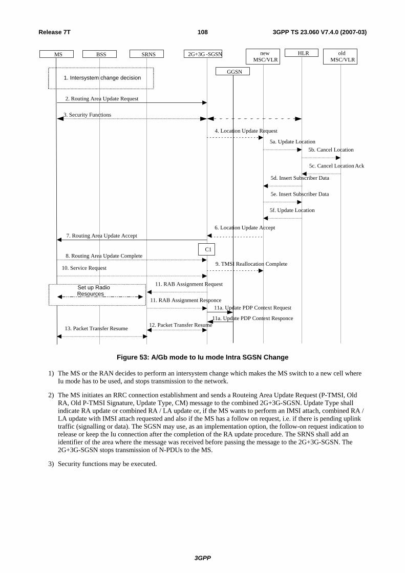
Release 7T 108 3GPP TS 23.060 V7.4.0 (2007-03)
3. Security Functions
MS BSS 2G+3G -SGSNSRNS
2. Routing Area Update Request
11. RAB Assignment Request
11. RAB Assignment Responce
13. Packet Transfer Resume
1. Intersystem change decision
12. Packet Transfer Resume
7. Routing Area Update Accept
8. Routing Area Update Complete
Set up RadioResources
C1
newMSC/VLR
HLR oldMSC/VLR
4. Location Update Request
5a. Update Location 5b. Cancel Location
5c. Cancel Location Ack
5d. Insert Subscriber Data
5e. Insert Subscriber Data
5f. Update Location
6. Location Update Accept
9. TMSI Reallocation Complete10. Service Request
GGSN
11a. Update PDP Context Request
11a. Update PDP Context Responce
Figure 53: A/Gb mode to Iu mode Intra SGSN Change
1) The MS or the RAN decides to perform an intersystem change which makes the MS switch to a new cell where Iu mode has to be used, and stops transmission to the network.
2) The MS initiates an RRC connection establishment and sends a Routeing Area Update Request (P-TMSI, Old RA, Old P-TMSI Signature, Update Type, CM) message to the combined 2G+3G-SGSN. Update Type shall indicate RA update or combined RA / LA update or, if the MS wants to perform an IMSI attach, combined RA / LA update with IMSI attach requested and also if the MS has a follow on request, i.e. if there is pending uplink traffic (signalling or data). The SGSN may use, as an implementation option, the follow-on request indication to release or keep the Iu connection after the completion of the RA update procedure. The SRNS shall add an identifier of the area where the message was received before passing the message to the 2G+3G-SGSN. The 2G+3G-SGSN stops transmission of N-PDUs to the MS.
3) Security functions may be executed.
3GPP

Release 7T 109 3GPP TS 23.060 V7.4.0 (2007-03)
4) If the association has to be established i.e. if Update Type indicates combined RA / LA update with IMSI attach requested, or if the LA changed with the routeing area update, the 2G+3G-SGSN sends a Location Update Request (new LAI, IMSI, SGSN Number, Location Update Type) to the VLR. Location Update Type shall indicate IMSI attach if Update Type in step 1 indicated combined RA / LA update with IMSI attach requested. Otherwise, Location Update Type shall indicate normal location update. When the SGSN does not provide functionality for the Intra Domain Connection of RAN Nodes to Multiple CN Nodes, the VLR number is derived from the RAI. When the SGSN provides functionality for Intra Domain Connection of RAN Nodes to Multiple CN Nodes, the SGSN uses the RAI and a hash value from the IMSI to determine the VLR number. The VLR creates or updates the association with the 2G+3G-SGSN by storing SGSN Number. In networks that support network sharing, the Location Update Request includes the identity of the selected core network operator if the SGSN has received this information from the RNS, as described in TS 23.251 [83].
5) If the subscriber data in the VLR is marked as not confirmed by the HLR, the new VLR informs the HLR. The HLR cancels the data in the old VLR and inserts subscriber data in the new VLR:
a) The new VLR sends an Update Location (new VLR) to the HLR.
b) The HLR cancels the data in the old VLR by sending Cancel Location (IMSI) to the old VLR.
c) The old VLR acknowledges with Cancel Location Ack (IMSI).
d) The HLR sends Insert Subscriber Data (IMSI, subscriber data) to the new VLR.
e) The new VLR acknowledges with Insert Subscriber Data Ack (IMSI).
f) The HLR responds with Update Location Ack (IMSI) to the new VLR.
6) The new VLR allocates a new VLR TMSI and responds with Location Update Accept (VLR TMSI) to the 2G+3G-SGSN. VLR TMSI is optional if the VLR has not changed.
7) The 2G+3G-SGSN validates the MS's presence in the new RA. If due to roaming restrictions or access restrictions the MS is not allowed to be attached in the RA, or if subscription checking fails, the 2G+3G-SGSN rejects the routeing area update with an appropriate cause. If the network supports the MOCN configuration for network sharing, the SGSN may, if the MS is not a 'Network Sharing Supporting MS', in this case decide to initiate redirection by sending a Reroute Command to the RNS, as described in TS 23.251 [83] instead of rejecting the routeing area update. If all checks are successful, the 2G+3G-SGSN updates MM and PDP contexts for the MS. A new P-TMSI may be allocated. A Routeing Area Update Accept (P-TMSI, P-TMSI Signature) message is returned to the MS. The 2G+3G-SGSN derives for this intersystem change the corresponding PDCP sequence numbers from the N-PDU sequence numbers stored in the SGSN PDP contexts by adding eight most significant bits "1". These PDCP sequence numbers are stored in the SGSN PDP contexts.
8) The MS acknowledges the new P-TMSI by returning a Routeing Area Update Complete message to the SGSN.
9) The 2G+3G-SGSN sends a TMSI Reallocation Complete message to the VLR if the MS confirms the VLR TMSI.
10) If the MS has pending uplink data or signalling, it shall send a Service Request (P-TMSI, RAI, CKSN, Service Type) message to the SGSN. Service Type specifies the requested service. Service Type shall indicate one of the following: Data or Signalling.
11) The 2G+3G-SGSN requests the SRNS to establish a radio access bearer by sending a RAB Assignment Request (RAB ID(s), QoS Profile(s), GTP-SNDs, GTP-SNUs, PDCP-SNUs) message to the SRNS. If Direct Tunnel is established the SGSN provides to the RNC the GGSN's Address for User Plane and TEID for uplink data. The PDCP sequence numbers are derived from the N-PDU sequence numbers and stored in the PDP contexts in step 7). The SRNS sends a Radio Bearer Setup Request (PDCP-SNUs) message to the MS. The MS responds with a Radio Bearer Setup Complete (PDCP-SNDs) message. The SRNS responds with a RAB Assignment Response message.
NOTE: The NSAPI value is carried in the RAB ID IE.
11a) If the SGSN established Direct Tunnel it shall send Update PDP Context Request to the GGSN(s) concerned and include the RNC's Address for User Plane, downlink TEID for data and DTI to instruct the GGSN(s) to apply Direct Tunnel specific error handling as described in clause 13.8. The GGSN(s) update the Address for User Plane and TEID for downlink data and return an Update PDP Context Response.
3GPP
Release 7T 110 3GPP TS 23.060 V7.4.0 (2007-03)
12) Traffic flow is resumed between the 2G+3G-SGSN and the SRNS. N-PDUs that were already sent to the MS in acknowledged mode SNDCP and that are not yet acknowledged by the MS are tunnelled by the 2G+3G-SGSN to the SRNS together with their related N-PDU number (SNDCP sequence number). No PDCP sequence numbers shall be indicated for these N-PDUs. The SRNS shall discard all N-PDUs with N-PDU sequence numbers older than the eight least significant bits of PDCP-SND received from the MS. Other N-PDUs shall be transmitted to the MS. The MS shall discard all N-PDUs with sequence numbers older than the eight least significant bits of the PDCP-SNU received from the SRNS. All other N-PDUs shall be transmitted to the SRNS. The SRNS negotiates with the MS for each radio bearer the use of lossless PDCP or not regardless whether the old 2G-SGSN used acknowledged or unacknowledged SNDCP for the related NSAPI or not.
13) The traffic flow is resumed between the SRNS and the MS.
The CAMEL procedure calls shall be performed, see referenced procedure in TS 23.078 [8b]:
C1) CAMEL_GPRS_Routeing_Area_Update_Session, CAMEL_PS_Notification and CAMEL_GPRS_Routeing_Area_Update_Context.
- The procedure CAMEL_GPRS_Routeing_Area_Update_Session is called once relative to the session. In Figure 53, the procedure returns as result "Continue".
- Then the procedures CAMEL_PS_Notification is called once relative to the session. The procedure returns as result "Continue".
- Then the procedure CAMEL_GPRS_Routeing_Area_Update_Context is called once per PDP context. In Figure 53, the procedure returns as result "Continue".
6.13.1.3 Selective RA Update
The MS shall use the following procedures when in STANDBY or PMM-IDLE state.
Note that upon expiry of the periodic RA update timer, the MS shall carry out the periodic routeing area update procedure.
6.13.1.3.1 Uplink Signalling or Data Transmission
In STANDBY or PMM-IDLE state the MS shall not perform an RA update procedure until uplink data or signalling information is to be sent from the MS.
If the MS is in the same mode (A/Gb mode or Iu mode) as when it last sent data or signalling, the procedures defined for that mode shall be followed. This shall be the sending of an LLC PDU in A/Gb mode, or for example sending of a Service Request message in Iu mode.
If the MS is in a different mode (A/Gb mode or Iu mode) as when it last sent data or signalling, the RA update procedure shall be performed before the sending of data or signalling. The RA update procedure needs not be performed if the signalling message is a power-off detach.
6.13.1.3.2 Downlink Signalling or Data Transmission
If the SGSN receives data for an MS in STANDBY or PMM-IDLE state, the SGSN shall page in the RA where the MS is located. This may include both A/Gb mode and Iu mode cells.
If the MS receives this page in the same mode (A/Gb mode or Iu mode)as when it last sent data or signalling, the procedures defined for that mode shall be followed. This shall be the sending of an LLC PDU in a cell where the MS has to use A/Gb mode or, for example, sending of a Service Request message in a cell where the MS has to use Iu mode.
If the MS receives this page in a different mode (A/Gb mode or Iu mode) as when it last sent data or signalling, the RA update procedure shall be performed. The SGSN shall accept this RAU as a valid response.
3GPP

Release 7T 111 3GPP TS 23.060 V7.4.0 (2007-03)
6.13.2 Inter-SGSN Inter-system Change
6.13.2.1 Iu mode to A/Gb mode Inter-SGSN Change
An inter-SGSN inter-system change from Iu mode to A/Gb mode takes place when an MS in PMM-IDLE or PMM-CONNECTED state changes from UTRAN or GERAN Iu mode to A/Gb mode and the A/Gb mode radio access node serving the MS is served by a different SGSN. In this case, the RA changes. Therefore, the MS shall initiate a A/Gb mode RA update procedure. The RA update procedure is either combined RA / LA update or only RA update. These RA update cases are illustrated in Figure 54. In the context of this specification, the terms RNS or RNC refer also to a GERAN BSS or BSC (respectively) when serving an MS in Iu mode.
A combined RA / LA update takes place in network operation mode I when the MS enters a new RA or when a GPRS-attached MS performs IMSI attach. The MS sends a Routeing Area Update Request indicating that an LA update may also need to be performed, in which case the SGSN forwards the LA update to the VLR. This concerns only idle mode (see TS 23.122 [7b]), as no combined RA / LA updates are performed during a CS connection.
NOTE: Direct Tunnel requires no additional functionality.
3GPP

Release 7T 112 3GPP TS 23.060 V7.4.0 (2007-03)
MS new2G-SGSN
HLRGGSNold3G-SGSN
2. Routing Area Update Request
10. Update PDP Context Request
10. Update PDP Context Response
11. Update GPRS Location
15. Update GPRS Location Ack
5. SGSN Context Response 6. Security Functions
19. Routing Area Update Accept
12. Cancel Location
12. Cancel Location Ack
14. Insert Subscriber Data Ack
14. Insert Subscriber Data
7. SGSN Context Acknowledge
BSS SRNS
3. SGSN Context Request
13. Iu Release Command
13. Iu Release Complete
8a. Forward Packets
9. Forward Packets
4. SRNS Context Request
4. SRNS Context Response
8. SRNS Data Forward Command
22. BSS Packet Flow Context Procedure
1. Intersystem changedecision
C3
C1
20. Routing Area Update Complete
newMSC/VLR
oldMSC/VLR
16. Location Update Request 17a. Update Location
17b. Cancel Location
17c. Cancel Location Ack 17d. Insert Subscriber Data
17e. Insert Subscriber Data Ack
17f. Update Location Ack 18. Location Update Accept
21. TMSI Reallocation Complete
C2
Figure 54: Iu mode to A/Gb mode Inter-SGSN Change
1) The MS or RAN decides to perform an inter-system change, which makes the MS switch to a new cell where A/Gb mode has to be used, and stops transmission to the network.
3GPP

Release 7T 113 3GPP TS 23.060 V7.4.0 (2007-03)
2) The MS sends a Routeing Area Update Request (old RAI, old P-TMSI Signature, Update Type, MS Network Capability) message to the new 2G-SGSN. Update Type shall indicate RA update or combined RA / LA update, or, if the MS wants to perform an IMSI attach, combined RA / LA update with IMSI attach requested. The BSS shall add the Cell Global Identity including the RAC and LAC of the cell where the message was received before passing the message to the new 2G-SGSN.
3) The new 2G-SGSN sends an SGSN Context Request (old RAI, TLLI, old P-TMSI Signature, New SGSN Address) message to the old 3G-SGSN to get the MM and PDP contexts for the MS. If the new SGSN provides functionality for Intra Domain Connection of RAN Nodes to Multiple CN Nodes, the new SGSN may derive the old SGSN from the old RAI and the old P-TMSI (or TLLI) and send the SGSN Context Request message to this old SGSN. Otherwise, the new SGSN derives the old SGSN from the old RAI. In any case the new SGSN will derive an SGSN that it believes is the old SGSN. This derived SGSN is itself the old SGSN, or it is associated with the same pool area as the actual old SGSN and it will determine the correct old SGSN from the P-TMSI (or TLLI) and relay the message to that actual old SGSN. The old 3G-SGSN validates the old P-TMSI Signature and responds with an appropriate error cause if it does not match the value stored in the old 3G-SGSN. If the received old P-TMSI Signature does not match the stored value, the security functions in the new 2G-SGSN should be initiated. If the security functions authenticate the MS correctly, the new 2G-SGSN shall send an SGSN Context Request (old RAI, TLLI, MS Validated, New SGSN Address) message to the old 3G-SGSN. MS Validated indicates that the new 2G-SGSN has authenticated the MS. If the old P-TMSI Signature was valid or if the new 2G-SGSN indicates that it has authenticated the MS correctly, the old 3G-SGSN starts a timer. If the MS is not known in the old 3G-SGSN, the old 3G-SGSN responds with an appropriate error cause.
4) If the MS is PMM-CONNECTED the old 3G-SGSN sends an SRNS Context Request (IMSI) message to the SRNS. Upon receipt of this message the SRNS buffers and stops sending downlink PDUs to the MS and returns an SRNS Context Response (GTP-SNDs, GTP-SNUs, PDCP-SNDs, PDCP-SNUs) message. The SRNS shall include for each PDP context the next in-sequence GTP sequence number to be sent to the MS and the GTP sequence number of the next uplink PDU to be tunnelled to the GGSN. For each active PDP context, which uses lossless PDCP, the SRNS also includes the uplink PDCP sequence number (PDCP-SNU) downlink PDCP sequence number (PDCP-SND). PDCP-SNU shall be the next in-sequence PDCP sequence number expected from the MS. PDCP-SND is the PDCP sequence number for the first downlink packet for which successful transmission has not been confirmed. The 3G-SGSN shall strip off the eight most significant bits of the passed PDCP sequence numbers, thus converting them to SNDCP N-PDU numbers and stores the N-PDU numbers in its PDP contexts..
5) The old 3G-SGSN responds with an SGSN Context Response (MM Context, PDP Contexts) message. For each PDP context the old 3G-SGSN shall include the GTP sequence number for the next uplink GTP PDU to be tunnelled to the GGSN and the next downlink GTP sequence number for the next in-sequence N-PDU to be sent to the MS. Each PDP Context also includes the SNDCP Send N-PDU Number (the value is 0) for the next in-sequence downlink N-PDU to be sent in SNDCP acknowledged mode to the MS and the SNDCP Receive N-PDU Number (= converted PDCP-SNU) for the next in-sequence uplink N-PDU to be received in SNDCP acknowledged mode from the MS. The new 3G-SGSN shall ignore the MS Network Capability contained in MM Context of SGSN Context Response only when it has previously received an MS Network Capability in the Routeing Area Request.
6) Security functions may be executed. If the SGSN Context Response message did not include IMEISV and the ADD function is supported by the new 2G-SGSN, then the IMEISV shall be retrieved from the MS.
7) The new 2G-SGSN sends an SGSN Context Acknowledge message to the old 3G-SGSN. This informs the old 3G-SGSN that the new 2G-SGSN is ready to receive data packets belonging to the activated PDP contexts. The old SGSN marks in its context that the MSC/VLR association and the information in the GGSNs and the HLR are invalid. This triggers the MSC/VLR, the GGSNs, and the HLR to be updated if the MS initiates a RA update procedure back to the old SGSN before completing the ongoing RA update procedure.
8) If the MS is in the PMM-CONNECTED state, the old 3G-SGSN sends an SRNS Data Forward Command (RAB ID, Transport Layer Address, Iu Transport Association) message to the SRNS. For each indicated RAB the SRNS starts duplicating and tunnelling the buffered GTP PDUs to the old 3G-SGSN. For each radio bearer which uses lossless PDCP the SRNS shall start tunnelling the GTP-PDUs related to transmitted but not yet acknowledged PDCP-PDUs to the old 3G-SGSN together with their related downlink PDCP sequence numbers. Upon receipt of the SRNS Data Forward Command message from the 3G-SGSN, the SRNS shall start the data-forwarding timer.
9) The old 3G-SGSN tunnels the GTP PDUs to the new 2G-SGSN. In the case of GTPv1, the conversion of PDCP sequence numbers to SNDCP sequence numbers (the eight most significant bits shall be stripped off) shall be
3GPP

Release 7T 114 3GPP TS 23.060 V7.4.0 (2007-03)
done in the new SGSN. No N-PDU sequence numbers shall be indicated for these N-PDUs. If GTPv0 is used between the SGSNs, the conversion of PDCP sequence numbers to SNDCP numbers shall be done in the old 3G-SGSN (by stripping off the eight most significant bits).
10) The new 2G-SGSN sends an Update PDP Context Request (new SGSN Address, TEID, QoS Negotiated, serving network identity, CGI/SAI, RAT type, CGI/SAI/RAI change support indication, NRSN) message to each GGSN concerned. The SGSN shall send the serving network identity to the GGSN. NRSN indicates SGSN support of the network requested bearer control. Each GGSN updates its PDP context fields and returns an Update PDP Context Response (TEID, Prohibit Payload Compression, APN Restriction, CGI/SAI/RAI change report required, BCM) message. The Prohibit Payload Compression indicates that the SGSN should negotiate no data compression for this PDP context.
11) The new 2G-SGSN informs the HLR of the change of SGSN by sending an Update GPRS Location (SGSN Number, SGSN Address, IMSI, IMEISV) message to the HLR. IMEISV is sent if the ADD function is supported.
12) The HLR sends a Cancel Location (IMSI) message to the old 3G-SGSN. The old 3G-SGSN acknowledges with a Cancel Location Ack (IMSI) message. The old 3G-SGSN removes the MM and PDP contexts if the timer described in step 3 is not running. If the timer is running, the MM and PDP contexts shall be removed when the timer expires.
13) When the MS is PMM-CONNECTED, the old 3G-SGSN sends an Iu Release Command message to the SRNS. When the RNC data-forwarding timer has expired, the SRNS responds with an Iu Release Complete message.
14) The HLR sends an Insert Subscriber Data (IMSI, GPRS Subscription Data) message to the new 2G-SGSN. The 2G-SGSN constructs an MM context and PDP contexts for the MS and returns an Insert Subscriber Data Ack (IMSI) message to the HLR.
15) The HLR acknowledges the Update GPRS Location by returning an Update GPRS Location Ack (IMSI) message to the new 2G-SGSN.
16) If the association has to be established i.e. if Update Type indicates combined RA / LA update with IMSI attach requested, or if the LA changed with the routeing area update, the new 2G-SGSN sends a Location Update Request (new LAI, IMSI, SGSN Number, Location Update Type) to the VLR. Location Update Type shall indicate IMSI attach if Update Type in step 1 indicated combined RA / LA update with IMSI attach requested. Otherwise, Location Update Type shall indicate normal location update. When the SGSN does not provide functionality for the Intra Domain Connection of RAN Nodes to Multiple CN Nodes, the VLR number is derived from the RAI. When the SGSN provides functionality for Intra Domain Connection of RAN Nodes to Multiple CN Nodes, the SGSN uses the RAI and a hash value from the IMSI to determine the VLR number. The 2G-SGSN starts the location update procedure towards the new MSC/VLR upon receipt of the first Insert Subscriber Data message from the HLR in step 14). The VLR creates or updates the association with the 2G-SGSN by storing SGSN Number.
17) If the subscriber data in the VLR is marked as not confirmed by the HLR, the new VLR informs the HLR. The HLR cancels the old VLR and inserts subscriber data in the new VLR:
a) The new VLR sends an Update Location (new VLR) to the HLR.
b) The HLR cancels the data in the old VLR by sending Cancel Location (IMSI) to the old VLR.
c) The old VLR acknowledges with Cancel Location Ack (IMSI).
d) The HLR sends Insert Subscriber Data (IMSI, subscriber data) to the new VLR.
e) The new VLR acknowledges with Insert Subscriber Data Ack (IMSI).
f) The HLR responds with Update Location Ack (IMSI) to the new VLR.
18) The new VLR allocates a new TMSI and responds with Location Update Accept (VLR TMSI) to the 2G-SGSN. VLR TMSI is optional if the VLR has not changed.
19) The new 2G-SGSN validates the MS's presence in the new RA. If due to roaming restrictions or access restrictions the MS is not allowed to be attached in the RA, or if subscription checking fails, the new 2G-SGSN rejects the routeing area update with an appropriate cause. If all checks are successful, the new 2G-SGSN constructs MM and PDP contexts for the MS. A logical link is established between the new 2G-SGSN and the
3GPP

Release 7T 115 3GPP TS 23.060 V7.4.0 (2007-03)
MS. 2G-SGSN initiates the establishment procedure. The new 2G-SGSN responds to the MS with a Routeing Area Update Accept (P-TMSI, P-TMSI Signature, Receive N-PDU Number (= converted PDCP-SNU) message. Receive N-PDU Number contains the acknowledgements for each NSAPI which used lossless PDCP before the start of the update procedure, thereby confirming all mobile-originated N-PDUs successfully transferred before the start of the update procedure. If Receive N-PDU Number confirms the reception of N-PDUs, the MS shall discard these N-PDUs.
20) The MS acknowledges the new P-TMSI by returning a Routeing Area Update Complete (Receive N-PDU Number (= converted PDCP-SND)) message to the SGSN. Receive N-PDU Number contains the acknowledgements for each lossless PDCP used by the MS before the start of the update procedure, thereby confirming all mobile-terminated N-PDUs successfully transferred before the start of the update procedure. If Receive N-PDU Number confirms the reception of N-PDUs that were forwarded from the old 3G-SGSN, the new 2G-SGSN shall discard these N-PDUs. The MS deducts Receive N-PDU number from PDCP-SND by stripping off the eight most significant bits. PDCP-SND is the PDCP sequence number for the next expected in-sequence downlink packet to be received in the MS per radio bearer, which used lossless PDCP. The new 2G-SGSN negotiates with the MS for each NSAPI the use of acknowledged or unacknowledged SNDCP regardless whether the SRNS used lossless PDCP or not.
21) The new 2G-SGSN sends TMSI Reallocation Complete message to the new VLR if the MS confirms the VLR TMSI.
22) The 2G-SGSN and the BSS may execute the BSS Packet Flow Context procedure.
If the new SGSN is unable to update the PDP context in one or more GGSNs, the new SGSN shall deactivate the corresponding PDP contexts as described in subclause "SGSN-initiated PDP Context Deactivation Procedure". This shall not cause the SGSN to reject the routeing area update.
The PDP Contexts shall be sent from old to new SGSN in a prioritized order, i.e. the most important PDP Context first in the SGSN Context Response message. (The prioritization method is implementation dependent, but should be based on the current activity).
The new SGSN shall determine the Maximum APN restriction based on the received APN Restriction of each PDP context from the GGSN and then store the new Maximum APN restriction value.
If the new SGSN is unable to support the same number of active PDP contexts as received from old SGSN, the new SGSN should use the prioritisation sent by old SGSN as input when deciding which PDP contexts to maintain active and which ones to delete. In any case, the new SGSN shall first update all contexts in one or more GGSNs and then deactivate the context(s) that it cannot maintain as described in subclause "SGSN-initiated PDP Context Deactivation Procedure". This shall not cause the SGSN to reject the routeing area update.
The CAMEL procedure calls shall be performed, see referenced procedures in TS 23.078 [8b]:
C1) CAMEL_GPRS_PDP_Context_Disconnection, CAMEL_GPRS_Detach and CAMEL_PS_Notification.
They are called in the following order:
- The CAMEL_GPRS_PDP_Context_Disconnection procedure is called several times: once per PDP context. The procedure returns as result "Continue".
- Then the CAMEL_GPRS_Detach procedure is called once. The procedure returns as result "Continue".
- Then the CAMEL_PS_Notification procedure is called once. The procedure returns as result "Continue".
C2) CAMEL_GPRS_Routeing_Area_Update_Session and CAMEL_PS_Notification.
They are called in the following order:
- The CAMEL_GPRS_Routeing_Area_Update_Session procedure is called. The procedure returns as result "Continue".
- Then the CAMEL_PS_Notification procedure is called. The procedure returns as result "Continue".
C3) CAMEL_GPRS_Routeing_Area_Update_Context.
This procedure is called several times once per PDP context. It returns as result "Continue".
3GPP

Release 7T 116 3GPP TS 23.060 V7.4.0 (2007-03)
6.13.2.2 A/Gb mode to Iu mode Inter-SGSN Change
The inter-system change from A/Gb mode to Iu mode takes place when a GPRS-attached MS changes from A/Gb mode to UTRAN or GERAN Iu mode and the new RAN node serving the MS is served by a different SGSN. In this case the RA changes. Therefore, the MS shall initiate a Iu mode RA update procedure by establishing an RRC connection and initiating the RA update procedure. The RA update procedure is either combined RA / LA update or only RA update, these RA update cases are illustrated in Figure 55. In the context of this specification, the terms RNS or RNC refer also to a GERAN BSS or BSC (respectively) when serving an MS in Iu mode.
If the network operates in mode I, then an MS, that is both PS-attached and CS-attached, shall perform the Combined RA / LA Update procedures. This concerns only idle mode (see TS 23.122 [7b]), as no combined RA / LA updates are performed during a CS connection.
3GPP

Release 7T 117 3GPP TS 23.060 V7.4.0 (2007-03)
MS new3G-SGSN
HLRGGSNold2G-SGSN
8. Update PDP Context Request
8. Update PDP Context Response
9. Update GPRS Location
12. Update GPRS Location Ack
2. Routeing Area Update Request
4. SGSN Context Response 5. Security Functions
16. Routeing Area Update Accept
10. Cancel Location
10. Cancel Location Ack
11. Insert Subscriber Data Ack 11. Insert Subscriber Data
17. Routeing Area Update Complete
6. SGSN Context Acknowledge
BSS SRNS
3. SGSN Context Request
20. RAB Assignment Request
20. RAB Assignment Response
7. Forward Packets
1. Intersystemchange decision
C3
C1
newMSC/VLR
oldMSC/VLR
13. Location Update Request 14a. Update Location
14b. Cancel Location
14b. Cancel Location Ack
14c. Insert Subscriber Data
14d. Insert Subscriber Data Ack
14e. Update Location Ack 15. Location Update Accept
18. TMSI Reallocation Complete
Set up RadioResources
19. Service Request
C2
20a. Update PDP Context Request
20a. Update PDP Context Responce
Figure 55: A/Gb mode to Iu mode Inter SGSN Change
1) The MS or RAN decides to perform an inter-system change, which makes the MS switch to a new cell where Iu mode has to be used, and stops transmission to the network.
3GPP

Release 7T 118 3GPP TS 23.060 V7.4.0 (2007-03)
2) The MS sends a Routeing Area Update Request (P-TMSI, old RAI, old P-TMSI Signature, Update Type, CM, MS Network Capability) message to the new 3G-SGSN. Update Type shall indicate RA update or combined RA / LA update, or, if the MS wants to perform an IMSI attach, combined RA / LA update with IMSI attach requested, and also if the MS has a follow-on request, i.e. if there is pending uplink traffic (signalling or data). The SGSN may use, as an implementation option, the follow-on request indication to release or keep the Iu connection after the completion of the RA update procedure. The SRNC shall add the Routeing Area Identity before forwarding the message to the 3G-SGSN. This RA identity corresponds to the RAI in the MM system information sent by the SRNC to the MS.
3) The new 3G-SGSN uses the old RAI received from the MS to derive the old 2G-SGSN address, and sends an SGSN Context Request (old RAI, old P-TMSI, New SGSN Address) message to the old 2G-SGSN to get the MM and PDP contexts for the MS. If the new SGSN provides functionality for Intra Domain Connection of RAN Nodes to Multiple CN Nodes, the new SGSN may derive the old SGSN from the old RAI and the old P-TMSI and send the SGSN Context Request message to this old SGSN. Otherwise, the new SGSN derives the old SGSN from the old RAI. In any case the new SGSN will derive an SGSN that it believes is the old SGSN. This derived SGSN is itself the old SGSN, or it is associated with the same pool area as the actual old SGSN and it will determine the correct old SGSN from the P-TMSI and relay the message to that actual old SGSN. The old 2G-SGSN validates the old P-TMSI Signature and responds with an appropriate error cause if it does not match the value stored in the old 2G-SGSN. If the received old P-TMSI Signature does not match the stored value, the old 2G-SGSN should initiate the security functions in the new 3G-SGSN. If the security functions authenticate the MS correctly, the new 3G-SGSN shall send an SGSN Context Request (old RAI, IMSI, MS Validated, New SGSN Address) message to the old 2G-SGSN. MS Validated indicates that the new 3G-SGSN has authenticated the MS. If the old P-TMSI Signature was valid or if the new 3G-SGSN indicates that it has authenticated the MS correctly, the old 2G-SGSN starts a timer and stops the transmission of N-PDUs to the MS.
4) The old 2G-SGSN responds with an SGSN Context Response (MM Context, PDP Contexts) message. Each PDP Context includes the GTP sequence number for the next downlink N-PDU to be sent to the MS and the GTP sequence number for the next uplink N-PDU to be tunnelled to the GGSN. Each PDP Context also includes the SNDCP Send N-PDU Number for the next downlink N-PDU to be sent in acknowledged mode SNDCP to the MS and the SNDCP Receive N-PDU Number for the next uplink N-PDU to be received in acknowledged mode SNDCP from the MS. The new 3G-SGSN derives the corresponding PDCP sequence numbers from these N-PDU sequence numbers by adding eight most significant bits "1". These PDCP sequence numbers are stored in the 3G-SGSN PDP contexts. The new 3G-SGSN shall ignore the MS Network Capability contained in MM Context of SGSN Context Response only when it has previously received an MS Network Capability in the Routeing Area Request.
5) Security functions may be executed. If the SGSN Context Response message did not include IMEISV and the ADD function is supported by the new 3G-SGSN, then the IMEISV shall be retrieved from the MS.
6) The new 3G-SGSN sends an SGSN Context Acknowledge message to the old 2G-SGSN. This informs the old 2G-SGSN that the new 3G-SGSN is ready to receive data packets belonging to the activated PDP contexts. The old SGSN marks in its context that the MSC/VLR association and the information in the GGSNs and the HLR are invalid. This triggers the MSC/VLR, the GGSNs, and the HLR to be updated if the MS initiates a routeing area update procedure back to the old SGSN before completing the ongoing routeing area update procedure.
7) The old 2G-SGSN duplicates the buffered N-PDUs and starts tunnelling them to the new 3G-SGSN. Additional N-PDUs received from the GGSN before the timer described in step 3 expires are also duplicated and tunnelled to the new 3G-SGSN. N-PDUs that were already sent to the MS in acknowledged mode SNDCP and that are not yet acknowledged by the MS are tunnelled together with their related SNDCP N-PDU sequence number. No PDCP sequence numbers shall be indicated for these N-PDUs. No N-PDUs shall be forwarded to the new 3G-SGSN after expiry of the timer described in step 3.
8) The new 3G-SGSN sends an Update PDP Context Request (new SGSN Address, TEID, QoS Negotiated, serving network identity, CGI/SAI, RAT type, CGI/SAI/RAI change support indication, NRSN) message to each GGSN concerned. The SGSN shall send the serving network identity to the GGSN. NRSN indicates SGSN support of the network requested bearer control. Each GGSN updates its PDP context fields and returns an Update PDP Context Response (TEID, Prohibit Payload Compression, APN Restriction, CGI/SAI/RAI change report required, BCM) message. The Prohibit Payload Compression indicates that the SGSN should negotiate no data compression for this PDP context.
9) The new 3G-SGSN informs the HLR of the change of SGSN by sending an Update GPRS Location (SGSN Number, SGSN Address, IMSI, IMEISV) message to the HLR. IMEISV is sent if the ADD function is supported.
3GPP

Release 7T 119 3GPP TS 23.060 V7.4.0 (2007-03)
10) The HLR sends a Cancel Location (IMSI, Cancellation Type) message to the old 2G-SGSN. The old 2G-SGSN removes the MM and PDP contexts if the timer described in step 3 is not running. If the timer is running, the MM and PDP contexts are removed when the timer expires. The old 2G-SGSN acknowledges with a Cancel Location Ack (IMSI) message.
11) The HLR sends an Insert Subscriber Data (IMSI, GPRS Subscription Data) message to the new 3G-SGSN. The 3G-SGSN constructs an MM context for the MS and returns an Insert Subscriber Data Ack (IMSI) message to the HLR.
12) The HLR acknowledges the Update GPRS Location by returning an Update GPRS Location Ack (IMSI) message to the new 3G-SGSN.
13) If the association has to be established, if Update Type indicates combined RA / LA update with IMSI attach requested, or if the LA changed with the routeing area update, the new SGSN sends a Location Update Request (new LAI, IMSI, SGSN Number, Location Update Type) to the VLR. Location Update Type shall indicate IMSI attach if Update Type in step 1 indicated combined RA / LA update with IMSI attach requested. Otherwise, Location Update Type shall indicate normal location update. When the SGSN does not provide functionality for the Intra Domain Connection of RAN Nodes to Multiple CN Nodes, the VLR number is derived from the RAI. When the SGSN provides functionality for Intra Domain Connection of RAN Nodes to Multiple CN Nodes, the SGSN uses the RAI and a hash value from the IMSI to determine the VLR number. The 3G-SGSN starts the location update procedure towards the new MSC/VLR upon receipt of the first Insert Subscriber Data message from the HLR in step 12). The VLR creates or updates the association with the 3G-SGSN by storing SGSN Number. In networks that support network sharing, the Location Update Request includes the identity of the selected core network operator if the new 3G-SGSN has received this information from the RNS, as described in TS 23.251 [83].
14) If the subscriber data in the VLR is marked as not confirmed by the HLR, the new VLR informs the HLR. The HLR cancels the old VLR and inserts subscriber data in the new VLR:
a) The new VLR sends an Update Location (new VLR) to the HLR.
b) The HLR cancels the data in the old VLR by sending Cancel Location (IMSI) to the old VLR.
c) The old VLR acknowledges with Cancel Location Ack (IMSI).
d) The HLR sends Insert Subscriber Data (IMSI, subscriber data) to the new VLR.
e) The new VLR acknowledges with Insert Subscriber Data Ack (IMSI).
f) The HLR responds with Update Location Ack (IMSI) to the new VLR.
15) The new VLR allocates a new TMSI and responds with Location Update Accept (VLR TMSI) to the 3G-SGSN. VLR TMSI is optional if the VLR has not changed.
16) The new 3G-SGSN validate the MS's presence in the new RA. If due to roaming restrictions or access restrictions the MS is not allowed to be attached in the RA, or if subscription checking fails, the new 3G-SGSN rejects the routeing area update with an appropriate cause. If the network supports the MOCN configuration for network sharing, the SGSN may, if the MS is not a 'Network Sharing Supporting MS', in this case decide to initiate redirection by sending a Reroute Command to the RNS, as described in TS 23.251 [83] instead of rejecting the roueting area update. If all checks are successful, the new 3G-SGSN constructs MM and PDP contexts for the MS. The new 3G-SGSN responds to the MS with a Routeing Area Update Accept (P-TMSI, P-TMSI signature) message.
17) The MS acknowledges the new P-TMSI by returning a Routeing Area Update Complete message to the SGSN.
18) The new 3G-SGSN sends TMSI Reallocation Complete message to the new VLR, if the MS confirms the VLR TMSI.
19) If the MS has uplink data or signalling pending it shall send a Service Request (P-TMSI, RAI, CKSN, Service Type) message to the SGSN. Service Type specifies the requested service. Service Type shall indicate one of the following: Data or Signalling.
20) If the MS has sent the Service Request, the new 3G-SGSN requests the SRNS to establish a radio access bearer by sending a RAB Assignment Request (RAB ID(s), QoS Profile(s), GTP-SNDs, GTP-SNUs, PDCP-SNUs) message to the SRNS. If Direct Tunnel is established the SGSN provides to the RNC the GGSN's Address for
3GPP

Release 7T 120 3GPP TS 23.060 V7.4.0 (2007-03)
User Plane and TEID for uplink data. The PDCP sequence numbers are derived from the N-PDU sequence numbers in step 4) and stored in the SGSN PDP contexts. The SRNS sends a Radio Bearer Setup Request (PDCP-SNUs) message to the MS. The MS responds with a Radio Bearer Setup Complete (PDCP-SNDs) message. The MS deducts PDCP-SND from its Receive N-PDU Number by adding eight most significant bits "1". The SRNS responds with a RAB Assignment Response message. The SRNS shall discard all N-PDUs tunnelled from the SGSN with N-PDU sequence numbers older than the eight least significant bits of the PDCP-SNDs received from the MS. Other N-PDUs shall be transmitted to the MS. The MS shall discard all N-PDUs with SNDCP sequence numbers older than the eight least significant bits of the PDCP-SNUs received from the SRNS. Other N-PDUs shall be transmitted to the SRNS. The SRNS negotiates with the MS for each radio bearer the use of lossless PDCP or not regardless whether the old 2G-SGSN used acknowledged or unacknowledged SNDCP for the related NSAPI or not.
20a) If the SGSN established Direct Tunnel in step 20) it shall send Update PDP Context Request to the GGSN(s) concerned and include the RNC's Address for User Plane, downlink TEID for data and DTI to instruct the GGSN to apply Direct Tunnel specific error handling as described in clause 13.8. The GGSN(s) update the Address for User Plane and TEID for downlink data and return an Update PDP Context Response.
NOTE 1: The NSAPI value is carried in the RAB ID IE.
NOTE 2: The new SGSN may initiate RAB establishment after execution of the security functions (step 5), or wait until completion of the RA update procedure. For the MS, RAB establishment may occur anytime after the RA update request is sent (step 2).
If the new SGSN is unable to update the PDP context in one or more GGSNs, the new SGSN shall deactivate the corresponding PDP contexts as described in subclause "SGSN-initiated PDP Context Deactivation Procedure". This shall not cause the SGSN to reject the routeing area update.
The PDP Contexts shall be sent from old to new SGSN in a prioritized order, i.e. the most important PDP Context first in the SGSN Context Response message. (The prioritization method is implementation dependent, but should be based on the current activity).
The new SGSN shall determine the Maximum APN restriction based on the received APN Restriction of each PDP context from the GGSN and then store the new Maximum APN restriction value.
If the new SGSN is unable to support the same number of active PDP contexts as received from old SGSN, the new SGSN should use the prioritisation sent by old SGSN as input when deciding which PDP contexts to maintain active and which ones to delete. In any case, the new SGSN shall first update all contexts in one or more GGSNs and then deactivate the context(s) that it cannot maintain as described in subclause "SGSN-initiated PDP Context Deactivation Procedure". This shall not cause the SGSN to reject the routeing area update.
The CAMEL procedure calls shall be performed, see referenced procedures in TS 23.078 [8b]:
C1) CAMEL_GPRS_PDP_Context_Disconnection, CAMEL_GPRS_Detach and CAMEL_PS_Notification.
They are called in the following order:
- The CAMEL_GPRS_PDP_Context_Disconnection procedure is called several times: once per PDP context. The procedure returns as result "Continue".
- Then the CAMEL_GPRS_Detach procedure is called once. It returns as result "Continue".
- Then the CAMEL_PS_Notification procedure is called once. It returns as result "Continue".
C2) CAMEL_GPRS_Routeing_Area_Update_Session and CAMEL_PS_Notification.
They are called in the following order:
- The CAMEL_GPRS_Routeing_Area_Update_Session procedure is called. The procedure returns as result "Continue".
- Then the CAMEL_PS_Notification procedure is called. The procedure returns as result "Continue".
C3) CAMEL_GPRS_Routeing_Area_Update_Context
This procedure is called several times: once per PDP context. It returns as result "Continue".
3GPP

Release 7T 121 3GPP TS 23.060 V7.4.0 (2007-03)
6.14 Classmark Handling To support efficient radio interface usage in GPRS, the MS classmark is handled differently for SGSN-based services than for MSC-based services. In particular, the classmark information is sent in MM and Iu mode RRC messages to the network and stored in the network as long as the MS is attached, avoiding redundant classmark retransmissions over the radio interface. This is sometimes called the "idle-mode classmark" principle.
In order to allow introduction of new radio access technologies in the future, the MS classmark is split into two distinct and independent information elements, the radio access classmark, and the MS network capability. The radio access classmark is split into two information elements, the MS radio access capability (A/Gb mode) and the UE capability (Iu mode). The MS network capability IE shall be common for A/Gb mode and Iu mode.
Details of classmark handling during PS Handover are defined in TS 24.008 [13] and TS 44.060 [77] for A/Gb mode and TS 25.331 [52] for Iu mode.
6.14.1 Radio Access Classmark The MS shall send the MS radio access capability in the GPRS Attach Request message to the SGSN regardless, if the MS is about to attach to A/Gb mode or to Iu mode network, as defined in TS 24.008 [13].
6.14.1.1 MS Radio Access Capability (A/Gb mode)
The MS radio access capability information element contains the A/Gb mode radio capabilities of the MS (e.g. multislot capability, power class), and more generally all the information that should be known by the BSS in order to handle radio resources for that MS.
The MS radio access capability is a container for a multiplicity of radio access technology-dependent information, i.e. within the MS radio access capability there are independent sub-fields for various technologies such as GSM 900 and GSM 1800. The coding shall allow a BSS to extract only the sub-fields relevant to it without interpreting the other sub-fields. This ensures that the MS radio access capability does not need to be interpreted by the NSS, and the full MS radio access capability is always sent by the MS to the SGSN, and thereafter provided to the BSS irrespective of the actual BSS capabilities.
The SGSN shall provide the MS radio access capability as an information element on the Gb interface. It is the responsibility of the SGSN to provide the BSS with the most recent MS radio access capability received from the MS. The MS radio access capability information element can be included in a downlink transfer request, or be sent in a specific message that updates the MS radio access capability information in the BSS. The BSS may at any time request the MS radio access capability for a given MS to be transmitted from the SGSN to the BSS.
Together with the MS radio access capability, the SGSN shall provide the IMSI of the MS when this is known. For a BSS supporting DTM, the IMSI is stored at the BSS and used for radio resource co-ordination; e.g. for a DTM MS.
A specific optimisation allows the BSS to receive a reduced MS radio access capability at initial access directly from the MS. This enables the BSS not to wait for the full MS radio access capability to be provided by the SGSN, and is therefore quicker for the initial MS-originated transmission. The reduced MS radio access capability can be carried in several RR messages depending on the access method, e.g. in the initial random access message, or in the first uplink radio block. Details are provided in TS 24.008 [13] and TS 44.060 [77].
At inter-system change the MS radio access capability shall be sent to the SGSN in the Routeing Area Update Request message, as specified in TS 24.008 [13]. The SGSN then provides the BSS with the radio capabilities.
6.14.1.2 UE Capability (Iu mode)
The UE capability information element contains all the radio capabilities of the MS (power control, code resource, UE mode, ciphering, PDCP capabilities, etc.) that the RNC has to know in order to handle radio resources for this MS.
The MS sends the UE capability information element to the serving RNC upon RRC connection establishment, and the RNC stores it. This is done before the Attach Request or Routeing Area Update Request message is sent.
NOTE: In Iu mode, only the RNC handles the radio capabilities.
3GPP

Release 7T 122 3GPP TS 23.060 V7.4.0 (2007-03)
At SRNC relocation the source RNC sends the UE capability transparently through the core network to the target RNC. If the RNC has not received the UE capability information it can request the MS to send the information.
At inter-system change the UE capability is transferred from the MS to the serving RNC on RRC connection establishment before the Routeing Area Update Request message is sent.
Details are provided in TS 25.331 [52] and TS 25.413 [56b].
6.14.2 MS Network Capability The MS network capability contains non radio-related capabilities, e.g. the GSM GPRS ciphering, UMTS authentication, and TI extension capabilities. In the coding of the information element certain capabilities may be grouped together in a single indicator. The SGSN stores the MS network capability, which is used both by the local SGSN and for transfer to the new SGSN for any type of inter SGSN RA updates. To avoid interoperability problems when roaming between A/Gb mode and Iu mode, the MS network capability shall be included in the routeing area update request sent by the MS. At inter-SGSN RA update, the network shall use this MS Network Capability and ignore the same IE received in MM Context from the old SGSN.
7 Network Management Functionality The Network Management function provides mechanisms to support O&M functions related to GPRS.
8 Radio Resource Functionality
8.1 Radio Resource Functionality (A/Gb mode)
8.1.1 Cell Selection and Reselection An MS (in any mode of operation - A, B, or C) cannot camp on more than one cell. If the MS is in idle mode, see TS 23.122 [7b], it shall use cell selection and reselection procedures as described in TS 43.064 [11] and specified in TS 23.122 [7b] and TS 45.008 [16b].
8.1.2 Discontinuous Reception In A/Gb mode an MS may use discontinuous reception (DRX) or not. If using DRX, the MS shall also be able to specify other DRX parameters that indicate the delay for the network to send a page request or a channel assignment to the MS (see TS 43.064 [11]).
The DRX parameters shall be indicated by the MS in the attach procedure. The SGSN shall then send these parameters in each page request to the BSS that uses this information and the IMSI to calculate the correct paging group.
DRX usage is independent of the MM states IDLE, STANDBY and READY. When a GPRS MS in READY state uses DRX, DRX has to be considered when assigning a packet data channel for downlink transfer. The SGSN shall therefore indicate the DRX parameters for the MS in all packet transmission requests to the BSS.
In A/Gb mode an MS shall not apply DRX in READY state during the GPRS attach and routeing area update procedures.
8.1.3 Radio Resource Management A/Gb mode Radio Resource Management functions are defined in TS 24.007 [12]. The radio interface layer 3 protocol is specified in TS 24.008 [13].
3GPP

Release 7T 123 3GPP TS 23.060 V7.4.0 (2007-03)
8.1.3.1 Layer Functions
GPRS radio resource management procedures are required for the following functions:
- allocation and release of physical resources (i.e. timeslots) associated with a GPRS channel;
- monitoring GPRS channel utilisation to detect under-utilised or congested GPRS channels;
- initiating congestion control procedures; and
- distribution of GPRS channel configuration information for broadcasting to the MSs.
The radio resource management features that are required for PS handover are detailed in TS 43.129 [87].
8.1.3.2 Model of Operation
8.1.3.2.1 Dynamic Allocation of Radio Resources
AnA/Gb mode cell may or may not support GPRS.
A cell supporting GPRS may have GPRS radio resources allocated at a given instance. If no GPRS radio resources are allocated, an MS can request allocation of such resources. MSs may then use these radio resources. The PLMN may dynamically increase, to a PLMN operator-defined maximum, or, decrease to an operator-defined minimum, the radio resources allocated.
The network broadcasts GPRS system information on the common control channels.
A/Gb mode radio resources are dynamically shared between GPRS and CS domain services.
8.1.4 Paging for GPRS Downlink Transfer An MS in STANDBY state is paged by the SGSN before a downlink transfer to that MS. The paging procedure shall move the MM state to READY to allow the SGSN to forward downlink data to the radio resource. Therefore, any uplink data from the MS that moves the MM context at the SGSN to READY state is a valid response to paging.
The SGSN supervises the paging procedure with a timer. If the SGSN receives no response from the MS to the Paging Request message, it shall repeat the paging. The repetition strategy is implementation dependent.
The MS shall accept pages also in READY state if no radio resource is assigned. This supports recovery from inconsistent MM states in the MS and the SGSN.
The GPRS Paging procedure is illustrated in Figure 56.
5. Any LLC Frame 4. Any LLC Frame
3. GPRS Paging Request
2. Paging Request 1. PDP PDU
MS BSS SGSN
Figure 56: GPRS Paging Procedure
1) The SGSN receives a downlink PDP PDU for an MS in STANDBY state. Downlink signalling to a STANDBY state MS initiates paging as well.
2) The SGSN sends a BSSGP Paging Request (IMSI, P-TMSI, Area, Channel Needed, QoS, DRX Parameters) message to the BSS serving the MS. IMSI is needed by the BSS in order to calculate the MS paging group. P-TMSI is the identifier by which the MS is paged. Area indicates the routeing area in which the MS is paged. Channel Needed indicates GPRS paging. QoS is the negotiated QoS for the PDP context that initiates the paging
3GPP

Release 7T 124 3GPP TS 23.060 V7.4.0 (2007-03)
procedure, and indicates the priority of this Paging Request relative to other Paging Request messages buffered in the BSS. DRX Parameters indicates whether the MS uses discontinuous reception or not. If the MS uses discontinuous reception, DRX Parameters also indicate when the MS is in a non-sleep mode able to receive paging requests.
3) The BSS pages the MS with one Paging Request (P-TMSI, Channel Needed) message in each cell belonging to the addressed routeing area. This is described in TS 43.064 [11].
4) Upon receipt of a GPRS Paging Request message, the MS shall respond with either any single valid LLC frame (e.g. a Receive Ready or Information frame) that implicitly is interpreted as a page response message by the SGSN. The MS shall not use the LLC NULL frame as a page response. When responding, the MS changes MM state to READY. The Packet Channel Request precedes the response and Packet Immediate Assignment procedures as described in TS 43.064 [11].
5) Upon reception of the LLC frame, the BSS adds the Cell Global Identity including the RAC and LAC of the cell and sends the LLC frame to the SGSN. The SGSN shall then consider the LLC frame to be an implicit paging response message and stop the paging response timer.
8.1.5 RAN Information Management (RIM) procedures
8.1.5.1 General
The RAN Information Management (RIM) procedures provide a generic mechanism for the exchange of arbitrary information between applications belonging to the RAN nodes. The RAN information is transferred via the SGSN core network node(s). In order to make the RAN information transparent for the Core Network, the RAN information is included in a RIM container that shall not be interpreted by the Core Network nodes.
The RIM procedures are optional both in the RAN node and in the SGSN. For the Gb interface the use of RIM procedures is negotiated at start/restart of the Gb link. For the Iu interface there is no negotiation of using RIM procedures or not at Iu link start/restart.
The RAN information is transferred in RIM containers from the source RAN node to the destination RAN node by use of messages. Each message carrying the RIM container is routed and relayed independently by the SGSN(s). Any relation between messages is transparent for the SGSN, i.e. a request/response exchange between RIM applications, for example, is routed and relayed as two independent messages by the SGSN.
The interfaces which will be used are the Gb (BSSGP) , the Iu (RANAP) and the Gn (GTP) interfaces. The RAN information in the RIM container shall be transparent for the Core Network. An SGSN supporting the RIM procedures provides addressing, routeing and relay functions.
8.1.5.2 Addressing, routeing and relaying
8.1.5.2.1 Addressing
All the messages used for the exchange of RAN information contain the addresses of the source and destination RAN nodes. A BSS is addressed by Routeing Area Identity (RAI) + Cell Identity (CI) of one of its cells. An RNC is addressed by Global RNC-Id.
8.1.5.2.2 Routeing
The following description applies to all the messages used for the exchange of RAN information.
The source RAN node sends a message to its SGSN including the source and destination addresses. An RNC sends in addition a RIM routing address, which is a copy of the destination address. From the destination address or from the RIM routing address, the SGSN shall decide whether or not it is connected to the destination RAN node.
If the SGSN is not connected to the destination RAN node, then it shall use the destination address or the RIM routing address to route the message encapsulated in a GTP message to the correct SGSN via the Gn interface. If the destination address or RIM routing address identifies an RNC the SGSN includes the RIM routing address in the GTP message. If the SGSN received the message from a BSC it copies the destination address from the message into the RIM routing address.
3GPP

Release 7T 125 3GPP TS 23.060 V7.4.0 (2007-03)
The SGSN connected to the destination RAN node decides which RAN node to send the message to based on the destination address or on the RIM routing address.
8.1.5.2.3 Relaying
The SGSN performs relaying between BSSGP messages, RANAP messages and GTP messages as described in TS 48.018 [78], TS 25.413 [56b] and TS 29.060 [26].
8.1.5.3 Void
8.1.5.4 Void
8.1.5.5 Applications using the RIM Procedures
The RAN node applications, which use the RIM procedures, are fully transparent for the SGSN. These applications are described in RAN specifications. An example is the Network Assisted Cell Change described in TS 48.018 [78] and TS 25.413 [56b].
8.1.6 BSS Paging Co-ordination In Network Operation Mode II and III, paging from one CN domain is done independently from the state of the MS in the other CN domain, i.e. no paging co-ordination on core network level is done.
It is, however, possible to do paging co-ordination on BSS level in these cases. This means that for each paging request received from one CN domain, the BSC determines whether the MS is engaged with the other CN domain or not. In order to achieve this, the context that is prepared within the BSC for an MS engaged with one of the CN domains must contain the IMSI, which is the common MS identity for the two CN domains.
If the BSC determines that the MS is engaged with the PS domain, the CS paging will be done on a packet data channel for the MS in question.
If the BSC determines that the MS is engaged with the CS domain, the PS paging (packet notification) will be done on a CS dedicated channel for the MS in question.
If no context is found for the MS, "normal CS paging" is performed on the CCCH paging channel and "normal PS paging" is performed on the CCCH paging channel or the packet paging channel, as applicable.
If BSS paging co-ordination for CS paging is active in a cell or not, shall be indicated as system information to the MSs. For proper operation, the mode should be the same in each cell of a routeing area.
BSS paging co-ordination for PS paging shall always be active in a cell where DTM is supported and is applicable to MSs supporting DTM.
8.2 Radio Resource Functionality (Iu mode)
8.2.1 Radio Resource Management UTRAN functions are defined in TS 25.401 [53]. The radio interface protocol architecture is specified in TS 25.301 [50], and the Radio Resource Control protocol is specified in TS 25.331 [52]. TS 43.051 [74] contains an overall description of GSM/EDGE Radio Access Network.
In the context of this specification, the term URA refers also to GRA (GERAN Registration Area) when the RAN serving an MS in Iu mode is a GERAN.
3GPP

Release 7T 126 3GPP TS 23.060 V7.4.0 (2007-03)
8.2.2 RRC State Machine The RRC state machine is a description model of how the MS and the Iu mode RAN co-operate regarding RRC functionality. The RRC state describes the MS state in the Iu mode RAN. This clause contains a brief description of the RRC state machine, for more information see TS 25.303 [51].
The RRC state machine exists as two peer entities, one in the MS and one in the Iu mode RAN. Apart from transient situations and error cases the two peer entities are synchronised. Figure 57 illustrates the main modes and states of the RRC state machine.
Idle mode
CellConnected
RRCconnectionestablishment
URAConnected
RRCconnectionrelease
Enter URAconnected state
Enter cellconnected state
Connected mode
Figure 57: RRC Modes, Main RRC States and Main Mode and State Transition
RRC Idle mode: In the Idle mode there is no connection established between the MS and the Iu mode RAN. There is no signalling between RAN and the MS except for system information that is sent from RAN on a broadcast channel to the MS. The MS can also receive paging messages with a CN identity on the PCH. There is no information of the MS stored in RAN in this mode.
RRC Connected mode: In the Connected mode the main states are Cell Connected state and URA Connected state. In this mode there is one RNC/BSC that is acting as serving RNC/BSC, and an RRC connection is established between the MS and this SRNC/SBSC.
- When the MS position is known at the cell level, the MS is in the Cell Connected state. When in Cell Connected state, the RRC connection mobility is handled by handover and cell update procedures.
- When the MS position is known at the URA level, the MS is in the URA Connected state. URA updating procedures provide the mobility functionality in this state. No dedicated radio resources are used in the URA Connected state.
8.2.3 Discontinuous Reception An MS can set the DRX cycle length that is specific to the PS domain. TS 25.304 [51b] describes how the MS shall select which DRX cycle length to use with respect to DRX cycle length requirements set by the RAN, CN PS domain and CN CS domain.
The DRX parameter information shall be indicated by the MS in the attach procedure and when changing from A/Gb mode to Iu mode also in the routeing area update procedure. The SGSN shall then in each page request send these parameters to the RNC/BSC that uses this information, and the IMSI, to calculate the correct paging group.
At inter-SGSN RA update, the network shall use the DRX IE received from the MS in the routeing area update request message and ignore the same IE received in MM Context from the old SGSN.
8.2.4 Paging Initiated by CN A CN node requests paging only for MSs in CMM-IDLE state or PMM-IDLE state. In the separate CN architecture, paging from a CN node is done independently from the state of the MS in the other CN service domain.
3GPP

Release 7T 127 3GPP TS 23.060 V7.4.0 (2007-03)
In the context of this specification, the terms RNS or RNC refer also to a GERAN BSS or BSC (respectively) when serving an MS in Iu mode.
In this alternative with paging co-ordination in the RAN, the MS does not need to listen to the PCH (Paging Channel) in the RRC Connected mode, at least not when MS is allocated a dedicated channel.
For each paging request received from a CN node, the RNC determines whether the MS has an established RRC connection or not. In order to achieve this, the context that is prepared within the SRNC for MS in RRC Connected mode must contain the IMSI, which is the common MS identity for the two CN domains.
If no context is found for the MS, "normal PCH paging" is performed. The paging message is transferred on the paging channel, and it includes the MS paging identity received from the CN and a CN service domain type indication.
If a context is found, a "CN paging message" is transferred using the existing RRC connection. This message includes a CN service domain type indication. If, potentially after repetition, this transfer is unsuccessful and if the CS domain originally triggered the paging, the RNC should decide whether to attempt "normal PCH paging" as described in sub-clause "Unsynchronous states in the UE and the UTRAN".
8.2.4.1 PS Paging Initiated by 3G-SGSN without RRC Connection for CS
4. Service Request
4. Service Request
3. Paging Type12. Paging
MS RNS MSC/VLR
3G-SGSN
1. PDP PDU orDownlink signalling
Figure 58: PS Paging Without RRC Connection for CS
1) The 3G-SGSN receives a PDP PDU or downlink signalling for an MS in PMM Idle state.
2) The 3G-SGSN sends a RANAP Paging (IMSI, P-TMSI, Area, CN Domain Indicator, DRX parameters) message to each RNS belonging to the routeing area in which the MS is located. IMSI is needed by the RNS in order to calculate the MS paging group, and to identify the paged MS. If 3G-SGSN assigned the P-TMSI to the MS, P-TMSI is also included. Area indicates the routeing area in which the MS is paged. CN Domain Indicator indicates which domain (MSC or 3G-SGSN) initiated the paging message, and it represents "SGSN" in this case. DRX Parameters indicates whether or not the MS uses discontinuous reception and the DRX cycle length.
3) The RNS controls whether the MS has an established RRC connection or not. In this case, MS has no RRC connection, so a "normal PCH paging" is performed. Paging Type 1(IMSI or P-TMSI, Paging originator, CN domain ID) is transferred on the Paging channel, IMSI or P-TMSI identifies the MS. Paging originator indicates whether this is core network originated paging or RAN originated paging, so it represents "CN" in this case. And CN domain ID indicates whether this paging message is for CS service or PS service, so it represents "PS" in this case.
4) The paging request triggers the Service Request procedures in the MS. The service request procedures are described in clause "Service Request Procedure (Iu mode)".
3GPP

Release 7T 128 3GPP TS 23.060 V7.4.0 (2007-03)
Optionally, 3G-SGSN may include "Non Searching Indication" in RANAP Paging message in this case. If a "Non Searching Indication" parameter is present, the RNC will not search the established RRC connection, and just initiate "normal PCH paging".
8.2.4.2 PS Paging Initiated by 3G-SGSN With RRC Connection for CS
4. Service Request
4. Service Request
3. Paging Type22. Paging
MS RNS MSC/VLR
3G-SGSN
Connection Established
1. PDP PDU orDownlink signalling
Figure 59: PS Paging With RRC Connection for CS
1) The 3G-SGSN receives a PDP PDU or downlink signalling for an MS in PMM Idle state.
2) The 3G-SGSN sends a RANAP Paging (IMSI, P-TMSI, Area, CN Domain Indicator, DRX parameters) message to each RNS belonging to the routeing area in which the MS is located. IMSI is needed by the RNS in order to calculate the MS paging group. If 3G-SGSN assigned the P-TMSI to the MS, P-TMSI is included, and it identifies the MS is paged. Area indicates the routeing area in which the MS is paged. CN Domain Indicator indicates to which domain (MSC or 3G-SGSN) the paging was initiated, and it represents "3G-SGSN" in this case. DRX Parameters indicates whether or not the MS uses discontinuous reception and the DRX cycle length.
3) The RNS controls whether the MS has an established RRC connection or not. In this case, MS has an established RRC connection for CS service, so RNS sends an RRC Paging Type 2 (CN domain ID) message to the MS on established RRC connection. CN Domain ID indicates to which domain (CS or PS) the paging shall be directed, so it represents "PS" in this case.
4) The paging request triggers the Service Request procedures in the MS. The service request procedures are described in clause "Service Request Procedure (Iu mode)".
8.2.5 Paging Initiated by RAN An MS in RRC URA/GRA connected state is paged by the RAN before a downlink transfer to that MS. The URA/GRA paging procedure shall move the RRC state to Cell Connected to allow the RAN to forward downlink data or signalling message to the radio resource. Therefore, the RRC: Cell Update message from the MS that moves the RRC State at the RAN to Cell Connected state is a valid response to URA/GRA paging.
The RAN supervises the paging procedure with a timer. If the RAN receives no response from the MS to the URA or GRA Paging Request message, it shall repeat the paging. The repetition strategy is implementation dependent. If it is unsuccessful and if the paging was originally triggered by the CS domain, it is the RNC's responsibility to recover this situation by following the "normal PCH paging" mechanism (see sub-clause "Paging Initiated by CN"). For more information see TS 25.303 [51].
The URA/GRA Paging procedure is illustrated in Figure 60.
3GPP

Release 7T 129 3GPP TS 23.060 V7.4.0 (2007-03)
MS RAN
1. PDP PDU or RANAP
3. Cell Update
2. Paging Type1
Figure 60: URA/GRA Paging Procedure
1) The RAN receives a downlink PDP PDU for an MS in RRC URA/GRA connected state. Downlink signalling to an MS in RRC URA/GRA connected state initiates URA/GRA paging as well.
2) The RAN pages the MS with one Paging Type 1 (RNTI, Paging originator) message in each cell belonging to the URA/GRA where the MS exists. RNTI is the identifier by which the MS is paged. Paging originator indicates whether this is the core network originated paging or RAN originated paging, so it represents "RAN" in this case.
3) The paging request triggers the Cell Update procedures in the MS. The Cell Update procedures are described in TS 25.331 [52].
9 Packet Routeing and Transfer Functionality
9.1 Definition of Packet Data Protocol States A GPRS subscription contains the subscription of one or more PDP addresses. Each PDP address is an element of a PDP context. The same PDP address may appear in one or more PDP contexts in the MS, the SGSN, and the GGSN. Each PDP context may be associated with a TFT. At most one PDP context associated with the same PDP address may exist at any time with no TFT assigned to it. Every PDP context exists independently in one of two PDP states. The PDP state indicates whether data transfer is enabled for that PDP address and TFT or not. In case all PDP contexts associated with the same PDP address are deactivated, data transfer for that PDP address is disabled. Activation and deactivation are described in clause "PDP Context Activation, Modification, Deactivation, and Preservation Functions". All PDP contexts of a subscriber are associated with the same MM context for the IMSI of that subscriber.
9.1.1 INACTIVE State The INACTIVE state characterises the data service for a certain PDP address of the subscriber as not activated. The PDP context contains no routeing or mapping information to process PDP PDUs related to that PDP address. No data can be transferred. A changing location of a subscriber causes no update for the PDP context in INACTIVE state even if the subscriber is GPRS-attached.
Mobile-terminated PDP PDUs received in INACTIVE state by the GGSN may initiate the Network-Requested PDP Context Activation procedure if the GGSN is allowed to initiate the activation of the PDP context for that PDP address. Otherwise, mobile-terminated PDP PDUs received in INACTIVE state invoke error procedures in the GGSN relevant to the packet data network protocol, for example, an IP packet is discarded and an ICMP (see RFC 792 [41]) packet (error notification) is returned to the source of the received packet. Other error procedures may be introduced on the application level, but this is outside the scope of the present document.
The MS initiates the movement from INACTIVE to ACTIVE state by initiating the PDP Context Activation procedure.
3GPP
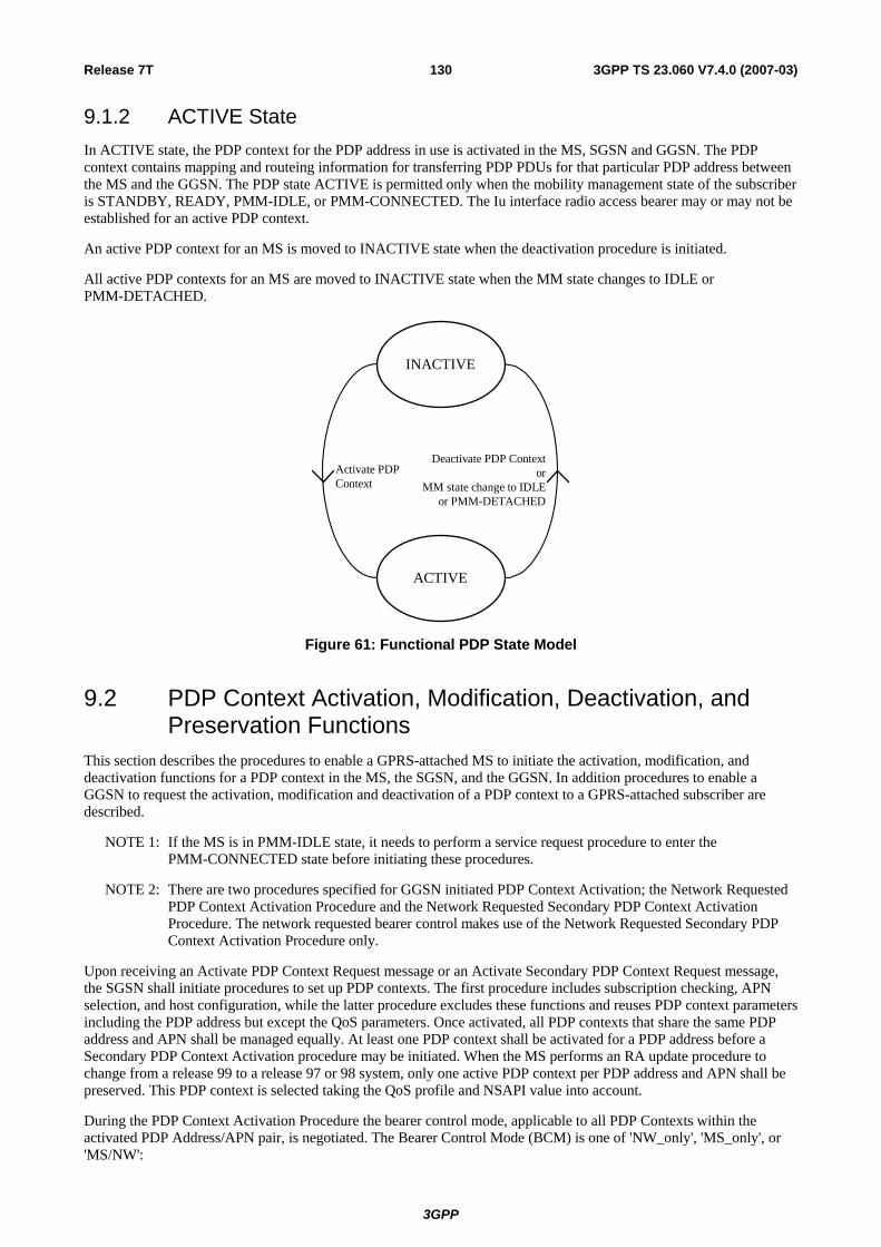
Release 7T 130 3GPP TS 23.060 V7.4.0 (2007-03)
9.1.2 ACTIVE State In ACTIVE state, the PDP context for the PDP address in use is activated in the MS, SGSN and GGSN. The PDP context contains mapping and routeing information for transferring PDP PDUs for that particular PDP address between the MS and the GGSN. The PDP state ACTIVE is permitted only when the mobility management state of the subscriber is STANDBY, READY, PMM-IDLE, or PMM-CONNECTED. The Iu interface radio access bearer may or may not be established for an active PDP context.
An active PDP context for an MS is moved to INACTIVE state when the deactivation procedure is initiated.
All active PDP contexts for an MS are moved to INACTIVE state when the MM state changes to IDLE or PMM-DETACHED.
Deactivate PDP Contextor
MM state change to IDLEor PMM-DETACHED
Activate PDPContext
INACTIVE
ACTIVE
Figure 61: Functional PDP State Model
9.2 PDP Context Activation, Modification, Deactivation, and Preservation Functions
This section describes the procedures to enable a GPRS-attached MS to initiate the activation, modification, and deactivation functions for a PDP context in the MS, the SGSN, and the GGSN. In addition procedures to enable a GGSN to request the activation, modification and deactivation of a PDP context to a GPRS-attached subscriber are described.
NOTE 1: If the MS is in PMM-IDLE state, it needs to perform a service request procedure to enter the PMM-CONNECTED state before initiating these procedures.
NOTE 2: There are two procedures specified for GGSN initiated PDP Context Activation; the Network Requested PDP Context Activation Procedure and the Network Requested Secondary PDP Context Activation Procedure. The network requested bearer control makes use of the Network Requested Secondary PDP Context Activation Procedure only.
Upon receiving an Activate PDP Context Request message or an Activate Secondary PDP Context Request message, the SGSN shall initiate procedures to set up PDP contexts. The first procedure includes subscription checking, APN selection, and host configuration, while the latter procedure excludes these functions and reuses PDP context parameters including the PDP address but except the QoS parameters. Once activated, all PDP contexts that share the same PDP address and APN shall be managed equally. At least one PDP context shall be activated for a PDP address before a Secondary PDP Context Activation procedure may be initiated. When the MS performs an RA update procedure to change from a release 99 to a release 97 or 98 system, only one active PDP context per PDP address and APN shall be preserved. This PDP context is selected taking the QoS profile and NSAPI value into account.
During the PDP Context Activation Procedure the bearer control mode, applicable to all PDP Contexts within the activated PDP Address/APN pair, is negotiated. The Bearer Control Mode (BCM) is one of 'NW_only', 'MS_only', or 'MS/NW':
3GPP

Release 7T 131 3GPP TS 23.060 V7.4.0 (2007-03)
- When 'NW_only' the GGSN shall request any additional PDP contexts for the PDP Address/APN pair through the Network Requested Secondary PDP Context Activation Procedure. Session Management procedures described in 9.2 apply with the following restrictions:
- The MS shall not initiate any Secondary PDP Context Activation;
NOTE 3: After a deactivation of the PDP context without TFT, the GGSN initiates the re-establishment of this PDP context using the Network Requested Secondary PDP Context Activation Procedure without sending a TFT to the MS.
- The MS shall not associate a TFT to a PDP context that was established without a TFT;
- The MS shall not modify or delete the TFT;
- The MS shall not upgrade the QoS of any PDP context.
- When 'MS_only' the MS shall request any additional PDP contexts for the PDP Address/APN pair through the Secondary PDP Context Activation Procedure. Session Management procedures described in 9.2 apply with the following restrictions:
- The GGSN shall not initiate any Network Requested Secondary PDP Context Activation;
- The GGSN shall not modify or delete the TFT.
- When 'MS/NW' both the MS and the GGSN may request additional PDP contexts for the PDP Address/APN pair. The MS shall use the Secondary PDP Context Activation Procedure. The GGSN shall use the Network Requested Secondary PDP Context Activation Procedure. Session Management procedures described in clause 9.2 apply with the following restrictions:
- The MS shall not upgrade the QoS of a PDP context until a TFT has been sent by the MS for this PDP context;
- The MS shall not initiate any Secondary PDP Context Activation without sending a TFT;
NOTE 4: After a deactivation of the PDP context without TFT, the GGSN initiates the re-establishment of this PDP context using the Network Requested Secondary PDP Context Activation Procedure without sending a TFT to the MS.
- The MS shall not add a TFT to a PDP context that was established without a TFT.
The MS indicates support of the network requested bearer control through the Network Request Support UE (NRSU) parameter. The SGSN indicates support of the network requested bearer control through the Network Request Support Network (NRSN) parameter.
If the NRSN is not included in the Update PDP Context Request message from the SGSN, or the SGSN does not indicate support of the network requested bearer control, the GGSN shall, following a SGSN-Initiated PDP Context Modification (triggered by SGSN change), perform a GGSN-Initiated PDP Context Modification to change the BCM to 'MS-Only' for all PDP-Address/APN-pairs for which the current BCM is 'NW_Only'.
Upon receiving a Deactivate PDP Context Request message, the SGSN shall initiate procedures to deactivate the PDP context. When the last PDP context associated with a PDP address is deactivated, N-PDU transfer for this PDP address is disabled.
An MS does not have to receive the (De-) Activate PDP Context Accept message before issuing another (De-)Activate PDP Context Request. However, only one request can be outstanding for every TI.
By sending a RAB Release Request or Iu Release Request message to the SGSN, the RAN initiates the release of one or more RABs. The preservation function allows the active PDP contexts associated with the released RABs to be preserved in the CN, and the RABs can then be re-established at a later stage.
3GPP

Release 7T 132 3GPP TS 23.060 V7.4.0 (2007-03)
9.2.1 Static and Dynamic PDP Addresses PDP addresses can be allocated to an MS in four different ways:
- the HPLMN operator assigns a PDP address permanently to the MS (static PDP address);
- the HPLMN operator assigns a PDP address to the MS when a PDP context is activated (dynamic HPLMN PDP address);
- the VPLMN operator assigns a PDP address to the MS when a PDP context is activated (dynamic VPLMN PDP address); or
- the PDN operator or administrator assigns a permanent or dynamic IP address to the MS (External PDN Address Allocation).
It is the HPLMN operator that defines in the subscription whether a dynamic HPLMN or VPLMN PDP address can be used.
For every IMSI, zero, one, or more dynamic PDP addresses per PDP type can be assigned. For every IMSI, zero, one, or more static PDP addresses per PDP type can be subscribed to.
When dynamic addressing from the HPLMN or the VPLMN is used, it is the responsibility of the GGSN to allocate and release the dynamic PDP address. When External PDN Address Allocation is used, the PLMN may obtain a PDP address from the PDN and provide it to the MS during PDP context activation, or the MS may directly negotiate a PDP address with the PDN after the PDP context activation procedure is executed. If the PLMN provides the address during PDP context activation in case of External PDN Address Allocation, then it is the responsibility of the GGSN and PDN to allocate and release the dynamic PDP address by means of protocols such as DHCP or RADIUS. If DHCP is used, the GGSN provides the function of a DHCP Client. If RADIUS is used, the GGSN provides the function of a RADIUS Client. If the MS negotiates a PDP address with the PDN after PDP context activation in case of External PDN Address Allocation, it is the responsibility of the MS and the PDN to allocate and release the PDP address by means of protocols such as DHCP or MIP. In case of DHCP, the GGSN provides the function of a DHCP Relay Agent as defined in RFC 2131 [47] and RFC 1542 [45]. In case of MIP, the GGSN provides the function of a Foreign Agent as defined in RFC 3344 [46].
Only static PDP addressing is applicable in the network-requested PDP context activation case.
9.2.1.1 Dynamic IPv6 Address Allocation
IPv6 address allocation is somewhat different from the IPv4 address allocation procedure. There are two possibilities to allocate the address for an IPv6 node – stateless and stateful autoconfiguration. The stateful address allocation mechanism needs a DHCP server to allocate the address for the IPv6 node. In the stateless autoconfiguration, the IPv6 node is more involved in the allocation of the address. In addition, the stateless autoconfiguration procedure does not need any external entity involved in the address autoconfiguration.
IPv6 stateful address autoconfiguration uses the standard External PDN Address Allocation procedure, as described in TS 29.061 [27]. The GGSN informs the MS that it shall perform stateful address autoconfiguration by means of the Router Advertisements, as defined in RFC 2461[71]. For this purpose, the GGSN shall automatically and periodically send Router Advertisement messages towards the MS after a PDP context of type IPv6 is activated. The use of stateless or stateful address autoconfiguration is configured per APN.
In order to support the standard IPv6 stateless address autoconfiguration mechanism, as defined by the IETF, within the particular context of UMTS (point-to-point connections, radio resource efficiency, etc), the GGSN shall assign a prefix that is unique within its scope to each PDP context applying IPv6 stateless address autoconfiguration. The size of the prefix is according to the maximum prefix length for a global IPv6 address. This avoids the necessity to perform duplicate address detection at the network level for every address built by the MS. The GGSN shall not use the prefix advertised to the MS to configure an address on any of its interfaces.
To ensure that the link-local address generated by the MS does not collide with the link-local address of the GGSN, the GGSN shall provide an interface identifier (see RFC 2462 [69]) to the MS and the MS shall use this interface identifier to configure its link-local address. This is applicable for both stateful and stateless IPv6 address autoconfiguration. In case of stateless address autoconfiguration however, the MS can choose any interface identifier to generate addresses other than link-local, without involving the network. In particular, the SGSN and the GGSN are not updated with the actual address used by the MS, as the prefix alone identifies the PDP context.
3GPP

Release 7T 133 3GPP TS 23.060 V7.4.0 (2007-03)
Figure 62 illustrates the IPv6 stateless autoconfiguration procedure The figure and its description show only the messages and actions specific to the IPv6 stateless address autoconfiguration procedure. For a complete description of the PDP Context Activation Procedure, refer to the corresponding clause.
GGSN
5. Router Advertisement
SGSN BSS/UTRANMS
4. Router Solicitation
3. Activate PDP Context Accept
1. Activate PDP Context Request 2. Create PDP Context Request
2. Create PDP Context Response
Figure 62: IPv6 Stateless Address Autoconfiguration Procedure
1) The MS sends an Activate PDP Context Request message to the SGSN as defined in clause "PDP Context Activation Procedure". The MS shall leave PDP Address empty and set PDP Type to IPv6.
2) Upon reception of the Create PDP Context Request, the GGSN creates an IPv6 address composed of the prefix allocated to the PDP context and an interface identifier generated by the GGSN. This address is then returned in the PDP Address information element in the Create PDP Context Response message. The processing of the Create PDP Context Request and Create PDP Context Response, in both the SGSN and the GGSN, is otherwise as specified in clause "PDP Context Activation Procedure".
NOTE: Since the MS is considered to be alone on its link towards the GGSN, the interface identifier does not need to be unique across all PDP contexts on any APN.
3) The MS receives the IPv6 address produced by the GGSN in the Activate PDP Context Accept. The MS extracts the interface identifier from the address received and stores it. The MS shall use this interface identifier to build its link-local address and may also use it for building its full IPv6 address, as describe in step 5. The MS shall ignore the prefix contained in the address received in the Activate PDP Context Accept. The processing of the Activate PDP Context Accept is otherwise as specified in clause "PDP Context Activation Procedure".
4) The MS may send a Router Solicitation message to the GGSN to activate the sending of the Router Advertisement message.
5) The GGSN sends a Router Advertisement message. The Router Advertisement messages shall contain the same prefix as the one provided in step 2. A given prefix shall not be advertised on more than one PDP context on a given APN, or set of APNs, within the same addressing scope. The GGSN shall be configured to advertise only one prefix per PDP context.
After the MS has received the Router Advertisement message, it constructs its full IPv6 address by concatenating the interface identifier received in step 3, or a locally generated interface identifier, and the prefix received in the Router Advertisement. If the Router Advertisement contains more than one prefix option, the MS shall only consider the first one and silently discard the others.
NOTE: The MS can at any time change the interface identifier used to generate full IPv6 addresses, without involving the network, i.e. without updating the PDP context in the SGSN and the GGSN.
Because any prefix that the GGSN advertises in a PDP context is unique within the scope of the prefix (i.e. site-local or global), there is no need for the MS to perform Duplicate Address Detection for this IPv6 address. Therefore, the GGSN shall silently discard Neighbor Solicitation messages that the MS may send to perform Duplicate Address Detection. It is possible for the MS to perform Neighbor Unreachability Detection towards the GGSN, as defined in RFC 2461 [71]; therefore if the GGSN receives a Neighbor Solicitation as part of this procedure, the GGSN shall provide a Neighbor Advertisement as described in RFC 2461[71].
3GPP

Release 7T 134 3GPP TS 23.060 V7.4.0 (2007-03)
9.2.2 Activation Procedures
9.2.2.1 PDP Context Activation Procedure
The PDP Context Activation procedure is illustrated in Figure 63 and Figure 64.
GGSN
9. Activate PDP Context Accept
4. Create PDP Context Response
4. Create PDP Context Request
1. Activate PDP Context Request
SGSN BSS
2. Security Functions
MS
7. BSS Packet Flow Context Procedures
C1
C2
3. Invoke Trace
8. Update PDP Context Request
8. Update PDP Context Response
Figure 63: PDP Context Activation Procedure for A/Gb mode
GGSN
9. Activate PDP Context Accept
4. Create PDP Context Response
4. Create PDP Context Request
1. Activate PDP Context Request
SGSNRANMS
5. Radio Access Bearer Setup
C1
C2
6. Invoke Trace
8. Update PDP Context Response
8. Update PDP Context Request
Figure 64: PDP Context Activation Procedure for Iu mode
1) The MS sends an Activate PDP Context Request (NSAPI, TI, PDP Type, PDP Address, Access Point Name, QoS Requested, Protocol Configuration Options) message to the SGSN. The MS shall use PDP Address to indicate whether it requires the use of a static PDP address or whether it requires the use of a dynamic PDP address. The MS shall leave PDP Address empty to request a dynamic PDP address. The MS may use Access Point Name to select a reference point to a certain packet data network and/or to select a service. Access Point
3GPP

Release 7T 135 3GPP TS 23.060 V7.4.0 (2007-03)
Name is a logical name referring to the packet data network and/or to a service that the subscriber wishes to connect to. QoS Requested indicates the desired QoS profile. Protocol Configuration Options is used to transfer the NRSU to the GGSN and may be used to transfer the BCM as well as optional PDP parameters and/or request to the GGSN (see GSM 29.060 [26] and 24.229 [75]). Protocol Configuration Options is sent transparently through the SGSN. NRSU indicates MS support of the network requested bearer control. The BCM parameter may be included by the MS to indicate the preferred Bearer Control Mode applicable to all PDP Contexts within the activated PDP Address/APN pair.
If the SGSN has stored a value for the Maximum APN restriction and the value indicates the most restrictive type, then the SGSN shall reject any Activate PDP Context requests to a different APN, using the PDP Context Activation Reject message including an appropriate error cause.
If the SGSN decides to establish Direct Tunnel between RNC and GGSN, the SGSN provides to the RNC the Direct Tunnel specific parameters in step 5 "RAB Assignment Procedure" and shall initiate PDP Context Update procedure in step 8 to update IP Address and TEID for Downlink data.
If the Activate PDP Context Request is for an IMS Emergency Registration as specified in TS 23.167 [89], the MS shall leave the PDP Address empty to request a dynamic PDP address and use the Emergency Access Point Name, Em-APN, as defined in TS 23.003 [4].
2) In A/Gb mode, security functions may be executed. These procedures are defined in clause "Security Function".
3) In A/Gb mode and if BSS trace is activated, the SGSN shall send an Invoke Trace (Trace Reference, Trace Type, Trigger Id, OMC Identity) message to the BSS. Trace Reference, and Trace Type are copied from the trace information received from the HLR or OMC.
4) The SGSN validates the Activate PDP Context Request using PDP Type (optional), PDP Address (optional), and Access Point Name (optional) provided by the MS and the PDP context subscription records. The validation criteria, the APN selection criteria, and the mapping from APN to a GGSN are described in annex A.
If no GGSN address can be derived or if the SGSN has determined that the Activate PDP Context Request is not valid according to the rules described in annex A, the SGSN rejects the PDP context activation request.
If a GGSN address can be derived, the SGSN creates a TEID for the requested PDP context. If the MS requests a dynamic address, the SGSN lets a GGSN allocate the dynamic address. The SGSN may restrict the requested QoS attributes given its capabilities and the current load, and it shall restrict the requested QoS attributes according to the subscribed QoS profile.
The SGSN sends a Create PDP Context Request (PDP Type, PDP Address, Access Point Name, QoS Negotiated, TEID, NSAPI, MSISDN, Selection Mode, Charging Characteristics, Trace Reference, Trace Type, Trigger Id, OMC Identity, Protocol Configuration Options, serving network identity, Maximum APN Restriction IMEISV, CGI/SAI, RAT type, S-CDR CAMEL information, CGI/SAI/RAI change support indication, NRSN) message to the affected GGSN. The SGSN shall send the serving network identity to the GGSN. Access Point Name shall be the APN Network Identifier of the APN selected according to the procedure described in Annex A. PDP Address shall be empty if a dynamic address is requested. The GGSN may use Access Point Name to find a packet data network and optionally to activate a service for this APN. If the APN-NI is the globally defined Em-APN then the GGSN shall ensure that only certain IP addresses can be reached. Selection Mode indicates whether a subscribed APN was selected, or whether a non-subscribed APN sent by an MS or a non-subscribed APN chosen by the SGSN was selected. Selection Mode is set according to Annex A. The GGSN may use Selection Mode when deciding whether to accept or reject the PDP context activation. For example, if an APN requires subscription, the GGSN is configured to accept only the PDP context activation that requests a subscribed APN as indicated by the SGSN with Selection Mode. The Em-APN does not require any subscription. Charging Characteristics indicates which kind of charging the PDP context is liable for. The charging characteristics on the GPRS subscription and individually subscribed APNs as well as the way the SGSN handles Charging Characteristics and chooses to send them or not to the GGSN is defined in TS 32.215 [70]. The SGSN shall include Trace Reference, Trace Type, Trigger Id, and OMC Identity if GGSN trace is activated. The SGSN shall copy Trace Reference, Trace Type, and OMC Identity from the trace information received from the HLR or OMC. The Maximum APN Restriction denotes the most stringent restriction as required by any already active PDP contexts. If there are no already active PDP contexts, this value is set to the least restrictive type (see clause 15.4). If the GGSN receives the Maximum APN Restriction, then the GGSN shall check if the Maximum APN Restriction value does not conflict with the APN Restriction value associated with this PDP context request. If there is no conflict the request shall be allowed, otherwise the request shall be rejected with the SGSN sending a PDP Context Activation Reject Message to the MS including an appropriate error cause. NRS indicates SGSN support of the network requested bearer control.
3GPP

Release 7T 136 3GPP TS 23.060 V7.4.0 (2007-03)
The GGSN creates a new entry in its PDP context table and generates a Charging Id. The new entry allows the GGSN to route PDP PDUs between the SGSN and the packet data network, and to start charging. The way the GGSN handles Charging Characteristics that it may have received from the SGSN is defined in TS 32.215 [70]. The GGSN may restrict QoS Negotiated given its capabilities and the current load or increase the QoS Negotiated based on any external input (e.g. policy control). The GGSN then returns a Create PDP Context Response (TEID, PDP Address, Protocol Configuration Options, QoS Negotiated, Charging Id, Prohibit Payload Compression, APN Restriction, Cause, CGI/SAI/RAI change report required, BCM) message to the SGSN. The Prohibit Payload Compression indicates that the SGSN should negotiate no data compression for this PDP context. PDP Address is included if the GGSN allocated a PDP address. If the GGSN has been configured by the operator to use External PDN Address Allocation for the requested APN, PDP Address shall be set to 0.0.0.0, indicating that the PDP address shall be negotiated by the MS with the external PDN after completion of the PDP Context Activation procedure. The GGSN shall relay, modify and monitor these negotiations as long as the PDP context is in ACTIVE state, and use the GGSN-Initiated PDP Context Modification procedure to transfer the currently used PDP address to the SGSN and the MS. Protocol Configuration Options contains the BCM as well as optional PDP parameters that the GGSN may transfer to the MS. BCM shall also be sent as a separate IE to the SGSN. These optional PDP parameters may be requested by the MS in the Activate PDP Context Request message, or may be sent unsolicited by the GGSN. Protocol Configuration Options is sent transparently through the SGSN. The Create PDP Context messages are sent over the backbone network. The BCM is used by the SGSN to handle unexpected session management signalling.
If QoS Negotiated received from the SGSN is incompatible with the PDP context being activated, the GGSN rejects the Create PDP Context Request message. The GGSN operator configures the compatible QoS profiles.
If an APN Restriction is received from the GGSN for this PDP Context, then the SGSN shall store this value for the PDP Context and the SGSN shall check this received value with the stored value for the Maximum APN Restriction to ensure there are no conflicts between values. If the consequence of this check results in the PDP context being rejected, the SGSN shall initiate a PDP Context Deactivation and return an appropriate error cause. If the PDP Context is accepted, it shall determine a (new) value for the Maximum APN Restriction. If there is no previously stored value for Maximum APN Restriction, then the Maximum APN Restriction shall be set to the value of the received APN Restriction.
If the CGI/SAI/RAI change report required is received from the GGSN for this PDP context, then the SGSN shall store this for the PDP context and the SGSN shall report to that GGSN whenever a CGI/SAI/RAI change occurs that meets the GGSN request, as described in clause 15.1.1a.
The GGSN derives the BCM based on NRSU, NRSN and operator policy, and MS-preferred Bearer Control Mode if previously received in the Create PDP Context Request message. The derived BCM is sent to the MS indicating the Bearer Control Mode applicable to all PDP Contexts within the activated PDP Address/APN pair.
The SGSN shall re-verify and may restrict the QoS Negotiated received in the response from the GGSN against the subscribed QoS profile and additionally restrict the QoS negotiated based on its capabilities and current load. The SGSN shall use this updated QoS Negotiated for the subsequent steps.
5) In Iu mode, RAB setup is done by the RAB Assignment procedure, see subclause "RAB Assignment Procedure".
6) In Iu mode and if BSS trace is activated, the SGSN shall send an Invoke Trace (Trace Reference, Trace Type, Trigger Id, OMC Identity) message to the RAN. Trace Reference, and Trace Type are copied from the trace information received from the HLR or OMC.
NOTE: Step 6 is applied when the trace activation is triggered by means of signalling. Another alternative is the triggering of trace activation by the OMC. The details of both Trace Activation procedures are described in TS 32.422 [84].
7) In A/Gb mode, BSS packet flow context procedures may be executed. These procedures are defined in clause "BSS Context".
8) In case the QoS attributes, used as input to step 5 for Iu mode or step 7 for A/Gb mode, have been downgraded during those steps, the SGSN may inform the GGSN about the downgraded QoS attributes by sending an Update PDP Context Request to the affected GGSN. The GGSN shall not attempt to renegotiate the QoS attributes. The No QoS negotiation indication is set in Update PDP Context Request to indicate to the GGSN that the SGSN does not upgrade the previously negotiated QoS attributes and that the GGSN shall accept the provided QoS attributes without negotiation. The GGSN confirms the new QoS attributes by sending an Update PDP Context Response to the SGSN. If the SGSN established Direct Tunnel in step 5 it shall send Update PDP Context Request and include the RNC's Address for User Plane, TEID for downlink data, No QoS negotiation indication
3GPP

Release 7T 137 3GPP TS 23.060 V7.4.0 (2007-03)
and the DTI. DTI is used to instruct the GGSN to apply Direct Tunnel specific error handling as described in clause 13.8.
9) The SGSN inserts the NSAPI along with the GGSN address in its PDP context. If the MS has requested a dynamic address, the PDP address received from the GGSN is inserted in the PDP context. The SGSN selects Radio Priority and Packet Flow Id based on QoS Negotiated, and returns an Activate PDP Context Accept (PDP Type, PDP Address, TI, QoS Negotiated, Radio Priority, Packet Flow Id, Protocol Configuration Options) message to the MS. If the MS indicated in the MS Network Capability it does not support BSS packet flow procedures, then the SGSN shall not include the Packet Flow Id. In A/Gb mode, the QoS Negotiated shall take into account the Aggregate BSS QoS Profile, if any, returned from the BSS. Protocol Configuration Options are used to transfer the BCM to the UE and may be used to transfer optional PDP parameters to the UE (see GSM 29.060 [26] and 24.229 [75]). Protocol Configuration Options is sent transparently through the SGSN. The BCM indicates the Bearer Control Mode applicable to all PDP Contexts within the activated PDP Address/APN pair. If the BCM parameter is not included in the message then the MS shall set the Bearer Control Mode to 'MS_Only' for the PDP Address/APN pair (see clause 9.2). The SGSN is now able to route PDP PDUs between the GGSN and the MS, and to start charging.
If the MS is incapable of accepting the new QoS Negotiated, the MS should initiate application level signalling to lower the QoS requirements for the concerned application(s). If this is not possible then the MS shall instead de-activate the PDP context with the PDP Context Deactivation Initiated by the MS procedure.
For each PDP Address a different quality of service (QoS) profile may be requested. For example, some PDP addresses may be associated with E-mail that can tolerate lengthy response times. Other applications cannot tolerate delay and demand a very high level of throughput, interactive applications being one example. These different requirements are reflected in the QoS profile. The QoS profile is defined in clause "Quality of Service Profile". If a QoS requirement is beyond the capabilities of a PLMN, the PLMN negotiates the QoS profile as close as possible to the requested QoS profile. The MS either accepts the negotiated QoS profile, or deactivates the PDP context.
After an SGSN has successfully updated the GGSN, the PDP contexts associated with an MS is distributed as shown in clause "Information Storage".
If the PDP Context Activation Procedure fails or if the SGSN returns an Activate PDP Context Reject (Cause, Protocol Configuration Options) message, the MS may attempt another activation to the same APN up to a maximum number of attempts.
The CAMEL procedure calls shall be performed, see referenced procedures in TS 23.078 [8b]:
C1) CAMEL_GPRS_PDP_Context_Establishment.
In Figure 63 and Figure 64, procedures return as result "Continue".
C2) CAMEL_GPRS_PDP_Context_Establishment_Acknowledgement.
In Figure 63 and Figure 64, procedures return as result "Continue".
9.2.2.1.1 Secondary PDP Context Activation Procedure
The Secondary PDP Context Activation procedure may be used to activate a PDP context while reusing the PDP address and other PDP context information from an already active PDP context, but with a different QoS profile. Procedures for APN selection and PDP address negotiation are not executed. A unique TI and a unique NSAPI shall identify each PDP context sharing the same PDP address and APN.
The Secondary PDP Context Activation procedure may be executed without providing a Traffic Flow Template (TFT) to the newly activated PDP context if all other active PDP contexts for this PDP address and APN already have an associated TFT. Otherwise a TFT shall be provided. The TFT contains attributes that specify an IP header filter that is used to direct data packets received from the interconnected packet data network to the newly activated PDP context.
3GPP
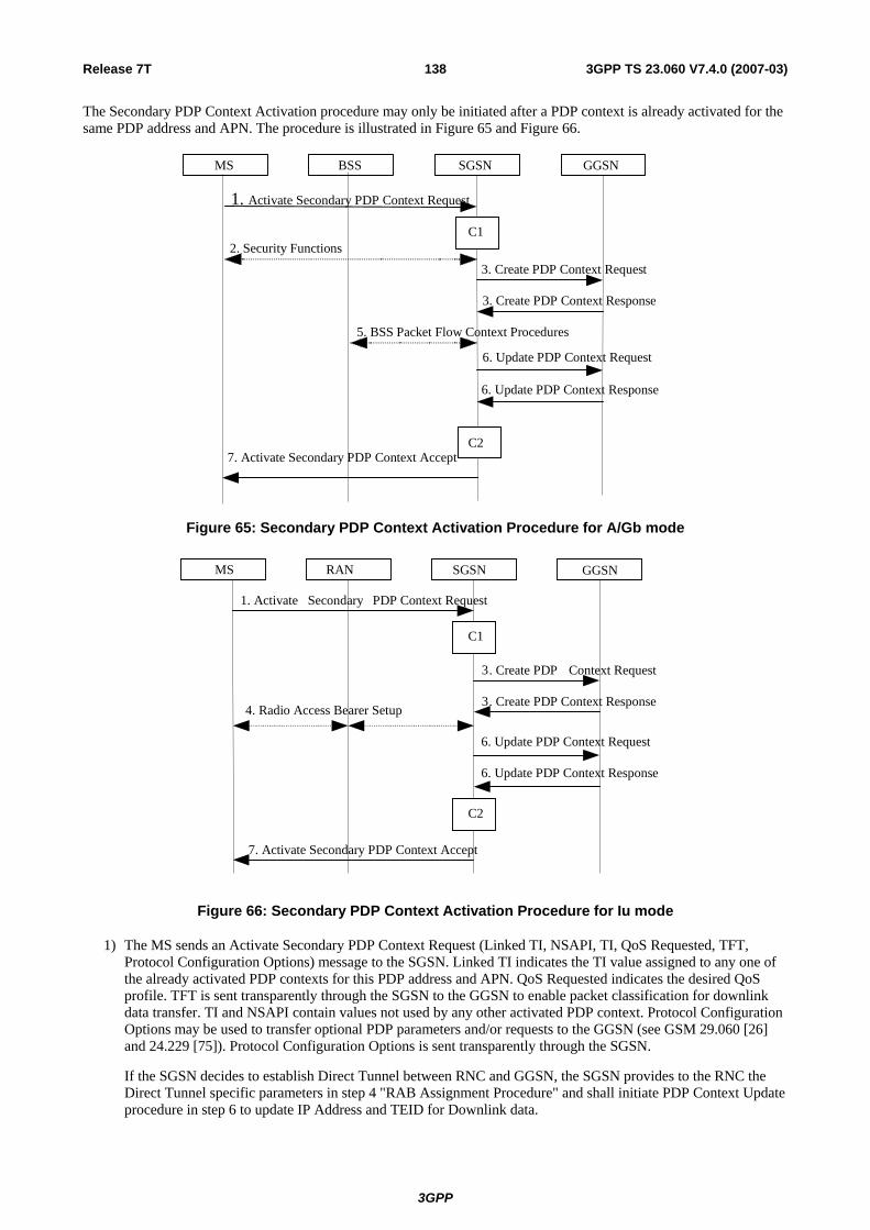
Release 7T 138 3GPP TS 23.060 V7.4.0 (2007-03)
The Secondary PDP Context Activation procedure may only be initiated after a PDP context is already activated for the same PDP address and APN. The procedure is illustrated in Figure 65 and Figure 66.
GGSN
7. Activate Secondary PDP Context Accept
3. Create PDP Context Response
3. Create PDP Context Reques t
1. Activate Secondary PDP Context Request
SGSN BSS
2. Security Functions
MS
5. BSS Packet Flow Context Procedures
C1
C2
6. Update PDP Context Request
6. Update PDP Context Response
Figure 65: Secondary PDP Context Activation Procedure for A/Gb mode
GGSN
7. Activate Secondary PDP Context Accept
3 . Create PDP Context Response
3 . Create PDP Context Request
1. Activate Secondary PDP Context Request
SGSNRAN MS
4. Radio Access Bearer Setup
C1
C2
6. Update PDP Context Response
6. Update PDP Context Request
Figure 66: Secondary PDP Context Activation Procedure for Iu mode
1) The MS sends an Activate Secondary PDP Context Request (Linked TI, NSAPI, TI, QoS Requested, TFT, Protocol Configuration Options) message to the SGSN. Linked TI indicates the TI value assigned to any one of the already activated PDP contexts for this PDP address and APN. QoS Requested indicates the desired QoS profile. TFT is sent transparently through the SGSN to the GGSN to enable packet classification for downlink data transfer. TI and NSAPI contain values not used by any other activated PDP context. Protocol Configuration Options may be used to transfer optional PDP parameters and/or requests to the GGSN (see GSM 29.060 [26] and 24.229 [75]). Protocol Configuration Options is sent transparently through the SGSN.
If the SGSN decides to establish Direct Tunnel between RNC and GGSN, the SGSN provides to the RNC the Direct Tunnel specific parameters in step 4 "RAB Assignment Procedure" and shall initiate PDP Context Update procedure in step 6 to update IP Address and TEID for Downlink data.
3GPP

Release 7T 139 3GPP TS 23.060 V7.4.0 (2007-03)
2) In A/Gb mode, security functions may be executed. These procedures are defined in clause "Security Function".
3) The SGSN validates the Activate Secondary PDP Context Request using the TI indicated by Linked TI. The same GGSN address is used by the SGSN as for the already-activated PDP context(s) for that TI and PDP address.
The SGSN may restrict the requested QoS attributes given its capabilities and the current load, and it shall restrict the requested QoS attributes according to the subscribed QoS profile, which represents the maximum QoS per PDP context to the associated APN. The GGSN may restrict or increase, and negotiate the requested QoS as specified in clause "PDP Context Activation Procedure". The SGSN sends a Create PDP Context Request (QoS Negotiated, TEID, NSAPI, Primary NSAPI, TFT, Protocol Configuration Options, serving network identity, IMEISV, CGI/SAI, RAT type, S-CDR CAMEL information, CGI/SAI/RAI change support indication, Correlation-ID) message to the affected GGSN. The SGSN shall send the serving network identity to the GGSN. Primary NSAPI indicates the NSAPI value assigned to any one of the already activated PDP contexts for this PDP address and APN. TFT is included only if received in the Activate Secondary PDP Context Request message. Protocol Configuration Options is sent transparently through the SGSN if received in the Activate secondary PDP Context Request message. The Correlation-ID shall only be included if the Secondary PDP Context Activation is performed as part of the Network Requested Secondary PDP Context Activation Procedure (clause 9.2.2.3), and shall be linked to the TI as described in clause 9.2.2.3.
The GGSN uses the same packet data network as used by the already-activated PDP context(s) for that PDP address, generates a new entry in its PDP context table, and stores the TFT. The new entry will allow the GGSN to route PDP PDUs via different GTP tunnels between the SGSN and the packet data network. The GGSN returns a Create PDP Context Response (TEID, QoS Negotiated, Cause, Protocol Configuration Options, Prohibit Payload Compression, APN Restriction, CGI/SAI/RAI change report required) message to the SGSN. Protocol Configuration Options may be used to transfer optional PDP parameters to the UE (see GSM 29.060 [26] and 24.229 [75]). The Prohibit Payload Compression indicates that the SGSN should negotiate no data compression for this PDP context. If an APN Restriction is received from the GGSN for this PDP Context, then the SGSN shall store this value for the PDP Context.
If the CGI/SAI/RAI report required is received from the GGSN for this PDP context, then the SGSN shall store this for the PDP context and the SGSN shall report to that GGSN whenever a CGI/SAI/RAI change occurs that meets the GGSN request.
The SGSN shall re-verify and may restrict the QoS Negotiated received from the GGSN against the subscribed QoS profile and additionally restrict the QoS negotiated based on its capabilities and current load. The SGSN shall use this updated QoS Negotiated for the subsequent steps.
4) In Iu mode, RAB setup is done by the RAB Assignment procedure.
5) In A/Gb mode, BSS packet flow context procedures may be executed. These procedures are defined in clause "BSS Context".
6) The SGSN sends an Update PDP Context Request message to the GGSN, including the QoS attributes that have been accepted by the RAN. In case the QoS attributes have been downgraded in step 5 for A/Gb mode or in step 4 for Iu mode, the SGSN may inform the GGSN about the downgraded QoS. The GGSN shall not attempt to renegotiate the QoS attributes. A RAN Procedures Ready flag is included in the Update PDP Context Request. A GGSN that receives an Update PDP Context Request with a RAN Procedures Ready flag set, should start to route downlink PDP PDUs immediately. The No QoS negotiation indication is set in Update PDP Context Request to indicate to the GGSN that the SGSN does not upgrade the previously negotiated QoS attributes and that the GGSN shall accept the provided QoS attributes without negotiation. The GGSN confirms the reception of the message and the potentially downgraded QoS attributes by sending an Update PDP Context Response to the SGSN. If the SGSN established Direct Tunnel in step 4 it shall send Update PDP Context Request and include the RNC's Address for User Plane and downlink TEID for data, the No QoS negotiation indication and DTI. DTI is used to instruct the GGSN to apply Direct Tunnel specific error handling as described in clause 13.8.
7) The SGSN selects Radio Priority and Packet Flow Id based on QoS Negotiated, and returns an Activate Secondary PDP Context Accept (TI, QoS Negotiated, Radio Priority, Packet Flow Id, Protocol Configuration Options) message to the MS. If the MS indicated in the MS Network Capability it does not support BSS packet flow procedures, then the SGSN shall not include the Packet Flow Id. In A/Gb mode, the QoS Negotiated shall take into account the Aggregate BSS QoS Profile, if any, returned from the BSS. Protocol Configuration Options is sent transparently through the SGSN if received in the Create PDP Context Response message. The SGSN is
3GPP

Release 7T 140 3GPP TS 23.060 V7.4.0 (2007-03)
now able to route PDP PDUs between the GGSN and the MS via different GTP tunnels and possibly different LLC links.
If the MS is incapable of accepting the new QoS Negotiated, the MS should initiate application level signalling to lower the QoS requirements for the concerned application(s). If this is not possible then the MS shall instead de-activate the PDP context with the PDP Context Deactivation Initiated by the MS procedure.
For each additionally activated PDP context a QoS profile and TFT may be requested.
If the secondary PDP context activation procedure fails or if the SGSN returns an Activate Secondary PDP Context Reject (Cause, Protocol Configuration Options) message, the MS may attempt another activation with a different TFT, depending on the cause.
The CAMEL procedure calls shall be performed, see referenced procedures in TS 23.078 [8b]:
C1) CAMEL_GPRS_PDP_Context_Establishment.
In Figure 65 and in Figure 66, procedures return as result "Continue".
C2) CAMEL_GPRS_PDP_Context_Establishment_Acknowledgement.
In Figure 65 and in Figure 66, procedures return as result "Continue".
9.2.2.2 Network-Requested PDP Context Activation Procedure
The Network-Requested PDP Context Activation procedure allows the GGSN to initiate the activation of a PDP context. When receiving a PDP PDU the GGSN checks if a PDP context is established for that PDP address. If no PDP context has been previously established, the GGSN may try to deliver the PDP PDU by initiating the Network-Requested PDP Context Activation procedure. The criteria used by the GGSN to determine whether trying to deliver the PDP PDU to the MS may be based on subscription information are outside the scope of GPRS standardisation.
To support Network-Requested PDP Context Activation, the GGSN has to have static PDP information about the PDP address. To determine whether Network-Requested PDP Context Activation is supported for a PDP address, the GGSN checks if there is static PDP information for that PDP address.
Once these checks have been performed the GGSN may initiate the Network-Requested PDP Context Activation procedure.
The network operator may implement the following techniques to prevent unnecessary enquires to the HLR:
- Implementation of the Mobile station Not Reachable for GPRS flag (MNRG) technique in GGSN, SGSN, and HLR (see clause "Unsuccessful Network-Requested PDP Context Activation Procedure").
- The GGSN may reject or discard PDP PDUs after a previous unsuccessful delivery attempt. This systematic rejection of PDP PDUs would be performed during a certain time after the unsuccessful delivery.
- The GGSN may store the address of the SGSN with which the GGSN established the last PDP context. This would prevent an enquiry to the HLR. This SGSN address would be considered as valid during a certain time.
3GPP

Release 7T 141 3GPP TS 23.060 V7.4.0 (2007-03)
9.2.2.2.1 Successful Network-Requested PDP Context Activation Procedure
The Successful Network-Requested PDP Context Activation procedure is illustrated in Figure 67.
MS SGSN GGSN
3. PDU Notification Request
HLR
1. PDP PDU
2. Send Routeing Info for GPRS
2. Send Routeing Info for GPRS Ack
4. Request PDP Context Activation
5. PDP Context Activation procedure
3. PDU Notification Response
Figure 67: Successful Network-Requested PDP Context Activation Procedure
1) When receiving a PDP PDU the GGSN determines if the Network-Requested PDP Context Activation procedure has to be initiated. The GGSN may store subsequent PDP PDUs received for the same PDP address.
2) The GGSN may send Send Routeing Information for GPRS (IMSI) message to the HLR. If the HLR determines that the request can be served, it returns Send Routeing Information for GPRS Ack (IMSI, SGSN Address, Mobile Station Not Reachable Reason) message to the GGSN. The Mobile Station Not Reachable Reason parameter is included if the MNRG flag is set in the HLR. The Mobile Station Not Reachable Reason parameter indicates the reason for the setting of the MNRG flag as stored in the MNRR record (see GSM 03.40). If the MNRR record indicates a reason other than "No Paging Response", the HLR shall include the GGSN number in the GGSN-list of the subscriber.
If the HLR determines that the request cannot be served (e.g. IMSI unknown in HLR), the HLR shall send a Send Routeing Information for GPRS Ack (IMSI, MAP Error Cause) message. Map Error Cause indicates the reason for the negative response.
3) If the SGSN address is present and either Mobile Station Not Reachable Reason is not present or Mobile Station Not Reachable Reason indicates "No Paging Response", the GGSN shall send a PDU Notification Request (IMSI, PDP Type, PDP Address, APN) message to the SGSN indicated by the HLR. Otherwise, the GGSN shall set the MNRG flag for that MS. The SGSN returns a PDU Notification Response (Cause) message to the GGSN in order to acknowledge that it shall request the MS to activate the PDP context indicated with PDP Address.
4) The SGSN sends a Request PDP Context Activation (TI, PDP Type, PDP Address, APN) message to request the MS to activate the indicated PDP context.
5) The PDP context is activated with the PDP Context Activation procedure (see clause "PDP Context Activation Procedure").
9.2.2.2.2 Unsuccessful Network-Requested PDP Context Activation Procedure
If the PDP context requested by the GGSN cannot be established, the SGSN sends a PDU Notification Response (Cause) or a PDU Notification Reject Request (IMSI, PDP Type, PDP Address, Cause) message to the GGSN depending on if the context activation fails before or after the SGSN has sent a Request PDP Context Activation message to the MS. Cause indicates the reason why the PDP context could not be established:
- "IMSI Not Known". The SGSN has no MM context for that IMSI (Cause in PDU Notification Response).
- "MS GPRS Detached". The MM state of the MS is IDLE (Cause in PDU Notification Response).
3GPP

Release 7T 142 3GPP TS 23.060 V7.4.0 (2007-03)
- "MS Not GPRS Responding". The MS is GPRS-attached to the SGSN but the MS does not respond. This may be due to the lack of a response to a GPRS Paging Request, due to an Abnormal RLC condition, or due to no Activate PDP Context Request message received within a certain time after the Request PDP Context Activation message was delivered to the MS (Cause in PDU Notification Reject Request).
- "MS Refuses". The MS refuses explicitly the network-requested PDP context (Cause in PDU Notification Reject Request).
When receiving the PDU Notification Response or the PDU Notification Reject Request message, the GGSN may reject or discard the PDP PDU depending on the PDP type.
After an unsuccessful Network-Requested PDP Context Activation procedure the network may perform some actions to prevent unnecessary enquires to the HLR. The actions taken depend on the cause of the delivery failure.
- If the MS is not reachable or if the MS refuses the PDP PDU (Cause value "MS Not GPRS Responding" or "MS Refuses"), the SGSN shall not change the setting of MNRG for this MS. The GGSN may refuse any PDP PDU for that PDP address during a certain period. The GGSN may store the SGSN address during a certain period and send subsequent PDU Notification Request messages to that SGSN.
- If the MS is GPRS-detached or if the IMSI is not known in the SGSN (Cause value "MS GPRS Detached" or "IMSI Not Known"), the SGSN, the GGSN, and the HLR may perform the Protection and Mobile User Activity procedures.
The Protection procedure is illustrated in Figure 68.
SGSN HLR GGSN
1. PDU Notification Response
3. Send Routeing Info for GPRS
3. Send Routeing Info for GPRS Ack
4. Failure Report
4. Failure Report Ack
2. PDU Notification Reject Response
2. PDU Notification Reject Request
Figure 68: Protection Procedure
1) If the MM context of the mobile is IDLE or if the SGSN has no information about that user, the SGSN returns a PDU Notification Response (Cause) message to the GGSN with Cause equal to "MS GPRS Detached" or "IMSI Not Known". Otherwise, the Cause shall be "Activation Proceeds". If the Cause is "MS GPRS Detached" or "IMSI Not Known" and if the SGSN has an MM context for that user, the SGSN sets MNRG to indicate the need to report to the HLR when the next contact with that MS is performed.
2) If the MS does not respond or refuses the activation request, the SGSN sends a PDU Notification Reject Request (IMSI, PDP Type, PDP Address, Cause) message to the GGSN with Cause equal to "MS Not GPRS Responding" or "MS Refuses". The GGSN returns a PDU Notification Reject Response message to the SGSN.
3) If Cause equals "IMSI Not Known", the GGSN may send Send Routeing Information for GPRS (IMSI) message to the HLR. The HLR returns Send Routeing Information for GPRS Ack (IMSI, SGSN Address, Cause) message to the GGSN indicating the address of the SGSN that currently serves the MS. If SGSN Address is different from the one previously stored by the GGSN, then steps 3, 4, and 5 in Figure 67 are followed.
3GPP

Release 7T 143 3GPP TS 23.060 V7.4.0 (2007-03)
4) If SGSN Address is the same as the one previously stored in the GGSN, or if the Cause value returned in step 1 equals "MS GPRS Detached", then the GGSN sets MNRG for all PDP address(es) for that MS and sends a Failure Report (IMSI, GGSN Number, GGSN Address) message to the HLR to request MNRG to be set in the HLR. The HLR sets (if not already set) MNRG for the IMSI and adds GGSN Number and GGSN Address to the list of GGSNs to report to when activity from that IMSI is detected. GGSN Number is either the number of the GGSN, or, if a protocol-converting GSN is used as an intermediate node, the number of the protocol-converting GSN. GGSN Address is an optional parameter that shall be included if a protocol-converting GSN is used.
The Mobile User Activity procedure is illustrated in Figure 69.
3. Note MS GPRS Present
SGSN HLR GGSN
1. Attach Request 2a. Ready for SM
2b. Update Location
MS
Figure 69: Mobile User Activity Procedure
1) The SGSN receives an indication that an MS is reachable, e.g., an Attach Request message from the MS.
2a) If the SGSN contains an MM context of the MS and MNRG for that MS is set, the SGSN shall send a Ready for SM (IMSI, MS Reachable) message to the HLR and clears MNRG for that MS.
2b) If the SGSN does not keep the MM context of the MS, the SGSN shall send an Update Location message (see subclause "GPRS Attach Function") to the HLR.
3) When the HLR receives the Ready for SM message or the Update Location message for an MS that has MNRG set, it clears MNRG for that MS and sends a Note MS GPRS Present (IMSI, SGSN Address) message to all the GGSNs in the list of the subscriber. (The Ready for SM message also triggers the SMS alert procedure as described in subclause "Unsuccessful Mobile-terminated SMS Transfer".) SGSN Address field is the address of the SGSN that currently serves the MS. Upon reception of Note MS Present each GGSN shall clear MNRG.
9.2.2.3 Network Requested Secondary PDP Context Activation Procedure
The Network Requested Secondary PDP Context Activation Procedure allows the GGSN to initiate the Secondary PDP Context Activation Procedure (see clause 9.2.2.1.1). The Network Requested Secondary PDP Context Activation Procedure is illustrated in figure 69b.
2. Request Secondary PDP Context Activation
GGSN
1. Initiate PDP Context Activation
SGSN RAN MS
3. Secondary PDP Context Activation Procedure
Figure 69b: Network Requested Secondary PDP Context Activation Procedure
1) The GGSN sends an Initiate PDP Context Activation (Linked NSAPI, QoS Requested, TFT, Protocol Configuration Options, Correlation-ID) message to the SGSN. The QoS Requested, TFT, and Protocol Configuration Options are sent transparently through the SGSN. The TFT shall contain downlink- and uplink packet filters. The Correlation-ID is used by the GGSN to correlate the subsequent Secondary PDP Context Activation Procedure (as described below) with this message. To re-establish the PDP context without TFT the GGSN shall send the Initiate PDP Context Activation message without a TFT.
3GPP

Release 7T 144 3GPP TS 23.060 V7.4.0 (2007-03)
2) The SGSN sends a Request Secondary PDP Context Activation (Linked TI, TI, QoS Requested, TFT, Protocol Configuration Options) message to the MS. The Linked TI indicates the TI value assigned to the Active PDP Context corresponding to the Linked NSAPI previously received as described in step 1 above. The SGSN shall store a linkage between the TI value assigned to the new PDP Context, and the Correlation-ID received from the GGSN in the Initiate PDP Context Activation message.
3) The MS initiates the Secondary PDP Context activation procedure as described in 9.2.2.1.1. The Linked TI, TI, QoS Requested, and Protocol Configuration Options sent in the Activate secondary PDP Context Request shall be the same as previously received in step 2 above. The TFT shall contain the downlink packet filters. The MS shall apply the uplink packet filters in the TFT on any uplink traffic, only packets conforming to any of the uplink packet filters in the TFT may be sent on the PDP context. If the MS did not receive a TFT in the Initiate PDP Context Activation message, the MS shall send the Activate secondary PDP Context Request without a TFT. The MS shall apply for this PDP context an uplink packet filter with the lowest possible evaluation precedence which allows any kind of uplink traffic to be sent on this PDP context.
9.2.3 Modification Procedures Modification procedures modify parameters that were negotiated during an activation procedure for one or several PDP contexts. An MS, a GGSN, an SGSN, or an RNC can request a modification procedure. The Modification procedures may possibly be triggered by the HLR as explained in subclause "Insert Subscriber Data Procedure" or by an RNC in a RAB Release or an RNC-initiated RAB Modification procedure. An MS and SGSN can also decide about modification procedures after an RNC-initiated Iu release.
The following parameters can be modified:
- QoS Negotiated;
- Radio Priority;
- Packet Flow Id;
- PDP Address (in case of the GGSN-initiated modification procedure);
- TFT (in case of MS- or GGSN-initiated modification procedure);
- BCM (in case of GGSN-initiated modification procedure); and
- Usage of Direct Tunnel.
The SGSN can request the modification of parameters by sending a Modify PDP Context Request message to the MS.
A GGSN can request the modification of parameters by sending an Update PDP Context Request message to the SGSN.
An MS can request the modification of parameters by sending a Modify PDP Context Request message to the SGSN.
An RNC can request an Iu release by sending an Iu Release Request message to the SGSN. After Iu release the MS and SGSN shall modify the PDP contexts according to the rules defined in clause "RNC-Initiated PDP Context Modification Procedure".
An RNC can request the release of a radio access bearer. After RAB release the MS and the SGSN shall locally modify the corresponding PDP context according to rules defined in the clause "RAB Release-Initiated Local PDP Context Modification Procedure".
A trace may be activated while a PDP context is active. To enable trace activation in a GGSN, the SGSN shall send an Update PDP Context Request message to the GGSN. If PDP context modification is performed only to activate a trace, the SGSN shall not send a Modify PDP Context Request message to the MS.
The GGSN shall send an Update PDP Context Request modification to the SGSN when modifying the APN restriction. If the PDP context modification is performed only to change the value of the APN restriction, the SGSN shall not send a Modify PDP Context Request message to the MS.
If the GGSN has stored information that the current SGSN supports the reporting of CGI/SAI/RAI changes, to enable or disable CGI/SAI/RAI change reporting for an already active PDP context, the GGSN shall send an Update PDP Context Request message to the SGSN. The SGSN shall behave according to clause 15.1.1a.
3GPP

Release 7T 145 3GPP TS 23.060 V7.4.0 (2007-03)
An RNC may request the modification of some negotiated RAB related QoS parameters by sending a RAB Modify Request.
9.2.3.1 SGSN-Initiated PDP Context Modification Procedure
The SGSN-Initiated PDP Context Modification procedure is illustrated in Figures 70a and 70b.
GGSN
2. Update PDP Context Response
1. Update PDP Context Request
SGSNRANMS
5. Modify PDP Context
6. Modify PDP Context Accept
C1
7. Invoke Trace
3. BSS Packet Flow Context Procedures
Figure 70a: SGSN-Initiated PDP Context Modification Procedure, A/Gb mode
GGSN
2. Update PDP Context Response
1. Update PDP Context Request
SGSNRANMS
5. Modify PDP Context Request
6. Modify PDP Context Accept
4. Radio Access Bearer Modification
C1
7. Invoke Trace
Figure 70b: SGSN-Initiated PDP Context Modification Procedure, Iu mode
1) The SGSN may send an Update PDP Context Request (TEID, NSAPI, QoS Negotiated, Trace Reference, Trace Type, Trigger Id, OMC Identity, serving network identity, CGI/SAI/RAI change support indication, DTI) message to the GGSN. If Direct Tunnel is established the SGSN provides to the GGSN the RNC's Address for User Plane and TEID for downlink data and shall include the DTI to instruct the GGSN to apply Direct Tunnel specific error handling as described in clause 13.8. The QoS Negotiated may be equal to, an upgrade or a downgrade compared to the current QoS of the PDP context. The SGSN shall send the serving network identity to the GGSN. If QoS Negotiated received from the SGSN is incompatible with the PDP context being modified, the GGSN rejects the Update PDP Context Request. The GGSN operator configures the compatible QoS profiles. The SGSN shall include Trace Reference, Trace Type, Trigger Id, and OMC Identity in the message if GGSN trace is activated while the PDP context is active. The SGSN shall copy Trace Reference, Trace Type, and OMC Identity from the trace information received from the HLR or OMC.
2) The GGSN may restrict QoS Negotiated given its capabilities and the current load or increase the QoS Negotiated based on any external input (e.g. policy control). The GGSN stores QoS Negotiated and returns an
3GPP

Release 7T 146 3GPP TS 23.060 V7.4.0 (2007-03)
Update PDP Context Response (TEID, QoS Negotiated, Prohibit Payload Compression, APN Restriction, Cause, CGI/SAI/RAI change report required) message. The Prohibit Payload Compression indicates that the SGSN should negotiate no data compression for this PDP context. The SGSN shall re-verify and may restrict the QoS Negotiated received from the GGSN against the subscribed QoS profile and additionally restrict the QoS negotiated based on its capabilities and current load. The SGSN shall use this updated QoS Negotiated for the subsequent steps.
3) In A/Gb mode, BSS packet flow context procedures may be executed. These procedures are defined in clause "BSS Context".
4) In Iu mode, radio access bearer modification may be performed by the RAB Assignment procedure.
5) The SGSN selects Radio Priority and Packet Flow Id based on QoS Negotiated, and may send a Modify PDP Context Request (TI, QoS Negotiated, Radio Priority, Packet Flow Id) message to the MS. If the MS indicated in the MS Network Capability it does not support BSS packet flow procedures, then the SGSN shall not include the Packet Flow Id. In A/Gb mode, the QoS Negotiated shall take into account the Aggregate BSS QoS Profile, if any, returned from the BSS.
6) The MS should accept the PDP context modification requested by the network if it is capable of supporting the modified QoS Negotiated. For a successful modification the MS acknowledges by returning a Modify PDP Context Accept message. If the MS is incapable of accepting the new QoS Negotiated, the MS should initiate application level signalling to lower the QoS requirements for the concerned application(s). If this is not possible then the MS shall instead de-activate the PDP context with the PDP Context Deactivation Initiated by the MS procedure.
NOTE: In order to facilitate operator control of the QoS an MS should accept a new QoS being assigned by the network even if the QoS is different from the one that the MS uses by default for a particular service type. One reason why the MS may not accept the modified QoS is if it has insufficient internal resources available to support the new QoS.
7) If BSS trace is activated while the PDP context is active, the SGSN shall send an Invoke Trace (Trace Reference, Trace Type, Trigger Id, OMC Identity) message to the RAN. Trace Reference, and Trace Type are copied from the trace information received from the HLR or OMC.
NOTE: Step 7 is applied when the trace activation is triggered by means of signalling. Another alternative is the triggering of trace activation by the OMC. The details of both Trace Activation procedures are described in TS 32.422 [84].
If an APN Restriction is received from the GGSN for this PDP Context, then the SGSN shall store this value for the PDP Context, replacing any previously stored value for this PDP context. The SGSN shall determine a (new) value for the Maximum APN Restriction using any stored APN Restriction and the received APN Restriction.
The CAMEL procedure calls shall be performed, see referenced procedure in TS 23.078 [8b]:
C1) CAMEL_GPRS_Change_Of_QoS.
The procedure returns as result "Continue".
9.2.3.2 GGSN-Initiated PDP Context Modification Procedure
The GGSN-Initiated PDP Context Modification procedure is illustrated in Figures 71a and 71b.
3GPP
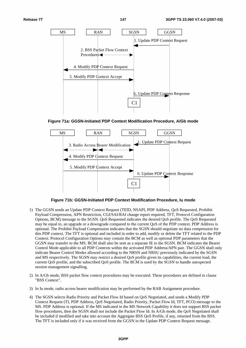
Release 7T 147 3GPP TS 23.060 V7.4.0 (2007-03)
GGSN
6. Update PDP Context Response
1. Update PDP Context Request
SGSNRANMS
4. Modify PDP Context Request
5. Modify PDP Context Accept
C1
2. BSS Packet Flow Context Procedures
Figure 71a: GGSN-Initiated PDP Context Modification Procedure, A/Gb mode
GGSN
6. Update PDP Context Response
1. Update PDP Context Request
SGSNRANMS
4. Modify PDP Context Request
5. Modify PDP Context Accept
3. Radio Access Bearer Modification
C1
Figure 71b: GGSN-Initiated PDP Context Modification Procedure, Iu mode
1) The GGSN sends an Update PDP Context Request (TEID, NSAPI, PDP Address, QoS Requested, Prohibit Payload Compression, APN Restriction, CGI/SAI/RAI change report required, TFT, Protocol Configuration Options, BCM) message to the SGSN. QoS Requested indicates the desired QoS profile. The QoS Requested may be equal to, an upgrade or a downgrade compared to the current QoS of the PDP context. PDP Address is optional. The Prohibit Payload Compression indicates that the SGSN should negotiate no data compression for this PDP context. The TFT is optional and included in order to add, modify or delete the TFT related to the PDP Context. Protocol Configuration Options may contain the BCM as well as optional PDP parameters that the GGSN may transfer to the MS. BCM shall also be sent as a separate IE to the SGSN. BCM indicates the Bearer Control Mode applicable to all PDP Contexts within the activated PDP Address/APN pair. The GGSN shall only indicate Bearer Control Modes allowed according to the NRSN and NRSU previously indicated by the SGSN and MS respectively. The SGSN may restrict a desired QoS profile given its capabilities, the current load, the current QoS profile, and the subscribed QoS profile. The BCM is used by the SGSN to handle unexpected session management signalling.
2) In A/Gb mode, BSS packet flow context procedures may be executed. These procedures are defined in clause "BSS Context".
3) In Iu mode, radio access bearer modification may be performed by the RAB Assignment procedure.
4) The SGSN selects Radio Priority and Packet Flow Id based on QoS Negotiated, and sends a Modify PDP Context Request (TI, PDP Address, QoS Negotiated, Radio Priority, Packet Flow Id, TFT, PCO) message to the MS. PDP Address is optional. If the MS indicated in the MS Network Capability it does not support BSS packet flow procedures, then the SGSN shall not include the Packet Flow Id. In A/Gb mode, the QoS Negotiated shall be included if modified and take into account the Aggregate BSS QoS Profile, if any, returned from the BSS. The TFT is included only if it was received from the GGSN in the Update PDP Context Request message.
3GPP

Release 7T 148 3GPP TS 23.060 V7.4.0 (2007-03)
Protocol Configuration Options contains the BCM as well as optional PDP parameters that the GGSN may transfer to the MS. Protocol Configuration Options is sent transparently through the SGSN. BCM indicates the Bearer Control Mode applicable to all PDP Contexts within the activated PDP Address/APN pair.
5) The MS should accept the PDP context modification requested by the network if it is capable of supporting any modified QoS Negotiated as well as any modified TFT. For a successful modification the MS acknowledges by returning a Modify PDP Context Accept message. If the MS is incapable of accepting a new QoS Negotiated or TFT it shall instead de-activate the PDP context with the PDP Context Deactivation Initiated by MS procedure.
NOTE: In order to facilitate operator control of the QoS an MS should accept a new QoS being assigned by the network even if the QoS is different from the one that the MS uses by default for a particular service type. One reason why the MS may not accept the modified QoS is if it has insufficient internal resources available to support the new QoS.
If the BCM parameter is not included in the Modify PDP Context Request message then the MS shall set the Bearer Control Mode to 'MS_only' for the PDP Address/APN pair (see clause 9.2).
6) Upon receipt of the Modify PDP Context Accept message, or upon completion of the RAB modification procedure, the SGSN returns an Update PDP Context Response (TEID, QoS Negotiated) message to the GGSN. If the SGSN receives a Deactivate PDP Context Request message, it shall instead follow the PDP Context Deactivation Initiated by MS procedure.
If an APN Restriction is received from the GGSN for this PDP Context, then the SGSN shall store this value for the PDP Context, replacing any previously stored value for this PDP context. The SGSN shall determine a (new) value for the Maximum APN Restriction using any stored APN Restriction and the received APN Restriction.
The CAMEL procedure calls shall be performed, see referenced procedure in TS 23.078 [8b]:
C1) CAMEL_GPRS_Change_Of_QoS.
The procedure returns as result "Continue".
9.2.3.3 MS-Initiated PDP Context Modification Procedure
The MS-Initiated PDP Context Modification procedure is illustrated in Figures 72a and 72b.
GGSN
3. Update PDP Context Response
2. Update PDP Context Request
SGSNRANMS
1. Modify PDP Context
6. Modify PDP Context Accept
C1
4. BSS Packet Flow Context Procedures
Figure 72a: MS-Initiated PDP Context Modification Procedure, A/Gb mode
3GPP

Release 7T 149 3GPP TS 23.060 V7.4.0 (2007-03)
GGSN
3. Update PDP Context Response
2. Update PDP Context Request
SGSN RANMS
1 . Modify PDP Context Request
6 . Modify PDP Context Accept
5. Radio Access Bearer Modification
C1
Figure 72b: MS-Initiated PDP Context Modification Procedure, Iu mode
1) The MS sends a Modify PDP Context Request (TI, QoS Requested, TFT, Protocol Configuration Options) message to the SGSN. Either QoS Requested or TFT or both may be included. QoS Requested indicates the desired QoS profile, while TFT indicates the TFT that is to be added or modified or deleted from the PDP context. Protocol Configuration Options may be used to transfer optional PDP parameters and/or requests to the GGSN.
2) The SGSN may restrict the desired QoS profile given its capabilities, the current load, and the subscribed QoS profile. The SGSN sends an Update PDP Context Request (TEID, NSAPI, QoS Negotiated, TFT, Protocol Configuration Options, serving network identity, CGI/SAI, CGI/SAI/RAI change support indication, DTI) message to the GGSN. If Direct Tunnel is established the SGSN provides to the GGSN the RNC's Address for User Plane and TEID for downlink data and shall include the DTI to instruct the GGSN to apply Direct Tunnel specific error handling as described in clause 13.8. The SGSN shall send the serving network identity to the GGSN. If QoS Negotiated and/or TFT received from the SGSN is incompatible with the PDP context being modified (e.g., TFT contains inconsistent packet filters), the GGSN rejects the Update PDP Context Request. The GGSN operator configures the compatible QoS profile. Protocol Configuration Options is sent transparently through the SGSN if received in Modify PDP Context Request message.
3) The GGSN may further restrict QoS Negotiated given its capabilities, operator policies and the current load or increase QoS Negotiated based on any external input (e.g. policy control). The GGSN stores QoS Negotiated, stores, modifies, or deletes TFT of that PDP context as indicated in TFT, and returns an Update PDP Context Response (TEID, QoS Negotiated, Protocol Configuration Options, Prohibit Payload Compression, APN Restriction, CGI/SAI/RAI change report required) message. Protocol Configuration Options may be used to transfer optional PDP parameters to the UE. The Prohibit Payload Compression indicates that the SGSN should negotiate no data compression for this PDP context. The SGSN shall re-verify and may restrict the QoS Negotiated received from the GGSN against the subscribed QoS profile and additionally restrict the QoS negotiated based on its capabilities and current load. The SGSN shall use this updated QoS Negotiated for the subsequent steps.
4) In A/Gb mode, BSS packet flow context procedures may be executed. These procedures are defined in clause "BSS Context".
5) In Iu mode, radio access bearer modification may be performed by the RAB Assignment procedure. In case the radio access bearer does not exist the RAB setup is done by the RAB Assignment procedure.
6) The SGSN selects Radio Priority and Packet Flow Id based on QoS Negotiated, and returns a Modify PDP Context Accept (TI, QoS Negotiated, Radio Priority, Packet Flow Id, Protocol Configuration Options) message to the MS. If the MS indicated in the MS Network Capability it does not support BSS packet flow procedures, then the SGSN shall not include the Packet Flow Id. In A/Gb mode, the QoS Negotiated shall take into account the Aggregate BSS QoS Profile, if any, returned from the BSS. Protocol Configuration Options is sent transparently through the SGSN if received in Modify PDP Context Response message.
If the MS is incapable of accepting the new QoS Negotiated, the MS should initiate application level signalling to lower the QoS requirements for the concerned application(s). If this is not possible then the MS shall instead de-activate the PDP context with the PDP Context Deactivation Initiated by the MS procedure.
NOTE 1: If the SGSN does not accept QoS Requested, then steps 2 and 3 of this procedure are skipped, and the existing QoS Negotiated is returned to the MS in step 4.
3GPP

Release 7T 150 3GPP TS 23.060 V7.4.0 (2007-03)
NOTE 2: In this release of the standards no procedure is defined that uses the Protocol Configuration Options in the PDP context modification procedure.
If an APN Restriction is received from the GGSN for this PDP Context, then the SGSN shall store this value for the PDP Context, replacing any previously stored value for this PDP context. The SGSN shall determine a (new) value for the Maximum APN Restriction using any stored APN Restriction and the received APN Restriction.
The CAMEL procedure calls shall be performed, see referenced procedure in TS 23.078 [8b]:
C1) CAMEL_GPRS_Change_Of_QoS.
The procedure returns as result "Continue".
9.2.3.4 RNC/BSS-Initiated PDP Context Modification Procedure
The RNC can request the release of the Iu connection (see clause "Iu Release Procedure"). The BSS may terminate the downlink data transfer to a MS by the Suspend procedure (which is triggered by the MS) or by the Radio Status procedure with cause "Radio contact lost with MS" or "Radio link quality insufficient to continue communication" both defined in TS 48.018 [78]. After Iu Release in Iu mode, or after termination of the downlink data transfer in A/Gb mode, the PDP contexts are modified as follows:
- In the SGSN, for a PDP context using background or interactive traffic class, the PDP context is preserved with no modifications.
- In the SGSN, for a PDP context using streaming or conversational traffic class, the PDP context is preserved, but the maximum bit rate is downgraded to 0 kbit/s (for both uplink and downlink). The SGSN sends an Update PDP Context Request (TEID, QoS Negotiated) message to the GGSN to set the maximum bit rate to 0 kbit/s in the GGSN. The value of 0 kbit/s for the maximum bit rate indicates to the GGSN to stop sending packets to the SGSN for this PDP context. For the Iu mode the value of 0 kbit/s for the maximum bit rate for both uplink and downlink indicates to the SGSN that a RAB shall not be re-established for this PDP Context in subsequent Service Request Procedure. For the A/Gb mode the value of 0 kbit/s for the maximum bit rate for both uplink and downlink indicates that the SGSN shall not send any downlink data for this PDP Context. In Iu and A/Gb mode CAMEL procedure calls shall be performed, see referenced procedure in TS 23.078 [8b]: CAMEL_GPRS_Change_Of_QoS. The procedure returns as result "Continue".
In Iu mode the following procedures shall be performed in the MS when radio coverage is lost:
- For a PDP context using background or interactive traffic class, the PDP context is preserved even if RRC re-establishment procedures have failed.
- For a PDP context using streaming or conversational traffic class, the PDP context is preserved, but the maximum bit rate is downgraded to 0 kbit/s (for both uplink and downlink) when the RRC re-establishment procedure has failed. After coverage is regained on the GERAN or the UTRAN and if the MS did not deactivate the PDP Context locally the MS should start MS-initiated PDP Context Modification procedure or the PDP Context Deactivation procedure. The MS shall use the PDP Context Modification procedure to re-activate the PDP context and re-establish the RAB .
In A/Gb mode the following procedures shall be performed in the MS when radio coverage is lost, when the radio link quality is insufficient or when the MS suspends GPRS:
- For a PDP context using background or interactive traffic class, the PDP context is preserved.
3GPP

Release 7T 151 3GPP TS 23.060 V7.4.0 (2007-03)
- For a PDP context using streaming or conversational traffic class, the PDP context is preserved, but the maximum bit rate is downgraded to 0 kbit/s (for both uplink and downlink). After coverage or radio link quality is regained on the GERAN or the UTRAN or when GPRS services shall resume and if the MS did not deactivate the PDP Context locally the MS should start MS initiated PDP Context Modification procedure or the PDP Context Deactivation procedure. The MS shall use the PDP Context Modification procedure to re-activate the PDP context.
9.2.3.5 RAB Release-Initiated Local PDP Context Modification Procedure
The RNC can request a RAB to be released through the RAB Release procedure without releasing the Iu connection.
After the RAB(s) release the SGSN shall modify the PDP context as follows:
- In the SGSN, for a PDP context using background or interactive traffic class, the PDP context is preserved with no modifications.
- In the SGSN, for a PDP context using streaming or conversational traffic class, the PDP context is preserved, but the maximum bit rate is downgraded to 0 kbit/s (for both uplink and downlink) when the associated RAB is released. The SGSN sends an Update PDP Context Request (TEID, QoS Negotiated) message to the GGSN to set the maximum bit rate to 0 kbit/s in the GGSN. The value of 0 kbit/s for the maximum bit rate indicates to the GGSN to stop sending packets to the SGSN on this PDP context. The value of 0 kbit/s for the maximum bit rate for both uplink and downlink indicates to the SGSN that a RAB shall not be re-established for this PDP Context in subsequent Service Request Procedure. CAMEL procedure calls shall be performed, see referenced procedure in TS 23.078 [8b]: CAMEL_GPRS_Change_Of_QoS. The procedure returns as result "Continue".
The following procedures shall be performed in the MS when the RRC layer indicate to higher layer that a RAB has been released and the RAB release was not initiated due to a PDP Context Deactivation Procedure:
- For a PDP context using background or interactive traffic class, the PDP context is be preserved with no modifications.
- For a PDP context using streaming or conversational traffic class, the PDP context is preserved, but the maximum bit rate is downgraded to 0 kbit/s (for both uplink and downlink).
At this point or at a later stage, the MS may start a PDP Context Deactivation procedure or PDP Context Modification procedure. The MS shall use the PDP context modification procedure to re-activate the PDP context and to re-establish the RAB.
9.2.3.6 RAN-initiated RAB Modification Procedure (Iu mode)
The RNC-initiated RAB Modification procedure permits an Iu mode RAN to propose modifications to any negotiable RAB parameter for an MS after RAB establishment, TS 25.413 [56b]. RAB parameters are equivalent to RAB attributes as defined in TS 23.107 [58] for each QoS class. The procedure is depicted in the figure below.
1. RAB Modify Request
RAN SGSN
2. SGSN initiated PDP Context Modification Procedure
MS GGSN
Figure 73: RAN-initiated RAB Modification Procedure
1) The RAN sends a RAB Modify Request (RAB ID, RAB Parameter Values) message to the SGSN.
2) The SGSN may decide to ignore the message or to invoke the PDP Context Modification procedure as described in clause 9.2.3.1, which includes the SGSN RAB Modification procedure.
3GPP

Release 7T 152 3GPP TS 23.060 V7.4.0 (2007-03)
9.2.4 Deactivation Procedures
9.2.4.1 MS Initiated PDP Context Deactivation Procedure
The PDP Context Deactivation Initiated by MS procedures for A/Gb mode and Iu mode are illustrated in Figure 74 and Figure 75, respectively.
GGSN
3. Delete PDP Context Response
3. Delete PDP Context Request
SGSN BSS MS
1. Deactivate PDP Context Request
4. Deactivate PDP Context Accept
C1
6. BSS Packet Flow Context Procedures
2. Security Functions
Figure 74: MS Initiated PDP Context Deactivation Procedure for A/Gb mode
GGSN
3. Delete PDP Context Response
3. Delete PDP Context Request
SGSNRANMS
1. Deactivate PDP Context Request
4. Deactivate PDP Context Accept
5. Radio Access Bearer Release
C1
Figure 75: MS Initiated PDP Context Deactivation Procedure for Iu mode
1) The MS sends a Deactivate PDP Context Request (TI, Teardown Ind) message to the SGSN.
2) In A/Gb mode security functions may be executed. These procedures are defined in clause "Security Function".
3) The SGSN sends a Delete PDP Context Request (TEID, NSAPI, Teardown Ind) message to the GGSN. If the MS in the Deactivate PDP Context Request message included Teardown Ind, then the SGSN deactivates all PDP contexts associated with this PDP address by including Teardown Ind in the Delete PDP Context Request message. The GGSN removes the PDP context(s) and returns a Delete PDP Context Response (TEID) message to the SGSN. If the MS was using a dynamic PDP address allocated by the GGSN, and if the context being deactivated is the last PDP context associated with this PDP address, then the GGSN releases this PDP address and makes it available for subsequent activation by other MSs. The Delete PDP Context messages are sent over the backbone network.
4) The SGSN returns a Deactivate PDP Context Accept (TI) message to the MS.
5) In Iu mode, radio access bearer release is done by the RAB Assignment procedure, if a RAB exists for this PDP context.
3GPP
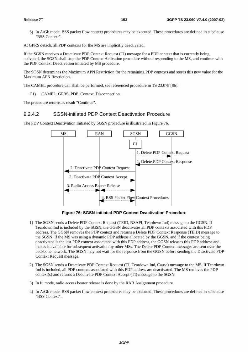
Release 7T 153 3GPP TS 23.060 V7.4.0 (2007-03)
6) In A/Gb mode, BSS packet flow context procedures may be executed. These procedures are defined in subclause "BSS Context".
At GPRS detach, all PDP contexts for the MS are implicitly deactivated.
If the SGSN receives a Deactivate PDP Context Request (TI) message for a PDP context that is currently being activated, the SGSN shall stop the PDP Context Activation procedure without responding to the MS, and continue with the PDP Context Deactivation initiated by MS procedure.
The SGSN determines the Maximum APN Restriction for the remaining PDP contexts and stores this new value for the Maximum APN Restriction.
The CAMEL procedure call shall be performed, see referenced procedure in TS 23.078 [8b]:
C1) CAMEL_GPRS_PDP_Context_Disconnection.
The procedure returns as result "Continue".
9.2.4.2 SGSN-initiated PDP Context Deactivation Procedure
The PDP Context Deactivation Initiated by SGSN procedure is illustrated in Figure 76.
GGSN
1. Delete PDP Context Response
1. Delete PDP Context Request
SGSN RAN MS
2. Deactivate PDP Context Request
2. Deactivate PDP Context Accept
3. Radio Access Bearer Release
C1
4. BSS Packet Flow Context Procedures
Figure 76: SGSN-initiated PDP Context Deactivation Procedure
1) The SGSN sends a Delete PDP Context Request (TEID, NSAPI, Teardown Ind) message to the GGSN. If Teardown Ind is included by the SGSN, the GGSN deactivates all PDP contexts associated with this PDP address. The GGSN removes the PDP context and returns a Delete PDP Context Response (TEID) message to the SGSN. If the MS was using a dynamic PDP address allocated by the GGSN, and if the context being deactivated is the last PDP context associated with this PDP address, the GGSN releases this PDP address and makes it available for subsequent activation by other MSs. The Delete PDP Context messages are sent over the backbone network. The SGSN may not wait for the response from the GGSN before sending the Deactivate PDP Context Request message.
2) The SGSN sends a Deactivate PDP Context Request (TI, Teardown Ind, Cause) message to the MS. If Teardown Ind is included, all PDP contexts associated with this PDP address are deactivated. The MS removes the PDP context(s) and returns a Deactivate PDP Context Accept (TI) message to the SGSN.
3) In Iu mode, radio access bearer release is done by the RAB Assignment procedure.
4) In A/Gb mode, BSS packet flow context procedures may be executed. These procedures are defined in subclause "BSS Context".
3GPP

Release 7T 154 3GPP TS 23.060 V7.4.0 (2007-03)
The SGSN determines the Maximum APN Restriction for the remaining PDP contexts and stores this new value for the Maximum APN Restriction.
The CAMEL procedure call shall be performed, see referenced procedure in TS 23.078 [8b]:
C1) CAMEL_GPRS_PDP_Context_Disconnection
The procedure returns as result "Continue".
9.2.4.3 GGSN-initiated PDP Context Deactivation Procedure
The PDP Context Deactivation Initiated by GGSN procedure is illustrated in Figure 77.
GGSN
3. Delete PDP Context Response
1. Delete PDP Context Request
SGSN RAN MS
2. Deactivate PDP Context Request
2. Deactivate PDP Context Accept
4. Radio Access Bearer Release
C1
5. BSS Packet Flow Context Procedures
Figure 77: GGSN-initiated PDP Context Deactivation Procedure
1) The GGSN sends a Delete PDP Context Request (TEID, NSAPI, Teardown Ind) message to the SGSN. Teardown Ind indicates whether or not all PDP contexts associated with this PDP address shall be deactivated.
2) The SGSN sends a Deactivate PDP Context Request (TI, Teardown Ind, Cause) message to the MS. If Teardown Ind was included by the SGSN, then all PDP contexts associated with this PDP address are deactivated. The MS removes the PDP context(s) and returns a Deactivate PDP Context Accept (TI) message to the SGSN.
3) The SGSN returns a Delete PDP Context Response (TEID) message to the GGSN. If the MS was using a dynamic PDP address allocated by the GGSN, and if the context being deactivated is the last PDP context associated with this PDP address, the GGSN releases this PDP address and makes it available for subsequent activation by other MSs. The Delete PDP Context messages are sent over the backbone network. The SGSN may not wait for the response from the MS before sending the Delete PDP Context Response message.
4) In Iu mode, radio access bearer release is done by the RAB Assignment procedure.
5) In A/Gb mode, BSS packet flow context procedures may be executed. These procedures are defined in subclause "BSS Context".
The SGSN determines the Maximum APN Restriction for the remaining PDP contexts and stores this new value for the Maximum APN Restriction.
The CAMEL procedure call shall be performed, see referenced procedure in TS 23.078 [8b]:
C1) CAMEL_GPRS_PDP_Context_Disconnection.
The procedure returns as result "Continue".
9.2.5 Preservation Procedures By sending a RAB Release Request or Iu Release Request message to the SGSN, an Iu mode RAN initiates the release of one or more RABs. The preservation procedure allows the active PDP contexts associated with the released RABs to be preservedin the CN, and the RABs can then be re-established at a later stage, see clause 9.2.5.2 and clause 9.2.3.5.
3GPP

Release 7T 155 3GPP TS 23.060 V7.4.0 (2007-03)
An Iu mode RAN uses the Iu Release Request to request release of all RABs of an MS, and the RAB Release Request in other cases.
9.2.5.1 Release of RABs Triggered by an Iu mode RAN
9.2.5.1.1 RAB Release Procedure
An Iu mode RAN initiates a RAB release procedure to release one or several RABs. The RAB Release procedure is described in clause 12.7.2.a.
9.2.5.1.2 Iu Release Procedure
An Iu mode RAN initiates an Iu release procedure to release all RABs of an MS and the Iu connection. The Iu Release procedure is described in clause 12.7.3.
9.2.5.2 Re-establishment of RABs
The procedure for re-establishment of RABs allows the SGSN to re-establish RABs for active PDP contexts that don't have an associated RAB.
The MS initiates the re-establishment of RABs by using the Service Request (Service Type = Data) message. This is described in the sub-clause "MS Initiated Service Request Procedure". SGSN shall not establish RABs for PDP contexts with maximum bit rate for uplink and downlink of 0 kbit/s. For these PDP contexts, the MS shall perform a MS-initiated PDP Context Modification or Deactivation procedure.
When RABs for an MS that has no RRC connection needs to be re-established, the CN must first page the MS. The clause "Network Initiated Service Request Procedure" describes this.
9.3 Packet Routeing and Transfer Function The packet routeing and transfer function:
- routes and transfers packets between a mobile TE and a packet data network, i.e. between reference point R and reference point Gi;
- routes and transfers packets between mobile TE and other GPRS PLMN, i.e. between reference point R and reference point Gi via interface Gp;
- routes and transfers packets between TEs, i.e. between the R reference point in different MSs; and
- optionally supports IP Multicast routeing of packets via a relay function in the GGSN.
The PDP PDUs shall be routed and transferred between the MS and the GGSN as N-PDUs. In case of PDP type PPP, the maximum size of each N-PDU shall be 1 502 octets. In other cases, the maximum size of each N-PDU shall be 1 500 octets. When the MS or the GGSN receives a PDP PDU that results in an N-PDU that is not larger than the maximum N-PDU size, the PDP PDU shall be routed and transferred as one N-PDU. When the MS or the GGSN receives a PDP PDU that results in an N-PDU that is larger than the maximum N-PDU size, the PDP PDU shall be segmented, discarded or rejected, depending on the PDP type and the implementation.
Between the 2G-SGSN and the MS, PDP PDUs are transferred with SNDCP. Between the 3G-SGSN and the MS, PDP PDUs are transferred with GTP-U and PDCP.
Between the SGSN and the GGSN, PDP PDUs are routed and transferred with the UDP/IP protocols. The GPRS Tunnelling Protocol transfers data through tunnels. A tunnel endpoint identifier (TEID) and a GSN address identify a tunnel.
When multiple PDP contexts exist for the same PDP address/APN pair of an MS, the GGSN routes downlink N-PDUs to the different GTP tunnels based on the downlink packet filters in the TFTs assigned to the PDP contexts. Upon reception of a PDP PDU, the GGSN evaluates for a match, first the downlink packet filter amongst all TFTs that has the smallest evaluation precedence index and, in case no match is found, proceeds with the evaluation of downlink packet filters in increasing order of their evaluation precedence index. This procedure shall be executed until a match is found, in which case the N-PDU is tunnelled to the SGSN via the PDP context that is associated with the TFT of the matching
3GPP

Release 7T 156 3GPP TS 23.060 V7.4.0 (2007-03)
downlink packet filter. If no match is found, the N-PDU shall be sent via the PDP context that does not have a TFT assigned to it; if all PDP contexts have a TFT assigned, the GGSN shall silently discard the PDP PDU.
When multiple PDP contexts exist for the same PDP address/APN pair of an MS, the MS routes uplink PDP-PDUs to the different PDP contexts based on either uplink packet filters in the TFTs assigned to these PDP contexts for 'NW_only' mode, MS-local mapping for 'MS_only' mode, or both for 'MS/NW' mode.
For 'MS_only' mode, upon transmission of a PDP PDU, the MS shall apply local mapping. The MS is responsible for creating or modifying PDP contexts and their QoS. The MS should define TFTs in such a way that downlink PDP PDUs are routed to a PDP context that best matches the QoS requested by the receiver of this PDU (e.g. an application supporting QoS). For each uplink PDP PDU, the MS should choose the PDP context that best matches the QoS requested by the sender of this PDP PDU (e.g. an application supporting QoS). Packet classification and routeing within the MS is an MS-local matter. The GGSN shall not match uplink N PDUs against TFTs.
For 'NW_only' mode, the MS evaluates for a match, first the uplink packet filter amongst all TFTs that has the smallest evaluation precedence index and, in case no match is found, proceeds with the evaluation of uplink packet filters in increasing order of their evaluation precedence index. This procedure shall be executed until a match is found or all uplink packet filters have been evaluated. If a match is found, the PDP PDU is transmitted on the PDP context that is associated with the TFT of the matching uplink packet filter. If no match is found, the PDP PDU shall be sent via the PDP context that has not been assigned a TFT including an uplink packet filter; if all PDP contexts have been assigned a TFT including an uplink packet filter, the MS shall silently discard the PDP PDU.
For 'MS/NW' mode, the MS evaluates for a match, first the uplink packet filter amongst all TFTs that has the smallest evaluation precedence index and, in case no match is found, proceeds with the evaluation of uplink packet filters in increasing order of their evaluation precedence index. This procedure shall be executed until a match is found, or all uplink packet filters have been evaluated. If a match is found, the PDP PDU is transmitted on the PDP context that is associated with the TFT of the matching uplink packet filter. If no match is found, the MS shall evaluate whether the PDP PDU belongs to an application for which the MS applied a local mapping to a PDP context. If this is the case, the relevant PDP context shall be used. Otherwise, the PDP PDU shall be sent via the PDP context that has not been assigned a TFT including an uplink packet filter. If all PDP contexts have been assigned a TFT including an uplink packet filter, the MS shall silently discard the PDP PDU.
TFTs are used for PDP types IP and PPP only. For PDP type PPP a TFT is applicable only when PPP is terminated in the GGSN (i.e. GGSN does not provide PDN interworking by means of tunnelled PPP, e.g. by the Layer Two Tunnelling Protocol (L2TP)) and IP traffic is carried over PPP. To support roaming subscribers, and for forward compatibility, the SGSN is not required to know the tunnelled PDP. Every SGSN shall have the capability to transfer PDUs belonging to PDPs not supported in the PLMN of the SGSN.
The GGSN could also optionally support IP Multicast: this allows the MSs to join multicast groups and start receiving multicast packets. The GGSN duplicates the incoming multicast packets and relays them to the already active TEIDs. These TEIDs are those of MSs that have joined a multicast group.
9.4 Relay Function The relay function of a network node transfers the PDP PDUs received from the incoming link to the appropriate outgoing link. At the RNC, the SGSN, and the GGSN the relay function stores all valid PDP PDUs until they are forwarded to the next network node or until the maximum holding time of the PDP PDUs is reached. The PDP PDUs are discarded when buffering is longer than their maximum holding time. This maximum holding time is implementation dependent and can be influenced by the PDP type, the QoS of the PDP PDU, the resource load status, and by buffer conditions. The discarding protects resources from useless transfer attempts, especially the radio resource. Impacts on user protocol operation by too short holding time shall be avoided.
In A/Gb mode, the SGSN and GGSN relay functions add sequence numbers to PDP PDUs received from SNDCP and from the Gi reference point, respectively. In Iu mode, the RNC and GGSN relay functions add sequence numbers to PDP PDUs received from PDCP and from the Gi reference point, respectively.
PDP PDUs may be re-sequenced in the RNC, the SGSN, and/or in the GGSN depending on the setting of the delivery order attribute in the QoS profile. In A/Gb mode, the SGSN relay function may perform re-sequencing of PDP PDUs before passing the PDP PDUs to SNDCP. In Iu mode, the SGSN relay function may optionally perform re-sequencing of PDP PDUs before passing the PDP PDUs to Iu GTP-U and before passing the PDP PDUs to Gn GTP-U. The GGSN relay function may perform re-sequencing of PDP PDUs before passing the PDP PDUs to the Gi reference point. The RNC may perform re-sequencing of PDP PDUs before passing the PDP PDUs to PDCP.
3GPP

Release 7T 157 3GPP TS 23.060 V7.4.0 (2007-03)
9.5 Packet Terminal Adaptation Function The Packet Terminal Adaptation function adapts packets received from and transmitted to the Terminal Equipment to a form suitable for transmission within the PLMN.
A range of MT versions providing different standard interfaces towards the TE can be used, e.g.:
- MT with asynchronous serial interface and PAD (Packet Assembly / Disassembly) support. In the case when the PAD function does not exist in the MT, it exists in the TE.
- "Embedded MT" integrated with the TE, possibly via an industry-standard application program interface.
- MT with synchronous serial interface.
9.6 Encapsulation Function GPRS transparently transports PDP PDUs between packet data networks and MSs. All PDP PDUs are encapsulated and decapsulated for routeing purposes. Encapsulation functionality exists at the MS, at the RNC, at the Iu mode BSC, at the SGSN, and at the GGSN. Encapsulation allows PDP PDUs to be delivered to and associated with the correct PDP context in the MS, the SGSN, or the GGSN. Two different encapsulation schemes are used; one for the backbone network between two GSNs and between an SGSN and an RNC, and one for the A/Gb mode connection between the SGSN and the MS or for the Iu mode RRC connection between the RAN and the MS.
Encapsulation requires that the MS is attached to GPRS, and that the PDP Context Activation procedure has been executed. If the GPRS Attach or PDP Context Activation procedures cannot be successfully executed, then uplink PDP PDUs are discarded in the MS. If these procedures have not been executed when a downlink PDP PDU arrives in the GGSN, then the downlink PDP PDU shall be discarded, rejected, or the Network-Requested PDP Context Activation procedure shall be initiated.
9.6.1 Encapsulation Between GSNs The GPRS packet domain PLMN backbone network encapsulates a PDP PDU with a GPRS Tunnelling Protocol header, and inserts this GTP PDU in a UDP PDU that again is inserted in an IP PDU. The IP and GTP PDU headers contain the GSN addresses and tunnel endpoint identifier necessary to uniquely address a GSN PDP context.
9.6.2 Encapsulation Between SGSN and RAN in Iu mode On the Iu interface, a PDP PDU is encapsulated with a GPRS Tunnelling Protocol header.
9.6.3 Encapsulation Between SGSN and MS in A/Gb mode Between an SGSN and an MS in A/Gb mode, an SGSN or MS PDP context is uniquely addressed with a temporary logical link identity and a network layer service access point identifier pair. TLLI is derived from the P-TMSI. An NSAPI is assigned when the MS initiates the PDP Context Activation function. The relationship between TLLI / NSAPI and LLC / SNDCP is illustrated in Figure 94. TLLI and NSAPI are described in clause "NSAPI and TLLI for A/Gb mode".
9.6.4 Encapsulation Between RAN and MS in Iu mode On the Uu interface, a PDP PDU is encapsulated with PDCP.
10 Message Screening Functionality This screening mechanism may be performed by routers and firewalls, and performs the selection of which packets to allow and which to deny.
3GPP

Release 7T 158 3GPP TS 23.060 V7.4.0 (2007-03)
Only network-controlled message screening shall be supported. Network-controlled screening is used to protect the GPRS packet domain PLMN from known security problems, and the screening provided by a certain PLMN is applied independently of the MS user. Network-controlled screening is outside the scope of this specification.
11 Compatibility Issues Non-GPRS MSs in A/Gb mode PLMNs that support GPRS shall, without changes, be able to continue operation.
PLMNs that do not support GPRS shall, without changes, be able to continue interworking with PLMNs that do support GPRS.
An A/Gb mode MS shall be able to access GPRS services with GPRS-aware SIMs, and with SIMs that are not GPRS-aware. A GPRS-aware SIM is able to store information in the elementary files EFKcGPRS and EFLOCIGPRS, as defined in TS 51.011 [28].
The compatibility of SIMs and USIMs with A/Gb mode MSs or Iu mode MSs is defined in TS 22.102.
11.1 Interaction between Releases 97/98 and 99 NOTE: Unless specifically indicated, references to release 97 in this clause refer to both release 97 and
release 98.
11.1.1 Interactions Between GTP v0 (R97) and GTP v1 (R99) When a first GSN receives a GTP PDU from a second GSN using a version not supported, then the first GSN shall return a "version not supported" error message to the second GSN. The second GSN shall then fall back to the most-recent version supported by the first GSN. A GSN shall use its most-recent GTP version when initiating GTP PDU transmission to a new GSN.
When an SGSN that supports GTP v1 establishes a GTP tunnel to a GGSN that supports GTP v0, the SGSN shall convert a release 99 QoS profile to a release 97 QoS profile before transmitting the QoS profile to the GGSN. If the MS supports the R99 QoS profile, the SGSN shall convert the negotiated R97 QoS profile to an R99 QoS profile before transmitting the QoS profile to the MS.
A GGSN shall be able to fall back to GTP v0 during an Update PDP Context procedure. That is, the GGSN shall accept an Update PDP Context Request of GTP v0 even if the established GTP tunnel is of GTP v1.
When an inter-SGSN RA update procedure is performed from a first SGSN that supports GTP v1 to a second SGSN that supports GTP v0, the first SGSN shall convert the R99 QoS profile to an R97 QoS profile before sending the SGSN Context Response message. Furthermore, it fills the Uplink Flow Label Signalling field in the PDP Context information element of the SGSN Context Response message with the lower two octets of the Uplink TEID Control Plane. All PDP contexts that are identified by an extended TI (see TS 24.007 [12]) and all PDP contexts with a maximum bitrate for uplink and downlink of 0 kbit/s shall be deleted locally in the MS and the first SGSN. The first SGSN shall initiate the deletion of these PDP contexts in the GGSN after receiving an SGSN Context Acknowledge message from the second SGSN. If several of the remaining PDP contexts have been activated for the same APN and PDP address in the first SGSN (secondary PDP context activation), then all PDP contexts except the PDP context with the highest-quality QoS profile shall be deleted locally in the MS and in the first SGSN, and the first SGSN shall initiate the deletion of these PDP contexts in the GGSN.
The MS detects that the new SGSN is supporting only GTPv0 from the Release Indication broadcasted by the RAN.
TS 23.107 [58] specifies how to determine the highest-quality QoS profile. The second SGSN shall be responsible for updating the remaining PDP context in the GGSN, and the GGSN shall remove the TFT if present when it receives the GTP v0 Update PDP Context Request message.
NOTE: The conversion between an R99 QoS profile and an R97 QoS profile is defined in TS 23.107 [58].
When an inter-SGSN RA update procedure is performed from a first SGSN that supports GTP v0 to a second SGSN that supports GTP v1, the second SGSN shall convert the R97 QoS profile to the R99 QoS profile, ignore the delivered Uplink Flow Label Signalling and use GTP v1 to send the Update PDP Context Request message to the GGSN. The
3GPP

Release 7T 159 3GPP TS 23.060 V7.4.0 (2007-03)
Update PDP Context Request message shall be sent with a header containing a TEID set to all zeros and with an additional IE containing the IMSI for the PDP context.
A GGSN shall be able to change to GTP v1 during an Update PDP Context procedure. That is, the GGSN shall accept an Update PDP Context Request of GTP v1 with a TEID set to all zeros and containing the IMSI in addition to the NSAPI, even if the established GTP tunnel is of GTP v0.
When a GTP v0 tunnel was established between the old SGSN and the GGSN, and both old and new SGSNs support GTPv1 the respective uplink Flow Label signalling shall be inserted in the two lower octets of the Uplink TEID Control Plane field of the SGSN Context Response message; the upper two octets shall be set to all zeros.
When an inter-SGSN RA update procedure is performed from a first SGSN that supports only GTP v0 to a second SGSN that supports GTP v1, and the second SGSN does not have a valid PDP Context Identifier, it shall use value 255 to indicate this.
11.1.2 Interactions Between MS R97 and CN R99 When an R97 MS activates a PDP context and both the SGSN and the GGSN support R99, the QoS profile shall not be converted to R99.
11.1.3 Interactions Between SM R97 and SM R99 The SM protocol shall be backwards compatible.
11.1.4 Interactions Between MAP R97 and MAP R99 The MAP protocol shall be backwards compatible to allow interworking between HLRs and SGSNs that support different releases.
12 Transmission
12.1 Transmission Modes In A/Gb mode, the LLC and RLC protocols offer various transmission modes. The combinations of the LLC and RLC transmission modes define the QoS attributes SDU error ratio and residual bit error ratio.
In Iu mode, the RLC protocol provides various transmission modes to support user data transmission with different QoS.
The RLC protocol for A/Gb mode and the RLC protocol for Iu mode are distinct protocols.
12.1.1 GTP-U Transmission Modes One mode of operation of the GTP-U layer is supported for information transfer between the GGSN and SGSN; unacknowledged (UDP/IP). In Iu mode, GTP-U is also used on the Iu interface for user data transport. Only the unacknowledged mode (UDP/IP) is supported on the Iu interface.
12.1.2 LLC Transmission Modes (A/Gb mode) Two modes of operation of the LLC layer are defined for information transfer; unacknowledged and acknowledged. The LLC layer shall support both modes simultaneously.
- In acknowledged mode, the receipt of LL-PDUs is confirmed. The LLC layer retransmits LL-PDUs if confirmation has not been received within a timeout period.
- In unacknowledged mode, there is no confirmation required for LL-PDUs.
Signalling and SMS shall be transferred in unacknowledged mode.
3GPP

Release 7T 160 3GPP TS 23.060 V7.4.0 (2007-03)
In unacknowledged mode, the LLC layer shall offer the following two options:
- transport of "protected" information, such that errors within the LLC information field result in the frame being discarded; and
- transport of "unprotected" information, such that errors within the LLC information field do not result in the frame being discarded.
The LLC layer shall support several different QoS traffic classes with different transfer delay characteristics.
12.1.3 RLC Transmission Modes Two modes of operation of the RLC layer are defined for information transfer; unacknowledged and acknowledged. The RLC layer shall support both modes simultaneously.
The RLC for A/Gb mode is described in TS 44.060 [77], and for Iu mode in TS 25.322 [55].
12.2 Logical Link Control Functionality (A/Gb mode) The Logical Link Control (LLC) protocol provides a reliable logical link between the MS and its SGSN. As shown in clause "User and Control Planes", the LLC layer is situated below the SNDC layer.
12.2.1 Addressing TLLI is used for addressing at the LLC layer. TLLI is described in clause "NSAPI and TLLI for A/Gb mode".
12.2.2 Services LLC provides the services necessary to maintain a ciphered data link between an MS and an SGSN. The LLC layer does not support direct communication between two MSs.
The LLC connection is maintained as the MS moves between cells served by the same SGSN. When the MS moves to a cell being served by a different SGSN, the existing connection is released and a new logical connection is established with the new SGSN.
LLC shall be independent of the underlying radio interface protocols. In order to allow LLC to operate with a variety of different radio interface protocols, and to ensure optimum performance, it may be necessary to adjust e.g. the maximum LLC PDU length and the LLC protocol timer values. Such adjustments can be made through negotiation between the MS and the SGSN. The maximum length of an LLC PDU shall not be greater than 1 600 octets minus the BSSGP protocol control information.
12.2.3 Functions The Logical Link Control layer supports:
- service primitives allowing the transfer of SNDCP Protocol Data Units (SN-PDUs) between the Subnetwork Dependent Convergence layer and the Logical Link Control layer;
- procedures for transferring LL-PDUs between the MS and SGSN, including:
- procedures for unacknowledged delivery of LL-PDUs between the MS and the SGSN; and
- procedures for acknowledged, reliable delivery of LL-PDUs between the MS and SGSN;
- procedures for detecting and recovering from lost or corrupted LL-PDUs;
- procedures for flow control of LL-PDUs between the MS and the SGSN; and
- procedures for ciphering of LL-PDUs. The procedures are applicable to both unacknowledged and acknowledged LL-PDU delivery.
3GPP

Release 7T 161 3GPP TS 23.060 V7.4.0 (2007-03)
The layer functions are organised in such a way that ciphering resides immediately above the RLC/MAC layer in the MS, and immediately above the BSSGP layer in the SGSN.
12.3 Subnetwork Dependent Convergence Functionality (A/Gb mode)
The Subnetwork Dependent Convergence (SNDC) protocol is situated below the network layer and above the Logical Link Control layer in the MS and the SGSN, as shown in clause "User and Control Planes". A variety of network layers are supported; e.g. IP. The network-layer packet data protocols share the same SNDCP, which performs multiplexing of data coming from the different sources to be sent across the LLC. This is illustrated in Figure 80.
Packet DataProtocol
SNDCP
LLC Information
Signalling SMS
LLC
NSAPI
NSAPI + Control
DataControl
SNDC Header
LLC HeaderTLLI
RLC or BSSGP
Data
N-PDU
SAPI
Figure 80: Multiplexing of Network Protocols
The following identities and control information is needed:
- NSAPI identifies the network layer. The SNDCP control part contains compression information.
- TLLI identifies the MS. The LLC control part contains the rest of the LLC protocol header including ciphering information.
The Subnetwork Dependent Convergence function is defined in terms of offered services and sub-functions.
12.3.1 Services The SNDC function provides the following services to the network layer:
- Transmission and reception of N-PDUs in acknowledged and unacknowledged LLC mode. In acknowledged mode, the receipt of data shall be confirmed at the LLC layer, and the data shall be transmitted and received in order per NSAPI. In unacknowledged mode, the receipt of data shall not be confirmed at the SNDCP layer nor at the LLC layer.
- Transmission and reception between the MS and SGSN of variable-length N-PDUs.
- Transmission and reception of N-PDUs between the SGSN and MS according to the negotiated QoS profile.
- Transfer of the minimum amount of data possible between the SGSN and MS through compression techniques.
The SNDC function requires the following services from the LLC layer:
- Acknowledged and unacknowledged data transfer.
3GPP

Release 7T 162 3GPP TS 23.060 V7.4.0 (2007-03)
- Ciphered transmission of SN-PDUs.
- In-order delivery of SN-PDUs per LLC SAPI.
- Support for variable-length SN-PDUs.
12.3.2 Subfunctions
Compression
Segmentation Reassembly
De-compression
SNDC Primitive SNDC Primitive
LLC Primitive LLC Primitive
Network Layer
SNDC Layer
LLC Layer
Figure 81: Sequential Invocation of SNDC Functionality
SNDCP performs the following subfunctions:
- Mapping of SNDC primitives received from the network layer into corresponding LLC primitives to be passed to the LLC layer, and vice versa.
- Multiplexing of N-PDUs from one or several NSAPIs onto one LLC SAPI. NSAPIs that are multiplexed onto the same SAPI shall use the same radio priority level, and traffic class. In case BSS packet flow contexts are created all NSAPIs that are multiplexed onto the same LLC SAPI shall share the same BSS packet flow context.
- Compression of redundant protocol control information and user data. This may include e.g. TCP/IP header compression and V.42 bis [32] data compression. Compression may be performed independently for each QoS traffic handling priority and traffic class. If several network layers use the same QoS traffic handling priority and traffic class, one common compressor may be used for these network layers. The relationship between NSAPIs, compressors, and SAPIs is defined in TS 44.065 [16]. Compression parameters are negotiated between the MS and the SGSN. Compression is an optional SNDC function. The GGSN may indicate to the SGSN during PDP Context Activation and during Update PDP Context to negotiate no data compression for the PDP context.
- Segmentation and reassembly. The output of the compression subfunctions are segmented to maximum-length LLC frames.
12.4 PDCP (Iu mode) The Packet Data Compatibility Protocol (PDCP) transmission functionality maps network-level characteristics onto the characteristics of the underlying network. PDCP can support several network layer protocols by providing protocol transparency for the users of the service. PDCP provides protocol control information compression. PDCP is located in the MS and the RAN and is described in TS 25.323 [57].
12.5 Point-to-Point Protocol Functionality The PPP protocol is specified in RFC 1661 [44].
12.5.1 User Plane for PDP Type PPP The user plane for the PDP type PPP consists of a PPP protocol stack above SNDCP for A/Gb mode or above PDCP for Iu mode in the MS, and above GTP in the GGSN. The GGSN may either terminate the PPP protocol and access the packet data network at the IP level, or further tunnel PPP PDUs via e.g. L2TP.
3GPP
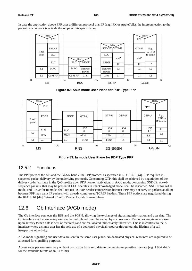
Release 7T 163 3GPP TS 23.060 V7.4.0 (2007-03)
In case the application above PPP uses a different protocol than IP (e.g. IPX or AppleTalk), the interconnection to the packet data network is outside the scope of this specification.
Relay
NetworkService
GTP-USNDCP
LLC
RLC
MAC
GSM RF
SNDCP
LLC
BSSGP
L1bis
RLC
MAC
GSM RF
BSSGP
L1bis
Relay
L2
L1
IP
L2
L1
IP
GTP-U
Um Gb Gn GiMT BSS SGSN GGSN
NetworkService
UDPUDP
E.g.,L2TP orIP tunnel
R
RelayPPP
R ref.point
RelayPPP
L1
L2 L2
L1
IP
Figure 82: A/Gb mode User Plane for PDP Type PPP
ATM
PDCP PDCP
L1bisL1bis
L2
L1
L2
L1
UDPIP
GTP-U
Uu Iu Gn GiMS RNS 3G-SGSN GGSN
ATM
UDPIP
UDPIP
GTP-UGTP-UGTP-U
UDPIP
PPP
RLC RLC
MAC MAC
L1L1
Relay
R
Relay
PPP
R ref.point
L1
L2
E.g.,L2TP orIP tunnel
L2
L1
IP
Figure 83: Iu mode User Plane for PDP Type PPP
12.5.2 Functions The PPP peers at the MS and the GGSN handle the PPP protocol as specified in RFC 1661 [44]. PPP requires in-sequence packet delivery by the underlying protocols. Concerning GTP, this shall be achieved by negotiation of the delivery order attribute in the QoS profile upon PDP context activation. In A/Gb mode, concerning SNDCP, out-of-sequence packets, that may be present if LLC operates in unacknowledged mode, shall be discarded. SNDCP for A/Gb mode, and PDCP for Iu mode, shall not use TCP/IP header compression because PPP may not carry IP packets at all, or because PPP may carry IP packets with already compressed TCP/IP headers. These PPP options are negotiated during the RFC 1661 [44] Network Control Protocol establishment phase.
12.6 Gb Interface (A/Gb mode) The Gb interface connects the BSS and the SGSN, allowing the exchange of signalling information and user data. The Gb interface shall allow many users to be multiplexed over the same physical resource. Resources are given to a user upon activity (when data is sent or received) and are reallocated immediately thereafter. This is in contrast to the A interface where a single user has the sole use of a dedicated physical resource throughout the lifetime of a call irrespective of activity.
A/Gb mode signalling and user data are sent in the same user plane. No dedicated physical resources are required to be allocated for signalling purposes.
Access rates per user may vary without restriction from zero data to the maximum possible line rate (e.g. 1 984 kbit/s for the available bitrate of an E1 trunk).
3GPP

Release 7T 164 3GPP TS 23.060 V7.4.0 (2007-03)
12.6.1 Physical Layer Protocol Several physical layer configurations and protocols are possible, as defined in TS 48.014 [19].
The physical resources shall be allocated by O&M procedures.
12.6.2 Link Layer Protocols Several Gb interface link layer configurations and protocols are possible as defined in TS 48.016 [20].
12.6.3 BSS GPRS Protocol The primary function of BSSGP is to provide the radio-related, QoS, and routeing information that is required to transmit user data between a BSS and an SGSN. In the BSS, it acts as an interface between LLC frames and RLC/MAC blocks. In the SGSN, it forms an interface between RLC/MAC-derived information and LLC frames. A secondary function is to enable two physically distinct nodes, the SGSN and the BSS, to operate node management control functions.
GbBSS
NetworkService
RLC
MAC
BSSGP
L1
Relay
LLC
BSSGP
L1
SGSN
NetworkService
Figure 84: BSSGP Protocol Position
There is a one-to-one relationship between the BSSGP protocol in the SGSN and in the BSS. If one SGSN handles multiple BSSs, the SGSN has to have one BSSGP protocol machine for each BSS. If the BSS applies Intra Domain Connection of RAN Nodes to Multiple CN Nodes, the BSS must have one BSSGP protocol machine for each SGSN to which it applies Intra Domain Connection of RAN Nodes to Multiple CN Nodes.
The main functions of the BSSGP protocol are to:
- provide a connection-less link between the SGSN and the BSS;
- transfer data unconfirmed between the SGSN and the BSS;
- provide tools for bi-directional control of the flow of data between the SGSN and the BSS;
- handle paging requests from the SGSN to the BSS;
- give support for flushing of old messages in the BSS e.g. when an MS changes BSS;
- support multiple layer 2 links between the SGSN and one BSS; and
- Provide tools for control of the flow of data between the SGSN and the BSS during PS Handover procedures, as defined in TS 48.018 [78].
BSSGP is defined in TS 48.018 [78].
12.6.3.1 Inter-dependency of the BSSGP and LLC Functions
The functions of the BSSGP shall be defined in the context of the LLC function in order to avoid duplication of functions and information flows. The following functional model indicates each layer's functional responsibilities.
3GPP

Release 7T 165 3GPP TS 23.060 V7.4.0 (2007-03)
Table 4: Mapping of High-level Functions Across the Gb Architecture
Network Node and Function
MS BSS SGSN
LLC: TS 44.064 [15]
Same as for the SGSN.
Provides transfer of frames between the SGSN and MS.
BSSGP: TS 48.018 [78]
MS←PLMN: Using BSSGP information, RLC/MAC operations are invoked. MS→PLMN: Using RLC/MAC-derived information, a BSSGP PDU is constructed. An identifier of the cell including RAC and LAC in which an LLC frame was received is inserted into the BSSGP PDU. Same as for SGSN.
Individual MS radio-related information is used by the BSS to transfer LLC frames across the Gb and Um. Provides flow control and unconfirmed data delivery services across the Gb interface (not the Um – this is the function of the LLC and RLC/MAC function). Provides SGSN-BSS node management functions.
Network Service: TS 48.016 [20]
Same as for SGSN Provides a multiplexing, variable-bandwidth, frame-based, link layer transport mechanism across the Gb interface, and load balancing.
12.6.3.2 BSSGP Addressing
For information transfer between the SGSN and the BSS, the BSSGP is using a BSSGP Virtual Connection Identifier (BVCI) for addressing. Additionally, QoS profile, and the MS identification, e.g. TLLI, may be used to create queues and contexts in both the SGSN and the BSS. The flow control mechanism is then based on these queues and contexts.
12.6.3.3 BVCI Contexts in BSS and in SGSN
A BVCI context in the BSS consists of at least one queue for LLC PDUs and of the radio resource capacity that is available on a radio cell for one SGSN. If the BSS applies Intra Domain Connection of RAN Nodes to Multiple CN Nodes, the BSS must share the total available radio resource capacity for a radio cell between all the BVCI contexts representing this radio cell, where each of these BVCI contexts represents the radio cell for one SGSN.
The BVCI context in the BSS is allocated for each cell supporting GPRS. For each new GPRS cell introduced in the BSS area, a new BVCI context shall be allocated. If the BSS applies Intra Domain Connection of RAN Nodes to Multiple CN Nodes, the BSS must have for each cell supporting GPRS and belonging to one pool area, one BVCI context for each of the SGSNs associated with this pool area.
In the SGSN, the BVCI context consists of at least one queue for LLC PDUs and the allowed throughput on BSSGP. The allowed throughput is updated by BSSGP flow control messages.
12.6.3.4 Flow Control Between SGSN and BSS over the Gb Interface
The flow control mechanism controls the loading of the BSS LLC PDU queues per BVCI, per MS and optionally per one or more PFCs between the SGSN and the BSS in the downlink direction. No flow control is performed in the uplink direction. Buffers and link capacity shall be dimensioned to avoid loss of uplink data.
3GPP

Release 7T 166 3GPP TS 23.060 V7.4.0 (2007-03)
The downlink flow control mechanism is based on the following principles:
- In the SGSN, queues for LLC PDUs are provided per BVCI. These queues may be split further, e.g. per MS or per packet flow. The SGSN shall pass LLC PDUs to LLC via BSSGP to the BSS as long as the allowed BSSGP throughput is not exceeded. The allowed BSSGP throughput is given per BVCI, for a single MS on that BVCI and optionally for one or more PFCs of a single MS on a certain BVCI. The SGSN schedules the BSSGP downlink traffic of all MSs of a BVCI and, optionally of all PFCs of an MS, according to the maximum and guaranteed bitrate attributes and to the QoS profile related to each LLC PDU. The scheduling algorithm is implementation dependent.
- In the BSS, queues per BVCI context are provided at the BSSGP level. These queues may be split further, e.g. per MS or per packet flow. Depending on the queuing conditions and the available radio resource capacity in the cell, the BSS indicates the allowed BSSGP throughput per BVCI context and the default allowed BSSGP throughput for each individual MS of that BVCI context by BSSGP flow control messages to the SGSN. Additionally, the BSS may change the allowed BSSGP throughput for one or more PFCs of an individual MS or for an individual MS by a BSSGP flow control message. As more than one SGSN may send downlink data at the same time for a radio cell when the BSS applies Intra Domain Connection of RAN Nodes to Multiple CN Nodes, the BSS has to share the total possible downlink traffic between the SGSNs that can access a radio cell. The BSS should use the existing flow control procedure on BVCI level to control each of the SGSNs in a way not to violate the total possible traffic for the radio cell. How the BSS decides to share the downlink traffic between each of the SGSNs is an implementation specific issue.
12.6.3.5 BSS Context
The SGSN may provide a BSS with information related to ongoing user data transmission in A/Gb mode. The information is given as BSS packet flow contexts, which describe QoS characteristics for the data transmission. Network support of BSS packet flow procedures is indicated in the system information as specified in TS 44.060 [77], the MS support is indicated in MS network capability as specified in TS 24.008 [13].
All BSS packet flow contexts related to one MS are stored in an MS specific BSS context. The BSS may contain BSS contexts for several MSs. Within a BSS context the BSS packet flow contexts are identified by a packet flow identifier, which is assigned by the SGSN. A BSS packet flow context is shared by one or more LLC SAPIs of the same MS with identical or similar negotiated QoS profiles. The data transfers related to LLC SAPIs that share the same BSS packet flow context constitute one packet flow.
Four packet flows are pre-defined, and identified by four reserved packet flow identifier values. The BSS shall not negotiate BSS packet flow contexts for these pre-defined packet flows with the SGSN. One pre-defined packet flow is used for best-effort service, one is used for SMS, one is used for TOM (Tunnelling of Messages) and one is used for signalling. The SGSN can assign the best-effort or SMS packet flow identifier to any PDP context. In the SMS case, the BSS shall handle the packet flow for the PDP context with the same QoS with which it handles SMS. A non-reserved packet flow identifier value is only significant for an MS when the SGSN provided the BSS with a packet flow context for this packet flow identifier value for this MS.
The combined BSS QoS profile for the PDP contexts that share the same packet flow is called the aggregate BSS QoS profile. The aggregate BSS QoS profile is considered to be a single parameter with multiple data transfer attributes as defined in subclause "Quality of Service Profile". It defines the QoS that must be provided by the BSS for a given packet flow between the MS and the SGSN, i.e. for the Um and Gb interfaces combined. The aggregate BSS QoS profile is negotiated between the SGSN and the BSS.
A BSS packet flow timer indicates the maximum time that the BSS may store the BSS packet flow context. The BSS packet flow timer shall not exceed the value of the READY timer for this MS. The BSS packet flow timer is started when the BSS packet flow context is stored in the BSS and when an LLC frame is received from the MS. When the BSS packet flow timer expires, the BSS shall delete the BSS packet flow context.
When a PDP context is activated, modified or deactivated, the SGSN may create, modify, or delete BSS packet flow contexts.
PS Handover procedure is used to handover an MS with one or more packet flows from a source cell to a target cell. Handling of the BSS packet flows during PS Handover procedures over the BSSGP are described in TS 43.129 [87] and TS 48.018 [78].
3GPP

Release 7T 167 3GPP TS 23.060 V7.4.0 (2007-03)
12.6.3.5.1 BSS Packet Flow Context Creation Procedure
On receiving a request to transmit an uplink or downlink LLC PDU for which no BSS packet flow context exists in the BSS, the BSS may request the download of the BSS packet flow context from the SGSN.
If MS and BSS supports BSS packet flow procedures the SGSN may at any time request the creation of a BSS packet flow context, e.g. due to the activation of a PDP context.
If a request to create a BSS Packet Flow is received in the BSS for an MS during the ongoing PS Handover procedure, then the BSS shall ignore the request and apply the procedures as described in TS 48.018 [78].
The BSS Packet Flow Context Creation procedure is illustrated in Figure 85.
2. Create BSS Packet Flow Context Request
3. Create BSS Packet Flow Context Accept
BSS SGSN
1. Download BSS Packet Flow Context Request
Figure 85: BSS Packet Flow Context Creation Procedure
1) The BSS receives a request to transfer an uplink or downlink user data LLC PDU for which it currently does not have a BSS packet flow context. In the uplink case, TLLI, Radio Priority, and Packet Flow Id are received from the MS as defined in TS 44.060 [77]. In the downlink case, TLLI and Packet Flow Id are received from the SGSN as defined in TS 48.018 [78]. If Packet Flow Id does not indicate a pre-defined value the BSS sends a Download BSS Packet Flow Context Request (RAI, TLLI, Packet Flow Id) message to the SGSN. Until the BSS receives the BSS packet flow context, the BSS shall handle uplink and downlink transfers according to a default aggregate BSS QoS profile. For uplink transfers, the default profile is specific to the radio priority level.
2) The SGSN sends a Create BSS Packet Flow Context Request (IMSI, TLLI, Packet Flow Id, Aggregate BSS QoS Profile Requested, BSS Packet Flow Timer) message to the associated BSS. The SGSN derives Aggregate BSS QoS Profile Requested from the QoS profile negotiated for the PDP contexts that share a packet flow as follows: The SGSN shall divide the transfer delay attribute in the QoS profile in one core network part and one BSS part. The SGSN estimates the transfer delay in the core network and subtracts this from the GPRS bearer service transfer delay. The result only covers the delay in the MS to SGSN segment of the GPRS PLMN. Since the BSS transports LLC PDUs obtained after segmentation of SDUs by the SNDCP layer, the SGSN shall convert the values of the GPRS bearer service attributes maximum SDU size, SDU error ratio, residual bit error ration, maximum bit rate, guaranteed bit rate and the resulting transfer delay to values applicable to the LLC PDUs. All other attributes in Aggregate BSS QoS Profile shall be the same as the corresponding GPRS bearer service attribute, see TS 23.107 [58]. The SGSN may also include the Allocation / Retention Priority Information Element in the Create BSS Packet Flow Context Request.
3) The BSS may restrict the requested aggregate BSS QoS profile given its capabilities and the current load. If the Allocation / Retention Priority Information Element is included by the SGSN in the Create BSS Packet Flow Context Request, the BSS may use it to perform queuing of the packet flow context creation or to pre-empt other packet flow contexts. The BSS creates a BSS packet flow context and inserts the parameters in its BSS context. The BSS returns a Create BSS Packet Flow Context Accept (IMSI, Packet Flow Id, Aggregate BSS QoS Profile Negotiated) message to the SGSN. The BSS uses the negotiated aggregate BSS QoS profile when allocating radio resources and other resources such as buffer capacity. The detailed operation is defined in TS 48.018 [78]. If the SGSN Aggregate BSS QoS Profile requested by the SGSN was restricted by the BSS, the SGSN takes the BSS restriction into account when indicating to the MS the negotiated QoS of the associated PDP context(s).
12.6.3.5.2 SGSN-Initiated BSS Packet Flow Context Modification Procedure
The SGSN may at any time request the modification of the contents of an existing BSS packet flow context, e.g. due to the activation, modification, or deactivation of a PDP context. The BSS Packet Flow Context Creation procedure shall be used in this case, and the BSS shall instead of creating a BSS packet flow context overwrite the existing parameters with the modified parameters.
3GPP

Release 7T 168 3GPP TS 23.060 V7.4.0 (2007-03)
The BSS Packet Flow Context Modification procedure will never be initiated for an MS during the ongoing PS Handover procedure as described in TS 48.018 [78].
12.6.3.5.3 BSS-Initiated BSS Packet Flow Context Modification Procedure
The BSS can at any time request modification of the contents of an existing BSS packet flow context, e.g. due to a change in the resource availability at the BSS.
The BSS-Initiated BSS Packet Flow Context Modification procedure is illustrated in Figure 86.
1. Modify BSS Packet Flow Context Request
2. Modify BSS Packet Flow Context Accept
BSS SGSN
Figure 86: BSS-Initiated BSS Packet Flow Context Modification Procedure
1) The BSS sends a Modify BSS Packet Flow Context Request (IMSI, Packet Flow Id, Aggregate BSS QoS Profile Requested) message to the SGSN.
2) The SGSN may restrict the requested aggregate BSS QoS profile given its capabilities and the current load. The SGSN returns a Modify BSS Packet Flow Context Accept (IMSI, TLLI, Packet Flow Id, Aggregate BSS QoS Profile Negotiated, BSS Packet Flow Timer) message to the BSS. The BSS inserts the modified parameters in its BSS context.
12.6.3.5.4 BSS Packet Flow Context Deletion Procedures
The BSS may, due to e.g. memory restrictions or user inactivity, at any time delete a BSS packet flow context without notifying the SGSN.
If the BSS is no longer able to support the aggregate BSS QoS profile of a BSS packet flow context, it may, especially for conversational or streaming traffic class, request the SGSN to delete or modify the BSS packet flow context. The SGSN should either modify or delete the BSS packet flow context. In addition the SGSN may need to initiate the PDP Context Modification or PDP Context Deletion procedure.
If a Delete BSS Packet Flow Context Request is received for an MS during the ongoing PS Handover procedure, the procedures applied are described in TS 48.018 [78].
1. Delete BSS Packet Flow Context Request
BSS SGSN
2. SGSN initiated BSS Packet Flow Context deletion or modification
Figure 86a: BSS-Initiated BSS Packet Flow Context Deletion Procedure
1) The BSS sends a Delete BSS Packet Flow Context Request (TLLI, Packet Flow Id, Cause) to the SGSN.
2) The SGSN should start either the SGSN-initiated BSS packet flow context modification procedure or the deletion of the BSS packet flow context. In addition the SGSN may need to initiate the PDP Context Modification or PDP Context Deletion procedure.
3GPP
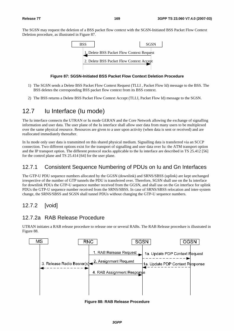
Release 7T 169 3GPP TS 23.060 V7.4.0 (2007-03)
The SGSN may request the deletion of a BSS packet flow context with the SGSN-Initiated BSS Packet Flow Context Deletion procedure, as illustrated in Figure 87.
1. Delete BSS Packet Flow Context Request
2. Delete BSS Packet Flow Context Accept
BSS SGSN
Figure 87: SGSN-Initiated BSS Packet Flow Context Deletion Procedure
1) The SGSN sends a Delete BSS Packet Flow Context Request (TLLI , Packet Flow Id) message to the BSS. The BSS deletes the corresponding BSS packet flow context from its BSS context.
2) The BSS returns a Delete BSS Packet Flow Context Accept (TLLI, Packet Flow Id) message to the SGSN.
12.7 Iu Interface (Iu mode) The Iu interface connects the UTRAN or Iu mode GERAN and the Core Network allowing the exchange of signalling information and user data. The user plane of the Iu interface shall allow user data from many users to be multiplexed over the same physical resource. Resources are given to a user upon activity (when data is sent or received) and are reallocated immediately thereafter.
In Iu mode only user data is transmitted on this shared physical medium. Signalling data is transferred via an SCCP connection. Two different options exist for the transport of signalling and user data over Iu: the ATM transport option and the IP transport option. The different protocol stacks applicable to the Iu interface are described in TS 25.412 [56] for the control plane and TS 25.414 [64] for the user plane.
12.7.1 Consistent Sequence Numbering of PDUs on Iu and Gn Interfaces The GTP-U PDU sequence numbers allocated by the GGSN (downlink) and SRNS/SBSS (uplink) are kept unchanged irrespective of the number of GTP tunnels the PDU is transferred over. Therefore, SGSN shall use on the Iu interface for downlink PDUs the GTP-U sequence number received from the GGSN, and shall use on the Gn interface for uplink PDUs the GTP-U sequence number received from the SRNS/SBSS. In case of SRNS/SBSS relocation and inter-system change, the SRNS/SBSS and SGSN shall tunnel PDUs without changing the GTP-U sequence numbers.
12.7.2 [void]
12.7.2a RAB Release Procedure UTRAN initiates a RAB release procedure to release one or several RABs. The RAB Release procedure is illustrated in Figure 88.
Figure 88: RAB Release Procedure
3GPP

Release 7T 170 3GPP TS 23.060 V7.4.0 (2007-03)
1) UTRAN initiates the procedure by sending a RAB Release Request (For each RAB to be released: RAB ID, Cause) message to the SGSN.
1a) If PDP Contexts associated with the released RABs are to be preserved and Direct Tunnel was established the SGSN sends Update PDP Context Request to the GGSN(s) concerned to establish the GTP tunnel between SGSN and GGSN. The GGSN(s) update the Address for User Plane and TEID for downlink data and return an Update PDP Context Response. The No QoS negotiation indication is set in Update PDP Context Request to indicate to the GGSN that the SGSN does not upgrade the previously negotiated QoS attributes and that the GGSN shall not negotiate the QoS attributes.
2) The SGSN sends a RAB Assignment Request (For each RAB to be released: RAB ID, Cause) to the UTRAN.
3) The Radio Bearer(s) are released if still existing.
4) UTRAN sends a RAB Assignment Response (For each released RAB: RAB ID, GTP SND, GTP SNU) to the SGSN. GTP SND and GTP SNU enable the SGSN to restore the values in case the PDP context is maintained and the RAB is re-established at a later stage.
12.7.3 Iu Release Procedure This procedure is used to release the Iu interface. This procedure also triggers the release of all the Iu connections and changes the 3G-SGSN PMM state to PMM-IDLE. Both RAN-initiated and SGSN-initiated Iu release procedures are shown in Figure 89.
NOTE 1: Message 1 is only sent when the RAN-initiated Iu release procedure is considered. NOTE 2: Message 1 is not sent but message 2 is sent when the SGSN-initiated Iu release procedure is considered.
Figure 89: Iu Release Procedure
1) The RAN notices that the RRC connection has been released or detects a need to release the radio resources. It sends an Iu Release Request (Cause) message to the SGSN. Cause indicates the reason for the release (e.g. O&M Intervention, Unspecified Failure, User Inactivity, Repeated Integrity Checking Failure, or Release due to UE generated signalling connection release). User Inactivity means that the RAN decided to release an MS that shows no more activity, in the case where the MS has only non real-time RABs established, in order to optimise the radio usage after the RRC-Connection-Release timer expired.
1a) If PDP Contexts associated with the released RABs are to be preserved and Direct Tunnel was established the SGSN sends Update PDP Context Request to the GGSN(s) concerned to establish the GTP tunnel between SGSN and GGSN. The No QoS negotiation indication is set in Update PDP Context Request to indicate to the GGSN that the SGSN does not upgrade the previously negotiated QoS attributes and that the GGSN(s) shall not negotiate the QoS attributes. The GGSN(s) update the Address for User Plane and TEID for downlink data and return an Update PDP Context Response.
2) The SGSN releases the Iu by sending the Iu Release Command (Cause) message to the RAN. This message may be triggered either by an Iu Release Request message, or by another SGSN event (e.g., authentication failure or detach). The SGSN shall take the responsibility to release the Iu interface when the UE has no active PDP context, either immediately or after some timeout. It is optional for the SGSN to send the Iu Release Command message after an Iu Release Request message with Cause set to User Inactivity is received from the RAN.
3GPP

Release 7T 171 3GPP TS 23.060 V7.4.0 (2007-03)
3) If the RRC connection is not already released (Cause = User Inactivity), the RAN sends a Release RRC Connection message to the MS.
4) The MS returns a Release RRC Connection Acknowledge message to the RAN.
5) The RAN confirms the Iu release by returning an Iu Release Completion (for each released RAB: RAB ID, GTP SND, GTP SNU) message to the SGSN. GTP SND and GTP SNU enable the SGSN to restore the values in case the PDP context is maintained and the RAB is re-established at a later stage.
If the RNC does not receive the Release RRC Connection Acknowledge message and if Cause is different from Authentication Failure or Detach, it should send a failure message to the SGSN, and the SGSN should stay in the MM-CONNECTED state.
After Iu release, the MS and the SGSN shall modify PDP context(s) that use streaming or conversational traffic class according to the rules in clause "RNC-Initiated PDP Context Modification Procedure".
12.7.4 RAB Assignment Procedure The purpose of the RAB Assignment procedure is to enable establishment of new RABs for a given MS and/or modification and/or release of already established RABs. When this procedure is executed and if there is any PDP context without radio access bearer assigned, the SGSN will decide which RABs to re-establish out of those which do not have maximum bit rates of 0 kbit/s for uplink and downlink. The same messages are used for the three mentioned actions and it is only the content carried by the messages that is different. The RAB Assignment procedure, which is shown below, is specified in TS 25.413 [56b]. The RRC protocol is specified in TS 25.331 [52].
. . .
Figure 90: RAB Assignment Procedure
1) The SGSN sends a RAB Assignment Request message to the RAN to establish, modify, or release one or several RABs. For each requested RAB or modified, if the RAB is allowed for queuing and the resource situation requires it, the RAN may place the RAB in the establishment queue. If Direct Tunnel is used the SGSN provides to the RNC the GGSN's Address(es) for User Plane and TEID(s) for Uplink data.
2) The RAN establishes, modifies, or releases the appropriate radio bearers.
3) The RAN returns a RAB Assignment Response message to the SGSN. If the request to establish or modify one or several RABs has been queued, the RAN will report the outcome of the establishment or modification in subsequent RAB Assignment Response messages. If the SGSN receives a RAB Assignment Response message with a cause indicating that the requested QoS profile(s) can not be provided (e.g. "Requested Maximum Bit Rate not Available"), then the SGSN may send a new RAB Assignment Request message with different QoS profile(s). The number of re-attempts, if any, as well as how the new QoS profile(s) values are determined is implementation dependent.
4) If the SGSN established Direct Tunnel it shall send Update PDP Context Request to the GGSN(s) concerned and include the RNC's Address for User Plane, downlink TEID for data, No QoS negotiation indication and the DTI. DTI is used to instruct the GGSN to apply Direct Tunnel specific error handling as described in clause 13.8, The No QoS negotiation indication is set in Update PDP Context Request to indicate to the GGSN that the SGSN does not upgrade the previously negotiated QoS attributes and that the GGSN(s) shall not negotiate the QoS attributes. The GGSN(s) update the Address for User Plane and TEID for downlink data and return an Update PDP Context Response.
3GPP

Release 7T 172 3GPP TS 23.060 V7.4.0 (2007-03)
12.7.5 Location Reporting Procedure This procedure is used by an SGSN to request the RAN to report where the MS is currently located, or to report when the MS moves into or out of a given service area. This procedure relates to location services (LCS) and other services (e.g. CAMEL and emergency calls) in Iu mode. The overall LCS procedure is described in the LCS stage-2 specification, see TS 23.271 [65].
SGSNMS
1. Location reporting control
3. Location Report
RAN
2. UE enter a newservice location
4. Cancel location reporting
Figure 91: Location Reporting Procedure
1) The SGSN detects from the subscriber data the need to monitor in which service area an MS in the PMM-CONNECTED state with an Iu interface connection is located. The SGSN sends a Location Reporting Control (Service Area Code(s), Reporting Type) message to the RAN. The RAN stores the Service Area Code(s) as reporting area(s) for this MS. For example, a service area may be a location area with restricted access. Reporting Type indicates whether the message is intended to start a reporting period or trigger a stand-alone report about the current location of the MS.
2) The RAN detects that the MS moves into or out of a reporting area. Alternatively, the RAN derives the current location of the MS if this was requested by the SGSN.
3) The RAN sends a Location Report message informing the SGSN about where the MS is located. When the SGSN has requested the current location of the MS, the RAN shall include the requested location information , i.e. the Service Area Indication, in the Location Report message, if the RAN cannot determine current Service Area of the mobile, it indicates that the request could not be fulfilled, and may report Last Known Service Area with an indication of how long has past since the mobile was known to be in the indicated Service Area. The SGSN may then perform specific actions.
4) The SGSN can send a Cancel Location Reporting message to inform the RAN that it should terminate location reporting for a given MS. This message is needed only when the reporting was requested for a reporting period.
The procedure is implicitly cancelled at SRNC/SBSC relocation. If the service is still required in the new SRNC/SBSC or new SGSN, a new Location Reporting Control message shall be sent.
12.8 Abis Interface (A/Gb mode) When the MAC and RLC layer functions are positioned remote to the BTS, the information between the Channel Codec Unit (CCU) and the remote Packet Control Unit (PCU) is transferred in frames with a fixed length of 320 bits (20 ms). In the present document these frames are denoted "PCU Frames" and are an extension to the "TRAU frames" defined in TS 48.060 [22]. Within these frames both GPRS data and the RLC/MAC associated control signals are transferred.
The Abis interface should be the same if the PCU is positioned at the BSC site (option B in Figure 92) or at the SGSN site (option C in Figure 92). In option B, the PCU could be implemented as an adjunct unit to the BSC. In option C, the BSC should be considered as transparent for 16 kbit/s channels. In configurations B and C the PCU is referred to as being a remote PCU.
The remote PCU is considered a part of the BSC, and using BSC internal signals may provide the signalling between the BSC and the PCU. The inband signalling between the CCU and the PCU functions, using PCU frames is required when the Abis interface is applied (options B and C in Figure 92).
3GPP

Release 7T 173 3GPP TS 23.060 V7.4.0 (2007-03)
Abis
BTS BSC site GSN site
BSC site GSN site
BSC site GSN site
CCU
PCUCCU
BTSCCU
CCU
BTSCCU
CCU
Um Gb
A
B
C
PCU
PCU
Key: Circuit-switching function (16 or 64 kbit/s)
Packet-switching function
Gb
Figure 92: Remote Packet Control Unit (PCU) Positions
The PCU is responsible for the following MAC and RLC layer functions as defined in TS 43.064 [11]:
- LLC layer PDU segmentation into RLC blocks for downlink transmission;
- LLC layer PDU reassembly from RLC blocks for uplink transmissions;
- PDCH scheduling functions for the uplink and downlink data transfers;
- PDCH uplink ARQ functions, including RLC block ack / nak;
- PDCH downlink ARQ function, including buffering and retransmission of RLC blocks;
- channel access control functions, e.g. access requests and grants; and
- radio channel management functions, e.g. power control, congestion control, broadcast control information, etc.
The functions inside the Channel Codec Unit (CCU) are:
- the channel coding functions, including FEC and interleaving;
- radio channel measurement functions, including received quality level, received signal level and information related to timing advance measurements; and
- for EGPRS, in case of incremental redundancy mode of operation, enhanced channel coding functions.
The BSS is responsible for allocation and de-allocation of radio resources. A PCU frame shall be transferred between the PCU and the CCU every 20 ms.
12.8.1 Remote Packet Control Unit When the Packet Control Unit (PCU) is remote to the BTS, the Channel Codec Unit (CCU) in the BTS may control some of the functions in the remote PCU in the BSC. As well, the PCU may control some of the functions of the CCU. Inband signalling provides the remote control by using the control bits (C-bits) in each PCU frame.
3GPP

Release 7T 174 3GPP TS 23.060 V7.4.0 (2007-03)
12.9 Gn Interface (A/Gb mode) During the PS handover procedure the PS Handover Request Context containing packet flow specific information needs to be transferred between SGSNs. The detailed description of the procedures used during PS handover from GERAN A/Gb mode to GERAN A/Gb mode or GERAN A/Gb mode to Iu mode and vice-versa are described in TS 29.060 [26].
13 Information Storage This clause describes information storage structures required for GPRS, and the recovery and restoration procedures needed to maintain service if inconsistencies in databases and lost or invalid database information occur.
13.1 HLR IMSI is the prime key to the subscription data stored in the HLR. There may be several sets of GPRS subscription data per IMSI. This is illustrated in Figure 93.
IMSI
Password CS GPRS Suppl. Services
BS1 BS3BS2
SS1Status
SS1Status
SS1Status
PDP1 PDP3PDP2 SS2Prov.
SS1Prov.
Supplementary Service 2Activation Status
Basic Services
Figure 93: Subscription Data
As Figure 93 indicates, the GPRS subscription data is at the same level as basic services. Each PDP subscription is seen as a basic service. Supplementary services are provisioned as part of the overall subscription. Activation of SSs is either at the basic service level (SS1) or at the overall subscription level (SS2).
Table 5 shows the GPRS subscription data contained in the HLR.
3GPP

Release 7T 175 3GPP TS 23.060 V7.4.0 (2007-03)
Table 5: HLR GPRS Subscription Data
Field Description IMSI IMSI is the main reference key. MSISDN The basic MSISDN of the MS. SGSN Number The SS7 number of the SGSN currently serving this MS. SGSN Address The IP address of the SGSN currently serving this MS. Subscribed Charging Characteristics
The charging characteristics for the MS, e.g. normal, prepaid, flat-rate, and/or hot billing subscription.
Trace Reference Identifies a record or a collection of records for a particular trace. Trace Type Indicates the type of trace, e.g. MSC/BSS trace, HLR trace, and/or
SGSN/GGSN/BSS trace. OMC Identity Identifies the OMC that shall receive the trace record(s). SMS Parameters SMS-related parameters, e.g. operator-determined barring. MS PS Purged for GPRS Indicates that the MM and PDP contexts of the MS are deleted
from the SGSN. MNRG Indicates that the MS is not reachable through an SGSN, and that
the MS is marked as not reachable at the SGSN and possibly at the GGSN.
GGSN-list The GSN number and optional IP address pair related to the GGSN that shall be contacted when activity from the MS is detected and MNRG is set. The GSN number shall be either the number of the GGSN or the protocol-converting GSN as described in the clauses "MAP-based GGSN - HLR Signalling" and "GTP and MAP-based GGSN - HLR Signalling".
GPRS-CSI Optional GPRS CAMEL subscription information, see TS 23.016 [5b]
MG-CSI Optional Mobility Management for GPRS CAMEL subscription information, see TS 23.016 [5b].
PDP Context Identifier Index of the PDP context. PDP Type PDP type, e.g. PPP or IP. PDP Address PDP address, e.g., an IP address. This field shall be empty if
dynamic addressing is allowed. Access Point Name A label according to DNS naming conventions describing the
access point to the packet data network. QoS Profile Subscribed The quality of service profile subscribed. QoS Profile Subscribed
is the default level if a particular QoS profile is not requested. . QoS Profile Subscribed is also the maximum QoS per PDP context to the associated APN.
VPLMN Address Allowed Specifies whether the MS is allowed to use the APN in the domain of the HPLMN only, or additionally the APN in the domain of the VPLMN.
PDP context Charging Characteristics
The charging characteristics of this PDP context, e.g. normal, prepaid, flat-rate, and/or hot billing.
ODB for PS parameters Indicates that the status of the operator determined barring for packet oriented services.
Access Restriction Indicates the access restriction subscription information. (Note, the access restriction applies to both packet and circuit oriented services).
IMEI International Mobile Equipment Identity SVN Software Version Number
NOTE: IMEI and SVN are stored in HLR when the Automatic Device Detection feature is supported, see subclause 15.5.
13.2 SGSN SGSN maintains MM context and PDP context information for MSs in the STANDBY, READY, PMM-IDLE, and PMM-CONNECTED states. Table 6 shows the context fields for one MS.
During the Intersystem Change, when new Authentication and Key Agreement is not performed, the KSI in the new 3G-SGSN shall be assigned the value of the CKSN, which has been sent by the MS. Similarly, in the new 2G-SGSN, when AKA does not take place, the CKSN shall be assigned the value of the KSI, which has been sent by the MS.
3GPP

Release 7T 176 3GPP TS 23.060 V7.4.0 (2007-03)
Table 6: SGSN MM and PDP Contexts
Field Description A/Gb mode
Iu mode
IMSI IMSI is the main reference key. X X MM State Mobility management state, IDLE, STANDBY, READY,
PMM-DETACHED, PMM-IDLE, or PMM-CONNECTED. X X
P-TMSI Packet Temporary Mobile Subscriber Identity. X X P-TMSI Signature A signature used for identification checking purposes. X X IMEI International Mobile Equipment Identity X X SVN Software Version Number (stored by SGSNs supporting the
"Provision of UE Specific Behaviour Information to Network Entities" feature as defined in TS 23.195 [76].) or the "Automatic Device Detection" feature, see subclause 15.5.
3) X
MSISDN The basic MSISDN of the MS. X X Routeing Area Current routeing area. X X Cell Identity Current cell in READY state, last known cell in STANDBY or IDLE
state. X
Cell Identity Age Time elapsed since the last LLC PDU was received from the MS at the SGSN.
X
Service Area Code Last known SAC when initial UE message was received or Location Reporting procedure was executed.
X
Service Area Code Age Time elapsed since the last SAC was received at the 3G-SGSN. X VLR Number The VLR number of the MSC/VLR currently serving this MS. X X New SGSN Address The IP address of the new SGSN where buffered and not sent
N-PDUs should be forwarded to. X X
Authentication Vectors Authentication and ciphering parameters (authentication triplets or quintets)..
X X
Kc Currently used A/Gb mode ciphering key. X 2) CKSN Ciphering key sequence number of Kc. X 2) Ciphering algorithm Selected ciphering algorithm. X X CK Currently used Iu mode ciphering key. 1) X IK Currently used Iu mode integrity key. 1) X KSI Key Set Identifier. 1) X MS Radio Access Capability MS radio access capabilities. X MS Network Capability MS network capabilities. X X DRX Parameters Discontinuous reception parameters. X X MNRG Indicates whether activity from the MS shall be reported to the
HLR. X X
NGAF Indicates whether activity from the MS shall be reported to the MSC/VLR.
X X
PPF Indicates whether paging for PS and CS services can be initiated. X X Subscribed Charging Characteristics
The charging characteristics for the MS, e.g. normal, prepaid, flat-rate, and/or hot billing subscription.
X X
Selected CN operator id Selected core network operator idenity (to support network sharing as defined in TS 23.251 [83]).
4)
Trace Reference Identifies a record or a collection of records for a particular trace. X X Trace Type Indicates the type of trace. X X Trigger Id Identifies the entity that initiated the trace. X X OMC Identity Identifies the OMC that shall receive the trace record(s). X X SMS Parameters SMS-related parameters, e.g. operator-determined barring. X X Recovery Indicates if HLR or VLR is performing database recovery. X X Radio Priority SMS The RLC/MAC radio priority level for uplink SMS transmission. X Access Restriction The access restriction subscription information. X X GPRS-CSI Optional GPRS CAMEL subscription information, see
TS 23.016 [5b] X X
MG-CSI Optional Mobility Management for GPRS CAMEL subscription information, see TS 23.016 [5b].
X X
ODB for PS parameters Indicates that the status of the operator determined barring for packet oriented services.
X X
Each MM context contains zero or more of the following PDP contexts: PDP Context Identifier Index of the PDP context. X X PDP State Packet data protocol state, INACTIVE or ACTIVE. X X PDP Type PDP type, e.g. PPP or IP. X X PDP Address PDP address, e.g. an IP address. X X APN Subscribed The APN received from the HLR. X X APN in Use The APN currently used. This APN shall be composed of the APN
Network Identifier and the APN Operator Identifier. X X
3GPP

Release 7T 177 3GPP TS 23.060 V7.4.0 (2007-03)
Field Description A/Gb mode
Iu mode
NSAPI Network layer Service Access Point Identifier. X X TI Transaction Identifier. X X TEID for Gn/Gp Tunnel Endpoint Identifier for the Gn and Gp interfaces. X X TEID for Iu Tunnel Endpoint Identifier for the Iu interface. X GGSN Address in Use The IP address of the GGSN currently used. X X VPLMN Address Allowed Specifies whether the MS is allowed to use the APN in the domain
of the HPLMN only, or additionally the APN in the domain of the VPLMN.
X X
QoS Profile Subscribed The quality of service profile subscribed. X X QoS Profile Requested The quality of service profile requested. X X QoS Profile Negotiated The quality of service profile negotiated. X X Radio Priority The RLC/MAC radio priority level for uplink user data
transmission. X
Packet Flow Id Packet flow identifier. X Aggregate BSS QoS Profile Negotiated
The aggregate BSS quality of service profile negotiated for the packet flow that this PDP context belongs to.
X
Send N-PDU Number SNDCP sequence number of the next downlink N-PDU to be sent to the MS.
X
Receive N-PDU Number SNDCP sequence number of the next uplink N-PDU expected from the MS.
X
GTP-SND GTP-U sequence number of the next downlink N-PDU to be sent to the MS.
X X
GTP-SNU GTP-U sequence number of the next uplink N-PDU to be sent to the GGSN.
X X
PDCP-SND Sequence number of the next downlink in-sequence PDCP-PDU to be sent to the MS.
X
PDCP-SNU Sequence number of the next uplink in-sequence PDCP-PDU expected from the MS.
X
Charging Id Charging identifier, identifies charging records generated by SGSN and GGSN.
X X
PDP Context Charging Characteristics
The charging characteristics of this PDP context, e.g. normal, prepaid, flat-rate, and/or hot billing.
X X
RNC Address in Use The IP address of the RNC/BSC currently used. X Prohibit Payload Compression
Indicates that the SGSN should negotiate no data compression for this PDP context.
X
APN Restriction Denotes the restriction on the combination of types of APN for the APN associated with this PDP Context. (See Note)
X X
DTI Indicates whether SGSN has established direct user plane tunnel between RNC and GGSN for this PDP context.
X
CGI/SAI/RAI Change Report Required
Denotes the need to send changes in CGI/SAI or RAI to the GGSN associated with this PDP Context. (See Note)
BCM The negotiated BCM. X X NOTE: APN Restriction and CGI/SAI/RAI Change Report Required shall not be transferred between SGSNs during
mobility management. The information marked with a "1)" in table 6 may be maintained if authentication is performed by the UMTS authentication procedure.
The information marked with a "2)" in table 6 may be maintained if authentication is performed by the GSM authentication procedure.
The information marked with a "3)" in table 6 is optional. It can be sent to a new SGSN at RA update.
The information marked with a "4)" in table 6 is used in networks that support network sharing as defined in TS 23.251 [83].
3GPP

Release 7T 178 3GPP TS 23.060 V7.4.0 (2007-03)
13.3 GGSN GGSN maintains activated PDP contexts. Table 7 shows the PDP context fields for one PDP Address.
Table 7: GGSN PDP Context
Field Description IMSI International Mobile Subscriber Identity. NSAPI Network layer Service Access Point Identifier. MSISDN The basic MSISDN of the MS. PDP Type PDP type; e.g. PPP or IP. PDP Address PDP address; e.g. an IP address. Dynamic Address Indicates whether PDP Address is static or dynamic. APN in Use The APN Network Identifier currently used. TEID Tunnel Endpoint Identifier. TFT Traffic flow template. QoS Profile Negotiated The quality of service profile negotiated. SGSN Address The IP address of the SGSN currently serving this MS. MNRG Indicates whether the MS is marked as not reachable for PS at the
HLR. Recovery Indicates if the SGSN is performing database recovery. GTP-SND GTP-U sequence number of the next downlink N-PDU to be sent to
the SGSN. GTP-SNU GTP-U sequence number of the next uplink N-PDU to be received
from the SGSN. Charging Id Charging identifier, identifies charging records generated by SGSN
and GGSN. Charging Characteristics The charging characteristics for this PDP context, e.g. normal,
prepaid, flat-rate, and/or hot billing. Trace Reference Identifies a record or a collection of records for a particular trace. Trace Type Indicates the type of trace. Trigger Id Identifies the entity that initiated the trace. OMC Identity Identifies the OMC that shall receive the trace record(s). Prohibit Payload Compression
Indicates that the SGSN should negotiate no data compression for this PDP context.
SGSN support for CGI/SAI/RAI change reporting
Indicated that the SGSN serving the MS supports procedures for reporting CGI/SAI/RAI changes according to clause 15.1.1a.
CGI/SAI/RAI Change Report Required
Denotes whether the SGSN is requested to send changes in CGI/SAI or RAI to the GGSN associated with this PDP Context.
BCM The negotiated Bearer Control Mode. DTI Indicates whether SGSN has established direct user plane tunnel
between RNC and GGSN for this PDP Context.
3GPP

Release 7T 179 3GPP TS 23.060 V7.4.0 (2007-03)
If a PDP context is enabled for network-requested PDP context activation, then IMSI, PDP Type, PDP Address, SGSN Address and MNRG contain valid information also when the PDP context is inactive and when the MS is GPRS-detached.
13.4 MS Each MS supporting GPRS maintains MM and PDP context information in IDLE, STANDBY, READY, PMM-DETACHED, PMM-IDLE, and PMM-CONNECTED states. The information may be contained in the MS and the TE. Table 8 shows the MS context fields.
Table 8: MS MM and PDP Contexts
Field SIM Description A/Gb mode
Iu mode
IMSI G, U International Mobile Subscriber Identity. X X MM State Mobility management state, IDLE, STANDBY, READY,
PMM-DETACHED, PMM-IDLE, or PMM-CONNECTED. X X
P-TMSI G, U Packet Temporary Mobile Subscriber Identity. X X P-TMSI Signature G, U A signature used for identification checking purposes. X X Routeing Area G, U Current routeing area. X X Cell Identity Current cell. X Kc G Current A/Gb mode ciphering key. X 2) KSI / CKSN G, U Key Set Identifier for IK Next, CK Next / key sequence number of
Kc. X X
Ciphering algorithm Selected ciphering algorithm. X X CK Currently used Iu mode ciphering key. 1) X CK Next U Iu mode ciphering key to be used after the next security mode
command. 1) X
IK Currently used Iu mode integrity key. 1) X IK Next U Integrity key to be used after the next security mode command. 1) X MS Radio Access Capability
MS radio access capabilities. X X
UE Capability UE radio capabilities. X MS Network Capability
MS network capabilities. X X
DRX Parameters Discontinuous reception parameters. X X Radio Priority SMS The RLC/MAC radio priority level for uplink SMS transmission. X Each MM context contains zero or more of the following PDP contexts: PDP Type PDP type, e.g. PPP or IP. X X PDP Address PDP address; e.g. an IP address. X X PDP State Packet data protocol state, INACTIVE or ACTIVE. X X Dynamic Address Allowed Specifies whether the MS is allowed to use a dynamic address. X X APN Requested The APN requested. X X NSAPI Network layer Service Access Point Identifier. X X TI Transaction Identifier. X X QoS Profile Requested The quality of service profile requested. X X QoS Profile Negotiated The quality of service profile negotiated. X X TFT Traffic flow template. X X Radio Priority The RLC/MAC radio priority level for uplink user data
transmission. X
Packet Flow Id Packet flow identifier. X Send N-PDU Number SNDCP sequence number of the next uplink N-PDU to be sent to
the SGSN. X X
Receive N-PDU Number SNDCP sequence number of the next downlink N-PDU expected from the SGSN.
X X
PDCP-SND Sequence number of the next downlink in-sequence PDCP-PDU expected from the RNC.
X
PDCP-SNU Sequence number of the next uplink in-sequence PDCP-PDU to be sent to the RNC.
X
BCM The negotiated Bearer Control Mode X X
The information marked with a "1)" in table 8 may be maintained if authentication is performed by the UMTS authentication procedure.
3GPP

Release 7T 180 3GPP TS 23.060 V7.4.0 (2007-03)
The information marked with a "2)" in table 8 may be maintained if authentication is performed by the GSM authentication procedure.
The information marked with a "U" in table 8 shall be stored in the USIM.
The information marked with a "G" in table 8:
- shall be stored in the GSIM if the connected SIM is GPRS-aware; and
- may be stored in the ME after GPRS detach if the connected GSIM is not GPRS-aware.
If the GSIM is GPRS service-aware, then the IMSI, P-TMSI, P-TMSI Signature, Routeing Area, Kc, and CKSN stored in the GSIM shall be used for GPRS services.
If the GSIM is not GPRS service-aware, the P-TMSI, P-TMSI Signature, Routeing Area, Kc, and CKSN stored in the ME shall be used if and only if the IMSI stored in the GSIM is identical to the IMSI image maintained in the ME. If the IMSI stored in the GSIM is different from the IMSI image in the ME, the IMSI image in the ME shall not be used, and the MS shall identify itself with the IMSI stored in the SIM when performing a GPRS attach. IMSI, P-TMSI, P-TMSI Signature, Routeing Area, Kc, and CKSN may be stored in the ME after the GPRS attach has been successfully performed.
When using a USIM, the IMSI, P-TMSI, P-TMSI Signature, Routeing Area, Kc, CK Next, IK Next, and CKSN / KSI stored in the USIM, and the CK and IK stored in the ME, shall be used for GPRS services.
13.5 MSC/VLR The MSC/VLR may store the SGSN number of GPRS-attached MSs that are also IMSI-attached. Table 9 shows the MSC/VLR association for one MS.
Table 9: MSC/VLR Association
Field Description IMSI IMSI is the main reference key. SGSN Number The SGSN number of the SGSN currently serving this MS.
13.6 BSS in A/Gb mode Table 10 shows the BSS context fields for one MS.
Table 10: BSS Context
Field Description IMSI IMSI is the main reference key. TLLI Temporary Logical Link Identity. Trace Reference Identifies a record or a collection of records for a particular trace. Trace Type Indicates the type of trace. Trigger Id Identifies the entity that initiated the trace. OMC Identity Identifies the OMC that shall receive the trace record(s). Each BSS context contains one or more BSS Packet Flow contexts: Packet Flow Id Packet flow identifier. Aggregate BSS QoS Profile Negotiated
The aggregate BSS quality of service profile negotiated for this packet flow.
BSS Packet Flow Timer BSS packet flow context inactivity timer.
13.7 RNC/BSC for Iu mode RNC/BSC maintains RNC/BSC Context for CN-related information in PMM-CONNECTED state. RNC/BSC also contains RAB contexts for activated RABs. Table 11 shows the context fields for one MS.
3GPP

Release 7T 181 3GPP TS 23.060 V7.4.0 (2007-03)
Table 11: RNC/BSC Context
Field Description IMSI IMSI is the main reference key. UE Capability UE radio capabilities. UESBI-Iu Stored by an RNC which supports the "Provision of UE Specific Behaviour Information
to Network Entities" feature defined in TS 23.195 [76]. UESBI-Uu Stored by an RNC which supports the "Provision of UE Specific Behaviour Information
to Network Entities" feature defined in TS 23.195 [76]. SAI Current or last known SAI SAI age Time elapsed since the RNC last established the UE's last known SAI Trace Reference Identifies a record or a collection of records for a particular trace. Trace Type Indicates the type of trace. Trigger Id Identifies the entity that initiated the trace. OMC Identity Identifies the OMC that shall receive the trace record(s). Each RNC context contains zero or more RNC RAB contexts: RAB ID Radio Access Bearer Identifier. PDP Type PDP type, e.g. PPP or IP. TEID Tunnel Endpoint Identifier. GGSN Address in Use The IP address of the SGSN currently used. QoS Profile Negotiated The quality of service profile negotiated for this RAB. GTP-SND GTP-U sequence number of the next downlink in-sequence N-PDU to be sent to the
MS. GTP-SNU GTP-U sequence number of the next uplink in-sequence N-PDU to be sent to the
GGSN. PDCP-SND Sequence number of the next downlink in-sequence PDCP-PDU to be sent to the MS.PDCP-SNU Sequence Number of the next uplink in-sequence PDCP-PDU expected from the MS.
13.8 Recovery and Restoration Procedures The recovery and restoration procedures are intended to maintain service if inconsistencies in databases occur and at lost or invalid database information. "Invalid" in this context means that the database entry cannot be regarded as reliable.
13.8.1 HLR Failure When an HLR restarts, it sends to each SGSN where one or more of its MSs are registered a Reset message. This causes the SGSN to mark the relevant MM contexts as invalid, and to set NGAF if an SGSN – MSC/VLR association exists. After receipt of the first valid LLC frame (for A/Gb mode) or after receipt of the first valid GTP-U packet or uplink signalling message (for Iu mode) from a marked MS, the SGSN performs an update location to the HLR as in the attach or inter-SGSN RA update procedures, and, if NGAF is set, the procedure in clause "Non-GPRS Alert" is followed. The update location procedure and the procedure towards the MSC/VLR may be delayed by the SGSN for a maximum operator configuration-depending on the utilisation of resources during given time period to avoid high signalling load. The periodic backup of HLR data to non-volatile storage is mandatory as described in TS 23.007 [5].
13.8.2 SGSN Failure When an SGSN fails, it deletes all MM and PDP contexts affected by the failure. SGSN storage of subscriber data is volatile. Based on configuration data, the SGSN shall send a Reset message to each of its associated VLRs. The VLR shall mark all associations containing the restarted SGSN as unreliable. See TS 23.007 [5]. In the case of optional CAMEL interaction the failing SGSN shall invoke the CAMEL-GPRS-Exception procedure towards the GSM-SCFs.
If data or signalling, except GPRS attach and RA update, is received in an SGSN from an MS for which no MM context exists in the SGSN, the SGSN shall discard the data or signalling.
If an RA update request is received in an SGSN from an MS for which no MM context exists in the SGSN, or in the old SGSN for the inter-SGSN RA update case, the SGSN shall reject the RA update with an appropriate cause. In order to remain GPRS-attached, the MS shall then perform a new GPRS attach and should (re-)activate PDP contexts.
3GPP

Release 7T 182 3GPP TS 23.060 V7.4.0 (2007-03)
If a service request is received in a 3G-SGSN from an MS for which no MM context exists in the 3G-SGSN, the 3G-SGSN shall reject the service request with an appropriate cause. In order to remain GPRS-attached, the MS shall then perform a new GPRS attach and should (re-) activate PDP contexts.
NOTE: In some cases, user interaction may be required, and then the MS cannot (re-)activate the PDP contexts automatically.
When the SGSN receives a PDU Notification Request message for which no MM context exists, the SGSN returns a PDU Notification Response message to the GGSN with an appropriate cause (see clause "Unsuccessful Network-Requested PDP Context Activation Procedure"), and the SGSN may search the MS by paging with the IMSI in the SGSN area. An MS that is paged for PS services with IMSI as the identifier shall perform a new GPRS attach and should (re-)activate PDP contexts.
When the SGSN receives a GTP-U PDU from the GGSN for which no PDP context exists, it shall discard the GTP-U PDU and send a GTP error indication to the originating GGSN. The GGSN shall mark the related PDP context as invalid.
When the SGSN receives a GTP-U PDU from the RNC for which no PDP context exists, the SGSN shall discard the GTP-U PDU and send a GTP error indication to the originating RNC. The RNC shall initiate the RAB Release procedure with the error cause 'GTP Resources Unavailable' and shall immediately locally release the RAB (i.e. without waiting for a response from the SGSN).
When the SGSN receives a mobile-terminated SM from the SMS-GMSC for an IMSI unknown in the SGSN, it rejects the request.
When the SGSN receives a paging request over the Gs interface for an IMSI unknown in the SGSN and the SGSN has not completed recovery, the SGSN may page the MS for packet services with IMSI as identifier in the area specified by the location information provided by the MSC/VLR. If no such location information is provided, the SGSN may page the MS in the routeing areas corresponding to that MSC/VLR. After the MS performs a combined GPRS attach, the SGSN may continue serving the Gs interface paging request.
13.8.3 GGSN Failure When a GGSN fails, all its PDP contexts affected by the failure become invalid and may be deleted. GGSN storage of subscriber data is volatile.
When the GGSN receives a GTP-U PDU for which no PDP context exists, it shall discard the GTP-U PDU and return a a GTP error indication to the originating node (the SGSN or, if Direct Tunnel is established, the RNC).
If the RNC receives a GTP error indication, it shall initiate the RAB Release procedure with the error cause 'GTP Resources Unavailable' and immediately locally release the RAB (i.e. without waiting for a response from the SGSN).
If the SGSN receives a GTP error indication from a GGSN or a RAB Release Request from the RNC with the error cause 'GTP Resources Unavailable' (indicating that the PDP context does not exist on GGSN) it shall mark the related PDP context as invalid and send a Deactivate PDP Context Request message to the MS with cause 're-activation required'.
The GGSN should ensure as far as possible that previously used TEID values are not immediately reused after a GGSN restart, in order to avoid inconsistent TEID allocation throughout the network.
13.8.4 VLR Failure When a VLR fails, all its associations with SGSNs affected by the failure become invalid and may be deleted. Based on configuration data, the MSC/VLR sends a BSSAP+ Reset message to each of its associated SGSNs. The SGSNs mark all associations containing the restarted VLR as invalid. After receipt of the first valid LLC frame (for A/Gb mode) or after receipt of the first valid GTP-U packet or uplink signalling message (for Iu mode) from an MS that is both GPRS-attached and IMSI-attached, the SGSN shall return a Detach Request (Detach Type) message in order to request the MS to perform a combined RA / LA update. Detach Type shall be set to IMSI Detach. The detach procedure may be delayed by the SGSN for a maximum operator-configuration depending on resource utilisation during given time period to avoid high signalling load.
3GPP

Release 7T 183 3GPP TS 23.060 V7.4.0 (2007-03)
13.8.5 BSS Failure (A/Gb mode) When a BSS fails, all its BSS contexts affected by the failure become invalid and shall be deleted. BSS storage of data is volatile.
13.8.6 RNC/BSC Failure (Iu mode) When an RNC/BSC fails, all its RNC/BSC contexts affected by the failure become invalid and shall be deleted. RNC/BSC storage of data is volatile. An SGSN that recognises unavailability of an RNC/BSC or receives a Reset from an RNC/BSC, shall locally release the RABs for all affected PDP contexts. Any affected PDP contexts that use Direct Tunnel and have an invalid tunnel in GGSN will be recovered when the SGSN receives an Iu connection establishment request from the MS as specified in clause 6.1.2.4.1 or when the GGSN informed the SGSN that the GGSN has received a GTP error indication from RNC.
When the RNC/BSC receives a GTP-U PDU for which no RAB context exists, the RNC/BSC shall discard the GTP-U PDU and return a GTP error indication to the originating node that may be SGSN or GGSN if Direct Tunnel is established.
If the SGSN receives a GTP error indication from the RNC it shall locally release the RAB. The SGSN should preserve the associated PDP context. The SGSN may initiate the RAB Assignment procedure in order to re-establish the RAB.
If the GGSN receives a GTP error indication for a PDP context that has the DTI flag set (i.e. from an RNC), the GGSN should not delete the associated PDP context but mark it as invalid. Any subsequent packets arriving for an invalid PDP context should be discarded. The GGSN shall inform the SGSN that the GGSN received a GTP error indication from RNC. The SGSN shall re-establish the tunnel between the SGSN and GGSN as specified in TS 29.060 [26], which sets the related PDP context as valid again in the GGSN. The GGSN then forwards any subsequent downlink packets to the SGSN.
The RNC should ensure as far as possible that previously used TEID values are not immediately reused after an RNC restart, in order to avoid inconsistent TEID allocation throughout the network.
14 Identities
14.1 IMSI A unique International Mobile Subscriber Identity (IMSI) shall be allocated to each packet-domain subscriber. This is also the case for GPRS-only subscribers. IMSI is defined in TS 23.003 [4].
14.2 Packet TMSI A Packet Temporary Mobile Subscriber Identity shall be allocated to each GPRS-attached MS. P-TMSI is defined in TS 23.003 [4].
14.3 NSAPI and TLLI for A/Gb mode The Network layer Service Access Point Identifier (NSAPI) and Temporary Logical Link Identity (TLLI) are used for network layer routeing. An NSAPI / TLLI pair is unambiguous within a routeing area.
In the MS, NSAPI identifies the PDP-SAP. In the SGSN and GGSN, NSAPI identifies the PDP context associated with a PDP address. Between the MS and the SGSN, TLLI unambiguously identifies the logical link.
When the MS requests the activation of a PDP context, the MS selects one of its unused NSAPIs.
For example (shown figuratively below), the MS receives an IP packet from a connected TE at the IP address A SAP. The IP PDU is encapsulated and NSAPI is initialised to NSAPI-1. TLLI is set to the MS's TLLI before the encapsulated IP packet is passed to the SNDC function. After the IP PDU is received, the SGSN analyses TLLI and NSAPI-1 and determines that the IP PDU shall be sent to the GGSN associated with IP address A.
3GPP

Release 7T 184 3GPP TS 23.060 V7.4.0 (2007-03)
GGSN associated with:IP address A
TLLI
IP address A SAP
IP address B SAP
NSAPI-1
NSAPI-2
Gi
GGSN associated with:IP address B
Gi
GPRS MS
SGSN
IP
IP
Figure 94: Use of NSAPI and TLLI
Within a routeing area, there is a one-to-one correspondence between TLLI and IMSI that is only known in the MS and SGSN. If it is not clear from the context which routeing area a TLLI belongs to, then TLLI is used together with RAI. TLLI is derived from a P-TMSI, and does then provide user identity confidentiality as described in clause "User Identity Confidentiality (A/Gb mode)".
The TLLI address range is divided into four ranges: Local, Foreign, Random, and Auxiliary. The TLLI structure allows the MS and SGSN to deduce the range that a TLLI belongs to. A Local TLLI is derived from the P-TMSI allocated by the SGSN, and is valid only in the RA associated with the P-TMSI. A Foreign TLLI is derived from a P-TMSI allocated in another RA. A Random TLLI is selected randomly by the MS, and is used when the MS does not have a valid P-TMSI available. An Auxiliary TLLI is selected by the SGSN, but is not used in this release of the specifications.
If the MS has a valid P-TMSI associated with the RA where the MS is currently located, the MS shall use a Local TLLI derived from its P-TMSI, unless the MS performs a GPRS attach.
If the MS does not have a valid P-TMSI associated with the current RA, or if the MS performs a GPRS attach, it shall derive a Foreign TLLI from its P-TMSI, or allocate a Random TLLI if no valid P-TMSI is available.
When a TLLI is exchanged between the MS and an SGSN, the TLLI is transmitted at the RLC/MAC layer within the Um protocol stack, and at the BSSGP layer within the Gb protocol stack. NSAPI is transmitted within the SNDCP layer in the user plane, and within the GMM/SM layer in the control plane. In some SM signalling messages, transaction identifier (TI) represents NSAPI . The TI is dynamically allocated by the MS for MS-requested PDP context activation, and by the network for network-requested PDP context activation. The TI is deallocated when a PDP context has been deactivated. TI usage is defined in TS 24.007 [5] and TS 24.008 [13].
By default, unless explicitly specified in the procedures, the TLLI transmitted at the RLC/MAC and BSSGP layers shall be used to identify the MS.
14.4 NSAPI, RB Identity, and RAB ID for Iu mode The Network layer Service Access Point Identifier (NSAPI) and IMSI are used for network layer routeing. An NSAPI / IMSI pair is used to assign a Tunnel Endpoint Identifier (TEID).
In the MS, NSAPI identifies the PDP-SAP. In the SGSN and GGSN, NSAPI identifies the PDP context associated with an MM context.
In the context of this specification, the term RNC refer also to a GERAN BSC when serving an MS in Iu mode.
In communication with the RNC across the Iu-PS and Uu interfaces, the RAB ID is used to identify the radio access bearer and that information element shall be set identical to the NSAPI value. In the RNC, RAB ID identifies the RAB context. Radio Bearer Identity (RB Identity) is used to identify the Uu interface radio bearer(s) associated with the radio access bearer. The RAB ID shall uniquely identify the RAB for a specific CN domain and a particular MS.
There is a one-to-one relationship between NSAPI, Radio Access Bearer, and PDP context. In the packet domain, there is also a one-to-one relationship with Radio Bearer Identity.
3GPP

Release 7T 185 3GPP TS 23.060 V7.4.0 (2007-03)
GGSN associated with:IP address A
IP address B SAP
Gi
GGSN associated with:IP address B
Gi
UMTS MS
RAB ID-1
IP
NSAPI-2
RB Identity
RB Identity RB Identity
RB Identity
RAB ID-2 RAB ID-2
RNC 3G-SGSN
Access Stratum
NSAPI-1NSAPI-1
IP address A SAP
NSAPI-1
NSAPI-2 NSAPI-2
RAB ID-1 RAB ID-1
RAB ID-2RAB ID-2
IP
Figure 95: Use of NSAPI, RB Identity, and RAB ID
When the MS initiates activation of a PDP context, the MS selects one of its unused NSAPIs. When the SGSN initiates a RAB assignment procedure, the SGSN shall include the NSAPI(s) in the RAB ID information element(s).
14.5 PDP Address A packet-domain subscriber identified by an IMSI, shall have one or more network layer addresses, i.e. PDP addresses, temporarily and/or permanently associated with it that conforms to the standard addressing scheme of the respective network layer service used, e.g.:
- an IP version 4 address; or
- an IP version 6 address.
PDP addresses are activated and deactivated through MM procedures described in clause "PDP Context Activation, Modification, Deactivation, and Preservation Functions".
14.6 TEID A Tunnel Endpoint Identifier (TEID) is used by the GPRS tunnelling protocol between GSNs, and between RNCs/BSCs and SGSNs, to identify a tunnel endpoint in the receiving GTP-C or GTP-U protocol entity and to identify a PDP context (or in the Iu case a Radio Access Bearer). The receiving end side of a GTP-U tunnel locally assigns the TEID value that the transmitting side has to use. The TEID values are exchanged between tunnel endpoints using GTP-C (or RANAP in the Iu case) messages.
The TEID is a unique identifier within one IP address of a logical node, i.e. RNC, BSC, SGSN, or GGSN, which has meaning only within the GTP protocol. For the user plane, i.e. GTP-U, each PDP context has a one-to-one relationship between the TEID on one hand and NSAPI and IMSI on the other hand, or in the Iu reference point case, between the TEID and RAB ID and IMSI. When a node releases a PDP context, the corresponding TEID shall not be re-used within a significant period of time to ensure a low probability of the TEID being still assigned to an existing PDP context in a peer node. However, the algorithm for computing the value of the TEID and the period of time until the re-use of a TEID are implementation dependent.
The TEID is forwarded to the GGSN upon PDP Context Activation and it is used in subsequent tunnelling of user data between the GGSN and the SGSN to identify the MS's PDP contexts in the SGSN and GGSN. The TEID is also used to forward N-PDUs from the old SGSN to the new SGSN at and after an inter-SGSN routeing area update. In Iu mode, the TEID is also forwarded to the RNC upon RAB assignment and it is used in subsequent tunnelling of user data between the SGSN and the RNC/BSC in order to identify the MS's PDP contexts in the SGSN and the MS's RAB contexts in the RNC/BSC. It is also used to forward N-PDUs from the SRNC/SBSC to the target RNC/BSC at SRNS/SBSS relocation.
3GPP

Release 7T 186 3GPP TS 23.060 V7.4.0 (2007-03)
14.7 Routeing Area Identity Routeing Area Identity (RAI), defined by an operator, identifies one or several cells.
In A/Gb mode, RAI is broadcast as system information.
In Iu mode, RAI is broadcast to MSs in RRC Idle mode, and is notified to MSs in RRC Connected mode on established RRC connections as MM system information.
The location of an MS in STANDBY or PMM-IDLE state is known in the SGSN on an RA level. Cells that do not support packet-domain services within an LA are grouped into a null RA. The MS is paged for packet services in the RA where the MS is located when mobile-terminated traffic arrives in the SGSN. The MS is paged for circuit-switched services by the SGSN in the last known RA plus in the null RA.
NOTE: Cells not supporting GPRS and served by a BSC without a Gb interface should not be included in the same location area as cells not supporting GPRS and served by a BSC with a Gb interface.
A Routeing Area is a subset of one, and only one, Location Area (LA), meaning that an RA cannot span more than one LA. An RA is served by only one SGSN.
The following rules apply for the Routeing Area Identity:
- RAC is only unique when presented together with LAI.
- CI is only unique when presented together with LAI or RAI (A/Gb mode only).
- LAI = MCC + MNC + LAC.
- RAI = MCC + MNC + LAC + RAC.
- CGI = LAI + CI (A/Gb mode only).
14.8 RAN Registration Area Identity (Iu mode) The UTRAN/GERAN Registration Area Identity (URA/GRA Id) identifies a UTRAN/GERAN Registration Area (URA/GRA) and is defined in TS 25.331 [52]. URA/GRA Id can be used to indicate to the MS which URA/GRA it shall use in case of overlapping URA/GRAs.
14.9 Cell Identity In A/Gb mode, Cell Identity (CI) identifies one cell. In Iu mode, Cell Identifier (C-Id) uniquely identifies a cell within an RNS. CI and C-Id are defined in TS 23.003 [4].
14.10 Service Area Identity (Iu mode) The Service Area Identity (SAI) is used to uniquely identify an area consisting of one or more cells belonging to the same location area. Such an area is called a Service Area and can be used for indicating the location of an MS to the CN.
The Service Area Code (SAC) together with the PLMN identity and the LAC constitutes the Service Area Identity:
- SAI = MCC + MNC + LAC + SAC.
14.11 GSN Addresses
14.11.1 GSN Address Each SGSN and GGSN shall have one or more IP addresses of type IPv4, and optionally of type IPv6, for inter-communication over the backbone network. When an SGSN or a GGSN supports IPv6 in the backbone network, then it shall also support IPv4. The IP addresses of GSNs and other backbone nodes of all PLMNs build a private address
3GPP

Release 7T 187 3GPP TS 23.060 V7.4.0 (2007-03)
space that is not accessible from the public Internet. For the GGSN and the SGSN, each of these IP addresses may also correspond to one or more DNS-type logical GSN names.
14.11.2 GSN Number Each SGSN shall have an SGSN number for communication with e.g. HLR and EIR.
Each GGSN that supports the optional SS7-based Gc interface shall have a GGSN number for communication with HLRs.
14.12 RNC/BSC Addresses (Iu mode)
14.12.1 RNC/BSC Address Each RNC or BSC shall have one or more IP addresses for inter-communication over the Iu interface. When the ATM transport option is applied on the Iu interface, each RNC or BSC shall be able to support addresses of type IPv4 and optionally of type IPv6. When the IP transport option is applied on the Iu interface, each RNC or BSC shall be able to support both IPv6 addresses and IPv4 addresses.
NOTE: These statements refer to RNC and BSC implementation requirements. When both IP versions are required to be supported in the RNC or BSC, it is still an operational choice whether to configure and use both or only one of the address types in a particular network set-up (i.e. in a network where it is known that all interconnected RNCs and SGSNs support the same IP version, it is legitimate to operate IPv4 only or IPv6 only).
14.12.2 RNC/BSC Number Each RNC or BSC shall have an RNC/BSC number for inter-communication over the Iu interface.
14.13 Access Point Name In the backbone, Access Point Name is a reference to the GGSN to be used. In addition, Access Point Name may, in the GGSN, identify the packet data network and optionally a service to be offered. Access Point Name is composed of two parts as defined in TS 23.003 [4].
The APN stored in the HLR shall not contain the APN Operator Identifier. A wild card may be stored in the HLR instead of the APN. This wild card indicates that the user may select an APN that is not stored in the HLR. The use of the wild card is described in Annex A.
15 Operational Aspects
15.1 Charging GPRS charging information is collected for each MS by SGSNs and GGSNs that are serving the MS. The operator can control whether charging information shall be collected in the SGSN and the GGSN on an individual MS and/or PDP context basis by appropriately setting the Subscribed Charging Characteristics and/or PDP context Charging Characteristics in the HLR. The charging characteristics on the GPRS subscription and individually subscribed APNs are specified in TS 32.251 [70].
The information that the operator uses to generate a bill to a subscriber is operator-specific. Billing aspects, e.g. a regular fee for a fixed period, are outside the scope of the present document.
Every GPRS operator collects and processes his own charging information.
3GPP

Release 7T 188 3GPP TS 23.060 V7.4.0 (2007-03)
The SGSN collects charging information for each MS related to the radio network usage while the GGSN collects charging information for each MS related to the packet data network usage. Both GSNs also collect charging information on usage of the network resources.
Charging may be also realised by a CAMEL server using CAMEL interaction procedures, see referenced procedures in TS 23.078 [8b].
Charging may be also realised by Flow Based Charging procedures at the GGSN, see referenced procedures in TS 23.203 [88] and TS 32.251 [70].
15.1.1 Charging Information Charging information is collected for the GPRS subscriber.
As a minimum, the SGSN shall collect the following charging information for MSs and/or individual PDP contexts that are subject to charging:
- usage of the radio interface: the charging information shall describe the amount of data transmitted in MO and MT directions categorised with QoS and user protocols;
- usage of the packet data protocol addresses: the charging information shall describe how long the MS has used the packet data protocol addresses;
- usage of the general GPRS resources: the charging information shall describe the usage of other GPRS-related resources and the MS's network activity (e.g. mobility management); and
- location of MS: HPLMN, VPLMN, plus optional higher-accuracy location information.
As a minimum, the GGSN shall collect the following charging information for MSs and/or individual PDP contexts that are subject to charging:
- destination and source: the charging information shall describe the destination and source addresses with a level of accuracy as defined by the GPRS operator;
- usage of the packet data networks: the charging information shall describe the amount of data sent and received to and from the packet data network; and
- usage of the packet data protocol addresses: the charging information shall describe how long the MS has used the PDP addresses.
Additionally, the GGSN may collect the location of an MS: HPLMN, VPLMN, plus optional information i.e. RAI and/or CGI/SAI if required for individual MSs.
The RNC and the Iu mode BSC shall collect the following charging information for an MS's RABs when instructed by the SGSN:
- amount of not transferred downlink data, i.e. data that the RNC/BSC has either discarded or forwarded to an SGSN or to another RNC/BSC. Partially transferred packets shall be handled as not transferred. The collected charging information shall be sent by the RNC/BSC to the SGSN when a RAB is released, or when explicitly requested by the SGSN. The SGSN shall indicate at RAB setup whether data volume collection and reporting for the particular RAB is required or not.
15.1.1a General impacts of applying Flow Based Charging TS 23.203 [88] and TS 32.251 [70] define means for providing online and offline charging with IP flow granularity for GPRS based on functionality in the GGSN. If Flow Based Charging functionality is deployed in an operator's GPRS network, end-user charging functionalities are provided by the GGSN.
NOTE: When Flow Based Charging is deployed, charging functions in the SGSN are expected to still be used for inter-operator accounting purposes for the scenario where the SGSN and the GGSN are in different networks. When the SGSN and the GGSN are in the same network and Flow Based Charging is deployed, then the operator may decide to disable the charging functions in the SGSN.
3GPP

Release 7T 189 3GPP TS 23.060 V7.4.0 (2007-03)
In order to allow for disabling of the charging functions in the SGSN, the SGSN shall be able to include extra information in the signalling messages sent to the GGSN, as follows:
a) in the Create PDP Context Request message, the IMEISV, the RAT type and the S-CDR CAMEL information shall be sent by the SGSN to the GGSN;
b) in the Update PDP Context Request messages sent due to SGSN change, the RAT type shall be sent by the SGSN to the GGSN; and
c) dependent upon the identity of the GGSN's operator, the SGSN shall send (or omit) the CGI/SAI in:
i) the Create PDP Context Request message,
ii) the Update PDP Context Request message sent as part of the MS-Initiated PDP Context Modification procedure
iii) the Update PDP Context Request message sent due to SGSN change.
iv) an Change Notification sent when requested to report changes in CGI/SAI of the MS by the GGSN, see clause 15.1.3.
d) The SGSN shall send a Change Notification as part of the intra-SGSN Routeing Area Update procedures when requested to report changes in Routeing Area by the GGSN, see clause 15.1.3.
In addition:
e) the SGSN shall send an Update PDP Context Request to the GGSN when the Radio Access Technology changes during an intra SGSN routing area update, if the SGSN is not already reporting changes in RAI, SAI or CGI as defined in clause 15.1.3 to that GGSN.
The RAT type indicates whether the SGSN serves the UE by GERAN or UTRAN Radio Access Technology.
As an implementation option, the SGSN may include these parameters in other situations that cause the Update PDP Context Request message to be sent.
The above information elements shall be handled by the GGSN in a transparent manner, ie. the GGSN copies the information elements without modification into the G-CDRs (see TS 32.251 [70]) and/or (if RADIUS accounting is applied in the operator's network) without modification into the RADIUS accounting messages (see TS 29.061 [27]).
15.1.2 Reverse Charging It shall be possible to provide reverse charging as a subscription option. However, reverse charging may not be applicable to certain packet data network protocols.
15.1.3 Location dependent charging
15.1.3.1 Basic principles
The GGSN can request for each PDP context independently using the "CGI/SAI/RAI change report required" parameter that the SGSN shall report changes at either CGI/SAI or RAI level to the GGSN. This may be controlled through the Policy and Charging Control architecture as defined in TS 23.203 [88]. If CGI/SAI is permitted to be sent to the GGSN operator according to SGSN operator's policy, the SGSN shall include an indication for the support of reporting changes in CGI/SAI/RAI when signalling to the GGSN during both mobility management and session management. The GGSN shall not request the SGSN to report CGI/SAI/RAI changes if it has not received the indication for support from the SGSN. In Iu-mode, the SGSN uses the Location Reporting procedures in clause 12.7.5 to request the RNC to report changes in SAI to the SGSN.
The SGSN should report to the GGSN per MS where the report is not combined with other mobility management or session management signalling. The GGSN can also request the SGSN to stop reporting CGI/SAI/RAI changes. The SGSN obeys the last explicit instruction from the GGSN.
NOTE: Due to the increased signalling load, such reporting should be applied for a limited number of subscribers.
3GPP

Release 7T 190 3GPP TS 23.060 V7.4.0 (2007-03)
15.1.3.2 Interaction with CGI / SAI reporting
The following procedures in figures 15.1.3-1, and 15.1.3-2 represent the notification of the CGI and SAI changes respectively to the GGSN.
The procedures only apply when the SGSN has been explicitly requested to report CGI or SAI changes.
MS BSS SGSN GGSN
1. Cell Update
2. Change notification
Figure 15.1.3-1: Cell Update triggering a report of change in CGI
MS BSS/RNC SGSN GGSN
1. Location Report
2. Change notification
Figure 15.1.3-2: Iu-mode Location report triggering a report of change in SAI
1) In Gb-mode, the SGSN receives a Cell Update indication via the mechanisms described in clause 6.9.1.1.
In Iu-mode, the SGSN receive a location report message (as per the location reporting procedures in clause 12.7.5)
2) If the SGSN has been requested to report the CGI or SAI changes to the GGSN for the MS, the SGSN shall send the change notification to the GGSN indicating the new cell.
15.2 Quality of Service Profile A QoS profile is associated with each PDP context. The QoS profile is considered to be a single parameter with multiple data transfer attributes. The definition of the QoS attributes for GPRS can be found in TS 23.107 [58], which also defines the mapping between the release 99 QoS attributes and the QoS attributes for GPRS releases 97 and 98.
At any given time, there should be a maximum of one PDP context, for a particular PDP address, that is not associated with a TFT.
During the QoS profile negotiation defined in clause "Activation Procedures", it shall be possible for the MS to request a value for each of the QoS attributes, including the HLR-stored subscribed default values. However if the MS requests the traffic class as 'subscribed', the SGSN will assume a request for Interactive class. When the MS requests a QoS, the HLR-stored subscribed default values shall be interpreted as the maximum QoS per PDP context to the associated APN. When the application in the MS requires streaming or conversational QoS, then the MS shall at least explicitly request the traffic class and should explicitly request the guaranteed bit rate and the maximum bit rate.
3GPP

Release 7T 191 3GPP TS 23.060 V7.4.0 (2007-03)
The network shall negotiate each attribute to a level that is in accordance with the available GPRS resources. The network shall always attempt to provide adequate resources to support the negotiated QoS profiles.
15.2.1 Radio Priority Levels (A/Gb mode) The RLC/MAC layer supports four radio priority levels and an additional level for signalling messages as defined in TS 43.064 [11] and TS 44.060 [77]. Upon uplink access the MS can indicate one of the four priority levels, and whether the cause for the uplink access is user data or signalling message transmission. This information is used by the BSS to determine the radio access precedence (i.e. access priority) and the service precedence (i.e. transfer priority under congested situation), see TS 44.060 [77]. The radio priority levels to be used for transmission of MO SMS shall be determined by the SGSN and delivered to the MS in the Attach Accept message. The radio priority level to be used for user data transmission shall be determined by the SGSN based on the negotiated QoS profile and shall be delivered to the MS during the PDP Context Activation and PDP Context Modification procedures.
15.3 Traffic Flow Template A TFT consists of one or more downlink packet filters and zero or more uplink packet filters, each identified by a unique packet filter identifier. The maximum number of downlink- and uplink packet filters is specified in TS 24.008 [13]. A packet filter also has an evaluation precedence index that is unique among all packet filters for the same direction (downlink or uplink) that are associated with the PDP contexts that share the same PDP address and APN. This evaluation precedence index is in the range of 255 (lowest evaluation precedence) down to 0 (highest evaluation precedence). The MS manages packet filter identifiers and their evaluation precedence indexes, and creates the packet filter contents.
The MS may associate a TFT with a PDP context in the Secondary PDP Context Activation procedure or the MS-Initiated PDP Context Modification procedure. The network associates a TFT with a PDP context in the Network Requested Secondary PDP Context Activation Procedure. A PDP context can never have more than one associated TFT.
In 'MS_only' mode the MS may modify any TFT through the MS-Initiated PDP Context Modification procedure.
In 'NW_only' mode the GGSN may modify any TFT through the GGSN-Initiated PDP Context Modification Procedure.
A TFT associated with a PDP context is always deleted at PDP context deactivation.
Among the PDP contexts that share the same PDP address and APN pair there shall be a maximum of one PDP context without an associated TFT. If every established PDP context of a PDP address and APN pair is associated with a TFT a new PDP context, for the same PDP address and APN pair, may be established without a TFT by means of the Secondary PDP Context Activation procedure.
15.3.1 Rules for Operations on TFTs The MS and GGSN shall use the TFT and packet filter identifiers in each operation for handling of the TFTs and packet filters.
When the MS or GGSN creates a new TFT, or modifies an existing TFT, it has to include at least one valid packet filter. If no valid packet filter is included in the newly created or modified TFT, the procedure used for the creation or modification of the TFT shall fail, and an error code shall be returned to the MS or GGSN respectively.
During the modification of a TFT, one or more existing packet filters can be modified or deleted, or a new packet filter can be created. In order to modify an existing packet filter, the new values for the packet filter attributes along with the packet filter identifier is sent from the MS to the GGSN , or from the GGSN to the MS. The MS may also modify the evaluation precedence index only of one or several packet filters by means of the MS-Initiated PDP Context Modification procedure. The GGSN may also modify the evaluation precedence index only of one or several packet filters by means of the GGSN-Initiated PDP Context Modification procedure.
3GPP

Release 7T 192 3GPP TS 23.060 V7.4.0 (2007-03)
A TFT is deleted when the associated PDP context is deactivated. A TFT can also be deleted by means of the MS-Initiated PDP Context Modification procedure. At any time there may exist only one PDP context with no associated TFT amongst all the PDP contexts associated with one PDP address. An attempt by the MS to delete a TFT, which would violate this rule, shall be rejected by the GGSN.
15.3.2 Packet Filter Attributes Each valid downlink- and uplink-packet filter contains a unique identifier within a given TFT, an evaluation precedence index that is unique among all packet filters for the same direction (downlink or uplink) for one PDP address and APN pair, and at least one of the following attributes:
- Remote Address and Subnet Mask.
- Protocol Number (IPv4) / Next Header (IPv6).
- Local Port Range.
- Remote Port Range.
- IPSec Security Parameter Index (SPI).
- Type of Service (TOS) (IPv4) / Traffic class (IPv6) and Mask.
- Flow Label (IPv6).
In the list of attributes above 'Remote' refers to the external network entity, and 'Local' to the MS.
Some of the above-listed attributes may coexist in a packet filter while others mutually exclude each other. In table 12 below, the possible combinations are shown. Only those attributes marked with an "X" may be specified for a single packet filter. All marked attributes may be specified, but at least one shall be specified.
If the parameters of the header of a received PDP PDU match all specified attribute values in a packet filter, then it is considered that a match is found for this packet filter. In this case, the evaluation procedure is aborted. Other packet filters in increasing order of their evaluation precedence index are evaluated until such match is found.
There may be potential conflicts if attribute values are combined in such a way that the defined filter can never achieve a match to a valid IP packet header. However, the determination of such conflicts is outside the scope of GPRS standardization.
Table 12: Valid Packet Filter Attribute Combinations
Valid
combination types
Packet filter attribute I II III Remote Address and Subnet Mask X X X Protocol Number (IPv4) / Next Header (IPv6) X X Local Port Range X Remote Port Range X IPSec SPI X TOS (IPv4) / Traffic Class (IPv6) and Mask X X X Flow Label (IPv6) X
15.3.2.1 Remote Address and Subnet Mask
The Source Address and Subnet Mask attribute of a valid packet filter shall contain an IPv4 or IPv6 address along with a subnet mask.
As an example, the source address and subnet mask attribute to classify packets coming from all hosts within the IPv4 domain A.B.C.0/24 is {A.B.C.0 [255.255.255.0]}.
3GPP

Release 7T 193 3GPP TS 23.060 V7.4.0 (2007-03)
15.3.2.2 Protocol Number / Next Header
The Protocol Number / Next Header attribute of a valid packet filter shall contain either an IPv4 Protocol Number or an IPv6 Next Header value. The value range is from 0 to 255.
15.3.2.3 Port Numbers
The Local Port Range and Remote Port Range attributes of a valid packet filter shall each contain one port number, or a range of port numbers. Port numbers range between 0 and 65 535.
15.3.2.4 IPSec Security Parameter Index
The IPSec SPI attribute of a valid packet filter shall contain one SPI which is a 32-bit field.
15.3.2.5 Type of Service / Traffic Class and Mask
The Type of Service / Traffic Class and Mask attribute of a valid packet filter shall contain either an IPv4 TOS octet or an IPv6 Traffic Class octet along with a mask defining which of the 8 bits should be used for matching.
15.3.2.6 Flow Label
The Flow Label attribute of a valid packet filter shall contain an IPv6 flow label, which is a 20-bit field.
15.3.3 Example Usage of Packet Filters Based on the type of traffic or the packet data network QoS capabilities, different types of packet filters can be used to classify a given PDP PDU in order to determine the right PDP context. Some examples are given below.
15.3.3.1 IPv4 Multi-field Classification
In the case of multi-field classification, the packet filter consists of a number of packet header fields. For example, to classify TCP/IPv4 packets originating from 172.168.8.0/24 destined to port 5 003 at the TE, the following packet filter can be used:
- Packet Filter Identifier = 1;
- IPv4 Source Address = {172.168.8.0 [255.255.255.0]};
- Protocol Number for TCP = 6; and
- Destination Port = 5 003.
15.3.3.2 IPv4 TOS-based Classification
In the case of TOS-based classification, the packet filter consists of only the TOS octet coding. For example to classify IPv4 packets marked with TOS coding 001010xx, the following packet filter can be used:
- Packet Filter Identifier = 3;
- Type of Service / Traffic Class = 00101000 and Mask = 11111100.
NOTE: The TOS-based classification can always be augmented with the source address attribute if it is known that different source domains use different TOS octet codings for the same traffic class.
3GPP

Release 7T 194 3GPP TS 23.060 V7.4.0 (2007-03)
15.3.3.3 IPv4 Multi-field Classification for IPSec Traffic
In the case of multi-field classification of IPSec traffic, the packet filter contains the SPI instead of the port numbers that are not available due to encryption. If IPSec (ESP) was used with an SPI of 0x0F80F000, then the following packet filter can be used:
- Packet Filter Identifier = 4;
- Protocol Number for ESP = 50; and
- SPI = 0x0F80F000.
15.4 APN Restriction The support for APN Restriction and Maximum APN Restriction at the SGSN is optional and an APN Restriction value may be configured for each APN in the GGSN. It is used to determine, on a per MS basis, whether it is allowed to establish PDP Contexts to other APNs.
Table 13: Valid Combinations of APN Restriction
Maximum APN
Restriction Value
Type of APN Application Example APN Restriction Value of PDP contexts allowed to be established
0 No Existing Contexts or Restriction All
1 Public-1 WAP or MMS 1, 2, 3
2 Public-2 Internet or PSPDN 1, 2
3 Private-1 Corporate (e.g. who use MMS)
1
4 Private-2 Corporate (e.g. who do not use MMS)
None
During the PDP Context Activation procedure, the GGSN may compare the APN Restriction of the PDP Context being set up with the Maximum APN Restriction received from the SGSN to decide whether this activation is accepted. The Maximum APN Restriction is the most restrictive value of the APN Restriction (highest number) from all already active PDP Contexts. The APN Restriction is transferred at PDP Context activation to the SGSN.
The APN Restriction for each PDP context, if available, shall be transferred from the GGSN to the new SGSN during inter-SGSN changes (e.g. SRNS Relocation and Routeing Area Update). The new SGSN determines the maximum APN Restriction using the APN Restriction contained in the Update PDP Context Response message(s) received from the GGSN(s).
During the PDP Context Modification procedure (via the APN Restriction received from the GGSN) and inter-SGSN changes, the SGSN shall verify if there are PDP contexts to different APNs that violate valid combinations based on the APN Restriction. If a violation is detected, the SGSN shall release PDP contexts until a valid combination results and shall send appropriate error causes to the MS. Which PDP contexts are released is network operator configurable and the SGSN may perform one of the following actions, using the SGSN-Initiated PDP Context Deactivation procedures in section 9.2.4.2, until a valid combination remains or no further actions are possible:
1. Deactivate the most restrictive, as dictated by the APN Restriction value, PDP Context sending an approriate error cause to the MS,
2. Deactivate the least restrictive, as dictated by the APN Restriction value, PDP Context sending an appropriate error cause to the MS,
3. Deactivate PDP Contexts in no particular order sending an appropriate error cause to the MS.
3GPP

Release 7T 195 3GPP TS 23.060 V7.4.0 (2007-03)
15.5 Automatic Device Detection The Automatic Device Detection (ADD) function is an optional feature that allows the network to be updated with the current User Equipment identity (IMEISV). This, for example, enables the network to configure the subscriber's equipment. A device management system can retrieve the IMEISV either from SGSN or from HLR, or be triggered by a changed IMEISV in either SGSN or HLR. However, the device management system and the mechanism to send the configuration to the terminal are outside the scope of 3GPP specifications.
When the ADD function is supported, the SGSN obtains and stores the IMEISV from the MS at GPRS Attach and at Inter-SGSN Routing Area Update procedures when the old SGSN does not provide the IMEISV. The SGSN uses either the GMM Identification procedure or the GMM Authentication and Ciphering procedure to obtain the IMEISV (TS 24.008 [13]). Equipment checking is independent from IMEISV retrieval for ADD. If the IMSI was not previously registered in the SGSN, the SGSN includes the IMEISV in the Update Location message to the HLR. If the IMSI was already registered, the SGSN compares the IMEISV retrieved from the UE with the one stored in SGSN MM context and sends the IMEISV in the Update Location to the HLR if these are different. The MAP parameter Skip Subscriber Data Update should be included in this case to avoid unnecessary signalling, i.e. Cancel Location and Insert Subscriber Data unnecessarily being sent to SGSN.
For the purposes of ADD the IMEISV is transferred on the Gs interface as part of the combined GPRS/IMSI attach procedure.
For further information on the Automatic Device Detection function, please refer to TS 22.101 [81] and TS 23.012 [80].
15.6 Direct Tunnel Functionality Direct Tunnel is an optional function in Iu mode that allows the SGSN to establish a direct user plane tunnel between RAN and GGSN within the PS domain.
A Direct Tunnel capable SGSN shall have the capability to be configured on a per GGSN and per RNC basis whether or not it can use a direct user plane connection.
The SGSN handles the control plane signalling and makes the decision when to establish Direct Tunnel. When the RAB assigned for a PDP context is released (i.e. the PDP context is preserved) the GTP-U tunnel is established between the GGSN and SGSN in order to be able to handle the downlink packets.
RNC GGSN
SGSNGTP-CRANAP
RNC GGSN
SGSNRANAP
User plane GTP-U-
PDP context is preserved(associated RAB is released)
RAB assigned (direct tunnel is enabled)
GTP-C
GTP-U
Figure 15.6-1: IDLE mode handling
Direct Tunnel shall not be used in following traffic cases:
1) In roaming case
- The SGSN needs to know whether the GGSN is in the same or different PLMN.
2) SGSN has received CAMEL Subscription Information in the subscriber profile from the HLR.
- If Direct Tunnel is established then volume reporting from SGSN is not possible as the SGSN no longer has visibility of the User Plane. Since a CAMEL server can invoke volume reporting at anytime during the life
3GPP

Release 7T 196 3GPP TS 23.060 V7.4.0 (2007-03)
time of a PDP Context, the use of Direct Tunnel shall be prohibited for a subscriber whose profile contains CAMEL Subscription Information.
3) GGSN does not support GTP protocol version 1.
16 Interactions with Other Services This clause describes the interaction between packet-domain services and the following other services:
- point-to-point Short Message Service (SMS);
- circuit-switched services;
- supplementary services; and
- CAMEL services.
16.1 Point-to-point Short Message Service It shall be possible for a GPRS-attached MS to send and receive short messages over the PS domain. An MS that is GPRS-attached and not IMSI-attached shall transfer SMs over the PS domain. MSs that are both GPRS-attached and IMSI-attached shall transfer SMs over the PS domain or over the CS domain (if the CS domain is used, then paging for MT SMS may go through the SGSN).
The following two clauses define the operation of mobile-terminated and mobile-originated SMS routeing and transfer overthe PS domain. More detailed definitions are contained in TS23.040 [8].
16.1.1 Mobile-terminated SMS Transfer
Figure 96 and the description below show an example of a successful delivery of an SM to an MS overthe PS domain.
MS RAN SGSN GGSN MSC/VLR HLR SMS-G SM-SC < ---------- Message Transfer 1 (SM, MS Address) < ---------- Send Routeing Info For Short Message 2 ---------- > Send Routeing Info For Short Message Result 3 (SGSN Number, MSC Number) < ----------- ------------- ------------ ------------ Forward Short Message 4 (SM) C1 < ---------- -----------> Message Transfer 5 (SM) C2 ------------- ------------- ------------ ---------- > Forward Short Message Result 6 -----------> Delivery Report 7
Figure 96: MT SMS Transfer, Successful
1) The short message service centre determines it shall send an SM to an MS. SM-SC forwards the SM to an SMS gateway MSC (SMS-GMSC).
2) SMS-GMSC examines the destination MS Address, and sends a Send Routeing Info For Short Message message to the relevant HLR.
3) HLR checks the subscriber data (e.g. ODB data and Call Barring Info) for the MS and determines that the MS is allowed to receive the SMS. The HLR returns a Send Routeing Info For Short Message Result message to the SMS-GMSC. The result may contain the MS's current SGSN Number, the MSC Number, or both. If the result does not contain an SGSN Number (i.e., the HLR knows that the MS is not reachable via an SGSN), and if the
3GPP

Release 7T 197 3GPP TS 23.060 V7.4.0 (2007-03)
result does contain an MSC Number, non-GPRS SMS delivery procedures are followed. If the result contains an SGSN Number, the SMS transfer proceeds according to the following events.
NOTE: SMS delivery via the SGSN is normally more radio resource efficient than SMS delivery via the MSC/VLR. The preferred delivery path is selected by SMS-GMSC operator-specific action.
4) SMS-GMSC forwards the SM to the SGSN.
5) SGSN transfers the SM to the MS on the RP and CP layers, as defined in TS 24.011 [13b].
6) SGSN returns a Forward Short Message Result message to the SMS-GMSC indicating successful delivery of the SM.
7) SMS-GMSC returns a Delivery Report to the SM-SC indicating successful delivery of the SM.
CAMEL procedure calls shall be performed, see referenced procedures in TS 23.078 [8b]:
C1) CAMEL_T_SMS_INIT.
The procedure returns as result "Continue".
C2) CAMEL_T_SMS_DELIVERED.
This procedure does not return a result.
16.1.1.1 Unsuccessful Mobile-terminated SMS Transfer
The SGSN or the HLR may not be able to deliver the SM to the MS. This may for example happen when the MS is not attached to GPRS, when the radio channel conditions are bad, or when the MT SMS is barred.
When the SGSN cannot deliver the SM to the MS, the SGSN sets the Mobile station Not Reachable for GPRS flag (MNRG), and returns a failure report to the SMS-GMSC. Based on the routeing information received from the HLR, the SMS-GMSC shall do one of the following:
- If an MSC/VLR is available for the MS, the SM is forwarded to the MS via the MSC/VLR. A successful delivery report shall be returned to the SM-SC.
- If an MSC/VLR is not available for the MS, the Message Waiting Indication information in the HLR shall be updated and an unsuccessful delivery report shall be returned to the SM-SC.
3GPP

Release 7T 198 3GPP TS 23.060 V7.4.0 (2007-03)
Figure 97 illustrates one possible traffic scenario when neither the SGSN nor the MSC is able to deliver the SM.
MS RAN SGSN GGSN MSC/VLR HLR SMS-G SM-SC < ---------- Message Transfer 1 (SM, MS Address) < ---------- Send Routeing Info For Short Message 2 ---------- > Send Routeing Info For Short Message
Result 3
(SGSN Number, MSC Number) < ----------- ------------- ------------ ------------ Forward Short Message 4 (SM) C1 < ---------- -----------> Message Transfer: Failure 5 (SM) C2 ------------- ------------- ------------ ---------- > Forward Short Message Result 6 <----------- ------------ Forward Short Message 7 (SM) C3 < ---------- ------------ ------------- ----------- > Message Transfer: Failure 8 C4 < ----------- ------------- Alert Request 9 ------------ ---------- > Forward Short Message Result 10 < ---------- Report SM Delivery Status 11 ---------- > Report SM Delivery Status Result 12 -----------> Failure Report 13
Figure 97: MT SMS Transfer, Unsuccessful
1) The short message service centre determines it shall send an SM to an MS. SM-SC forwards the SM to a SMS-GMSC.
2) SMS-GMSC examines the destination MS Address, and sends a Send Routeing Info For Short Message message to the relevant HLR.
3) HLR checks the subscriber data (e.g. ODB data and Call Barring Info) for the MS to determine whether the MS is allowed to receive the SMS. If the MT SMS is barred, the HLR returns a Send Routing Info for Short Message Error message with an appropriate cause. If the MT SMS is not barred, the HLR returns a Send Routeing Info For Short Message Result message to the SMS-GMSC. The Result contains an SGSN Number and an MSC Number.
4) SMS-GMSC forwards the SM to the SGSN.
5) SGSN attempts to transfer the SM to the MS, but fails.
6) SGSN sets MNRG and returns a Forward Short Message Result message to SMS-GMSC indicating unsuccessful delivery of the SM.
7) SMS-GMSC selects an alternative route for the SMS, and forwards the SM to the MSC/VLR.
8) MSC/VLR attempts to transfer the SM to the MS, but fails.
9) The MSC/VLR requests the setting of the NGAF at the SGSN.
10) VLR sets MNRF and returns a Forward Short Message Result message to the SMS-GMSC indicating unsuccessful delivery of the SM.
11) SMS-GMSC sends a Report SM Delivery message to the HLR.
3GPP

Release 7T 199 3GPP TS 23.060 V7.4.0 (2007-03)
12) HLR updates its Message Waiting Indication fields and returns a Report SM Delivery Result message to the SMS-GMSC.
13) SMS-GMSC returns a Failure Report to the SM-SC indicating unsuccessful delivery of the SM.
CAMEL procedure calls shall be performed, see referenced procedures in TS 23.078 [8b]:
C1) CAMEL_T_SMS_INIT.
The procedure returns as result "Continue".
C2) CAMEL_T_SMS_FAILURE.
This procedure does not return a result.
C3) CAMEL_T_SMS_INIT.
The procedure returns as result "Continue".
C4) CAMEL_T_SMS_FAILURE.
This procedure does not return a result.
Figure 69 shows that the SGSN sends a Ready for SM (MS Reachable) message to the HLR when the MS becomes reachable and MNRG is set in the SGSN. The SGSN indicates also to the MSC/VLR when the MS becomes reachable and NGAF is set in the SGSN. If the MNRF is set at the MSC/VLR, the MSC/VLR sends a Ready for SM (MS Reachable) message to the HLR. Reception of a Ready for SM message or Update Location message when MNRG is set in the HLR shall trigger the SMS alert procedure as defined in TS 23.040 [8].
MNRG remains set in the SGSN independently of whether the MSC/VLR was successful in delivering the SM or not. This means that the SGSN in certain cases sends a Ready for SM message to the HLR when an MS becomes reachable via the SGSN, even if no SM is waiting. This causes a small amount of duplicate signalling between the SGSN and the HLR only.
3GPP

Release 7T 200 3GPP TS 23.060 V7.4.0 (2007-03)
16.1.2 Mobile-originated SMS Transfer
Figure 98 and the description below explain the steps involved in sending an SM from an MS over the PS domain.
MS RAN SGSN GGSN MSC/VLR HLR SMS-IW SM-SC < ---------- -----------> Message Transfer 1 (SM)
C1
------------- ------------- ------------ ---------- > Forward Short Message 2 (SM) -----------> Message Transfer 3 (SM) < ---------- Delivery Report 4 < ----------- ------------- ------------ ------------ Forward Short Message Result 5
C2
< ---------- ------------ Delivery Report 6
Figure 98: MO SMS Transfer, Successful
1) The MS has an SM to send, and transfers the SM to the SGSN via RP and CP.
2) SGSN checks the MS subscription data (e.g. ODB data and Call Barring Info), and determines that the MS is allowed to originate the SMS. SGSN forwards the SM to a SMS interworking MSC (SMS-IWMSC). If the MS is not allowed to originate the SMS, the SGSN returns an RP Error message with an appropriate cause.
3) SMS-IWMSC passes the SM to the addressed SM-SC.
4) SM-SC returns a Delivery Report to the SMS-IWMSC indicating successful delivery of the SM.
5) SMS-IWMSC returns a Forward Short Message Result message to the SGSN indicating successful delivery of the SM.
6) SGSN returns a Delivery Report to the MS indicating successful delivery of the SM.
CAMEL procedure calls shall be performed, see referenced procedures in TS 23.078 [8b].
C1) CAMEL_O_SMS_INIT.
The procedure returns as result "Continue".
C2) CAMEL_O_SMS_SUBMITTED
This procedure does not return a result.
3GPP

Release 7T 201 3GPP TS 23.060 V7.4.0 (2007-03)
16.2 Circuit-switched Services (A/Gb mode) The ability for a GPRS user to access circuit-switched services depends on the subscription held, the network capabilities, and the MS capabilities. Interaction between GPRS and circuit-switched services is described in clause "Interactions Between SGSN and MSC/VLR".
16.2.1 Suspension of GPRS Services The MS shall request the network for suspension of GPRS services when the MS or the network limitations make it unable to communicate on GPRS channels in one or more of the following scenarios:
1 When a GPRS-attached MS enters dedicated mode and the support of Class A mode of operation is not possible (e.g. the MS only supports DTM (see TS 43.064 [11]) and the network only supports independent CS and PS).
2 During CS connection, the MS performs handover from Iu mode to A/Gb mode, and the MS or the network limitations make it unable to support CS/PS mode of operation, e.g. an MS in CS/PS mode of operation in Iu mode during a CS connection reverts to class-B mode of operation in A/Gb mode.
3 When an MS in class A mode of operation is handed over to a cell where the support of Class A mode of operation is not possible (e.g. a DTM mobile station entering a cell not supporting DTM).
16.2.1.1 Suspend and Resume procedure (A/Gb mode)
In the following procedures, when a suspended MS is resumed, the MS should either deactivate the PDP context of streaming or conversational traffic class, or the MS should modify the PDP context of streaming or conversational traffic class to reset the maximum bit rate to a proper value (see clause "RNC/BSS-Initiated PDP Context Modification Procedure").
16.2.1.1.1 Intra-SGSN Suspend and Resume procedure
The Suspend and Resume procedure for intra-SGSN is illustrated in Figure 99.
2. Suspend
6. Routeing Area Update Request
1. Dedicated Mode
MS BSS SGSN MSC/VLR
3. Suspend
4. Resume
5. Channel Release
3. Suspend Ack
4. Resume Ack
Figure 99: Suspend and Resume Procedure for intra SGSN
1) The MS enters dedicated mode and the MS or the network limitations make it unable to support Class A mode of operation, or during CS connection, a DTM MS performs handover from a cell supporting DTM to a cell not supporting DTM.
2) The MS sends an RR Suspend (TLLI, RAI) message to the BSS. The BSS may terminate any ongoing GPRS traffic for this TLLI.
3) The BSS sends a Suspend (TLLI, RAI) message to the SGSN, and the SGSN acknowledges by returning Suspend Ack. The BSS shall store TLLI and RAI in order to be able to request the SGSN to resume GPRS services when the MS leaves dedicated mode.
3GPP

Release 7T 202 3GPP TS 23.060 V7.4.0 (2007-03)
4) Eventually, the BSS may determine that the conditions for the GPRS suspension have disappeared. If the BSS is able to request the SGSN to resume GPRS services, the BSS shall send a Resume (TLLI, RAI) message to the SGSN. The SGSN acknowledges the successful outcome of the resume by returning Resume Ack.
5) If the circuit switched radio channel is to be released, the BSS sends an RR Channel Release (Resume) message to the MS. The Resume message indicates whether the BSS has successfully requested the SGSN to resume GPRS services for the MS, i.e., whether Resume Ack was received in the BSS before the RR Channel Release message was transmitted. The MS leaves dedicated mode.
6) The MS shall resume GPRS services by sending a Routeing Area Update Request message to the SGSN:
- if the BSS did not successfully request the SGSN to resume GPRS services,
- if the RR Channel Release message was not received before the MS left dedicated mode,
- if the MS locally determines that the conditions for the GPRS suspension have disappeared
The Update Type depends on the mode of operation of the network in use e.g. in mode I Combined RA/LA Update is made and in mode II or III Routeing Area Update is made.
The full handling of suspended MSs in the BSS and the SGSN is implementation dependent. Typically, the SGSN should not page suspended MSs.
If the MS performs an inter-BSC handover while suspended, the TLLI and RAI should be transferred as BSC-to-BSC information in the Handover Required and Handover Request messages, see TS 48.008 [18]. This allows the new BSC to initiate the Resume request procedure to the SGSN. In the case where the BSC-to-BSC information was not transferred or not understood, the MS doesn't receive an indication that resumption has been successful, and the MS shall resume GPRS services by initiating a Routeing Area Update or Combined RA/LA Updating procedure as described in step 6.
16.2.1.1.2 Inter-SGSN Suspend and Resume procedure
The Suspend and Resume procedure for inter-SGSN is illustrated in Figure 100.
This describes the scenario where the old cell and the new cell are handled by different SGSN's, i.e. suspend message is received in an SGSN that is different from the SGSN currently handling the packet data transmission.
2. Suspend
6. Routeing Area Update Request
1. Dedicated M ode
M S BSS N ew SG SN M SC/VLR
3. Suspend
4. Resume
5. Channel Release
3. Suspend Ack
4. Resume Nack
O ld SGSN
3. Suspend Request
3. Suspend Response
Figure 100: Suspend and Resume Procedure for inter-SGSN
1) During CS connection, a DTM MS performs handover from a cell supporting DTM to a cell not supporting DTM.
2) The MS sends an RR Suspend (TLLI, RAI) message to the BSS.
3) The BSS sends a Suspend (TLLI, RAI) message to the SGSN.
- Since the SGSN that receives the Suspend message is not the one currently handling the packet data transmission, an indication to perform suspend will be sent to the old SGSN by means of a SUSPEND
3GPP

Release 7T 203 3GPP TS 23.060 V7.4.0 (2007-03)
REQUEST message on the Gn interface. The address of the old SGSN is derived by "old RAI" received in Suspend message. If the SGSN that receives the Suspend message provides functionality for Intra Domain Connection of RAN Nodes to Multiple CN Nodes, the SGSN that receives the Suspend message from the BSS may derive the old SGSN from the old RAI and the old TLLI and send the Suspend Request message to this old SGSN. Otherwise, the SGSN that receives the Suspend message from the BSS derives the old SGSN from the old RAI. In any case the SGSN that receives the Suspend message from the BSS will derive an SGSN that it believes is the old SGSN. This derived SGSN is itself the old SGSN, or it is associated with the same pool area as the actual old SGSN and it will determine the correct old SGSN from the TLLI and relay the Suspend Request message to that actual old SGSN.
- The Old SGSN returns a SUSPEND RESPONSE.
- The new SGSN then returns Suspend Ack to the BSS.
4) After CS connection is terminated, the BSS may send a Resume (TLLI, RAI) message to the new SGSN, but since resume is not needed against the old SGSN, the new SGSN acknowledges the resume by Resume Nack. (Resume is not needed against the old SGSN since the MS in this case always will perform an RA Update for updating of GPRS services when the CS connection is terminated and the MM context will be moved from the old to the new SGSN.)
5) The BSS sends an RR Channel Release message to the MS, indicating that the BSS has not successfully requested the SGSN to resume GPRS services for the MS. The MS leaves dedicated mode.
6) The MS shall resume GPRS services by sending a Routeing Area Update Request message to the SGSN. The Update Type depends on the mode of operation of the network in use e.g. in mode I Combined RA/LA Update is made and in mode II or III Routeing Area Update is made.
16.2.1.2 Inter-System Suspend and Resume procedure
16.2.1.2.1 Intra-SGSN Suspend and Resume procedure
The Suspend and Resume procedure for intra SGSN is illustrated in Figure 101.
2. Suspend
6. Routeing Area Update Request
1. Intersystem Handover
MS BSS 2G/3G SGSN MSC/VLR
3. Suspend
4. Resume
5. Channel Release
3. Suspend Ack
4. Resume Nack
SRNS
3. SRNS Context Reqest
3. SRNS Context Response
Figure 101: Suspend and Resume Procedure for intra-SGSN
1) During CS connection, the MS performs handover from Iu mode to A/Gb mode and the MS or the network limitations are unable to support CS/PS mode of operation.
2) The MS sends an RR Suspend (TLLI, RAI) message to the BSS.
3) The BSS sends a Suspend (TLLI, RAI) message to the SGSN and:
- The SGSN may request the SRNS to stop sending downlink PDU's by the SRNS Context Request message. The SRNS then starts buffering the downlink PDUs.
3GPP

Release 7T 204 3GPP TS 23.060 V7.4.0 (2007-03)
- The SRNS responds with an SRNS Context Response message.
- The SGSN then returns Suspend Ack to the BSS.
4) After CS connection is terminated, the BSS may send a Resume (TLLI, RAI) message to the SGSN, but resume is not possible since the MS has changed the radio system, so the SGSN acknowledges the resume by Resume Nack.
5) The BSS sends an RR Channel Release message to the MS, indicating that the BSS has not successfully requested the SGSN to resume GPRS services for the MS.
6) The MS shall resume GPRS services by sending a Routeing Area Update Request message to the SGSN. The Update Type depends on the mode of operation of the network in use e.g. in mode I Combined RA/LA Update is made and in mode II or III Routeing Area Update is made.
16.2.1.2.2 Inter-SGSN Suspend and Resume procedure
The Suspend and Resume procedure for inter SGSN is illustrated in Figure 102.
This describes the scenario when the suspend message is received in an SGSN that is different from the SGSN currently handling the packet data transmission and would be valid for at least the following cases:
- MS performs inter-system handover from Iu mode to A/Gb mode during CS connection and the SGSN handling the A/Gb mode cell is different from the SGSN handling the Iu mode cell, i.e. the 2G and 3G SGSNs are separated.
MS BSS 2G SGSN 3G SGSN
3. Suspend
4. Resume
3. Suspend Ack
4. Resume Nack
MSC/VLR
3. Suspend Request
3. Suspend Response
SRNS
3. SRNS Context Request
3. SRNS Context Response
2. Suspend
1. Intersystem Handover
6. Routeing Area Update Request
5. Channel Release
Figure 102: Suspend and Resume Procedure for inter-SGSN
1) During CS connection, the MS performs handover from Iu mode to A/Gb mode, and the MS or the network limitations make it unable to support CS/PS mode of operation.
2) The MS sends an RR Suspend (TLLI, RAI) message to the BSS.
3) The BSS sends a Suspend (TLLI, RAI) message to the SGSN.
- Since the SGSN that receives the Suspend message is not the one currently handling the packet data transmission, an indication to perform suspend will be sent to the 3G SGSN by means of a SUSPEND REQUEST message on the Gn interface. The address of the old SGSN is derived by "old RAI" received in the Suspend message. If the SGSN that receives the Suspend message provides functionality for Intra Domain Connection of RAN Nodes to Multiple CN Nodes, the SGSN that receives the Suspend message from the BSS may derive the old SGSN from the old RAI and the old TLLI and send the Suspend Request message to this old SGSN. Otherwise, the SGSN that receives the Suspend message from the BSS derives the old SGSN from the old RAI. In any case the SGSN that receives the Suspend message from the BSS will derive an SGSN that it believes is the old SGSN. This derived SGSN is itself the old SGSN, or it is
3GPP

Release 7T 205 3GPP TS 23.060 V7.4.0 (2007-03)
associated with the same pool area as the actual old SGSN and it will determine the correct old SGSN from the TLLI and relay the Suspend Request message to that actual old SGSN.
- The 3G SGSN may request the SRNS to stop sending downlink PDU's by the SRNS Context Request message. Upon reception of the SRNS Context Request message, the SRNS starts buffering the downlink PDUs.
- The SRNS responds with an SRNS Context Response message.
- The 3G SGSN return a SUSPEND RESPONSE.
- The 2G SGSN then returns Suspend Ack to the BSS.
4) After CS connection is terminated, the BSS may send a Resume (TLLI, RAI) message to the 2G SGSN, but since resume is not needed against the 3G SGSN the 2G SGSN acknowledges the resume by Resume Nack. (Resume is not needed in this case since the MS always will perform an RA Update for updating of GPRS services when the CS connection is terminated and the MM context will be moved from 3G to 2G SGSN.)
5) The BSS sends an RR Channel Release message to the MS, indicating that the BSS has not successfully requested the SGSN to resume GPRS services for the MS.
6) The MS shall resume GPRS services by sending a Routeing Area Update Request message to the SGSN. The Update Type depends on the mode of operation of the network in use e.g. in mode I Combined RA/LA Update is made and in mode II or III Routeing Area Update is made.
16.2.1.3 Inter System Resume procedure
The resume procedure is only applicable in case of A/Gb mode to Iu mode handover.
16.2.1.3.1 Intra-SGSN Resume procedure
The procedure for resume of GPRS traffic at intra SGSN case is illustrated in Figure 103.
2 . R o u te in g A re a U p d a te R e q u e s t
1 . In te r sy s te m H a n d o v e r
M S S R N S 2 G /3 G S G S N M S C /V L R
Figure 103: Resume of GPRS traffic at intra SGSN
1) The MS in A/Gb mode class-B mode of operation during CS connection performs handover to CS/PS mode of operation in Iu mode; or the MS in class-A mode of operation capable of DTM performs handover during CS connection from an A/Gb mode cell not supporting DTM to an Iu mode cell.
2) The MS shall resume GPRS services, directly after the CS handover is completed, by sending a Routeing Area Update Request message to the SGSN, as described in subclause " Inter System Change Procedure".
16.2.1.3.2 Inter-SGSN Resume procedure
The procedure for resuming GPRS traffic at inter-SGSN case is illustrated in Figure 104.
M S SR N S 2G SG SN 3G SG SN M SC /V LR
1. Intersystem H andover
2 . R outeing A rea U pdate R equest
Figure 104: Resume of GPRS traffic at inter SGSN
3GPP

Release 7T 206 3GPP TS 23.060 V7.4.0 (2007-03)
1) The MS in A/Gb mode class-B mode of operation during CS connection performs a handover to CS/PS mode of operation in Iu mode; or the MS in class-A mode of operation capable of DTM performs a handover during CS connection from an A/Gb mode cell not supporting DTM to an Iu mode cell.
The MS shall resume GPRS services, directly after the CS handover is completed, by sending a Routeing Area Update Request message to the SGSN, as described in clause " Inter System Change Procedure".
16.2.2 GPRS and Dedicated Mode Priority Handling An MS in class-B mode of operation that communicates on GPRS radio channels when a dedicated channel is needed, shall immediately abort the GPRS communication and trigger the Suspend and Resume procedure.
Response to circuit-switched paging, non-emergency MO circuit-switched calls, MO SMS, and MO supplementary services are exceptions to the above rule. In these cases, it is an implementation choice whether to immediately abort GPRS communication or to delay the dedicated mode establishment.
16.3 Supplementary Services For SMS over GPRS, only the invocation of Call Barring Supplementary Service is supported. The user control by using the Supplementary Service protocol is not supported over GPRS.
Other supplementary services are not defined for GPRS. Supplementary services may be available in the interworked packet data networks, but this is outside the scope of this specification.
16.4 CAMEL Services CAMEL may be used for session and cost control. It may also be used for other operator-specific services.
3GPP

Release 7T 207 3GPP TS 23.060 V7.4.0 (2007-03)
Annex A (normative): APN and GGSN Selection This annex contains the rules applied upon PDP context activation to determine the APN and the corresponding GGSN.
A.1 Definitions The SGSN knows from the subscription data the parameters (S for Subscribed): PDP type (S), PDP address (S), APN (S), and VPLMN address allowed.
The SGSN may know from configuration the default APN supporting a given PDP type. This APN is called APN (SGSN) and does not include an APN Operator Identifier.
The SGSN knows the parameters requested by the MS (R for Requested): PDP type (R), PDP address (R), and APN (R). APN (R) is the APN Network Identifier requested by the MS.
In case of "an APN chosen by the SGSN" the activated PDP context is always linked with a dynamic PDP address.
The activated PDP context using the Em-APN (see TS 23.003 [4]) is always linked with a dynamic PDP address.
An MS may have multiple subscription records for the same PDP type and the same PDP address, but with different APNs.
An MS may have one or two subscription records with the same PDP type and the same APN: one with a static PDP address, one with a dynamic PDP address.
When the MS is in its HPLMN, if the MS requests an APN that does not correspond to any GGSN of its HPLMN, the request shall be rejected by the SGSN. When the MS is in a VPLMN, if the MS requests an APN that does not correspond to any GGSN of its HPLMN nor of this VPLMN or any of its associated PLMNs when the VPLMN is a shared network, the request shall be rejected by the SGSN.
If APN (S) = wild card (see TS 23.003 [4]), it means either:
- that a default APN (a default PDN) has to be chosen by the SGSN (APN (SGSN)) if no APN (R) has been provided; or
- that a PDP context with dynamic PDP address may be activated towards any APN requested by the MS.
In order to derive APN (R) from the APN sent by the MS, the SGSN shall check if the APN sent by the user ends with ".gprs". If not, then APN (R) is equal to APN sent by the MS. If yes, then APN (R) is the APN sent by the MS without the three last labels.
NOTE: If yes, then the APN-OI shall be saved for later use, see Figure A.4.
A.2 Selection Rules The SGSN shall select the APN to be used to derive the GGSN address, and set the selection mode parameter according to the rules in the SDL diagrams in this clause. The following definitions apply to the SDL diagrams:
AddrMode: Addressing Mode.
APN-OI: APN Operator Identifier.
HPLMN AP: HPLMN Access Point.
HPLMN-OI: HPLMN APN Operator Identifier (derived from IMSI).
Number <condition>: determines the PDP context subscription records that satisfy the given condition.
3GPP

Release 7T 208 3GPP TS 23.060 V7.4.0 (2007-03)
PDPaddr: PDP address.
SelMode := ChosenBySGSN: Network-provided APN, subscription not verified.
SelMode := SentByMS: MS-provided APN, subscription not verified.
SelMode := Subscribed: MS or Network-provided APN, subscription verified.
SelMode: Selection Mode.
VPLMN AP: VPLMN Access Point.
VPLMN-OI: VPLMN APN Operator Identifier or the APN Operator Identifier of an associated PLMN when the VPLMN is a shared network.
+: concatenation operation.
3GPP

Release 7T 209 3GPP TS 23.060 V7.4.0 (2007-03)
All Packet Switched Services Barred
Activate PDPPDP Context
PDPtype(R)
PDPtype(R) present PDPaddr(R)
APN(R)
Single PDP contextsubscribed
PDPaddr(S) inPDP context
AddrMode :=Dynamic
AddrMode := Static
APN(S) =wildcard
Activate PDP Context Reject
PDPtype :=PDPtype(S)SelMode :=
ChosenBySGSN
PDPtype := PDPtype(S) APN := APN(S)
SelMode := Subscribed
23
present
not present
not present
present
not present
present
yes
no
no
yes
yes
no
no
yes
Figure A.1: SDL Diagram 1
3GPP

Release 7T 210 3GPP TS 23.060 V7.4.0 (2007-03)
PDPtype(R)present
NumberPDPtype(R) = PDPtype(S)
PDPaddr(R)
PDPaddr(R)present APN(R)
APN(R)not presentNumber
APN(R) = APN(S)
NumberAPN(S) = wildcard
APN := APN(R)SelMode := SentByMS
1
Activate PDPContext Reject
NumberPDPaddr(S) = dynamic
AddrMode :=Dynamic
APN := APN(R)SelMode := Subscribed
1
PDPaddr(S) inPDP context
AddrMode :=Static
ELSEpresent
not present
not presentpresent
0
1
ELSE
ELSE
1
0
1
no yes
0
Figure A.2: SDL Diagram 2
3GPP

Release 7T 211 3GPP TS 23.060 V7.4.0 (2007-03)
APN(R)not present
PDPaddr(R)present
NumberAPN(S) = wildc ard
NumberPDPaddr (R) = PDPaddr(S)
APN(R)
NumberPDPtype(R) = PDPtype(S)
APN(R)
NumberAPN(R) = APN(S)
SelMode :=ChosenBySGSN APN := APN(R)
SelMode := Subscr ibed
APN := APN(S)SelM ode := Subscribed
APN := APN(S)SelMode := Subscribed
2 3 Activate PDPContext Reject 1 3
0
1ELSE
10
present
not present
1
ELSE
present
not present
1
0
Figure A.3: SDL Diagram 3
3GPP

Release 7T 212 3GPP TS 23.060 V7.4.0 (2007-03)
3 The APN from the single PDP context was selected
VPLMN AddressAllowed
VPLMN AP Access Barred
HPLMN AP Access Barred
a Activate PDP Context Reject
c
1 An APN was sent by the MS
User located in HPLMN
APN-OI sent from MS
APN-OI is HPLMN
APN-OI is VPLMN
VPLMN AddressAllowed
VPLMN APAccess Barred
b
APN-OI sent from MS
APN-OI is HPLMN
a
yesyes
no
yes
no
no
no
yes no
yes
yes
no
yes
no
noyes
no
yes
yesyes
no
no
Figure A.4: SDL Diagram 4
3GPP

Release 7T 213 3GPP TS 23.060 V7.4.0 (2007-03)
2 A default APN is to bechosen by the SGSN
User locatedin HPLMN
VPLMN Address Allowed
VPLMN AP Access Barred
APN(SGSN) forPDP type known
APN :=APN(SGSN)
bActivate PDPContext Reject
APN(SGSN) forPDP type known
APN :=APN(SGSN)
a
noyes
no
yes
no
yesno
yes
yes
no
Figure A.5: SDL Diagram 5
a
Access requested in HPLMN
Interrogate DNS withAPN + HPLMN-OI
DNS result
Activate PDPContext Reject
Create PDP Context Request
b
Access requested in VPLMN only
Interrogate DNS withAPN + VPLMN-OI
c
Access requestedin VPLMN f irst
Interrogate DNS withAPN + VPLMN-OI
DNS result
a
fail
suc cess success
fail
Figure A.6: SDL Diagram 6
3GPP

Release 7T 214 3GPP TS 23.060 V7.4.0 (2007-03)
e
Not Present
Present PDPaddr (R)
DNS result Success
Activate PDP context Reject
Fail
AddrMode := Dynamic
APN := APN(R)
Interrogate DNS with APN + VPLMN-OI
Create PDP context Request
Figure A.7: SDL Diagram 7
3GPP

Release 7T 215 3GPP TS 23.060 V7.4.0 (2007-03)
Annex B (informative): Change History
Change history Date TSG # TSG Doc. CR Rev Cat Subject/Comment Old New 06/2003 SA#20 SP-030343 439 2 Update to Iu release procedure 6.0.0 6.1.0 06/2003 SA#20 SP-030343 449 CAMEL triggers at SRNS relocation cancel 6.0.0 6.1.0 06/2003 SA#20 SP-030343 451 Changes for Early UE handling 6.0.0 6.1.0 06/2003 SA#20 SP-030343 446 GGSN update at SRNS relocation 6.0.0 6.1.0 06/2003 SA#20 SP-030343 452 Mapping of PFCs onto LLC SAPIs 6.0.0 6.1.0 06/2003 SA#20 SP-030343 445 Max SDU Size and MTU clarification 6.0.0 6.1.0 06/2003 SA#20 SP-030343 433 2 RAU in PMM-connected 6.0.0 6.1.0 06/2003 SA#20 SP-030343 440 1 User inactivity usage with Iu/RAB release 6.0.0 6.1.0 09/2003 SA#21 SP-030375 442 5 Controlling compression performed at the SGSN. 6.1.0 6.2.0 09/2003 SA#21 SP-030375 450 3 Usage of Allocation/Retention Priority in the BSS 6.1.0 6.2.0 09/2003 SA#21 SP-030375 455 1 BSS initiated BSS packet flow context deletion 6.1.0 6.2.0 09/2003 SA#21 SP-030375 456 Preservation procedure for realtime bearers in A/Gb
mode 6.1.0 6.2.0
12/2003 SA#22 SP-030653 461 2 Paging with RNTI followed by CN identity to solve issues of UTRAN-UE RRC mis-synchronisation causing lost CS domain calls
6.2.0 6.3.0
12/2003 SA#22 SP-030653 468 PFI correction 6.2.0 6.3.0 12/2003 SA#22 SP-030653 474 3 Serving network identity from SGSN to GGSN 6.2.0 6.3.0 12/2003 SA#22 SP-030653 469 Teardown indicator in DEACTIVATE PDP
CONTEXT ACCEPT message 6.2.0 6.3.0
12/2003 SA#22 SP-030653 475 1 SGSN behaviour on BSS downgraded ABQP 6.2.0 6.3.0 12/2003 SA#22 SP-030653 480 BSS paging co-ordination for A/Gb mode 6.2.0 6.3.0 12/2003 SA#22 SP-030653 434 8 Security Issue with Multiple PDP Contexts 6.2.0 6.3.0 12/2003 SA#22 SP-030653 478 3 BSS PFC procedures at PDP context modification 6.2.0 6.3.0 03/2004 SA#23 SP-040032 477 2 Correction on PDP context to SAPI mapping 6.3.0 6.4.0 03/2004 SA#23 SP-040032 481 4 Provision of S-CDR information to the GGSN 6.3.0 6.4.0 03/2004 SA#23 SP-040032 482 Deletion of informative Annex B Figures and C
Tables 6.3.0 6.4.0
03/2004 SA#23 SP-040032 483 2 Partial roaming restrictions 6.3.0 6.4.0 03/2004 SA#23 SP-040032 487 1 SGSN QoS restriction during GGSN initiated PDP
ctx modification procedure 6.3.0 6.4.0
03/2004 SA#23 SP-040032 488 3 Addition of IMEISV for Automatic Device Detection function
6.3.0 6.4.0
03/2004 SA#23 SP-040032 490 1 Correction to pre-defined PFI 6.3.0 6.4.0 06/2004 SA#24 SP-040313 493 1 Correction of Figure A.4: SDL Diagram 4 6.4.0 6.5.0 06/2004 SA#24 SP-040313 494 3 Automatic Device Detection function and Gs
interface 6.4.0 6.5.0
09/2004 SA#25 SP-040517 504 2 Correction to the Network-Requested PDP Context Activation Procedure
6.5.0 6.6.0
09/2004 SA#25 SP-040517 506 1 Correction to the term of PDP Configuration Options 6.5.0 6.6.0 09/2004 SA#25 SP-040517 508 Correction for DTM 6.5.0 6.6.0 09/2004 SA#25 SP-040517 510 1 Introduction of Network Sharing 6.5.0 6.6.0 12/2004 SA#26 SP-040751 513 1 Transfer of selected core network operator identity
between SGSN and MSC/VLR 6.6.0 6.7.0
12/2004 SA#26 SP-040751 516 2 Handling of preserved Real Time PDP context 6.6.0 6.7.0 12/2004 SA#26 SP-040751 518 3 Management Based Activation Impacts 6.6.0 6.7.0 03/2005 SA#27 SP-050105 519 1 Update of IETF related references 6.7.0 6.8.0 03/2005 SA#27 SP-050105 522 2 Redirection for network sharing 6.7.0 6.8.0 03/2005 SA#27 SP-050105 524 2 RIM-NACC clean up 6.7.0 6.8.0 03/2005 SA#27 SP-050176 526 2 Correction of Packet Flow ID Allocation 6.7.0 6.8.0 06/2005 SA#28 SP-050333 0527 2 Activation of secondary PDP context without TFT 6.8.0 6.9.0 09/2005 SA#29 SP-050473 0530 2 Correction to Network Services layer in Gb interface 6.9.0 6.10.0 09/2005 SA#29 SP-050481 0532 3 Introduction of PS Handover procedures 6.9.0 6.10.0 12/2005 SA#30 SP-050662 0535 1 RAB preservation and service requests 6.10.0 6.11.0 12/2005 SA#30 SP-050662 0541 1 Handling of double Iu signalling connection in the
SGSN 6.10.0 6.11.0
3GPP

Release 7T 216 3GPP TS 23.060 V7.4.0 (2007-03)
Change history Date TSG # TSG Doc. CR Rev Cat Subject/Comment Old New 03/2006 SA#31 SP-060125 0551 1 Clarification of MS location in RANAP procedure 6.11.0 6.12.0 03/2006 SA#31 SP-060137 0549 2 Improved reliability of network initiated PDP context
modification procedure 6.12.0 7.0.0
03/2006 SA#31 SP-060137 0552 1 Clarification on QoS upgrade in network initiated PDP context modification
6.12.0 7.0.0
06/2006 SA#32 SP-060286 0548 5 PDP Context Activity Indication for Service Request (Service Type = Data)
7.0.0 7.1.0
06/2006 SA#32 SP-060286 0553 2 Skip Subscriber Data Update indication in Location Update
7.0.0 7.1.0
06/2006 SA#32 SP-060423 0555 4 Clarification of Re-establishment of preserved RABs (Rel-7)
7.0.0 7.1.0
09/2006 SA#33 SP-060580 0558 3 B Stage-2 additions for support of Network-Initiated QoS
7.1.0 7.2.0
09/2006 SA#33 SP-060581 0559 3 B Support for location based charging models in GPRS
7.1.0 7.2.0
09/2006 SA#33 SP-060581 0560 - F Alignment of the use of APN restriction during GGSN initiated PDP context modification
7.1.0 7.2.0
09/2006 SA#33 SP-060581 0561 - F Correction to the MO SMS procedures for GPRS 7.1.0 7.2.0 09/2006 SA#33 SP-060571 0562 2 A SGSN indication of RAB setup complete at
Secondary PDP context activation 7.1.0 7.2.0
09/2006 SA#33 SP-060581 0567 - B Optimisation of RAT Type delivery for flow based charging
7.1.0 7.2.0
12/2006 SA#34 SP-060822 0570 6 B Direct Tunnel functionality 7.2.0 7.3.0 12/2006 SA#34 SP-060822 0578 2 F Removal of duplicated definition of APN 7.2.0 7.3.0 03/2007 SA#35 SP-070085 0586 1 B Emergency APN specification 7.3.0 7.4.0 03/2007 SA#35 SP-070091 0580 3 F No QoS Change indication 7.3.0 7.4.0 03/2007 SA#35 SP-070091 0583 5 F Direct Tunnel functionality - RNC failure 7.3.0 7.4.0 03/2007 SA#35 SP-070091 0593 - F Direct Tunnel functionality - GTP-U error indication
handling in RNC 7.3.0 7.4.0
03/2007 SA#35 SP-070092 0588 2 F QoS management during Session Management procedures
7.3.0 7.4.0
03/2007 SA#35 SP-070100 0591 3 F Selective RA Update and CS paging in NMO1 7.3.0 7.4.0 03/2007 SA#35 SP-070102 0579 4 F Bearer control mode 7.3.0 7.4.0 03/2007 SA#35 SP-070102 0589 2 C Enhancements to Network-Initiated QoS 7.3.0 7.4.0
3GPP