Embed Size (px)
Citation preview
3GPP TS 25.224 V3.13.0 (2003-09)Technical Specification
3rd Generation Partnership Project;Technical Specification Group Radio Access Network;
Physical Layer Procedures (TDD)(Release 1999)
The present document has been developed within the 3rd Generation Partnership Project (3GPP TM) and may be further elaborated for the purposes of 3GPP. The present document has not been subject to any approval process by the 3GPP Organisational Partners and shall not be implemented. This Specification is provided for future development work within 3GPP only. The Organisational Partners accept no liability for any use of this Specification.Specifications and reports for implementation of the 3GPP TM system should be obtained via the 3GPP Organisational Partners' Publications Offices.
3GPP
3GPP TS 25.224 V3.13.0 (2003-09)2Release 1999
Keywords UMTS, radio, layer 1
3GPP
Postal address
3GPP support office address 650 Route des Lucioles - Sophia Antipolis
Valbonne - FRANCE Tel.: +33 4 92 94 42 00 Fax: +33 4 93 65 47 16
Internet http://www.3gpp.org
Copyright Notification
No part may be reproduced except as authorized by written permission. The copyright and the foregoing restriction extend to reproduction in all media.
© 2003, 3GPP Organizational Partners (ARIB, CCSA, ETSI, T1, TTA, TTC).
All rights reserved.
3GPP
3GPP TS 25.224 V3.13.0 (2003-09)3Release 1999
Contents Foreword ............................................................................................................................................................5 1 Scope ........................................................................................................................................................6 2 References ................................................................................................................................................6 3 Abbreviations ...........................................................................................................................................7 4 Physical layer procedures (TDD).............................................................................................................8 4.1 General .................................................................................................................................................................... 8 4.2 Transmitter Power Control ...................................................................................................................................... 8 4.2.1 General Parameters ............................................................................................................................................ 8 4.2.2 Uplink Control ................................................................................................................................................... 8 4.2.2.1 General Limits ................................................................................................................................................... 8 4.2.2.2 PRACH.............................................................................................................................................................. 8 4.2.2.3 DPCH, PUSCH.................................................................................................................................................. 8 4.2.2.3.1 Gain Factors ................................................................................................................................................. 8 4.2.2.3.2 Out of synchronisation handling ................................................................................................................ 10 4.2.3 Downlink Control ............................................................................................................................................ 10 4.2.3.1 P-CCPCH......................................................................................................................................................... 10 4.2.3.2 S-CCPCH, PICH.............................................................................................................................................. 10 4.2.3.3 SCH 10 4.2.3.4 DPCH, PDSCH................................................................................................................................................ 10 4.2.3.4.1 Out of synchronisation handling ................................................................................................................ 11 4.3 Timing Advance .................................................................................................................................................... 11 4.4 Synchronisation procedures................................................................................................................................... 11 4.4.1 Cell Search....................................................................................................................................................... 11 4.4.2 Dedicated channel synchronisation.................................................................................................................. 12 4.4.2.1 Synchronisation primitives .............................................................................................................................. 12 4.4.2.1.1 General ....................................................................................................................................................... 12 4.4.2.1.2 Downlink synchronisation primitives ........................................................................................................ 12 4.4.2.1.3 Uplink synchronisation primitives ............................................................................................................. 13 4.4.2.2 Radio link monitoring...................................................................................................................................... 13 4.4.2.2.1 Downlink radio link failure ........................................................................................................................ 13 4.4.2.2.2 Uplink radio link failure/restore ................................................................................................................. 13 4.5 Discontinuous transmission (DTX) procedure ...................................................................................................... 13 4.5.0 Description of Special Bursts........................................................................................................................... 13 4.5.1 Use of Special Bursts during DTX .................................................................................................................. 14 4.5.2 Use of Special Bursts for Initial Establishment / Reconfiguration .................................................................. 14 4.5.3 Use of Special Bursts for DTX on Beacon Channels ...................................................................................... 14 4.6 Downlink Transmit Diversity................................................................................................................................ 14 4.6.1 Transmit Diversity for PDSCH and DPCH ..................................................................................................... 14 4.6.2 Transmit Diversity for SCH............................................................................................................................. 15 4.6.2.1 SCH Transmission Scheme.............................................................................................................................. 15 4.6.3 Transmit Diversity for Beacon Channels......................................................................................................... 16 4.6.3.1 SCTD Transmission Scheme ........................................................................................................................... 16 4.7 Random access procedure ..................................................................................................................................... 16 4.7.1 Physical random access procedure................................................................................................................... 17 4.8 DSCH procedure ................................................................................................................................................... 17 4.8.1 DSCH procedure with TFCI indication ........................................................................................................... 18 4.8.2 DSCH procedure with midamble indication.................................................................................................... 18
3GPP
3GPP TS 25.224 V3.13.0 (2003-09)4Release 1999
Annex A (informative): Power Control ................................................................................................19 A.1 Example Implementation of Downlink Power Control in the UE .........................................................19
Annex B (informative): Determination of Weight Information.........................................................20 B.1 STD Weights ..........................................................................................................................................20 B.2 TxAA Weights .......................................................................................................................................20
Annex C (informative): Cell search procedure....................................................................................21
Annex D (informative): Change history ...............................................................................................22
3GPP
3GPP TS 25.224 V3.13.0 (2003-09)5Release 1999
Foreword This Technical Specification (TS) has been produced by the 3rd Generation Partnership Project (3GPP).
The contents of the present document are subject to continuing work within the TSG and may change following formal TSG approval. Should the TSG modify the contents of the present document, it will be re-released by the TSG with an identifying change of release date and an increase in version number as follows:
Version x.y.z
where:
x the first digit:
1 presented to TSG for information;
2 presented to TSG for approval;
3 or greater indicates TSG approved document under change control.
y the second digit is incremented for all changes of substance, i.e. technical enhancements, corrections, updates, etc.
z the third digit is incremented when editorial only changes have been incorporated in the document.
3GPP
3GPP TS 25.224 V3.13.0 (2003-09)6Release 1999
1 Scope The present document describes the Physical Layer Procedures in the TDD mode of UTRA.
2 References The following documents contain provisions which, through reference in this text, constitute provisions of the present document.
• References are either specific (identified by date of publication, edition number, version number, etc.) or non-specific.
• For a specific reference, subsequent revisions do not apply.
• For a non-specific reference, the latest version applies. In the case of a reference to a 3GPP document (including a GSM document), a non-specific reference implicitly refers to the latest version of that document in the same Release as the present document.
[1] 3GPP TS 25.201: "Physical layer - general description".
[2] 3GPP TS 25.102: "UE physical layer capabilities".
[3] 3GPP TS 25.211: "Physical channels and mapping of transport channels onto physical channels (FDD)".
[4] 3GPP TS 25.212: "Multiplexing and channel coding (FDD)".
[5] 3GPP TS 25.213: "Spreading and modulation (FDD)".
[6] 3GPP TS 25.214: "Physical layer procedures (FDD)".
[7] 3GPP TS 25.215: "Physical Layer - Measurements (FDD)".
[8] 3GPP TS 25.221: "Physical channels and mapping of transport channels onto physical channels (TDD)".
[9] 3GPP TS 25.222: "Multiplexing and channel coding (TDD)".
[10] 3GPP TS 25.223: "Spreading and modulation (TDD)".
[11] 3GPP TS 25.225: "Physical Layer - Measurements (TDD)".
[12] 3GPP TS 25.301: "Radio Interface Protocol Architecture".
[13] 3GPP TS 25.302: "Services Provided by the Physical Layer".
[14] 3GPP TS 25.401: "UTRAN Overall Description".
[15] 3GPP TS 25.331: "RRC Protocol Specification"
[16] 3GPP TS 25.433: " UTRAN Iub Interface NBAP Signalling"
[17] 3GPP TS 25.105: " UTRA (BS) TDD; Radio transmission and Reception"
[18] 3GPP TS 25.321: " MAC protocol specification"
[19] 3GPP TS 25.303: " Interlayer Procedures in Connected Mode"
3GPP
3GPP TS 25.224 V3.13.0 (2003-09)7Release 1999
3 Abbreviations For the purposes of the present document, the following abbreviations apply:
ASC Access Service Class BCCH Broadcast Control Channel BCH Broadcast Channel CCTrCH Coded Composite Transport Channel CDMA Code Division Multiple Access CRC Cyclic Redundancy Check DCA Dynamic Channel Allocation DL Downlink DPCH Dedicated Physical Channel DTX Discontinuous Transmission FACH Forward Access Channel FDD Frequency Division Duplex ISCP Interference Signal Code Power MAC Medium Access Control NRT Non-Real Time P-CCPCH Primary Common Control Physical Channel PC Power Control PDSCH Physical Downlink Shared Channel PRACH Physical Random Access Channel PUSCH Physical Uplink Shared Channel RACH Random Access Channel RL Radio Link RRC Radio Resource Control RSCP Received Signal Code Power RT Real Time RU Resource Unit SBGP Special Burst Generation Gap SBP Special Burst Period SBSP Special Burst Scheduling Period S-CCPCH Secondary Common Control Physical Channel SCH Synchronisation Channel SCTD Space Code Transmit Diversity SFN System Frame Number SIR Signal–to-Interference Ratio SSCH Secondary Synchronisation Channel STD Selective Transmit Diversity TA Timing Advance TDD Time Division Duplex TF Transport Format TFC Transport Format Combination TFCI Transport Format Combination Indicator TFCS Transport Format Combination Set TPC Transmit Power Control TSTD Time Switched Transmit Diversity TTI Transmission Time Interval TxAA Transmit Adaptive Antennas UE User Equipment UL Uplink UMTS Universal Mobile Telecommunications System UTRAN UMTS Radio Access Network VBR Variable Bit Rate
3GPP
3GPP TS 25.224 V3.13.0 (2003-09)8Release 1999
4 Physical layer procedures (TDD)
4.1 General
4.2 Transmitter Power Control
4.2.1 General Parameters Power control is applied for the TDD mode to limit the interference level within the system thus reducing the intercell interference level and to reduce the power consumption in the UE.
All codes within one timeslot allocated to the same CCTrCH use the same transmission power, in case they have the same spreading factor.
Table 1: Transmit Power Control characteristics
Uplink Downlink Power control rate Variable
1-7 slots delay (2 slot SCH) 1-14 slots delay (1 slot SCH)
Variable, with rate depending on the slot allocation.
TPC Step size -- 1dB or 2 dB or 3 dB Remarks All figures are without processing and
measurement times
4.2.2 Uplink Control
4.2.2.1 General Limits
During the operation of the uplink power control procedure the UE transmit power shall not exceed a maximum allowed value which is the lower out of the maximum output power of the terminal power class and a value which may be set by higher layer signalling.
Uplink power control shall be performed while the total UE transmit power is below the maximum allowed output power. In some cases the total UE transmit power in a timeslot after uplink power control calculation might exceed the maximum allowed output power. In these cases the calculated transmit power of all uplink physical channels in this timeslot shall be scaled by the same amount in dB before transmission. The total UE transmission power used shall be the maximum allowed output power.
The UTRAN may not expect the UE to be capable of reducing its total transmit power below the minimum level specified in [2].
4.2.2.2 PRACH
The transmit power for the PRACH is set by higher layers based on open loop power control as described in [15].
4.2.2.3 DPCH, PUSCH
The transmit power for DPCH and PUSCH is set by higher layers based on open loop power control as described in [15].
4.2.2.3.1 Gain Factors
Two or more transport channels may be multiplexed onto a CCTrCH as described in [9]. These transport channels undergo rate matching which involves repetition or puncturing. This rate matching affects the transmit power required to obtain a particular Eb/N0. Thus, the transmission power of the CCTrCH shall be weighted by a gain factor β.
3GPP
3GPP TS 25.224 V3.13.0 (2003-09)9Release 1999
There are two ways of controlling the gain factors for different TFC’s within a CCTrCH transmitted in a radio frame:
- β is signalled for the TFC, or
- β is computed for the TFC, based upon the signalled settings for a reference TFC.
Combinations of the two above methods may be used to associate β values to all TFC’s in the TFCS for a CCTrCH. The two methods are described in sections 4.2.2.3.1.1 and 4.2.2.3.1.2 respectively. Several reference TFC’s for several different CCTrCH’s may be signalled from higher layers.
The weight and gain factors may vary on a radio frame basis depending upon the current SF and TFC used. The setting of weight and gain factors is independent of any other form of power control. That means that the transmit power PUL is calculated according to the formula given in [15] and then the weight and gain factors are applied on top of that, cf. [10].
4.2.2.3.1.1 Signalled Gain Factors
When the gain factor βj is signalled by higher layers for a certain TFC, the signalled values are used directly for weighting DPCH or PUSCH within a CCTrCH. Exact values are given in [10].
4.2.2.3.1.2 Computed Gain Factors
The gain factor βj may also be computed for certain TFCs, based on the signalled settings for a reference TFC:
Let βref denote the signalled gain factor for the reference TFC. Further, let βj denote the gain factor used for the j-th TFC.
Define the variable: ∑ ⋅=i
iiref NRMK
where RMi is the semi-static rate matching attribute for transport channel i, Ni is the number of bits output from the radio frame segmentation block for transport channel i and the sum is taken over all the transport channels i in the reference TFC.
Similarly, define the variable ∑ ⋅=i
iij NRMK
where the sum is taken over all the transport channels i in the j-th TFC.
Moreover, define the variable ∑=i i
ref SFL 1
where SFi is the spreading factor of DPCH or PUSCH i and the sum is taken over all DPCH or PUSCH i used in the reference TFC.
Similarly, define the variable ∑=i i
j SFL 1
where the sum is taken over all DPCH or PUSCH i used in the j-th TFC.
The gain factors βj for the j-th TFC are then computed as follows:
ref
j
j
refj K
KLL
×=β
No quantisation of βj is performed and as such, values other than the quantised βj given in [10] may be used.
4.2.2.3.2 Out of synchronisation handling
As stated in 4.2.3.3, the association between TPC commands sent on uplink DPCH and PUSCH, with the power controlled downlink DPCH and PDSCH is signaled by higher layers. In the case of multiple DL CCTrCHs it is possible that an UL CCTrCH will provide TPC commands to more than one DL CCTrCH.
3GPP
3GPP TS 25.224 V3.13.0 (2003-09)10Release 1999
In the second phase of synchronisation evaluation, as defined in 4.4.2.1.2, the UE shall shut off the transmission of an UL CCTrCH if the following criteria are fulfilled for any one of the DL CCTrCHs commanded by its TPC:
- The UE estimates the received dedicated channel burst quality over the last 160 ms period to be worse than a threshold Qout, and in addition, no special burst, as defined in 4.5, is detected with quality above a threshold, Qsbout. Qout and Qsbout are defined implicitly by the relevant tests in [2]. If the UE detects the beacon channel reception level [10 dB] above the handover triggering level, then the UE shall use a 320 ms estimation period for the burst quality evaluation and for the Special Burst detection window.
UE shall subsequently resume the uplink transmission of the CCTrCH if the following criteria are fulfilled:
- The UE estimates the received dedicated CCTrCH burst reception quality over the last 160 ms period to be better than a threshold Qin or the UE detects a burst with quality above threshold Qsbin and TFCI decoded to be that of the Special Burst. Qin and Qsbin are defined implicitly by the relevant tests in [2]. If the UE detects the beacon channel reception level [10 dB] above the handover triggering level, then the UE shall use a 320 ms estimation period for the burst quality evaluation and for the Special Burst detection window.
4.2.3 Downlink Control
4.2.3.1 P-CCPCH
The Primary CCPCH transmit power is set by higher layer signalling and can be changed based on network conditions on a slow basis. The reference transmit power of the P-CCPCH is broadcast on BCH or individually signalled to each UE.
4.2.3.2 S-CCPCH, PICH
The relative transmit power of the Secondary CCPCH and the PICH compared to the P-CCPCH transmit power are set by higher layer signalling. The PICH power offset relative to the P-CCPCH reference power is signalled on the BCH.
4.2.3.3 SCH
The SCH transmit power is set by higher layer signalling [16]. The value is given relative to the power of the P-CCPCH.
4.2.3.4 DPCH, PDSCH
The initial transmission power of the downlink DPCH and the PDSCH shall be set by the network. If associated uplink CCTrCHs for TPC commands are signalled to the UE by higher layers (mandatory for a DPCH), the network shall transit into inner loop power control after the initial transmission. The UE shall then generate TPC commands to control the network transmit power and send them in the TPC field of the associated uplink CCTrCHs. An example on how to derive the TPC commands and the definition of the inner loop power control are given in Annex A.1. A TPC command sent in an uplink CCTrCH controls all downlink DPCHs or PDSCHs to which the associated downlink CCTrCH is mapped to.
In the case that no associated downlink data is scheduled within 15 timeslots before the transmission of a TPC command then this is regarded as a transmission pause. The TPC commands in this case shall be derived from measurements on the P-CCPCH. An example solution for the generation of the TPC command for this case is given in Annex A 1.
Each TPC command shall always be based on all associated downlink transmissions received since the previous related TPC command. Related TPC commands are defined as TPC commands associated with the same downlink CCTrCHs. If there are no associated downlink transmissions between two or more uplink transmissions carrying related TPC commands, then these TPC commands shall be identical and they shall be regarded by the UTRAN as a single TPC command. This rule applies both to the case where the TPC commands are based on measurements on the associated CCTrCH or, in the case of a transmission pause, on the P-CCPCH.
As a response to the received TPC command, UTRAN may adjust the transmit power. When the TPC command is judged as "down", the transmission power may be reduced by the TPC step size, whereas if judged as "up", the transmission power may be raised by the TPC step size.
3GPP
3GPP TS 25.224 V3.13.0 (2003-09)11Release 1999
The UTRAN may apply an individual offset to the transmission power in each timeslot according to the downlink interference level at the UE.
The transmission power of one DPCH or PDSCH shall not exceed the limits set by higher layer signalling by means of Maximum_DL_Power (dB) and Minimum_DL_Power (dB). The transmission power is defined as the average power over one timeslot of the complex QPSK symbols of a single DPCH or PDSCH before spreading relative to the power of the P-CCPCH.
During a downlink transmission pause, both UE and Node B shall use the same TPC step size which is signalled by higher layers. The UTRAN may accumulate the TPC commands received during the pause. TPC commands that shall be regarded as identical may only be counted once. The initial UTRAN transmission power for the first data transmission after the pause may then be set to the sum of transmission power before the pause and a power offset according to the accumulated TPC commands. Additionally this sum may include a constant set by the operator and a correction term due to uncertainties in the reception of the TPC bits. The total downlink transmission power at the Node B within one timeslot shall not exceed Maximum Transmission Power set by higher layer signalling. If the total transmit power of all channels in a timeslot exceeds this limit, then the transmission power of all downlink DPCHs and PDSCHs shall be reduced by the same amount in dB. The value for this power reduction is determined, so that the total transmit power of all channels in this timeslot is equal to the maximum transmission power.
4.2.3.4.1 Out of synchronisation handling
When the dedicated physical channel out of sync criteria based on the received burst quality is as given in the subclause 4.4.2 then the UE shall set the uplink TPC command = "up". The CRC based criteria shall not be taken into account in TPC bit value setting.
4.3 Timing Advance UTRAN may adjust the UE transmission timing with timing advance. The initial value for timing advance (TAphys) will be determined in the UTRAN by measurement of the timing of the PRACH. The required timing advance will be represented as an 6 bit number (0-63) 'UL Timing Advance' TAul, being the multiplier of 4 chips which is nearest to the required timing advance (i.e. TAphys = TAul × 4 chips).
When Timing Advance is used the UTRAN will continuously measure the timing of a transmission from the UE and send the necessary timing advance value. On receipt of this value the UE shall adjust the timing of its transmissions accordingly in steps of ±4chips. The transmission of TA values is done by means of higher layer messages. Upon receiving the TA command the UE shall adjust its transmission timing according to the timing advance command at the frame number specified by higher layer signaling. The UE is signaled the TA value in advance of the specified frame activation time to allow for local processing of the command and application of the TA adjustment on the specified frame. Node-B is also signaled the TA value and radio frame number that the TA adjustment is expected.to take place.
If TA is enabled by higher layers, after handover the UE shall transmit in the new cell with timing advance TA adjusted by the relative timing difference ∆t between the new and the old cell:
TAnew = TAold + 2∆t.
4.4 Synchronisation procedures
4.4.1 Cell Search During the cell search, the UE searches for a cell and determines the downlink scrambling code, basic midamble code and frame synchronisation of that cell. How cell search is typically done is described in Annex C.
3GPP
3GPP TS 25.224 V3.13.0 (2003-09)12Release 1999
4.4.2 Dedicated channel synchronisation
4.4.2.1 Synchronisation primitives
4.4.2.1.1 General
For the dedicated channels, synchronisation primitives are used to indicate the synchronisation status of radio links, both in uplink and downlink. The definition of the primitives is given in the following subclauses.
4.4.2.1.2 Downlink synchronisation primitives
Layer 1 in the UE shall check the synchronization status of each DL CCTrCH individually in every radio frame All bursts and transport channels of a CCTrCH shall be taken into account. Synchronisation status is indicated to higher layers, using the CPHY-Sync-IND or CPHY-Out-of-Sync-IND primitives. For dedicated physical channels configured with Repetition Periods [15 ] only the configured active periods shall be taken into account in the estimation. The status check shall also include detection of the Special Bursts defined in 4.5 for DTX.
The criteria for reporting synchronization status are defined in two different phases.
The first phase lasts until 160 ms after the downlink CCTrCH is considered to be established by higher layers. During this time, Out-of-sync shall not be reported. In-sync shall be reported using the CPHY-Sync-IND primitive if any one of the following three criteria is fulfilled.
a) The UE estimates the burst reception quality over the previous 40 ms period to be better than a threshold Qin. This criterion shall be assumed not to be fulfilled before 40 ms of burst reception quality measurement have been collected.
b) At least one transport block with a CRC attached is received in a TTI ending in the current frame with correct CRC.
c) The UE detects at least one Special Burst. Special Burst detection shall be successful if the burst is detected with quality above a threshold, Qsbin, and the TFCI is decoded to be that of the Special Burst.
The second phase starts 160 ms after the downlink dedicated channel is considered established by higher layers.. During this phase both Out-of-Sync and In-Sync are reported as follows.
Out-of-sync shall be reported using the CPHY-Out-of-Sync-IND primitive if all three of the following criteria are fulfilled:
- the UE estimates the received dedicated channel burst quality over the last 160 ms period to be worse than a threshold Qout. The value, Qout is defined implicitly by the relevant tests in [2];
- no Special Burst is detected with quality above a threshold Qsbout within the last 160 ms period. The value Qsbout is defined implicitly by the relevant tests in [2];
- over the previous 160 ms, no transport block has been received with a correct CRC
If the UE detects the beacon channel reception level [10 dB] above the handover triggering level, the UE shall use 320 ms estimation period for the burst quality evaluation and for the Special Burst and CRC detection window.
In-sync shall be reported using the CPHY-Sync-IND primitive if any of the following criteria is fulfilled:
- the UE estimates the received burst reception quality over the last 160 ms period to be better than a threshold Qin. The value, Qin is defined implicitly by the relevant tests in [2].
- the UE detects at least one Special Burst with quality above a threshold Qsbin within the last 160 ms period. The value, Qsbin, is defined implicitly by the relevent tests in [2].
- at least one transport block with a CRC attached is received in a TTI ending in the current frame with correct CRC.
If the UE detects the beacon channel reception level [10 dB] above the handover triggering level, the UE uses 320 ms estimation period for the burst quality evaluation and for the Special Burst detection window.
3GPP
3GPP TS 25.224 V3.13.0 (2003-09)13Release 1999
If no data are provided by higher layers for transmission during the second phase on the downlink dedicated channel then DTX shall be applied as defined in section 4.5.
How the primitives are used by higher layers is described in [15]. The above definitions may lead to radio frames where neither the In-Sync or Out-of-Sync primatives are reported.
4.4.2.1.3 Uplink synchronisation primitives
Layer 1 in the Node B shall every radio frame check synchronisation status, individually for each UL CCTrCH of the radio link. Synchronisation status is indicated to the RL Failure/Restored triggering function using either the CPHY-Sync-IND or CPHY-Out-of-Sync-IND primitive.
The exact criteria for indicating in-sync/out-of-sync is not subject to specification, but could e.g. be based on received burst quality or CRC checks. One example would be to have the same criteria as for the downlink synchronisation status primitives.
4.4.2.2 Radio link monitoring
4.4.2.2.1 Downlink radio link failure
The downlink CCTrCHs are monitored by the UE, to trigger radio link failure procedures. The downlink CCTrCH failure status is specified in [15], and is based on the synchronisation status primitives CPHY-Sync-IND and CPHY-Out-of-Sync-IND, indicating in-sync and out-of-sync respectively. These primitives shall provide status for each DL CCTrCH separately.
4.4.2.2.2 Uplink radio link failure/restore
The uplink CCTrCHs are monitored by the Node B in order to trigger CCTrCH failure/restore procedures. The uplink CCTrCH failure/restore status is reported using the synchronisation status primitives CPHY-Sync-IND and CPHY-Out-of-Sync-IND, indicating in-sync and out-of-sync respectively.
When the CCTrCH is in the in-sync state, Node B shall start timer T_RLFAILURE after receiving N_OUTSYNC_IND consecutive out-of-sync indications. Node B shall stop and reset timer T_RLFAILURE upon receiving successive N_INSYNC_IND in-sync indications. If T_RLFAILURE expires, Node B shall indicate to higher layers which CCTrCHs are out-of-sync using the synchronization status primitives. Furthermore, the CCTrCH state shall be changed to the out-of-sync state.
When a CCTrCH is in the out-of-sync state, after receiving N_INSYNC_IND successive in-sync indications Node B shall indicate that the CCTrCH has re-established synchronisation and the CCTrCH’s state shall be changed to the in-sync-state. The specific parameter settings (values of T_RLFAILURE, N_OUTSYNC_IND, and N_INSYNC_IND) are configurable, see [16].
4.5 Discontinuous transmission (DTX) procedure The DTX procedure shall be applied for CCTrCHs mapped to S-CCPCH, UL DPCH, DL DPCH, PUSCH and PDSCH, if the total bit rate of the CCTrCH differs from the total channel bit rate of the physical channels allocated to this CCTrCH.
Rate matching is used in order to fill resource units completely, that are only partially filled with data. In the case that after rate matching and multiplexing no data at all is to be transmitted in a resource unit the complete resource unit shall be discarded from transmission (DTX), unless a Special Burst is transmitted in the RU. This applies also to the case where only one resource unit is allocated and no data has to be transmitted.
4.5.0 Description of Special Bursts The Special Burst has the same timeslot format as the burst used for data provided by higher layers. If the timeslot format contains a TFCI field, then the TFCI field shall be filled with “0” bits. The Special Burst may also carry layer 1 control symbols such as TPC bits for the purposes of inner-loop power control. The data portions of the Special Burst are filled with an arbitrary bit pattern.
3GPP
3GPP TS 25.224 V3.13.0 (2003-09)14Release 1999
The transmission power of the Special Burst shall be the same as that of the substituted physical channel of the CCTrCH. In the case of uplink physical channels where autonomous spreading factor change by the UE is permitted by higher layers, the substituted physical channel is considered to be that which would have been employed for the lowest non-zero rate TFC within the set of allowed TFC’s and the transmission power of the Special Burst shall again correspond to that of the physical channel substituted.
4.5.1 Use of Special Bursts during DTX In the case that after link establishment there are no transport blocks provided for transmission by higher layers for a given CCTrCH mapped to UL DPCH, DL DPCH, PUSCH or PDSCH physical channels, then a Special Burst shall be transmitted in the first allocated frame of the transmission pause. If, including the first frame, there is a consecutive period of Special Burst Period (SBP) frames without transport blocks provided by higher layers, then another Special Burst shall be generated and transmitted at the next possible frame. This pattern shall be continued until transport blocks are provided for the CCTrCH by the higher layers. SBP shall be provided by higher layers. The value of SBP shall be independently specified for uplink and for downlink and shall be designated as
SBGP (special burst generation period) for uplink transmissions
SBSP (special burst scheduling parameter) for downlink transmissions
The default value for both SBGP and SBSP shall be 8.
The Special Burst shall be transmitted using the physical channel with the lowest physical channel sequence number (p) as defined by the rate matching function in [9].
Special Bursts shall not be transmitted for CCTrCHs mapped to S-CCPCH in non-Beacon locations, i.e. only DTX shall be applied to these physical channels.
4.5.2 Use of Special Bursts for Initial Establishment / Reconfiguration Upon initial establishment or reconfiguration for either 160 ms following detection of in-sync, or until the first transport block is received from higher layers, both the UE and the Node B shall transmit the special burst for each CCTrCH mapped to UL DPCH, DL DPCH, PUSCH and PDSCH physical channels.
The Special Burst shall be transmitted using the physical channel with the lowest physical channel sequence number (p) as defined by the rate matching function in [9].
4.5.3 Use of Special Bursts for DTX on Beacon Channels In the case that a beacon-function physical channel (S-CCPCH or PDSCH) would be DTX’d, then a Special Burst shall be transmitted on the Beacon Channel in that frame instead in order to maintain the beacon functionality.
4.6 Downlink Transmit Diversity Downlink transmit diversity for PDSCH, DPCH, P-CCPCH, S-CCPCH, PICH, and SCH is optional in UTRAN. Its support is mandatory at the UE.
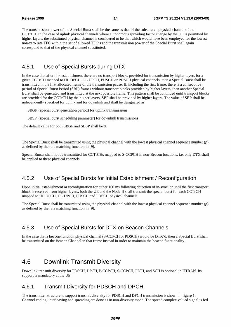
4.6.1 Transmit Diversity for PDSCH and DPCH The transmitter structure to support transmit diversity for PDSCH and DPCH transmission is shown in figure 1. Channel coding, interleaving and spreading are done as in non-diversity mode. The spread complex valued signal is fed
3GPP
3GPP TS 25.224 V3.13.0 (2003-09)15Release 1999
to both TX antenna branches, and weighted with antenna specific weight factors w1 and w2. The weight factors are complex valued signals (i.e., wi = ai + jbi ), in general. These weight factors are calculated on a per slot and per user basis.
The weight factors are determined by the UTRAN. Examples of transmit diversity schemes are given in annex B.
MUX
INTENCData
Midamble w1
w2
FIR RF
FIR RF
Uplink channel estimate
ANT1
ANT2SPR+SCR
Figure 1: Downlink transmitter structure to support Transmit Diversity for PDSCH and DPCH transmission (UTRAN Access Point)
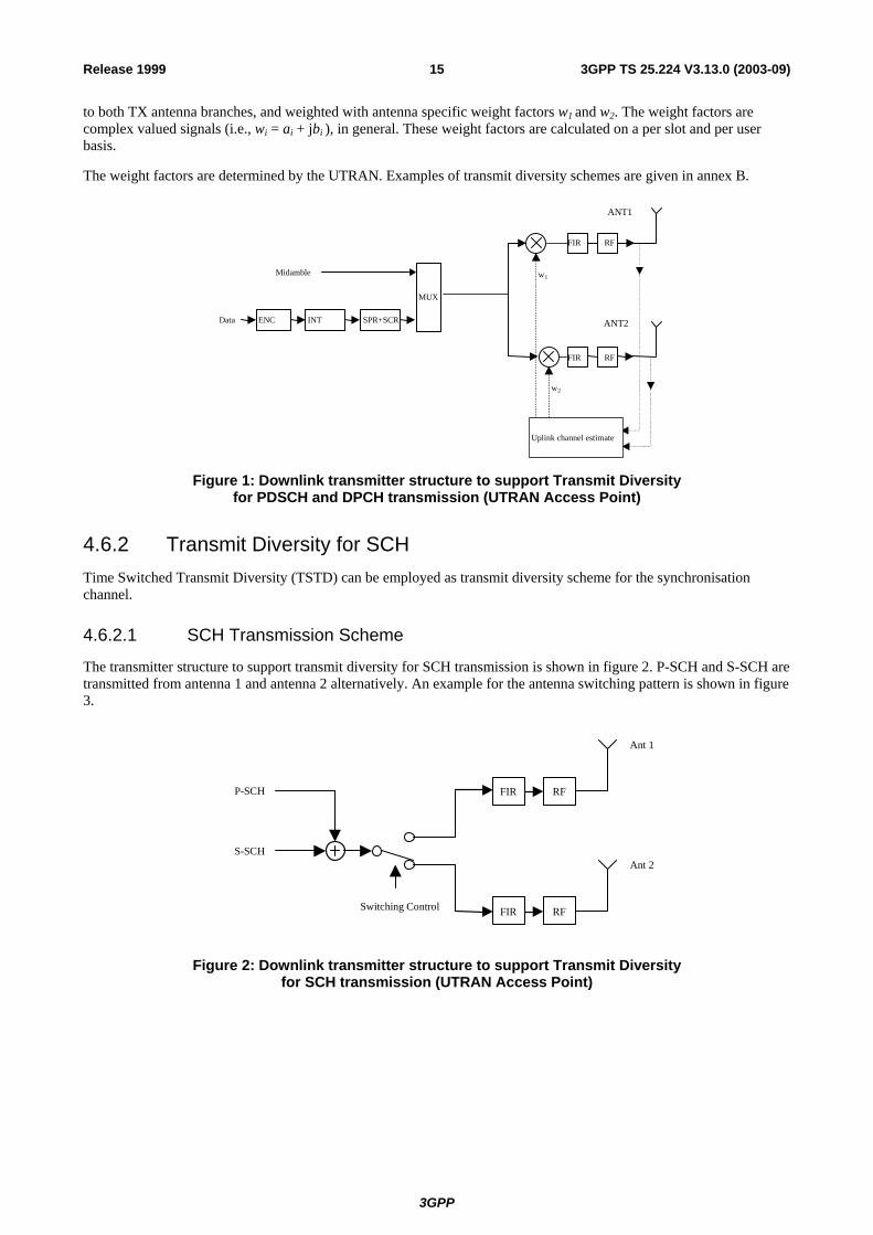
4.6.2 Transmit Diversity for SCH Time Switched Transmit Diversity (TSTD) can be employed as transmit diversity scheme for the synchronisation channel.
4.6.2.1 SCH Transmission Scheme
The transmitter structure to support transmit diversity for SCH transmission is shown in figure 2. P-SCH and S-SCH are transmitted from antenna 1 and antenna 2 alternatively. An example for the antenna switching pattern is shown in figure 3.
S-SCH
FIR RF
P-SCH
Ant 2
FIR RF
Ant 1
Switching Control
Figure 2: Downlink transmitter structure to support Transmit Diversity for SCH transmission (UTRAN Access Point)
3GPP
3GPP TS 25.224 V3.13.0 (2003-09)16Release 1999
Frame(15slot) Frame(15slot)
Ant #1
Ant #2
CP
b1c1
:
CP
b1c1
:
CP
b1c1
:
CP
b1c1
:
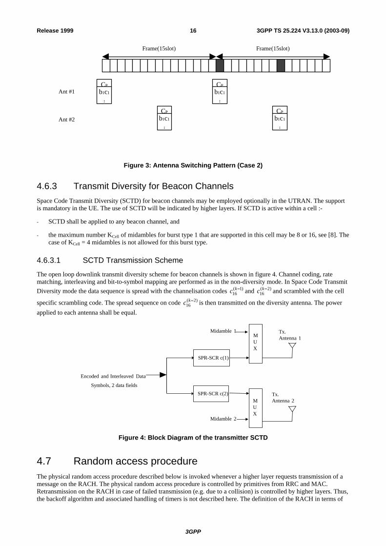
Figure 3: Antenna Switching Pattern (Case 2)
4.6.3 Transmit Diversity for Beacon Channels Space Code Transmit Diversity (SCTD) for beacon channels may be employed optionally in the UTRAN. The support is mandatory in the UE. The use of SCTD will be indicated by higher layers. If SCTD is active within a cell :-
- SCTD shall be applied to any beacon channel, and
- the maximum number KCell of midambles for burst type 1 that are supported in this cell may be 8 or 16, see [8]. The case of KCell = 4 midambles is not allowed for this burst type.
4.6.3.1 SCTD Transmission Scheme
The open loop downlink transmit diversity scheme for beacon channels is shown in figure 4. Channel coding, rate matching, interleaving and bit-to-symbol mapping are performed as in the non-diversity mode. In Space Code Transmit Diversity mode the data sequence is spread with the channelisation codes )1(
16=kc and )2(
16=kc and scrambled with the cell
specific scrambling code. The spread sequence on code )2(16
=kc is then transmitted on the diversity antenna. The power applied to each antenna shall be equal.
Tx.Antenna 1
Tx.Antenna 2
Encoded and Interleaved Data
Midamble 2
MUX
MUX
Midamble 1
SPR-SCR c(1)
SPR-SCR c(2) Symbols, 2 data fields
Figure 4: Block Diagram of the transmitter SCTD
4.7 Random access procedure The physical random access procedure described below is invoked whenever a higher layer requests transmission of a message on the RACH. The physical random access procedure is controlled by primitives from RRC and MAC. Retransmission on the RACH in case of failed transmission (e.g. due to a collision) is controlled by higher layers. Thus, the backoff algorithm and associated handling of timers is not described here. The definition of the RACH in terms of
3GPP
3GPP TS 25.224 V3.13.0 (2003-09)17Release 1999
PRACH Access Service Classes is broadcast on the BCH in each cell. Parameters for common physical channel uplink outer loop power control are also broadcast on the BCH in each cell. The UE needs to decode this information prior to transmission on the RACH.
4.7.1 Physical random access procedure The physical random access procedure described in this subclause is initiated upon request from the MAC sublayer (see [18] and [19]).
Note: The selection of a PRACH is done by the RRC Layer.
Before the physical random-access procedure can be initiated, Layer 1 shall receive the following information from the RRC layer using the primitives CPHY-TrCH-Config-REQ and CPHY-RL-Setup/Modify-REQ.
- the available PRACH channelization codes (There is a 1-1 mapping between the channelization code and the midamble shift as defined by RRC) for each Access Service Class (ASC) of the selected PRACH (the selection of a PRACH is done by the RRC ). CPHY-RL-Setup/Modify-REQ);
- the timeslot, spreading factor, and midamble type(direct or inverted) for the selected PRACH (CPHY-RL-Setup/Modify-REQ);
- the RACH Transport Format (CPHY-TrCH-Config-REQ);
- the RACH transport channel identity (CPHY-TrCH-Config-REQ)
- the set of parameters for common physical channel uplink outer loop power control(CPHY-RL-Setup/Modify-REQ).
NOTE: The above parameters may be updated from higher layers before each physical random access procedure is initiated.
At each initiation of the physical random access procedure, Layer 1 shall receive the following information from the MAC:
- the ASC of the PRACH transmission;
- the data to be transmitted (Transport Block Set).
- the selected ASC sub-channel. The ASC subchannel is defined in reference [18]. The value is passed in the PHY-Data-REQ is the CFNCELL.
The physical random-access procedure shall be performed as follows:
1 Randomly select one channelization code from the set of available codes for the selected ASC. The random function shall be such that each code is chosen with equal probability.
2 Determine the midamble shift to use, based on the selected channelization code.
3 Set the PRACH message transmission power level according to the specification for common physical channels in uplink (see subclause 4.2.2.2).
4 Transmit the RACH Transport Block Set (the random access message) with no timing advance in the selected sub-channel using the selected channelization code.
4.8 DSCH procedure The physical downlink shared channel procedure described below shall be applied by the UE when the physical layer signalling either with the midamble based signalling or TFCI based signalling is used to indicate for the UE the need for PDSCH detection. There is also a third alternative to indicate to the UE the need for the PDSCH detection and this is done by means of higher layer signalling, already described in [8].
3GPP
3GPP TS 25.224 V3.13.0 (2003-09)18Release 1999
4.8.1 DSCH procedure with TFCI indication When the UE has been allocated by higher layers to receive data on DSCH using the TFCI, the UE shall decode the PDSCH in the following cases:
- In case of a standalone PDSCH the TFCI is located on the PDSCH itself, then the UE shall decode the TFCI and based on which data rate was indicated by the TFCI, the decoding shall be performed. The UE shall decode PDSCH only if the TFCI word decode corresponds to the TFC part of the TFCS given to the UE by higher layers.
- In case that the TFCI is located on the DCH, the UE shall decode the PDSCH frame or frames if the TFCI on the DCH indicates the need for PDSCH reception. Upon reception of the DCH time slot or time slots, the PDSCH slot (or first PDSCH slot) shall start SFN n+2 after the DCH frame containing the TFCI, where n indicates the SFN on which the DCH is received. In the case that the TFCI is repeated over several frames, the PDSCH slot shall start SFN n+2 after the frame having the DCH slot which contains the last part of the repeated TFCI.
4.8.2 DSCH procedure with midamble indication When the UE has been allocated by higher layers to receive PDSCH based on the midamble used on the PDSCH (midamble based signalling described in [8]), the UE shall operate as follows:
- The UE shall test the midamble it received and if the midamble received was the same as indicated by higher layers to correspond to PDSCH reception, the UE shall detect the PDSCH data according to the TF given by the higher layers for the UE.
- In case of multiple time slot allocation for the DSCH indicated to be part of the TF for the UE, the UE shall receive all timeslots if the midamble of the first timeslot of PDSCH was the midamble indicated to the UE by higher layers.
- In case the standalone PDSCH (no associated DCH) contains the TFCI the UE shall detect the TF indicated by the TFCI on PDSCH.
3GPP
3GPP TS 25.224 V3.13.0 (2003-09)19Release 1999
Annex A (informative): Power Control
A.1 Example Implementation of Downlink Power Control in the UE
The power control may be realized by two cascaded control loops. The outer loop controls the transmission quality, whose reference value is set by higher layers [15], by providing the reference value for the inner loop. This reference value should be the SIR at the UE [15]. The inner loop controls the physical quantity for which the outer loop produces the reference value (e. g. the SIR) by generating TPC commands. This may be done by comparing the measured SIR to its reference value. When the measured value is higher than the target SIR value, TPC command = "down". When this is lower than or equal to the target SIR value, TPC command = "up".
In case of a downlink transmission pause on the DPCH or PDSCH, the receive power (RSCP) of the data can no longer be used for inner loop SIR calculations in the UE. In this case the UE should trace the fluctuations of the pathloss based on the P-CCPCH and use these values instead for generating the TPC commands. This pathloss together with the timeslot ISCP measurement in the data timeslot, which is ongoing, should be used to calculate a virtual SIR value:
SIRvirt(i) = RSCPvirt(i) − ISCP(i),
RSCPvirt(i) = RSCP0 + L0 – L(i) + ∑−
=
1
1)(
i
kkTPC ,
RSCP: Received signal code power in dBm ISCP: Interference signal code power in the DPCH / PDSCH timeslot in dBm L: pathloss in dB measured on the P-CCPCH. The same weighting of the long- and short-term pathloss
should be used as for uplink open loop power control, see Annex A.1 i: index for the frames during a transmission pause, 1 ≤ i ≤ number of frames in the pause L0: weighted pathloss in the last frame before the transmission pause in dB RSCP0: RSCP of the data that was used in the SIR calculation of the last frame before the pause in dBm TPC (k): ± power control stepsize in dB according to the TPC bit generated and transmitted in frame k, TPC bit
"up" = +stepsize, TPC bit "down" = −stepsize
3GPP
3GPP TS 25.224 V3.13.0 (2003-09)20Release 1999
Annex B (informative): Determination of Weight Information Selective Transmit Diversity (STD) and Transmit Adaptive Antennas (TxAA) are examples of transmit diversity schemes for dedicated physical channels.
B.1 STD Weights The weight vector will take only two values depending on the signal strength received by each antenna in the uplink slot. For each user, the antenna receiving the highest power will be selected (i.e. the corresponding weight will be set to 1).
Table 2: STD weights for two TX antennas
W1 W2Antenna 1 receiving highest power 1 0 Antenna 2 receiving highest power 0 1
B.2 TxAA Weights In a generic sense, the weight vector to be applied at the transmitter is the w that maximises:
P=wHHHHw (1)
where
H=[h1 h2] and w = [ w1, w2 ]T
and where the column vector hi represents the estimated uplink channel impulse response for the i'th transmission antenna, of length equal to the length of the channel impulse response.
3GPP
3GPP TS 25.224 V3.13.0 (2003-09)21Release 1999
Annex C (informative): Cell search procedure During the cell search, the UE searches for a cell and determines the downlink scrambling code, basic midamble code and frame synchronisation of that cell. The cell search is typically carried out in three steps:
Step 1: Primary synchronisation code acquisition
During the first step of the cell search procedure, the UE uses the SCH's primary synchronisation code to find a cell. This is typically done with a single matched filter (or any similar device) matched to the primary synchronisation code which is common to all cells. A cell can be found by detecting peaks in the matched filter output.
Note that for a cell of SCH slot configuration case 1, the SCH can be received periodically every 15 slots. In case of a cell of SCH slot configuration case 2, the following SCH slot can be received at offsets of either 7 or 8 slots from the previous SCH slot.
Step 2: Code group identification and slot synchronisation
During the second step of the cell search procedure, the UE uses the SCH's secondary synchronisation codes to identify 1 out of 32 code groups for the cell found in the first step. This is typically done by correlating the received signal with the secondary synchronisation codes at the detected peak positions of the first step. The primary synchronisation code provides the phase reference for coherent detection of the secondary synchronisation codes. The code group can then uniquely be identified by detection of the maximum correlation values.
Each code group indicates a different toffset parameter and 4 specific cell parameters. Each of the cell parameters is associated with one particular downlink scrambling code and one particular long and short basic midamble code. When the UE has determined the code group, it can unambiguously derive the slot timing of the found cell from the detected peak position in the first step and the toffset parameter of the found code group in the second step.
Note that the modulation of the secondary synchronisation codes also indicates the position of the SCH slot within a 2 frames period, e.g. a frame with even or odd SFN. Additionally, in the case of SCH slot configuration following case 2, the SCH slot position within one frame, e.g. first or last SCH slot, can be derived from the modulation of the secondary synchronisation codes.
Step 3: Downlink scrambling code, basic midamble code identification and frame synchronisation
During the third and last step of the cell search procedure, the UE determines the exact downlink scrambling code, basic midamble code and frame timing used by the found cell. The long basic midamble code can be identified by correlation over the P-CCPCH (or any other beacon channel) with the 4 possible long basic midamble codes of the code group found in the second step. A P-CCPCH (or any other beacon channel) always uses the midamble m(1) (and in case of SCTD also midamble m(2)) derived from the long basic midamble code and always uses a fixed and pre-assigned channelisation code.
When the long basic midamble code has been identified, downlink scrambling code and cell parameter are also known. The UE can read system and cell specific BCH information and acquire frame synchronisation.
Note that even for an initial cell parameter assignment, a cell cycles through a set composed of 2 different cell parameters according to the SFN of a frame, e.g. the downlink scrambling code and the basic midamble code of a cell alternate for frames with even and odd SFN. Cell parameter cycling leaves the code group of a cell unchanged.
If the UE has received information about which cell parameters or SCH configurations to search for, cell search can be simplified.
3GPP
3GPP TS 25.224 V3.13.0 (2003-09)22Release 1999
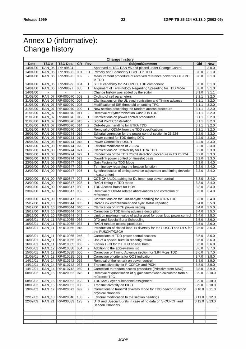
Annex D (informative): Change history
Change history Date TSG # TSG Doc. CR Rev Subject/Comment Old New
14/01/00 RAN_05 RP-99594 - Approved at TSG RAN #5 and placed under Change Control - 3.0.014/01/00 RAN_06 RP-99698 001 01 Primary and Secondary CCPCH in TDD 3.0.0 3.1.014/01/00 RAN_06 RP-99698 002 - Measurement procedure of received reference power for OL-TPC
in TDD 3.0.0 3.1.0
14/01/00 RAN_06 RP-99699 004 1 STTD capability for P-CCPCH, TDD component 3.0.0 3.1.014/01/00 RAN_06 RP-99697 005 1 Alignment of Terminology Regarding Spreading for TDD Mode 3.0.0 3.1.014/01/00 - - - Change history was added by the editor 3.1.0 3.1.131/03/00 RAN_07 RP-000070 003 2 Cycling of cell parameters 3.1.1 3.2.031/03/00 RAN_07 RP-000070 007 2 Clarifications on the UL synchronisation and Timing advance 3.1.1 3.2.031/03/00 RAN_07 RP-000070 008 - Modification of SIR threshold on setting TPC 3.1.1 3.2.031/03/00 RAN_07 RP-000070 009 1 New section describing the random access procedure 3.1.1 3.2.031/03/00 RAN_07 RP-000070 011 - Removal of Synchronisation Case 3 in TDD 3.1.1 3.2.031/03/00 RAN_07 RP-000070 012 1 Clarifications on power control procedures 3.1.1 3.2.031/03/00 RAN_07 RP-000070 013 - Signal Point Constellation 3.1.1 3.2.031/03/00 RAN_07 RP-000070 014 2 Out-of-sync handling for UTRA TDD 3.1.1 3.2.031/03/00 RAN_07 RP-000070 015 - Removal of ODMA from the TDD specifications 3.1.1 3.2.026/06/00 RAN_08 RP-000274 016 - Editorial correction for the power control section in 25.224 3.2.0 3.3.026/06/00 RAN_08 RP-000274 017 - Power control for TDD during DTX 3.2.0 3.3.026/06/00 RAN_08 RP-000274 018 1 Power Control for PDSCH 3.2.0 3.3.026/06/00 RAN_08 RP-000274 020 1 Editorial modification of 25.224 3.2.0 3.3.026/06/00 RAN_08 RP-000274 021 - Clarifications on TxDiversity for UTRA TDD 3.2.0 3.3.026/06/00 RAN_08 RP-000274 022 1 Introduction of the TDD DSCH detection procedure in TS 25.224 3.2.0 3.3.026/06/00 RAN_08 RP-000274 023 - Downlink power control on timeslot basis 3.2.0 3.3.023/09/00 RAN_09 RP-000347 019 1 Gain Factors for TDD Mode 3.3.0 3.4.023/09/00 RAN_09 RP-000347 025 - Terminology regarding the beacon function 3.3.0 3.4.023/09/00 RAN_09 RP-000347 026 1 Synchronisation of timing advance adjustment and timing deviation
measurement 3.3.0 3.4.0
23/09/00 RAN_09 RP-000347 027 1 CCTrCH UL/DL pairing for DL inner loop power control 3.3.0 3.4.023/09/00 RAN_09 RP-000347 028 1 RACH timing in TDD mode 3.3.0 3.4.023/09/00 RAN_09 RP-000347 030 1 TDD Access Bursts for HOV 3.3.0 3.4.023/09/00 RAN_09 RP-000347 032 - Removal of ODMA related abbreviations and correction of
references 3.3.0 3.4.0
23/09/00 RAN_09 RP-000347 033 - Clarifications on the Out-of-sync handling for UTRA TDD 3.3.0 3.4.015/12/00 RAN_10 RP-000544 035 1 Radio Link establishment and sync status reporting 3.4.0 3.5.015/12/00 RAN_10 RP-000544 040 - Clarification on PICH power setting 3.4.0 3.5.015/12/00 RAN_10 RP-000544 042 - Correction to TDD timing advance description 3.4.0 3.5.015/12/00 RAN_10 RP-000544 043 - Limit on maximum value of alpha used for open loop power control 3.4.0 3.5.016/03/01 RAN_11 RP-010065 036 - DTX and Special Burst Scheduling 3.5.0 3.6.016/03/01 RAN_11 RP-010065 037 1 RACH random access procedure 3.5.0 3.6.016/03/01 RAN_11 RP-010065 045 - Introduction of closed-loop Tx diversity for the PDSCH and DTX for
the PUSCH/PDSCH 3.5.0 3.6.0
16/03/01 RAN_11 RP-010065 046 2 Corrections of TDD power control sections 3.5.0 3.6.016/03/01 RAN_11 RP-010065 050 - Use of a special burst in reconfiguration 3.5.0 3.6.016/03/01 RAN_11 RP-010065 053 - Known TFCI for the TDD special burst 3.5.0 3.6.015/06/01 RAN_12 RP-010338 054 2 Addition to the abbreviation list 3.6.0 3.7.015/06/01 RAN_12 RP-010338 056 - Correction of Timing Advance section for 3.84 Mcps TDD 3.6.0 3.7.021/09/01 RAN_13 RP-010525 063 1 Correction of criteria for OOS indication 3.7.0 3.8.014/12/01 RAN_14 RP-010742 065 - Removal of the remark on power control 3.8.0 3.9.014/12/01 RAN_14 RP-010742 067 1 Transmit diversity for P-CCPCH and PICH 3.8.0 3.9.014/12/01 RAN_14 RP-010742 069 1 Correction to random access procedure (Primitive from MAC) 3.8.0 3.9.008/03/02 RAN_15 RP-020052 078 1 Removal of quantisation of bj gain factor when calculated from a
reference TFC 3.9.0 3.10.0
08/03/02 RAN_15 RP-020052 083 1 TDD MAC layer subchannel assignment 3.9.0 3.10.008/03/02 RAN_15 RP-020052 085 - Transmit diversity on PICH 3.9.0 3.10.019/09/02 RAN_17 RP-020572 092 2 Corrections to transmit diversity mode for TDD beacon-function
physical channels 3.10.0 3.11.0
22/12/02 RAN_18 RP-020840 103 - Editorial modification to the section headings 3.11.0 3.12.022/09/03 RAN_21 RP-030533 123 2 DTX and Special Bursts in case of no data on S-CCPCH and
Beacon Channels 3.12.0 3.13.0

3GPP
3GPP TS 25.224 V3.13.0 (2003-09)23Release 1999