Embed Size (px)
Citation preview

CR page 1
3GPP TS 25.309 V6.3.0 (2005-06)Technical Specification
3rd Generation Partnership Project;Technical Specification Group Radio Access Network;
FDD Enhanced Uplink;Overall description;
Stage 2(Release 6)
The present document has been developed within the 3rd Generation Partnership Project (3GPP TM) and may be further elaborated for the purposes of 3GPP. The present document has not been subject to any approval process by the 3GPP Organizational Partners and shall not be implemented. This Specification is provided for future development work within 3GPP only. The Organizational Partners accept no liability for any use of this Specification.Specifications and reports for implementation of the 3GPP TM system should be obtained via the 3GPP Organizational Partners’ Publications Offices.

3GPP
3GPP TS 25.309 V6.3.0 (2005-06)2Release 6
Keywords UMTS, data, stage 2
3GPP
Postal address
3GPP support office address 650 Route des Lucioles – Sophia Antipolis
Valbonne - France Tel.: +33 4 92 94 42 00 Fax: +33 4 93 65 47 16
Internet http://www.3gpp.org
Copyright Notification
No part may be reproduced except as authorized by written permission. The copyright and the foregoing restriction extend to reproduction in all media.
© 2005, 3GPP Organizational Partners (ARIB, ATIS, CCSA, ETSI, TTA, TTC).
All rights reserved.
3GPP
3GPP TS 25.309 V6.3.0 (2005-06)3Release 6
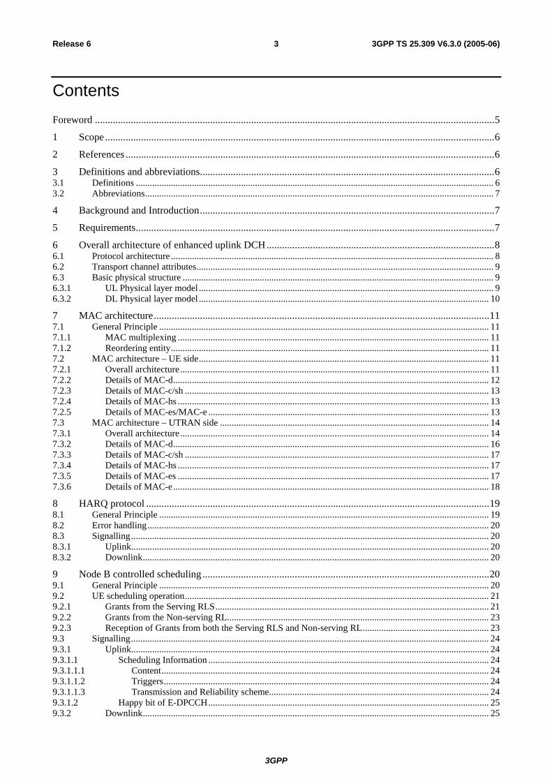
Contents Foreword ............................................................................................................................................................5 1 Scope ........................................................................................................................................................6 2 References ................................................................................................................................................6 3 Definitions and abbreviations...................................................................................................................6 3.1 Definitions ......................................................................................................................................................... 6 3.2 Abbreviations..................................................................................................................................................... 7 4 Background and Introduction...................................................................................................................7 5 Requirements............................................................................................................................................7 6 Overall architecture of enhanced uplink DCH.........................................................................................8 6.1 Protocol architecture .......................................................................................................................................... 8 6.2 Transport channel attributes............................................................................................................................... 9 6.3 Basic physical structure ..................................................................................................................................... 9 6.3.1 UL Physical layer model .............................................................................................................................. 9 6.3.2 DL Physical layer model ............................................................................................................................ 10 7 MAC architecture...................................................................................................................................11 7.1 General Principle ............................................................................................................................................. 11 7.1.1 MAC multiplexing ..................................................................................................................................... 11 7.1.2 Reordering entity........................................................................................................................................ 11 7.2 MAC architecture – UE side............................................................................................................................ 11 7.2.1 Overall architecture.................................................................................................................................... 11 7.2.2 Details of MAC-d....................................................................................................................................... 12 7.2.3 Details of MAC-c/sh .................................................................................................................................. 13 7.2.4 Details of MAC-hs ..................................................................................................................................... 13 7.2.5 Details of MAC-es/MAC-e ........................................................................................................................ 13 7.3 MAC architecture – UTRAN side ................................................................................................................... 14 7.3.1 Overall architecture.................................................................................................................................... 14 7.3.2 Details of MAC-d....................................................................................................................................... 16 7.3.3 Details of MAC-c/sh .................................................................................................................................. 17 7.3.4 Details of MAC-hs ..................................................................................................................................... 17 7.3.5 Details of MAC-es ..................................................................................................................................... 17 7.3.6 Details of MAC-e....................................................................................................................................... 18 8 HARQ protocol ......................................................................................................................................19 8.1 General Principle ............................................................................................................................................. 19 8.2 Error handling.................................................................................................................................................. 20 8.3 Signalling......................................................................................................................................................... 20 8.3.1 Uplink......................................................................................................................................................... 20 8.3.2 Downlink.................................................................................................................................................... 20 9 Node B controlled scheduling ................................................................................................................20 9.1 General Principle ............................................................................................................................................. 20 9.2 UE scheduling operation.................................................................................................................................. 21 9.2.1 Grants from the Serving RLS..................................................................................................................... 21 9.2.2 Grants from the Non-serving RL................................................................................................................ 23 9.2.3 Reception of Grants from both the Serving RLS and Non-serving RL...................................................... 23 9.3 Signalling......................................................................................................................................................... 24 9.3.1 Uplink......................................................................................................................................................... 24 9.3.1.1 Scheduling Information ........................................................................................................................ 24 9.3.1.1.1 Content............................................................................................................................................ 24 9.3.1.1.2 Triggers........................................................................................................................................... 24 9.3.1.1.3 Transmission and Reliability scheme.............................................................................................. 24 9.3.1.2 Happy bit of E-DPCCH........................................................................................................................ 25 9.3.2 Downlink.................................................................................................................................................... 25

3GPP
3GPP TS 25.309 V6.3.0 (2005-06)4Release 6
10 Non-scheduled transmissions.................................................................................................................25 11 QoS control ............................................................................................................................................26 11.1 General Principle ............................................................................................................................................. 26 11.1.1 QoS configuration principles ..................................................................................................................... 26 11.2 TFC and E-TFC selection ................................................................................................................................ 27 11.3 Setting of Power offset attributes of MAC-d flows ......................................................................................... 28 12 Signalling parameters.............................................................................................................................28 12.1 Uplink signalling parameters ........................................................................................................................... 28 12.2 Downlink signalling parameters ...................................................................................................................... 29 13 Mobility procedures ...............................................................................................................................30 13.1 Change of serving cell and/or serving RLS ..................................................................................................... 30 14 Resource Management ...........................................................................................................................30 14.1 Scheduler control from CRNC to Node B ....................................................................................................... 30 14.2 Node B to CRNC reporting.............................................................................................................................. 31
Annex A (informative): Change history ...............................................................................................33

3GPP
3GPP TS 25.309 V6.3.0 (2005-06)5Release 6
Foreword This Technical Specification has been produced by the 3rd Generation Partnership Project (3GPP).
The contents of the present document are subject to continuing work within the TSG and may change following formal TSG approval. Should the TSG modify the contents of the present document, it will be re-released by the TSG with an identifying change of release date and an increase in version number as follows:
Version x.y.z
where:
x the first digit:
1 presented to TSG for information;
2 presented to TSG for approval;
3 or greater indicates TSG approved document under change control.
y the second digit is incremented for all changes of substance, i.e. technical enhancements, corrections, updates, etc.
z the third digit is incremented when editorial only changes have been incorporated in the document.
3GPP
3GPP TS 25.309 V6.3.0 (2005-06)6Release 6
1 Scope The present document is a technical specification of the overall support of FDD Enhanced Uplink in UTRA.
2 References The following documents contain provisions which, through reference in this text, constitute provisions of the present document.
• References are either specific (identified by date of publication, edition number, version number, etc.) or non-specific.
• For a specific reference, subsequent revisions do not apply.
• For a non-specific reference, the latest version applies. In the case of a reference to a 3GPP document (including a GSM document), a non-specific reference implicitly refers to the latest version of that document in the same Release as the present document.
[1] 3GPP TR 25.896: "Feasibility Study for Enhanced Uplink for UTRA FDD".
[2] 3GPP TR 21.905: "Vocabulary for 3GPP Specifications".
[3] 3GPP TS 25.214: "Physical layer procedures (FDD)".
3 Definitions and abbreviations
3.1 Definitions For the purposes of the present document, the terms and definitions given in 3GPP TR 21.905 [2] and the following apply:
Active Process: HARQ process for which the Scheduling Grant applies, i.e. scheduled data can be sent.
Data Description Indicator (DDI): MAC-e header field used to identify the logical channel, MAC-d flow and the size of the MAC-d PDUs concatenated into a MAC-es PDU.
E-DCH: Enhanced DCH, a new dedicated transport channel type or enhancements to an existing dedicated transport channel type.
E-DCH active set: The set of cells which carry the E-DCH for one UE.
HARQ profile: One HARQ profile consists of a power offset attribute and maximum number of transmissions.
Inactive Process: HARQ process for which the Scheduling Grant does not apply, i.e. scheduled data cannot be sent.
INACTIVE: Absolute Grant value that can be sent by the serving cell's scheduler on the E-AGCH scheduling grant to deactivate a process or to switch the UE to its secondary E-RNTI
Power offset attribute: Represents the power offset between E-DPDCH(s) and reference E-DPDCH power level for a given E-TFC. This power offset attribute is set to achieve the required QoS in this MAC-d flow when carried alone in a MAC-e PDU and subsequently in the corresponding CCTrCh of E-DCH type. Details on the mapping on Beta factors can be found in RAN WG1 specifications. The reference E-DPDCH power level for a given E-TFC is signaled to the UE for a reference E-TFC (see details in subclause 11.1).
Primary Absolute Grant: Absolute Grant received with the primary E-RNTI.
Secondary Absolute Grant: Absolute Grant received with the secondary E-RNTI.

3GPP
3GPP TS 25.309 V6.3.0 (2005-06)7Release 6
Serving E-DCH cell: Cell from which the UE receives Absolute Grants from the Node-B scheduler. A UE has one Serving E-DCH cell.
Serving E-DCH RLS or Serving RLS: Set of cells which contains at least the Serving E-DCH cell and from which the UE can receive and combine one Relative Grant. The UE has only one Serving E-DCH RLS.
Non-serving E-DCH RL or Non-serving RL: Cell which belongs to the E-DCH active set but does not belong to the Serving E-DCH RLS and from which the UE can receive one Relative Grant. The UE can have zero, one or several Non-serving E-DCH RL(s).
3.2 Abbreviations For the purposes of the present document, the abbreviations given in 3GPP TR 21.905 [2] and the following apply:
AG Absolute Grant E-AGCH E-DCH Absolute Grant Channel E-DPCCH E-DCH Dedicated Physical Control Channel E-DPDCH E-DCH Dedicated Physical Data Channel E-HICH E-DCH HARQ Acknowledgement Indicator Channel E-RGCH E-DCH Relative Grant Channel E-RNTI E-DCH Radio Network Temporary Identifier E-TFC E-DCH Transport Format Combination HARQ Hybrid Automatic Repeat Request HSDPA High Speed Downlink Packet Access RG Relative Grant RLS Radio Link Set RSN Retransmission Sequence Number SG Serving Grant TSN Transmission Sequence Number
4 Background and Introduction The technical objective of the FDD Enhanced Uplink work item is to improve the performance of uplink dedicated transport channels, i.e. to increase capacity and throughput and reduce delay. This work item is applicable for UTRA FDD only.
Among the techniques considered in [1], the following techniques are part of the work item:
- Node B controlled scheduling: possibility for the Node B to control, within the limits set by the RNC, the set of TFCs from which the UE may choose a suitable TFC,
- Hybrid ARQ: rapid retransmissions of erroneously received data packets between UE and Node B,
- Shorter TTI: possibility of introducing a 2 ms TTI.
5 Requirements - The Enhanced Uplink feature shall aim at providing significant enhancements in terms of user experience
(throughput and delay) and/or capacity. The coverage is an important aspect of the user experience and that it is desirable to allow an operator to provide for consistency of performance across the whole cell area.
- The focus shall be on urban, sub-urban and rural deployment scenarios.
- Full mobility shall be supported, i.e., mobility should be supported for high-speed cases also, but optimisation should be for low-speed to medium-speed scenarios.
- The study shall investigate the possibilities to enhance the uplink performance on the dedicated transport channels in general, with priority to streaming, interactive and background services. Relevant QoS mechanisms shall allow the support of streaming, interactive and background PS services.
3GPP
3GPP TS 25.309 V6.3.0 (2005-06)8Release 6
- It is highly desirable to keep the Enhanced Uplink as simple as possible. New techniques or group of techniques shall therefore provide significant incremental gain for an acceptable complexity. The value added per feature/technique should be considered in the evaluation. It is also desirable to avoid unnecessary options in the specification of the feature.
- The UE and network complexity shall be minimised for a given level of system performance.
- The impact on current releases in terms of both protocol and hardware perspectives shall be taken into account.
- It shall be possible to introduce the Enhanced Uplink feature in a network which has terminals from Release’99, Release 4 and Release 5. The Enhanced Uplink feature shall enable to achieve significant improvements in overall system performance when operated together with HSDPA. Emphasis shall be given on the potential impact the new feature may have on the downlink capacity. Likewise it shall be possible to deploy the Enhanced Uplink feature without any dependency on the deployment of the HSDPA feature. However, a terminal supporting the Enhanced Uplink feature must support HSDPA.
6 Overall architecture of enhanced uplink DCH
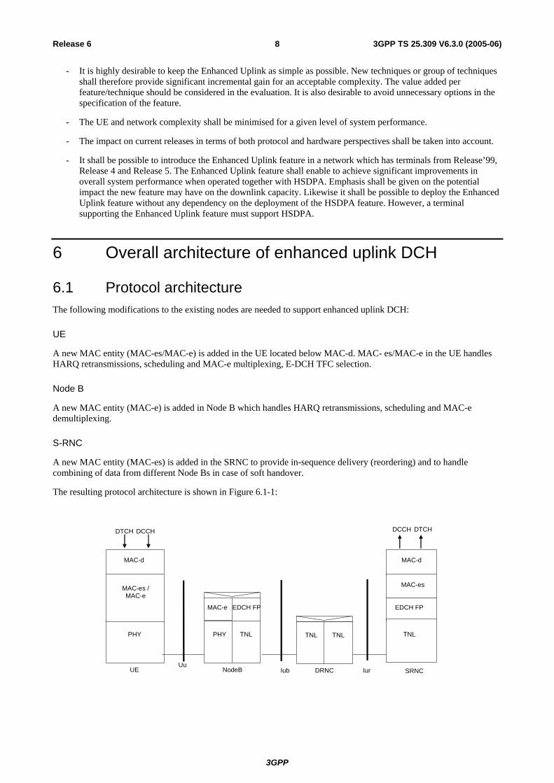
6.1 Protocol architecture The following modifications to the existing nodes are needed to support enhanced uplink DCH:
UE
A new MAC entity (MAC-es/MAC-e) is added in the UE located below MAC-d. MAC- es/MAC-e in the UE handles HARQ retransmissions, scheduling and MAC-e multiplexing, E-DCH TFC selection.
Node B
A new MAC entity (MAC-e) is added in Node B which handles HARQ retransmissions, scheduling and MAC-e demultiplexing.
S-RNC
A new MAC entity (MAC-es) is added in the SRNC to provide in-sequence delivery (reordering) and to handle combining of data from different Node Bs in case of soft handover.
The resulting protocol architecture is shown in Figure 6.1-1:
PHY PHY
EDCH FP EDCH FP
IubUE NodeBUu
DCCH DTCH
TNL TNL
DTCH DCCH
MAC-e
SRNC
MAC-d
MAC-e
MAC-d
MAC-es / MAC-e
MAC-es
Iur
TNL TNL
DRNC

3GPP
3GPP TS 25.309 V6.3.0 (2005-06)9Release 6
Figure 6.1-1: Protocol Architecture of E-DCH
The need for an E-DCH FP in the DRNC has to be discussed (this is under the scope of RAN WG3).
6.2 Transport channel attributes The E-DCH transport channel has the following characteristics:
- E-DCH and DCH are using separate CCTrCHs
- There is only one CCTrCH of E-DCH type per UE;
- There is only one E-DCH per CCTrCH of E-DCH type;
- There is only one transport block per TTI;
- Both 2 ms TTI and 10 ms TTI are supported by the E-DCH. The support of 10 ms TTI is mandatory for all UEs. The support of the 2 ms TTI by the UE is only mandatory for certain UE categories. Switching between the two TTIs can be performed by UTRAN through L3 signalling;
- For all UE categories, the uplink DCH CCTrCH data rate is limited to 64kbps when E-DCH is configured for the radio link.
6.3 Basic physical structure
6.3.1 UL Physical layer model E-DCH model with DCH and HS-DSCH
Coded Composite Transport Channel
CCTrCH)
Phy CH Phy CH
TPC & TFCI
(
Physical Channel Data Streams
Demultiplexing /Splitting
DCH
Coding andmultiplexing
Phy CH
DCH
.....
.....
Phy CH
ACK/NACKCQI Physical Channel
Data Streams
Demultiplexing /Splitting
E-DCH
Coding and multiplexing
Phy CH
.....
Coded Composite Transport Channel
CCTrCH)
Phy CH
E-DCH TFCI E-DCH HARQ
Phy CH
Figure 6.3.1-1: Model of the UE's Uplink physical layer
There is only one E-DCH per CCTrCh of E-DCH type.
For both 2 ms and 10 ms TTI, the information carried on the E-DPCCH consists of 10 bits in total: the E-TFI (7 bits), the RSN (2 bits) and the ‘happy’ bit (see in subclause 9.3.1.2).
3GPP
3GPP TS 25.309 V6.3.0 (2005-06)10Release 6
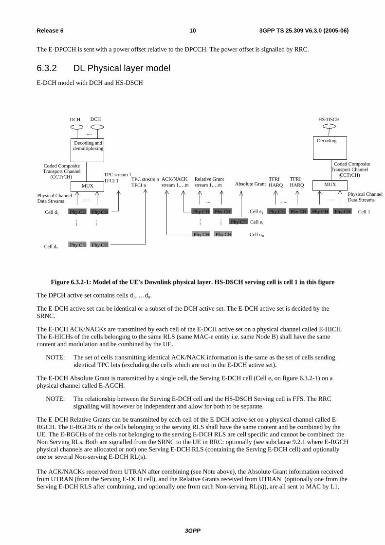
The E-DPCCH is sent with a power offset relative to the DPCCH. The power offset is signalled by RRC.
6.3.2 DL Physical layer model E-DCH model with DCH and HS-DSCH
ACK/NACK stream 1,…m
TPC stream 1 TFCI 1
TPC stream n TFCI n
Phy CHPhy CH
Phy CH Phy CH
.....
.....
.....
Relative Grant stream 1,…m
Cell es
Absolute GrantTFRI HARQ
TFRI HARQ
Cell e1
Cell em
Coded Composite
(
Phy CH Phy CH
HS-DSCH
Phy CH
Cell d1
Cell dn
Cell 1
Coded Composite Transport Channel
( CCTrCH)
Physical Channel Data Streams
MUX
DCH
Decoding and demultiplexing
Phy CH Phy CH
Phy CH Phy CH
DCH
.....
.....
.....
.....
Decoding
Transport ChannelCCTrCH)
MUX
..... Data StreamsPhysical Channel
Phy CH Phy CH
.....
Figure 6.3.2-1: Model of the UE's Downlink physical layer. HS-DSCH serving cell is cell 1 in this figure
The DPCH active set contains cells d1, …dn.
The E-DCH active set can be identical or a subset of the DCH active set. The E-DCH active set is decided by the SRNC.
The E-DCH ACK/NACKs are transmitted by each cell of the E-DCH active set on a physical channel called E-HICH. The E-HICHs of the cells belonging to the same RLS (same MAC-e entity i.e. same Node B) shall have the same content and modulation and be combined by the UE.
NOTE: The set of cells transmitting identical ACK/NACK information is the same as the set of cells sending identical TPC bits (excluding the cells which are not in the E-DCH active set).
The E-DCH Absolute Grant is transmitted by a single cell, the Serving E-DCH cell (Cell es on figure 6.3.2-1) on a physical channel called E-AGCH.
NOTE: The relationship between the Serving E-DCH cell and the HS-DSCH Serving cell is FFS. The RRC signalling will however be independent and allow for both to be separate.
The E-DCH Relative Grants can be transmitted by each cell of the E-DCH active set on a physical channel called E-RGCH. The E-RGCHs of the cells belonging to the serving RLS shall have the same content and be combined by the UE. The E-RGCHs of the cells not belonging to the serving E-DCH RLS are cell specific and cannot be combined: the Non Serving RLs. Both are signalled from the SRNC to the UE in RRC: optionally (see subclause 9.2.1 where E-RGCH physical channels are allocated or not) one Serving E-DCH RLS (containing the Serving E-DCH cell) and optionally one or several Non-serving E-DCH RL(s). The ACK/NACKs received from UTRAN after combining (see Note above), the Absolute Grant information received from UTRAN (from the Serving E-DCH cell), and the Relative Grants received from UTRAN (optionally one from the Serving E-DCH RLS after combining, and optionally one from each Non-serving RL(s)), are all sent to MAC by L1.
3GPP
3GPP TS 25.309 V6.3.0 (2005-06)11Release 6
7 MAC architecture
7.1 General Principle
7.1.1 MAC multiplexing The E-DCH MAC multiplexing has the following characteristics:
- Logical channel multiplexing is supported at MAC-e level;
- Multiple MAC-d flows can be configured for one UE;
- The multiplexing of different MAC-d flows within the same MAC-e PDU is supported. But not all the combinations may be allowed for one UE. The allowed combinations are under the control of the SRNC. (See in clause 11);
- There can be up to 8 MAC-d flows for a UE;
- Up to 16 logical channels can be multiplexed on an E-DCH transport channel.
7.1.2 Reordering entity The re-ordering entity is part of a separate MAC sub-layer, MAC-es, in the SRNC. Data coming from different MAC-d flows are reordered in different reordering queues. There is one reordering queue per logical channel.
The reordering is based on a specific TSN included in the MAC-es PDU and on Node-B tagging with a (CFN, subframe number). For each MAC-es PDU, the SRNC receives the TSN originating from the UE, as well as the (CFN, subframe number) originating from the Node-B to perform the re-ordering. Additional mechanisms (e.g. timer-based and/or window-based) are up to SRNC implementation and will not be standardised. Furthermore, the reordering entity detects and removes duplicated received MAC-es PDUs.
7.2 MAC architecture – UE side
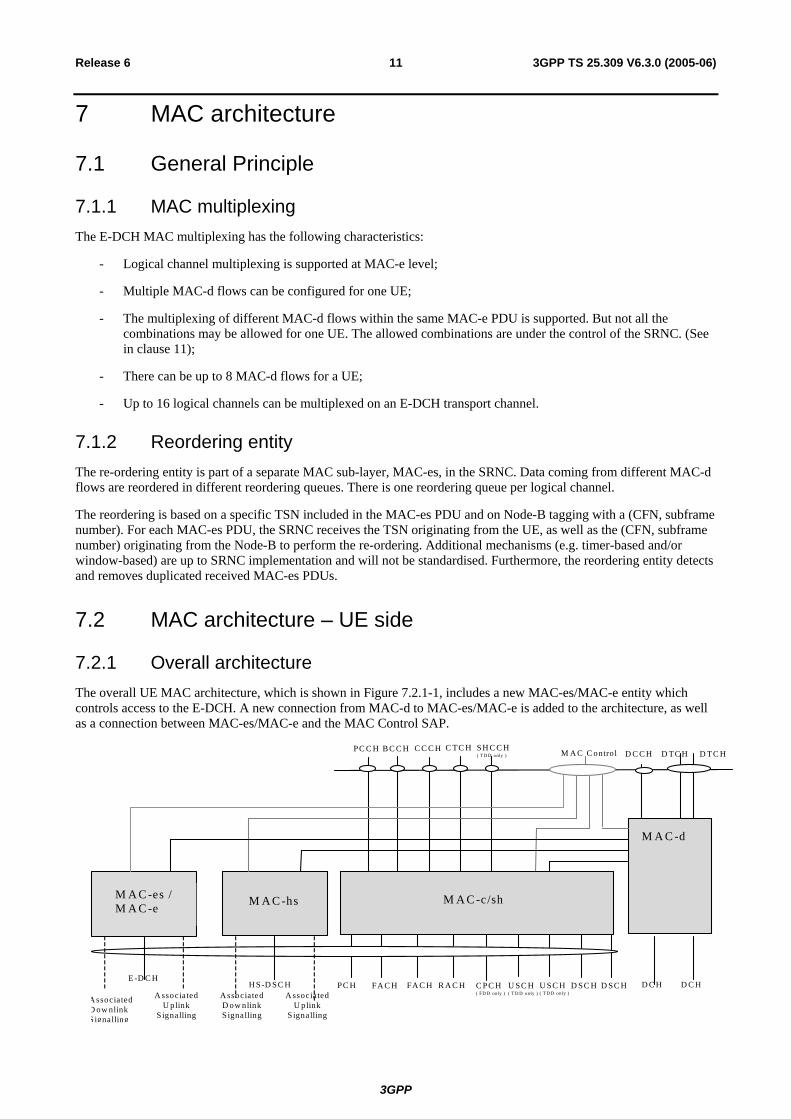
7.2.1 Overall architecture The overall UE MAC architecture, which is shown in Figure 7.2.1-1, includes a new MAC-es/MAC-e entity which controls access to the E-DCH. A new connection from MAC-d to MAC-es/MAC-e is added to the architecture, as well as a connection between MAC-es/MAC-e and the MAC Control SAP.
A ssociated D ow nlink S ignalling
E -D C H
M A C -d
FA C H R A C H
D C C H D TC H D TC H
D SC H D C H D C H
M A C C ontrol
U SC H ( T D D only )
C PC H ( FD D only )
C TC H B C C H C C C H SH C C H( T D D only )
PC C H
PC H FA C H
M A C -c/sh
U SC H ( T D D only )
D SC H
M A C -hs
H S-D SC H A ssocia ted
U plink S ignalling
A ssocia ted D ow nlink S ignalling
M A C -es / M A C -e
A ssociated U plink
S ignalling

3GPP
3GPP TS 25.309 V6.3.0 (2005-06)12Release 6
Figure 7.2.1-1: UE side MAC architecture
As shown in Figure 7.2.1-2, a RLC PDU enters MAC-d on a logical channel. The MAC-d C/T multiplexing is bypassed. In the MAC-e header, the DDI (Data Description Indicator) field (6 bits) identifies logical channel, MAC-d flow and MAC-d PDU size. A mapping table is signalled over RRC, to allow the UE to set DDI values. The N field (fixed size of 6 bits) indicates the number of consecutive MAC-d PDUs corresponding to the same DDI value. A special value of the DDI field indicates that no more data is contained in the remaining part of the MAC-e PDU.The TSN field (6 bits) provides the transmission sequence number on the E-DCH. The MAC-e PDU is forwarded to a Hybrid ARQ entity, which then forwards the MAC-e PDU to layer 1 for transmission in one TTI.
MAC-d Flows
MAC-es PDU MAC-e header
DCCH DTCH DTCH
HARQ processes
Multiplexing
DATA
MAC-d DATA
DATA
DDI N Padding (Opt)
RLC PDU:
MAC-e PDU:
L1
RLC
DDI N
Mapping info signaled over RRC PDU size, logical channel id, MAC-d flow id => DDI
DATA DATA
MAC-d PDU:
DDI
Header
MAC-es/e
Numbering MAC-es PDU: TSN DATA DATA Numbering Numbering
Figure 7.2.1-2: Simplified architecture showing MAC inter-working in UE. The left part shows the functional split while the right part shows PDU construction.
7.2.2 Details of MAC-d For support of E-DCH a new connection to MAC-es is added.

3GPP
3GPP TS 25.309 V6.3.0 (2005-06)13Release 6
DCCH DTCH DTCH
DCH DCH
MAC-d
from MAC-hs
Ciphering
MAC Control
UL: TFC selection
C/T MUX
C/T MUX
Deciphering
Transport Channel Type Switching
to/from MAC-c/sh
to MAC-e/es
Figure 7.2.2-1: UE side MAC architecture/ MAC-d details
7.2.3 Details of MAC-c/sh The support of E-DCH implies no change to the UE MAC-c/sh entity.
7.2.4 Details of MAC-hs The support of E-DCH implies no change to the UE MAC-hs entity.
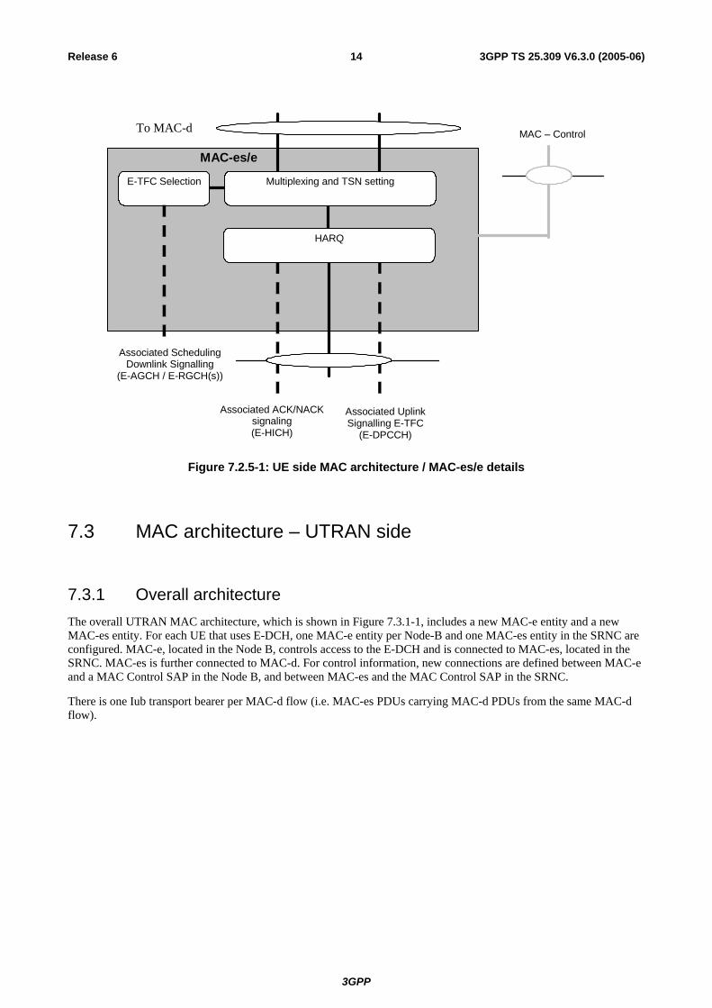
7.2.5 Details of MAC-es/MAC-e The MAC-es/e handles the E-DCH specific functions. The split between MAC-e and MAC-es in the UE is not detailed. In the model below the MAC-e/es comprises the following entities:
- HARQ: The HARQ entity is responsible for handling the MAC functions relating to the HARQ protocol. It is responsible for storing MAC-e payloads and re-transmitting them. The detailed configuration of the hybrid ARQ protocol is provided by RRC over the MAC-Control SAP. The HARQ entity provides the E-TFC, the retransmission sequence number (RSN), and the power offset to be used by L1. Redundancy version (RV) of the HARQ transmission is derived by L1 from RSN, CFN and in case of 2 ms TTI from the sub-frame number. RRC signalling can also configure the HARQ entity to use RV=0 for every transmission.
- Multiplexing: The multiplexing entity is responsible for concatenating multiple MAC-d PDUs into MAC-es PDUs, and to multiplex one or multiple MAC-es PDUs into a single MAC-e PDU, to be transmitted at the next TTI, and as instructed by the E-TFC selection function. It is also responsible for managing and setting the TSN per logical channel for each MAC-es PDU.
- E-TFC selection: This entity is responsible for E-TFC selection according to the scheduling information (Relative Grants and Absolute Grants) received from UTRAN via L1, and for arbitration among the different flows mapped on the E-DCH. The detailed configuration of the E-TFC entity is provided by RRC over the MAC-Control SAP. The E-TFC selection function controls the multiplexing function.
3GPP
3GPP TS 25.309 V6.3.0 (2005-06)14Release 6
MAC-es/e
MAC – Control
Associated Uplink Signalling E-TFC
(E-DPCCH)
To MAC-d
HARQ
Multiplexing and TSN setting E-TFC Selection
Associated Scheduling Downlink Signalling
(E-AGCH / E-RGCH(s))
Associated ACK/NACKsignaling (E-HICH)
Figure 7.2.5-1: UE side MAC architecture / MAC-es/e details
7.3 MAC architecture – UTRAN side
7.3.1 Overall architecture The overall UTRAN MAC architecture, which is shown in Figure 7.3.1-1, includes a new MAC-e entity and a new MAC-es entity. For each UE that uses E-DCH, one MAC-e entity per Node-B and one MAC-es entity in the SRNC are configured. MAC-e, located in the Node B, controls access to the E-DCH and is connected to MAC-es, located in the SRNC. MAC-es is further connected to MAC-d. For control information, new connections are defined between MAC-e and a MAC Control SAP in the Node B, and between MAC-es and the MAC Control SAP in the SRNC.
There is one Iub transport bearer per MAC-d flow (i.e. MAC-es PDUs carrying MAC-d PDUs from the same MAC-d flow).

3GPP
3GPP TS 25.309 V6.3.0 (2005-06)15Release 6
FACH RACH
DCCH DTCH DTCH
DSCH
MAC Control
Iur or local
MAC Control
DCH DCH
MAC-d
USCH TDD only
MAC-c/sh
CPCH FDD only
CCCH CTCH BCCH SHCCH TDD only
PCCH
FACH PCH USCH TDD only
DSCH
MAC Control
HS- DSCH HS- DSCH
Associated Uplink Signalling
Associated Downlink Signalling
MAC-hs
Configuration without MAC-c/sh
Configurationwith MAC
Configuration with MAC-c/sh
E- DCH
Associated Uplink Signalling
Associated Downlink Signalling
MAC Control
MAC-es
MAC-e
MAC Control
Iub
c/sh
Figure 7.3.1-1: UTRAN side MAC architecture (SHO not shown)
As shown in Figure 7.3.1-2, a MAC-e PDU enters MAC from layer 1. After Hybrid ARQ handling, the MAC-e PDU is demultiplexed to form MAC-es PDUs aimed for one or more MAC-d flows. The mapping between the DDI (Data Description Indicator) fields (6 bits) and the MAC-d flow and MAC-d PDU size is provided to the Node B by the SRNC. The mapping of the MAC-d flow into its Iub bearer is defined by the SRNC. A special value of the DDI field indicates that no more data is contained in the remaining part of the MAC-e PDU. The MAC-es PDUs are sent over Iub to MAC-es, where they are distributed on the reordering queue of each logical channel. After re-ordering, the in-sequence data units are disassembled. The resulting MAC-d PDUs are forwarded to MAC-d and RLC.

3GPP
3GPP TS 25.309 V6.3.0 (2005-06)16Release 6
Mac-es PDU:
Reordering queue distribution
Reordering queue distribution
DCCH DTCH DTCH
MAC-d Flows
HARQ
Demultiplexing
DATA Header
MAC-d
MAC-e
DATA
DATA
DATA DATA
MAC-e PDU:
RLC PDU:
L1
RLC
Reordering
MAC-es
Reordering Reordering
Disassembly Disassembly Disassembly
MAC-d PDU:
Mapping info signaled to Node B DDI => MAC-d PDU size, MAC-d flow ID
TSN
MAC-e header
DDI N Padding (Opt)
DDI N DATA DATA DDI
Transport block:
DDI N Iub FP:
Figure 7.3.1-2: Simplified architecture showing MAC inter-working in UTRAN. The left part shows the functional split while the right part shows PDU decomposition.
7.3.2 Details of MAC-d For support of E-DCH a new connection to MAC-es is added.

3GPP
3GPP TS 25.309 V6.3.0 (2005-06)17Release 6
DCCH
DTCH DTCH
DCH DCH
MAC-d to MAC-c/sh
MAC-Control
C/T MUX
DL scheduling/ priority handling
Ciphering
Transport Channel Type Switching
Deciphering
to MAC-hs
from MAC-es
Flow Control
C/T MUX / Priority
setting (DL)
Figure 7.3.2-1: UTRAN side MAC architecture / MAC-d details
7.3.3 Details of MAC-c/sh The support of E-DCH implies no change to the UTRAN MAC-c/sh entity
7.3.4 Details of MAC-hs The support of E-DCH implies no change to the UTRAN MAC-hs entity
7.3.5 Details of MAC-es For each UE, there is one MAC-es entity in the SRNC. The MAC-es sublayer handles E-DCH specific functionality, which is not covered in the MAC-e entity in Node B. In the model below, the MAC-es comprises the following entities:
- Reordering Queue Distribution: The reordering queue distribution function routes the MAC-es PDUs to the correct reordering buffer based the SRNC configuration.
- Reordering: This function reorders received MAC-es PDUs according to the received TSN and Node-B tagging i.e. (CFN, subframe number). MAC-es PDUs with consecutive TSNs are delivered to the disassembly function upon reception. PDUs are not delivered to the disassembly function if PDUs with a lower TSN are missing. The number of reordering entities is controlled by the SRNC. There is one Reordering Queue per logical channel.
- Macro diversity selection: The function is performed in the MAC-es, in case of soft handover with multiple Node-Bs (The soft combining for all the cells of a Node-B takes place in the Node-B). This means that the reordering function receives MAC-es PDUs from each Node-B in the E-DCH active set. The exact implementation is not specified. However the model below is based on one Reordering Queue Distribution entity receiving all the MAC-d flow from all the Node-Bs, and one MAC-es entity per UE.
- Disassembly:
The disassembly function is responsible for disassembly of MAC-es PDUs. When a MAC-es PDU is disassembled the MAC-es header is removed, the MAC-d PDU’s are extracted and delivered to MAC-d.

3GPP
3GPP TS 25.309 V6.3.0 (2005-06)18Release 6
MAC-es
MAC – Control
From MAC-e in NodeB #1
To MAC-d
Disassembly
Reordering Queue Distribution
Reordering Queue Distribution
Disassembly
Reordering/
Combining
Disassembly
Reordering/ Combining
Reordering/ Combining
From MAC-e in NodeB #k
MAC-d flow #1 MAC-d flow #n
Figure 7.3.5-1: UTRAN side MAC architecture / MAC-es details (SHO case)
7.3.6 Details of MAC-e There is one MAC-e entity in Node B for each UE and one E-DCH scheduler function in the Node-B. The MAC-e and E-DCH scheduler handle HSUPA specific functions in Node B. In the model below, the MAC-e and E-DCH scheduler comprises the following entities:
- E-DCH Scheduling : This function manages E-DCH cell resources between UEs. Based on scheduling requests, scheduling assignments are determined and transmitted. The general principles of the E-DCH scheduling are described in subclause 9.1 below. However implementation is not specified (i.e. depends on RRM strategy).
- E-DCH Control : The E-DCH control entity is responsible for reception of scheduling requests and transmission of scheduling assignments. The general principles of the E-DCH scheduling are described in subclause 9.1 below.
- De-multiplexing: This function provides de-multiplexing of MAC-e PDUs. MAC-es PDUs are forwarded to the associated MAC-d flow.
- HARQ: One HARQ entity is capable of supporting multiple instances (HARQ process) of stop and wait HARQ protocols. Each process is responsible for generating ACKs or NACKs indicating delivery status of E-DCH transmissions. The HARQ entity handles all tasks that are required for the HARQ protocol.
The associated signalling shown in the figure illustrates the exchange of information between layer 1 and layer 2 provided by primitives.

3GPP
3GPP TS 25.309 V6.3.0 (2005-06)19Release 6
MAC-e
MAC – Control
E-DCH Associated Downlink Signalling
Associated Uplink
Signalling
MAC-d Flows
De-multiplexing
HARQ entity
E-DCH
Control (FFS)
E-DCH Scheduling (FFS)
Figure 7.3.6-1: UTRAN side MAC architecture / MAC-e details
8 HARQ protocol
8.1 General Principle The HARQ protocol has the following characteristics:
- Stop and wait HARQ is used;
- The HARQ is based on synchronous downlink ACK/NACKs;
- The HARQ is based on synchronous retransmissions in the uplink:
- The number of processes depends on the TTI: 8 processes for the 2ms TTI and 4 processes for the 10ms TTI. For both scheduled and non-scheduled transmission for a given UE, it is possible to restrict the transmission to specific processes for the 2ms E-DCH TTI;
- There will be an upper limit to the number of retransmissions. The UE decides on a maximum number of transmissions for a MAC-e PDU based on the maximum number of transmissions attribute (see subclause 11.1.1), according to the following principles:
- The UE selects highest maximum number of transmissions among all the considered HARQ profiles associated to the MAC-d flows in the MAC-e PDU;
- Further optimisations such as explicit rules set by the SRNC are FFS.
- Pre-emption will not be supported by E-DCH;
- In case of TTI reconfiguration, the MAC-e HARQ processes are flushed and no special mechanism is defined to lower SDU losses.
- Intra Node B macro-diversity and Inter Node B macro-diversity should be supported for the E-DCH with HARQ;
- Incremental redundancy shall be supported by the specifications with Chase combining as a subcase:

3GPP
3GPP TS 25.309 V6.3.0 (2005-06)20Release 6
- The first transmission shall be self decodable;
- The UTRAN configures the UE to either use the same incremental redundancy version (RV) for all transmissions, or to set the RV according to set of rules based on E-TF, Retransmission Sequence Number (RSN) and the transmission timing;
- There shall be no need, from the H-ARQ operation point of view, to reconfigure the Node B from upper layers when moving in or out soft handover situations. However, the Node-B may be aware of the soft handover status via a soft handover indicator.
8.2 Error handling The most frequent error cases to be handled are the following:
- NACK is detected as an ACK: the UE starts afresh with new data in the HARQ process. The previously transmitted data block is discarded in the UE and lost. Retransmission is left up to higher layers;
- ACK is detected as a NACK: if the UE retransmits the data block, the NW will re-send an ACK to the UE. If in this case the transmitter at the UE sends the RSN set to zero, the receiver at the NW will continue to process the data block as in the normal case;
- Error cases have been identified regarding the HARQ operation during soft handover:
- In case the HARQ control information transmitted on the E-DPCCH could not be detected RSN_max times in a row for one HARQ process, a soft buffer corruption might occur. Each HARQ process uses RSN and the transmission time (CFN, sub-frame) elapsed since storing data in the associated soft buffer in order to flush the soft buffer and to avoid a wrong combining of data blocks.
- Duplication of data blocks may occur at the RNC during soft handover. The reordering protocol needs to handle the detected duplications of data blocks.
8.3 Signalling
8.3.1 Uplink
8.3.2 Downlink In the downlink, a report is used to indicate either ACK (positive acknowledgement) or NACK (negative acknowledgement).
9 Node B controlled scheduling
9.1 General Principle The Node B controlled scheduling is based on uplink and downlink control together with a set of rules on how the UE shall behave with respect to this signaling.
In the downlink, a resource indication (Scheduling Grant) is required to indicate to the UE the maximum amount of uplink resources it may use. When issuing Scheduling Grants, the Node B may use QoS-related information provided by the SRNC (see subclause 11.1.1) and from the UE in Scheduling Requests (see subclause 9.3.1)
The Scheduling Grants have the following characteristics:
- Scheduling Grants are only to be used for the E-DCH TFC selection algorithm (i.e. they do not to influence the TFC selection for the DCHs);
- Scheduling Grants control the maximum allowed E-DPDCH/DPCCH power ratio of the active processes. For the inactive processes, the power ratio is 0 and the UE is not allowed to transmit;

3GPP
3GPP TS 25.309 V6.3.0 (2005-06)21Release 6
- All grants are deterministic;
- Scheduling Grants can be sent once per TTI or slower;
- There are two types of grants:
- The Absolute Grants provide an absolute limitation of the maximum amount of UL resources the UE may use;
- The Relative Grants increase or decrease the resource limitation compared to the previously used value;
- Absolute Grants are sent by the Serving E-DCH cell:
- They are valid for one UE, for a group of UEs or for all UEs;
- The Absolute Grant contains:
- the identity (E-RNTI) of the UE (or group of UEs) for which the grant is intended;
- the maximum power ratio the UE is allowed to use, on 5 bits;
- in case of 2ms TTI an HARQ process activation flag indicating if the Primary Absolute Grant activates or deactivates one or all HARQ processes. That bit is also used to switch the UE from its primary E-RNTI to its secondary E-RNTI for both the 2ms and the 10ms TTI. The use of the bit encoding the flag is FFS for the Secondary Absolute Grant.
- Group identities or dedicated identities are not distinguished by the UE. It is up to the UTRAN to allocate the same identity to a group of UEs;
- Up to two identities (E-RNTIs) , one primary and one secondary, can be allocated to a UE at a time. In that case, both identities shall use the same E-AGCH channel. The allocation is done by the Node-B and sent by the SRNC in RRC.
- The identity consists of 16 bits (16 bits CRC at layer 1);
- Relative Grants (updates) are sent by the Serving and Non-Serving Node-Bs as a complement to Absolute Grants:
- The UE behaviour is exactly the same for Relative Grants for one UE, for a group of UEs and for all UEs;
- The Relative Grant from the Serving E-DCH RLS can take one of the three values: “UP”, “HOLD” or “DOWN”;
- The Relative Grant from the Non-serving E-DCH RL can take one of the two values: “HOLD” or “DOWN”. The “HOLD” command is sent as DTX. The “DOWN” command corresponds to an “overload indicator”;
- For each UE, the non-serving Node-B operation is as follows:
- If the Node-B could not decode the E-DPCCH/E-DPDCH for the last n1 TTIs (where n1 is TBD) because of processing issue, it shall notify the SRNC;
- The non-serving Node-B is allowed to send a “DOWN” command only for RoT reasons (maximum allocated uplink RoT in the cell is exceeded) and not because of lack of internal processing resources.
9.2 UE scheduling operation
9.2.1 Grants from the Serving RLS The UE shall be able to receive Absolute Grant from the Serving E-DCH cell and Relative Grant from the Serving E-DCH RLS.
The UE shall handle the Grant from the Serving E-DCH RLS as follows:
- The UE maintains a “Serving Grant” (SG);

3GPP
3GPP TS 25.309 V6.3.0 (2005-06)22Release 6
- The SG is used in the E-TFC selection algorithm as the maximum allowed E-DPDCH/DPCCH power ratio for the transmission of the active HARQ processes;
- The SG is updated according to the following algorithm, regardless of the transmission/retransmission status of the HARQ process. The SG is not used for the E-TFC selection algorithm if the HARQ process is in retransmission;
- Each Absolute Grant and Relative Grant is associated with a specific uplink E-DCH TTI i.e. HARQ process. This association is implicit based on the timing of the E-AGCH and E-RGCH (see [3]). The timing is tight enough that this relationship is un-ambiguous;
- When receiving an “Absolute Grant” on the E-AGCH of the serving E-DCH cell:
- Primary Absolute Grants always affect the SG;
- Secondary Absolute Grants only affect the SG if the last Primary Absolute Grant was set to ‘INACTIVE’ and the process activation flag was set to ‘All’ (transition trigger), or if the latest Absolute Grant that affected the SG was the Secondary one. When the transition to the secondary E-RNTI is triggered, UE shall update the SG with the latest received Absolute Grant on the secondary E-RNTI (UE must listen to both E-RNTIs in parallel);
- In case of 10ms TTI, SGi is set to the received value;
- In case of 2ms TTI and a Primary Absolute Grant was received:
- If the received value is different from ‘INACTIVE’, the SG is set to that value and the following activation mechanism is applied to processes that are not disabled as per L3 signalling:
- In case of an AG associated to an inactive process, the process activation flag indicates whether all processes or only this particular process becomes active;
- In case of an AG associated to an active process, the process activation flag will indicate whether all processes become active (‘all’) or the activation status of the processes is not changed (‘single’);
- If the received value is ‘INACTIVE’, the UE behaviour depends on the process activation flag:
- If the flag is set to ‘single’, only one active process becomes inactive;
- If the activation flag is set to ‘All’ and the secondary E-RNTI is configured:
- All L3-enabled processes that are deactivated become active.
- If the activation flag is set to ‘All’ and the secondary E-RNTI is not configured:
- All L3-enabled processes are deactivated (if a process was inactive it remains inactive, if a process was active it becomes inactive).
- In case of 2ms TTI and a Secondary Absolute Grant was received:
- In case the Secondary Absolute Grant affects the SG, the SG is set to the received value.
- If no “Absolute Grant” is received by the UE in a TTI and the last SG update was due to a Primary Absolute Grant, then the UE shall follow the “Relative Grant” of the Serving E-DCH RLS:
- A Serving Relative Grant is interpreted relative to the UE power ratio in the previous TTI for the same hybrid ARQ process as the transmission which the Relative Grant will affect (see figure 9.2.1-1);

3GPP
3GPP TS 25.309 V6.3.0 (2005-06)23Release 6
1 2 3 4 1 2 3
E-RGCH
E-DCH
HARQ process number
Scheduling decision
Load estimation, etc
RG interpreted relative to the previous TTI in this HARQ process.
Figure 9.2.1-1: Timing relation for Relative Grant
- When the UE receives an “UP” from Serving E-DCH RLS:
- New SG = Last used power ratio + Delta;
- When the UE receives a “DOWN” from Serving E-DCH RLS:
- New SG = Last used power ratio – Delta;
- The reference Delta is configured via RRC. Whether or not different values can be signalled for ‘UP’ and ‘DOWN’ is FFS. Whether the applied Delta is data rate dependent or not is FFS;
- When the UE receives a “HOLD” (i.e. DTX) from the Serving E-DCH RLS:
- SG remains unchanged.
9.2.2 Grants from the Non-serving RL Non-serving RLs will only send Relative Grants to the UE. The UE shall handle the RG from these non-serving E-DCH RLs as follows:
- When the UE receives a “DOWN” from at least one Non-serving E-DCH RL, it is interpreted relative to the UE power ratio in the previous TTI for the same hybrid ARQ process as the transmission which the Relative Grant will affect (see figure 9.2.1-1):
New SG = Last used power ratio – Delta;
- The Delta is configured via RRC;
- The option to use a calculated offset is FFS (e.g. the offset may be function of the measured CPICH power on the overloaded cells in relation to the measured CPICH power on the serving cell);
- When the UE does not receive a “DOWN” from any Non-serving E-DCH RL;
- The UE shall follow the Serving E-DCH RLS’s Scheduling Grants.
9.2.3 Reception of Grants from both the Serving RLS and Non-serving RL In the case of a UE receiving grants from both the Serving RLS and Non-Serving RL(s), the UE behaviour is the following:
- When the UE receives a scheduling grant from the Serving E-DCH RLS and a "DOWN" command from at least one Non-Serving E-DCH RL:
- new SG is set to the minimum between the Last used power ratio minus Delta and the received AG/RG from serving RLS.
3GPP
3GPP TS 25.309 V6.3.0 (2005-06)24Release 6
9.3 Signalling
9.3.1 Uplink For the UE to request resources from the Node B(s), Scheduling Requests will be transmitted in the uplink in the form of Scheduling Information and Happy Bit. The Scheduling information will be transmitted for the logical channels for which RRC configured that reporting needs to be made, while the Happy Bit shall be transmitted on the E-DPCCH always.
9.3.1.1 Scheduling Information
9.3.1.1.1 Content
The UE includes the following in the Scheduling Information (only taking into account the logical channels for which RRC configured that reporting was required and always excluding logical channels mapped on non-scheduled MAC-d flows):
- Logical channel ID of the highest priority channel with data in buffer, on 4 bits. The logical channel ID field identifies unambigiouly the highest priority logical channel with available data and QoS information related to this indicated logical channel;
- UE Buffer occupancy (in Bytes):
- Buffer status for the highest priority logical channel with data in buffer, on 4 bits, as a fraction of the total reported buffer;
- Total buffer status, on 5 bits;
- Estimation of the available power ratio versus DPCCH (taking into account HS-DPCCH), on 5 bits (or less, depending on RAN4 results). UE shall not take DPDCH power into account when performing the estimation. Whether the backoff is taken into account or not is FFS.
9.3.1.1.2 Triggers
In the case where the UE has no Serving Grant available and it has Scheduled data to send on a logical channel for which Scheduling Information must be reported:
- Scheduling Information shall be sent to the Serving E-DCH RLS in a MAC-e PDU;
- Periodic reporting to protect against NACK-to-ACK misinterpretation;
- Scheduling Information could be sent alone, or with non-scheduled data, if such exist.
In the case where the UE has a Serving Grant available:
- it shall send the Scheduling Information to the Serving E-DCH RLS in the MAC-e PDU;
- the Scheduling Information is sent periodically (period defined by RRC);
- use of events to trigger Scheduling Information is FFS.
The details on how Scheduling Information is included in the MAC-e PDU are FFS.
9.3.1.1.3 Transmission and Reliability scheme
Two transmission mechanisms are defined, depending on whether the Scheduling Information is transmitted alone, or with data (scheduled and/or non-scheduled):
1. When the Scheduling Information is sent alone:
- The power offset is configured by RRC and the maximum number of re-transmissions is defined by the standard;

3GPP
3GPP TS 25.309 V6.3.0 (2005-06)25Release 6
- HARQ (re)transmissions are performed until an ACK from the RLS containing the serving cell is received or until the max number of transmissions is reached.
2. When Scheduling Information is sent with data:
- Use the HARQ power offset attribute of the highest priority data, and the maximum number of transmissions among all the considered HARQ profiles associated to the MAC-d flows for the MAC-e PDU to be transmitted;
- HARQ (re)transmissions are performed until an ACK is received, or until the max number of transmissions is reached.
- If the UE receives an ACK from an RLS not containing the serving cell for a packet that includes scheduling information, it flushes the packet and includes the scheduling information with new data payload in the following packet.
9.3.1.2 Happy bit of E-DPCCH
One bit of the E-DPCCH is used to indicate whether or not the UE is satisfied (‘happy’) with the current Serving Grant. This bit shall always be present during uplink transmission.
The UE shall indicate that it is ‘unhappy’ if both of the following criteria are met:
1) UE has Power available to send at higher data rates (E-TFCs) (link to E-TFC selection/elimination over recent past is FFS, filtering is FFS), and
2) Total buffer status would require more than X TTIs with the current Grants (where X is configurable). Details are FFS.
Otherwise, the UE shall indicate that it is ‘happy’.
9.3.2 Downlink For each UE, there is only one Absolute Grant transmitted by the serving E-DCH cell using the E-AGCH.
For each UE, there is one Relative Grant transmitted per Serving RLS and Non-serving RL from the E-DCH active set cells. The channel(s) (one per cell) on which the Relative Grant is transmitted is(are) signalled separately to each UE (this allows for the same channel to be monitored by multiple UEs if it is UTRAN decision).
10 Non-scheduled transmissions When non-scheduled transmission is configured by the SRNC, the UE is allowed to send E-DCH data at any time, up to a configured number of bits, without receiving any scheduling command from the Node B. Thus, signalling overhead and scheduling delay are minimized.
Typical examples of data that may use non-scheduled transmission are the SRBs and GBR services.
Non-scheduled transmissions have the following characteristics:
- Non-scheduled transmissions are defined per MAC-d flow;
- The resource for non-scheduled transmission is given by the SRNC in terms of maximum number of bits that can be included in a MAC-e PDU, and is called non-scheduled grant;
- Scheduled logical channels cannot use the non-scheduled grant.
- UTRAN can restrict a non-scheduled MAC-d flow to use a limited number of HARQ processes in case of 2ms TTI. The same restriction for the 10ms TTI is FFS;

3GPP
3GPP TS 25.309 V6.3.0 (2005-06)26Release 6
- UTRAN can reserve some HARQ processes for non-scheduled transmission (i.e. scheduled data cannot be sent using these processes, they are considered disabled) in case of 2ms TTI. The same reservation scheme for the 10ms TTI is FFS;
- Multiple non-scheduled MAC-d flows may be configured in parallel by the SRNC;
- The UE is then allowed to transmit non-scheduled transmissions up to the sum of the non-scheduled grant if multiplexed in the same TTI;
- Scheduled grants will be considered on top of non-scheduled transmissions;
- Logical channels mapped on a non-scheduled MAC-d flow cannot transmit data using a Scheduling Grant;
- Logical channels mapped on a non-scheduled MAC-d flow can only transmit up to the non-scheduled grant configured for that MAC-d flow;
- The multiplexing list restricting the set of HARQ profiles that can be used by a given logical channel will apply both for scheduled and non-scheduled logical channels;
- Logical channels will be served in the order of their priorities until the non-scheduled grant and scheduled grants are exhaused, or the maximum transmit power is reached;
- When multiple logical channels are assigned the highest priority, the selection of the HARQ profile for these logical channels is not specified.
11 QoS control
11.1 General Principle The QoS of ongoing flows mapped on E-DCH for a UE is maintained by the serving Node B and by the UE. The Node B controls the resources allocated to a UE versus other UEs by means of scheduling as specified in clause 9. The UE controls the QoS of all its logical channels mapped on E-DCH by means of E-TFC selection as specified in subclause 11.2, and by HARQ operation, specified in clause 8.
In addition to these mechanisms, guaranteed bit rate services for MAC-d flows are also supported through non-scheduled transmission. A flow using non-scheduled transmission is defined by the SRNC and provided in the UE and in the Node B. Details on non-scheduled transmission can be found in section 10.
11.1.1 QoS configuration principles RAB attributes are available in the SRNC according to R'99 principles. To enable QoS control for the E-DCH, QoS-related information is made available in the UE and in the Node B as outlined below.
To the UE, the following QoS-related information is provided from the SRNC to enable QoS-based E-TFC selection, multiplexing of logical channels in MAC-e PDUs, and HARQ operation:
- Logical channel priority for each logical channel (as in Rel-5);
- Mapping between logical channel(s) and MAC-d flow(s) (as in Rel-5);
- Allowed MAC-d flow combinations in one MAC-e PDU;
- Power offset for reference E-TFC(s). The UE then calculates the power offsets for its other E-TFCs so that the quality (protection of a MAC-e PDU) when using any of the E-TFCs is identical to that of the reference E-TFC(s);
- The E-DPCCH power offset. This is used to set the protection level for E-DPCCH transmissions;
- HARQ profile per MAC-d flow. One HARQ profile consists of a power offset attribute and a maximum number of transmissions attribute. The power offset attribute is used in E-TFC selection to regulate the

3GPP
3GPP TS 25.309 V6.3.0 (2005-06)27Release 6
BLER operating point for the transmission. The maximum number of transmissions attribute is used in the HARQ operation to regulate maximal latency and residual BLER of MAC-d flows.
- The non-scheduled grant (only for MAC-d flows that are configured for non-scheduled transmission).
To the Node Bs in the E-DCH active set, the following QoS-related parameters are provided by the SRNC to enable scheduling and resource reservation:
- Power offsets for reference E-TFC(s). The Node B then calculates the power offsets for the other E-TFCs. This information is used whenever the nodeB needs to convert between rate and power in its resource allocation operation;
- E-DPCCH power offset; This is used whenever the Node B needs to convert between rate and power in its resource allocation operation;
- HARQ profile per MAC-d flow. One HARQ profile consists of a power offset attribute and a maximum number of transmissions attribute. The power offset attribute is used whenever the Node B needs to convert between rate and power in its resource allocation operation;
- Guaranteed bit rate for logical channels that carry guaranteed bit rate services. It is used to allocate grants to UEs;
- The non-scheduled grant for MAC-d flows that are configured for non-scheduled transmission. It is used for the Node B to reserve sufficient amount of resources. The need for additional mechanisms to optimize the Node-B hardware is FFS (e.g. the UE may tell the Node-B ahead that an non-scheduled transmission is coming);
- Maximum UL UE power, as a minimum of the UE maximum transmit power (as per UE power class) and maximum allowed UL Tx power configured by UTRAN. This information is only sent to the serving cell’s nodeB (whether the max UL UE power can also be signalled to other nodeBs in the active set or not is FFS);
- Scheduling priority per logical channel of logical channels mapped to E-DCH and the corresponding mapping between logical channel identifier and DDI value. This information enables Node B to consider QoS related information of the logical channels for efficient scheduling.
11.2 TFC and E-TFC selection Logical channels mapped on the DCHs are always prioritised over those mapped on E-DCHs.
The principle of the TFC selection across E-DCH and DCH is the following:
- The UE performs TFC restriction for the CCTrCH of DCH type;
- The UE performs the TFC selection for the DCHs;
- E-TFC restriction is performed with the following characteristics;
- The E-TFC restriction mechanism is independent of the existing TFC restriction;
- The E-TFC states defined per MAC-d flow are managed independently of the TFC states;
- The UE uses the power offsets for the reference E-TFC(s), the signalled power offset attributes for its MAC-d flows, the required E-TFC dependent backoff, and the UE remaining power to determine the E-TFC states;
- The HS-DPCCH, DPCCH, DPDCH and E-DPCCH powers are taken into account when calculating the remaining power;
- The result of E-TFC restriction is a state (blocked or supported) per E-TFC and MAC-d flow;
- The minimum set of E-TFCs is defined as the number of bits that can be transmitted in a TTI independent of the power situation in the UE, provided there is nothing sent on the DCH, and is configurable from the RNC as one E-TFC per UE. When there is nothing sent on DCH, the E-TFCs belonging to the minimum set are in supported state;
3GPP
3GPP TS 25.309 V6.3.0 (2005-06)28Release 6
- In the case where 2ms TTI is configured, E-TFC selection shall not be performed for TTIs that overlap with an uplink compressed mode gap;
- Then the UE performs the E- TFC selection for the E-DCH, taking into account the following rules:
- The E-TFC selection is based on logical channel priorities like in the Release '99, i.e. the UE shall maximise the transmission of higher priority data;
- The UE shall respect the allowed combinations of MAC-d flows in the same MAC-e PDU;
- The UE shall use the multiplexing list of the different MAC-d flows to see if a certain MAC-d flow can use the power offset of the highest priority MAC-d flow to be transmitted;
- The supported/blocked E-TFCs for a MAC-e PDU including MAC-d PDUs coming from one or several MAC-d flows are obtained as follows:
- The UE uses the E-TFC restriction result (i.e. blocked/supported E-TFCs) associated to the MAC-d flow with the highest priority logical channel in the MAC-e PDU;
- For a 10ms TTI E-DPDCH frames that overlaps with compressed mode gaps, the Serving Grant shall be scaled back according to the procedure described in [3];
- Among the supported E-TFCs, the UE selects the smallest E-TFC that maximises the transmission of data according to the non-scheduled grant(s) and the serving grant;
- For each transmission, the MAC-e entity gives the selected power offset of E-DPDCH(s) relative to DPCCH to the L1 in addition to the E-TFC;
- In case the maximum UE transmit power is exceeded, the UE shall scale down the E-DPDCH only on TTI level for retransmissions. At slot level all uplink physical channels are equally compressed. The scaling down of only E-DPDCH at slot level remains FFS.
- In case the selected E-TFC leads to a case where the maximum UE transmit power is exceeded because the selected E-TFC is part of the minimum set, the UE shall power scale down all physical channels present.
11.3 Setting of Power offset attributes of MAC-d flows Power offset attributes of MAC-d flows are part of the HARQ profiles of the MAC-d flow. They are provided by the UTRAN to the UE according to the following principles:
- The DPCCH transmission power is controlled the same way as in Release '99;
- In case where there is no need for a DCH (i.e. the SRBs are mapped on the E-DCH), a size 0 TrBlck may be required (FFS);
- With each MAC-es PDU transmitted to the SRNC, the Node-B includes the number of transmissions that have been required to correctly decode the PDU;
- Using the information provided by the Node B, the SRNC may maintain up to date power offsets;
- The SRNC may decide to signal to the UE and the node Bs in the E-DCH active set new values for the power offset attributes for one (or several) MAC-d flows.
- No other power management/control mechanism is needed for E-DCH.
12 Signalling parameters
12.1 Uplink signalling parameters Void.

3GPP
3GPP TS 25.309 V6.3.0 (2005-06)29Release 6
12.2 Downlink signalling parameters With RRC signalling, the UE will in addition be informed about:
- The E-HICH configuration
- Including signature sequence number and channelisation code;
- The E-RGCH configuration
- Including signature sequence number, channelisation code, RG reference step size for serving RLS and RG step size for non-serving RL and Serving E-DCH RLS ID;
- The E-AGCH configuration
- Including E-RNTI(s) and channelisation code;
- The E-DPCCH configuration
- Including E-DPCCH/DPCCH Power Offset;
- The E-DPDCH configuration:
- A UE is allocated one and only one TB size table by RRC. A total of four TB size tables are defined by the standard:
- Exponentially distributed TB sizes over the corresponding dynamic range, one optimized table for 2ms TTI and one optimized table for 10ms TTI;
- TB sizes for 336 bit RLC PDU size, one optimized table for 2ms TTI and one optimized table for 10ms TTI;
- For each reference E-TFC a (nominal) beta factor is calculated based on the power offset signalled for each reference E-TFC via RRC (number of reference E-TFCs is FFS);
- A minimum set of E-TFCs, which is the largest E-TFC that can be used by the UE independent of the UE power situation, given that a valid grant is available and there is no transmission on DCH;
- HARQ Incemental Redundancy Version configuration. Always use RV=0 or use the RV table;
- Maximum number of E-DPDCH channelisation code;
- Minimum SF;
- PLnon-max (Puncturing Limit used to determine the combination of SF and the number of codes that are used for transmitting E-DCH with a certain data rate);
- Processes in which transmission of a MAC-d flow using non-scheduled data is allowed for the 2ms E-DCH TTI;
- Processes in which transmission of scheduled data is allowed (L3-enabled processes) for the 2ms E-DCH TTI;
- E-DCH Scheduling Information parameters:
- Logical channels for which Scheduling Information is expected to be reported by the UE;
- Logical channel identity of logical channels mapped to E-DCH;
- Period for sending Scheduling Information (applicable when no Scheduling Grant has been received);
- Period for sending Scheduling Information (applicable once a Scheduling Grant has been received) ;
- Power offset to use when sending Scheduling Information alone;

3GPP
3GPP TS 25.309 V6.3.0 (2005-06)30Release 6
- Threshold (in TTIs) used by the UE when evaluating the time needed to completely empty its buffers. Used as a conditions for setting the ‘happy’ bit in E_DPCCH.
RRC will signal the mapping between logical channel, MAC-d PDU size, MAC-d flow ID and Data Description Indicator (see clause 7).
RRC will signal for each MACd-flow, the MAC-d flow specific power offset, the maximum number of transmissions, and the multiplexing list (indicating with which other MAC-d flows, MAC-d PDU’s of this flow can be multiplexed in the same MAC-e PDU).
13 Mobility procedures
13.1 Change of serving cell and/or serving RLS Change of serving cell and/or change of serving RLS for E-DCH scheduling is supported via RRC signalling.
UTRAN may:
- For the serving RLS, select the RLS with the highest data throughput;
- For the serving cell, select that cell out of the serving RLS, which provides the best downlink quality.
UE based change of serving cell and/or change of serving RLS or mechanisms using L2 signalling are not supported for E-DCH mobility.
When an E-DCH serving cell change is trigerred:
- The E-RNTI (primary or secondary) the UE will initially use to update its SG is given by RRC;
- Processes can be enabled/disabled via RRC;
- The new SG is signaled through RRC;
- All L2-deactivated processes become active;
14 Resource Management
14.1 Scheduler control from CRNC to Node B The CRNC may send a maximum total RTWP value to the Node B to control cell coverage. The value reflects total interference including contributions from all uplink traffic and external interferers. The scheduler can use this value when issuing grants. The result of the scheduling shall be such that the maximum total RTWP value is not exceeded.
The CRNC may send the target value of Non-serving E-DCH to serving E-DCH power ratio per cell to the Node-B. Node-B should not send Non-serving RL RG “Down” command, unless both of the following criteria are met:
1. Experienced total RTWP > Target RTWP signalled from CRNC
2. Non-serving E-DCH to serving E-DCH power ratio > Target ratio signalled from CRNC
Non-serving E-DCH to serving E-DCH power ratio is the ratio of non-serving RL E-DCH power and serving RLS E-DCH power received at the NodeB. Received non-serving E-DCH power and serving E-DCH power may be calculated from the E-TFC information on the E-DPCCH and a reference power offset. A reference power offset is defined per UE and signalled from CRNC to Node-B for this calculation.

3GPP
3GPP TS 25.309 V6.3.0 (2005-06)31Release 6
14.2 Node B to CRNC reporting Radio Access Bearers with strict quality requirements (mapped on E-DCH or DCH) are subject to admission control. To support such admission control and to enable noise floor estimation, the Node B shall measure/estimate and signal to the CRNC the following:
- Total RTWP (as in Rel-5);
- Provided bit rate per logical channel priority per cell, taking into account only logical channels mapped on E-DCH.
To enable the CRNC to manage resources between cells, a load excess indicator shall be signalled from Node-B to CRNC if the frequency of the “Down” commands towards UEs other cells of the active set becomes more than a pre-defined level. The detailed conditions under which this load excess indicator should be sent are FFS.

3GPP
3GPP TS 25.309 V6.3.0 (2005-06)32Release 6

3GPP
3GPP TS 25.309 V6.3.0 (2005-06)33Release 6
Annex A (informative): Change history
Change history Date TSG # TSG Doc. CR Rev Subject/Comment Old New 09/2004 RP-25 RP-040358 - Approved at TSG-RAN #25 and placed under Change Control. 1.0.0 6.0.0 12/2004 RP-26 RP-040486 001 3 Inclusion of e.g. physical layer model, MAC architecture, detail
Node B scheduler mechanism and QoS Control principles 6.0.0 6.1.0
RP-26 RP-040487 002 2 Scheduling Grants as E-DPDCH/DPCCH power ratio 6.0.0 6.1.0 RP-26 RP-040486 003 1 Proposed rewording on scheduler sections compared to CR 001r3 6.0.0 6.1.0 03/2005 RP-27 RP-050115 005 Introduction of details for the scheduling operation, non-scheduled
transmission and E-TFC selection 6.1.0 6.2.0
06/2005 RP-28 RP-050326 0006 3 Introduction of resource management considerations and refinement of the scheduling mechanism
6.2.0 6.3.0