Embed Size (px)
Citation preview

3GPP TS 32.422 V10.5.0 (2011-09) Technical Specification
3rd Generation Partnership Project; Technical Specification Group Services and System Aspects;
Telecommunication management; Subscriber and equipment trace;
Trace control and configuration management (Release 10)
The present document has been developed within the 3rd Generation Partnership Project (3GPP TM) and may be further elaborated for the purposes of 3GPP.
The present document has not been subject to any approval process by the 3GPP Organizational Partners and shall not be implemented. This Specification is provided for future development work within 3GPP only. The Organizational Partners accept no liability for any use of this Specification.
Specifications and reports for implementation of the 3GPP TM system should be obtained via the 3GPP Organizational Partners' Publications Offices.

3GPP
3GPP TS 32.422 V10.5.0 (2011-09) 2 Release 10
Keywords
UMTS, management
3GPP
Postal address
3GPP support office address
650 Route des Lucioles - Sophia Antipolis Valbonne - FRANCE
Tel.: +33 4 92 94 42 00 Fax: +33 4 93 65 47 16
Internet
http://www.3gpp.org
Copyright Notification
No part may be reproduced except as authorized by written permission.
The copyright and the foregoing restriction extend to reproduction in all media.
© 2011, 3GPP Organizational Partners (ARIB, ATIS, CCSA, ETSI, TTA, TTC).
All rights reserved.
UMTS™ is a Trade Mark of ETSI registered for the benefit of its members
3GPP™ is a Trade Mark of ETSI registered for the benefit of its Members and of the 3GPP Organizational Partners
LTE™ is a Trade Mark of ETSI currently being registered for the benefit of its Members and of the 3GPP Organizational Partners
GSM® and the GSM logo are registered and owned by the GSM Association

3GPP
3GPP TS 32.422 V10.5.0 (2011-09) 3 Release 10
Contents
Foreword............................................................................................................................................................. 6
Introduction ........................................................................................................................................................ 6
1 Scope ........................................................................................................................................................ 7
2 References ................................................................................................................................................ 7
3 Definitions and abbreviations ................................................................................................................... 8 3.1 Definitions ......................................................................................................................................................... 8 3.2 Abbreviations ..................................................................................................................................................... 9
4 Trace/UE measurements activation and deactivation............................................................................... 9 4.1 Trace/UE measurements session activation / deactivation ................................................................................ 9 4.1.1 Management activation ................................................................................................................................ 9 4.1.1.1 General ................................................................................................................................................... 9 4.1.1.2 UTRAN activation mechanisms ........................................................................................................... 10 4.1.1.2a UTRAN activation mechanisms for area based MDT data collections without IMSI/IMEI(SV)
selection ................................................................................................................................................ 11 4.1.1.3 PS Domain activation mechanisms ...................................................................................................... 14 4.1.1.4 CS Domain activation mechanisms ...................................................................................................... 14 4.1.1.5 IP Multimedia Subsystem activation mechanisms ............................................................................... 15 4.1.1.6 E-UTRAN activation mechanisms ....................................................................................................... 15 4.1.1.6a E-UTRAN activation mechanisms for area based MDT data collections without IMSI/IMEI(SV)
selection ................................................................................................................................................ 15 4.1.1.7 EPC Domain activation mechanisms .................................................................................................... 18 4.1.2 Signalling activation ................................................................................................................................... 19 4.1.2.1 General ................................................................................................................................................. 19 4.1.2.2 Intra PLMN signalling activation ......................................................................................................... 20 4.1.2.3 Inter PLMN Signalling Activation ....................................................................................................... 21 4.1.2.4 UTRAN activation mechanisms ........................................................................................................... 23 4.1.2.5 PS Domain activation mechanisms ...................................................................................................... 23 4.1.2.6 CS Domain activation mechanisms ...................................................................................................... 27 4.1.2.7 Void ...................................................................................................................................................... 28 4.1.2.8 Tracing roaming subscribers................................................................................................................. 28 4.1.2.9 Service Level Tracing for IMS activation mechanisms ........................................................................ 28 4.1.2.9.1 General ............................................................................................................................................ 28 4.1.2.9.2 Trace session activation for non-registered UE .............................................................................. 30 4.1.2.9.3 Trace session activation for a registered UE ................................................................................... 34 4.1.2.9.4 Trace session activation at the UE .................................................................................................. 35 4.1.2.10 EPC activation mechanism ................................................................................................................... 36 4.1.2.10.1 UE attached to EPC via E-UTRAN ................................................................................................ 36 4.1.2.10.2 UE attached to EPC via non-3GPP accesses with DSMIPv6 on S2c or PMIP on S2a/S2b ........... 39 4.1.2.10.3 UE attached to EPC via non-3GPP accesses with GTP on S2b interface ....................................... 40 4.1.2.11 E-UTRAN activation mechanisms ....................................................................................................... 42 4.1.2.12 EPC Activation mechanism for MDT .................................................................................................. 42 4.1.2.12.1 General ............................................................................................................................................ 42 4.1.2.12.2 Activation of MDT task before UE attaches to the network ........................................................... 43 4.1.2.12.3 Activation of MDT task after UE attachment ................................................................................. 46 4.1.2.12.4 Handling of various scenarios during MDT activation ................................................................... 47 4.1.2.13 PS domain activation mechanism for MDT ......................................................................................... 47 4.1.2.13.1 General ............................................................................................................................................ 47 4.1.2.13.2 Activation of MDT task before UE attaches to the network ........................................................... 47 4.1.2.13.2a Activation of MDT task after UE attaches to the network .............................................................. 49 4.1.2.13.3 Handling of various scenarios during MDT activation ................................................................... 51 4.1.2.14 CS domain activation mechanism for MDT ......................................................................................... 52 4.1.2.14.1 MDT Error Handling ...................................................................................................................... 53 4.1.3 Management deactivation .......................................................................................................................... 55 4.1.3.1 UTRAN deactivation mechanisms ....................................................................................................... 55 4.1.3.2 PS Domain deactivation mechanisms ................................................................................................... 55
3GPP
3GPP TS 32.422 V10.5.0 (2011-09) 4 Release 10
4.1.3.3 CS Domain deactivation mechanisms .................................................................................................. 55 4.1.3.4 IP Multimedia Subsystem deactivation mechanisms ............................................................................ 55 4.1.3.5 E-UTRAN deactivation mechanisms ................................................................................................... 56 4.1.3.6 EPC Domain deactivation mechanisms ................................................................................................ 57 4.1.3.7 E-UTRAN deactivation mechanisms for MDT .................................................................................... 57 4.1.3.8 Deactivation mechanisms at UE for MDT ........................................................................................... 57 4.1.4 Signalling deactivation ............................................................................................................................... 58 4.1.4.1 General ................................................................................................................................................. 58 4.1.4.2 UTRAN deactivation mechanisms ....................................................................................................... 58 4.1.4.3 PS Domain deactivation mechanisms ................................................................................................... 61 4.1.4.4 CS Domain deactivation mechanisms .................................................................................................. 61 4.1.4.5 Void ...................................................................................................................................................... 61 4.1.4.6 Service Level Trace in IMS deactivation mechanisms ......................................................................... 61 4.1.4.6.1 General ............................................................................................................................................ 61 4.1.4.6.2 Trace session deactivation at an IMS NE ....................................................................................... 62 4.1.4.6.2.1 Trace session deactivation propagated by EM ................................................................................ 62 4.1.4.6.2.2 Trace session deactivation following a Triggering event ................................................................ 62 4.1.4.6.2.3 Trace session deactivation initiated directly by an EM .................................................................. 62 4.1.4.6.3 Trace session deactivation at the UE .............................................................................................. 62 4.1.4.7 EPC deactivation mechanisms .............................................................................................................. 63 4.1.4.8 E-UTRAN deactivation mechanisms ................................................................................................... 66 4.1.4.9 EPC deactivation mechanisms for MDT .............................................................................................. 66 4.1.4.10 Deactivation mechanisms at UE for MDT ........................................................................................... 66 4.1.5 MDT Trace selection conditions ................................................................................................................ 66 4.2 Trace recording/UE measurements session Start / Stop triggering .................................................................. 67 4.2.1 General ....................................................................................................................................................... 67 4.2.2 Starting a trace recording session - management based ............................................................................. 67 4.2.2.1 UTRAN starting mechanisms ............................................................................................................... 67 4.2.2.2 PS Domain starting mechanisms .......................................................................................................... 67 4.2.2.3 CS Domain starting mechanisms .......................................................................................................... 67 4.2.2.4 IP Multimedia Subsystem starting mechanisms ................................................................................... 68 4.2.2.5 E-UTRAN starting mechanism............................................................................................................. 68 4.2.2.6 EPC Domain starting mechanisms ....................................................................................................... 70 4.2.2.7 E-UTRAN starting mechanisms for MDT ............................................................................................ 70 4.2.2.8 Starting mechanisms at UE for MDT ................................................................................................... 70 4.2.3 Starting a trace recording session - signalling based .................................................................................. 71 4.2.3.1 UTRAN starting mechanisms ............................................................................................................... 71 4.2.3.2 PS Domain starting mechanisms .......................................................................................................... 74 4.2.3.3 CS Domain starting mechanisms .......................................................................................................... 75 4.2.3.4 Void ...................................................................................................................................................... 77 4.2.3.5 Service level tracing for IMS starting mechanism ................................................................................ 77 4.2.3.5.1 General ............................................................................................................................................ 77 4.2.3.5.2 Starting mechanism at the UE ......................................................................................................... 79 4.2.3.5.3 Starting mechanism at the IMS NE ................................................................................................. 79 4.2.3.5.4 Charging concepts for Service Level Tracing for IMS ................................................................... 80 4.2.3.6 E-UTRAN starting mechanism............................................................................................................. 80 4.2.3.7 EPC starting mechanisms ..................................................................................................................... 81 4.2.3.8 EPC starting mechanisms for MDT ...................................................................................................... 82 4.2.3.9 E-UTRAN starting mechanisms for MDT ............................................................................................ 82 4.2.3.10 Starting mechanisms at UE for MDT ................................................................................................... 82 4.2.4 Stopping a trace recording session - management based............................................................................ 83 4.2.4.1 UTRAN stopping mechanisms ............................................................................................................. 83 4.2.4.2 PS Domain stopping mechanisms ........................................................................................................ 83 4.2.4.3 CS Domain stopping mechanisms ........................................................................................................ 85 4.2.4.4 IP Multimedia Subsystem stopping mechanisms ................................................................................. 85 4.2.4.5 E-UTRAN stopping mechanisms ......................................................................................................... 85 4.2.4.6 EPC Domain stopping mechanisms ...................................................................................................... 86 4.2.4.7 E-UTRAN stopping mechanisms for MDT .......................................................................................... 86 4.2.4.8 Stopping mechanisms at UE for MDT ................................................................................................. 86 4.2.5 Stopping a trace recording session - signalling based ................................................................................ 87 4.2.5.1 UTRAN stopping mechanisms ............................................................................................................. 87 4.2.5.2 PS Domain stopping mechanisms ........................................................................................................ 87

3GPP
3GPP TS 32.422 V10.5.0 (2011-09) 5 Release 10
4.2.5.3 CS Domain stopping mechanisms ........................................................................................................ 90 4.2.5.4 Void ...................................................................................................................................................... 91 4.2.5.5 Service level tracing for IMS stopping mechanism .............................................................................. 91 4.2.5.5.1 General ............................................................................................................................................ 91 4.2.5.5.2 Stopping mechanism at the UE ....................................................................................................... 92 4.2.5.5.3 Stopping mechanism at the IMS NE ............................................................................................... 92 4.2.5.6 Service level tracing Trace session deletion and trace retrieval ........................................................... 92 4.2.5.7 E-UTRAN stopping mechanisms ......................................................................................................... 92 4.2.5.8 EPC Domain stopping mechanisms ...................................................................................................... 92 4.2.5.9 EPC stopping mechanisms for MDT .................................................................................................... 93 4.2.5.10 E-UTRAN stopping mechanisms for MDT .......................................................................................... 93 4.2.5.11 Stopping mechanisms at UE for MDT ................................................................................................. 93 4.2.6 Handling of MDT Trace sessions at handover for Immediate MDT .......................................................... 93 4.2.7 Handling of MDT Trace sessions at handover for Logged MDT............................................................... 94 4.2.8 User consent handling in MDT .................................................................................................................. 94 4.2.8.1 Signalling based MDT .......................................................................................................................... 94 4.2.8.2 Area based MDT .................................................................................................................................. 95 4.2.9 Anonymization of MDT data for area based MDT .................................................................................... 97
5 Trace/UE measurement control and configuration parameters .............................................................. 98 5.1 Triggering events (M) ...................................................................................................................................... 98 5.2 Service Level Tracing Start Triggering event (M) ......................................................................................... 102 5.3 Trace Depth (M) ............................................................................................................................................ 103 5.4 List of NE types (M) ...................................................................................................................................... 103 5.5 List of interfaces (O) ...................................................................................................................................... 105 5.6 Trace Reference (M) ...................................................................................................................................... 107 5.7 Trace Recording Session Reference (M) ....................................................................................................... 107 5.8 Void ............................................................................................................................................................... 107 5.9 IP Address of Trace Collection Entity (M) .................................................................................................... 107 5.10 MDT specific configuration parameters (CM) .............................................................................................. 107 5.10.1 Job type .................................................................................................................................................... 107 5.10.2 Area Scope ............................................................................................................................................... 108 5.10.3 List of measurements ............................................................................................................................... 108 5.10.4 Reporting Trigger ..................................................................................................................................... 108 5.10.5 Report Interval ......................................................................................................................................... 109 5.10.6 Report Amount ......................................................................................................................................... 110 5.10.7 Event Threshold for RSRP ....................................................................................................................... 110 5.10.7a Event Threshold for RSRQ ...................................................................................................................... 110 5.10.8 Logging Interval ....................................................................................................................................... 110 5.10.9 Logging Duration ..................................................................................................................................... 111 5.10.10 Void .......................................................................................................................................................... 111 5.10.11 Trace Collection Entity Id ........................................................................................................................ 111
6 MDT Reporting .................................................................................................................................... 112
Annex A (normative): Trace failure notification file format ......................................................... 114
A.1 Global structure .................................................................................................................................... 114
A.2 XML elements fileHeader and fileFooter ............................................................................................ 114 A.2.1 XML elements fileHeader ...................................................................................................................... 114 A.2.2 XML element fileFooter ........................................................................................................................ 114
A.3 Trace failure notification specific XML elements ............................................................................... 114
A.4 Trace IRP XML File Name Conventions ............................................................................................. 114
A.5 Trace failure notification file XML schema ......................................................................................... 114
Annex B (informative): Change history ............................................................................................. 116
3GPP
3GPP TS 32.422 V10.5.0 (2011-09) 6 Release 10
Foreword
This Technical Specification has been produced by the 3rd
Generation Partnership Project (3GPP).
The contents of the present document are subject to continuing work within the TSG and may change following formal
TSG approval. Should the TSG modify the contents of the present document, it will be re-released by the TSG with an
identifying change of release date and an increase in version number as follows:
Version x.y.z
where:
x the first digit:
1 presented to TSG for information;
2 presented to TSG for approval;
3 or greater indicates TSG approved document under change control.
y the second digit is incremented for all changes of substance, i.e. technical enhancements, corrections,
updates, etc.
z the third digit is incremented when editorial only changes have been incorporated in the document.
Introduction
The present document is part of a TS-family covering the 3rd Generation Partnership Project; Technical Specification
Group Services and System Aspects; Telecommunication management, as identified below:
TS 32.421: "Subscriber and equipment trace: Trace concepts and requirements";
TS 32.422: "Subscriber and equipment trace: Trace control and configuration management";
TS 32.423: "Subscriber and equipment trace: Trace data definition and management";
Additionally, there is a GSM only Subscriber and Equipment Trace specification: 3GPP TS 52.008 [5].
Subscriber and Equipment Trace provide very detailed information at call level on one or more specific mobile(s). This
data is an additional source of information to Performance Measurements and allows going further in monitoring and
optimisation operations.
Contrary to Performance Measurements, which are a permanent source of information, Trace is activated on user
demand for a limited period of time for specific analysis purposes.
Trace plays a major role in activities such as determination of the root cause of a malfunctioning mobile, advanced
troubleshooting, optimisation of resource usage and quality, RF coverage control and capacity improvement, dropped
call analysis, Core Network, UTRAN, EPC and E-UTRAN UMTS procedure validation.
The capability to log data on any interface at call level for a specific user (e.g. IMSI) or mobile type (e.g. IMEI or
IMEISV), or service initiated from a UE allows getting information which cannot be deduced from Performance
Measurements such as perception of end-user QoS during his call (e.g. requested QoS vs. provided QoS), correlation
between protocol messages and RF measurements, or interoperability with specific mobile vendors.
Moreover, Performance Measurements provide values aggregated on an observation period, Subscriber and Equipment
Trace give instantaneous values for a specific event (e.g., call, location update, etc.).
If Performance Measurements are mandatory for daily operations, future network planning and primary trouble
shooting, Subscriber and Equipment Trace is the easy way to go deeper into investigation and network optimisation.
In order to produce this data, Subscriber and Equipment Trace are carried out in the NEs, which comprise the network.
The data can then be transferred to an external system (e.g. an Operations System (OS) in TMN terminology, for further
evaluation).

3GPP
3GPP TS 32.422 V10.5.0 (2011-09) 7 Release 10
1 Scope
The present document describes the mechanisms used for the control and configuration of the Trace functionality at the
EMs, NEs and UEs. It covers the triggering events for starting/stopping of subscriber/UE activity traced over 3GPP
standardized signalling interfaces, the types of trace mechanisms, configuration of a trace, level of detail available in the
trace data, the generation of Trace results in the Network Elements (NEs) and User Equipment (UE) and the transfer of
these results to one or more EM(s) and/or Network Manager(s) (NM(s)).
The mechanisms for Trace activation/deactivation are detailed in clause 4; clause 5 details the various Trace control and
configuration parameters and the triggering events that can be set in a network. Trace concepts and requirements are
covered in 3GPP TS 32.421 [2] while Trace data definition and management is covered in 3GPP TS 32.423 [3].
Editor's note: The tracing capabilities in the UE in Service Level Trace are FFS.
2 References
The following documents contain provisions, which, through reference in this text, constitute provisions of the present
document.
References are either specific (identified by date of publication, edition number, version number, etc.) or
non-specific.
For a specific reference, subsequent revisions do not apply.
For a non-specific reference, the latest version applies. In the case of a reference to a 3GPP document (including
a GSM document), a non-specific reference implicitly refers to the latest version of that document in the same
Release as the present document.
NOTE: Overall management principles are defined in 3GPP TS 32.101 [1].
[1] 3GPP TS 32.101: "Telecommunication management; Principles and high level requirements".
[2] 3GPP TS 32.421: "Telecommunication management; Subscriber and equipment trace: Trace
concepts and requirements".
[3] 3GPP TS 32.423: "Telecommunication management; Subscriber and equipment trace: Trace data
definition and management".
[4] 3GPP TR 21.905: "Vocabulary for 3GPP Specifications".
[5] 3GPP TS 52.008: "Telecommunication management; GSM subscriber and equipment trace".
[6] 3GPP TS 23.060: "General Packet Radio Service (GPRS) Service description; Stage 2".
[7] 3GPP TS 23.205: "Bearer-independent circuit-switched core network; Stage 2".
[8] 3GPP TS 23.108: "Mobile radio interface layer 3 specification core network protocols; Stage 2
(structured procedures)".
[9] 3GPP TS 23.246: "Multimedia Broadcast/Multicast Service (MBMS); Architecture and functional
description".
[10] 3GPP TS 29.232: "Media Gateway Controller (MGC) - Media Gateway (MGW); interface;
Stage 3".
[11] 3GPP TS 29.002: "Mobile Application Part (MAP) specification".
[12] 3GPP TS 29.060: "General Packet Radio Service (GPRS); GPRS Tunnelling Protocol (GTP)
across the Gn and Gp interface".
[13] 3GPP TS 25.413 : "UTRAN Iu interface RANAP signalling".
[14] 3GPP TS 23.218: "IP Multimedia (IM) session handling; IM call model; Stage 2".

3GPP
3GPP TS 32.422 V10.5.0 (2011-09) 8 Release 10
[15] 3GPP TS 23.228: "IP Multimedia Subsystem (IMS); Stage 2".
[16] 3GPP TS 29.228: "IP Multimedia (IM) Subsystem Cx and Dx Interfaces; Signalling flows and
message contents".
[17] 3GPP TS 29.328: "IP Multimedia Subsystem (IMS) Sh interface; Signalling flows and message
contents".
[18] Enabler Release Definition for OMA Device Management Specifications, version 1.2, The Open
Mobile Alliance™ (URL:http://www.openmobilealliance.org/).
[19] 3GPP TS 32.240: "Telecommunication management; Charging management; Charging
architecture and principles".
[20] 3GPP TS 32.260: "Telecommunication management; Charging management; IP Multimedia
Subsystem (IMS) charging".
[21] 3GPP TS 23.401: "General Packet Radio Service (GPRS) enhancements for Evolved Universal
Terrestrial Radio Access Network (E-UTRAN) access".
[22] 3GPP TS 23.402: "Architecture enhancements for non-3GPP accesses".
[23] 3GPP TS 36.401: "Evolved Universal Terrestrial Radio Access Network (E-UTRAN);
Architecture description".
[24] 3GPP TS 32.442: "Telecommunication management; Trace management; Integration Reference
Point (IRP) Information Service (IS)".
[25] 3GPP TS 29.273: "Evolved Packet System (EPS);3GPP EPS AAA interfaces".
[26] 3GPP TS 29.272: "Evolved Packet System (EPS); Mobility Management Entity (MME) and
Serving GPRS Support Node (SGSN) related interfaces based on Diameter protocol".
[27] 3GPP TS 32.615: "Telecommunication management; Configuration Management (CM); Bulk CM
Integration Reference Point (IRP): eXtensible Markup Language (XML) definitions".
[28] 3GPP TS 32.342: "Telecommunication management; File Transfer (FT) Integration Reference
Point (IRP): Information Service (IS)".
[29] 3GPP TS 29.212: " Policy and Charging Control over Gx reference point".
[30] 3GPP TS 37.320: “Universal Terrestrial Radio Access (UTRA) and Evolved Universal Terrestrial
Radio Access (E-UTRA); Radio measurement collection for Minimization of Drive Tests
(MDT);Overall description; Stage 2”
[31] 3GPP TS 25.331: "Radio Resource Control (RRC); Protocol specification"
[32] 3GPP TS 36.331: "Evolved Universal Terrestrial Radio Access (E-UTRA); Radio Resource
Control (RRC); Protocol specification".
[33] 3GPP TS 24.301: "Non-Access-Stratum (NAS) protocol for Evolved Packet System (EPS); Stage
3".
[34] 3GPP TS 29.274: "3GPP Evolved Packet System (EPS); Evolved General Packet Radio Service
(GPRS) Tunnelling Protocol for Control plane (GTPv2-C); Stage 3".
3 Definitions and abbreviations
3.1 Definitions
For the purposes of the present document, the following terms and definitions apply:
Area based MDT: MDT data is collected from UEs in a specified area. The area is defined as a list of cells (UTRAN
or E-UTRAN) or as a list of tracking/routing/location areas. The area based MDT is an enhancement of the
management based trace functionality. Area based MDT can be either a logged MDT or Immediate MDT.

3GPP
3GPP TS 32.422 V10.5.0 (2011-09) 9 Release 10
Immediate MDT: Collection of UE measurements in connected mode.
Logged MDT: Collection of UE measurements in idle mode.
Signalling based MDT: MDT data is collected from one specific UE. The UE that is participating in the MDT data
collection is specified as IMEI(SV) or as IMSI. The signalling based MDT is an enhancement of the signalling based
subscriber and equipment trace. A signalling based MDT can be either a logged MDT or Immediate MDT.
3.2 Abbreviations
For the purposes of the present document, the abbreviations given in 3GPP TR 21.905 [4], 3GPP TS 32.101 [1] and the
following apply:
AS Application Server
BGCF Breakout Gateway Control Function
CSCF Call Session Control Function
I-CSCF Interrogating-CSCF
IM CN SS IP Multimedia Core Network Subsystem
IMEI-TAC IMEI Type Allocation Code
MRFC Multimedia Resource Function Controller
P-CSCF Proxy - CSCF
S-CSCF Serving-CSCF
TAU Tracking Area Update
4 Trace/UE measurements activation and deactivation
4.1 Trace/UE measurements session activation / deactivation
4.1.1 Management activation
4.1.1.1 General
In Management activation, the Trace Control and Configuration parameters are sent directly to the concerned NE (by its
EM). This NE shall not propagate the received data to any other NE's - whether or not it is involved in the actual
recording of the call.
Once the parameters have been provided, the NE looks for the IMSI or IMEI (IMEISV) passing through it. If it does not
have them, these shall be provided to the NE (that performs the trace recording) as part of traffic signalling by the CN.
The following figure represents the management based trace functionality within a PLMN. The figure represents a
typical PLMN network. A dotted arrow with "Trace Parameter Configuration" represents the availability of the
management based trace functionality at the EM for that domain.
NOTE: There is no propagation of trace parameters in management based trace activation.

3GPP
3GPP TS 32.422 V10.5.0 (2011-09) 10 Release 10
Gr
MSC / VLR
EM
(UTRAN)
RNCRNC
SGSN
EM
(CS Domain)
HSS
D
Iu-CS
Gs
MGW
Gn
Node B
EM
(PS Domain)
Iu - B
Signalling Link
Management Link
Gc
Iu-PS
Iu - R
Trace Parameter
Configuration
CSCF
Mc
Mw
EM
(IMS)
Trace Parameter
Configuration
Trace Parameter
Configuration
Trace Parameter
Configuration
CSCF
Mn
MGCF
Mg
BM-SC
Cx
GGSN
Gmb
Trace Parameter
Configuration
Figure 4.1.1.1.1: Overview of management activation for an UMTS system
If the NE failed to activate the Trace Session, a Trace failure notification shall be sent to the TCE, and the Trace failure
notification has the the same parameters as the notification notifyTraceRecordingSessionFailure defined
in 3GPP TS 32.442[24], the Trace failure notification file XML schema is defined in Annex A.
4.1.1.2 UTRAN activation mechanisms
When an RNC receives Trace Session activation from the EM it shall start a Trace Session. The trace control and
configuration parameters of the Trace Session are received in Trace Session activation from the EM. The RNC shall not
forward these trace control and configuration parameters to other nodes. The received trace control and configuration
parameters shall be saved and used to determine when and how to start a Trace Recording Session. (Starting a Trace
Recording Session is described in subclause 4.2.2.1). A Trace Session may be requested for a limited geographical area.
Since a RNC has visibility of an IMSI, it can start an IMSI Trace all by itself when a Trace session is requested for an
IMSI or a list of IMSI’s. However, a RNC does not have visibility of the IMEI(SV). Hence, when a Trace session is
requested for an IMEI(SV) or a list of IMEI(SV), the RNC shall send the requested IMEI(SV) / list of IMEI(SV)s in an
'Uplink Information Exchange Request' message to the interacting MSC Server(s) and SGSN(s). The MSC Servers and

3GPP
3GPP TS 32.422 V10.5.0 (2011-09) 11 Release 10
SGSNs shall store the requested IMEI(SV)s per RNC. For each subscriber/UE activity the MSC Servers and SGSNs
shall request IMEI(SV), if it is not already provided. For each subscriber/UE activity the MSC server/SGSN shall check
whether a trace request is active in an RNC for the IMEI(SV). If a match is found, the MSC Server/SGSN shall inform
the RNC about the IMEI(SV) in CN Invoke Trace, so that the RNC can trace the control signalling according to the
trace control and configuration parameters that are received from its EM.
If an Inter-MSC SRNS Relocation or an Inter-SGSN SRNS relocation occurs, the anchor MSC Server or source SGSN
shall transfer the IMSI and IMEI(SV) for the subscriber/UE activity to the non anchor MSC Server or target SGSN. The
non anchor MSC Server/target SGSN shall check whether it has received a trace request from the target RNC for the
transferred IMEI(SV). If a match is found on the IMEI(SV) in the non anchor MSC Server/target SGSN, the MSC
Server/SGSN shall inform the RNC about the IMEI(SV) in the CN Invoke Trace. The IMSI shall be transferred from
the non anchor MSC Server/target SGSN to the target RNC in Relocation Request. The RNC can then trace the
subscriber/UE activity according to the trace control and configuration parameters that are received from its EM.
4.1.1.2a UTRAN activation mechanisms for area based MDT data collections without IMSI/IMEI(SV) selection
In case of area based MDT data collection, the UE selection should be done in the radio network at RNC based on the
input information received from OAM, like device capability information and area scope. In this case there is no IMSI,
IMEI(SV) selection.
The following figure shows an example scenario how the MDT configuration is done utilising the cell traffic trace
functionality:

3GPP
3GPP TS 32.422 V10.5.0 (2011-09) 12 Release 10
Call Setup
EM SGSN/MSC-S RNC UE1 UEn TCE
Trace Session Activation
Including MDT configuration
Starting Trace
Session saving
configuration
parameters
User consent forwarding
Saving user consent
information
UE selection based
on area scope and
user consent
MDT Activation
MDT reporting via RRC
Saving MDT
measurements to
MDT record
MDT reporting via RRC
Saving MDT
measurements to
MDT record
MDT Record reporting
Figure 4.1.1.2a.1 Example for area based MDT activation in UTRAN
1. The EM sends a Trace Session activation request to the RNC. This request includes the parameters for
configuring MDT data collection:
The area where the MDT data should be collected: list of UTRAN cells. Routing Area or Location
Area should be converted to UTRAN cells.
Job type
List of measurements

3GPP
3GPP TS 32.422 V10.5.0 (2011-09) 13 Release 10
Reporting Trigger (only in case of Immediate MDT)
Report Interval (only in case of Immediate MDT)
Report Amount (only in case of Immediate MDT)
Event Threshold (Only in case of Immediate MDT)
Logging Interval (Only in case of Logged MDT)
Logging Duration (Only in case of Logged MDT)
Trace Reference
IP address of TCE
Anonymization of MDT data.
2. When RNC receives the Trace Session activation request from its EM, it shall start a Trace Session and should
save the parameters associated to the Trace Session.
3. Void.
4. RNC shall select the suitable UEs for MDT data collection. The selection is based on the area received from
the EM and the area where UE is roaming, user consent information received from the core network (As
described in section in 4.2.8.2 of this document).If the user is not in the specified area or if the user consent
indicates a false value( No user consent is given) the UE shall not be selected by the RNC for MDT data
collection. During UE selection , the RNC shall take into account also the UE capability (MDT capability)
when it selects UE for logged MDT configuration. If the UE does not support logged MDT the UE shall not be
selected.
5. RNC shall activate the MDT functionality to the selected UEs. As part of this operation the RNC shall allocate
a Trace Recording Session Reference and send at least the following configuration information to the UE in
case of Logged MDT:
Trace Reference
Trace Recording Session Reference
TCE Id (The value signalled as IP address of TCE from the EM is mapped to a TCE Id, using a
configured mapping in the RNC)
Logging Interval
Logging duration
Absolute time reference
In case of Immediate MDT only the measurements and their parameters needs to be sent to the UE:
List of measurements
Reporting trigger
Report Interval
Report Amount
Event threshold (only if event based reporting is configured in reporting trigger)
6. When UE receives the MDT activation it shall start the MDT functionality based on the received configuration
parameters. The MDT related measurements are reported to the RNC via RRC signalling. In case of Logged
MDT the MDT reporting is done when the network requests the log The MDT log is requested by sending the
UEInformationRequest message. The MDT log is sent by the UE in the UEInformationResponse message.

3GPP
3GPP TS 32.422 V10.5.0 (2011-09) 14 Release 10
The UE should report the Trace Reference, Trace Recording Session Reference and TCE Id together with the
MDT reports to the network in case of Logged MDT.
7. When RNC receives the MDT report from the UE the RNC shall capture it and put it to the trace record.
8. The Trace Records shall be forwarded to the Trace Collection Entity indicated in the MDT report received
from the UE in case of Logged MDT. The RNC translates the TCE Id received from the UE to the TCE IP
address before it forwards the measurement records to the TCE. (The address translation is done by using
configured mapping in the RNC.) The RNC shall not provide the IMSI in the MDT.
The Immediate MDT measurement configuration is deleted in the UE together with the RRC context when entering idle
mode.
The Logged MDT trace session is preserved in the UE until the duration time of the trace session expires, including also
multiple idle periods interrupted by idle-connected-idle state transitions.
The Logged MDT trace session context of the UE is stored in the network as long as the trace session is active,
including also the periods when the UE is in connected state.
EM shall validate that the MCC and MNC in the Trace reference is the same as the PLMN supported by all the RNCs
specified in the area scope. If the RNC receives a request with a PLMN in the TraceReference that does not match any
PLMN in its list, it shall ignore the request
4.1.1.3 PS Domain activation mechanisms
When a SGSN, GGSN or BM-SC receives Trace Session activation from the EM it shall start a Trace Session. The
trace control and configuration parameters of the Trace Session are received in the Trace Session activation from the
EM. The SGSN/GGSN/BM-SC shall not forward these trace control and configuration parameters to other nodes. The
received trace control and configuration parameters shall be saved and used to determine when and how to start a Trace
Recording Session. (Starting a Trace Recording Session is described in subclause 4.2.2.2)
4.1.1.4 CS Domain activation mechanisms
When a MSC Server receives Trace Session activation from the EM it shall start a Trace Session. The trace control and
configuration parameters of the Trace Session are received in the Trace Session activation from the EM. The MSC
Server shall not forward these trace control and configuration parameters to other nodes. The received trace control and
configuration parameters shall be saved and used to determine when and how to start a Trace Recording Session.
(Starting a Trace Recording Session is described in subclause 4.2.2.3)

3GPP
3GPP TS 32.422 V10.5.0 (2011-09) 15 Release 10
4.1.1.5 IP Multimedia Subsystem activation mechanisms
When a S-CSCF/P-CSCF receives Trace Session activation from EM, the S-CSCF/P-CSCF shall start a Trace Session.
The Trace control and configuration parameters of the Trace Session, received from EM in the Trace Session activation,
shall be saved. The Trace control and configuration parameters define when the S-CSCF and P-CSCF shall start and
stop a Trace Recording Session. For detailed information on starting and stopping Trace Recording Session in IMS see
sub clauses 4.2.2.4 and 4.2.4.4.
The following figure illustrates the Trace Session activation in S-CSCF and in P-CSCF in case of Management based
activation.
EM S/P-CSCF
Trace Session activated Control and Configuration
parameters saved
Trace Session Activation
Figure 4.1.1.5.1: Trace Session activation in IMS
4.1.1.6 E-UTRAN activation mechanisms
In E-UTRAN the Management Based Trace Activation can be fulfilled with the E-UTRAN Cell Traffic trace
functionality. In this case the Trace Session Activation is done to one or a list E-UTRAN cells within one eNodeB,
where Trace Session is activated.
The following trace control and configuration parameters of the Trace Session are received by eNodeB in the Trace
Session activation message from the EM:
• Trace Reference
• Trace Depth
• E-UTRAN cells list
• List of interfaces for eNB
• IP address of Trace Collection Entity
When eNodeB receives the Trace Session Activation message from the EM for a given or a list of E-UTRAN cell(s) the
eNodeB shall start a Trace Session for the given or list of E-UTRAN cell(s).
4.1.1.6a E-UTRAN activation mechanisms for area based MDT data collections without IMSI/IMEI(SV) selection
For area based MDT data collection with no IMSI/IMEI(SV) criteria, the UE selection can be done in the radio
network at eNB based on the input information received from EM and the user consent information stored in the eNB.
This mechanism works for the following OAM input parameters:
Area information only

3GPP
3GPP TS 32.422 V10.5.0 (2011-09) 16 Release 10
The following figure summarizes the flow how the MDT configuration is done utilising the cell traffic trace functionality for this scenario:
EM eNB UE TCE
MDT Record reporting
Saving UE
measurements to
MDT Records
MME
Combining the MDT Records
with TAC based on Trace
Reference and Trace Recording
Session Reference
Initial Context Setup Request / Handover Request / UE Context Modification Request
User consent indication
Storing user consent
information within UE context
MDT Activation
Starting Trace Session /
storing MDT parameters
Initial Context Setup Request / Handover Request / UE Context Modification Request
User consent indication
Storing user consent
information within UE context
UE selection based on
received MDT parameters:
Area scope, user consentMDT Activation
MDT Reporting via RRC
CELL TRAFFIC TRACE
Anonymization
level?No data should be sent
TAC should be sent
Sending TAC, TR, TRSR
With TR, TRSR
Figure 4.1.1.6a.1 Example for area based MDT activation in E-UTRAN
0. Whenever the eNB receives the user consent information in Initial Context Setup Request, Handover Request
or in UE Context Modification Request message, it shall save it for possible later usage. If such information is

3GPP
3GPP TS 32.422 V10.5.0 (2011-09) 17 Release 10
received in UE Context Modification Request, any existing User Consent information shall be replaced by the
new information.
1. The EM sends a Trace Session activation request to the eNB. This request includes the parameters for
configuring UE measurements:
Job type
Area selection condition where the UE measurements should be collected: list of E-UTRAN cells.
Tracking Area should be converted to E-UTRAN cell.
List of measurements
Reporting Trigger
Report Interval
Report Amount
Event Threshold
Logging Interval
Logging Duration
Trace Reference
IP address of TCE
Anonymization of MDT data.
Note that at the same time not all the parameters can be present. The criteria for which parameters are
present are described in clause 5.10 of this document.
2. When eNB receives the Trace Session activation request from its EM, it shall start a Trace Session and should
save the parameters associated to the Trace Session.
3. eNB shall select the suitable UEs for MDT data collection. The selection is based on the area received from the
EM and the area where UE islocated, user consent information received from the core network (As described
in section in 4.2.8.2 of this document).If the user is not in the specified area or if the user consent indicates a
false value (No user consent is given) the UE shall not be selected by the eNB for MDT data collection. During
UE selection, the eNB shall take into account also the UE capability (MDT capability) when it selects UE for
logged MDT configuration. If the UE does not support logged MDT the UE shall not be selected.
4. eNB shall activate the MDT functionality to the selected UEs. When eNB selects a UE it shall take into
account the user consent information received from MME and the area scope parameter received in MDT
configuration (Trace Session activation). Detailed description about user consent handling and how it is
provided to the eNB is described in section 4.2.8.2. If there is no user consent or the user is outside the area
scope defined in the MDT configuration, the UE shall not be selected for MDT data collection. The eNB shall
assign Trace Recording Session Reference corresponding to the selected UE. The eNB shall send at least the
following configuration information to the UE in case of Logged MDT:
Trace Reference
Trace Recording Session Reference
TCE Id (The value signalled as IP address of TCE from the EM is mapped to a TCE Id, using a
configured mapping in the eNB)
Logging Interval
Logging Duration
Absolute time reference

3GPP
3GPP TS 32.422 V10.5.0 (2011-09) 18 Release 10
NOTE: For UEs currently being in idle mode and camping in the cell the logged MDT configuration cannot be
sent. These UEs may be configured when they initiate some activity (e.g., Service Request or Tracking
Area Update) at next time.
In case of Immediate MDT the following parameters shall be sent to the UE:
List of measurements
Reporting trigger
Report Interval
Report Amount
Event Threshold
Note that at the same time not all the parameters can be present. Conditions of the parameters are
described in clause 5.10 of this document.
5. When UE receives the MDT activation it shall start the MDT functionality based on the received configuration
parameters.
6. When the eNodeB receives the MDT trace record from UE, the eNodeB shall get the Trace Recording Session
Reference, Trace Reference and TCE Id from the record, and send the Trace Recording Session Reference,
Trace Reference and TCE IP address in the CELL TRAFFIC TRACE message to the MME via the S1
connection. When MME receives this S1 signalling message containing the Trace Recording Session
Reference and Trace Reference, if so indicated in the configuration for the anonymization of MDT data, the
MME shall look up the subscriber identities (IMSI, IMEI (SV)) of the given call from its database, and send
the TAC part of the IMEI together with the Trace Recording Session Reference and Trace Reference to the
TCE, as described in section 4.2.9 of the present document.
7. For Immediate MDT when the eNB receives the MDT report from the UE in the RRC message the eNB shall
capture it and put it to the trace record. A UE configured to perform Logged MDT measurements in IDLE
indicates the availability of MDT measurements, by means of a one bit indicator, in
RRCConnectionSetupComplete message during connection establishment as specified in [2]. The eNB can
decide to retrieve the logged measurements based on this indication by sending the UEInformationRequest
message to the UE. The UE can answer with the collected MDT logs in UEInformationResponse message.
8. The eNB shall forward the Trace Records to the Trace Collection Entity (TCE). In case of logged MDT, the
TCE Id is indicated in the MDT report is translated to the actual IP address of the TCE by the eNB before it
forwards the measurement records. (The address translation is using configured mapping in the eNB.) In case
of immediate MDT, the IP address of the TCE is indicated for the eNB in the trace configuration.
The Immediate MDT measurement configuration is deleted in the UE together with the RRC context when entering idle
mode.
The Logged MDT trace session is preserved in the UE until the duration time of the trace session expires, including also
multiple idle periods interrupted by idle-connected-idle state transitions.
The Logged MDT trace session context of the UE is stored in the network as long as the trace session is active,
including also the periods when the UE is in connected state.
EM shall validate that the MCC and MNC specified in the Trace reference is the same as the PLMN supported by all
the cells specified in the area scope. If the eNodeB receives a request with a PLMN in the TraceReference that does not
match any PLMN in its list, it shall ignore the request
4.1.1.7 EPC Domain activation mechanisms
When a MME, SGW or PGW receives Trace Session activation from the EM, it shall start a Trace Session. The
following trace control and configuration parameters of the Trace Session are received in the Trace Session activation
from the EM:
IMSI or IMEISV
Trace Reference

3GPP
3GPP TS 32.422 V10.5.0 (2011-09) 19 Release 10
Triggering events for this network element
Trace Depth
List of Interfaces for this network element
IP address of Trace Collection Entity
The MME, SGW or PGW shall not forward these trace control and configuration parameters to other nodes. The
received trace control and configuration parameters shall be saved and used to determine when and how to start a Trace
Recording Session. (Starting a Trace Recording Session is described in subclause 4.2.2.6)
4.1.2 Signalling activation
4.1.2.1 General
In Signalling activation, the Trace Activation shall be carried out from the Core Network EM only [EM (PS), EM (CS),
EM (HSS), EM (UE) and EM(EPC) are generally considered to be in the Core Network. A Core Network EM can be
any of these or their combinations].
In case of home subscriber trace (i.e. in the HPLMN) the Trace Session activation shall go to the HSS / MSC Server /
SGSN / MME. Instances where the home subscriber is roaming in a VPLMN, the HSS may initiate a trace in that
VPLMN. The VPLMN may reject such requests.
In case of foreign subscriber trace (i.e. the HPLMN operator wishes to trace foreign subscribers roaming in his PLMN)
the Trace Session activation shall go the MSC Server/VLR, SGSN / MME. Depending on the Trace Control and
Configuration parameters received, the Core Network shall propagate the activation to selected NE's in the entire
network – RAN and Core Network.
If the NE failed to activate the Trace Session, a Trace failure notification shall be sent to the TCE, and the Trace failure
notification has the the same parameters as the notification notifyTraceRecordingSessionFailure defined
in 3GPP TS 32.442 [24], the Trace failure notification file XML schema is defined in Annex A.
3GPP
3GPP TS 32.422 V10.5.0 (2011-09) 20 Release 10
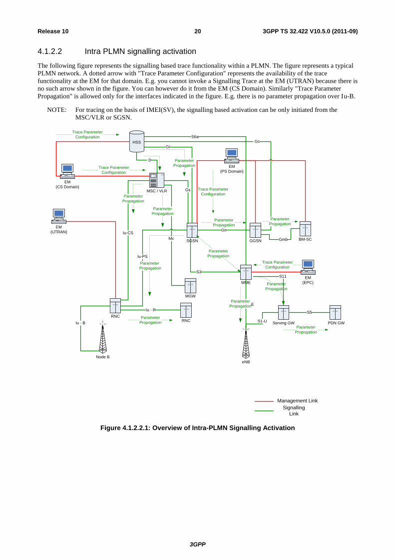
4.1.2.2 Intra PLMN signalling activation
The following figure represents the signalling based trace functionality within a PLMN. The figure represents a typical
PLMN network. A dotted arrow with "Trace Parameter Configuration" represents the availability of the trace
functionality at the EM for that domain. E.g. you cannot invoke a Signalling Trace at the EM (UTRAN) because there is
no such arrow shown in the figure. You can however do it from the EM (CS Domain). Similarly "Trace Parameter
Propagation" is allowed only for the interfaces indicated in the figure. E.g. there is no parameter propagation over Iu-B.
NOTE: For tracing on the basis of IMEI(SV), the signalling based activation can be only initiated from the
MSC/VLR or SGSN.
Gr
MSC / VLR
EM
(UTRAN)
RNCRNC
SGSN
EM
(CS Domain)
HSS
D
Iu-CS
Gs
Gn
Node B
EM
(PS Domain)
Iu - B
Signalling
Link
Management Link
Gc
Iu-PS
Iu - R
Trace Parameter
Configuration
Parameter
Propagation
Parameter
Propagation
Parameter
Propagation
Parameter
Propogation
Mc
Parameter
Propagation
Parameter
Propagation
MGW
Trace Parameter
Configuration
Trace Parameter
Configuration
GGSN BM-SCGmb
Parameter
Propagation
eNB
MME
EM
(EPC)
S3
S1-MME
Trace Parameter
Configuration
Parameter
Propagation
S6a
Serving GW PDN GW
Parameter
Propagation
S1-U
S5
S11
Parameter
Propagation
Parameter
Propogation
Figure 4.1.2.2.1: Overview of Intra-PLMN Signalling Activation

3GPP
3GPP TS 32.422 V10.5.0 (2011-09) 21 Release 10
4.1.2.3 Inter PLMN Signalling Activation
The following figure represents the signalling based trace functionality between PLMNs. This is particularly useful
when a roaming subscriber needs to be traced in a network. The figure represents a typical PLMN network and its
connections with another PLMN’s HSS. A dotted arrow with "Trace Parameter Configuration" represents the
availability of the trace functionality at the EM for that domain. E.g. you cannot invoke a Signalling Trace at the EM
(UTRAN) because there is no such arrow shown in the figure. You can however do it from the EM (CS Domain).
Similarly "Trace Parameter Propagation" is allowed only for the interfaces indicated in the figure. E.g. there is no
parameter propagation over Iu-B.
NOTE: There is no intention to allow tracing of a home subscriber roaming in a foreign network i.e. the trace
function is limited to a single PLMN.

3GPP
3GPP TS 32.422 V10.5.0 (2011-09) 22 Release 10
Gr
MSC / VLR
EM
(UTRAN)
RNCRNC
SGSN
EM
(CS Domain)
HSS
D
Iu-CS
Gs
MGW
Gn
Node B
EM
(PS Domain)
Iu - B
Signalling
Link
Management Link
Gc
Iu-PS
Iu - R
Parameter
Propagation
Parameter
Propagation
Parameter
Propagation
Parameter
Propogation
Mc
Parameter
Propagation
Trace Parameter
Configuration
Trace Parameter
Configuration
EM
PLMN - A
PLMN - B
GGSNBM-SC
Gmb
Parameter
Propagation
eNB
MME
EM
(EPC)
EM
(E-UTRAN)
S3
S1-MME
Trace Parameter
Configuration
Parameter
Propagation
S6a
Serving GW
PDN GW
S11
Parameter
Propagation
S1-U
S5
Parameter
Propogation
Parameter
Propagation
Figure 4.1.2.3.1: Overview of Inter-PLMN Signalling Activation

3GPP
3GPP TS 32.422 V10.5.0 (2011-09) 23 Release 10
4.1.2.4 UTRAN activation mechanisms
See subclause 4.2.3.1.
4.1.2.5 PS Domain activation mechanisms
The following figure shows the Trace Session activation in the PS domain. The figure is an example of tracing PDP
context.
EMS SGSNHSS
Storing Trace Control
& Configuration
parameters
UE
Storing Trace Control
& Configuration
parameters
Trace Session Activation
ATTACH_REQUEST
UPDATE_GPRS_LOCATION
MAP-ACTIVATE_TRACE_MODE
Starting Trace
Recording Session
GGSN
SM-ACTIVATE_PDP_CONTEXT_REQUEST
GTP-CREATE_PDP_CONTEXT_REQUEST
Starting Trace Session
& Trace Recording
Session
Figure 4.1.2.5.1: Trace session activation in PS domain for PDP Context
When a UE registers with the network by sending an ATTACH_REQUEST message to the SGSN, it updates the
location information in the HSS by sending the UPDATE_GPRS_LOCATION message to the HSS. The HSS checks if
the UE is being traced. If it is being traced, the HSS shall propagate the trace control and configuration parameters to
the SGSN by sending a MAP-ACTIVATE_TRACE_MODE - see 3GPP TS 29.002 [11] message to the SGSN. When
an inter-SGSN routing area update occurs, HSS shall send the MAP-ACTIVATE_TRACE_MODE message to the new
SGSN.
When SGSN receives the MAP-ACTIVATE_TRACE_MODE message it shall store the trace control and configuration
parameters and shall start a Trace Session.
When any of the triggering events defined in the trace control and configuration parameters occur, (e.g. PS session is
started (i.e. a ACTIVATE PDP CONTEXT REQUEST message is received from the UE)) the SGSN shall propagate
the trace control and configuration parameters to the GGSN (by sending a GTP-
CREATE_PDP_CONTEXT_REQUEST message) and to the radio network (by sending a RANAP-

3GPP
3GPP TS 32.422 V10.5.0 (2011-09) 24 Release 10
CN_INVOKE_TRACE message), if it is defined in the trace control and configuration parameters (NE types to trace).
The Trace Session activation to UTRAN is described in clauses 4.1.2.4.
When HSS sends the MAP-ACTIVATE_TRACE_MODE message to SGSN it shall include the following parameters
to the message:
IMSI (M).
Trace reference (M).
Triggering events for SGSN (M) and GGSN (M).
Trace Depth (M).
List of NE types to trace (M).
List of interfaces for SGSN (O), GGSN (O) and/or RNC (O).
When the SGSN sends the GTP-CREATE_PDP_CONTEXT_REQUEST message to GGSN it shall include the
following parameters to the message:
IMSI or IMEI (SV) (M).
Trace reference (M).
Trace Recording Session Reference (M).
Triggering events for GGSN (M).
Trace Depth (M).
List of interfaces for GGSN (O).
The following figure is an example of tracing for MBMS Context.

3GPP
3GPP TS 32.422 V10.5.0 (2011-09) 25 Release 10
EMS HSS SGSN UE GGSN
Attach_Request
Trace Session Activation
SM_Activate_MBMS_Context_Request
Update_GPRS_Location
MAP_Activate_Trace_Mode
GTP_Create_MBMS_Context_Request
Storing Trace Control
& Configuration
Parameters
Storing Trace Control
& Configuration
Parameters
Starting Trace
Recording Session
Starting Trace
Recording Session
BM-SC
Diameter Gmb AAR
Starting Trace
Recording Session
Figure 4.1.2.5.2: Trace session activation in PS domain for MBMSContext
When HSS receives a Trace Session activation from its EMS, it shall store the received trace control and configuration
parameters. At this point a Trace Session shall be started in the HSS.
When a UE registers with the network by sending an ATTACH_REQUEST message to the SGSN, it updates the
location information in the HSS by sending the UPDATE_GPRS_LOCATION message to the HSS. The HSS checks if
the UE is being traced. If it is being traced, the HSS shall propagate the trace control and configuration parameters to
the SGSN by sending a MAP-ACTIVATE_TRACE_MODE message to the SGSN. When an inter-SGSN routing area
update occurs, HSS shall send the MAP-ACTIVATE_TRACE_MODE message to the new SGSN.
When SGSN receives the MAP-ACTIVATE_TRACE_MODE message it shall store the trace control and configuration
parameters and shall start a Trace Session.
When any of the triggering events defined in the trace control and configuration parameters occur, (i.e. an ACTIVATE
MBMS CONTEXT REQUEST message is sent to the UE)) the SGSN shall propagate the trace control and
configuration parameters to the GGSN (by sending a GTP-CREATE_MBMS_CONTEXT_REQUEST message) and to
the radio network (by sending a RANAP-CN_INVOKE_TRACE message), if it is defined in the trace control and
configuration parameters (NE types to trace). The Trace Session activation to UTRAN is described in clauses 4.1.2.4.
The GGSN shall propagate the trace control and configuration parameters to the BM-SC (by sending a Diameter Gmb
AAR message) if the BM-SC is defined in the trace control and configuration parameters (NE types to trace).
When HSS sends the MAP-ACTIVATE_TRACE_MODE message to SGSN it shall include the following parameters
in the message:
IMSI (M).
Trace reference (M).
Triggering events for SGSN (M), GGSN (M) and BM-SC (M).
Trace Depth (M).

3GPP
3GPP TS 32.422 V10.5.0 (2011-09) 26 Release 10
List of NE types to trace (M).
List of interfaces for SGSN (O), GGSN (O), BM-SC (O) and/or RNC (O).
When the SGSN sends the GTP-CREATE_MBMS_CONTEXT_REQUEST message to GGSN it shall include the
following parameters in the message:
IMSI or IMEI (SV) (M).
Trace reference (M).
Trace Recording Session Reference (M).
Triggering events for GGSN (M) and BM-SC (M).
Trace Depth (M).
List of interfaces for GGSN (O) and BM-SC (O).
When the GGSN sends the Diameter Gmb AAR message to the BM-SC it shall include the following parameters in the
message:
IMSI or IMEI (SV) (M).
Trace reference (M).
Trace Recording Session Reference (M).
Triggering events for BM-SC (M).
Trace Depth (M).
List of interfaces for BM-SC (O).

3GPP
3GPP TS 32.422 V10.5.0 (2011-09) 27 Release 10
4.1.2.6 CS Domain activation mechanisms
The following figure shows the Trace Session activation in the CS domain. The figure is an example of tracing Mobile
Originating Call.
EMS MSS/VLRHSS
Storing Trace Control
& Configuration
parameters
UE
Storing Trace Control
& Configuration
parameters
Trace Session Activation
LOCATION_UPDATING_REQUEST
UPDATE_LOCATION
MAP-ACTIVATE_TRACE_MODE
Starting Trace Session
MGW
Starting Trace
Recording Session
Starting Trace Session
CM-SERVICE_REQUEST
MEGACO-Trace package with ADD
command
Figure 4.1.2.6.1: Trace Session Activation in CS domain
When HSS receives Trace Session activation from the EMS it should store the trace control and configuration
parameters associated to the Trace Session.
If the UE registers to the network, by sending a LOCATION UPDATING REQUEST message to the MSC/VLR, the
MSC Server/VLR updates the location information in the HSS by sending the MAP-UPDATE_LOCATION message to
the HSS. After receiving the UPDATE_LOCATION message HSS shall propagate the trace control and configuration
parameters by sending a MAP-ACTIVATE_TRACE_MODE message to the MSC Server/VLR.
When the MSC Server/VLR receives the MAP-ACTIVATE_TRACE_MODE message from the HSS, it shall store the
trace control and configuration parameters.
When any of the triggering event, defined in the trace control and configuration parameters, occurs (e.g. in case of
Mobile Originating Call is started (i.e. the MSC Server receives the CM_SERVICE_REQUEST message with service
type set to originating call establishment)) the MSC Server should propagate the trace control and configuration
parameters to the MGW (by sending an ADD command with a trace package - see 3GPP TS 29.232 [10]) and to the
radio network if it is defined in the trace control and configuration parameters (NE types to trace). Trace Session
3GPP
3GPP TS 32.422 V10.5.0 (2011-09) 28 Release 10
activation for UTRAN is described in clauses 4.1.2.4. In case of inter-MSC Server handover the MSC Server-A should
propagate the trace control and configuration parameters to the MSC Server-B.
When HSS sends the MAP-ACTIVATE_TRACE_MODE message to MSC Server it shall include the following
parameters to the message:
IMSI (M).
Trace reference (M).
Triggering events for MSC Server (M) and MGW (M) .
Trace Depth (M).
List of NE types to trace (M).
List of interfaces for MSC Server (O), MGW (O) and/or RNC (O).
When the MSC Server sends the ADD command with trace package to MGW it shall include the following parameters
to the message:
IMSI or IMEI (SV) (M).
Trace reference (M).
Trace Recording Session Reference (M).
Triggering events for MGW (M).
Trace Depth (M).
List of interfaces for MGW (O).
4.1.2.7 Void
4.1.2.8 Tracing roaming subscribers
If a HPLMN operator activates a Trace Session for a home subscriber, while it (MS) is roaming in a VPLMN, it (HSS)
may restrict the propagation of the Trace Session activation message to a MSC Server/VLR or to a SGSN located in the
VPLMN.
Also, a MSC Server/VLR or a SGSN located in a VPLMN may accept any Trace Session activation message(s) coming
from an HSS located in another PLMN. However, there shall be a capability to reject activations from another PLMN.
4.1.2.9 Service Level Tracing for IMS activation mechanisms
4.1.2.9.1 General
Figure 4.1.2.9.1.1 illustrates signalling based activation for service level tracing within a home IM CN SS and a visited
IM CN SS. An arrow with "Trace Parameter Configuration" represents the availability of the trace functionality at the
EM for that domain. Similarly, An arrow with "Trace Parameter Propagation" represents the ability to propagate trace
parameters only for the interfaces indicated.

3GPP
3GPP TS 32.422 V10.5.0 (2011-09) 29 Release 10
Sh
P-CSCF
EM
(IMS Domain)
HSS
Signalling Link
Management Link
Trace Parameter
Configuration
S-CSCF I-CSCFAS
Cx
Parameter
Propagation
MRF MGCF
Mr
Parameter
Propagation
Cx
Mw
Parameter
Propagation
Mw
Mg
EM
(UE)
Gm
BGCF
Mi
Trace Parameter
Configuration
Parameter
PropagationParameter
Propagation
Parameter
Propagation
Parameter
Propagation
Parameter
Propagation
Parameter
Propagation
UE
Parameter
Propagation
Figure 4.1.2.9.1.1: Overview of Signalling Activation for service level tracing for IMS
Trace Activation shall be initiated from the Core Network EM only [EM (UE), and EM (HSS)].
The EM (UE) and the interactions between the EM (UE) and the UE shall be achieved using OMA Device Management
[18].
When service level tracing for IMS is required for a registered home subscriber in the home IM CN SS Trace Session
activation shall go to the UE and the HSS. The HSS shall propagate the Trace Session activation to the S-CSCF, I-
CSCF and the AS.
The S-CSCF and I-CSCF shall propagate the Trace Session activation to the P-CSCF. The Trace Session activation
shall be propagated to the MRF, MGCF and BGCF via the S-CSCF. When an IMS NE (i.e. S/I/P-CSCF, AS, HSS,
MRF, MGCF, BGCF) receives Trace Session activation it shall save the received Trace control and configuration
parameters and shall start a Trace Session.
When service level tracing for IMS is required for a registered home subscriber in a visited IM CN SS Trace Session
activation shall go to the UE and the HSS. The HSS shall propagate the Trace Session activation to the S-CSCF, I-
CSCF and the AS. The I-CSCF may prohibit the propagation of the Trace Session activation from the home IM CN SS
to the P-CSCF in the visited IM CN SS.
Editor’s Note: The ability to send Trace session activation to the S/I-CSCF in the home IM CN SS in the situation
where it is not possible to send Trace Session activation to a UE is FFS.

3GPP
3GPP TS 32.422 V10.5.0 (2011-09) 30 Release 10
4.1.2.9.2 Trace session activation for non-registered UE
Figure 4.1.2.9.2.1 illustrates the sending of Trace Session activation towards the HSS, S-CSCF, I-CSCF, AS and
P-CSCF during the registration of a UE with the IM CN SS.
As described in 3GPP TS 23.228 [15] for the purposes of signalling flows the user is considered always to be roaming.
For a user roaming in their home network, the home network shall perform the role of the visited network elements and
the home network elements.
NOTE: For detailed information of application level registration procedures for IMS see 3GPP TS 23.228 [15].
UE I-CSCF HSS EMP-CSCF S-CSCF
4. REGISTER
5. REGISTER
6. Cx-Query/
Cx-Select-Pull7. Cx-Query/
Cx-Select-Pull Resp.
8. REGISTER
9. Cx-Put/ Cx-Pull
10. Cx-Put/
Cx-Pull Resp.
18. 200 OK
(incl. Trace Session activation)
20. 200 OK
(incl. Trace Session activation)
22. 200 OK
3.Storing Trace Control &
Configuration parameters
12. Storing Trace Control &
Configuration parameters
19. Storing Trace Control &
Configuration parameters
21. Storing Trace Control &
Configuration parameters
AS
11. Service Control
(incl. Trace session activation)
2. Update of user’s
profile information
1. Trace Session Activation
17. Storing Trace
Control & Configuration
parameters
13. Third Party REGISTER
14. 200 OK
15. Sh-Pull
16. Sh-Pull Resp.
(incl. Trace Session Activation)
Figure 4.1.2.9.2.1: Trace Session activation for non-registered user

3GPP
3GPP TS 32.422 V10.5.0 (2011-09) 31 Release 10
When HSS receives Trace Session activation from its EM (Step 1), it shall update the user information associated with
the user for whom the trace is to be applied (Step 2). The HSS shall store the received trace control and configuration
parameters (Step 3). At this point a Trace Session shall be started in the HSS.
When the EM sends the Trace Session activation to the HSS it shall include the following trace and configuration
parameters in the message:
Public User Identity (i.e. Identity of user initiating/terminating the service to be traced) (M)
Service identification (M)
Trace reference (M)
Triggering events for HSS (M)
Trace depth (M)
List of NE types (M)
Triggering events for S-CSCF (M), I-CSCF (M), P-CSCF (M), AS (M), BGCF (M), MRF (M), MGCF (M)
Trace depth (M)
When the EM sends the Trace Session activation to the HSS it may include the following trace and configuration
parameters in the message if required:
List of interfaces for HSS (O)
List of interfaces for S-CSCF (O), I-CSCF (O), P-CSCF (O), AS (O), BGCF (O), MRF (O), MGCF (O).
As described in 3GPP TS 23.228 [15] when a UE registers with the network by sending a REGISTER message (Steps 4
to 10), the HSS sends Service Control (user and filter information) to the S-CSCF (Steps 11). It shall also propagate
trace control and configuration parameters to the S-CSCF. At this point a Trace Session shall be started in the S-CSCF
(Step 12).
When the HSS sends the Cx-Put-Response operation to the S-CSCF (see 3GPP TS 29.228 [16]) it shall include the
following trace and configuration parameters:
Public User Identity (i.e. Identity of user initiating/terminating the service to be traced) (M)
Service identification (M)
Trace reference (M)
Triggering events for S-CSCF (M)
Trace depth (M)
List of NE types (M)
Triggering events for I-CSCF (M), P-CSCF (M), BGCF (M), MGCF (M)
When the HSS sends the Cx-Put-Response operation to the S-CSCF it may include the following trace and
configuration parameters if required:
List of interfaces for S-CSCF (O)
List of interfaces for I-CSCF (O), P-CSCF (O), BGCF (O), MGCF (O)
Editor’s Note: The sending of trace and configuration parameters as part of the Cx-Put-Response operation is for
FFS by CT4.
As described in 3GPP TS 23.218 [14] on reception of a REGISTER request, the S-CSCF shall send a third-party
REGISTER request to the Application Server if the registration request from the user matches a contained trigger as
downloaded from the HSS (Step 13 and 14).

3GPP
3GPP TS 32.422 V10.5.0 (2011-09) 32 Release 10
As described in 3GPP TS 29.328 [17] the Application Server shall request from the HSS information such as service
and user related information. In this case, the HSS shall determine that a trace request for the user is active and shall
return to the Application Server trace control and configuration parameters (Step 16). At this point a Trace Session shall
be started in the AS (Step 17).
When the HSS sends the Sh-Pull-Response operation to the AS (see 3GPP TS 29.328 [17]) it shall include the
following trace and configuration parameters:
Public User Identity (i.e. Identity of user initiating/terminating the service to be traced) (M).
Service identification (M)
Trace reference (M)
Triggering events for AS (M)
Trace depth (M)
List of NE types (M)
Triggering events for MRF (M)
When the HSS sends the Sh-Pull-Response operation to the AS it may include the following trace and configuration
parameters if required:
List of interfaces for AS (O)
List of interfaces for MRF (O)
Editor’s Note: The sending of trace and configuration parameters as part of the Sh-Pull-Response operation is for
FFS by CT4.
Upon successful registration the S-CSCF shall return a SIP 200 OK and shall propagate the received trace control and
configuration parameters to the I-CSCF (Step 18). At this point a Trace Session shall be started in the I-CSCF (Step 19).
When the S-CSCF sends the 200 OK (Register) message to the I-CSCF (see 3GPP TS 24.228 [15]) it shall include the
following trace and configuration parameters:
Public User Identity (i.e. Identity of user initiating/terminating the service to be traced) (M).
Service identification (M)
Trace reference (M)
Trace depth (M)
Triggering events for I-CSCF (M)
List of NE types (M)
Triggering events for P-CSCF (M)
When the S-CSCF sends the 200 OK (Register) message to the I-CSCF it may include the following trace and
configuration parameters if required:
List of interfaces for I-CSCF (O)
List of interfaces for P-CSCF (O)
If the P-CSCF resides in the same (i.e. home IM CN SS) network as the I-CSCF, the I-CSCF forwards the SIP 200 OK
and shall propagate the retrieved trace control and configuration parameters to the P-CSCF (Step 20). At this point a
Trace Session shall be started in the P-CSCF (Step 21).

3GPP
3GPP TS 32.422 V10.5.0 (2011-09) 33 Release 10
When the I-CSCF sends the 200 OK (Register) message to the P-CSCF (see 3GPP TS 24.228 [15]) it shall include the
following trace and configuration parameters:
Public User Identity (i.e. Identity of user initiating/terminating the traced service) (M)
Service identification (M)
Trace reference (M)
Trace depth (M)
Triggering events for P-CSCF (M)
List of NE types (M)
When the I-CSCF sends the 200 OK (Register) message to the P-CSCF it may include the following trace and
configuration parameters if required:
List of interfaces for P-CSCF (O).
If the P-CSCF resides in a different (i.e. visited IM CN SS) network as the I-CSCF, the I-CSCF forwards the SIP 200
OK and may propagate the retrieved trace control and configuration parameters to the P-CSCF. If the P-CSCF is in a
different network than the I-CSCF and the sending of trace control and configuration parameters from the home IM CN
SS to the visited IM CN SS is prohibited then the I-CSCF shall restrict the sending of the trace control and
configuration parameters.
The P-CSCF shall forward the SIP 200 OK to the UE. The P-CSCF shall not send the retrieved trace control and
configuration parameters.

3GPP
3GPP TS 32.422 V10.5.0 (2011-09) 34 Release 10
4.1.2.9.3 Trace session activation for a registered UE
Figure 4.1.2.9.3.1 illustrates the sending of Trace Session activation towards the HSS, S-CSCF, I-CSCF, AS and P-
CSCF during the re-registration of a UE with the IM CN SS.
As described in 3GPP TS 23.228 [15] periodic application level re-registration is initiated by the UE either to refresh an
existing registration or in response to a change in the registration status of the UE. Re-registration follows the same
process as that defined for registration of a non-registered user.
UE I-CSCF HSS EMP-CSCF S-CSCF
4. REGISTER
5. REGISTER
6. Cx-Query
7. Cx-Query Resp.
8. REGISTER
9. Cx-Put/ Cx-Pull
10. Cx-Put/
Cx-Pull Resp.
18. 200 OK
(incl. Trace Session activation)
20. 200 OK
(incl. Trace Session activation)
22. 200 OK
3.Storing Trace Control &
Configuration parameters
12. Storing Trace Control &
Configuration parameters
19. Storing Trace Control &
Configuration parameters
21. Storing Trace Control &
Configuration parameters
AS
11. Service Control
(incl. Trace session activation)
2. Update of user’s
profile information
1. Trace Session Activation
17. Storing Trace
Control & Configuration
parameters
13. Third Party REGISTER
14. 200 OK
15. Sh-Pull
16. Sh-Pull Resp.
(incl. Trace Session Activation)
Figure 4.1.2.9.3.1: Trace Session activation for registered UE
When HSS receives Trace Session activation from its EM (Step 1), it shall update the user information associated with
the user for whom the trace is to be applied (Step 2). The HSS shall store the received trace control and configuration
parameters (Step 3). At this point a Trace Session shall be started in the HSS.
When the EM sends the Trace Session activation to the HSS it shall include the trace and configuration parameters as
described in clause 4.1.2.9.2.
Prior to expiry of the agreed registration timer, the UE initiates a re-registration by sending a REGISTER message.
The subsequent steps of re-registration of the UE as described in 3GPP TS 23.228 [15] and the signalling flow steps as
described in subclause 4.1.2.9.2 apply.
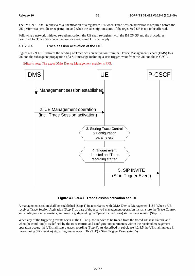
3GPP
3GPP TS 32.422 V10.5.0 (2011-09) 35 Release 10
The IM CN SS shall request a re-authentication of a registered UE when Trace Session activation is required before the
UE performs a periodic re-registration, and when the subscription status of the registered UE is not to be affected.
Following a network initiated re-authentication, the UE shall re-register with the IM CN SS and the procedures
described for Trace Session activation for a registered UE shall apply.
4.1.2.9.4 Trace session activation at the UE
Figure 4.1.2.9.4.1 illustrates the sending of Trace Session activation from the Device Management Server (DMS) to a
UE and the subsequent propagation of a SIP message including a start trigger event from the UE and the P-CSCF.
Editor’s note: The exact OMA Device Management enabler is FFS.
2. UE Management operation
(incl. Trace Session activation)
3. Storing Trace Control
& Configuration
parameters
1. Management session established
DMS UE P-CSCF
5. SIP INVITE
(Start Trigger Event)
4. Trigger event
detected and Trace
recording started
Figure 4.1.2.9.4.1: Trace Session activation at a UE
A management session shall be established (Step 1) in accordance with OMA Device Management [18]. When a UE
receives Trace Session Activation (Step 2) as part of the received management operation it shall store the Trace Control
and configuration parameters, and may (e.g. depending on Operator conditions) start a trace session (Step 3).
When any of the triggering events occur at the UE (e.g. the service to be traced from the traced UE is initiated), and
when the condition(s) as defined by the trace control and configuration parameters within the received management
operation occur, the UE shall start a trace recording (Step 4). As described in subclause 4.2.3.5 the UE shall include in
the outgoing SIP (service) signalling message (e.g. INVITE) a Start Trigger Event (Step 5).

3GPP
3GPP TS 32.422 V10.5.0 (2011-09) 36 Release 10
4.1.2.10 EPC activation mechanism
4.1.2.10.1 UE attached to EPC via E-UTRAN
Figure 4.1.2.10.1 summarizes the Trace Session activation procedure in EPC:
Starting Trace Session
Create Session Request
Starting Trace Session
Storing Trace Control &
Configuration Parameters
EMS HSS MME PGW SGW
Attach_Request
Trace Session
Activation
Update Location
Request Update Location
Answer
eNodeB UE
Attach_Request
Create Session Request
Create Session
Response Create Session
Response Initial Context Setup
Request Storing Trace Control &
Configuration Parameters
Storing Trace Control &
Configuration Parameters
Storing Trace Control
& Configuration
Storing Trace Control & Configuration Parameters
Starting Trace Session
Starting Trace Session
Figure 4.1.2.10.1: Trace Session activation procedure in EPC with GTP based S5 interface:
The Trace Session activation in MME can come for a home subscriber trace from HSS via the S6a interface or for a
foreign subscriber from the EM of MME.
When the UE makes an attach request to the MME, it updates the location information in the HSS. The HSS checks
if the UE is being traced. If it is being traced, the HSS shall propagate the trace control and configuration data to the
MME by including the trace control and configuration parameters into the S6a-Insert subscriber data message or the
S6a-Update Location Answer message. If the traced UE has already attached before receiving the Trace Session
Activation from the EM/NM, the HSS shall also propagate the trace control and configuration data to the MME by
either S6a-Insert subscriber data message or the S6a-Update Location Answer message. When MME receives the
trace control and configuration data from the HSS it shall store the information and shall start a Trace Session.

3GPP
3GPP TS 32.422 V10.5.0 (2011-09) 37 Release 10
During inter-MME TAU, the MME shall propagate the trace control and configuration parameters to the target
MME within an S10- Context Response as part of inter-MME TAU procedures. During attach procedures where the
context information is requested from the target MME, the MME shall propagate the trace control and configuration
parameters within an S10-Identification Response message. During inter-MME handover, the MME shall propagate
the trace control and configuration parameters to the target MME within an S10- Forward Relocation Request
message as part of inter-MME handover procedures.
If the List of NE Types parameter specifies tracing in the SGW and/or Tracing in the PGW, MME shall propagate
the trace control and configuration parameters via the S11 interface to the SGW per one of the following messages:
1. if a default bearer connection has not been established, via the S11: Create Session Request message
2. otherwise via the S11-Trace Session Activation message
The SGW upon receiving the trace control and configuration parameters shall start a trace session.
If the List of NE Types parameter specifies Tracing in the PGW, SGW shall propagate the trace control and
configuration parameters via the S5 interface to the PGW per one of the following messages:
1. if a default bearer connection has not been established, via the S5: Create Session Request message
2. otherwise via the S5-Trace Session Activation message
The PGW upon receiving the trace control and configuration parameters shall start a trace session.
When a triggering events, defined in the trace control and configuration data occur (i.e. a session is started) a Trace
Recording Session shall be started and the trace control and configuration data shall be propagated to the radio
network to the eNB if the List of NE Types parameter specifies eNB tracing. See section 4.2.3.6.
When HSS activates the trace to the MME the following trace control and configuration parameters shall be
included in the message:
IMSI or IMEISV
Trace Reference
Triggering events for MME, Serving GW, PDN GW
Trace Depth
List of NE types to trace
List of Interfaces for MME, Serving GW, PDN GW, eNB
IP address of Trace Collection Entity
When MME activates the trace to the SGW the following trace control and configuration parameters shall be
included in the message::
IMSI or IMEISV
Trace Reference
Triggering events for Serving GW, PDN GW
Trace Depth
List of NE types to trace
List of Interfaces for Serving GW, PDN GW
IP address of Trace Collection Entity
When SGW activates the trace to the PGW the following trace control and configuration parameters shall be
included in the message:
IMSI or IMEISV

3GPP
3GPP TS 32.422 V10.5.0 (2011-09) 38 Release 10
Trace Reference
Triggering events for PDN GW
Trace Depth
List of Interfaces for PDN GW
IP address of Trace Collection Entity
When MME sends the trace control and configuration parameters to the eNB the following information shall be
included in the message:
Trace Reference
Trace Recording Session Reference
Trace Depth
IP Address of Trace Collection Entity
and the following information may be included in the message:
List of Interfaces for eNB
Figure 4.1.2.10.1.A illustrates the Trace Session activation in case of PMIP based S5 interface. The figure contains only
the difference compare to the GTP based S5 interface
SGW PGW PCRF
Trace Session Activation
Trace Session Activated
/ Trace Recording
Session Started
Storing Trace Control &
Configuration Parameters
Starting Trace
Recording Session
Trace Session Activation
Figure 4.1.2.10.1.A: Trace Session Activation from SWG to PGW in case of PMIP based S5 interface
When the SGW receives the Trace Session activation message and the List of NE Type to trace parameter specifies
Tracing in the PDN GW , SGW shall send Trace Session Activation to PDN GW via the PCRF. The Trace Session
activation can be done as part of the IP CAN session establishment or as a standalone procedure [29].
The Trace Session Activation shall include the following information:
IMSI or IMEISV
Trace reference
Trace Recording Session Reference
Trace Depth
Triggering events for PDN GW

3GPP
3GPP TS 32.422 V10.5.0 (2011-09) 39 Release 10
List of Interfaces for PDN GW
IP address of Trace Collection Entity
When the PCRF receives the Trace Session Activation it shall forward the same trace control and configuration
parameters to the PDN GW [29].
4.1.2.10.2 UE attached to EPC via non-3GPP accesses with DSMIPv6 on S2c or PMIP on
S2a/S2b
Figure 4.1.2.10.2 illustrates the Trace Session activation when the UE is attached from a non-3GPP access network with
DSMIPv6 on S2c or PMIP on S2a or S2b interface.
Figure 4.1.2.10.2: Trace Session activation procedure to PGW in case of UE attaches from non-3GPP access network via DSMIPv6 on S2c or PMIP on S2a/S2b
When the UE attaches to the EPC network via a non-3GPP access network the Trace Session activation to the PGW can
be done via HSS and AAA server. Therefore when the UE attach is signalled to the HSS via non-3GPP access network,
the HSS shall send the Trace control and configuration parameters to the AAA server as part of the user profile
download [25]. The following information shall be included in the downloaded user data:
IMSI, or IMEI(SV)
Trace Reference
Triggering event for PGW
Trace Depth
List of interface for PGW
IP address of Trace Collection Entity
UE MAG PDN GW3GPP AAA
server HSS
Authentication and Authorization
Attach
User Profile request
User Profile Download
(Trace Info)
DSMIP: Binding Update
Storing Trace control
and configuration
paramaters
Authorization request
Authorization Answer
(Trace Info)
Option A
PMIP: Proxy Binding
UpdateOption B
Storing Trace control
and configuration
paramaters
Storing Trace control
and configuration
paramaters
EM
Trace Session Activation
Authorization request
Authorization Answer
(Trace Info)

3GPP
3GPP TS 32.422 V10.5.0 (2011-09) 40 Release 10
When the AAA server receives the user profile, which contains also the trace control and configuration parameters, it
shall store the received trace control and configuration parameters. The AAA server shall forward the received trace
control and configuration parameters in the authorization when it receives the authorization request from the PGW
during the PDN connectivity.
The event, which triggers the authorization in the PDN GW depend on the used IP mobility protocol:
- In case of DSMIP (option A), it is a binding update received from the UE,
- In case of PMIP (Option B), it is a proxy binding update request received from the Trusted Non-3GPP GW or
ePDG playing the role of the Mobile Access Gateway (MAG)
If the UE is already registered to the HSS by a AAA server via the SWx interface, Trace Session activation shall also be
possible from the HSS to the PDN GW via the AAA server. In that case the HSS sends the Trace Session activation
message with a push profile request.
The AAA server shall examine the received user profile and if Trace Session activation is needed in the PDN GW, it
shall initiate a re-authorization procedure towards the PDN GW. The Trace Session is activated to te PDN GW using
this re-authorization procedure. When PDN GW receives the Trace Session activation message, it shall save the
received trace control and configuration parameters.
4.1.2.10.3 UE attached to EPC via non-3GPP accesses with GTP on S2b interface
Figure 4.1.2.10.3 illustrates the Trace Session activation when the UE is attached from a non-3GPP access with GTP
on the S2b interface.
UE ePDG PDN GW3GPP AAA
server HSS
Authentication and Authorization
Includes Trace information)
Attach
User Profile request
User Profile Download
(Trace Info )
Storing Trace control
and configuration
parameters
GTP : Create Session
Request
Includes trace
info
Option C
Storing Trace control
and configuration
paramaters
EM
Trace Session Activation
Authorization request
Authorization Answer
Figure 4.1.2.10.3 : Trace Session activation procedure to PGW when the UE is attaches to EPC from a non-3GPP access with GTP based S2b
When the UE attaches to the EPC network via a non-3GPP access network the Trace Session activation to the PGW can
be done via HSS, AAA server and ePDG. Therefore when the UE attach is signalled to the HSS via non-3GPP access

3GPP
3GPP TS 32.422 V10.5.0 (2011-09) 41 Release 10
network, the HSS shall send the Trace control and configuration parameters to the AAA server as part of the user
profile download (see [22] , [25] and [34]).
The following information shall be included in the downloaded user data:
IMSI, or IMEI(SV)
Trace Reference
Triggering event for PGW
Trace Depth
List of interface for PGW
IP address of Trace Collection Entity
The ePDG sends a GTPv2 Create Session Request which contains trace information message to the PGW. The RAT
type indicates the non-3GPP IP access technology type.
Figure 4.1.2.10.4 illustrates the Trace Session activation when the UE is already attached from a non-3GPP access with
GTP based S2b, i.e. trace session activation after a session has been created.
If the UE is already registered to the HSS by a AAA server via the SWx interface, Trace Session activation shall also be
possible from the ePDG to the PDN GW. In that case the HSS sends the Trace activation message with a push profile
request.
ePDG PDN-GW AAA EM
Push Profile Request
(Trace Info)
HSS
Authorization request
Trace activated
Authorization response
Incl trace info)
:
Trace activated
Authorization request
Authorization Answer
Trace Session
Activation
Trace Activation
Re-authorization request
Re-authorization response
Figure 4.1.2.10.4 : Trace Session activation procedure to PGW when the UE is already attached to EPC from a non-3GPP access with GTP based S2b
The AAA shall examine the received information and if Trace Session activation is needed in the PDN GW, it shall
initiate a reauthorization request towards the ePDG. ePDG sends a GTPv2 Trace Session Activation message to the
PGW when determining from the updated profile that a trace activation is needed. When PDN GW receives the Trace
Session activation message, it shall save the received trace control and configuration parameters.
Trace Activation

3GPP
3GPP TS 32.422 V10.5.0 (2011-09) 42 Release 10
4.1.2.11 E-UTRAN activation mechanisms
The Trace Session should be activated in in an eNB when the eNB receives the TRACE START, INITIAL CONTEXT
SETUP REQUEST or HANDOVER REQUEST message with the IE Trace Activation from the MME and if some
activities have been started on the interfaces that have been requested to be traced.
If the subscriber or equipment which is traced makes a handover to a target eNB using the X2 interface, the source eNB
should propagate the trace control and configuration parameters further to the target eNB by using the HANDOVER
REQUEST message. When the target eNB receives the HANDOVER REQUEST message it should immediately start a
Trace Session according to the trace control and configuration parameters received in the HANDOVER REQUEST
message.
If the subscriber or equipment which is traced makes a handover to a target eNB using the S1 interface, it is the MME's
responsibility to propagate the trace control and configuration parameters to the target eNB.
Interaction with Relocation
If the tracing shall continue also after the relocation has been performed, the CN Invoke Trace procedure shall be re-
initiated from the CN towards the future eNB after the Relocation Resource Allocation procedure has been executed
successfully.
The TRACE START, INITIAL CONTEXT SETUP REQUEST or HANDOVER REQUEST message that is received
from the MME contains the following information:
Trace Reference
including Trace Recording Session Reference
Trace Depth
List of interfaces for eNB
IP address of Trace Collection Entity
If the Trace Reference is the same as an existing Trace Session for the same subscriber or equipment, the eNB shall not
activate a new Trace Session and the existing Trace Session will not be impacted. See clause 4.2.3.6 for the conditions
on whether or not the Trace Recording Session should be started.
If the Trace Reference is the same as an existing Trace Session for different subscriber(s) or equipment(s), the eNB
shall not activate a new Trace Session, and the eNB shall not start a new Trace Recording Session.
4.1.2.12 EPC Activation mechanism for MDT
4.1.2.12.1 General
UE measurements activation extends the EPC trace activation procedure, as described in 4.1.2.10. When a Trace
Session is activated, configuration parameters of MDT are added into the message.
For IMSI/IMEI(SV) based UE selection, or IMSI/IMEI(SV) combined with geographical area based UE selection, UE
performance measurements activation request is propagated to UE finally.
This mechanism works for the following input parameters:
IMSI only or
IMSI and area information or
IMEI(SV) only or
IMEI(SV) and area information or
After the IMSI or IMEISV user attached to the network, the MME shall forward the MDT configurations to the
corresponding eNB which serves the IMSI or IMEISV user. If the area criterion is specified and is not satisfied, the
MME shall keep the MDT configuration first and then forward it to the serving eNB only when the area criterion is
satisfied.

3GPP
3GPP TS 32.422 V10.5.0 (2011-09) 43 Release 10
MDT criteria checking on eNB:
For immediate MDT, after eNB got the MDT configuration, the eNB can detect the area information and
decide whether the selected IMSI/IMEISV can fit into the criteria for initiating MDT data collection. If the
area information criterion is not met, the eNB keeps the MDT configuration and propagates it during
handover as specified in section 4.2.6.
For logged MDT, the eNB will forward the MDT configuration criteria to the selected IMSI/IMEISV. The
area criteria checking will be done at UE side after UE received the MDT configuration criteria.
MDT criteria checking on UE:
For immediate MDT, there is no need to do MDT criteria checking on UE.
For logged MDT, The area criteria checking will be done at UE side after UE received the MDT
configuration criteria.
In case of logged MDT, after UE receives from eNodeB the configuration parameters via the message RRC Connection
Reconfiguration, it detects whether it stays within the specified area. If yes the UE will execute measurement job.
Otherwise UE will do nothing but waiting.
In case of Immediate MDT trace (e.g., IMSI/IMEI based selection), the Immediate MDT trace session context of the
UE shall be preserved in the network when the UE enters idle mode.
The Logged MDT trace session is preserved in the UE until the duration time of the trace session expires, including also
multiple idle periods interrupted by idle-connected-idle state transitions.
The Logged MDT trace session context of the UE is stored in the network as long as the trace session is active,
including also the periods when the UE is in connected state.
Two scenarios shall be considered according to UE status when EMS activates UE based measurements job: before UE
attachment, after UE attachment, different procedures are described in 4.1.2.12.2, 4.1.2.12.3.
4.1.2.12.2 Activation of MDT task before UE attaches to the network
As shown in figure 4.1.2.12.1, by adding configurations of MDT EMS activate the Trace Session for UE measurements
job.

3GPP
3GPP TS 32.422 V10.5.0 (2011-09) 44 Release 10
EMS HSS MME PGW SGW
Attach_Request Trace Session Activation (MDT configuration)
Create Session Request
Update Location Request
Update Location Answer (MDT configuration)
Storing Trace Control &
Configuration
Starting Trace
Recording Session
eNodeB UE
Attach_Request
Create Session Request
Create Session Response
Create Session Response
Initial Context Setup Request (MDT configuration)
Storing Trace Control &
Configuration Parameters
Starting Trace
Recording Session
Starting Trace
Recording Session
Storing Trace Control &
Configuration Parameters
Storing Trace Control &
Configuration Parameters
Storing Trace Control &
Configuration Parameters
RRC Connection reconfiguration
(MDT configuration)
RRC Connection reconfiguration
Complete
Starting Trace
Recording Session
MDT Criteria checking
on eNB
MDT Criteria checking
on UE
Figure 4.1.2.12.1: MDT activation procedure in EPC
When HSS activates the trace, for MDT job, to the MME the following configuration parameters shall be included
in the message:
jobType
IMSI or IMEISV
Area scope (e.g. TA, Cell)
Trace Reference
List of measurements
Reporting Trigger
Report Interval
Report Amount
Event Threshold
Logging Interval

3GPP
3GPP TS 32.422 V10.5.0 (2011-09) 45 Release 10
Logging duration
Note that at the same time not all the parameters can be present. The conditions are described in Section
5.10 of this document.
IP address of Trace Collection Entity
The Specified geographical area field is available when IMSI/IMEI(SV) combined with geographical area are
needed for UE selection.
When MME activate MDT activation to eNodeB, the MDT configuration parameters can be included in the message
in the Initial Context Setup:
Area scope (TA, Cell)
Trace Reference
Trace Recording Session Reference
List of measurements
Reporting Trigger
Report Amount
Report Interval
Event Threshold
Logging Interval
Logging Duration
IP address of Trace Collection Entity
Note that at the same time not all the parameters can be present. The conditions are described in Section 5.10 of this
document.
The MME receives and stores MDT user consent indication from HSS as part of subscriber information when user
context is established in MME at UE attachment. The MME shall consider the MDT user consent information when
activating an MDT trace session for the UE. Details on the user consent handling

3GPP
3GPP TS 32.422 V10.5.0 (2011-09) 46 Release 10
4.1.2.12.3 Activation of MDT task after UE attachment
EMS HSS MME
Trace Session Activation (MDT configuration)
Insert subscriber data (MDT configuration)
ENode
B UE
Trace Start (MDT configuration)
RRC Connection Reconfiguration
(MDT configuration) RRC Connection Reconfiguration
Complete
UE access to network by attach procedure
Storing Trace Control &
Configuration
Storing Trace Control & Configuration Parameters
Storing Trace Control &
Configuration Parameters
Starting Trace
Recording Session
MDT criteria checking on
eNB
MDT criteria checking on UE
Figure 4.1.2.12.2: MDT activation in EPC after UE attachment
The messages propagated to HSS, MME and eNodeB are the same as described in clause 4.1.2.12.2.
When MME can send Trace Start to eNodeB, the following configuration parameters shall be included in the
message:
Area scope (TA, Cell)
Trace Reference
Selected UE Measurements
IP address of Trace Collection Entity
The MME shall consider the MDT user consent information when activating an MDT trace session for the UE. Detailed
procedures about user consent is described in Section 4.2.8.1.
In case of logged MDT and the UE is currently being in idle mode, the MME is not required to initiate paging of the UE
in order to send the configuration.
Then eNodeB initiates RRC Connection Reconfiguration Request in case of immediate MDT or the
IdleMDTConfiguration RRC message in case of logged MDT toward the UE and sends the MDT measurement
configuration parameters as received from the MME.
Immediate/Logged signalling based MDT criteria may consist of a cell list. MME shall validate whether the serving cell
is controlled by the same eNodeB as any other cell in the cell list. If yes, the MDT activation shall be sent to the serving
eNodeB.

3GPP
3GPP TS 32.422 V10.5.0 (2011-09) 47 Release 10
4.1.2.12.4 Handling of various scenarios during MDT activation
Handling of various scenarios for Signalling based Logged/Immediate MDT are addressed below:
1. EM initiating MDT activation shall validate that the MCC and MNC specified in the Trace reference is the
same as the PLMN supported by all the cells specified in the area scope If the eNodeB receives a request with
a PLMN in the TraceReference that does not match any PLMN in its list , it shall ignore the request
2. MME shall be informed with an error indication by the eNodeB when the UE configured for signalling based
Logged MDT is not MDT capable. An error message indicating that the UE is not MDT capable shall be sent
to the EM which should subsequently deactivate the MDT trace session so that all resources can be
appropriately cleaned up.
3. MME shall be informed with an error indication if the eNodeB could not configure the UE because it was in
the middle of a handover. MME shall try to reactivate MDT in the target cell if the target cell scope meets the
MDT criteria.
4. MME shall be informed with an error indication if the Logged MDT configuration could not be signalled to the
UE before end of the call or RLF. MME shall re-evaluate criteria and re-activate MDT when the UE
reconnects.
5. When the UE re-enters PLMN (specified in trace reference) then the MME shall be responsible for restarting
the Immediate MDT activation (if it is as a result of an X2 handover then one option is MME could use the
path switch request as trigger). However this is best effort. There can be cases where MME may not be able to
restart the MDT when the UE re-enters the PLMN (specified in area scope): for example: If the UE performs
intra eNB handover where path switch is not necessarily sent, the MME may not be able to restart MDT
4.1.2.13 PS domain activation mechanism for MDT
4.1.2.13.1 General
MDT activation in PS domain extends the trace activation procedure, as described in 4.1.2.5. When a Trace Session is
activated, configuration parameters of MDT are added into the Trace Session Activation message(s).
For IMSI/IMEI(SV) based UE selection, or IMSI/IMEI(SV) combined with geographical area based UE selection, UE
performance measurements activation request is propagated to UE finally.
Detailed behaviour of the UE when it receives the configuration parameters is described in 3GPP TS 37.320 [30].
In case of Immediate MDT trace (e.g., IMSI/IMEI based selection), the Immediate MDT trace session context of the
UE shall be preserved in the network when the UE enters idle mode.
The Logged MDT trace session is preserved in the UE until the duration time of the trace session expires, including also
multiple idle periods interrupted by idle-connected-idle state transitions.
The Logged MDT trace session context of the UE is stored in the network as long as the trace session is active,
including also the periods when the UE is in connected state.
Two scenarios shall be considered according to UE status when the network activates MDT job: before UE attachment,
after UE attachment, different procedures are described in 4.1.2.13.2 and 4.1.2.13.2a.
4.1.2.13.2 Activation of MDT task before UE attaches to the network
The MDT activation procedure is shown in figure 4.1.2.13.2.1.

3GPP
3GPP TS 32.422 V10.5.0 (2011-09) 48 Release 10
GPRS Attach Procedure
EMS HSS SGSN RNC UE
Storing Trace Control
and Configuration
Parameters (Incl. MDT
parameters)
Storing Trace Control
and Configuration
Parameters (incl. MDT
parameters)
Trace Session Activation
Attach Request
Update GPRS Location
Insert Subscriber Data /
Activate Trace Mode
CN Invoke Trace
RRC Connection
ReconfigurationTrace control and
configuration parameters
(incl. MDT parameters) MDT parameters
MDT data
collection
Figure 4.1.2.13.2.1 MDT activation procedure in PS domain during attach procedure
The Trace Session activation is started from the EMS, when it activates the Trace Session to the HSS. The HSS stores
the trace control and configuration parameters in its database.
When a UE registers with the network by sending an ATTACH_REQUEST message to the SGSN, it updates the
location information in the HSS by sending the UPDATE_GPRS_LOCATION message to the HSS. The HSS checks if
the UE is being traced. If it is being traced, the HSS shall propagate the trace control and configuration parameters to
the SGSN by sending a MAP-ACTIVATE_TRACE_MODE - see 3GPP TS 29.002 [11] message to the SGSN (This
message can be embedded also in the MAP INSERT SUBSCRIBER DATA message). The SGSN receives and stores
MDT user consent indication from HSS as part of subscriber information when user context is established in SGSN at
UE attachment (details are available in Section 4.2.8.1). When an inter-SGSN routing area update occurs, HSS shall
send the MAP-ACTIVATE_TRACE_MODE message to the new SGSN. The Trace Session Activation from HSS to
SGSN shall contain the following MDT specific parameters in addition to the existing trace parameters:
Job type
Area Scope
List of measurements
Reporting Trigger
Report Interval
3GPP
3GPP TS 32.422 V10.5.0 (2011-09) 49 Release 10
Report Amount
Event Threshold
Logging Interval
Logging Duration
Note that at the same time not all of the parameters can be present. The condition which parameters shall be present
is described in section 5.10 of the present document.
When SGSN receives the MAP-ACTIVATE_TRACE_MODE message it shall store the trace control and configuration
parameters and shall start a Trace Session and shall send the CN_INVOKE_TRACE message to the RNC. The SGSN
shall consider the MDT user consent information when activating an MDT trace session for the UE. The SGSN shall
send the following parameters to the RNC beside the existing trace parameters:
Job type
Area Scope
List of measurements
Reporting Trigger
Report Interval
Report Amount
Event Threshold
Logging Interval
Logging Duration
Note that at the same time not all of the parameters can be present. The conditions which parameters shall be
present is described in section 5.10 of the present document.
4.1.2.13.2a Activation of MDT task after UE attaches to the network
The MDT activation procedure after UE attaches to the network is shown in figure 4.1.2.13.2a.1.

3GPP
3GPP TS 32.422 V10.5.0 (2011-09) 50 Release 10
Figure 4.1.2.13.2a.1 MDT activation procedure in PS domain after UE attachs to the network
When a UE registers with the network by sending an ATTACH_REQUEST message to the SGSN, it updates the
location information in the HSS by sending the UPDATE_GPRS_LOCATION message to the HSS.
The Trace Session activation is started from the EMS, when it activates the Trace Session to the HSS. When the HSS
send trace activation to the SGSN, the HSS shall propagate the trace control and configuration parameters to the SGSN
by sending a MAP-ACTIVATE_TRACE_MODE - see 3GPP TS 29.002 [11] message to the SGSN (This message can
be embedded also in the MAP INSERT SUBSCRIBER DATA message). The SGSN receives and stores MDT user
consent indication from HSS as a part of subscriber information (details are available in Section 4.2.8.1). When an
inter-SGSN routing area update occurs, HSS shall send the MAP-ACTIVATE_TRACE_MODE message to the new
SGSN. The Trace Session Activation from HSS to SGSN shall contain the following MDT specific parameters in
addition to the existing trace parameters:
Job type
Area Scope
List of measurements
Reporting Trigger
Report Interval
Report Amount
Event Threshold
Logging Interval
HSS EMS SGSN RNC UE
Attach Request
Update GPRS location
Trace activation (MDT configuration)
Starting Trace Control and Configuration
Activate Trace Mode (MDT configuration)
Storing Trace Control and Configuration
parameters (incl. MDT parameters)
CN invoke Trace
Trace Control and Con- figuration parameters (incl. MDT parameters)
RRC connection reconfiguration (MDT
configuration)
MDT data collection
3GPP
3GPP TS 32.422 V10.5.0 (2011-09) 51 Release 10
Logging Duration
Note that at the same time not all of the parameters can be present. The condition which parameters shall be present
is described in section 5.10 of the present document.
When SGSN receives the MAP-ACTIVATE_TRACE_MODE message it shall store the trace control and configuration
parameters and shall start a Trace Session and shall send the CN_INVOKE_TRACE message to the RNC. The SGSN
shall consider the MDT user consent information when activating an MDT trace session for the UE. The SGSN shall
send the following parameters to the RNC beside the existing trace parameters:
Job type
Area Scope
List of measurements
Reporting Trigger
Report Interval
Report Amount
Event Threshold
Logging Interval
Logging Duration
Note that at the same time not all of the parameters can be present. The conditions which parameters shall be
present are described in section 5.10 of the present document.
4.1.2.13.3 Handling of various scenarios during MDT activation
Handling of various scenarios for Signalling based Logged/Immediate MDT is addressed below:
1. EM initiating MDT activation shall validate that the MCC and MNC specified in the Trace reference is the
same as the PLMN supported by all the RNCs specified in the area scope. If the RNC receives a request with a
PLMN in the TraceReference that does not match any PLMN in its list, it shall ignore the request.
2. SGSN shall trigger the MDT activation only when the MDT area criterion is satisfied. But if the RNC receives
a request that is outside the area scope then the RNC shall store the MDT configuration and forward the
request when a handover occurs (intra PLMN).
3. When the UE re-enters the PLMN (in trace reference) which matches the area scope defined in the MDT
configuration then the SGSN shall be responsible for restarting the Immediate MDT activation. However, this
is best effort.
4. SGSN shall be informed with an error indication by the RNC when the UE selected for signalling based
Logged MDT is not MDT capable. An error message indicating that the UE is not MDT capable shall be sent
to the EM which will subsequently deactivate the MDT trace session so that all resources can be appropriately
cleaned up.
5. An error indication shall be sent to the SGSN if the RNC could not configure the UE since it was in the middle
of inter-RNC handover. SGSN shall try to reactivate MDT in the target cell if the target cell scope meets the
MDT criteria.
6. SGSN shall be informed if the Logged MDT configuration could not be signalled to the UE before end of the
call or RLF. SGSN shall try to re-evaluate the criteria and reactivate MDT when the UE reconnects.
7. Area based MDT criteria may consist of a cell list. SGSN shall validate whether the UE is controlled by the
same RNC as any other cell in the cell list. If yes, the MDT activation shall be sent to the serving RNC. If the
eNodeB receives a Signalling Based MDT activation request when the UE is served by a cell that is in the
RNC but not in the MDT area scope then the RNC shall store the MDT configuration and configure the UE
when the UE moves to a cell in the RNC (intra RNC handover) that satisfies the area scope in the request.

3GPP
3GPP TS 32.422 V10.5.0 (2011-09) 52 Release 10
4.1.2.14 CS domain activation mechanism for MDT
In UMTS it is also possible to send the MDT job activation via the CS domain instead of the PS domain. The activation
mechanism is shown in figure 4.1.2.14.1
IMSI Attach Procedure
EMS HSS MSC Server RNC UE
Storing Trace Control
and Configuration
Parameters (Incl. MDT
parameters)
Storing Trace Control
and Configuration
Parameters (incl. MDT
parameters)
Trace Session Activation
Attach Request
Update Location
Insert Subscriber Data /
Activate Trace Mode
CN Invoke Trace
RRC Connection
ReconfigurationTrace control and
configuration parameters
(incl. MDT parameters) MDT parameters
MDT data
collection
Figure 4.1.2.14.1 MDT activation procedure in PS domain during attach procedure
The Trace Session activation is started from the EMS, when it activates the Trace Session to the HSS. The HSS stores
the trace control and configuration parameters in its database.
When a UE registers with the network by sending an ATTACH_REQUEST message to the MSC Server, it updates the
location information in the HSS by sending the UPDATE_LOCATION message to the HSS. The HSS checks if the UE
is being traced. If it is being traced, the HSS shall propagate the trace control and configuration parameters to the MSC
Server by sending a MAP-ACTIVATE_TRACE_MODE - see 3GPP TS 29.002 [11] message to the MSC Server (This
message can be embedded also in the MAP INSERT SUBSCRIBER DATA message). The MSC Server receives and
stores MDT user consent indication from HSS as part of subscriber information at UE attachment (details are available
in Section 4.2.8.1). When an inter-VLR Location Area update occurs, HSS shall send the MAP-
ACTIVATE_TRACE_MODE message to the new VLR / MSC Server. The Trace Session Activation from HSS to
MSC Server shall contain the following MDT specific parameters in addition to the existing trace parameters:
Job type
Area Scope

3GPP
3GPP TS 32.422 V10.5.0 (2011-09) 53 Release 10
List of measurements
Reporting Trigger
Report Interval
Report Amount
Event Threshold
Logging Interval
Logging Duration
Note that at the same time not all of the parameters can be present. The condition under which parameters shall be
present is described in section 5.10 of the present document.
When MSC Server receives the MAP-ACTIVATE_TRACE_MODE message it shall store the trace control and
configuration parameters and shall start a Trace Session and shall send the CN_INVOKE_TRACE message to the RNC.
The MSC Server shall consider the MDT user consent information when activating an MDT trace session for the UE.
The MSC Server shall send the following parameters to the RNC beside the existing trace parameters:
Job type
Area Scope
List of measurements
Reporting Trigger
Report Interval
Report Amount
Event Threshold
Logging Interval
Logging Duration
Note that at the same time not all of the parameters can be present. The condition under which parameters shall be
present is described in section 5.10 of the present document.
In case of Immediate MDT trace (e.g., IMSI/IMEI based selection), the Immediate MDT trace session context of the
UE shall be preserved in the network when the UE enters idle mode.
The Logged MDT trace session is preserved in the UE until the duration time of the trace session expires, including also
multiple idle periods interrupted by idle-connected-idle state transitions.
The Logged MDT trace session context of the UE is stored in the network as long as the trace session is active,
including also the periods when the UE is in connected state.
4.1.2.14.1 MDT Error Handling
Handling of various scenarios for Signalling based Logged/Immediate MDT is addressed below:
8. EM initiating MDT activation shall validate that the MCC and MNC specified in the Trace reference is the
same as the PLMN supported by all the cells specified in the area scope. If the RNC receives a request with a
PLMN in the TraceReference that does not match any PLMN in its list , it shall ignore the request
9. MSC-S shall trigger the activation only when the MDT area criterion is satisfied. But if for some reason the
RNC receives a request that is outside the area scope then the RNC shall store the MDT configuration and
forward the request when a handover occurs (intra PLMN).

3GPP
3GPP TS 32.422 V10.5.0 (2011-09) 54 Release 10
10. When the UE re-enters the PLMN (in trace reference) which matches the area scope defined in the MDT
configuration then the MSC shall be responsible for restarting the Immediate MDT activation. However this is
best effort.
11. MSC-S shall be informed with an error indication by the RNC when the UE selected for signalling based
Logged MDT is not MDT capable. An error message indicating that the UE is not MDT capable shall be sent
to the EM which should subsequently deactivate the MDT trace session so that all resources can be
appropriately cleaned up.
12. An error indication shall be sent to the MSC-S if the RNC could not configure the UE since it was in the
middle of inter RNC handover. MSC-S shall try to reactivate MDT in the target cell if the target cell scope
meets the MDT criteria.
13. MSC-S shall be informed if the Logged MDT configuration could not be signalled to the UE before end of the
call or RLF. MSC-S shall try to re-evaluate the criteria and reactivate MDT when the UE reconnects.
14. Area based MDT criteria may consist of a cell list. MSC-S shall validate whether the UE is controlled by the
same RNC as any other cell in the cell list. If yes, the MDT activation shall be sent to the serving RNC. If the
eNodeB receives a Signalling Based MDT activation request when the UE is served by a cell that is in the
RNC but not in the MDT area scope then the RNC shall store the MDT configuration and configure the UE
when the UE moves to a cell in the RNC (intra RNC handover) that satisfies the area scope in the request

3GPP
3GPP TS 32.422 V10.5.0 (2011-09) 55 Release 10
4.1.3 Management deactivation
4.1.3.1 UTRAN deactivation mechanisms
When last Trace session is requested to be ended for an IMEI(SV) or a list of IMEI(SV), the RNC shall send the
requested IMEI(SV)/list of IMEI(SV)s in 'Uplink Information Exchange Request' to the interacting MSC Server(s) and
SGSN(s). The MSC Servers and SGSNs shall remove the requested IMEI(SV)s for the RNC in question.
4.1.3.2 PS Domain deactivation mechanisms
When a SGSN, GGSN or BM-SC receives a Trace Session Deactivation from its EM, the Trace Session identified by
the Trace Reference, shall be deactivated in SGSN/GGSN/BM-SC.
If a Trace Recording Session is active at the time of receiving a Trace Session deactivation from the EM, the
SGSN/GGSN/BM-SC may choose to continue the Trace Recording Session till it ends gracefully or may stop it
immediately. In all cases, the SGSN/GGSN/BM-SC shall deactivate the requested Trace Session immediately at the end
of the Trace Recording Session.
4.1.3.3 CS Domain deactivation mechanisms
When a MSC Server receives a Trace Session Deactivation from its EM, the Trace Session identified by the Trace
Reference, shall be deactivated in MSC Server.
If a Trace Recording Session is active at the time of receiving a Trace Session deactivation from the EM, the MSC
Server may choose to continue the Trace Recording Session till it ends gracefully or may stop it immediately. In all
cases, the MSC Server shall deactivate the requested Trace Session immediately at the end of the Trace Recording
Session.
4.1.3.4 IP Multimedia Subsystem deactivation mechanisms
When a S-CSCF/P-CSCF receives a Trace Session deactivation from the EM, the Trace Session identified by the Trace
Reference, shall be deactivated.
If a Trace Recording Session is active at the time of receiving a Trace Session deactivation from the EM, the S-
CSCF/P-CSCF may choose to continue the Trace Recording Session till it ends gracefully or may stop it immediately.
In all cases, the S-CSCF/P-CSCF shall deactivate the requested Trace Session immediately at the end of the Trace
Recording Session.

3GPP
3GPP TS 32.422 V10.5.0 (2011-09) 56 Release 10
The following figure illustrates how the Trace Session is deactivated when a Trace Recording Session is going on (e.g.
a SIP INVITE method is being traced in S-CSCF).
EM S - CSCF P - CSCF
Trace Session activated Control and Configuration
parameters saved
Trace Session Activation
INVITE
Trace Recording Session started
UE
INVITE
Trace Session Deactivation
Trace Session may be deactivated
BYE 200 OK
Trace Recording Session stopped and Trace Session deactivated
BYE
200 OK
.
.
.
Figure 4.1.3.4.1: Trace session deactivation in IMS
4.1.3.5 E-UTRAN deactivation mechanisms
In E-UTRAN the Cell Traffic trace functionality can be deactivated when the eNodeB receives the Trace Session
Deactivation message from the EM. At this time the eNodeB shall deactivate the Trace Session for those E-UTRAN
Cells that have been indicated in the Trace Session Deactivation message received from the EM.

3GPP
3GPP TS 32.422 V10.5.0 (2011-09) 57 Release 10
4.1.3.6 EPC Domain deactivation mechanisms
When a MME, SGW or PGW receives a Trace Session Deactivation from its EM, the Trace Session identified by the
Trace Reference, shall be deactivated in the MME, SGW or PGW.
If a Trace Recording Session is active at the time of receiving a Trace Session deactivation from the EM, the MME may
choose to continue the Trace Session and the Trace Recording Session till it ends gracefully or may stop it immediately.
In all cases, the MME shall deactivate the requested Trace Session immediately at the end of the Trace Recording
Session.
4.1.3.7 E-UTRAN deactivation mechanisms for MDT
When the eNodeB receives the indication from EM for MDT trace session deactivation, it shall deactivate the trace
session for those E-UTRAN cells that have been indicated in the message. In case of immediate MDT trace session the
eNodeB shall deactivate the corresponding MDT RRC measurements in the UEs that have been configured for
immediate MDT as part of the given trace session.
4.1.3.8 Deactivation mechanisms at UE for MDT
The UE shall silently discard a logged MDT trace session when logging duration expires and shall indicate the
availability of logged measurement results to the network next time it enters connected mode.

3GPP
3GPP TS 32.422 V10.5.0 (2011-09) 58 Release 10
4.1.4 Signalling deactivation
4.1.4.1 General
In Signalling deactivation, the Trace Deactivation shall always be carried out from the Core Network EM only [EM
(PS), EM (CS), EM(EPC) and EM (HSS) are generally considered to be in the Core Network. A Core Network EM can
be any of these or their combinations]. In case of home subscriber trace (i.e. in the HPLMN) the Trace Session
deactivation shall go to the HSS, MSC Server/VLR, SGSN or MME. In case of foreign subscriber trace (i.e. the
HPLMN operator wishes to deactivate tracing on foreign subscribers roaming in his PLMN) the Trace Session
deactivation shall go the MSC Server/VLR SGSN or MME. The Management System shall deactivate the Trace
Session in the same NE where it activated the Trace Session.
When an HSS receives a Trace Session deactivation from its Management system, it shall deactivate the active Trace
Session corresponding to the Trace Reference received in the deactivation message. The HSS shall delete all trace
control and configuration parameters associated with this Trace Session. If a Trace Recording Session is active at the
time of receiving a Trace Session deactivation message from the EM, the HSS may choose to continue the Trace
Recording Session till it ends gracefully or may stop it immediately. In all cases, the HSS shall deactivate the requested
Trace Session immediately at the end of the Trace Recording Session.
4.1.4.2 UTRAN deactivation mechanisms
When RNC receives the CN_DEACTIVATE_TRACE message it shall deactivate the Trace Session for the indicated
Trace Reference in the CN_DEACTIVATE_TRACE message. In case of simultaneous CS/PS connections, the trace
session for the indicated trace reference shall be closed upon reception of the CN DEACTIVATE TRACE message
from any of the CN domain, whether it was the one which initiated trace session activation or not.
The Trace Session is also deactivated in the RNC when the Iu connection to the Core Network is released.
If CN_INVOKE_TRACE message is received for only one Iu connection (either CS or PS) the Trace Session shall be
deactivated in the RNC when the IU_RELEASE_COMMAND message is received from the Core Network for that Iu
connection where the CN_INVOKE_TRACE message is sent.
The following figure shows this behaviour:
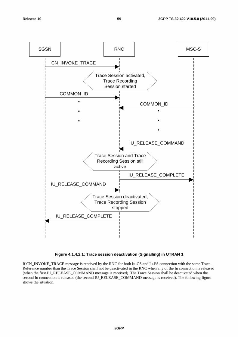
3GPP
3GPP TS 32.422 V10.5.0 (2011-09) 59 Release 10
SGSN RNC MSC-S
CN_INVOKE_TRACE
Trace Session activated,
Trace Recording
Session started
.
.
.
.
.
.
COMMON_ID
COMMON_ID
Trace Session and Trace
Recording Session still
active
Trace Session deactivated,
Trace Recording Session
stopped
IU_RELEASE_COMMAND
IU_RELEASE_COMPLETE
IU_RELEASE_COMMAND
IU_RELEASE_COMPLETE
Figure 4.1.4.2.1: Trace session deactivation (Signalling) in UTRAN 1
If CN_INVOKE_TRACE message is received by the RNC for both Iu-CS and Iu-PS connection with the same Trace
Reference number than the Trace Session shall not be deactivated in the RNC when any of the Iu connection is released
(when the first IU_RELEASE_COMMAND message is received). The Trace Session shall be deactivated when the
second Iu connection is released (the second IU_RELEASE_COMMAND message is received). The following figure
shows the situation.

3GPP
3GPP TS 32.422 V10.5.0 (2011-09) 60 Release 10
SGSN RNC MSC-S
CN_INVOKE_TRACE
Trace Reference=x
Trace Session activated,
Trace Recording
Session started
.
.
.
.
.
.
COMMON_ID
COMMON_ID
Trace Session and Trace
Recording Session still
active
Trace Session deactivated,
Trace Recording Session
stopped
IU_RELEASE_COMMAND
IU_RELEASE_COMPLETE
IU_RELEASE_COMMAND
IU_RELEASE_COMPLETE
Trace Session and Trace
Recording Session is still
active (same)
CN_INVOKE_TRACE
Trace Reference=x
Figure 4.1.4.2.2: Trace session deactivation (Signalling) in UTRAN 2
3GPP
3GPP TS 32.422 V10.5.0 (2011-09) 61 Release 10
Interaction with Soft-handover
The Trace Session should be deactivated in a Drift RNC when the DRNC receives the IUR_DEACTIVATE_TRACE
message or the Iur connection is released.
When an RNC deactivates a Trace Session the Trace Recording Session shall also be stopped at the same time.
NOTE: In RNC the Trace Session and the Trace Recording Session always the same.
4.1.4.3 PS Domain deactivation mechanisms
When an HSS receives a Trace Session deactivation from the Management System it shall send a
MAP_DEACTIVATE_TRACE_MODE message to the SGSN.
When the SGSN receives a MAP_DEACTIVATE_TRACE_MODE message it shall deactivate the Trace Session
identified by the Trace reference received in the MAP_DEACTIVATE_TRACE_MODE message.
If a Trace Recording Session is active at the time of receiving a deactivation message (in SGSN it is the MAP-
DEACTIVATE_TRACE_MODE, in GGSN it is the GTP Update PDP Context Request or the Update MBMS Context
Request, in BM-SC it is the Diameter Gmb STR message), the SGSN and/or the GGSN and/or the BM-SC may
choose to continue the Trace Recording Session till it ends gracefully or may stop it immediately. In all cases, the
SGSN/GGSN/BM-SC shall deactivate the requested Trace Session immediately at the end of the Trace Recording
Session. When the SGSN deactivates the Trace Session, it shall delete all trace control and configuration parameters
associated with the corresponding Trace Session.
If SGSN deactivates the Trace Session during the Trace Recording Session, the SGSN should deactivate the trace to the
RNC by using the CN_DEACTIVATE_TRACE RANAP message and should deactivate the trace to the GGSN by
sending the GTP Update PDP Context Request or the Update MBMS Context Request message with Trace Activity
Control set to Trace Deactivation.
If the GGSN deactivates the Trace Session during the Trace Recording Session, the GGSN should deactivate the trace
to the BM-SC (by sending a Diameter Gmb STR message).
4.1.4.4 CS Domain deactivation mechanisms
When an HSS receives Trace Session deactivation from the Management System it shall send a
MAP_DEACTIVATE_TRACE_MODE message to the MSC Server.
When the MSC Server receives a MAP_DEACTIVATE_TRACE_MODE message it shall deactivate the Trace Session
identified by the Trace reference received in the MAP_DEACTIVATE_TRACE_MODE message.
If a Trace Recording Session is active at the time of receiving a MAP_DEACTIVATE_TRACE_MODE message from
the HSS, the MSC Server may choose to continue the Trace Recording Session till it ends gracefully or may stop it
immediately. In all cases, the MSC Server shall deactivate the requested Trace Session immediately at the end of the
Trace Recording Session. When the MSC Server deactivates the Trace Session it shall delete all trace control and
configuration parameters associated with the corresponding Trace Session. .
If MSC Server deactivates the Trace Session during a Trace Recording Session, it should deactivate the trace to the
RNC by sending the CN_DEACTIVATE_TRACE RANAP message and should deactivate the trace to the MGW.
4.1.4.5 Void
4.1.4.6 Service Level Trace in IMS deactivation mechanisms
4.1.4.6.1 General
When an IMS NE (i.e. S/I/P-CSCF, AS, HSS, MRF, MGCF, BGCF) receives Trace Session deactivation the Trace
Session, as identified by the Trace Reference, shall be deactivated.
If a Trace Recording Session(s) within the Trace session is active at the time of receiving a Trace Session deactivation,
the IMS NE may stop the trace recording session(s) immediately or it may choose to continue the Trace Recording
Session(s) till the session(s) ends gracefully (e.g. the SIP session ends after a specific period of time, or upon
completion of a SIP session and the reception of a SIP BYE).

3GPP
3GPP TS 32.422 V10.5.0 (2011-09) 62 Release 10
In all cases, the IMS NE shall deactivate the requested Trace Session immediately at the end of the Trace Recording
Session(s). When the IMS NE deactivates the Trace Session, it shall delete all associated trace control and configuration
parameters associated with that Trace Session.
4.1.4.6.2 Trace session deactivation at an IMS NE
4.1.4.6.2.1 Trace session deactivation propagated by EM
Trace Session deactivation may be initiated from the Core Network EM only [EM (UE), and EM (HSS)]. The same EM
that initiated Trace Session activation shall initiate a Trace Session deactivation in the same Network Element (NE).
When Trace Session deactivation is required for a registered home subscriber in the home IM CN SS, Trace Session
deactivation shall go to the UE and the HSS. The HSS shall propagate the Trace Session deactivation to the S-CSCF, I-
CSCF, and the AS. The S-CSCF and I-CSCF shall propagate the Trace Session deactivation to the P-CSCF. The Trace
Session deactivation shall be propagated to the MRF, MGCF and BGCF via the S-CSCF.
When Trace deactivation is required for a registered home subscriber in a visited IM CN SS, Trace Session deactivation
shall go to the UE and the HSS. The HSS shall propagate the Trace Session deactivation to the S-CSCF, I-CSCF and
the AS.
Depending on whether the I-CSCF had previously propagated a Trace Session Activation to the P-CSCF serving the UE
(see subclause 4.1.2.9.2) where Trace is to be initiated the I-CSCF may propagate the Trace Session deactivation to the
P-CSCF.
4.1.4.6.2.2 Trace session deactivation following a Triggering event
An Active Trace Session may be deactivated at an IMS NE following the detection of a Stop Triggering Event, e.g.
Trace Session expiry time.
In the case where there is one or more active Trace Recording Sessions, the IMS NE shall deactivate the Trace Session
immediately following the detection of a Stop Triggering Event associated for each of the Trace Recording Session(s),
e.g. following the detection of SIP final response or a SIP Request Failure
When the IMS NE deactivates the Trace Session Stop Triggering Event, it shall delete all associated trace control and
configuration parameters associated with that Trace Session.
4.1.4.6.2.3 Trace session deactivation initiated directly by an EM
When required, an active Trace Session at an IMS NE may be deactivated directly by its EM. The Management based
Trace Session deactivation mechanism (see clause 4.1.1) shall be used for this purpose.
4.1.4.6.3 Trace session deactivation at the UE
The EM (UE) and the interactions between the EM (UE) and the UE shall be achieved using OMA Device Management
[18].
Figure 4.1.4.6.3.1 illustrates the sending of Trace Session Deactivation from the Device Management Server (DMS) to
a UE.
Editor’s note: The exact OMA Device Management enabler is FFS.

3GPP
3GPP TS 32.422 V10.5.0 (2011-09) 63 Release 10
2. UE Management operation
(incl. Trace Session Deactivation)
Trace Session
activated
1. Management session established
DMS UE
3.Trace Session
deactivated
Figure 4.1.4.6.3.1: Trace session deactivation at a UE
Trace Session deactivation shall be initiated from the Device Management Server (DMS). The same DMS that initiated
Trace Session activation shall initiate a Trace Session deactivation in the same UE (Step 1).
When a UE receives Trace Session Deactivation as part of the received management operation from its DMS (Step 2) it
may deactivate the Trace Session (Step 3).
If a Trace Recording Session(s) within the Trace session is active at the time of receiving a Trace Session deactivation,
the UE may stop the trace recording session(s) immediately (see note), or it may choose to continue the Trace
Recording Session(s) until the session(s) end gracefully (e.g. the SIP session ends after a specific period of time, or
upon completion of a SIP session and the reception of a SIP BYE).
NOTE: When the Trace session is stopped the UE may deactivate or delete its management operation.
4.1.4.7 EPC deactivation mechanisms
When an HSS receives a Trace Session Deactivation from the Management System it shall send an S6a-Delete
Subscriber Data Request message to the MME at which the UE is currently registered if MME is included in the NE
types for Tracing, via the S6a interface to remove the “trace data” from subscription data (see 3GPP TS 29.272[26]).
The HSS shall deactivate trace if trace is active at the HSS.
When the MME receives the S6a-Delete Subscriber Data Request message to remove the “trace data” from subscription
data (see 3GPP TS 29.272 [26]) or the Trace Session is deactivated directly from the EM it shall deactivate the Trace
Session identified by the Trace Reference.
If the UE was registered to the HSS by an MME via the S6a interface, (.e. the user is attached to a 3GPP access
network), the Trace Session shall be deactivated to the MME via the S6a interface.
If the user was registered by a AAA server via the SWx interface (i.e. the user is attached to a non-3GPP network) the
HSS shall send the Trace Session deactivation request with a push profile request.
The AAA server shall examine the received user profile and if it detects that the Trace Session shall be deactivated, it
shall initiate a re-authorization procedure towards the PDN GW. The Trace Session is deactivated in the PDN GW by
using this re-authorization procedure.

3GPP
3GPP TS 32.422 V10.5.0 (2011-09) 64 Release 10
When the PDN GW receives the updated authorization data with trace information that represents Trace Session
deactivation request, it shall deactivate the Trace Session identified by the Trace Reference.
The following figure illustrates the Trace Session deactivation when the user is attached to a non-3GPP access network
for DSMIPv6 on S2c or PMIP on S2a/S2b.
Figure 4.1.4.7.1: Trace Session deactivation in case UE attached from non-3GPP access network for DSMIPv6 on S2c or PMIP on S2a/S2b
If the user was registered by a AAA server via the SWx interface (i.e. the user is attached to a non-3GPP network) the
HSS shall send the Trace Session deactivation request with a push profile request.
The AAA server shall examine the received user profile and if it detects that the Trace Session shall be deactivated, it
shall initiate a re-authorization procedure towards the ePDG.
The ePDG shall examine the received information from the AAA and if it detects that the Trace Session shall be
deactivated (see 3GPP TS 29.273 [22]), it shall initiate a trace deactivation procedure towards the PDN GW (see
3GPP TS 29.274 [34]).
When the PDN GW receives the data with trace information that represents Trace Session deactivation request, it shall
deactivate the Trace Session identified by the Trace Reference.

3GPP
3GPP TS 32.422 V10.5.0 (2011-09) 65 Release 10
ePDG PDN GW3GPP AAA
serverHSS
Authorization Request
Push Profile request (Trace Info)
:
EM
Trace Session Deactivation
Authorization Response(Includes Trace information)
Trace activated
:
Trace deactivated
Trace Session
deactivation
Re-authorization Request
Re-authorization Response
Figure 4.1.4.7.2 : Trace Session deactivation in case UE attached from non-3GPP access network for GTP based S2b interface
When the MME receives the S6a-Delete Subscriber Data Request message to remove the “trace data” from subscription
data (see 3GPP TS 29.272 [26]) or the Trace Session is deactivated directly from the EM it shall deactivate the Trace
Session identified by the Trace Reference.
If a Trace Recording Session is active at the time of receiving a deactivation message, the MME may choose to
continue the Trace Recording Session until it ends gracefully or may stop it immediately. In all cases, the MME shall
deactivate the requested Trace Session immediately at the end of the Trace Recording Session. When the MME
deactivates the Trace Session, it shall delete all trace control and configuration parameters associated with the
corresponding Trace Session.
If MME deactivates the Trace Session during the Trace Recording Session, the MME should deactivate the trace at the
eNB by sending the S1-Deactivate Trace message to the eNodeB via the S1 interface and should deactivate the trace at
the SGW by sending an S11-Trace Session Deactivation message to the SGW via the S11 interface. The message sent
by MME shall include the Trace Reference to identify the Trace Session that is to be deactivated.
When SGW receives an S11-Trace Session Deactivation message from the MME, the SGW may choose to continue the
Trace Recording Session until it ends gracefully or may stop it immediately. In all cases, the SGW shall deactivate the
requested Trace Session immediately at the end of the Trace Recording Session. If SGW deactivates the Trace Session
during the Trace Recording Session, the SGW should deactivate the trace at the PDN GW by sending the S5-Trace
Session Deactivation message to the PGW via the GTP based S5 interface. In case of PMIP based S5 interface the SGW
should deactivate the trace to the PDN GW using PCC signalling, i.e. by sending a Trace Deactivation message to the
PCRF and PCRF forwards the trace deactivation message to the PDN GW [29].When the SGW deactivates the Trace
Session, it shall delete all trace control and configuration parameters associated with the corresponding Trace Session.
When PGW receives an S5-Trace Session Deactivation message from the SGW, or S2b-Trace Session Deactivation
message from the ePDG, or it receives the Trace Session Deactivation message from PCRF in case of PMIP based S5,
the PDN GW may choose to continue the Trace Recording Session until it ends gracefully or may stop it immediately.
In all cases, the PDN GW shall deactivate the requested Trace Session immediately at the end of the Trace Recording
Session. When the PDN GW deactivates the Trace Session, it shall delete all trace control and configuration parameters
associated with the corresponding Trace Session.

3GPP
3GPP TS 32.422 V10.5.0 (2011-09) 66 Release 10
When a Trace Session Deactivation message is sent on any interface the Trace Reference that identifies the Trace
Session shall be included to the Trace Session Deactivation message.
4.1.4.8 E-UTRAN deactivation mechanisms
When eNB receives the S1- Deactivate Trace message it shall deactivate the Trace Session for the indicated Trace
Reference.
If the S1 connection is released that is related to the traced subscriber or equipment, eNB shall also deactivate the Trace
Session.
4.1.4.9 EPC deactivation mechanisms for MDT
When the MME receives a Trace Session Deactivation request for an MDT Trace Session of a UE, it shall act according
to the following.
In case of an immediate MDT trace session and the UE being in connected mode, the MME shall send trace session
deactivation toward the eNodeB. The eNodeB shall deactivate the corresponding MDT RRC measurements in the UE
and shall discard the given trace session context.
In case of an immediate MDT trace session and the UE being in idle mode, the MME shall silently discard the stored
trace session context.
Note: Signaling based deactivation does not apply for logged MDT trace sessions, the logged MDT trace session
terminates when logging duration expires.
4.1.4.10 Deactivation mechanisms at UE for MDT
The UE shall discard a logged MDT trace session when logging duration expires and shall indicate the availability of
logged measurement results to the network next time it enters connected mode.
4.1.5 MDT Trace selection conditions
In Immediate MDT, both in case of signalling based and management based MDT trace activation, it is always the
network that evaluates all selection conditions for activating the MDT measurements and deactivating the MDT
measurements (this evaluation is done continuously during the selected call session). The network activates and
deactivates the MDT measurements toward the UE accordingly via RRC.
In Logged MDT, the network configures UEs for MDT tracing that are eligible based on the specified selection criteria.
If area based condition is specified in the trace configuration, it is sent to the UE at configuration time and the UE will
evaluate the area condition as it moves in the network in idle mode.
Immediate and Logged MDT measurements shall always be configured as separate trace sessions.
In cases of overlapping MDT configuration request the signaling based request shall override the management based
request. For logged MDT, prior to re configuring, the eNB shall retrieve the MDT logs from the UE.

3GPP
3GPP TS 32.422 V10.5.0 (2011-09) 67 Release 10
4.2 Trace recording/UE measurements session Start / Stop triggering
4.2.1 General
Editor's Note: For further study.
The Trace Session activation contains the triggering events parameter. The actual start/stop triggering events
corresponding to the values of the triggering events parameter are defined in triggering events tables in sub-clause 5.1 in
the present document.
If the NE failed to start the Trace Recording Session, a Trace failure notification shall be sent to the TCE, and the Trace
failure notification has the the same parameters as the notification notifyTraceRecordingSessionFailure
defined in 3GPP TS 32.442[24], the Trace failure notification file XML schema is defined in Annex A.
4.2.2 Starting a trace recording session - management based
4.2.2.1 UTRAN starting mechanisms
In an RNC, a Trace Recording Session should start after the reception of the CN_INVOKE_TRACE message from the
CN and if some activities have been started on the interfaces that have been requested to be traced. The RNC shall
record those signalling messages in the interfaces that are defined in the list of interfaces parameter. Trace depth defines
whether entire signalling messages or just some IEs needs to be recorded.
The RNC may not start a Trace Recording Session if there are insufficient resources available for the recording.
When RNC starts a Trace Recording Session it shall assign a Trace Recording Session Reference for the Trace
Recording Session.
4.2.2.2 PS Domain starting mechanisms
In a SGSN/GGSN/BM-SC, a Trace Recording Session should start after the reception of a Trace Session Activation
from EM and if any of the defined start triggering events occur. During the Trace Recording Session, the
SGSN/GGSN/BM-SC shall record those signalling messages in the interfaces that are defined in the list of interfaces
parameter. The Trace Depth parameter defines whether entire signalling messages or just some IEs need to be recorded.
The IMSI and IMEISV shall be available in the SGSN, in the GGSN and in the BM-SC for at least those connections
which shall be traced.
The SGSN/GGSN/BM-SC may not start a Trace Recording Session if there are insufficient resources available for the
recording.
If the SGSN/GGSN/BM-SC receives the Trace Session Activation during an established session (e.g. during an active
PDP context or an active MBMS context), it may start the Trace Recording Session immediately. However, if any of the
start triggering events occur in the SGSN/GGSN/BM-SC after receiving the Trace Session Activation, it shall start the
Trace Recording Session.
When a Trace Recording Session is started, the SGSN/GGSN/BM-SC shall assign a Trace Recording Session
Reference for the Trace Recording Session.
4.2.2.3 CS Domain starting mechanisms
In a MSC Server, a Trace Recording Session shall start after the reception of a Trace Session Activation from EM and if
any of the defined start triggering events occur. During the Trace Recording Session, the MSC Server shall record those
signalling messages in the interfaces that are defined in the list of interfaces parameter. The Trace Depth parameter
defines whether entire signalling messages or just some IEs needs to be recorded.
The IMSI and the IMEISV shall be available in the MSC Server for at least those connections which shall be traced.
The MSC Server may not start a Trace Recording Session if there are insufficient resources available for the recording.

3GPP
3GPP TS 32.422 V10.5.0 (2011-09) 68 Release 10
If the MSC Server receives the Trace Session Activation during an established call, it may start the Trace Recording
Session immediately. However, if any of the start triggering events occurs in MSC Server after receiving the Trace
Session Activation, it shall start the Trace Recording Session.
When a Trace Recording Session is started, the MSC Server shall assign a Trace Recording Session Reference for the
Trace Recording Session.
4.2.2.4 IP Multimedia Subsystem starting mechanisms
Editor's Note: For further study.
4.2.2.5 E-UTRAN starting mechanism
In E-UTRAN, after the Cell Traffic Trace has been activated in the monitored cell(s), the eNodeB shall start a Trace
Recording Session for new call(s)/session(s) and for already existing call(s)/session(s) (events for existing
call(s)/session(s) are not required to be recorded prior to the activation of the cell traffic trace). When the eNodeB starts
a Trace Recording Session it shall allocate a Trace Recording Session Reference for the given call or session. The
eNodeB shall send the allocated Trace Recording Session Reference, and the Trace Reference and the Trace Collection
Entity address in the CELL TRAFFIC TRACE message to the MME via the S1 connection.
When MME receives this new S1 signalling message containing the Trace Recording Session Reference and Trace
Reference, the MME shall look up the IMSI/IMEI(SV) of the given call from its database and shall send the
IMSI/IMEI(SV) numbers together with the Trace Recording Session Reference and Trace Reference to the Trace
Collection Entity.
The format of the file sent to the TCE from the MME is defined in 3GPP TS 32.423 A.2.2.
The figure 4.2.2.5.1 illustrates the procedure

3GPP
3GPP TS 32.422 V10.5.0 (2011-09) 69 Release 10
EM eNodeB MME Trace Collection Enity
Trace Session Activation
Starting Trace Session
NAS Service Request
S1: Cell Trace Notification
UE
Trace Reference,
E-UTRAN Cell list
Starting Trace Recording
Session and allocation
Trace Recording Session
Reference
Call Setup
Trace Reference,
Trace Recording Session Reference
Trace Record
Call Setup
Trace Recording Session
stops
Searching for IMSI,
IMEI(SV)
Trace Record
Trace Reference,
Trace Recording Session Reference,
IMSI, IMEI(SV)
Figure 4.2.2.5.1

3GPP
3GPP TS 32.422 V10.5.0 (2011-09) 70 Release 10
4.2.2.6 EPC Domain starting mechanisms
In a MME, SGW or PGW, a Trace Recording Session should start after the reception of a Trace Session Activation
from EM and if any of the defined start triggering events occur. During the Trace Recording Session, the MME, SGW
or PGW shall record those signalling messages in the interfaces that are defined in the list of interfaces parameter. The
Trace Depth parameter defines whether entire signalling messages or just some IEs need to be recorded.
The IMSI and IMEISV shall be available in the MME and in the SGW for at least those connections which shall be
traced.
The MME, SGW or PGW may not start a Trace Recording Session if there are insufficient resources available for the
recording.
If the MME, SGW or PGW receives the Trace Session Activation during an established session (e.g. during an active
PDP context), it may start the Trace Recording Session immediately. However, if any of the start triggering events
occur in the MME, SGW or PGW after receiving the Trace Session Activation, it shall start the Trace Recording
Session.
When a Trace Recording Session is started, the MME, SGW or PGW shall assign a Trace Recording Session Reference
for the Trace Recording Session.
4.2.2.7 E-UTRAN starting mechanisms for MDT
A trace recording session of immediate MDT or logged MDT shall be started in the eNodeB for each selected UE that
satisfy the MDT UE selection criteria (i.e., capability condition), provided that a cell trace session for immediate MDT
or logged MDT has been activated in the eNodeB from EM for the given cell(s) before.
The eNodeB shall configure the corresponding MDT RRC measurements at the selected UE.
4.2.2.8 Starting mechanisms at UE for MDT
There is no starting mechanism at the UE for MDT trace recording sessions. The UE shall execute the received MDT
measurement configuration. In case of logged MDT, the UE shall store the trace recording session parameters as
received from the eNodeB.
3GPP
3GPP TS 32.422 V10.5.0 (2011-09) 71 Release 10
4.2.3 Starting a trace recording session - signalling based
4.2.3.1 UTRAN starting mechanisms
In an RNC the Trace Recording Session will always be the same as the Trace Session as no triggering events are
defined in UTRAN. Therefore a Trace Recording Session should be started in an SRNC when the SRNC receives the
CN_INVOKE_TRACE message from the Core Network and if some activities have been started on the interfaces that
have been requested to be traced.
The CN_INVOKE_TRACE message that is received from the Core Network (MSC Server or SGSN) contains the
following information:
Trace Reference
UE identity (IMSI or IMEI(SV)
Trace Recording Session Reference
Trace Depth
List of interfaces for RNC
Job type
Area scope
List of measurements
Reporting Trigger
Report Interval
Report Amount
Event Threshold
Logging Interval
Logging Duration
Note that at the same time not all of the parameters can be present. The conditions which parameters shall be
present is described in section 5.10 of the present document.
If the Job type parameter indicates MDT (e.g. Immediate or logged MDT is required) in the CN_INVOKE_TRACE
message the RNC shall also configure MDT to the UE. The detailed mechanism of the MDT configuration to the UE is
defined in TS 37.320 [30] and TS 25.331 [31].
The RNC shall send the following parameters to the UE in case of Logged MDT:
Trace Reference
Trace Recording Session Reference
Area scope
TCE Id (The value signalled as IP address of TCE is mapped to a TCE Id, using a configured mapping in the
RNC).
Logging Interval
Logging Duration
In case of Immediate MDT the RNC shall send the following parameters to the UE:
List of measurements

3GPP
3GPP TS 32.422 V10.5.0 (2011-09) 72 Release 10
Reporting Trigger
Report Interval
Report Amount
Event Threshold
Note that at the same time not all of the parameters can be present. The conditions which parameters shall be
present is described in section 5.10 of the present document.
If the SRNC does not have enough resources it may not start a Trace Recording Session.
The Trace Recording Session Reference shall be the same as received in the CN_INVOKE_TRACE message.
In a DRNC the Trace Recording Session should be started when the DRNC receives the IUR_INVOKE_TRACE
message. If the DRNC does not have enough resources it may not start a Trace Recording Session.
The Trace Session is activated to the RNC by sending a CN_INVOKE_TRACE message from the CN (MSC Server or
SGSN). When RNC receives the CN_INVOKE_TRACE message it should immediately start a Trace Session and a
Trace Recording Session according to the trace control and configuration parameters received in the
CN_INVOKE_TRACE message.
If there are not enough resources in RNC to start a Trace Recording Session, the RNC may reject to start a Trace
Recording Session. However the RNC shall start the Trace Session. Session and if MDT activation is requested shall
activate the MDT to the UE.
When SRNC/DRNC receives the trace control and configuration parameters:
- If the Trace Reference is the same as an existing Trace Session for the same subscriber or equipment in
SRNC/DRNC, the SRNC/DRNC shall not activate a new Trace Session and the existing Trace Session will not
be impacted;
- If the Trace Recording Session Reference is the same as an existing Trace Recording Session in the existing
Trace Session having the same Trace Reference, the SRNC/DRNC shall not start a new Trace Recording
Session;
- If the trace control and configuration parameters are received from the same CN domain (CS/PS) as the existing
Trace Recording Session(s) if any, and the Trace Recording Session Reference is not the same as any existing
Trace Recording Session(s) in the existing Trace Session having the same Trace Reference, the SRNC/DRNC
shall start a new Trace Recording Session;
- If the trace control and configuration parameters are received from different CN domain (CS/PS) as the existing
Trace Recording Session(s) if any (i.e. the RNC has simultaneoud CS and PS connection and
CN_INVOKE_TRACE is received from both connection), regardless of the Trace Recording Session Reference
is the same or not as any existing Trace Recording Session(s) in the existing Trace Session having the same
Trace Reference, the SRNC shall not start a new Trace Recording Session;
- If the Trace Reference is the same as an existing Trace Session for different subscriber(s) or equipment(s) in
SRNC/DRNC, the SRNC /DRNC shall not activate a new Trace Session, and the SRNC/DRNC shall not start a
new Trace Recording Session.
The following figure shows an example for a CS call how the Trace Session is activated to RNC. In the example it is
assumed that there is no PS connection at all during the CS call.

3GPP
3GPP TS 32.422 V10.5.0 (2011-09) 73 Release 10
MSC-S RNC UE
Trace Session
started
Trace Session and
Trace Recording
Session started
Trace Session and
Trace Recording
Session stopped
CM_Service_Request
CN_Invoke_Trace
Setup
Iu Release Command
Iu Release Complete
.
.
.
Figure 4.2.3.1.1: Starting a Trace Recording Session (Signalling) in UTRAN
Interaction with soft-handovers
If the subscriber or equipment, which is traced, makes a soft handover the SRNC should propagate the trace control and
configuration parameters (including MDT specific parameters if they are available) further to the DRNC by using the
IUR_INVOKE_TRACE message. When the DRNC receives the IUR_INVOKE_TRACE message it should
immediately start a Trace Session and a Trace Recording Session according to the trace control and configuration
parameters received in the IUR_INVOKE_TRACE message.
If there are insufficient resources in the DRNC, the DRNC may not start a Trace Recording Session.
The Trace Recording Session Reference sent by the SRNC to the DRNC shall be the same what SRNC has received in
the CN_INVOKE_TRACE message from the CN.
Interaction with Relocation
If the tracing shall continue also after the relocation has been performed, the CN Invoke Trace procedure shall be re-
initiated from the CN towards the future SRNC after the Relocation Resource Allocation procedure has been executed
successfully.

3GPP
3GPP TS 32.422 V10.5.0 (2011-09) 74 Release 10
4.2.3.2 PS Domain starting mechanisms
In SGSN/GGSN/BM-SC a Trace Recording Session should start after the reception of a Trace Session Activation
message (in SGSN it is the MAP-ACTIVATE_TRACE_MODE, in GGSN it is the GTP-Create PDP Context request or
Update PDP Context request, in BM-SC it is the Diameter Gmb AAR message) and if any of the defined start
triggering events occur. During the Trace Recording Session, the SGSN/GGSN/BM-SC shall record the signalling
messages in the interfaces that are defined in the list of interfaces parameter. The Trace Depth parameter defines
whether entire signalling messages or just some IEs need to be recorded.
The SGSN/GGSN/BM-SC may not start a Trace Recording Session if there are insufficient resources available for the
recording.
In case of an established session, the SGSN may start the Trace Recording Session immediately after the reception of
the Trace Session Activation message. However, if any of the start triggering events occurs in SGSN after receiving the
Trace Session activation message, it shall start the Trace Recording.
When a Trace Recording Session is started in SGSN, it shall assign a Trace Recording Session Reference for the Trace
Recording Session. When the SGSN propagates the Trace control and configuration parameters to GGSN or to UTRAN
(I.e. activates a Trace Session in GGSN/UTRAN), it shall include the assigned Trace Recording Session Reference in
the Trace Session Activation message. When an SGSN starts a Trace Recording Session and the list of NE types
parameter requires GGSN tracing, it shall send the GTP- Update PDP Context Request or Create PDP Context Request
message for activating the Trace Session to GGSN. When a GGSN starts a Trace Recording Session and the list of NE
types parameter requires BM-SC tracing, it shall send a Diameter Gmb AAR message to the BM-SC in order to activate
a Trace Session in the BM-SC. Also, when an SGSN starts a Trace Recording Session and the list of NE types
parameter requires RNC tracing, it shall send the CN_INVOKE_TRACE message to the RNC in order to activate a
Trace Session in RNC. In both cases the Trace Session and the Trace Recording Session in the receiving NE should
start at the same time.
In case of SRNS relocation the SGSN shall send the CN_INVOKE_TRACE message to the new SRNC after the
successful Relocation Resource Allocation procedure.
SGSN has to find the identity of the mobile before it activates a Trace Session towards other NE. The IMEI(SV) can be
got from the Mobile by using the Identification procedure on the Iu interface.
When the SGSN sends the Trace Session activation (CN_INVOKE_TRACE) message to RNC it shall include the
following parameters to the message:
IMSI or IMEI (SV) (M).
Trace reference (M).
Trace Recording Session Reference (M).
Trace Depth (M).
List of interfaces (O).

3GPP
3GPP TS 32.422 V10.5.0 (2011-09) 75 Release 10
4.2.3.3 CS Domain starting mechanisms
In MSC Server/MGW a Trace Recording Session should start after the reception of a Trace Session Activation message
(MAP-ACTIVATE TRACE MODE in MSC Server and ADD/MOD command with Trace package in MGW) and if
any of the defined start triggering events occur. During the Trace Recording Session the MSC Server/MGW shall
record the signalling messages in the interfaces that are defined in the list of interfaces parameter. The Trace Depth
parameter defines whether entire signalling messages or just some IEs need to be recorded.
The MSC Server may not start a Trace Recording Session if there are insufficient resources available for the recording.
In case of an established call, the MSC Server may start the Trace Recording Session immediately after the reception of
the MAP-ACTIVATE_TRACE_MODE message. However, if any of the start triggering events occur in the MSC
Server after receiving the Trace Session activation message, it shall start the Trace Recording Session.
When a Trace Recording Session is started in MSC Server, it shall assign a Trace Recording Session Reference for the
Trace Recording Session. When the MSC Server propagates the Trace control and configuration parameters to MGW or
to UTRAN (I.e. activates a Trace Session in MGW/UTRAN) it shall include the assigned Trace Recording Session
Reference in the Trace Session Activation message.
When an MSC Server starts a Trace Recording Session and the list of NE types parameter requires MGW tracing, it
shall send the ADD/MOD command with trace package to MGW in order to activate the trace in MGW. Also, when an
MSC Server starts a Trace Recording Session and the list of NE types parameter requires RNC tracing, it shall send the
CN_INVOKE_TRACE message to the RNC. In both cases the Trace Session and the Trace Recording Session in the
receiving NE should start at the same time.
MSC Server has to find the identity of the mobile before it activates a Trace Session towards other NE. The IMEI(SV)
can be got from the Mobile by using the Identification procedure on the Iu interface.
In case of SRNS relocation the MSC Server shall send the CN_INVOKE_TRACE message to the new SRNC after the
successful Relocation Resource Allocation procedure. The following figure shows an example how the Trace Session is
activated with CN_INVOKE_TRACE message in case of relocation.

3GPP
3GPP TS 32.422 V10.5.0 (2011-09) 76 Release 10
MSC-Sold S-RNC new S-RNC
Trace Session and
Trace Recording
Session started
Trace Session and
Trace Recording
Session stopped
Iu-Relocation-Required
Iu-Relocation-Request
Iu-Relocation-Request-Ack
CN-Invoke-Trace
Iu-Relocation-Command
Iu-Relocation-Detect
Iu-Relocation-Complete
Iu-Release-Command
Iu-Release-Complete
Trace Session and
Trace Recording
Session started
Figure 4.2.3.3.1: Starting a Trace Recording Session (Signalling) in CS Domain
When the new SRNC receives the CN_INVOKE_TRACE message it should start immediately a Trace Session and a
Trace Recording session according to the trace control and configuration parameters received in the
CN_INVOKE_TRACE message. The Trace Session shall automatically be deactivated in the old RNC when the Iu
connection is released.
When the MSC Server sends the Trace Session activation (CN_INVOKE_TRACE) message to RNC it shall include the
following parameters to the message:
IMSI or IMEI (SV) (M).
Trace reference (M).
Trace Recording Session Reference (M).
Trace Depth (M).
List of interfaces to trace (O).
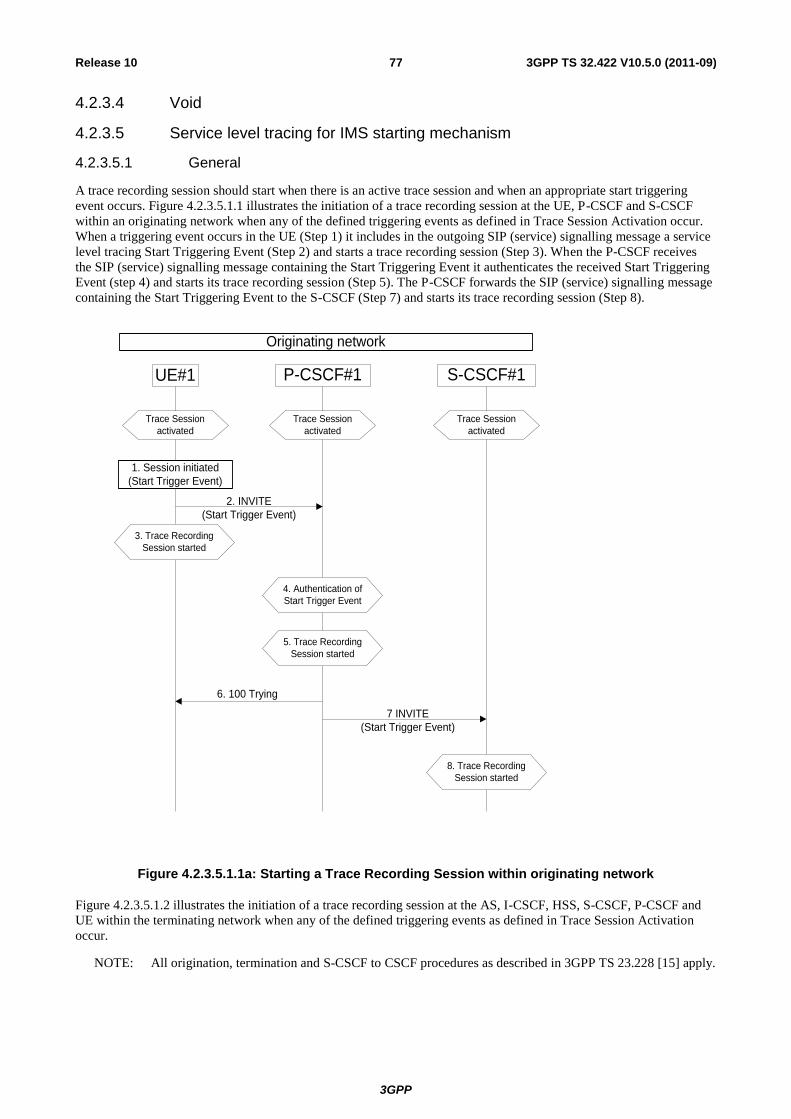
3GPP
3GPP TS 32.422 V10.5.0 (2011-09) 77 Release 10
4.2.3.4 Void
4.2.3.5 Service level tracing for IMS starting mechanism
4.2.3.5.1 General
A trace recording session should start when there is an active trace session and when an appropriate start triggering
event occurs. Figure 4.2.3.5.1.1 illustrates the initiation of a trace recording session at the UE, P-CSCF and S-CSCF
within an originating network when any of the defined triggering events as defined in Trace Session Activation occur.
When a triggering event occurs in the UE (Step 1) it includes in the outgoing SIP (service) signalling message a service
level tracing Start Triggering Event (Step 2) and starts a trace recording session (Step 3). When the P-CSCF receives
the SIP (service) signalling message containing the Start Triggering Event it authenticates the received Start Triggering
Event (step 4) and starts its trace recording session (Step 5). The P-CSCF forwards the SIP (service) signalling message
containing the Start Triggering Event to the S-CSCF (Step 7) and starts its trace recording session (Step 8).
UE#1 P-CSCF#1 S-CSCF#1
6. 100 Trying
2. INVITE
(Start Trigger Event)
1. Session initiated
(Start Trigger Event)
Trace Session
activated
Trace Session
activated
Trace Session
activated
3. Trace Recording
Session started
7 INVITE
(Start Trigger Event)
5. Trace Recording
Session started
8. Trace Recording
Session started
4. Authentication of
Start Trigger Event
Originating network
Figure 4.2.3.5.1.1a: Starting a Trace Recording Session within originating network
Figure 4.2.3.5.1.2 illustrates the initiation of a trace recording session at the AS, I-CSCF, HSS, S-CSCF, P-CSCF and
UE within the terminating network when any of the defined triggering events as defined in Trace Session Activation
occur.
NOTE: All origination, termination and S-CSCF to CSCF procedures as described in 3GPP TS 23.228 [15] apply.

3GPP
3GPP TS 32.422 V10.5.0 (2011-09) 78 Release 10
UE#2
7. INVITE
(Start Trigger Event)
AS HSSS-CSCF#1 I-CSCF#2 S-CSCF #2
11. INVITE
(Start Trigger Event)
14. INVITE
(Start Trigger Event)
15. INVITE
(Start Trigger Event)
18. Cx User Location Query
(Start Trigger Event)
20. Cx User Location Response
(Start Trigger Event)
21. INVITE
(Start Trigger Event)
P-CSCF#2
30. 183 Session
Progress31. 183 Session
Progress
10. Service control
12. Started Trace
Recording session
8. Started Trace
Recording session
16. Started Trace
Recording session
19. Started Trace
Recording session
22. Started Trace
Recording session
9. 100 Trying
Trace Session activated
13. 100 Trying
24. INVITE
(Start Trigger Event)
17. 100 Trying
23. 100 Trying
25. Started Trace
Recording session26. 100 Trying
28. Started Trace
Recording session
27. INVITE
(Start Trigger Event)
29. 100 Trying
32. 183 Session
Progress33. 183 Session
Progress34. 183 Session
Progress
Originating network Terminating network
Figure 4.2.3.5.1.1b: Starting a Trace Recording Session within terminating network
3GPP
3GPP TS 32.422 V10.5.0 (2011-09) 79 Release 10
When S-CSCF#1 receives the SIP (service) signalling message containing the Service Level Tracing Start Trigger
Event (step 7) it shall start a trace recording session (Step 8). Based on the service control information (step 10) S-
CSCF#1 forwards the SIP (service) signalling message containing the Start Trigger Event to the Application Server
(Step 11).
On reception of the SIP INVITE the Application Server adds, removes, or modifies the header contents contained in the
SIP INVITE (see 3GPP TS 23.218) and proxies the SIP INVITE together with the Start Trigger Event back to S-
CSCF#1 (Step 14). The Application Server also starts a trace recording session (Step 12).
S-CSCF#1 forwards the SIP INVITE containing the service level tracing Start Trigger Event request to I-CSCF#2 (Step
15). At this point the I-CSCF starts a trace recording session Step 16).
I-CSCF#2 initiates a query to the HSS for the current location of the terminating user (UE#2) and includes in the Cx-
User Location procedure the service level tracing Start Trigger Event (Step 20).
When the HSS receives the query for the current location and an associated Start Trigger Event it shall start a trace
recording session (Step 19) and returns to the I-CSCF#2 the address of the current S-CSCF (S-CSCF#2) for the
terminating user and the service level tracing Start Trigger Event (20).
I-CSCF#2 forwards the SIP INVITE containing the Start Trigger Event to the S-CSCF (S-CSCF#2) that will handle the
session termination. When the S-CSCF receives the SIP INVITE containing the Start Trigger Event it starts a trace
recording session (Step 21).
The S-CSCF forwards the SIP INVITE containing the Start Trigger Event to the P-CSCF (P-CSCF#2). When the P-
CSCF receives the SIP INVITE containing the Start Trigger Event it starts a trace recording session (Steps 24 and 25).
The P-CSCF forwards the SIP INVITE containing the Start Trigger Event to the terminating UE (UE#2). When the
terminating UE receives the SIP INVITE containing the Start Trigger Event it starts a trace recording session (Step 28).
The continuation of the termination procedures is as defined in 3GPP TS 23.228 [15].
4.2.3.5.2 Starting mechanism at the UE
For a UE that has an active trace session (see subclause 4.1.2.9.4) one or more trace recording session(s) (e.g. to allow
the tracing for several different simultaneous services) shall be started when any of the defined triggering events occur
at the UE, and when the condition(s) as defined by the trace control and configuration parameters within the received
management operation occur.
Editor’s note: The exact OMA Device Management enabler is FFS.
A Trace recording session(s) may be initiated at an originating UE when:
1) The UE detects the initiation of the specified service to be traced. The service may be initiated either by the
end user or by an application.
The triggering events at a terminating UE include:
1) The UE detects the initiation of the specified service to be traced. The service may be initiated either by the
end user or by an application.
2) The UE detects the reception of an incoming SIP message containg the service level tracing Start Triggering
Event.
A Trace recording session(s) may be initiated at a UE (both originating and terminating) when it detects a start trigger
event initiated directly by the Device Management server for the purpose of allowing not only SIP information related
to the service to be traced, but also information relating to the processes performed by the UE to support the
initialization of the service.
Upon the detection of a triggering event the UE shall include in the appropriate outgoing SIP (service) signalling
message (i.e. the outgoing signalling messages associated with the service to be traced) a service level tracing Start
Triggering Event.
4.2.3.5.3 Starting mechanism at the IMS NE
For an IMS NE (i.e. S/I/P-CSCF, AS, HSS, MRF, MGCF, BGCF) that has an active trace session (see subclause
4.1.2.9) a trace recording session should be started when it receives in an incoming SIP (service) signalling message or

3GPP
3GPP TS 32.422 V10.5.0 (2011-09) 80 Release 10
DIAMETER signalling message containing a service level tracing Start Triggering Event and when the information
contained within the service level tracing Start Triggering Event matches the information received by the IMS NE
during trace session activation. The IMS NE shall also start the recording of signalling messages in the interfaces that
are defined in the list of received interfaces parameter.
An IMS NE (i.e. S/I/P-CSCF, AS, HSS, MRF, MGCF, BGCF) that receives an incoming SIP (service) signalling
message containing a service level tracing Start Triggering Event should forward in an appropriate outgoing SIP
(service) signalling message (i.e. outgoing signalling messages associated with the service being traced) the same
service level tracing Start Triggering Event (i.e. service level tracing Start Triggering Event with the same trace
reference).
When an IMS NE has an active trace session and trace recording session, and when an incoming SIP (service)
signalling message is part of an existing dialog or standalone transaction and contains a service level tracing Start
Trigger Event the IMS NE shall determine that an active Trace Recording Session exists and shall not start a new Trace
Recording Session.
Depending on operator policy, a HSS may forward the service level tracing Start Triggering Event to an external AS
(see 3GPP TS 23.218 [14]). In the case of a terminating session a S-CSCF or I-CSCF may forward the service level
tracing Start Triggering Event to a P-CSCF in a visited IM CN SS. A P-CSCF shall send a service level tracing Start
Triggering Event to a terminating UE.
When a P-CSCF receives a SIP (service) signalling message containing a service level tracing Start Triggering Event
from a UE it shall authenticate the Start Triggering Event by comparing the information contained within the received
service level tracing Start Triggering Event (see subclause 5.2) either against the information it received within the Start
Trace activation message or by requesting information from the I-CSCF or S-CSCF. If the received service level tracing
Start Triggering Event is authenticated by the P-CSCF it should start a trace recording session and shall forward the
service level tracing Start Triggering Event in the appropriate outgoing SIP (service) signalling message.
If the authentication of the incoming service level tracing Start Triggering Event fails the P-CSCF shall not start a trace
recording session and shall not forward the service level tracing Start Triggering Event in any outgoing SIP (service)
signalling message. The P-CSCF should provide an indication to the Management System following the unsuccessful
authentication of the service level tracing Start Triggering Event.
When an IMS NE does not have an active trace session when it receives an incoming SIP (service) signalling message
that contains a service level tracing Start Trigger Event, the IMS NE shall not initiate a Trace Recording Session and
should forward in an appropriate outgoing SIP (service) signalling message the same service level tracing Start Trigger
Event.
4.2.3.5.4 Charging concepts for Service Level Tracing for IMS
Charging for Service Level Tracing for IMS shall be fulfilled using IMS charging mechanism as specified in
TS 32.240 [19] and TS 32.260 [20].
It shall be possible to apply specific tariffs (e.g. zero rating) to the bearer and/or signalling traffic associated with
services subjected to Service Level Tracing for IMS.
As described in subclause 4.2.3.5 an IMS NE that has an active trace session should start a trace recording session when
it detects a service level tracing Start Triggering Event. An IMS NE shall also provide an indication in the generated
charging information that service level tracing has been applied.
4.2.3.6 E-UTRAN starting mechanism
In an eNB the Trace Recording Session will always be the same as the Trace Session as no triggering events are defined
in eNB.
Tracing starts immediately at eNodeB upon reception of the trace control and configuration parameters. The eNodeB
may not start a Trace Recording Session if there are insufficient resources available for the recording, however, the
eNodeB shall store the trace control and configuration parameters, and forward these parameters when the UE
handovers to other eNBs over X2.
The Trace Recording Session shall be started at the eNB when it receives trace control and configuration parameters via
one of the following messages:
1. via an S1-Initial Context Setup Request message from the MME in response to an S1-Initial UE Message

3GPP
3GPP TS 32.422 V10.5.0 (2011-09) 81 Release 10
2. via an S1-Trace Start message from the MME in response to an S1-Initial UE Message or when an established
S1AP connection exists
3. via an S1-Handover Request message from the target MME as part of intra/inter-MME handover procedures
via S1
4. via an X2-Handover Request message from a source eNodeB as part of inter-eNodeB handover procedures via
X2
There can only be one Trace Recording Session Reference per Trace Reference at one given time for a UE trace
session. So there shall be only one TR/TRSR to be propagated during S1 and X2 handover.
If the Trace Reference is the same as an existing Trace Session for the same subscriber or equipment, and the Trace
Recording Session Reference is the same as the existing Trace Recording Session in the existing Trace Session having
the same Trace Reference, the eNB shall not start a new Trace Recording Session and shall continue with the existing
trace session and ignore the second request.
If the Trace Reference is the same as an existing Trace Session for the same subscriber or equipment, and the Trace
Recording Session Reference is not the same as the existing Trace Recording Session in the existing Trace Session
having the same Trace Reference, the eNB shall continue with the existing trace session and ignore the second request.
4.2.3.7 EPC starting mechanisms
In MME/SGW/PGW a Trace Recording Session should start after the reception of a Trace Session Activation message
and if any of the defined start triggering events occur. During the Trace Recording Session, the MME/SGW/PGW shall
record the signalling messages in the interfaces that are defined in the list of interfaces parameter. The Trace Depth
parameter defines whether entire signalling messages or just some IEs need to be recorded.
The MME/SGW/PGW may not start a Trace Recording Session if there are insufficient resources available for the
recording.
In case of an established session, the MME/SGW/PGW may start the Trace Recording Session immediately after the
reception of the trace control and configuration parameters. However, if any of the start triggering events occurs in
MME/SGW/PGW after receiving the trace control and configuration parameters, it shall start the Trace Recording
Session.
In the case of the triggering events come into collision on the same traced UE as defined in 3GPP TS 24.301[33], the
MME shall not start a new Trace Recording Session for the later event(s), and shall use the existing Trace Recording
Session to continuing the trace recording for these events until one stop triggerring event occurs.
When a Trace Recording Session is started in MME, it shall assign a Trace Recording Session Reference for the Trace
Recording Session. When the MME propagates the Trace control and configuration parameters to E-UTRAN (i.e.
activates a Trace Session in eNB), it shall include the assigned Trace Recording Session Reference in the Trace Session
Activation message.
Also, when an MME starts a Trace Recording Session and the list of NE types parameter requires eNB tracing, it shall
propagate the trace control and configuration parameters including the Trace Recording Session Reference via the S1
interface to the eNodeB per one of the following messages:
1. if an S1 connection exists, via the S1-Trace Start message
2. if the S1 connection does not exist, via the S1-Trace Start message prior to S1 connection setup, or via the S1-
Initial Context Setup Request message during S1 connection setup
3. during intra/inter-MME handover over S1, via the S1-Handover Request message
In above cases the Trace Session and the Trace Recording Session in the receiving NE should start at the same time.
NOTE: In case of "UE-Initiated Detach Procedure with UE camping on GERAN/UTRAN and ISR activated /
SGSN-Initiated Detach Procedure with ISR activated",
Trace is not activated in eNB.

3GPP
3GPP TS 32.422 V10.5.0 (2011-09) 82 Release 10
4.2.3.8 EPC starting mechanisms for MDT
In the MME, no trace recording sessions are started for MDT trace sessions. The MME sends the trace session
activation to the eNodeB with parameters as specified in 4.1.2.12.
4.2.3.9 E-UTRAN starting mechanisms for MDT
A trace recording session of either immediate or logged MDT shall be started in the eNodeB for a given UE when a
trace session activation request is received from the MME for the UE and the MDT UE selection conditions are
satisfied for the UE. The eNodeB shall configure the corresponding MDT RRC measurements at the UE. If selection
conditions are not satisfied, the eNodeB shall store the trace control and configuration parameters, and forward these
parameters when the UE handovers to other eNBs over X2 or S1.
If the eNodeB receives a Signalling Based MDT activation request when the UE is served by a cell that is in the
eNodeB but not in the MDT area scope then the eNodeB shall store the MDT configuration and configure the UE when
the UE moves to a cell in the eNodeB (intra eNodeB handover) that satisfies the area scope in the request.
4.2.3.10 Starting mechanisms at UE for MDT
There is no starting mechanism at the UE for MDT trace recording sessions. The UE shall execute the received MDT
measurement configuration. In case of logged MDT, the UE shall store the trace recording session parameters as
received from the eNodeB.

3GPP
3GPP TS 32.422 V10.5.0 (2011-09) 83 Release 10
4.2.4 Stopping a trace recording session - management based
4.2.4.1 UTRAN stopping mechanisms
Editor's Note: The Trace Recording Session in the RNC shall be stopped when the last connection, which belongs to
the traced subscriber/mobile, is released.
4.2.4.2 PS Domain stopping mechanisms
In SGSN, GGSN and BM-SC a Trace Recording Session shall be stopped when any of the defined stop triggering
events occur. If Trace Session deactivation is received during the Trace Recording Session, the SGSN is allowed to
finish tracing of the on-going procedures (e.g. session). In this case the Trace Recording Session shall be stopped
between the reception of the Trace Session deactivation and the appropriate stop-triggering event.
The following figure illustrates the successful case in tracing a PDP context when a Trace Recording Session is stopped.
UE
Figure 4.2.4.2.1: Stopping a Trace Recording Session for a PDP Context (Management Based) - PS domain

3GPP
3GPP TS 32.422 V10.5.0 (2011-09) 84 Release 10
The following figure illustrates the successful case in tracing a MBMS context when a Trace Recording Session is
stopped.
EM of SGSN
EM of BM-SC
EM of GGSN
Trace Session Activation from EM
UE SGSN GGSN BM-SC
Starting a Trace Session
Trace Session Activation from EM
Starting a Trace
Session
Trace Session Activation from EM
Starting a Trace Session SM Request MBMS Context Activation
Starting a Trace
Recording Session
SM Activate MBMS Context Request
Create MBMS Context Request
Starting a Trace
Recording Session
MBMS Authorization Request
Starting a Trace Recording Session
SM Deactivate MBMS Context Request
Stopping a Trace
Recording Session
Delete MBMS Context Request
Deactivation Indication
Stopping a Trace
Recording Session
Deactivation Confirmation
Delete MBMS Context Response
Stopping a Trace
Recording Session
Figure 4.2.4.2.2: Stopping a Trace Recording Session for a MBMS Context (Management Based) - PS domain

3GPP
3GPP TS 32.422 V10.5.0 (2011-09) 85 Release 10
4.2.4.3 CS Domain stopping mechanisms
In MSC Server a Trace Recording Session shall be stopped when any of the defined stop triggering events occur. If
Trace Session deactivation is received during the Trace Recording Session, the MSC Server is allowed to finish tracing
of the on-going procedures (e.g. calls). In this case the Trace Recording Session shall be stopped in MSC Server
between the reception of the Trace Session deactivation and the appropriate stop-triggering event.
The following figure illustrates the successful case in tracing a call and the time of stopping a Trace Recording Session.
UE
Figure 4.2.4.3.1: Stopping a Trace Recording Session (Management Based) - CS domain
4.2.4.4 IP Multimedia Subsystem stopping mechanisms
Editor's Note: For further study.
4.2.4.5 E-UTRAN stopping mechanisms
The Trace Recording Session in the eNodeB shall be stopped when the call/session is ended in the cell under trace or
the call/session is haneded over to another cell. If the Trace Session is deactivated at a time when there are ongoing
sessions the trace recording session may be stopped immediately or gracefully when the session ends.
3GPP
3GPP TS 32.422 V10.5.0 (2011-09) 86 Release 10
4.2.4.6 EPC Domain stopping mechanisms
In MME, SGW and PGW a Trace Recording Session shall be stopped when any of the defined stop triggering events
occur. If Trace Session deactivation is received from its EM during the Trace Recording Session, the MME, SGW and
PGW are allowed to finish tracing of the on-going procedures (e.g. session). In this case the Trace Recording Session
shall be stopped between the reception of the Trace Session deactivation and the appropriate stop-triggering event.
4.2.4.7 E-UTRAN stopping mechanisms for MDT
In case of immediate MDT, the eNodeB shall stop a trace recording session for a given UE when the UE changes cell or
goes to idle mode or when the cell trace session is deactivated at the eNodeB from its EM. The eNodeB shall deactivate
the corresponding MDT RRC measurements in the UE.
In case of logged MDT, there is no stopping mechanism in the eNodeB. The eNodeB does not need to maintain a
logged MDT trace recording session once it has been configured in the UE.
4.2.4.8 Stopping mechanisms at UE for MDT
In case of logged MDT, the UE shall stop an ongoing trace recording session when logging duration expires and it shall
indicate the availability of logged measurement results to the network next time it enters connected mode.
The UE shall discard an ongoing logged MDT trace recording session when it receives a new logged MDT trace
recording session configuration from the network.

3GPP
3GPP TS 32.422 V10.5.0 (2011-09) 87 Release 10
4.2.5 Stopping a trace recording session - signalling based
4.2.5.1 UTRAN stopping mechanisms
In an RNC the Trace Recording Session will always be the same as the Trace Session as no triggering events are
defined in UTRAN. Therefore a Trace Recording Session shall always be stopped in an RNC when the RNC
deactivates the Trace Session. For more information on Trace Session deactivation in UTRAN see subclause 4.1.4.2.
4.2.5.2 PS Domain stopping mechanisms
A Trace Recording Session shall be stopped when the SGSN/GGSN/BM-SC detect any of the stop triggering events.
However, if a SGSN receives a Trace Session deactivation either from its EM (in case of tracing roaming subscribers)
or from HSS (in case of tracing home subscribers) during an ongoing Trace Recording Session, it may stop it
immediately or at any time until the occurrence of an appropriate stop-triggering event.
A GGSN shall stop a Trace Recording Session when it receives a Trace Session deactivation message (GTP- Update
PDP Context Request and Trace Activity Control is set to Trace Deactivation )from the SGSN or at any time until the
occurrence of an appropriate stop-triggering event.
A BM-SC shall stop a Trace Recording Session when it receives a Diameter Gmb STR message from the GGSN or at
any time until the occurrence of an appropriate stop-triggering event.
When a Trace Recording Session is stopped in a SGSN, the SGSN shall send a Trace Session deactivation message to
the NEs where tracing was required, as defined in the "List of NE types" configuration parameter, received in the Trace
Session activation message. The Trace Reference, used for the deactivation procedure, shall be the same as used in the
SGSN for the activation of the Trace Session.

3GPP
3GPP TS 32.422 V10.5.0 (2011-09) 88 Release 10
The following figure illustrates a successful case in tracing a PDP context, when a Trace Recording Session is stopped.
(Reference 3GPP TS 23.060 [6].)
EM/HSS* UE SGSN RNC GGSN
Trace Session activation from EM or
MAP Activate_Trace_Mode from HSS
Starting Trace Session
SM Activate PDP Context Request
Starting Trace Recording Session
Allocating Trace Recording Session Reference
CN_Invoke_Trace
GTP Create_PDP_Context_Request
Trace Activity Control is set to Trace Activation
Starting Trace Session and
Trace Recording SessionSM Deactivate PDP Context Request
GTP Delete_PDP_Context_Request
GTP Delete_PDP_Context_Response
Stopping Trace Session and
Trace Recording Session
SM Deactivate PDP Context Response
IU Release Command
Stopping Trace Session and
Trace Recording Session
IU Release Complete
NOTE: The activation to SGSN can come from EM-SGSN (in the figure just EM) or from the HSS.
Figure 4.2.5.2.1: Stopping a Trace Recording Session for a PDP Context (Signalling based) - PS domain

3GPP
3GPP TS 32.422 V10.5.0 (2011-09) 89 Release 10
The following figure illustrates a successful case in tracing a MBMS context, when a Trace Recording Session is
stopped. (Reference 3GPP TS 23.246 [9].)
EM/HSS UE SGSN BM-SC GGSN
MAP_Activate_Trace_Mode
Starting a Trace Session
SM Request MBMS Context Activation
Starting a Trace Recording
Session and Allocating Trace
Recording Session Reference
GTP_Create_MBMS_Context_Request
Starting Trace Session and
Trace Recording Session
Diameter Gmb AAR
Starting Trace Session and
Trace Recording Session Starting Trace Session and
Trace Recording Session
SM Deactivate MBMS Context Request
Stopping Trace Recording
Session
GTP_UpdateMBMS_Context_Request
Stopping Trace Session and
Trace Recording Session
Diameter Gmb STR
Stopping Trace Session and
Trace Recording Session
Figure 4.2.5.2.2: Stopping a Trace Recording Session for a MBMS Context (Signalling based) - PS domain

3GPP
3GPP TS 32.422 V10.5.0 (2011-09) 90 Release 10
4.2.5.3 CS Domain stopping mechanisms
A Trace Recording Session shall be stopped when the MSC Server and MGW detect any of the stop triggering events.
However, if a MSC Server receives a Trace Session deactivation either from its EM (in case of tracing roaming
subscribers) or from HSS (in case of tracing home subscribers) during an ongoing Trace Recording Session, it may stop
it immediately or at any time until the occurrence of an appropriate stop-triggering event.
A MGW shall stop a Trace Recording Session when it receives a MOD command with trace package (indicating Trace
Deactivation) from the MSC Server or at any time until the occurrence of an appropriate stop-triggering event.
When a Trace Recording Session is stopped in a MSC Server, the MSC Server shall send a Trace Session deactivation
message to the NEs where tracing was required, as defined in the "List of NE types" configuration parameter, received
in the Trace Session activation message. The Trace Reference, used for the deactivation procedure, shall be the same as
used in the MSC Server for the activation of the Trace Session.
The following figure illustrates a successful case in tracing a call, when a Trace Recording Session is stopped.
(Reference 3GPP TS 23.205 [7] and 3GPP TS 23.108 [8].)
EM/HSS* MS SGSN RNC GGSN
Trace Session activation from EM or
MAP Activate_Trace_Mode from HSS
Starting Trace Session
SM Activate PDP Context Request
Starting Trace Recording Session
Allocating Trace Recording Session Reference
CN_Invoke_Trace
GTP Create_PDP_Context_Request
Trace Activity Control is set to Trace Activation
Starting Trace Session and
Trace Recording SessionSM Deactivate PDP Context Request
GTP Delete_PDP_Context_Request
GTP Delete_PDP_Context_Response
Stopping Trace Session and
Trace Recording Session
SM Deactivate PDP Context Response
IU Release Command
Stopping Trace Session and
Trace Recording Session
IU Release Complete
UE
Figure 4.2.5.3.1: Stopping a Trace Recording Session (Signalling based) - CS domain

3GPP
3GPP TS 32.422 V10.5.0 (2011-09) 91 Release 10
4.2.5.4 Void
4.2.5.5 Service level tracing for IMS stopping mechanism
4.2.5.5.1 General
The following figure illustrates the stopping of a trace recording session at the UE, P-CSCF, S-CSCF, I-CSCF and HSS
(Steps 13 to 22) following the unsuccessful attempt of an IP multimedia subsystem procedure. For clarity purposes the
starting of trace recording sessions are also illustrated (steps 1 to 12). In the case where the HSS is unable to fulfil a
Diameter User location query from the I-CSCF (see 3GPP TS 29.228 [16]), the HSS shall return to the I-CSCF a
permanent failure in the Diameter location query response (Steps 13 and 15). At this point the HSS and the I-CSCF
shall stop their trace recording sessions (Steps 14 and 16). On reception of the SIP Final Response containing the
permanent failure status code the S-CSCF, P-CSCF and UE stop their trace recording sessions (Steps 17 to 22).
UE P-CSCF S-CSCF
4. 100 Trying
1. INVITE
(Start Trigger Event)
5 INVITE
(Start Trigger Event)
7. 100 Trying
8 INVITE
(Start Trigger Event)
10. 100 Trying
17.SIP Final Response
I-CSCF HSS
11 Cx-Location-Query
(Start Trigger Event)
13 Cx-Location-Response
15. Permanent
Failure
2. Trace Recording
Session started
12. Trace Recording
Session started
3. Trace Recording
Session started
6. Trace Recording
Session started
9. Trace Recording
Session started
14. Trace Recording
Session stopped
18. Trace Recording
Session stopped
20. Trace Recording
Session stopped
19. SIP Final Response
21. SIP Final Response
22. Trace Recording
Session stopped
16. Trace Recording
Session stopped
Figure 4.2.5.5.1.1: Stopping a Trace Recording Session following the unsuccessful attempt of an IP multimedia subsystem procedure
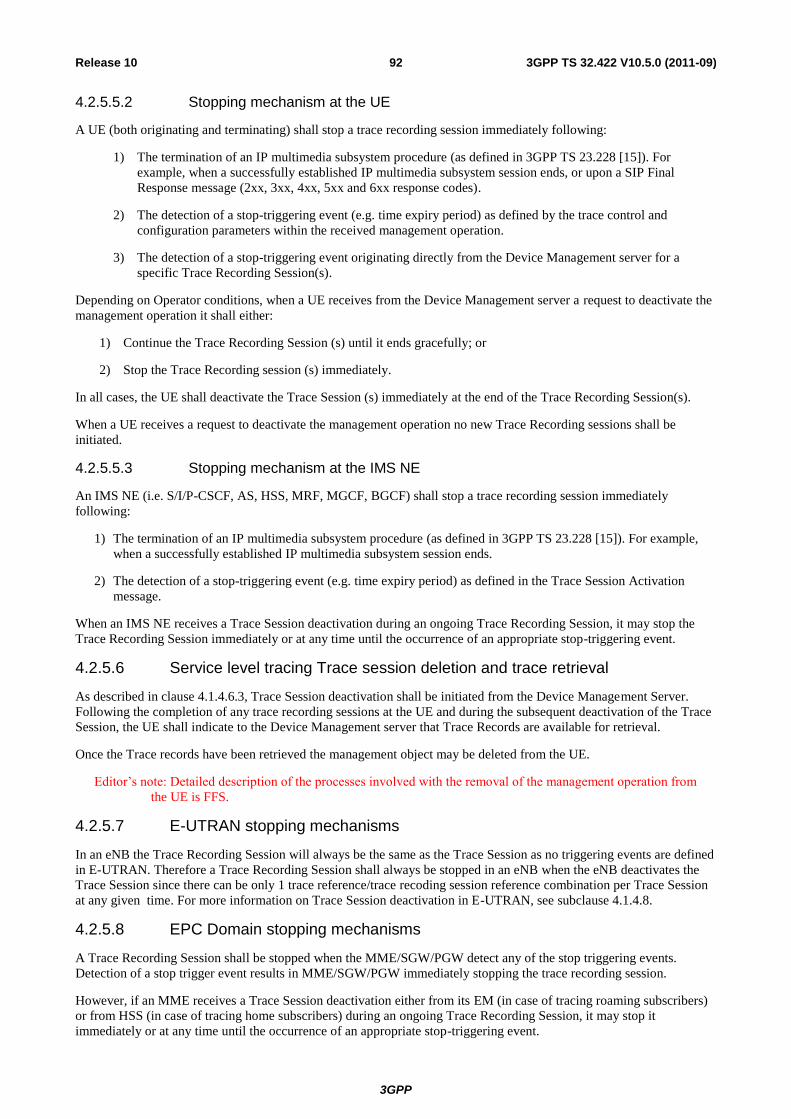
3GPP
3GPP TS 32.422 V10.5.0 (2011-09) 92 Release 10
4.2.5.5.2 Stopping mechanism at the UE
A UE (both originating and terminating) shall stop a trace recording session immediately following:
1) The termination of an IP multimedia subsystem procedure (as defined in 3GPP TS 23.228 [15]). For
example, when a successfully established IP multimedia subsystem session ends, or upon a SIP Final
Response message (2xx, 3xx, 4xx, 5xx and 6xx response codes).
2) The detection of a stop-triggering event (e.g. time expiry period) as defined by the trace control and
configuration parameters within the received management operation.
3) The detection of a stop-triggering event originating directly from the Device Management server for a
specific Trace Recording Session(s).
Depending on Operator conditions, when a UE receives from the Device Management server a request to deactivate the
management operation it shall either:
1) Continue the Trace Recording Session (s) until it ends gracefully; or
2) Stop the Trace Recording session (s) immediately.
In all cases, the UE shall deactivate the Trace Session (s) immediately at the end of the Trace Recording Session(s).
When a UE receives a request to deactivate the management operation no new Trace Recording sessions shall be
initiated.
4.2.5.5.3 Stopping mechanism at the IMS NE
An IMS NE (i.e. S/I/P-CSCF, AS, HSS, MRF, MGCF, BGCF) shall stop a trace recording session immediately
following:
1) The termination of an IP multimedia subsystem procedure (as defined in 3GPP TS 23.228 [15]). For example,
when a successfully established IP multimedia subsystem session ends.
2) The detection of a stop-triggering event (e.g. time expiry period) as defined in the Trace Session Activation
message.
When an IMS NE receives a Trace Session deactivation during an ongoing Trace Recording Session, it may stop the
Trace Recording Session immediately or at any time until the occurrence of an appropriate stop-triggering event.
4.2.5.6 Service level tracing Trace session deletion and trace retrieval
As described in clause 4.1.4.6.3, Trace Session deactivation shall be initiated from the Device Management Server.
Following the completion of any trace recording sessions at the UE and during the subsequent deactivation of the Trace
Session, the UE shall indicate to the Device Management server that Trace Records are available for retrieval.
Once the Trace records have been retrieved the management object may be deleted from the UE.
Editor’s note: Detailed description of the processes involved with the removal of the management operation from
the UE is FFS.
4.2.5.7 E-UTRAN stopping mechanisms
In an eNB the Trace Recording Session will always be the same as the Trace Session as no triggering events are defined
in E-UTRAN. Therefore a Trace Recording Session shall always be stopped in an eNB when the eNB deactivates the
Trace Session since there can be only 1 trace reference/trace recoding session reference combination per Trace Session
at any given time. For more information on Trace Session deactivation in E-UTRAN, see subclause 4.1.4.8.
4.2.5.8 EPC Domain stopping mechanisms
A Trace Recording Session shall be stopped when the MME/SGW/PGW detect any of the stop triggering events.
Detection of a stop trigger event results in MME/SGW/PGW immediately stopping the trace recording session.
However, if an MME receives a Trace Session deactivation either from its EM (in case of tracing roaming subscribers)
or from HSS (in case of tracing home subscribers) during an ongoing Trace Recording Session, it may stop it
immediately or at any time until the occurrence of an appropriate stop-triggering event.

3GPP
3GPP TS 32.422 V10.5.0 (2011-09) 93 Release 10
When a Trace Recording Session is stopped in an MME, the MME shall send a S1-Deactivate Trace message to the
eNB where tracing was required, as defined in the "List of NE types" configuration parameter, received in the Trace
Session activation message. The Trace Reference, used for the deactivation procedure, shall be the same as used in the
MME for the activation of the Trace Session. This only applies to the eNB as the PGW and SGW have their own
triggering criteria.
4.2.5.9 EPC stopping mechanisms for MDT
There is no stopping mechanism in the EPC for MDT trace recording sessions, as there are no starting mechanisms
either (see also 4.2.3.8).
4.2.5.10 E-UTRAN stopping mechanisms for MDT
In case of immediate MDT, the eNodeB shall stop an ongoing trace recording session for a given UE when a trace
session deactivation is received from the MME. The eNodeB shall deactivate the corresponding MDT measurements in
the UE.
If the configured area scope is not satifisfied in the target cell after a handover, the eNB may deactivate the Immediate
MDT configured to the UE like explained in sec. 4.2.6.
In case of logged MDT, there is no stopping mechanism in the eNodeB. The eNodeB does not need to maintain a
logged MDT trace recording session once it has been configured in the UE.
4.2.5.11 Stopping mechanisms at UE for MDT
In case of logged MDT, the UE shall stop an ongoing trace recording session when logging duration expires and it shall
indicate the availability of logged measurement results to the network next time it enters connected mode.
The UE shall discard an ongoing logged MDT trace recording session when it receives a new logged MDT trace
recording session configuration from the network.
4.2.6 Handling of MDT Trace sessions at handover for Immediate MDT
The eNB/RNC shall activate the Immediate MDT in the UE if the area based selection conditions are satisfied or not in
the target cell after a handover that is made over X2 or S1 (or over Iur or Iu in case of UMTS). If the area based
selection conditions are not satisfied in the handover target cell, the eNB/ RNC may deactivate the Immediate MDT in
the UE. In case of inter-PLMN handover, the eNB/RNC shall always deactivate the MDT in the UE in the source cell.
The trace sessions and trace recording sessions are not visible for the UE.
In case of signalling based trace activation (subscription based MDT), the eNB/RNC shall propagate the Trace Session
parameters together with the MDT specific parameters to the target cell regardless of whether the source or target cell is
part of the configured area scope in case of an Intra-PLMN handover over X2 or S1 (or Iur or Iu in case of UMTS).
In case of UTRAN the RNC shall propagate the Trace Session of the UE to the target cell in case of a handover over Iur
or Iu. Any trace recording session shall be maintained, stopped or started in the target cell according to the evaluation of
the selection criteria.
For signalling based MDT configuration (i.e. subscription based MDT), when a UE that has been configured with MDT
hands over to another eNB (i.e., in connected mode):
with an X2 handover: the MDT configuraiton shall be passed to the eNB in the X2 handover request for
continuity of MDT data collection . The new eNB shall stop the MDT collection if the new conditions are not
within the criteria for MDT data collection.
with an S1 handover and with no MME relocation: with S1 handover the MME shall ensure the MDT
configuration is sent to the new eNB.
with an S1 handover and with MME relocation: MDT configuration shall be passed on to the new MME on
MME relocation. The new MME, shall get the MDT configuration in the S1 HO message in case of intra-
PLMN HO and forward the MDT configuration to the new eNB.
The following MDT configuration shall be passed during handovers (Either intra-eNB, inter-eNB or inter-MME
HO):
Trace Session Reference

3GPP
3GPP TS 32.422 V10.5.0 (2011-09) 94 Release 10
Trace Recording Session Reference
Area scope
List of measurements
Report Amount
Reporting Trigger
Event Threshold
Report Interval
IP address of TCE
Job type
When these MDT configuration parameters are passed to a new MME, they shall be used with the UE context
on the new MME. During inter-MME TAU, the MME shall propagate the MDT configuration parameters to the
target MME within an S10- Context Response as part of inter-MME TAU procedures.
During inter-MME handover, the MME shall propagate the MDT configuration parameters to the target MME
within an S10- Forward Relocation Request message as part of inter-MME handover procedures.
4.2.7 Handling of MDT Trace sessions at handover for Logged MDT
In logged MDT mode, no propagation of the MDT configuration is performed.
4.2.8 User consent handling in MDT
4.2.8.1 Signalling based MDT
In case of signalling based MDT getting user consent before activating the MDT functionality is required because of
privacy and legal obligations. It is the Operator responsibility to collect user consent before initiating an MDT for a
specific IMSI or IMEI number.
Collecting the user consent shall be done via customer care process. The user consent information availability should be
considered as part of the subscription data and as such this shall be provisioned to the HSS database.
The following figure summarizes the functionality.

3GPP
3GPP TS 32.422 V10.5.0 (2011-09) 95 Release 10
OAM HSS MME/SGSN/MSC-S eNB/RNC
Storing User
consent of the
specific user
Is user consent
availale
user consent provisioning
IMSI based MDT
activation
NoReject MDT activation
User consent is
available
MDT activation
MDT activation
When the IMSI based MDT is activated it is targeted the HSS. Once the user consent availability information is stored
in the HSS database, the HSS can check the user consent availability before starting a Trace Session for the given
subscriber. If there is no user consent given by the specific user, the HSS should not start a Trace Session for the given
subscriber.
As the user consent availability information is stored as part of the subscription data it should also be transferred to the
MME/SGSN/MSC-S during update location procedure. This is required if the subscription based MDT is started from
MME/SGSN/MSC-S. In that case similar checking is required as in the HSS case.
It should also be possible to handle user consent revocation. The process of user consent revocation shall be done also
via customer care process and the user consent availability information should be updated in the HSS DB when a user
consent revocation happens.
If the user consent revocation happens during an ongoing Trace Session with MDT, it is not required to stop and
deactivate the Trace Recording Session, Trace Session respectively immediately i.e. to stop an ongoing Trace
Recording Session in case of Immediate MDT. A notification to the management system should be sent and the
management system should deactivate the Trace Session .
4.2.8.2 Area based MDT
In case of area based MDT getting user consent is required before activating the MDT functionality because of privacy
and legal obligations. The same user consent information can be used for area based MDT and for signalling based
MDT (i.e. there is no need to differentiate the user consent per MDT type).
Collecting the user consent shall be done via customer care process. The user consent information availability shall be
considered as part of the subscription data and as such this shall be provisioned to the HSS database.
The following figure shows an example scenario summarizing the functionality.

3GPP
3GPP TS 32.422 V10.5.0 (2011-09) 96 Release 10
EM HSS
UE context setup
user consent provisioning
Storing user consent
information of the
specific subscriber
Is UE
attached to
the
network?
NoDo
nothing
yes Insert Subscriber Data
Incl. user consent
Storing user consent
information of the
specific subscriber
Transferring user consent
Area Based MDT activation
UE selection based on
received criteria for
only consented users
MDT activation
MME/SGSN/MSC-S RNC/eNB UE1
Storing user
consent within UE
context
Figure 4.2.8.2.1 Example for delivering user consent information in area based MDT
When UE attaches to the network, the HSS shall forward the user consent information, stored in the HSS database, to
the corresponding MME/SGSN/MSC-S. When the MME/SGSN/MSC-S receive the user consent information it shall
store it in its subscriber database.
The MME/SGSN/MSC-S shall also check the roaming status of the user. If the user is within his home operator’s
PLMNs in the home country and the user has given his consent, the MME/ SGSN/MSC-S shall send the user consent
information to the eNB/RNC during the UE context setup procedure. Otherwise the MME/ SGSN/MSC-S shall not send
the user consent information to the eNB/RNC.
If the result of the roaming status check indicates a home subscriber, MME/SGSN/MSC-S shall forward the already
stored user consent information to the corresponding eNodeB/RNC.
3GPP
3GPP TS 32.422 V10.5.0 (2011-09) 97 Release 10
When the area based MDT activation is sent to eNodeB/RNC, eNodeB/RNC shall check the user consent information
before making the UE selection. In case the user consent for UE is not available or indicates that no user consent is
available, the eNodeB/RNC shall not select the UE to join the MDT campaign.
The eNB/RNC shall forward the received user consent information during X2/Iur based handovers to the target node.
The user consent information is stored in the eNB/RNC as part of the UE context. If the user consent information is
updated while a UE context is already set up in the eNB, the changed user consent should be taken into account in the
next call/session setup.
4.2.9 Anonymization of MDT data for area based MDT
In case of E-UTRAN the anonymization of MDT data depends on the configuration parameter received at the MDT
configuration. There are two levels of anonymization:
Using TAC part of IMEI
Not sending any identity to the TCE.
If the anonymization indicates that no identity should be sent to the TCE, the eNB should not send the CELL TRAFFIC
TRACE message to the MME.
If the anonymization indicates that the TAC is required, eNB should send the CELL TRAFFIC TRACE message to the
MME. MME shall look up of the TAC of IMEI and send to the TCE.
In case of UTRAN The RNC shall never send IMSI to the TCE.

3GPP
3GPP TS 32.422 V10.5.0 (2011-09) 98 Release 10
5 Trace/UE measurement control and configuration parameters
5.1 Triggering events (M)
This mandatory parameter defines when to start a Trace Recording Session and which message shall be recorded first, when to stop a Trace Recording Session and which message
shall be recorded last respectively. The messages in the start triggering event tables indicate the transaction to be recorded first and the starting time of the Trace Recording Session
within a Trace Session for the traced MS/subscriber in the given NE.
The messages in the stop triggering event tables indicate the transaction to be recorded last and the stopping time of the Trace Recording Session.
MSC Server Start triggering events Stop triggering events
Mobile Originated Call Receipt of the CM SERVICE-REQUEST message with service type set to originating call establishment
Reception of CC-RELEASE COMPLETE or CM-SERVICE ABORT message
Mobile Terminated Call Sending of PAGING REQUEST message Reception of CC-RELEASE COMPLETE or CM-SERVICE ABORT message
Mobile Originated SMS Receipt of the CM SERVICE-REQUEST message with service type set to Short Message service
Transmission of RP-ACK/RP-NACK message
Mobile Terminated SMS Sending of PAGING REQUEST message Reception of RP-ACK/RP-NACK message
IMSI Attach Receipt of the MM-LOCATION UPDATING REQUEST message Sending of MM-LOCATION-UPDATING ACCEPT or MM-LOCATION-UPDATING-REJECT message
Location Update Receipt of the MM-LOCATION UPDATING REQUEST message Sending of MM-LOCATION-UPDATING ACCEPT or MM-LOCATION-UPDATING-REJECT message
IMSI Detach Receipt of the MM-IMSI DETACH INDICATION message Reception of MM-IMSI DETACH INDICATION message
Handover Receipt of the BSSMAP-HANDOVER-REQUIRED message in case of GSM or RANAP-RELOCATION-REQUIRED message in case of UMTS
Reception of BSSMAP-CLEAR COMPLETE message in case of GSM or RANAP-IU RELEASE COMPLETE message in case of UMTS or BSSMAP-HANDOVER FAILURE in case of GSM or RANAP-RELOCATION FAILURE in case of UMTS.
Supplementary Service TBD TBD
MGW Start triggering events Stop triggering events
Context Reception of H.248-ADD command, or reception of H.248 MODIFY command Sending of H.248- SUBTRACT reply

3GPP
3GPP TS 32.422 V10.5.0 (2011-09) 99 Release 10
SGSN Start triggering events Stop triggering events
PDP Context Reception of SM-ACTIVATE PDP CONTEXT REQUEST or sending SM-REQUEST PDP CONTEXT ACTIVATION or reception of SM- MODIFY PDP CONTEXT REQUEST
Reception or sending of SM- DEACTIVATE PDP CONTEXT REQUEST or sending SM-ACTIVATE PDP CONTEXT REJECT
Mobile Originated SMS Receipt of RP-DATA message Transmission of RP-ACK/RP-NACK message
Mobile Terminated SMS Transmission of RP-DATA message Reception of RP-ACK/RP-NACK message
GPRS Attach Reception of MM-ATTACH-REQUEST Sending MM-ATTACH-ACCEPT or MM-ATTACH-REJECT
Routing Area Update Reception of MM-ROUTING AREA UPDATE REQUEST Sending MM-ROUTING AREA UPDATE ACCEPT or MM-ROUTING AREA UPDATE REJECT
GPRS Detach Reception MM-DETACH REQUEST Reception of MM-DETACH ACCEPT
MBMS Context Sending SM-Request MBMS Context Activation or reception of SM-Update MBMS Context Request
Sending of SM-Deactivate MBMS Context Request or sending of SM-Activate MBMS Context Reject
GGSN Start triggering events Stop triggering events
PDP Context Reception of GTP Create PDP context request or reception of GTP Update PDP context request Sending of GTP Delete PDP context response
MBMS Context Reception of GTP Create MBMS Context Request or reception of GTP Update MBMS Context Request Sending of GTP Delete MBMS Context Response
IMS Network Element Start triggering events Stop triggering events
SIP session or standalone transaction
Reception of an initial SIP request that matches the start trigger event configured by the Management System via the Trace IRP TS 32.442 [24]
Sending of a SIP final response to a SIP BYE or other request (originating or terminating), timer expiry or other event that matches the stop trigger event configured by the Management System via the Trace IRP TS 32.442 [24].
BM-SC Start triggering events Stop triggering events
MBMS Multicast service activation
Reception of MBMS Authorization Request
Reception of Deactivation Indication for user deactivation or sending of Session Stop Request for service deactivation
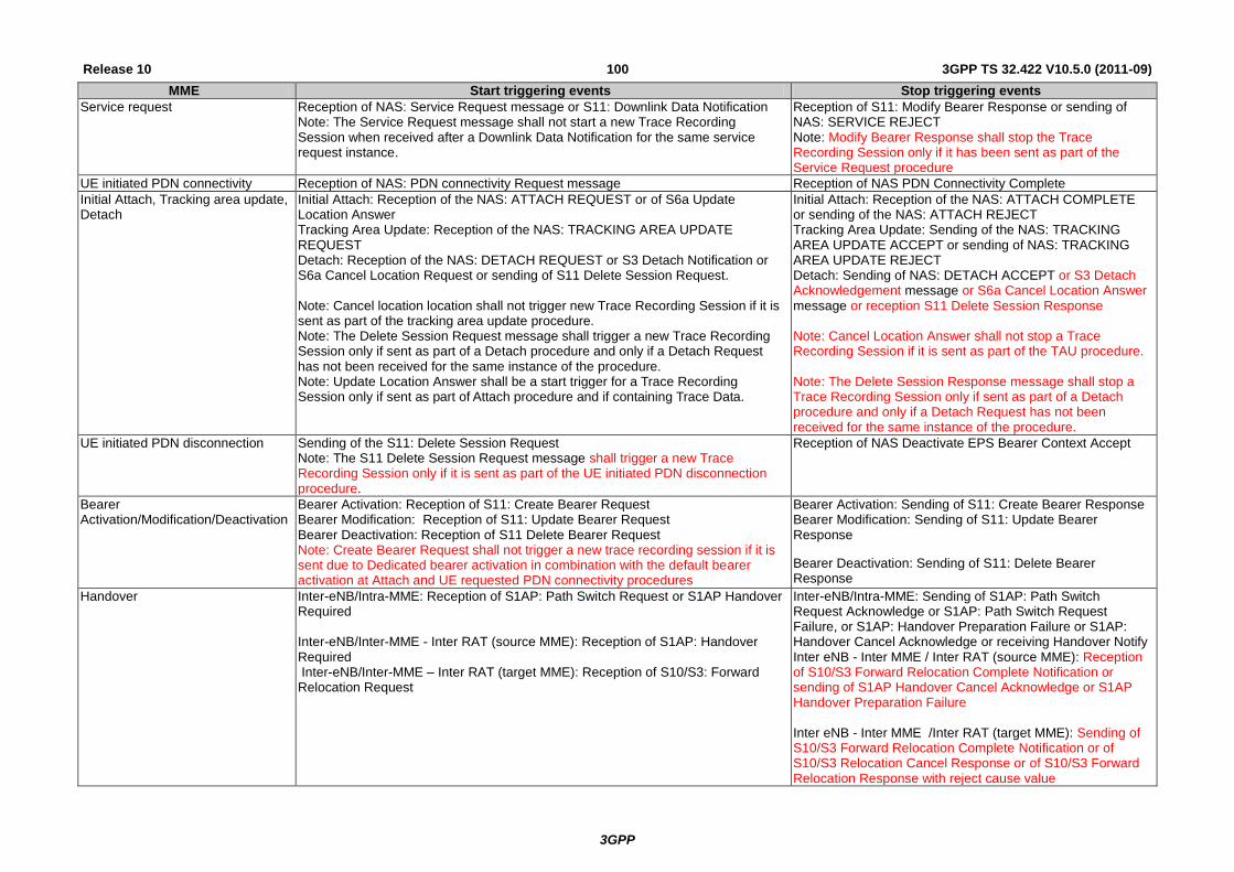
3GPP
3GPP TS 32.422 V10.5.0 (2011-09) 100 Release 10
MME Start triggering events Stop triggering events
Service request Reception of NAS: Service Request message or S11: Downlink Data Notification Note: The Service Request message shall not start a new Trace Recording Session when received after a Downlink Data Notification for the same service request instance.
Reception of S11: Modify Bearer Response or sending of NAS: SERVICE REJECT Note: Modify Bearer Response shall stop the Trace Recording Session only if it has been sent as part of the Service Request procedure
UE initiated PDN connectivity Reception of NAS: PDN connectivity Request message Reception of NAS PDN Connectivity Complete
Initial Attach, Tracking area update, Detach
Initial Attach: Reception of the NAS: ATTACH REQUEST or of S6a Update Location Answer Tracking Area Update: Reception of the NAS: TRACKING AREA UPDATE REQUEST Detach: Reception of the NAS: DETACH REQUEST or S3 Detach Notification or S6a Cancel Location Request or sending of S11 Delete Session Request. Note: Cancel location location shall not trigger new Trace Recording Session if it is sent as part of the tracking area update procedure. Note: The Delete Session Request message shall trigger a new Trace Recording Session only if sent as part of a Detach procedure and only if a Detach Request has not been received for the same instance of the procedure. Note: Update Location Answer shall be a start trigger for a Trace Recording Session only if sent as part of Attach procedure and if containing Trace Data.
Initial Attach: Reception of the NAS: ATTACH COMPLETE or sending of the NAS: ATTACH REJECT Tracking Area Update: Sending of the NAS: TRACKING AREA UPDATE ACCEPT or sending of NAS: TRACKING AREA UPDATE REJECT Detach: Sending of NAS: DETACH ACCEPT or S3 Detach Acknowledgement message or S6a Cancel Location Answer message or reception S11 Delete Session Response Note: Cancel Location Answer shall not stop a Trace Recording Session if it is sent as part of the TAU procedure. Note: The Delete Session Response message shall stop a Trace Recording Session only if sent as part of a Detach procedure and only if a Detach Request has not been received for the same instance of the procedure.
UE initiated PDN disconnection Sending of the S11: Delete Session Request Note: The S11 Delete Session Request message shall trigger a new Trace Recording Session only if it is sent as part of the UE initiated PDN disconnection procedure.
Reception of NAS Deactivate EPS Bearer Context Accept
Bearer Activation/Modification/Deactivation
Bearer Activation: Reception of S11: Create Bearer Request Bearer Modification: Reception of S11: Update Bearer Request Bearer Deactivation: Reception of S11 Delete Bearer Request Note: Create Bearer Request shall not trigger a new trace recording session if it is sent due to Dedicated bearer activation in combination with the default bearer activation at Attach and UE requested PDN connectivity procedures
Bearer Activation: Sending of S11: Create Bearer Response Bearer Modification: Sending of S11: Update Bearer Response
Bearer Deactivation: Sending of S11: Delete Bearer Response
Handover Inter-eNB/Intra-MME: Reception of S1AP: Path Switch Request or S1AP Handover Required Inter-eNB/Inter-MME - Inter RAT (source MME): Reception of S1AP: Handover Required Inter-eNB/Inter-MME – Inter RAT (target MME): Reception of S10/S3: Forward Relocation Request
Inter-eNB/Intra-MME: Sending of S1AP: Path Switch Request Acknowledge or S1AP: Path Switch Request Failure, or S1AP: Handover Preparation Failure or S1AP: Handover Cancel Acknowledge or receiving Handover Notify Inter eNB - Inter MME / Inter RAT (source MME): Reception of S10/S3 Forward Relocation Complete Notification or sending of S1AP Handover Cancel Acknowledge or S1AP Handover Preparation Failure Inter eNB - Inter MME /Inter RAT (target MME): Sending of S10/S3 Forward Relocation Complete Notification or of S10/S3 Relocation Cancel Response or of S10/S3 Forward Relocation Response with reject cause value

3GPP
3GPP TS 32.422 V10.5.0 (2011-09) 101 Release 10
SGW Start triggering events Stop triggering events
PDN connection creation Reception of the S11: Create Session Request Sending of the S11: Create Session Response
PDN connection termination Reception of the S11: Delete Session Request Sending of the S11: Delete Session Response
Bearer Activation/Modification/Deactivation
Bearer Activation: Reception of the S5: Create Bearer Request or S11: Bearer Resource Command Bearer Modification: Reception of the S11: Modify Bearer Request or S5: Update Bearer Request Bearer Deletion: Reception of the S11: Deactivate Bearer Command or S5: Delete Bearer Request
Bearer Activation: Sending of the S5: Create Bearer Response Bearer Modification: Sending of the S11: Modify Bearer Response or S5: Update Bearer Response Bearer Deletion: Sending of S5: Delete Bearer Response
PGW Start triggering events Stop triggering events
PDN connection creation Reception of S5: Create Session Request (GTP) or Proxy Binding Update (PMIP) Reception of S2b: Create Session Request (GTP)
Sending of S5: Create Session Response (GTP) or Proxy Binding Update Ack (PMIP) Sending of S2b: Create Session Response (GTP)
PDN connection termination Reception of the S5: Delete Session Request or Proxy Binding Update Reception of the S2b: Delete Session Request
Sending of the S5: Delete Session Response (GTP) or Proxy Binding Update ACK (PMIP) Sending of the S2b: Delete Session Response (GTP)
Bearer Activation/Modification/Deactivation Note: this is applicable only to GTP based S5 interface.
Bearer Activation: Sending of the S5/S2b: Create Bearer Request Bearer Modification: Reception of the S5: Modify Bearer Request or sending of the S5/S2b: Update Bearer Request Bearer Deletion: Reception of the S5: Delete Bearer Command or sending of S5/S2b: Delete Bearer Request
Bearer Activation: Reception of the S5/S2b: Create Bearer Response Bearer Modification: Sending of the S5: Modify Bearer Response or reception of the S5/S2b: Update Bearer Response Bearer Deletion: Reception of the S5/S2b: Delete Bearer Response

3GPP
3GPP TS 32.422 V10.5.0 (2011-09) 102 Release 10
Bit 8 Bit 7 Bit 6 Bit 5 Bit 4 Bit 3 Bit 2 Bit 1
MSC Server
MGW
SGSN
GGSN
BM-SC
MME
PGW SGW
MSC Server
Bit 8 Bit 7 Bit 6 Bit 5 Bit 4 Bit 3 Bit 2 Bit 1
spare spare SS Handovers LU, IMSI attach, IMSI detach MO and MT SMS MO and MT calls
spare
MGW
Bit 8 Bit 7 Bit 6 Bit 5 Bit 4 Bit 3 Bit 2 Bit 1
spare spare Context
SGSN
Bit 8 Bit 7 Bit 6 Bit 5 Bit 4 Bit 3 Bit 2 Bit 1
spare MBMS Context RAU, GPRS attach, GPRS detach MO and MT SMS PDP context
Reserved
GGSN
Bit 8 Bit 7 Bit 6 Bit 5 Bit 4 Bit 3 Bit 2 Bit 1
spare MBMS Context PDP Context
MME
Bit 8 Bit 7 Bit 6 Bit 5 Bit 4 Bit 3 Bit 2 Bit 1
spare Spare Handover Bearer Activation
Modification Deletion
UE initiated PDN
disconnection
Initial Attach,
Tracking area
update, Detach
Service requests
UE initiated PDN connectivity request
PGW SGW
Bit 8 Bit 7 Bit 6 Bit 5 Bit 4 Bit 3 Bit 2 Bit 1
spare Bearer Activation
Modification Deletion
PDN connection termination
PDN connection
creation
Spare Bearer Activation
Modification Deletion
PDN connection termination
PDN Connection
creation
If a bit is set to 1 the given event shall be traced, i.e. a Trace Recording Session shall be started for that event.
If a bit is set to 0 the given event should not be traced, i.e. Trace Recording Session should not be started.
5.2 Service Level Tracing Start Triggering event (M)
The Service Level Tracing Start Triggering Event is a mandatory parameter that controls and coordinates the start of a
Trace Recording Session at an IMS NE and UE.
The Service Level Tracing Start Trigger Event shall include:

3GPP
3GPP TS 32.422 V10.5.0 (2011-09) 103 Release 10
Public User Identity (M);
Service identification (M);
Trace reference (M);
Service level tracing counter (M);
The service level tracing counter is incremented on a hop-by-hop basis to indicate the sequence of trace records
recorded across all IMS NEs.
5.3 Trace Depth (M)
This mandatory parameter defines how detailed information should be recorded in the Network Element. The Trace
Depth is a paremeter for Trace Session level, i.e., the Trace Depth is the same for all of the NEs to be traced in the same
Trace Session.
The following table describes the values of the Trace Depth parameter.
Trace Depth Meaning
Minimum Recording of some IEs in the signalling messages plus any vendor specific extensions to this definition, in decoded format.
Medium Recording of some IEs in the signalling messages together with the radio measurement IEs plus any vendor specific extensions to this definition, in decoded format.
Maximum Recording entire signalling messages plus any vendor specific extensions to this definition, in encoded format.
MinimumWithoutVendorSpecificExtension Recording of some IEs in the signalling messages in decoded format.
MediumWithoutVendorSpecificExtension Recording of some IEs in the signalling messages together with the radio measurement IEs in decoded format.
MaximumWithoutVendorSpecifcExtension Recording entire signalling messages in encoded format.
At least one of Minimum, Medium or Maximum trace Depth shall be supported depending on the NE type (see trace
record description in TS 32.423 [3] for details).
Trace depth shall be an enumerated parameter with the following possible values:
0 –Minimum,
1 – Medium
2 – Maximum
3 – MinimumWithoutVendorSpecificExtension
4 – MediumWithoutVendorSpecificExtension
5 - MaximumWithoutVendorSpecificExtension
5.4 List of NE types (M)
This conditional mandatory parameter defines the Network Element types where Trace Session activation is needed.
The condition of this parameter is that signalling based activation mechanism is used except in IMS. This parameter
determines whether the Trace Session Activation shall be propagated further to other Network Elements. In the
management based activation mechanism, and in the signalling based activation mechanism for IMS, this parameter is
not needed.
The following list contains the Network Element types:
MSC Server
MGW
RNC
SGSN
GGSN
BM-SC
MME
SGW
PDN GW

3GPP
3GPP TS 32.422 V10.5.0 (2011-09) 104 Release 10
eNB
Bit 8 Bit 7 Bit 6 Bit 5 Bit 4 Bit 3 Bit 2 Bit 1
SGW MME BM-SC RNC GGSN SGSN MGW MSC-S
spare eNB PDN GW
If a bit is set to 1, Trace Session to that Network Element shall be activated.
If a bit is set to 0, Trace Session is not needed in that Network Element.

3GPP
3GPP TS 32.422 V10.5.0 (2011-09) 105 Release 10
5.5 List of interfaces (O)
This is an optional parameter, which defines the interfaces to be recorded in the Network Element.
The following list contains the list of interfaces in each Network Element:
MSC Server: A, Iu-CS, Mc and MAP (G, B, E, F, D, C) interfaces, CAP.
MGW: Mc, Nb-UP, Iu-UP.
RNC: Iu-CS, Iu-PS, Iur, Iub and Uu interfaces.
SGSN: Gb, Iu-PS, Gn, MAP (Gr, Gd, Gf), CAP (Ge), Gs, S6d, S4, S3, S13' interfaces.
GGSN: Gn, Gi and Gmb interfaces.
S-CSCF: Mw, Mg, Mr and Mi interfaces.
P-CSCF: Gm and Mw interfaces.
I-CSCF: Cx, Dx, Mg, Mw.
MRFC: Mp, Mr.
MGCF: Mg, Mj, Mn.
IBCF: Ix, Mx.
E-CSCF: Mw, Ml, Mm, Mi/Mg.
BGCF: Mi, Mj, Mk.
AS: Dh, Sh, ISC, Ut.
HSS: MAP (C, D, Gc, Gr), Cx, S6d interfaces, S6a, Sh and location and subscription information.
EIR: MAP (F), S13, S13’, MAP (Gf)
BM-SC: Gmb interface.
MME: S1-MME, S3, S6a, S10, S11, S13
SGW: S4, S5, S8, S11, Gxc
PDN GW: S2a, S2b, S2c, S5, S6b, Gx, S8, SGi
eNB: S1-MME, X2, Uu
NOTE: For IMS Network Elements other than P-CSCF and S-CSCF the interfaces included in the Trace Job for a
particular type of IMS session are configured in the Management System via the Trace IRP (3GPP TS
32.442 [24]).

3GPP
3GPP TS 32.422 V10.5.0 (2011-09) 106 Release 10
Bit 8 Bit 7 Bit 6 Bit 5 Bit 4 Bit 3 Bit 2 Bit 1
MSC Server
MGW
SGSN
GGSN
RNC
BM-SC
MME
SGW
PDN GW
eNB
HSS
EIR
MSC Server
Bit 8 Bit 7 Bit 6 Bit 5 Bit 4 Bit 3 Bit 2 Bit 1
CAP MAP-F MAP-E MAP-B MAP-G Mc Iu A
spare MAP-C MAP-D
SGSN
Bit 8 Bit 7 Bit 6 Bit 5 Bit 4 Bit 3 Bit 2 Bit 1
Ge Gs MAP-Gf MAP-Gd MAP-Gr Gn Iu Gb
spare S13' S3 S4 S6d
MGW
Bit 8 Bit 7 Bit 6 Bit 5 Bit 4 Bit 3 Bit 2 Bit 1
Spare Iu-UP Nb-UP Mc
GGSN
Bit 8 Bit 7 Bit 6 Bit 5 Bit 4 Bit 3 Bit 2 Bit 1
spare Gmb Gi Gn
RNC
Bit 8 Bit 7 Bit 6 Bit 5 Bit 4 Bit 3 Bit 2 Bit 1
Spare Uu Iub Iur Iu
BM-SC
Bit 8 Bit 7 Bit 6 Bit 5 Bit 4 Bit 3 Bit 2 Bit 1
spare Gmb
MME
Bit 8 Bit 7 Bit 6 Bit 5 Bit 4 Bit 3 Bit 2 Bit 1
Spare S13 S11 S10 S6a S3 S1-MME
SGW
Bit 8 Bit 7 Bit 6 Bit 5 Bit 4 Bit 3 Bit 2 Bit 1
Spare Gxc S11 S8b S5 S4
PDN GW
Bit 8 Bit 7 Bit 6 Bit 5 Bit 4 Bit 3 Bit 2 Bit 1
SGi S8b Gx S6b S5 S2c S2b S2a

3GPP
3GPP TS 32.422 V10.5.0 (2011-09) 107 Release 10
eNB
Bit 8 Bit 7 Bit 6 Bit 5 Bit 4 Bit 3 Bit 2 Bit 1
Spare Uu X2 S1-MME
HSS
Bit 8 Bit 7 Bit 6 Bit 5 Bit 4 Bit 3 Bit 2 Bit 1
Sh S6a S6d Cx MAP-Gr MAP-Gc MAP-D MAP-C
EIR
Bit 8 Bit 7 Bit 6 Bit 5 Bit 4 Bit 3 Bit 2 Bit 1
Spare MAP-Gf S13’ S13 MAP-F
If a bit is set to 1, the interface should be traced in the given Network Element.
If a bit is set to 0, that interface should not be traced in the given Network Element.
5.6 Trace Reference (M)
The Trace Reference parameter shall be globally unique, therefore the Trace Reference shall compose as follows:
MCC+MNC+Trace ID, where the MCC and MNC are coming with the Trace activation request from the EM/NM to
identify one PLMN containing the EM/NM, and Trace ID is a 3 byte Octet String.
NOTE: Trace ID referred here is the same as Trace reference in previous releases
NOTE: The MCC+MNC being part of the Trace Reference from Rel-8 onwards (e.g. ignored by Rel-6 / Rel-7
UTRAN Network Elements), the uniqueness of the Trace Reference may not be guaranteed with Rel-6 /
Rel-7 Network Element(s) involved in the Trace.
5.7 Trace Recording Session Reference (M)
This parameter shall be a 2 byte Octet String.
5.8 Void
5.9 IP Address of Trace Collection Entity (M)
This is a mandatory parameter which defines the IP address to which the Trace records shall be transferred. IPv4 and/or
IPv6 address(es) may be signalled.
5.10 MDT specific configuration parameters (CM)
5.10.1 Job type
The Job type parameter defines the MDT mode and whether a combined MDT and trace job is requested. The Job type
parameter is an enumerated type with the following values:
- Immediate MDT only (0);
- Logged MDT only (1);
- Trace only (2);
- Immediate MDT and Trace (3).
The parameter is mandatory.

3GPP
3GPP TS 32.422 V10.5.0 (2011-09) 108 Release 10
5.10.2 Area Scope
The Area Scope optional parameter defines the area in terms or Cells or Tracking Area/Routing Area/Location Area
where the MDT data collection shall take place. The area scope specified in a MDT session shall support the same
PLMN. If the parameter is not present the MDT data collection shall be done in the whole PLMN.
The Area Scope parameter in UMTS is either
list of Cells, identified by CGI. Maximum 32 CGI can be defined.
List of Routing Area, identified by RAI. Maximum of 8 RAIs can be defined.
List of Location Area, identified by LAI. Maximum of 8 LAIs can de defined.
The Area Scope parameter in LTE is either
list of Cells, identified by E-UTRAN-CGI. Maximum 32 CGI can be defined.
List of Tracking Area, identified by TAC. Maximum of 8 TAC can be defined.
5.10.3 List of measurements
This parameter is mandatory if the Job type is configured for Immediate MDT. This parameter defines the
measurements that shall be collected. The parameter is 4 octet long bitmap with the following values in UMTS:
M1: CPICH RSCP and CPICH Ec/No measurement by UE with Periodic or event 1F as reporting triggers.
M2: For 1.28 Mcps TDD, P-CCPCH RSCP and Timeslot ISCP measurement by UE with event 1I as
reporting triggers.
M3: SIR and SIR error (FDD) by NodeB
Both M1 and M2
M1 and M3
M2 and M3
M1 and M2 and M3
The parameter can have the following values in LTE:
M1: RSRP and RSRQ measurement by UE with Periodic, event A2 as reporting triggers
M2: Power Headroom (PH) measurement by UE
NOTE: Available from MAC layer
M1 and M2
LTE
Bit 8 Bit 7 Bit 6 Bit 5 Bit 4 Bit 3 Bit 2 Bit 1
spare M2 M1
spare
UMTS
Bit 8 Bit 7 Bit 6 Bit 5 Bit 4 Bit 3 Bit 2 Bit 1
spare M3 M2 M1
spare
5.10.4 Reporting Trigger
This parameter is mandatory if the list of measurements parameter is configured for M1 and the jobtype is configured
for Immediate MDT.
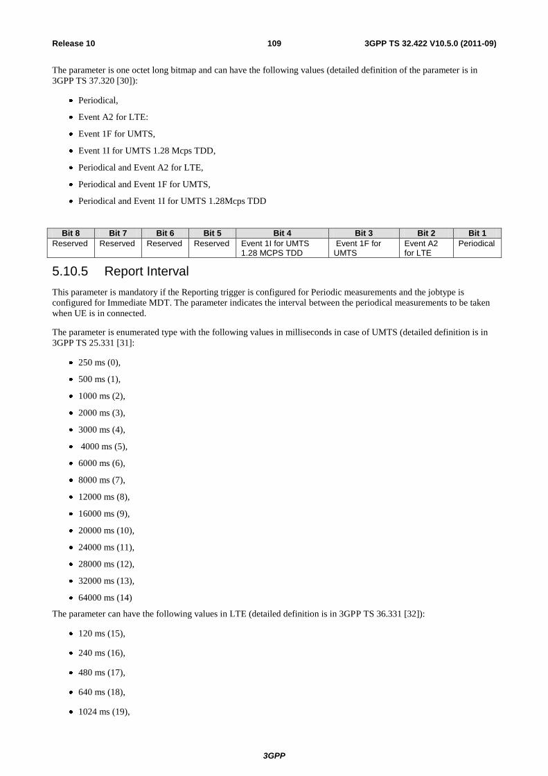
3GPP
3GPP TS 32.422 V10.5.0 (2011-09) 109 Release 10
The parameter is one octet long bitmap and can have the following values (detailed definition of the parameter is in
3GPP TS 37.320 [30]):
Periodical,
Event A2 for LTE:
Event 1F for UMTS,
Event 1I for UMTS 1.28 Mcps TDD,
Periodical and Event A2 for LTE,
Periodical and Event 1F for UMTS,
Periodical and Event 1I for UMTS 1.28Mcps TDD
Bit 8 Bit 7 Bit 6 Bit 5 Bit 4 Bit 3 Bit 2 Bit 1
Reserved Reserved Reserved Reserved Event 1I for UMTS 1.28 MCPS TDD
Event 1F for UMTS
Event A2 for LTE
Periodical
5.10.5 Report Interval
This parameter is mandatory if the Reporting trigger is configured for Periodic measurements and the jobtype is
configured for Immediate MDT. The parameter indicates the interval between the periodical measurements to be taken
when UE is in connected.
The parameter is enumerated type with the following values in milliseconds in case of UMTS (detailed definition is in
3GPP TS 25.331 [31]:
250 ms (0),
500 ms (1),
1000 ms (2),
2000 ms (3),
3000 ms (4),
4000 ms (5),
6000 ms (6),
8000 ms (7),
12000 ms (8),
16000 ms (9),
20000 ms (10),
24000 ms (11),
28000 ms (12),
32000 ms (13),
64000 ms (14)
The parameter can have the following values in LTE (detailed definition is in 3GPP TS 36.331 [32]):
120 ms (15),
240 ms (16),
480 ms (17),
640 ms (18),
1024 ms (19),

3GPP
3GPP TS 32.422 V10.5.0 (2011-09) 110 Release 10
2048 ms (20),
5120 ms (21),
10240ms (22),
1 min=60000 ms (23),
6 min=360000 ms (24),
12 min=720000 ms (25),
30 min=1800000 ms (26),
60 min=3600000 ms (27)
5.10.6 Report Amount
The parameter is mandatory if the reporting trigger is configured for periodical measurement and the jobtype is
configured for Immediate MDT. The parameter defines the number of measurement reports that shall be taken for
periodical reporting while UE is in connected. Detailed definition of the paremeter is in 3GPP TS 36.331 and 3GPP TS
25.331[31].
The parameter is an enumerated type with the following values in UMTS and in LTE:
1 (0),
2 (1),
4 (2),
8 (3),
16 (4),
32 (5),
64 (6),
infinity (7)
5.10.7 Event Threshold for RSRP
The parameter is mandatory if the report trigger parameter is configured for A2 event reporting and the job type
parameter is configured for Immediate MDT.
Detailed definition of the parameter is in 3GPP TS 36.331 [32].
The parameter is an Integer number between 0-97.
5.10.7a Event Threshold for RSRQ
The parameter is mandatory if the report trigger parameter is configured for A2 event reporting and the job type
parameter is configured for Immediate MDT.
Detailed definition of the parameter is in 3GPP TS 36.331 [32].
The parameter is an Integer number between 0-34.
5.10.8 Logging Interval
The parameter is mandatory if the job type is configured for Logged MDT. The parameter defines the periodicity for
logging MDT measurement results for periodic downlink pilot strength measurement when UE is in Idle.
Detailed definition of the parameter is in 3GPP TS 37.320 [30].

3GPP
3GPP TS 32.422 V10.5.0 (2011-09) 111 Release 10
The parameter is an enumerated type with the following values in UMTS and LTE as per defined in 3GPP TS 25.331
[31] and 36.331 [32]:
1.28 (0),
2.56 (1),
5.12 (2),
10.24 (3),
20.48 (4),
30.72 (5),
40.96 (6),
61.44 (7)
5.10.9 Logging Duration
The parameter is mandatory if the the job type parameter is configured for Logged MDT. The parameter determines the
validity of MDT logged configuration for IDLE. The timer starts at time of receiving configuration by the UE, and
continues independent of UE state transitions and RAT or RPLMN changes.
Detailed definition of the parameter is in 3GPP TS 37.320 [30], 3GPP TS 25.331 [31] and 3GPP TS 36.331 [32]:
The parameter is an enumerated type with the following values in UMTS and LTE:
600sec (0),
1200sec (1),
2400sec (2),
3600sec (3),
5400sec (4),
7200sec (5)
5.10.10 Void
5.10.11 Trace Collection Entity Id
This is a mandatory parameter for Logged MDT which defines the TCE Id which is sent to the UE. The UE returns it to
the network together with the logged data. The network has a configured mapping of the IP address of the TCE (to
which the Trace records shall be transferred) and the TCE Id. The mapping needs to be unique within the PLMN. The
size of the parameter is one byte.

3GPP
3GPP TS 32.422 V10.5.0 (2011-09) 112 Release 10
6 MDT Reporting
MDT reporting in case of Immediate MDT:
Figure 6-1 illustrates an example of the procedure for Immediate MDT reporting.
Figure 6-1:
In case of Immediate MDT, the MDT related measurements are sent in RRC as part of the existing RRC measurements.
Whenever the eNB/RNC receives the MDT measurements it shall save it to a Trace Record. The Trace Records are sent
to the TCE vie EM (where EM can reside in the eNB/RNC).
The time and the criteria when the Trace Records are sent to the TCE is vendor specific however if the Trace Session is
deactivated, the Trace Records shall be sent to the TCE latest by 2 hours ( the exact time is FFS) after the Trace Session
deactivation.
UE RNC / eNB EM TCE
MDT configuration
MDT reporting in RRC
MDT reporting in RRC
Saving MDT measurements
MDT reporting in RRC
Saving MDT measurements
Saving MDT measurements
Sending Trace Record
Sending Trace Record

3GPP
3GPP TS 32.422 V10.5.0 (2011-09) 113 Release 10
Figure 6-1 illustrates an example of the MDT reporting in case of Logged MDT:
UE RNC/eNB TCE
MDT configuration
UE goes IDLE
MDT measurement logging
UE goes RRC CONNECTED
RRCConnectionSetupComplete
MDT log available
UEInformationRequest
UEInformationResponse
MDT logs
Saving MDT log to
Trace Records
Sending Trace Records
Figure 6-2:
In case of Logged MDT, the UE collects the measurements while it is in IDLE mode. Once the UE goes to RRC
CONNECTED mode, the UE indicates MDT log availability in the RRCConnectionSetupComplete message to the
eNB/RNC. When the eNB/RNC receives this indication it can request the MDT log (if the UE is still in the same RAT
type where the MDT configuration was done) by sending the UEInformationRequest message to the UE. The MDT logs
are sent to the network in the UEInformationResponse message. At the reception of the UEInformationResponse
message the eNB/RNC shall save the received MDT log to the Trace Record.
The time and criteria when the Trace Records are sent to the TCE is vendor specific however if the Trace Session is
deactivated, the Trace Records shall be sent to the TCE latest by 2 hours ( the exact time is FFS) after the Trace Session
deactivation.

3GPP
3GPP TS 32.422 V10.5.0 (2011-09) 114 Release 10
Annex A (normative): Trace failure notification file format
A.1 Global structure
See 3GPP TS 32.615 [27]
The following XML namespaces are potentially used in Trace failure notification XML files:
- traceFailureNotification.xsd (see A.5)
A.2 XML elements fileHeader and fileFooter
A.2.1 XML elements fileHeader
See 3GPP TS 32.615 [27]
A.2.2 XML element fileFooter
See 3GPP TS 32.615 [27]
A.3 Trace failure notification specific XML elements
See A.5.
A.4 Trace IRP XML File Name Conventions
For Trace failure notification XML File Name Conventions the generic file name definitions as specified by the FT IRP
apply (see [28]).
A.5 Trace failure notification file XML schema <?xml version="1.0" encoding="UTF-8"?>
<!--
3GPP TS 32.422 Trace
Trace failure notification file XML schema
traceFailureNotification.xsd
-->
<schema
targetNamespace=
"http://www.3gpp.org/ftp/specs/archive/32_series/32.422#traceFailureNotification"
elementFormDefault="qualified"
xmlns="http://www.w3.org/2001/XMLSchema"
xmlns:tfn=
"http://www.3gpp.org/ftp/specs/archive/32_series/32.422#traceFailureNotification"
xmlns:xe=
"http://www.3gpp.org/ftp/specs/archive/32_series/32.305#notification"
>

3GPP
3GPP TS 32.422 V10.5.0 (2011-09) 115 Release 10
<import
namespace=
"http://www.3gpp.org/ftp/specs/archive/32_series/32.305#notification"
/>
<!-- XML types specific for trace failure notifications -->
<complexType name="TraceReference">
<sequence>
<element name="MCC" type="short" minOccurs="0"/>
<element name="MNC" type="short" minOccurs="0"/>
<element name="TRACE_ID" type="integer"/>
</sequence>
</complexType>
<complexType name="NotifyTraceRecordingSessionFailure">
<complexContent>
<extension base="xe:Notification">
<sequence>
<element name="body">
<complexType>
<sequence>
<element name="NeId" type="string" minOccurs="0"/>
<element name="TraceRecordingSessionReference" type="integer" minOccurs="0"/>
<element name="TraceReference" type="tfn:TraceReference"/>
<element name="Reason" type="string" minOccurs="0"/>
</sequence>
</complexType>
</element>
</sequence>
</extension>
</complexContent>
</complexType>
<element name="NotifyTraceRecordingSessionFailure" type="tr:NotifyTraceRecordingSessionFailure"/>
</schema>
3GPP
3GPP TS 32.422 V10.5.0 (2011-09) 116 Release 10
Annex B (informative): Change history
Change history
Date TSG # TSG Doc. CR Rev Subject/Comment Old New
Jun 2006 SA_32 SP-060261 0021 -- Introduction of Service Level Tracing for IMS 6.5.0 7.0.0
Sep 2006 SA_33 SP-060552 0022 -- Add general mechanism for starting trace recording sessions at IMS Network Elements and UE - to support end-to-end Service Level Tracing for IMS
7.0.0 7.1.0
Sep 2006 SA_33 SP-060552 0023 -- Add definition of Service Level Tracing Start Triggering Event 7.0.0 7.1.0
Sep 2006 SA_33 SP-060552 0024 -- Clarification of Trace session deactivation mechanism 7.0.0 7.1.0
Sep 2006 SA_33 SP-060552 0025 -- Add sending of trace control and configuration parameters for service level tracing
7.0.0 7.1.0
Sep 2006 SA_33 SP-060552 0026 -- Add starting trace recording at IMS network elements 7.0.0 7.1.0
Sep 2006 SA_33 SP-060552 0027 -- Add charging concepts for Service Level Tracing for IMS 7.0.0 7.1.0
Sep 2006 SA_33 SP-060552 0028 -- Add stopping trace recording mechanism for service level tracing 7.0.0 7.1.0
Dec 2006 SA_34 SP-060727 0029 -- Clarification to the sending of optional trace parameters 7.1.0 7.2.0
Dec 2006 SA_34 SP-060727 0030 -- Network initiated re-authentication for SLT 7.1.0 7.2.0
Dec 2006 SA_34 SP-060727 0031 -- Trace Session Deactivation at an IMS NE 7.1.0 7.2.0
Dec 2006 SA_34 SP-060727 0032 -- Service level trace processes at the UE 7.1.0 7.2.0
Dec 2006 SA_34 SP-060727 0033 -- Reception of SLT Start Trigger Event at an IMS NE 7.1.0 7.2.0
Dec 2006 SA_34 SP-060727 0034 -- Service level tracing for IMS starting mechanism 7.1.0 7.2.0
Dec 2006 SA_34 SP-060727 0035 -- Consistent usage of Service Level Tracing Start Triggering Event 7.1.0 7.2.0
Dec 2006 SA_34 SP-060727 0036 -- Retrieval of Trace Records from a UE 7.1.0 7.2.0
Mar 2008 SA_39 SP-080069 0037 -- Add Signalling Based Trace Activation procedures to EPC and E-UTRAN 7.2.0 8.0.0
Jun 2008 SA_40 SP-080287 0038 -- Add definition of Trace control and configuration parameters for EPC and E-UTRAN
8.0.0 8.1.0
Jun 2008 SA_40 SP-080287 0039 -- Add Trace Session deactivation procedures 8.0.0 8.1.0
Jun 2008 SA_40 SP-080287 0040 -- Add procedures for starting/stopping a trace recording session in EPC and E-UTRAN
8.0.0 8.1.0
Sep 2008 SA_41 SP-081211 0041 -- Providing subscriber identities for Cell Traffic Trace - Procedures 8.1.0 8.2.0
Dec 2008 SA_42 SP-080846 0044 - Identifying IMS network elements and interfaces for trace 8.2.0 8.3.0
Dec 2008 SA_42 SP-080846 0045 - Trace starting and stopping trigger events for IMS 8.2.0 8.3.0
Dec 2008 SA_42 SP-080846 0042 - Introduction of EPS in 32.422 8.2.0 8.3.0
Dec 2008 SA_42 SP-080846 0043 - Fix inconsistencies in the definition of trace levels, trace reference parameter
8.2.0 8.3.0
Mar 2009 SA_43 SP-090207 0046 - Refinement of the Trace Reference 8.3.0 8.4.0
Mar 2009 SA_43 SP-090207 0047 - Enhancement of trigger events in 3GPP TS 32.423 - align with 29.274, 29.272
8.3.0 8.4.0
Mar 2009 SA_43 SP-090207 0048 - Trace Session activation/deactivation to PGW in case of non-3GPP access network
8.3.0 8.4.0
Mar 2009 SA_43 SP-090207 0049 - Add reference and definitions for trace failure notifications in 32.422 8.3.0 8.4.0
Mar 2009 SA_43 SP-090207 0050 - Use S1-DOWNLINK NAS TRANSPORT for the trace for TAU and some failed procedures
8.3.0 8.4.0
Mar 2009 SA_43 SP-090207 0051 - EPC signalling activation mechanisms 8.3.0 8.4.0
Mar 2009 SA_43 SP-090207 0052 - EPC and E-UTRAN signalling deactivation mechanisms 8.3.0 8.4.0
Mar 2009 SA_43 SP-090207 0053 - Add the missing PGW to EPC trace recording session stopping mechanism
8.3.0 8.4.0
Jun 2009 SA_44 SP-090289 0054 - Corrections on XML file format of the trace failure notifications 8.4.0 8.5.0
Jun 2009 SA_44 SP-090289 0055 - Correcting Trace activation/deactivation flow to P-GW in case of PMIP based S5 interface
8.4.0 8.5.0
Jun 2009 SA_44 SP-090289 0056 - Add missing Trace Interface list 8.4.0 8.5.0
Sep 2009 SA_45 SP-090542 0057 - Clarification on Trace depth level 8.5.0 8.6.0
Sep 2009 SA_45 SP-090542 0058 - Alignment of EPS Trace with TS 36.413 8.5.0 8.6.0
Sep 2009 SA_45 SP-090534 0061 - Add reference to file format for sending IMSI/IMEI information from the MME
8.5.0 8.6.0
Sep 2009 SA_45 SP-090534 0062 - Misleading statement on when cell traffic trace should be started 8.5.0 8.6.0
Sep 2009 SA_45 SP-090542 0059 - Correction on XML file format for Trace failure notification 8.6.0 9.0.0
Sep 2009 SA_45 SP-090627 0060 - Correction of Overview of Intra-PLMN and Inter-PLMN Signalling Activation
8.6.0 9.0.0
Jan 2010 -- -- -- -- Removal of track changes 9.0.0 9.0.1
Jun 2010 SA_48 SP-100412 0064 - Clarification on E-UTRAN signalling based trace activation 9.0.1 9.1.0
Jun 2010 SA_48 SP-100412 0065 - Corrections on UTRAN signalling based trace activation 9.0.1 9.1.0
Jun 2010 SA_48 SP-100412 0066 - Correct List of EPC TRACE Starting Mechanisms 9.0.1 9.1.0
Jun 2010 SA_48 SP-100264 0063 - Enhancement on E-UTRAN Trace Recording Session failure 9.1.0 10.0.0
Sep 2010 SA_49 SP-100488 0071 - Corrections to start and stop triggering events in MME 10.0.0 10.1.0
Sep 2010 SA_49 SP-100489 0067 - Addition of PGW in management based trace 10.0.0 10.1.0
Sep 2010 SA_49 SP-100489 0068 - Correction of the figure of EPC Trace Session activation mechanism 10.0.0 10.1.0

3GPP
3GPP TS 32.422 V10.5.0 (2011-09) 117 Release 10
Sep 2010 SA_49 SP-100489 0069 - Unclarity about the list of Trace Control and Configuration parameters in case of management based activation
10.0.0 10.1.0
Dec 2010 SA_50 SP-100831 0076 -- Add missing interfaces S3, S4 and S6d in the interface table of SGSN 10.1.0 10.2.0
Dec 2010 SA_50 SP-100858 0078 -- Refine Trace conflict resolution to restrict no parallel TRSRs under one TR 10.1.0 10.2.0
Dec 2010 SA_50 SP-100833 0074 3 Add interfaces S13 (MME trace) and S13' (SGSN trace) - Align with 32.421
10.1.0 10.2.0
Dec 2010 SA_50 SP-100753 0080 1 Adding the procedures for managing Minimization of Drive Tests (MDT) functionality
10.1.0 10.2.0
Jan 2011 - - - - MCC editorial clean-up of clause 5.10.x numbering introduced by CR0080R1 from SA#50
10.2.0 10.2.1
Mar 2011 SA_51 SP-110102 0081 2
Correcting the handling of Minimization of Drive Tests (MDT) trace at handovers
10.2.1 10.3.0
Mar 2011 SA_51 SP-110102 0083 1
Adding definition of Stage 3 coding of Minimization of Drive Tests (MDT) parameters
10.2.1 10.3.0
Mar 2011 SA_51 SP-110094 0085 1
Correcting start and stop triggering events in Mobility Management Entity (MME)
10.2.1 10.3.0
Mar 2011 SA_51
SP-110095 0088 2
Clarify trace parameters for E-UTRAN activation mechanism and update EPC starting mechanism - Align with 32.441 Trace Management IRP Requirements
10.2.1 10.3.0
Mar 2011 SA_51 SP-110094 0092 1
Correcting start triggering event in MME in case of HSS Initiated Trace Session Activation for the attach procedure
10.2.1 10.3.0
Mar 2011 SA_51 SP-110094 0094 1
Change the support qualifier of 'List of NE types to trace parameter' to conditional mandatory
10.2.1 10.3.0
Mar 2011 SA_51 SP-110095 0096 1
Add support for subscriber trace on PDN-GW for GTP based S2b - Align with SA2 TS 23.402
10.2.1 10.3.0
Mar 2011 SA_51 SP-110102 0098 -
Removing UE capability from Minimization of Drive Tests (MDT) parameters
10.2.1 10.3.0
Mar 2011 SA_51 SP-110102 0099 -
Change "UE based network performance measurements" to "MDT" - Align cross-3GPP terminology on MDT work
10.2.1 10.3.0
Mar 2011 SA_51 SP-110102 0100 2 Align the reporting trigger with RAN2 TS 37.320 10.2.1 10.3.0
Mar 2011 SA_51 SP-110102 0101 2 Update the E-UTRAN activation mechanism for area based MDT 10.2.1 10.3.0
Mar 2011 SA_51 SP-110095 0102 1 Add the trace interfaces for EIR and HSS 10.2.1 10.3.0
Mar 2011 SA_51 SP-110102 0103 3 Using TCE identity in logged MDT configuration 10.2.1 10.3.0
Mar 2011 SA_51 SP-110095 0110 1 Clarify inconsistency in EPC initiated MDT text 10.2.1 10.3.0
Mar 2011 SA_51 SP-110186 0107 3 Adding user consent handling in MDT activation 10.2.1 10.3.0
May 2011 SA_52 SP-110292 0103 4
Clarify that there can be only one TRSR per TR at a given time per UE trace session for signalling based trace.
10.3.0 10.4.0
May 2011 SA_52 SP-110292 0114 - Modify UMTS M2 measurement - Align with RAN2 25.215 and 25.225 10.3.0 10.4.0
May 2011 SA_52 SP-110292 0115 3 Add error handling for Management based MDT scenarios 10.3.0 10.4.0
May 2011 SA_52 SP-110292 0116 3 Add error handling for EPC Signalling based MDT scenarios 10.3.0 10.4.0
May 2011 SA_52 SP-110292 0120 1 Add Area scope validation for cell level granularity 10.3.0 10.4.0
May 2011 SA_52 SP-110292 0121 2 Add error handling for PS domain MDT activation scenarios 10.3.0 10.4.0
May 2011 SA_52 SP-110292 0122 2 Add error handling for CS domain MDT activation scenarios 10.3.0 10.4.0
May 2011 SA_52 SP-110292 0124 2 Aligning MDT activation procedures with SA3 privacy requirements 10.3.0 10.4.0
May 2011 SA_52 SP-110292 0125 2 Adding definition of area based MDT and subscription based MDT 10.3.0 10.4.0
May 2011 SA_52 SP-110292 0128 2 Add behaviour of signalling-based MDT when area criterion is not met 10.3.0 10.4.0
Sep 2011 SA_53 SP-110537 0133 -- Add PS domain MDT activation procedure after UE attach 10.4.0 10.5.0
Sep 2011 SA_53 SP-110537 0137 -- RAI/LAI in MDT area scope 10.4.0 10.5.0
Sep 2011 SA_53 SP-110537 0148 1 MDT measurement alignment 10.4.0 10.5.0
Sep 2011 SA_53 SP-110537 0150 -- Error correction on description of “TCE IP address” in MDT report 10.4.0 10.5.0
Sep 2011 SA_53 SP-110537 0155 -- Correction in flow chart for area based MDT activation in E-UTRAN 10.4.0 10.5.0
Sep 2011 SA_53 SP-110537 0159 1
Align the user consent description with RAN3 and add description on activating MDT in home operator that uses more than one PLMN
10.4.0 10.5.0


![3G TS 25.433 V1.0 - 株式会社QT · PDF file3GPP [UMTS ] 4 3G TS 25.433 V1.0 ... 9.1.4 Radio Link Setup Failure ... TFCI Transport Format Combination Indicator TFCS Transport Format](https://img.pdfslide.tips/doc/110x75/5a707a147f8b9aa2538c1791/3g-ts-25433-v10-qtwwwqtcjp3gppspecs25433-102pdfpdf.jpg)


![3GPP TS 29 - 一般社団法人 電波産業会 · PDF file3GPP TS 29.230 V13.5.0 ... Assignment of the Diameter codes and identifiers in 3GPP ... 16777238 3GPP Gx 29.212 [19] 16777250](https://img.pdfslide.tips/doc/110x75/5ab68f747f8b9adc638e1956/3gpp-ts-29-ts-29230-v1350-assignment.jpg)