Embed Size (px)
Citation preview

FOR SERVICE TRAINING
4JH1-TC ENGINE Engine Management System Operation & Diagnosis
ISUZU MOTORS LIMITED
Applicable Model
Model Year Vehicle Model Emission Regulation
2001 N*R 77 Euro 3
2002 N*R 77 Euro 3
2003 N*R 77 Euro 3 / EPA 94

INTRODUCTION & OUTLINE Page
GENERAL INFORMATION ----- ----- ----- ----- ----- ----- ----- ----- ----- ----- ----- ----- ----- ----- ----- ----- 1
CHARACTERISTIC OF VP44 INJECTION PUMP ----- ----- ----- ----- ----- ----- ----- ----- ----- ----- ----- 1
ENGINE CONTROL MODULE ----- ----- ----- ----- ----- ----- ----- ----- ----- ----- ----- ----- ----- ----- ----- 2
BREAKER BOX ----- ----- ----- ----- ----- ----- ----- ----- ----- ----- ----- ----- ----- ----- ----- ----- ----- 3
SPS (SERVICE PROGRAMMING SYSTEM) ----- ----- ----- ----- ----- ----- ----- ----- ----- ----- ----- ----- 4
DATA EXCHANGE BETWEEN CONTROL MODULE ----- ----- ----- ----- ----- ----- ----- ----- ----- ----- 5
PRINCIPLE OF FUEL QUANTITY METERING & INJECTION TIMING ----- ----- ----- ----- ----- ----- 10
ECM WIRING SCHEME -------------------------------------------------------------------------------- 15
ECM CONNECTOR PIN ASSIGNMENT ----- ----- ----- ----- ----- ----- ----- ----- ----- ----- ----- ----- ----- 16
PSG CONNECTOR PIN ASSIGNMENT ----- ----- ----- ----- ----- ----- ----- ----- ----- ----- ----- ----- ----- 19
ELECTRICAL COMPONENTSMASS AIR FLOW (MAF) SENSOR & INTAKE AIR TEMPERATURE (IAT) SENSOR --------------- 20
ENGINE COOLANT TEMPERATURE (ECT) SENSOR -------------------------------------------------- 24
CRANKSHAFT POSITION (CKP) SENSOR ------------------------------------------------------------ 26
PEDAL/THROTTLE POSITION SENSOR (TPS) ------------------------------------------------------- 29
VEHICLE SPEED SENSOR (VSS) ---------------------------------------------------------------------- 31
EGR (EXHAUST GAS RE-CIRCULATION) ------------------------------------------------------- 33
QUICK ON SYSTEM 2 (QOS 2) ---------------------------------------------------------------------- 36
STRATEGY BASED DIAGNOSTICSTRATEGY BASED DIAGNOSTIC CHART ------------------------------------------------------------ 38
OVERVIEW ------------------------------------------------------------------------------------- 38
DIAGNOSTIC THOUGHT PROCESS ---------------------------------------------------------------------- 39
DIAGNOSIS WITH TECH 2IF NO CODES ARE SET -------------------------------------------------------------------------------- 47
IF CODES ARE SET ------------------------------------------------------------------------------------- 47
TECH 2 CONNECTION ------------------------------------------------------------------------------------- 47
TECH 2 OPERATING FLOW CHART (START UP) ------------------------------------------------------- 48
TYPICAL SCAN DATA & DEFINITIONS ------------------------------------------------------------ 50
SNAPSHOT ANALYSISSNAPSHOT DISPLAY WITH TIS2000 ---------------------------------------------------------------------- 53
DIAGNOSTIC TROUBLE CODE ---------------------------------------------------------------------- 56
CONTENTS

SYMPTOM DIAGNOSISPRELIMINARY CHECKS -------------------------------------------------------------------------------- 63
VISUAL/PHYSICAL CHECK -------------------------------------------------------------------------------- 63
INTERMITTENT ------------------------------------------------------------------------------------- 63
FAULTY SYMPTOM & DEFINITION ---------------------------------------------------------------------- 65
ECM CIRCUIT DIAGRAMWITH ABS (1/2) ------------------------------------------------------------------------------------- 67
WITH ABS (2/2) ------------------------------------------------------------------------------------- 68
WITHOUT ABS (1/2) ------------------------------------------------------------------------------------- 69
WITHOUT ABS (2/2) ------------------------------------------------------------------------------------- 70
PARTS LOCATION (LHD) -------------------------------------------------------------------------------- 71
PARTS LOCATION (RHD) -------------------------------------------------------------------------------- 72
GROUND LOCATION ------------------------------------------------------------------------------------- 73
RELAY & FUSIBLE LINK LOCATION ---------------------------------------------------------------------- 73
RELAY & FUSE LOCATION -------------------------------------------------------------------------------- 74
SPECIAL TOOLS ------------------------------------------------------------------------------------- 75

This pump control unit then actuates the internal actuators accordingly.
10. Timer
11. Radial Plunger High Pressure Pump
The VP44 fuel injection pump has a pump control unit (PSG: Pumpen Steuer Great) fitted on top of it,that exchanges information with the engine control module (ECM) via CAN-bus.The engine control module (ECM) calculates the desired fuel quantity and fuel injection timing andsends this information to the pump control unit (PSG).
6. Constant Pressure Valve (CPV) Holder
7. High Pressure Solenoid Valve
8. Constant Pressure Valve (CPV)
9. Timing Control Valve
N*R 4JH1-TC Engine VP44 System-1
INTRODUCTION & OUTLINEGENERAL INFORMATIONThe 4JH1-TC engine with direct injection and eight overhead valves, features a fully electronicallycontrolled Bosch engine management system.
*PSG=Pumpen Steuer Great (German)
5. Distributor Head
The heart of the system is a Bosch VP44 radial plunger fuel injection pump that can deliver injectionpressure of up to 100 Mpa at the delivery valves.This engine management system in combination with EGR cooler and catalytic converter has enabledto meet Euro 3 emission regulation.
CHARACTERISTIC OF VP44 INJECTION SYSTEM
1. Driveshaft
2. Feed Pump
3. Pump Camshaft Speed Sensor
4. Pump Control Unit (PSG)

Tech 2 InformationOrder Units Tech 2 Parameter25/37 Active/
InactiveMain Relay
6/37 hpa Barometric Pressure
DTC InformationCode Symptom
CodeDTC Name Fail-Safe (Back-up)
P0602 ECU Programming Error Engine control disabled.P0606 A ECU Malfunction 1. MAB (fuel cutoff solenoid valve) is
operated.2. Desired injection quantity becomes0mg/strk.
B ECU Malfunction MAB (fuel cutoff solenoid valve) isoperated.
P1605 D EEPROM Defect ECM uses default values from theEPROM.
E EEPROM Defect
P1105 1 Barometric Pressure Sensor CircuitHigh Input
ECM uses 1013hpa condition assubstitute.
2 Barometric Pressure Sensor CircuitLow Input
ExplanationThis displays operating status for the ECM main relay. This should display"Active" when the key switch is turned on and while engine is running.
The barometric pressure is measured by ECM from the sensor in the ECM.This data is changing by altitude.
Barometric pressure sensor outputvoltage is more than 4.4V.
Barometric pressure sensor outputvoltage is below 1.5V.
-Control of the quick warm-up system (QWS)-Control of the exhaust brake
ECM memory area error.Gate Array communication error.
1. Throttle position is below 1%.2. Desired injection quantity is morethan 0mg/strk.
DTC Setting Condition
Write and read from the EEPROMare failed during initialization of theECM.
EEPROM checksum does notmatch with the read check sumduring initialization of the ECM.
The engine control module (ECM) performs the following functions.-Control of the exhaust gas re-circulation (EGR)-Control of the quick on start (QOS) glow control system-Control of the A/C compressor
2. Defroster Nozzle
3. Heater, Ventilator & A/C Control Panel
The engine control module (ECM) is located inside of instrument panel just at the back of the radiocompartment.The fuel quantity and injection timing related functions are controlled by the pump control unit (PSG).
N*R 4JH1-TC Engine VP44 System-2
ENGINE CONTROL MODULE (ECM)
1. Engine Control Module (ECM)
1 2 3

1. Breaker Box
2. Harness Adapter
3. Engine Control Module (ECM)
The engine control module (ECM) and other connectors have water proof connector and specialterminal. Water proof terminal does not allow to use back prove. In addition, the engine control module(ECM) special terminal can not let regular digital voltage meter prove to access, because terminalshape is very fin pin type.
In order to prevent damage of female terminal and connector itself, the breaker box and adapter is themost suitable special tool.
Breaker Box Connection Type "A" for Open Circuit Check, Short to Ground Check and Short to Battery Check.
Breaker Box Connection Type "B" for Power, Signal Voltage Check Between the Engine Control Module (ECM) andElectrical Components.
N*R 4JH1-TC Engine VP44 System-3
BREAKER BOX
1
2
3
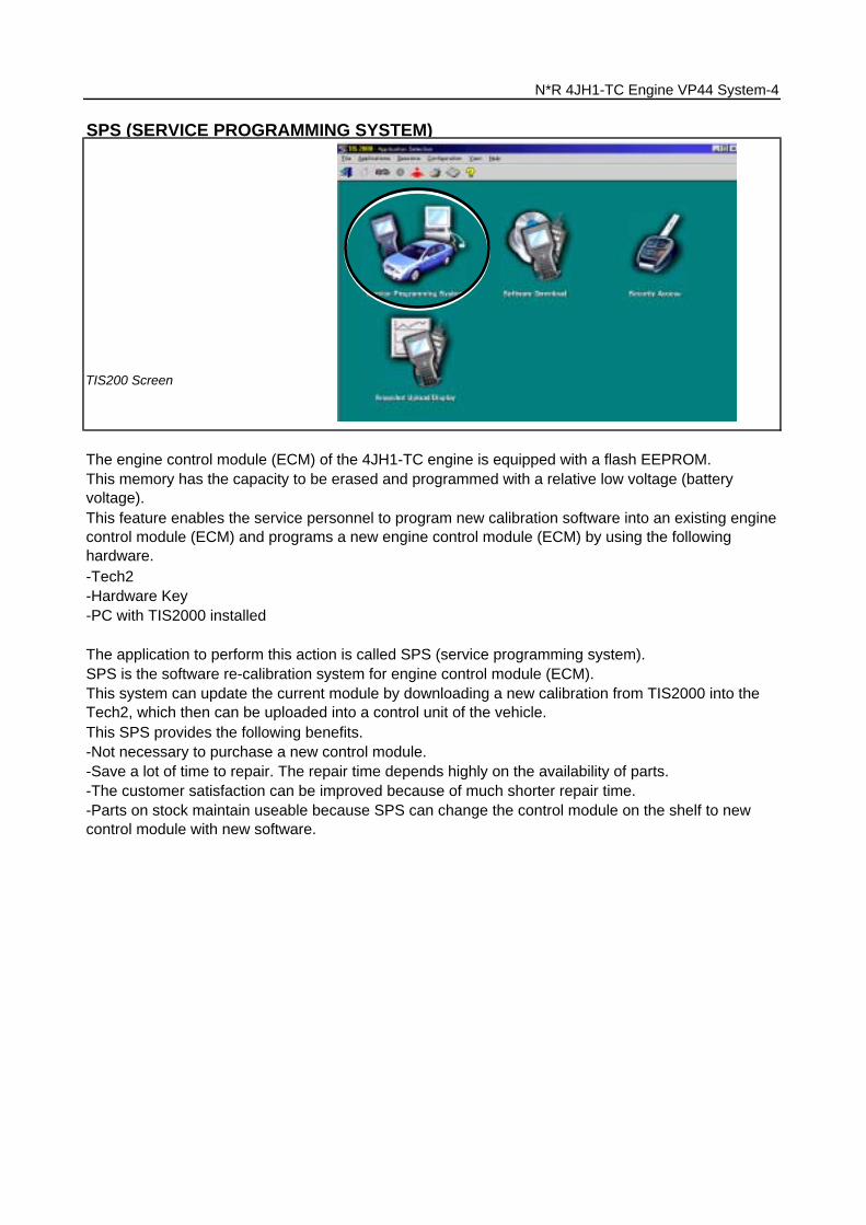
-Not necessary to purchase a new control module.-Save a lot of time to repair. The repair time depends highly on the availability of parts.-The customer satisfaction can be improved because of much shorter repair time.-Parts on stock maintain useable because SPS can change the control module on the shelf to newcontrol module with new software.
The application to perform this action is called SPS (service programming system).SPS is the software re-calibration system for engine control module (ECM).This system can update the current module by downloading a new calibration from TIS2000 into theTech2, which then can be uploaded into a control unit of the vehicle.This SPS provides the following benefits.
This feature enables the service personnel to program new calibration software into an existing enginecontrol module (ECM) and programs a new engine control module (ECM) by using the followinghardware.-Tech2-Hardware Key-PC with TIS2000 installed
SPS (SERVICE PROGRAMMING SYSTEM)
TIS200 Screen
The engine control module (ECM) of the 4JH1-TC engine is equipped with a flash EEPROM.This memory has the capacity to be erased and programmed with a relative low voltage (batteryvoltage).
N*R 4JH1-TC Engine VP44 System-4

The pump control unit (PSG) receives signals from the sensors inside the pump to determine the camring rotation angle, the pump speed and the fuel temperature .These values are then compared to the desired values sent by the engine control module (ECM) suchas the desired injection timing and the desired fuel injection quantity.
-Fuel Cutoff solenoid valve signal (MAB signal) (ECM terminal 105)
The information exchange between the two control modules takes place via two means.-Via analogue signal leads-Via the CAN-bus
The analogue signal leads are used to exchange the following information.
-Pump Control Unit (PSG) = Pumpen Steuer Great (German)
-Engine speed signal (ECM terminal 91)-Pump Speed (ECM terminal 105)
A Microprocessor then determines the operating conditions and calculates set values for optimumrunning.The interchange of data between the engine control module (ECM) and the pump control unit (PSG) isperformed via a CAN-bus system. The abbreviation CAN stands for Controller Area Network. Byhaving two separate control modules, the high pressure solenoid valve. This prevents the discharge ofany disturbing signals.
The engine control module (ECM) processes all engine data and data regarding the surroundingenvironment received from external sensors to perform any engine side adjustments.Maps for both are encoded in both control units. The control units input circuit process sensor data.
N*R 4JH1-TC Engine VP44 System-5
DATA EXCHANGE BETWEEN CONTROL MODULE
The radial plunger distributor type injection pump uses two control modules to execute full control ofthe engine management system.-Engine Control Module (ECM)
Self Diagnosis / Interface / Signal
To High Pressure Solenoid
Engine Speed
Injection Timing
Accelerator Pedal
Injection Quantity
Intake Air Temperature
Response Signal
Mass Air Flow
Additional Signal
Others
Additional Operations To Timing Control Valve (TCV)
EngineControlModule(ECM)
Cam Ring Rotational Angle Fuel Temperature
High Pressure Solenoid Valve Pump Control Fuel Injection Unit (Mechanical) (PSG)
Timing Device

The MAB signal wire is used for two purposes.-As a reference for the engine control module (ECM) for the pump speed (back up for the CKPsensor).-To turn Off the engine.
MAB in this case, refers to the German abbreviation Magnet ventil ABschaltung that stands for highpressure solenoid valve cut off.
The analogue CKP sensor signal is converted by the ECM into a square wave signal.
N*R 4JH1-TC Engine VP44 System-6
When the key switch is turned On, the engine control module (ECM) supplies a pulse on the MABsignal wire.The pulse is used by the pump control unit (PSG) to perform a self-test and determine whether:-the end-stage to control the high pressure solenoid valve works properly.-the fuel cutoff solenoid valve itself works properly.When the key switch is turned Off, the engine control module (ECM) supplies a 12 V pluses to theMAB signal wire. This pulse is the command for the pump control unit (PSG) to turn Off the engine.
The fuel cutoff solenoid valve signal is also referred to as MAB signal.
The engine speed signal is sent from the ECM to PSG based on the input from the crank shaftposition (CKP) sensor.
CKP Sensor Signal (Sensor to ECM) CH1 0V
TDC Signal (ECM to PSG) CH2 0V
Measurement Terminal: CH1: 90(+) / CH2: 91(+) 2(-) Measurement Scale: CH1: 20V/div / CH2: 20V/div 500 micro s/div Measurement Condition: Approximately 2000rpm
0V
On Off Measurement Terminal: CH1: 105(+) 2(-) Measurement Scale: CH1: 10V/div / CH2: 20V/div 500 ms/div

Once the engine is running, the MAB signal wire supplies above signal.
N*R 4JH1-TC Engine VP44 System-7
High Pressure Solenoid Operating Signal (PSG to Solenoid) CH1 0V
MAB Signal (PSG to ECM) CH2 0V
TDC Signal (ECM to PSG) CH3 0V
Measurement Terminal: CH1: Solenoid (+) / CH2: 105 (+) / CH3: 91(-) 2 (-) Measurement Scale: CH1: 20V/div / CH2: 200mV/div / CH3: 5V 5ms/div Measurement Condition: Approximately 2000rpm

DTC InformationCode Symptom
CodeDTC Name Fail-Safe (Back-up)
P0215 A Fuel Cutoff Solenoid ValveMalfunction
1. MAB (fuel cutoff solenoid valve) isoperated.2. Desired injection quantity becomes0mg/strk.
B Fuel Cutoff Solenoid Valve CircuitHigh Input
Engine does not start.
C Fuel Cutoff Solenoid Valve AlwaysActive
1. MAB (fuel cutoff solenoid valve) isoperated.2. Desired injection quantity becomes0mg/strk.
D Fuel Cutoff Solenoid ValveMalfunction
No fail-safe function.
-PSG status
The following signals are exchanged via the CAN-bus:From ECM to PSG
DTC Setting Condition
1. Ignition key switch off.2. Engine speed is below 1500rpm.3. Vehicle speed is below 1.5km/h.4. PSG (pump control unit)recognizes MAB (fuel cutoffsolenoid valve) signal from theECM, but the MAB could notoperate.
ECM does not command MAB (fuelcutoff solenoid valve) signal to thePSG (pump control unit), but PSGdetected MAB signal line circuit ishigh level.
-Fuel temperature-Pump camshaft speed-Cylinder identifier-Control pulse (actual injection quantity + actual injection timing)
-Desired injection quantity-Crankshaft position set point at beginning of fuel delivery
-Engine speed
From PSG to ECM
-Pump camshaft position set point at beginning of fuel delivery
1. Ignition key switch off.2. Engine speed is below 1500rpm.3. Vehicle speed is below 1.5km/h.4. PSG (pump control unit) does notrecognize MAB (fuel cutoff solenoidvalve) signal from the ECM.
1. Ignition key switch off.2. CAN controller does not operateBus-off.
N*R 4JH1-TC Engine VP44 System-8

Tech 2 InformationOrder Units Tech 2 Parameter3/37 rpm Pump Speed
12/37 deg. C /deg. F
Fuel Temperature
DTC InformationCode Symptom
CodeDTC Name Fail-Safe (Back-up)
P1173 7 Fuel Reduction Caused By HighFuel Temperature
PSG (pump control unit) controls fuelinjection quantity based on engine speedand fuel temperature.
A Fuel Reduction Caused By LowFuel Temperature
No fail-safe function.
P1345 A Camshaft Speed Malfunction No fail-safe function.
P1650 A CAN Device Offline MAB (fuel cutoff solenoid valve) isoperated.
B CAN Device Hang-up
P1651 A CAN Malfunction (PSG) 1. MAB (fuel cutoff solenoid valve) isoperated.2. Desired injection quantity becomes0mg/strk.
B CAN Receives Error
ExplanationThis displays injection pump speed. The injection speed is measured by ECMfrom the pump cam sensor.
The FT is measured by PSG from FT sensor. This data is changing by fueltemperature.
The PSG (pump control unit) isrecognized incorrect camshaftspeed signal.
CAN controller detects Bus-off orcanceling.
Fuel temperature is more than 100deg. C.
Excessive low fuel temperature isdetected.
N*R 4JH1-TC Engine VP44 System-9
CAN controller does not react underengine running.
The PSG (pump control unit) doesnot recognize CAN signal from theCAN controller.
The ECM does not read CAN signalfrom the PSG (pump control unit).
DTC Setting Condition

Pump Camshaft Speed Sensor
1. Pump Camshaft Speed Sensor
2. Sensor Wheel
3. Pump Camshaft Speed Sensor Retaining Ring
4. Flexible Connector Harness
5. Drive Shaft
When the drive shaft rotates, the pump camshaft speed sensor receives signal form the sensor wheel,and an electric pulse is sent through the flexible connecting harness to the pump control unit (PSG).From these signals the pump control unit (PSG) can determine the average pump speed and themomentary pump speed.The pump camshaft speed sensor is mounted to the cam ring. Thus, the relationship between the camring and the pump camshaft speed sensor signal is constant.
The pump camshaft speed sensor signal is utilized for the following purposes.
To calculate the actual speed of the fuel injection pump.To determine the actual timing plunger position.
The fuel injection quantity metering is performed by high pressure solenoid valve in the injectionpump. And it is determined depends on control duration of the high pressure solenoid valve and pumpcamshaft angular position.
11. Pressure Delivery Angle
PRINCIPLE OF FUEL QUANTITY METERING & INJECTION TIMING
1. Pump Camshaft Sensor Signal
3. High Pressure Solenoid Control Pulse
4. High Pressure Solenoid Needle Valve Lift
To determine the momentary angular position of the cam ring.
N*R 4JH1-TC Engine VP44 System-10
2. Crankshaft Position Sensor Signal
11. Effective Stroke
8. High Pressure Solenoid Valve Open
9. Start of Pressure Delivery
10. End of Pressure Delivery
5. Cam Lift (Cam Profile)
6. Pulse Count
7. High Pressure Solenoid Valve Close
6
7 8
9 10
12
11
2
4
3
1
5

High Pressure Solenoid Valve
1. Valve Needle
2. Magnet Anchor
3. Coil
4. High Pressure Passage
When current from the pump control unit (PSG) flows to the high pressure solenoid valve coil, themagnet anchor (a movable iron core) pushes the valve needle, toward the valve seat.
Fuel injection quantity control is performed from the beginning of pressure delivery at the beginning ofcam lift until the high pressure solenoid valve opens at the end of pressure delivery.
The pump camshaft sensor signal has a tooth gap, and the crankshaft position (CKP) sensor on theflywheel housing is used as a reference signal of engine top dead center (TDC) for the start timing offuel delivery or injection which is to be set.
This interval is called the pressure delivery interval. Accordingly, the interval that the high pressuresolenoid valve is closed determines the fuel injection quantity (high pressure fuel supply ends whenthe high pressure solenoid valve opens).
N*R 4JH1-TC Engine VP44 System-11
The pressure of the fuel in the high pressure passage is rapidly increased by radial plunger lift, andthe high pressure fuel is delivered through the constant pressure valve (CPV) to the nozzle holderassembly and is injected into the engine cylinder.
When the valve seat is completely closed by the valve needle, the way, of the fuel in the high pressurepassage to the low pressure circuit is closed.
-Cam Ring Angle Sensor -Pump Speed Wheel -Timer Position
PumpControl
Unit(PSG)
PumpCamshaft
Speed Sensor

1. Valve Needle
2. Coil
Timing Control Valve (TCV)
12. Timing Control Valve (TCV)
The timing plunger is connected to the cam ring by a ball pin. Axial movement of the timing plunger istransferred to the cam ring in the form of rotational movement. Movement to the right of the timingplunger (to the spring side) advances injection timing.
8. Ball Pin
N*R 4JH1-TC Engine VP44 System-12
The pressure of the fuel fed from the feed pump is adjusted in accordance with speed by theregulating valve. This delivery pressure acts on the hydraulic stopper's annular chamber as controlpressure.The chamber pressure of the annular chamber is controlled by the timing control valve (TCV).
9. Annular Chamber
10. Hydraulic Stopper
11. Return Passage
6. Inlet
7. Fuel Suction
1. Cam Ring
2. Servo Valve
3. Timer Piston
4. Outlet
5. Feed Pump
When the fuel injection quantity demanded by the engine is reached, the current to the coil is cut andthe valve needle re-opens the valve seat.As a result of this, a path is opened for the fuel in the high pressure passage to the low pressurecircuit and the pressure decreases. With a decrease in injection pressure the nozzle closes andinjection ends.

1. Coil
2. From Annular Chamber
3. To Feed Pump
4. Orifice
5. Valve Needle
Tech 2 InformationOrder Units Tech 2 Parameter7/37 mg/stk Desired Injection Quantity
8/37 mg/stk Injection Quantity
9/37 °CA Desired Fuel Injection Start
10/37 °CA Actual Injection Start
Consequently, the pressure of the annular chamber decreases and the hydraulic stopper is moved tothe retard side.
When control current flows to the timing control valve (TCV) coil, the valve needle opens and the fuelannular chamber flows through the orifice to the feed pump inlet.
ExplanationThis displays desired value from the ECM. The ECM compensates for fuelrate to basic rate.
This displays actual fuel quantity. The PSG controls high pressure solenoidvalve to meet commanded value from the ECM.
This displays desired injection timing from the ECM. The ECM compensatesfor fuel injection timing by throttle position and various sensor signal.
This displays calculated actual injection timing based on CKP signal andpump cam signal. The PSG controls TCV duty ratio to meet desired injectiontiming from the ECM.
The engine control module (ECM) contains characteristic maps of the start of injection, correspondingto engine operating conditions (engine load, engine speed and engine coolant temperature).The pump control unit (PSG) is constantly comparing the set start of injection timing and the actualstart of injection timing. If there is a difference, the timing control valve (TCV) is controlled by the dutyratio. (The actual start of injection timing is determined from the pump camshaft speed sensor.)
N*R 4JH1-TC Engine VP44 System-13
Engine Load
Engine Speed
Engine CoolantTemperature
EngineControlModule(ECM)
PumpControl
Unit(PSG)
Pump CamshaftSpeed Sensor
TimingControlValve(TCV)

DTC InformationCode Symptom
CodeDTC Name Fail-Safe (Back-up)
P0216 A Injection Timing Control CircuitMalfunction (Timer Deviation)
Fuel injection quantity is reduced.
B Injection Timing Control CircuitMalfunction (Timer Fluctuation)
P0251 6 Injection Pump Malfunction 1. MAB (fuel cutoff solenoid valve) isoperated.2. Desired injection quantity becomes0mg/strk.
7 Injection Pump Malfunction
9 Injection Pump Malfunction
A Injection Pump Malfunction Fuel injection quantity is reduced.
B Injection Pump Malfunction No fail-safe function.
D Injection Pump Malfunction
E Injection Pump Malfunction 1. MAB (fuel cutoff solenoid valve) isoperated.2. Desired injection quantity becomes0mg/strk.
P1630 A Fuel Injection Quantity CircuitMalfunction
Fuel injection quantity is reduced.
B Fuel Injection Quantity CircuitMalfunction
1. MAB (fuel cutoff solenoid valve) isoperated.2. Desired injection quantity becomes0mg/strk.
PSG (pump control unit) could notmeasure the high pressure solenoidvalve drive voltage.
ECM could not accept PSG (pumpcontrol unit) message.
The PSG (pump control unit)detects high pressure solenoid valvecontrol circuit malfunction due tohigh current.
The PSG (pump control unit)detects high pressure solenoid valvecontrol circuit malfunction due tocontinuous current.
1. No pump camshaft speed sensorerror.2. No CKP sensor error.3. Difference of engine speed anddoubled pump camshaft speed ismore than 800rpm.
No pump map programmed in thePSG (pump control unit) or PSGmalfunction.
EEPROM or A/D convertermalfunction in the PSG (pumpcontrol unit).
PSG (pump control unit) recognizedhigh pressure solenoid valve drivecircuit error.
1. Engine speed is more than700rpm.2. Fuel injection quantity is morethan 4mg/stk.3. Deviation of actual injectiontiming and desired injection timing ismore than +3 deg. CA or -6 deg.CA for 8 seconds.
1. Engine speed is more than2014rpm.2. Fluctuation of actual injectiontiming is more than +-5.2 deg. CA.
1. No pump camshaft speed sensorerror.2. High pressure solenoid valvecontrol pulse width does not matchwith desired fuel injection quantity.
DTC Setting Condition
N*R 4JH1-TC Engine VP44 System-14

N*R 4JH1-TC Engine VP44 System-15
ECM WIRING SCHEME

View Looking Into ECM Case
PinNo.
B/BoxNo.
Pin FunctionWireColor
Key SW Off Key SW On Engine IdleEngine
2000rpmECM
ConnectionRange (+) (-)
1 1 ECM Ground BLKContinuity
with ground- - - Disconnect Ohm 1 GND
2 2 ECM Ground BLKContinuity
with ground- - - Disconnect Ohm 2 GND
3 3 Battery Power SupplyBLU/RED
Less than 1V Connect DC V 3 GND
25 25 No Connection - - - - - - - - -
26 26 No Connection - - - - - - - - -
27 27Engine Speed Output (ToTacho Meter)
LGN - -Approx. 23Hzby wave form
or approx. 7.5V
Approx. 66Hzby wave form
or approx. 7.5VConnect AC V 27 GND
28 28 No Connection - - - - - - - - -
29 29 No Connection - - - - - - - - -
30 30 Brake Switch 1 Signal GRN Less than 1V Connect DC V 30 GND
31 31 Clutch Switch Signal YEL Less than 1V Connect DC V 31 GND
32 32Exhaust Brake Cut Signal(ABS C/U No.8 to ECM)
LGN/WHT
- - - - - - - -
33 33 A/C ON Signal RelayGRN/YEL
Connect DC V 33 GND
34 34 No Connection - - - - - - - - -
35 35 To Data Link Connector No. 7 YEL - - - - Connect DC V 35 GND
36 36 No Connection - - - - - - - - -
37 37 No Connection - - - - - - - - -
38 38Throttle Position Sensor (TPS)Output Signal
GRN/ORG
Less than 1V Approx. 1.4V Connect DC V 38 49
39 39Key Switch Input Signal ViaGenerator Fuse
WHT Less than 1V Connect DC V 39 GND
40 40 Exhaust Brake Magnetic Valve LGN Less than 1V Connect DC V 40 GND
41 41 A/C Compressor RelayWHT/GRN
Less than 1V 10-14V Connect DC V 41 GND
42 42 Check Engine LampGRN/YEL
Less than 1V Connect DC V 42 GND
Battery voltage
Pedal is not stepped on: Less than 1VPedal is stepped on: 10-14V
Pedal is not stepped on: 10-14VPedal is stepped on: Less than 1V
A/C request switch is turned on: 10-14V A/C requestswitch is turned off: Less than 1V
Less than 1V
10-14V
A/C comp. is operated: Less than 1VA/C comp. is not operated: 10 - 14V
ECM CONNECTOR PIN ASSIGNMENT & OUTPUT SIGNAL
N*R 4JH1-TC Engine VP44 System-16
Magnetic Valve is turned on: Less than 1VMagnetic Valve is turned off: 10-14V
Lamp is turned on: Less than 1VLamp is turned off: 10-14V
Less than 1V
Signal or Continuity Tester Position

PinNo.
B/BoxNo.
Pin FunctionWireColor
Key SW Off Key SW On Engine IdleEngine
2000rpmECM
ConnectionRange (+) (-)
43 43 Glow LampORG/BLU
Less than 1V Connect DC V 43 GND
44 44 No Connection - - - - - - - - -
45 45 To Data Link Connector No. 6 BLU Less than 1V Connect DC V 45 GND
46 46 QWS SwitchBRN/RED
Less than 1V Connect DC V 46 GND
47 47 No Connection - - - - - - - - -
48 48 No Connection - - - - - - - - -
49 49Throttle Position Sensor (TPS)Ground
BLK/GRN
Idle: Approx. 0.6Kohm / WOT:
Approx. 3.5K ohm- - - Disconnect Ohm 38 49
50 50 No Connection - - - - - - - - -
51 51 No Connection - - - - - - - - -
52 52 No Connection - - - - - - - - -
53 53 No Connection - - - - - - - - -
54 54 No Connection - - - - - - - - -
55 55 No Connection - - - - - - - - -
56 56 No Connection - - - - - - - - -
57 57Throttle Position Sensor (TPS)Power Supply
RED/GRN
Less than 1V Connect DC V 57 49
58 58 ECM RelayBLU/BLK
10-14V Connect DC V 58 GND
59 59 QWS Indicator Lamp BRN Less than 1V Connect DC V 59 GND
60 60 Exhaust Brake LampGRN/RED
Less than 1V Connect DC V 60 GND
61 61 No Connection - - - - - - - - -
62 62Exhaust Brake Cut Signal(ECM to ABS C/U No.7)
LGN/BLK
- - - - - - - -
63 63 No Connection - - - - - - - - -
64 64 Exhaust Brake SwitchLGN/BLU
Less than 1V Connect DC V 64 GND
65 65 Brake Switch 2 SignalWHT/BLK
Less than 1V Connect DC V 65 GND
66 66 No Connection - - - - - - - - -
67 67 No Connection - - - - - - - - -
68 68 Vehicle Speed Sensor (VSS)YEL/GRN
- Connect AC V 68 GND
Pedal is not stepped on: 10-14VPedal is stepped on: Less than 1V
Less than 1V
Lamp is turned on: Less than 1VLamp is turned off: 10-14V
Less than 1V
Less than 1V
10-14V
Approx. 14.5Hz by wave form or approx.6.0V at vehicle speed 20km/h
Approx. 5V
Less than 1V
SW is turned on: 10-14VSW is turned off: Less than 1V
Signal or Continuity Tester Position
N*R 4JH1-TC Engine VP44 System-17
PinNo.
B/BoxNo.
Pin FunctionWireColor
Key SW Off Key SW On Engine IdleEngine
2000rpmECM
ConnectionRange (+) (-)
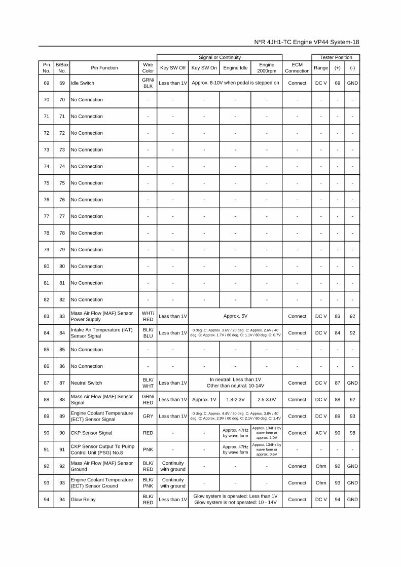
69 69 Idle SwitchGRN/BLK
Less than 1V Connect DC V 69 GND
70 70 No Connection - - - - - - - - -
71 71 No Connection - - - - - - - - -
72 72 No Connection - - - - - - - - -
73 73 No Connection - - - - - - - - -
74 74 No Connection - - - - - - - - -
75 75 No Connection - - - - - - - - -
76 76 No Connection - - - - - - - - -
77 77 No Connection - - - - - - - - -
78 78 No Connection - - - - - - - - -
79 79 No Connection - - - - - - - - -
80 80 No Connection - - - - - - - - -
81 81 No Connection - - - - - - - - -
82 82 No Connection - - - - - - - - -
83 83Mass Air Flow (MAF) SensorPower Supply
WHT/RED
Less than 1V Connect DC V 83 92
84 84Intake Air Temperature (IAT)Sensor Signal
BLK/BLU
Less than 1V Connect DC V 84 92
85 85 No Connection - - - - - - - - -
86 86 No Connection - - - - - - - - -
87 87 Neutral SwitchBLK/WHT
Less than 1V Connect DC V 87 GND
88 88Mass Air Flow (MAF) SensorSignal
GRN/RED
Less than 1V Approx. 1V 1.8-2.3V 2.5-3.0V Connect DC V 88 92
89 89Engine Coolant Temperature(ECT) Sensor Signal
GRY Less than 1V Connect DC V 89 93
90 90 CKP Sensor Signal RED - -Approx. 47Hzby wave form
Approx. 134Hz bywave form orapprox. 1.0V
Connect AC V 90 98
91 91CKP Sensor Output To PumpControl Unit (PSG) No.8
PNK - -Approx. 47Hzby wave form
Approx. 134Hz bywave form orapprox. 0.6V
- - - -
92 92Mass Air Flow (MAF) SensorGround
BLK/RED
Continuitywith ground
- - - Connect Ohm 92 GND
93 93Engine Coolant Temperature(ECT) Sensor Ground
BLK/PNK
Continuitywith ground
- - - Connect Ohm 93 GND
94 94 Glow RelayBLK/RED
Less than 1V Connect DC V 94 GND
N*R 4JH1-TC Engine VP44 System-18
Approx. 8-10V when pedal is stepped on
Approx. 5V
In neutral: Less than 1VOther than neutral: 10-14V
Signal or Continuity Tester Position
0 deg. C: Approx. 3.6V / 20 deg. C: Approx. 2.6V / 40deg. C: Approx. 1.7V / 60 deg. C: 1.1V / 80 deg. C: 0.7V
0 deg. C: Approx. 4.4V / 20 deg. C: Approx. 3.8V / 40deg. C: Approx. 2.9V / 60 deg. C: 2.1V / 80 deg. C: 1.4V
Glow system is operated: Less than 1VGlow system is not operated: 10 - 14V

PinNo.
B/BoxNo.
Pin FunctionWireColor
Key SW Off Key SW On Engine IdleEngine
2000rpmECM
ConnectionRange (+) (-)
95 95 Intake Throttle VSVLGN/WHT
Less than 1V Connect DC V 95 GND
96 96 No Connection - - - - - - - - -
97 97 EGR EVRVBLK/ORG
- - - - - -
98 98 CKP Sensor Ground WHTContinuity
with ground- - - Connect Ohm 98 GND
99 99CAN (Controller Area Network)to PSG No.1
BLU - - - - - - - -
100 100CAN (Controller Area Network)to PSG No.2
YEL - - - - - - - -
101 101 CKP Sensor Shield Line BLKContinuity
with ground- - - Connect Ohm 101 GND
102 102 No Connection - - - - - - - - -
103 103 No Connection - - - - - - - - -
104 104 No Connection - - - - - - - - -
105 105Solenoid Valve Shut Off (MAB)Output Signal to PSG No.5
ORG - - - - - - - -
View Looking Into PSG Case
PinNo.
B/BoxNo.
Pin FunctionWireColor
Key SW Off Key SW On Engine IdleEngine
2000rpmECM & PSGConnection
Range (+) (-)
1 99CAN (Controller Area Network)to ECM No.99
REDContinuity
between ECM &PSG
- - - Disconnect Ohm 199
(ECM)
2 100CAN (Controller Area Network)to ECM No.100
WHTContinuity
between ECM &PSG
- - - Disconnect Ohm 2100
(ECM)
3 - No Connection - - - - - - - - -
4 - No Connection - - - - - - - - -
5 105Solenoid Valve Shut Off (MAB)Output Signal to ECM No.105
ORGContinuity
between ECM &PSG
- - - Disconnect Ohm 5105
(ECM)
6 - Ground BLKContinuity with
ground - - - Disconnect Ohm 6 GND
7 3 Battery Power SupplyBLU/RED
Less than 1V Disconnect Ohm 7 GND
8 91CKP Sensor Output ECMNo.91 to Pump Control Unit(PSG)
PNKContinuity
between ECM &PSG
- - - Disconnect Ohm 891
(ECM)
9 - No Connection - - - - - - - - -
10-14V
Tester PositionSignal or Continuity
Approx. 140Hz by wave formwhen EVRV is operated
PSG CONNECTOR PIN ASSIGNMENT & OUTPUT SIGNAL
VSV is operated: Less than 1VVSV is not operated: 10 - 14V
Signal or Continuity
N*R 4JH1-TC Engine VP44 System-19
Tester Position
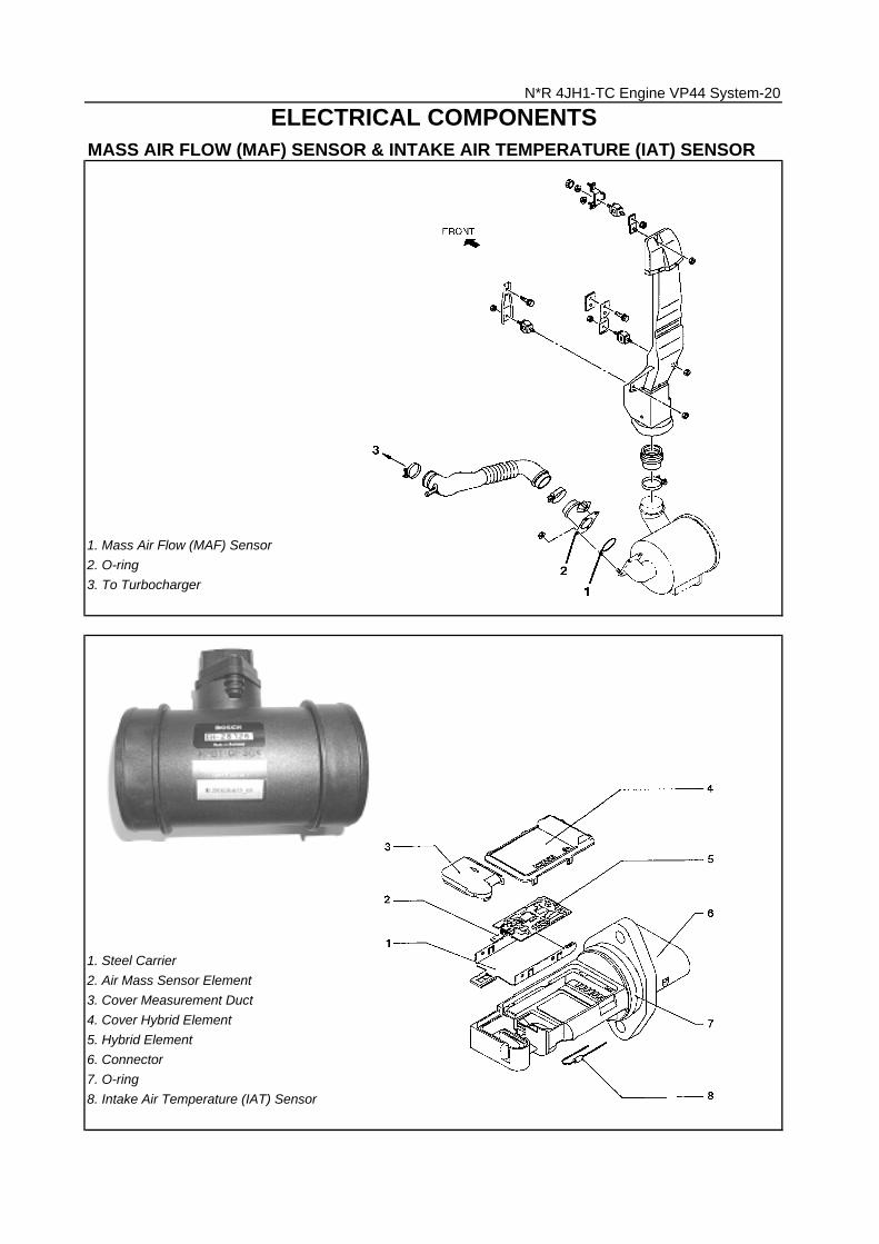
MASS AIR FLOW (MAF) SENSOR & INTAKE AIR TEMPERATURE (IAT) SENSOR
1. Mass Air Flow (MAF) Sensor
2. O-ring
3. To Turbocharger
1. Steel Carrier
2. Air Mass Sensor Element
3. Cover Measurement Duct
4. Cover Hybrid Element
5. Hybrid Element
6. Connector
7. O-ring
8. Intake Air Temperature (IAT) Sensor
N*R 4JH1-TC Engine VP44 System-20
ELECTRICAL COMPONENTS

The sensor element is only supplied as an assembly with the housing.The measuring element is fitted to the housing with two screws but is not separately replaceable.
The mass air flow (MAF) sensor uses a hot film element to determine the amount of air flowing intothe engine.The mass air flow (MAF) sensor assembly consist of a mass air flow (MAF) sensor element and anintake air temperature sensor that are both exposed to the air flow to be measured.The mass air flow (MAF) sensor element measures the partial air mass through a measurement ducton the sensor housing.
The mass air flow (MAF) sensor is part of the intake air system.It is fitted between the air cleaner and turbocharger and measure the mass air flowing into theengine.
Using calibration, there is an extrapolation to the entire mass air flow to the engine.
N*R 4JH1-TC Engine VP44 System-21
The characteristic of the mass air flow (MAF) sensor are displayed in the graph. These voltage canbe measured on terminal 88 of the engine control module (ECM).
Characteristic of MAF Sensor Output (Reference)
0
0.5
1
1.5
2
2.5
3
3.5
4
4.5
5
0 700 1000 1500 2000 2500 3000 3500 4000Engine Speed (rpm) (Tech2 reading)
Outp
ut V
olta
ge (
V)
(DV
Mre
adin
g)
(Dotted li
ne)
0
100
200
300
400
500
600
700
800
900
1000(Condition: No engine load, ECT reading approx. 80 deg. C)
Ca
lcu
late
d A
ir F
low
(m
g/s
trk)
(Te
ch2
re
ad
ing
) (S
olid
lin
e)
Characteristic of IAT Sensor -Reference-
10
100
1000
10000
100000
-30 -20 -10 0 10 20 30 40 50 60 70 80 90 100 110Intake Air Temp. (deg. C) (Tech2 Reading)
Re
sist
an
ce (
oh
m)
(So
lidL
ine
)
0
0.5
1
1.5
2
2.5
3
3.5
4
4.5
5
Ou
tpu
t V
olta
ge
(V
) (D
ott
ed
Lin
e)
Intake Air Temp.(deg. C)
(Tech2 Reading)
OutputVoltage (V)(Approx.)
Resistance(ohm)
(Approx.)
-20 4.3 13660
0 3.6 5430
20 2.6 2433
40 1.7 1153
60 1.1 598
80 0.7 334
100 0.4 203.5

The values for the intake air temperature (IAT) sensor can be measured on terminal 84.20 deg. C: Approximately 2.6V30 deg. C: Approximately 2.1V40 deg. C: Approximately 1.7V
1. IAT Sensor Output to ECM Terminal 84
2. Voltage Supply from ECM Fuse via ECM Relay
3. IAT Sensor & MAF Sensor Ground to ECM Terminal 92
4. MAF Sensor +5V Supply from ECM Terminal 83
5. MAF Sensor Signal to ECM Terminal 88
N*R 4JH1-TC Engine VP44 System-22
The IAT sensor is a thermistor. A temperature changes the resistance value. And it changes voltage.In other words it measures a temperature value. Low air temperature produces a high resistance.
The ECM supplies 5 volts signal to the IAT sensor through resisters in the ECM and measures thevoltage. The signal voltage will be high when the air temperature is cold, and it will be low when theair temperature is hot.
MAF & IAT Sensor Pin Assignment(View Looking Sensor Side Connector)
1
2
3
4
5

Tech 2 InformationOrder Units Tech 2 Parameter5/37 mg/strk Mass Air Flow
13/37 deg. C Intake Air Temperature
DTC InformationCode Symptom
CodeDTC Name Fail-Safe (Back-up)
P0100 7 Mass Air Flow (MAF) SensorVoltage Supply Circuit High Input
9 Mass Air Flow (MAF) SensorVoltage Supply Circuit Low Input
B Mass Air Flow (MAF) SensorOutput Circuit Low Input
C Mass Air Flow (MAF) SensorOutput Circuit High Input
P0110 1 Intake Air Temperature (IAT)Sensor Circuit High Input
ECM use 0 deg. C conditions assubstitute.
2 Intake Air Temperature (IAT)Sensor Circuit Low Input
This displays intake air amount. The mass air flow is measured by ECMfrom the MAF sensor output voltage.
IAT sensor output voltage is below0.3V.
1. Engine speed is between 600rpmand 5000rpm.2. MAF sensor output is more than1784mg/strk.
IAT sensor output voltage is morethan 4.7V.
N*R 4JH1-TC Engine VP44 System-23
MAF sensor power supply voltage ismore than 5.2V.
MAF sensor power supply voltage isbelow 4.6V.
1. Engine speed is between 600rpmand 5000rpm.2. MAF sensor output is below -33.7mg/strk.
ECM uses mass air flow 1600mg/strk& EGR 10% conditions as substitute.
DTC Setting Condition
Explanation
The IAT is measured by ECM from IAT sensor output voltage. This data ischanging by intake air temperature.

20 deg. C: Approximately 3.8V60 deg. C: Approximately 2.1V80 deg. C: Approximately 1.4V
The signal from the engine coolant temperature (ECT) sensor can be measured using a multi meterby performing a measurement on terminal 89 of the engine control module (ECM).
N*R 4JH1-TC Engine VP44 System-24
2. Thermo Unit For Water Temperature Gauge
The ECT sensor is a thermistor. A temperature changes the resistance value. And it changesvoltage. In other words it measures a temperature value. It is installed on the coolant stream. Lowcoolant temperature produces a high resistance.The ECM supplies 5 volts signal to the ECT sensor through resisters in the ECM and measures thevoltage. The signal voltage will be high when the engine temperature is cold, and it will be low whenthe engine temperature is hot. The ECM uses to this value, and calculates fuel injection timing,injection volume and an EGR control.
1. Engine Coolant Temperature (ECT) Sensor
ENGINE COOLANT TEMPERATURE (ECT) SENSOR
2
1
Characteristic of ECT Sensor -Reference-
10
100
1000
10000
100000
-30 -20 -10 0 10 20 30 40 50 60 70 80 90 100 110 120 130Engine Coolant Temp (deg. C) (Tech2 Reading)
Re
sist
an
ce (
oh
m)
(So
lidL
ine
)
0
0.5
1
1.5
2
2.5
3
3.5
4
4.5
5
Ou
tpu
t V
olta
ge
(V
) (D
ott
ed
Lin
e)
Coolant Temp.(deg. C)
(Tech2 Reading)
OutputVoltage (V)(Approx.)
Resistance(ohm)
(Approx.)
-20 4.7 16100
0 4.4 5760
20 3.8 2370
40 2.9 1080
60 2.1 537
80 1.4 290
100 0.88 161
120 0.55 99.5

1. ECT Sensor Output to ECM Terminal 89
2. ECT Sensor Ground to ECM Terminal 93
Tech 2 InformationOrder Units Tech 2 Parameter11/37 deg. C Coolant Temperature
DTC InformationCode Symptom
CodeDTC Name Fail-Safe (Back-up)
P0115 1 Engine Coolant Temperature (ECT)Sensor Circuit High Input
2 Engine Coolant Temperature (ECT)Sensor Circuit Low Input
N*R 4JH1-TC Engine VP44 System-25
ECT sensor output voltage is morethan 4.7V.
ECT sensor output voltage is below0.3V.
DTC Setting Condition
1. ECM uses fuel temperature assubstitute.2. ECM uses 60 deg. C condition forinjection timing control.3. ECM uses -15 deg. C condition forglow time control.
The ECT is measured by ECM from ECT sensor output voltage. This data ischanging by coolant temperature. When the engine is normally warmupped, this data displays approximately 80 deg. C.
Explanation
ECT Sensor Pin Assignment(View Looking Sensor Side Connector)
1
2
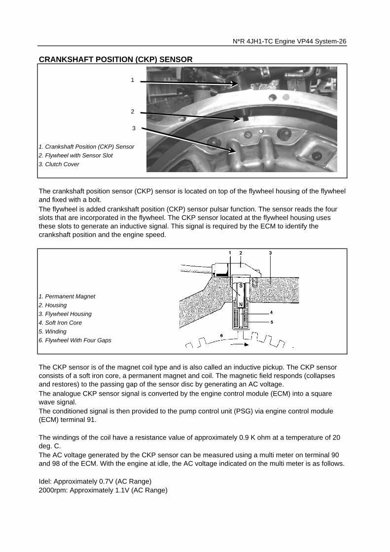
1. Permanent Magnet
2. Housing
3. Flywheel Housing
4. Soft Iron Core
5. Winding
6. Flywheel With Four Gaps
Idel: Approximately 0.7V (AC Range)2000rpm: Approximately 1.1V (AC Range)
N*R 4JH1-TC Engine VP44 System-26
1. Crankshaft Position (CKP) Sensor
2. Flywheel with Sensor Slot
3. Clutch Cover
The crankshaft position sensor (CKP) sensor is located on top of the flywheel housing of the flywheeland fixed with a bolt.
CRANKSHAFT POSITION (CKP) SENSOR
The flywheel is added crankshaft position (CKP) sensor pulsar function. The sensor reads the fourslots that are incorporated in the flywheel. The CKP sensor located at the flywheel housing usesthese slots to generate an inductive signal. This signal is required by the ECM to identify thecrankshaft position and the engine speed.
The windings of the coil have a resistance value of approximately 0.9 K ohm at a temperature of 20deg. C.
The conditioned signal is then provided to the pump control unit (PSG) via engine control module(ECM) terminal 91.
The AC voltage generated by the CKP sensor can be measured using a multi meter on terminal 90and 98 of the ECM. With the engine at idle, the AC voltage indicated on the multi meter is as follows.
The analogue CKP sensor signal is converted by the engine control module (ECM) into a squarewave signal.
The CKP sensor is of the magnet coil type and is also called an inductive pickup. The CKP sensorconsists of a soft iron core, a permanent magnet and coil. The magnetic field responds (collapsesand restores) to the passing gap of the sensor disc by generating an AC voltage.
1
2
3

1. CKP Sensor (-) to ECM Terminal 98
2. CKP Sensor (+) to ECM Terminal 90
3. Shield Wire to ECM Terminal 101
N*R 4JH1-TC Engine VP44 System-27
CKP Sensor Pin Assignment(View Looking Sensor Side Connector)
1
2
3
CKP Sensor Signal (Sensor to ECM) CH1 0V
TDC Signal (ECM to PSG) CH2 0V
Measurement Terminal: CH1: 90(+) / CH2: 91(+) 2(-) Measurement Scale: CH1: 20V/div / CH2: 20V/div 500 micro s/div Measurement Condition: Approximately 2000rpm

Tech 2 InformationOrder Units Tech 2 Parameter1/37 rpm Engine Speed
DTC InformationCode Symptom
CodeDTC Name Fail-Safe (Back-up)
P0335 B Crankshaft Position Sensor CircuitMalfunction
When pump camshaft speed sensor isOK:ECM uses doubled pump camshaftspeed as substitute engine speed.When pump camshaft speed sensor isnot OK:1. MAB (fuel cutoff solenoid valve) isoperated.2. Desired injection quantity becomes0mg/strk.
D Crankshaft Position Sensor CircuitMalfunction
When pump camshaft speed sensor isOK:ECM uses doubled pump camshaftspeed as substitute engine speed.Other than pump camshaft speedsensor is OK:Fuel injection quantity is reduced.
E Engine Speed Input CircuitRange/Performance
When intermittent malfunction:1. MAB (fuel cutoff solenoid valve) isoperated.2. Desired injection quantity becomes0mg/strk.When preliminary malfunction:ECM uses doubled pump camshaftspeed as substitute engine speed.
P1335 A Engine Speed Output CircuitMalfunction
Fuel injection quantity is reduced.
The engine speed is measured by ECM from the CKP sensor.
1. Engine speed is more than665rpm.2. CKP sensor pulse width error.
1. No pump camshaft speed sensorerror.2. "Crankshaft Position SensorCircuit Malfunction (Symptom CodeB)" is not stored.3. Engine speed is 0rpm.4. Doubled pump camshaft speed ismore than 50rpm.
In the idle, engine speed follows to the desired idle speed.
N*R 4JH1-TC Engine VP44 System-28
DTC Setting Condition
Engine speed is more than5700rpm.
The PSG (pump control unit) isrecognized defective engine speedsignal form the ECM.
Explanation

1. Pedal/Throttle Position Sensor (TPS)
2. Idle Switch
1. TPS +5V Supply Voltage from ECM Terminal 49
2. TPS Signal Output to ECM Terminal 38
3. TPS Ground to ECM Terminal 57
PEDAL/THROTTLE POSITION SENSOR (TPS)
The engine control module (ECM) calculates fuel delivery based on throttle valve angle.
The TPS is a potentiometer connected to throttle shaft on the throttle body. It is installed to the mainTPS and idle switch.The engine control module (ECM) monitors the voltage on the signal line and calculates throttleposition. As the throttle valve angle is changed when accelerator pedal moved. The TPS signal alsochanged at a moved throttle valve. As the throttle valve opens, the output increases so that theoutput voltage should be high.
N*R 4JH1-TC Engine VP44 System-29
TPS Pin Assignment(View Looking Sensor Side Connector)
1
2
3
1
2
Characteristic of TPS Output Signal (Reference)
0
1
2
3
4
5
0 5 10 15 20 25 30 35 40 45 50 55 60 65 70 75 80 85 90 95 100
Pedal/Throttle Angle (%) (Tech2 reading)
Ou
tpu
t V
olta
ge
(V
) (D
VM
re
ad
ing
)

Tech 2 InformationOrder Units Tech 2 Parameter4/37 % Accelerator Position Signal
15/37 Active/Inactive
Idle Switch
DTC InformationCode Symptom
CodeDTC Name Fail-Safe (Back-up)
P1120 1 Pedal/Throttle Position SensorCircuit High Input
ECM increases idle speed up to1400rpm.
2 Pedal/Throttle Position SensorCircuit Low Input
7 Pedal/Throttle Position SensorVoltage Supply Circuit High Input
9 Pedal/Throttle Position SensorVoltage Supply Circuit Low Input
D Pedal/Throttle Position SensorBrake Switch Error
E Pedal/Throttle Position Sensor IdlePosition Switch Error
Throttle position sensor outputvoltage is more than 4.9V.
When idle switch is tuned on, throttleposition sensor was more than 18%.
ExplanationThrottle position operating angle is measured by the ECM from throttleposition output voltage. This should display 0% at idle and 99 - 100% at fullthrottle.
Throttle position sensor outputvoltage is below 0.3V.
1. Engine speed is more than1700rpm.2. Throttle position sensor is morethan 18%.3. When brake pedal is depressedduring accelerator pedal isdepressing.
Throttle position sensor powersupply voltage is below 4.6V.
DTC Setting Condition
This displays operating status of the idle switch. This should display "Active"when the idle condition.
Throttle position sensor powersupply voltage is more than 5.2V.
N*R 4JH1-TC Engine VP44 System-30

1. VSS +12V Supply from Vehicle Speed Meter
2. VSS Ground to Vehicle Speed Meter
3. VSS Output Signal to Vehicle Speed Meter & ECM Terminal 68
Vehicle Speed Sensor (VSS)
N*R 4JH1-TC Engine VP44 System-31
VEHICLE SPEED SENSOR (VSS)
The VSS is a magnet rotated by the transmission output shaft. The VSS uses a hall element. Itinteracts with the magnetic field treated by the rotating magnet. It outputs pulse signal. The 12 voltsoperating supply from the "gauge back" fuse.The engine control module (ECM) calculates the vehicle speed by VSS.
VSS Pin Assignment(View Looking Sensor Side Connector)
1
2
3
0V
Measurement Terminal: 68(+) 1(-) Measurement Scale: 5V/div 50ms/div Measurement Condition: Approximately 20km/h

Tech 2 InformationOrder Units Tech 2 Parameter2/37 km/h Vehicle Speed
DTC InformationCode Symptom
CodeDTC Name Fail-Safe (Back-up)
P0500 1 Vehicle Speed Sensor Circuit HighInput
ECM uses vehicle speed 5km/hcondition as substitute.
A Vehicle Speed Sensor Input SignalFrequency Too High
ECM uses vehicle speed 5km/hcondition as substitute.
B Vehicle Speed Sensor IncorrectSignal
Fuel injection quantity is reduced.
Input signal frequency is too high.
1. Engine speed is more than3600rpm.2. Fuel injection quantity is morethan 41mg/stk.3. Vehicle speed is below 1.5km/h.
This displays vehicle speed. The vehicle speed is measured by ECM fromthe vehicle speed sensor.
N*R 4JH1-TC Engine VP44 System-32
DTC Setting Condition
Explanation
Vehicle speed is more than190km/h.

1. EGR EVRV
2. EGR Valve
-Engine speed-Injection quantity-Mass air flow-Intake air temperature-Coolant temperature-Barometric pressure
N*R 4JH1-TC Engine VP44 System-33
EGR (EXHAUST GAS RE-CIRCULATION)
5. Exhaust Manifold
The 4JH1-TC engine is equipped with the EGR cooler. The EGR cooler reduces the temperature ofthe air being drawn into the engine and the combustion temperature. This results in reducingnitrogen oxide (Nox) emissions.The amount of EGR is controlled by EVRV (electrical vacuum regulating valve) via the engine controlmodule (ECM) command signal depends on the following inputs.
6. Waste Gate
7. Fresh Air
8. Exhaust Gas
9. Turbocharger
1. EGR Valve
2. EGR Cooler
3. Intercooler
4. Intake Manifold
�����������������������������������������������������������������������������������������������������������������������������������������������������������������������������������������������������������������������������������������������������������������������������������������������������������������������������������������������������������������������������������������������������������������������������������������������������������������������������������������������������������������������������������������������������������������������������������������������������������������������������������������������������������������������������������������������������������������������������������������������������������������������������������������������������������������������������������������������������������������������������������������������������������������������������������������������������������������������������������������������������������������������������������������������������������������������������������������������������������������������������������������������������������������������������������������������������������������������������������������������������������������������������������������������������������������������������������������������������������������������������������������������������������������������������������������������������������������������������������������������������������������������������������������������������������������������������������������������������������������������������������������������������������������������������������������������������������������������������������������������������������������������������������������������������������������������������������������������������������������������������������������������������������������������������������������������������������������������������������������������������������������������������������������������������������������������������������������������������������������������������������������������������������������������������������������������������������������������������������������������������������������������������������������������������������������������������������������������������������������������������������������������������������������������������������������������������������������������������������������������������������������������������������������������������������������������������������������������������������������������������������������������������������������������������������������������������������������������������������������������������������������������������������������������������������������������������������������������������������������������������������������������������������������������������������������������������������������������������������������������������������������������������������������������������������������������������������������������������������������������������������������������������������������������������������������������������������������������������������������������������������������������������������������������������
2
1

1. EVRV Signal from ECM Terminal 97
2. EVRV +12V Supply from ECM Fuse via ECM Relay
The EVRV is shaped to control vacuum applied to the diaphragm chamber of the EGR valve basedon duty signal sent from the ECM. The duty ratio is the time that the EVRV is opened to onecooperate EVRV operating cycle. A duty ratio change of 70% to 10 % is EGR amount control.
The EVRV solenoid coil have a resistance value of approximately 14 ohm at a temperature of 20deg. C.
N*R 4JH1-TC Engine VP44 System-34
7.1ms 7.1ms
Time Time 0.7ms 6.4ms
Vo
ltage
Off duty 10% =EGR Pulse Ratio 10%
Vo
ltage
Off duty 70% =EGR Pulse Ratio 70%
EGR EVRV Pin Assignment(View Looking EVRV Side Connector)
1
2

Tech 2 Information
Order Units Tech 2 Parameter
31/37 % EGR Pulse Ratio
DTC InformationCode Symptom
CodeDTC Name Fail-Safe (Back-up)
P0400 3 Exhaust Gas Recirculation FlowExcessive Detected
Fuel injection quantity is reduced.
4 Exhaust Gas Recirculation CircuitShort to Ground or Open Circuit
Fuel injection quantity is reduced andEGR EVRV 10% conditions assubstitute.
5 Exhaust Gas Recirculation FlowInsufficient Detected
Fuel injection quantity is reduced.
8 Exhaust Gas Recirculation CircuitShort to Battery
Fuel injection quantity is reduced &EGR EVRV 10% conditions assubstitute.
This displays the duty signal from the ECM to control the EGR flow amount.
Explanation
N*R 4JH1-TC Engine VP44 System-35
DTC Setting Condition
1. Intake air temperature is between16 deg. C and 34 deg. C.2. Engine coolant temperature isbetween 70 deg. C and 100 deg. C.3. Barometric pressure is between880hpa and 1100hpa.4. Small amount of mass air flow.(Desired mass air flow - mass airflow is more than 150mg/strk)
1. Intake air temperature is between16 deg. C and 34 deg. C.2. Engine coolant temperature isbetween 70 deg. C and 100 deg. C.3. Barometric pressure is between880hpa and 1100hpa.4. Large mount of mass air flow.(Desired mass air flow - mass airflow is below 150 mg/strk)
EGR EVRV circuit short to voltagecircuit.
EGR EVRV circuit open or short toground circuit.

N*R 4JH1-TC Engine VP44 System-36
QUICK ON SYSTEM 2 (QOS 2)
1. ECM Main Relay
2. Battery Voltage
3. Ignition Switch
4. Glow Fuse 50A
9. Engine Control Unit (ECM)
The 4JH1-TC engine is adopted with the quick on system 2 (QOS 2) preheating system which iscontrolled by engine control module (ECM).The voltage on the coil of the relay glow plug is supplied by the relay engine control module (ECM)main. The ECM switches glow relay to operate glow plug depends on the coolant temperature.
The function of the glow time indicator lamp is to inform the driver whether the glow system isactivated.When the lamp extinguishes the engine can be started. This does not imply that the glow plugs areno longer activated. In the after glow phase the lamp is not illuminated but the glow plugs remainactive for a certain period depending on engine coolant temperature.
5. Gauge Back Fuse 10A
6. Glow Relay
7. Glow Indicator Lamp
8. Glow Plug
Pre-Glow Setting Curve
0
2
4
6
8
10
12
14
-35 -30 -25 -20 -15 -10 -5 0 5 10 15 20 25 30 35 40 45 50 55 60 65 70 75 80Coolant Temp. (deg. C) (Tech2 Reading)
Tim
e (
sec.
)
Glow Relay Operating Time Indicator Lamp On Time

Tech 2 Information
Order Units Tech 2 Parameter26/37 Active
0V/Inactive12V
Glow Time Relay
28/37 On/Off Glow Time Telltale
DTC InformationCode Symptom
CodeDTC Name Fail-Safe (Back-up)
P0380 4 Glow Relay Circuit Voltage Low No fail-safe function.
8 Glow Relay Circuit Voltage High
P0381 4 Glow Plug Indicator Circuit VoltageLow
No fail-safe function.
8 Glow Plug Indicator Circuit VoltageHigh
Glow relay circuit open or short toground circuit.
Glow relay circuit short to voltagecircuit.
Explanation
Glow plug indicator circuit open orshort to ground circuit.
Glow plug indicator circuit short tovoltage circuit.
DTC Setting Condition
N*R 4JH1-TC Engine VP44 System-37
This displays operating status for the glow relay. This should display"Inactive 12V" when the engine is warm upped.
This displays operating status for the glow indicator lamp. This shoulddisplay "On" when the glow lamp is turned on.

N*R 4JH1-TC Engine VP44 System-38
STRATEGY BASED DIAGNOSTICSTRATEGY BASED DIAGNOSTIC CHART
OVERVIEWAs a retail service technician, you are part of the Isuzu service team. The team goal is "FIX IT RIGHTTHE FIRST TIME" for satisfaction of every customer.You are a very important member of the team as you diagnose and repair customer vehicles.You have maximum efficiency in diagnosis when you have an effective, organized plan for your work.Strategy Based Diagnostics provides you with guidance as you create and follow a plan of action foreach specific diagnostic situation.
N*R 4JH1-TC Engine VP44 System-39
DIAGNOSTIC THOUGHT PROCESSAs you follow a diagnostic plan, every box on the Strategy Based Diagnostics chart requires you to usethe diagnostic thought process. This method of thinking optimizes your diagnosis in the following ways:
• Improves your understanding and definition of the customer complaint• Saves time by avoiding testing and/or replacing good parts• Allows you to look at the problem from different perspectives• Guides you to determine what level of understanding about system operation is needed:– Owner’s manual level– Service manual level– In-depth (engineering) level
1. Verify the ComplaintWhat you should doTo verify the customer complaint, you need to know the correct (normal) operating behavior of thesystem and verify that the customer complaint is a valid failure of the system.The following information will help you verify the complaint:
• WHAT the vehicle model/options are• WHAT aftermarket and dealer-installed accessories exist• WHAT related system(s) operate properly• WHEN the problem occurs• WHERE the problem occurs• HOW the problem occurs• HOW LONG the condition has existed (and if the system ever worked correctly)• HOW OFTEN the problem occurs• Whether the severity of the problem has increased, decreased or stayed the same
What resources you should use
Whenever possible, you should use the following resources to assist you in verifying the complaint:
• Service manual Theory or Circuit Description sections• Service manual “System Performance Check”• Owner manual operational description• Technician experience• Identical vehicle for comparison• Circuit testing tools• Vehicle road tests• Complaint check sheet• Contact with the customer

N*R 4JH1-TC Engine VP44 System-40
2. Perform Preliminary ChecksNOTE: An estimated 10 percent of successful vehicle repairs are diagnosed with this step!
What you should doYou perform preliminary checks for several reasons:• To detect if the cause of the complaint is VISUALLY OBVIOUS• To identify parts of the system that work correctly• To accumulate enough data to correctly and accurately search for a ISUZU Service Bulletin on ISUZUWeb site. https://www.einet.isuzu.co.jp//
The initial checks may vary depending on the complexity of the system and may include the followingactions:
• Operate the suspect system• Make a visual inspection of harness routing and accessible/visible power and ground circuits• Check for blown fuses• Make a visual inspection for separated connectors• Make a visual inspection of connectors (includes checking terminals for damage and tightness)• Check for any DTCs stored by the on-board computers• Sense unusual noises, smells, vibrations or movements• Investigate the vehicle service history (call other dealerships, if appropriate)
What resources you should use
Whenever appropriate, you should use the following resources for assistance in performing preliminarychecks:
• Tech II or other technical equipment for viewing DTCs• Service manual information:– Component locations– Harness routing– Wiring schematics– Procedures for viewing DTCs• Dealership service history file• Vehicle road test• Identical vehicle or system for comparison

N*R 4JH1-TC Engine VP44 System-41
3. Check Bulletins and Troubleshooting HintsNOTE: As estimated 30 percent of successful vehicle repairs are diagnosed with this step!
What you should doYou should have enough information gained from preliminary checks to accurately search for a bulletinand other related service information. Some service manual sections provide troubleshooting hints thatmatch symptoms with specific complaints.
What resources you should use
You should use the following resources for assistance in checking for bulletins and troubleshootinghints:
• Printed bulletins• Access ISUZU Bulletin Web site, https://www.einet.isuzu.co.jp//• Videotapes• Service manual
4. Perform Service Manual Diagnostic ChecksWhat you should do
The “System Checks” in most service manual sections and in most cells of section 8A (electrical)provide you with:
• A systematic approach to narrowing down the possible causes of a system fault• Direction to specific diagnostic procedures in the service manual• Assistance to identify what systems work correctly
What resources you should useWhenever possible, you should use the following resources to perform service manual checks:
• Service manual• Technical equipment (for viewing DTCs and analyzing data)• Digital multimeter and circuit testing tools• Other tools as needed
5a and 5b. Perform Service Manual Diagnostic ProceduresNOTE: An estimated 40 percent of successful vehicle repairs are diagnosed with these steps!
What you should doWhen directed by service manual diagnostic checks, you must then carefully and accurately performthe steps of diagnostic procedures to locate the fault related to the customer complaint.
What resources you should useWhenever appropriate, you should use the following resources to perform service manual diagnosticprocedures:• Service manual• Technical equipment (for analyzing diagnostic data)• Digital multimeter and circuit testing tools• Essential and special tools

N*R 4JH1-TC Engine VP44 System-42
5c. Technician Self DiagnosesWhen there is no DTC stored and no matching symptom for the condition identified in the servicemanual, you must begin with a thorough understanding of how the system(s) operates. Efficient use ofthe service manual combined with you experience and a good process of elimination will result inaccurate diagnosis of the condition.
What you should do
Step 1: Identify and understand the suspect circuit(s)Having completed steps 1 through 4 of the Strategy Based Diagnostics chart, you should have enoughinformation to identify the system(s) or sub-system(s) involved. Using the service manual, you shoulddetermine and investigate the following circuit characteristics:
• Electrical:– How is the circuit powered (power distribution charts and/or fuse block details)?– How is the circuit grounded (ground distribution charts)?– How is the circuit controlled or sensed (theory of operation):– If it is a switched circuit, is it normally open or normally closed?– Is the power switched or is the ground switched?– Is it a variable resistance circuit (ECT sensor or TP sensor, for example)?– Is it a signal generating device (MAF sensor of VSS, for example)?– Does it rely on some mechanical/vacuum device to operate?
• Physical:– Where are the circuit components (component locators and wire harness routing diagrams):– Are there areas where wires could be chafed or pinched (brackets or frames)?– Are there areas subjected to extreme temperatures?– Are there areas subjected to vibration or movement (engine, transmission or suspension)?– Are there areas exposed to moisture, road salt or other corrosives (battery acid, oil or other fluids)?– Are there common mounting areas with other systems/components?– Have previous repairs been performed to wiring, connectors, components or mounting areas(causing pinched wires between panels and drivetrain or suspension components without causing andimmediate problem)?
– Does the vehicle have aftermarket or dealer-installed equipment (radios, telephone, etc.)
Step 2: Isolate the problemAt this point, you should have a good idea of what could cause the present condition, as well as couldnot cause the condition. Actions to take include the following:
• Divide (and separate, where possible) the system or circuit into smaller sections• Confine the problem to a smaller area of the vehicle (start with main harness connections whileremoving panels and trim as necessary in order to eliminate large vehicle sections from furtherinvestigation)
• For two or more circuits that do not share a common power or ground, concentrate on areas whereharnesses are routed together or connectors are shared (refer to the following hints)

N*R 4JH1-TC Engine VP44 System-43
HintsThough the symptoms may vary, basic electrical failures are generally caused by:
• Loose connections:– Open/high resistance in terminals, splices, connectors or grounds• Incorrect connector/harness routing (usually in new vehicles or after a repair has been made):– Open/high resistance in terminals, splices, connectors of grounds• Corrosion and wire damage:– Open/high resistance in terminals, splices, connectors of grounds• Component failure:– Opens/short and high resistance in relays, modules, switches or loads• Aftermarket equipment affecting normal operation of other systems
You may isolate circuits by:• Unplugging connectors or removing a fuse to separate one part of the circuit from another part• Operating shared circuits and eliminating those that function normally from the suspect circuit• If only one component fails to operate, begin testing at the component• If a number of components do no operate, begin tests at the area of commonality (such as powersources, ground circuits, switches or major connectors)
What resources you should useWhenever appropriate, you should use the following resources to assist in the diagnostic process:
• Service manual• Technical equipment (for data analysis)• Experience• Technical Assistance• Circuit testing tools
5d. Intermittent DiagnosisBy definition, an intermittent problem is one that does not occur continuously and will occur whencertain conditions are met. All these conditions, however, may not be obvious or currently known.Generally, intermittence are caused by:
• Faulty electrical connections and wiring• Malfunctioning components (such as sticking relays, solenoids, etc.)• EMI/RFI (Electromagnetic/radio frequency interference)• Aftermarket equipment
Intermittent diagnosis requires careful analysis of suspected systems to help prevent replacing goodparts. This may involve using creativity and ingenuity to interpret customer complaints and simulatingall external and internal system conditions to duplicate the problem.
What you should doStep 1: Acquire informationA thorough and comprehensive customer check sheet is critical to intermittent problem diagnosis. Youshould require this, since it will dictate the diagnostic starting point. The vehicle service history file isanother source for accumulating information about the complaint.

N*R 4JH1-TC Engine VP44 System-44
Step 2: Analyze the intermittent problemAnalyze the customer check sheet and service history file to determine conditions relevant to thesuspect system(s).Using service manual information, you must identify, trace and locate all electrical circuits related to themalfunctioning system(s). If there is more than one system failure, you should identify, trace and locateareas of commonality shared by the suspect circuits.
Step 3: Simulate the symptom and isolate the problemSimulate the symptom and isolate the system by reproducing all possible conditions suggested in Step1 while monitoring suspected circuits/components/systems to isolate the problem symptom. Begin withthe most logical circuit/component.
Isolate the circuit by dividing the suspect system into simpler circuits. Next, confine the problem into asmaller area of the system. Begin at the most logical point (or point of easiest access) and thoroughlycheck the isolated circuit for the fault, using basic circuit tests.
HintsYou can isolate a circuit by:
• Unplugging connectors or removing a fuse to separate one part of the circuit from another• If only component fails to operate, begin testing the component• If a number of components do not operate, begin test at areas of commonality (such as powersources, ground circuits, switches, main connectors or major components)• Substitute a known good part from the parts department or the vehicle system• Try the suspect part in a known good vehicle
See Symptom Simulation Tests on the next page for problem simulation procedures. Refer toservice manual sections 6E and 8A for information about intermittent diagnosis. Follow procedures forbasic circuit testing in service manual section 8A.
What resources you should useWhenever appropriate, you should use the following resources to assist in the diagnostic process:
• Service manual• Bulletins• Digital multimeter (with a MIN/MAX feature)• Tech II and Tech II upload function• Circuit testing tools (including connector kits/harnesses and jumper wires)• Experience• Intermittent problem solving simulation methods• Customer complaint check sheet
Symptom Simulation Tests1. VibrationThis method is useful when the customer complaint analysis indicates that the problem occurs whenthe vehicle/system undergoes some form of vibration.For connectors and wire harness, slightly shake vertically and horizontally. Inspect the connector jointand body for damage. Also, tapping lightly along a suspected circuit may be helpful.For parts and sensors, apply slight vibration to the part with a light tap of the finger while monitoringthe system for a malfunction.
N*R 4JH1-TC Engine VP44 System-45
2. HeatThis method is important when the complaint suggests that the problem occurs in a heatedenvironment. Apply moderate heat to the component with a hair drier or similar tool while monitoringthe system for a malfunction.
CAUTION: Care must be take to avoid overheating the component.
3. Water and MoistureThis method may be used when the complaint suggests that the malfunction occurs on a rainy day orunder conditions of high humidity. In this case, apply water in a light spray on the vehicle to duplicatethe problem.
CAUTION: Care must be take to avoid directly exposing electrical connections to water.
4. Electrical loadsThis method involves turning systems ON (such as the blower, lights or rear window defogger) tocreate a load on the vehicle electrical system at the same time you are monitoring the suspectcircuit/component.
5e. Vehicle Operates as DesignedThis condition refers to instances where a system operating as designed is perceived to beunsatisfactory or undesirable. In general, this is due to:
• A lack of understanding by the customer• A conflict between customer expectations and vehicle design intent• A system performance that is unacceptable to the customer
What you should doYou can verify that a system is operating as designed by:
• Reviewing service manual functional/diagnostic checks• Examining bulletins and other service information for supplementary information• Compare system operation to an identical vehicle
If the condition is due to a customer misunderstanding or a conflict between customer expectation andsystem operation, you should explain the system operation to the customer.If the complaint is due to a case of unsatisfactory system performance, you should contact TechnicalAssistance for the latest information.
What resources you should useWhenever possible, you should use the following resources to facilitate the diagnostic process:
• Vehicle service information (service manual, etc.)• ISUZU field support• Experience• Identical vehicle or system for comparison

N*R 4JH1-TC Engine VP44 System-46
6. Re-examine the complaintWhen you do not successfully find/isolate the problem after executing a diagnostic path, you should re-examine the complaint.
What you should doIn this case, you will need to backtrack and review information accumulated from step 1 through 4 ofStrategy Based Diagnostics. You also should repeat any procedures that require additional attention.A previous path may be eliminated from consideration only if you are certain that all steps wereexecuted as directed. You must then select another diagnostic path (step 5a, 5b, 5c or 5d). If allpossible options have been explored, you may call or seek ISUZU field support.
What resources you should useWhenever possible, you should use the following resources to facilitate the diagnostic process:
• Service manual• Accumulated information form a previous diagnostic path• Service information and publications• ISUZU field support
7. Repair and Verify FixWhat you should doAfter you have located the cause of the problem, you must execute a repair by following recommendedservice manual procedures.When the repair is completed, you should verify the fix by performing the system checks under theconditions listed in the customer complaint.If applicable, you should carry out preventive measures to avoid a repeat complaint.
What resources you should useWhenever possible, you should use the following resources to facilitate the repair process:
• Electrical repair procedures• Service manual information and publications

-- Refer to "SYMPTOM DIAGNOSIS".
1.2. Clear the codes.3.4.5.
6.7.
TECH 2 CONNECTION
1. PCMCIA Card
2. Loop Back Connector
3. SAE 16/19 Connector
4. DLC Cable
5. Tech2
Data Link Connector Location
IF NO CODES ARE SET
IF CODES ARE SET
Refer to F1: Data Display and identify the electrical faults that are not indicated by trouble code.
Record all trouble codes displayed by Tech 2 and check id the codes are intermittent.
Drive the vehicle for a test to reproduce the faulty status.Check trouble codes again using the Tech 2.If no codes is displayed by test driving, the fault is intermittent. In this case, refer to "DIAGNOSISAIDS".
N*R 4JH1-TC Engine VP44 System-47
DIAGNOSIS WITH TECH 2
If a code is present, refer to DTC Chart for diagnosis.Check trouble codes again using the Tech 2.

TECH 2 OPERATING FLOW CART (START UP)
Press "ENTER" key. Select "(N*)".
Select "F0: Diagnostic". Select "F0: Engine".
Select "(2) 2002"or later. Select "4JH1-TC Bosch".
F0: Diagnostic Trouble Codes F0: Read DTC Infor As Stored By ECU F1: Clear DTC Information
F1: Data Display
F2: Snapshot
F3: Actuator Test F0: Engine Telltale (Check Light) Test
F4: Programming F0: Program VIN F1: Lock ECU
Select "4JH1-TC Bosch" in Vehicle Identification menu and the following table is shown in the Tech 2screen.
N*R 4JH1-TC Engine VP44 System-48
Press (ENTER) to Continue
Main Menu
F0: DiagnosticF1: Service Programming System (SPS)F2: View Capture DataF3: Tool OptionF4: Download/ Upload Help
Vehicle Identification
(3) 2003(2) 2002(1) 2001(Y) 2000(X) 1999(W) 1998
Vehicle Identification
(UB) Trooper, Bighorn(UE) Rodeo,/Amigo, Wizard/Mu(TF/UC) LUV, Frontier, LAO-Rodeo(TBR)(N*) ELF, NPR, NQR
System Selection Menu
F0: EngineF1: TransmissionF3: ChassisF4: Body
Vehicle Identification
Denso 4H*4JH1-TC Bosch4HL1/4HJ1 (COMMON RAIL)

F0: Diagnostic Trouble Code
* Symptom Code
F1: Data Display
See the "Typical Scan Data" section.
F2: Snapshot
F3: Miscellaneous Test:
The snapshot will collect parameter information around a trigger point that you select.
The purpose of "Miscellaneous Test" mode is to check for correct operation of electronic systemactuators.
F4: Programming (Factory Use Only)The purpose of "Programming" is to program VIN in the ECM and lock the programmed data.
This number or alphabet means identification of the malfunction. Each DTC includes plural symptoms,such as DTC P0100 has four kinds of symptom code (7), (9), (B) and (C). DTC chart (checkprocedure) is separated depending on the symptom code.
The purpose of the "Data Display" mode is to continuously monitor data parameters.The current actual values of all important sensors and signals in the system are display through F1mode.
"Snapshot" allows you to focus on making the condition occur, rather than trying to view all of the datain anticipation of the fault.
N*R 4JH1-TC Engine VP44 System-49
When "Clear DTC Information" is selected, a "Clear DTC Information", warning screen appears. Thisscreen informs you that by cleaning DTC's "all stored DTC information in the ECM will be erased".After clearing codes, confirm system operation by test driving the vehicle.
The purpose of the "Diagnostic Trouble Codes" mode is to display stored trouble code in the ECM.
Read DTC Infor As Stored By ECU
P0100 Present (7) Mass Air Flow (MAF) Sensor
Voltage Supply Circuit High InputDTC No.
Symptom Code

Tech 2 Parameter Units Idle 1500rpm 2000rpm Definition
1 Engine Speed rpm 675 - 7251475 -1525
1975 -2025
The engine speed is measured by ECM from theCKP sensor.
2 Vehicle Speedkm/h /MPH
0 0 0This displays vehicle speed. The vehicle speed ismeasured by ECM from the vehicle speed sensor.
3 Pump Speed rpm 335 - 375 725 - 775975 -1025
This displays injection pump speed. The injectionspeed is measured by ECM from the pump camsensor.
4 Accelerator Position Signal % 0 17 - 21 20 - 24
Throttle position operating angle is measured bythe ECM from throttle position output voltage. Thisshould display 0% at idle and 99 - 100% at fullthrottle.
5 Mass Air Flow Sensor mg/strk 520 - 600 800 - 840 860 - 900This displays calculated intake air volume for onecylinder stroke. The mass air flow is measured byECM from the MAF sensor output voltage.
6 Barometric Pressure hpa990 -1015
990 -1015
990 -1015
The barometric pressure is measured by ECM fromthe sensor in the ECM. This data is changing byaltitude.
7 Desired Injection Quantity mg/stk 10 - 12 8 - 12 10 - 14This displays desired value from the ECM. TheECM compensates for fuel rate to basic rate.
8 Injection Quantity mg/stk 10 - 12 8 - 12 10 - 14This displays actual fuel quantity. The PSG controlshigh pressure solenoid valve to meet commandedvalue from the ECM.
9 Desired Fuel Injection Start deg. CA 3 - 5 4 - 7 5 - 8
This displays desired injection timing from theECM. The ECM compensates for fuel injectiontiming by throttle position and various sensorsignal.
10 Actual Injection Start deg. CA 3 - 5 4 - 7 5 - 8
This displays calculated actual injection timingbased on CKP signal and pump cam signal. ThePSG controls TCV duty ratio to meet desiredinjection timing from the ECM.
11 Coolant Temperaturedeg. C /deg. F
80 - 85 80 - 85 80 - 85
The ECT is measured by ECM from ECT sensoroutput voltage. This data is changing by coolanttemperature. When the engine is normally warmupped, this data displays approximately 80 deg. C.
12 Fuel Temperaturedeg. C /deg. F
25 - 50 25 - 50 25 - 50The FT is measured by PSG from FT sensor. Thisdata is changing by fuel temperature.
13 Intake Air Temperaturedeg. C /deg. F
25 - 50 25 - 50 25 - 50The IAT is measured by ECM from IAT sensoroutput voltage. This data is changing by intake airtemperature.
14 Ignition StatusOn12V/Off0V
On 12V On 12V On 12VThis displays the key switch status indicated by theECM with key switch signal. This should display"Off 0V" at key OFF and "On12V" at key ON.
N*R 4JH1-TC Engine VP44 System-50
Condition: Vehicle stopping, engine running, air conditioning off & after warm-up (coolant temperatureapproximately 80 deg. C)
TYPICAL SCAN DATA & DEFINITIONS

Tech 2 Parameter Units Idle 1500rpm 2000rpm Definition
15 Idle SwitchActive/Inactive
Active Inactive InactiveThis displays operating status of the idle switch.This should display "Active" when the idlecondition.
16 Brake Switch 1Active/Inactive
Inactive Inactive InactiveThis displays operating status of the brake switch.This should display "Active" when the brake pedalis stepped on.
17 Brake Switch 2Active/Inactive
Inactive Inactive InactiveThis displays operating status of the brake switch.This should display "Active" when the brake pedalis stepped on.
18 Clutch SwitchActive/Inactive
Inactive Inactive InactiveThis displays operating status of the clutch switch.This should display "Active" when the clutch pedalis stepped on.
19 Neutral Switch On/Off On On OnThis displays operating status of the neutral switch.This should display "On" when the gear position isneutral.
20 A/C Information Switch
Active12V/Inactive0V
Inactive0V
Inactive0V
Inactive0V
This displays the air conditioner request signal.This should display "Active 12V" when the airconditioner switch is switched on.
21 Exhaust Brake Switch On/Off Off Off OffThis displays operating status of the exhaust brakeswitch. This should display "On" when the exhaustbrake switch is turned on.
22 Diagnostic Request
Active0V/Inactive12V
Inactive12V
Inactive12V
Inactive12V
This displays the diagnostic request signal. Thisshould display "Inactive 12V" when the Tech 2 isconnected.
23 QWS SwitchOff 0V/On 12V
Off 0V Off 0V Off 0VThis displays operating status of the QWS switch.This should display "On 12V" when the QWS isactivated on.
24 System Voltage V 11 - 14 11 - 14 11 - 14This displays the system voltage measured by theECM at ignition feed.
25 Main RelayActive/Inactive
Active Active ActiveThis displays operating status for the ECM mainrelay. This should display "Active" when the keyswitch is turned on and while engine is running.
26 Glow Time Relay
Active0V/Inactive12V
Inactive12V
Inactive12V
Inactive12V
This displays operating status for the glow relay.This should display "Inactive 12V" when the engineis warm upped.
27 Check Engine Lamp On/Off Off Off OffThis displays operating status for the Check EngineLamp. This should display "On" when the CheckEngine Lamp is turned on.
28 Glow Time Telltale On/Off Off Off OffThis displays operating status for the glow indicatorlamp. This should display "On" when the glow lampis turned on.
N*R 4JH1-TC Engine VP44 System-51

Tech 2 Parameter Units Idle 1500rpm 2000rpm Definition
29 ABS Input Signal On/Off Off Off Off
30 ABS Output Signal On/Off On On On
31EGR Pulse Ratio (Exhaust GasRecirculation)
% 70 30 30This displays the duty signal from the ECM tocontrol the EGR flow amount.
32EGR Command (Exhaust GasRecirculation)
mg/strk 5001300 -1400
1500 -1600
This displays calculated EGR volume for onecylinder stroke from the ECM. This data is changingwith EVRV operation.
33 Intake Manifold ValveActive/Inactive
Inactive Inactive InactiveThis displays operating status of the intake throttle.This should display "Active" when the intake throttleVSV is operated.
34 Exhaust Brake ValveActive/Inactive
Inactive Inactive InactiveThis displays operating status of the exhaustthrottle. This should display "Active" when theexhaust throttle VSV is operated.
35 Desired Engine Idle Speed rpm 700 700 700The desired engine idle speed that the ECMcommanding. The ECM compensates for variousengine loads based on engine coolant temperature.
36 Start of Delivery deg. CA 22 - 26 20 - 25 22 - 26 This displays start timing of fuel delivery.
37 A/C Request
Active0V/Inactive12V
Inactive12V
Inactive12V
Inactive12V
This displays operating status of the A/Ccompressor. This should display "Active 0V" whenthe compressor relay is operated.
N*R 4JH1-TC Engine VP44 System-52

SNAPSHOT DISPLAY WITH TIS2000
1.Record the snapshot data, in Tech2.
2.Transfer the snapshot data to PC.
1. Start TIS2000.
5. Select the transferred snapshot.
N*R 4JH1-TC Engine VP44 System-53
SNAPSHOT ANALYSIS
Procedures for transferring and displaying Tech2 snapshot data by using TIS2000 [Snapshot Upload]function is described below.Snapshot data can be displayed with [Snapshot Upload] function included in TIS2000.
TIS2000 Screen
4. Select Tech2, and transfer the recorded snapshot information.
6. After ending transfer of the snapshot, data parameter list is displayed on the screen.
After recording the snapshot in Tech2, transfer the data from Tech2 to PC by the below procedures.
2. Select [Snapshot Upload] on the TIS2000 start screen.3. Select [Upload from trouble diagnosis tool (transfer from diagnosis tester)] or click thecorresponding icon of the tool bar.
By analyzing these data in various methods, trouble conditions can be checked.Snapshot data is displayed by executing the three steps below shown:

3.
1. Start TIS2000.
4. Select the transferred snapshot.
Graph displayValues and graphs (Max. 3 graphs):
7. For displaying another parameter by graph, click the parameter of the list, drug the mouse to thedisplay screen while pressing the mouse button and release the mouse button. New parameter isdisplayed at the position of the previous parameter. For displaying the graph display screen in fullsize, move the cursor upward on the screen. When the cursor is changed to the magnifying glassform, click the screen. Graph screen is displayed on the whole screen.
3. Repeat the same procedures with the 2nd and 3rd icons.4. After selecting all parameters to be displayed (Max. 3 parameters), click [OK] button.5. Parameter selected is displayed in graph form on the right of the data parameter on the screen.6. Graph display can be moved with the navigation icon.
1. Click the icon for graph display. [Graph Parameter] window opens.2. Click the first graph icon of the window upper part, and select one parameter from the list of thewindow lower part. Selected parameter is displayed nest to the graph icon. Graph division can beselected in the field on the parameter right side.
Stored snapshot can be displayed by the below procedures.
2. Select [Snapshot Upload] on the TIS2000 start screen.3. Select [Open the existing files] or click the corresponding icon of the tool bar.
5. Open the snapshot, to display the data parameter list on the screen.
Snapshot data is displayed with TIS2000 [Snapshot Upload] function.Snapshot is stored in the PC hard disk or floppy disk, and can be displayed any time.
N*R 4JH1-TC Engine VP44 System-54

3. Repeat the same procedures with the graph icons, from the 2nd to 6th.4. Click the [OK] button to display.5. In this case, parameters are displayed only in graph form. All parameters are displayed in onegraph.6. The graph display screen can be moved with the navigation icon.
Display of graphs on one screen (Max. 6 graphs):
1.Click the 6 graph icon. [Graph Parameter] window opens.2. Click the graph icon, select the parameter to be displayed from the list and change divisionsaccording to necessity.
N*R 4JH1-TC Engine VP44 System-55

FlashCode
CodeSymptom
CodeMIL DTC Name DTC Setting Condition Fail-Safe (Back Up) Recovery Condition Related Failure Parts
RelatedECM Pin
No.
RelatedMultiple
DTC
65 P0100 7 ON Mass Air Flow (MAF) Sensor Voltage SupplyCircuit High Input
MAF sensor power supply voltage is more than5.2V.
ECM uses mass air flow 1600mg/strk & EGR10% conditions as substitute.
MAF sensor power supply voltage is below 5.2V. 1. Sensor power supply circuit short to batteryvoltage circuit.2. MAF sensor malfunction.3. ECM malfunction.
83 -
9 ON Mass Air Flow (MAF) Sensor Voltage SupplyCircuit Low Input
MAF sensor power supply voltage is below 4.6V. MAF sensor power supply voltage is more than4.6V.
1. Sensor power supply circuit short to groundcircuit.2. MAF sensor malfunction.3. ECM malfunction.
83 -
B ON Mass Air Flow (MAF) Sensor Output Circuit LowInput
1. Engine speed is between 600rpm and5000rpm. 2.MAF sensor output is below -33.7mg/strk.
MAF sensor output is more than -27.4mg/strk. 1. Sensor power supply circuit open circuit.2. Sensor signal circuit open or short to groundcircuit.3. Sensor heater harness open circuit.4. Poor connector connection.5. MAF sensor malfunction.6. ECM malfunction.
83/88
P0110(1)
C ON Mass Air Flow (MAF) Sensor Output Circuit HighInput
1. Engine speed is between 600rpm and5000rpm. 2.MAF sensor output is more than 1784mg/strk.
MAF sensor output is below 1784mg/strk. 1. Sensor signal circuit short to voltage circuit.2. Sensor ground circuit open or short to voltagecircuit.3. MAF sensor malfunction.4. ECM malfunction.
88/92
P0110(1)
23 P0110 1 ON Intake Air Temperature (IAT) Sensor CircuitHigh Input
IAT sensor output voltage is more than 4.7V. ECM use 0 deg. Cconditions as substitute. IAT sensor output voltage is below 4.7V. 1. Sensor signal circuit open or short to voltagecircuit.2. Sensor ground circuit open or short to voltagecircuit.3. Poor connector connection4. IAT sensor malfunction.5. ECM malfunction.
84/92
P0100(B)/P0100(C)
2 ON Intake Air Temperature (IAT) Sensor Circuit LowInput
IAT sensor output voltage is below 0.3V. IAT sensor output voltage is more than 0.3V. 1. Sensor signal circuit short to ground circuit.2. IAT sensor malfunction.3. ECM malfunction.
84 -
14 P0115 1 ON Engine Coolant Temperature (ECT) SensorCircuit High Input
ECT sensor output voltage is more than 4.7V. 1. ECM uses fuel temperature as substitute.2. ECM uses 60 deg. C condition for injectiontiming control.3. ECM uses -15 deg. C condition for glow timecontrol.
ECT sensor output voltage is below 4.7V. 1. Sensor signal circuit open or short to voltagecircuit.2. Sensor ground circuit open or short to voltagecircuit.3. Poor connector connection4. ECT sensor malfunction.5. ECM malfunction.
89/93
-
2 ON Engine Coolant Temperature (ECT) SensorCircuit Low Input
ECT sensor output voltage is below 0.3V. ECT sensor output voltage is more than 0.3V. 1. Sensor signal circuit short to ground circuit.2. ECT sensor malfunction.3. ECM malfunction.
89 -
15 P0180 B ON Fuel Temperature Sensor CircuitRange/Performance
FT sensor output is high temperature (more than150 deg. C) or low temperature (below -40 deg.C).
The ECM use 75 deg. C conditions assubstitute.
FT sensor output is correct temperature rangebetween 150 deg. C and -40 deg. C.
1. ECM malfunction.2. PSG (pump control unit) malfunction.
- -
N*R 4JH1-TC Engine VP44 System-56
DIAGNOSTIC TROUBLE CODE

FlashCode
CodeSymptom
CodeMIL DTC Name DTC Setting Condition Fail-Safe (Back Up) Recovery Condition Related Failure Parts
RelatedECM Pin
No.
RelatedMultiple
DTC
52 P0215 A ONat nextignitioncycle
Fuel Cutoff Solenoid Valve Malfunction 1. Ignition key switch off.2. Engine speed is below 1500rpm.3. Vehicle speed is below 1.5km/h.4. PSG (pump control unit) recognizes MAB(fuel cutoff solenoid valve) signal from the ECM,but the MAB could not operate.
1. MAB (fuel cutoff solenoid valve) is operated.2. Desired injection quantity becomes 0mg/strk.
No recovery until condition match in the nextignition key cycle.
1. PSG (pump control unit) malfunction.2. MAB (fuel cutoff solenoid valve) malfunction.
- -
B ON Fuel Cutoff Solenoid Valve Circuit High Input ECM does not command MAB (fuel cutoffsolenoid valve) signal to the PSG (pump controlunit), but PSG detected MAB signal line circuit ishigh level.
Engine does not start. No recovery. 1. MAB (fuel cutoff solenoid valve) signal circuitshort to voltage circuit.2. PSG (pump control unit) malfunction.
105 -
C ON Fuel Cutoff Solenoid Valve Always Active 1. Ignition key switch off.2. Engine speed is below 1500rpm.3. Vehicle speed is below 1.5km/h.4. PSG (pump control unit) does not recognizeMAB (fuel cutoff solenoid valve) signal from theECM.
1. MAB (fuel cutoff solenoid valve) is operated.2. Desired injection quantity becomes 0mg/strk.
No recovery until condition match in the nextignition key cycle.
1. MAB (fuel cutoff solenoid valve) signal circuitopen or short to ground circuit.2. PSG (pump control unit) malfunction.
105 -
D ON Fuel Cutoff Solenoid Valve Malfunction 1. Ignition key switch off.2. CAN controller does not operate Bus-off.
No fail-safe function. 1. ECM malfunction.2. PSG (pump control unit) malfunction.
- -
54 P0216 A ON Injection Timing Control Circuit Malfunction(Timer Deviation)
1. Engine speed is more than 700rpm.2. Fuel injection quantity is more than 4mg/stk.3. Deviation of actual injection timing anddesired injection timing is more than +3 deg. CAor -6 deg. CA for 8 seconds.
Fuel injection quantity is reduced. Deviation of actual injection timing and desiredinjection timing is below +3 deg. CA or -6 deg.CA for 8 seconds.
1. Timing control valve malfunction.2. Timer piston sticking.3. Pump camshaft speed sensor malfunction.
- -
B ON Injection Timing Control Circuit Malfunction(Timer Fluctuation)
1. Engine speed is more than 2014rpm.2. Fluctuation of actual injection timing is morethan ±5.2 deg. CA.
1. Engine speed is more than 2014rpm.2. Fluctuation of actual injection timing is below±5.2 deg. CA.
1. Insufficient air bleeding of fuel line.2. Fuel filter clogging.3. Timing control valve malfunction.4. Pump camshaft speed sensor malfunction.
- -
53 P0251 6 ON Injection Pump Malfunction 1. No pump camshaft speed sensor error.2. High pressure solenoid valve control pulsewidth does not match with desired fuel injectionquantity.
1. MAB (fuel cutoff solenoid valve) is operated.2. Desired injection quantity becomes 0mg/strk.
No recovery until condition match in the nextignition key cycle.
1. PSG (pump control unit) malfunction.2. Pump camshaft speed sensor malfunction.
- -
7 ON Injection Pump Malfunction 1. No pump camshaft speed sensor error.2. No CKP sensor error.3. Difference of engine speed and doubledpump camshaft speed is more than 800rpm.
1. No pump camshaft speed sensor error.2. No CKP sensor error.3. Difference of engine speed and doubledpump camshaft speed is below 800rpm.No recovery until in the next ignition key cycle.
1. Missing CKP sensor pulses.2. Electrical interference.3. Magnetic interference.4. PSG (pump control unit) malfunction.
91 -
9 ON Injection Pump Malfunction No pump map programmed in the PSG (pumpcontrol unit) or PSG malfunction.
No recovery until condition match in the nextignition key cycle.
PSG (pump control unit) malfunction. - -
A ON Injection Pump Malfunction EEPROM or A/D converter malfunction in thePSG (pump control unit).
Fuel injection quantity is reduced. EEPROM or A/D converter no malfunction in thePSG (pump control unit).No recovery until in the next ignition key cycle.
PSG (pump control unit) malfunction. - -
B ON Injection Pump Malfunction PSG (pump control unit) recognized highpressure solenoid valve drive circuit error.
No fail-safe function. No recovery until condition match in the nextignition key cycle.
PSG (pump control unit) malfunction. - -
D ON Injection Pump Malfunction PSG (pump control unit) could not measure thehigh pressure solenoid valve drive voltage.
PSG (pump control unit) malfunction. - -
E ON Injection Pump Malfunction ECM could not accept PSG (pump control unit)message.
1. MAB (fuel cutoff solenoid valve) is operated.2. Desired injection quantity becomes 0mg/strk.
ECM accepts PSG (pump control unit) message. 1. CAN high circuit open, short to ground orshort to voltage circuit.2. CAN low circuit open, short to ground or shortto voltage circuit.3. ECM malfunction.4. PSG (pump control unit) malfunction.
99/100
P1650(A)/P1651(B)
N*R 4JH1-TC Engine VP44 System-57

FlashCode
CodeSymptom
CodeMIL DTC Name DTC Setting Condition Fail-Safe (Back Up) Recovery Condition Related Failure Parts
RelatedECM Pin
No.
RelatedMultiple
DTC
43 P0335 B ON Crankshaft Position Sensor Circuit Malfunction 1. Engine speed is more than 665rpm.2. CKP sensor pulse width error.
When pump camshaft speed sensor is OK:ECM uses doubled pump camshaft speed assubstitute engine speed.When pump camshaft speed sensor is not OK:1. MAB (fuel cutoff solenoid valve) is operated.2. Desired injection quantity becomes 0mg/strk.
ECM detects correct CKP pulse width. During engine run:1. CKP sensor harness open circuit, short toground or short to voltage circuit.2. Poor connector connection.3. CKP sensor malfunction.4. Pulse sensing gap incorrect.5. Pulser malfunction.6. Electrical interference.7. Magnetic interference.8. ECM malfunction.
90/98/101
P1335 (A)
D ON Crankshaft Position Sensor Circuit Malfunction 1. No pump camshaft speed sensor error.2. "Crankshaft Position Sensor CircuitMalfunction (Symptom Code B)" is not stored.3. Engine speed is 0rpm.4. Doubled pump camshaft speed is more than50rpm.
When pump camshaft speed sensor is OK:ECM uses doubled pump camshaft speed assubstitute engine speed.Other than pump camshaft speed sensor is OK:Fuel injection quantity is reduced.
1. Engine speed is more than 0rpm.2. Doubled pump camshaft speed is below100rpm.
During engine crank:1. CKP sensor harness open circuit, short toground or short to voltage circuit.2. Poor connector connection.3. CKP sensor malfunction.4. Pulse sensing gap incorrect.5. Pulser malfunction.6. Electrical interference.7. Magnetic interference.8. ECM malfunction.
90/98/101
P1135 (A)
E ON Engine Speed Input Circuit Range/Performance Engine speed is more than 5700rpm. When intermittent malfunction:1. MAB (fuel cutoff solenoid valve) is operated.2. Desired injection quantity becomes 0mg/strk.When preliminary malfunction:ECM uses doubled pump camshaft speed assubstitute engine speed.
Engine speed is below 5700rpm. 1. Engine over-running.2. CKP sensor malfunction.3. Pulser malfunction.4. ECM malfunction.
90/98/101
-
66 P0380 4 ON Glow Relay Circuit Voltage Low Glow relay circuit open or short to ground circuit. No fail-safe function. Glow relay circuit is correct condition. 1. Glow relay circuit open or short to groundcircuit.2. Glow relay malfunction.3. ECM malfunction.
94 -
8 ON Glow Relay Circuit Voltage High Glow relay circuit short to voltage circuit. ECM malfunction. - -
67 P0381 4 ON Glow Plug Indicator Circuit Voltage Low Glow plug indicator circuit open or short toground circuit.
No fail-safe function. Glow plug indicator circuit is correct condition. 1. Glow plug indicator circuit open or short toground circuit.2. Glow plug indicator lamp malfunction.3. ECM malfunction.
43 -
8 ON Glow Plug Indicator Circuit Voltage High Glow plug indicator circuit short to voltagecircuit.
ECM malfunction. - -
32 P0400 3 ON Exhaust Gas Recirculation Flow ExcessiveDetected
1. Intake air temperature is between 16 deg. Cand 34 deg. C.2. Engine coolant temperature is between 70deg. C and 100 deg. C.3. Barometric pressure is between 880hpa and1100hpa.4. Small amount of mass air flow. (Desired massair flow - mass air flow is more than 150mg/strk)
Fuel injection quantity is reduced. 1. Engine speed is between 2165rpm and3160rpm.2. Injection quantity is between 15mg/strk and35mg/strk.3. Correct amount of mass air flow.
1. EGR valve is stuck at open position.2. EGR EVRV malfunction.3. Air intake is obstructed.4. Air intake is leaking.5. MAF sensor malfunction.6. ECM malfunction.
88/97
-
4 ON Exhaust Gas Recirculation Circuit Short toGround or Open Circuit
EGR EVRV circuit open or short to groundcircuit.
Fuel injection quantity is reduced and EGREVRV 10% conditions as substitute.
EGR EVRV circuit is correct condition. 1. EGR EVRV circuit open or short to groundcircuit.2. EGR EVRV malfunction.
97 -
5 ON Exhaust Gas Recirculation Flow InsufficientDetected
1. Intake air temperature is between 16 deg. Cand 34 deg. C.2. Engine coolant temperature is between 70deg. C and 100 deg. C.3. Barometric pressure is between 880hpa and1100hpa.4. Large mount of mass air flow. (Desired massair flow - mass air flow is below 150 mg/strk)
Fuel injection quantity is reduced. 1. Engine speed is between 2165rpm and3160rpm.2. Injection quantity is between 15mg/strk and35mg/strk.3. Correct amount of mass air flow.
1. EGR valve is stuck at close position.2. EGR valve operating vacuum hose is cloggedor disconnected.3. EGR EVRV malfunction.4. MAF sensor signal circuit short to voltagecircuit.5. MAF sensor malfunction.6. ECM malfunction.
88/97
-
8 ON Exhaust Gas Recirculation Circuit Short toBattery
EGR EVRV circuit short to voltage circuit. Fuel injection quantity is reduced & EGR EVRV10% conditions as substitute.
EGR EVRV circuit is correct condition. 1. EGR EVRV circuit short to voltage circuit.2. EGR EVRV malfunction.3. ECM malfunction.
97 -
N*R 4JH1-TC Engine VP44 System-58

FlashCode
CodeSymptom
CodeMIL DTC Name DTC Setting Condition Fail-Safe (Back Up) Recovery Condition Related Failure Parts
RelatedECM Pin
No.
RelatedMultiple
DTC
24 P0500 1 OFF Vehicle Speed Sensor Circuit High Input Vehicle speed is more than 190km/h. ECM uses vehicle speed 5km/h condition assubstitute.
Vehicle speed is below 190km/h. 1. VSS signal circuit open, short to ground orshort to voltage circuit.2. VSS malfunction.3. Speed meter malfunction.4. TCM malfunction (AT 2WD).5. ECM malfunction.
68 -
A OFF Vehicle Speed Sensor Input Signal FrequencyToo High
Input signal frequency is too high. ECM uses vehicle speed 5km/h condition assubstitute.
Correct vehicle speed signal frequency. 1. VSS malfunction.2. Speed meter malfunction.3. Electrical interference.4. Magnetic interference.5. ECM malfunction.
68 -
B OFF Vehicle Speed Sensor Incorrect Signal 1. Engine speed is more than 3600rpm.2. Fuel injection quantity is more than 41mg/stk.3. Vehicle speed is below 1.5km/h.
Fuel injection quantity is reduced. Vehicle speed is more than 1.5km/h. 1. VSS open circuit, short to ground or short tovoltage.2. Poor connector connection.3. VSS malfunction.4. Speed meter malfunction.5. ECM malfunction.
68 -
35 P0560 1 OFF System Voltage Too High System voltage is more than 20V. ECM uses 9V conditions as substitute. System voltage is below 20V. 1. Charge system malfunction.2. Battery jump start cable misconnect.3. ECM malfunction.
3/39
-
2 OFF System Voltage Too Low System voltage is below 7V. System voltage is more than 7V. 1. Battery power feed harness open circuit orshort to ground circuit.2. ECM ground harness open or poorconnection.3. Poor connector connection.4. Battery malfunction.5. Charge system malfunction.6. ECM malfunction.
3/39
-
A OFF System Voltage Malfunction (PSG) System voltage of PSG (pump control unit) isbelow 4.5V or more than 27V.
PSG uses default voltage as substitute. System voltage of PSG is between 4.5V and27V.
1. Battery power feed harness open circuit orshort to ground circuit.2. PSG (pump control unit) ground harness openor poor connection.3. Poor connector connection.4. Battery malfunction.5. Charge system malfunction.6. Battery jump start cable misconnect.7. PSG (pump control unit) malfunction.
- -
18 P0561 A OFF Ignition Switch Circuit Malfunction The ECM recognized ignition switch turn offsignal during ECM is activated.
ECM stops engine. No recovery until condition match in the nextignition key cycle.
1. Ignition switch circuit open or short to groundcircuit.2. Poor connector connection.3. Ignition switch malfunction.4. ECM malfunction.
39 -
B ON Ignition Switch Circuit Malfunction Ignition switch circuit is malfunction. 1. Ignition switch circuit open or short to groundcircuit.2. Poor connector connection.3. Ignition switch malfunction.4. ECM malfunction.
39 -
- P0602 - ECU Programming Error ECM memory area error. Engine control disabled. Memory are is OK. ECM is not programmed. - -
28 P0606 A ON ECU Malfunction Gate Array communication error. 1. MAB (fuel cutoff solenoid valve) is operated.2. Desired injection quantity becomes 0mg/strk.
No recovery. ECM malfunction. - -
B ON ECU Malfunction 1. Throttle position is below 1%.2. Desired injection quantity is more than0mg/strk.3. Engine speed is more than 2000rpm.
MAB (fuel cutoff solenoid valve) is operated. Desired injection quantity is below 0mg/strk. 1. ECM malfunction.2. PSG (pump control unit) malfunction.
- -
46 P0645 4 ON A/C Compressor Relay Circuit Voltage Low A/C compressor relay circuit open or short toground circuit.
No fail-safe function. A/C compressor relay circuit is correct condition. 1. A/C compressor relay circuit open or short toground circuit.2. Poor connector connection.3. A/C compressor relay malfunction.4. ECM malfunction.
41 -
8 ON A/C Compressor Relay Circuit Voltage High A/C compressor relay circuit short to voltagecircuit.
ECM malfunction. - -
N*R 4JH1-TC Engine VP44 System-59

FlashCode
CodeSymptom
CodeMIL DTC Name DTC Setting Condition Fail-Safe (Back Up) Recovery Condition Related Failure Parts
RelatedECM Pin
No.
RelatedMultiple
DTC
25 P0703 A ON Brake Switch Malfunction 1. Throttle position is more than 10%.2. Engine speed is more than 1500rpm.3. Vehicle speed is more than 15km/h.4. Brake switch 1 signal and brake switch 2signal are differently inputted to the ECM sincethe ignition switch was turned on.
No fail-safe function. Brake switch 1 signal and brake switch 2 signalare correctly inputted to the ECM.
1. Brake switch 1 circuit open, short to ground orshort to voltage circuit.2. Poor connector connection.3. Brake switch 1 malfunction.4. ECM malfunction.
30 -
B ON Brake Switch Malfunction 1. Throttle position is more than 10%.2. Engine speed is more than 1500rpm.3. Vehicle speed is more than 15km/h.4. Brake switch 1 signal and brake switch 2signal are differently inputted to the ECM.
1. Brake switch 2 circuit open or short to groundcircuit.2. Poor connector connection.3. Brake switch 2 malfunction.4. ECM malfunction.
65 -
57 P0704 6 ON Clutch Switch Input Circuit Malfunction Clutch signal does not change between vehiclespeed 5km/h and 80km/h since ignition switchwas tuned on.
No fail-safe function. Clutch signal correctly changes. 1. Clutch switch circuit open, short to ground orshort to voltage circuit.2. Poor connector connection.3. Clutch switch malfunction.4. ECM malfunction.
31 -
86 P1105 1 ON Barometric Pressure Sensor Circuit High Input Barometric pressure sensor output voltage ismore than 4.4V.
ECM uses 1013hpa condition as substitute. Barometric pressure sensor output voltage isbelow 4.4V.
ECM malfunction. - -
2 ON Barometric Pressure Sensor Circuit Low Input Barometric pressure sensor output voltage isbelow 1.5V.
Barometric pressure sensor output voltage ismore than 1.5V.
ECM malfunction. - -
72 P1110 4 ON Intake Vacuum Switching Valve (VSV) Low Input Intake throttle VSV circuit open or short toground circuit.
No fail-safe function. Intake throttle VSV circuit is correct condition. 1. Intake throttle VSV circuit open or short toground circuit.2. Poor connector connection.3. Intake throttle VSV malfunction.4. ECM malfunction.
95 -
8 ON Intake Vacuum Switching Valve (VSV) HighInput
Intake throttle VSV circuit short to voltage circuit. ECM malfunction. - -
21 P1120 1 ON Pedal/Throttle Position Sensor Circuit High Input Throttle position sensor output voltage is morethan 4.9V.
ECM increases idle speed up to 1400rpm. Throttle position sensor output voltage is below4.9V.
1. Sensor power supply circuit short to voltagecircuit.2. Sensor signal circuit short to voltage circuit.3. Sensor ground circuit open or short to voltagecircuit.4. Poor connector connection.5. TPS malfunction.6. ECM malfunction.
38/49/57
-
2 ON Pedal/Throttle Position Sensor Circuit Low Input Throttle position sensor output voltage is below0.3V.
Throttle position sensor output voltage is morethan 0.32V.
1. Sensor power supply circuit open circuit.2. Sensor signal circuit open or short to groundcircuit.3. Poor connector connection.4. TPS malfunction.6. ECM malfunction.
38/49/57
-
7 ON Pedal/Throttle Position Sensor Voltage SupplyCircuit High Input
Throttle position sensor power supply voltage ismore than 5.2V.
Throttle position sensor power supply voltage isbelow 5.2V.
1. Sensor power supply circuit short to batteryvoltage circuit.2. TPS malfunction.3. ECM malfunction.
57 -
9 ON Pedal/Throttle Position Sensor Voltage SupplyCircuit Low Input
Throttle position sensor power supply voltage isbelow 4.6V.
Throttle position sensor power supply voltage ismore than 4.6V.
1. Sensor power supply circuit short to groundcircuit.2. TPS malfunction.3. ECM malfunction.
57 -
D ON Pedal/Throttle Position Sensor Brake SwitchError
1. Engine speed is more than 1700rpm.2. Throttle position sensor is more than 18%.3. When brake pedal is depressed duringaccelerator pedal is depressing.
Throttle position is more than 20% or brakepedal is released (switch is inactive).
1. Throttle sticking.2. TPS incorrect adjusting.3. TPS malfunction.4. Brake switch malfunction.5. ECM malfunction.
30/38/65
-
E ON Pedal/Throttle Position Sensor Idle PositionSwitch Error
When idle switch is tuned on, throttle positionsensor was more than 18%.
No recovery until condition match in the nextignition key cycle.
1. TPS malfunction.2. Idle switch malfunction.3. ECM malfunction.
38/69
-
N*R 4JH1-TC Engine VP44 System-60

FlashCode
CodeSymptom
CodeMIL DTC Name DTC Setting Condition Fail-Safe (Back Up) Recovery Condition Related Failure Parts
RelatedECM Pin
No.
RelatedMultiple
DTC
22 P1173 3 OFF Fuel Reduction Caused By High CoolantTemperature
Excessive high engine coolant temperature isdetected.
No fail-safe function. Engine coolant temperature is normal range. 1. Engine overheat.2. ECT sensor malfunction.3. ECM malfunction.
89 -
7 OFF Fuel Reduction Caused By High FuelTemperature
Fuel temperature is more than 100 deg. C. PSG (pump control unit) controls fuel injectionquantity based on engine speed and fueltemperature.
Fuel temperature is below 100 deg. C. 1. ECM malfunction.2. PSG (pump control unit) malfunction.
- -
A OFF Fuel Reduction Caused By Low FuelTemperature
Excessive low fuel temperature is detected. No fail-safe function. Fuel temperature is normal range. 1. ECM malfunction.2. PSG (pump control unit) malfunction.
- -
43 P1335 A ON Engine Speed Output Circuit Malfunction The PSG (pump control unit) is recognizeddefective engine speed signal form the ECM.
Fuel injection quantity is reduced. Correct engine speed signal. 1. CKP sensor harness open circuit, short toground or short to voltage.2. CKP sensor output harness open circuit, shortto ground or short to voltage.3. Poor connector connection.4. CKP sensor malfunction.5. Pulse sensing gap incorrect.6. Pulser malfunction.7. Electrical interference.8. Magnetic interference.9. ECM malfunction.10. PSG (pump control unit) malfunction.
90/91/98/101
P0335(B)/P0335(D)
45 P1345 A ON Camshaft Speed Malfunction The PSG (pump control unit) is recognizedincorrect camshaft speed signal.
No fail-safe function. Correct camshaft speed. 1. Pump camshaft speed sensor malfunction.2. Pulse sensing gap incorrect.3. Pulser malfunction.4. Electrical interference.5. Magnetic interference.5. ECM malfunction.6. PSG (pump control unit) malfunction.
- -
47 P1520 A ON Neutral Switch ON Error Neutral switch signal is inputted "On" three timesconsecutively under driving conditions.
No fail-safe function. Correct neutral switch signal is inputted twotimes consecutively under driving conditions.
1. Neutral switch circuit short to voltage circuit.2. Neutral switch malfunction.3. ECM malfunction.
87 -
B ON Neutral Switch OFF Error Neutral switch signal is inputted "Off" three timesconsecutively under driving conditions.
1. Neutral switch circuit open, short to groundcircuit.2. Poor connector connection.3. Neutral switch malfunction.4. ECM malfunction.
87 -
71 P1576 4 ON Exhaust Throttle VSV 1 Circuit Voltage Low Exhaust throttle VSV 1 circuit open or short toground circuit.
No fail-safe function. Exhaust throttle VSV 1 circuit is correctcondition.
1. Exhaust throttle VSV 1 circuit open or short toground circuit.2. Poor connector connection.3. Exhaust throttle VSV 1 malfunction.4. ECM malfunction.
40 -
8 ON Exhaust Throttle VSV 1 Circuit Voltage High Exhaust throttle VSV 1 circuit short to voltagecircuit.
ECM malfunction. - -
P1605 D ON EEPROM Defect Write and read from the EEPROM are failedduring initialization of the ECM.
ECM uses default values from the EPROM. Write and read from the EEPROM are correctduring initialization of the ECM.
ECM malfunction. - -
E ON EEPROM Defect EEPROM checksum does not match with theread check sum during initialization of the ECM.
EEPROM checksum match with the read checksum during initialization of the ECM.
ECM malfunction. - -
76 P1625 A OFF ECM Main Relay Switched Off Too Early When ignition switch was turned off, timing ofthe ECM main relay turning off is too early.
No fail-safe function. No recovery. ECM malfunction. 3/58
-
B OFF ECM Main Relay Switched Off Too Late When ignition switch was turned off, timing ofthe ECM main relay turning off is too late ordoes not off.
No recovery. 1. ECM main relay malfunction.2. ECM malfunction.
3/58
-
N*R 4JH1-TC Engine VP44 System-61

FlashCode
CodeSymptom
CodeMIL DTC Name DTC Setting Condition Fail-Safe (Back Up) Recovery Condition Related Failure Parts
RelatedECM Pin
No.
RelatedMultiple
DTC
51 P1630 A ON Fuel Injection Quantity Circuit Malfunction The PSG (pump control unit) detects highpressure solenoid valve control circuitmalfunction due to high current.
Fuel injection quantity is reduced. The PSG (pump control unit) detects correcthigh pressure solenoid valve control circuit.
PSG (pump control unit) malfunction. - -
B ON Fuel Injection Quantity Circuit Malfunction The PSG (pump control unit) detects highpressure solenoid valve control circuitmalfunction due to continuous current.
1. MAB (fuel cutoff solenoid valve) is operated.2. Desired injection quantity becomes 0mg/strk.
No recovery. PSG (pump control unit) malfunction. - -
44 P1650 A ON CAN Device Offline CAN controller detects Bus-off or canceling. MAB (fuel cutoff solenoid valve) is operated. CAN controller detects correct Bus signal. 1. CAN high circuit open, short to ground orshort to voltage circuit.2. CAN low circuit open, short to ground or shortto voltage circuit.3. Poor connector connection.4. Electrical interference.5. ECM malfunction.6. PSG (pump control unit) malfunction.
99/100
P1651(B)
B ON CAN Device Hang-up CAN controller does not react under enginerunning.
CAN controller reacts correctly under enginerunning.
1. ECM malfunction.2. PSG (pump control unit) malfunction.
- -
45 P1651 A ON CAN Malfunction (PSG) The PSG (pump control unit) does not recognizeCAN signal from the CAN controller.
1. MAB (fuel cutoff solenoid valve) is operated.2. Desired injection quantity becomes 0mg/strk.
The PSG (pump control unit) recognizes CANsignal from the CAN controller.
1. ECM malfunction.2. PSG (pump control unit) malfunction.
- -
B ON CAN Receives Error The ECM does not read CAN signal from thePSG (pump control unit).
The ECM reads CAN signal from the PSG(pump control unit).
1. CAN high circuit open, short to ground orshort to voltage circuit.2. CAN low circuit open, short to ground or shortto voltage circuit.3. Poor connector connection.4. Electrical interference.5. ECM malfunction.6. PSG (pump control unit) malfunction.
99/100
P1650(A)
77 P1690 4 OFF Check Engine Lamp (MIL) Circuit Voltage Low Check engine lamp circuit open or short toground circuit.
No fail-safe function. Check engine lamp circuit is correct condition. 1. Check engine lamp circuit open or short toground circuit.2. Check engine lamp malfunction.3. ECM malfunction.
42 B****
8 OFF Check Engine Lamp (MIL) Circuit Voltage High Check engine lamp circuit short to voltagecircuit.
ECM malfunction. - -
N*R 4JH1-TC Engine VP44 System-62

N*R 4JH1-TC Engine VP44 System-63
SYMPTOM DIAGNOSIS
PRELIMINARY CHECKSBefore using this section, perform the "On-Board Diagnostic (OBD) System Check" and verify all ofthe following items:-The engine control module (ECM) and check engine lamp (MIL=malfunction indicator lamp areoperating correctly.-There are no Diagnostic Trouble Code(s) stored.-Tech 2 data is within normal operating range. Refer to Typical Scan Data Values.-Verify the customer complaint and locate the correct symptom in the table of contents. Perform theprocedure included in the symptom chart.
VISUAL/PHYSICAL CHECKSeveral of the symptom procedures call for a careful visual/physical check. This can lead to correctinga problem without further checks and can save valuable time. This check should include the followingitems:-ECM grounds for cleanliness, tightness and proper location.-Vacuum hoses for splits, kinks, and proper connection. Check thoroughly for any type of leak orrestriction.-Air intake ducts for collapsed or damaged areas.-Air leaks at throttle body mounting area, mass air flow (MAF) sensor and intake manifold sealingsurfaces.-Wiring for proper connections, pinches and cuts.
INTERMITTENTImportant: An intermittent problem may or may not turn on the check engine lamp (MIL=malfunctionindicator lamp) or store a Diagnostic Trouble Code. Do NOT use the Diagnostic Trouble Code (DTC)charts for intermittent problems.The fault must be present to locate the problem.Most intermittent problems are cased by faulty electrical connections or wiring. Perform a carefulvisual/physical check for the following conditions.-Poor mating of the connector halves or a terminal not fully seated in the connector (backed out).-Improperly formed or damaged terminal.-All connector terminals in the problem circuit should be carefully checked for proper contact tension.-Poor terminal-to-wire connection. This requires removing the terminal form the connector body tocheck.-Check engine lamp (MIL=malfunction indicator lamp) wire to ECM shorted to ground.-Poor ECM grounds. Refer to the ECM wiring diagrams.
Road test the vehicle with a Digital Multimeter connected to a suspected circuit. An abnormal voltagewhen the malfunction occurs is a good indication that there is a fault in the circuit being monitored.Using Tech 2 to help detect intermittent conditions. The Tech 2 have several features that can beused to located an intermittent condition. Use the following features to find intermittent faults:
To check for loss of diagnostic code memory, disconnect the MAF sensor and idle the engine until thecheck engine lamp (MIL=malfunction indicator lamp) comes on. Diagnostic Trouble Code P0100should be stored and kept in memory when the ignition is turned OFF.If not, the ECM is faulty. When this test is completed, make sure that you clear the Diagnostic TroubleCode P0100 from memory.

N*R 4JH1-TC Engine VP44 System-64
An intermittent check engine lamp (MIL=malfunction indicator lamp) with no stored Diagnostic TroubleCode may be caused by the following:-Check engine lamp (MIL=malfunction indicator lamp) wire to ECM short to ground.-Poor ECM grounds. Refer to the ECM wiring diagrams.
Check for improper installation of electrical options such as light, cellular phones, etc. Check all wiresfrom ECM to the ignition control module for poor connections.Check for an open diode across the A/C compressor clutch and check for other open diodes (refer towiring diagrams in Electrical Diagnosis).
If problem has not been found, refer to ECM connector symptom tables.-Check the "Broadcast Code" of the ECM, and compare it with the latest Isuzu service bulletins and/orIsuzu EEPROM reprogramming equipment to determine if an update to the ECM's reprogrammablememory has been released.
This identifies the contents of the reprogrammable software and calibration contained in the ECM.If the "Broadcast Code" is not the most current available, it is advisable to reprogram the ECM'sEEPROM memory, which may either help identify a hard-to find problem or may fix the problem.The Service Programming System (SPS) will not allow incorrect software programming or incorrectcalibration changes.

N*R 4JH1-TC Engine VP44 System-65
FAULTY SYMPTOM & DEFINITION1. Engine Cranks But Will Not RunDefinitions: Engine cranks, but will not run. (The engine never start.)
2. Hard Start SymptomDefinitions: Engine cranks, but does not start for a long time. Does eventually start, or may start andthen immediately stall.
3. Rough, Unstable, or Incorrect Idle, Stalling Symptom
Typical Condition
Definitions: Engine runs unevenly at idle. If severe, the engine or vehicle may shake. Engine idlespeed may vary in RPM. Either condition may be severe enough to stall the engine.
4. Surges and/or Chugs Symptom
Typical Condition
Definitions: Engine power variation under steady throttle or cruise. Feels like the vehicle speeds upand slows down with no charge in the accelerator pedal.
X
time
rpm
Rough IdleStall
time
rpm
Surge

N*R 4JH1-TC Engine VP44 System-66
5. Hesitation, Sag, Stumble Symptom
Typical Condition
Definitions: Momentary lack of response as the accelerator is pushed down. Can occur at any vehiclespeed. Usually most pronounced when first trying to make the vehicle move, as from a stop sign. Maycause the engine to stall if severe enough.
6. Cuts Out, Misses Symptom
Typical Condition
Definitions: Steady pulsation or jerking that follows engine speed; usually more pronounced as engineload increases.
7. Lack of Power, Sluggish or Spongy SymptomDefinitions: Engine delivers less than expected power. Attempting part-throttle acceleration results inlittle or no increase in vehicle speed.
8. Poor Fuel Economy SymptomDefinitions: Fuel economy, as measured by an actual road test, is noticeably lower than expected.Also, economy is noticeably lower than it was on this vehicle at one time, as previously shown by anactual road test. (Larger than standard tires will cause odometer readings to be incorrect, and thatmay cause fuel economy to appear poor when it is actually normal.)
9. Excessive White Smoke
10. Excessive Black Smoke
time
rpm
Sug
Hesitation
Stumble
time
rpm
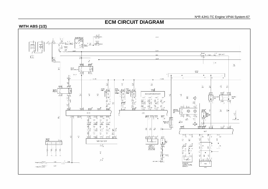
N*R 4JH1-TC Engine VP44 System-67
ECM CIRCUIT DIAGRAMWITH ABS (1/2)

N*R 4JH1-TC Engine VP44 System-68
WITH ABS (2/2)

N*R 4JH1-TC Engine VP44 System-69
WITHOUT ABS (1/2)

N*R 4JH1-TC Engine VP44 System-70
WITHOUT ABS (2/2)

N*R 4JH1-TC Engine VP44 System-71
PARTS LOCATION (LHD)
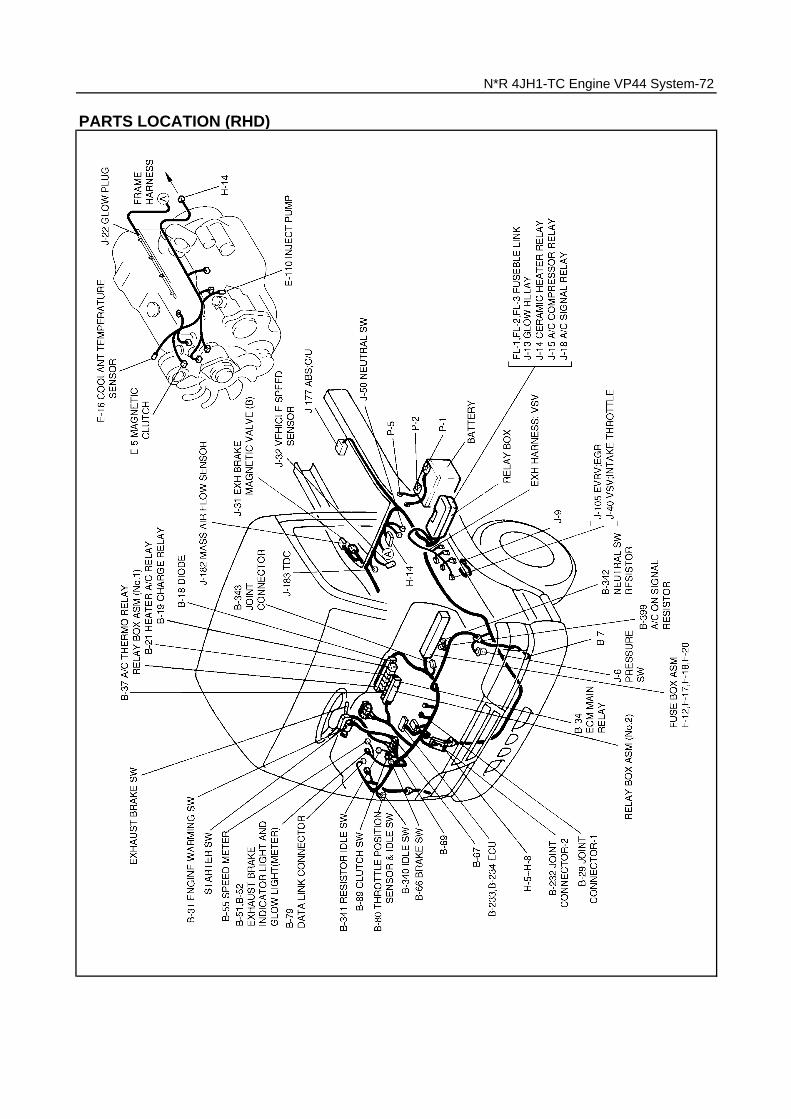
N*R 4JH1-TC Engine VP44 System-72
PARTS LOCATION (RHD)

GROUND LOCATION
RELAY & FUSIBLE LINK LOCATION
RELAY FUSIBLE LINKLHD/RHD LHD/RHD
J-12 RELAY; STARTER 1 80A MAIN
J-13 RELAY; GLOW 2 50A KEY SW
J-14 - 3 60A GLOW
J-15 RELAY; A/C COMP 4 60A (ABS)
J-16 - ( ): IF EQUIPPED
J-17 RELAY; COND. FAN
J-18 RELAY; A/C SIGNAL
J-19 RELAY; RR FOG
J-20 RELAY; MARKER LAMP
N*R 4JH1-TC Engine VP44 System-73

RELAY & FUSE LOCATION
RELAY FUSELHD/RHD LHD/RHD
B-19 RELAY; CHARGE F-1 25A HEATER
B-20 RELAY; HEAD LIGHT F-2 10A A/C
B-21 RELAY; HEATER & A/C F-3 10A STARTER
B-22 RELAY; TAIL F-4 15A CIGAR LIGHTER
B-23 RELAY; DIMMER F-5 10A HEAD LIGHT (RH)
B-24 RELAY; HORN F-6 10A HEAD LIGHT (LH)
B-34 RELAY; ECU F-7 15A POWER DOOR LOCK
B-35 RELAY; CORNERING LIGHT F-8 15A HAZARD, HORN
RELAY; ABS IND. F-9 15A TAIL LIGHT
B-36 RELAY; POWER WINDOW F-10 10A FOG LIGHT
B-37 RELAY; A/C THERMO F-11 15A WIPER, WASHER
B-38 RELAY; FUEL HEATER F-12 10A GAUGE, BACK
F-13 15A (REAR HEATER)
F-14 15A (FUEL HEATER)
F-15 10A (HDLP LEVELING)
F-16 25A POWER WINDOW
F-17 10A STOP LIGHT
F-18 15A GENERATOR
F-19 10A TURN S/LIGHT
F-20 25A ECU
F-21 10A MARKER LIGHT
( ): IF EQUIPPED
N*R 4JH1-TC Engine VP44 System-74

Tech2
Breaker Box
5-8840-0285-0High Impedance Multimeter
5-8840-0385-0Connector Test Adapter Kit
5-8840-0279-0Vacuum Pump With Gauge
N*R 4JH1-TC Engine VP44 System-75
SPECIAL TOOLS

THE RIGHT IS RESERVED TO MAKE CHANGES AT ANY TIME WITHOUT NOTICE.THIS MANUAL MAY NOT BE REPRODUCED OR COPIED, IN WHOLE OR IN PARTWITHOUT THE WRITTEN PERMISSION OF ISUZU MOTORS.
Issued by
ISUZU MOTORS LIMITEDSERVICE MARKETING DEPARTMENT
Tokyo, Japan
COPYRIGHT-ISUZU MOTORS LIMITED
SBT-TM-4JHE-2-03 (version 2)March2003


![]Dmax 2005 3.0 Diesel 4JH1+gestión+electrónica](https://img.pdfslide.tips/doc/110x75/55cf9934550346d0339c2eac/dmax-2005-30-diesel-4jh1gestionelectronica.jpg)