Embed Size (px)
Citation preview
Technical data
Operating instructions
Electric diagrams
Spare parts list
GAS BURNERS
ENBLU 7000.1 PRBLU 8000.1 PRBLU 10000.1 PRBLU 12000.1 PR
Gas train manual is separate
www.eacoon.com
KIT PER 3142589 3143029
www.eacoon.com
EN
4200105118002
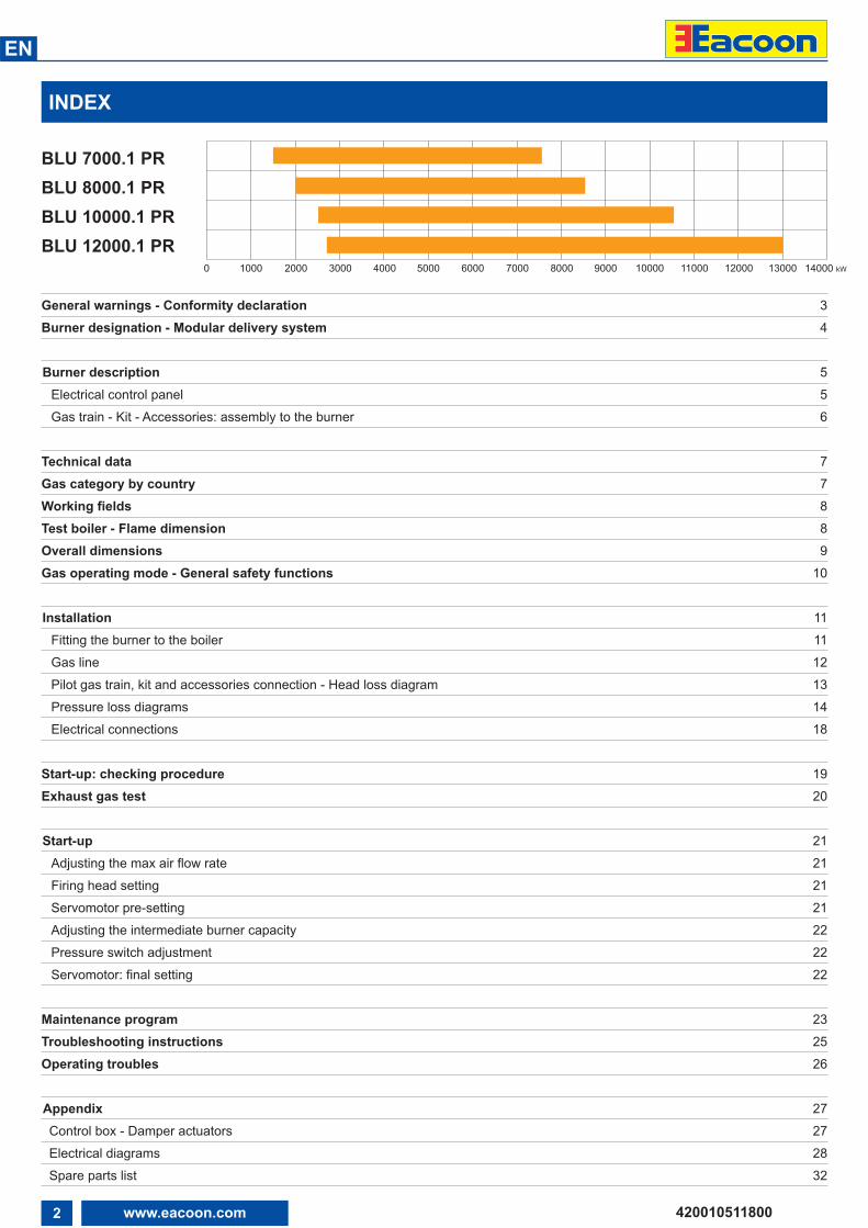
INDEX
BLU 7000.1 PRBLU 8000.1 PRBLU 10000.1 PRBLU 12000.1 PR
0 1000 2000 3000 4000 5000 6000 7000 8000 9000 14000 kW10000 11000 12000 13000
General warnings - Conformity declaration 3Burner designation - Modular delivery system 4
Burner description 5Electrical control panel 5Gas train - Kit - Accessories: assembly to the burner 6
Technical data 7Gas category by country 7Working fields 8Test boiler - Flame dimension 8Overall dimensions 9Gas operating mode - General safety functions 10
Installation 11Fitting the burner to the boiler 11Gas line 12Pilot gas train, kit and accessories connection - Head loss diagram 13Pressure loss diagrams 14Electrical connections 18
Start-up: checking procedure 19Exhaust gas test 20
Start-up 21Adjusting the max air flow rate 21Firing head setting 21Servomotor pre-setting 21Adjusting the intermediate burner capacity 22Pressure switch adjustment 22Servomotor: final setting 22
Maintenance program 23Troubleshooting instructions 25Operating troubles 26
Appendix 27Control box - Damper actuators 27Electrical diagrams 28Spare parts list 32
3www.eacoon.com
EN
420010511800
GENERAL WARNINGS - CONFORMITY DECLARATION
Declaration of conformityfor gas burners
We,Ecoflam Bruciatori S.p.A.
declare under our sole responsibilitythat the products:BLU 7000.1 PRBLU 8000.1 PRBLU 10000.1 PRBLU 12000.1 PR
conform to the following standards:EN 676: 2008EN 60335-1: 2008EN 60335-2-30: 2006EN 60335-2-102: 2007EN 55014-1: 2008 + A1: 2009EN 55014-2: 1998 + A1: 2001 + A2: 2008
These products are built in accordancewith the following directives2006/42/EC Machinery directive2004/108/EC EMC directive2006/95/EC Low voltage directive2009/142/EC Gas appliances Directive
CE certification, when required, must bedone at installation site by the end user
Resana, 20th December 2010M. PANIZZON
BLU burners are designed for thecombustion of natural gas or LPG with kit.The design and function of the burnersmeet the standard EN676. They aresuitable for use with all heat generatorscomplying with standard within theirrespective performance range. Any othertype of application requires the approval ofECOFLAM.Installation, start-up and maintenancemust only be carried out by authorisedspecialists and all applicable guidelinesand regulations must be complied with.
BURNER DESCRIPTIONBLU burners are progressive mechanicalfully automatic monoblock devices.Emissions values may differ, depending oncombustion chamber dimensions,combustion chamber load and the firingsystem (three-pass boilers, boilers withreverse firing).
PACKAGINGThe burner, the gas train and all theadditional components are supplied in amodular system of packages according tothe configuration ordered that based onthe country of installation shall follow theapplicable standards and the local rulesand code of practise. The following standards should beobserved in order to ensure safe,environmentally sound and energy-efficientoperation:
EN 676Forced-draught gas burners
EN 60335-1, -2-102Specification for safety of household andsimilar electrical appliances, particularrequirements for gas burning appliances
GAS LINESWhen installing the gas lines and gas train,the general EN676 directives andguidelines must be observed.EN676 compulsory kit and accessories inorder to comply to the safety regulations. Additional accessories and kits shall beinstalled by the installer in accordance tothe local safety regulations and codes ofpractise.
INSTALLATION LOCATIONThe burner must not be operated in roomscontaining aggressive vapours (e.g. spray,perchloroethylene, hydrocarbontetrachloride, solvent, etc.) or tending toheavy dust formation or high air humidity.Adequate ventilation must be provided atthe place of installation of the furnacesystem to ensure a reliable supply withcombustion air.
!BURNER SELECTION: Type of operation and configuration must be done by professional personnel in order to grant correct working of theburner. Installation, start-up and maintenance must be carried out by authorised specialists and all applicable guidelines and regulations(including local safety regulations and codes of practise) must be observed.
We accept no responsibility for damage arising from:
- inappropriate use;- incorrect installation and/or repair onthe part of the buyer or any third party,including the fitting of non-original parts;- non authorised modifications madeon the burner.
Final delivery and instructions for use
The firing system installer must supplythe operator of the system with operatingand maintenance instructions on or beforefinal delivery. These instructions shouldbe displayed in a prominent location at thepoint of installation of the heat generator,They should include the address andtelephone number of the nearest customerservice centre.
Notes for the operator
The system should be inspected by aspecialist at least once a year.Depending on the type of installation,shorter maintenance intervals may benecessary.It is advisable to take out a maintenancecontract to guarantee regular servicing.
Ecoflam burners have been designed and built in compliance with all current regulationsand directives.All burners comply to the safety and energy saving operation regulations within the standardof their respective performance range. The quality is guaranteed by a quality and managementsystem certified in accordance with ISO 9001:2008.
4 www.eacoon.com
EN
420010511800
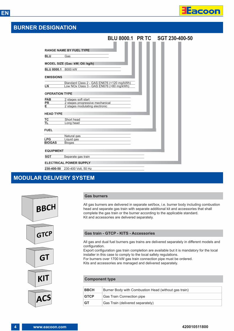
BURNER DESIGNATION
MODULAR DELIVERY SYSTEM
Gas burners
All gas burners are delivered in separate set/box, i.e. burner body including combustionhead and separate gas train with separate additional kit and accessories that shallcomplete the gas train or the burner according to the applicable standard.Kit and accessories are delivered separately.
Gas train - GTCP - KITS - Accessories
All gas and dual fuel burners gas trains are delivered separately in different models andconfiguration.Export configuration gas train completion are available but it is mandatory for the localinstaller in this case to comply to the local safety regulations.For burners over 1700 kW gas train connection pipe must be ordered.Kits and accessories are managed and delivered separately.
Component type
BBCH Burner Body with Combustion Head (without gas train)
GTCP Gas Train Connection pipe
GT Gas Train (delivered separately)
BLU 8000.1 PR TC SGT 230-400-50
BLU Gas
RANGE NAME BY FUEL TYPE
BLU 8000.1 8000 kW
MODEL SIZE (Gas: kW; Oil: kg/h)
Standard Class 2 - GAS EN676 (<120 mg/kWh)LN Low NOx Class 3 - GAS EN676 (<80 mg/kWh)
EMISSIONS
PAB 2 stages soft startPR 2 stages progressive mechanicalE 2 stages modulating electronic
OPERATION TYPE
230-400-50 230-400 Volt, 50 Hz
ELECTRICAL POWER SUPPLY
TC Short headTL Long head
HEAD TYPE
Natural gasLPG Liquid gasBIOGAS Biogas
FUEL
SGT Separate gas train
EQUIPMENT
5www.eacoon.com
EN
420010511800
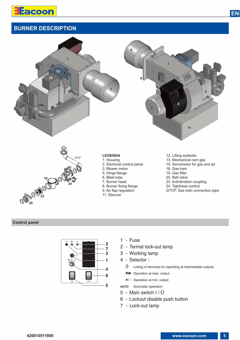
BURNER DESCRIPTION
GTCPLEGENDA1. Housing2. Electrical control panel3. Blower motor5. Hinge flange6. Blast tube7. Burner head8. Burner fixing flange9. Air flap regulation11. Silencer
12. Lifting eyebolts13. Mechanical cam gas15. Servomotor for gas and air16. Gas train19. Gas filter20. Ball valve23. Antivibration coupling24. Tightness controlGTCP. Gas train connection pipe
Control panel
20
23
2419
16
15
13
1
7
6
8
12
1
9
11
32
1 - Fuse2 - Termal lock-out lamp3 - Working lamp4 - Selector : 0 Loking of devoices for operating at intermediate outputs Operation at max. output Operation at min. outputAUTO Automatic operation5 - Main switch I / O6 - Lockout disable push button7 - Lock-out lamp
PGM EXIT
5
0I
GAS
RESET
0
AUTO
641
73
2
6 www.eacoon.com
EN
420010511800
MAir
Gas
313
160170
144
142141
120
150
314
349
151
155
100
143
To be supplied by the installer
To be supplied by the installer
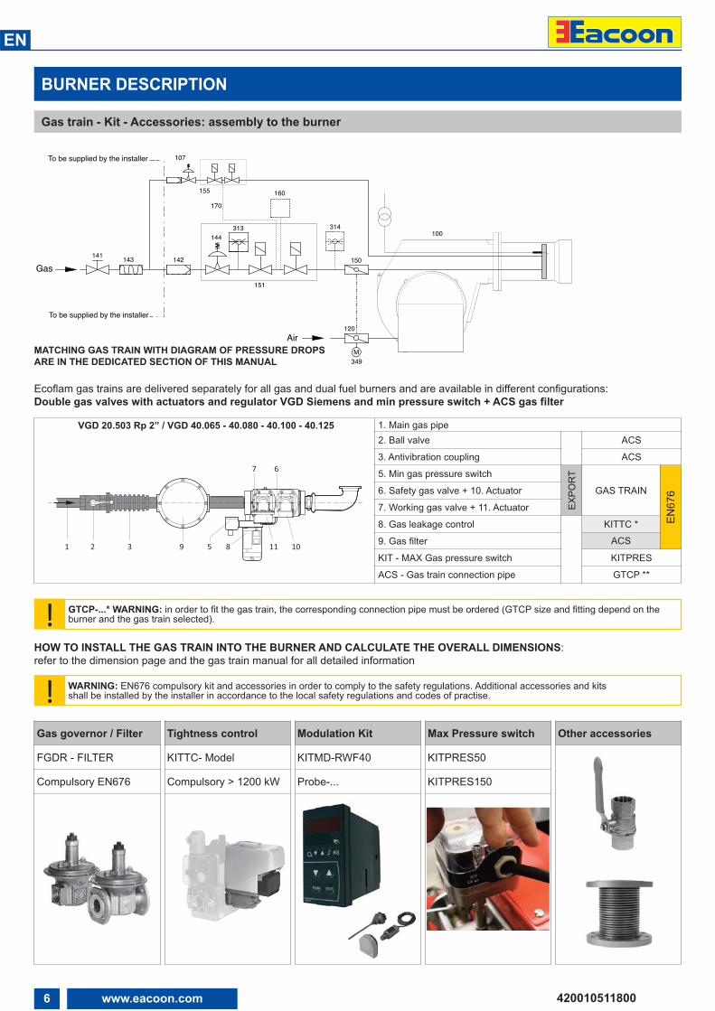
107143 Antivibration coupling144 Gas governor150 Batterfly valve151 Gas train Landis VGD.... 155 Pilot gas train160 Kit tightness control (optional)170 Kit tightness control for pilot gas valve (optional)313 Min.gas pressure switch 314 Max.gas pressure switch (optional)349 Air/gas damper motor
BURNER DESCRIPTION
Gas train - Kit - Accessories: assembly to the burner
MATCHING GAS TRAIN WITH DIAGRAM OF PRESSURE DROPSARE IN THE DEDICATED SECTION OF THIS MANUAL
VGD 20.503 Rp 2” / VGD 40.065 - 40.080 - 40.100 - 40.125 1. Main gas pipe2. Ball valve ACS
3. Antivibration coupling ACS
5. Min gas pressure switch
EXPO
RT
GAS TRAIN
EN67
66. Safety gas valve + 10. Actuator
7. Working gas valve + 11. Actuator
8. Gas leakage control KITTC *
9. Gas filter ACS
KIT - MAX Gas pressure switch KITPRES
ACS - Gas train connection pipe GTCP **
! GTCP-...* WARNING: in order to fit the gas train, the corresponding connection pipe must be ordered (GTCP size and fitting depend on theburner and the gas train selected).
! WARNING: EN676 compulsory kit and accessories in order to comply to the safety regulations. Additional accessories and kitsshall be installed by the installer in accordance to the local safety regulations and codes of practise.
HOW TO INSTALL THE GAS TRAIN INTO THE BURNER AND CALCULATE THE OVERALL DIMENSIONS:refer to the dimension page and the gas train manual for all detailed information
Gas governor / Filter
FGDR - FILTER
Compulsory EN676
Tightness control
KITTC- Model
Compulsory > 1200 kW
Modulation Kit
KITMD-RWF40
Probe-...
Max Pressure switch
KITPRES50
KITPRES150
Other accessories
Ecoflam gas trains are delivered separately for all gas and dual fuel burners and are available in different configurations:Double gas valves with actuators and regulator VGD Siemens and min pressure switch + ACS gas filter
1 2 3 9 118 105
67
7www.eacoon.com
EN
420010511800
TECHNICAL DATA
GAS CATEGORY BY COUNTRY
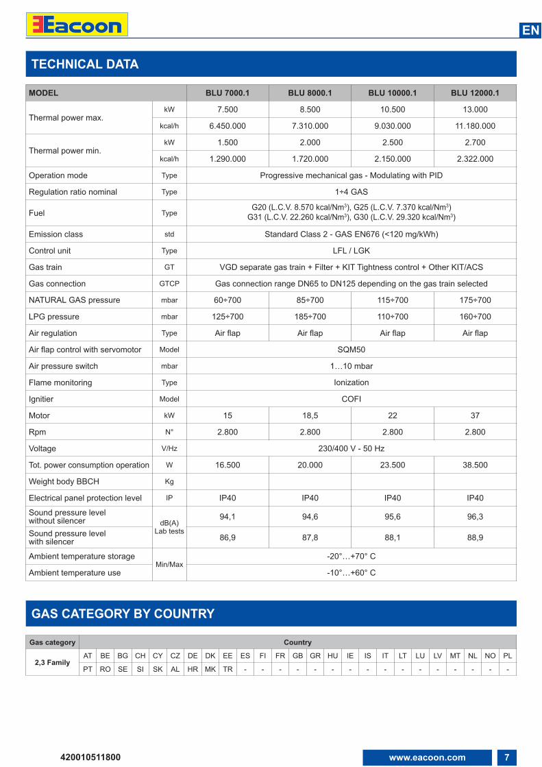
MODEL BLU 7000.1 BLU 8000.1 BLU 10000.1 BLU 12000.1
Thermal power max.kW 7.500 8.500 10.500 13.000
kcal/h 6.450.000 7.310.000 9.030.000 11.180.000
Thermal power min.kW 1.500 2.000 2.500 2.700
kcal/h 1.290.000 1.720.000 2.150.000 2.322.000
Operation mode Type Progressive mechanical gas - Modulating with PID
Regulation ratio nominal Type 1÷4 GAS
Fuel TypeG20 (L.C.V. 8.570 kcal/Nm3), G25 (L.C.V. 7.370 kcal/Nm3)
G31 (L.C.V. 22.260 kcal/Nm3), G30 (L.C.V. 29.320 kcal/Nm3)
Emission class std Standard Class 2 - GAS EN676 (<120 mg/kWh)
Control unit Type LFL / LGK
Gas train GT VGD separate gas train + Filter + KIT Tightness control + Other KIT/ACS
Gas connection GTCP Gas connection range DN65 to DN125 depending on the gas train selected
NATURAL GAS pressure mbar 60÷700 85÷700 115÷700 175÷700
LPG pressure mbar 125÷700 185÷700 110÷700 160÷700
Air regulation Type Air flap Air flap Air flap Air flap
Air flap control with servomotor Model SQM50
Air pressure switch mbar 1…10 mbar
Flame monitoring Type Ionization
Ignitier Model COFI
Motor kW 15 18,5 22 37
Rpm N° 2.800 2.800 2.800 2.800
Voltage V/Hz 230/400 V - 50 Hz
Tot. power consumption operation W 16.500 20.000 23.500 38.500
Weight body BBCH Kg
Electrical panel protection level IP IP40 IP40 IP40 IP40
Sound pressure level without silencer dB(A)
Lab tests
94,1 94,6 95,6 96,3
Sound pressure level with silencer 86,9 87,8 88,1 88,9
Ambient temperature storageMin/Max
-20°…+70° C
Ambient temperature use -10°…+60° C
Gas category Country
2,3 FamilyAT BE BG CH CY CZ DE DK EE ES FI FR GB GR HU IE IS IT LT LU LV MT NL NO PL
PT RO SE SI SK AL HR MK TR - - - - - - - - - - - - - - - -
8 www.eacoon.com
EN
420010511800
WORKING FIELDS
TEST BOILER - FLAME DIMENSIONS
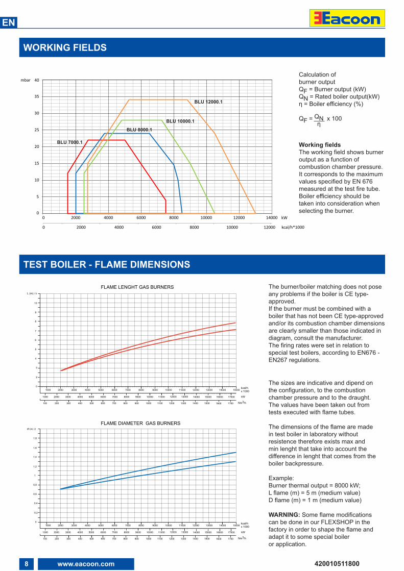
The burner/boiler matching does not poseany problems if the boiler is CE type-approved.If the burner must be combined with aboiler that has not been CE type-approvedand/or its combustion chamber dimensionsare clearly smaller than those indicated indiagram, consult the manufacturer.The firing rates were set in relation tospecial test boilers, according to EN676 -EN267 regulations.
The sizes are indicative and dipend onthe configuration, to the combustionchamber pressure and to the draught.The values have been taken out fromtests executed with flame tubes.
The dimensions of the flame are madein test boiler in laboratory withoutresistence therefore exists max andmin lenght that take into account thedifference in lenght that comes from theboiler backpressure.
Example:Burner thermal output = 8000 kW;L flame (m) = 5 m (medium value)D flame (m) = 1 m (medium value)
WARNING: Some flame modificationscan be done in our FLEXSHOP in thefactory in order to shape the flame andadapt it to some special boileror application.
L (m)
2000 3000 4000 5000 6000 7000 8000 9000 10000
4
5
1000
2000 30001000
6
11000
0
2
3
7
8
12000 kW13000
9
10
11
Nm3/h100 200 300 400 500
kcal/hx 10004000 5000 6000 7000 8000 9000 10000 11000 12000 13000 14000 15000
14000 15000 16000 17000
Ø (m)
2000 3000 4000 5000 6000 7000 8000 9000 10000
0,6
0,8
1000
2000 30001000
1
11000
0
0,2
0,4
1,2
1,4
12000 kW13000
1,6
1,8
2
kcal/hx 10004000 5000 6000 7000 8000 9000 10000 11000 12000 13000 14000 15000
14000 15000 16000 17000
FLAME LENGHT GAS BURNERS
FLAME DIAMETER GAS BURNERS
600 700 800 900 1000 1100 1200 1300 1400 1500 1600 1700
Nm3/h100 200 300 400 500 600 700 800 900 1000 1100 1200 1300 1400 1500 1600 1700
0
5
10
15
20
25
30
35
40
0 2000 4000 6000 8000 10000 12000 14000
0 2000 4000
kW
kcal/h*10006000 8000 10000 12000
mbar
BLU 7000.1
BLU 12000.1
BLU 10000.1
BLU 8000.1
Working fieldsThe working field shows burneroutput as a function ofcombustion chamber pressure. It corresponds to the maximumvalues specified by EN 676measured at the test fire tube.Boiler efficiency should betaken into consideration whenselecting the burner.
Calculation of burner outputQF = Burner output (kW)QN = Rated boiler output(kW)η = Boiler efficiency (%)
QF = QN x 100η
9www.eacoon.com
EN
420010511800
E D - D1
F
G
CBA
H1
M16
550
M
L
I
N
O
600
540
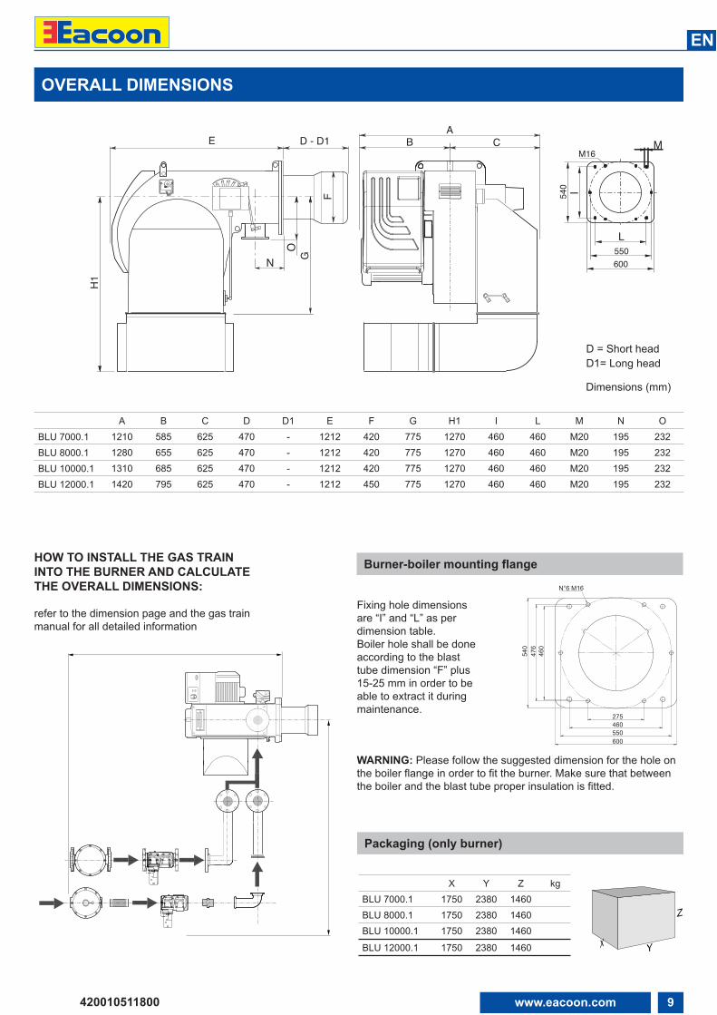
OVERALL DIMENSIONS
HOW TO INSTALL THE GAS TRAININTO THE BURNER AND CALCULATETHE OVERALL DIMENSIONS:
refer to the dimension page and the gas trainmanual for all detailed information
Fixing hole dimensionsare “I” and “L” as perdimension table.Boiler hole shall be doneaccording to the blasttube dimension “F” plus15-25 mm in order to beable to extract it duringmaintenance.
Burner-boiler mounting flange
Packaging (only burner)
WARNING: Please follow the suggested dimension for the hole onthe boiler flange in order to fit the burner. Make sure that betweenthe boiler and the blast tube proper insulation is fitted.
X Y Z kgBLU 7000.1 1750 2380 1460BLU 8000.1 1750 2380 1460BLU 10000.1 1750 2380 1460
BLU 12000.1 1750 2380 1460
Dimensions (mm)
D = Short headD1= Long head
X Y
Z
A B C D D1 E F G H1 I L M N OBLU 7000.1 1210 585 625 470 - 1212 420 775 1270 460 460 M20 195 232BLU 8000.1 1280 655 625 470 - 1212 420 775 1270 460 460 M20 195 232BLU 10000.1 1310 685 625 470 - 1212 420 775 1270 460 460 M20 195 232BLU 12000.1 1420 795 625 470 - 1212 450 775 1270 460 460 M20 195 232
460
540
460
600550
476
275
N° 6 M16
10 www.eacoon.com
EN
420010511800
GAS OPERATING MODE - GENERAL SAFETY FUNCTIONS
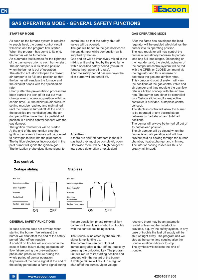
START-UP MODE
As soon as the furnace system is requiredto supply heat, the burner control circuitwill close and the program flow started.When the program has come to its end,the burner will be turned on.An automatic test is made for the tightnessof the gas valves prior to each burner start.The air damper is in its closed positionwhen the burner is out of operation.The electric actuator will open the closedair damper to its full-load position so thatthe burner will ventilate the furnace andthe exhaust hoods with the specified airrate. Shortly after the preventilation process hasbeen started the lack-of-air cut-out mustchange over to operating position within acertain time, i.e. the minimum air pressuresetting must be reached and maintaineduntil the burner is turned off. At the end ofthe specified pre-ventilation time the airdamper will be moved into its partial-loadposition in a linked control concept with thegas damper.The ignition transformer will be started.At the end of the pre-ignition time theignition gas solenoid valves will be openedto allow gas to flow into the pilot burner.The ignition electrodes incorporated in thepilot burner will ignite the ignition gas.The ionization probe gives flame signal to
control box so that the safety shut-offvalves will be opened.The gas will be fed to the gas nozzles viathe gas damper while combustion air issupplied by the fan. Gas and air will be intensively mixed in themixing unit and ignited by the pilot flamewith a specified safety period (minimumfurnace heat generating rate).After the safety period has run down thepilot burner will be turned off.
Attention:If there are shut-off dampers in the fluegas tract they must be completely open.Otherwise there will be a high danger oflow-speed detonation or explosion!
GAS OPERATING MODE
After the flame has developed the loadregulator will be enabled which brings theburner into its operating position.The load regulator will now control theburner automatically between its partial-load and full-load stages. Depending onthe heat demand, the electric actuator ofthe compound control system will be fedwith the OPEN or CLOSE command viathe regulator and thus increase ordecrease the gas and air flow rates.This compound control system will varythe positions of the gas control valve andair damper and thus regulate the gas flowrate in a linked concept with the air flowrate. The burner can either be controlledby a 2-stage sliding or, if a respectivecontroller is provided, a stepless controlconcept. The stepless control will allow the burnerto be operated at any desired stagebetween its partial-load and full-loadpositions. The burner will always be turned off out ofits partial-load position. The air damper will be closed when theburner is out of operation and will thusprevent cold air flowing through the burnerchamber, heat exchanger and chimney.The interior cooling losses will thus begreatly minimized.
GENERAL SAFETY FUNCTIONS
In case a flame does not develop whenstarting the burner (fuel release) theburner will shut off at the end of the safetyperiod (shut-off on trouble). A shut-off on trouble will also occur in thecase of flame failure during operation, airflow failure during the pre-ventilationphase and pressure failure during thewhole period of burner operation. Any failure of the flame signal at the end ofthe safety period and a flame signal during
the pre-ventilation phase (external lightcontrol) will result in a shut-off on troublewith the control box being locked.
The trouble is indicated by the troublesignal lamp lighting up. The control box can be unlockedimmediately after a shut-off on trouble bypressing the unlocking key. The programunit will return to its starting position andproceed with the restart of the burner.A voltage failure will result in a regularshut-off of the burner. Upon voltage
recovery there may be an automaticrestart unless another interlock isprovided, e.g. by the safety system. In anycase of trouble the fuel oil supply will beshut off right away. The program unit willstop at the same time causing also thetrouble location indicator to stop.The symbols will indicate the kind oftrouble.
Leistungsregulierung
ZündungGasventile
EIN
Teillast
Freigabe
AUS
Betriebsstellung
Vollast
Leistungsregulierung
EIN
GasventileZündung
StartlastTeillast
Freigabe
AUS
Betriebsstellung
Vollast
2-stage sliding Stepless
Gas control:
ON OFF
Full load
Operating position
Load regulator
Release
Partial load
Ignition / gas valves
Full load
Operating position
Load regulator
Release
Start loadPartial load
Ignition / gas valves
ON OFF
11www.eacoon.com
EN
420010511800
! WARNING: handling and moving operations must be carried out by specialised personnel.Use the eyebolts to lift the burner in order that it will not overturn and fall down.
INSTALLATION
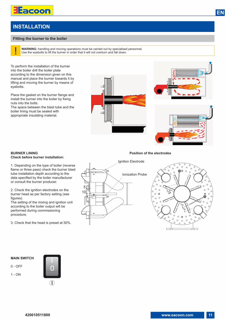
Fitting the burner to the boiler
To perform the installation of the burnerinto the boiler drill the boiler plateaccording to the dimension given on thismanual and place the burner towards it bylifting and moving the burner by means ofeyebolts.
Place the gasket on the burner flange andinstall the burner into the boiler by fixingnuts into the bolts.The space between the blast tube and theboiler lining must be sealed withappropriate insulating material.
BURNER LININGCheck before burner installation:
1. Depending on the type of boiler (reverseflame or three pass) check the burner blasttube installation depth according to thedata specified by the boiler manufactureror consult the burner producer.
2. Check the ignition electrodes on theburner head as per factory setting (seefigures).The setting of the mixing and ignition unitaccording to the boiler output will beperformed during commissioningprocedure.
3. Check that the head is preset at 50%.
Position of the electrodes
0IMAIN SWITCH
0 - OFF
1 - ON
510
Elettrodoaccensione
Elettrodorivelazione
Ignition Electrode
Ionization Probe
==
15

12 www.eacoon.com
EN
420010511800
MAir
Gas
313
160170
144
142141
120
150
314
349
151
155
100
143
To be supplied by the installer
To be supplied by the installer
107
100 Burner107 Pilot gas filter/governor120 Air damper141 Ball valve142 Gas filter143 Antivibration coupling144 Gas governor150 Batterfly valve151 Gas train Landis VGD.... 155 Pilot gas train160 Kit tightness control (optional)170 Kit tightness control for pilot gas valve (optional)313 Min.gas pressure switch 314 Max.gas pressure switch (optional)349 Air/gas damper motor
INSTALLATION
Gas line
GAS VALVES AND INSTRUMENTS GROUPThe gas valves and instruments group usedwith the furnace will be selected according tothe specific requirements to be met by aburner system.The following factors must be taken intoaccount:• burner output• furnace back pressure• gas pressure loss of the burner head• gas pressure losses of the gas valves andinstruments group
NOTE: Only gas trains assembled by the burner manufacturer and approved inaccordance with the burner test specifications.EN676 compulsory kit and accessories in order to comply to the safety regulations. Additional accessories and kits shall be installed by the installer in accordance to thelocal safety regulations and codes of practise.
GAS CONNECTION PRESSUREA minimum connection pressure must beavailable upstream of the burner gas valveto ensure the proper functioning of theburner.WARNING: the total gas pressure lossmust always be smaller than the availablegas flow pressure.For the installation of the valves andinstruments group take care to observe themounting instructions supplied by theirmanufacturers (these are packed with theequipment).The gas line installed to the burner mustbe dimensioned in accordance with thethroughput rate and the availablepressure.For selecting the nominal bore “DN” of thegas valves and instruments group careshould be taken to observe the flueresistance of the boiler and the gaspressure loss of the burner and valves andinstruments group.
GAS VALVES AND INSTRUMENTS GROUPThe gas valves and instruments group canbe connected directly to the gas feed line.
Take care to observe the correct order ofinstallation and direction of flow (arrow onhousing).Check the valves and instruments andconnection pieces for absence of dirtparticles and foreign matter beforeinstallation and initial operation. To provideeffective conditions for start-up make surethe distance between the burner and thegas stop valve is as short as possible.
LEAK TESTThe gas line upstream of the burner gasvalves and instruments group must beinstalled in accordance with the applicableregulations, checked for absence of leaks,vented and certified accordingly by the gasinstallation company. The screwed unionsand flanged joints must be checked forproper tightness (by making a pressuretest). The leak test must be made underpressure using approved foaming agentswhich do not cause corrosion. For steamboiler furnaces the result of the leak testmust be duly certified.
VENTINGPrior to taking the burner into operation orafter any repair work make sure to vent thecomplete gas feed line and the gas valvesand instruments group into the openatmosphere (e.g. by means of a hose)taking care to avoid any hazards.In no case should the gas line be ventedinto the heating or furnace chambers.Make use of a test burner to check the gas-carrying spaces are free from aninflammable gas mixture.
SUPPORTThe valves and instruments group must besupported with a telescopic jackingmember or similar during and afterinstallation (e.g. on filter and valve).
JOINTIt is recommended to provide an easy todisconnect joint (with planar sealing faces)to facilitate repair work on the boiler(furnace) and allow the boiler door to beswivelled out if required.
CONNECTION DIAGRAM FOR BURNERS WITH SEPARATE PILOT (GAS TRAIN LANDIS VGD...)
13www.eacoon.com
EN
420010511800
INSTALLATION
Pilot gas train, kit and accessories connection - head loss diagram
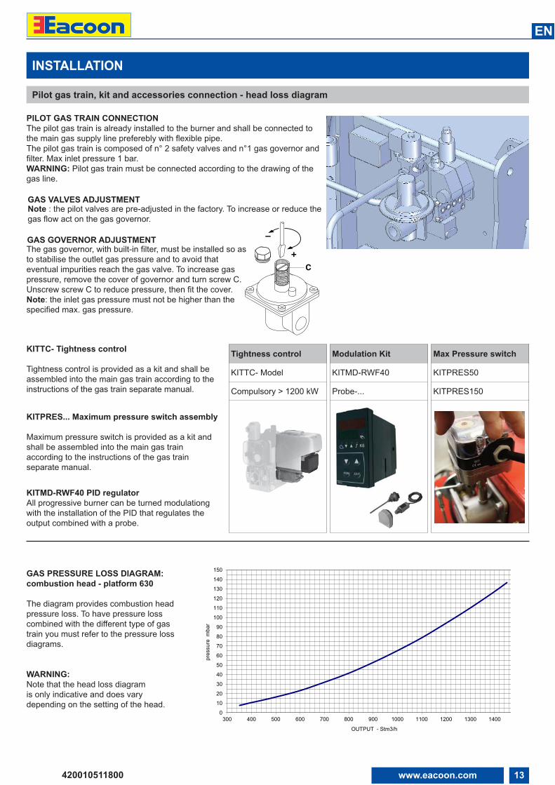
GAS PRESSURE LOSS DIAGRAM:combustion head - platform 630
The diagram provides combustion headpressure loss. To have pressure losscombined with the different type of gastrain you must refer to the pressure lossdiagrams.
WARNING:Note that the head loss diagramis only indicative and does varydepending on the setting of the head.
0
10
20
30
40
5060
70
80
90
100
110
120
130
140
150
300 400 500 600 700 800 900 1000 1100 1200 1300 1400
pres
sure
mba
r
OUTPUT - Stm3/h
PILOT GAS TRAIN CONNECTIONThe pilot gas train is already installed to the burner and shall be connected tothe main gas supply line preferebly with flexible pipe.The pilot gas train is composed of n° 2 safety valves and n°1 gas governor andfilter. Max inlet pressure 1 bar.WARNING: Pilot gas train must be connected according to the drawing of thegas line.
GAS VALVES ADJUSTMENTNote : the pilot valves are pre-adjusted in the factory. To increase or reduce thegas flow act on the gas governor.
GAS GOVERNOR ADJUSTMENTThe gas governor, with built-in filter, must be installed so asto stabilise the outlet gas pressure and to avoid thateventual impurities reach the gas valve. To increase gaspressure, remove the cover of governor and turn screw C.Unscrew screw C to reduce pressure, then fit the cover. Note: the inlet gas pressure must not be higher than thespecified max. gas pressure.
KITTC- Tightness control
Tightness control is provided as a kit and shall beassembled into the main gas train according to theinstructions of the gas train separate manual.
KITPRES... Maximum pressure switch assembly
Maximum pressure switch is provided as a kit andshall be assembled into the main gas trainaccording to the instructions of the gas trainseparate manual.
KITMD-RWF40 PID regulatorAll progressive burner can be turned modulationgwith the installation of the PID that regulates theoutput combined with a probe.
Tightness control
KITTC- Model
Compulsory > 1200 kW
Modulation Kit
KITMD-RWF40
Probe-...
Max Pressure switch
KITPRES50
KITPRES150
+
–
C
14 www.eacoon.com
EN
420010511800
INSTALLATION
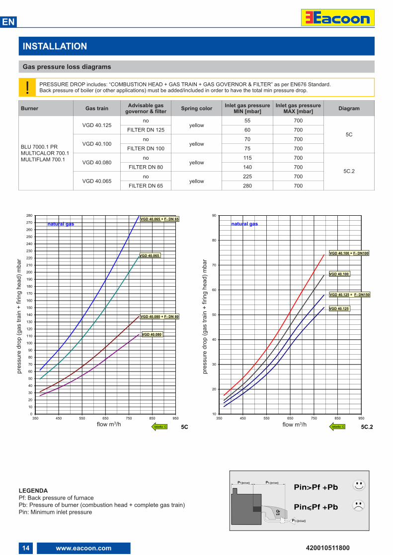
Gas pressure loss diagrams
! PRESSURE DROP includes: “COMBUSTION HEAD + GAS TRAIN + GAS GOVERNOR & FILTER” as per EN676 Standard.Back pressure of boiler (or other applications) must be added/included in order to have the total min pressure drop.
LEGENDAPf: Back pressure of furnacePb: Pressure of burner (combustion head + complete gas train)Pin: Minimum inlet pressure
Burner Gas train Advisable gasgovernor & filter Spring color Inlet gas pressure
MIN [mbar]Inlet gas pressure
MAX [mbar] Diagram
BLU 7000.1 PRMULTICALOR 700.1MULTIFLAM 700.1
VGD 40.125no
yellow55 700
5CFILTER DN 125 60 700
VGD 40.100no
yellow70 700
FILTER DN 100 75 700
VGD 40.080no
yellow115 700
5C.2FILTER DN 80 140 700
VGD 40.065no
yellow225 700
FILTER DN 65 280 700
0
10
20
30
40
50
60
70
80
90
100
110
120
130
140
150
160
170
180
190
200
210
220
230
240
250
260
270
280
350 450 550 650 750 850 950
perd
ite d
i car
ico
(ram
pa g
as +
test
a di
com
bust
ione
/ pr
essu
re d
rop
(gas
trai
n +
firin
g he
ad) m
bar
portata/flow m3/h 5C
VGD 40.080 + F- DN 80
VGD 40.065 + F- DN 65natural gas
VGD 40.065
VGD 40.080
tabella C
10
20
30
40
50
60
70
80
90
350 450 550 650 750 850 950
perd
ite d
i car
ico
(ram
pa g
as +
test
a di
com
bust
ione
/ pr
essu
re d
rop
(gas
trai
n +
firin
g he
ad) m
bar
portata/flow m3/h 5C.2
VGD 40.100 + F- DN100
VGD 40.125 + F- DN150
natural gas
VGD 40.125
VGD 40.100
tabella Cflow m3/h
pres
sure
dro
p (g
as tr
ain
+ fir
ing
head
) mba
r
flow m3/h
pres
sure
dro
p (g
as tr
ain
+ fir
ing
head
) mba
r
15www.eacoon.com
EN
420010511800
INSTALLATION
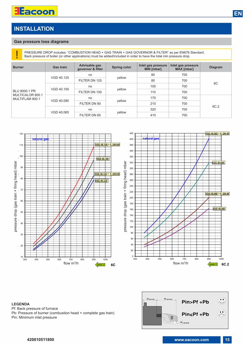
Gas pressure loss diagrams
! PRESSURE DROP includes: “COMBUSTION HEAD + GAS TRAIN + GAS GOVERNOR & FILTER” as per EN676 Standard.Back pressure of boiler (or other applications) must be added/included in order to have the total min pressure drop.
LEGENDAPf: Back pressure of furnacePb: Pressure of burner (combustion head + complete gas train)Pin: Minimum inlet pressure
Burner Gas train Advisable gasgovernor & filter Spring color Inlet gas pressure
MIN [mbar]Inlet gas pressure
MAX [mbar] Diagram
BLU 8000.1 PRMULTICALOR 800.1MULTIFLAM 800.1
VGD 40.125no
yellow80 700
6CFILTER DN 125 85 700
VGD 40.100no
yellow100 700
FILTER DN 100 110 700
VGD 40.080no
yellow170 700
6C.2FILTER DN 80 210 700
VGD 40.065no
yellow320 700
FILTER DN 65 410 700
10
20
30
40
50
60
70
80
90
100
110
120
350 450 550 650 750 850 950 1050
perd
ite d
i car
ico
(ram
pa g
as +
test
a di
com
bust
ione
/ pr
essu
re d
rop
(gas
trai
n +
firin
g he
ad) m
bar
portata/flow m3/h 6C
VGD 40.100 + F- DN100
VGD 40.125 + F- DN150
natural gas
VGD 40.125
VGD 40.100
tabella C
0
20
40
60
80
100
120
140
160
180
200
220
240
260
280
300
320
340
360
380
400
420
350 450 550 650 750 850 950 1050
perd
ite d
i car
ico
(ram
pa g
as +
test
a di
com
bust
ione
/ pr
essu
re d
rop
(gas
trai
n +
firin
g he
ad) m
bar
portata/flow m3/h 6C.2
VGD 40.080 + F- DN 80
VGD 40.065 + F- DN 65
natural gas
VGD 40.065
VGD 40.080
tabella Cflow m3/h
pres
sure
dro
p (g
as tr
ain
+ fir
ing
head
) mba
r
flow m3/h
pres
sure
dro
p (g
as tr
ain
+ fir
ing
head
) mba
r
16 www.eacoon.com
EN
420010511800
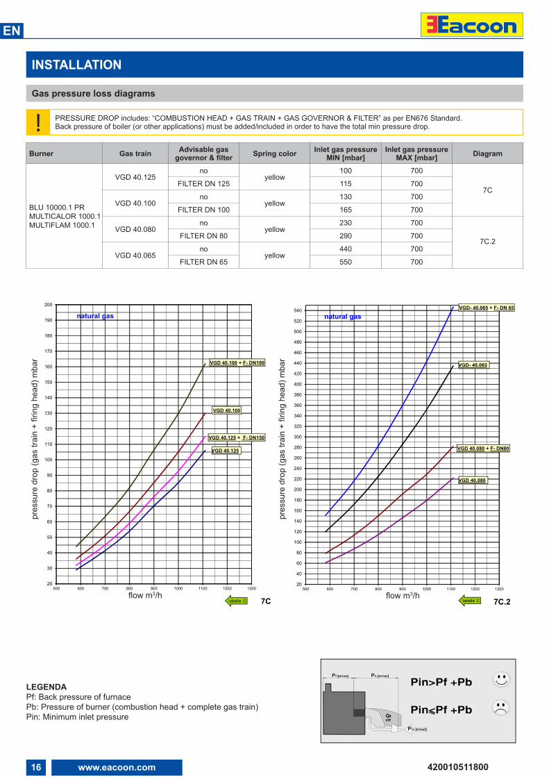
INSTALLATION
Gas pressure loss diagrams
! PRESSURE DROP includes: “COMBUSTION HEAD + GAS TRAIN + GAS GOVERNOR & FILTER” as per EN676 Standard.Back pressure of boiler (or other applications) must be added/included in order to have the total min pressure drop.
LEGENDAPf: Back pressure of furnacePb: Pressure of burner (combustion head + complete gas train)Pin: Minimum inlet pressure
Burner Gas train Advisable gasgovernor & filter Spring color Inlet gas pressure
MIN [mbar]Inlet gas pressure
MAX [mbar] Diagram
BLU 10000.1 PRMULTICALOR 1000.1MULTIFLAM 1000.1
VGD 40.125no
yellow100 700
7CFILTER DN 125 115 700
VGD 40.100no
yellow130 700
FILTER DN 100 165 700
VGD 40.080no
yellow230 700
7C.2FILTER DN 80 290 700
VGD 40.065no
yellow440 700
FILTER DN 65 550 700
20
30
40
50
60
70
80
90
100
110
120
130
140
150
160
170
180
190
200
500 600 700 800 900 1000 1100 1200 1300
perd
ite d
i car
ico
(ram
pa g
as +
test
a di
com
bust
ione
/ pr
essu
re d
rop
(gas
trai
n +
firin
g he
ad) m
bar
portata/flow m3/h 7C
VGD 40.100 + F- DN100
VGD 40.125 + F- DN150
natural gas
VGD 40.125
VGD 40.100
tabella C
20
40
60
80
100
120
140
160
180
200
220
240
260
280
300
320
340
360
380
400
420
440
460
480
500
520
540
500 600 700 800 900 1000 1100 1200 1300
perd
ite d
i car
ico
(ram
pa g
as +
test
a di
com
bust
ione
/ pr
essu
re d
rop
(gas
trai
n +
firin
g he
ad) m
bar
portata/flow m3/h 7C.2
VGD 40.080 + F- DN80
VGD- 40.065 + F- DN 65
natural gas
VGD 40.080
VGD- 40.065
tabella Cflow m3/h
pres
sure
dro
p (g
as tr
ain
+ fir
ing
head
) mba
r
pres
sure
dro
p (g
as tr
ain
+ fir
ing
head
) mba
r
flow m3/h
17www.eacoon.com
EN
420010511800
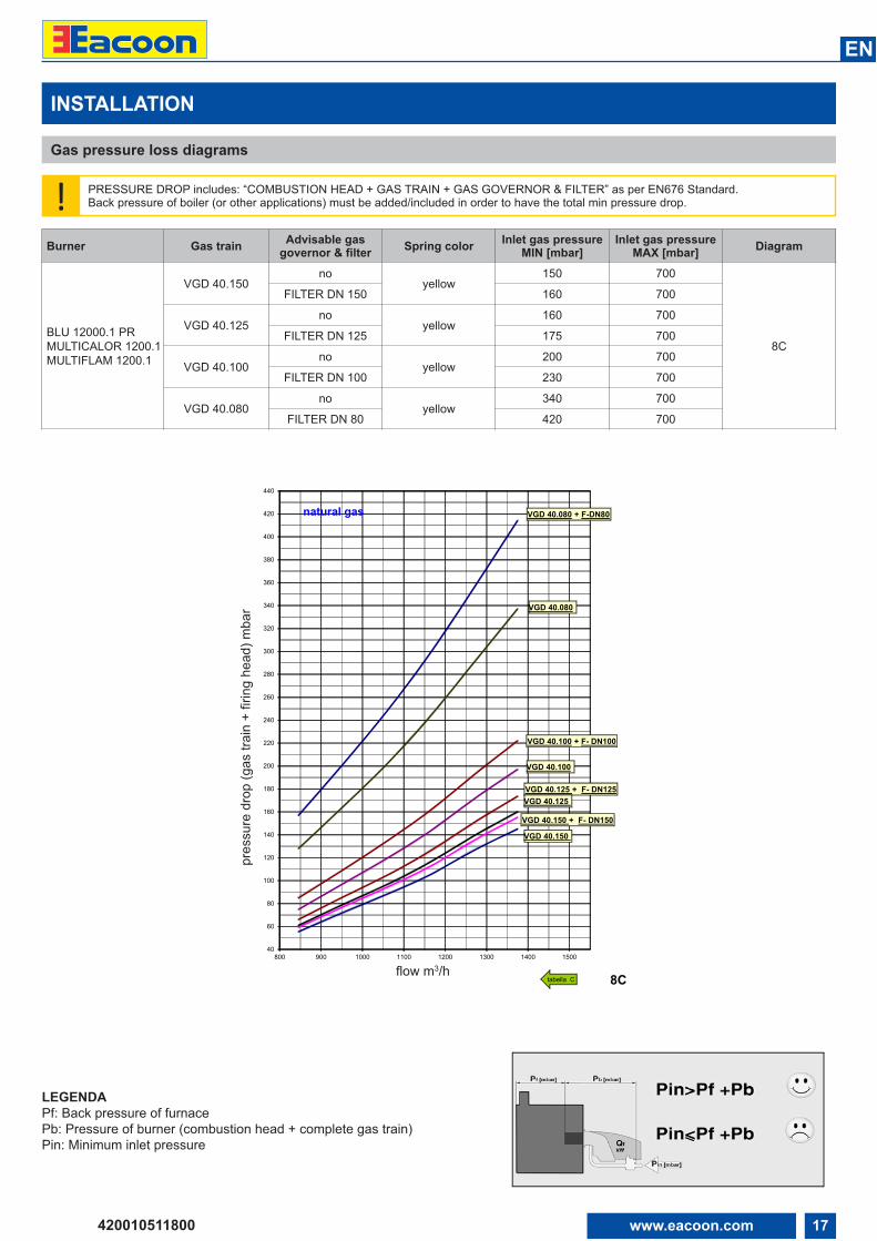
INSTALLATION
Gas pressure loss diagrams
! PRESSURE DROP includes: “COMBUSTION HEAD + GAS TRAIN + GAS GOVERNOR & FILTER” as per EN676 Standard.Back pressure of boiler (or other applications) must be added/included in order to have the total min pressure drop.
LEGENDAPf: Back pressure of furnacePb: Pressure of burner (combustion head + complete gas train)Pin: Minimum inlet pressure
Burner Gas train Advisable gasgovernor & filter Spring color Inlet gas pressure
MIN [mbar]Inlet gas pressure
MAX [mbar] Diagram
BLU 12000.1 PRMULTICALOR 1200.1MULTIFLAM 1200.1
VGD 40.150no
yellow150 700
8C
FILTER DN 150 160 700
VGD 40.125no
yellow160 700
FILTER DN 125 175 700
VGD 40.100no
yellow200 700
FILTER DN 100 230 700
VGD 40.080no
yellow340 700
FILTER DN 80 420 700
40
60
80
100
120
140
160
180
200
220
240
260
280
300
320
340
360
380
400
420
440
800 900 1000 1100 1200 1300 1400 1500
perd
ite d
i car
ico
(ram
pa g
as +
test
a di
com
bust
ione
/ pr
essu
re d
rop
(gas
trai
n +
firin
g he
ad) m
bar
portata/flow m3/h8C
VGD 40.080 + F-DN80
VGD 40.100 + F- DN100
VGD 40.125 + F- DN125
natural gas
VGD 40.125
VGD 40.100
VGD 40.080
tabella C
VGD 40.150 + F- DN150
VGD 40.150
flow m3/h
pres
sure
dro
p (g
as tr
ain
+ fir
ing
head
) mba
r
18 www.eacoon.com
EN
420010511800
INSTALLATION
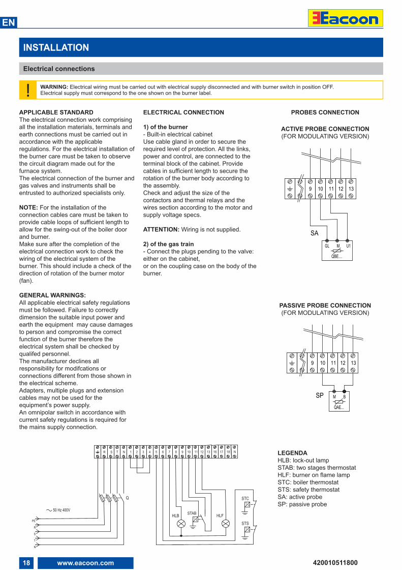
Electrical connections
! WARNING: Electrical wiring must be carried out with electrical supply disconnected and with burner switch in position OFF.Electrical supply must correspond to the one shown on the burner label.
APPLICABLE STANDARDThe electrical connection work comprisingall the installation materials, terminals andearth connections must be carried out inaccordance with the applicableregulations. For the electrical installation ofthe burner care must be taken to observethe circuit diagram made out for thefurnace system.The electrical connection of the burner andgas valves and instruments shall beentrusted to authorized specialists only.
NOTE: For the installation of theconnection cables care must be taken toprovide cable loops of sufficient length toallow for the swing-out of the boiler doorand burner. Make sure after the completion of theelectrical connection work to check thewiring of the electrical system of theburner. This should include a check of thedirection of rotation of the burner motor(fan).
GENERAL WARNINGS:All applicable electrical safety regulationsmust be followed. Failure to correctlydimension the suitable input power andearth the equipment may cause damagesto person and compromise the correctfunction of the burner therefore theelectrical system shall be checked byqualifed personnel. The manufacturer declines allresponsibility for modifcations orconnections different from those shown inthe electrical scheme.Adapters, multiple plugs and extensioncables may not be used for theequipment’s power supply. An omnipolar switch in accordance withcurrent safety regulations is required forthe mains supply connection.
ELECTRICAL CONNECTION
1) of the burner- Built-in electrical cabinetUse cable gland in order to secure therequired level of protection. All the links,power and control, are connected to theterminal block of the cabinet. Providecables in sufficient length to secure therotation of the burner body according tothe assembly.Check and adjust the size of thecontactors and thermal relays and thewires section according to the motor andsupply voltage specs.
ATTENTION: Wiring is not supplied.
2) of the gas train- Connect the plugs pending to the valve:either on the cabinet,or on the coupling case on the body of theburner.
PROBES CONNECTION
12 13119 10
9 13121110
SA
QBE....
GL M U1
SPQAE...
M B
ACTIVE PROBE LINK
PASSIVE PROBE LINK
T P
1 2 N1716 18
STAB HLF
43 13
T P
STS
50 Hz 400V
R
PE
T
S
N
T P
STC
N 9T 765 8 1110R S
HLB
Q
12 LEGENDAHLB: lock-out lampSTAB: two stages thermostatHLF: burner on flame lampSTC: boiler thermostatSTS: safety thermostatSA: active probeSP: passive probe
ACTIVE PROBE CONNECTION(FOR MODULATING VERSION)
PASSIVE PROBE CONNECTION(FOR MODULATING VERSION)
19www.eacoon.com
EN
420010511800
START-UP: CHECKING PROCEDURE
CHECKS BEFORE COMMISSIONING:
• That the burner is assembled inaccordance with the instructions givenhere.• Setting the combustion components.• All electrical connections must be correct.• Check the burner motor for correctdirection of rotation.• The heat generator must be ready foroperation, and the operating regulationsfor the heat generator must be observed.• The heat generator and heating systemmust be filled with water and thecirculating pumps must be in operation.• The temperature regulator, pressureregulator, low water detectors and anyother safety or limiting devices that mightbe fitted must be connected andoperational.• The exhaust gas duct must beunobstructed and the secondary airsystem, if available, must be operational.• An adequate supply of fresh air must beguaranteed.• Make a test of the all gas-carryingelements for absence of leaks.• With burner in starting position check thatair damper is in “CLOSED” position.• Check that control box is unlocked and inits original position.• A standard-compliant measuring pointmust be available, the exhaust gas duct upto the measuring point must be free ofleaks to prevent anomalies in themeasurement results.
GAS START-UP
• Connect the measuring instruments forthe gas head pressure on the testconnection downstream of the gas damperand the air pressure on the burner testconnection.• Open the gas shut-off valve before thegas-armatures and test the gas pressureon the pressure gauge • Set the “Manual-Automatic” selectorswitch to “Manual”.
If the gas valves are tested for absence ofleaks, this should be continued until apositive result is obtained. If a valve isfound to leak, the program will not stepforward to the control box.The burner will start according to theprogram flow of the control box.
Prior to the initial fuel feed start makea functional test of the burner programflow:
Gas system:• Shortly open the gas shut-off valvebefore the gas train until pressure isavailable and close again.• Start burner and check program flow forcorrect start-up sequence:1. Fan.2. Pre-ventilation damper.3. Check air pressure.4. Partial-load damper.5. Ignition.6. Valves open.7. Shut-off upon trouble after expiry ofsafety period (see control box) or shut-offbecause of gas supply failure.7. The burner will either stop as the gasvalves open (due to gas pressuredecrease) or lock out at the end of thesafety time.• Unlock the control box.
20 www.eacoon.com
EN
420010511800
EXHAUST GAS TEST
QF = QN = 1000 = 1136 kW
Volumetric gas flow rate at STP:
vBn = QN = 1000 = 125 m3/h
Volumetric gas flow rate in operatingcondition:
vBB = vBnT = pn =
= 125 273+15 1013,25 = 123,9 m3/h
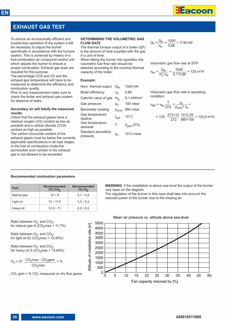
To ensure an economically efficient andtrouble-free operation of the system it willbe necessary to adjust the burnerspecifically in accordance with the furnacesystem. This is achieved by means of afuel-combustion air compound control unitwhich adjusts the burner to ensure aproper combustion. Exhaust gas tests arerequired for this purpose.The percentage CO2 and O2 and theexhaust gas temperature will have to bemeasured to determine the efficiency andcombustion quality.Prior to any measurement make sure tocheck the boiler and exhaust gas systemfor absence of leaks.
Secondary air will falsify the measuredresultsCheck that the exhaust gases have aresidual oxygen (O2) content as low aspossible and a carbon dioxide (CO2)content as high as possible.The carbon monoxide content of theexhaust gases must be below the currentlyapplicable specifications in all load stages.In the fuel oil combustion mode thepermissible soot number in the exhaustgas is not allowed to be exceeded
DETERMINING THE VOLUMETRIC GASFLOW RATEThe thermal furnace output of a boiler (QF)is the amount of heat supplied with the gasin a unit of time.When taking the burner into operation thevolumetric fuel flow rate should beselected according to the nominal thermalcapacity of the boiler.
Example:
Nom. thermal output QN 1000 kWBoiler efficiency nK 0,88Calorific value of gas Hu 9,1 kWh/m3
Gas pressure pU 100 mbarBarometer reading pamb 980 mbarGas temperaturerelative tgas 15°C
Gas temperatureabsolute T (tgas+273)
Standard atmosfericpressure pn 1013 mbar
0,88nK
Hu*nK 9,1*0,88
273 pamb+ pu
273 980+100
Recommended combustion parameters
Ratio between O2- and CO2- for natural gas H (CO2max = 11,7%)
Ratio between O2- and CO2- for light oil EL (CO2max = 15,40%)
Ratio between O2- and CO2- for heavy oil S (CO2max = 15,60%)
O2 = 21 CO2max - CO2gem = %CO2max
WARNING: if the installation is above sea level the output of the burnervary base on the diagram.The regulation of the burner in this case shall take into account thereduced power of the burner due to the missing air.
Fuel Recommended(%) CO2
Recommended(%) O2
Natural gas 10 ÷ 9 3,1 ÷ 4,8
Light oil 13 ÷ 11,5 3,3 ÷ 5,3
Heavy oil 12,5 ÷ 11 4,2 ÷ 6,2
00
500100015002000250030003500400045005000
5 10 15 20 25 30 35 40 45 50
Mean air pressure vs. altitude above sea-level
Fan capacity reduced by [%]
Altit
ude
of in
stal
latio
n si
te [m
]
CO2 gem = % CO2 measured on dry flue gases
21www.eacoon.com
EN
420010511800
START-UP
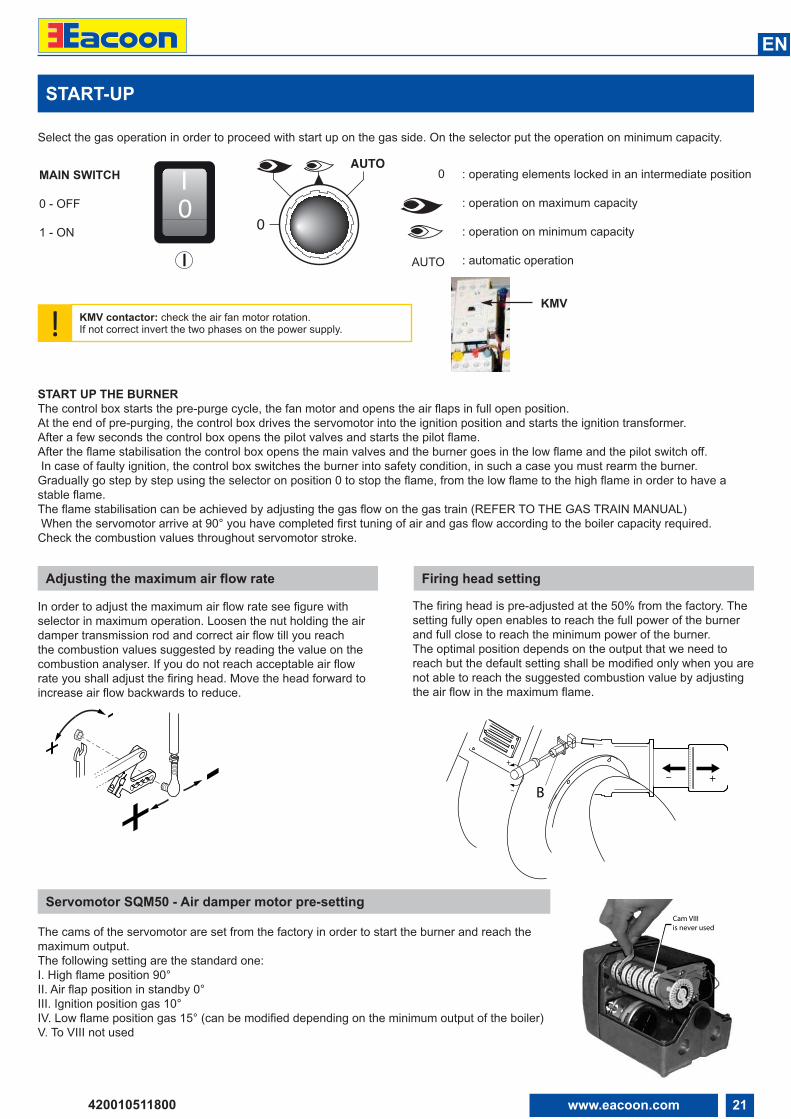
Select the gas operation in order to proceed with start up on the gas side. On the selector put the operation on minimum capacity.
! KMV contactor: check the air fan motor rotation. If not correct invert the two phases on the power supply.
Adjusting the maximum air flow rate
KMV
START UP THE BURNERThe control box starts the pre-purge cycle, the fan motor and opens the air flaps in full open position. At the end of pre-purging, the control box drives the servomotor into the ignition position and starts the ignition transformer.After a few seconds the control box opens the pilot valves and starts the pilot flame.After the flame stabilisation the control box opens the main valves and the burner goes in the low flame and the pilot switch off.In case of faulty ignition, the control box switches the burner into safety condition, in such a case you must rearm the burner.
Gradually go step by step using the selector on position 0 to stop the flame, from the low flame to the high flame in order to have astable flame. The flame stabilisation can be achieved by adjusting the gas flow on the gas train (REFER TO THE GAS TRAIN MANUAL)When the servomotor arrive at 90° you have completed first tuning of air and gas flow according to the boiler capacity required.
Check the combustion values throughout servomotor stroke.
Firing head setting
Servomotor SQM50 - Air damper motor pre-setting
The cams of the servomotor are set from the factory in order to start the burner and reach themaximum output.The following setting are the standard one:I. High flame position 90°II. Air flap position in standby 0°III. Ignition position gas 10°IV. Low flame position gas 15° (can be modified depending on the minimum output of the boiler)V. To VIII not used
Cam VIII is never used
: operating elements locked in an intermediate position
: operation on maximum capacity
: operation on minimum capacity
: automatic operation
0
AUTO0
AUTO
0IMAIN SWITCH
0 - OFF
1 - ON
In order to adjust the maximum air flow rate see figure withselector in maximum operation. Loosen the nut holding the airdamper transmission rod and correct air flow till you reachthe combustion values suggested by reading the value on thecombustion analyser. If you do not reach acceptable air flowrate you shall adjust the firing head. Move the head forward toincrease air flow backwards to reduce.
++ -
-
The firing head is pre-adjusted at the 50% from the factory. Thesetting fully open enables to reach the full power of the burnerand full close to reach the minimum power of the burner. The optimal position depends on the output that we need toreach but the default setting shall be modified only when you arenot able to reach the suggested combustion value by adjustingthe air flow in the maximum flame.
–
+
B+--
22 www.eacoon.com
EN
420010511800
0,40,6 0,9
3,0
1,5
2,1
1,82,42,7
1,2
A
B
C D
START-UP
Adjusting the intermediate burner capacity
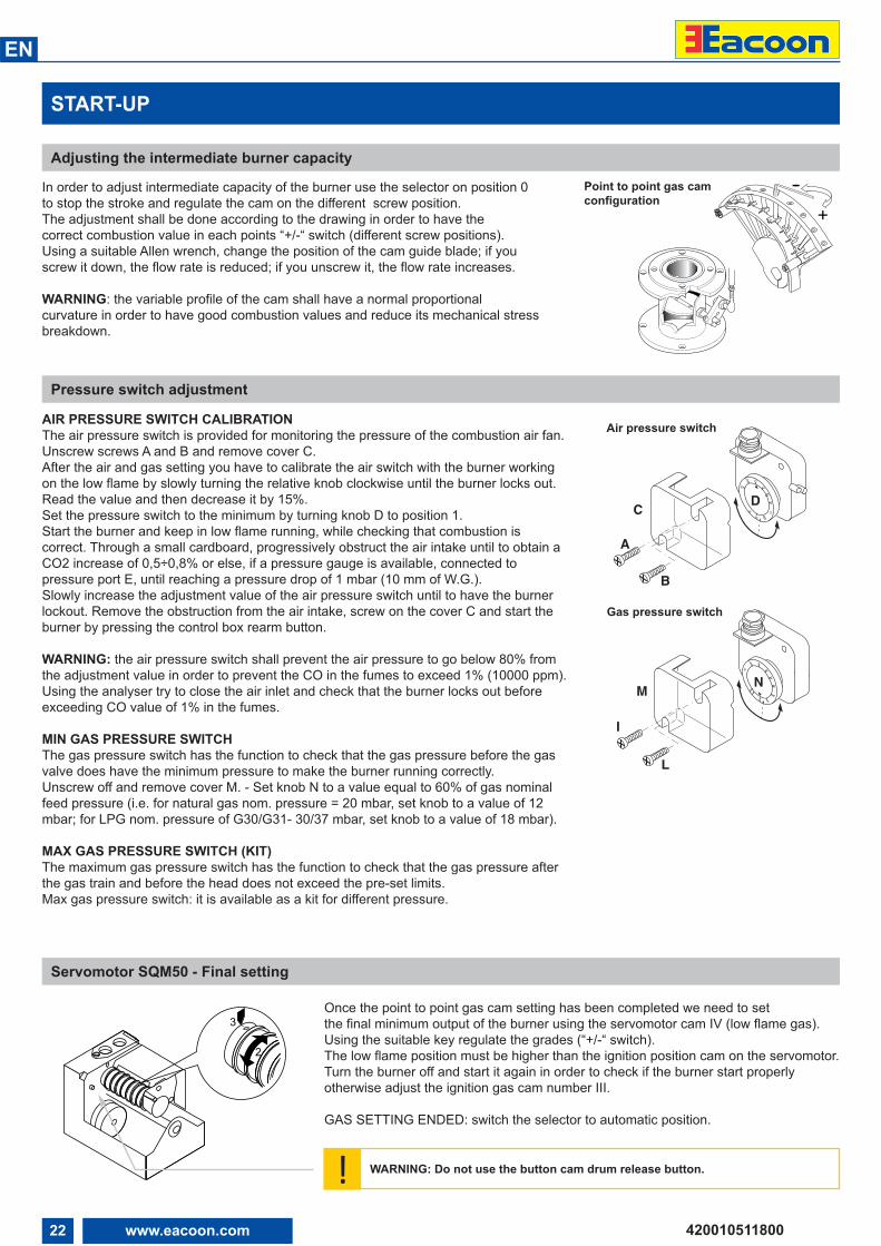
In order to adjust intermediate capacity of the burner use the selector on position 0 to stop the stroke and regulate the cam on the different screw position. The adjustment shall be done according to the drawing in order to have the correct combustion value in each points “+/-“ switch (different screw positions). Using a suitable Allen wrench, change the position of the cam guide blade; if youscrew it down, the flow rate is reduced; if you unscrew it, the flow rate increases.
WARNING: the variable profile of the cam shall have a normal proportional curvature in order to have good combustion values and reduce its mechanical stressbreakdown.
+--Point to point gas cam
configuration
Pressure switch adjustment
AIR PRESSURE SWITCH CALIBRATIONThe air pressure switch is provided for monitoring the pressure of the combustion air fan.Unscrew screws A and B and remove cover C.After the air and gas setting you have to calibrate the air switch with the burner workingon the low flame by slowly turning the relative knob clockwise until the burner locks out.Read the value and then decrease it by 15%. Set the pressure switch to the minimum by turning knob D to position 1.Start the burner and keep in low flame running, while checking that combustion iscorrect. Through a small cardboard, progressively obstruct the air intake until to obtain aCO2 increase of 0,5÷0,8% or else, if a pressure gauge is available, connected topressure port E, until reaching a pressure drop of 1 mbar (10 mm of W.G.).Slowly increase the adjustment value of the air pressure switch until to have the burnerlockout. Remove the obstruction from the air intake, screw on the cover C and start theburner by pressing the control box rearm button.
WARNING: the air pressure switch shall prevent the air pressure to go below 80% fromthe adjustment value in order to prevent the CO in the fumes to exceed 1% (10000 ppm).Using the analyser try to close the air inlet and check that the burner locks out beforeexceeding CO value of 1% in the fumes.
MIN GAS PRESSURE SWITCHThe gas pressure switch has the function to check that the gas pressure before the gasvalve does have the minimum pressure to make the burner running correctly.Unscrew off and remove cover M. - Set knob N to a value equal to 60% of gas nominalfeed pressure (i.e. for natural gas nom. pressure = 20 mbar, set knob to a value of 12mbar; for LPG nom. pressure of G30/G31- 30/37 mbar, set knob to a value of 18 mbar).
MAX GAS PRESSURE SWITCH (KIT)The maximum gas pressure switch has the function to check that the gas pressure afterthe gas train and before the head does not exceed the pre-set limits. Max gas pressure switch: it is available as a kit for different pressure.
Air pressure switch
Once the point to point gas cam setting has been completed we need to set the final minimum output of the burner using the servomotor cam IV (low flame gas). Using the suitable key regulate the grades (“+/-“ switch). The low flame position must be higher than the ignition position cam on the servomotor.Turn the burner off and start it again in order to check if the burner start properlyotherwise adjust the ignition gas cam number III.
GAS SETTING ENDED: switch the selector to automatic position.
Servomotor SQM50 - Final setting
! WARNING: Do not use the button cam drum release button.
2,5 510 15
50
25
35
30
4045
20
I
L
M N
Gas pressure switch
23www.eacoon.com
EN
420010511800
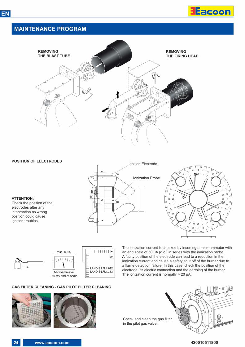
MAINTENANCE PROGRAM
!Burner and boiler servicing must only be carried out by authorised and qualified personnel at least once a year. Depending on the type of installation, shorter maintenance intervals may be necessary.The system operator is advised to take out a maintenance contract to guarantee regular servicing.WARNING: Use original spare parts.
SAFETY WARNINGS: 1. Turn off the power supply and protect the system from accidental start-up2. Cut gas supply3. Make sure there is no residual power in the system and that the actions in points 1and 2 have been completed.4. Before opening the burner casing, ensure that the fan motor has stopped completely
Failure to observe any of these instructions will result in the risk of death or injury!
WORKS RECOMMENDED AS PART OF ANNUAL BURNER MAINTENANCE:
• Emergency stop button function check• Check burner start characteristics• Run burner test and input measurement in the boiler room• Clean the combustion components and replace defective parts if necessary• Check the combustion head components and make sure that all components are in good condition otherwise replace them• Replace ignition electrodes if necessary and check their correct position after any intervention• Flame monitor and automatic combustion control unit function check• Clean the fan wheel and the housing and grease rotating parts if necessary• Perform visual inspection of gas lines in the boiler room and check the gas flow• Clean the gas filter cartridge with air periodically, replace it if necessary• After the cleaning of the components of the gas train perform the leakage test• Make visual inspection of the burner’s electrical components and eliminate malfunctions if necessary• Burner safety devices function check (air pressure/gas pressure switches)• Commissioning the burner and correct the adjustment values if necessary
NOTES ON REASSEMBLING: Perform the described step in reverse order and make sure to refit components as they were originally assembled and the system is free from leaks. Use only original spare parts.
DRAW UP A MEASUREMENT REPORT ACCORDING TO THE LOCAL REGULATION AND CODES OF PRACTISE OF THECOUNTRY
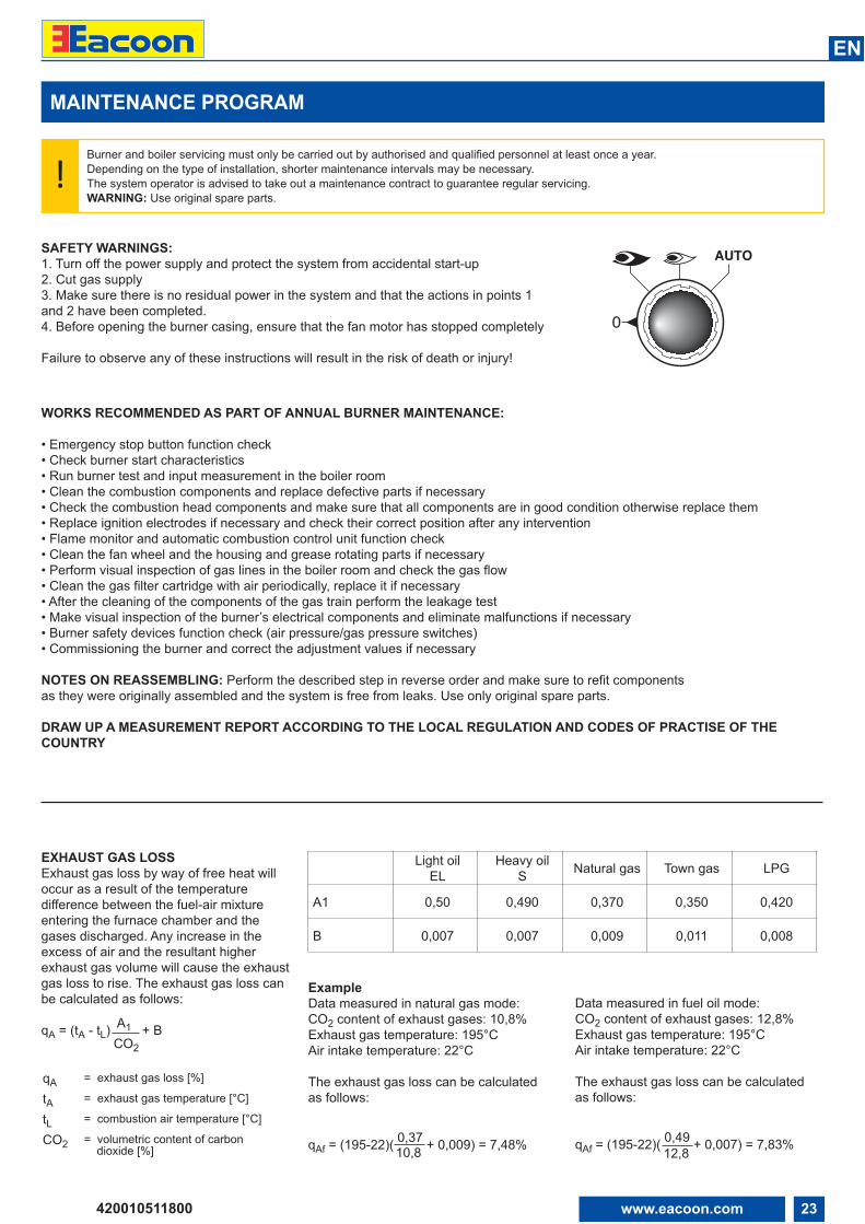
EXHAUST GAS LOSSExhaust gas loss by way of free heat willoccur as a result of the temperaturedifference between the fuel-air mixtureentering the furnace chamber and thegases discharged. Any increase in theexcess of air and the resultant higherexhaust gas volume will cause the exhaustgas loss to rise. The exhaust gas loss canbe calculated as follows:
qA = (tA - tL) A1 + BCO2
qA = exhaust gas loss [%]
tA = exhaust gas temperature [°C]
tL = combustion air temperature [°C]
CO2 = volumetric content of carbon dioxide [%]
ExampleData measured in natural gas mode:CO2 content of exhaust gases: 10,8%Exhaust gas temperature: 195°CAir intake temperature: 22°C
The exhaust gas loss can be calculated as follows:
qAf = (195-22)( 0,37 + 0,009) = 7,48%10,8
Data measured in fuel oil mode:CO2 content of exhaust gases: 12,8%Exhaust gas temperature: 195°CAir intake temperature: 22°C
The exhaust gas loss can be calculated as follows:
qAf = (195-22)( 0,49 + 0,007) = 7,83%12,8
Light oilEL
Heavy oilS Natural gas Town gas LPG
A1 0,50 0,490 0,370 0,350 0,420
B 0,007 0,007 0,009 0,011 0,008
0
AUTO
24 www.eacoon.com
EN
420010511800
MAINTENANCE PROGRAM
POSITION OF ELECTRODES
ATTENTION: Check the position of the electrodes after anyintervention as wrongposition could cause ignition troubles.
The ionization current is checked by inserting a microammeter withan end scale of 50 µA (d.c.) in series with the ionization probe.A faulty position of the electrode can lead to a reduction in the ionization current and cause a safety shut off of the burner due to a flame detection failure. In this case, check the position of the electrode, its electric connection and the earthing of the burner.The ionization current is normally > 20 µA.
24min. 6 µA
LANDIS LFL1.622LANDIS LFL1.333Microammeter
50 µA end of scale
GAS FILTER CLEANING - GAS PILOT FILTER CLEANING
Check and clean the gas filter in the pilot gas valve
REMOVINGTHE BLAST TUBE
REMOVINGTHE FIRING HEAD
510
Elettrodoaccensione
Elettrodorivelazione
Ignition Electrode
Ionization Probe
==
15
25www.eacoon.com
EN
420010511800
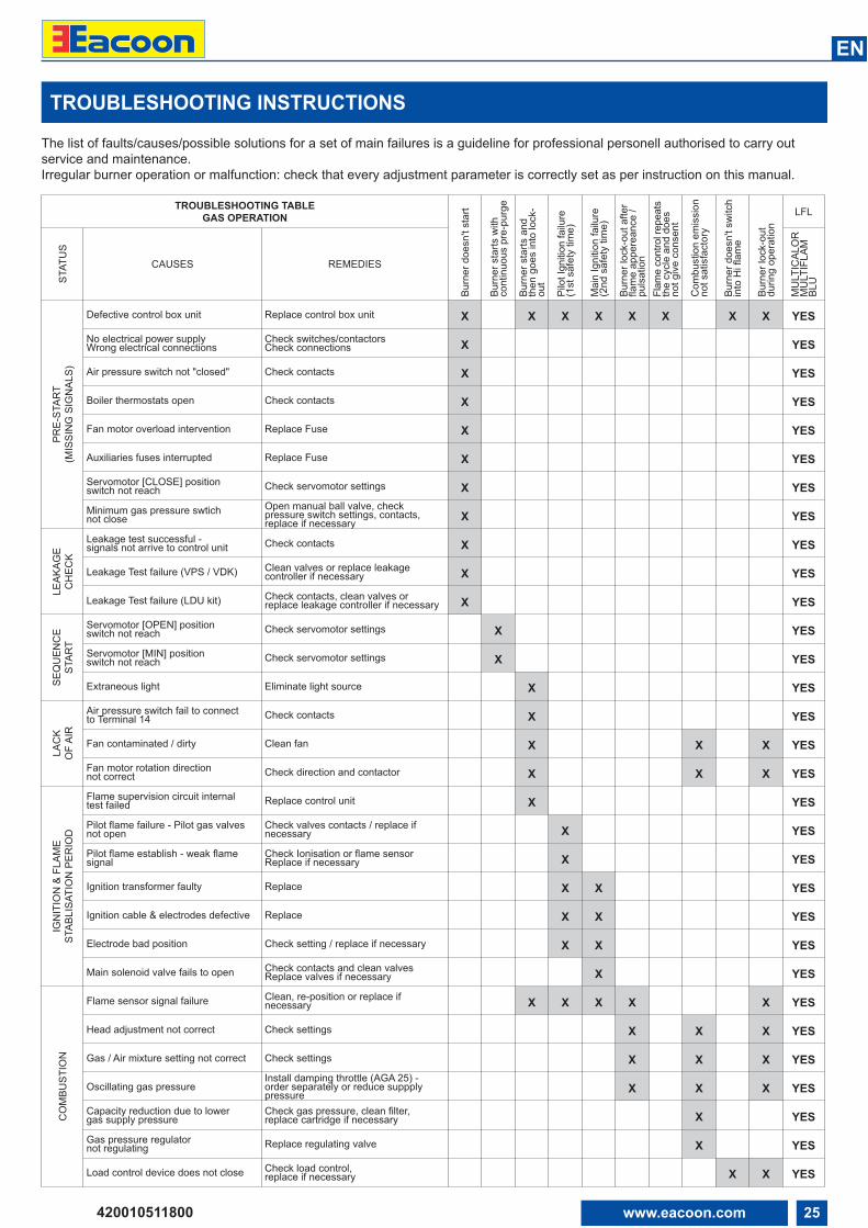
The list of faults/causes/possible solutions for a set of main failures is a guideline for professional personell authorised to carry outservice and maintenance. Irregular burner operation or malfunction: check that every adjustment parameter is correctly set as per instruction on this manual.
TROUBLESHOOTING INSTRUCTIONS
TROUBLESHOOTING TABLEGAS OPERATION
Burn
er d
oesn
't st
art
Burn
er s
tarts
with
cont
inuo
us p
re-p
urge
Burn
er s
tarts
and
then
goe
s in
to lo
ck-
out
Pilo
t Ign
ition
failu
re
(1st
saf
ety
time)
Mai
n Ig
nitio
n fa
ilure
(2
nd s
afet
y tim
e)
Burn
er lo
ck-o
ut a
fter
flam
e ap
pere
ance
/pu
lsat
ion
Flam
e co
ntro
l rep
eats
the
cycl
e an
d do
esno
t giv
e co
nsen
t
Com
bust
ion
emis
sion
not s
atis
fact
ory
Burn
er d
oesn
't sw
itch
into
Hi f
lam
e
Burn
er lo
ck-o
utdu
ring
oper
atio
n
LFL
STAT
US
CAUSES REMEDIES
MU
LTIC
ALO
RM
ULT
IFLA
MBL
U
PRE-
STAR
T (M
ISSI
NG
SIG
NAL
S)
Defective control box unit Replace control box unit X X X X X X X X YES
No electrical power supplyWrong electrical connections
Check switches/contactorsCheck connections X YES
Air pressure switch not "closed" Check contacts X YES
Boiler thermostats open Check contacts X YES
Fan motor overload intervention Replace Fuse X YES
Auxiliaries fuses interrupted Replace Fuse X YES
Servomotor [CLOSE] position switch not reach Check servomotor settings X YES
Minimum gas pressure swtich not close
Open manual ball valve, check pressure switch settings, contacts, replace if necessary X YES
LEAK
AGE
CH
ECK
Leakage test successful - signals not arrive to control unit Check contacts X YES
Leakage Test failure (VPS / VDK) Clean valves or replace leakagecontroller if necessary X YES
Leakage Test failure (LDU kit) Check contacts, clean valves or replace leakage controller if necessary X YES
SEQ
UEN
CE
STAR
T
Servomotor [OPEN] position switch not reach Check servomotor settings X YES
Servomotor [MIN] position switch not reach Check servomotor settings X YES
Extraneous light Eliminate light source X YES
LAC
K O
F AI
R
Air pressure switch fail to connect to Terminal 14 Check contacts X YES
Fan contaminated / dirty Clean fan X X X YES
Fan motor rotation direction not correct Check direction and contactor X X X YES
IGN
ITIO
N &
FLA
ME
STAB
LISA
TIO
N P
ERIO
D
Flame supervision circuit internal test failed Replace control unit X YES
Pilot flame failure - Pilot gas valvesnot open
Check valves contacts / replace ifnecessary X YES
Pilot flame establish - weak flamesignal
Check Ionisation or flame sensorReplace if necessary X YES
Ignition transformer faulty Replace X X YES
Ignition cable & electrodes defective Replace X X YES
Electrode bad position Check setting / replace if necessary X X YES
Main solenoid valve fails to open Check contacts and clean valvesReplace valves if necessary X YES
CO
MBU
STIO
N
Flame sensor signal failure Clean, re-position or replace ifnecessary X X X X X YES
Head adjustment not correct Check settings X X X YES
Gas / Air mixture setting not correct Check settings X X X YES
Oscillating gas pressureInstall damping throttle (AGA 25) - order separately or reduce suppplypressure X X X YES
Capacity reduction due to lower gas supply pressure
Check gas pressure, clean filter, replace cartridge if necessary X YES
Gas pressure regulator not regulating Replace regulating valve X YES
Load control device does not close Check load control, replace if necessary X X YES
26 www.eacoon.com
EN
420010511800
OPERATING TROUBLE
In case of operating trouble it should bechecked whether the system is in properworking order.
Make a check for the following:1. Availability of fuel. Availability of gas in the line at sufficientlyhigh pressure. Correct position of fuel selector switch.2. Availability of electric power in theburner system.3. Proper functional order and setting of allcontrol and safety instruments such as
temperature controller, safety limiter, waterfailure cut-out, electrical limit switches, etc.If the trouble is not found to be due to anyof the above-mentioned points it will benecessary to test the burner functions verycarefully.
Prevailing conditions:The burner will be found to be out ofoperation and in faulty and interlockedposition.Proceed with searching for the cause ofthe trouble and eliminate it. Unlock the
control box by pressing the fault eliminatekey and start the burner.Do not press the fault eliminate key longerthan 10 seconds.The start-up program will be initiated andshould be carefully monitored. The possible cause of the fault may bequickly found by reference to the faultindicator of the control box and watchingthe start-up and operating program.
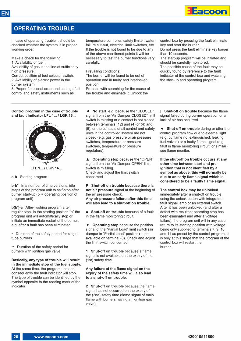
Control program in the case of troubleand fault indicator LFL 1... / LGK 16...
LFL 1... / LGK 16...
a-b Starting program
b-b’ In a number of time versions; idle steps of the program unit to self-stop afterburner start-up (b’ = operating position ofprogram unit)
b(b’)-a After-flushing program after regular stop. In the starting position “a” theprogram unit will automatically stop orinitiate an immediate restart of the burner,e.g. after a fault has been eliminated
• Duration of the safety period for single-tube burners
•• Duration of the safety period forburners with ignition gas valve
Basically, any type of trouble will resultin the immediate stop of the fuel supply.At the same time, the program unit andconsequently the fault indicator will stop.The type of trouble can be identified by thesymbol opposite to the reading mark of theindicator:
◄ No start, e.g. because the “CLOSED”signal from the “Air Damper CLOSED” limitswitch is missing or a contact is not closedbetween terminals (12) and (4) or (4) and(5); or the contacts of all control and safetyunits in the controlled system are notclosed (e.g. gas pressure or air pressureswitches, temperature or pressureswitches, temperature or pressureregulators).
▲ Operating stop because the “OPEN”signal from the “Air Damper OPEN” limitswitch is missing. Check and adjust the limit switchconcerned.
P Shut-off on trouble because there isnot air pressure signal at the beginning ofthe air pressure check. Any air pressure failure after this timewill also lead to a shut-off on trouble.
■ Shut-off on trouble because of a faultin the flame monitoring circuit.
▼ Operating stop because the positionsignal of the “Partial Load” limit switch (airdamper in “Partial Load” position) is notavailable on terminal (8). Check and adjustthe limit switch concerned.
1 Shut-off on trouble because a flamesignal is not available on the expiry of the(1st) safety time.
Any failure of the flame signal on theexpiry of the safety time will also leadto a shut-off on trouble.
2 Shut-off on trouble because the flamesignal has not occurred on the expiry ofthe (2nd) safety time (flame signal of mainflame with burners having an ignition gasvalve).
| Shut-off on trouble because the flamesignal failed during burner operation or alack of air has occurred.
◄ Shut-off on trouble during or after thecontrol program flow due to external light(e.g. by flame not extinguished, leakingfuel valves) or a faulty flame signal (e.g.fault in flame monitoring circuit, or similar);see flame monitor.
If the shut-off on trouble occurs at anyother time between start and pre-ignition that is not identified by asymbol as above, this will normally bedue to an early flame signal which isconsidered to be a faulty flame signal.
The control box may be unlockedimmediately after a shut-off on troubleusing the unlock button with integratedfault signal lamp or an external switch.After it has been unlocked (and after adefect with resultant operating stop hasbeen eliminated and after a voltagefailure), the program unit will in any casereturn to its starting position with voltagebeing only supplied to terminals 7, 9, 10and 11 as preset by the control program. Itis only at this stage that the program of thecontrol box will restart the burner.
27www.eacoon.com
EN
420010511800
APPENDIX
Control box - Damper actuators
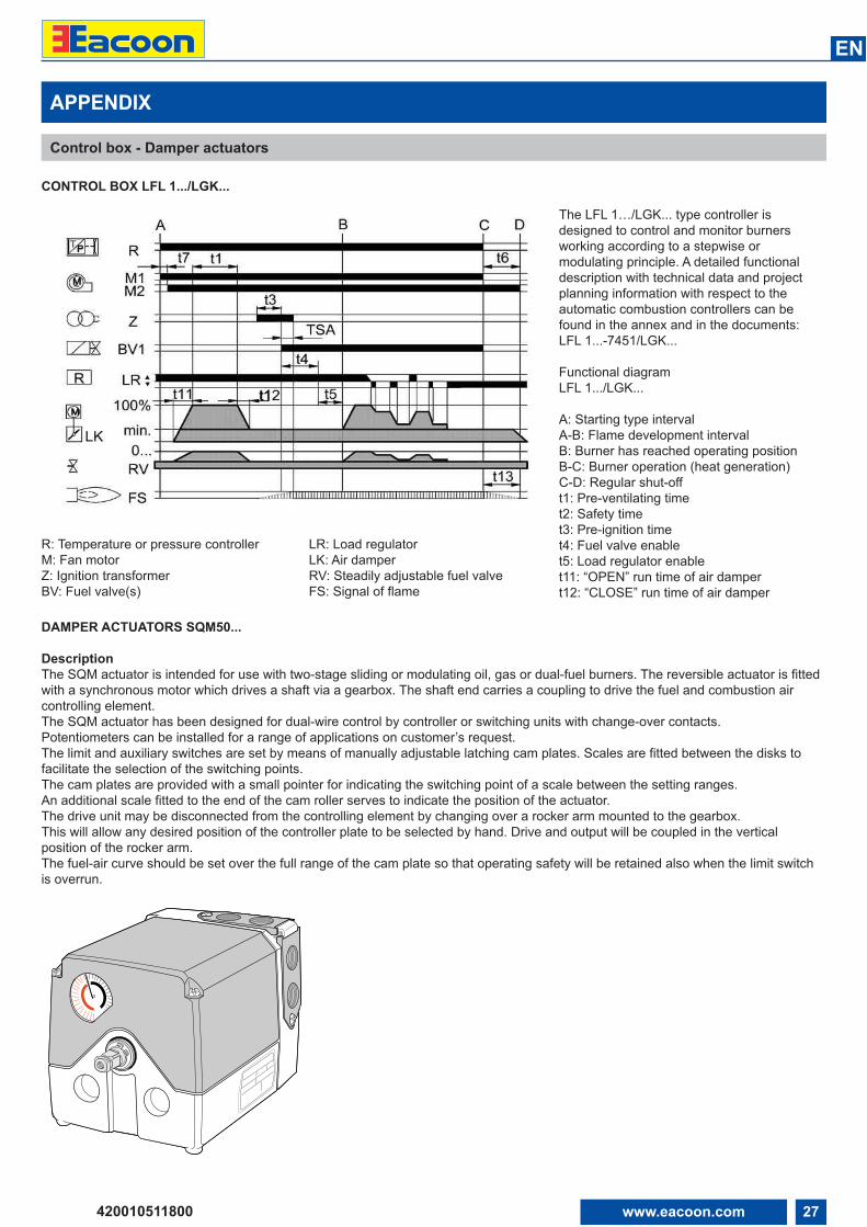
CONTROL BOX LFL 1.../LGK...
R: Temperature or pressure controllerM: Fan motorZ: Ignition transformerBV: Fuel valve(s)
LR: Load regulatorLK: Air damperRV: Steadily adjustable fuel valveFS: Signal of flame
The LFL 1…/LGK... type controller isdesigned to control and monitor burnersworking according to a stepwise ormodulating principle. A detailed functionaldescription with technical data and projectplanning information with respect to theautomatic combustion controllers can befound in the annex and in the documents:LFL 1...-7451/LGK...
Functional diagramLFL 1.../LGK...
A: Starting type intervalA-B: Flame development intervalB: Burner has reached operating positionB-C: Burner operation (heat generation)C-D: Regular shut-offt1: Pre-ventilating timet2: Safety timet3: Pre-ignition timet4: Fuel valve enablet5: Load regulator enablet11: “OPEN” run time of air dampert12: “CLOSE” run time of air damper
DAMPER ACTUATORS SQM50...
DescriptionThe SQM actuator is intended for use with two-stage sliding or modulating oil, gas or dual-fuel burners. The reversible actuator is fittedwith a synchronous motor which drives a shaft via a gearbox. The shaft end carries a coupling to drive the fuel and combustion aircontrolling element.The SQM actuator has been designed for dual-wire control by controller or switching units with change-over contacts. Potentiometers can be installed for a range of applications on customer’s request.The limit and auxiliary switches are set by means of manually adjustable latching cam plates. Scales are fitted between the disks tofacilitate the selection of the switching points.The cam plates are provided with a small pointer for indicating the switching point of a scale between the setting ranges.An additional scale fitted to the end of the cam roller serves to indicate the position of the actuator.The drive unit may be disconnected from the controlling element by changing over a rocker arm mounted to the gearbox.This will allow any desired position of the controller plate to be selected by hand. Drive and output will be coupled in the verticalposition of the rocker arm.The fuel-air curve should be set over the full range of the cam plate so that operating safety will be retained also when the limit switchis overrun.
28 www.eacoon.com
EN
420010511800
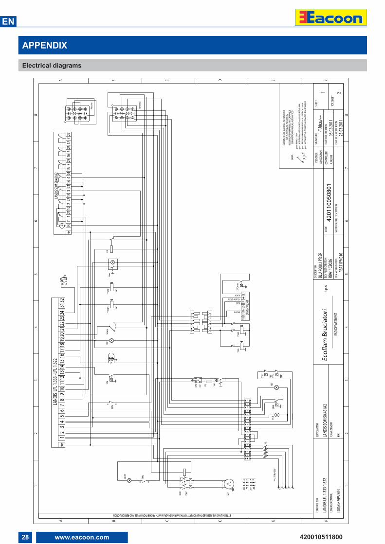
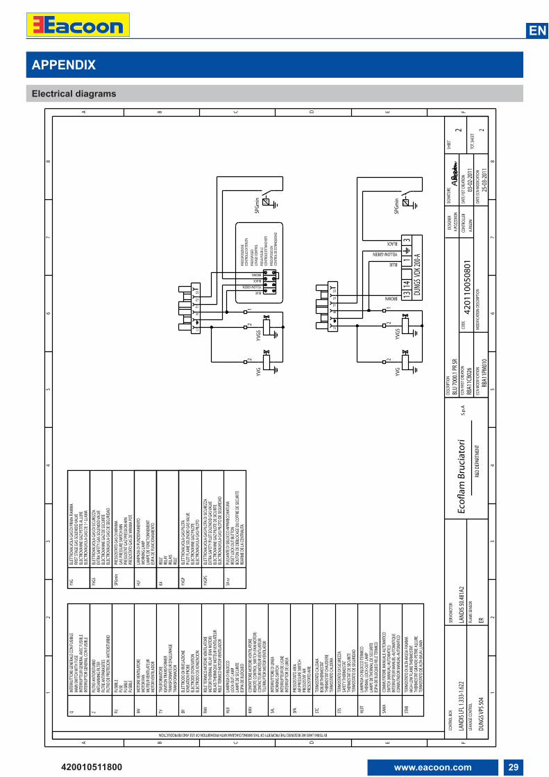
APPENDIX
Electrical diagrams
TOT.
SHEE
T
SHEE
TDE
SIGNE
RDE
SCRIP
TION
DATE
FIST
CREA
TION
CODE
SIGNA
TURE
R&D
DEPA
RTME
NT
CONT
ROLL
EREc
oflam
Bru
ciat
ori
SERV
OMOT
OR
FLAM
E SEN
SOR
S.p.
AEC
N FIR
ST CR
EATIO
N
BY TERM LAWS WE RESERVED THE PROPERTY OF THIS WIRING DIAGRAM WITH PROHIBITION OF USE AND REPRODUCTION
LEAK
AGE C
ONTR
OL
CONT
ROL B
OX
DATE
ECN
MODI
CATIO
NMO
DIFIC
ATIO
N DE
SCRIP
TION
ECN
MODI
FICAT
ION
BLU
7000
.1 PR
SRA.P
OZZO
BON
03-02
-2011
2
4201
1005
0801
1 A
.RIGO
NI
LAND
IS SQ
M 50
.481A
2
ER
RBA1
1CB0
26LA
NDIS
LFL 1
.333-1
.622
DUNG
S VPS
504
25-03
-2011
RBA1
1PM0
10
F
1
ED
23
4
CBA
12
34
56
78
FED
56
7
CB
8
A
98
745
6
21
3
1110
121012
11
13
2
45
6 98
7
FMV
97 98
FMV95 96
21
2
PT
STC PT
STS
SA s.
r
TP
STAB
HLF
400V
230V
FMV
3M
MV
UV
W
KMV
RS
TNO
LINE
LOAD
Z
FU SAL
HLBT
TP
SPA
TV
ER
SAM
A
12
30
KA
YVGS
YVG
TP
SPGm
in
HLB
HLF
YVGP
SYV
GP
SAM
A
12
30
pos 0
: FER
MO
/ STO
P
pos 2
: BAS
SA FI
AMM
A/LO
W FL
AME/
1re A
LLUR
E/BA
JA LL
AMA
pos 3
: AUT
OMAT
ICO/
AUTO
MAT
IC/A
UTOM
ATIQ
UE/A
UTOM
ATIC
O
pos 1
: ALT
A FIA
MM
A/HI
GH FL
AME/
2meA
LLUR
E/AL
TA LL
AMA
COM
MUT
ATOR
E MAN
UALE
-AUT
OMAT
ICO
CONM
UTAD
OR M
ANUA
L-AUT
OMAT
ICO
INTE
RRRU
PTEU
R MAN
UEL-A
UTOM
ATIQ
UESW
ITCH
MAN
UAL-A
UTOM
ATIC
9
Q
NR
ST
76
58
S NTRPE
50 H
z 400
V
1312
1110
12
43
512
LAND
IS LF
L 1.33
3 - LF
L 1.62
27
68
109
1115
1413
1716
1831
2220
1921
2324
32LA
NDIS S
QM 50
.481A
2
N1M
2111
112
23
1322
2314
2715
244
525
266
1617
7
L1T1
NT2
S3
YELLOW-GREEN
BLACK
BROWN
BLUE
DUNG
S VPS
504T7
T8B5
T6N
L1
L1S3
NT1
T2
41
23
Fem
mina
Mas
chio
29www.eacoon.com
EN
420010511800
12
2
12
2
F
1
ED
23
4
CBA
12
34
56
78
FED
56
7
CB
8
A
TOT.
SHEE
T
SHEE
TDE
SIGNE
RDE
SCRIP
TION
DATE
FIST
CREA
TION
CODE
SIGNA
TURE
R&D
DEPA
RTME
NT
CONT
ROLL
EREc
oflam
Bru
ciat
ori
SERV
OMOT
OR
FLAM
E SEN
SOR
S.p.
AEC
N FIR
ST CR
EATIO
N
BY TERM LAWS WE RESERVED THE PROPERTY OF THIS WIRING DIAGRAM WITH PROHIBITION OF USE AND REPRODUCTION
LEAK
AGE C
ONTR
OL
CONT
ROL B
OX
DATE
ECN
MODI
CATIO
NMO
DIFIC
ATIO
N DE
SCRIP
TION
ECN
MODI
FICAT
ION
BLU
7000
.1 PR
SRA.P
OZZO
BON
03-02
-2011
2
4201
1005
0801
2 A
.RIGO
NI
LAND
IS 50
.481A
2
ER
RBA1
1CB0
26LA
NDIS
LFL 1
.333-1
.622
DUNG
S VPS
504
25-03
-2011
RBA1
1PM0
10
CONM
UTAD
OR M
ANUA
L-AUT
OMAT
ICO
COMM
UTAT
ORE M
ANUA
LE-A
UTOM
ATICO
SWITC
H (M
ANUA
L-AUT
OMAT
IC))
INTE
RRUP
TEUR
MAN
UEL-A
UTOM
ATIQ
UE
INTE
RRUP
TOR D
E LIN
EAIN
TERR
UPTE
UR D
E LIG
NEW
ORKIN
G SW
ITCH
PRES
OSTA
TO AI
REPR
ESSO
STAT
AIR
AIR P
RESS
URE S
WITC
H
TERM
OSTA
TO CA
LDER
ATH
ERMO
STAT
CHAU
DIER
EBO
ILER T
HERM
OSTA
T
TERM
OSTA
TO D
E SEG
URID
ADTH
ERMO
STAT
DE S
ECUR
ITESA
FETY
THER
MOST
AT
ESPIA
DE B
LOQU
EO RE
LE TE
RMICO
LAMP
E DE T
HERM
AL D
E SEC
URITE
THER
MAL L
OCK-
OUT L
AMP
LAMP
ADA D
I BLO
CCO
TERM
ICO
TERM
OSTA
TO D
I SICU
REZZ
A
TERM
OSTA
TO CA
LDAI
A
PRES
SOST
ATO
ARIA
INTE
RRUT
TORE
DI L
INEA
SAMA
HLBT
STS
STC
SPA
SAL
ELEC
TROD
O DE
IONI
ZACIO
NEL
ECTR
ODE D
'IONI
SATIO
NIO
NISA
TION
PROB
E
INTE
RRUP
TOR G
ENER
AL CO
N FU
SIBLE
INTE
RRUP
TEUR
GEN
ERAL
AVEC
FUSIB
LEMA
IN SW
ITCH W
ITH FU
SE
FILTR
O DE
PROT
ECIO
N AN
TIDIST
URBIO
FILTR
E ANT
IPARA
SITES
ANTJA
MMIN
G FIL
TER
FUSIB
LEFU
SIBLE
MOTO
R VEN
TILAD
ORMU
TEUR
VENT
ILATE
URMO
TOR F
AN
TRAN
SFOR
MADO
RTR
ANSF
ORMA
TEUR
D'AL
LUMA
GEIG
NITIO
N TRA
NSFO
RMER
ESPIA
DE B
LOQU
EOLA
MPE D
E SEC
URITE
LOCK
-OUT
LAMP
RELE
' TER
MICO
MOT
OR VE
NTILA
DOR
RELA
IS TH
ERMI
QUE M
OTEU
R VEN
TILAT
EUR
MOTO
R THE
RMAL
RELA
Y (FA
N MO
TOR)
TELE
RRUP
TOR M
OTOR
VENT
ILATO
RCO
NTAC
TEUR
MOT
EUR V
ENTIL
ATEU
RRE
MOTE
CONT
ROL S
WITC
H (FA
N MO
TOR)
CONT
ATTO
RE M
OTOR
E VEN
TILAT
ORE
LAMP
ADA D
I BLO
CCO
RELE
' TER
MICO
MOT
ORE V
ENTIL
ATOR
E
ELET
TROD
O DI
RIVE
LAZIO
NE
TRAS
FORM
ATOR
E
MOTO
RE VE
NTILA
TORE
FUSIB
ILE
FILTR
O AN
TIDIST
URBO
INTE
RRUT
TORE
GEN
ERAL
E CON
FUSIB
ILE
KMV
HLB
FMV
ERTVMVFUFU
SE
ZQ
ESPIA
DE F
UNCIO
NAMI
ENTO
LAMP
E DE F
ONCT
IONN
EMEN
T
LAMP
ADA D
I FUN
ZIONA
MENT
O
PRES
OSTA
TO G
AS D
E MIN
IMA P
OT.
HLF
WOR
KING
LAMP
GAS P
RESS
URE S
WITC
H MI
N
HIGH
-LOW
FLAM
E THE
RMOS
TAT
PRES
SOST
ATO
GAS D
I MIN
IMA
PRES
SOST
AT G
AZ PR
ESSIO
N MI
N
ELET
TROV
ALVO
LA G
AS D
I SICU
REZZ
AEX
TRA S
AFET
Y GAS
SOLE
NOID
VALV
EEL
ECTR
OVAN
NE G
AZ D
E SEC
URITE
ELEC
TROV
ALVU
LA G
AS D
E SEG
URID
AD
ELET
TROV
ALVO
LA G
AS D
I PRIM
A FIA
MMA
FIRST
STAG
E GAS
SOLE
NOID
VALV
EEL
ECTR
OVAN
NE G
AZ PE
TITE A
LLUR
EEL
ECTR
OVAL
VULA
GAS
DE 1
^ LLA
MA
THER
MOST
AT G
RAND
E-PET
IRE AL
LURE
TERM
OSTA
TO D
E ALTA
-BAJ
A LLA
MA
TERM
OSTA
TO D
I ALTA
-BAS
SA FI
AMMA
YVGS
SPGm
in
YVG
STAB
BLUE
YELLOW-GREEN
BLACK
BROWN
CONT
ROLE
D'ET
ANCH
EITI
CONT
ROL D
E EST
ANQU
IDAD
PRED
ISPOS
ICION
PREV
U PO
UR LE
PRED
ISPOS
EDLE
KAGE
CONT
ROL
PRED
ISPOS
IZION
ECO
NTRO
LLO
DI TE
NUTA
YVG
YVGS
TP
SPGm
in
YVGS
YVG
TP
SPGm
in
KARE
LE'
RELA
YRE
LAIS
RELE
'
YVGP
ELET
TROV
ALVO
LA G
AS PI
LOTA
PILOT
FLAM
E SOL
ENOI
D GA
S VAL
VEEL
ECTR
OVAN
NE G
AZ PI
LOTE
ELEC
TROV
ALVU
LA G
AS PI
LOTO
SA s.r
PULS
ANTE
DI S
BLOC
CO AP
PARE
CCHI
ATUR
ARE
SET L
OCK O
UT BU
TTON
BOUT
ON D
E DEB
LOCA
GE D
U CO
FFRE
DE S
ECUR
ITERE
ARME
DE L
A CEN
TRAL
ITA
YVGP
SEL
ETTR
OVAL
VOLA
GAS
PILO
TA D
I SICU
REZZ
AEX
TRA S
AFET
Y PILO
T SOL
ENOI
D GA
S VAL
VEEL
ECTR
OVAN
NE G
AZ PI
LOTE
DE S
ICURIT
EEL
ECTR
OVAL
VULA
GAS
PILO
TO D
E SEG
URID
AD
NL1
T2T1
S3 S3N
T1L1
T2
31
1413 DU
NGS V
DK 20
0-A
YELLOW-GREEN
BROWN
BLACK
BLUE
APPENDIX
Electrical diagrams
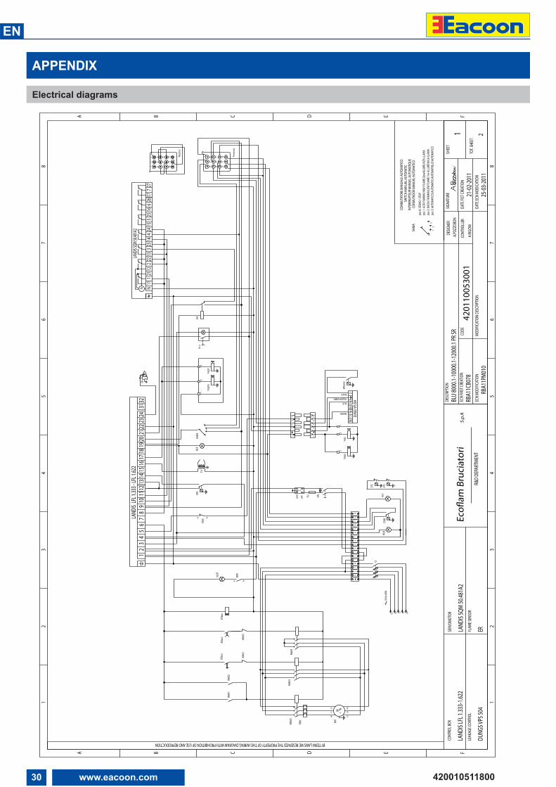
30 www.eacoon.com
EN
420010511800
TP
STAB
HLF
LINE
LOAD
Z
FU SAL
HLBT
TP
SPA
TV
ER
SAM
A
12
30
KA
YVG
YVGS
TP
SPGm
in
HLB
HLF
YVGP
SYV
GP
98
745
6
21
3
1110
121012
11
13
2
45
6 98
7
FMV
97 98
FMV95 96
21
2
PT
STC PT
STS
SA s.
r
F
1
ED
23
4
CBA
12
34
56
78
FED
56
7
CB
8
A
TOT.
SHEE
T
SHEE
TDE
SIGNE
RDE
SCRIP
TION
DATE
FIST
CREA
TION
CODE
SIGNA
TURE
R&D
DEPA
RTME
NT
CONT
ROLL
EREc
oflam
Bru
ciat
ori
SERV
OMOT
OR
FLAM
E SEN
SOR
S.p.
AEC
N FIR
ST CR
EATIO
N
BY TERM LAWS WE RESERVED THE PROPERTY OF THIS WIRING DIAGRAM WITH PROHIBITION OF USE AND REPRODUCTION
LEAK
AGE C
ONTR
OL
CONT
ROL B
OX
DATE
ECN
MODI
CATIO
NMO
DIFIC
ATIO
N DE
SCRIP
TION
ECN
MODI
FICAT
ION
BLU
8000
.1-10
000.1
-1200
0.1 PR
SRA.P
OZZO
BON
21-02
-2011
2
4201
1005
3001
1 A
.RIGO
NI
LAND
IS SQ
M 50
.481A
2
ER
RBA1
1CB0
78LA
NDIS
LFL 1
.333-1
.622
DUNG
S VPS
504
25-03
-2011
RBA1
1PM0
10
3M
MV
W1
V1U1
KMV2
FMV
KMV1
KMV3
KMV3
KMV1
KMV2
KMV1
KTav
vKT
avv
KTav
v
21
3
9
Q
NR
ST
76
58
S NTRPE
50 H
z 400
V
1312
1110
12
43
512
LAND
IS LF
L 1.33
3 - LF
L 1.62
27
68
109
1115
1413
1716
1831
2220
1921
2324
32LA
NDIS S
QM 50
.481A
2
N1M
2111
112
23
1322
2314
2715
244
525
266
1617
7
L1T1
NT2
S3
YELLOW-GREEN
BLACK
BROWN
BLUE
DUNG
S VPS
504T7
T8B5
T6N
L1
L1S3
NT1
T2
41
23
Fem
mina
Mas
chio
SWITC
H M
ANUA
L-AUT
OMAT
ICIN
TERR
RUPT
EUR M
ANUE
L-AUT
OMAT
IQUE
CONM
UTAD
OR M
ANUA
L-AUT
OMAT
ICO
COM
MUT
ATOR
E MAN
UALE
-AUT
OMAT
ICO
pos 1
: ALT
A FIA
MM
A/HI
GH FL
AME/
2meA
LLUR
E/AL
TA LL
AMA
pos 3
: AUT
OMAT
ICO/
AUTO
MAT
IC/A
UTOM
ATIQ
UE/A
UTOM
ATIC
Opo
s 2: B
ASSA
FIAM
MA/
LOW
FLAM
E/1r
e ALL
URE/
BAJA
LLAM
A
pos 0
: FER
MO
/ STO
P
SAM
A
12
30
W2
U2V2
APPENDIX
Electrical diagrams
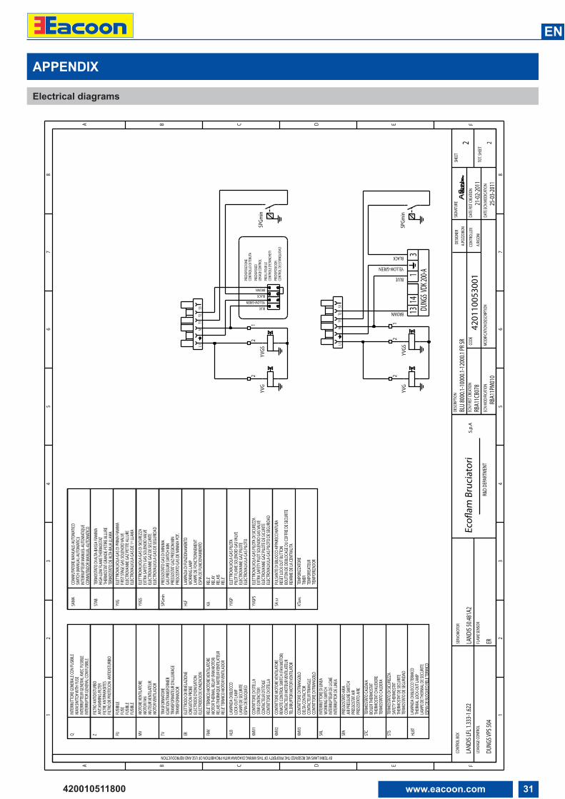
31www.eacoon.com
EN
420010511800
CONM
UTAD
OR M
ANUA
L-AUT
OMAT
ICO
COMM
UTAT
ORE M
ANUA
LE-A
UTOM
ATICO
SWITC
H (M
ANUA
L-AUT
OMAT
IC))
INTE
RRUP
TEUR
MAN
UEL-A
UTOM
ATIQ
UE
INTE
RRUP
TOR D
E LIN
EAIN
TERR
UPTE
UR D
E LIG
NEW
ORKIN
G SW
ITCH
PRES
OSTA
TO AI
REPR
ESSO
STAT
AIR
AIR P
RESS
URE S
WITC
H
TERM
OSTA
TO CA
LDER
ATH
ERMO
STAT
CHAU
DIER
EBO
ILER T
HERM
OSTA
T
TERM
OSTA
TO D
E SEG
URID
ADTH
ERMO
STAT
DE S
ECUR
ITESA
FETY
THER
MOST
AT
ESPIA
DE B
LOQU
EO RE
LE TE
RMICO
LAMP
E DE T
HERM
AL D
E SEC
URITE
THER
MAL L
OCK-
OUT L
AMP
LAMP
ADA D
I BLO
CCO
TERM
ICO
TERM
OSTA
TO D
I SICU
REZZ
A
TERM
OSTA
TO CA
LDAI
A
PRES
SOST
ATO
ARIA
INTE
RRUT
TORE
DI L
INEA
SAMA
HLBT
STS
STC
SPA
SAL
ELEC
TROD
O DE
IONI
ZACIO
NEL
ECTR
ODE D
'IONI
SATIO
NIO
NISA
TION
PROB
E
INTE
RRUP
TOR G
ENER
AL CO
N FU
SIBLE
INTE
RRUP
TEUR
GEN
ERAL
AVEC
FUSIB
LEMA
IN SW
ITCH W
ITH FU
SE
FILTR
O DE
PROT
ECIO
N AN
TIDIST
URBIO
FILTR
E ANT
IPARA
SITES
ANTJA
MMIN
G FIL
TER
FUSIB
LEFU
SIBLE
MOTO
R VEN
TILAD
ORMU
TEUR
VENT
ILATE
URMO
TOR F
AN
TRAN
SFOR
MADO
RTR
ANSF
ORMA
TEUR
D'AL
LUMA
GEIG
NITIO
N TRA
NSFO
RMER
ESPIA
DE B
LOQU
EOLA
MPE D
E SEC
URITE
LOCK
-OUT
LAMP
RELE
' TER
MICO
MOT
OR VE
NTILA
DOR
RELA
IS TH
ERMI
QUE M
OTEU
R VEN
TILAT
EUR
MOTO
R THE
RMAL
RELA
Y (FA
N MO
TOR)
TELE
RRUP
TOR M
OTOR
VENT
ILATO
RCO
NTAC
TEUR
MOT
EUR V
ENTIL
ATEU
RRE
MOTE
CONT
ROL S
WITC
H (FA
N MO
TOR)
LAMP
ADA D
I BLO
CCO
RELE
' TER
MICO
MOT
ORE V
ENTIL
ATOR
E
ELET
TROD
O DI
RIVE
LAZIO
NE
TRAS
FORM
ATOR
E
MOTO
RE VE
NTILA
TORE
FUSIB
ILE
FILTR
O AN
TIDIST
URBO
INTE
RRUT
TORE
GEN
ERAL
E CON
FUSIB
ILE
KMV1
HLB
FMV
ERTVMVFUFU
SE
ZQ
ESPIA
DE F
UNCIO
NAMI
ENTO
LAMP
E DE F
ONCT
IONN
EMEN
T
LAMP
ADA D
I FUN
ZIONA
MENT
O
PRES
OSTA
TO G
AS D
E MIN
IMA P
OT.
HLF
WOR
KING
LAMP
GAS P
RESS
URE S
WITC
H MI
N
HIGH
-LOW
FLAM
E THE
RMOS
TAT
PRES
SOST
ATO
GAS D
I MIN
IMA
PRES
SOST
AT G
AZ PR
ESSIO
N MI
N
ELET
TROV
ALVO
LA G
AS D
I SICU
REZZ
AEX
TRA S
AFET
Y GAS
SOLE
NOID
VALV
EEL
ECTR
OVAN
NE G
AZ D
E SEC
URITE
ELEC
TROV
ALVU
LA G
AS D
E SEG
URID
AD
ELET
TROV
ALVO
LA G
AS D
I PRIM
A FIA
MMA
FIRST
STAG
E GAS
SOLE
NOID
VALV
EEL
ECTR
OVAN
NE G
AZ PE
TITE A
LLUR
EEL
ECTR
OVAL
VULA
GAS
DE 1
^ LLA
MA
THER
MOST
AT G
RAND
E-PET
IRE AL
LURE
TERM
OSTA
TO D
E ALTA
-BAJ
A LLA
MA
TERM
OSTA
TO D
I ALTA
-BAS
SA FI
AMMA
YVGS
SPGm
in
YVG
STAB
BLUE
YELLOW-GREEN
BLACK
BROWN
CONT
ROLE
D'ET
ANCH
EITI
CONT
ROL D
E EST
ANQU
IDAD
PRED
ISPOS
ICION
PREV
U PO
UR LE
PRED
ISPOS
EDLE
KAGE
CONT
ROL
PRED
ISPOS
IZION
ECO
NTRO
LLO
DI TE
NUTA
YVG
YVGS
TP
SPGm
in
YVGS
YVG
TP
SPGm
in
KARE
LE'
RELA
YRE
LAIS
RELE
'
YVGP
ELET
TROV
ALVO
LA G
AS PI
LOTA
PILOT
FLAM
E SOL
ENOI
D GA
S VAL
VEEL
ECTR
OVAN
NE G
AZ PI
LOTE
ELEC
TROV
ALVU
LA G
AS PI
LOTO
SA s.r
PULS
ANTE
DI S
BLOC
CO AP
PARE
CCHI
ATUR
ARE
SET L
OCK O
UT BU
TTON
BOUT
ON D
E DEB
LOCA
GE D
U CO
FFRE
DE S
ECUR
ITERE
ARME
DE L
A CEN
TRAL
ITA
YVGP
SEL
ETTR
OVAL
VOLA
GAS
PILO
TA D
I SICU
REZZ
AEX
TRA S
AFET
Y PILO
T SOL
ENOI
D GA
S VAL
VEEL
ECTR
OVAN
NE G
AZ PI
LOTE
DE S
ICURIT
EEL
ECTR
OVAL
VULA
GAS
PILO
TO D
E SEG
URID
AD
KMV2
CONT
ATTO
RE M
OTOR
E VEN
TILAT
ORE
KMV3
CONT
ATTO
RE D
I TRIA
NGOL
ODE
LTA CO
NTAC
TOR
CONT
ACTE
UR TR
IANG
LECO
NTAT
TORE
DI T
RIANG
OLO
CONT
ATTO
RE D
I STE
LLA
STAR
CONT
ACTO
RCO
NTAC
TEUR
D'ET
OILE
CONT
ATTO
RE D
I STE
LLA
KTav
v.TE
MPOR
IZZAT
ORE
TIMER
TEMP
ORISA
TEUR
TIEMP
ORIZA
DOR
12
2
12
2
F
1
ED
23
4
CBA
12
34
56
78
FED
56
7
CB
8
A
TOT.
SHEE
T
SHEE
TDE
SIGNE
RDE
SCRIP
TION
DATE
FIST
CREA
TION
CODE
SIGNA
TURE
R&D
DEPA
RTME
NT
CONT
ROLL
EREc
oflam
Bru
ciat
ori
SERV
OMOT
OR
FLAM
E SEN
SOR
S.p.
AEC
N FIR
ST CR
EATIO
N
BY TERM LAWS WE RESERVED THE PROPERTY OF THIS WIRING DIAGRAM WITH PROHIBITION OF USE AND REPRODUCTION
LEAK
AGE C
ONTR
OL
CONT
ROL B
OX
DATE
ECN
MODI
CATIO
NMO
DIFIC
ATIO
N DE
SCRIP
TION
ECN
MODI
FICAT
ION
BLU
8000
.1-10
000.1
-1200
0.1 PR
SRA.P
OZZO
BON
21-02
-2011
2
4201
1005
3001
2 A
.RIGO
NI
LAND
IS 50
.481A
2
ER
RBA1
1CB0
78LA
NDIS
LFL 1
.333-1
.622
DUNG
S VPS
504
25-03
-2011
RBA1
1PM0
10
NL1
T2T1
S3 S3N
T1L1
T2
31
1413 DU
NGS V
DK 20
0-A
YELLOW-GREEN
BROWN
BLACK
BLUE
APPENDIX
Electrical diagrams
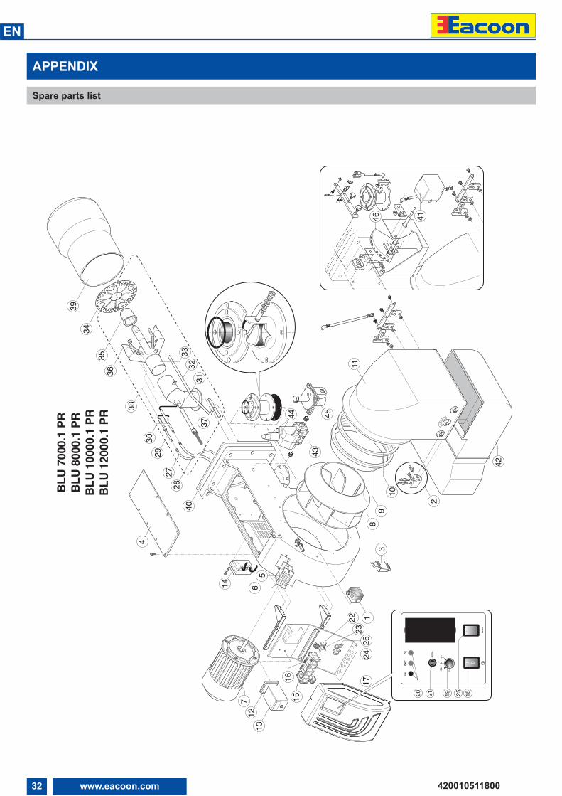
32 www.eacoon.com
EN
420010511800
APPENDIX
Spare parts list
BLU
7000
.1 PR
BLU
8000
.1 PR
BLU
1000
0.1 P
RBL
U 12
000.1
PR
4
8940
41
2827
3029
3435
36
38
39
31
5
42
3231
33
2
6
10
11
14
37
43
44
0 15
30
45
60 75 90
0I
GAS
RESE
T
1819 251516 17
24
20
26
21
0
AUTO
22
FINDE
RFIN
DER
23
127
13
PGM
EXIT
45
46
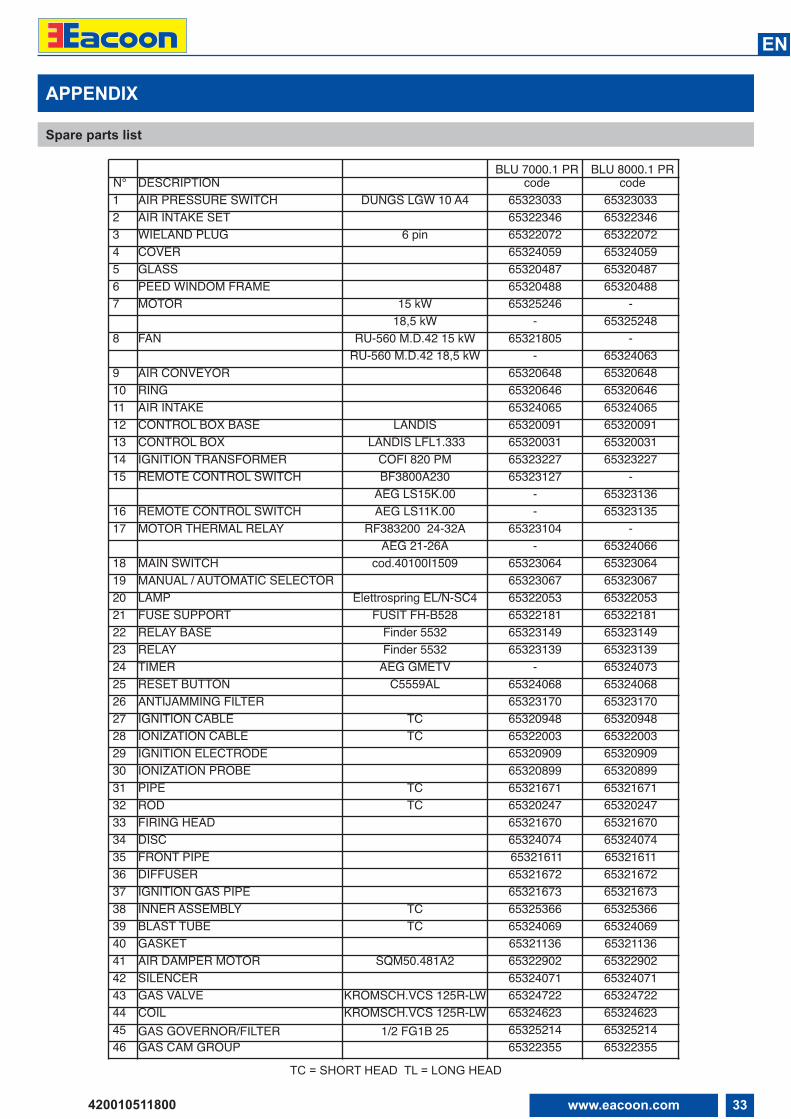
33www.eacoon.com
EN
420010511800
APPENDIX
Spare parts list
TC = SHORT HEAD TL = LONG HEAD
BLU 7000.1 PR BLU 8000.1 PRN° DESCRIPTION code code1 AIR PRESSURE SWITCH DUNGS LGW 10 A4 65323033 653230332 AIR INTAKE SET 65322346 653223463 WIELAND PLUG 6 pin 65322072 653220724 COVER 65324059 653240595 GLASS 65320487 653204876 PEED WINDOM FRAME 65320488 653204887 MOTOR 15 kW 65325246 -
18,5 kW - 653252488 FAN RU-560 M.D.42 15 kW 65321805 -
RU-560 M.D.42 18,5 kW - 653240639 AIR CONVEYOR 65320648 6532064810 RING 65320646 6532064611 AIR INTAKE 65324065 6532406512 CONTROL BOX BASE LANDIS 65320091 6532009113 CONTROL BOX LANDIS LFL1.333 65320031 6532003114 IGNITION TRANSFORMER COFI 820 PM 65323227 6532322715 REMOTE CONTROL SWITCH BF3800A230 65323127 -
AEG LS15K.00 - 6532313616 REMOTE CONTROL SWITCH AEG LS11K.00 - 6532313517 MOTOR THERMAL RELAY RF383200 24-32A 65323104 -
AEG 21-26A - 6532406618 MAIN SWITCH cod.40100I1509 65323064 6532306419 MANUAL / AUTOMATIC SELECTOR 65323067 6532306720 LAMP Elettrospring EL/N-SC4 65322053 6532205321 FUSE SUPPORT FUSIT FH-B528 65322181 6532218122 RELAY BASE Finder 5532 65323149 6532314923 RELAY Finder 5532 65323139 6532313924 TIMER AEG GMETV - 6532407325 RESET BUTTON C5559AL 65324068 6532406826 ANTIJAMMING FILTER 65323170 6532317027 IGNITION CABLE TC 65320948 6532094828 IONIZATION CABLE TC 65322003 6532200329 IGNITION ELECTRODE 65320909 6532090930 IONIZATION PROBE 65320899 6532089931 PIPE TC 65321671 6532167132 ROD TC 65320247 6532024733 FIRING HEAD 65321670 6532167034 DISC 65324074 6532407435 FRONT PIPE 65321611 6532161136 DIFFUSER 65321672 6532167237 IGNITION GAS PIPE 65321673 6532167338 INNER ASSEMBLY TC 65325366 6532536639 BLAST TUBE TC 65324069 6532406940 GASKET 65321136 6532113641 AIR DAMPER MOTOR SQM50.481A2 65322902 6532290242 SILENCER 65324071 6532407143 GAS VALVE KROMSCH.VCS 125R-LW 65324722 6532472244 COIL KROMSCH.VCS 125R-LW 65324623 6532462345 GAS GOVERNOR/FILTER 1/2 FG1B 25 65325214 6532521446 GAS CAM GROUP 65322355 65322355
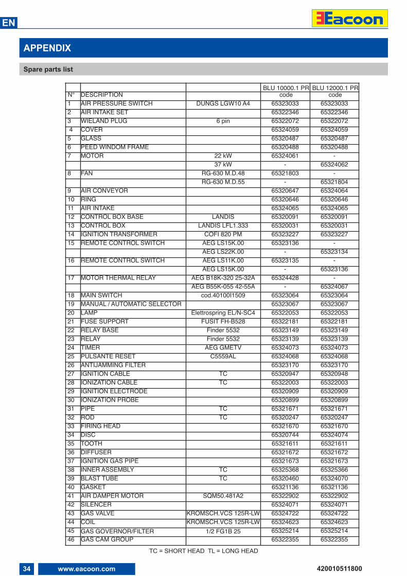
34 www.eacoon.com
EN
420010511800
BLU 10000.1 PR BLU 12000.1 PRN° DESCRIPTION code code1 AIR PRESSURE SWITCH DUNGS LGW10 A4 65323033 653230332 AIR INTAKE SET 65322346 653223463 WIELAND PLUG 6 pin 65322072 653220724 COVER 65324059 65324059
5 GLASS 65320487 653204876 PEED WINDOM FRAME 65320488 653204887 MOTOR 22 kW 65324061 -
37 kW - 653240628 FAN RG-630 M.D.48 65321803 -
RG-630 M.D.55 - 653218049 AIR CONVEYOR 65320647 6532406410 RING 65320646 6532064611 AIR INTAKE 65324065 6532406512 CONTROL BOX BASE LANDIS 65320091 6532009113 CONTROL BOX LANDIS LFL1.333 65320031 6532003114 IGNITION TRANSFORMER COFI 820 PM 65323227 6532322715 REMOTE CONTROL SWITCH AEG LS15K.00 65323136 -
AEG LS22K.00 - 6532313416 REMOTE CONTROL SWITCH AEG LS11K.00 65323135 -
AEG LS15K.00 - 6532313617 MOTOR THERMAL RELAY AEG B18K-320 25-32A 65324428 -
AEG B55K-055 42-55A - 6532406718 MAIN SWITCH cod.40100I1509 65323064 6532306419 MANUAL / AUTOMATIC SELECTOR 65323067 6532306720 LAMP Elettrospring EL/N-SC4 65322053 6532205321 FUSE SUPPORT FUSIT FH-B528 65322181 6532218122 RELAY BASE Finder 5532 65323149 6532314923 RELAY Finder 5532 65323139 6532313924 TIMER AEG GMETV 65324073 6532407325 PULSANTE RESET C5559AL 65324068 6532406826 ANTIJAMMING FILTER 65323170 6532317027 IGNITION CABLE TC 65320947 6532094828 IONIZATION CABLE TC 65322003 6532200329 IGNITION ELECTRODE 65320909 6532090930 IONIZATION PROBE 65320899 6532089931 PIPE TC 65321671 6532167132 ROD TC 65320247 6532024733 FIRING HEAD 65321670 6532167034 DISC 65320744 6532407435 TOOTH 65321611 6532161136 DIFFUSER 65321672 6532167237 IGNITION GAS PIPE 65321673 6532167338 INNER ASSEMBLY TC 65325368 6532536639 BLAST TUBE TC 65320460 6532407040 GASKET 65321136 6532113641 AIR DAMPER MOTOR SQM50.481A2 65322902 6532290242 SILENCER 65324071 6532407143 GAS VALVE KROMSCH.VCS 125R-LW 65324722 6532472244 COIL KROMSCH.VCS 125R-LW 65324623 6532462345 GAS GOVERNOR/FILTER 1/2 FG1B 25 65325214 6532521446 GAS CAM GROUP 65322355 65322355
APPENDIX
Spare parts list
TC = SHORT HEAD TL = LONG HEAD

35www.eacoon.com
EN
420010511800

Ecoflam Bruciatori S.p.A. reserves the right to make any adjustments, without prior notice, which is considered necessaryor useful to its products, without affecting their main featuresEcoflam Bruciatori S.p.A. si riserva il diritto di apportare ai prodotti le modifiche che riterrà necessarie o utili, senza pregiudicarne le caratteristiche principali.La maison Ecoflam Bruciatori S.p.A. se réserve le droit d’apporter les modifications qu’elle jugera nécessaires ou utilesà ses produits sans pour autant nuire à leurs caractéristiques principalesEcoflam Bruciatori S.p.A. se reserva el derecho a introducir en sus productos todas las modificaciones que considerenecesarias o utiles, sin prejudicar sus caracteristicas“Ecoflam Bruciatori S.p.A.” оставляет за собой право вносить в конструкцию оборудования любые необходимыеизменения без особого предупреждения
Manufactured in Italy by:
Ecoflam Bruciatori S.p.A.Via Roma, 64 - 31023 Resana (TV) - Italy Tel. +39 0423 719500 Fax +39 0423 719580 http://www.ecoflam-burners.come-mail: [email protected] ̀ soggetta alla direzione e al coordinamento di Ariston Thermo S.p.A.Via A. Merloni, 45 - 60044 Fabriano (AN) - CF 01026940427
Guangdong Eacoon Energy Equipment Co. Ltd.Room 803, TianʼAn Energy-saving Technological Zone,Development Plaza, No. 555 Panyu Avenue North,Panyu District, Guangzhou Tel. +86-20-2288 3482Fax +86-20-2288 3483 http://www.eacoon.com e-mail: [email protected]