Embed Size (px)
Citation preview

Code Seite | PagePagina
Code Seite | PagePagina
Code Seite | PagePagina
Code Seite | PagePagina
Code Seite | PagePagina
2520 II/19
4755 II/12
4757 II/12
4775 II/8–9
4777 II/8–9
4785 II/6–7
4787 II/6–7
4792 II/10–11
5200 II/14
5210 II/16
5220 II/15
5340 II/18
6405 II/13
6407 II/13
Inhaltsverzeichnis | Table of contents | Sommario:
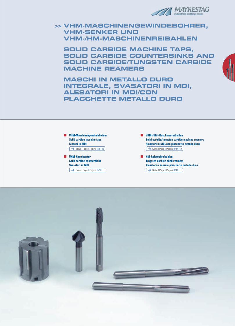
>> VHM-MASCHINENGEWINDEBOHRER,VHM-SENKER UNDVHM-/HM-MASCHINENREIBAHLEN
SOLID CARBIDE MACHINE TAPS,SOLID CARBIDE COUNTERSINKS ANDSOLID CARBIDE/TUNGSTEN CARBIDEMACHINE REAMERS
MASCHI IN METALLO DURO INTEGRALE, SVASATORI IN MDI, ALESATORI IN MDI/CON PLACCHETTE METALLO DURO
� VHM-MaschinengewindebohrerSolid carbide machine tapsMaschi in MDI
� VHM-KegelsenkerSolid carbide countersinksSvasatori in MDI
� VHM-/HM-MaschinenreibahlenSolid carbide/tungsten carbide machine reamersAlesatori in MDI/con placchette metallo duro
� HM-AufsteckreibahlenTungsten carbide shell reamersAlesatori a bussola placchette metallo duro
Seite | Page | Pagina II/6–12 Seite | Page | Pagina II/14–17
Seite | Page | Pagina II/13 Seite | Page | Pagina II/18
II/2
>>>>
DIN 371M
ISO2 6H
C
K40
M 3 – M 10
4775
II/8
��
��
��
��
��
��
��
DIN 371M
ISO2 6H
C
K40
M 3 – M 10
4777
II/8
��
��
��
��
��
��
��
HYPERLOXTM
DIN 371M
ISO2 6H
D
K40
M 6 – M 10
4785
II/6
��
��
��
��
��
��
��
DIN 371M
ISO2 6H
D
K40
M 6 – M 10
4787
II/6
��
��
��
��
��
��
��
HYPERLOXTM
DIN 376M
ISO2 6H
D
K40
M 12 – M 16
4785
II/7
��
��
��
��
��
��
��
DIN 376M
ISO2 6H
D
K40
M 12 – M 16
4787
II/7
��
��
��
��
��
��
��
HYPERLOXTM
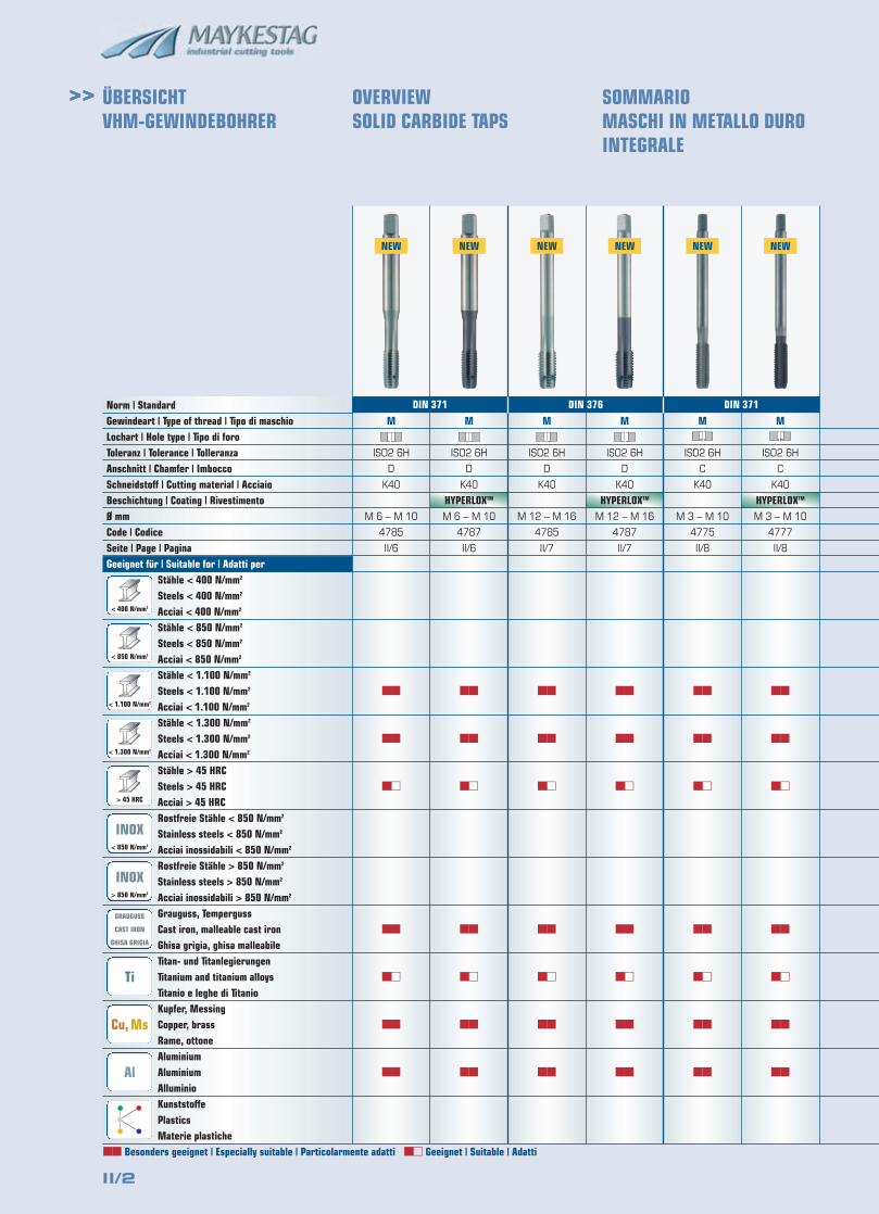
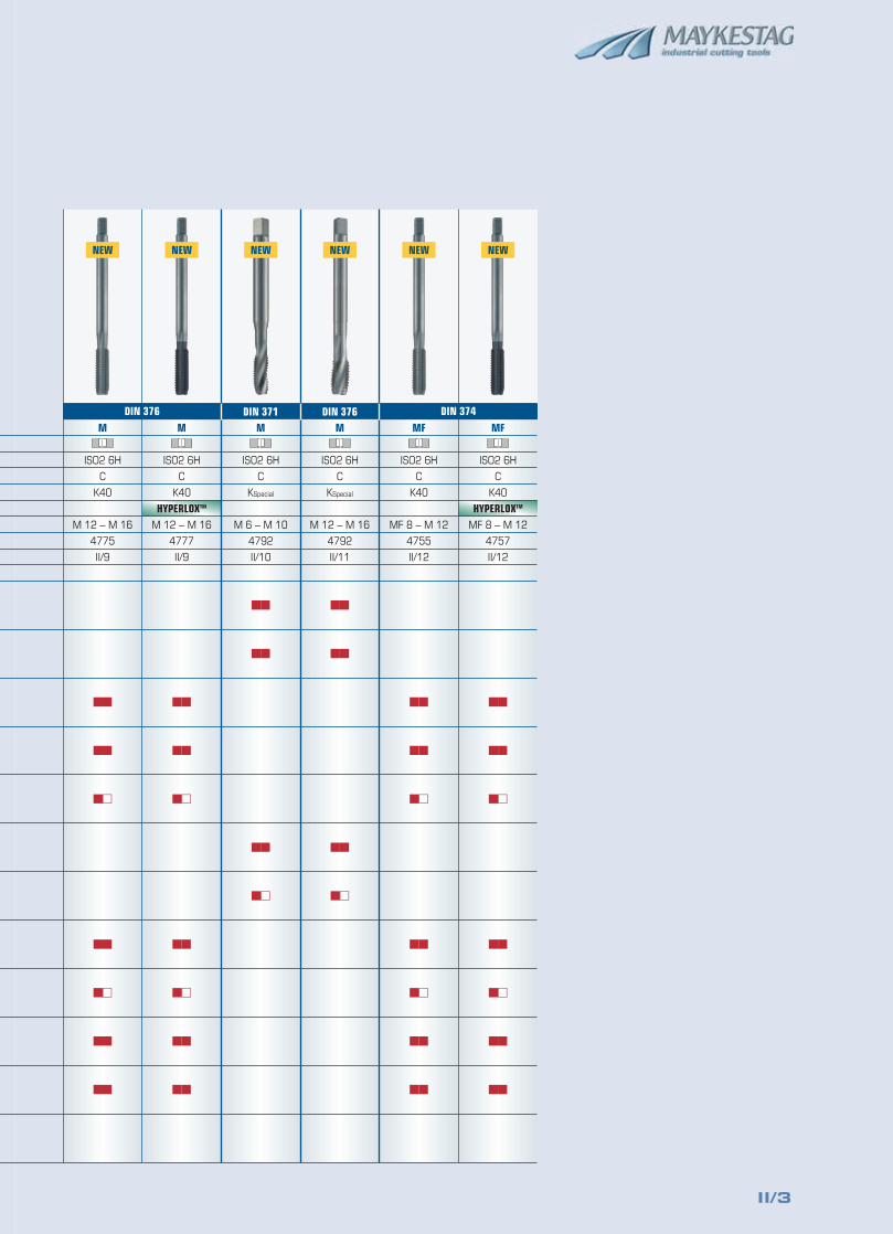
>> ÜBERSICHTVHM-GEWINDEBOHRER
OVERVIEWSOLID CARBIDE TAPS
SOMMARIO MASCHI IN METALLO DURO INTEGRALE
NEW NEW
< 400 N/mm2
> 850 N/mm2
GRAUGUSS
CAST IRON
GHISA GRIGIA
Ti
Cu, Ms
Al
< 850 N/mm2
< 1.100 N/mm2
< 1.300 N/mm2
> 45 HRC
INOX< 850 N/mm2
INOX> 850 N/mm2
�� Besonders geeignet | Especially suitable | Particolarmente adatti �� Geeignet | Suitable | Adatti
Norm | StandardGewindeart | Type of thread | Tipo di maschioLochart | Hole type | Tipo di foroToleranz | Tolerance | TolleranzaAnschnitt | Chamfer | ImboccoSchneidstoff | Cutting material | AcciaioBeschichtung | Coating | RivestimentoØ mmCode | CodiceSeite | Page | PaginaGeeignet für | Suitable for | Adatti per
Stähle < 400 N/mm2
Steels < 400 N/mm2
Acciai < 400 N/mm2
Stähle < 850 N/mm2
Steels < 850 N/mm2
Acciai < 850 N/mm2
Stähle < 1.100 N/mm2
Steels < 1.100 N/mm2
Acciai < 1.100 N/mm2
Stähle < 1.300 N/mm2
Steels < 1.300 N/mm2
Acciai < 1.300 N/mm2
Stähle > 45 HRCSteels > 45 HRCAcciai > 45 HRCRostfreie Stähle < 850 N/mm2
Stainless steels < 850 N/mm2
Acciai inossidabili < 850 N/mm2
Rostfreie Stähle > 850 N/mm2
Stainless steels > 850 N/mm2
Acciai inossidabili > 850 N/mm2
Grauguss, TempergussCast iron, malleable cast ironGhisa grigia, ghisa malleabileTitan- und TitanlegierungenTitanium and titanium alloysTitanio e leghe di TitanioKupfer, MessingCopper, brassRame, ottoneAluminiumAluminiumAlluminioKunststoffePlasticsMaterie plastiche
NEW NEW NEW NEW
DIN 376 DIN 371DIN 371
II/3
DIN 374MF
ISO2 6H
C
K40
MF 8 – M 12
4755
II/12
��
��
��
��
��
��
��
DIN 374MF
ISO2 6H
C
K40
MF 8 – M 12
4757
II/12
��
��
��
��
��
��
��
HYPERLOXTM
DIN 376M
ISO2 6H
C
KSpecial
M 12 – M 16
4792
II/11
��
��
��
��
DIN 371M
ISO2 6H
C
KSpecial
M 6 – M 10
4792
II/10
��
��
��
��
DIN 376M
ISO2 6H
C
K40
M 12 – M 16
4775
II/9
��
��
��
��
��
��
��
DIN 376M
ISO2 6H
C
K40
M 12 – M 16
4777
II/9
��
��
��
��
��
��
��
HYPERLOXTM
NEW NEW NEW NEW NEW NEW
DIN 376 DIN 374
II/4
>>
DIN 335
C | 90˚
K10-F
5,3–31
6407
II/13
��
��
��
��
��
��
��
��
��
��
��
ALUNIT®
DIN 335
C | 90˚
K10-F
5,3–31
6405
II/13
��
��
��
��
��
��
��
��
��
��
��
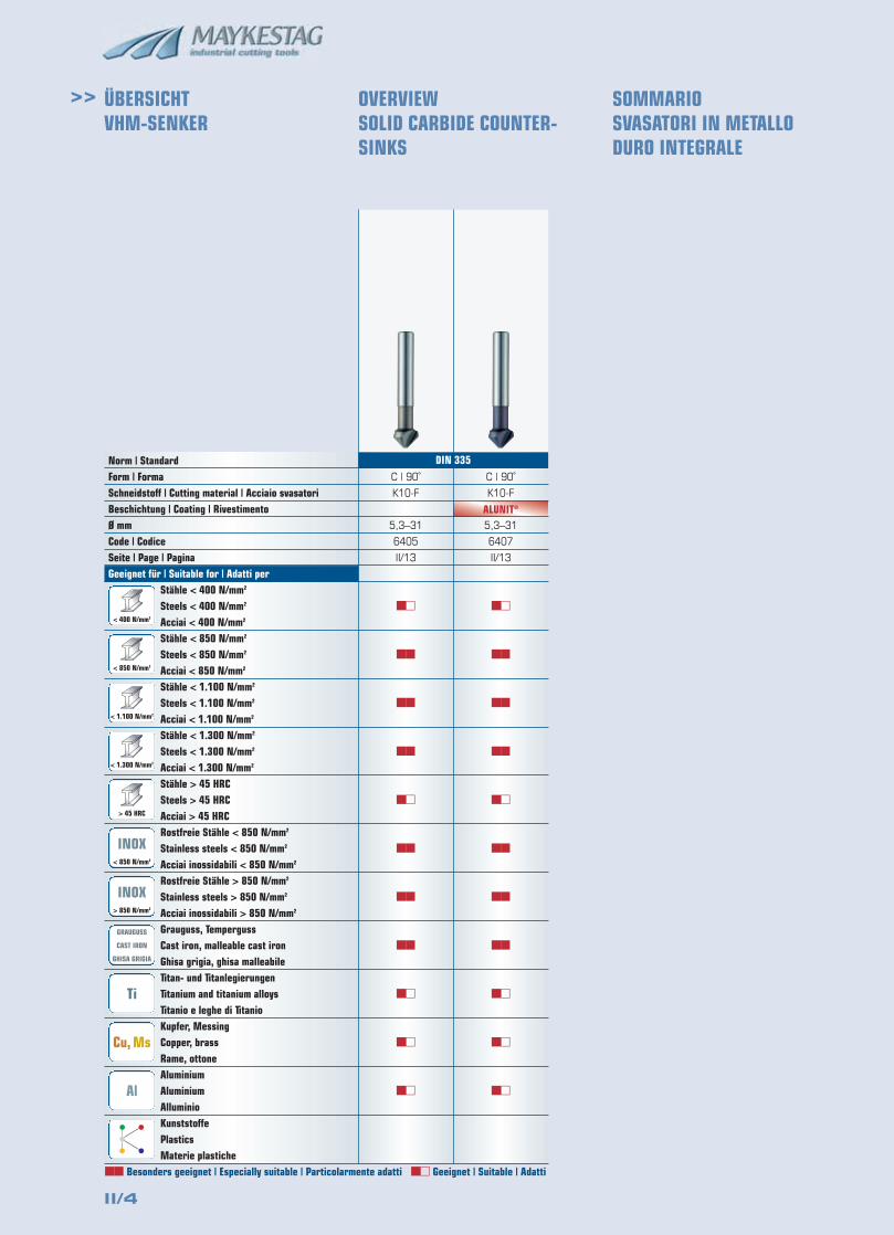
Norm | StandardForm | FormaSchneidstoff | Cutting material | Acciaio svasatoriBeschichtung | Coating | RivestimentoØ mmCode | CodiceSeite | Page | PaginaGeeignet für | Suitable for | Adatti per
Stähle < 400 N/mm2
Steels < 400 N/mm2
Acciai < 400 N/mm2
Stähle < 850 N/mm2
Steels < 850 N/mm2
Acciai < 850 N/mm2
Stähle < 1.100 N/mm2
Steels < 1.100 N/mm2
Acciai < 1.100 N/mm2
Stähle < 1.300 N/mm2
Steels < 1.300 N/mm2
Acciai < 1.300 N/mm2
Stähle > 45 HRCSteels > 45 HRCAcciai > 45 HRCRostfreie Stähle < 850 N/mm2
Stainless steels < 850 N/mm2
Acciai inossidabili < 850 N/mm2
Rostfreie Stähle > 850 N/mm2
Stainless steels > 850 N/mm2
Acciai inossidabili > 850 N/mm2
Grauguss, TempergussCast iron, malleable cast ironGhisa grigia, ghisa malleabileTitan- und TitanlegierungenTitanium and titanium alloysTitanio e leghe di TitanioKupfer, MessingCopper, brassRame, ottoneAluminiumAluminiumAlluminioKunststoffePlasticsMaterie plastiche
ÜBERSICHTVHM-SENKER
OVERVIEWSOLID CARBIDE COUNTER-SINKS
SOMMARIO SVASATORI IN METALLODURO INTEGRALE
< 400 N/mm2
> 850 N/mm2
GRAUGUSS
CAST IRON
GHISA GRIGIA
Ti
Cu, Ms
Al
< 850 N/mm2
< 1.100 N/mm2
< 1.300 N/mm2
> 45 HRC
INOX< 850 N/mm2
INOX> 850 N/mm2
DIN 335
�� Besonders geeignet | Especially suitable | Particolarmente adatti �� Geeignet | Suitable | Adatti
II/5
DIN 217
A
13–27
2520
II/19
DIN 8054
A
K10-F
25–75
5340
II/18
��
��
��
��
��
��
��
��
��
��
WN
B
K10-F
1,4–20
5210
II/16
��
��
��
��
��
��
��
��
��
��
WN
A
K10-F
11–16
5220
II/15
��
��
��
��
��
��
��
��
��
��
WN
A
K10-F
3,0–10
5200
II/14
��
��
��
��
��
��
��
��
��
��
>>
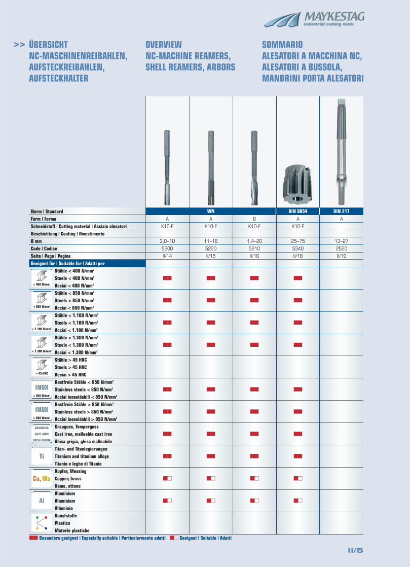
Norm | StandardForm | FormaSchneidstoff | Cutting material | Acciaio alesatoriBeschichtung | Coating | RivestimentoØ mmCode | CodiceSeite | Page | PaginaGeeignet für | Suitable for | Adatti per
Stähle < 400 N/mm2
Steels < 400 N/mm2
Acciai < 400 N/mm2
Stähle < 850 N/mm2
Steels < 850 N/mm2
Acciai < 850 N/mm2
Stähle < 1.100 N/mm2
Steels < 1.100 N/mm2
Acciai < 1.100 N/mm2
Stähle < 1.300 N/mm2
Steels < 1.300 N/mm2
Acciai < 1.300 N/mm2
Stähle > 45 HRCSteels > 45 HRCAcciai > 45 HRCRostfreie Stähle < 850 N/mm2
Stainless steels < 850 N/mm2
Acciai inossidabili < 850 N/mm2
Rostfreie Stähle > 850 N/mm2
Stainless steels > 850 N/mm2
Acciai inossidabili > 850 N/mm2
Grauguss, TempergussCast iron, malleable cast ironGhisa grigia, ghisa malleabileTitan- und TitanlegierungenTitanium and titanium alloysTitanio e leghe di TitanioKupfer, MessingCopper, brassRame, ottoneAluminiumAluminiumAlluminioKunststoffePlasticsMaterie plastiche
ÜBERSICHTNC-MASCHINENREIBAHLEN,AUFSTECKREIBAHLEN,AUFSTECKHALTER
OVERVIEWNC-MACHINE REAMERS, SHELL REAMERS, ARBORS
SOMMARIO ALESATORI A MACCHINA NC,ALESATORI A BUSSOLA, MANDRINI PORTA ALESATORI
< 400 N/mm2
> 850 N/mm2
GRAUGUSS
CAST IRON
GHISA GRIGIA
Ti
Cu, Ms
Al
< 850 N/mm2
< 1.100 N/mm2
< 1.300 N/mm2
> 45 HRC
INOX< 850 N/mm2
INOX> 850 N/mm2
WN
�� Besonders geeignet | Especially suitable | Particolarmente adatti �� Geeignet | Suitable | Adatti
DIN 8054 DIN 217
II/6
>>
Seite | Page | Pagina II/22
SchnittwertempfehlungRecommended cutting conditionsValori di taglio consigliati
blank | bright | lucida HYPERLOXTM
K40
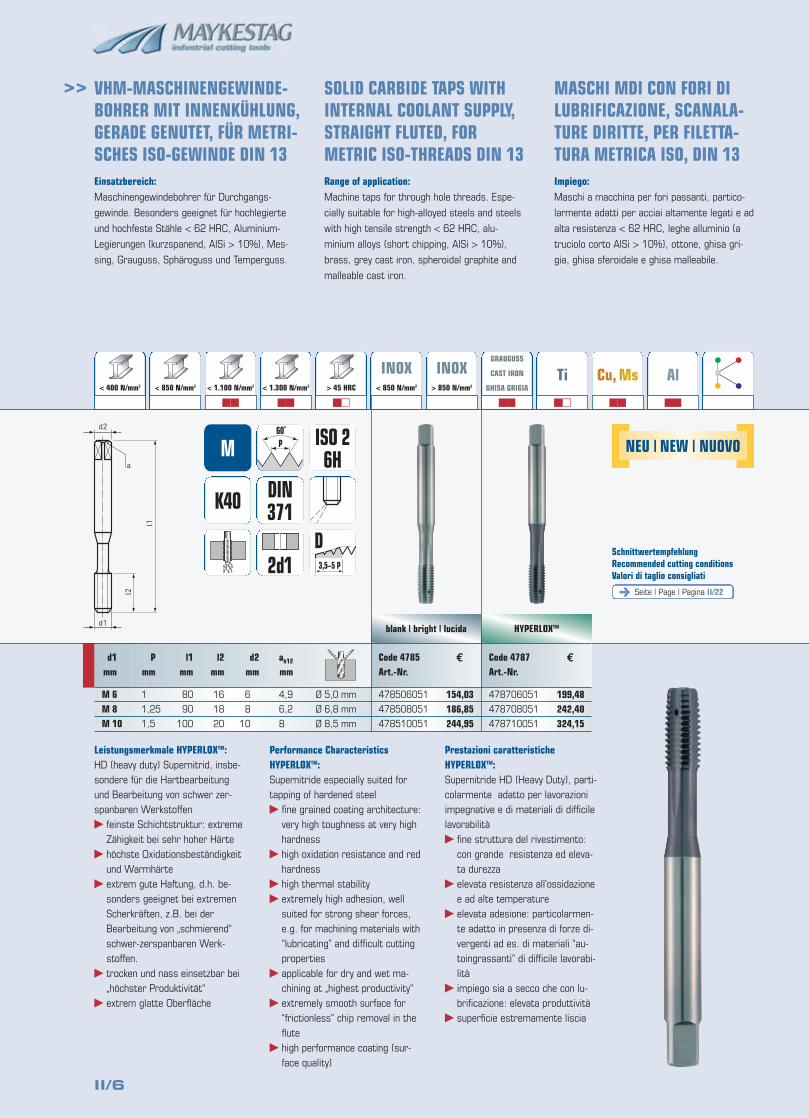
Einsatzbereich:Maschinengewindebohrer für Durchgangs-
gewinde. Besonders geeignet für hochlegierte
und hochfeste Stähle < 62 HRC, Aluminium-
Legierungen (kurzspanend, AlSi > 10%), Mes-
sing, Grauguss, Sphäroguss und Temperguss.
Range of application:Machine taps for through hole threads. Espe-
cially suitable for high-alloyed steels and steels
with high tensile strength < 62 HRC, alu-
minium alloys (short chipping, AlSi > 10%),
brass, grey cast iron, spheroidal graphite and
malleable cast iron.
Impiego:Maschi a macchina per fori passanti, partico-
larmente adatti per acciai altamente legati e ad
alta resistenza < 62 HRC, leghe alluminio (a
truciolo corto AlSi > 10%), ottone, ghisa gri-
gia, ghisa sferoidale e ghisa malleabile.
d1
d2
a
l2
l1
154,03186,85244,95
199,48242,40324,15
VHM-MASCHINENGEWINDE-BOHRER MIT INNENKÜHLUNG,GERADE GENUTET, FÜR METRI-SCHES ISO-GEWINDE DIN 13
SOLID CARBIDE TAPS WITHINTERNAL COOLANT SUPPLY,STRAIGHT FLUTED, FORMETRIC ISO-THREADS DIN 13
MASCHI MDI CON FORI DILUBRIFICAZIONE, SCANALA-TURE DIRITTE, PER FILETTA-TURA METRICA ISO, DIN 13
< 400 N/mm2 > 850 N/mm2
�� �� ��
GRAUGUSS
CAST IRON
GHISA GRIGIA
��
Ti
��
Cu, Ms
��
Al
��
< 850 N/mm2 < 1.100 N/mm2 < 1.300 N/mm2 > 45 HRC
INOX< 850 N/mm2
INOX> 850 N/mm2
3,5–5 P
D
DIN371
M
2d1
Code 4785Art.-Nr.
478506051
478508051
478510051
Code 4787Art.-Nr.
478706051
478708051
478710051
ISO 26H
d1mm
M 6M 8M 10
Pmm
1
1,25
1,5
l1mm
80
90
100
l2mm
16
18
20
d2mm
6
8
10
ah12
mm
4,9
6,2
8
€ €
Leistungsmerkmale HYPERLOXTM:HD (heavy duty) Supernitrid, insbe-sondere für die Hartbearbeitungund Bearbeitung von schwer zer-spanbaren Werkstoffen� feinste Schichtstruktur: extreme
Zähigkeit bei sehr hoher Härte� höchste Oxidationsbeständigkeit
und Warmhärte� extrem gute Haftung, d.h. be-
sonders geeignet bei extremenScherkräften, z.B. bei derBearbeitung von „schmierend“schwer-zerspanbaren Werk-stoffen.
� trocken und nass einsetzbar bei„höchster Produktivität“
� extrem glatte Oberfläche
Performance Characteristics HYPERLOXTM:Supernitride especially suited fortapping of hardened steel� fine grained coating architecture:
very high toughness at very highhardness
� high oxidation resistance and redhardness
� high thermal stability� extremely high adhesion, well
suited for strong shear forces,e.g. for machining materials with“lubricating” and difficult cuttingproperties
� applicable for dry and wet ma-chining at „highest productivity“
� extremely smooth surface for“frictionless” chip removal in theflute
� high performance coating (sur-face quality)
Prestazioni caratteristiche HYPERLOXTM:Supernitride HD (Heavy Duty), parti-colarmente adatto per lavorazioniimpegnative e di materiali di difficilelavorabilità� fine struttura del rivestimento:
con grande resistenza ed eleva-ta durezza
� elevata resistenza all’ossidazionee ad alte temperature
� elevata adesione: particolarmen-te adatto in presenza di forze di-vergenti ad es. di materiali “au-toingrassanti” di difficile lavorabi-lità
� impiego sia a secco che con lu-brificazione: elevata produttività
� superficie estremamente liscia
NEU | NEW | NUOVO
Ø 5,0 mm
Ø 6,8 mm
Ø 8,5 mm
II/7
>>
Seite | Page | Pagina II/22
SchnittwertempfehlungRecommended cutting conditionsValori di taglio consigliati
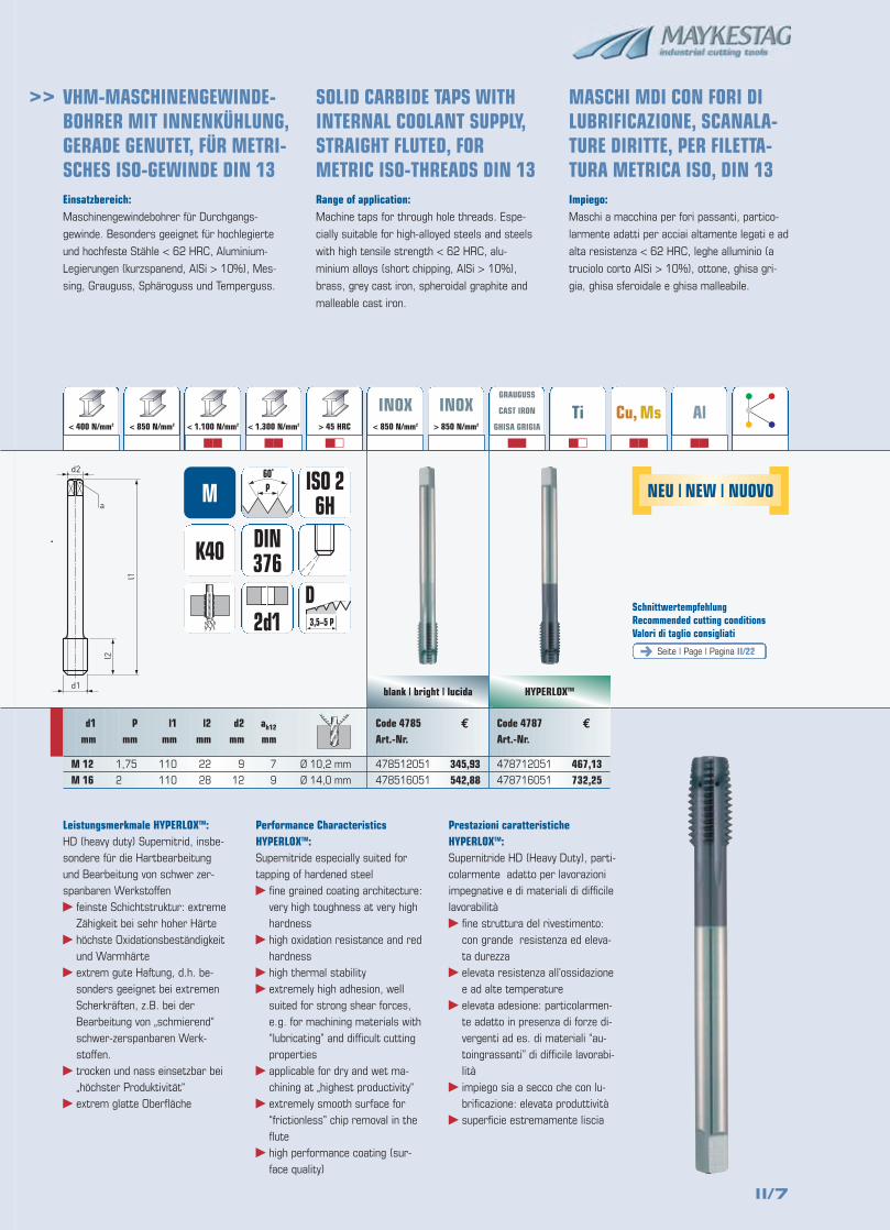
Einsatzbereich:Maschinengewindebohrer für Durchgangs-
gewinde. Besonders geeignet für hochlegierte
und hochfeste Stähle < 62 HRC, Aluminium-
Legierungen (kurzspanend, AlSi > 10%), Mes-
sing, Grauguss, Sphäroguss und Temperguss.
Range of application:Machine taps for through hole threads. Espe-
cially suitable for high-alloyed steels and steels
with high tensile strength < 62 HRC, alu-
minium alloys (short chipping, AlSi > 10%),
brass, grey cast iron, spheroidal graphite and
malleable cast iron.
Impiego:Maschi a macchina per fori passanti, partico-
larmente adatti per acciai altamente legati e ad
alta resistenza < 62 HRC, leghe alluminio (a
truciolo corto AlSi > 10%), ottone, ghisa gri-
gia, ghisa sferoidale e ghisa malleabile.
blank | bright | lucidad1
d2
a
l2
l1
345,93542,88
K40
3,5–5 P
D
DIN376
M
2d1
Code 4785Art.-Nr.
478512051
478516051
€
ISO 26H
d1mm
M 12M 16
Pmm
1,75
2
l1mm
110
110
l2mm
22
28
d2mm
9
12
ah12
mm
7
9
VHM-MASCHINENGEWINDE-BOHRER MIT INNENKÜHLUNG,GERADE GENUTET, FÜR METRI-SCHES ISO-GEWINDE DIN 13
SOLID CARBIDE TAPS WITHINTERNAL COOLANT SUPPLY,STRAIGHT FLUTED, FORMETRIC ISO-THREADS DIN 13
MASCHI MDI CON FORI DILUBRIFICAZIONE, SCANALA-TURE DIRITTE, PER FILETTA-TURA METRICA ISO, DIN 13
< 400 N/mm2 > 850 N/mm2
�� �� ��
GRAUGUSS
CAST IRON
GHISA GRIGIA
��
Ti
��
Cu, Ms
��
Al
��
< 850 N/mm2 < 1.100 N/mm2 < 1.300 N/mm2 > 45 HRC
INOX< 850 N/mm2
INOX> 850 N/mm2
HYPERLOXTM
467,13732,25
Code 4787Art.-Nr.
478712051
478716051
€
Leistungsmerkmale HYPERLOXTM:HD (heavy duty) Supernitrid, insbe-sondere für die Hartbearbeitungund Bearbeitung von schwer zer-spanbaren Werkstoffen� feinste Schichtstruktur: extreme
Zähigkeit bei sehr hoher Härte� höchste Oxidationsbeständigkeit
und Warmhärte� extrem gute Haftung, d.h. be-
sonders geeignet bei extremenScherkräften, z.B. bei derBearbeitung von „schmierend“schwer-zerspanbaren Werk-stoffen.
� trocken und nass einsetzbar bei„höchster Produktivität“
� extrem glatte Oberfläche
Performance Characteristics HYPERLOXTM:Supernitride especially suited fortapping of hardened steel� fine grained coating architecture:
very high toughness at very highhardness
� high oxidation resistance and redhardness
� high thermal stability� extremely high adhesion, well
suited for strong shear forces,e.g. for machining materials with“lubricating” and difficult cuttingproperties
� applicable for dry and wet ma-chining at „highest productivity“
� extremely smooth surface for“frictionless” chip removal in theflute
� high performance coating (sur-face quality)
Prestazioni caratteristiche HYPERLOXTM:Supernitride HD (Heavy Duty), parti-colarmente adatto per lavorazioniimpegnative e di materiali di difficilelavorabilità� fine struttura del rivestimento:
con grande resistenza ed eleva-ta durezza
� elevata resistenza all’ossidazionee ad alte temperature
� elevata adesione: particolarmen-te adatto in presenza di forze di-vergenti ad es. di materiali “au-toingrassanti” di difficile lavorabi-lità
� impiego sia a secco che con lu-brificazione: elevata produttività
� superficie estremamente liscia
NEU | NEW | NUOVO
Ø 10,2 mm
Ø 14,0 mm
II/8
>>
Seite | Page | Pagina II/22
SchnittwertempfehlungRecommended cutting conditionsValori di taglio consigliati
blank | bright | lucida HYPERLOXTM
K40
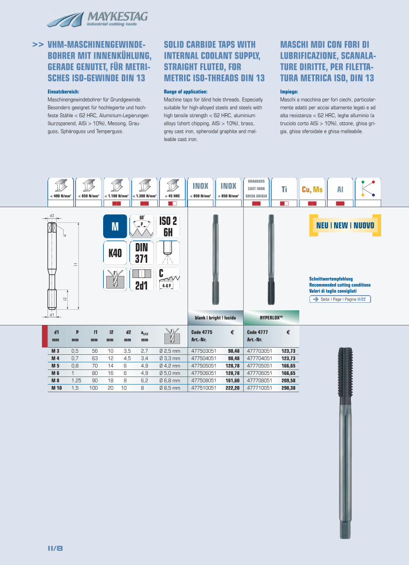
Einsatzbereich:Maschinengewindebohrer für Grundgewinde.
Besonders geeignet für hochlegierte und hoch-
feste Stähle < 62 HRC, Aluminium-Legierungen
(kurzspanend, AlSi > 10%), Messing, Grau-
guss, Sphäroguss und Temperguss.
Range of application:Machine taps for blind hole threads. Especially
suitable for high-alloyed steels and steels with
high tensile strength < 62 HRC, aluminium
alloys (short chipping, AlSi > 10%), brass,
grey cast iron, spheroidal graphite and mal-
leable cast iron.
Impiego:Maschi a macchina per fori ciechi, particolar-
mente adatti per acciai altamente legati e ad
alta resistenza < 62 HRC, leghe alluminio (a
truciolo corto AlSi > 10%), ottone, ghisa gri-
gia, ghisa sferoidale e ghisa malleabile.
d1
d2
a
l2
l1
98,4898,48
128,78128,78161,60222,20
123,73123,73166,65166,65209,58290,38
< 400 N/mm2 > 850 N/mm2
�� �� ��
GRAUGUSS
CAST IRON
GHISA GRIGIA
��
Ti
��
Cu, Ms
��
Al
��
< 850 N/mm2 < 1.100 N/mm2 < 1.300 N/mm2 > 45 HRC
INOX< 850 N/mm2
INOX> 850 N/mm2
4–6 P
C
DIN371
M
2d1
Code 4775Art.-Nr.
477503051
477504051
477505051
477506051
477508051
477510051
Code 4777Art.-Nr.
477703051
477704051
477705051
477706051
477708051
477710051
ISO 26H
d1mm
M 3M 4M 5M 6M 8M 10
Pmm
0,5
0,7
0,8
1
1,25
1,5
l1mm
56
63
70
80
90
100
l2mm
10
12
14
16
18
20
d2mm
3,5
4,5
6
6
8
10
ah12
mm
2,7
3,4
4,9
4,9
6,2
8
€ €
VHM-MASCHINENGEWINDE-BOHRER MIT INNENKÜHLUNG,GERADE GENUTET, FÜR METRI-SCHES ISO-GEWINDE DIN 13
SOLID CARBIDE TAPS WITHINTERNAL COOLANT SUPPLY,STRAIGHT FLUTED, FORMETRIC ISO-THREADS DIN 13
MASCHI MDI CON FORI DILUBRIFICAZIONE, SCANALA-TURE DIRITTE, PER FILETTA-TURA METRICA ISO, DIN 13
NEU | NEW | NUOVO
Ø 2,5 mm
Ø 3,3 mm
Ø 4,2 mm
Ø 5,0 mm
Ø 6,8 mm
Ø 8,5 mm
II/9
>>
Seite | Page | Pagina II/22
SchnittwertempfehlungRecommended cutting conditionsValori di taglio consigliati
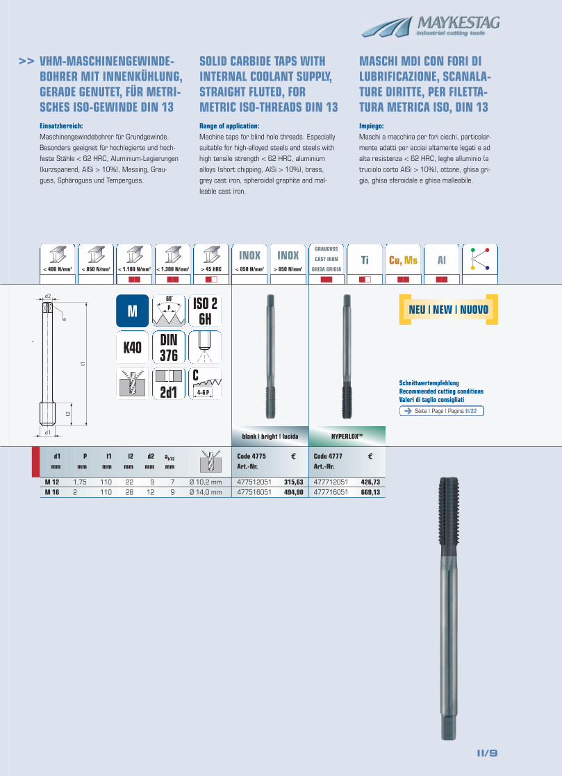
Einsatzbereich:Maschinengewindebohrer für Grundgewinde.
Besonders geeignet für hochlegierte und hoch-
feste Stähle < 62 HRC, Aluminium-Legierungen
(kurzspanend, AlSi > 10%), Messing, Grau-
guss, Sphäroguss und Temperguss.
Range of application:Machine taps for blind hole threads. Especially
suitable for high-alloyed steels and steels with
high tensile strength < 62 HRC, aluminium
alloys (short chipping, AlSi > 10%), brass,
grey cast iron, spheroidal graphite and mal-
leable cast iron.
Impiego:Maschi a macchina per fori ciechi, particolar-
mente adatti per acciai altamente legati e ad
alta resistenza < 62 HRC, leghe alluminio (a
truciolo corto AlSi > 10%), ottone, ghisa gri-
gia, ghisa sferoidale e ghisa malleabile.
blank | bright | lucidad1
d2
a
l2
l1
315,63494,90
K40
4–6 P
C
DIN376
M
2d1
Code 4775Art.-Nr.
477512051
477516051
€
ISO 26H
d1mm
M 12M 16
Pmm
1,75
2
l1mm
110
110
l2mm
22
28
d2mm
9
12
ah12
mm
7
9
< 400 N/mm2 > 850 N/mm2
�� �� ��
GRAUGUSS
CAST IRON
GHISA GRIGIA
��
Ti
��
Cu, Ms
��
Al
��
< 850 N/mm2 < 1.100 N/mm2 < 1.300 N/mm2 > 45 HRC
INOX< 850 N/mm2
INOX> 850 N/mm2
HYPERLOXTM
426,73669,13
Code 4777Art.-Nr.
477712051
477716051
€
VHM-MASCHINENGEWINDE-BOHRER MIT INNENKÜHLUNG,GERADE GENUTET, FÜR METRI-SCHES ISO-GEWINDE DIN 13
SOLID CARBIDE TAPS WITHINTERNAL COOLANT SUPPLY,STRAIGHT FLUTED, FORMETRIC ISO-THREADS DIN 13
MASCHI MDI CON FORI DILUBRIFICAZIONE, SCANALA-TURE DIRITTE, PER FILETTA-TURA METRICA ISO, DIN 13
NEU | NEW | NUOVO
Ø 10,2 mm
Ø 14,0 mm
II/10
>>
Seite | Page | Pagina II/22
SchnittwertempfehlungRecommended cutting conditionsValori di taglio consigliati
blank | bright | lucida
KSpecial
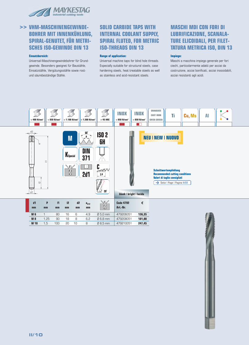
Einsatzbereich:Universal-Maschinengewindebohrer für Grund-
gewinde. Besonders geeignet für Baustähle,
Einsatzstähle, Vergütungsstähle sowie rost-
und säurebeständige Stähle.
Range of application:Universal machine taps for blind hole threads.
Especially suitable for structural steels, case
hardening steels, heat treatable steels as well
as stainless and acid-resistant steels.
Impiego:Maschi a macchina impiego generale per fori
ciechi, particolarmente adatti per acciai da
costruzione, acciai bonificati, acciai inossidabili,
acciai resistenti agli acidi.
d1
d2
a
l2
l1
136,35181,80247,45
< 400 N/mm2 > 850 N/mm2
�� �� �� ��
GRAUGUSS
CAST IRON
GHISA GRIGIATi Cu, Ms Al
< 850 N/mm2 < 1.100 N/mm2 < 1.300 N/mm2 > 45 HRC
INOX< 850 N/mm2
INOX> 850 N/mm2
DIN371
M
Code 4792Art.-Nr.
479206051
479208051
479210051
€
ISO 26H
d1mm
M 6M 8M 10
Pmm
1
1,25
1,5
l1mm
80
90
100
l2mm
16
18
20
d2mm
6
8
10
ah12
mm
4,9
6,2
8
VHM-MASCHINENGEWINDE-BOHRER MIT INNENKÜHLUNG,SPIRAL-GENUTET, FÜR METRI-SCHES ISO-GEWINDE DIN 13
SOLID CARBIDE TAPS WITHINTERNAL COOLANT SUPPLY,SPIRAL FLUTED, FOR METRICISO-THREADS DIN 13
MASCHI MDI CON FORI DILUBRIFICAZIONE, SCANALA-TURE ELICOIDALI, PER FILET-TATURA METRICA ISO, DIN 13
3 P
C
20˚
2d1
NEU | NEW | NUOVO
Ø 5,0 mm
Ø 6,8 mm
Ø 8,5 mm
II/11
>>
Seite | Page | Pagina II/22
SchnittwertempfehlungRecommended cutting conditionsValori di taglio consigliati
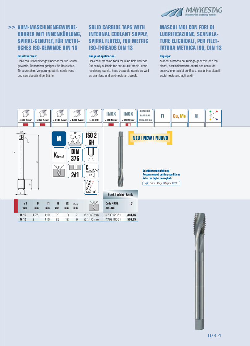
Einsatzbereich:Universal-Maschinengewindebohrer für Grund-
gewinde. Besonders geeignet für Baustähle,
Einsatzstähle, Vergütungsstähle sowie rost-
und säurebeständige Stähle.
Range of application:Universal machine taps for blind hole threads.
Especially suitable for structural steels, case
hardening steels, heat treatable steels as well
as stainless and acid-resistant steels.
Impiego:Maschi a macchina impiego generale per fori
ciechi, particolarmente adatti per acciai da
costruzione, acciai bonificati, acciai inossidabili,
acciai resistenti agli acidi.
blank | bright | lucidad1
d2
a
l2
l1
348,45570,65
KSpecialDIN376
M
Code 4792Art.-Nr.
479212051
479216051
€
ISO 26H
d1mm
M 12M 16
Pmm
1,75
2
l1mm
110
110
l2mm
22
28
d2mm
9
12
ah12
mm
7
9
2d1
20˚
3 P
C
< 400 N/mm2 > 850 N/mm2
�� �� �� ��
GRAUGUSS
CAST IRON
GHISA GRIGIATi Cu, Ms Al
< 850 N/mm2 < 1.100 N/mm2 < 1.300 N/mm2 > 45 HRC
INOX< 850 N/mm2
INOX> 850 N/mm2
VHM-MASCHINENGEWINDE-BOHRER MIT INNENKÜHLUNG,SPIRAL-GENUTET, FÜR METRI-SCHES ISO-GEWINDE DIN 13
SOLID CARBIDE TAPS WITHINTERNAL COOLANT SUPPLY,SPIRAL FLUTED, FOR METRICISO-THREADS DIN 13
MASCHI MDI CON FORI DILUBRIFICAZIONE, SCANALA-TURE ELICOIDALI, PER FILET-TATURA METRICA ISO, DIN 13
NEU | NEW | NUOVO
Ø 10,2 mm
Ø 14,0 mm
II/12
>>
blank | bright | lucida HYPERLOXTM
K40
d1
d2
a
l2
l1
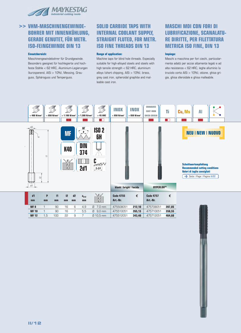
212,10265,13343,40
287,85358,55464,60
VHM-MASCHINENGEWINDE-BOHRER MIT INNENKÜHLUNG,GERADE GENUTET, FÜR METR.ISO-FEINGEWINDE DIN 13
SOLID CARBIDE TAPS WITH INTERNAL COOLANT SUPPLY,STRAIGHT FLUTED, FOR METR.ISO FINE THREADS DIN 13
MASCHI MDI CON FORI DI LUBRIFICAZIONE, SCANALATU-RE DIRITTE, PER FILETTATURAMETRICA ISO FINE, DIN 13
< 400 N/mm2 > 850 N/mm2
�� �� ��
GRAUGUSS
CAST IRON
GHISA GRIGIA
��
Ti
��
Cu, Ms
��
Al
��
< 850 N/mm2 < 1.100 N/mm2 < 1.300 N/mm2 > 45 HRC
INOX< 850 N/mm2
INOX> 850 N/mm2
2–3 P
C
DIN374
MF
2d1
Code 4755Art.-Nr.
475508051
475510051
475512051
Code 4757Art.-Nr.
475708051
475710051
475712051
ISO 26H
d1mm
MF 8MF 10MF 12
Pmm
1
1
1,5
l1mm
90
90
100
l2mm
16
16
22
d2mm
6
7
9
ah12
mm
4,9
5,5
7
€ €
Einsatzbereich:Maschinengewindebohrer für Grundgewinde.
Besonders geeignet für hochlegierte und hoch-
feste Stähle < 62 HRC, Aluminium-Legierungen
(kurzspanend, AlSi > 10%), Messing, Grau-
guss, Sphäroguss und Temperguss.
Range of application:Machine taps for blind hole threads. Especially
suitable for high-alloyed steels and steels with
high tensile strength < 62 HRC, aluminium
alloys (short chipping, AlSi > 10%), brass,
grey cast iron, spheroidal graphite and mal-
leable cast iron.
Impiego:Maschi a macchina per fori ciechi, particolar-
mente adatti per acciai altamente legati e ad
alta resistenza < 62 HRC, leghe alluminio (a
truciolo corto AlSi > 10%), ottone, ghisa gri-
gia, ghisa sferoidale e ghisa malleabile.
Seite | Page | Pagina II/22
SchnittwertempfehlungRecommended cutting conditionsValori di taglio consigliati
NEU | NEW | NUOVO
Ø 7,0 mm
Ø 9,0 mm
Ø 10,5 mm
II/13
>>
ALUNIT®
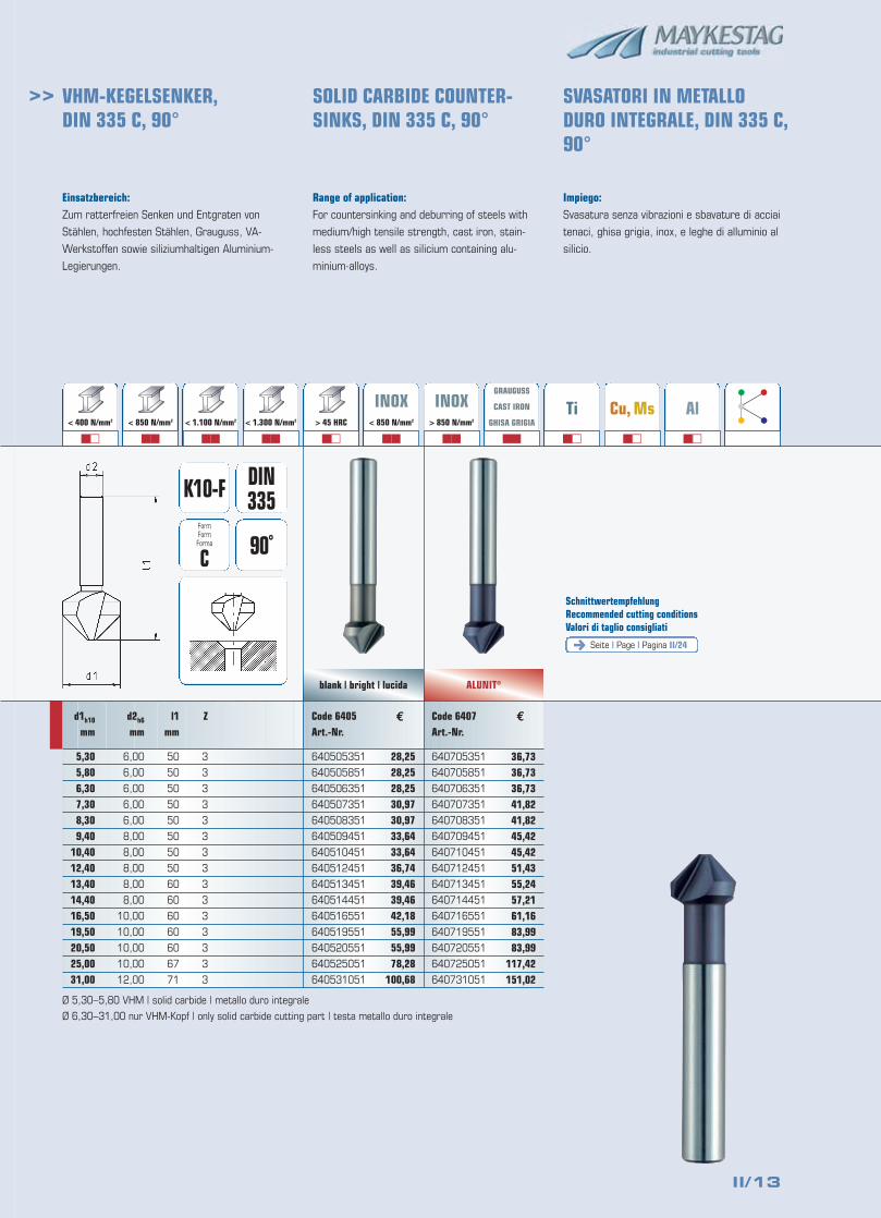
Einsatzbereich:Zum ratterfreien Senken und Entgraten von
Stählen, hochfesten Stählen, Grauguss, VA-
Werkstoffen sowie siliziumhaltigen Aluminium-
Legierungen.
Range of application:For countersinking and deburring of steels with
medium/high tensile strength, cast iron, stain-
less steels as well as silicium containing alu-
minium-alloys.
Impiego:Svasatura senza vibrazioni e sbavature di acciai
tenaci, ghisa grigia, inox, e leghe di alluminio al
silicio.
Seite | Page | Pagina II/24
SchnittwertempfehlungRecommended cutting conditionsValori di taglio consigliati
blank | bright | lucida
36,7336,7336,7341,8241,8245,4245,4251,4355,2457,2161,1683,9983,99
117,42151,02
Code 6405Art.-Nr.
640505351
640505851
640506351
640507351
640508351
640509451
640510451
640512451
640513451
640514451
640516551
640519551
640520551
640525051
640531051
€Code 6407Art.-Nr.
640705351
640705851
640706351
640707351
640708351
640709451
640710451
640712451
640713451
640714451
640716551
640719551
640720551
640725051
640731051
VHM-KEGELSENKER, DIN 335 C, 90°
SOLID CARBIDE COUNTER-SINKS, DIN 335 C, 90°
SVASATORI IN METALLO DURO INTEGRALE, DIN 335 C,90°
d1h10
mm
5,305,806,307,308,309,40
10,4012,4013,4014,4016,5019,5020,5025,0031,00
d2h6
mm
6,00
6,00
6,00
6,00
6,00
8,00
8,00
8,00
8,00
8,00
10,00
10,00
10,00
10,00
12,00
l1mm
50
50
50
50
50
50
50
50
60
60
60
60
60
67
71
Z
3
3
3
3
3
3
3
3
3
3
3
3
3
3
3
FormFormForma
C
K10-F DIN335
90˚
< 400 N/mm2 > 850 N/mm2
�� �� �� �� �� �� ��
GRAUGUSS
CAST IRON
GHISA GRIGIA
��
Ti
��
Cu, Ms
��
Al
��
< 850 N/mm2 < 1.100 N/mm2 < 1.300 N/mm2 > 45 HRC
INOX< 850 N/mm2
INOX> 850 N/mm2
€
28,2528,2528,2530,9730,9733,6433,6436,7439,4639,4642,1855,9955,9978,28
100,68
Ø 5,30–5,80 VHM | solid carbide | metallo duro integrale
Ø 6,30–31,00 nur VHM-Kopf | only solid carbide cutting part | testa metallo duro integrale
II/14
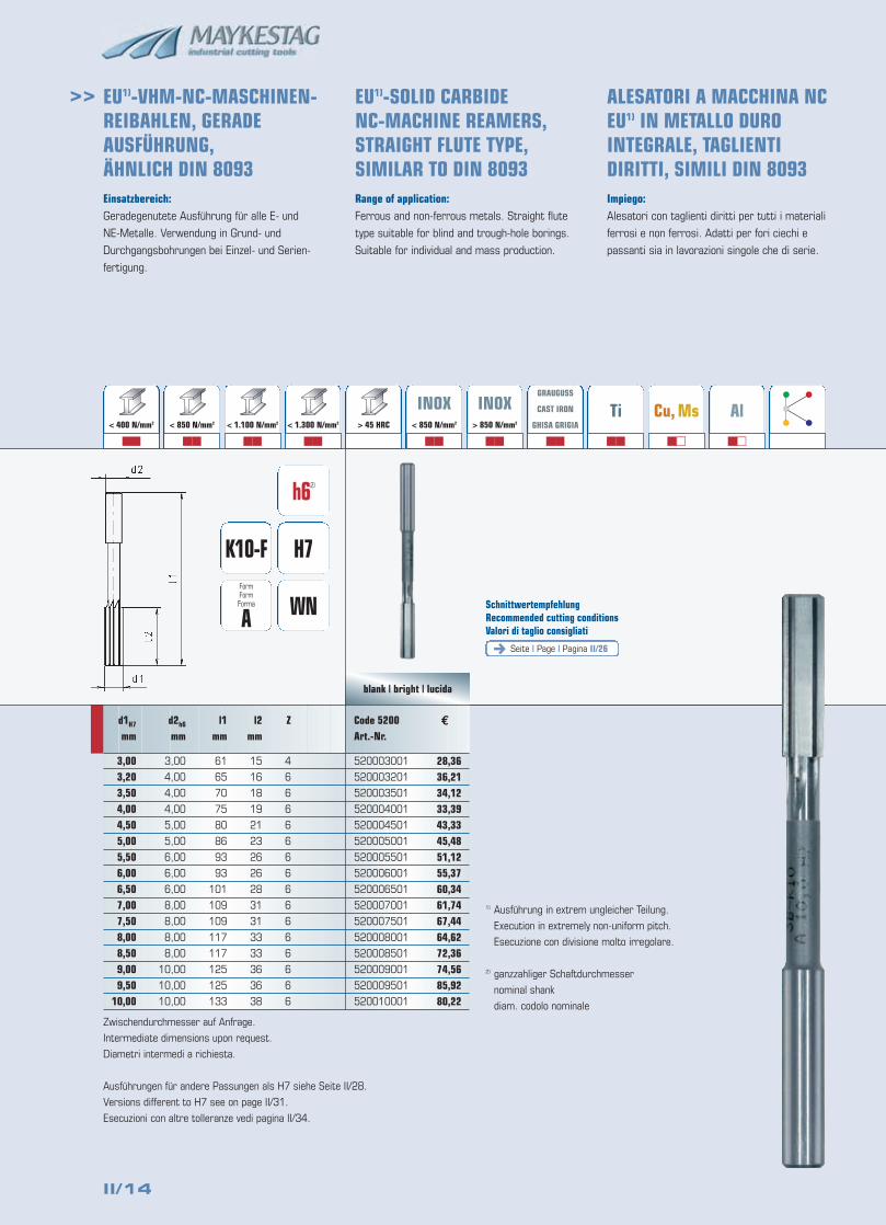
>> EU1)-VHM-NC-MASCHINEN-REIBAHLEN, GERADE AUSFÜHRUNG, ÄHNLICH DIN 8093
EU1)-SOLID CARBIDE NC-MACHINE REAMERS,STRAIGHT FLUTE TYPE,SIMILAR TO DIN 8093
ALESATORI A MACCHINA NCEU1) IN METALLO DUROINTEGRALE, TAGLIENTIDIRITTI, SIMILI DIN 8093
Einsatzbereich:Geradegenutete Ausführung für alle E- und
NE-Metalle. Verwendung in Grund- und
Durchgangsbohrungen bei Einzel- und Serien-
fertigung.
Range of application:Ferrous and non-ferrous metals. Straight flute
type suitable for blind and trough-hole borings.
Suitable for individual and mass production.
Impiego:Alesatori con taglienti diritti per tutti i materiali
ferrosi e non ferrosi. Adatti per fori ciechi e
passanti sia in lavorazioni singole che di serie.
Zwischendurchmesser auf Anfrage.
Intermediate dimensions upon request.
Diametri intermedi a richiesta.
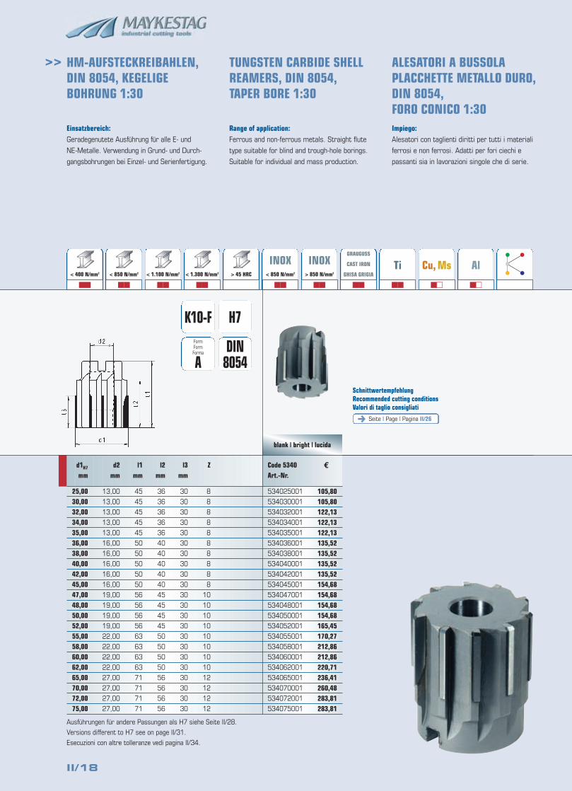
Ausführungen für andere Passungen als H7 siehe Seite II/28.
Versions different to H7 see on page II/31.
Esecuzioni con altre tolleranze vedi pagina II/34.
€
H7
h62)
K10-F
WNFormFormForma
ASeite | Page | Pagina II/26
SchnittwertempfehlungRecommended cutting conditionsValori di taglio consigliati
blank | bright | lucida
< 400 N/mm2 > 850 N/mm2
�� �� �� �� �� ��
GRAUGUSS
CAST IRON
GHISA GRIGIA
��
Ti
��
Cu, Ms
��
Al
��
< 850 N/mm2 < 1.100 N/mm2 < 1.300 N/mm2 > 45 HRC
INOX< 850 N/mm2
INOX> 850 N/mm2
28,3636,2134,1233,3943,3345,4851,1255,3760,3461,7467,4464,6272,3674,5685,9280,22
Z
4
6
6
6
6
6
6
6
6
6
6
6
6
6
6
6
l2mm
15
16
18
19
21
23
26
26
28
31
31
33
33
36
36
38
l1mm
61
65
70
75
80
86
93
93
101
109
109
117
117
125
125
133
d2h6
mm
3,00
4,00
4,00
4,00
5,00
5,00
6,00
6,00
6,00
8,00
8,00
8,00
8,00
10,00
10,00
10,00
d1H7
mm
3,003,203,504,004,505,005,506,006,507,007,508,008,509,009,50
10,00
Code 5200Art.-Nr.
520003001
520003201
520003501
520004001
520004501
520005001
520005501
520006001
520006501
520007001
520007501
520008001
520008501
520009001
520009501
520010001
1) Ausführung in extrem ungleicher Teilung.
Execution in extremely non-uniform pitch.
Esecuzione con divisione molto irregolare.
2) ganzzahliger Schaftdurchmesser
nominal shank
diam. codolo nominale
II/15
>>
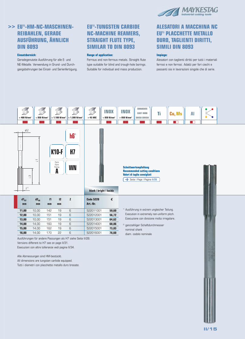
Einsatzbereich:Geradegenutete Ausführung für alle E- und
NE-Metalle. Verwendung in Grund- und Durch-
gangsbohrungen bei Einzel- und Serienfertigung.
Range of application:Ferrous and non-ferrous metals. Straight flute
type suitable for blind and trough-hole borings.
Suitable for individual and mass production.
Impiego:Alesatori con taglienti diritti per tutti i materiali
ferrosi e non ferrosi. Adatti per fori ciechi e
passanti sia in lavorazioni singole che di serie.
Ausführungen für andere Passungen als H7 siehe Seite II/28.
Versions different to H7 see on page II/31.
Esecuzioni con altre tolleranze vedi pagina II/34.
Alle Abmessungen sind HM-bestückt.
All dimensions are tungsten carbide equipped.
Tutti i diametri con placchette metallo duro brasate.
€
H7
h62)
K10-F
WNFormFormForma
ASeite | Page | Pagina II/26
SchnittwertempfehlungRecommended cutting conditionsValori di taglio consigliati
blank | bright | lucida
< 400 N/mm2 > 850 N/mm2
�� �� �� �� �� ��
GRAUGUSS
CAST IRON
GHISA GRIGIA
��
Ti
��
Cu, Ms
��
Al
��
< 850 N/mm2 < 1.100 N/mm2 < 1.300 N/mm2 > 45 HRC
INOX< 850 N/mm2
INOX> 850 N/mm2
59,6056,7264,6268,8673,8376,60
Z
6
6
6
6
6
6
l2mm
19
19
19
19
19
22
l1mm
142
151
151
160
162
170
d2h6
mm
10,00
10,00
10,00
14,00
14,00
14,00
d1H7
mm
11,0012,0013,0014,0015,0016,00
Code 5220Art.-Nr.
522011001
522012001
522013001
522014001
522015001
522016001
EU1)-HM-NC-MASCHINEN-REIBAHLEN, GERADEAUSFÜHRUNG, ÄHNLICHDIN 8093
EU1)-TUNGSTEN CARBIDENC-MACHINE REAMERS,STRAIGHT FLUTE TYPE,SIMILAR TO DIN 8093
ALESATORI A MACCHINA NCEU1) PLACCHETTE METALLODURO, TAGLIENTI DIRITTI,SIMILI DIN 8093
1) Ausführung in extrem ungleicher Teilung.
Execution in extremely non-uniform pitch.
Esecuzione con divisione molto irregolare.
2) ganzzahliger Schaftdurchmesser
nominal shank
diam. codolo nominale
II/16
>>
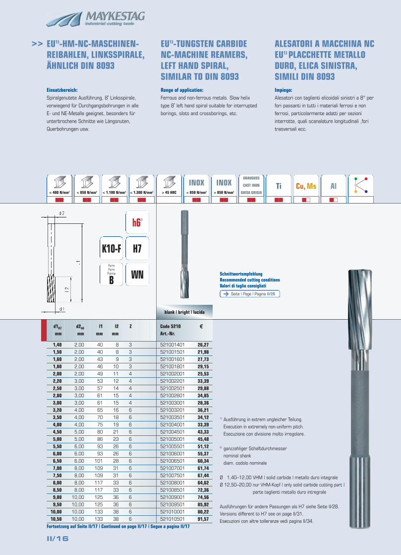
Einsatzbereich:Spiralgenutete Ausführung, 8˚ Linksspirale,
vorwiegend für Durchgangsbohrungen in alle
E- und NE-Metalle geeignet, besonders für
unterbrochene Schnitte wie Längsnuten,
Querbohrungen usw.
Range of application:Ferrous and non-ferrous metals. Slow helix
type 8˚ left hand spiral suitable for interrupted
borings, slots and crossborings, etc.
Impiego:Alesatori con taglienti elicoidali sinistri a 8° per
fori passanti in tutti i materiali ferrosi e non
ferrosi, particolarmente adatti per sezioni
interrotte, quali scanalature longitudinali ,fori
trasversali ecc.
1) Ausführung in extrem ungleicher Teilung.
Execution in extremely non-uniform pitch.
Esecuzione con divisione molto irregolare.
2) ganzzahliger Schaftdurchmesser
nominal shank
diam. codolo nominale
Ø 1,40–12,00 VHM | solid carbide | metallo duro integrale
Ø 12,50–20,00 nur VHM-Kopf | only solid carbide cutting part |
parte taglienti metallo duro intregrale
Ausführungen für andere Passungen als H7 siehe Seite II/28.
Versions different to H7 see on page II/31.
Esecuzioni con altre tolleranze vedi pagina II/34.
€
H7
h62)
K10-F
WNFormFormForma
BSeite | Page | Pagina II/26
SchnittwertempfehlungRecommended cutting conditionsValori di taglio consigliati
blank | bright | lucida
< 400 N/mm2 > 850 N/mm2
�� �� �� �� �� ��
GRAUGUSS
CAST IRON
GHISA GRIGIA
��
Ti
��
Cu, Ms
��
Al
��
< 850 N/mm2 < 1.100 N/mm2 < 1.300 N/mm2 > 45 HRC
INOX< 850 N/mm2
INOX> 850 N/mm2
26,2721,9827,7329,1525,5333,3929,8834,8528,3636,2134,1233,3943,3345,4851,1255,3760,3461,7467,4464,6272,3674,5685,9280,2291,57
Z
3
3
3
3
4
4
4
4
4
6
6
6
6
6
6
6
6
6
6
6
6
6
6
6
6
l2mm
8
8
9
10
11
12
14
15
15
16
18
19
21
23
26
26
28
31
31
33
33
36
36
38
38
l1mm
40
40
43
46
49
53
57
61
61
65
70
75
80
86
93
93
101
109
109
117
117
125
125
133
133
d2h6
mm
2,00
2,00
2,00
2,00
2,00
3,00
3,00
3,00
3,00
4,00
4,00
4,00
5,00
5,00
6,00
6,00
6,00
8,00
8,00
8,00
8,00
10,00
10,00
10,00
10,00
d1H7
mm
1,401,501,601,802,002,202,502,803,003,203,504,004,505,005,506,006,507,007,508,008,509,009,50
10,0010,50
Code 5210Art.-Nr.
521001401
521001501
521001601
521001801
521002001
521002201
521002501
521002801
521003001
521003201
521003501
521004001
521004501
521005001
521005501
521006001
521006501
521007001
521007501
521008001
521008501
521009001
521009501
521010001
521010501
Fortsetzung auf Seite II/17 | Continued on page II/17 | Segue a pagina II/17
EU1)-HM-NC-MASCHINEN-REIBAHLEN, LINKSSPIRALE,ÄHNLICH DIN 8093
EU1)-TUNGSTEN CARBIDENC-MACHINE REAMERS,LEFT HAND SPIRAL,SIMILAR TO DIN 8093
ALESATORI A MACCHINA NCEU1) PLACCHETTE METALLODURO, ELICA SINISTRA,SIMILI DIN 8093
II/17
>>
€
blank | bright | lucida
93,71110,0996,49
109,37109,37122,13137,72149,76176,76193,82210,14225,01
Z
6
6
6
6
8
8
8
8
6
6
6
6
l2mm
41
41
41
44
44
47
50
52
54
56
58
60
l1mm
142
142
142
151
151
160
162
170
175
182
189
195
d2h6
mm
10,00
10,00
10,00
10,00
10,00
14,00
14,00
14,00
14,00
14,00
16,00
16,00
d1H7
mm
11,0011,5012,0012,5013,0014,0015,0016,0017,0018,0019,0020,00
Code 5210Art.-Nr.
521011001
521011501
521012001
521012501
521013001
521014001
521015001
521016001
521017001
521018001
521019001
521020001
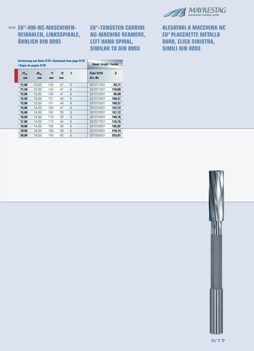
Fortsetzung von Seite II/16 | Continued from page II/16| Segue da pagina II/16
EU1)-HM-NC-MASCHINEN-REIBAHLEN, LINKSSPIRALE,ÄHNLICH DIN 8093
EU1)-TUNGSTEN CARBIDENC-MACHINE REAMERS,LEFT HAND SPIRAL,SIMILAR TO DIN 8093
ALESATORI A MACCHINA NCEU1) PLACCHETTE METALLODURO, ELICA SINISTRA,SIMILI DIN 8093
II/18
>>
Einsatzbereich:Geradegenutete Ausführung für alle E- und
NE-Metalle. Verwendung in Grund- und Durch-
gangsbohrungen bei Einzel- und Serienfertigung.
Range of application:Ferrous and non-ferrous metals. Straight flute
type suitable for blind and trough-hole borings.
Suitable for individual and mass production.
Impiego:Alesatori con taglienti diritti per tutti i materiali
ferrosi e non ferrosi. Adatti per fori ciechi e
passanti sia in lavorazioni singole che di serie.
€
H7K10-F
DIN8054
FormFormForma
A
Seite | Page | Pagina II/26
SchnittwertempfehlungRecommended cutting conditionsValori di taglio consigliati
blank | bright | lucida
< 400 N/mm2 > 850 N/mm2
�� �� �� �� �� ��
GRAUGUSS
CAST IRON
GHISA GRIGIA
��
Ti
��
Cu, Ms
��
Al
��
< 850 N/mm2 < 1.100 N/mm2 < 1.300 N/mm2 > 45 HRC
INOX< 850 N/mm2
INOX> 850 N/mm2
105,80105,80122,13122,13122,13135,52135,52135,52135,52154,68154,68154,68154,68165,45170,27212,86212,86220,71236,41260,48283,81283,81
Z
8
8
8
8
8
8
8
8
8
8
10
10
10
10
10
10
10
10
12
12
12
12
l2mm
36
36
36
36
36
40
40
40
40
40
45
45
45
45
50
50
50
50
56
56
56
56
l3mm
30
30
30
30
30
30
30
30
30
30
30
30
30
30
30
30
30
30
30
30
30
30
l1mm
45
45
45
45
45
50
50
50
50
50
56
56
56
56
63
63
63
63
71
71
71
71
d2mm
13,00
13,00
13,00
13,00
13,00
16,00
16,00
16,00
16,00
16,00
19,00
19,00
19,00
19,00
22,00
22,00
22,00
22,00
27,00
27,00
27,00
27,00
d1H7
mm
25,0030,0032,0034,0035,0036,0038,0040,0042,0045,0047,0048,0050,0052,0055,0058,0060,0062,0065,0070,0072,0075,00
Code 5340Art.-Nr.
534025001
534030001
534032001
534034001
534035001
534036001
534038001
534040001
534042001
534045001
534047001
534048001
534050001
534052001
534055001
534058001
534060001
534062001
534065001
534070001
534072001
534075001
HM-AUFSTECKREIBAHLEN,DIN 8054, KEGELIGEBOHRUNG 1:30
TUNGSTEN CARBIDE SHELLREAMERS, DIN 8054,TAPER BORE 1:30
ALESATORI A BUSSOLA PLACCHETTE METALLO DURO,DIN 8054, FORO CONICO 1:30
Ausführungen für andere Passungen als H7 siehe Seite II/28.
Versions different to H7 see on page II/31.
Esecuzioni con altre tolleranze vedi pagina II/34.
II/19
>>
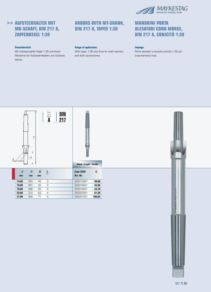
Einsatzbereich:Mit Aufsteckzapfen Kegel 1:30 und fester
Mitnahme für Aufsteckreibahlen und Aufsteck-
bohrer.
Range of application:With taper 1:30 and drive for shell reamers
and shell counterbores.
Impiego:Porta alesatori a bussola conicità 1:30 con
trascinamento fisso.
€
DIN217
FormFormForma
A
blank | bright | lucida
40,8645,6854,1067,29
100,93
3
3
4
4
4
l2mm
45
50
56
63
71
l1mm
250
261
298
312
359
dmm
13,0016,0019,0022,0027,00
Code 2520Art.-Nr.
252013001
252016001
252019001
252022001
252027001
AUFSTECKHALTER MIT MK-SCHAFT, DIN 217 A,ZAPFENKEGEL 1:30
ARBORS WITH MT-SHANK,DIN 217 A, TAPER 1:30
MANDRINI PORTAALESATORI CONO MORSE,DIN 217 A, CONICITÀ 1:30

II/20
II/21
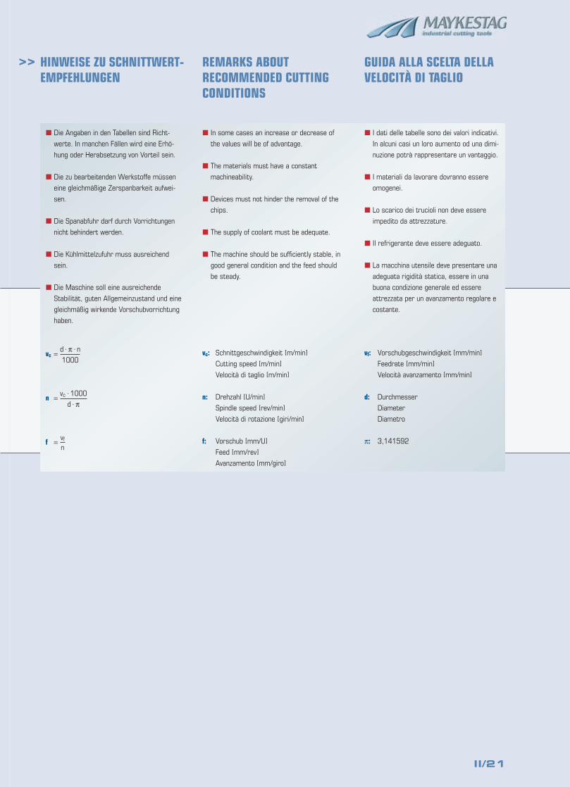
>> HINWEISE ZU SCHNITTWERT-EMPFEHLUNGEN
REMARKS ABOUTRECOMMENDED CUTTINGCONDITIONS
GUIDA ALLA SCELTA DELLAVELOCITÀ DI TAGLIO
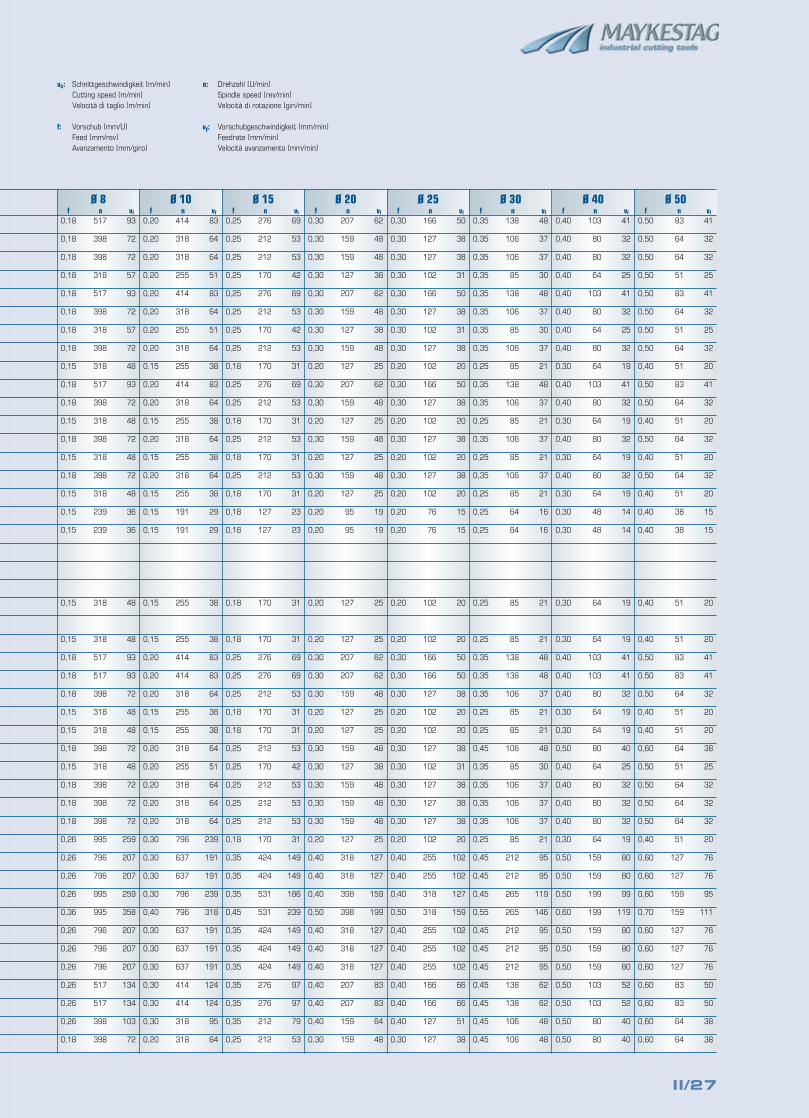
vc: Schnittgeschwindigkeit [m/min]
Cutting speed [m/min]
Velocità di taglio [m/min]
n: Drehzahl [U/min]
Spindle speed [rev/min]
Velocità di rotazione [giri/min]
f: Vorschub [mm/U]
Feed [mm/rev]
Avanzamento [mm/giro]
vf: Vorschubgeschwindigkeit [mm/min]
Feedrate [mm/min]
Velocità avanzamento [mm/min]
d: Durchmesser
Diameter
Diametro
π: 3,141592
d · π · nvc =
1000
vc · 1000n =
d · π
vff =n
� Die Angaben in den Tabellen sind Richt-
werte. In manchen Fällen wird eine Erhö-
hung oder Herabsetzung von Vorteil sein.
� Die zu bearbeitenden Werkstoffe müssen
eine gleichmäßige Zerspanbarkeit aufwei-
sen.
� Die Spanabfuhr darf durch Vorrichtungen
nicht behindert werden.
� Die Kühlmittelzufuhr muss ausreichend
sein.
� Die Maschine soll eine ausreichende
Stabilität, guten Allgemeinzustand und eine
gleichmäßig wirkende Vorschubvorrichtung
haben.
� In some cases an increase or decrease of
the values will be of advantage.
� The materials must have a constant
machineability.
� Devices must not hinder the removal of the
chips.
� The supply of coolant must be adequate.
� The machine should be sufficiently stable, in
good general condition and the feed should
be steady.
� I dati delle tabelle sono dei valori indicativi.
In alcuni casi un loro aumento od una dimi-
nuzione potrà rappresentare un vantaggio.
� I materiali da lavorare dovranno essere
omogenei.
� Lo scarico dei trucioli non deve essere
impedito da attrezzature.
� Il refrigerante deve essere adeguato.
� La macchina utensile deve presentare una
adeguata rigidità statica, essere in una
buona condizione generale ed essere
attrezzata per un avanzamento regolare e
costante.
II/22
>>
St 37-2
St 50-2, St 60-2
9 S 20, 9 S MnPb 28,35 S 2060 S 20
C 22, C 35,Ck 35C 45, Ck 45
36 Mn 5, Ck 60
38 Cr 2, 28 Cr 4
25 CrMo 4, 34 CrNiMo 6, 42 CrMo 4C 15, Ck 15
15 CrNi 6, 13 Cr 2,16 MnCr 520 MnCr 5, 15 CrMo 5
34 CrAlMo 5, 34 CrAl 6,34 CrAlS 531 CrMoV 9
C 45 W, 100 Cr 6
40 CrMnMoS 8-6, X 36 CrMo 17, X 100 CrMoV 51X 210 Cr 12, X 40 CrMoV 51, X 155 CrVMo 12 1S 18-1-2-5, S 18-1-2-10, S 6-5-2Hardox 400
38 Si 7, 55 Cr 3, 50 CrV 4X 14 CrMoS 17,X 8 CrNiS 18-9X 6 Cr 13, X 2 CrNiMoSi 19 5 3, X 12 CrNi 25-21X 12 CrS 13, X 20 Cr 13,X 12 CrMnNi 18 8 5X 17 CrNi 16-2, X 12 CrNi 177, NiCr 20 Co 18 TiNimonic 105, Hastelloy C22, Inconell 718GG 15, GG 20
GG 25, GG 30, GG 40GGG-40, GGG-60,GTW-40GGG-80, GTS-65
Ti 1, TiCu 2, TiAl 5 Sn 2,5G-AlMg 5, AlMg 3,AlMg 2 Mn 0,8MgAl 3 Zn, MgMn 2,MgAl 8 ZnSE-Cu, CuSn 6
CuZn 39 Pb 2,CuZn 39 Pb 3CuZn 20, CuZn 33,CuZn 37 Pb 0,5G-CuSn 7 Zn, G-CuPb 5 Sn
CuNi 18 Zn 19 Pb 1
CuAl 5, CuAl 9 Mn 2
CuBe 2
1.0037
1.0050, 1.0060
1.0711, 1.0718,1.07261.0728
1.0402, 1.0501,1.11801.0503, 1.1191
1.1167, 1.1221
1.7003, 1.7030
1.7218, 1.6582,1.72251.0401, 1.1141
1.5919, 1.7012,1.71311.7147, 1.7262
1.8507, 1.8504,1.85061.8519
1.1730, 1.2067
1.2312, 1.2316,1.23631.2080, 1.2344,1.23791.3255, 1.3265,1.3243
1.5023, 1.7176,1.81591.4104, 1.4305
1.4000, 1.4417,1.48451.4005, 1.4021,1.43711.4057, 1.4310,2.46322.4634, 2.4602,2.46680.6015, 0.6020
0.6025, 0.6030,0.60400.7040, 0.7060,0.80400.7080, 0.8165
3.7025, 3.7124,3.71143.3561, 3.3535,3.35273.5314, 3.5200,3.58122.0070, 2.1020
2.0380, 2.0401
2.0250, 2.0280,2.03322.1090, 2.1170
2.0790
2.0916, 2.0960
2.1247
< 500 N/mm2
500–850 N/mm2
< 850 N/mm2
850–1000 N/mm2
< 700 N/mm2
700–850 N/mm2
850–1000 N/mm2
850–1000 N/mm2
1000–1200 N/mm2
< 750 N/mm2
< 1000 N/mm2
1000–1200 N/mm2
< 1000 N/mm2
1000–1200 N/mm2
< 850 N/mm2
850–1100 N/mm2
1100–1400 N/mm2
850–1200 N/mm2
1350 N/mm2
< 1200 N/mm2
< 700 N/mm2
< 700 N/mm2
< 850 N/mm2
< 1100 N/mm2
< 1200 N/mm2
< 180 HB
> 180 HB
> 180 HB
> 260 HB
< 850 N/mm2
< 530 N/mm2
< 280 N/mm2
< 350 N/mm2
< 600 N/mm2
< 600 N/mm2
< 600 N/mm2
650–850 N/mm2
< 850 N/mm2
850–1200 N/mm2
Werkstoffbezeichnung MaterialMateriale
vc
50–70
50–70
50–70
40–60
50–70
50–70
40–60
40–60
40–60
50–70
50–70
40–60
40–60
40–60
50–70
50–70
30–50
30–50
30–40
30–50
50–70
50–70
50–70
40–60
40–60
50–70
50–70
50–70
50–70
30–50
50–70
50–70
50–70
50–70
50–70
50–70
50–70
50–70
50–70
O/E
O/E
O/E
O/E
O/E
O/E
O/E
O/E
O/E
O/E
O/E
O/E
O/E
O/E
O
O
O
O/E
O
O
O
O
O
O
O
T/E
T/E
T/E
T/E
O
O/E
T
E/O
E
E
E
E
E
E
Kühlung2)
Coolant2)
Lubrificazione2)
DIN-Bezeichnung1)
DIN-description1)
Norma DIN1)
Werkstoff-Nr.1)
Material nr.1)
Nr. materiale1)
ZugfestigkeitTensile strengthResistenza
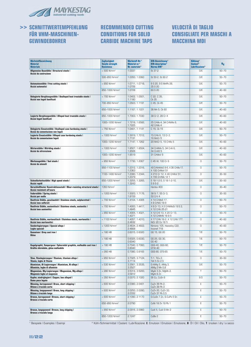
SCHNITTWERTEMPFEHLUNGFÜR VHM-MASCHINEN-GEWINDEBOHRER
RECOMMENDED CUTTINGCONDITIONS FOR SOLIDCARBIDE MACHINE TAPS
VELOCITÀ DI TAGLIOCONSIGLIATE PER MASCHI AMACCHINA MDI
1) Beispiele | Examples | Esempi 2) Kühl-/Schmiermittel | Coolant | Lubrificazione: E: Emulsion | Emulsion | Emulsione, O: Öl | Oil | Olio, T: trocken | dry | a secco
Allgemeine Baustähle | Structural steels | Acciai da costruzione
Automatenstähle | Free cutting steels | Acciai automatici
Unlegierte Vergütungsstähle | Unalloyed heat treatable steels | Acciai non legati bonificati
Legierte Vergütungsstähle | Alloyed heat treatable steels | Acciai legati bonificati
Unlegierte Einsatzstähle | Unalloyed case hardening steels | Acciai da cementazione non legatiLegierte Einsatzstähle | Alloyed case hardening steels | Acciai da cementazione legati
Nitrierstähle | Nitriding steels | Acciai da nitrurazione
Werkzeugstähle | Tool steels | Acciai da utensili
Schnellarbeitsstähle | High speed steels | Acciai rapidiVerschleißfester Konstruktionsstahl | Wear-resisting structural steels | Acciai resistenti all’usura Federstähle | Spring steels | Acciai per molleRostfreie Stähle, geschwefelt | Stainless steels, sulphuretted | Acciai inox solforatiRostfreie Stähle, austenitisch | Stainless steels, austenitic | Acciai inox austenitici
Rostfreie Stähle, martensitisch | Stainless steels, martensitic | Acciai inox martensiticiSonderlegierungen | Special alloys | Leghe specialiGusseisen | Grey cast iron | Ghisa
Kugelgraphit, Temperguss | Spheroidal graphite, malleable cast iron | Grafite sferoidale, ghisa malleabile
Titan, Titanlegierungen | Titanium, titanium alloys | Titanio, leghe di TitanioAluminium, Al-Legierungen | Aluminium, Al-alloys | Alluminio, leghe di alluminioMagnesium, Mg-Legierungen | Magnesium, Mg-alloys | Magnesio leghe al magnesioKupfer, niedriglegiert | Copper, low alloyed | Rame poco legatoMessing, kurzspanend | Brass, short chipping | Ottone a truciolo cortoMessing, langspanend | Brass, long chipping | Ottone a truciolo lungoBronze, kurzspanend | Bronze, short chipping | Bronzo a truciolo corto
Bronze, langspanend | Bronze, long chipping | Bronzo a truciolo lungo
II/23
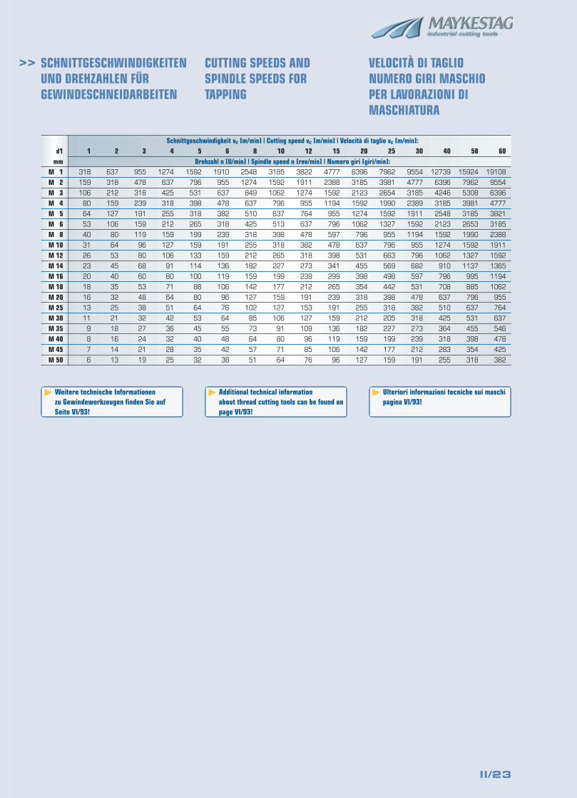
>> SCHNITTGESCHWINDIGKEITENUND DREHZAHLEN FÜRGEWINDESCHNEIDARBEITEN
CUTTING SPEEDS ANDSPINDLE SPEEDS FORTAPPING
VELOCITÀ DI TAGLIO NUMERO GIRI MASCHIO PER LAVORAZIONI DIMASCHIATURA
Drehzahl n [U/min] | Spindle speed n [rev/min] | Numero giri [giri/min]:
Schnittgeschwindigkeit vc [m/min] | Cutting speed vc [m/min] | Velocità di taglio vc [m/min]:1 2 3 4 5 6 8 10 12 15 20 25 30 40 50 60d1
mmM 1 318 637 955 1274 1592 1910 2548 3185 3822 4777 6396 7962 9554 12739 15924 19108
M 2 159 318 478 637 796 955 1274 1592 1911 2388 3185 3981 4777 6396 7962 9554
M 3 106 212 318 425 531 637 849 1062 1274 1592 2123 2654 3185 4246 5308 6396
M 4 80 159 239 318 398 478 637 796 955 1194 1592 1990 2389 3185 3981 4777
M 5 64 127 191 255 318 382 510 637 764 955 1274 1592 1911 2548 3185 3821
M 6 53 106 159 212 265 318 425 513 637 796 1062 1327 1592 2123 2653 3185
M 8 40 80 119 159 199 239 318 398 478 597 796 955 1194 1592 1990 2388
M 10 31 64 96 127 159 191 255 318 382 478 637 796 955 1274 1592 1911
M 12 26 53 80 106 133 159 212 265 318 398 531 663 796 1062 1327 1592
M 14 23 45 68 91 114 136 182 227 273 341 455 569 682 910 1137 1365
M 16 20 40 60 80 100 119 159 199 239 299 398 498 597 796 995 1194
M 18 18 35 53 71 88 106 142 177 212 265 354 442 531 708 885 1062
M 20 16 32 48 64 80 96 127 159 191 239 318 398 478 637 796 955
M 25 13 25 38 51 64 76 102 127 153 191 255 318 382 510 637 764
M 30 11 21 32 42 53 64 85 106 127 159 212 205 318 425 531 637
M 35 9 18 27 36 45 55 73 91 109 136 182 227 273 364 455 546
M 40 8 16 24 32 40 48 64 80 96 119 159 199 239 318 398 478
M 45 7 14 21 28 35 42 57 71 85 106 142 177 212 283 354 425
M 50 6 13 19 25 32 38 51 64 76 96 127 159 191 255 318 382
� Weitere technische Informationen zu Gewindewerkzeugen finden Sie auf Seite VI/93!
� Additional technical information about thread cutting tools can be found onpage VI/93!
� Ulteriori informazioni tecniche sui maschipagina VI/93!
II/24
>>
Werkstoffbezeichnung MaterialMateriale
Ø 4f n vf
0,07 5173 372
0,06 4775 286
0,06 4775 286
0,04 3979 167
0,06 4775 286
0,06 4775 286
0,04 3581 150
0,04 3581 150
0,03 1432 43
0,06 4775 286
0,04 3979 167
0,03 1432 43
0,04 3979 167
0,03 1432 43
0,04 3979 167
0,03 1432 43
0,09 637 57
0,03 1432 43
0,09 637 57
0,09 637 57
0,09 637 57
0,09 637 57
0,03 1432 43
0,04 1273 53
0,04 1273 53
0,04 1273 53
0,04 1273 53
0,09 637 57
0,08 3581 290
0,06 1989 119
0,06 1989 119
0,06 1989 119
0,04 1273 53
0,10 12732 1299
0,08 5968 483
0,08 3581 290
0,10 12732 1299
0,08 5968 483
0,10 11539 1177
0,10 7162 731
0,10 11539 1177
0,10 11539 1177
0,10 7162 731
0,10 7162 731
0,08 3581 290
vcmin. Start max.
E
E
E
E
E
E
E
E
E
E
E
E
E
E
E
E
E
E
E
E
E
E
E
E
E
E
E
E
T
T
E
E
E
E
E
E
E
E
E
E
E
E
E
E
T
Kühlung2)
Coolant2)
Lubrificaz.2)
St 37-2
St 50-2, St 60-2
9 S 20, 9 S MnPb 28,35 S 2060 S 20
C 22, C 35,Ck 35C 45, Ck 45
36 Mn 5, Ck 60
38 Cr 2, 28 Cr 4
25 CrMo 4, 34 CrNiMo 6,42 CrMo 4C 15, Ck 15
15 CrNi 6, 13 Cr 2,16 MnCr 520 MnCr 5, 15 CrMo 5
34 CrAlMo 5, 34 CrAl 6,34 CrAlS 531 CrMoV 9
C 45 W, 100 Cr 6
40 CrMnMoS 8-6, X 36CrMo 17, X 100 CrMoV 51X 210 Cr 12, X 40 CrMoV51, X 155 CrVMo 12 1S 18-1-2-5, S 18-1-2-10, S 6-5-2
Hardox 400
Hardox 500
38 Si 7, 55 Cr 3, 50 CrV 4X 14 CrMoS 17,X 8 CrNiS 18-9X 6 Cr 13, X 2 CrNiMoSi 195 3, X 12 CrNi 25-21X 12 CrS 13, X 20 Cr 13,X 12 CrMnNi 18 8 5X 17 CrNi 16-2, X 12 CrNi177, NiCr 20 Co 18 TiNimonic 105, Hastelloy C22,Inconell 718GG 15, GG 20
GG 25, GG 30, GG 40GGG-40, GGG-60,GTW-40GGG-80, GTS-65
Ti 1, TiCu 2, TiAl 5 Sn 2,5G-AlMg 5, AlMg 3,AlMg 2 Mn 0,8G-AlSi 6 Cu 4, G-AlSi 5 Mg,G-AlSi 10 MgG-AlSi 12,G-AlSi 12 CuMgAl 3 Zn, MgMn 2,MgAl 8 ZnSE-Cu, CuSn 6
CuZn 39 Pb 2,CuZn 39 Pb 3CuZn 20, CuZn 33,CuZn 37 Pb 0,5G-CuSn 7 Zn, G-CuPb 5 Sn
CuNi 18 Zn 19 Pb 1
CuAl 5, CuAl 9 Mn 2
CuBe 2
DIN-Bezeichnung1)
DIN-description1)
Norma DIN1)
Werkstoff-Nr.1)
Material nr.1)
Nr. materiale1)
1.0037
1.0050, 1.0060
1.0711, 1.0718,1.07261.0728
1.0402, 1.0501,1.11801.0503, 1.1191
1.1167, 1.1221
1.7003, 1.7030
1.7218, 1.6582,1.72251.0401, 1.1141
1.5919, 1.7012,1.71311.7147, 1.7262
1.8507, 1.8504,1.85061.8519
1.1730, 1.2067
1.2312, 1.2316,1.23631.2080, 1.2344,1.23791.3255, 1.3265,1.3243
1.5023, 1.7176,1.81591.4104, 1.4305
1.4000, 1.4417,1.48451.4005, 1.4021,1.43711.4057, 1.4310,2.46322.4634, 2.4602,2.46680.6015, 0.6020
0.6025, 0.6030,0.60400.7040, 0.7060,0.80400.7080, 0.8165
3.7025, 3.7124,3.71143.3561, 3.3535,3.35273.2151, 3.2341,3.2381.013.2581.013.25833.5314, 3.5200,3.58122.0070, 2.1020
2.0380, 2.0401
2.0250, 2.0280,2.03322.1090, 2.1170
2.0790
2.0916, 2.0960
2.1247
ZugfestigkeitTensile strengthResistenza< 500 N/mm2
500–850 N/mm2
< 850 N/mm2
850–1000 N/mm2
< 700 N/mm2
700–850 N/mm2
850–1000 N/mm2
850–1000 N/mm2
1000–1200 N/mm2
< 750 N/mm2
< 1000 N/mm2
1000–1200 N/mm2
< 1000 N/mm2
1000–1200 N/mm2
< 850 N/mm2
850–1100 N/mm2
1100–1400 N/mm2
850–1200 N/mm2
48–55 HRC
55–60 HRC
60–67 HRC
1350 N/mm2
1800 N/mm2
< 1200 N/mm2
< 700 N/mm2
< 700 N/mm2
< 850 N/mm2
< 1100 N/mm2
< 1200 N/mm2
< 180 HB
> 180 HB
> 180 HB
> 260 HB
< 850 N/mm2
< 530 N/mm2
< 600 N/mm2
< 600 N/mm2
< 280 N/mm2
< 350 N/mm2
< 600 N/mm2
< 600 N/mm2
< 600 N/mm2
650–850 N/mm2
< 850 N/mm2
850–1200 N/mm2
Allgemeine Baustähle | Structural steels | Acciai da costruzione
Automatenstähle | Free cutting steels | Acciai automatici
Unlegierte Vergütungsstähle | Unalloyed heat treatable steels | Acciai non legati bonificati
Legierte Vergütungsstähle | Alloyed heat treatable steels | Acciai legati bonificati
Unlegierte Einsatzstähle | Unalloyed case hardening steels | Acciai da cementazione non legatiLegierte Einsatzstähle | Alloyed case hardening steels | Acciai da cementazione legati
Nitrierstähle | Nitriding steels | Acciai da nitrurazione
Werkzeugstähle | Tool steels | Acciai da utensili
Schnellarbeitsstähle | High speed steels | Acciai rapidiGehärtete Stähle | Hardened steels | Acciai temprati
Verschleißfester Konstruktionsstahl | Wear-resisting structural steels | Acciai resistenti all'usura
Federstähle | Spring steels | Acciai per molleRostfreie Stähle, geschwefelt | Stainless steels, sulphuretted | Acciai inox solforatiRostfreie Stähle, austenitisch | Stainless steels, austenitic | Acciai inox austenitici
Rostfreie Stähle, martensitisch | Stainless steels, martensitic | Acciai inox martensiticiSonderlegierungen | Special alloys | Leghe specialiGusseisen | Grey cast iron | Ghisa
Kugelgraphit, Temperguss | Spheroidal graphite, malleable cast iron | Grafite sferoidale, ghisa malleabile
Titan, Titanlegierungen | Titanium, titanium alloys | Titanio, leghe di titanioAluminium, Al-Legierungen | Aluminium, Al-alloys | Alluminio, leghe di alluminioAluminium, Al-Gusslegierungen < 10% Si | Aluminium, Al-cast alloys < 10% Si | Alluminio, leghe ghisa alluminio < 10% SiAluminium, Al-Gusslegierungen > 10% Si | Aluminium, Al-cast alloys > 10% Si | Alluminio, leghe ghisa alluminio > 10% SiMagnesium, Mg-Legierungen | Magnesium, Mg-alloys | Magnesio leghe al magnesioKupfer, niedriglegiert | Copper, low alloyed | Rame poco legatoMessing, kurzspanend | Brass, short chipping | Ottone a truciolo cortoMessing, langspanend | Brass, long chipping | Ottone a truciolo lungoBronze, kurzspanend | Bronze, short chipping | Bronzo a truciolo corto
Bronze, langspanend | Bronze, long chipping | Bronzo a truciolo lungo
Graphit | Graphite | Grafite
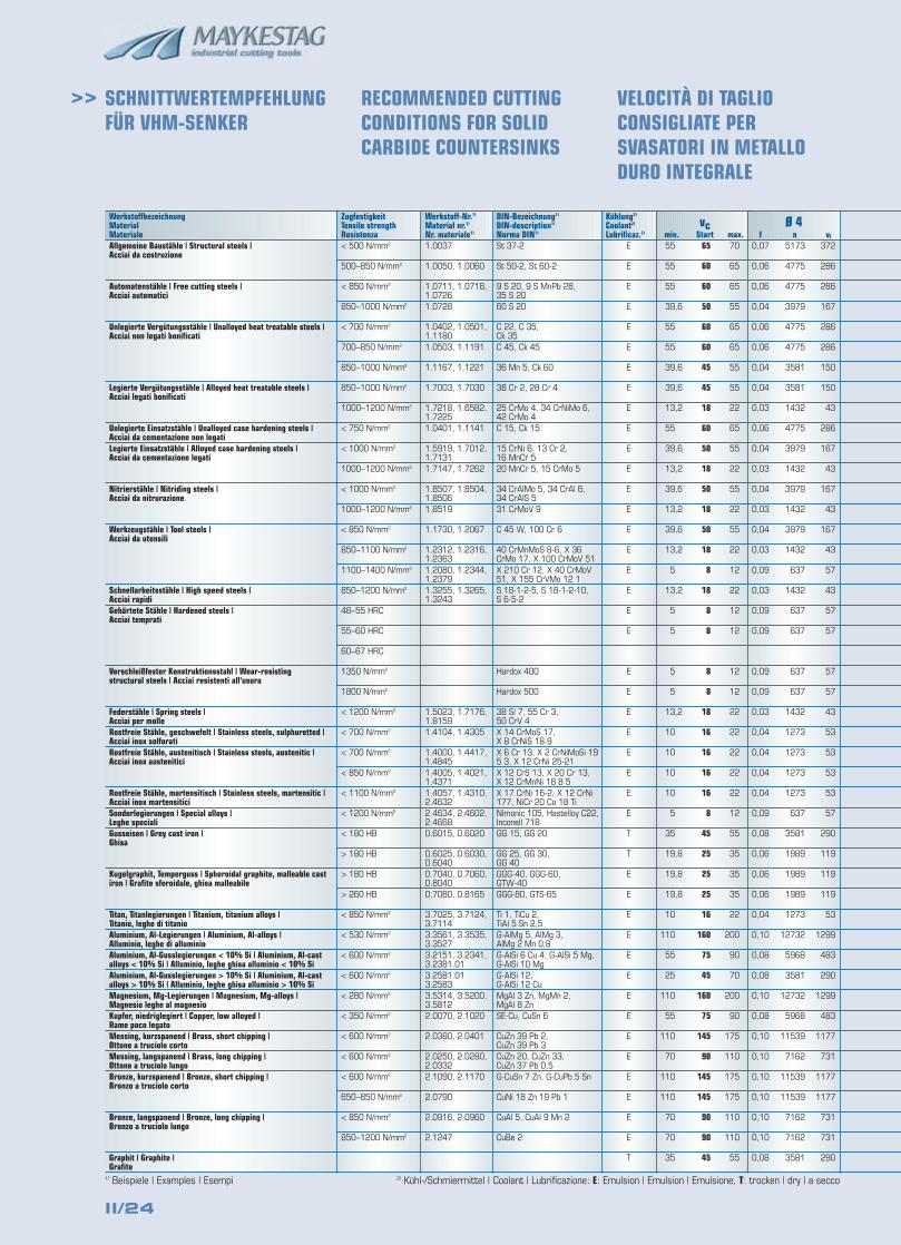
SCHNITTWERTEMPFEHLUNGFÜR VHM-SENKER
RECOMMENDED CUTTINGCONDITIONS FOR SOLIDCARBIDE COUNTERSINKS
VELOCITÀ DI TAGLIOCONSIGLIATE PERSVASATORI IN METALLODURO INTEGRALE
1) Beispiele | Examples | Esempi 2) Kühl-/Schmiermittel | Coolant | Lubrificazione: E: Emulsion | Emulsion | Emulsione, T: trocken | dry | a secco
55
55
55
39,6
55
55
39,6
39,6
13,2
55
39,6
13,2
39,6
13,2
39,6
13,2
5
13,2
5
5
5
5
13,2
10
10
10
10
5
35
19,8
19,8
19,8
10
110
55
25
110
55
110
70
110
110
70
70
35
65
60
60
50
60
60
45
45
18
60
50
18
50
18
50
18
8
18
8
8
8
8
18
16
16
16
16
8
45
25
25
25
16
160
75
45
160
75
145
90
145
145
90
90
45
70
65
65
55
65
65
55
55
22
65
55
22
55
22
55
22
12
22
12
12
12
12
22
22
22
22
22
12
55
35
35
35
22
200
90
70
200
90
175
110
175
175
110
110
55
II/25
Ø 63f n vf
0,35 328 115
0,30 303 91
0,30 303 91
0,25 253 64
0,30 303 91
0,30 303 91
0,25 227 57
0,25 227 57
0,16 91 15
0,30 303 91
0,25 253 64
0,16 91 15
0,25 253 64
0,16 91 15
0,25 253 64
0,16 91 15
0,14 40 6
0,16 91 15
0,14 40 6
0,14 40 6
0,14 40 6
0,14 40 6
0,16 91 15
0,14 81 11
0,14 81 11
0,14 81 11
0,14 81 11
0,14 40 6
0,32 227 73
0,28 126 36
0,28 126 36
0,28 126 36
0,14 81 11
0,40 808 325
0,30 379 114
0,30 227 68
0,40 808 325
0,30 379 114
0,40 733 295
0,40 455 183
0,40 733 295
0,40 733 295
0,40 455 183
0,40 455 183
0,32 227 73
Ø 40f n vf
0,25 517 130
0,22 477 106
0,22 477 106
0,18 398 72
0,22 477 106
0,22 477 106
0,18 358 64
0,18 358 64
0,12 143 17
0,22 477 106
0,18 398 72
0,12 143 17
0,18 398 72
0,12 143 17
0,18 398 72
0,12 143 17
0,12 64 8
0,12 143 17
0,12 64 8
0,12 64 8
0,12 64 8
0,12 64 8
0,12 143 17
0,12 127 15
0,12 127 15
0,12 127 15
0,12 127 15
0,12 64 8
0,30 358 107
0,25 199 50
0,25 199 50
0,25 199 50
0,12 127 15
0,30 1273 382
0,26 597 156
0,26 358 93
0,30 1273 382
0,26 597 156
0,30 1154 346
0,30 716 215
0,30 1154 346
0,30 1154 346
0,30 716 215
0,30 716 215
0,30 358 107
Ø 25f n vf
0,20 828 166
0,18 764 138
0,18 764 138
0,14 637 90
0,18 764 138
0,18 764 138
0,14 573 81
0,14 573 81
0,10 229 23
0,18 764 138
0,14 637 90
0,10 229 23
0,14 637 90
0,10 229 23
0,14 637 90
0,10 229 23
0,08 102 8
0,10 229 23
0,08 102 8
0,08 102 8
0,08 102 8
0,08 102 8
0,10 229 23
0,09 204 18
0,09 204 18
0,09 204 18
0,09 204 18
0,08 102 8
0,25 573 144
0,20 318 64
0,20 318 64
0,20 318 64
0,09 204 18
0,26 2037 532
0,22 955 212
0,22 573 127
0,26 2037 532
0,22 955 212
0,24 1846 443
0,24 1146 275
0,24 1846 443
0,24 1846 443
0,24 1146 275
0,24 1146 275
0,25 573 144
Ø 20f n vf
0,16 1035 168
0,14 955 135
0,14 955 135
0,12 796 95
0,14 955 135
0,14 955 135
0,12 716 86
0,12 716 86
0,08 286 23
0,14 955 135
0,12 796 95
0,08 286 23
0,12 796 95
0,08 286 23
0,12 796 95
0,08 286 23
0,06 127 8
0,08 286 23
0,06 127 8
0,06 127 8
0,06 127 8
0,06 127 8
0,08 286 23
0,08 255 21
0,08 255 21
0,08 255 21
0,08 255 21
0,06 127 8
0,20 716 144
0,16 398 64
0,16 398 64
0,16 398 64
0,08 255 21
0,22 2546 565
0,18 1194 215
0,18 716 129
0,22 2546 565
0,18 1194 215
0,20 2308 464
0,20 1432 288
0,20 2308 464
0,20 2308 464
0,20 1432 288
0,20 1432 288
0,20 716 144
Ø 16f n vf
0,14 1293 182
0,12 1194 143
0,12 1194 143
0,10 995 101
0,12 1194 143
0,12 1194 143
0,10 895 91
0,10 895 91
0,09 358 32
0,12 1194 143
0,10 995 101
0,09 358 32
0,10 995 101
0,09 358 32
0,10 995 101
0,09 358 32
0,05 159 8
0,09 358 32
0,05 159 8
0,05 159 8
0,05 159 8
0,05 159 8
0,09 358 32
0,07 318 23
0,07 318 23
0,07 318 23
0,07 318 23
0,05 159 8
0,16 895 145
0,12 497 60
0,12 497 60
0,12 497 60
0,07 318 23
0,18 3183 573
0,14 1492 210
0,14 895 126
0,18 3183 573
0,14 1492 210
0,18 2885 519
0,18 1790 322
0,18 2885 519
0,18 2885 519
0,18 1790 322
0,18 1790 322
0,16 895 145
Ø 10f n vf
0,12 2069 248
0,10 1910 195
0,10 1910 195
0,08 1592 129
0,10 1910 195
0,10 1910 195
0,08 1432 116
0,08 1432 116
0,05 573 29
0,10 1910 195
0,08 1592 129
0,05 573 29
0,08 1592 129
0,05 573 29
0,08 1592 129
0,05 573 29
0,04 255 11
0,05 573 29
0,04 255 11
0,04 255 11
0,04 255 11
0,04 255 11
0,05 573 29
0,06 509 31
0,06 509 31
0,06 509 31
0,06 509 31
0,04 255 11
0,12 1432 172
0,08 796 64
0,08 796 64
0,08 796 64
0,06 509 31
0,14 5093 718
0,12 2387 286
0,12 1432 172
0,14 5093 718
0,12 2387 286
0,14 4615 651
0,14 2865 404
0,14 4615 651
0,14 4615 651
0,14 2865 404
0,14 2865 404
0,12 1432 172
Ø 6f n vf
0,09 3448 310
0,08 3183 258
0,08 3183 258
0,06 2653 159
0,08 3183 258
0,08 3183 258
0,06 2387 143
0,06 2387 143
0,04 955 40
0,08 3183 258
0,06 2653 159
0,04 955 40
0,06 2653 159
0,04 955 40
0,06 2653 159
0,04 955 40
0,03 424 13
0,04 955 40
0,03 424 13
0,03 424 13
0,03 424 13
0,03 424 13
0,04 955 40
0,05 849 43
0,05 849 43
0,05 849 43
0,05 849 43
0,03 424 13
0,10 2387 244
0,07 1326 95
0,07 1326 95
0,07 1326 95
0,05 849 43
0,12 8488 1019
0,10 3979 406
0,10 2387 244
0,12 8488 1019
0,10 3979 406
0,12 7692 923
0,12 4775 573
0,12 7692 923
0,12 7692 923
0,12 4775 573
0,12 4775 573
0,10 2387 244
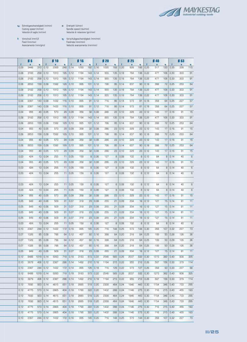
vc: Schnittgeschwindigkeit [m/min]Cutting speed [m/min]Velocità di taglio [m/min]
f: Vorschub [mm/U]Feed [mm/rev]Avanzamento [mm/giro]
n: Drehzahl [U/min]Spindle speed [rev/min]Velocità di rotazione [giri/min]
vf: Vorschubgeschwindigkeit [mm/min]Feedrate [mm/min]Velocità avanzamento [mm/min]
II/26
>>
Werkstoffbezeichnung MaterialMateriale
Ø 5f n vf
0,15 828 124
0,15 637 95
0,15 637 95
0,15 509 76
0,15 828 124
0,15 637 95
0,15 509 76
0,15 637 95
0,12 509 61
0,15 828 124
0,15 637 95
0,12 509 61
0,15 637 95
0,12 509 61
0,15 637 95
0,12 509 61
0,12 382 46
0,12 382 46
0,12 509 61
0,12 509 61
0,15 828 124
0,15 828 124
0,15 637 95
0,12 509 61
0,12 509 61
0,15 637 95
0,12 509 61
0,15 637 95
0,15 637 95
0,15 637 95
0,20 1592 318
0,20 1273 255
0,20 1273 255
0,20 1592 318
0,30 1592 477
0,20 1273 255
0,20 1273 255
0,20 1273 255
0,20 828 166
0,20 828 166
0,20 637 127
0,15 637 95
vcmin. Start max.
O/E
O/E
O/E
O/E
O/E
O/E
O/E
O/E
O/E
O/E
O/E
O/E
O/E
O/E
O/E
O/E
O/E
O/E
E
E
E
E
E
E
E
T/O
T/O
T/E
T/E
E
E
E
E
E
E
T/E
T/E
T/E
T/E
T/E
T/E
T
Kühlung2)
Coolant2)
Lubrificaz.2)
St 37-2
St 50-2, St 60-2
9 S 20, 9 S MnPb 28,35 S 2060 S 20
C 22, C 35,Ck 35C 45, Ck 45
36 Mn 5, Ck 60
38 Cr 2, 28 Cr 4
25 CrMo 4, 34 CrNiMo 6,42 CrMo 4C 15, Ck 15
15 CrNi 6, 13 Cr 2,16 MnCr 520 MnCr 5, 15 CrMo 5
34 CrAlMo 5, 34 CrAl 6,34 CrAlS 531 CrMoV 9
C 45 W, 100 Cr 6
40 CrMnMoS 8-6, X 36CrMo 17, X 100 CrMoV 51X 210 Cr 12, X 40 CrMoV51, X 155 CrVMo 12 1S 18-1-2-5, S 18-1-2-10, S 6-5-2
Hardox 400
Hardox 500
38 Si 7, 55 Cr 3, 50 CrV 4X 14 CrMoS 17,X 8 CrNiS 18-9X 6 Cr 13, X 2 CrNiMoSi 195 3, X 12 CrNi 25-21X 12 CrS 13, X 20 Cr 13,X 12 CrMnNi 18 8 5X 17 CrNi 16-2, X 12 CrNi177, NiCr 20 Co 18 TiNimonic 105, Hastelloy C22,Inconell 718GG 15, GG 20
GG 25, GG 30, GG 40GGG-40, GGG-60,GTW-40GGG-80, GTS-65
Ti 1, TiCu 2, TiAl 5 Sn 2,5G-AlMg 5, AlMg 3,AlMg 2 Mn 0,8G-AlSi 6 Cu 4, G-AlSi 5 Mg,G-AlSi 10 MgG-AlSi 12,G-AlSi 12 CuMgAl 3 Zn, MgMn 2,MgAl 8 ZnSE-Cu, CuSn 6
CuZn 39 Pb 2,CuZn 39 Pb 3CuZn 20, CuZn 33,CuZn 37 Pb 0,5G-CuSn 7 Zn, G-CuPb 5 Sn
CuNi 18 Zn 19 Pb 1
CuAl 5, CuAl 9 Mn 2
CuBe 2
DIN-Bezeichnung1)
DIN-description1)
Norma DIN1)
Werkstoff-Nr.1)
Material nr.1)
Nr. materiale1)
1.0037
1.0050, 1.0060
1.0711, 1.0718,1.07261.0728
1.0402, 1.0501,1.11801.0503, 1.1191
1.1167, 1.1221
1.7003, 1.7030
1.7218, 1.6582,1.72251.0401, 1.1141
1.5919, 1.7012,1.71311.7147, 1.7262
1.8507, 1.8504,1.85061.8519
1.1730, 1.2067
1.2312, 1.2316,1.23631.2080, 1.2344,1.23791.3255, 1.3265,1.3243
1.5023, 1.7176,1.81591.4104, 1.4305
1.4000, 1.4417,1.48451.4005, 1.4021,1.43711.4057, 1.4310,2.46322.4634, 2.4602,2.46680.6015, 0.6020
0.6025, 0.6030,0.60400.7040, 0.7060,0.80400.7080, 0.8165
3.7025, 3.7124,3.71143.3561, 3.3535,3.35273.2151, 3.2341,3.2381.013.2581.013.25833.5314, 3.5200,3.58122.0070, 2.1020
2.0380, 2.0401
2.0250, 2.0280,2.03322.1090, 2.1170
2.0790
2.0916, 2.0960
2.1247
ZugfestigkeitTensile strengthResistenza< 500 N/mm2
500–850 N/mm2
< 850 N/mm2
850–1000 N/mm2
< 700 N/mm2
700–850 N/mm2
850–1000 N/mm2
850–1000 N/mm2
1000–1200 N/mm2
< 750 N/mm2
< 1000 N/mm2
1000–1200 N/mm2
< 1000 N/mm2
1000–1200 N/mm2
< 850 N/mm2
850–1100 N/mm2
1100–1400 N/mm2
850–1200 N/mm2
48–55 HRC
55–60 HRC
60–67 HRC
1350 N/mm2
1800 N/mm2
< 1200 N/mm2
< 700 N/mm2
< 700 N/mm2
< 850 N/mm2
< 1100 N/mm2
< 1200 N/mm2
< 180 HB
> 180 HB
> 180 HB
> 260 HB
< 850 N/mm2
< 530 N/mm2
< 600 N/mm2
< 600 N/mm2
< 280 N/mm2
< 350 N/mm2
< 600 N/mm2
< 600 N/mm2
< 600 N/mm2
650–850 N/mm2
< 850 N/mm2
850–1200 N/mm2
Allgemeine Baustähle | Structural steels | Acciai da costruzione
Automatenstähle | Free cutting steels | Acciai automatici
Unlegierte Vergütungsstähle | Unalloyed heat treatable steels | Acciai non legati bonificati
Legierte Vergütungsstähle | Alloyed heat treatable steels | Acciai legati bonificati
Unlegierte Einsatzstähle | Unalloyed case hardening steels | Acciai da cementazione non legatiLegierte Einsatzstähle | Alloyed case hardening steels | Acciai da cementazione legati
Nitrierstähle | Nitriding steels | Acciai da nitrurazione
Werkzeugstähle | Tool steels | Acciai da utensili
Schnellarbeitsstähle | High speed steels | Acciai rapidiGehärtete Stähle | Hardened steels | Acciai temprati
Verschleißfester Konstruktionsstahl | Wear-resisting structural steels | Acciai resistenti all'usura
Federstähle | Spring steels | Acciai per molleRostfreie Stähle, geschwefelt | Stainless steels, sulphuretted | Acciai inox solforatiRostfreie Stähle, austenitisch | Stainless steels, austenitic | Acciai inox austenitici
Rostfreie Stähle, martensitisch | Stainless steels, martensitic | Acciai inox martensiticiSonderlegierungen | Special alloys | Leghe specialiGusseisen | Grey cast iron | Ghisa
Kugelgraphit, Temperguss | Spheroidal graphite, malleable cast iron | Grafite sferoidale, ghisa malleabile
Titan, Titanlegierungen | Titanium, titanium alloys | Titanio, leghe di titanioAluminium, Al-Legierungen | Aluminium, Al-alloys | Alluminio, leghe di alluminioAluminium, Al-Gusslegierungen < 10% Si | Aluminium, Al-cast alloys < 10% Si | Alluminio, leghe ghisa alluminio < 10% SiAluminium, Al-Gusslegierungen > 10% Si | Aluminium, Al-cast alloys > 10% Si | Alluminio, leghe ghisa alluminio > 10% SiMagnesium, Mg-Legierungen | Magnesium, Mg-alloys | Magnesio leghe al magnesioKupfer, niedriglegiert | Copper, low alloyed | Rame poco legatoMessing, kurzspanend | Brass, short chipping | Ottone a truciolo cortoMessing, langspanend | Brass, long chipping | Ottone a truciolo lungoBronze, kurzspanend | Bronze, short chipping | Bronzo a truciolo corto
Bronze, langspanend | Bronze, long chipping | Bronzo a truciolo lungo
Graphit | Graphite | Grafite
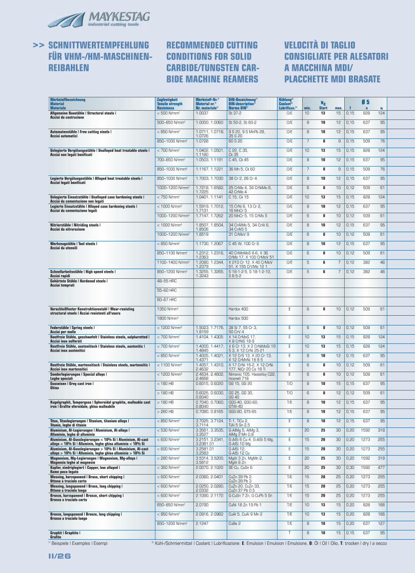
SCHNITTWERTEMPFEHLUNGFÜR VHM-/HM-MASCHINEN-REIBAHLEN
RECOMMENDED CUTTINGCONDITIONS FOR SOLIDCARBIDE/TUNGSTEN CAR-BIDE MACHINE REAMERS
VELOCITÀ DI TAGLIOCONSIGLIATE PER ALESATORI A MACCHINA MDI/PLACCHETTE MDI BRASATE
1) Beispiele | Examples | Esempi 2) Kühl-/Schmiermittel | Coolant | Lubrificazione: E: Emulsion | Emulsion | Emulsione, O: Öl | Oil | Olio, T: trocken | dry | a secco
10
8
8
7
10
8
7
8
6
10
8
6
8
6
8
6
5
5
6
6
10
10
8
6
6
8
6
8
8
8
20
15
15
20
20
15
15
15
10
10
8
8
13
10
10
8
13
10
8
10
8
13
10
8
10
8
10
8
6
6
8
8
13
13
10
8
8
10
8
10
10
10
25
20
20
25
25
20
20
20
13
13
10
10
15
12
12
9
15
12
9
12
10
15
12
10
12
10
12
10
7
7
10
10
15
15
12
10
10
15
12
12
12
12
30
30
30
30
30
25
25
25
15
15
15
15
II/27
Ø 50f n vf
0,50 83 41
0,50 64 32
0,50 64 32
0,50 51 25
0,50 83 41
0,50 64 32
0,50 51 25
0,50 64 32
0,40 51 20
0,50 83 41
0,50 64 32
0,40 51 20
0,50 64 32
0,40 51 20
0,50 64 32
0,40 51 20
0,40 38 15
0,40 38 15
0,40 51 20
0,40 51 20
0,50 83 41
0,50 83 41
0,50 64 32
0,40 51 20
0,40 51 20
0,60 64 38
0,50 51 25
0,50 64 32
0,50 64 32
0,50 64 32
0,40 51 20
0,60 127 76
0,60 127 76
0,60 159 95
0,70 159 111
0,60 127 76
0,60 127 76
0,60 127 76
0,60 83 50
0,60 83 50
0,60 64 38
0,60 64 38
Ø 40f n vf
0,40 103 41
0,40 80 32
0,40 80 32
0,40 64 25
0,40 103 41
0,40 80 32
0,40 64 25
0,40 80 32
0,30 64 19
0,40 103 41
0,40 80 32
0,30 64 19
0,40 80 32
0,30 64 19
0,40 80 32
0,30 64 19
0,30 48 14
0,30 48 14
0,30 64 19
0,30 64 19
0,40 103 41
0,40 103 41
0,40 80 32
0,30 64 19
0,30 64 19
0,50 80 40
0,40 64 25
0,40 80 32
0,40 80 32
0,40 80 32
0,30 64 19
0,50 159 80
0,50 159 80
0,50 199 99
0,60 199 119
0,50 159 80
0,50 159 80
0,50 159 80
0,50 103 52
0,50 103 52
0,50 80 40
0,50 80 40
Ø 30f n vf
0,35 138 48
0,35 106 37
0,35 106 37
0,35 85 30
0,35 138 48
0,35 106 37
0,35 85 30
0,35 106 37
0,25 85 21
0,35 138 48
0,35 106 37
0,25 85 21
0,35 106 37
0,25 85 21
0,35 106 37
0,25 85 21
0,25 64 16
0,25 64 16
0,25 85 21
0,25 85 21
0,35 138 48
0,35 138 48
0,35 106 37
0,25 85 21
0,25 85 21
0,45 106 48
0,35 85 30
0,35 106 37
0,35 106 37
0,35 106 37
0,25 85 21
0,45 212 95
0,45 212 95
0,45 265 119
0,55 265 146
0,45 212 95
0,45 212 95
0,45 212 95
0,45 138 62
0,45 138 62
0,45 106 48
0,45 106 48
Ø 25f n vf
0,30 166 50
0,30 127 38
0,30 127 38
0,30 102 31
0,30 166 50
0,30 127 38
0,30 102 31
0,30 127 38
0,20 102 20
0,30 166 50
0,30 127 38
0,20 102 20
0,30 127 38
0,20 102 20
0,30 127 38
0,20 102 20
0,20 76 15
0,20 76 15
0,20 102 20
0,20 102 20
0,30 166 50
0,30 166 50
0,30 127 38
0,20 102 20
0,20 102 20
0,30 127 38
0,30 102 31
0,30 127 38
0,30 127 38
0,30 127 38
0,20 102 20
0,40 255 102
0,40 255 102
0,40 318 127
0,50 318 159
0,40 255 102
0,40 255 102
0,40 255 102
0,40 166 66
0,40 166 66
0,40 127 51
0,30 127 38
Ø 20f n vf
0,30 207 62
0,30 159 48
0,30 159 48
0,30 127 38
0,30 207 62
0,30 159 48
0,30 127 38
0,30 159 48
0,20 127 25
0,30 207 62
0,30 159 48
0,20 127 25
0,30 159 48
0,20 127 25
0,30 159 48
0,20 127 25
0,20 95 19
0,20 95 19
0,20 127 25
0,20 127 25
0,30 207 62
0,30 207 62
0,30 159 48
0,20 127 25
0,20 127 25
0,30 159 48
0,30 127 38
0,30 159 48
0,30 159 48
0,30 159 48
0,20 127 25
0,40 318 127
0,40 318 127
0,40 398 159
0,50 398 199
0,40 318 127
0,40 318 127
0,40 318 127
0,40 207 83
0,40 207 83
0,40 159 64
0,30 159 48
Ø 15f n vf
0,25 276 69
0,25 212 53
0,25 212 53
0,25 170 42
0,25 276 69
0,25 212 53
0,25 170 42
0,25 212 53
0,18 170 31
0,25 276 69
0,25 212 53
0,18 170 31
0,25 212 53
0,18 170 31
0,25 212 53
0,18 170 31
0,18 127 23
0,18 127 23
0,18 170 31
0,18 170 31
0,25 276 69
0,25 276 69
0,25 212 53
0,18 170 31
0,18 170 31
0,25 212 53
0,25 170 42
0,25 212 53
0,25 212 53
0,25 212 53
0,18 170 31
0,35 424 149
0,35 424 149
0,35 531 186
0,45 531 239
0,35 424 149
0,35 424 149
0,35 424 149
0,35 276 97
0,35 276 97
0,35 212 79
0,25 212 53
Ø 10f n vf
0,20 414 83
0,20 318 64
0,20 318 64
0,20 255 51
0,20 414 83
0,20 318 64
0,20 255 51
0,20 318 64
0,15 255 38
0,20 414 83
0,20 318 64
0,15 255 38
0,20 318 64
0,15 255 38
0,20 318 64
0,15 255 38
0,15 191 29
0,15 191 29
0,15 255 38
0,15 255 38
0,20 414 83
0,20 414 83
0,20 318 64
0,15 255 38
0,15 255 38
0,20 318 64
0,20 255 51
0,20 318 64
0,20 318 64
0,20 318 64
0,30 796 239
0,30 637 191
0,30 637 191
0,30 796 239
0,40 796 318
0,30 637 191
0,30 637 191
0,30 637 191
0,30 414 124
0,30 414 124
0,30 318 95
0,20 318 64
Ø 8f n vf
0,18 517 93
0,18 398 72
0,18 398 72
0,18 318 57
0,18 517 93
0,18 398 72
0,18 318 57
0,18 398 72
0,15 318 48
0,18 517 93
0,18 398 72
0,15 318 48
0,18 398 72
0,15 318 48
0,18 398 72
0,15 318 48
0,15 239 36
0,15 239 36
0,15 318 48
0,15 318 48
0,18 517 93
0,18 517 93
0,18 398 72
0,15 318 48
0,15 318 48
0,18 398 72
0,15 318 48
0,18 398 72
0,18 398 72
0,18 398 72
0,26 995 259
0,26 796 207
0,26 796 207
0,26 995 259
0,36 995 358
0,26 796 207
0,26 796 207
0,26 796 207
0,26 517 134
0,26 517 134
0,26 398 103
0,18 398 72
vc: Schnittgeschwindigkeit [m/min]Cutting speed [m/min]Velocità di taglio [m/min]
f: Vorschub [mm/U]Feed [mm/rev]Avanzamento [mm/giro]
n: Drehzahl [U/min]Spindle speed [rev/min]Velocità di rotazione [giri/min]
vf: Vorschubgeschwindigkeit [mm/min]Feedrate [mm/min]Velocità avanzamento [mm/min]
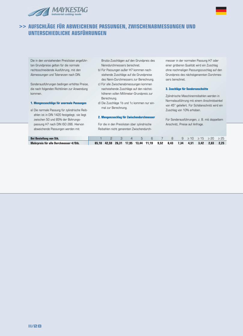
II/28
>> AUFSCHLÄGE FÜR ABWEICHENDE PASSUNGEN, ZWISCHENABMESSUNGEN UND UNTERSCHIEDLICHE AUSFÜHRUNGEN
Die in den vorstehenden Preislisten angeführ-
ten Grundpreise gelten für die normale
rechtsschneidende Ausführung, mit den
Abmessungen und Toleranzen nach DIN.
Sonderausführungen bedingen erhöhte Preise,
die nach folgenden Richtlinien zur Anwendung
kommen.
1. Mengenzuschläge für anormale Passungen
a) Die normale Passung für zylindrische Reib-
ahlen ist in DIN 1420 festgelegt; sie liegt
zwischen 50 und 85% der Bohrungs-
passung H7 nach DIN ISO 286. Hiervon
abweichende Passungen werden mit
Brutto-Zuschlägen auf den Grundpreis des
Nenndurchmessers berechnet.
b) Für Passungen außer H7 kommen nach-
stehende Zuschläge auf die Grundpreise
des Nenn-Durchmessers zur Berechnung.
c) Für alle Zwischenabmessungen kommen
nachstehende Zuschläge auf den nächst-
höheren vollen Millimeter-Grundpreis zur
Berechnung.
d) Die Zuschläge 1b und 1c kommen nur ein-
mal zur Berechnung.
2. Mengenzuschlag für Zwischendurchmesser
Für die in den Preislisten über zylindrische
Reibahlen nicht genannten Zwischendurch-
messer in der normalen Passung H7 oder
einer gröberen Qualität wird ein Zuschlag
ohne nochmaligen Passungszuschlag auf den
Grundpreis des nächstgenannten Durchmes-
sers berechnet.
3. Zuschläge für Sonderanschnitte
Zylindrische Maschinenreibahlen werden in
Normalausführung mit einem Anschnittwinkel
von 45° geliefert. Für Schälanschnitt wird ein
Zuschlag von 10% erhoben.
Für Sonderausführungen, z. B. mit doppeltem
Anschnitt, Preise auf Anfrage.
Bei Bestellung von Stk. 1 2 3 4 5 6 7 8 9 ≥ 10 ≥ 15 ≥ 20 ≥ 25
Mehrpreis für alle Durchmesser €/Stk. 85,10 42,59 26,31 17,95 13,44 11,19 9,52 8,43 7,34 4,51 3,42 2,83 2,25
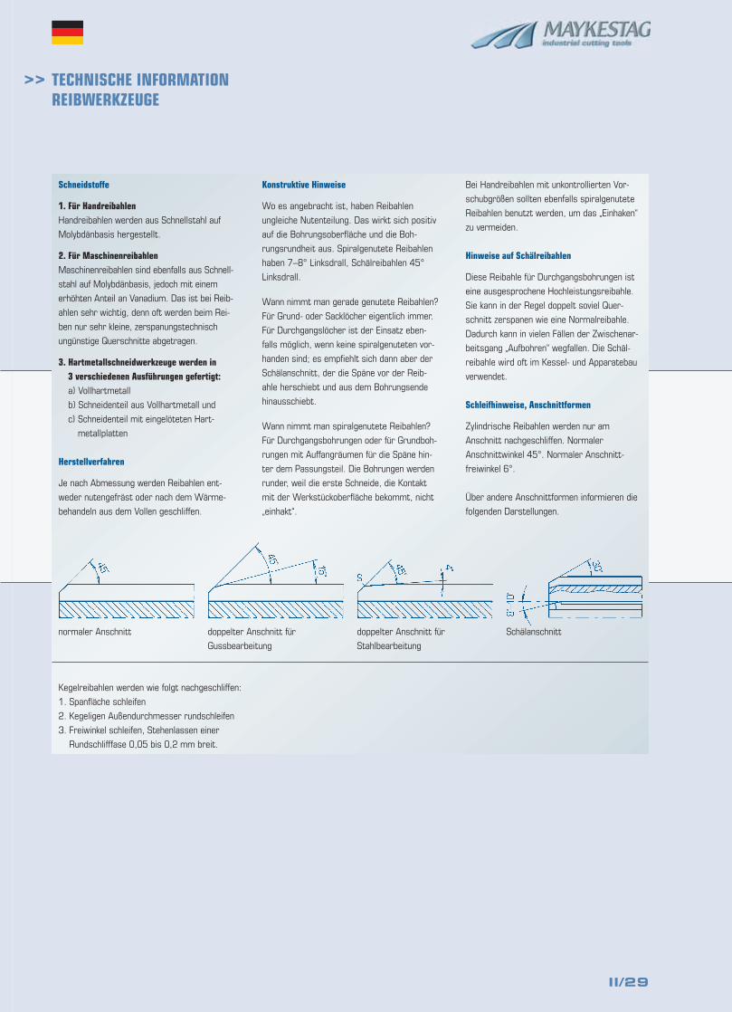
II/29
>> TECHNISCHE INFORMATIONREIBWERKZEUGE
Schneidstoffe
1. Für HandreibahlenHandreibahlen werden aus Schnellstahl auf
Molybdänbasis hergestellt.
2. Für MaschinenreibahlenMaschinenreibahlen sind ebenfalls aus Schnell-
stahl auf Molybdänbasis, jedoch mit einem
erhöhten Anteil an Vanadium. Das ist bei Reib-
ahlen sehr wichtig, denn oft werden beim Rei-
ben nur sehr kleine, zerspanungstechnisch
ungünstige Querschnitte abgetragen.
3. Hartmetallschneidwerkzeuge werden in 3 verschiedenen Ausführungen gefertigt:a) Vollhartmetall
b) Schneidenteil aus Vollhartmetall und
c) Schneidenteil mit eingelöteten Hart-
metallplatten
Herstellverfahren
Je nach Abmessung werden Reibahlen ent-
weder nutengefräst oder nach dem Wärme-
behandeln aus dem Vollen geschliffen.
Konstruktive Hinweise
Wo es angebracht ist, haben Reibahlen
ungleiche Nutenteilung. Das wirkt sich positiv
auf die Bohrungsoberfläche und die Boh-
rungsrundheit aus. Spiralgenutete Reibahlen
haben 7–8° Linksdrall, Schälreibahlen 45°
Linksdrall.
Wann nimmt man gerade genutete Reibahlen?
Für Grund- oder Sacklöcher eigentlich immer.
Für Durchgangslöcher ist der Einsatz eben-
falls möglich, wenn keine spiralgenuteten vor-
handen sind; es empfiehlt sich dann aber der
Schälanschnitt, der die Späne vor der Reib-
ahle herschiebt und aus dem Bohrungsende
hinausschiebt.
Wann nimmt man spiralgenutete Reibahlen?
Für Durchgangsbohrungen oder für Grundboh-
rungen mit Auffangräumen für die Späne hin-
ter dem Passungsteil. Die Bohrungen werden
runder, weil die erste Schneide, die Kontakt
mit der Werkstückoberfläche bekommt, nicht
„einhakt“.
Bei Handreibahlen mit unkontrollierten Vor-
schubgrößen sollten ebenfalls spiralgenutete
Reibahlen benutzt werden, um das „Einhaken“
zu vermeiden.
Hinweise auf Schälreibahlen
Diese Reibahle für Durchgangsbohrungen ist
eine ausgesprochene Hochleistungsreibahle.
Sie kann in der Regel doppelt soviel Quer-
schnitt zerspanen wie eine Normalreibahle.
Dadurch kann in vielen Fällen der Zwischenar-
beitsgang „Aufbohren“ wegfallen. Die Schäl-
reibahle wird oft im Kessel- und Apparatebau
verwendet.
Schleifhinweise, Anschnittformen
Zylindrische Reibahlen werden nur am
Anschnitt nachgeschliffen. Normaler
Anschnittwinkel 45°. Normaler Anschnitt-
freiwinkel 6°.
Über andere Anschnittformen informieren die
folgenden Darstellungen.
Kegelreibahlen werden wie folgt nachgeschliffen:
1. Spanfläche schleifen
2. Kegeligen Außendurchmesser rundschleifen
3. Freiwinkel schleifen, Stehenlassen einer
Rundschlifffase 0,05 bis 0,2 mm breit.
normaler Anschnitt doppelter Anschnitt für
Gussbearbeitung
doppelter Anschnitt für
Stahlbearbeitung
Schälanschnitt
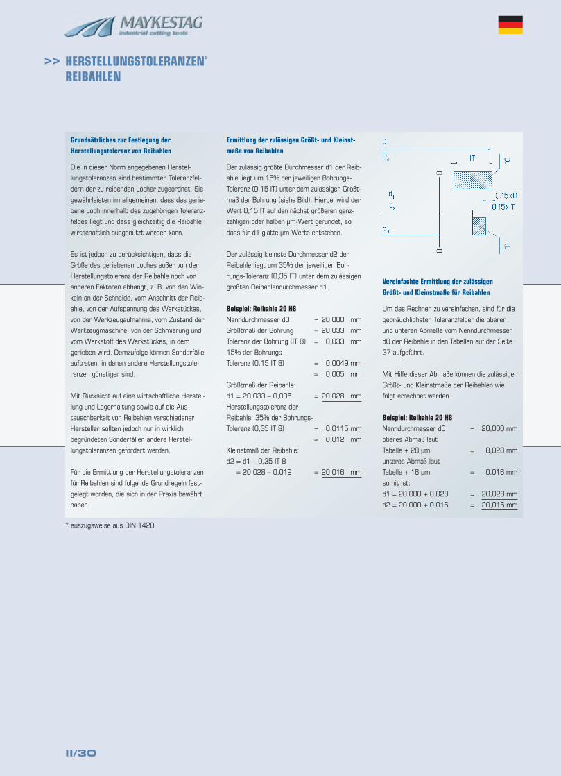
II/30
>> HERSTELLUNGSTOLERANZEN*
REIBAHLEN
Grundsätzliches zur Festlegung derHerstellungstoleranz von Reibahlen
Die in dieser Norm angegebenen Herstel-
lungstoleranzen sind bestimmten Toleranzfel-
dern der zu reibenden Löcher zugeordnet. Sie
gewährleisten im allgemeinen, dass das gerie-
bene Loch innerhalb des zugehörigen Toleranz-
feldes liegt und dass gleichzeitig die Reibahle
wirtschaftlich ausgenutzt werden kann.
Es ist jedoch zu berücksichtigen, dass die
Größe des geriebenen Loches außer von der
Herstellungstoleranz der Reibahle noch von
anderen Faktoren abhängt, z. B. von den Win-
keln an der Schneide, vom Anschnitt der Reib-
ahle, von der Aufspannung des Werkstückes,
von der Werkzeugaufnahme, vom Zustand der
Werkzeugmaschine, von der Schmierung und
vom Werkstoff des Werkstückes, in dem
gerieben wird. Demzufolge können Sonderfälle
auftreten, in denen andere Herstellungstole-
ranzen günstiger sind.
Mit Rücksicht auf eine wirtschaftliche Herstel-
lung und Lagerhaltung sowie auf die Aus-
tauschbarkeit von Reibahlen verschiedener
Hersteller sollten jedoch nur in wirklich
begründeten Sonderfällen andere Herstel-
lungstoleranzen gefordert werden.
Für die Ermittlung der Herstellungstoleranzen
für Reibahlen sind folgende Grundregeln fest-
gelegt worden, die sich in der Praxis bewährt
haben.
Ermittlung der zulässigen Größt- und Kleinst-maße von Reibahlen
Der zulässig größte Durchmesser d1 der Reib-
ahle liegt um 15% der jeweiligen Bohrungs-
Toleranz (0,15 IT) unter dem zulässigen Größt-
maß der Bohrung (siehe Bild). Hierbei wird der
Wert 0,15 IT auf den nächst größeren ganz-
zahligen oder halben µm-Wert gerundet, so
dass für d1 glatte µm-Werte entstehen.
Der zulässig kleinste Durchmesser d2 der
Reibahle liegt um 35% der jeweiligen Boh-
rungs-Toleranz (0,35 IT) unter dem zulässigen
größten Reibahlendurchmesser d1.
Beispiel: Reibahle 20 H8Nenndurchmesser d0 = 20,000 mm
Größtmaß der Bohrung = 20,033 mm
Toleranz der Bohrung (IT 8) = 0,033 mm
15% der Bohrungs-
Toleranz (0,15 IT 8) = 0,0049 mm
≈ 0,005 mm
Größtmaß der Reibahle:
d1 = 20,033 – 0,005 = 20,028 mm
Herstellungstoleranz der
Reibahle: 35% der Bohrungs-
Toleranz (0,35 IT 8) = 0,0115 mm
≈ 0,012 mm
Kleinstmaß der Reibahle:
d2 = d1 – 0,35 IT 8
= 20,028 – 0,012 = 20,016 mm
Vereinfachte Ermittlung der zulässigen Größt- und Kleinstmaße für Reibahlen
Um das Rechnen zu vereinfachen, sind für die
gebräuchlichsten Toleranzfelder die oberen
und unteren Abmaße vom Nenndurchmesser
d0 der Reibahle in den Tabellen auf der Seite
37 aufgeführt.
Mit Hilfe dieser Abmaße können die zulässigen
Größt- und Kleinstmaße der Reibahlen wie
folgt errechnet werden.
Beispiel: Reibahle 20 H8Nenndurchmesser d0 = 20,000 mm
oberes Abmaß laut
Tabelle + 28 µm = 0,028 mm
unteres Abmaß laut
Tabelle + 16 µm = 0,016 mm
somit ist:
d1 = 20,000 + 0,028 = 20,028 mm
d2 = 20,000 + 0,016 = 20,016 mm
* auszugsweise aus DIN 1420
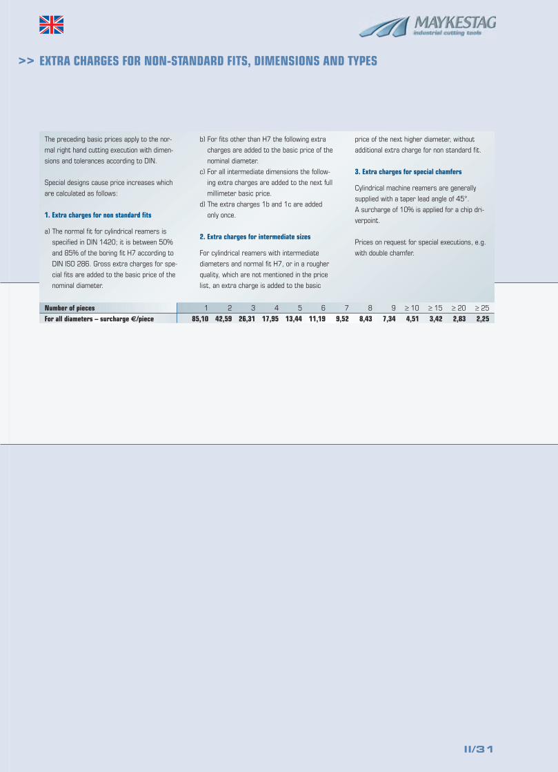
II/31
>> EXTRA CHARGES FOR NON-STANDARD FITS, DIMENSIONS AND TYPES
The preceding basic prices apply to the nor-
mal right hand cutting execution with dimen-
sions and tolerances according to DIN.
Special designs cause price increases which
are calculated as follows:
1. Extra charges for non standard fits
a) The normal fit for cylindrical reamers is
specified in DIN 1420; it is between 50%
and 85% of the boring fit H7 according to
DIN ISO 286. Gross extra charges for spe-
cial fits are added to the basic price of the
nominal diameter.
b) For fits other than H7 the following extra
charges are added to the basic price of the
nominal diameter.
c) For all intermediate dimensions the follow-
ing extra charges are added to the next full
millimeter basic price.
d) The extra charges 1b and 1c are added
only once.
2. Extra charges for intermediate sizes
For cylindrical reamers with intermediate
diameters and normal fit H7, or in a rougher
quality, which are not mentioned in the price
list, an extra charge is added to the basic
price of the next higher diameter, without
additional extra charge for non standard fit.
3. Extra charges for special chamfers
Cylindrical machine reamers are generally
supplied with a taper lead angle of 45°.
A surcharge of 10% is applied for a chip dri-
verpoint.
Prices on request for special executions, e.g.
with double chamfer.
Number of pieces 1 2 3 4 5 6 7 8 9 ≥ 10 ≥ 15 ≥ 20 ≥ 25
For all diameters – surcharge €/piece 85,10 42,59 26,31 17,95 13,44 11,19 9,52 8,43 7,34 4,51 3,42 2,83 2,25
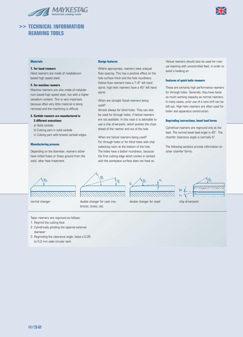
II/32
>> TECHNICAL INFORMATIONREAMING TOOLS
Materials
1. For hand reamersHand reamers are made of molybdenum
based high speed steel.
2. For machine reamersMachine reamers are also made of molybde-
num based high speed steel, but with a higher
vanadium content. This is very important,
because often very little material is being
removed and the machining is difficult.
3. Carbide reamers are manufactured in 3 different executions:a) Solid carbide
b) Cutting part in solid carbide
c) Cutting part with brazed carbide edges
Manufacturing process
Depending on the diameter, reamers either
have milled flutes or flutes ground from the
solid, after heat treatment.
Design features
Where appropriate, reamers have unequal
flute spacing. This has a positive effect on the
hole surface finish and the hole roundness.
Helical flute reamers have a 7–8° left hand
spiral, high helix reamers have a 45° left hand
spiral.
When are straight fluted reamers being
used?
Almost always for blind holes. They can also
be used for through holes, if helical reamers
are not available. In this case it is advisable to
use a chip driverpoint, which pushes the chips
ahead of the reamer and out of the hole.
When are helical reamers being used?
For through holes or for blind holes with chip
collecting room at the bottom of the hole.
The holes have a better roundness, because
the first cutting edge which comes in contact
with the workpiece surface does not hook on.
Helical reamers should also be used for man-
ual reaming with uncontrolled feed, in order to
avoid a hooking on.
Features of quick helix reamers
These are certainly high performance reamers
for through holes. Generally, they have twice
as much working capacity as normal reamers.
In many cases, prior use of a core drill can be
left out. High helix reamers are often used for
boiler and apparatus construction.
Regrinding instructions, bevel lead forms
Cylindrical reamers are reground only at the
lead. The normal bevel lead angle is 45°. The
chamfer clearance angle is normally 6°.
The following sections provide information on
other chamfer forms.
Taper reamers are reground as follows:
1. Regrind the cutting face
2. Cylindrically grinding the tapered external
diameter
3. Regrinding the clearance angle; leave a 0,05
to 0,2 mm wide circular land.
normal changer double changer for cast iron,
bronze, brass, etc.
double changer for steel chip driverpoint
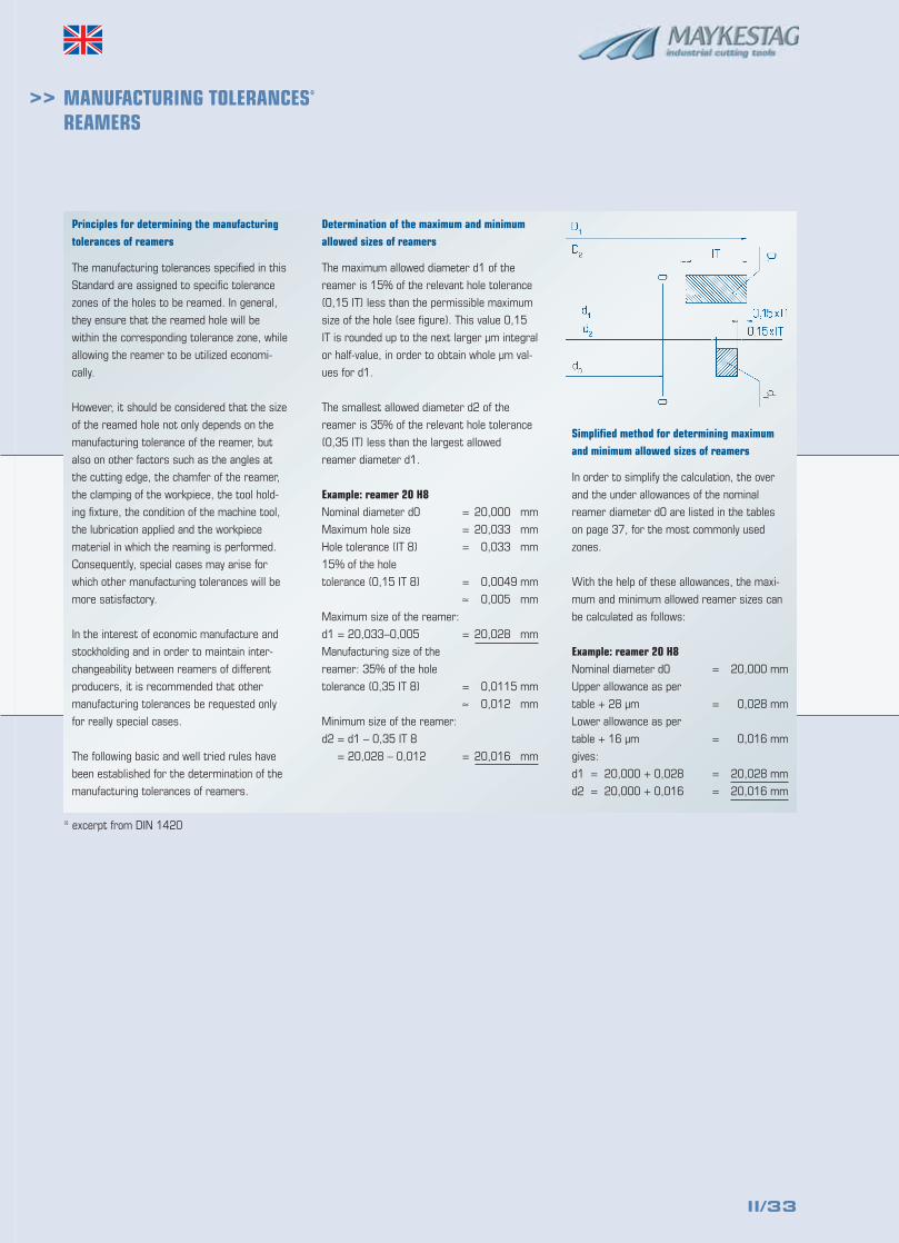
II/33
>> MANUFACTURING TOLERANCES*
REAMERS
Principles for determining the manufacturingtolerances of reamers
The manufacturing tolerances specified in this
Standard are assigned to specific tolerance
zones of the holes to be reamed. In general,
they ensure that the reamed hole will be
within the corresponding tolerance zone, while
allowing the reamer to be utilized economi-
cally.
However, it should be considered that the size
of the reamed hole not only depends on the
manufacturing tolerance of the reamer, but
also on other factors such as the angles at
the cutting edge, the chamfer of the reamer,
the clamping of the workpiece, the tool hold-
ing fixture, the condition of the machine tool,
the lubrication applied and the workpiece
material in which the reaming is performed.
Consequently, special cases may arise for
which other manufacturing tolerances will be
more satisfactory.
In the interest of economic manufacture and
stockholding and in order to maintain inter-
changeability between reamers of different
producers, it is recommended that other
manufacturing tolerances be requested only
for really special cases.
The following basic and well tried rules have
been established for the determination of the
manufacturing tolerances of reamers.
Determination of the maximum and minimumallowed sizes of reamers
The maximum allowed diameter d1 of the
reamer is 15% of the relevant hole tolerance
(0,15 IT) less than the permissible maximum
size of the hole (see figure). This value 0,15
IT is rounded up to the next larger µm integral
or half-value, in order to obtain whole µm val-
ues for d1.
The smallest allowed diameter d2 of the
reamer is 35% of the relevant hole tolerance
(0,35 IT) less than the largest allowed
reamer diameter d1.
Example: reamer 20 H8Nominal diameter d0 = 20,000 mm
Maximum hole size = 20,033 mm
Hole tolerance (IT 8) = 0,033 mm
15% of the hole
tolerance (0,15 IT 8) = 0,0049 mm
≈ 0,005 mm
Maximum size of the reamer:
d1 = 20,033–0,005 = 20,028 mm
Manufacturing size of the
reamer: 35% of the hole
tolerance (0,35 IT 8) = 0,0115 mm
≈ 0,012 mm
Minimum size of the reamer:
d2 = d1 – 0,35 IT 8
= 20,028 – 0,012 = 20,016 mm
Simplified method for determining maximumand minimum allowed sizes of reamers
In order to simplify the calculation, the over
and the under allowances of the nominal
reamer diameter d0 are listed in the tables
on page 37, for the most commonly used
zones.
With the help of these allowances, the maxi-
mum and minimum allowed reamer sizes can
be calculated as follows:
Example: reamer 20 H8Nominal diameter d0 = 20,000 mm
Upper allowance as per
table + 28 µm = 0,028 mm
Lower allowance as per
table + 16 µm = 0,016 mm
gives:
d1 = 20,000 + 0,028 = 20,028 mm
d2 = 20,000 + 0,016 = 20,016 mm
* excerpt from DIN 1420
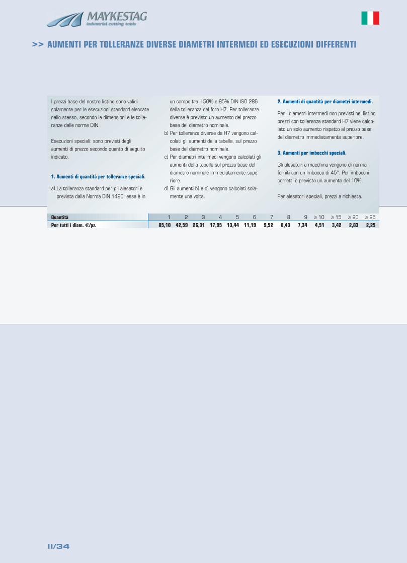
II/34
>>
I prezzi base del nostro listino sono validi
solamente per le esecuzioni standard elencate
nello stesso, secondo le dimensioni e le tolle-
ranze delle norme DIN.
Esecuzioni speciali: sono previsti degli
aumenti di prezzo secondo quanto di seguito
indicato.
1. Aumenti di quantità per tolleranze speciali.
a) La tolleranza standard per gli alesatori è
prevista dalla Norma DIN 1420: essa è in
un campo tra il 50% e 85% DIN ISO 286
della tolleranza del foro H7. Per tolleranze
diverse è previsto un aumento del prezzo
base del diametro nominale.
b) Per tolleranze diverse da H7 vengono cal-
colati gli aumenti della tabella, sul prezzo
base del diametro nominale.
c) Per diametri intermedi vengono calcolati gli
aumenti della tabella sul prezzo base del
diametro nominale immediatamente supe-
riore.
d) Gli aumenti b) e c) vengono calcolati sola-
mente una volta.
2. Aumenti di quantità per diametri intermedi.
Per i diametri intermedi non previsti nel listino
prezzi con tolleranza standard H7 viene calco-
lato un solo aumento rispetto al prezzo base
del diametro immediatamente superiore.
3. Aumenti per imbocchi speciali.
Gli alesatori a macchina vengono di norma
forniti con un Imbocco di 45°. Per imbocchi
corretti è previsto un aumento del 10%.
Per alesatori speciali, prezzi a richiesta.
Quantità 1 2 3 4 5 6 7 8 9 ≥ 10 ≥ 15 ≥ 20 ≥ 25
Per tutti i diam. €/pz. 85,10 42,59 26,31 17,95 13,44 11,19 9,52 8,43 7,34 4,51 3,42 2,83 2,25
AUMENTI PER TOLLERANZE DIVERSE DIAMETRI INTERMEDI ED ESECUZIONI DIFFERENTI
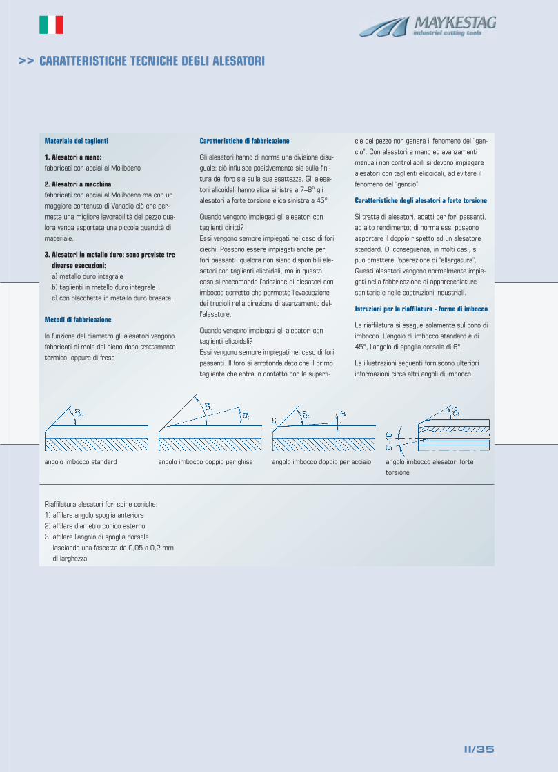
II/35
>> CARATTERISTICHE TECNICHE DEGLI ALESATORI
Materiale dei taglienti
1. Alesatori a mano: fabbricati con acciai al Molibdeno
2. Alesatori a macchinafabbricati con acciai al Molibdeno ma con un
maggiore contenuto di Vanadio ciò che per-
mette una migliore lavorabilità del pezzo qua-
lora venga asportata una piccola quantità di
materiale.
3. Alesatori in metallo duro: sono previste trediverse esecuzioni:a) metallo duro integrale
b) taglienti in metallo duro integrale
c) con placchette in metallo duro brasate.
Metodi di fabbricazione
In funzione del diametro gli alesatori vengono
fabbricati di mola dal pieno dopo trattamento
termico, oppure di fresa
Caratteristiche di fabbricazione
Gli alesatori hanno di norma una divisione disu-
guale: ciò influisce positivamente sia sulla fini-
tura del foro sia sulla sua esattezza. Gli alesa-
tori elicoidali hanno elica sinistra a 7–8° gli
alesatori a forte torsione elica sinistra a 45°
Quando vengono impiegati gli alesatori con
taglienti diritti?
Essi vengono sempre impiegati nel caso di fori
ciechi. Possono essere impiegati anche per
fori passanti, qualora non siano disponibili ale-
satori con taglienti elicoidali, ma in questo
caso si raccomanda l’adozione di alesatori con
imbocco corretto che permette l’evacuazione
dei trucioli nella direzione di avanzamento del-
l’alesatore.
Quando vengono impiegati gli alesatori con
taglienti elicoidali?
Essi vengono sempre impiegati nel caso di fori
passanti. Il foro si arrotonda dato che il primo
tagliente che entra in contatto con la superfi-
cie del pezzo non genera il fenomeno del “gan-
cio”. Con alesatori a mano ed avanzamenti
manuali non controllabili si devono impiegare
alesatori con taglienti elicoidali, ad evitare il
fenomeno del “gancio”
Caratteristiche degli alesatori a forte torsione
Si tratta di alesatori, adatti per fori passanti,
ad alto rendimento; di norma essi possono
asportare il doppio rispetto ad un alesatore
standard. Di conseguenza, in molti casi, si
può omettere l’operazione di “allargatura”.
Questi alesatori vengono normalmente impie-
gati nella fabbricazione di apparecchiature
sanitarie e nelle costruzioni industriali.
Istruzioni per la riaffilatura - forme di imbocco
La riaffilatura si esegue solamente sul cono di
imbocco. L’angolo di imbocco standard è di
45°, l’angolo di spoglia dorsale di 6°.
Le illustrazioni seguenti forniscono ulteriori
informazioni circa altri angoli di imbocco
Riaffilatura alesatori fori spine coniche:
1) affilare angolo spoglia anteriore
2) affilare diametro conico esterno
3) affilare l’angolo di spoglia dorsale
lasciando una fascetta da 0,05 a 0,2 mm
di larghezza.
angolo imbocco standard angolo imbocco doppio per ghisa angolo imbocco doppio per acciaio angolo imbocco alesatori forte
torsione
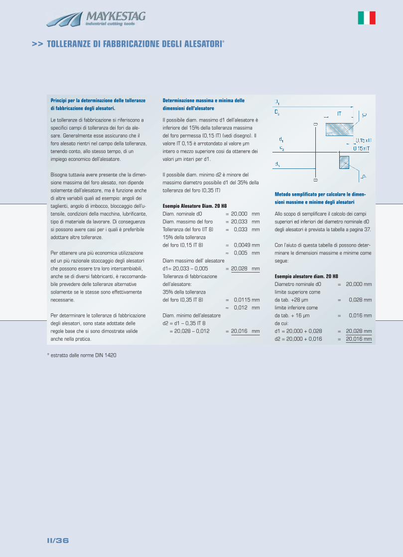
II/36
>> TOLLERANZE DI FABBRICAZIONE DEGLI ALESATORI*
Principi per la determinazione delle tolleranzedi fabbricazione degli alesatori.
Le tolleranze di fabbricazione si riferiscono a
specifici campi di tolleranza dei fori da ale-
sare. Generalmente esse assicurano che il
foro alesato rientri nel campo della tolleranza,
tenendo conto, allo stesso tempo, di un
impiego economico dell’alesatore.
Bisogna tuttavia avere presente che la dimen-
sione massima del foro alesato, non dipende
solamente dall’alesatore, ma è funzione anche
di altre variabili quali ad esempio: angoli dei
taglienti, angolo di imbocco, bloccaggio dell’u-
tensile, condizioni della macchina, lubrificante,
tipo di materiale da lavorare. Di conseguenza
si possono avere casi per i quali è preferibile
adottare altre tolleranze.
Per ottenere una più economica utilizzazione
ed un più razionale stoccaggio degli alesatori
che possono essere tra loro intercambiabili,
anche se di diversi fabbricanti, è raccomanda-
bile prevedere delle tolleranze alternative
solamente se le stesse sono effettivamente
necessarie.
Per determinare le tolleranze di fabbricazione
degli alesatori, sono state adottate delle
regole base che si sono dimostrate valide
anche nella pratica.
Determinazione massima e minima delledimensioni dell’alesatore
Il possibile diam. massimo d1 dell’alesatore è
inferiore del 15% della tolleranza massima
del foro permessa (0,15 IT) (vedi disegno). Il
valore IT 0,15 è arrotondato al valore µm
intero o mezzo superiore cosi da ottenere dei
valori µm interi per d1.
Il possibile diam. minimo d2 è minore del
massimo diametro possibile d1 del 35% della
tolleranza del foro (0,35 IT)
Esempio Alesatore Diam. 20 H8Diam. nominale d0 = 20,000 mm
Diam. massimo del foro = 20,033 mm
Tolleranza del foro (IT 8) = 0,033 mm
15% della tolleranza
del foro (0,15 IT 8) = 0,0049 mm
≈ 0,005 mm
Diam massimo dell’ alesatore
d1= 20,033 – 0,005 = 20,028 mm
Tolleranza di fabbricazione
dell’alesatore:
35% della tolleranza
del foro (0,35 IT 8) = 0,0115 mm
≈ 0,012 mm
Diam. minimo dell’alesatore
d2 = d1 – 0,35 IT 8
= 20,028 – 0,012 = 20,016 mm
Metodo semplificato per calcolare le dimen-sioni massime e minime degli alesatori
Allo scopo di semplificare il calcolo dei campi
superiori ed inferiori del diametro nominale d0
degli alesatori è prevista la tabella a pagina 37.
Con l’aiuto di questa tabella di possono deter-
minare le dimensioni massime e minime come
segue:
Esempio alesatore diam. 20 H8Diametro nominale d0 = 20,000 mm
limite superiore come
da tab. +28 µm = 0,028 mm
limite inferiore come
da tab. + 16 µm = 0,016 mm
da cui:
d1 = 20,000 + 0,028 = 20,028 mm
d2 = 20,000 + 0,016 = 20,016 mm
* estratto dalle norme DIN 1420
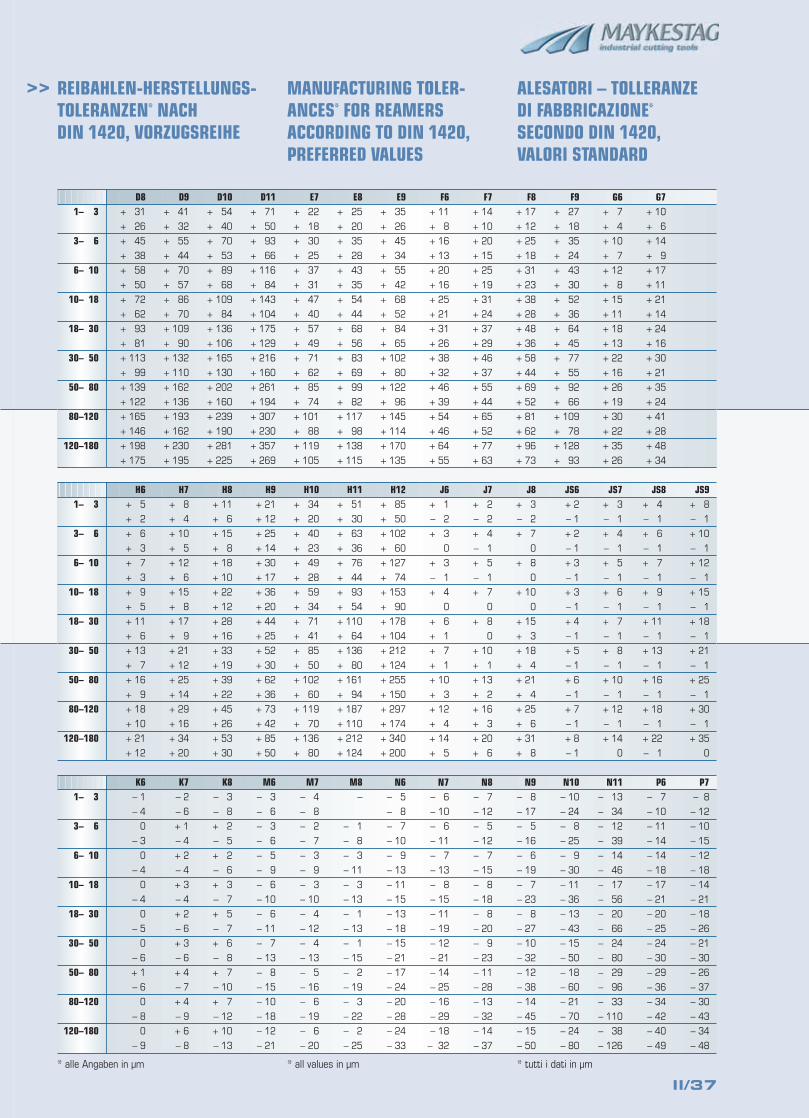
II/37
>> REIBAHLEN-HERSTELLUNGS-TOLERANZEN* NACH DIN 1420, VORZUGSREIHE
MANUFACTURING TOLER-ANCES* FOR REAMERSACCORDING TO DIN 1420,PREFERRED VALUES
ALESATORI – TOLLERANZEDI FABBRICAZIONE*
SECONDO DIN 1420,VALORI STANDARD
* alle Angaben in µm * all values in µm * tutti i dati in µm
D8 D9 D10 D11 E7 E8+ 31
+ 26
+ 45
+ 38
+ 58
+ 50
+ 72
+ 62
+ 93
+ 81
+ 113
+ 99
+ 139
+ 122
+ 165
+ 146
+ 198
+ 175
+ 41
+ 32
+ 55
+ 44
+ 70
+ 57
+ 86
+ 70
+ 109
+ 90
+ 132
+ 110
+ 162
+ 136
+ 193
+ 162
+ 230
+ 195
+ 54
+ 40
+ 70
+ 53
+ 89
+ 68
+ 109
+ 84
+ 136
+ 106
+ 165
+ 130
+ 202
+ 160
+ 239
+ 190
+ 281
+ 225
+ 71
+ 50
+ 93
+ 66
+ 116
+ 84
+ 143
+ 104
+ 175
+ 129
+ 216
+ 160
+ 261
+ 194
+ 307
+ 230
+ 357
+ 269
+ 22
+ 18
+ 30
+ 25
+ 37
+ 31
+ 47
+ 40
+ 57
+ 49
+ 71
+ 62
+ 85
+ 74
+ 101
+ 88
+ 119
+ 105
+ 25
+ 20
+ 35
+ 28
+ 43
+ 35
+ 54
+ 44
+ 68
+ 56
+ 83
+ 69
+ 99
+ 82
+ 117
+ 98
+ 138
+ 115
E9+ 35
+ 26
+ 45
+ 34
+ 55
+ 42
+ 68
+ 52
+ 84
+ 65
+ 102
+ 80
+ 122
+ 96
+ 145
+ 114
+ 170
+ 135
F6+ 11
+ 8
+ 16
+ 13
+ 20
+ 16
+ 25
+ 21
+ 31
+ 26
+ 38
+ 32
+ 46
+ 39
+ 54
+ 46
+ 64
+ 55
F7+ 14
+ 10
+ 20
+ 15
+ 25
+ 19
+ 31
+ 24
+ 37
+ 29
+ 46
+ 37
+ 55
+ 44
+ 65
+ 52
+ 77
+ 63
F8+ 17
+ 12
+ 25
+ 18
+ 31
+ 23
+ 38
+ 28
+ 48
+ 36
+ 58
+ 44
+ 69
+ 52
+ 81
+ 62
+ 96
+ 73
F9+ 27
+ 18
+ 35
+ 24
+ 43
+ 30
+ 52
+ 36
+ 64
+ 45
+ 77
+ 55
+ 92
+ 66
+ 109
+ 78
+ 128
+ 93
G6+ 7
+ 4
+ 10
+ 7
+ 12
+ 8
+ 15
+ 11
+ 18
+ 13
+ 22
+ 16
+ 26
+ 19
+ 30
+ 22
+ 35
+ 26
G7+ 10
+ 6
+ 14
+ 9
+ 17
+ 11
+ 21
+ 14
+ 24
+ 16
+ 30
+ 21
+ 35
+ 24
+ 41
+ 28
+ 48
+ 34
1– 3
3– 6
6– 10
10– 18
18– 30
30– 50
50– 80
80–120
120–180
H6 H7 H8 H9 H10 H11+ 5
+ 2
+ 6
+ 3
+ 7
+ 3
+ 9
+ 5
+ 11
+ 6
+ 13
+ 7
+ 16
+ 9
+ 18
+ 10
+ 21
+ 12
+ 8
+ 4
+ 10
+ 5
+ 12
+ 6
+ 15
+ 8
+ 17
+ 9
+ 21
+ 12
+ 25
+ 14
+ 29
+ 16
+ 34
+ 20
+ 11
+ 6
+ 15
+ 8
+ 18
+ 10
+ 22
+ 12
+ 28
+ 16
+ 33
+ 19
+ 39
+ 22
+ 45
+ 26
+ 53
+ 30
+ 21
+ 12
+ 25
+ 14
+ 30
+ 17
+ 36
+ 20
+ 44
+ 25
+ 52
+ 30
+ 62
+ 36
+ 73
+ 42
+ 85
+ 50
+ 34
+ 20
+ 40
+ 23
+ 49
+ 28
+ 59
+ 34
+ 71
+ 41
+ 85
+ 50
+ 102
+ 60
+ 119
+ 70
+ 136
+ 80
+ 51
+ 30
+ 63
+ 36
+ 76
+ 44
+ 93
+ 54
+ 110
+ 64
+ 136
+ 80
+ 161
+ 94
+ 187
+ 110
+ 212
+ 124
H12+ 85
+ 50
+ 102
+ 60
+ 127
+ 74
+ 153
+ 90
+ 178
+ 104
+ 212
+ 124
+ 255
+ 150
+ 297
+ 174
+ 340
+ 200
J6+ 1
– 2
+ 3
0
+ 3
– 1
+ 4
0
+ 6
+ 1
+ 7
+ 1
+ 10
+ 3
+ 12
+ 4
+ 14
+ 5
J7+ 2
– 2
+ 4
– 1
+ 5
– 1
+ 7
0
+ 8
0
+ 10
+ 1
+ 13
+ 2
+ 16
+ 3
+ 20
+ 6
J8+ 3
– 2
+ 7
0
+ 8
0
+ 10
0
+ 15
+ 3
+ 18
+ 4
+ 21
+ 4
+ 25
+ 6
+ 31
+ 8
JS6+ 2
– 1
+ 2
– 1
+ 3
– 1
+ 3
– 1
+ 4
– 1
+ 5
– 1
+ 6
– 1
+ 7
– 1
+ 8
– 1
JS7+ 3
– 1
+ 4
– 1
+ 5
– 1
+ 6
– 1
+ 7
– 1
+ 8
– 1
+ 10
– 1
+ 12
– 1
+ 14
0
JS8 JS9+ 4
– 1
+ 6
– 1
+ 7
– 1
+ 9
– 1
+ 11
– 1
+ 13
– 1
+ 16
– 1
+ 18
– 1
+ 22
– 1
+ 8
– 1
+ 10
– 1
+ 12
– 1
+ 15
– 1
+ 18
– 1
+ 21
– 1
+ 25
– 1
+ 30
– 1
+ 35
0
1– 3
3– 6
6– 10
10– 18
18– 30
30– 50
50– 80
80–120
120–180
K6 K7 K8 M6 M7 M8– 1
– 4
0
– 3
0
– 4
0
– 4
0
– 5
0
– 6
+ 1
– 6
0
– 8
0
– 9
– 2
– 6
+ 1
– 4
+ 2
– 4
+ 3
– 4
+ 2
– 6
+ 3
– 6
+ 4
– 7
+ 4
– 9
+ 6
– 8
– 3
– 8
+ 2
– 5
+ 2
– 6
+ 3
– 7
+ 5
– 7
+ 6
– 8
+ 7
– 10
+ 7
– 12
+ 10
– 13
– 3
– 6
– 3
– 6
– 5
– 9
– 6
– 10
– 6
– 11
– 7
– 13
– 8
– 15
– 10
– 18
– 12
– 21
– 4
– 8
– 2
– 7
– 3
– 9
– 3
– 10
– 4
– 12
– 4
– 13
– 5
– 16
– 6
– 19
– 6
– 20
–
– 1
– 8
– 3
– 11
– 3
– 13
– 1
– 13
– 1
– 15
– 2
– 19
– 3
– 22
– 2
– 25
N6– 5
– 8
– 7
– 10
– 9
– 13
– 11
– 15
– 13
– 18
– 15
– 21
– 17
– 24
– 20
– 28
– 24
– 33
N7– 6
– 10
– 6
– 11
– 7
– 13
– 8
– 15
– 11
– 19
– 12
– 21
– 14
– 25
– 16
– 29
– 18
– 32
N8– 7
– 12
– 5
– 12
– 7
– 15
– 8
– 18
– 8
– 20
– 9
– 23
– 11
– 28
– 13
– 32
– 14
– 37
N9– 8
– 17
– 5
– 16
– 6
– 19
– 7
– 23
– 8
– 27
– 10
– 32
– 12
– 38
– 14
– 45
– 15
– 50
N10– 10
– 24
– 8
– 25
– 9
– 30
– 11
– 36
– 13
– 43
– 15
– 50
– 18
– 60
– 21
– 70
– 24
– 80
N11– 13
– 34
– 12
– 39
– 14
– 46
– 17
– 56
– 20
– 66
– 24
– 80
– 29
– 96
– 33
– 110
– 38
– 126
P6– 7
– 10
– 11
– 14
– 14
– 18
– 17
– 21
– 20
– 25
– 24
– 30
– 29
– 36
– 34
– 42
– 40
– 49
P7– 8
– 12
– 10
– 15
– 12
– 18
– 14
– 21
– 18
– 26
– 21
– 30
– 26
– 37
– 30
– 43
– 34
– 48
1– 3
3– 6
6– 10
10– 18
18– 30
30– 50
50– 80
80–120
120–180


![RE 107 Sélection: Pistolet, Lance (05.2007) · 002 9645 945 8624 Joint torique 85x2,5 000 4755 760 7050 Jeu de pistons [3 - 5] 006 4755 701 5000 Vis M6x6 007 4755 709 2100 Bague](https://img.pdfslide.tips/doc/110x75/5e7cc7c3f20e1f0cb804cd5c/re-107-slection-pistolet-lance-052007-002-9645-945-8624-joint-torique-85x25.jpg)