Embed Size (px)
DESCRIPTION
Lightning protection
Citation preview
Lightning Protection System Design
Revised 5/28/14
ERICO has met the standards and requirements of the Registered Continuing Education Providers
Program. Credit earned on completion of this program will be reported to RCEPP. A certificate of
completion will be issued to each participant. As such, it does not include content that may be
deemed or construed to be an approval or endorsement by NCEES or RCEPP.”
At the end of this class you will be able to:
Understand the principle of lightning protection Understand what a lightning protection system is Understand how lightning is formed Identify the different ways to be struck by lightning Use and understand the Risk Assessment in NFPA® 780 Understand the various lightning protection codes Understand what surge protection is and how it is used Identify other types of lightning protection systems
NFPA is a registered trademark of National Fire Protection Association, Inc.
Learning Objectives
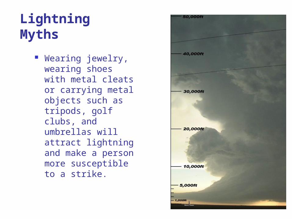
Wearing jewelry, wearing shoes with metal cleats or carrying metal objects such as tripods, golf clubs, and umbrellas will attract lightning and make a person more susceptible to a strike.
Lightning Myths
Lightning Video
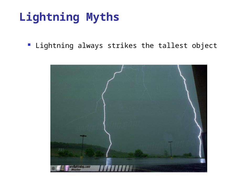
Lightning always strikes the tallest object
Lightning Myths
Lightning strikes can occur either at the beginning or end of a storm
The average lightning strike is six miles long Lightning reaches 50,000 degrees Fahrenheit, fours times as hot
as the sun's surface Voltage in a cloud-to-ground strike is 100 million to 1 billion
volts Around the earth there are 100 lightning strikes per second, or
8,640,000 times a day There are approximately 100,000 thunderstorms in the U.S.
each year
Lightning Facts
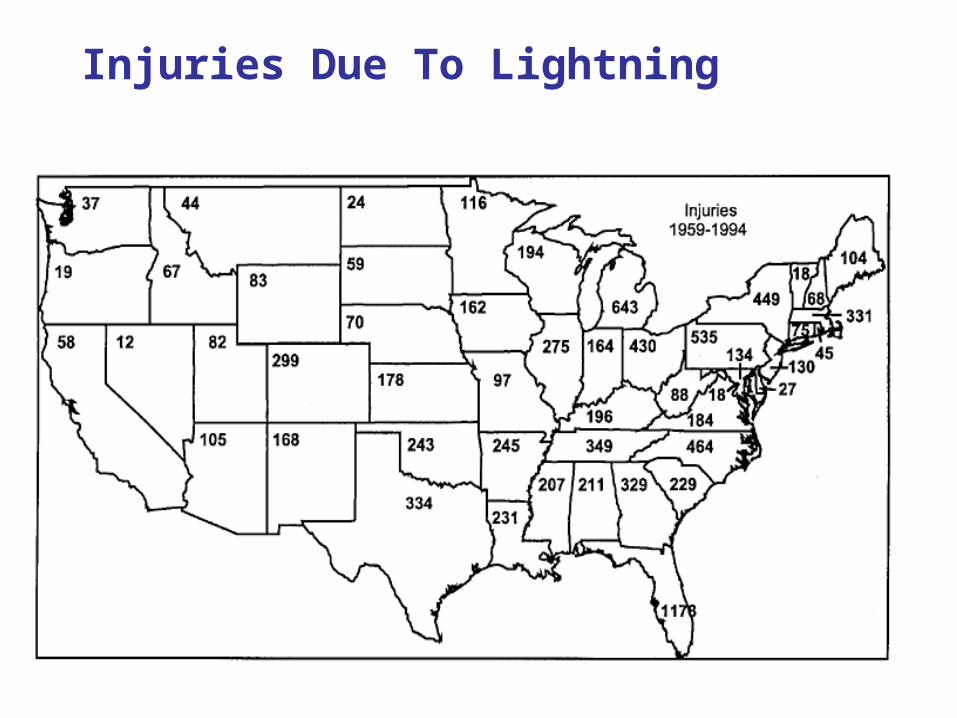
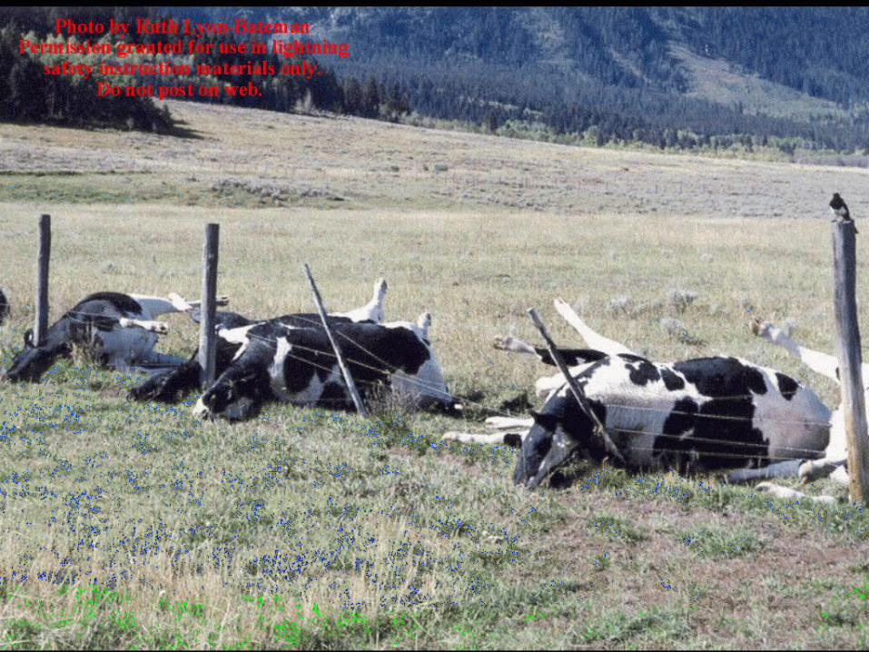
Injuries Due To Lightning
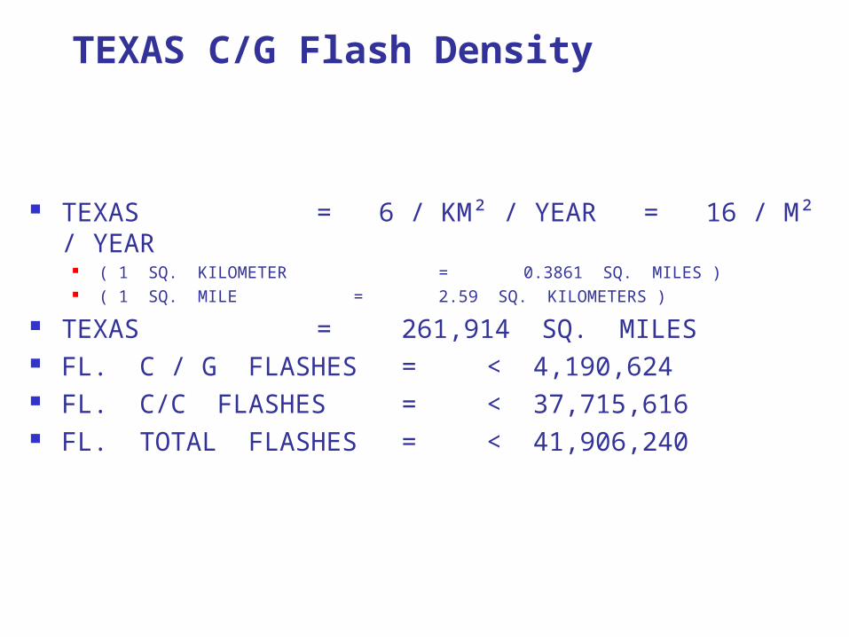
TEXAS C/G Flash Density
TEXAS = 6 / KM² / YEAR = 16 / M² / YEAR ( 1 SQ. KILOMETER = 0.3861 SQ. MILES ) ( 1 SQ. MILE = 2.59 SQ. KILOMETERS )
TEXAS = 261,914 SQ. MILES FL. C / G FLASHES = < 4,190,624 FL. C/C FLASHES = < 37,715,616 FL. TOTAL FLASHES = < 41,906,240
/ / / / / / / / / / / / / / / / / / / / / /
/ / / / / / / / / / / / / / / / / / / / / /
/ / / / / / / / / / / / / / / / / / / / / /
/ / / / / / / / / / / / / / / / / / / / / /
/ / / / / / / / / / / / / / / / / / / / / /
/ / / / / / / / / / / / / / / / / / / / / /
/ / / / / / / / / / / / / / / / / / / / / /
/ / / / / / / / / / / / / / / / / / / / / /


/ / / / / / / / / / / / / / / / / / / / / /
/ / / / / / / / / / / / / / / / / / / / / /
/ / / / / / / / / / / / / / / / / / / / / /
/ / / / / / / / / / / / / / / / / / / / / /
/ / / / / / / / / / / / / / / / / / / / / /
/ / / / / / / / / / / / / / / / / / / / / /
/ / / / / / / / / / / / / / / / / / / / / /
/ / / / / / / / / / / / / / / / / / / / / /
+ + + + + + + + + + + + + + + +
+ + + + + + + + + + + + + + + + + + + + - + - + - + - + - + - + - + - +
- - - - - - - - - - -
- -
+ + + + + + + + + + + + + + + +
+ + + + + + + + + + + + + + + + + + + + - + - + - + - + - + - + - + - +
- - - - - - - - - - -
- -

/ / / / / / / / / / / / / / / / / / / / / /
/ / / / / / / / / / / / / / / / / / / / / /
/ / / / / / / / / / / / / / / / / / / / / /
/ / / / / / / / / / / / / / / / / / / / / /
/ / / / / / / / / / / / / / / / / / / / / /
/ / / / / / / / / / / / / / / / / / / / / /
/ / / / / / / / / / / / / / / / / / / / / /
/ / / / / / / / / / / / / / / / / / / / / /
+ + + + + + + + + + + + + + + +
+ + + + + + + + + + + + + + + + + + + + - + - + - + - + - + - + - + - +
- - - - - - - - - - -
- -
+ + + + + + + + + + + + + + + +
+ + + + + + + + + + + + + + + + + + + + - + - + - + - + - + - + - + - +
- - - - - - - - - - -
- -
- - + + + + + + + + + + + + - - - -
+ + + + +
/ / / / / / / / / / / / / / / / / / / / / /
/ / / / / / / / / / / / / / / / / / / / / /
/ / / / / / / / / / / / / / / / / / / / / /
/ / / / / / / / / / / / / / / / / / / / / /
/ / / / / / / / / / / / / / / / / / / / / /
/ / / / / / / / / / / / / / / / / / / / / /
/ / / / / / / / / / / / / / / / / / / / / /
/ / / / / / / / / / / / / / / / / / / / / /
+ + + + + + + + + + + + + + + +
+ + + + + + + + + + + + + + + + + + + + - + - + - + - + - + - + - + - +
- - - - - - - - - - -
- - + + + + + + + + + + + + - - - -
- -+ + + + +
+ + + + + + + + + + + + + + + + + + + + + + + + + + + + + + + + + +
+ + + + + + + + + + + + + + + + + + + + + + + + + + + + + + + + + +
+ + + + + + + + + + + + + + + + + + + + + + + + + + + + + + + + + +

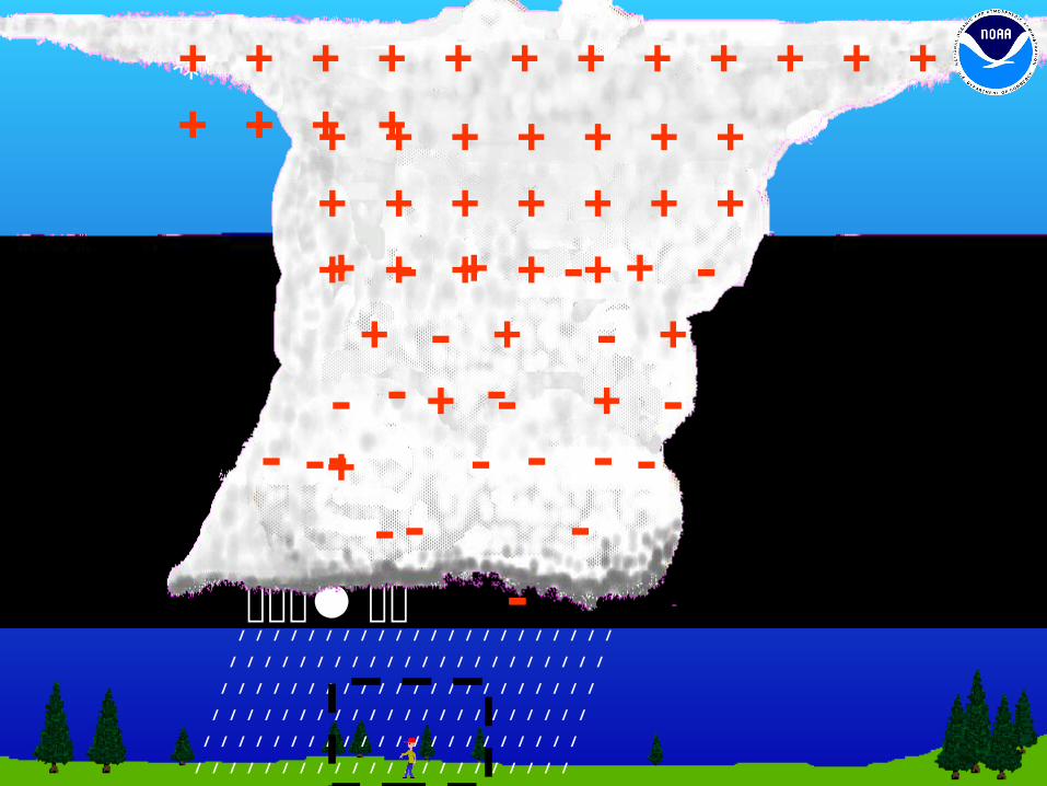
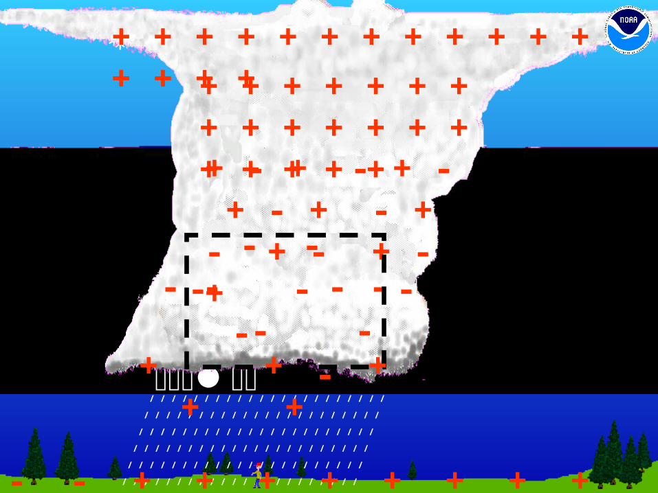
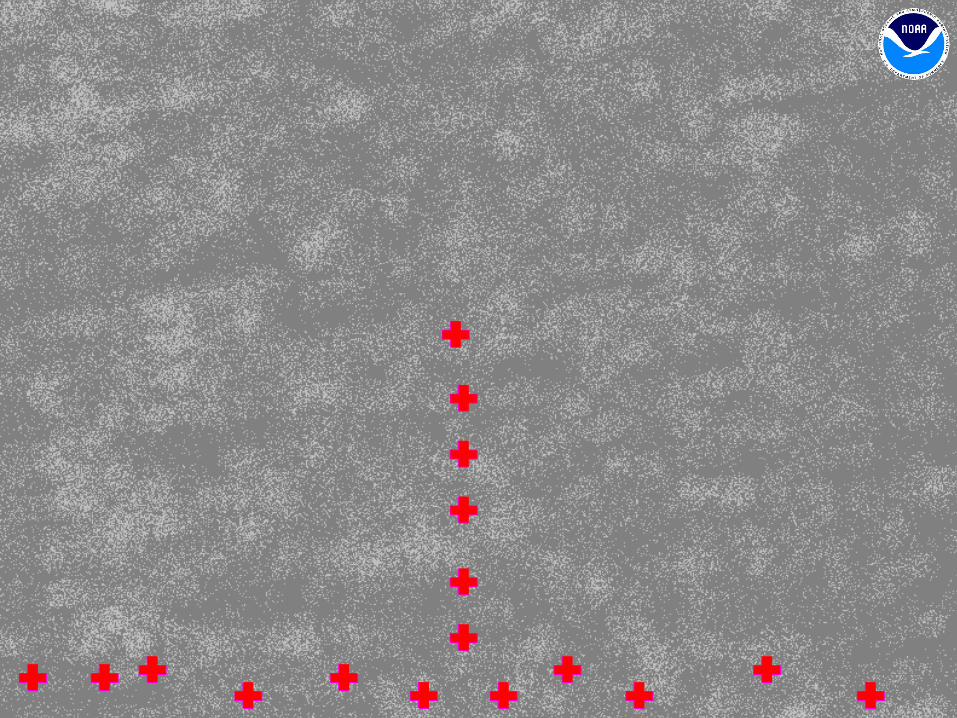
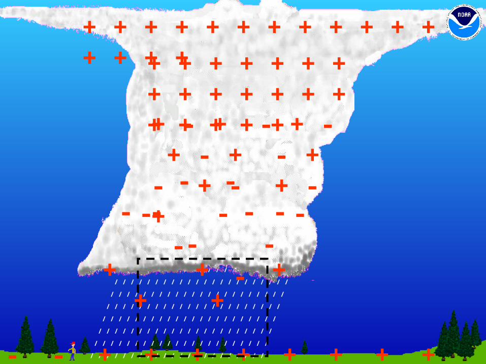
Positive Lightning
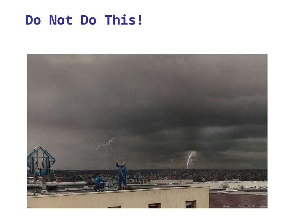
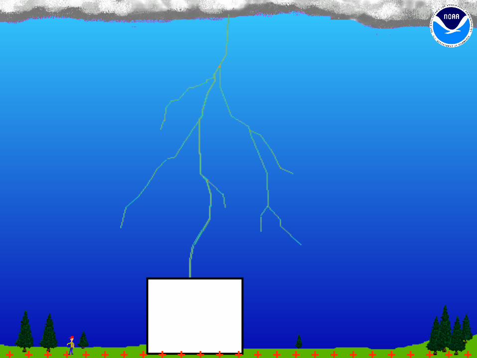
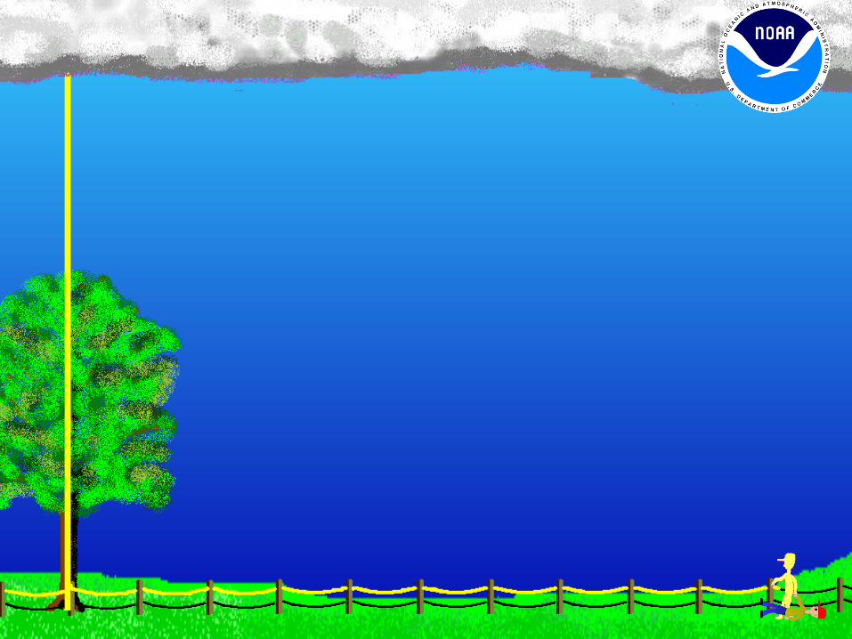
Do Not Do This!
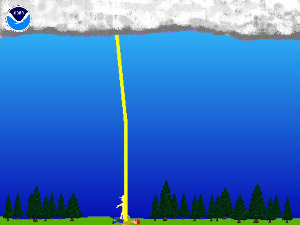
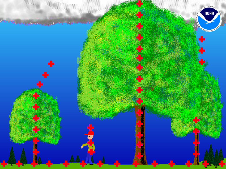
Direct strike Side flash/splash Ground current/step potential Conduction through metal
Why people are struck by lightning
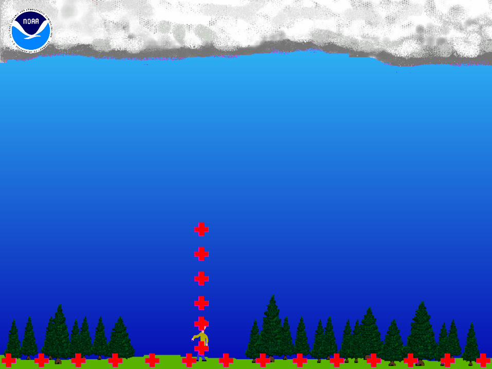
Direct Strike
Most dangerous but fairly uncommon
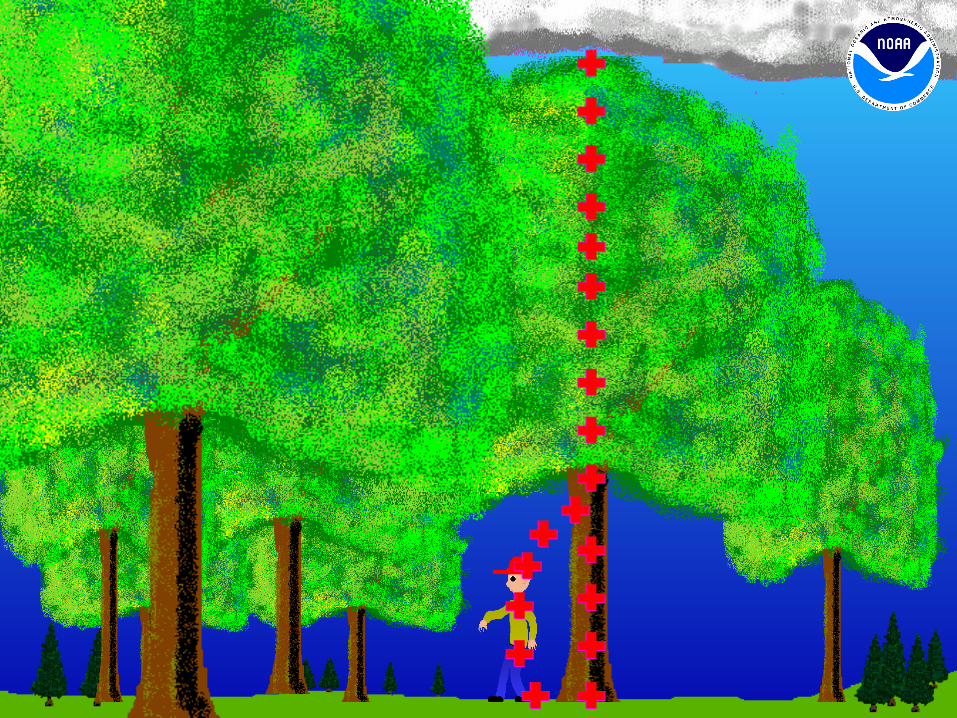
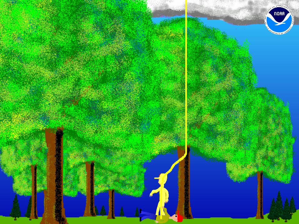
Side Flash/ Side Splash
Common for people standing under trees
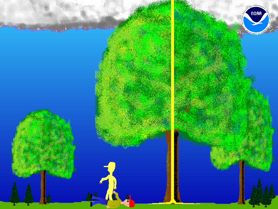
Ground Current/ Step Voltage
Fairly common


ConductionThrough metal wires or
surfaces
Fairly common especially indoors
Lightning Videos
Is related to: The lightning threat. People’s behavior when thunderstorms are nearby.
The Risk Of Being Struck By Lightening
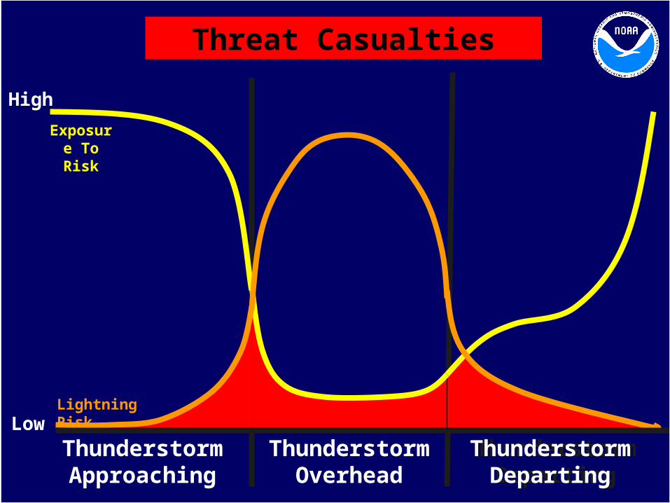
Lightning Risk
Exposure To Risk
Thunderstorm Approaching
Thunderstorm Overhead
Thunderstorm Departing
Thunderstorm Overhead
Thunderstorm Departing
Low
High
Threat Casualties
Reducing casualties: Before the storm
If the sky looks threatening, or if you hear thunder, GO TO A SAFE SHELTER IMMEDIATELY!
During the storm Avoid contact with phones, electrical equipment,
plumbing and stay away from doors and windows. After the storm
After the last rumble of thunder, wait 30 minutes before going back out side.
The Risk Of Being Struck By Lightening
Safety Objective: To reduce the number of casualties by changing people’s
behavior around thunderstorms.
The Risk Of Being Struck By Lightening

Lightning Risk
Exposure To Risk
Thunderstorm ApproachingThunderstorm Approaching
Thunderstorm Overhead
Thunderstorm Departing
Thunderstorm Overhead
Thunderstorm Departing
Low
High
Safety Objective

Commercial/IndustrialNational Fire Protection Assoc. # 780Underwriters’ Laboratories # 96ALightning Protection Institute # 175
UtilityIEEE 998 – Direct Lightning Stroke Shielding for Substations.
Lightning Protection Codes
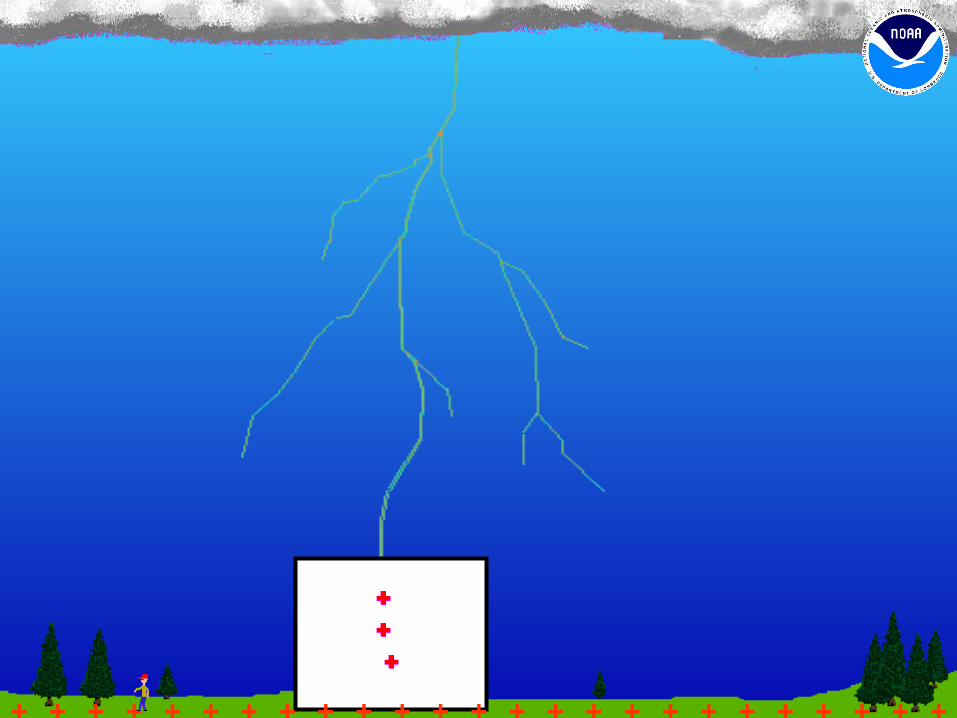
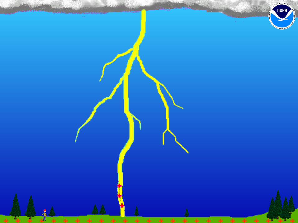
What is a lightning protection system?
A lightning protection system is a passive means of preventing property damage from the effects of a lightning strike. It works by providing the electric charge produced by the clouds a path of least resistance to the ground. There are four main parts of a properly installed lightning protection system: air terminals, cable, copper clad ground rods, and surge suppressors.
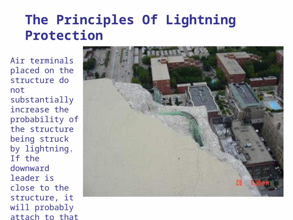
The Principles Of Lightning Protection
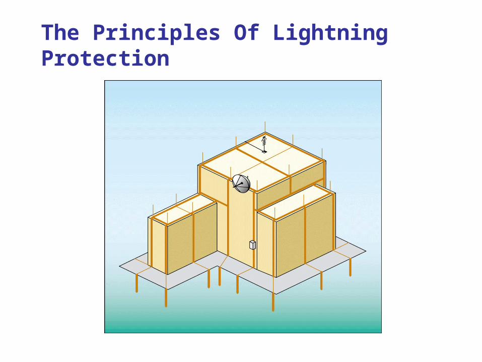
The Principles Of Lightning Protection
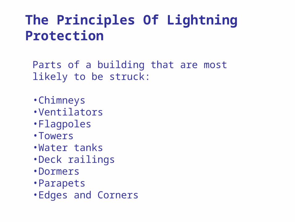
Parts of a building that are most likely to be struck:
•Chimneys•Ventilators•Flagpoles•Towers•Water tanks•Deck railings•Dormers•Parapets•Edges and Corners
The Principles Of Lightning Protection
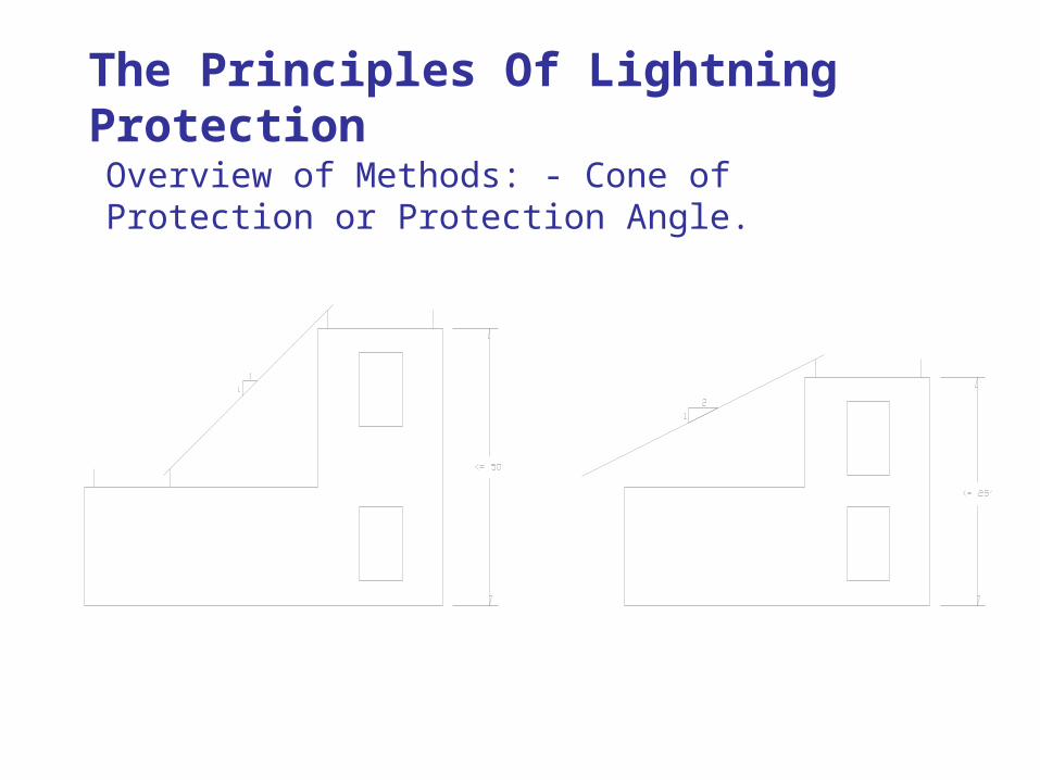
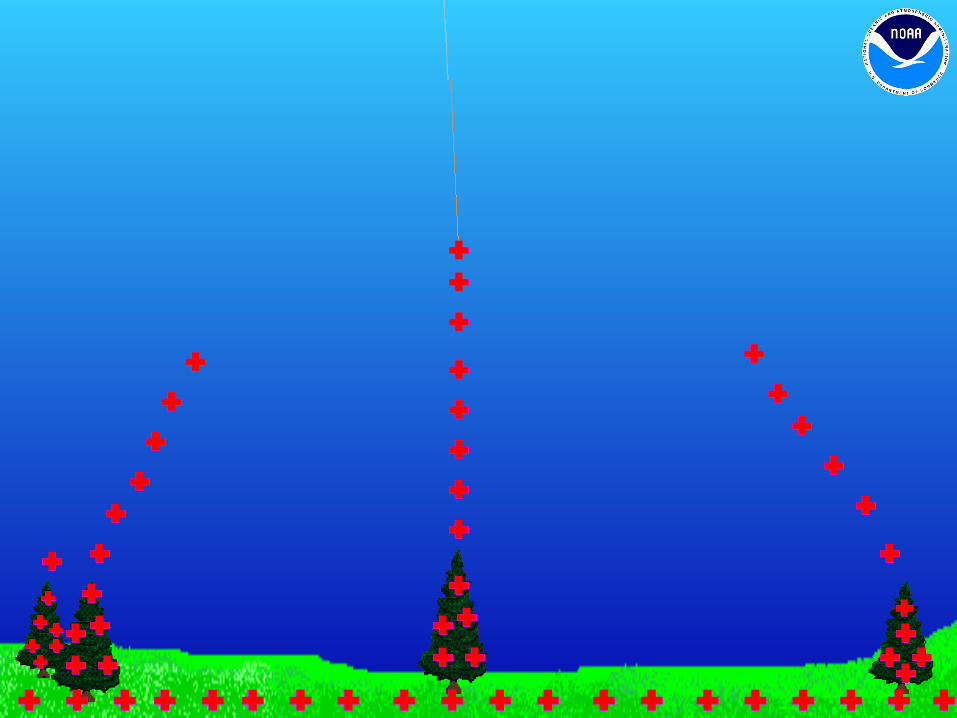
Overview of Methods: - Cone of Protection or Protection Angle.
The Principles Of Lightning Protection
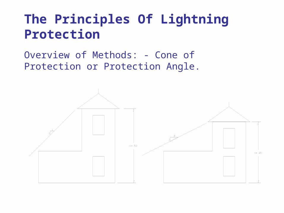
Overview of Methods: - Cone of Protection or Protection Angle.
The Principles Of Lightning Protection
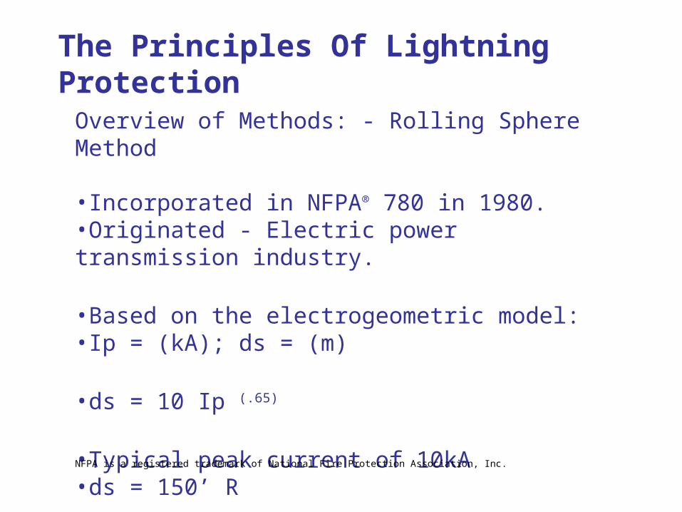
Overview of Methods: - Rolling Sphere Method
•Incorporated in NFPA® 780 in 1980.•Originated - Electric power transmission industry.
•Based on the electrogeometric model:•Ip = (kA); ds = (m)
•ds = 10 Ip (.65)
•Typical peak current of 10kA•ds = 150’ R
The Principles Of Lightning Protection
NFPA is a registered trademark of National Fire Protection Association, Inc.
Overview of Methods: - Rolling Sphere Method
150’ R – This is the distance at which the downward leader results in the initiation of an upward leader from the structure.
Peak currents below 5kA and 7kA are not common. 10kA peak current represents 91% of all lightning events.
The Principles Of Lightning Protection
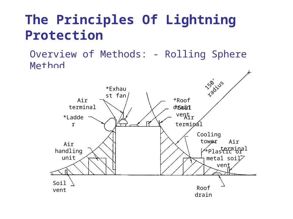
Overview of Methods: - Rolling Sphere Method
Soil vent Roof drain
*Plastic or metal soil vent
Air terminalCooling tower
Air terminal
Air terminal
*Soil vent*Roof drain
*Exhaust fan
*Ladder
Air handling unit
150’
radiu
s
The Principles Of Lightning Protection
Overview of Methods: - Rolling Sphere Method
Advantages: Easy to apply, even to buildings with complicated shapes.
Limitations: It assigns an equal leader initiation ability to all contact points on the structure. So, it cannot distinguish between likely and unlikely contact points. Could strike the corner of the building rather than the vertical flat surface halfway down the side of the building.
The Principles Of Lightning Protection
The Principles Of Lightning Protection
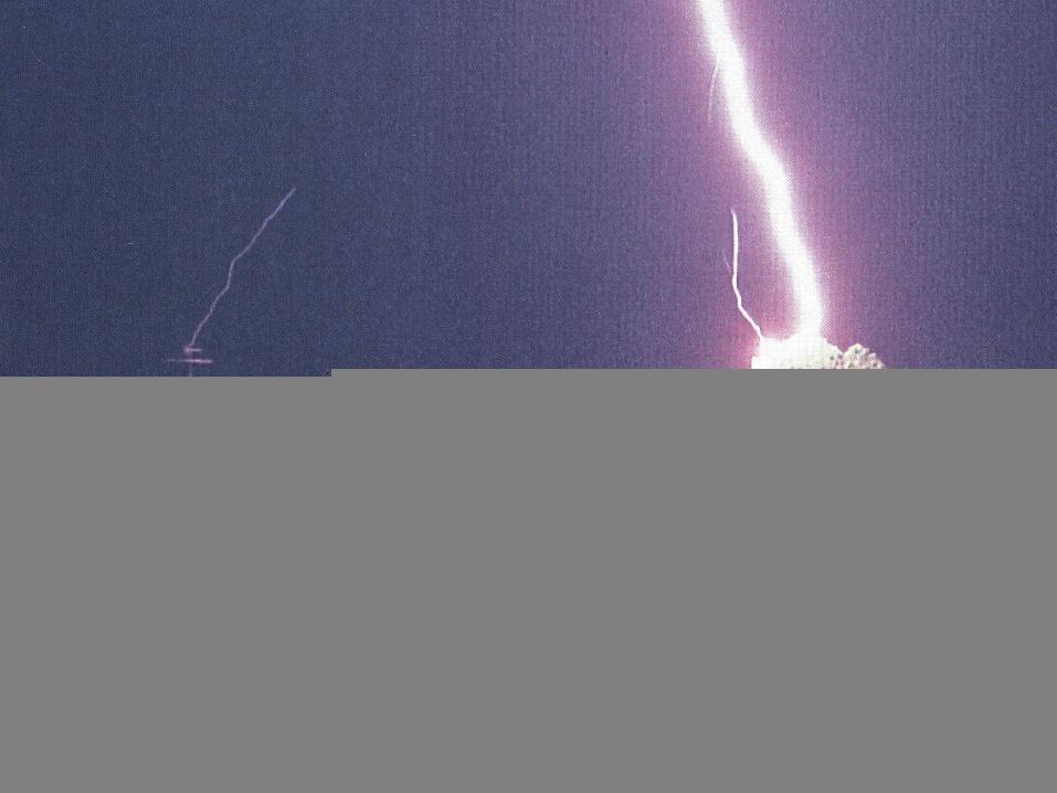
Air terminals placed on the structure do not substantially increase the probability of the structure being struck by lightning. If the downward leader is close to the structure, it will probably attach to that structure anyway.
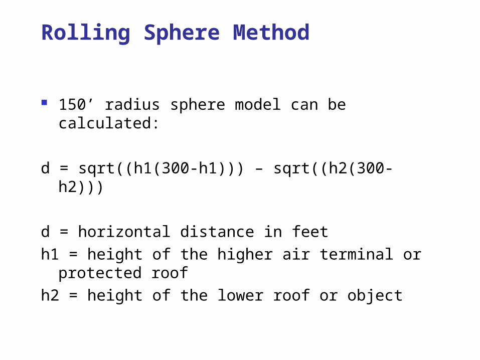
150’ radius sphere model can be calculated:
d = sqrt((h1(300-h1))) – sqrt((h2(300-h2)))
d = horizontal distance in feeth1 = height of the higher air terminal or protected roofh2 = height of the lower roof or object
Rolling Sphere Method
Installations can be expensive Coverage area of any one air terminal is small Maintenance/Repair
Disadvantages of Conventional Lightning Protection Systems
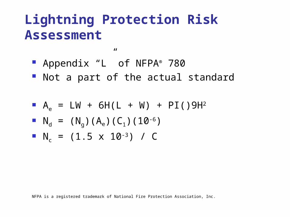
Appendix “L” of NFPA® 780 Not a part of the actual standard
Ae = LW + 6H(L + W) + PI()9H2
Nd = (Ng)(Ae)(C1)(10-6) Nc = (1.5 x 10⁻³) / C
Lightning Protection Risk Assessment
NFPA is a registered trademark of National Fire Protection Association, Inc.
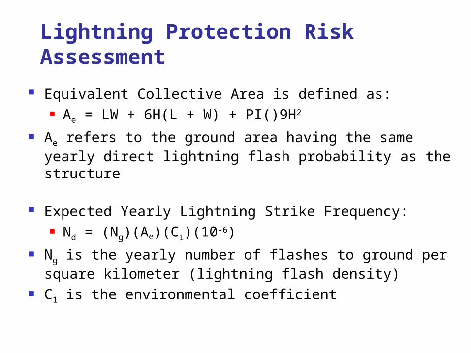
Equivalent Collective Area is defined as: Ae = LW + 6H(L + W) + PI()9H2
Ae refers to the ground area having the same yearly direct lightning flash probability as the structure
Expected Yearly Lightning Strike Frequency: Nd = (Ng)(Ae)(C1)(10-6)
Ng is the yearly number of flashes to ground per square kilometer (lightning flash density)
C1 is the environmental coefficient
Lightning Protection Risk Assessment
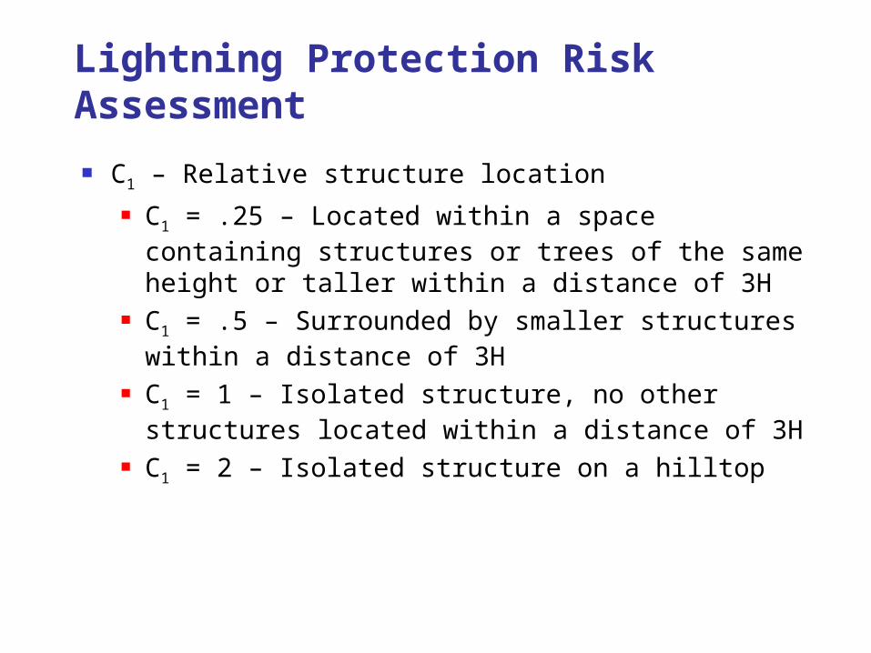
C1 – Relative structure location C1 = .25 – Located within a space containing structures
or trees of the same height or taller within a distance of 3H
C1 = .5 – Surrounded by smaller structures within a distance of 3H
C1 = 1 – Isolated structure, no other structures located within a distance of 3H
C1 = 2 – Isolated structure on a hilltop
Lightning Protection Risk Assessment
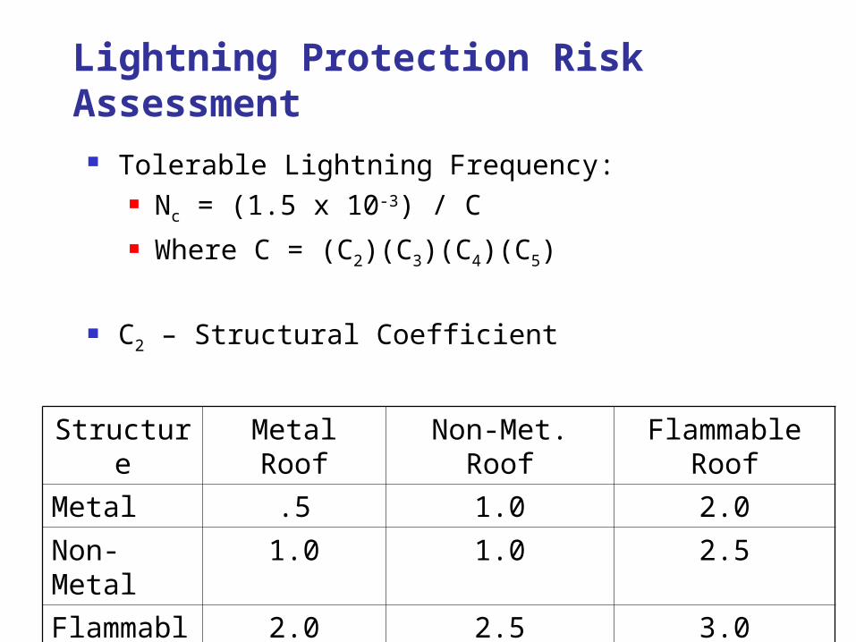
Tolerable Lightning Frequency: Nc = (1.5 x 10⁻³) / C Where C = (C2)(C3)(C4)(C5)
C2 – Structural Coefficient
Structure Metal Roof Non-Met. Roof Flammable RoofMetal .5 1.0 2.0Non-Metal 1.0 1.0 2.5Flammable 2.0 2.5 3.0
Lightning Protection Risk Assessment
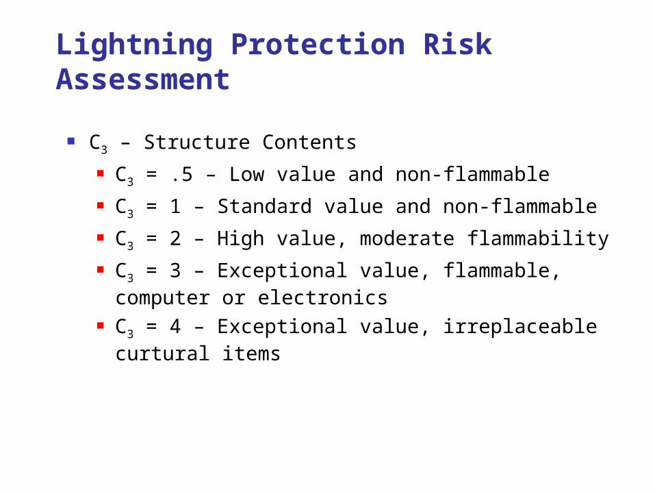
C3 – Structure Contents C3 = .5 – Low value and non-flammable C3 = 1 – Standard value and non-flammable C3 = 2 – High value, moderate flammability C3 = 3 – Exceptional value, flammable, computer or
electronics C3 = 4 – Exceptional value, irreplaceable curtural items
Lightning Protection Risk Assessment
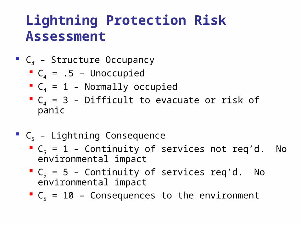
C4 – Structure Occupancy C4 = .5 – Unoccupied C4 = 1 – Normally occupied C4 = 3 – Difficult to evacuate or risk of panic
C5 – Lightning Consequence C5 = 1 – Continuity of services not req’d. No environmental
impact C5 = 5 – Continuity of services req’d. No environmental
impact C5 = 10 – Consequences to the environment
Lightning Protection Risk Assessment
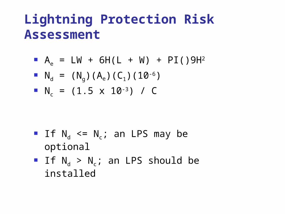
Ae = LW + 6H(L + W) + PI()9H2
Nd = (Ng)(Ae)(C1)(10-6) Nc = (1.5 x 10⁻³) / C
If Nd <= Nc; an LPS may be optional If Nd > Nc; an LPS should be installed
Lightning Protection Risk Assessment
Spreadsheet Example
Lightning Protection Risk Assessment
Owner Insurance Military Risk Assessment FL Building Code
Lightning Protection Risk Assessment
First adopted in 1904
NFPA® 780-2014
NFPA is a registered trademark of National Fire Protection Association, Inc.
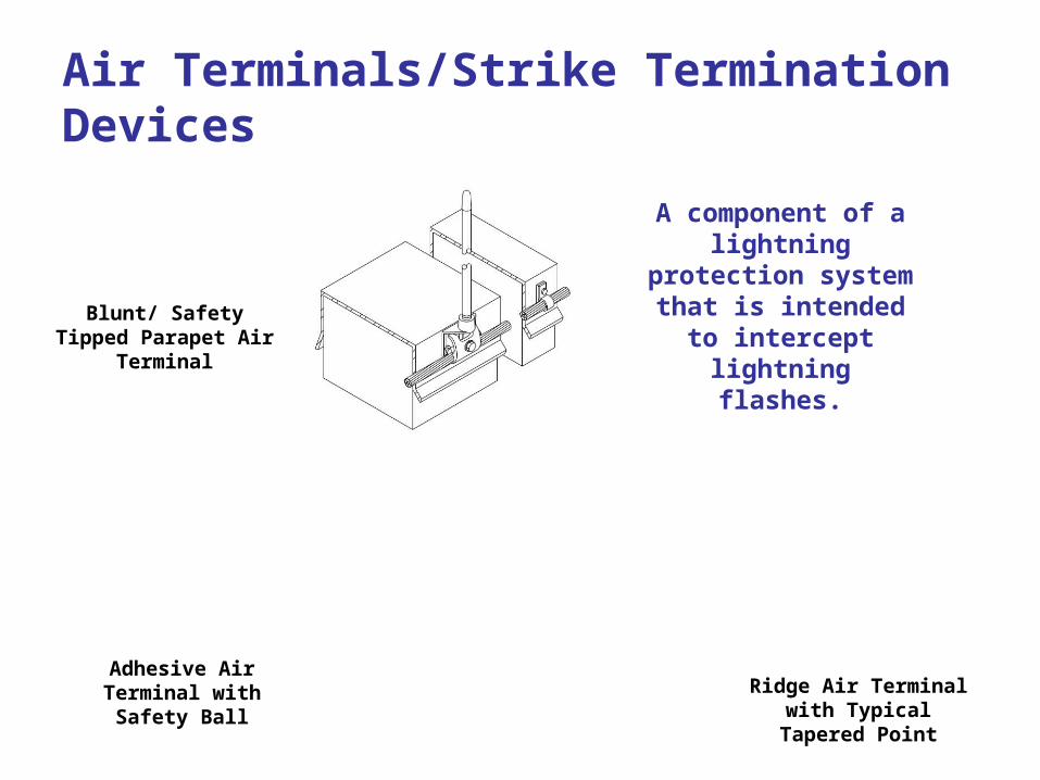
Blunt/ Safety Tipped Parapet Air Terminal
Ridge Air Terminal with Typical Tapered Point
Adhesive Air Terminal with Safety Ball
A component of a lightning protection
system that is intended to intercept lightning
flashes.
Air Terminals/Strike Termination Devices
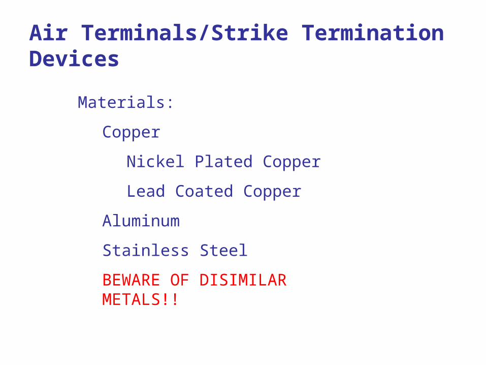
Materials:
Copper
Nickel Plated Copper
Lead Coated Copper
Aluminum
Stainless Steel
BEWARE OF DISIMILAR METALS!!
Air Terminals/Strike Termination Devices
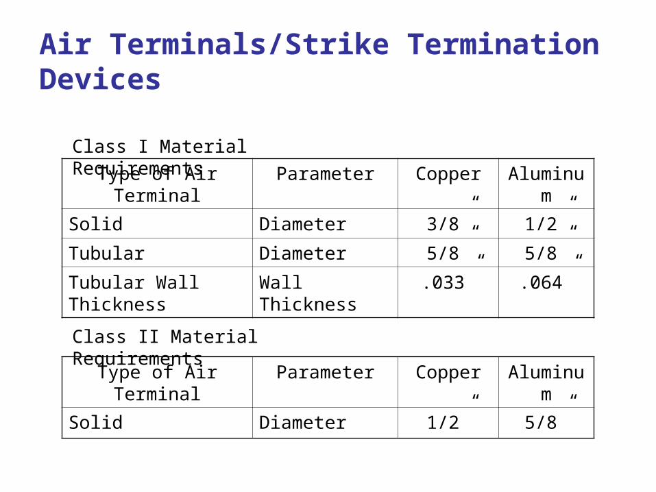
Type of Air Terminal Parameter Copper Aluminum
Solid Diameter 3/8” 1/2”
Tubular Diameter 5/8” 5/8”
Tubular Wall Thickness Wall Thickness .033” .064”
Type of Air Terminal Parameter Copper Aluminum
Solid Diameter 1/2” 5/8”
Class I Material Requirements
Class II Material Requirements
Air Terminals/Strike Termination Devices
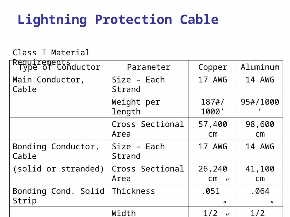
Type of Conductor Parameter Copper Aluminum
Main Conductor, Cable Size – Each Strand 17 AWG 14 AWG
Weight per length 187#/1000’ 95#/1000’
Cross Sectional Area 57,400 cm 98,600 cm
Bonding Conductor, Cable Size – Each Strand 17 AWG 14 AWG
(solid or stranded) Cross Sectional Area 26,240 cm 41,100 cm
Bonding Cond. Solid Strip Thickness .051” .064
Width 1/2” 1/2”
Thickness .051” .064
Cross Sectional Area 57,400 cm 98,600 cm
Class I Material Requirements
Lightning Protection Cable
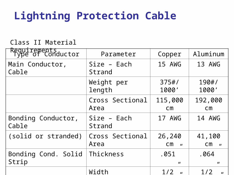
Type of Conductor Parameter Copper Aluminum
Main Conductor, Cable Size – Each Strand 15 AWG 13 AWG
Weight per length 375#/1000’ 190#/1000’
Cross Sectional Area 115,000 cm 192,000 cm
Bonding Conductor, Cable Size – Each Strand 17 AWG 14 AWG
(solid or stranded) Cross Sectional Area 26,240 cm 41,100 cm
Bonding Cond. Solid Strip Thickness .051” .064”
Width 1/2” 1/2”
Thickness .064” .1026”
Cross Sectional Area 115,000 cm 192,000 cm
Class II Material Requirements
Lightning Protection Cable
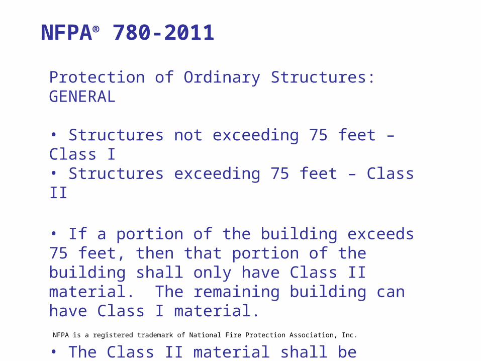
Protection of Ordinary Structures: GENERAL
• Structures not exceeding 75 feet – Class I• Structures exceeding 75 feet – Class II
• If a portion of the building exceeds 75 feet, then that portion of the building shall only have Class II material. The remaining building can have Class I material.
• The Class II material shall be extended to ground level and interconnected with the balance of the system.
NFPA® 780-2011
NFPA is a registered trademark of National Fire Protection Association, Inc.
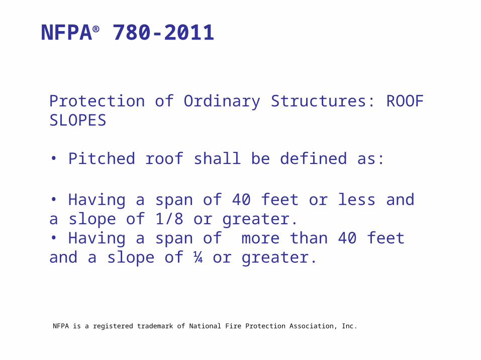
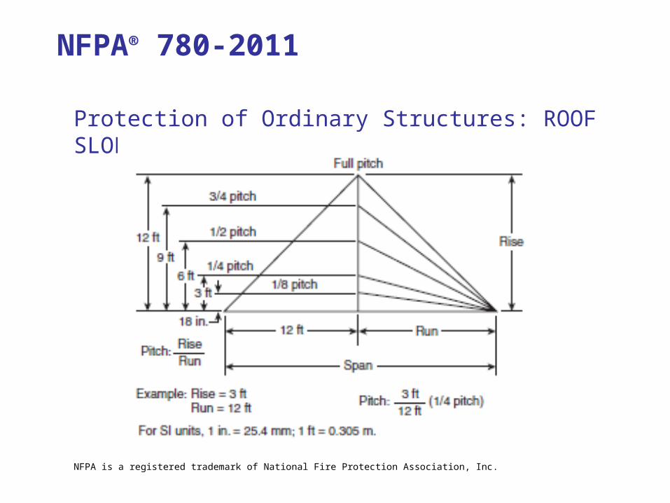
Protection of Ordinary Structures: ROOF SLOPES
• Pitched roof shall be defined as:
• Having a span of 40 feet or less and a slope of 1/8 or greater.• Having a span of more than 40 feet and a slope of ¼ or greater.
NFPA® 780-2011
NFPA is a registered trademark of National Fire Protection Association, Inc.
Protection of Ordinary Structures: ROOF SLOPES
NFPA® 780-2011
NFPA is a registered trademark of National Fire Protection Association, Inc.
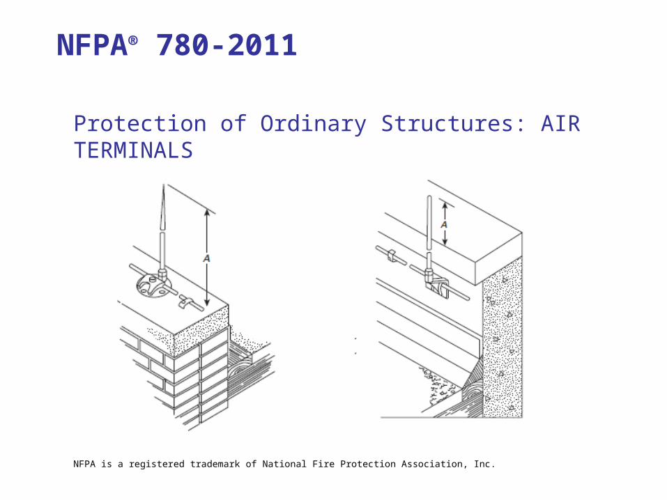
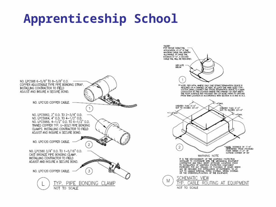
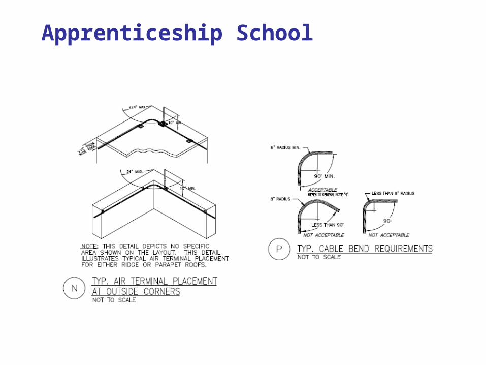
Protection of Ordinary Structures: AIR TERMINALS
NFPA® 780-2011
NFPA is a registered trademark of National Fire Protection Association, Inc.
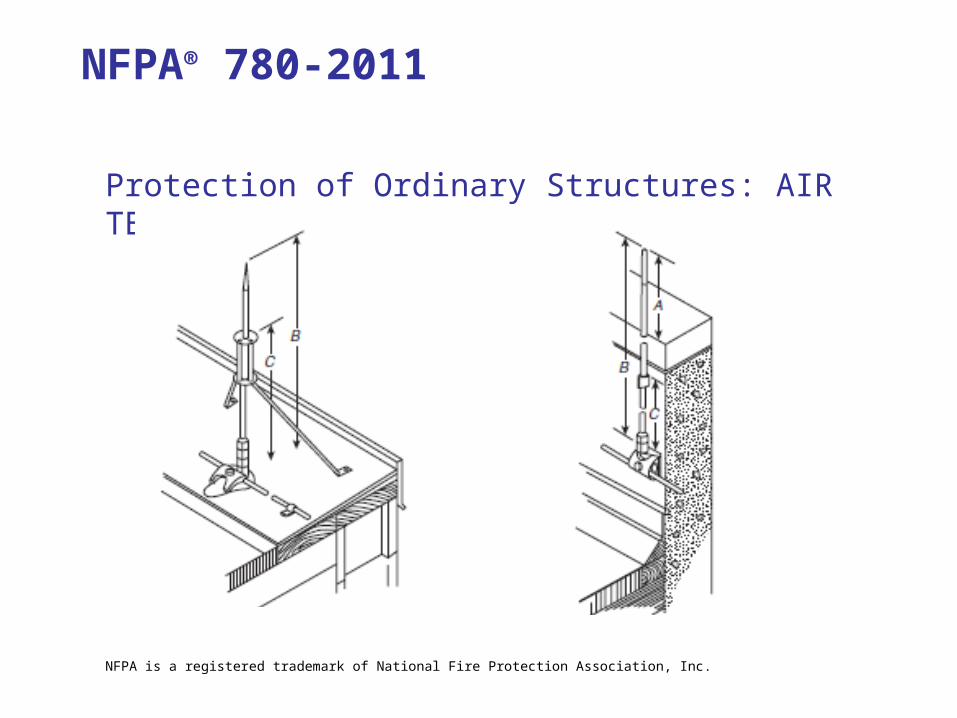
Protection of Ordinary Structures: AIR TERMINALS
NFPA® 780-2011
NFPA is a registered trademark of National Fire Protection Association, Inc.
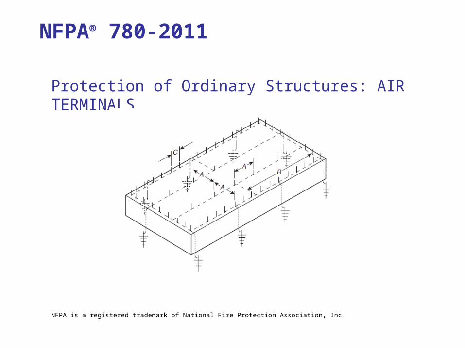
Protection of Ordinary Structures: AIR TERMINALS
NFPA® 780-2011
NFPA is a registered trademark of National Fire Protection Association, Inc.
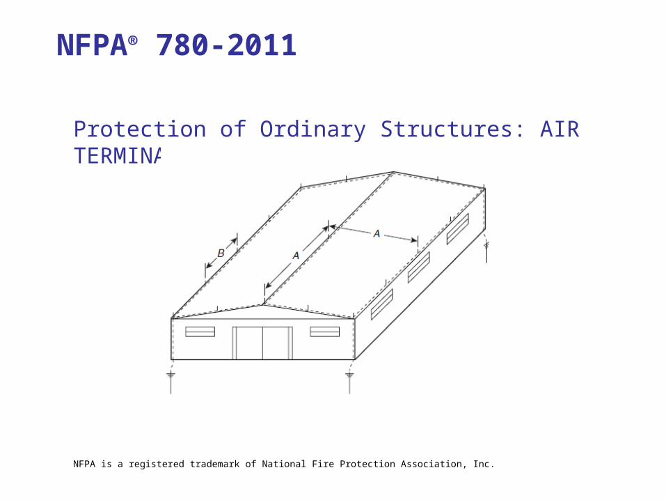
Protection of Ordinary Structures: AIR TERMINALS
NFPA® 780-2011
NFPA is a registered trademark of National Fire Protection Association, Inc.
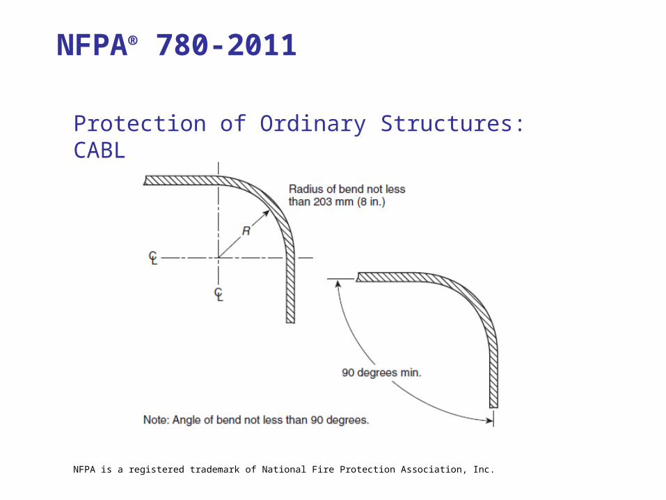
Protection of Ordinary Structures: CABLE BENDS
NFPA® 780-2011
NFPA is a registered trademark of National Fire Protection Association, Inc.
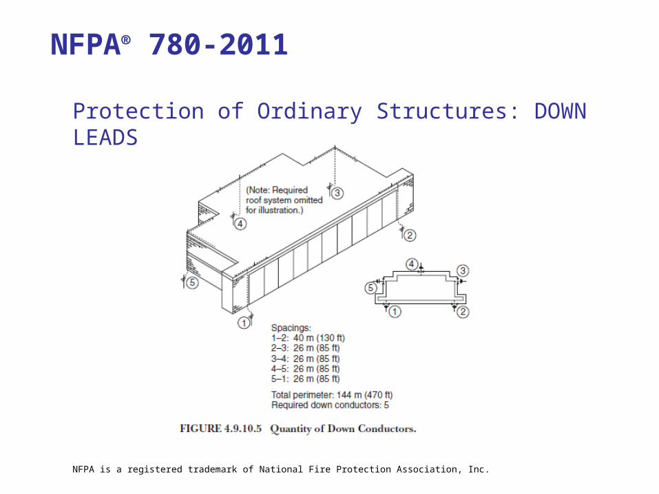
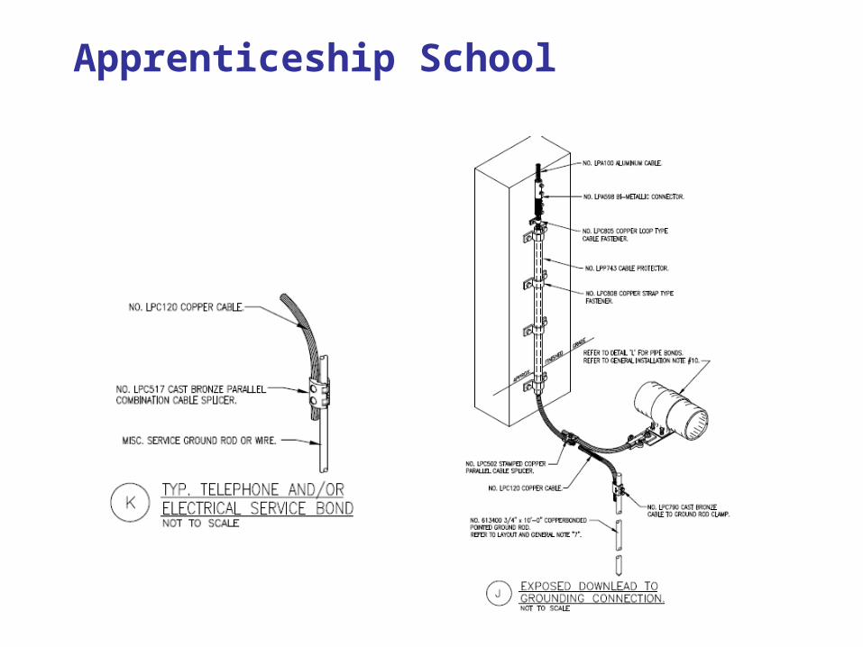
Protection of Ordinary Structures: DOWN LEADS
NFPA® 780-2011
NFPA is a registered trademark of National Fire Protection Association, Inc.
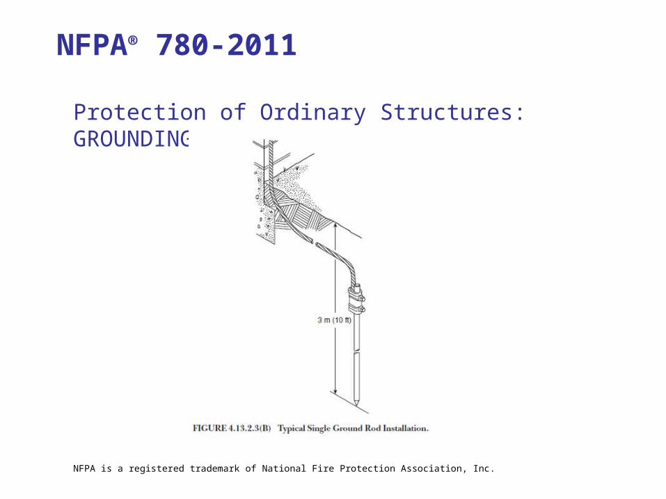
Protection of Ordinary Structures: GROUNDING
NFPA® 780-2011
NFPA is a registered trademark of National Fire Protection Association, Inc.
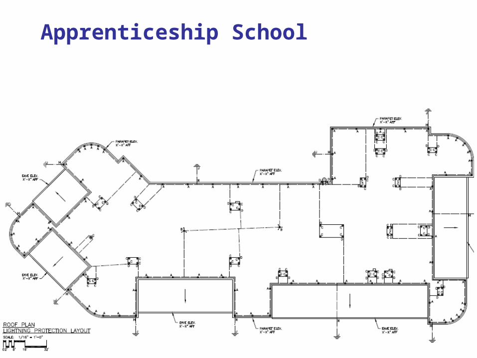
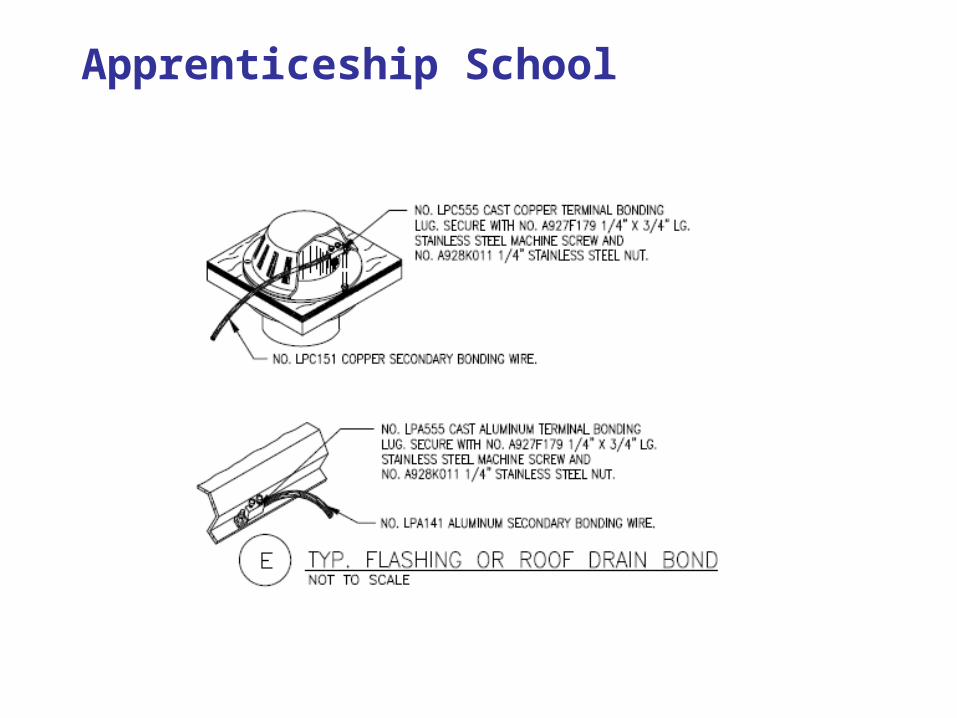
Apprenticeship School
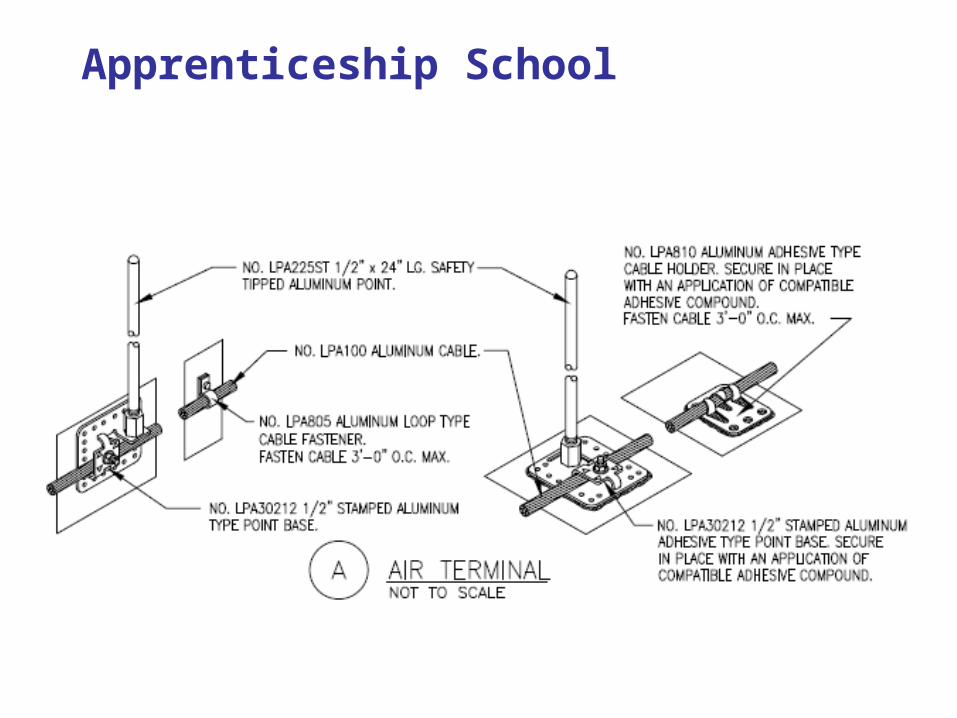
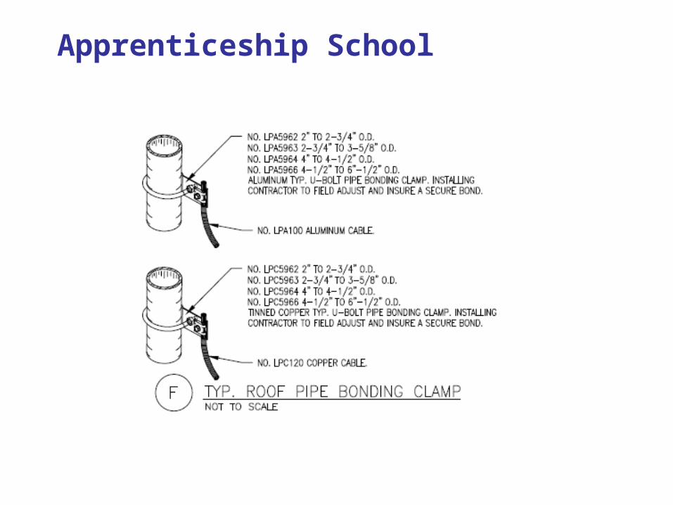
Apprenticeship School
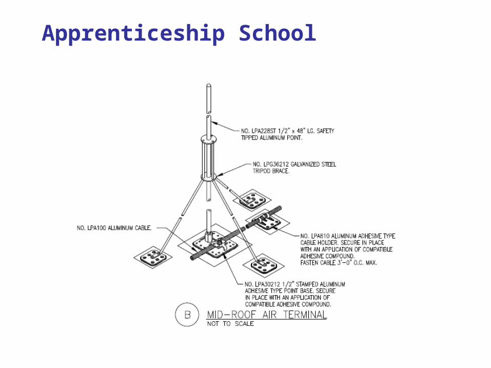
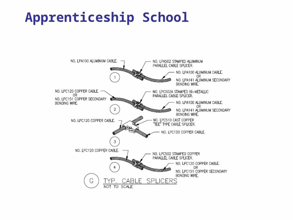
Apprenticeship School
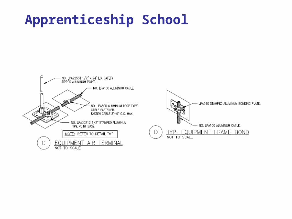
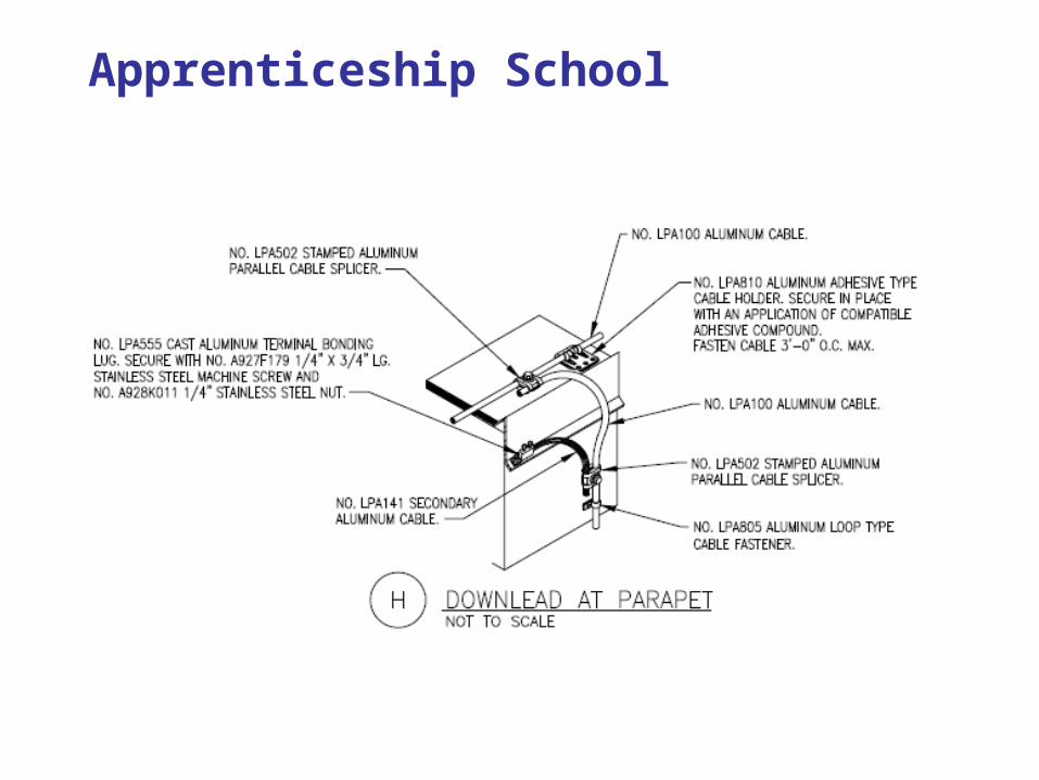
Apprenticeship School
Apprenticeship School
Apprenticeship School
Apprenticeship School
Apprenticeship School
Apprenticeship School
Apprenticeship School
Apprenticeship School

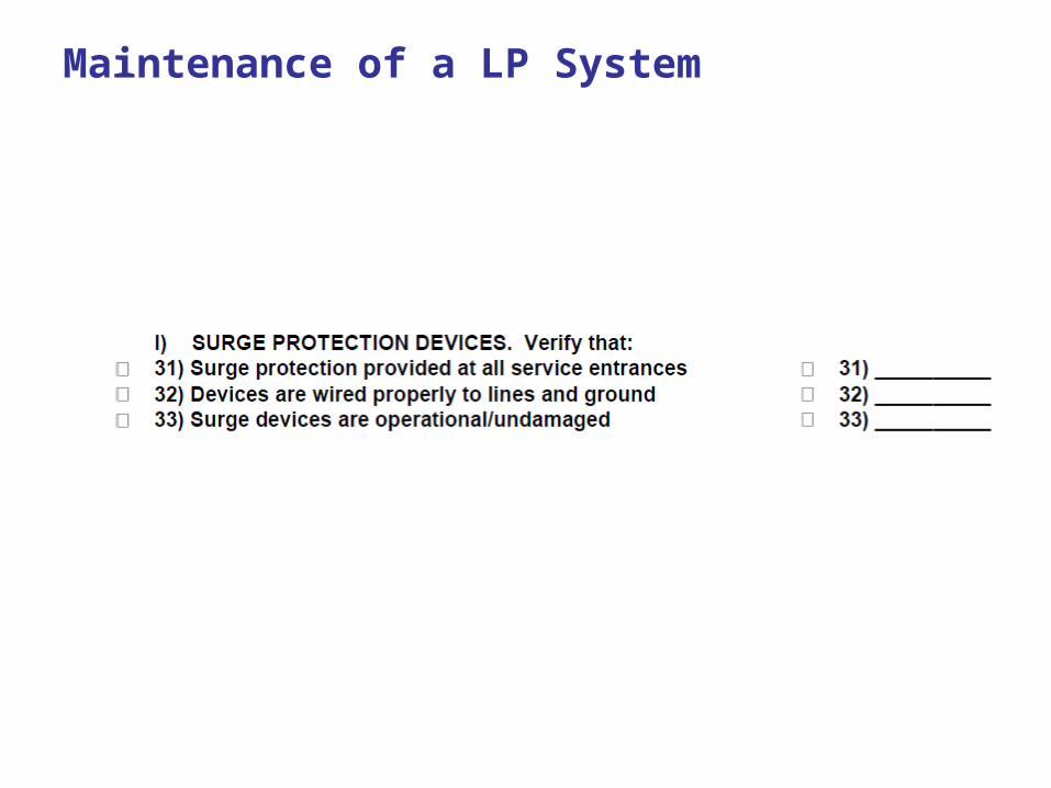
Surge Protection Devices
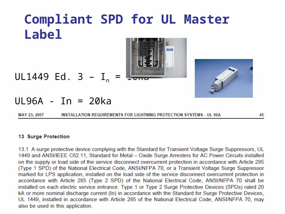
Compliant SPD for UL Master Label
UL1449 Ed. 3 – In = 10ka
UL96A - In = 20ka
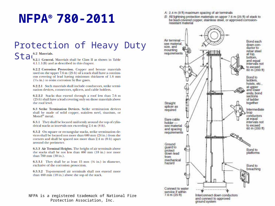
Protection of Heavy Duty Stacks:
NFPA® 780-2011
NFPA is a registered trademark of National Fire Protection Association, Inc.
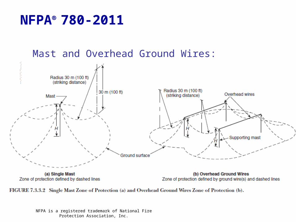
Mast and Overhead Ground Wires:
NFPA® 780-2011
NFPA is a registered trademark of National Fire Protection Association, Inc.
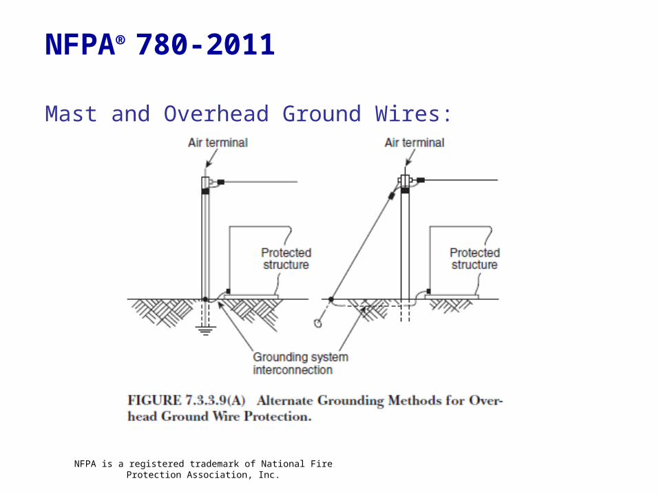
Mast and Overhead Ground Wires:
NFPA® 780-2011
NFPA is a registered trademark of National Fire Protection Association, Inc.
Inspection and Maintenance of a lightning protection system:
•Annual visual inspections
•Thoroughly inspected every 5 years
Inspection and Maintenance
National Fire Protection Assoc. # 780 Annex D
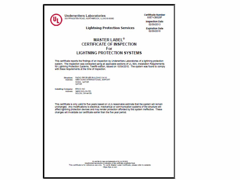
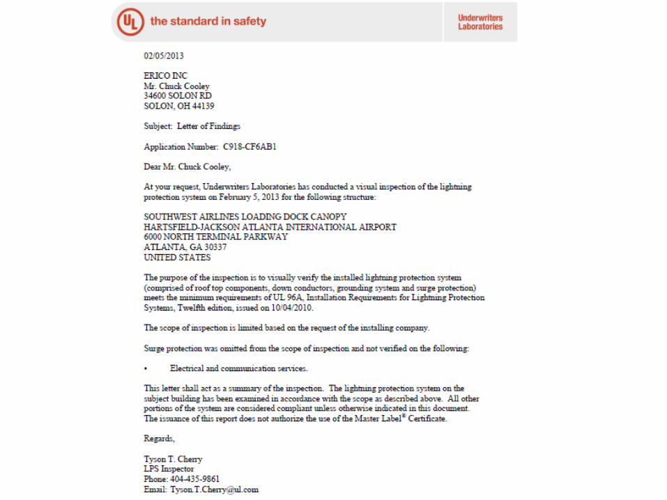
Underwriters’ Laboratories # 96A UL Master Label Letter of Findings
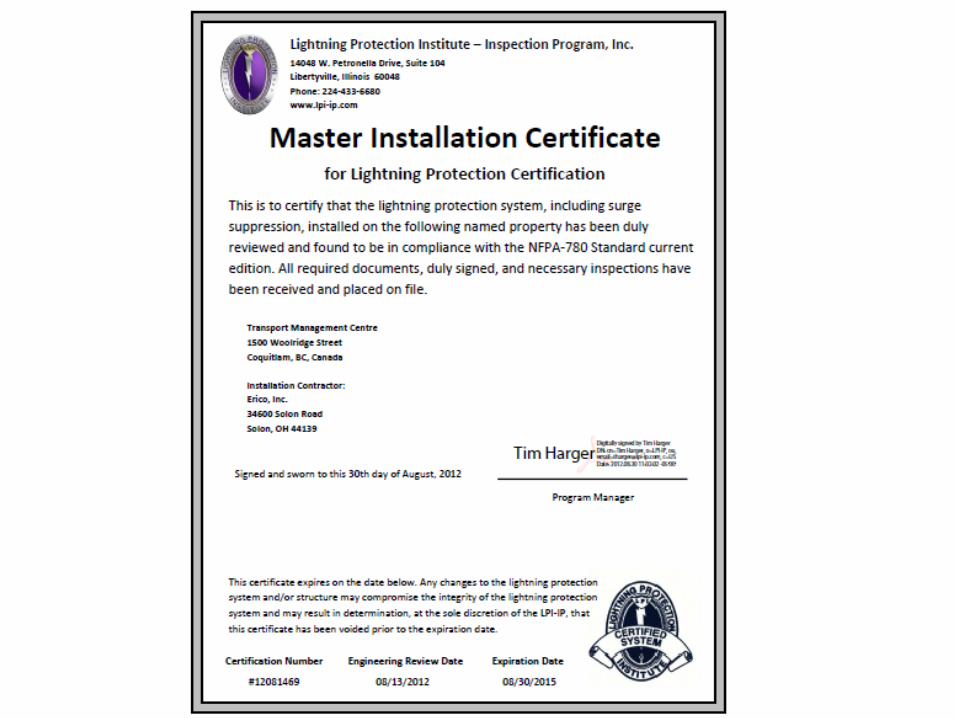
Lightning Protection Institute # 175 LPI Reconditioned Master Installation Certificate LPI Limited Scope Inspection
Maintenance of a LP System
Maintenance of a LP System
Maintenance of a LP System
Maintenance of a LP System
Maintenance of a LP System
Maintenance of a LP System
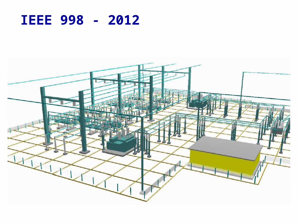
IEEE 998 - 2012
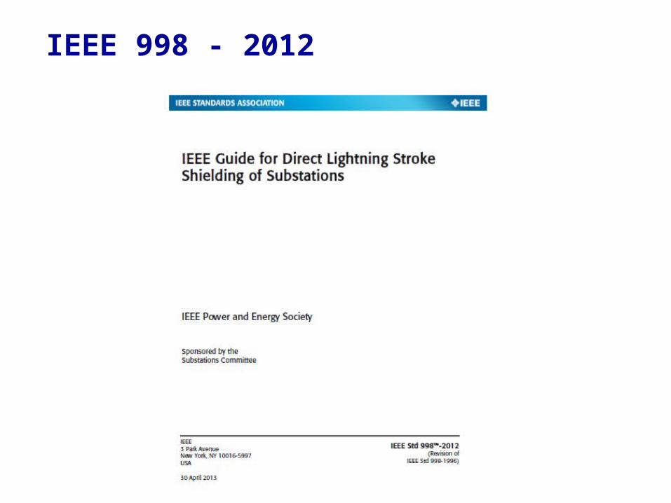
IEEE 998 - 2012
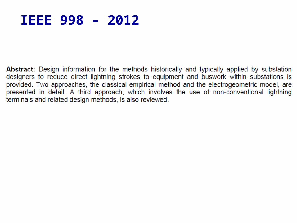
IEEE 998 – 2012
IEEE 998 – 2012
2 designs methods which have been used to protect substations from direct lightning strokes:
• Fixed Angles• Empirical curves
•CVM – Collection Volume Method
IEEE 998 - 2012
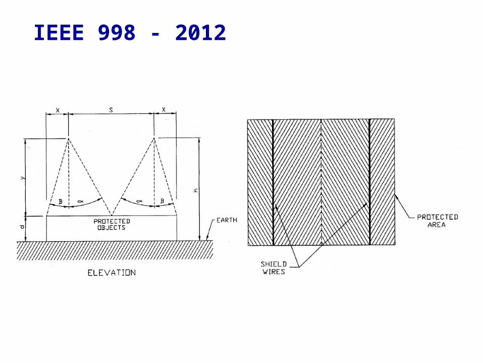
Fixed Angle:
It was recognized that the area protected by a lightning rod was bound by a curved surface rather than a fixed plane.
More than likely the fixed angle was used as a convenience to determine the approximation of the boundaries against lightning strikes.
The angles used: approximately 30/45 degrees.
IEEE 998 - 2012
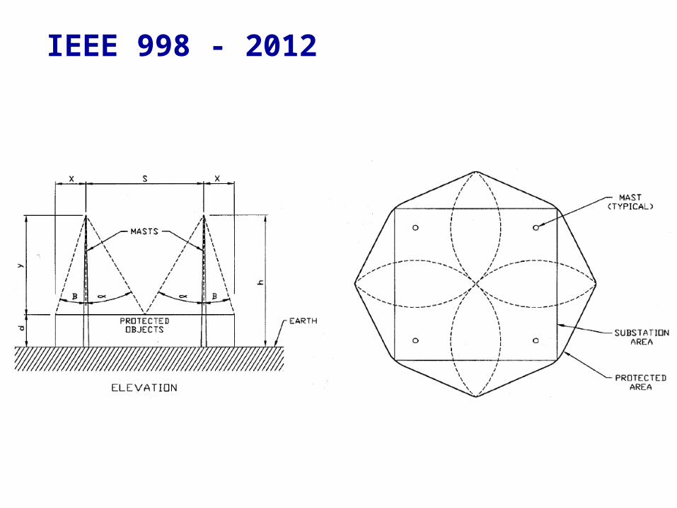
IEEE 998 - 2012
Installations can be expensive Coverage area of any one mast is small Limited coverage by static wires/masts Risk of static wire failure
Disadvantages of Fixed Angle/Mast Sys.
Collection Volume Method (CVM)
Collection Volume Method (CVM)
Applied to 3D structures from original work of Dr A.J. Eriksson (1979, 1987)
The CVM is simply a physically-based, improved Electrogeometric Model.
Improved striking distance relationship:
ds = function (Ki, Ip)
where Ki is the field intensification factor near the prospective strike point (structure, structural feature or air terminal).
Collection Volume Method (CVM)
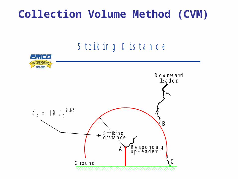
S t r i k i n g D i s t a n c e
D o w n w a r d le a d e r
S t r i k in gd is ta n c e
R e s p o n d in gu p - le a d e r
G r o u n d
A
C
B
d Is p 1 0 0 6 5.
Collection Volume Method (CVM)
Collection Volume Method
Downwardleader
Collectionvolume
Ground
AC
B
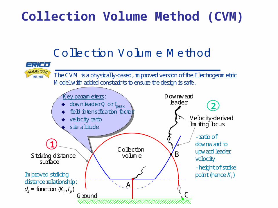
The CVM is a physically-based, improved version of the ElectrogeometricModel with added constraints to ensure the design is safe.
Key parameters: downleader Q or Ipeak
field intensification factor velocity ratio site altitude
1Striking distance
surface
Improved striking distance relationship: ds = function (Ki, Ip)
Velocity-derivedlimiting locus
2
- ratio of downward to upward leader velocity
- height of strike point (hence Ki)
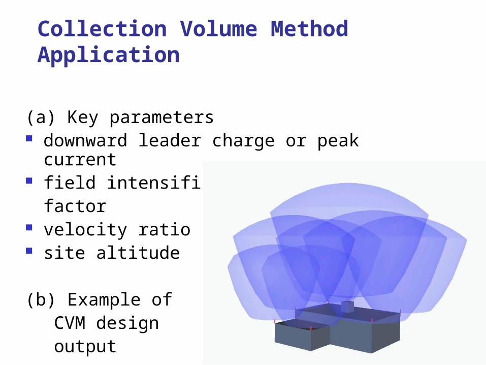
Collection Volume Method Application
(a) Key parameters downward leader charge or peak current field intensification
factor velocity ratio site altitude
(b) Example of CVM design output
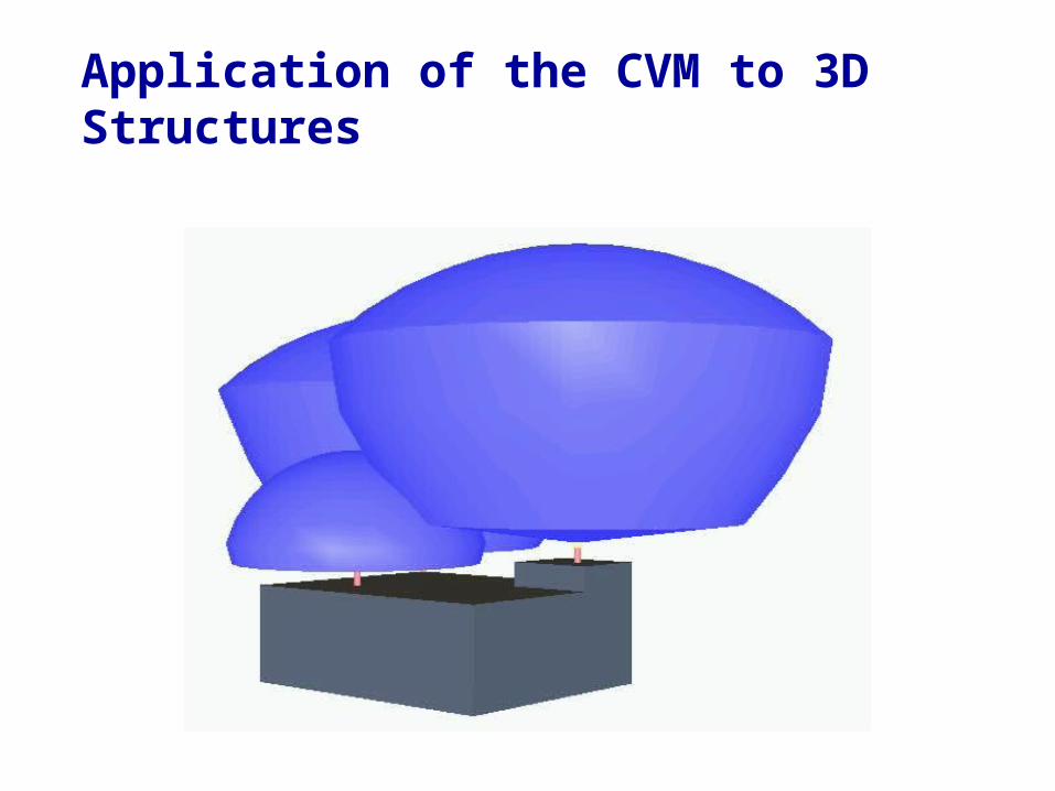
Application of the CVM to 3D Structures
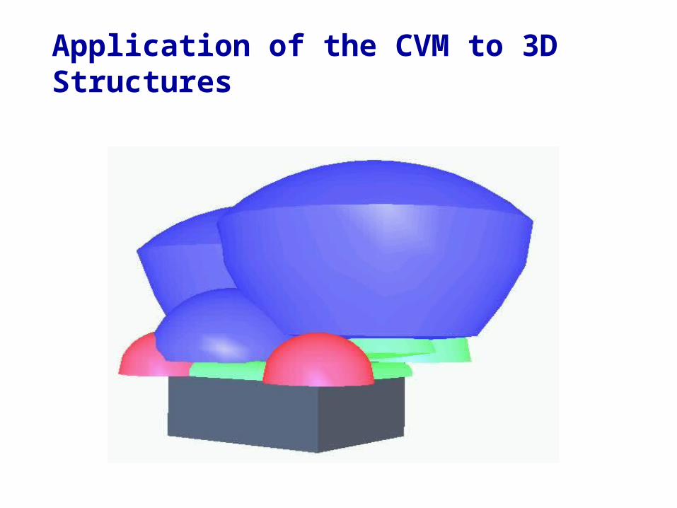
Application of the CVM to 3D Structures
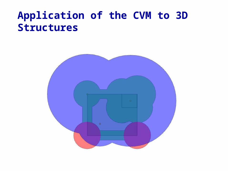
Application of the CVM to 3D Structures

Strike Current (X)
Level of Protection (Y) Exceedance Probability
2.9 kA Level I – Very High 99%
5.4 kA Level II – High 97%
10.1 kA Level III – Medium 91%
15.7 kA Level IV - Low 84%
The protection zone provided by the air termination shall be such that it becomes the preferred strike point for all discharges exceeding a peak amplitude return strike current of “X” kA according to the statistical level “Y”.
Application of the CVM to 3D Structures
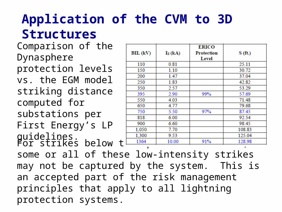
For strikes below the specified kA level, some or all of these low-intensity strikes may not be captured by the system. This is an accepted part of the risk management principles that apply to all lightning protection systems.
Comparison of the Dynasphere protection levels vs. the EGM model striking distance computed for substations per First Energy’s LP guidelines.
Application of the CVM to 3D Structures
Advantages
vs. static wire if strike bypasses from the side, CVM will intercept.
Larger protection area. Protect skater antenna and control house.
Dis-Advantages
Cannot get inspected by 3rd party (UL – LPI)
Application of the CVM to 3D Structures
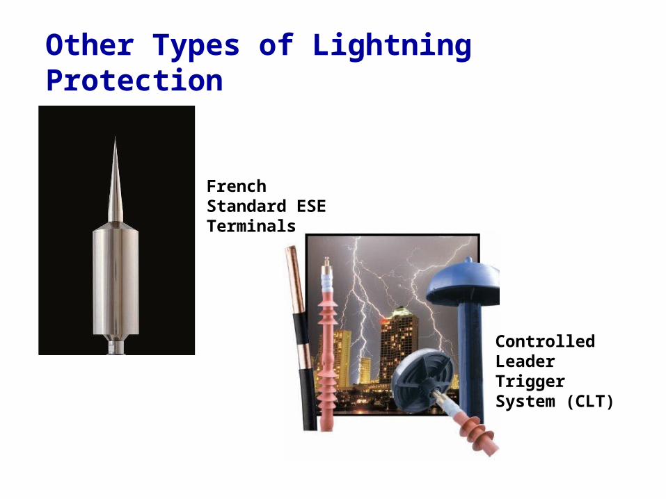
French Standard ESE Terminals
Controlled Leader Trigger System (CLT)
Other Types of Lightning Protection
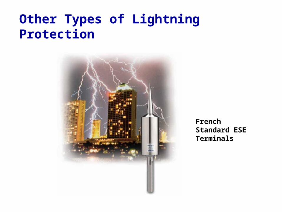
French Standard ESE Terminals
Other Types of Lightning Protection
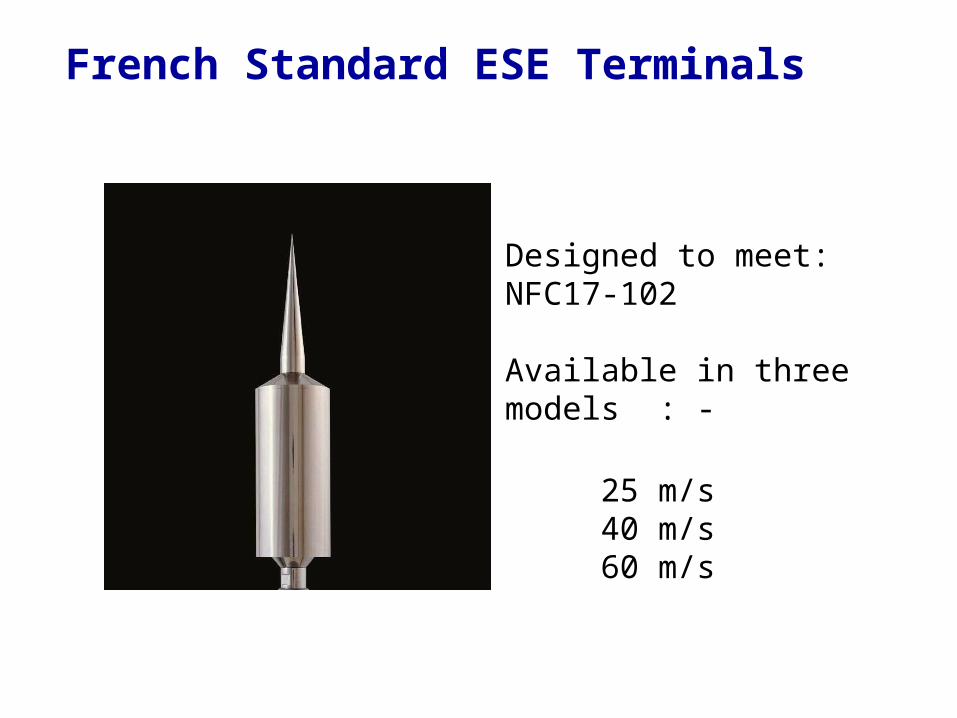
Designed to meet:NFC17-102
Available in three models : -
25 m/s40 m/s60 m/s
French Standard ESE Terminals
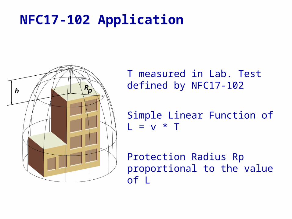
T measured in Lab. Test defined by NFC17-102
Simple Linear Function of L = v * T
Protection Radius Rp proportional to the value of L
NFC17-102 Application
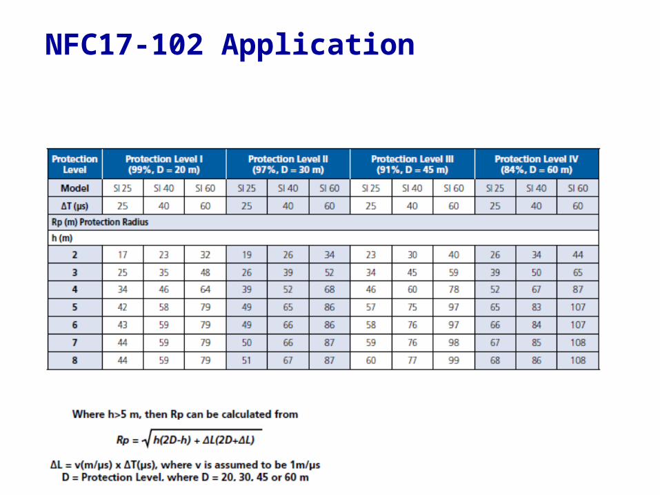
NFC17-102 Application

Thank you for your time!
This concludes the educational content of this activity
www.erico.com